Universiti Teknologi PETRONAS Civil Engineering Department Design of Steel Structures (VCB 3022) Connections with Bolts Lecture: Dr. Montasir O. Ahmed

Welcome message from author
This document is posted to help you gain knowledge. Please leave a comment to let me know what you think about it! Share it to your friends and learn new things together.
Transcript

Universiti Teknologi PETRONAS
Civil Engineering Department
Design of Steel Structures (VCB 3022)
Connections with Bolts
Lecture: Dr. Montasir O. Ahmed

Analyze and design STEEL connections
SUJECT TO COMPLEX LOADING (in-plane
and out-of-plane )
CLO3

Learning outcome
After the session the students will be able to:
Identify different classes of connections used in steel structure construction
Properties, advantage and drawbacks of commonly used connections.
Analysis and Design of Connections with bolts and pins using EC 3-1-8

Main classes of connection
1. Connection where a change of direction occurs.
e.g. beam-to-column connections, beam-to-beam connections and connections
between different members in trusses.
2. Connection which ensure manageable sizes of steel members for transportation and
erection
e.g. columns are normally spliced every two or three storeys.
3. Connections provided where there is a change of component
e.g. column bases, and connections beams or columns with walls, floors and roofs.


CONNECTIONS IN SIMPLE CONSTRUCTION
• The typical connections in braced multi-storey buildings of simple connection, single
storey buildings and portal frames are:
• Web cleat connections
• Flexible end plate connections (Header plate connection)
• Fin plate connections
• The connections using the above types are:
• Beam to column connection using web cleats
• Beam to beam connection using web cleats
• Beam to column using flexible end plates
• Beam to beam connection using flexible end plates
• Beam to column connection using fin plates
• Beam to beam connection using fin plates

Different configurations in simple joints
Joint about major axisJoint about the minor axis
Beam to column single sided joint configurations:
Beam to column double sided joint configurations:
Joint about major axis Joint about the minor axis

Uncoped beam supported
on beam web
Single Coped beam supported
on beam web
Double Coped beam
supported on beam web
Uncoped beam supported
on beam web
Single Coped beam
supported on beam web
Double Coped beam
supported on beam web
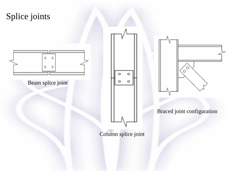
Splice joints
Beam splice joint
Column splice joint
Braced joint configuration
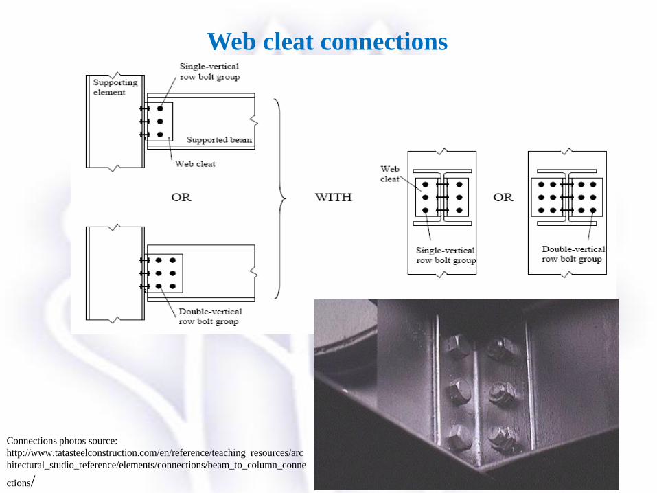
Web cleat connections
Connections photos source:
http://www.tatasteelconstruction.com/en/reference/teaching_resources/arc
hitectural_studio_reference/elements/connections/beam_to_column_conne
ctions/
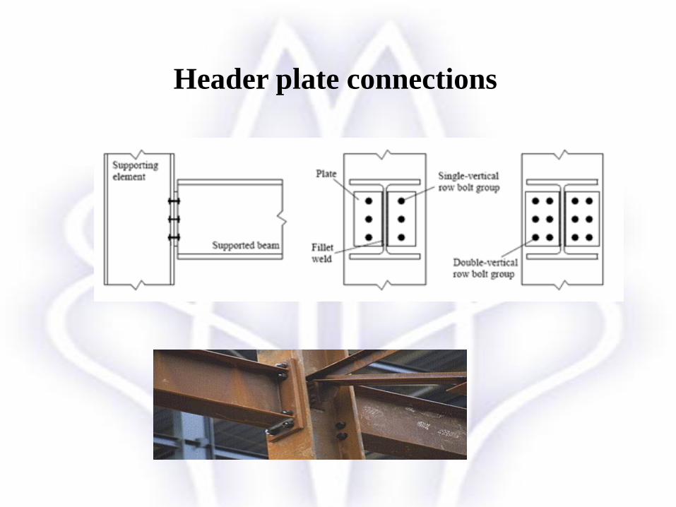
Header plate connections

Fin plate connections

• “Connection” and “Joints” are often regarded as the same.
• EC3-1-8 defines them slightly differently.
• A connection is the location at which two or more elements
meet. For design purposes it is the assembly of the basic components required to
represent the behaviour during the transfer of relevant internal forces and moments
at the connection.
• The joint is the zone where two or more members are
connected.
Example: A beam–to–column joint consists of a web panel and either
one connection (single sided joint configuration) or two connections
(double sided joint configuration).
Eurocode EC3-1-8: Joints and Connections
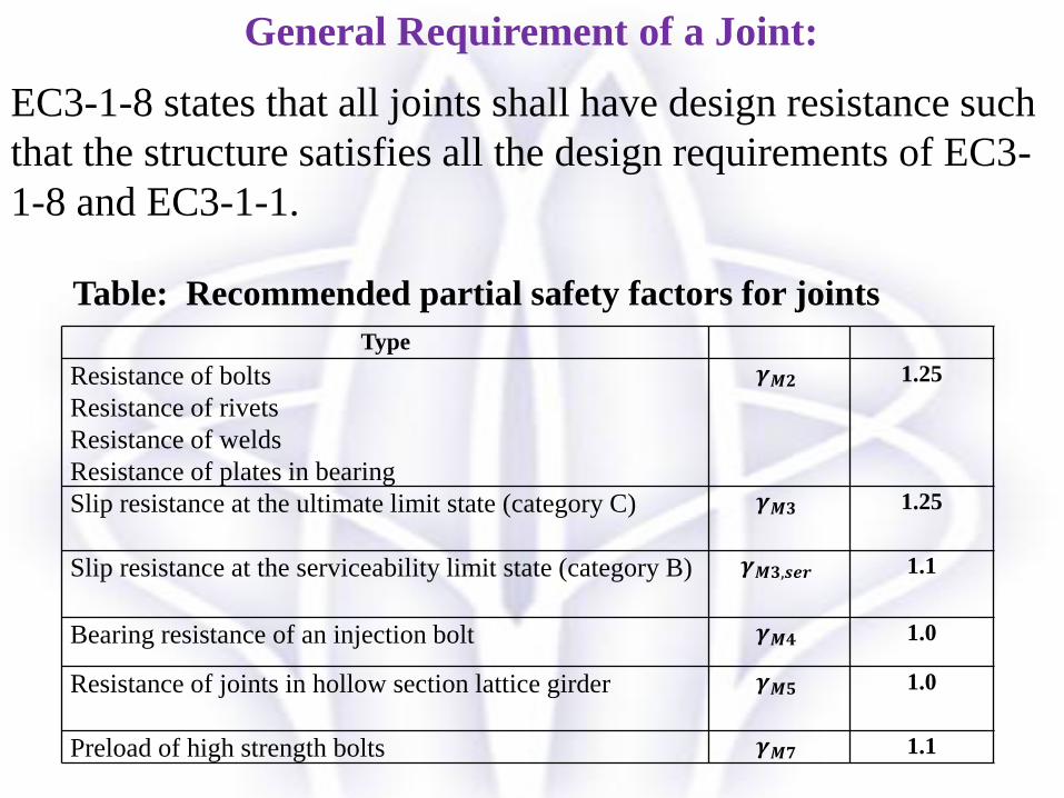
General Requirement of a Joint:
EC3-1-8 states that all joints shall have design resistance such
that the structure satisfies all the design requirements of EC3-
1-8 and EC3-1-1.
Type
Resistance of bolts
Resistance of rivets
Resistance of welds
Resistance of plates in bearing
𝜸𝑴𝟐 1.25
Slip resistance at the ultimate limit state (category C) 𝜸𝑴𝟑 1.25
Slip resistance at the serviceability limit state (category B) 𝜸𝑴𝟑,𝒔𝒆𝒓 1.1
Bearing resistance of an injection bolt 𝜸𝑴𝟒 1.0
Resistance of joints in hollow section lattice girder 𝜸𝑴𝟓 1.0
Preload of high strength bolts 𝜸𝑴𝟕 1.1
Table: Recommended partial safety factors for joints
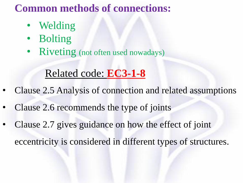
Common methods of connections:
• Welding
• Bolting
• Riveting (not often used nowadays)
• Clause 2.5 Analysis of connection and related assumptions
• Clause 2.6 recommends the type of joints
• Clause 2.7 gives guidance on how the effect of joint
eccentricity is considered in different types of structures.
Related code: EC3-1-8

“To be capable of safely transferring load from the supported
members to the supporting member”.
This implies that three properties of the connection need to be
considered: strength, stiffness, deformation capacity.
Requirements of a connection:
Beam-to-column connections:
• Very frequent connection
• Classified by their stiffness as nominally pinned, semi-rigid or rigid.
• Classified by their capability to transfer moments as nominally
pinned, partial-strength and full-strength connections.

Connections: Bolts, rivets and pins
Two types/classes of bolts are provided for use by EC3-1-8:
2005 (in Table 3.1) :
Ordinary bolts
High strength bolts.
• The rules in EC3-1-8 are valid for 7 bolt classes 4.6, 4.8, 5.6,
5.8, 6.8, 8.8 and 10.9.
• Ordinary bolts or ordinary grade bolts are put in bolt classes
4.6, 4.8, 5.6, 5.8 and 6.8
• High strength grip bolts or high strength bolts are put in
classes 8.8 and 10.9. They can be used for preloaded bolts which are
characterized by a slip-type resistance in shear.
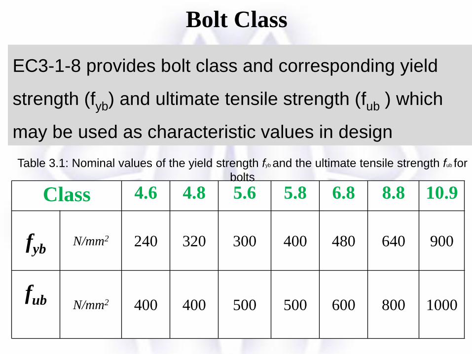
Class 4.6 4.8 5.6 5.8 6.8 8.8 10.9
fybN/mm2 240 320 300 400 480 640 900
fub N/mm2 400 400 500 500 600 800 1000
EC3-1-8 provides bolt class and corresponding yield
strength (fyb) and ultimate tensile strength (fub ) which
may be used as characteristic values in design
Bolt Class
Table 3.1: Nominal values of the yield strength fyb and the ultimate tensile strength fub for
bolts
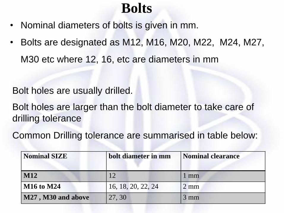
• Nominal diameters of bolts is given in mm.
• Bolts are designated as M12, M16, M20, M22, M24, M27,
M30 etc where 12, 16, etc are diameters in mm
Nominal SIZE bolt diameter in mm Nominal clearance
M12 12 1 mm
M16 to M24 16, 18, 20, 22, 24 2 mm
M27 , M30 and above 27, 30 3 mm
Bolt holes are usually drilled.
Bolt holes are larger than the bolt diameter to take care of
drilling tolerance
Common Drilling tolerance are summarised in table below:
Bolts

Symbols for spacing of fasteners (excerpted from EC 3-3-8)
d0 is the diameter of the hole
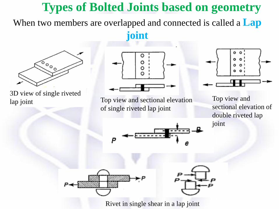
3D view of single riveted
lap joint Top view and sectional elevation
of single riveted lap joint
Top view and
sectional elevation of
double riveted lap
joint
Types of Bolted Joints based on geometry
When two members are overlapped and connected is called a Lap
joint
Rivet in single shear in a lap joint
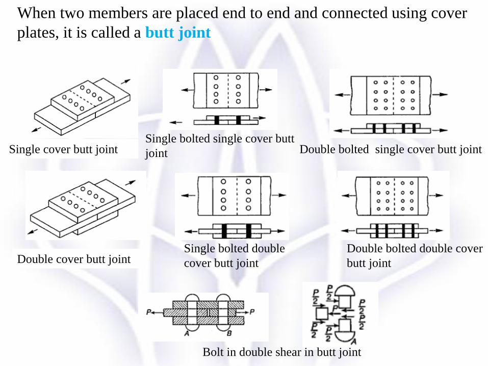
Single cover butt jointSingle bolted single cover butt
joint
Double bolted double cover
butt joint
Single bolted double
cover butt jointDouble cover butt joint
Bolt in double shear in butt joint
When two members are placed end to end and connected using cover
plates, it is called a butt joint
Double bolted single cover butt joint

Double cover butt joints are preferred due to two
reasons.
1. The shear force transmitted by the members’ acts on two
planes whereas in lap joint it acts on only one plane.
Therefore the shear carrying capacity in double cover
butt joint is twice that in a lap joint.
2. Also in double cover butt joint, there is no eccentricity
of force and thus bending is eliminated.
Lap Joint Vs Butt Joints
Simple joints can be classified based on the nature of force
transfer as follows
Direct shear joints
Direct tension joints
Eccentric connections: There are two principal types of
eccentric loaded connections namely:
Bolt group in direct shear and torsion
Bolt group in shear and tension
Types of joints based on force transfer

A shear joint can fail in 5 modes:
1. Mode 1: By shear on the bolt shank
2. Mode 2: By bearing on the member or bolt
3. Mode 3: By shear at the end of the member
4. Mode 4: By tension in the member
5. Mode 5: By block shear.
prevented by providing sufficient number of
bolts of suitable diameter.
prevented by providing sufficient
end distance.
prevented by design tension members
for its effective area
failure is observed in a shear joint involving a
group of bolts. To prevent such failure check
the effective shear area as per the code
provisions.

The bolts are arranged to act in single or double shear.
Figure: A joint in which the bolt is in single shear.
Shearing strength
If the loads are large enough, the bolt may fail by shearing as shown
below:
The area resisting this failure is the circular area of the bolt shank. The
shear resistance per plane is calculated using equation given in table 3.4 of
BS EN 1993 -1-8.
Direct shear joints
2
,
M
ubv
Rdv
AfF
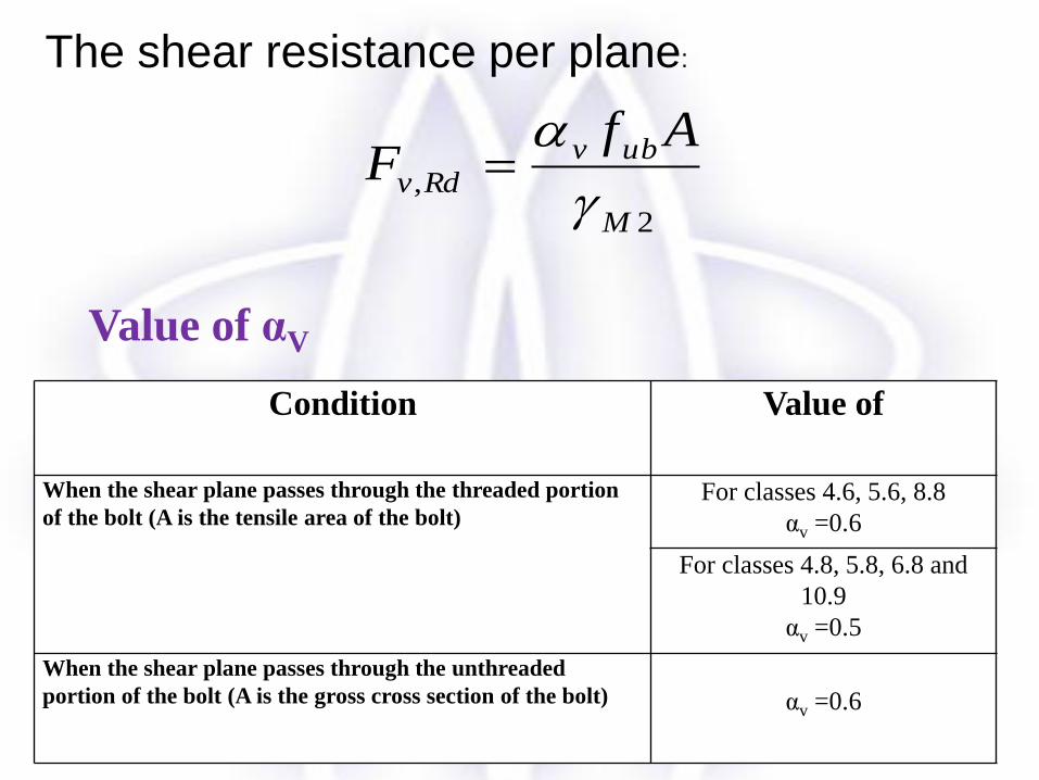
The shear resistance per plane:
Condition Value of
When the shear plane passes through the threaded portion
of the bolt (A is the tensile area of the bolt)For classes 4.6, 5.6, 8.8
αv =0.6
For classes 4.8, 5.8, 6.8 and
10.9
αv =0.5
When the shear plane passes through the unthreaded
portion of the bolt (A is the gross cross section of the bolt) αv =0.6
Value of αV
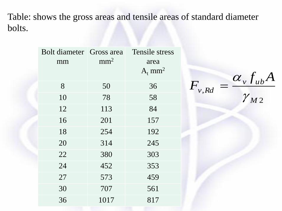
Bolt diameter
mm
Gross area
mm2
Tensile stress
area
At mm2
8 50 36
10 78 58
12 113 84
16 201 157
18 254 192
20 314 245
22 380 303
24 452 353
27 573 459
30 707 561
36 1017 817
Table: shows the gross areas and tensile areas of standard diameter
bolts.
2
,
M
ubv
Rdv
AfF

Bearing strength
• When relatively large diameter bolts are used to connect two thin steel
plates, then failure will take place by tearing of plates by bolt.
• This type of failure is known as bearing failure.
• The area of contact of bolt with the plates on one side is actually semi-cylindrical
(figure 7.8), but since the variation of stress around the perimeter of hole is
indeterminate, the strength of bolt in bearing is determined using equation in table
3.4 of EC3 -1-8
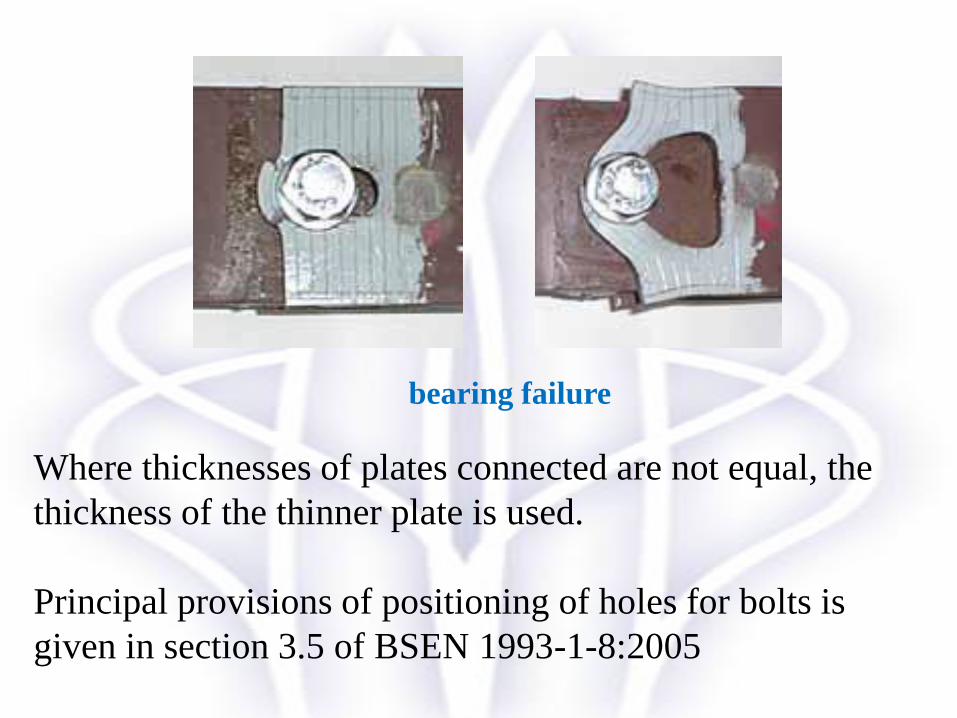
Where thicknesses of plates connected are not equal, the
thickness of the thinner plate is used.
Principal provisions of positioning of holes for bolts is
given in section 3.5 of BSEN 1993-1-8:2005
bearing failure

2
1
,
M
ub
Rdb
dtfakF
0
1
3d
ed
4
1
3 0
1 d
pd
For edge bolts:
For inner bolts:
Where ab is the smallest of αd ; 𝑓𝑢𝑏
𝑓𝑢or 1.0
αd is evaluated in the direction of load transfer separately for edge
bolts and inner bolts by following expressions:
k1 is evaluated perpendicular to the direction of load transfer
separately for edge bolts and inner bolts by following expressions:
For edge bolts: k1 is the smallest of or 2.5
For inner bolts: k1 is the smallest of or 2.5
Strength of bolt in bearing

• Block tearing or block shear is a potential failure mode in
bolted connections for tension members, coped beams and
gusset plates.
• Block tearing consists of failure in shear at the row of bolts
along the shear face of the hole group accompanied by tensile
rupture along the line of bolt holes on the tension face of the
bolt group.
• Typically this failure mode is characterised by tearing out of a
block of steel with a combination of tension and shear failures
through the bolt holes.
• Clause 3.10.2 provides the guidelines for design for block
tearing.
Design for block tearing/ block shear
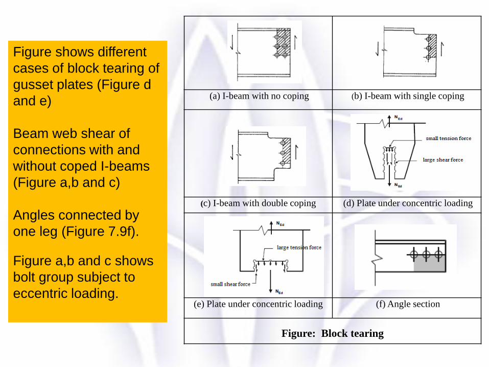
(a) I-beam with no coping (b) I-beam with single coping
(c) I-beam with double coping (d) Plate under concentric loading
(e) Plate under concentric loading (f) Angle section
Figure: Block tearing
Figure shows different
cases of block tearing of
gusset plates (Figure d
and e)
Beam web shear of
connections with and
without coped I-beams
(Figure a,b and c)
Angles connected by
one leg (Figure 7.9f).
Figure a,b and c shows
bolt group subject to
eccentric loading.

02
,2,3
15.0
M
nvy
M
ntuRdeff
AfAfV
02
,1,3
1
M
nvy
M
ntu
Rdeff
AfAfV
Figure d and e shows symmetric bolt group subject to concentric
loading. The design block shearing resistance 𝑉𝑒𝑓𝑓,1,𝑅𝑑 is given by
Note that in the above expressions, for tension rupture net area is taken
whereas for shear yielding the gross area is used.
Figure a,b and c shows bolt group subject to eccentric loading.
The design block shearing resistance 𝑉𝑒𝑓𝑓,2,𝑅𝑑 is given by
Ant is net area subjected to tension;
Anv is net area subjected to shear.

The code has two categories for connections loaded in tension as per clause
3.4.2 BS EN 1993-1-8:
Category D: Non – preloaded: (clause 3.4.2(1) a)
Bolt classes 4.6 to 10.9 should be used. Where connections are subject to
variations in tensile loading, this type of connection is not to be used.
However, they can be used in connections subject to normal wind loads.
Category E: Preloaded: (clause 3.4.2(1) b)
Bolt classes 8.8 and 10.9 are used with controlled tightening as per reference
Standards 1.2.7: Group & to be applied.
Direct Tension joints
2
2
,
M
sub
Rdt
AfkF
2
,
6.0
M
upm
Rdp
ftdB
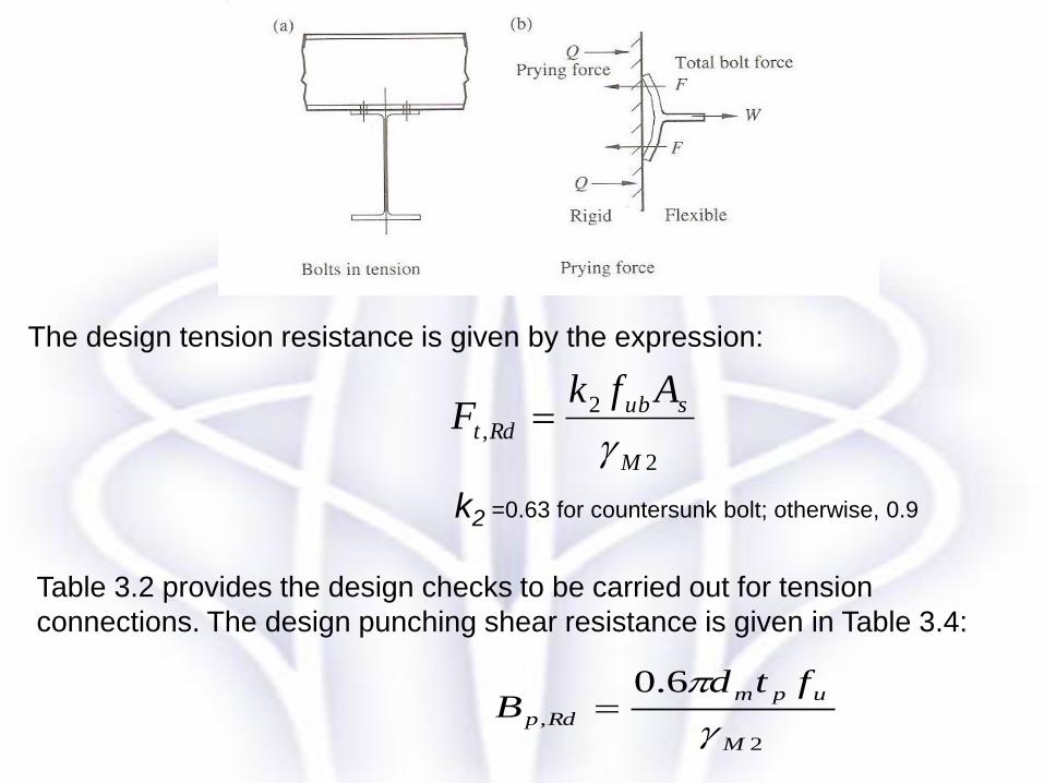
The design tension resistance is given by the expression:
k2 =0.63 for countersunk bolt; otherwise, 0.9
Table 3.2 provides the design checks to be carried out for tension
connections. The design punching shear resistance is given in Table 3.4:


Figure below shows a lap joint. Two 10 mm thick S275 plates
have been joined using a single bolt of 16 mm diameter and
grade 8.8. Determine the following:
Check on minimum and maximum edge and end distances.
Also the load capacity of the connection with respect to
• Bolt shear
• Bolt bearing
• Plate bearing
• Block shear
• Tension capacity of plates
Example 1

From EC3-1-1 Table 3.1, for grade S 275 steel, fy= 275 N/mm2
and fu = 430 N/mm2. From the figure it is seen that there is only
shear plane and the bolts are fully threaded.
The edge and end distances provided have to be compared with
minimum and maximum end and edge distances required as per
table 3.3 of EC 3-1-8
Solution
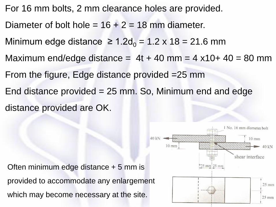
For 16 mm bolts, 2 mm clearance holes are provided.
Diameter of bolt hole = 16 + 2 = 18 mm diameter.
Minimum edge distance ≥ 1.2d0 = 1.2 x 18 = 21.6 mm
Maximum end/edge distance = 4t + 40 mm = 4 x10+ 40 = 80 mm
From the figure, Edge distance provided =25 mm
End distance provided = 25 mm. So, Minimum end and edge
distance provided are OK.
Often minimum edge distance + 5 mm is
provided to accommodate any enlargement
which may become necessary at the site.

2
,
M
ubv
Rdv
AfF
kNAf
FM
ubv
Rdv 288.6025.1
1578006.0
2
,
u
ub
f
f
86.1430
800
u
ub
f
f
46.0183
25
3 0
1
d
edd
(a) Bolt shearing:
Bolt shearing resistance,
For grade 8.8 bolts, fub = 800 N/mm2 and Area of bolt = At = 157 mm2
As per EC 3-1-8 clause 3.6.1 (10) single rivets should not be used in single lap joints.
However ignoring that;
or 1.0
> 40kN
in the direction of load transfer at end bolts:
Therefore, = 0.46
Bolts are adequate in shear
(b) Bolt bearing:
αb is the smallest of αd;
d
2
1,
M
ubRdb
dtfkF
Bolt bearing resistance

7.18.20
2 d
e
19.27.118
258.27.18.2
0
2 d
e
kNdtfk
FM
ub
Rdb 447.5525.1
101643046.019.2
2
1
,
For edge bolts k1 is the smallest of :or 2.5
Therefore bearing resistance is given by
>40kN
To determine k1:
Note that EC3 includes the bolt bearing and plate bearing in the same
equation.
(c) Plate bearing:
Discussed above
02
,2,3
5.0
M
nvy
M
ntu
Rdeff
AfAfV
1025ntA
1025nvA
430uf
275yf
kNV Rdeff 693.82693.394331
10)25(275
25.1
10)25(4305.0,2,
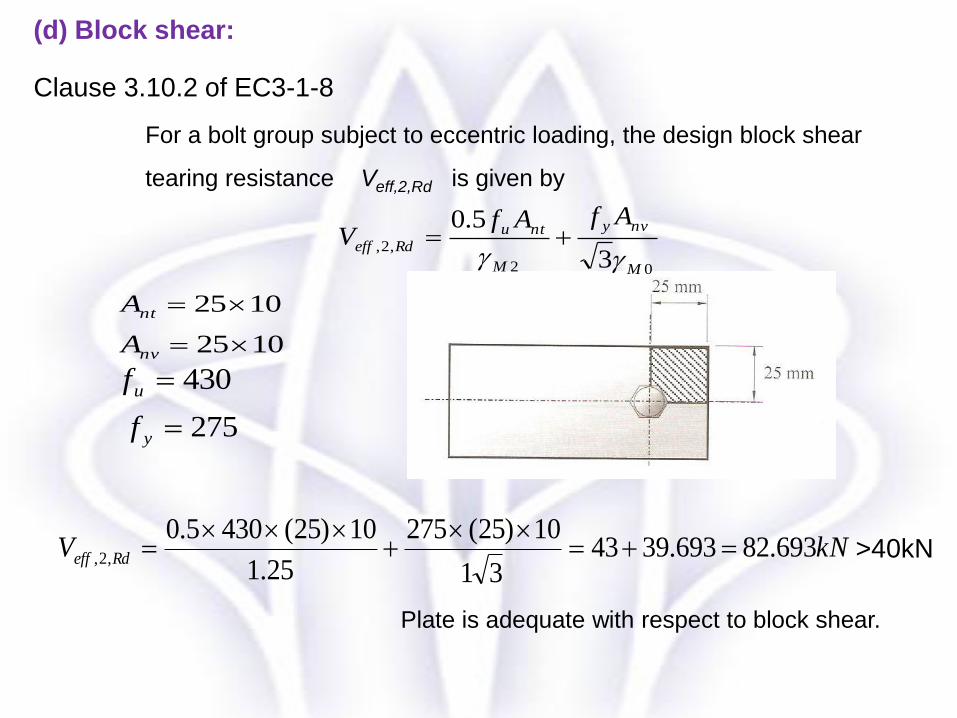
(d) Block shear:
Clause 3.10.2 of EC3-1-8
For a bolt group subject to eccentric loading, the design block shear
tearing resistance Veff,2,Rd is given by
>40kN
Plate is adequate with respect to block shear.
kNAf
NM
y
Rdpl 5.1370.1
2751050
0
,
kN
fAN
M
unet
Rdu 072.9925.1
4301018509.09.0
2
,
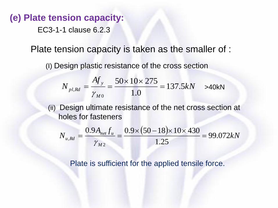
Plate tension capacity is taken as the smaller of :
(I) Design plastic resistance of the cross section
(ii) Design ultimate resistance of the net cross section at
holes for fasteners
(e) Plate tension capacity:
EC3-1-1 clause 6.2.3
>40kN
Plate is sufficient for the applied tensile force.

Considering (a), (b),(c),(d) and (e); the connection strength is
governed by the smallest value namely
(a) bolt shearing strength = 60.288kN
(b) & (c) bolt bearing strength = 55.447 kN
(d) block shearing = 82.69 kN
(e) Plate tension capacity = 99.072kN
Bolt bearing strength governs.
Maximum force that can be transmitted =55.447kN > 40 kN
OK.

Any questions?

Thank you
Related Documents