UNIVERSIDAD SAN FRANCISCO DE QUITO USFQ Colegio de Ciencias e Ingenierías Universal Automatic Mechanism for the Operation of CNC Lathe Chucks . Mauro Sebastián Rivadeneira Narea Carlos Nicolás Viñas Larrea Ingeniería Mecánica Trabajo de integración curricular presentado como requisito para la obtención del título de Ingeniero Mecánico Quito, 23 de diciembre de 2019

Welcome message from author
This document is posted to help you gain knowledge. Please leave a comment to let me know what you think about it! Share it to your friends and learn new things together.
Transcript

UNIVERSIDAD SAN FRANCISCO DE QUITO USFQ
Colegio de Ciencias e Ingenierías
Universal Automatic Mechanism for the Operation of
CNC Lathe Chucks .
Mauro Sebastián Rivadeneira Narea
Carlos Nicolás Viñas Larrea
Ingeniería Mecánica
Trabajo de integración curricular presentado como requisito
para la obtención del título de
Ingeniero Mecánico
Quito, 23 de diciembre de 2019

2
UNIVERSIDAD SAN FRANCISCO DE QUITO USFQ
COLEGIO DE CIENCIAS E INGENIERIAS
HOJA DE CALIFICACIÓN
DE TRABAJO DE INTEGRACIÓN CURRICULAR
Universal Automatic Mechanism for the Operation of CNC Lathe
Chucks
Mauro Sebastián Rivadeneira Narea
Carlos Nicolás Viñas Larrea
Calificación: /
Nombre del profesor, título académico Alfredo Valarezo, Ph.D.
Firma del profesor: _____________________________
Nombre del profesor, título académico David Escudero, Ph.D.
Firma del profesor: _____________________________
Quito, 23 de diciembre de 2019

3
Derechos de Autor
Por medio del presente documento certifico que he leído todas las Políticas y
Manuales de la Universidad San Francisco de Quito USFQ, incluyendo la Política de
Propiedad Intelectual USFQ, y estoy de acuerdo con su contenido, por lo que los derechos
de propiedad intelectual del presente trabajo quedan sujetos a lo dispuesto en esas
Políticas.
Asimismo, autorizo a la USFQ para que realice la digitalización y publicación de
este trabajo en el repositorio virtual, de conformidad a lo dispuesto en el Art. 144 de la
Ley Orgánica de Educación Superior.
Nombre y apellidos: Mauro Sebastián Rivadeneira Narea
Código: 00125281
Cédula de identidad: 1723203277
Firma del estudiante: _____________________________
Nombres y apellidos: Carlos Nicolás Viñas Larrea
Código: 00124785
Cédula de identidad: 1715740013
Firma del estudiante: _____________________________
Lugar y fecha: Quito, diciembre de 2019
4
RESUMEN
En el Ecuador actualmente no existe la manufactura de partes y piezas de acero
mediante forjado o moldeo. La industria acerera ecuatoriana está mayormente
concentrada en la creación de elementos estructurales y como tal solo se dedica a la
fabricación de varillas de acero a partir de acero reciclado o a la elaboración de perfiles
de acero mediante procesos de soldadura y doblado. Esto ha llevado a que la mayoría de
las piezas que se necesitan en el mercado local tengan que ser importadas o si se desean
hacer en el país estas deben ser maquinadas.
Al ser el maquinado el mayor proceso local de manufactura, muchas empresas y
talleres comenzaron con la compra de tornos y maquinaria CNC (Control Numérico
Computarizado). Gracias a la apertura y accesibilidad de estas máquinas dentro del
mercado en los últimos años. Sin embargo, muchos de estos talleres o fábricas no cuentan
con equipos CNC autosustentables, ya que estos dependen de un operador para su
alimentación y por ende no logran sacar el mayor provecho de la maquinaria CNC la cual
es manufacturar un gran número de piezas, acción que ayuda a igualar su costo frente a
tornos regulares más económicos. Este proyecto busca sentar el primero de los pasos
necesarios para el desarrollo de un sistema de alimentación de barras completamente
universal y autónomo. Siendo este paso el idear y diseñar un prototipo que opere
automáticamente el mandril de cualquier torno CNC.
El prototipo de concepto se realizó utilizando diferentes métodos de manufactura,
en su mayoría manufactura aditiva en forma de impresión 3D. Gracias a esta herramienta
se logró realizar diferentes iteraciones del diseño y mejorarlo a medida que se diseñaba.
También se utilizaron de piezas maquinadas a la medida debido a la falta de ciertos
componentes en el mercado local. Con el prototipo de concepto se puede visualizar la
apertura y clausura de un mandril de torno CNC. Se realizaron, además, cálculos y la
programación necesaria para la futura implementación de una máquina que utilice el
concepto aquí desarrollado para la implementación de un sistema de apertura de mandril
de tornos CNC que, al unirse con un alimentador de barras, se convertirá en un sistema
que completamente automatice los tornos CNC.
Palabras clave: CNC, maquinado, torno, mandril, automatización

5
ABSTRACT
In Ecuador there is currently no manufacturing of steel parts and pieces by forging or
molding. The Ecuadorian steel industry is focused on the creation of structural elements
and as such is only dedicated to the manufacturing of steel rods from recycled steel or on
the preparation of steel profiles using welding and bending processes. This has led to the
currents state where most of the parts that are needed in the local market must be imported
or machined if importing is not a possibility.
Since machining is by far the largest manufacturing process in the country, many
companies and workshops started purchasing CNC (Computer Numerical Control)
machinery such as lathes and mills. This shift is due to the opening and accessibility of
these machines within the market in recent years. However, many of these workshops or
factories do not have self-sustaining CNC equipment, since these depend on an operator
for their feeding and function and therefore fail to make the most of the true purpose of
CNC machinery, which is to manufacture a large number of parts, an action which helps
to equalize its cost against more economic NC (Numeric Control) or traditional, non-
computerized, lathes. This project seeks to establish the first of the necessary steps for the
development of a completely universal and autonomous bar feeding system. This step
being the design and design of a prototype that automatically operates the chuck of any
CNC lathe.
The concept prototype was made using different manufacturing methods, mostly additive
manufacturing in the form of 3D printing. Thanks to this tool, different iterations of the
design were made and improved as the design went along. Custom machined parts were
also used due to the lack of certain components in the local market. With the concept
prototype you can visualize the opening and closing of a CNC lathe chuck. Together with
the design of a concept prototype, design calculations were made, together with the
necessary programming for the future implementation of a machine that uses the concept
here developed. This future iteration of the chuck opening mechanism should be joined
with a bar feeder design that aims to finally create a completely autonomous CNC lathe
system.
Key words: CNC, lathe, chuck, machining, automatization

6
Table of Contents
Introduction ............................................................................................................................. 9
Problem Definition ................................................................................................................ 9
Need Identification ............................................................................................................. 13
Design Concept ..................................................................................................................... 13
Concept Evaluation and Selection ................................................................................. 15
Project Management .......................................................................................................... 19
Budget...................................................................................................................................... 20
Materials ................................................................................................................................. 20
Tool Material ......................................................................................................................... 20
Housing Material ................................................................................................................. 26
Component Selection ......................................................................................................... 31
Prototype Design ................................................................................................................. 32
Engineering Experiment ................................................................................................... 36
Design Report ....................................................................................................................... 37
Discussion .............................................................................................................................. 43
safety through design ......................................................................................................... 43
Executive summary ............................................................................................................ 44
Bibliography .......................................................................................................................... 46
Anexo A: Plano explosivo .................................................................................................. 47
Anexo B: Provisional Arduino Code .............................................................................. 48
Anexo C: Individual piece Drawings ............................................................................. 51

7
ÍNDICE DE TABLAS
Table 1: Weighted matrix for Chuck Operation (the lower the better) ......................... 16 Table 2: Weighted matrix for movement Mechanism ................................................... 17
Table 3: Weighted matrix for Tool Alignment (the lower the better) ........................... 18 Table 4: Gantt Diagram for the project ......................................................................... 19 Table 5: Budget ............................................................................................................. 20 Table 6: AISI 1018 CD Mechanical Properties ............................................................. 22 Table 7: Se Calculations: Tool with AISI 1018 ............................................................. 23
Table 8: AISI 4041 Steel Properties .............................................................................. 25 Table 9:Se Calculations: Tool with AISI 4340 ............................................................. 25 Table 10:AISI 1018 HR Steel Properties ...................................................................... 28 Table 11: Se Calculations: Housing with AISI 1018 HR .............................................. 28 Table 12:Fastening Torque Tries in (Nm) ..................................................................... 36
Table 13: Code Variable definitions .............................................................................. 41

8
ÍNDICE DE FIGURAS
Figure 1:Automatic Lathe (notice bar feeder) ................................................................ 11
Figure 2: Bar Feeding mechanism from the Polytechnic of Porto (Silva et al., 2018) ... 12 Figure 3: Chuck Diagram ............................................................................................... 13 Figure 4:Design Concepts Diagram ............................................................................... 14 Figure 5: Tool, Orthogonal View ................................................................................... 21 Figure 6: Tool, Dimensions for calculations .................................................................. 21
Figure 7: Housing: Motor Fastening .............................................................................. 26 Figure 8: Housing: Static Stress Analysis. Von Mises Criterion. .................................. 29 Figure 9: Housing: Static Stress Analysis Critical point. Von Mises Criterion. ............ 29
Figure 10: Housing: Static Stress Analysis Critical point. Von Mises Criterion). ......... 30 Figure 11: Housing: Fatigue Analysis Critical Point. Maximum Normal Stress. .......... 30 Figure 12: Chuck and Device, Side view ....................................................................... 32 Figure 13: Chuck and Device, Orthogonal-front view ................................................... 33
Figure 14:Main Rail ....................................................................................................... 34 Figure 15: Rail for Rack ................................................................................................. 34 Figure 16: Main housing, Orthogonal view ................................................................... 35 Figure 17: Housing top View ......................................................................................... 35
Figure 18: Left image, torque meter with attachment being placed on lathe wrench.
Right image, torque applied............................................................................................ 36
Figure 19: Torque meter wrench model specs................................................................ 37 Figure 20: The three iterations of the housing and rail rack design. On the left, the initial
design; on the right, the final design............................................................................... 39
Figure 21: Right, final iteration. Left, second iteration .................................................. 40 Figure 22: Final Iteration ................................................................................................ 40
Figure 23: Final Prototype, assembled ........................................................................... 41 Figure 24: PLC code ....................................................................................................... 42

9
INTRODUCTION
PROBLEM DEFINITION
Ecuador began the first decade of the 21st century with an important challenge: to
change the “production matrix” of the country. This change in production was proposed
in order to balance the imports and exports of the country. However, as time has passed
this has not happened. According to a report of the Latin American Association of Steel
(ALACERO) Ecuador only produces 30% of the steel it consumes (Redacción Líderes,
2016). It is widely known that the cause for this is that all steel production is focused on
the production of steel rods for concrete reinforcement, this is backed up by the World
Steel Association who published that the 576 tons of steel produced in Ecuador where in
continuously cast semis form, referring to billets and slabs, having no steel be produced
for casting or as ingots for material removal manufacturing (World Steel Association,
2018). On this same report we can find that 710 tons of hot rolled products are produced
in Ecuador referring to steel rods for concrete reinforcement.
Ecuador imports 1096 tons of steel, 850 tons of which is laminated steel (World
Steel Association, 2018). Local companies such as Kubiec or Sedemi use this steel to
make tubes, beams and other finished products via cold deformation and welding. This
means that a minor amount of steel is used in other applications. Since no casting is done
in country, this leaves chip removal processes as the only manufacturing option to
produce complex steel pieces. For this reason, changes introduced in the machining
industry could show the fastest results when aiming to improve Ecuadorian
manufacturing, as it is already stablished in the country.
Today workshops and factories of all sizes operate machining tools, many of them
have made the investment of purchasing CNC (Computer Numeric Control) machines. It

10
is widely known by all engineers that the precision of these machines is unparalleled and
that the finished products are much easier to be standardized and maintain uniformity,
since a computer program keeps the piece way above human tolerances.
A 1983 study done in Germany however, points out something obvious and that
has not changed throughout the years, the higher cost of CNC machines must be offset
with higher production numbers (Bussmann, Granow, & Hammer, 1983). Purchasing a
CNC lathe is a lifechanging purchase for a small shop, and a big investment for a factory.
Bussmann et al studied the benefits of a conventional hand lathe, a CNC non automatic
machine and an Automatic CNC lathe, and a very interesting point was drawn up. A non-
automatic CNC lathe has a major advantage in production time and precision over a
conventional lathe, however in both an operator must be present throughout operation, in
one case a machinist is operating the machine, in the other, an operator is loading and
unloading parts, running the program, and supervising the process. This means that both
lathes are tied to human work hours and shifts. In the case of a small workshop, who only
operates one shift, the CNC lathe will only be productive for a maximum of 8 hours a
day, although higher production will be achieved, return of investment time is not that
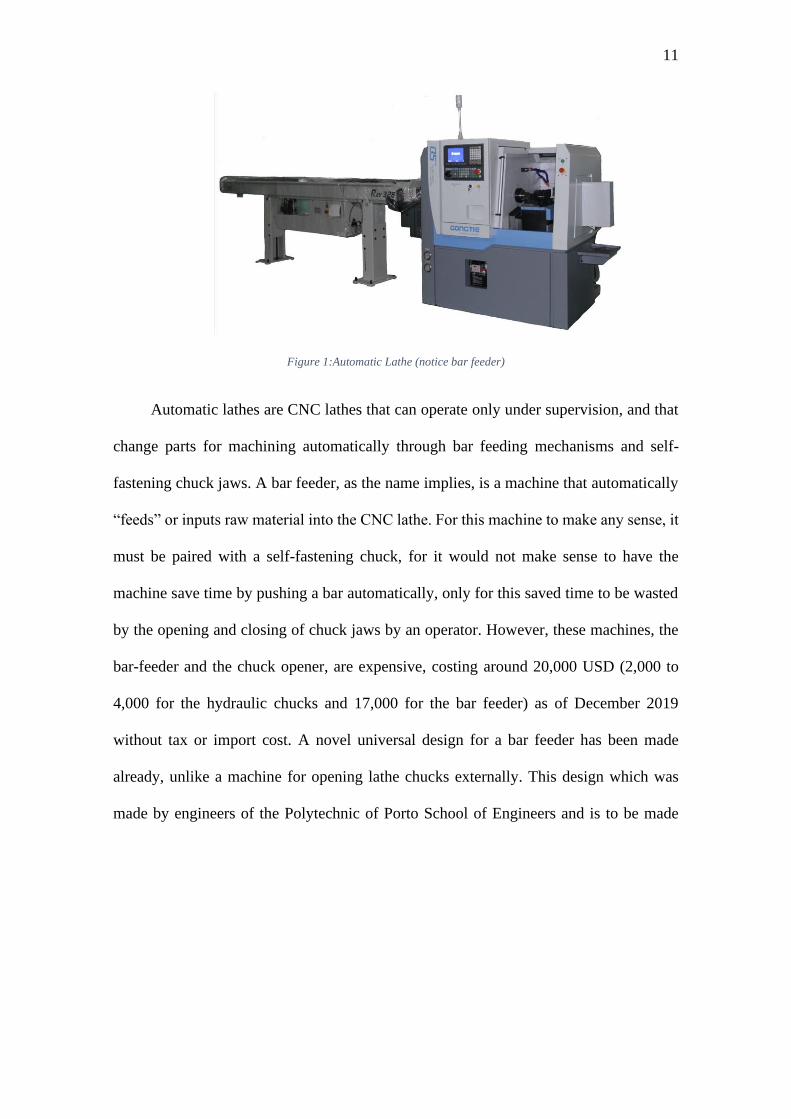
fast, taking into consideration the expensive cost of a CNC machine. Below, in Figure 1,
one can appreciate a CNC lathe that has been fitted with a Bar Feeder attachment. The
purpose and functions of such attachments is explained in the following paragraph.
11
Figure 1:Automatic Lathe (notice bar feeder)
Automatic lathes are CNC lathes that can operate only under supervision, and that
change parts for machining automatically through bar feeding mechanisms and self-
fastening chuck jaws. A bar feeder, as the name implies, is a machine that automatically
“feeds” or inputs raw material into the CNC lathe. For this machine to make any sense, it
must be paired with a self-fastening chuck, for it would not make sense to have the
machine save time by pushing a bar automatically, only for this saved time to be wasted
by the opening and closing of chuck jaws by an operator. However, these machines, the
bar-feeder and the chuck opener, are expensive, costing around 20,000 USD (2,000 to
4,000 for the hydraulic chucks and 17,000 for the bar feeder) as of December 2019
without tax or import cost. A novel universal design for a bar feeder has been made
already, unlike a machine for opening lathe chucks externally. This design which was
made by engineers of the Polytechnic of Porto School of Engineers and is to be made

12
adaptable with most kinds of CNC lathes. The design presented in this paper is shown
below.
Figure 2: Bar Feeding mechanism from the Polytechnic of Porto (Silva et al., 2018)
This design can be made to work with any kind of controller, so adapting it to a PLC
controller that manages both it and the chuck opening device seems plausible. Once the
design of a bar feeder has been taken into consideration. One must also take into
consideration taking into consideration that not all CNC lathes are compatible with all
chucks or CNC lathes, the prices above being for a HASS bar feeder, which is only
compatible with HASS machines, and a different assortment of chucks sold by catalogue.
Herein lies the problem to be solved by this project. How to open and close the chuck
jaws of any CNC lathe, even those that have no pneumatic attachment for their chuck
Operation.

13
NEED IDENTIFICATION
The client, BKB maquinaria industrial, has identified the need for a chuck opening and
closing mechanism that is universal, meaning it can be adapted to any CNC lathe and
automatic, needing no human interaction after setting parameters of work. Their needs
are listed as the following
• The machine must open and close a manual Chuck of either 8 or 10 inches with a
mechanism of its own
• It can use pneumatic or electric actuators (120 o 220 AC)
• It must have a controller that receives signals from the CNC itself.
Going further than the requested specs, the machine needs to be rugged and to withstand
the rigors of industrial life.
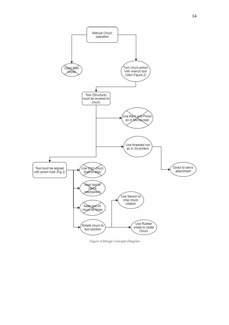
DESIGN CONCEPT
Taking into consideration the needs of
the machine, the following concept has
been formed as is shown in Figure 3. In
order to understand the Design
Concept Outline, figure 2: Chuck
Diagram, (to the right) must be viewed.
The crossed-out concepts where not
utilized. This is explained by the
weighted decision matrixes that follow the diagram.
Figure 3: Chuck Diagram
14
Figure 4:Design Concepts Diagram

15
CONCEPT EVALUATION AND SELECTION
The need to operate the manual chuck with a universal equipment that can withstand the
rigors of continuous manufacturing, and for a low cost gives the following criteria for
the selection of concept ideas: Complexity, Universality, Ruggedness, and Cost.
These are explained in further detail below
• Complexity takes into consideration:
o Number of parts
o Alterations made on the existing CNC lathe
o Difficulty of applying the concept
• Universality considers:
o Applicability to all models of CNC lathes
▪ Size considerations
▪ Differences in complexity of lathes
▪ Age of the lathes
• Ruggedness considers:
o Ability to bear a load
o Propensity of system to fail (Related to number of parts as well)
o Dependence on electric systems
• Cost considers:
o Price of parts existing in market
o Amount of custom parts to be machined

16
With these considerations in mind the following weighted matrices where constructed
based on the concepts previously shown in Figure 3.
The machine must operate a manual chuck that is installed on a CNC lathe. In order to do
so, two concepts or ideas where developed to accomplish this action. Concept 1 consist
of somehow getting inside the chuck and opening the jaws. This although the best option
for an individual solution, is not possible as intervening with the chuck itself could prove
very complex, plus the process derived from this would prove to only work on one model
of chuck making void the universality criteria of the evaluation. The risk of damaging the
chuck that is being intervened is also very real and therefore the only real option is to use
a wrench tool to turn the chuck pinion, which is Concept 2. This is universal and does not
require tampering with the chuck mechanism itself, making it a lot less complex in
comparison, but also maintaining some complexity as a mechanism to recreate this action
must now be created. Therefore Concept 2 is chosen with a lower valuation of 2, as can
be seen in Table 1.
Need Concept 1 Concept 2
Operate Manual
Chuck
Open from Inside Turn chuck pinions
with a wrench tool Criteria
5 3 Complexity
5 1 Universality
Total 10 2 Table 1: Weighted matrix for Chuck Operation (the lower the better)
The tool that is to operate the chuck must be lowered or moved toward the pinion hole.
Two concept ideas where evaluated in order to do so. The first concept consist of a rack
and pinion, similar to the way a microscope is moved, This concept is much more rugged
when compared to a threaded rod mechanism, concept 2, as used in a 3D printer, this is
due to the relative simplicity of a rack and pinion system, not only when manufacturing
but also universally. This universality is seen as the rack and pinion system can be easily
adapted to different motors and can also serve as a way to increase the torque output of
17
the motor, whereas the threaded rod design utilizes the raw torque of the actuator that is
attached to it. Finally, cost was analyzed, and a rack and pinion outshine to threaded rod
as it is easy to be manufactured in country, whereas most quality threaded rods must be
imported. These choices are weighted in Table 2 below, where a rack and pinion system
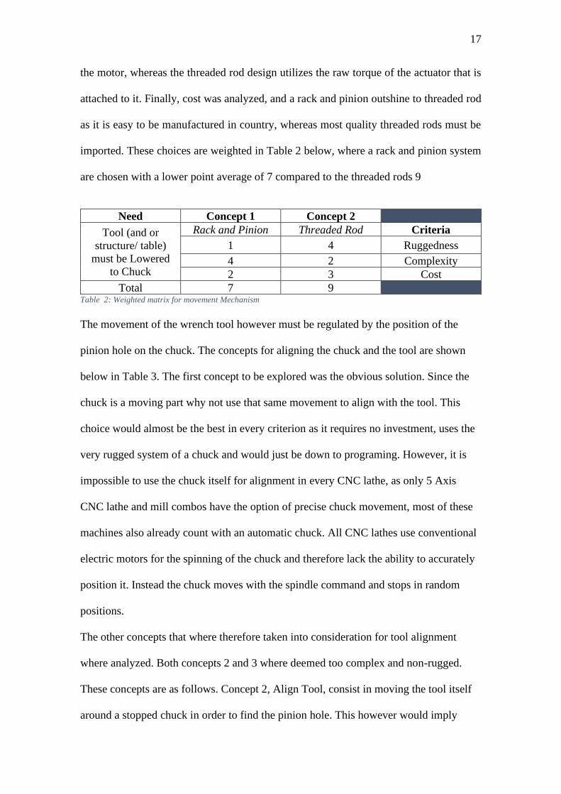
are chosen with a lower point average of 7 compared to the threaded rods 9
Need Concept 1 Concept 2
Tool (and or
structure/ table)
must be Lowered
to Chuck
Rack and Pinion Threaded Rod Criteria
1 4 Ruggedness
4 2 Complexity
2 3 Cost
Total 7 9 Table 2: Weighted matrix for movement Mechanism
The movement of the wrench tool however must be regulated by the position of the
pinion hole on the chuck. The concepts for aligning the chuck and the tool are shown
below in Table 3. The first concept to be explored was the obvious solution. Since the
chuck is a moving part why not use that same movement to align with the tool. This
choice would almost be the best in every criterion as it requires no investment, uses the
very rugged system of a chuck and would just be down to programing. However, it is
impossible to use the chuck itself for alignment in every CNC lathe, as only 5 Axis
CNC lathe and mill combos have the option of precise chuck movement, most of these
machines also already count with an automatic chuck. All CNC lathes use conventional
electric motors for the spinning of the chuck and therefore lack the ability to accurately
position it. Instead the chuck moves with the spindle command and stops in random
positions.
The other concepts that where therefore taken into consideration for tool alignment
where analyzed. Both concepts 2 and 3 where deemed too complex and non-rugged.
These concepts are as follows. Concept 2, Align Tool, consist in moving the tool itself
around a stopped chuck in order to find the pinion hole. This however would imply

18
either a form of a robotic arm or 360o tracks around the chuck. These are both complex
and expensive in their execution, apart from having a large amount of parts which as is
obvious would give many places where the design could fail. Concept 3, Keep on
Chuck, relies on a way to keep an actuator on the chuck while it rotates. This however
was deemed way too complex as it requires a way to stay attached to the spindle, which
rotates at many rpm, while keeping its feeding, be it electric or pneumatic, from
tangling up and breaking. This concept would also not be rugged or safe in the least as
tools from the CNC lathes tool holder would collide with it if they are long, which is
something that the client has warned about.
For these reasons it was determined that Concept 4, Rotate Chuck, which requires the
chuck to be rotated externally to an alignment point with a rubber wheel, was the best
choice of them all. A rubber wheel that can be moved and held in place on the chuck is
relatively inexpensive, makes use of the least amount of parts and can be moved out of
the way in an emergency, or when the tools exceed the length of the chuck.
Need Concept 1 Concept 2 Concept 3 Concept 4
Tool must
be aligned
with pinion
hole
Chuck code Align tool Keep on
chuck
Rotate
chuck Criteria
1 4 4 2 Ruggedness
1 4 5 2 Complexity
5 1 1 1 Universality
1 3 4 2 Cost
Total 8 12 14 7 Table 3: Weighted matrix for Tool Alignment (the lower the better)

19
PROJECT MANAGEMENT
The Project was managed by Mauro Rivadeneira, and Nicolas Viñas and was supervised and financed by Martin Gandara of BKB Maquinaria
Industrial. The following Timetable was agreed upon
Table 4: Gantt Diagram for the project
Activities 13/09 13/09 – 04/10 04/10/2019 04/10-22/10 22/10/2019 22/10-12/11 12/11/20197
Project Proposal
CAD Design
Material and Controller Selection
Prototype of Machine
Check and testing
User Manual Created and Final Report

20
BUDGET
The costs stated in Table 5 relate to the concept prototype designed. However, an initial
budget of more than 2000 USD was proposed for a further functional design. This
included an industrial grade control system such as a PLC rather than an arduino.
Arduino Mega 20.00
Electric
• 3 TB6600
Drivers
• 3 Nema 17
Stepper motors
• 12V 30 A Power
Source
• Hall Sensor for
PLC
187.30
Physical Parts and Pieces
• PETg 3D
Printing Filament
• 2 Nylon 6 sheets
• 1 steel axis
• 1 Nylon 6 Axis
• 1 Rubber wheel
52.50
Machining Cost 110.00
Total 369.80 USD Table 5: Budget
MATERIALS
TOOL MATERIAL
Experimentation showed that the machine for future development must be manufactured
in such a way as to resist an input torque of around 85 N-m. in order to properly secure
pieces to be machined. These experiments are detailed below in the experimentation
section of the report. With these 85 N-m. of input the following calculations were made
in order to correctly select a material. The calculations follow use formulas and the criteria
from the book: “Shigley’s Mechanical Engineering Design”.

21
The tool to be used in the future machine is to be analyzed as it is considered to be a
critical part for it is the only way that the input torque enters the machine. The tool and
the dimensions that pertain to the calculation are shown in Figures 4 and 5 below.
Figure 5: Tool, Orthogonal View
Figure 6: Tool, Dimensions for calculations
The critical area in the tool is at the end of the 12.70 mm squared cross-section shown in
the figures. First, this is the thinnest part in the piece and secondly the critical area should
be midpoint of this square shape. This is known from “Shigley’s Mechanical Engineering
Design” which states in page 99 of the 9ed that: “The maximum shear stress in a
rectangular profile, 𝑏 × 𝑐, is produced in the midpoint of the longer side b” ,in the tools
case b and c are equal, as it is a square. From this same page the following equation (3-
20) is used to calculate the maximum shear stress in a rectangular profile:
𝜏𝑚𝑎𝑥 =𝑇
𝑏𝑐2 (3 +
1.8
𝑏/𝑐)
This equation however simplifies to:
𝜏𝑚𝑎𝑥 =𝑇
𝑏3 (4.8)
Because the tool is a squared cross-section.

22
Taking our experimental Torque of 85 N-m., and a length b of 12.7 mm, the maximum
torque, 𝜏𝑚𝑎𝑥, at the tool is found to be 199.18 MPa.
The material chosen for the tool must resist this torque in the tool statically and at fatigue.
In order to figure this out the factor of safety must be analyzed in both cases. These where
calculated first using AISI 1018 CD steel as a design material as it is a common carbon
steel alloy that is both inexpensive, readily available and easy to machine. The material
properties for this steel where taken from “Shigley’s Mechanical Engineering Design”
book and are shown in the table below.
AISI 1018 CD Steel Properties (MPa)
Ultimate Tensile Stress (Sut) 440
Yield Strength (Sy) 370
Shear Ultimate Strength (Ssu) 𝑆𝑠𝑢 = 0.67𝑆𝑢𝑡 = 𝟐𝟗𝟒
Shear Yield Strength (Ssy) 𝑆𝑠𝑦 = 0.577𝑆𝑢𝑡 = 𝟐𝟏𝟑. 𝟏𝟓
Table 6: AISI 1018 CD Mechanical Properties
With the properties from table 6 and the maximum shear stress calculated above the
following calculations were made to figure out the static safety factor using the energy-
distortion method.
First the von misses stress was calculated with the following equation:
𝜎′ = (𝜎𝑥𝑦2 + 3𝜏𝑧𝑥
2)
In the present case 𝜎𝑥𝑦2 = 0, as the only force entering is torsion, and therefore only shear
stress must be accounted for. Plugging in 199.18 MPa for 𝝉𝒛𝒙 the von misses stress is
found to be 𝝈′ = 𝟑𝟒𝟒. 𝟒𝟗 MPa. Using this value and the yield strenght (Sy) from Table
6 to calculate the safety factor n with the following formula:
𝑛 =𝑆𝑦
𝜎′
23
one finds the safety factor to be 𝒏 = 𝟏. 𝟎𝟕, a value that barely passes safely when loaded
statically.
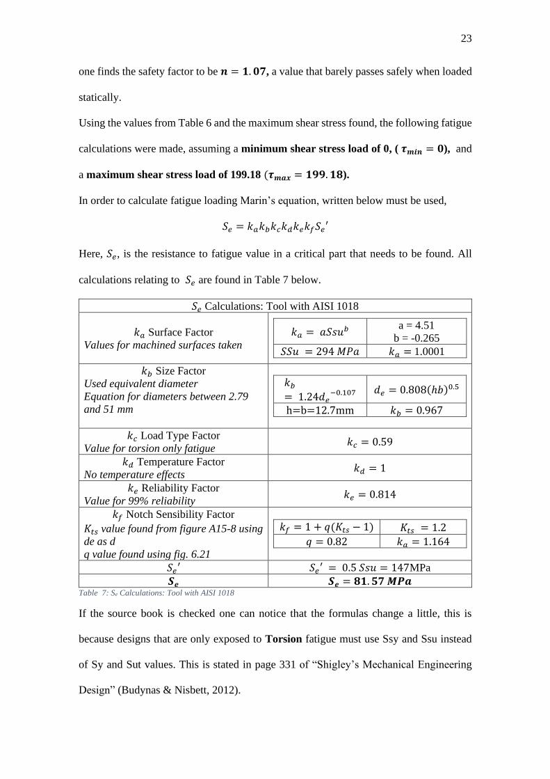
Using the values from Table 6 and the maximum shear stress found, the following fatigue
calculations were made, assuming a minimum shear stress load of 0, ( 𝝉𝒎𝒊𝒏 = 𝟎), and
a maximum shear stress load of 199.18 (𝝉𝒎𝒂𝒙 = 𝟏𝟗𝟗. 𝟏𝟖).
In order to calculate fatigue loading Marin’s equation, written below must be used,
𝑆𝑒 = 𝑘𝑎𝑘𝑏𝑘𝑐𝑘𝑑𝑘𝑒𝑘𝑓𝑆𝑒′
Here, 𝑆𝑒, is the resistance to fatigue value in a critical part that needs to be found. All
calculations relating to 𝑆𝑒 are found in Table 7 below.
𝑆𝑒 Calculations: Tool with AISI 1018
𝑘𝑎 Surface Factor
Values for machined surfaces taken
𝑘𝑎 = 𝑎𝑆𝑠𝑢𝑏 a = 4.51
b = -0.265
𝑆𝑆𝑢 = 294 𝑀𝑃𝑎 𝑘𝑎 = 1.0001
𝑘𝑏 Size Factor
Used equivalent diameter
Equation for diameters between 2.79
and 51 mm
𝑘𝑏
= 1.24𝑑𝑒−0.107
𝑑𝑒 = 0.808(ℎ𝑏)0.5
h=b=12.7mm 𝑘𝑏 = 0.967
𝑘𝑐 Load Type Factor
Value for torsion only fatigue 𝑘𝑐 = 0.59
𝑘𝑑 Temperature Factor
No temperature effects 𝑘𝑑 = 1
𝑘𝑒 Reliability Factor
Value for 99% reliability 𝑘𝑒 = 0.814
𝑘𝑓 Notch Sensibility Factor
𝐾𝑡𝑠 value found from figure A15-8 using
de as d
q value found using fig. 6.21
𝑘𝑓 = 1 + 𝑞(𝐾𝑡𝑠 − 1) 𝐾𝑡𝑠 = 1.2
𝑞 = 0.82 𝑘𝑎 = 1.164
𝑆𝑒′ 𝑆𝑒′ = 0.5 𝑆𝑠𝑢 = 147MPa
𝑺𝒆 𝑺𝒆 = 𝟖𝟏. 𝟓𝟕 𝑴𝑷𝒂 Table 7: Se Calculations: Tool with AISI 1018
If the source book is checked one can notice that the formulas change a little, this is
because designs that are only exposed to Torsion fatigue must use Ssy and Ssu instead
of Sy and Sut values. This is stated in page 331 of “Shigley’s Mechanical Engineering
Design” (Budynas & Nisbett, 2012).

24
Once the 𝑆𝑒 has been found to be 81.57 MPa the Fatigue Safety Factor can be found. In
this case the ASME criterion will be used as it is one of the most used when referring to
failure criteria. The ASME criteria fatigue safety factor is found using the following
equation:
𝑛𝑓 = √1
(𝜎𝑎 𝑆𝑒⁄ )2 + (𝜎𝑚 𝑆𝑠𝑦⁄ )2
Where 𝜎𝑎 = 𝜎𝑚 = 𝟗𝟗. 𝟓𝟗 𝑴𝐏𝒂 or 𝝉𝒎𝒂𝒙
𝟐⁄ . Plugging in the values above, one can find
that 𝒏𝒇 = 𝟎. 𝟕𝟏𝟓. Which means the tool using AISI 1018 steel will fail in fatigue. Since
the tool fails in fatigue it is possible to calculate the number of cycles until failure. These
are around 52,000 cycles. This might seems like a lot but one must take into consideration
the fact that the machine is designed to make machine shops operate in a 24 hr. cycle,
which taking into consideration an average of 30 minutes per machined item, means that
the machine will cycle 48 times a day, or 17,520 times a day. Meaning the tool must be
changed in less than 3 years of use. Even less if one considers the friction that will affect
the tool when entering and exiting the pinion hole.
If one wants to make a design robust design a different material must be considered. One
with higher mechanical property values. And one that is resistant to the wear and tear of
24 hr. use. For this reason, AISI 4340 steel will be used in the following calculations for
the tool. This steel is commonly used in applications which require resistance to torsion.
AISI 4340 Steel Properties (MPa) (Callister & Rethwisch, 2014)
Ultimate Tensile Stress (Sut) 745
Yield Strength (Sy) 472
Shear Ultimate Strength (Ssu) 𝑆𝑠𝑢 = 0.67𝑆𝑢𝑡 = 𝟒𝟗𝟗. 𝟏𝟓

25
Shear Yield Strength (Ssy) 𝑆𝑠𝑦 = 0.577𝑆𝑦 = 𝟐𝟕𝟐. 𝟑𝟒𝟒
Table 8: AISI 4041 Steel Properties
Since the only thing that changes are the material properties, the equations and figures
used to obtain values remain unchanged from the previous calculation with AISI 1018
Steel, as does the maximum shear strength, 𝜏𝑚𝑎𝑥, found from the initial 85 Nm. Torque.
With this in mind the static safety facture n is n = 1.37 using the energy-distortion
equation from the previous calculation. This value is gives an outstanding 37% of safety
from a higher torsion and is an industry standard. This will be reflected in the following
fatigue calculations.
As stated previously the equations used to calculate the safety factors won’t change, so
using Marin’s formula just like in the calculations before one can define the following
table and value for 𝑺𝒆 in order to later apply the ASME criterion for the safety factor.
Table 9 below shows this calculation in detail.
𝑆𝑒 Calculations: Tool with AISI 4340
𝑘𝑎 Surface Factor
Values for machined surfaces taken
𝑘𝑎 = 𝑎𝑆𝑠𝑢𝑏 a = 4.51
b = -0.265
𝑆𝑆𝑢 = 438.85 𝑀𝑃𝑎 𝑘𝑎 = 0.899
𝑘𝑏 Size Factor
Used equivalent diameter
Equation for diameters between 2.79
and 51 mm
𝑘𝑏
= 1.24𝑑𝑒−0.107
𝑑𝑒 = 0.808(ℎ𝑏)0.5
h=b=12.7mm 𝑘𝑏 = 0.967
𝑘𝑐 Load Type Factor
Value for torsion only fatigue 𝑘𝑐 = 0.59
𝑘𝑑 Temperature Factor
No temperature effects 𝑘𝑑 = 1
𝑘𝑒 Reliability Factor
Value for 99% reliability 𝑘𝑒 = 0.814
𝑘𝑓 Notch Sensibility Factor
𝐾𝑡𝑠 value found from figure A15-8 using
de as d
q value found using fig. 6.21
𝑘𝑓 = 1 + 𝑞(𝐾𝑡𝑠 − 1) 𝐾𝑡𝑠 = 1.2
𝑞 = 0.88 𝑘𝑎 = 1.176
𝑆𝑒′ 𝑆𝑒′ = 0.5 𝑆𝑠𝑢 = 249.575 𝑀𝑃𝑎
𝑺𝒆 𝑺𝒆 = 𝟏𝟐𝟐. 𝟓𝟑𝟖 𝑴𝑷𝒂 Table 9:Se Calculations: Tool with AISI 4340

26
Using the above values, the ASME fatigue safety factor 𝑛𝑓 is found to be 𝒏𝒇 = 𝟏. 𝟏𝟐𝟐.
This guarantees that the tool will not fail under fatigue. And therefore, no cycle
calculations must be made. It is for this reason that AISI 4340 is chosen as the material
for manufacturing the tool.
HOUSING MATERIAL
With the tool material selection now finished the attention is turned to the housing. This
piece which is detailed in the design section and has its own drawing in the annexes holds
the actuators that will create the 85 N-m. torque. The housing made for the prototype
holds the actuator with 4, 3mm fasteners. There is reason to believe therefore that the
plate to which the actuator is fastened to must resist the shear stress produced by the
actuator on these fasteners. The figure below pictures a simplified version of this part of
the housing. With the geometry from this diagram the fatigue safety factor will be
calculated using AISI 1018 HR steel.
Figure 7: Housing: Motor Fastening
With the above diagram it is possible to figure out the force that is applied on each of the
3mm fasteners. It is already known that T = 85 N-m, with this in mind, one can use
geometry to find that each of the fasteners is at a radial distance r of 21.92 mm from the

27
center of the plate, as they are laid out in a square formation. This is seen in the equation
below, where √2 is used because of the relations in a 45° right triangle.
𝑟 = √2 ∙ 31𝑚𝑚
2= 21.92 𝑚𝑚
After r has been found it is a question of applying equation (8-57) from Shigley’s
Mechanical Engineering Design to find the force loads due to moment F’’ with the
equation below.
𝐹′′ =𝑇
4𝑟2
In the present case there are four fasteners equidistant from where the moment is applied.
From this the force value is found to be 𝐹′′ = 969.4 𝑁. With this force value the stress
made by the fastener on the plate can be found using the 2 mm thickness of the plate and
the 3 mm diameter of the fastener. These two are multiplied to give an area of pressure
of A = 6mm2. Therefore, the axial stress on the plate is found simply by diving the force
by this value. This can be seen in the equation below
𝜎 =𝐹′′
𝐴
Where 𝝈 = 𝟏𝟔𝟏𝑴𝑷𝒂, with this value the calculations for the fatigue stress are found
using the following properties of AISI 1018 HR steel. This steel is chosen as it is one of
the most common plate steels used. It must be noted that the HR, or Hot Rolled values of
this steel are chosen as they represent the lowest values for AISI 1018 steel and give the
option of manufacturing the piece via the welding of steel plates to the housing. If the Hot
Rolled variety of AISI hold up, a machined CD, or Cold Drawn piece will have no
problem.

28
AISI 1018 HR Steel Properties (MPa)
Ultimate Tensile Stress (Sut) 400
Yield Strength (Sy) 220
Table 10:AISI 1018 HR Steel Properties
With these properties the Marin’s equation method previously applied to the tool is used.
The following values shown in Table 11 are used in the Se calculation.
𝑆𝑒 Calculations: Housing with AISI 1018 HR
𝑘𝑎 Surface Factor
Values for machined taken, as the
fastening holes are drilled
𝑘𝑎 = 𝑎𝑆𝑢𝑡𝑏 a = 4.51
b = -0.265
𝑆𝑢𝑡 = 400 𝑀𝑃𝑎 𝑘𝑎 = 0.92
𝑘𝑏 Size Factor
Value for axial only loads 𝑘𝑏 = 1
𝑘𝑐 Load Type Factor
Value for axial only fatigue 𝑘𝑐 = 0.85
𝑘𝑑 Temperature Factor
No temperature effects 𝑘𝑑 = 1
𝑘𝑒 Reliability Factor
Value for 99% reliability 𝑘𝑒 = 0.814
𝑘𝑓 Various Effect Factor
No notches or various effects are taken
into consideration for this fatigue load
𝑘𝑓 = 1
𝑆𝑒′ 𝑆𝑒′ = 0.5 𝑆𝑢𝑡 = 200 𝑀𝑃𝑎
𝑺𝒆 𝑺𝒆 = 𝟏𝟐𝟕. 𝟑𝟏 𝑴𝑷𝒂 Table 11: Se Calculations: Housing with AISI 1018 HR
With this value of Se ASME’s failure criteria from the previous calculations is used with
𝜎𝑎 = 𝜎𝑚 =161𝑀𝑃𝑎
2= 80.5 𝑀𝑃𝑎 to find that the fatigue safety factor is 𝒏𝒇 = 𝟏. 𝟑𝟔
allowing for this kind of fatigue load to be carried by the housing if constructed with any
variation of AISI 1018 steel. Making this material a completely viable choice.
Finally, a static study was performed using inventor stress analysis environment in order
to assess the most critical point of the housing. As are two pictures of the simulation
results being performed, shown in Figure 7 and 8.

29
Figure 8: Housing: Static Stress Analysis. Von Mises Criterion.
Figure 9: Housing: Static Stress Analysis Critical point. Von Mises Criterion.
30
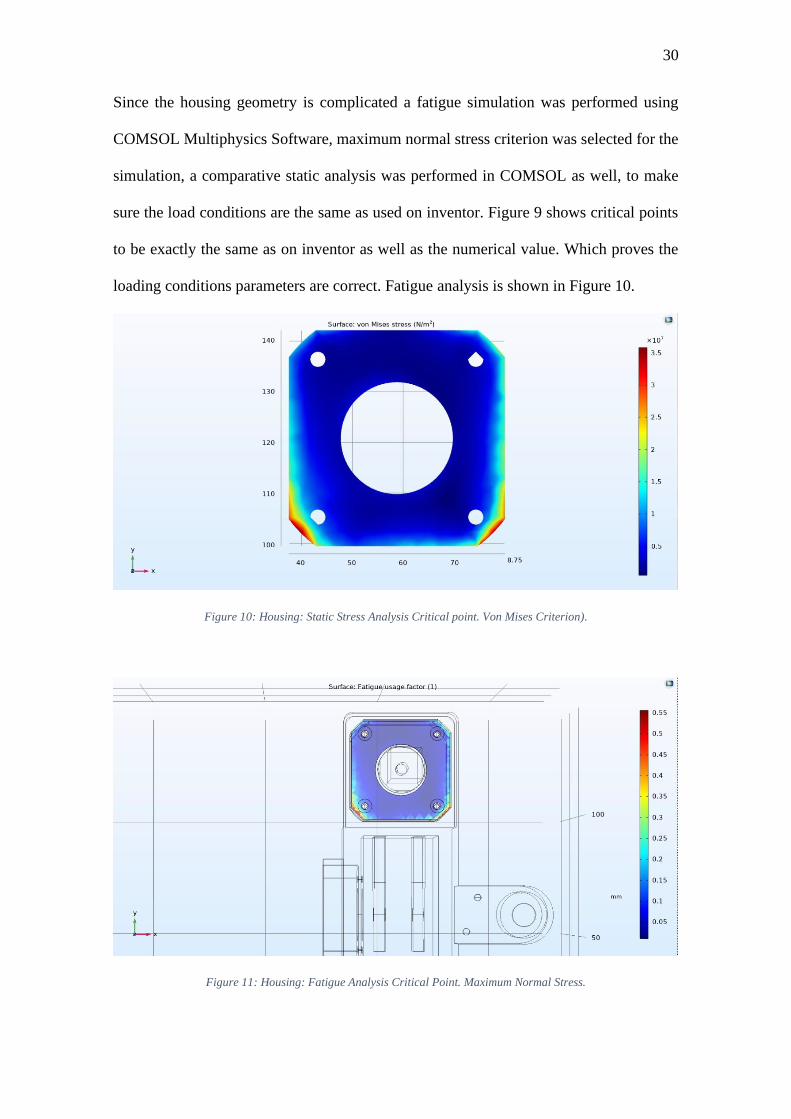
Since the housing geometry is complicated a fatigue simulation was performed using
COMSOL Multiphysics Software, maximum normal stress criterion was selected for the
simulation, a comparative static analysis was performed in COMSOL as well, to make
sure the load conditions are the same as used on inventor. Figure 9 shows critical points
to be exactly the same as on inventor as well as the numerical value. Which proves the
loading conditions parameters are correct. Fatigue analysis is shown in Figure 10.
Figure 10: Housing: Static Stress Analysis Critical point. Von Mises Criterion).
Figure 11: Housing: Fatigue Analysis Critical Point. Maximum Normal Stress.

31
As seen from simulation results under our normal load conditions a Fatigue usage factor
of 0.55 was obtained. The housing geometry and the mounting procedure distributes the
load around really effectively, therefore it has an infinite amount of cycles it can
withstand.
COMPONENT SELECTION
1. Concept Prototype
In order to select the components of the concept prototype client consideration was
taken, as well as previous knowledge working with similar projects. The client
suggested utilizing NEMA stepper motors to move the various parts of the concept
prototype. NEMA 17 motors where selected to be used in the concept prototype. This
choice was made on previous experience, as the team, having already worked with
these motors when 3D printing, knows that they are: hardy, inexpensive, easy to
obtain and compact. In order to operate these motors with any kind of controller, be
it PLC or micro, TB6600 controllers were selected from an in country provider as
they work well with stepper motors of this and greater size and have a plethora of
documentation attached to them online for further programing. These motors and
drivers are to be used in every function of the prototype.
2. Future developments consideration
In order to achieve the 85 Nm torque needed to secure on to the lathe and maintain a
compact profile pneumatic motors must be considered when developing the concept
here proven. Motors such as the Globe Air Motors 9M, or motors from the Parker
P1V-M series, could proof to be the solution to these problems. Both motors have a
fastening surface of less than 10 cm and the design here presented can easily be
modified to handle these kinds of actuators.

32
When thinking of moving the chuck itself, it is known from experimentation that the
chuck needs less than 6 Nm to move, meaning that a compact pneumatic stepper
motor, like those from Globe Air Motors series Rm 004 could be used. These motors
produce up to 4 Nm of torque but can be paired with gear boxes. These motors weigh
less than 2kg and provide a fastening surface of less than 9 cm.
PROTOTYPE DESIGN
The design is the following in CAD images. First 3 overview images of the design are
shown, in order to make it easier on the reader to pinpoint different parts. Then the design
of the support and holding structures is shown and explained, and finally the housing and
the 3D printed parts are shown. The rack and pinion are not given much attention as its
only function is to move and close the gap between the tool and the casing. The wheel
design is straight forward and the rendering only lacks the spring that helps pressure the
wheel against the chuck when turning it towards the casing which holds the sensor.
Figure 12: Chuck and Device, Side view

33
Figure 13: Chuck and Device, Orthogonal-front view
The supporting structures will be a combination of 3D printed pieces, shown in grey, and
Nylon machined pieces, shown in black. The difference in materials and manufacturing
was chosen as the black pieces support the structure and fasten it to the lathe, while the
grey pieces are only placeholders and need just to slide, therefore not justifying high
amounts of strain on them and having this manufacturing method give the most flexibility
when it comes to fast prototyping. This is important as the fit of these parts must be
precise and having cheap physical pieces whose mistakes can be identified and rectified
quickly proved to be a blessing when assembling the concept.

34
Figure 14:Main Rail
Figure 15: Rail for Rack

35
Because of the inherent mistakes one makes when drawing and assembling different parts
in CAD modeling, the part pictured below, known here as the housing, was made using
3D printing for the same reasons the rail for the rack was. The need for this piece to
improve as the design went on became obvious with the final concept prototype being
many millimeters taller with respect to the initial prototype shown below. The drawings
for this final prototype are shown in the Annexes section at the end of this report.
Figure 16: Main housing, Orthogonal view
Figure 16 Figure 17: Housing top View
36
ENGINEERING EXPERIMENT
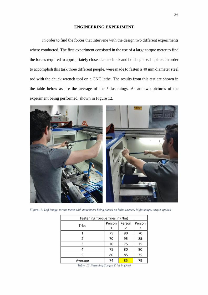
In order to find the forces that intervene with the design two different experiments
where conducted. The first experiment consisted in the use of a large torque meter to find
the forces required to appropriately close a lathe chuck and hold a piece. In place. In order
to accomplish this task three different people, were made to fasten a 40 mm diameter steel
rod with the chuck wrench tool on a CNC lathe. The results from this test are shown in
the table below as are the average of the 5 fastenings. As are two pictures of the
experiment being performed, shown in Figure 12.
Figure 18: Left image, torque meter with attachment being placed on lathe wrench. Right image, torque applied
Fastening Torque Tries in (Nm)
Tries Person
1 Person
2 Person
3
1 75 90 70
2 70 95 85
3 70 75 75
4 75 80 90
5 80 85 75
Average 74 85 79 Table 12:Fastening Torque Tries in (Nm)

37
From Table 12 the highest average value of 85 Nm was chosen to perform the calculations
necessary to choose the materials of the design, and to check design parameters. It can be
noted from the table that the values obtained from the experiments are in increments of 5
Nm. This is due to the use of a large torque meter whose characteristics are pictured below
in figure 18.
Figure 19: Torque meter wrench model specs
The second experiment performed used a small torque meter, with a minimum measuring
torque of 6Nm, and a maximum torque of 30 Nm to move the chuck itself. However, the
chuck was able to be moved with the 6 Nm from the start of the experiment. This small
torque value gives enough reason to assume that the torque needed to move the chuck is
not going to warrant mayor design considerations. This value therefore can only be used
as a reference when choosing an actuator for when the concept is to be applied.
DESIGN REPORT
The final concept prototype differs slightly from the one shown in the prototype design
section of this report. As mentioned previously, the main housing of the device was
manufactured using 3D printing as was the railing that holds the rack that is to move the
device towards the lathe chuck. This was done in order to see possible conflicts in the
geometry more clearly and correct them in a fast and cost-effective matter. All prints used
the same infill density however, (50%), with a hexagonal infill pattern and 2mm walls.

38
However, problems with 3D printing materials, and geometrical conflicts made for 3
different iterations of the design. The road map below summarizes the reasons and steps
taken in between iterations.
Road Map
1) CAD Design
a) Design of the Rack and pinion mechanism
i) Test of the rack and pinion in the software
b) Design of the Housing and the main support rail/beam
i) Design changes due to client suggestions*
2) Manufacturing of Mechanical parts
a) Search for rack and pinion in local market
i) Search unsuccessful, manufacturing required
(1) Rack and pinion machined
(2) Tool machined
(3) Wheel holder machined
b) Housing and Rail Construction**
i) PETG Selected
(1) First design rejected due to 3D printing problems
ii) PLA Selected
(1) Second design modified for functional problems***
(2) Final Design Printed.
*Initial design had 2 gears, client requested that a single gear and rack system serve as
the moving element and that NEMA actuators be used
**One 3D printing’s main advantages are the possibility to use the ease of fast
prototyping to make design iterative. Even though this method of manufacturing was
used because of the difficulty of the shapes involved in these parts, the iterative design

39
aspect of 3D printing became a big part of the design process, as it allowed for the quick
change of features in the design.
***Rail canals where too small to properly fit the housing, a fitting issue was also found
with the height of the housing, as it barely allowed for the gear to be placed in the
machine.
Figure 14 shows a general evolution of the 3 iterations of 3D printed parts in order to
further illustrate the changes that went into the design. The difference between the
iterations should be clear to identify. The first iteration, which is located on the left of the
image failed because of 3d printing mistakes. It must be noted that the rail rack for the
first iteration of the design does not have the “C” shaped rail sides, this is because the
print was stopped before these could be made, as the mistake was noted before the legs
where constructed. PETG filament which was chosen as a material for the 3D printed
parts of the prototype proved difficult to print. PETG must have a more controlled
environment and higher temperature considerations when compared to PLA.
Figure 20: The three iterations of the housing and rail rack design. On the left, the initial design; on the right, the
final design
40
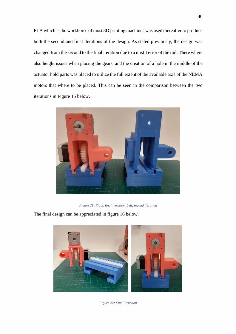
PLA which is the workhorse of most 3D printing machines was used thereafter to produce
both the second and final iterations of the design. As stated previously, the design was
changed from the second to the final iteration due to a misfit error of the rail. There where
also height issues when placing the gears, and the creation of a hole in the middle of the
actuator hold parts was placed to utilize the full extent of the available axis of the NEMA
motors that where to be placed. This can be seen in the comparison between the two
iterations in Figure 15 below.
Figure 21: Right, final iteration. Left, second iteration
The final design can be appreciated in figure 16 below.
Figure 22: Final Iteration
41
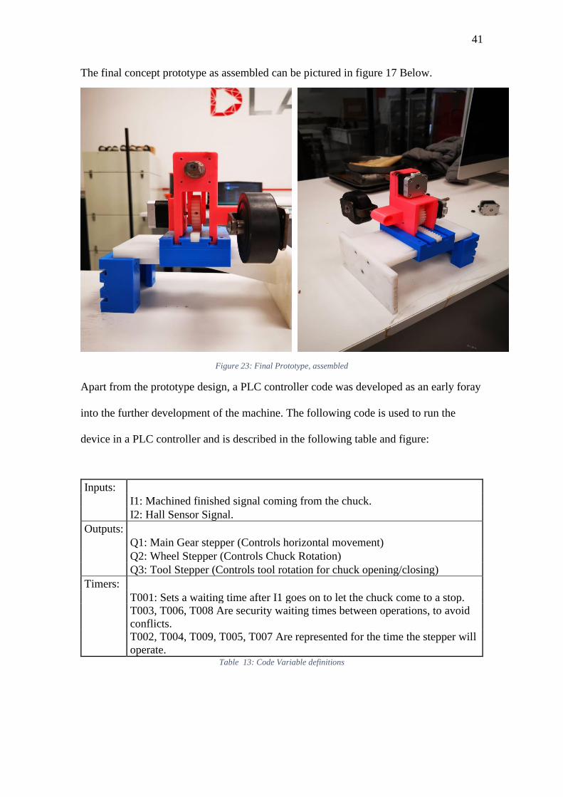
The final concept prototype as assembled can be pictured in figure 17 Below.
Figure 23: Final Prototype, assembled
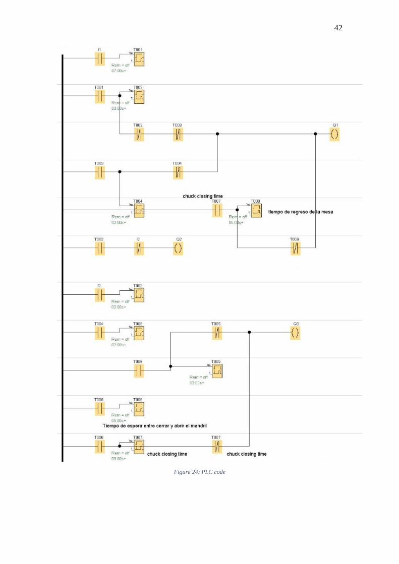
Apart from the prototype design, a PLC controller code was developed as an early foray
into the further development of the machine. The following code is used to run the
device in a PLC controller and is described in the following table and figure:
Inputs:
I1: Machined finished signal coming from the chuck.
I2: Hall Sensor Signal.
Outputs:
Q1: Main Gear stepper (Controls horizontal movement)
Q2: Wheel Stepper (Controls Chuck Rotation)
Q3: Tool Stepper (Controls tool rotation for chuck opening/closing)
Timers:
T001: Sets a waiting time after I1 goes on to let the chuck come to a stop.
T003, T006, T008 Are security waiting times between operations, to avoid
conflicts.
T002, T004, T009, T005, T007 Are represented for the time the stepper will
operate. Table 13: Code Variable definitions
42
Figure 24: PLC code

43
DISCUSSION
The concept prototype produced can open and close a chuck lathe without problem
using any controller. The tests done on the machine were meant to prove the concept of
it moving and operating a chuck. This capacity was clearly seen when the movements of
said machine where executed without flaws during testing. When the design is produced
with the materials here stated then the machine will be able to resist the loads put upon it
by the actuators. This was proven with the calculations in the materials section of the
report. The code presented in this report is also capable of running the task that the device
needs to function. One must bear in mind that this project aimed solely on producing a
concept prototype for a future machine that operates the chuck of a CNC lathe and does
so in conjunction with a bar feeding mechanism.
SAFETY THROUGH DESIGN
Safety features implemented include: The verification of spindle stoppage in the
code, which receives this signal from the lathe and waits for an average of 15 seconds to
begin operation. The rails in the design which forbid movement of the device to the sides
and hold the main body of the machine in place even while the motor is applying torque
to the chuck to close it. The machine will also automatically move back to prevent any
collision with lathe tools once it has finished closing the chuck, the lathe must also
program into its operation a code to move the tools backwards and away from the device
when finishing a part, this will minimize the threat to the machine in a very effective way.
The rail also counts with two hard stops, one in the front and one in the back, in order to
successfully stop the machine and to calibrate the distance that the rack can travel in the
pinion.

44
It must be noted that the machine in this state is not meant to be operated yet, as it is of
no use until a bar feeder attachment is made to work after the machine completes the first
action in its action list, this is why a space must be left in future design for an emergency
stop button, which, apart from turning the motors off, moves back the device and securely
puts the device away from any harm.
EXECUTIVE SUMMARY
In order to use the concept prototype to make a final product major investment,
among other things, must be considered. First it must be re-stated that the chuck opener
loses its purpose if it’s not paired with a bar feeding mechanism. It has been stated
previously that most of these are expensive, and that these are also not universal.
However, unlike with the chuck opening mechanism presented here, for which there is
no present design apart from the one in this report, a universal bar feeder design was
presented at the 28th International Conference on Flexible Automation and Intelligent
manufacturing(Silva, Campilho, Gouveia, Pinto, & Baptista, 2018). the device here
presented must be manufactured using the materials suggested in the materials section,
that being AISI 4340 steel for the tool and AISI 1018 or similar steel for the housing. The
housing is clearly the most challenging of the pieces to be manufactured, as all other
shapes are easily manufactured with machining, but it can be made using a 2 axis CNC
mill for the best precision. T shaped mills must be used in the manufacturing of this piece
for the milling of the canals.
These can be acquired through the client of this thesis, BKB, or bought online and
imported. Other manufacturing methods, such as welding can be explored by whoever

45
takes the prototype here described to manufacturing, but they must take into consideration
fatigue and design factors for this kind of manufacturing.
When selecting the correct actuators, whoever takes lead of further development must
keep in mind that the torque necessary to securely hold pieces is around 85 Nm and must
choose this to be as compact as possible, mainly because this will help with modifying
the design here presented in the least bit possible, but also because space inside a CNC
lathe is very cramped and the smaller the components the better. In the component
selection section above several different pneumatic motors has been suggested to achieve
the required torques.
In short, the concept prototype here presented completes the objective of being the first
step towards the development of a universal CNC lathe operating system. The design, and
the design concepts and lessons learned here can be applied to future development. The
materials, components, and programming of such a future development has been given
consideration in this report.

46
BIBLIOGRAPHY
Budynas, R. G., & Nisbett, J. K. (2012). Diseño en Ingenieria Mecánica de Shigley. (M.
A. Toledo Castellanos, P. E. Roig Vázquez, M. I. Rocha Martinez, M. T. Zapata
Terrazas, & Z. García García, Eds.) (9th ed.). Ciudad de Mexico: McGRAW-
HILL/Interamericana Editores, S.A. de C.V:
Bussmann, J., Granow, R., & Hammer, H. (1983). Economics of CNC lathes. Journal of
Manufacturing Systems, 2(1), 1–14. https://doi.org/10.1016/S0278-6125(83)80004-
1
Callister, W. D., & Rethwisch, D. G. (2014). Materials Science and Engineering 9th
Edition. (D. Sayre, K. Holm, & M. A. Price, Eds.) (9th ed.). Hoboken,NJ: John
Wiley & Sons Inc.
Redacción Líderes. (2016). Producción y consumo de acero mejora en la región |
Revista Líderes. Retrieved April 7, 2019, from
https://www.revistalideres.ec/lideres/produccion-consumo-acero-mejora-
region.html
Silva, F. J. G., Campilho, R. D. S. G., Gouveia, R. M., Pinto, G., & Baptista, A. (2018).
Designing a Novel Feeding System for CNC Turning Machines. Procedia
Manufacturing, 00, 1144–1153. https://doi.org/10.1016/j.promfg.2018.10.020
World Steel Association. (2018). STEEL STATISTICAL YEARBOOK 2018. Brussels.
Retrieved from https://www.worldsteel.org/en/dam/jcr:e5a8eda5-4b46-4892-856b-
00908b5ab492/SSY_2018.pdf

47
ANEXO A: PLANO EXPLOSIVO

48
ANEXO B: PROVISIONAL ARDUINO CODE
#include <Keypad.h>
// Define stepper motor connections and steps
#define dirPinM1 2
#define stepPinM1 3
#define dirPinM2 4
#define stepPinM2 5
#define stepsMotor1 110
#define stepsMotor2 2000
const byte ROWS = 4; // Four rows
const byte COLS = 4; // Three columns
char keys[ROWS][COLS] = { // Define the Keymap
{'1','4','7','*'},
{'2','5','8','0'},
{'3','6','9','#'},
{'A','B','C','D'}
};
byte rowPins[ROWS] = { 31, 32, 33, 34 };// Connect keypad ROW0, ROW1, ROW2 and ROW3 to
these Arduino pins.
byte colPins[COLS] = { 35, 36, 37 ,38}; // Connect keypad COL0, COL1 and COL2 to these Arduino
pins.
Keypad kpd = Keypad( makeKeymap(keys), rowPins, colPins, ROWS, COLS );// Create the Keypad
int Motor1Foward = 0;
void setup()
{
Serial.begin(9600);
Serial.println("Starting");
// Declare pins as output:
pinMode(stepPinM1, OUTPUT);
pinMode(dirPinM1, OUTPUT);
pinMode(stepPinM2, OUTPUT);
pinMode(dirPinM2, OUTPUT);

49
}
void loop()
{
char key = kpd.getKey();
if(key) // Check for a valid key.
{
switch (key)
{
case '1':
Serial.println("one");
// Set the spinning direction counterckwise:
digitalWrite(dirPinM1, LOW);
for (int i = 0; i < stepsMotor1; i++) {
// These four lines result in 1 step:
digitalWrite(stepPinM1, HIGH);
delayMicroseconds(3000);
digitalWrite(stepPinM1, LOW);
delayMicroseconds(3000);
}
break;
case '2':
Serial.println("two");
digitalWrite(dirPinM1, HIGH);
for (int i = 0; i < stepsMotor1; i++) {
// These four lines result in 1 step:
digitalWrite(stepPinM1, HIGH);
delayMicroseconds(3000);
digitalWrite(stepPinM1, LOW);
delayMicroseconds(3000);
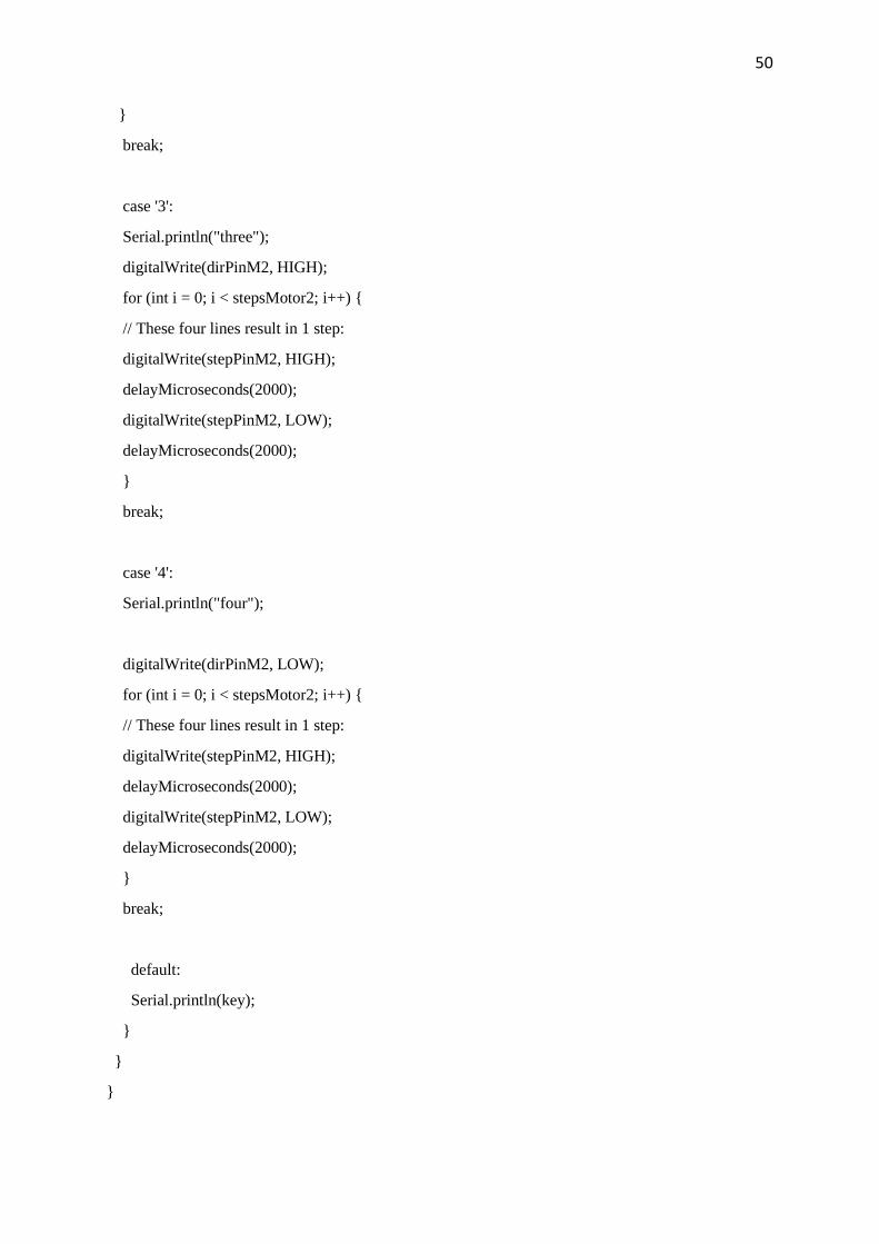
50
}
break;
case '3':
Serial.println("three");
digitalWrite(dirPinM2, HIGH);
for (int i = 0; i < stepsMotor2; i++) {
// These four lines result in 1 step:
digitalWrite(stepPinM2, HIGH);
delayMicroseconds(2000);
digitalWrite(stepPinM2, LOW);
delayMicroseconds(2000);
}
break;
case '4':
Serial.println("four");
digitalWrite(dirPinM2, LOW);
for (int i = 0; i < stepsMotor2; i++) {
// These four lines result in 1 step:
digitalWrite(stepPinM2, HIGH);
delayMicroseconds(2000);
digitalWrite(stepPinM2, LOW);
delayMicroseconds(2000);
}
break;
default:
Serial.println(key);
}
}
}
51
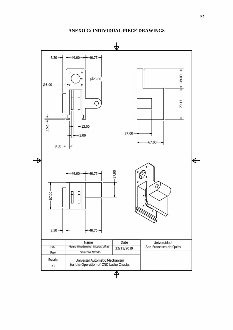
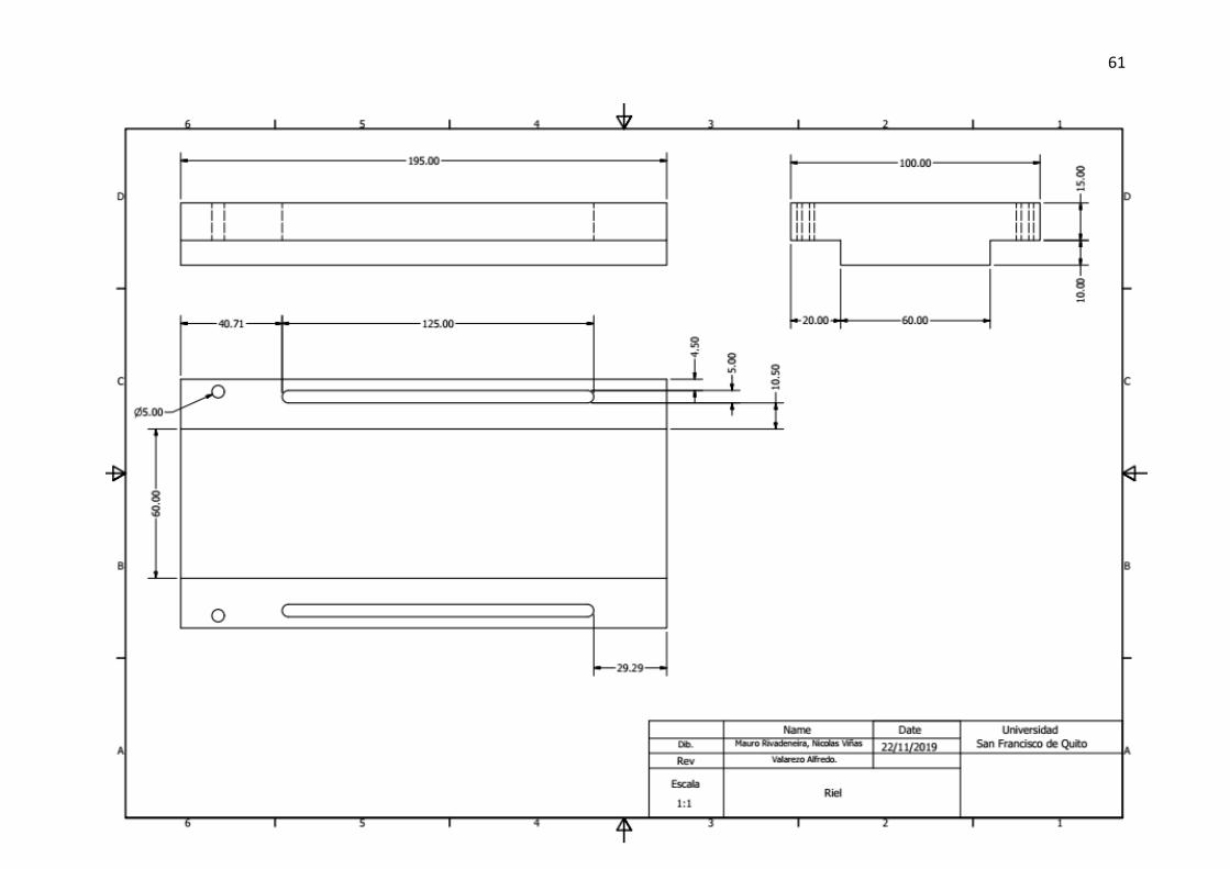
ANEXO C: INDIVIDUAL PIECE DRAWINGS

52

53
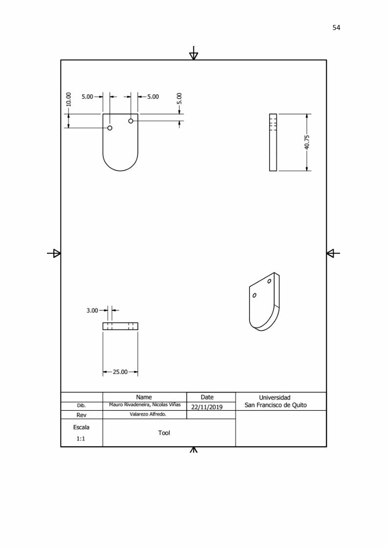
54
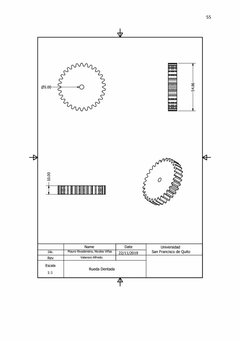
55

56
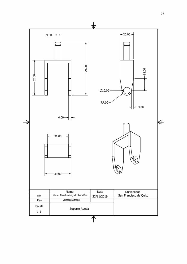
57

58

59

60
61
Related Documents