UniTrane™ Fan Coil Air Terminal Device Horizontal, Vertical, and Low Vertical Units, Size 02 to 12 June 2018 UNT-PRC001N-EN Product Catalog

Welcome message from author
This document is posted to help you gain knowledge. Please leave a comment to let me know what you think about it! Share it to your friends and learn new things together.
Transcript

UniTrane™ Fan Coil
Air Terminal DeviceHorizontal, Vertical, and Low Vertical Units, Size 02 to 12
June 2018 UNT-PRC001N-EN
Product Catalog
©2018 Ingersoll Rand UNT-PRC001N-EN
Introduction
UniTrane™ fan coils are intended for single zone applications. These units have load capabilities of 200 to 1200 cfm. Fan coils provide cooling and heating, and are available as two-pipe, with or without electric heat (one hydronic circuit) or four-pipe (two hydronic circuits). These units feature a variety of factory mounted piping packages.
Units with the variable speed fan switch only, are available with the switch mounted on the unit, or shipped separately, to be mounted in the occupied space. The variable speed switch option, which ships separately, comes with a low voltage (24 volt AC) transformer.
The Tracer® ZN010, ZN510, ZN520, and UC400-B controllers are included inside the unit’s control box assembly. These controllers utilize analog signals from a unit-mounted control device or from a control device mounted in the occupied space.
The Customer Supplied Terminal Interface (CSTI) option, includes a 24 volt AC transformer, and an interface terminal board. Controls provided by an external source can be tied into the interface terminal board utilizing the integrated terminal block with 3mm screw connections.
Copyright
This document and the information in it are the property of Trane, and may not be used or reproduced in whole or in part without written permission. Trane reserves the right to revise this publication at any time, and to make changes to its content without obligation to notify any person of such revision or change.
Trademarks
All trademarks referenced in this document are the trademarks of their respective owners.
Revision History
Updated for new offering and rearrangement of model numbers.
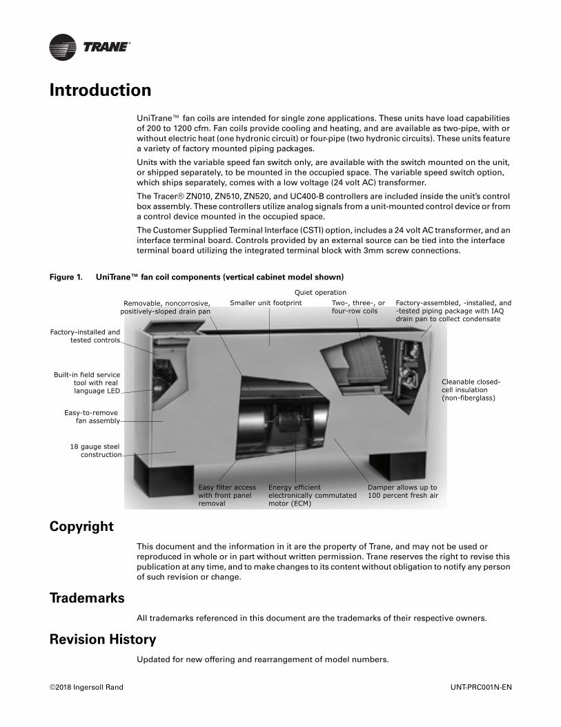
Figure 1. UniTrane™ fan coil components (vertical cabinet model shown)
Smaller unit footprint
Factory-installed andtested controls
Removable, noncorrosive,positively-sloped drain pan
Built-in field servicetool with real language LED
Easy-to-remove fan assembly
18 gauge steel construction
Easy filter accesswith front panel removal
Energy efficientelectronically commutatedmotor (ECM)
Damper allows up to 100 percent fresh air
Cleanable closed-cell insulation (non-fiberglass)
Factory-assembled, -installed, and-tested piping package with IAQ drain pan to collect condensate
Two-, three-, or four-row coils
Quiet operation
Table of Contents
Introduction . . . . . . . . . . . . . . . . . . . . . . . . . . . . . . . . . . . . . . . . . . . . . . . . . . . . . . 2
UniTrane™ Fan Coil . . . . . . . . . . . . . . . . . . . . . . . . . . . . . . . . . . . . . . . . . . . . . 5
Model Number Descriptions . . . . . . . . . . . . . . . . . . . . . . . . . . . . . . . . . . . . . . . . . 5
UniTrane™ Fan Coil Low Vertical Model . . . . . . . . . . . . . . . . . . . . . . . . . . . . 8
Features and Benefits . . . . . . . . . . . . . . . . . . . . . . . . . . . . . . . . . . . . . . . . . . . . . 10
Components and Options . . . . . . . . . . . . . . . . . . . . . . . . . . . . . . . . . . . . . . . . . . 13
Motor and Control Board . . . . . . . . . . . . . . . . . . . . . . . . . . . . . . . . . . . . . . . . 13
Factory-Installed Piping Packages . . . . . . . . . . . . . . . . . . . . . . . . . . . . . . . . . 14
Unit Configurations . . . . . . . . . . . . . . . . . . . . . . . . . . . . . . . . . . . . . . . . . . . . . . . 16
General Data . . . . . . . . . . . . . . . . . . . . . . . . . . . . . . . . . . . . . . . . . . . . . . . . . . . . . 22
Fan Coil Data . . . . . . . . . . . . . . . . . . . . . . . . . . . . . . . . . . . . . . . . . . . . . . . . . . 22
Performance Data . . . . . . . . . . . . . . . . . . . . . . . . . . . . . . . . . . . . . . . . . . . . . . . . 24
Cooling/Heating Capacity . . . . . . . . . . . . . . . . . . . . . . . . . . . . . . . . . . . . . . . . 25
Standard Capacity and High Capacity for Hot Water and Steam Reheat Coils 38
DX Cooling and Heat Pump Cooling Capacity . . . . . . . . . . . . . . . . . . . . . . . 50
Heat Pump Heating Capacity . . . . . . . . . . . . . . . . . . . . . . . . . . . . . . . . . . . . . 62
Controls . . . . . . . . . . . . . . . . . . . . . . . . . . . . . . . . . . . . . . . . . . . . . . . . . . . . . . . . 74
Why Trane Controls? . . . . . . . . . . . . . . . . . . . . . . . . . . . . . . . . . . . . . . . . . . . 74
Control Options . . . . . . . . . . . . . . . . . . . . . . . . . . . . . . . . . . . . . . . . . . . . . . . . 75
Tracer® Controllers . . . . . . . . . . . . . . . . . . . . . . . . . . . . . . . . . . . . . . . . . . . . . 77
Tracer® Controller Features . . . . . . . . . . . . . . . . . . . . . . . . . . . . . . . . . . . . . . 78
Tracer® Controls Sequence of Operation . . . . . . . . . . . . . . . . . . . . . . . . . . . 82
Air-Fi® Wireless Systems . . . . . . . . . . . . . . . . . . . . . . . . . . . . . . . . . . . . . . . . 82
Zone Sensor Options . . . . . . . . . . . . . . . . . . . . . . . . . . . . . . . . . . . . . . . . . . . 84
End Device Options . . . . . . . . . . . . . . . . . . . . . . . . . . . . . . . . . . . . . . . . . . . . . 86
Electrical Data . . . . . . . . . . . . . . . . . . . . . . . . . . . . . . . . . . . . . . . . . . . . . . . . . . . . 90
MCA and MOP Calculations . . . . . . . . . . . . . . . . . . . . . . . . . . . . . . . . . . . . . . 90
Electric Heat . . . . . . . . . . . . . . . . . . . . . . . . . . . . . . . . . . . . . . . . . . . . . . . . . . . 90
Motors . . . . . . . . . . . . . . . . . . . . . . . . . . . . . . . . . . . . . . . . . . . . . . . . . . . . . . . 91
RPM . . . . . . . . . . . . . . . . . . . . . . . . . . . . . . . . . . . . . . . . . . . . . . . . . . . . . . . . . 92
Dimensions and Weights . . . . . . . . . . . . . . . . . . . . . . . . . . . . . . . . . . . . . . . . . . 94
Service Clearances . . . . . . . . . . . . . . . . . . . . . . . . . . . . . . . . . . . . . . . . . . . . . 94
Unit Weights . . . . . . . . . . . . . . . . . . . . . . . . . . . . . . . . . . . . . . . . . . . . . . . . . 114
UNT-PRC001N-EN 3

Table of Contents
Coil Connections . . . . . . . . . . . . . . . . . . . . . . . . . . . . . . . . . . . . . . . . . . . . . . 115
Fresh Air Opening Locations . . . . . . . . . . . . . . . . . . . . . . . . . . . . . . . . . . . . 119
Mechanical Specifications . . . . . . . . . . . . . . . . . . . . . . . . . . . . . . . . . . . . . . . . . 123
Performance Data . . . . . . . . . . . . . . . . . . . . . . . . . . . . . . . . . . . . . . . . . . . . . 123
4 UNT-PRC001N-EN

Model Number Descriptions
UniTrane™ Fan Coil
Following is a complete description of the UniTrane fan coil model number. Each digit in the model number has a corresponding code that identifies specific unit options.
Note: Not all options are available on all cabinet styles. Contact your local Trane sales representative for more information.
Digits 1, 2 — Unit TypeFC = Fan Coil
Digit 3 — ModelA = Vertical concealedB = Vertical cabinetC = Horizontal concealedD = Horizontal cabinetE = Horizontal recessedH = Vertical recessedJ = Vertical slope topP = Compact concealed
Digit 4 — Development SequenceB = Development B
Digits 5, 6, 7 — Unit Cabinet Size020 = 200 cfm030 = 300 cfm040 = 400 cfm060 = 600 cfm080 = 800 cfm100 = 1000 cfm120 = 1200 cfm
Digit 8 — Unit Voltage1 = 115V/60Hz/1 phase2 = 208V/60Hz/1 phase3 = 277V/60Hz/1 phase4 = 230V/60Hz/1 phase9 = 220-240V/50Hz/1 phase
Digit 9 — Piping System/PlacementA = Without pipe, RH, without
auxiliaryB = Without pipe, LH, without
auxiliaryC = Without pipe, RH, with auxiliaryD = Without pipe, LH, with auxiliaryE = Without pipe, RH, without
auxiliary, extended endF = Without pipe, LH, without
auxiliary, extended endG = Without pipe, RH, with auxiliary,
extended endH = Without pipe, LH, with auxiliary,
extended endJ = With pipe, RHK = With pipe, LHL = With pipe, RH, extended endM = With pipe, LH, extended end
UNT-PRC001N-EN
N = Without pipe, RH, with auxiliary,extended end pipe and control
sideP = Without pipe, LH, with auxiliary,
extended end pipe and control side
Q = With pipe, RH, with auxiliary,extended end pipe and controlside
R = With pipe, LH, with auxiliary,extended end pipe and controlside
Digits 10, 11 — Design Sequence*** Factory assigned
Digit 12 — Inlet styleA = Front toe spaceB = Front bar grilleC = Front stamped louverD = Bottom stamped louverE = Bottom toe spaceF = Back duct collarG = Back exposed fanH = Back stamped louverJ = Top duct collarK = Exposed fanL = Bottom filter
Digit 13 — Outside Air Damper0 = NoneA = Manual, bottom openingB = Manual, back openingC = Manual, top openingD = Auto, 2-position, bottom
openingE = Auto, 2-position, back openingF = Auto, 2-position, top openingG = Economizer, bottom openingH = Economizer, back openingJ = Auto, economizer, top openingK = No damp, bottom openingL = No damp, back openingM = No damp, top opening
Digit 14 — Outlet styleA = Front duct collarB = Front bar grilleC = Front stamped louverD = Front quad grilleG = Top quad grilleH = Top bar grilleJ = Top duct collar
Digit 15 — Paint Cabinet Color0 = None (Units not painted)1 = Deluxe beige2 = Soft dove3 = Cameo white4 = Driftwood grey5 = Stone grey6 = Rose mauve
Digit 16 — Tamperproof Locks/Leveling Feet0 = NoneA = Locking panelB = Keylock access doorC = Locking panel, key access door,
secure grilleD = Leveling feetF = Keylock door with leveling feetG = Locking panel, key access door,
secure grille and leveling feet
Digit 17 — Motor TypesA = Free dischargeB = High static
Digit 18 — Main CoilA = 2-row cooling/heatingB = 3-row cooling/heatingC = 4-row cooling/heatingD = 2-row cooling, 1-row heatingE = 2-row cooling, 2-row heatingF = 3-row cooling, 1-row heatingG = 2-row cooling only or heating
onlyH = 3-row cooling only or heating
onlyJ = 4-row cooling only or heating
onlyK = 2-row cooling/heating, electric
heatL = 3-row cooling/heating, electric
heatM = 4-row cooling/heating, electric
heatN = Electric heat only, 1 stageP = 2-row cooling/heating,1-row
heatingQ = 2-row cooling/heating, 2-row
heatingR = 3-row cooling/heating, 1-row
heatingV = Electric heat, low kW, 1 stageX = 2-row cooling only, electric heatY = 3-row cooling only, electric heatZ = 4-row cooling only, electric heat1 = 3-row cooling, 1-row heating with
high capacity2 = 3-row cooling/heating, 1-row
heating with high capacity3 = Heat pump4 = Heat pump, auxiliary electric heat5 = DX cooling6 = DX cooling, electric preheat
Digit 19 — Drain Pan3 = Polymer drain pan4 = Stainless steel drain pan
Digit 20 — Air Vent0 = NoneA = Automatic air ventM = Manual air vent
5
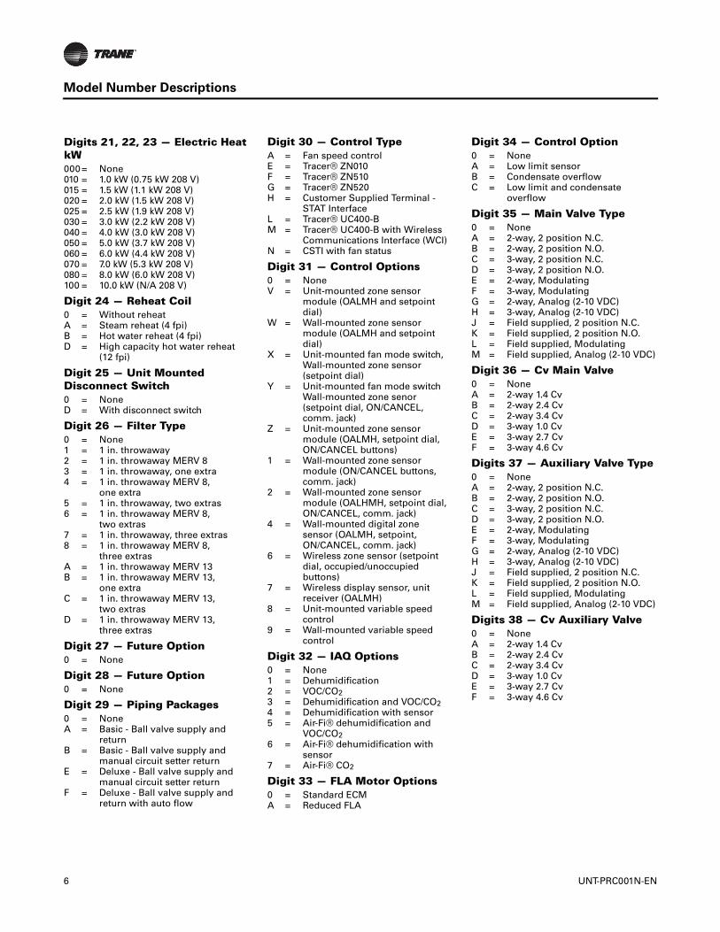
Model Number Descriptions
Digits 21, 22, 23 — Electric Heat kW000= None010 = 1.0 kW (0.75 kW 208 V)015 = 1.5 kW (1.1 kW 208 V)020 = 2.0 kW (1.5 kW 208 V)025 = 2.5 kW (1.9 kW 208 V)030 = 3.0 kW (2.2 kW 208 V)040 = 4.0 kW (3.0 kW 208 V)050 = 5.0 kW (3.7 kW 208 V)060 = 6.0 kW (4.4 kW 208 V)070 = 7.0 kW (5.3 kW 208 V)080 = 8.0 kW (6.0 kW 208 V)100 = 10.0 kW (N/A 208 V)
Digit 24 — Reheat Coil0 = Without reheatA = Steam reheat (4 fpi)B = Hot water reheat (4 fpi)D = High capacity hot water reheat
(12 fpi)
Digit 25 — Unit Mounted Disconnect Switch0 = NoneD = With disconnect switch
Digit 26 — Filter Type0 = None1 = 1 in. throwaway2 = 1 in. throwaway MERV 83 = 1 in. throwaway, one extra4 = 1 in. throwaway MERV 8,
one extra5 = 1 in. throwaway, two extras6 = 1 in. throwaway MERV 8,
two extras7 = 1 in. throwaway, three extras8 = 1 in. throwaway MERV 8,
three extrasA = 1 in. throwaway MERV 13B = 1 in. throwaway MERV 13,
one extraC = 1 in. throwaway MERV 13,
two extrasD = 1 in. throwaway MERV 13,
three extras
Digit 27 — Future Option0 = None
Digit 28 — Future Option0 = None
Digit 29 — Piping Packages0 = NoneA = Basic - Ball valve supply and
returnB = Basic - Ball valve supply and
manual circuit setter returnE = Deluxe - Ball valve supply and
manual circuit setter returnF = Deluxe - Ball valve supply and
return with auto flow
6
Digit 30 — Control TypeA = Fan speed controlE = Tracer® ZN010F = Tracer® ZN510G = Tracer® ZN520H = Customer Supplied Terminal -
STAT InterfaceL = Tracer® UC400-B M = Tracer® UC400-B with Wireless
Communications Interface (WCI)N = CSTI with fan status
Digit 31 — Control Options0 = NoneV = Unit-mounted zone sensor
module (OALMH and setpointdial)
W = Wall-mounted zone sensormodule (OALMH and setpointdial)
X = Unit-mounted fan mode switch,Wall-mounted zone sensor(setpoint dial)
Y = Unit-mounted fan mode switchWall-mounted zone senor(setpoint dial, ON/CANCEL, comm. jack)
Z = Unit-mounted zone sensormodule (OALMH, setpoint dial,ON/CANCEL buttons)
1 = Wall-mounted zone sensormodule (ON/CANCEL buttons,comm. jack)
2 = Wall-mounted zone sensormodule (OALHMH, setpoint dial,ON/CANCEL, comm. jack)
4 = Wall-mounted digital zonesensor (OALMH, setpoint, ON/CANCEL, comm. jack)
6 = Wireless zone sensor (setpointdial, occupied/unoccupiedbuttons)
7 = Wireless display sensor, unitreceiver (OALMH)
8 = Unit-mounted variable speedcontrol
9 = Wall-mounted variable speedcontrol
Digit 32 — IAQ Options0 = None1 = Dehumidification2 = VOC/CO23 = Dehumidification and VOC/CO24 = Dehumidification with sensor5 = Air-Fi® dehumidification and
VOC/CO26 = Air-Fi® dehumidification with
sensor7 = Air-Fi® CO2
Digit 33 — FLA Motor Options0 = Standard ECMA = Reduced FLA
Digit 34 — Control Option0 = NoneA = Low limit sensorB = Condensate overflowC = Low limit and condensate
overflow
Digit 35 — Main Valve Type0 = NoneA = 2-way, 2 position N.C.B = 2-way, 2 position N.O.C = 3-way, 2 position N.C.D = 3-way, 2 position N.O.E = 2-way, ModulatingF = 3-way, ModulatingG = 2-way, Analog (2-10 VDC)H = 3-way, Analog (2-10 VDC)J = Field supplied, 2 position N.C.K = Field supplied, 2 position N.O.L = Field supplied, ModulatingM = Field supplied, Analog (2-10 VDC)
Digit 36 — Cv Main Valve0 = NoneA = 2-way 1.4 CvB = 2-way 2.4 CvC = 2-way 3.4 CvD = 3-way 1.0 CvE = 3-way 2.7 CvF = 3-way 4.6 Cv
Digits 37 — Auxiliary Valve Type0 = NoneA = 2-way, 2 position N.C.B = 2-way, 2 position N.O.C = 3-way, 2 position N.C.D = 3-way, 2 position N.O.E = 2-way, ModulatingF = 3-way, ModulatingG = 2-way, Analog (2-10 VDC)H = 3-way, Analog (2-10 VDC)J = Field supplied, 2 position N.C.K = Field supplied, 2 position N.O.L = Field supplied, ModulatingM = Field supplied, Analog (2-10 VDC)
Digits 38 — Cv Auxiliary Valve0 = NoneA = 2-way 1.4 CvB = 2-way 2.4 CvC = 2-way 3.4 CvD = 3-way 1.0 CvE = 3-way 2.7 CvF = 3-way 4.6 Cv
UNT-PRC001N-EN
Model Number Descriptions
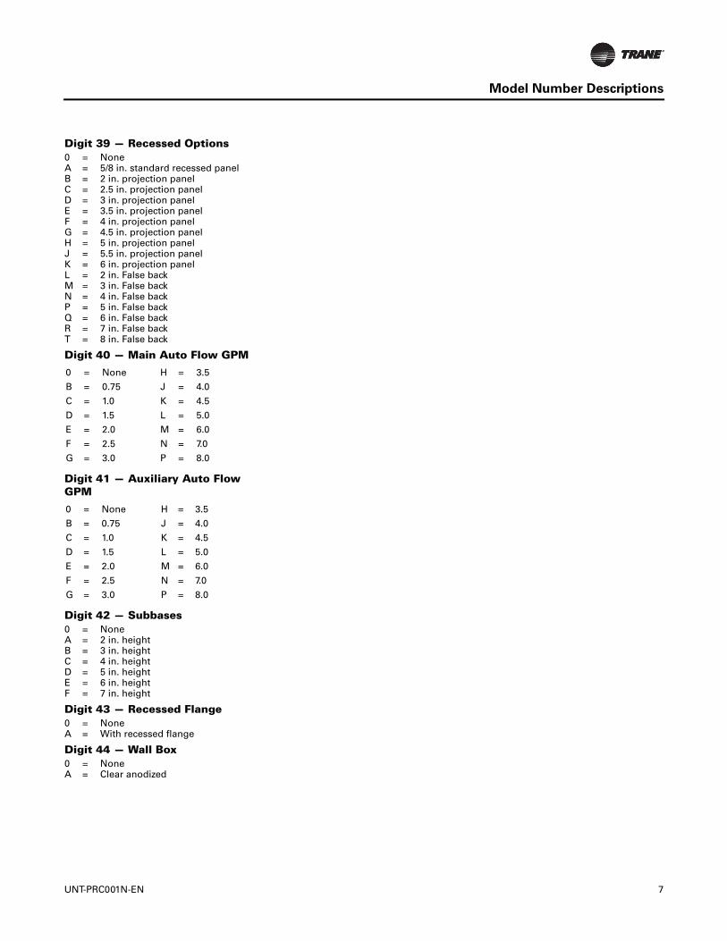
Digit 39 — Recessed Options0 = NoneA = 5/8 in. standard recessed panelB = 2 in. projection panelC = 2.5 in. projection panelD = 3 in. projection panel E = 3.5 in. projection panelF = 4 in. projection panelG = 4.5 in. projection panelH = 5 in. projection panelJ = 5.5 in. projection panelK = 6 in. projection panelL = 2 in. False backM = 3 in. False backN = 4 in. False backP = 5 in. False backQ = 6 in. False backR = 7 in. False backT = 8 in. False back
Digit 40 — Main Auto Flow GPM
Digit 41 — Auxiliary Auto Flow GPM
Digit 42 — Subbases0 = NoneA = 2 in. heightB = 3 in. heightC = 4 in. heightD = 5 in. heightE = 6 in. heightF = 7 in. height
Digit 43 — Recessed Flange0 = NoneA = With recessed flange
Digit 44 — Wall Box0 = NoneA = Clear anodized
0 = None H = 3.5
B = 0.75 J = 4.0
C = 1.0 K = 4.5
D = 1.5 L = 5.0
E = 2.0 M = 6.0
F = 2.5 N = 7.0
G = 3.0 P = 8.0
0 = None H = 3.5
B = 0.75 J = 4.0
C = 1.0 K = 4.5
D = 1.5 L = 5.0
E = 2.0 M = 6.0
F = 2.5 N = 7.0
G = 3.0 P = 8.0
UNT-PRC001N-EN
7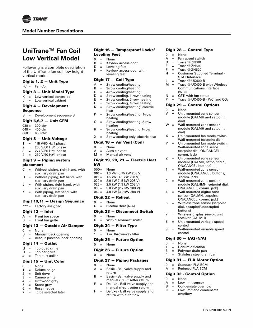
Model Number Descriptions
UniTrane™ Fan Coil
Low Vertical Model
Following is a complete description of the UniTrane fan coil low height vertical model.
Digits 1, 2 — Unit TypeFC = Fan Coil
Digit 3 — Unit Model TypeK = Low vertical concealedL = Low vertical cabinet
Digit 4 — Development SequenceB = Development sequence B
Digit 5,6,7 — Unit CFM030 = 300 cfm040 = 400 cfm060 = 600 cfm
Digit 8 — Unit Voltage1 = 115 V/60 Hz/1 phase2 = 208 V/60 Hz/1 phase3 = 277 V/60 Hz/1 phase4 = 230 V/60 Hz/1 phase
Digit 9 — Piping system placementC = Without piping, right hand, with
auxiliary drain panD = Without piping, left hand, with
auxiliary drain panJ = With piping, right hand, with
auxiliary drain panK = With piping, left hand, with
auxiliary drain pan
Digit 10,11 — Design Sequence*** = Factory assigned
Digit 12 — InletA = Front toe spaceB = Front bar grille
Digit 13 — Outside Air Damper0 = NoneB = Manual, back openingE = Auto, 2 position, back opening
Digit 14 — OutletG = Top quad grilleH = Top bar grilleJ = Top duct collar
Digit 15 — Unit Color0 = None1 = Deluxe beige2 = Soft dove3 = Cameo white4 = Driftwood grey5 = Stone grey6 = Rose mauve7 = To be selected later
8
Digit 16 — Tamperproof Locks/ Leveling Feet0 = NoneB = Keylock access doorD = Leveling feetF = Keylock access door with
leveling feet
Digit 17 — Coil TypeA = 2-row cooling/heatingB = 3-row cooling/heatingC = 4-row cooling/heatingD = 2-row cooling, 1-row heatingE = 2-row cooling, 2-row heatingF = 3-row cooling, 1-row heatingK = 2-row cooling/heating, electric
heatP = 2-row cooling/heating, 1-row
heatingQ = 2-row cooling/heating, 2-row
heatingR = 3-row cooling/heating,1-row
heatingX = 2-row cooling only, electric heat
Digit 18 — Air Vent (Coil)0 = NoneA = Auto air ventM = Manual air vent
Digit 19, 20, 21 — Electric Heat kW000= None010 = 1.0 kW (0.75 kW 208 V)015 = 1.5 kW (1.1 kW 208 V)020 = 2.0 kW (1.5 kW 208 V)025 = 2.5 kW (1.9 kW 208 V)030 = 3.0 kW (2.2 kW 208 V)040 = 4.0 kW (3.0 kW 208 V)
Digit 22 — Reheat0 = NoneC = Electric Heat (N/A)
Digit 23 — Disconnect Switch0 = NoneD = With disconnect switch
Digit 24 — Filter Type0 = None1 = 1 in. throwaway filter
Digit 25 — Future Option0 = None
Digit 26 — Future Option0 = None
Digit 27 — Piping Packages0 = NoneA = Basic - Ball valve supply and
returnB = Basic - Ball valve supply and
manual circuit setter returnE = Deluxe - Ball valve supply and
manual circuit setter returnF = Deluxe - Ball valve supply and
return with auto flow
Digit 28 — Control Type0 = NoneA = Fan speed switchD = Tracer® ZN010E = Tracer® ZN510F = Tracer® ZN520H = Customer Supplied Terminal -
STAT InterfaceL = Tracer® UC400-B M = Tracer® UC400-B with Wireless
Communications Interface(WCI)
N = CSTI with fan statusP = Tracer® UC400-B - WCI and CO2
Digit 29 — Control Options0 = NoneV = Unit-mounted zone sensor
module (OALMH and setpointdial)
W = Wall-mounted zone sensormodule (OALMH and setpointdial)
X = Unit-mounted fan mode switch,Wall-mounted (setpoint dial)
Y = Unit-mounted fan mode switch,Wall-mounted zone senor(setpoint dial, ON/CANCEL, comm. jack)
Z = Unit-mounted zone sensormodule (OALMH, setpoint dial,ON/CANCEL buttons)
1 = Wall-mounted zone sensormodule (ON/CANCEL buttons, comm. jack)
2 = Wall-mounted zone sensormodule (OALHMH, setpoint dial,ON/CANCEL, comm. jack)
4 = Wall-mounted digital zonesensor (OALMH, setpoint, ON/CANCEL, comm. jack)
6 = Wireless zone sensor (setpointdial, occupied/unoccupiedbuttons)
7 = Wireless display sensor, unitreceiver (OALMH)
8 = Unit-mounted variable speedcontrol
9 = Wall-mounted variable speedcontrol
Digit 30 — IAQ (N/A)0 = None1 = Dehumidification3 = Polymer drain pan4 = Stainless steel drain pan
Digit 31 — FLA Motor Option0 = Standard FLA ECMA = Reduced FLA ECM
Digit 32 - Control Option0 = NoneA = Low limit sensorB = Condensate overflowC = Low limit and condensate
overflow
UNT-PRC001N-EN

Model Number Descriptions
Digit 33 — Main Valve Type0 = NoneA = 2-way, 2 position N.C.B = 2-way, 2 position N.O.C = 3-way, 2 position N.C.D = 3-way, 2 position N.O.E = 2-way, ModulatingF = 3-way, ModulatingG = 2-way, Analog (2-10 VDC)H = 3-way, Analog (2-10 VDC)J = Field supplied, 2 position N.C.K = Field supplied, 2 position N.O.L = Field supplied, ModulatingM = Field supplied, Analog (2-10 VDC)
Digit 34 — Cv Main Valve0 = NoneA = 2-way 1.4 CvB = 2-way 2.4 CvC = 2-way 3.4 CvD = 3-way 1.0 CvE = 3-way 2.7 Cv
Digits 35 — Auxiliary Valve Type0 = NoneA = 2-way, 2 position N.C.B = 2-way, 2 position N.O.C = 3-way, 2 position N.C.D = 3-way, 2 position N.O.E = 2-way, ModulatingF = 3-way, ModulatingG = 2-way, Analog (2-10 VDC)H = 3-way, Analog (2-10 VDC)J = Field supplied, 2 position N.C.K = Field supplied, 2 position N.O.L = Field supplied, ModulatingM = Field supplied, Analog (2-10 VDC)
Digits 36 — Cv Auxiliary Valve0 = NoneA = 2-way 1.4 CvB = 2-way 2.4 CvC = 2-way 3.4 CvD = 3-way 1.0 CvE = 3-way 2.7 Cv
Digit 37 — Main Auto Flow GPM0 = NoneA = 0.75B = 1.0C = 1.5D = 2.0E = 2.5F = 3.0G = 3.5H = 4.0J = 4.5
UNT-PRC001N-EN
Digit 38 — Auxiliary Auto Flow GPM0 = NoneA = 0.75B = 1.0C = 1.5D = 2.0E = 2.5F = 3.0G = 3.5H = 4.0J = 4.5
9
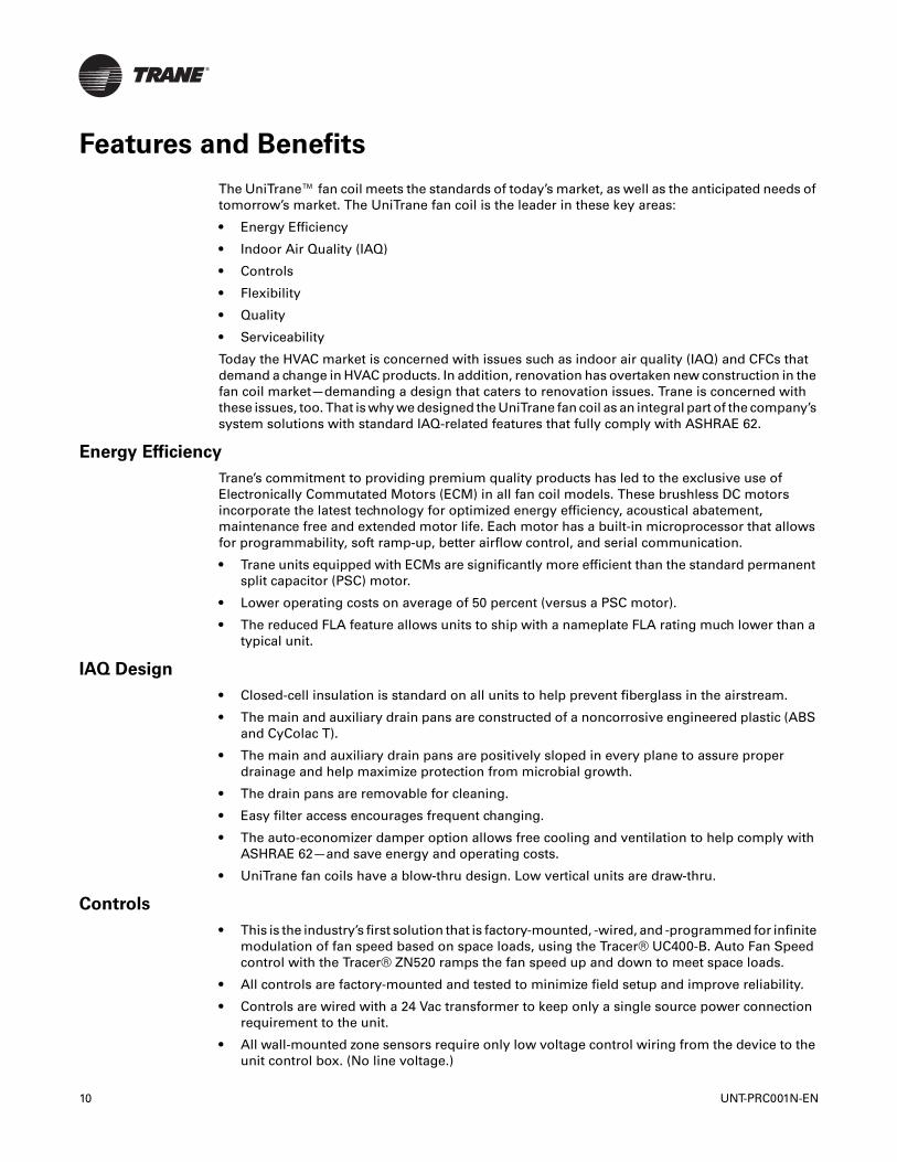
Features and Benefits
The UniTrane™ fan coil meets the standards of today’s market, as well as the anticipated needs of tomorrow’s market. The UniTrane fan coil is the leader in these key areas:
• Energy Efficiency
• Indoor Air Quality (IAQ)
• Controls
• Flexibility
• Quality
• Serviceability
Today the HVAC market is concerned with issues such as indoor air quality (IAQ) and CFCs that demand a change in HVAC products. In addition, renovation has overtaken new construction in the fan coil market—demanding a design that caters to renovation issues. Trane is concerned with these issues, too. That is why we designed the UniTrane fan coil as an integral part of the company’s system solutions with standard IAQ-related features that fully comply with ASHRAE 62.
Energy Efficiency
Trane’s commitment to providing premium quality products has led to the exclusive use of Electronically Commutated Motors (ECM) in all fan coil models. These brushless DC motors incorporate the latest technology for optimized energy efficiency, acoustical abatement, maintenance free and extended motor life. Each motor has a built-in microprocessor that allows for programmability, soft ramp-up, better airflow control, and serial communication.
• Trane units equipped with ECMs are significantly more efficient than the standard permanent split capacitor (PSC) motor.
• Lower operating costs on average of 50 percent (versus a PSC motor).
• The reduced FLA feature allows units to ship with a nameplate FLA rating much lower than a typical unit.
IAQ Design
• Closed-cell insulation is standard on all units to help prevent fiberglass in the airstream.
• The main and auxiliary drain pans are constructed of a noncorrosive engineered plastic (ABS and CyColac T).
• The main and auxiliary drain pans are positively sloped in every plane to assure proper drainage and help maximize protection from microbial growth.
• The drain pans are removable for cleaning.
• Easy filter access encourages frequent changing.
• The auto-economizer damper option allows free cooling and ventilation to help comply with ASHRAE 62—and save energy and operating costs.
• UniTrane fan coils have a blow-thru design. Low vertical units are draw-thru.
Controls
• This is the industry’s first solution that is factory-mounted, -wired, and -programmed for infinite modulation of fan speed based on space loads, using the Tracer® UC400-B. Auto Fan Speed control with the Tracer® ZN520 ramps the fan speed up and down to meet space loads.
• All controls are factory-mounted and tested to minimize field setup and improve reliability.
• Controls are wired with a 24 Vac transformer to keep only a single source power connection requirement to the unit.
• All wall-mounted zone sensors require only low voltage control wiring from the device to the unit control box. (No line voltage.)
10 UNT-PRC001N-EN
Features and Benefits
• The controller automatically determines the unit’s correct operating mode (heat/cool) by utilizing a proportional/integral (PI) control algorithm to maintain the space temperature at the active setpoint, allowing total comfort control.
• Entering water temperature sampling eliminates the need for inefficient bleedlines to sense automatic changeover on two-pipe changeover units.
• The random start-up feature helps reduce electrical demand peaks by randomly staggering multiple units at start-up.
• Occupied/unoccupied operation allows the controller to utilize unoccupied temperature setpoints for energy savings.
• Warm-up and cool-down energy features are standard with Trane controls.
• Continuous fan or fan cycling is available with Tracer® ZN010 or ZN510.
• Monitor unit operation using Tracer® TU building management system with Tracer® ZN510 or ZN520 and UC400-B.
• To customize unit control, Tracer® TU or Rover™ software will allow field modification of Tracer® ZN510 and ZN520 default settings. Tracer® ZN010 uses Rover to field modify default settings. UC400-B uses Tracer® TU.
• Maximize fan coil system efficiency with free cooling economizers and modulating valves on units with Tracer® ZN520 and UC400-B.
Flexibility
• Two, three, and four-row coils allow greater design flexibility in two and four-pipe systems.
• One-row steam or hot water reheat coils for dehumidification on units with ZN520 controls.
• Fan motors are available for either high static (0.4-inch external static pressure) or free discharge applications.
• Piping is factory assembled, mounted and tested. Units are also available without piping. Reheat coil piping is available on 2-pipe units with hot water reheat coils and either a fan speed switch or Tracer® ZN520 and UC400-B.
• Control options range from a simple fan speed switch to a DDC controller that can tie into a Tracer® Summit building automation system.
• An 8-inch extended end pocket is available on the piping end of cabinet style units. An additional 8-inch extended end pocket is also available on the controls end of the cabinet style units.
• Slope-top vertical cabinet units are also available for school and dormitory applications to prevent items from being placed on top of the units.
Quality
• Coils and piping packages are air and leak-tested before mounting on the fan coil.
• Coil piping connections are also air and leak-tested after mounting on the unit.
• All control end devices and moving components (fans and motors) are computer-tested after units are complete.
UNT-PRC001N-EN 11

Features and Benefits
Serviceability
• Touch-safe control box.
• Integrated user interface with real language LED display.
• Built-in tachometer.
• Filters are easily removable and changed without removing the front panel on vertical cabinet units.
• Motors are easy to disconnect from the fan board, allowing easy service.
• The main and auxiliary drain pans are easily removable and wipe clean with a wet cloth.
• The manual output test function is an invaluable troubleshooting tool. By simply pressing the test button on the Tracer® ZN510, ZN520, or ZN010; service personnel can manually exercise outputs in a pre-defined sequence.
12 UNT-PRC001N-EN

Components and Options
Motor and Control Board
• Trane Electronically Commutated Motor (ECM)
• VelociTach™ motor control board
The motor and control board are combined as a system, and cannot work without each other. This new series delivers outstanding comfort, safety, and performance with greatly reduced energy consumption compared to traditional units.
Electronically Commutated Motor (ECM)
VelociTach™ Motor Control Board
The VelociTach motor control board controls and reports the performance of up to two Trane brushless DC (BLDC) motors.
Status Display
• The ECM has integrated electronics, overload protection and short circuit protection. The motor contains no user-serviceable components inside.
• The motor mates to the unit electrically via a single plug that contains both the operating voltage and the control signals that are needed for correct operation.
The motor control board also:
• Coordinates the operation of the fan in response to electric heat behavior and electric behavior in response to hydronic heat behavior.
• Incorporates a user interface that allows adjustment of certain unit parameters and provides constant feedback on motor operation.
• Integrates service and troubleshooting tools.
• Integrates a versatile configurable auxiliary temperature sensor.
• Incorporates various safety and lockout features, such as maintaining proper fan speeds if electric heat is called for.
The motor control board contains a four-digit, seven-segment display that is used to present information in a format close to real-world language, while having a small-form factor. Most characters are immediately recognizable; however, please refer the following screen representation of alphabetical characters and numeric characters tables below.
UNT-PRC001N-EN 13
Components and Options
Factory-Installed Piping Packages
Standard piping packages are available as a factory-built and installed option. Piping package options are also available for the hot water reheat coil on two-pipe units equipped with either a fan speed switch or Tracer® ZN520 and UC400-B controller. Factory built assures all piping packages are fully tested under water for leaks and are built within strict tolerances. Factory-installed means that chilled and hot water pipes are the only field connections required. The installer doesn’t have to sweat connect piping packages onto coil connections in a tight end pocket. Field connections are brought to a point near the exterior of the unit for easy access. All piping and components are located to allow condensate to drain into the auxiliary drain pan. Insulation of the factory piping package is not required. However, all field connections should be insulated to prevent condensation from missing the auxiliary drain pan.
Piping Package Components
Control valves are mounted in all factory piping packages. All piping packages are factory installed and come in a variety of options:
• Basic: Shut-off ball valve on the supply line. Control valve and shut-off ball valve on the return line.
• Basic with Manual circuit setter: Shut-off ball valve on the supply line. Control valve and manual circuit setter on the return line.
• Deluxe with Manual circuit setter: Union, strainer, P/T port, and shut-off ball valve on the supply line. Union, control valve and manual circuit setter on the return line.
• Deluxe with auto flow: Union, strainer, P/T port, and shut-off ball valve on the supply line. Union, control valve, auto flow valve, P/T port and shut-off ball valve on the return line.
Piping System/Placement
Factory piping systems are available for either two or four-pipe systems with right or left hand connections. Four-pipe systems have both the heating and cooling connections on the same side of the unit. A simple coil connection (a unit without a piping package) is also available in either a right or left hand configuration for those applications requiring field piping.
Interconnecting Piping
Interconnecting piping refers to the copper piping which is attached to the coil connections and to which all other components (control valves, end valves, etc.) are attached. Piping is 1/2” nominal OD copper. Two-pipe piping extends near the unit exterior to one inlet and one outlet connection. Four-pipe units have two sets of piping that extend near the unit exterior — one inlet and one outlet each for both chilled and hot water. A label clearly identifies chilled and hot water connection points on every unit.
Table 1. Screen representation of alphabetical characters
A B C D E F G H I J K L M N O P Q R S T U V W X Y Z
A B C D E F G H I J K L M N O P Q R S T U V W X Y Z
Table 2. Screen representation of numeric characters
1 2 3 4 5 6 7 8 9 0
1 2 3 4 5 6 7 8 9 0
14 UNT-PRC001N-EN

Components and Options
Figure 2. Piping package arrangements
Basic
Basic with manual circuit setter
2-way
2-way
3-way
3-way
2-way main orauxilliary water valve
Ball valve
Returnconnection
Ball valve
Supply connection
3-way main orauxilliary water valve
Ball valve
Supplyconnection
Ball valveReturn connection
3-way main orauxilliary water valve
Ball valve
Returnconnection
Supply connection
2-way main orauxilliary water valve
Ball valve
Returnconnection
Circuit setter
Supply connection
Typical coil
Balancingfitting
Typical coilTypicalcoil
Balance fitting
Typical coil
Circuitsetter
Deluxe with manual circuit setter
Deluxe with auto flow
2-way main orauxilliary water valve
2-way main orauxilliary water valve
3-way main orauxilliary water valve
Circuit setter
Supplyconnection
Supplyconnection
Supplyconnection
Returnconnection
Returnconnection
Returnconnection
2-way
2-way
3-way
3-way
Circuitsetter
Ball valve
P/T port StrainerUnion
Typical coil Typicalcoil
Typical coil
Union Union
Union
Union
Union
P/T port
P/T port
Strainer
Strainer
Ball valve
Ball valve
Ball valve
P/T port
Autoflow
Balancing fitting
3-way main orauxilliary water valve
Supplyconnection
ReturnconnectionTypical
coil
Union
Union
P/T portStrainer
Ball valve
Autoflow P/T port
Balancing fitting
Ball valve
UNT-PRC001N-EN 15
Unit Configurations
Unit Configurations
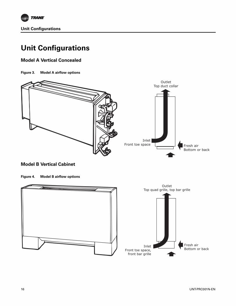
Model A Vertical Concealed
Model B Vertical Cabinet
Figure 3. Model A airflow options
OutletTop duct collar
Fresh airBottom or back
InletFront toe space
Figure 4. Model B airflow options
OutletTop quad grille, top bar grille
Fresh airBottom or back
InletFront toe space,
front bar grille
16 UNT-PRC001N-EN
Unit Configurations
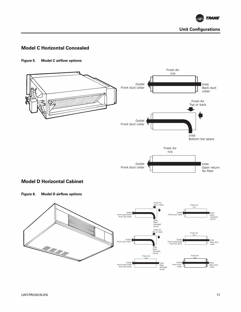
Model C Horizontal Concealed
Model D Horizontal Cabinet
Figure 5. Model C airflow options
OutletFront duct collar
Fresh AirTop or back
InletBottom toe space
Fresh Airn/a
InletBack duct collar
OutletFront duct collar
Fresh Airn/a
InletOpen returnNo filter
OutletFront duct collar
Figure 6. Model D airflow options
Fresh Airn/a
InletBack duct collar
OutletFront quad grille
Front bar grille
Fresh Airn/a
InletBack stamped louver
OutletFront duct collar
OutletFront quad grille
Front bar grille
Fresh AirTop or back
InletBack stamped louver
OutletFront quad grille
Front bar grille
InletBack stampedlouver
Fresh Airn/a
OutletFront duct collar
Fresh AirTop or back
InletBack stamped louver
Fresh Airn/a
InletBack duct collar
OutletFront duct
collar
UNT-PRC001N-EN 17
Unit Configurations
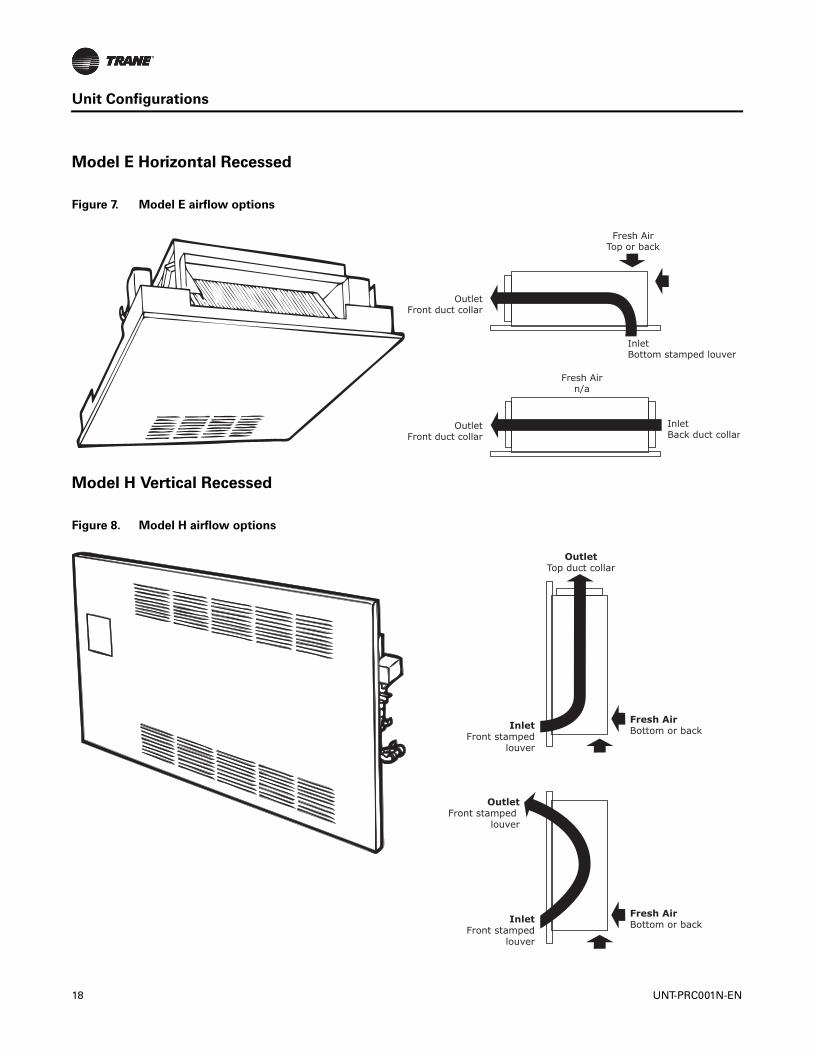
Model E Horizontal Recessed
Model H Vertical Recessed
Figure 7. Model E airflow options
Fresh Airn/a
OutletFront duct collar
InletBack duct collar
OutletFront duct collar
InletBottom stamped louver
Fresh AirTop or back
Figure 8. Model H airflow options
Fresh AirBottom or backInlet
Front stampedlouver
OutletFront stamped
louver
InletFront stamped
louver
Fresh AirBottom or back
OutletTop duct collar
18 UNT-PRC001N-EN
Unit Configurations
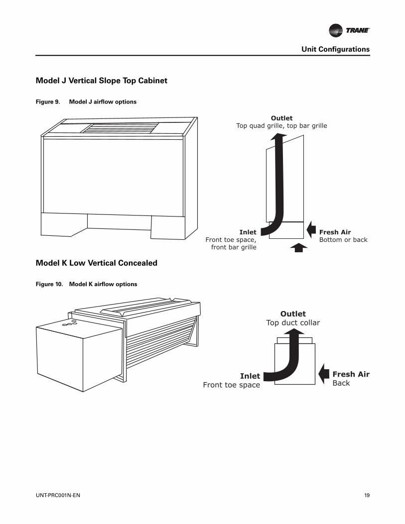
Model J Vertical Slope Top Cabinet
Model K Low Vertical Concealed
Figure 9. Model J airflow options
OutletTop quad grille, top bar grille
Fresh AirBottom or back
InletFront toe space,
front bar grille
Figure 10. Model K airflow options
OutletTop duct collar
Fresh AirBack
InletFront toe space
UNT-PRC001N-EN 19
Unit Configurations
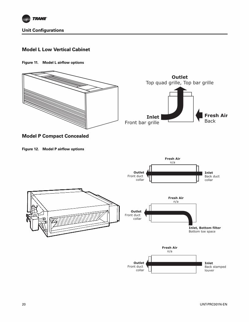
Model L Low Vertical Cabinet
Model P Compact Concealed
Figure 11. Model L airflow options
OutletTop quad grille, Top bar grille
Fresh AirBack
InletFront bar grille
Figure 12. Model P airflow options
Fresh Airn/a
InletBack stamped louver
OutletFront duct
collar
OutletFront duct
collar
Fresh Airn/a
Inlet, Bottom filterBottom toe space
Fresh Airn/a
InletBack duct collar
OutletFront duct
collar
20 UNT-PRC001N-EN

Unit Configurations
Model P Compact Concealed with Recessed Panel Option
Figure 13. Model P with recessed panel airflow options
Fresh Airn/a
OutletFront duct collar
InletBack duct collar
OutletFront duct collar
Inlet, Bottom filterBottom stamped louver
Fresh Airn/a
Fresh Airn/a
Inlet, Exposed fanOpen return,No filter
OutletFront duct collar
UNT-PRC001N-EN 21

General Data
Fan Coil Data
Table 3. Fan coil component data
Unit Size 02 03 04 06 08 10 12Coil DataFace Area (ft2) 0.80 0.80 1.10 1.60 2.10 3.20 3.20L x D x H (in.)
2-Row 15 x 1.7 x 8 15 x 1.7 x 8 20 x 1.7 x 8 29.5 x 1.7 x 8 38 x 1.7 x 8 57 x 1.7 x 8 57 x 1.7 x 83-Row 15 x 2.6 x 8 15 x 2.6 x 8 20 x 2.6 x 8 29.5 x 2.6 x 8 38 x 2.6 x 8 57 x 2.6 x 8 57 x 2.6 x 84-Row 15 x 3.5 x 8 15 x 3.5 x 8 20 x 3.5 x 8 29.5 x 3.5 x 8 38 x 3.5 x 8 57 x 3.5 x 8 57 x 3.5 x 8
Volume (gal.)1-Row (Heat) 0.06 0.06 0.08 0.11 0.14 0.21 0.212-Row 0.12 0.12 0.15 0.22 0.28 0.42 0.423-Row 0.18 0.18 0.23 0.33 0.42 0.62 0.624-Row 0.24 0.24 0.30 0.44 0.56 0.83 0.83
Refrigerant volume (cubic in.) 3-Row ---- ---- ---- 76.23 97.02 143.22 ---- 4-Row ---- ---- ---- ---- ---- ---- 191.73Fins per inch
2-Row 12 12 12 12 12 12 123-Row 12 12 12 12 12 12 12
3/1-Row high capacity 16 16 16 16 16 16 164-Row 12 12 12 12 12 12 12
Reheat Coil Data (1-Row), Standard or High-Capacity1
Hot Water or SteamFace Area (ft2) 0.60 0.60 0.80 1.20 1.60 2.40 2.40L x D x H (in.) 15 x 1.5 x 6 15 x 1.5 x 6 20 x 1.5 x 6 29.5 x 1.5 x 6 38 x 1.5 x 6 57 x 1.5 x 6 57 x 1.5 x 6Volume (gal.) 0.12 0.12 0.15 0.22 0.28 0.42 0.42 Std Capacity1 Fins/in. 4 4 4 4 4 4 4High-Capacity1 Fins/in. 12 12 12 12 12 12 12Fan/Motor DataFan Quantity 1 1 1 2 2 3 3Size-Dia x Width (in.) 6.31 x 4 6.31 x 6.5 6.31 x 7.5 6.31 x 6.5 6.31 x 7.5 (1) 6.31 x 7.5 6.31 x 7.5 Size-Dia x Width (in.) (2) 6.31 x 6.5 Motor Quantity 1 1 1 1 1 2 2Filter Data1-in. Throwaway and Pleated MediaQuantity 1 1 1 1 1 1 1Size (in.) 8-7/8 x 19-1/8 8-7/8 x 19-1/8 8-7/8 x 24-1/8 8-7/8 x 33-5/8 8-7/8 x 42-1/8 8-7/8 x 61-1/8 8-7/8 x 61-1/8 1-in. Fresh Air Filter (only on cabinet styles D, E, and H with bottom return and fresh air opening)Quantity 1 1 1 1 1 1 1Size (in.) 5-1/2 x 19-1/8 5-1/2 x 19-1/8 5-1/2 x 24-1/8 5-1/2 x 33-5/8 5-/2 x 42-1/8 5-1/2 x 61-1/8 5-1/2 x 61-1/8 Note: 1Standard and high-capacity reheat coils share the same component data except that standard capacity reheat coils have 4 fins/in. while high-capacity
reheat coils have 12 fpi.
Table 4. Low vertical fan coil component data
Unit Size 03 04 06Coil DataFace Area (ft2) 1.10 1.60 2.10L x D x H (in.)
2-Row 20 x 1.7 x 8 29.5 x 1.7 x 8 38 x 1.7 x 83-Row 20 x 2.6 x 8 29.5 x 2.6 x 8 38 x 2.6 x 8
22 UNT-PRC001N-EN

General Data
Volume (gal.)1-Row (Heat) 0.08 0.11 0.142-Row 0.15 0.22 0.283-Row 0.23 0.33 0.42
Fins per inch2-Row 12 12 123-Row 12 12 12
Fan/Motor DataFan Quantity 1 1 1Size — Dia x Width (in.) 5.00 x 23.00 5.00 x 32.00 5.00x 41.00Motor Quantity 1 1 1Filter Data1-in. ThrowawayQuantity 1 1 1Size — in. 8-7/8 x 24-1/8 8-7/8 x 33-5/8 8-7/8 x 42-1/8 Note: Low vertical model not available for Force Flo cabinet heaters.
Table 4. Low vertical fan coil component data (continued)
Unit Size 03 04 06
Table 5. Fan coil air flow (cfm), hydronic only
FC Coil
External Static Pressure (ESP)FD High Static
0.05 0.10 0.20 0.30 0.40
022-row 246 344 314 283 2513-row 242 352 319 284 2494-row 222 326 295 263 230
032-row 313 410 380 350 3193-row 309 391 358 324 2904-row 276 360 330 299 267
042-row 381 446 410 373 3363-row 365 544 506 467 4274-row 340 506 470 434 397
062-row 609 757 700 642 5823-row 604 880 824 766 7074-row 557 812 760 706 652
082-row 790 1014 950 885 8193-row 724 992 927 861 7944-row 676 930 870 808 745
102-row 1015 1284 1199 1113 10243-row 1052 1456 1360 1262 11624-row 988 1366 1276 1183 1089
122-row 1105 1424 1330 1234 11343-row 1074 1514 1419 1320 12194-row 993 1421 1330 1238 1144
UNT-PRC001N-EN 23
Performance Data
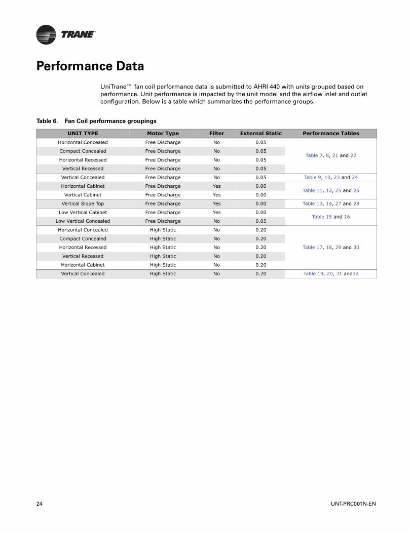
UniTrane™ fan coil performance data is submitted to AHRI 440 with units grouped based on performance. Unit performance is impacted by the unit model and the airflow inlet and outlet configuration. Below is a table which summarizes the performance groups.
Table 6. Fan Coil performance groupings
UNIT TYPE Motor Type Filter External Static Performance Tables
Horizontal Concealed Free Discharge No 0.05
Table 7, 8, 21 and 22Compact Concealed Free Discharge No 0.05
Horizontal Recessed Free Discharge No 0.05
Vertical Recessed Free Discharge No 0.05
Vertical Concealed Free Discharge No 0.05 Table 9, 10, 23 and 24
Horizontal Cabinet Free Discharge Yes 0.00Table 11, 12, 25 and 26
Vertical Cabinet Free Discharge Yes 0.00
Vertical Slope Top Free Discharge Yes 0.00 Table 13, 14, 27 and 28
Low Vertical Cabinet Free Discharge Yes 0.00Table 15 and 16
Low Vertical Concealed Free Discharge No 0.05
Horizontal Concealed High Static No 0.20
Table 17, 18, 29 and 30
Compact Concealed High Static No 0.20
Horizontal Recessed High Static No 0.20
Vertical Recessed High Static No 0.20
Horizontal Cabinet High Static No 0.20
Vertical Concealed High Static No 0.20 Table 19, 20, 31 and32
24 UNT-PRC001N-EN

Performance Data
Cooling/Heating Capacity
Horizontal Concealed, Compact Concealed, Horizontal Recessed, and Vertical Recessed
AHRI cooling performance is based on 80/67°F entering air temperature, 45°F entering chilled water temperature with a 10°F ΔT.
Heating performance is based on 70°F entering air temperature, 180°F entering hot water temperature with a 30°F ΔT.
All performance measured on high speed tap, 115 V, 0.05 ESP, without filter. Free discharge EC motor.
Table 7. Cooling/Heating capacity - 2-pipe performance—free discharge EC motor
Size CoilAirflow (cfm)
Cooling Heating
Motor Power (W)
Total Capacity(MBh)
Sensible Capacity
Flow Rate
(gpm)WPD
(ft H20)
Total Capacity(MBh) Q/ITD
Flow Rate
(gpm)WPD
(ft H20)
020
2HC 246 5.93 4.38 1.20 8.01 16.67 0.15 1.10 5.36 37
3HC 242 6.79 5.01 1.40 2.87 20.14 0.18 1.30 2.26 37
4HC 222 8.15 5.55 1.70 5.03 21.47 0.20 1.40 3.18 37
030
2HC 313 6.71 5.07 1.40 9.90 16.62 0.18 1.30 7.15 39
3HC 309 7.96 5.98 1.60 3.81 24.16 0.22 1.60 3.15 39
4HC 276 9.51 6.56 1.90 6.59 25.69 0.23 1.70 4.39 39
040
2HC 381 8.47 6.76 1.70 3.55 23.99 0.22 1.60 2.61 58
3HC 365 11.36 8.03 2.30 8.21 30.03 0.27 2.00 5.29 58
4HC 340 12.76 8.52 2.60 12.80 32.46 0.30 2.20 7.63 58
060
2HC 609 14.73 11.13 3.00 11.56 38.28 0.35 2.60 7.34 79
3HC 604 16.49 12.37 3.30 4.43 47.33 0.43 3.20 3.60 79
4HC 557 19.16 13.20 3.90 6.90 51.53 0.47 3.40 4.88 79
080
2HC 790 16.11 13.12 3.30 3.83 48.08 0.44 3.20 3.35 122
3HC 724 20.50 14.61 4.20 7.41 58.69 0.53 3.90 5.89 122
4HC 676 22.59 15.32 4.60 10.55 69.94 0.58 4.30 8.08 122
100
2HC 1015 25.90 19.29 5.30 10.84 66.92 0.61 4.50 7.22 145
3HC 1052 31.14 22.21 6.30 11.09 85.99 0.78 5.70 8.81 145
4HC 988 36.48 24.00 7.40 14.94 94.57 0.86 6.30 10.19 145
120
2HC 1105 26.94 20.19 5.50 11.69 70.87 0.64 4.70 8.05 160
3HC 1074 31.39 22.40 6.40 11.29 87.33 0.79 5.80 9.08 160
4HC 993 36.46 23.99 7.40 14.96 94.96 0.86 6.30 10.27 160
Note: Q/ITD = MBh (kW)/(Entering water temperature - Entering air temperature) when ∆T and gpm (L/s) remain constant. To determine heating capacities at a different entering water temperature or entering air temp, compute the new ITD and multiply it by the Q/ITD shown.
UNT-PRC001N-EN 25
Performance Data
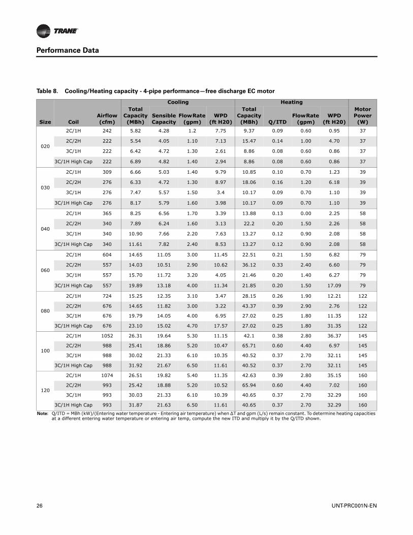
Table 8. Cooling/Heating capacity - 4-pipe performance—free discharge EC motor
Size CoilAirflow (cfm)
Cooling HeatingMotor Power (W)
Total Capacity(MBh)
Sensible Capacity
Flow Rate (gpm)
WPD(ft H20)
Total Capacity(MBh) Q/ITD
Flow Rate (gpm)
WPD(ft H20)
020
2C/1H 242 5.82 4.28 1.2 7.75 9.37 0.09 0.60 0.95 37
2C/2H 222 5.54 4.05 1.10 7.13 15.47 0.14 1.00 4.70 37
3C/1H 222 6.42 4.72 1.30 2.61 8.86 0.08 0.60 0.86 37
3C/1H High Cap 222 6.89 4.82 1.40 2.94 8.86 0.08 0.60 0.86 37
030
2C/1H 309 6.66 5.03 1.40 9.79 10.85 0.10 0.70 1.23 39
2C/2H 276 6.33 4.72 1.30 8.97 18.06 0.16 1.20 6.18 39
3C/1H 276 7.47 5.57 1.50 3.4 10.17 0.09 0.70 1.10 39
3C/1H High Cap 276 8.17 5.79 1.60 3.98 10.17 0.09 0.70 1.10 39
040
2C/1H 365 8.25 6.56 1.70 3.39 13.88 0.13 0.00 2.25 58
2C/2H 340 7.89 6.24 1.60 3.13 22.2 0.20 1.50 2.26 58
3C/1H 340 10.90 7.66 2.20 7.63 13.27 0.12 0.90 2.08 58
3C/1H High Cap 340 11.61 7.82 2.40 8.53 13.27 0.12 0.90 2.08 58
060
2C/1H 604 14.65 11.05 3.00 11.45 22.51 0.21 1.50 6.82 79
2C/2H 557 14.03 10.51 2.90 10.62 36.12 0.33 2.40 6.60 79
3C/1H 557 15.70 11.72 3.20 4.05 21.46 0.20 1.40 6.27 79
3C/1H High Cap 557 19.89 13.18 4.00 11.34 21.85 0.20 1.50 17.09 79
080
2C/1H 724 15.25 12.35 3.10 3.47 28.15 0.26 1.90 12.21 122
2C/2H 676 14.65 11.82 3.00 3.22 43.37 0.39 2.90 2.76 122
3C/1H 676 19.79 14.05 4.00 6.95 27.02 0.25 1.80 11.35 122
3C/1H High Cap 676 23.10 15.02 4.70 17.57 27.02 0.25 1.80 31.35 122
100
2C/1H 1052 26.31 19.64 5.30 11.15 42.1 0.38 2.80 36.37 145
2C/2H 988 25.41 18.86 5.20 10.47 65.71 0.60 4.40 6.97 145
3C/1H 988 30.02 21.33 6.10 10.35 40.52 0.37 2.70 32.11 145
3C/1H High Cap 988 31.92 21.67 6.50 11.61 40.52 0.37 2.70 32.11 145
120
2C/1H 1074 26.51 19.82 5.40 11.35 42.63 0.39 2.80 35.15 160
2C/2H 993 25.42 18.88 5.20 10.52 65.94 0.60 4.40 7.02 160
3C/1H 993 30.03 21.33 6.10 10.39 40.65 0.37 2.70 32.29 160
3C/1H High Cap 993 31.87 21.63 6.50 11.61 40.65 0.37 2.70 32.29 160
Note: Q/ITD = MBh (kW)/(Entering water temperature - Entering air temperature) when ∆T and gpm (L/s) remain constant. To determine heating capacities at a different entering water temperature or entering air temp, compute the new ITD and multiply it by the Q/ITD shown.
26 UNT-PRC001N-EN

Performance Data
Vertical Concealed
AHRI cooling performance is based on 80/67°F entering air temperature, 45°F entering chilled water temperature with a 10°F ΔT.
Heating performance is based on 70°F entering air temperature, 180°F entering hot water temperature with a 30°F ΔT.
All performance measured on high speed tap, 115 V, 0.05 ESP, without filter. Free discharge EC motor.
Table 9. Cooling/Heating capacity - 2-pipe performance—free discharge EC motor
Size CoilAirflow (cfm)
Cooling Heating
Motor Power (W)
Total Capacity(MBh)
Sensible Capacity
Flow Rate
(gpm)WPD
(ft H20)
TotalCapacity(MBh) Q/ITD
Flow Rate
(gpm)WPD
(ft H20)
020
2HC 211 5.46 3.98 1.10 6.96 14.90 0.14 1.00 4.40 37
3HC 205 6.13 4.48 1.30 2.40 17.62 0.16 1.20 1.78 37
4HC 192 7.41 5.02 1.50 4.26 18.93 0.17 1.30 2.53 37
030
2HC 272 6.32 4.71 1.30 8.95 17.89 0.16 1.20 6.07 39
3HC 270 7.42 5.53 1.50 3.36 21.91 0.20 1.50 2.64 39
4HC 247 8.92 6.12 1.80 5.89 23.48 0.21 1.60 3.73 39
040
2HC 340 7.96 6.30 1.60 3.18 22.20 0.20 1.50 2.26 58
3HC 328 10.73 7.53 2.20 7.42 27.64 0.25 1.80 4.55 58
4HC 309 12.09 8.03 2.50 11.65 29.98 0.27 2.00 6.61 58
060
2HC 535 13.91 10.35 2.80 10.45 35.16 0.32 2.30 6.28 79
3HC 531 15.32 11.41 3.10 3.87 43.06 0.39 2.90 3.01 79
4HC 499 17.98 12.33 3.60 6.15 47.12 0.43 3.10 4.13 79
080
2HC 697 15.10 12.22 3.10 3.41 44.27 0.40 3.00 2.86 122
3HC 646 19.42 13.76 4.00 6.72 53.89 0.49 3.60 5.02 122
4HC 612 21.47 14.50 4.40 9.63 58.93 0.54 3.90 6.94 122
100
2HC 891 24.19 17.83 4.90 9.57 61.02 0.56 4.10 6.06 145
3HC 913 28.89 20.45 5.90 9.63 77.21 0.70 5.10 7.16 145
4HC 870 34.18 22.36 6.90 13.30 85.08 0.77 5.70 8.40 145
120
2HC 980 25.42 18.87 5.20 10.51 65.30 0.59 4.40 6.89 160
3HC 958 29.60 21.00 6.00 10.11 80.10 0.73 5.30 7.68 160
4HC 899 34.69 22.72 7.00 13.70 87.45 0.80 5.80 8.84 160
Note: Q/ITD = MBh (kW)/(Entering water temperature - Entering air temperature) when ∆T and gpm (L/s) remain constant. To determine heating capacities at a different entering water temperature or entering air temp, compute the new ITD and multiply it by the Q/ITD shown.
UNT-PRC001N-EN 27
Performance Data
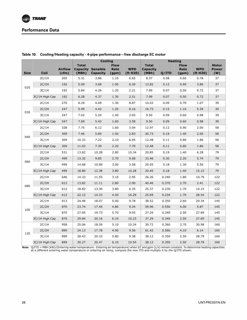
Table 10. Cooling/Heating capacity - 4-pipe performance—free discharge EC motor
Size CoilAirflow (cfm)
Cooling HeatingMotor Power (W)
Total Capacity(MBh)
Sensible Capacity
Flow Rate
(gpm)WPD
(ft H20)
TotalCapacity(MBh) Q/ITD
Flow Rate
(gpm)WPD
(ft H20)
020
2C/1H 205 5.31 3.86 1.10 6.65 8.37 0.08 0.60 0.78 37
2C/2H 192 5.09 3.68 1.00 6.20 13.82 0.13 0.90 3.86 37
3C/1H 192 5.84 4.26 1.20 2.21 7.99 0.07 0.50 0.72 37
3C/1H High Cap 192 6.28 4.37 1.30 2.51 7.99 0.07 0.50 0.72 37
030
2C/1H 270 6.29 4.69 1.30 8.87 10.03 0.09 0.70 1.07 39
2C/2H 247 5.99 4.42 1.20 8.16 16.73 0.15 1.10 5.39 39
3C/1H 247 7.02 5.20 1.40 3.05 9.50 0.09 0.60 0.98 39
3C/1H High Cap 247 7.69 5.43 1.60 3.58 9.50 0.09 0.60 0.98 39
040
2C/1H 328 7.75 6.12 1.60 3.04 12.97 0.12 0.90 2.00 58
2C/2H 309 7.46 5.85 1.50 2.83 20.73 0.19 1.40 2.00 58
3C/1H 309 10.33 7.22 2.10 6.94 12.48 0.11 0.80 1.86 58
3C/1H High Cap 309 11.03 7.39 2.20 7.79 12.48 0.11 0.80 1.86 58
060
2C/1H 531 13.82 10.28 2.80 10.34 20.85 0.19 1.40 6.28 79
2C/2H 499 13.32 9.85 2.70 9.68 33.46 0.30 2.20 5.74 79
3C/1H 499 14.68 10.89 3.00 3.58 20.05 0.18 1.30 5.56 79
3C/1H High Cap 499 18.80 12.38 3.80 10.28 20.45 0.18 1.40 15.15 79
080
2C/1H 646 14.33 11.55 3.10 2.95 26.26 0.240 1.80 10.79 122
2C/2H 612 13.82 11.11 2.80 2.90 40.46 0.370 2.70 2.41 122
3C/1H 612 18.82 13.30 3.80 6.35 25.37 0.230 1.70 10.15 122
3C/1H High Cap 612 22.12 14.33 4.50 16.29 25.69 0.234 1.70 28.54 122
100
2C/1H 913 24.48 18.07 5.00 9.78 38.52 0.350 2.60 29.34 145
2C/2H 870 23.74 17.45 4.80 9.24 59.96 0.550 4.00 5.87 145
3C/1H 870 27.95 19.73 5.70 9.05 37.29 0.340 2.50 27.69 145
3C/1H High Cap 870 29.84 20.16 6.10 10.23 37.29 0.340 2.50 27.69 145
120
2C/1H 958 25.06 18.59 5.10 10.24 39.72 0.360 2.70 30.98 160
2C/2H 899 24.13 17.78 4.90 9.56 61.42 0.560 4.10 6.14 160
3C/1H 899 28.43 20.10 5.80 9.38 38.12 0.350 2.50 28.79 160
3C/1H High Cap 899 30.27 20.47 6.10 10.54 38.12 0.350 2.50 28.79 160
Note: Q/ITD = MBh (kW)/(Entering water temperature - Entering air temperature) when ∆T and gpm (L/s) remain constant. To determine heating capacities at a different entering water temperature or entering air temp, compute the new ITD and multiply it by the Q/ITD shown.
28 UNT-PRC001N-EN
Performance Data
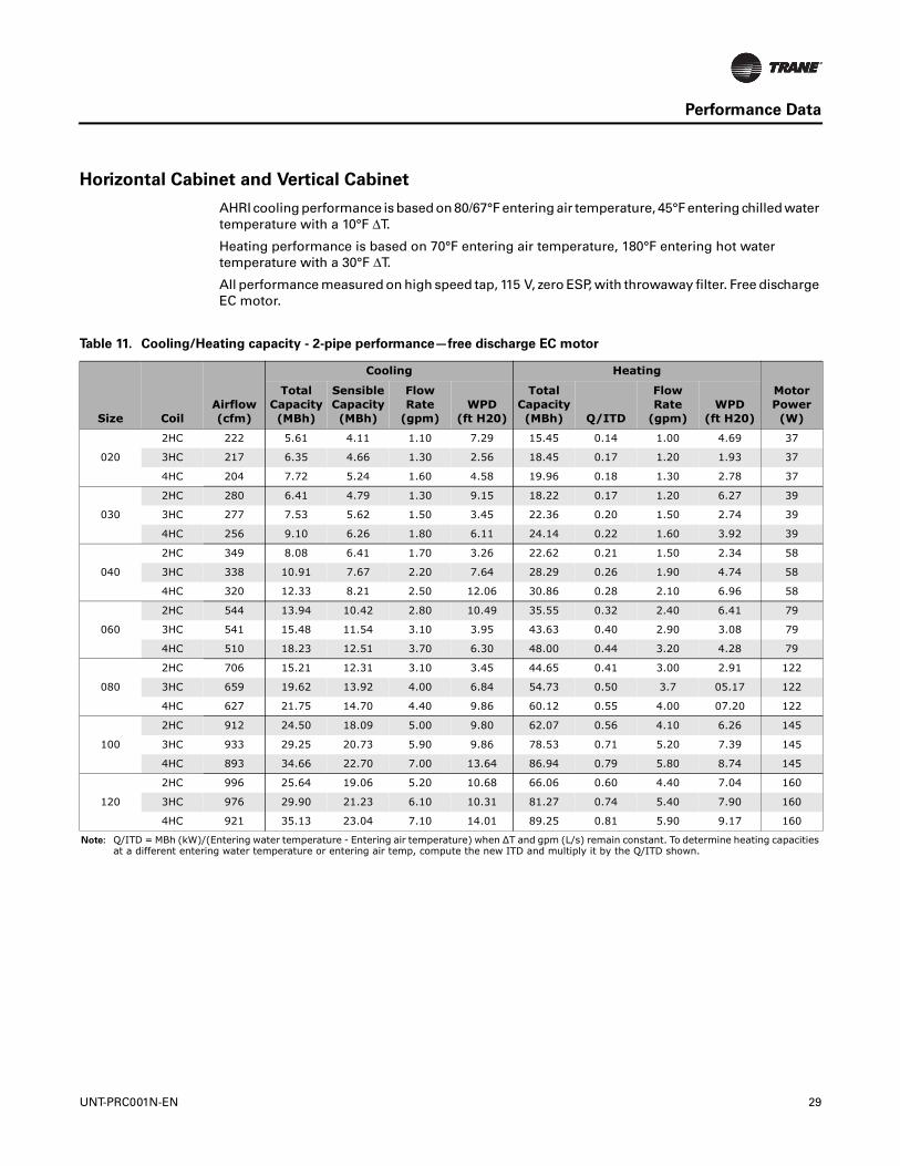
Horizontal Cabinet and Vertical Cabinet
AHRI cooling performance is based on 80/67°F entering air temperature, 45°F entering chilled water temperature with a 10°F ΔT.
Heating performance is based on 70°F entering air temperature, 180°F entering hot water temperature with a 30°F ΔT.
All performance measured on high speed tap, 115 V, zero ESP, with throwaway filter. Free discharge EC motor.
Table 11. Cooling/Heating capacity - 2-pipe performance—free discharge EC motor
Size CoilAirflow (cfm)
Cooling Heating
Motor Power (W)
Total Capacity(MBh)
Sensible Capacity (MBh)
Flow Rate
(gpm)WPD
(ft H20)
Total Capacity(MBh) Q/ITD
Flow Rate
(gpm)WPD
(ft H20)
020
2HC 222 5.61 4.11 1.10 7.29 15.45 0.14 1.00 4.69 37
3HC 217 6.35 4.66 1.30 2.56 18.45 0.17 1.20 1.93 37
4HC 204 7.72 5.24 1.60 4.58 19.96 0.18 1.30 2.78 37
030
2HC 280 6.41 4.79 1.30 9.15 18.22 0.17 1.20 6.27 39
3HC 277 7.53 5.62 1.50 3.45 22.36 0.20 1.50 2.74 39
4HC 256 9.10 6.26 1.80 6.11 24.14 0.22 1.60 3.92 39
040
2HC 349 8.08 6.41 1.70 3.26 22.62 0.21 1.50 2.34 58
3HC 338 10.91 7.67 2.20 7.64 28.29 0.26 1.90 4.74 58
4HC 320 12.33 8.21 2.50 12.06 30.86 0.28 2.10 6.96 58
060
2HC 544 13.94 10.42 2.80 10.49 35.55 0.32 2.40 6.41 79
3HC 541 15.48 11.54 3.10 3.95 43.63 0.40 2.90 3.08 79
4HC 510 18.23 12.51 3.70 6.30 48.00 0.44 3.20 4.28 79
080
2HC 706 15.21 12.31 3.10 3.45 44.65 0.41 3.00 2.91 122
3HC 659 19.62 13.92 4.00 6.84 54.73 0.50 3.7 05.17 122
4HC 627 21.75 14.70 4.40 9.86 60.12 0.55 4.00 07.20 122
100
2HC 912 24.50 18.09 5.00 9.80 62.07 0.56 4.10 6.26 145
3HC 933 29.25 20.73 5.90 9.86 78.53 0.71 5.20 7.39 145
4HC 893 34.66 22.70 7.00 13.64 86.94 0.79 5.80 8.74 145
120
2HC 996 25.64 19.06 5.20 10.68 66.06 0.60 4.40 7.04 160
3HC 976 29.90 21.23 6.10 10.31 81.27 0.74 5.40 7.90 160
4HC 921 35.13 23.04 7.10 14.01 89.25 0.81 5.90 9.17 160
Note: Q/ITD = MBh (kW)/(Entering water temperature - Entering air temperature) when ∆T and gpm (L/s) remain constant. To determine heating capacities at a different entering water temperature or entering air temp, compute the new ITD and multiply it by the Q/ITD shown.
UNT-PRC001N-EN 29

Performance Data
Table 12. Cooling/Heating capacity - 4-pipe performance—free discharge EC motor
Size CoilAirflow (cfm)
Cooling HeatingMotor Power (W)
Total Capacity(MBh)
Sensible Capacity (MBh)
Flow Rate (gpm)
WPD(ft H20)
Total Capacity(MBh) Q/ITD
Flow Rate (gpm)
WPD(ft H20)
020
2C/1H 217 5.49 4.00 1.10 7.02 8.70 0.08 0.60 0.88 37
2C/2H 204 5.28 3.83 1.10 6.58 14.50 0.13 1.00 4.20 37
3C/1H 204 6.09 4.45 1.20 2.37 8.35 0.08 0.60 0.78 37
3C/1H High Cap 204 6.54 4.56 1.30 2.69 8.35 0.08 0.60 0.78 37
030
2C/1H 277 6.38 4.76 1.30 9.08 10.20 0.09 0.70 1.11 39
2C/2H 256 6.09 4.52 1.20 8.40 17.13 0.16 1.10 5.62 39
3C/1H 256 7.16 5.31 1.50 3.16 9.70 0.09 0.70 1.01 39
3C/1H High Cap 256 7.84 5.54 1.60 3.70 9.70 0.09 0.70 1.01 39
040
2C/1H 338 7.89 6.24 1.60 3.13 13.22 0.12 0.90 2.06 58
2C/2H 320 7.61 5.99 1.60 2.94 21.26 0.19 1.40 2.09 58
3C/1H 320 10.53 7.38 2.10 7.19 12.76 0.12 0.90 1.94 58
3C/1H High Cap 320 11.24 7.55 2.30 8.06 12.76 0.12 0.90 1.94 58
060
2C/1H 541 13.86 10.35 2.80 10.39 21.08 0.19 1.40 6.08 79
2C/2H 510 13.48 9.99 2.70 9.90 34.00 0.31 2.30 6.91 79
3C/1H 510 14.89 11.06 3.00 3.68 20.34 0.19 1.40 5.70 79
3C/1H High Cap 510 19.03 12.55 3.90 10.50 20.71 0.19 1.40 15.54 79
080
2C/1H 659 14.50 11.69 3.00 3.16 26.60 0.24 1.80 11.04 122
2C/2H 627 14.02 11.29 2.90 2.98 41.17 0.37 2.70 2.50 122
3C/1H 627 19.06 13.49 3.90 6.50 25.78 0.23 1.70 10.44 122
3C/1H High Cap 627 22.37 14.50 4.50 16.61 26.09 0.24 1.70 29.39 122
100
2C/1H 933 24.77 18.32 5.00 9.99 39.07 0.36 2.60 30.09 145
2C/2H 893 24.08 17.74 4.90 9.49 61.10 0.56 4.10 6.08 145
3C/1H 893 28.38 20.06 5.80 9.31 37.94 0.35 2.50 28.55 145
3C/1H High Cap 893 30.27 20.48 6.10 10.51 37.94 0.35 2.50 28.55 145
120
2C/1H 976 25.30 18.77 5.20 10.42 40.19 0.37 2.70 31.65 160
2C/2H 921 24.45 18.05 5.00 9.80 62.51 0.57 4.20 6.35 160
3C/1H 921 28.83 20.40 5.90 9.63 38.73 0.35 2.6 29.63 160
3C/1H High Cap 921 30.67 20.76 6.20 10.81 38.73 0.35 2.6 29.63 160
Note: Q/ITD = MBh (kW)/(Entering water temperature - Entering air temperature) when ∆T and gpm (L/s) remain constant. To determine heating capacities at a different entering water temperature or entering air temp, compute the new ITD and multiply it by the Q/ITD shown.
30 UNT-PRC001N-EN
Performance Data
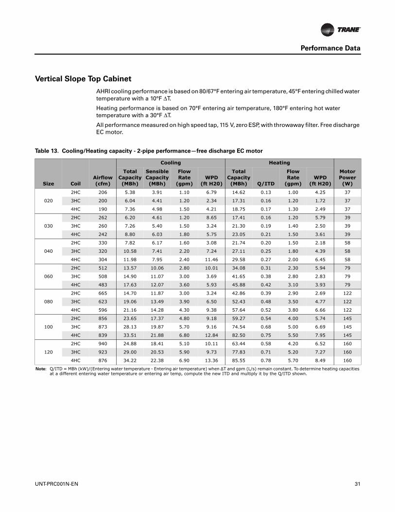
Vertical Slope Top Cabinet
AHRI cooling performance is based on 80/67°F entering air temperature, 45°F entering chilled water temperature with a 10°F ΔT.
Heating performance is based on 70°F entering air temperature, 180°F entering hot water temperature with a 30°F ΔT.
All performance measured on high speed tap, 115 V, zero ESP, with throwaway filter. Free discharge EC motor.
Table 13. Cooling/Heating capacity - 2-pipe performance—free discharge EC motor
Size CoilAirflow (cfm)
Cooling Heating
Motor Power (W)
Total Capacity(MBh)
Sensible Capacity (MBh)
Flow Rate
(gpm)WPD
(ft H20)
Total Capacity(MBh) Q/ITD
Flow Rate
(gpm)WPD
(ft H20)
020
2HC 206 5.38 3.91 1.10 6.79 14.62 0.13 1.00 4.25 37
3HC 200 6.04 4.41 1.20 2.34 17.31 0.16 1.20 1.72 37
4HC 190 7.36 4.98 1.50 4.21 18.75 0.17 1.30 2.49 37
030
2HC 262 6.20 4.61 1.20 8.65 17.41 0.16 1.20 5.79 39
3HC 260 7.26 5.40 1.50 3.24 21.30 0.19 1.40 2.50 39
4HC 242 8.80 6.03 1.80 5.75 23.05 0.21 1.50 3.61 39
040
2HC 330 7.82 6.17 1.60 3.08 21.74 0.20 1.50 2.18 58
3HC 320 10.58 7.41 2.20 7.24 27.11 0.25 1.80 4.39 58
4HC 304 11.98 7.95 2.40 11.46 29.58 0.27 2.00 6.45 58
060
2HC 512 13.57 10.06 2.80 10.01 34.08 0.31 2.30 5.94 79
3HC 508 14.90 11.07 3.00 3.69 41.65 0.38 2.80 2.83 79
4HC 483 17.63 12.07 3.60 5.93 45.88 0.42 3.10 3.93 79
080
2HC 665 14.70 11.87 3.00 3.24 42.86 0.39 2.90 2.69 122
3HC 623 19.06 13.49 3.90 6.50 52.43 0.48 3.50 4.77 122
4HC 596 21.16 14.28 4.30 9.38 57.64 0.52 3.80 6.66 122
100
2HC 856 23.65 17.37 4.80 9.18 59.27 0.54 4.00 5.74 145
3HC 873 28.13 19.87 5.70 9.16 74.54 0.68 5.00 6.69 145
4HC 839 33.51 21.88 6.80 12.84 82.50 0.75 5.50 7.95 145
120
2HC 940 24.88 18.41 5.10 10.11 63.44 0.58 4.20 6.52 160
3HC 923 29.00 20.53 5.90 9.73 77.83 0.71 5.20 7.27 160
4HC 876 34.22 22.38 6.90 13.36 85.55 0.78 5.70 8.49 160
Note: Q/ITD = MBh (kW)/(Entering water temperature - Entering air temperature) when ∆T and gpm (L/s) remain constant. To determine heating capacities at a different entering water temperature or entering air temp, compute the new ITD and multiply it by the Q/ITD shown.
UNT-PRC001N-EN 31
Performance Data
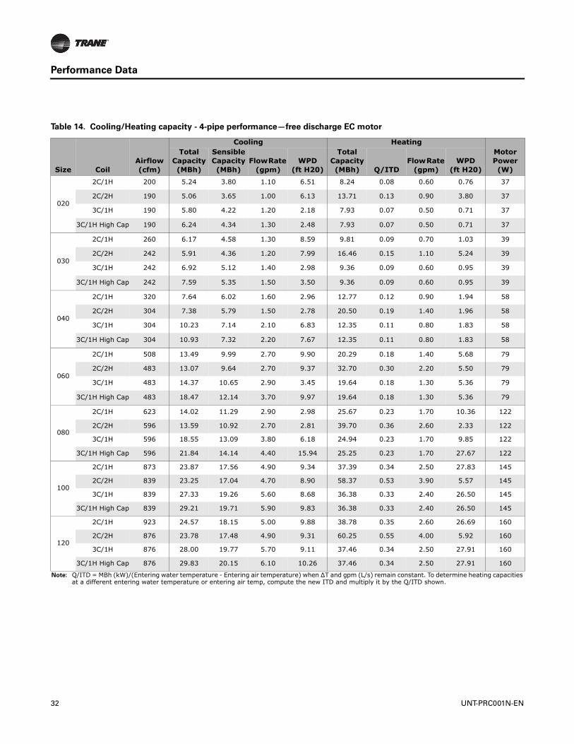
Table 14. Cooling/Heating capacity - 4-pipe performance—free discharge EC motor
Size CoilAirflow (cfm)
Cooling HeatingMotor Power (W)
Total Capacity(MBh)
Sensible Capacity (MBh)
Flow Rate (gpm)
WPD(ft H20)
Total Capacity(MBh) Q/ITD
Flow Rate (gpm)
WPD(ft H20)
020
2C/1H 200 5.24 3.80 1.10 6.51 8.24 0.08 0.60 0.76 37
2C/2H 190 5.06 3.65 1.00 6.13 13.71 0.13 0.90 3.80 37
3C/1H 190 5.80 4.22 1.20 2.18 7.93 0.07 0.50 0.71 37
3C/1H High Cap 190 6.24 4.34 1.30 2.48 7.93 0.07 0.50 0.71 37
030
2C/1H 260 6.17 4.58 1.30 8.59 9.81 0.09 0.70 1.03 39
2C/2H 242 5.91 4.36 1.20 7.99 16.46 0.15 1.10 5.24 39
3C/1H 242 6.92 5.12 1.40 2.98 9.36 0.09 0.60 0.95 39
3C/1H High Cap 242 7.59 5.35 1.50 3.50 9.36 0.09 0.60 0.95 39
040
2C/1H 320 7.64 6.02 1.60 2.96 12.77 0.12 0.90 1.94 58
2C/2H 304 7.38 5.79 1.50 2.78 20.50 0.19 1.40 1.96 58
3C/1H 304 10.23 7.14 2.10 6.83 12.35 0.11 0.80 1.83 58
3C/1H High Cap 304 10.93 7.32 2.20 7.67 12.35 0.11 0.80 1.83 58
060
2C/1H 508 13.49 9.99 2.70 9.90 20.29 0.18 1.40 5.68 79
2C/2H 483 13.07 9.64 2.70 9.37 32.70 0.30 2.20 5.50 79
3C/1H 483 14.37 10.65 2.90 3.45 19.64 0.18 1.30 5.36 79
3C/1H High Cap 483 18.47 12.14 3.70 9.97 19.64 0.18 1.30 5.36 79
080
2C/1H 623 14.02 11.29 2.90 2.98 25.67 0.23 1.70 10.36 122
2C/2H 596 13.59 10.92 2.70 2.81 39.70 0.36 2.60 2.33 122
3C/1H 596 18.55 13.09 3.80 6.18 24.94 0.23 1.70 9.85 122
3C/1H High Cap 596 21.84 14.14 4.40 15.94 25.25 0.23 1.70 27.67 122
100
2C/1H 873 23.87 17.56 4.90 9.34 37.39 0.34 2.50 27.83 145
2C/2H 839 23.25 17.04 4.70 8.90 58.37 0.53 3.90 5.57 145
3C/1H 839 27.33 19.26 5.60 8.68 36.38 0.33 2.40 26.50 145
3C/1H High Cap 839 29.21 19.71 5.90 9.83 36.38 0.33 2.40 26.50 145
120
2C/1H 923 24.57 18.15 5.00 9.88 38.78 0.35 2.60 26.69 160
2C/2H 876 23.78 17.48 4.90 9.31 60.25 0.55 4.00 5.92 160
3C/1H 876 28.00 19.77 5.70 9.11 37.46 0.34 2.50 27.91 160
3C/1H High Cap 876 29.83 20.15 6.10 10.26 37.46 0.34 2.50 27.91 160
Note: Q/ITD = MBh (kW)/(Entering water temperature - Entering air temperature) when ∆T and gpm (L/s) remain constant. To determine heating capacities at a different entering water temperature or entering air temp, compute the new ITD and multiply it by the Q/ITD shown.
32 UNT-PRC001N-EN
Performance Data
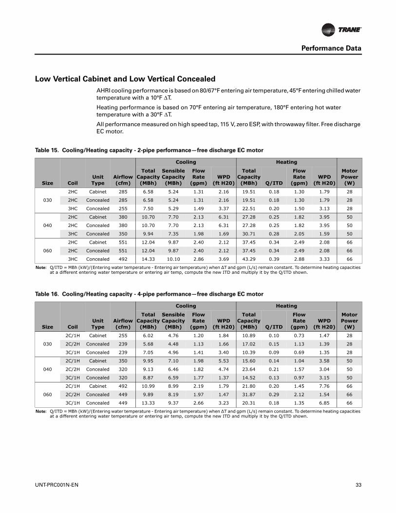
Low Vertical Cabinet and Low Vertical Concealed
AHRI cooling performance is based on 80/67°F entering air temperature, 45°F entering chilled water temperature with a 10°F ΔT.
Heating performance is based on 70°F entering air temperature, 180°F entering hot water temperature with a 30°F ΔT.
All performance measured on high speed tap, 115 V, zero ESP, with throwaway filter. Free discharge EC motor.
Table 15. Cooling/Heating capacity - 2-pipe performance—free discharge EC motor
Size CoilUnit Type
Airflow (cfm)
Cooling Heating
Motor Power (W)
Total Capacity(MBh)
Sensible Capacity (MBh)
Flow Rate
(gpm)WPD
(ft H20)
Total Capacity(MBh) Q/ITD
Flow Rate
(gpm)WPD
(ft H20)
030
2HC Cabinet 285 6.58 5.24 1.31 2.16 19.51 0.18 1.30 1.79 28
2HC Concealed 285 6.58 5.24 1.31 2.16 19.51 0.18 1.30 1.79 28
3HC Concealed 255 7.50 5.29 1.49 3.37 22.51 0.20 1.50 3.13 28
040
2HC Cabinet 380 10.70 7.70 2.13 6.31 27.28 0.25 1.82 3.95 50
2HC Concealed 380 10.70 7.70 2.13 6.31 27.28 0.25 1.82 3.95 50
3HC Concealed 350 9.94 7.35 1.98 1.69 30.71 0.28 2.05 1.59 50
060
2HC Cabinet 551 12.04 9.87 2.40 2.12 37.45 0.34 2.49 2.08 66
2HC Concealed 551 12.04 9.87 2.40 2.12 37.45 0.34 2.49 2.08 66
3HC Concealed 492 14.33 10.10 2.86 3.69 43.29 0.39 2.88 3.33 66
Note: Q/ITD = MBh (kW)/(Entering water temperature - Entering air temperature) when ∆T and gpm (L/s) remain constant. To determine heating capacities at a different entering water temperature or entering air temp, compute the new ITD and multiply it by the Q/ITD shown.
Table 16. Cooling/Heating capacity - 4-pipe performance—free discharge EC motor
Size CoilUnit Type
Airflow (cfm)
Cooling Heating
Motor Power (W)
Total Capacity(MBh)
Sensible Capacity (MBh)
Flow Rate
(gpm)WPD
(ft H20)
Total Capacity(MBh) Q/ITD
Flow Rate
(gpm)WPD
(ft H20)
030
2C/1H Cabinet 255 6.02 4.76 1.20 1.84 10.89 0.10 0.73 1.47 28
2C/2H Concealed 239 5.68 4.48 1.13 1.66 17.02 0.15 1.13 1.39 28
3C/1H Concealed 239 7.05 4.96 1.41 3.40 10.39 0.09 0.69 1.35 28
040
2C/1H Cabinet 350 9.95 7.10 1.98 5.53 15.60 0.14 1.04 3.58 50
2C/2H Concealed 320 9.13 6.46 1.82 4.74 23.64 0.21 1.57 3.04 50
3C/1H Concealed 320 8.87 6.59 1.77 1.37 14.52 0.13 0.97 3.15 50
060
2C/1H Cabinet 492 10.99 8.99 2.19 1.79 21.80 0.20 1.45 7.76 66
2C/2H Concealed 449 9.89 8.19 1.97 1.47 31.87 0.29 2.12 1.54 66
3C/1H Concealed 449 13.33 9.37 2.66 3.23 20.31 0.18 1.35 6.85 66
Note: Q/ITD = MBh (kW)/(Entering water temperature - Entering air temperature) when ∆T and gpm (L/s) remain constant. To determine heating capacities at a different entering water temperature or entering air temp, compute the new ITD and multiply it by the Q/ITD shown.
UNT-PRC001N-EN 33

Performance Data
Horizontal Concealed, Compact Concealed, Horizontal Cabinet, Horizontal Recessed and
Vertical Recessed
AHRI cooling performance is based on 80/67°F entering air temperature, 45°F entering chilled water temperature with a 10°F ΔT.
Heating performance is based on 70°F entering air temperature, 180°F entering hot water temperature with a 30°F ΔT.
All performance measured on high speed tap, 115 V, 0.20 ESP, without filter. High static EC motor.
Table 17. Cooling/Heating capacity - 2-pipe performance—high static EC motor
Size CoilAirflow (cfm)
Cooling Heating
Motor Power (W)
Total Capacity(MBh)
Sensible Capacity (MBh)
Flow Rate
(gpm)WPD
(ft H20)
Total Capacity(MBh) Q/ITD
Flow Rate
(gpm)WPD
(ft H20)
020
2HC 314 6.92 5.25 1.40 10.83 19.68 0.18 1.30 7.18 84
3HC 319 8.40 6.35 1.70 4.32 24.71 0.23 1.70 3.28 84
4HC 295 10.27 7.14 2.10 7.75 27.07 0.25 1.80 4.83 84
030
2HC 380 7.63 5.91 1.60 12.84 22.14 0.20 1.50 8.85 91
3HC 358 9.00 6.88 1.90 4.89 26.79 0.24 1.80 3.80 91
4HC 330 11.05 7.75 2.30 8.83 29.53 0.27 2.00 5.65 91
040
2HC 410 9.09 7.33 1.90 4.16 25.18 0.23 1.70 2.85 110
3HC 506 14.30 10.45 2.90 12.60 37.81 0.34 2.50 8.05 110
4HC 470 16.38 11.23 3.30 20.25 41.90 0.38 2.80 12.12 110
060
2HC 700 16.22 12.50 3.30 14.16 41.80 0.38 2.80 8.63 162
3HC 824 20.72 16.04 4.20 6.91 58.43 0.53 3.90 5.36 162
4HC 760 24.46 17.32 5.00 10.99 65.21 0.59 4.30 7.59 162
080
2HC 950 18.83 15.64 4.00 5.40 53.86 0.49 3.60 4.16 298
3HC 927 25.08 18.35 5.20 11.17 69.93 0.64 4.70 8.20 298
4HC 870 27.85 19.29 5.80 16.00 77.84 0.71 5.20 11.67 298
100
2HC 1199 29.39 22.38 6.00 13.98 74.76 0.68 5.00 8.90 252
3HC 1360 38.20 27.95 7.80 16.58 103.27 0.94 6.90 12.55 252
4HC 1276 45.19 30.40 9.20 22.30 115.47 1.05 7.70 14.73 252
120
2HC 1330 30.90 23.78 6.40 15.50 79.76 0.73 5.30 10.07 314
3HC 1419 39.09 28.71 8.00 17.49 106.28 0.97 7.10 13.27 314
4HC 1330 46.31 31.24 9.40 23.50 119.18 1.08 7.90 15.62 314
Note: Q/ITD = MBh (kW)/(Entering water temperature - Entering air temperature) when ∆T and gpm (L/s) remain constant. To determine heating capacities at a different entering water temperature or entering air temp, compute the new ITD and multiply it by the Q/ITD shown.
34 UNT-PRC001N-EN
Performance Data
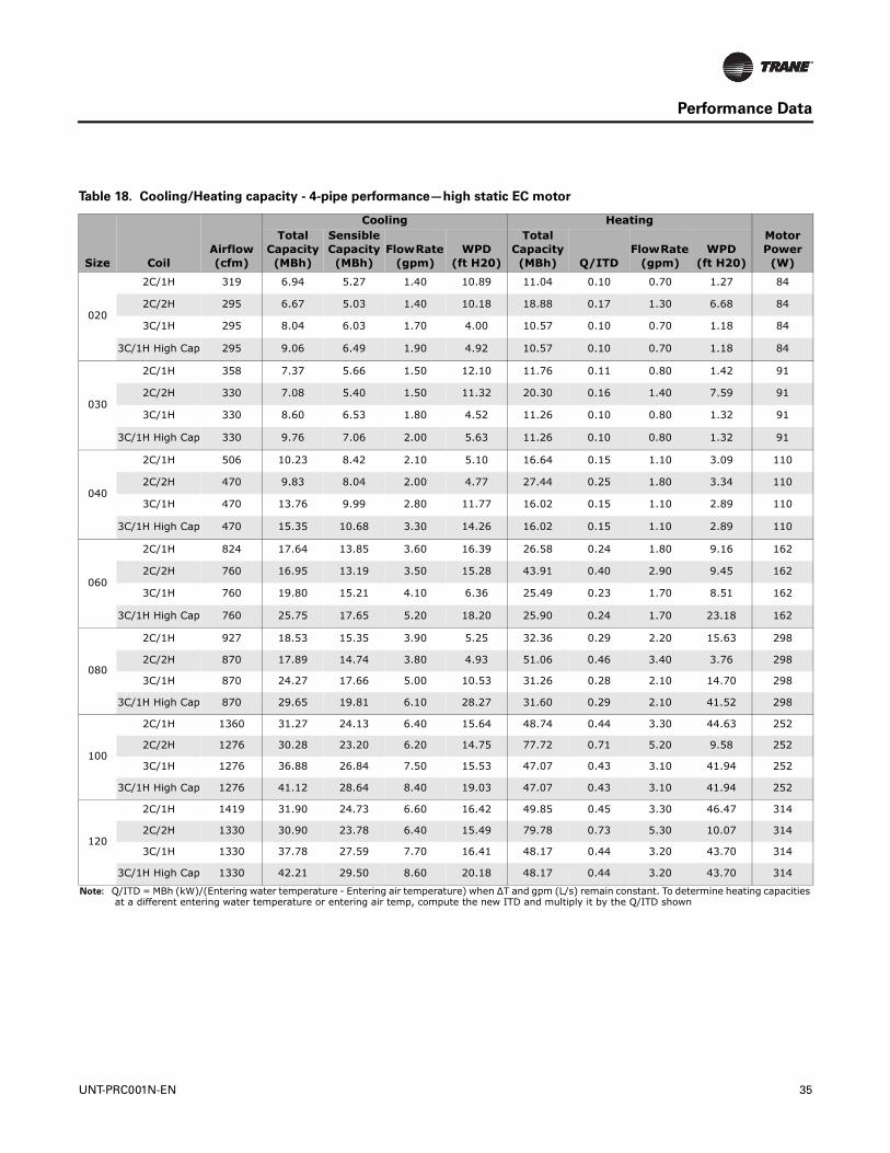
Table 18. Cooling/Heating capacity - 4-pipe performance—high static EC motor
Size CoilAirflow (cfm)
Cooling HeatingMotor Power (W)
Total Capacity(MBh)
Sensible Capacity (MBh)
Flow Rate (gpm)
WPD(ft H20)
Total Capacity(MBh) Q/ITD
Flow Rate (gpm)
WPD(ft H20)
020
2C/1H 319 6.94 5.27 1.40 10.89 11.04 0.10 0.70 1.27 84
2C/2H 295 6.67 5.03 1.40 10.18 18.88 0.17 1.30 6.68 84
3C/1H 295 8.04 6.03 1.70 4.00 10.57 0.10 0.70 1.18 84
3C/1H High Cap 295 9.06 6.49 1.90 4.92 10.57 0.10 0.70 1.18 84
030
2C/1H 358 7.37 5.66 1.50 12.10 11.76 0.11 0.80 1.42 91
2C/2H 330 7.08 5.40 1.50 11.32 20.30 0.16 1.40 7.59 91
3C/1H 330 8.60 6.53 1.80 4.52 11.26 0.10 0.80 1.32 91
3C/1H High Cap 330 9.76 7.06 2.00 5.63 11.26 0.10 0.80 1.32 91
040
2C/1H 506 10.23 8.42 2.10 5.10 16.64 0.15 1.10 3.09 110
2C/2H 470 9.83 8.04 2.00 4.77 27.44 0.25 1.80 3.34 110
3C/1H 470 13.76 9.99 2.80 11.77 16.02 0.15 1.10 2.89 110
3C/1H High Cap 470 15.35 10.68 3.30 14.26 16.02 0.15 1.10 2.89 110
060
2C/1H 824 17.64 13.85 3.60 16.39 26.58 0.24 1.80 9.16 162
2C/2H 760 16.95 13.19 3.50 15.28 43.91 0.40 2.90 9.45 162
3C/1H 760 19.80 15.21 4.10 6.36 25.49 0.23 1.70 8.51 162
3C/1H High Cap 760 25.75 17.65 5.20 18.20 25.90 0.24 1.70 23.18 162
080
2C/1H 927 18.53 15.35 3.90 5.25 32.36 0.29 2.20 15.63 298
2C/2H 870 17.89 14.74 3.80 4.93 51.06 0.46 3.40 3.76 298
3C/1H 870 24.27 17.66 5.00 10.53 31.26 0.28 2.10 14.70 298
3C/1H High Cap 870 29.65 19.81 6.10 28.27 31.60 0.29 2.10 41.52 298
100
2C/1H 1360 31.27 24.13 6.40 15.64 48.74 0.44 3.30 44.63 252
2C/2H 1276 30.28 23.20 6.20 14.75 77.72 0.71 5.20 9.58 252
3C/1H 1276 36.88 26.84 7.50 15.53 47.07 0.43 3.10 41.94 252
3C/1H High Cap 1276 41.12 28.64 8.40 19.03 47.07 0.43 3.10 41.94 252
120
2C/1H 1419 31.90 24.73 6.60 16.42 49.85 0.45 3.30 46.47 314
2C/2H 1330 30.90 23.78 6.40 15.49 79.78 0.73 5.30 10.07 314
3C/1H 1330 37.78 27.59 7.70 16.41 48.17 0.44 3.20 43.70 314
3C/1H High Cap 1330 42.21 29.50 8.60 20.18 48.17 0.44 3.20 43.70 314
Note: Q/ITD = MBh (kW)/(Entering water temperature - Entering air temperature) when ∆T and gpm (L/s) remain constant. To determine heating capacities at a different entering water temperature or entering air temp, compute the new ITD and multiply it by the Q/ITD shown
UNT-PRC001N-EN 35

Performance Data
Vertical Concealed
AHRI cooling performance is based on 80/67°F entering air temperature, 45°F entering chilled water temperature with a 10°F ΔT.
Heating performance is based on 70°F entering air temperature, 180°F entering hot water temperature with a 30°F ΔT.
All performance measured on high speed tap, 115 V, 0.20 ESP, without filter. High static EC motor.
Table 19. Cooling/Heating capacity - 2-pipe performance—high static EC motor
Size CoilAirflow (cfm)
Cooling Heating
Motor Power (W)
Total Capacity(MBh)
Sensible Capacity (MBh)
Flow Rate
(gpm)WPD
(ft H20)
Total Capacity(MBh) Q/ITD
Flow Rate
(gpm)WPD
(ft H20)
020
2HC 274 6.45 4.83 1.30 9.63 17.95 0.16 1.20 6.11 84
3HC 274 7.71 5.76 1.60 3.72 22.13 0.20 1.50 2.68 84
4HC 258 9.45 6.51 1.90 6.71 24.31 0.22 1.60 3.97 84
030
2HC 341 7.26 5.56 1.50 11.80 20.70 0.19 1.40 7.86 91
3HC 319 8.47 6.41 1.80 4.40 24.76 0.23 1.70 3.29 91
4HC 299 10.43 7.27 2.10 8.00 27.36 0.25 1.80 4.92 91
040
2HC 377 8.67 6.94 1.80 3.83 23.84 0.22 1.60 2.58 110
3HC 455 13.57 9.83 2.80 11.49 35.17 0.32 2.30 7.05 110
4HC 429 15.58 10.61 3.20 18.55 39.04 0.36 2.60 10.66 110
060
2HC 632 15.42 11.76 3.20 12.96 39.23 0.36 2.60 7.68 162
3HC 733 19.49 14.93 4.00 6.18 54.10 0.49 3.60 4.63 162
4HC 687 23.15 16.27 4.70 9.95 60.53 0.55 4.00 6.60 162
080
2HC 865 17.96 14.80 3.80 4.96 50.88 0.46 3.40 3.73 298
3HC 845 24.00 17.44 5.00 10.33 65.58 0.60 4.40 7.26 298
4HC 800 26.69 18.39 5.50 14.85 73.06 0.66 4.90 10.36 298
100
2HC 1089 27.95 21.08 5.70 12.76 70.18 0.64 4.70 7.90 252
3HC 1206 35.92 26.04 7.30 14.78 95.02 0.86 6.30 10.68 252
4HC 1145 42.77 28.58 8.70 20.20 106.34 0.97 7.10 12.65 252
120
2HC 1218 29.62 22.60 6.10 14.36 75.51 0.69 5.00 9.07 314
3HC 1291 37.31 27.20 7.70 16.04 99.64 0.91 6.60 11.71 314
4HC 1223 44.42 29.81 9.10 21.81 111.87 1.02 7.50 13.89 314
Note: Q/ITD = MBh (kW)/(Entering water temperature - Entering air temperature) when ∆T and gpm (L/s) remain constant. To determine heating capacities at a different entering water temperature or entering air temp, compute the new ITD and multiply it by the Q/ITD shown.
36 UNT-PRC001N-EN

Performance Data
Table 20. Cooling/Heating capacity - 4-pipe performance—high static EC motor
Size CoilAirflow (cfm)
Cooling HeatingMotor Power (W)
Total Capacity(MBh)
Sensible Capacity (MBh)
Flow Rate
(gpm)WPD
(ft H20)
Total Capacity(MBh) Q/ITD
Flow Rate
(gpm)WPD
(ft H20)
020
2C/1H 274 6.43 4.82 1.30 9.58 10.11 0.09 0.70 1.09 84
2C/2H 258 6.21 4.63 1.30 9.05 17.23 0.16 1.20 5.69 84
3C/1H 258 7.42 5.51 1.50 3.48 9.76 0.09 0.70 1.02 84
3C/1H High Cap 258 8.37 5.94 1.70 4.29 9.76 0.09 0.70 1.02 84
030
2C/1H 319 6.99 5.31 1.50 11.07 11.06 0.10 0.70 1.27 91
2C/2H 299 6.75 5.10 1.40 10.44 19.05 0.17 1.30 6.78 91
3C/1H 299 8.16 6.13 1.70 4.13 10.66 0.10 0.70 1.19 91
3C/1H High Cap 299 9.25 6.64 1.90 5.12 10.66 0.10 0.70 1.19 91
040
2C/1H 455 9.69 7.90 2.00 4.64 15.73 0.14 1.10 2.80 110
2C/2H 429 9.36 7.59 1.90 4.38 25.90 0.24 1.70 3.01 110
3C/1H 429 13.11 9.45 2.70 10.83 15.22 0.14 1.00 2.64 110
3C/1H High Cap 429 14.64 10.11 3.00 13.11 15.22 0.14 1.00 2.64 110
060
2C/1H 733 16.70 12.95 3.40 14.89 25.02 0.23 1.70 8.23 162
2C/2H 687 16.14 12.42 3.30 14.03 41.30 0.38 2.80 8.45 162
3C/1H 687 1874.00 14.27 3.90 5.76 24.16 0.22 1.60 7.74 162
3C/1H High Cap 687 24.46 16.64 5.00 16.63 24.57 0.22 1.60 21.07 162
080
2C/1H 845 17.67 14.53 3.70 4.83 30.77 0.28 2.10 14.29 298
2C/2H 800 17.11 14.00 3.60 4.56 48.47 0.44 3.20 3.40 298
3C/1H 800 23.29 16.85 4.80 9.73 29.85 0.27 2.00 13.54 298
3C/1H High Cap 800 28.53 18.96 5.90 26.43 30.18 0.27 2.00 38.20 298
100
2C/1H 1206 29.52 22.51 6.10 14.09 45.62 0.42 3.00 39.67 252
2C/2H 1145 28.69 21.75 5.90 13.38 72.56 0.66 4.80 8.41 252
3C/1H 1145 34.83 25.14 7.10 13.95 44.29 0.40 3.00 37.62 252
3C/1H High Cap 1145 38.86 26.88 7.90 17.12 44.29 0.40 3.00 37.62 252
120
2C/1H 1291 30.53 23.43 6.30 15.16 47.38 0.43 3.20 42.44 314
2C/2H 1223 29.67 22.65 6.10 14.40 75.70 0.69 5.00 9.12 314
3C/1H 1223 36.18 26.25 7.40 15.14 45.98 0.42 3.10 40.23 314
3C/1H High Cap 1223 40.45 28.11 8.30 18.64 45.98 0.42 3.10 40.23 314
Note: Q/ITD = MBh (kW)/(Entering water temperature - Entering air temperature) when ∆T and gpm (L/s) remain constant. To determine heating capacities at a different entering water temperature or entering air temp, compute the new ITD and multiply it by the Q/ITD shown.
UNT-PRC001N-EN 37

Performance Data
Standard Capacity and High Capacity for Hot Water and Steam Reheat
Coils
Horizontal Concealed, Compact Concealed, Horizontal Recessed and Vertical Recessed
The following performance data represents the 1-row hot water and steam reheat coils that are available on fan coil units in conjunction with a 2, 3, or 4-row cooling coil.
Heating performance is based on 55°F entering air temperature, 180°F entering hot water temperature (hot water coil) or 2 psig and 5 psig entering steam pressure (steam coil) and a 15°F ΔT.
All performance measured on high speed tap, 115 V, 0.05 ESP, without filter. Free discharge EC motor.
Table 21. Standard capacity and high capacity hot water reheat coil—free discharge EC motor
Size
Main Cooling
CoilAirflow (cfm)
Standard capacity hot water reheat coil High capacity hot water reheat coil
Motor Power (W)
Total Capacity(MBh) Q/ITD
Flow Rate
(gpm)WPD
(ft H20)
Total Capacity(MBh) Q/ITD
Flow Rate
(gpm)WPD
(ft H20)
020
2-row 246 3.96 0.03 0.50 0.07 8.67 0.07 1.20 0.28 37
3-row 242 3.89 0.03 0.50 0.07 8.55 0.07 1.10 0.27 37
4-row 222 3.73 0.03 0.50 0.06 8.27 0.07 1.10 0.26 37
030
2-row 313 4.45 0.04 0.60 0.09 9.49 0.08 1.30 0.33 39
3-row 309 4.42 0.04 0.60 0.09 9.43 0.08 1.30 0.33 39
4-row 276 4.18 0.03 0.60 0.08 9.04 0.07 1.20 0.30 39
040
2-row 381 5.95 0.05 0.80 0.17 12.81 0.10 1.70 0.66 58
3-row 365 5.69 0.05 0.80 0.16 12.37 0.10 1.70 0.62 58
4-row 340 5.46 0.04 0.70 0.15 11.98 0.10 1.60 0.59 58
060
2-row 609 9.51 0.08 1.30 0.51 20.34 0.16 2.70 1.93 79
3-row 604 9.34 0.08 1.20 0.49 20.05 0.16 2.70 1.88 79
4-row 557 8.83 0.07 1.20 0.44 19.19 0.15 2.60 1.74 79
080
2-row 790 12.02 0.10 1.60 0.92 25.94 0.21 3.50 3.58 122
3-row 724 11.22 0.09 1.50 0.81 24.60 0.20 3.30 3.26 122
4-row 676 10.92 0.09 1.50 0.78 24.08 0.19 3.20 3.14 122
100
2-row 1015 17.34 0.14 2.30 2.41 38.00 0.30 5.10 9.73 145
3-row 1052 17.22 0.14 2.30 2.38 37.80 0.30 5.00 9.64 145
4-row 1105 16.37 0.13 2.40 2.18 36.33 0.29 4.80 8.98 160
120
2-row 988 17.97 0.14 2.40 2.57 39.07 0.31 5.20 10.22 145
3-row 1074 17.33 0.14 2.30 2.41 37.99 0.30 5.10 9.72 160
4-row 993 16.36 0.13 2.20 2.18 36.33 0.29 4.80 8.97 160
Note: Q/ITD = MBh (kW)/(Entering water temperature - Entering air temperature) when ∆T and gpm (L/s) remain constant. To determine heating capacities at a different entering water temperature or entering air temp, compute the new ITD and multiply it by the Q/ITD shown.
38 UNT-PRC001N-EN

Performance Data
Table 22. Steam coil performance—free discharge EC motor
Size
Main Cooling
CoilAirflow (cfm)
2 PSIG 5 PSIG
Motor Power (W)
Total Capacity(MBh) Q/ITD
Heating LAT (F)
Total Capacity(MBh) Q/ITD
Heating LAT (F)
020
2-row 246 7.65 0.05 86.73 8.06 0.05 88.41 37
3-row 242 7.53 0.05 87.14 7.93 0.05 88.84 37
4-row 222 7.22 0.05 88.21 7.60 0.05 89.96 37
030
2-row 313 8.57 0.06 84.02 9.02 0.06 85.55 39
3-row 309 8.50 0.06 84.21 8.95 0.06 85.75 39
4-row 276 8.06 0.05 85.45 8.49 0.05 87.06 39
040
2-row 381 11.07 0.07 84.74 11.66 0.07 86.31 58
3-row 365 10.61 0.07 85.77 11.17 0.07 87.39 58
4-row 340 10.19 0.07 88.76 10.73 0.07 88.44 58
060
2-row 609 17.09 0.12 83.66 18.00 0.12 85.18 79
3-row 604 16.79 0.11 84.07 17.68 0.11 85.61 79
4-row 557 15.92 0.11 85.34 16.76 0.11 86.95 79
080
2-row 790 21.28 0.14 84.43 22.41 0.14 85.99 122
3-row 724 19.93 0.13 86.00 20.99 0.13 87.64 122
4-row 676 19.42 0.13 86.64 20.45 0.13 88.32 122
100
2-row 1015 30.15 0.20 85.69 31.77 0.20 87.33 145
3-row 1052 29.97 0.20 85.84 31.57 0.20 87.49 145
4-row 988 28.56 0.19 87.04 30.09 0.19 88.75 145
120
2-row 1105 31.19 0.21 84.86 32.86 0.21 86.46 160
3-row 1074 30.14 0.20 85.69 31.76 0.20 87.34 160
4-row 993 28.55 0.19 87.05 30.08 0.19 88.76 160
Note: Q/ITD = MBh (kW)/(Entering water temperature - Entering air temperature) when ∆T and gpm (L/s) remain constant. To determine heating capacities at a different entering water temperature or entering air temp, compute the new ITD and multiply it by the Q/ITD shown.
UNT-PRC001N-EN 39

Performance Data
Vertical Concealed
The following performance data represents the 1-row hot water and steam reheat coils that are available on fan coil units in conjunction with a 2, 3, or 4-row cooling coil.
Heating performance is based on 55°F entering air temperature, 180°F entering hot water temperature (hot water coil) or 2 psig and 5 psig entering steam pressure (steam coil) and a 15°F ΔT.
All performance measured on high speed tap, 115 V, 0.05 ESP, without filter. Free discharge EC motor.
Table 23. Standard capacity and high capacity hot water reheat coil—free discharge EC motor
Size
Main Cooling
CoilAirflow (cfm)
Standard capacity hot water reheat coil High capacity hot water reheat coil
Motor Power (W)
Total Capacity(MBh) Q/ITD
Flow Rate
(gpm)WPD
(ft H20)
Total Capacity(MBh) Q/ITD
Flow Rate
(gpm)WPD
(ft H20)
020
2-row 211 3.69 0.03 0.50 0.06 8.20 0.07 1.10 0.25 37
3-row 205 3.61 0.03 0.50 0.06 8.07 0.07 1.10 0.25 37
4-row 192 3.48 0.03 0.50 0.06 7.85 0.06 1.10 0.24 37
030
2-row 272 4.20 0.03 0.60 0.08 9.06 0.07 1.20 0.30 39
3-row 270 4.17 0.03 0.60 0.08 9.02 0.07 1.20 0.30 39
4-row 247 3.98 0.03 0.50 0.07 8.71 0.07 1.20 0.28 39
040
2-row 340 5.65 0.05 0.80 0.16 12.30 0.10 1.60 0.61 58
3-row 328 5.44 0.04 0.70 0.15 11.94 0.10 1.60 0.58 58
4-row 309 5.24 0.04 0.70 0.14 11.61 0.09 1.60 0.55 58
060
2-row 535 8.96 0.07 1.20 0.46 19.41 0.16 2.60 1.78 79
3-row 531 8.82 0.07 1.20 0.44 19.18 0.15 2.60 1.74 79
4-row 499 8.43 0.07 1.10 0.41 18.51 0.15 2.50 1.64 79
080
2-row 697 11.43 0.09 1.50 0.84 24.95 0.20 3.30 3.34 122
3-row 646 10.76 0.09 1.40 0.76 23.80 0.19 3.20 3.07 122
4-row 612 10.51 0.08 1.40 0.72 23.37 0.19 3.10 2.97 122
100
2-row 891 16.33 0.13 2.20 2.17 36.27 0.29 4.80 8.95 145
3-row 913 16.25 0.13 2.20 2.15 36.13 0.29 4.80 8.89 145
4-row 870 15.57 0.13 2.10 1.99 34.95 0.28 4.70 8.38 145
120
2-row 980 17.06 0.14 2.30 2.34 37.52 0.30 5.00 9.51 160
3-row 958 16.56 0.13 2.20 2.22 36.66 0.29 4.90 9.12 160
4-row 899 15.75 0.13 2.10 2.04 35.26 0.28 4.70 8.51 160
Note: Q/ITD = MBh (kW)/(Entering water temperature - Entering air temperature) when ∆T and gpm (L/s) remain constant. To determine heating capacities at a different entering water temperature or entering air temp, compute the new ITD and multiply it by the Q/ITD shown.
40 UNT-PRC001N-EN

Performance Data
Table 24. Steam coil performance—free discharge EC motor
Size
Main Cooling
CoilAirflow (cfm)
2 PSIG 5 PSIG
Motor Power (W)
Total Capacity(MBh) Q/ITD
Heating LAT (F)
Total Capacity(MBh) Q/ITD
Heating LAT (F)
020
2-row 211 7.15 0.05 88.47 7.52 0.05 90.24 37
3-row 205 7.00 0.05 89.02 7.37 0.05 90.82 37
4-row 192 6.77 0.05 89.91 7.12 0.05 91.75 37
030
2-row 272 8.09 0.05 85.38 8.52 0.05 86.98 39
3-row 270 8.04 0.05 85.51 8.47 0.05 87.12 39
4-row 247 7.70 0.05 86.59 8.10 0.05 88.26 39
040
2-row 340 10.53 0.07 85.95 11.09 0.07 87.59 58
3-row 328 10.15 0.07 86.86 10.69 0.07 88.54 58
4-row 309 9.80 0.07 87.73 10.32 0.07 89.46 58
060
2-row 535 16.14 0.11 85.01 16.99 0.11 86.60 79
3-row 531 15.91 0.11 85.35 16.75 0.11 86.96 79
4-row 499 15.22 0.10 86.43 16.03 0.10 88.10 79
080
2-row 697 20.28 0.14 85.58 21.35 0.14 87.20 122
3-row 646 19.15 0.13 87.00 20.16 0.13 88.69 122
4-row 612 18.72 0.13 87.56 19.72 0.13 89.29 122
100
2-row 891 28.50 0.19 87.09 30.02 0.19 88.81 145
3-row 913 28.37 0.19 87.21 29.88 0.19 88.93 145
4-row 870 24.24 0.18 88.25 28.70 0.18 90.03 145
120
2-row 980 29.69 0.20 86.07 31.28 0.20 87.73 160
3-row 958 28.87 0.19 86.77 30.41 0.19 88.46 160
4-row 899 27.54 0.19 87.97 29.01 0.19 89.73 160
Note: Q/ITD = MBh (kW)/(Entering water temperature - Entering air temperature) when ∆T and gpm (L/s) remain constant. To determine heating capacities at a different entering water temperature or entering air temp, compute the new ITD and multiply it by the Q/ITD shown.
UNT-PRC001N-EN 41
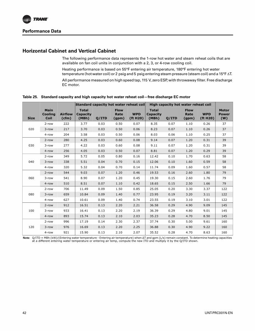
Performance Data
Horizontal Cabinet and Vertical Cabinet
The following performance data represents the 1-row hot water and steam reheat coils that are available on fan coil units in conjunction with a 2, 3, or 4-row cooling coil.
Heating performance is based on 55°F entering air temperature, 180°F entering hot water temperature (hot water coil) or 2 psig and 5 psig entering steam pressure (steam coil) and a 15°F ΔT.
All performance measured on high speed tap, 115 V, zero ESP, with throwaway filter. Free discharge EC motor.
Table 25. Standard capacity and high capacity hot water reheat coil—free discharge EC motor
Size
Main Cooling
CoilAirflow (cfm)
Standard capacity hot water reheat coil High capacity hot water reheat coil
Motor Power (W)
Total Capacity(MBh) Q/ITD
Flow Rate
(gpm)WPD
(ft H20)
Total Capacity(MBh) Q/ITD
Flow Rate
(gpm)WPD
(ft H20)
020
2-row 222 3.77 0.03 0.50 0.07 8.35 0.07 1.10 0.26 37
3-row 217 3.70 0.03 0.50 0.06 8.23 0.07 1.10 0.26 37
4-row 204 3.58 0.03 0.50 0.06 8.03 0.06 1.10 0.25 37
030
2-row 280 4.25 0.03 0.60 0.08 9.14 0.07 1.20 0.31 39
3-row 277 4.22 0.03 0.60 0.08 9.11 0.07 1.20 0.31 39
4-row 256 4.05 0.03 0.50 0.07 8.81 0.07 1.20 0.29 39
040
2-row 349 5.72 0.05 0.80 0.16 12.42 0.10 1.70 0.63 58
3-row 338 5.51 0.04 0.70 0.15 12.06 0.10 1.60 0.59 58
4-row 320 5.32 0.04 0.70 0.14 11.74 0.09 1.60 0.57 58
060
2-row 544 9.03 0.07 1.20 0.46 19.53 0.16 2.60 1.80 79
3-row 541 8.90 0.07 1.20 0.45 19.30 0.15 2.60 1.76 79
4-row 510 8.51 0.07 1.10 0.42 18.65 0.15 2.50 1.66 79
080
2-row 706 11.49 0.09 1.50 0.85 25.05 0.20 3.30 3.37 122
3-row 659 10.84 0.09 1.40 0.77 23.95 0.19 3.20 3.11 122
4-row 627 10.61 0.09 1.40 0.74 23.55 0.19 3.10 3.01 122
100
2-row 912 16.51 0.13 2.20 2.21 36.58 0.29 4.90 9.09 145
3-row 933 16.41 0.13 2.20 2.19 36.39 0.29 4.80 9.01 145
4-row 893 15.74 0.13 2.10 2.03 35.23 0.28 4.70 8.50 145
120
2-row 996 17.19 0.14 2.30 2.37 37.74 0.30 5.00 9.61 160
3-row 976 16.69 0.13 2.20 2.25 36.88 0.30 4.90 9.22 160
4-row 921 15.90 0.13 2.10 2.07 35.52 0.28 4.70 8.63 160
Note: Q/ITD = MBh (kW)/(Entering water temperature - Entering air temperature) when ∆T and gpm (L/s) remain constant. To determine heating capacities at a different entering water temperature or entering air temp, compute the new ITD and multiply it by the Q/ITD shown.
42 UNT-PRC001N-EN
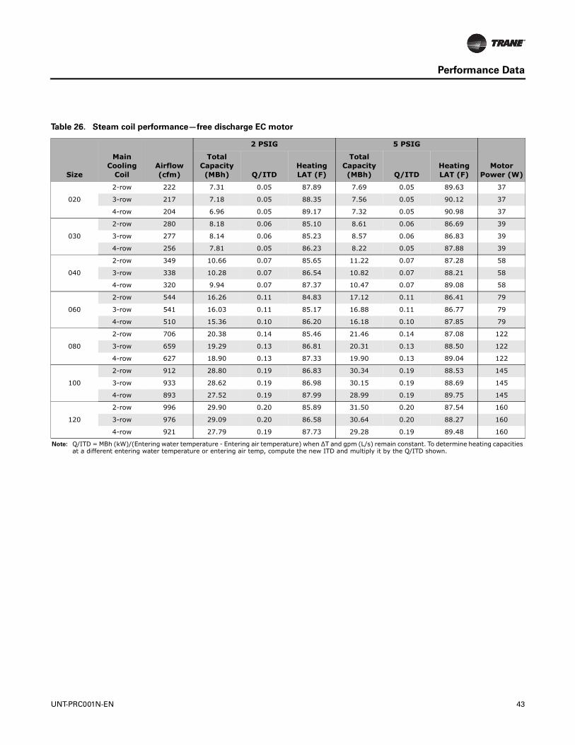
Performance Data
Table 26. Steam coil performance—free discharge EC motor
Size
Main Cooling
CoilAirflow (cfm)
2 PSIG 5 PSIG
Motor Power (W)
Total Capacity(MBh) Q/ITD
Heating LAT (F)
Total Capacity(MBh) Q/ITD
Heating LAT (F)
020
2-row 222 7.31 0.05 87.89 7.69 0.05 89.63 37
3-row 217 7.18 0.05 88.35 7.56 0.05 90.12 37
4-row 204 6.96 0.05 89.17 7.32 0.05 90.98 37
030
2-row 280 8.18 0.06 85.10 8.61 0.06 86.69 39
3-row 277 8.14 0.06 85.23 8.57 0.06 86.83 39
4-row 256 7.81 0.05 86.23 8.22 0.05 87.88 39
040
2-row 349 10.66 0.07 85.65 11.22 0.07 87.28 58
3-row 338 10.28 0.07 86.54 10.82 0.07 88.21 58
4-row 320 9.94 0.07 87.37 10.47 0.07 89.08 58
060
2-row 544 16.26 0.11 84.83 17.12 0.11 86.41 79
3-row 541 16.03 0.11 85.17 16.88 0.11 86.77 79
4-row 510 15.36 0.10 86.20 16.18 0.10 87.85 79
080
2-row 706 20.38 0.14 85.46 21.46 0.14 87.08 122
3-row 659 19.29 0.13 86.81 20.31 0.13 88.50 122
4-row 627 18.90 0.13 87.33 19.90 0.13 89.04 122
100
2-row 912 28.80 0.19 86.83 30.34 0.19 88.53 145
3-row 933 28.62 0.19 86.98 30.15 0.19 88.69 145
4-row 893 27.52 0.19 87.99 28.99 0.19 89.75 145
120
2-row 996 29.90 0.20 85.89 31.50 0.20 87.54 160
3-row 976 29.09 0.20 86.58 30.64 0.20 88.27 160
4-row 921 27.79 0.19 87.73 29.28 0.19 89.48 160
Note: Q/ITD = MBh (kW)/(Entering water temperature - Entering air temperature) when ∆T and gpm (L/s) remain constant. To determine heating capacities at a different entering water temperature or entering air temp, compute the new ITD and multiply it by the Q/ITD shown.
UNT-PRC001N-EN 43

Performance Data
Vertical Slope Top Cabinet
The following performance data represents the 1-row hot water and steam reheat coils that are available on fan coil units in conjunction with a 2, 3, or 4-row cooling coil.
Heating performance is based on 55°F entering air temperature, 180°F entering hot water temperature (hot water coil) or 2 psig and 5 psig entering steam pressure (steam coil) and a 15°F ΔT.
All performance measured on high speed tap, 115 V, zero ESP, with throwaway filter. Free discharge EC motor.
Table 27. Standard capacity and high capacity hot water reheat coil - free discharge EC motor
Size
Main Cooling
CoilAirflow (cfm)
Standard capacity hot water reheat coil High capacity hot water reheat coil
Motor Power (W)
Total Capacity(MBh) Q/ITD
Flow Rate
(gpm)WPD
(ft H20)
Total Capacity(MBh) Q/ITD
Flow Rate
(gpm)WPD
(ft H20)
020
2-row 206 3.64 0.03 0.50 0.06 8.13 0.07 1.10 0.25 37
3-row 200 3.57 0.03 0.50 0.06 8.00 0.06 1.10 0.24 37
4-row 190 3.46 0.03 0.50 0.06 7.82 0.06 1.00 0.23 37
030
2-row 262 4.12 0.03 0.60 0.08 8.94 0.07 1.20 0.30 39
3-row 260 4.10 0.03 0.60 0.08 8.90 0.07 1.20 0.29 39
4-row 242 3.94 0.03 0.50 0.07 8.64 0.07 1.20 0.28 39
040
2-row 330 5.57 0.05 0.70 0.15 12.16 0.10 1.60 0.60 58
3-row 320 5.38 0.04 0.70 0.14 11.84 0.10 1.60 0.57 58
4-row 304 5.21 0.04 0.70 0.14 11.55 0.09 1.50 0.55 58
060
2-row 512 8.76 0.07 1.20 0.44 19.08 0.15 2.50 1.73 79
3-row 508 8.65 0.07 1.20 0.43 18.88 0.15 2.50 1.69 79
4-row 483 8.31 0.07 1.10 0.40 18.30 0.15 2.40 1.60 79
080
2-row 665 11.20 0.09 1.50 0.81 24.55 0.20 3.30 3.25 122
3-row 623 10.61 0.09 1.40 0.74 23.54 0.19 3.10 3.01 122
4-row 596 10.39 0.08 1.40 0.71 23.17 0.19 3.10 2.93 122
100
2-row 856 16.02 0.13 2.10 2.10 35.73 0.29 4.80 8.71 145
3-row 873 15.93 0.13 2.10 2.08 35.57 0.29 4.70 8.65 145
4-row 839 15.33 0.12 2.00 1.94 34.54 0.28 4.60 8.20 145
120
2-row 940 16.74 0.13 2.20 2.27 36.97 0.30 4.90 9.26 160
3-row 923 16.30 0.13 2.20 2.16 36.21 0.29 4.80 8.92 160
4-row 876 15.58 0.13 2.10 2.00 34.98 0.28 4.70 8.38 160
Note: Q/ITD = MBh (kW)/(Entering water temperature - Entering air temperature) when ∆T and gpm (L/s) remain constant. To determine heating capacities at a different entering water temperature or entering air temp, compute the new ITD and multiply it by the Q/ITD shown.
44 UNT-PRC001N-EN

Performance Data
Table 28. Steam coil performance—free discharge EC motor
Size
Main Cooling
CoilAirflow (cfm)
2 PSIG 5 PSIG
Motor Power (W)
Total Capacity(MBh) Q/ITD
Heating LAT (F)
Total Capacity(MBh) Q/ITD
Heating LAT (F)
020
2-row 206 7.06 0.05 88.78 7.44 0.05 90.56 37
3-row 200 6.93 0.05 89.28 7.29 0.05 91.10 37
4-row 190 6.73 0.05 90.04 7.09 0.05 91.89 37
030
2-row 262 7.95 0.05 85.79 8.37 0.05 87.42 39
3-row 260 7.91 0.05 85.90 8.33 0.05 87.53 39
4-row 242 7.62 0.05 86.84 8.02 0.05 88.52 39
040
2-row 330 10.39 0.07 86.29 10.94 0.07 87.94 58
3-row 320 10.04 0.07 87.12 10.57 0.07 88.82 58
4-row 304 9.74 0.07 87.90 10.25 0.07 89.64 58
060
2-row 512 15.80 0.11 85.51 16.64 0.11 87.13 79
3-row 508 15.60 0.11 85.83 16.43 0.11 87.46 79
4-row 483 15.01 0.10 86.77 15.81 0.10 88.46 79
080
2-row 665 19.89 0.13 86.05 20.94 0.13 87.70 122
3-row 623 18.89 0.13 87.34 19.89 0.13 89.05 122
4-row 596 18.53 0.12 87.82 19.51 0.12 89.46 122
100
2-row 856 27.99 0.19 87.55 29.48 0.19 89.29 145
3-row 873 27.84 0.19 87.69 29.33 0.19 89.44 145
4-row 839 26.85 0.18 88.63 28.29 0.18 90.42 145
120
2-row 940 29.17 0.20 86.51 30.73 0.20 88.19 160
3-row 923 28.44 0.19 87.14 29.96 0.19 88.86 160
4-row 876 27.26 0.18 88.23 28.72 0.18 90.00 160
Note: Q/ITD = MBh (kW)/(Entering water temperature - Entering air temperature) when ∆T and gpm (L/s) remain constant. To determine heating capacities at a different entering water temperature or entering air temp, compute the new ITD and multiply it by the Q/ITD shown.
UNT-PRC001N-EN 45

Performance Data
Horizontal Concealed, Compact Concealed, Horizontal Cabinet, Horizontal Recessed, and Vertical Recessed
The following performance data represents the 1-row hot water and steam reheat coils that are available on fan coil units in conjunction with a 2-, 3-, or 4-row cooling coil.
Heating performance is based on 55°F entering air temperature, 180°F entering hot water temperature (hot water coil) or 2 psig and 5 psig entering steam pressure (steam coil) and a 15°F ΔT.
All performance measured on high speed tap, 115 V, 0.20 ESP, without filter. High static EC motor.
Table 29. Standard capacity and high capacity hot water reheat coil - high static EC motor
Size
Main Cooling
CoilAirflow (cfm)
Standard capacity hot water reheat coil High capacity hot water reheat coil
Motor Power (W)
Total Capacity(MBh) Q/ITD
Flow Rate
(gpm)WPD
(ft H20)
Total Capacity(MBh) Q/ITD
Flow Rate
(gpm)WPD
(ft H20)
020
2-row 314 4.62 0.04 0.60 0.09 9.76 0.08 1.30 0.35 84
3-row 319 4.63 0.04 0.60 0.09 9.77 0.08 1.30 0.35 84
4-row 295 4.44 0.04 0.60 0.09 9.47 0.08 1.30 0.33 84
030
2-row 380 5.10 0.04 0.70 0.11 10.52 0.08 1.40 0.39 91
3-row 358 4.91 0.04 0.70 0.10 10.23 0.08 1.40 0.38 91
4-row 330 4.71 0.04 0.60 0.10 9.90 0.08 1.30 0.35 91
040
2-row 410 6.35 0.05 0.90 0.19 13.47 0.11 1.80 0.72 110
3-row 506 6.93 0.06 0.90 0.22 14.41 0.12 1.90 0.81 110
4-row 470 6.64 0.05 0.90 0.21 13.95 0.11 1.90 0.77 110
060
2-row 700 10.50 0.08 1.40 0.60 21.95 0.18 2.90 2.21 162
3-row 824 11.31 0.09 1.50 0.69 23.22 0.19 3.10 2.45 162
4-row 760 10.70 0.09 1.40 0.62 22.27 0.18 3.00 2.27 162
080
2-row 950 13.79 0.11 1.80 1.17 28.87 0.23 3.80 4.33 298
3-row 927 13.32 0.11 1.80 1.10 28.10 0.23 3.70 4.13 298
4-row 870 12.93 0.10 1.70 1.04 27.46 0.22 3.70 3.96 298
100
2-row 1199 19.54 0.16 2.60 2.98 41.72 0.33 5.60 11.49 252
3-row 1360 20.42 0.16 2.70 3.22 43.15 0.35 5.70 12.21 252
4-row 1276 19.44 0.16 2.60 2.95 41.55 0.33 5.50 11.41 252
120
2-row 1330 20.57 0.17 2.70 3.26 43.40 0.35 5.80 12.34 314
3-row 1419 20.85 0.17 2.80 3.34 43.86 0.35 5.80 12.57 314
4-row 1330 19.85 0.16 2.60 3.06 42.22 0.34 5.60 11.75 314
Note: Q/ITD = MBh (kW)/(Entering water temperature - Entering air temperature) when ∆T and gpm (L/s) remain constant. To determine heating capacities at a different entering water temperature or entering air temp, compute the new ITD and multiply it by the Q/ITD shown.
46 UNT-PRC001N-EN

Performance Data
Table 30. Steam coil performance—high static EC motor
Size
Main Cooling
CoilAirflow (cfm)
2 PSIG 5 PSIG
Motor Power (W)
Total Capacity
MBh) Q/ITDHeating LAT (F)
Total Capacity(MBh) Q/ITD
Heating LAT (F)
020
2-row 314 8.88 0.06 83.20 9.35 0.06 84.69 84
3-row 319 8.89 0.06 83.17 9.36 0.06 84.66 84
4-row 295 8.55 0.06 84.07 9.00 0.06 85.61 84
030
2-row 380 9.78 0.07 81.08 10.29 0.07 82.46 91
3-row 358 9.42 0.06 81.88 9.92 0.06 83.29 91
4-row 330 9.04 0.06 82.78 9.52 0.06 84.25 91
040
2-row 410 11.79 0.08 83.28 12.41 0.08 84.78 110
3-row 506 12.84 0.09 81.40 13.52 0.09 82.80 110
4-row 470 12.32 0.08 82.30 12.97 0.08 83.75 110
060
2-row 700 18.81 0.13 81.52 19.81 0.13 82.93 162
3-row 824 20.22 0.14 80.01 21.28 0.14 81.33 162
4-row 760 19.16 0.13 81.13 20.17 0.13 82.52 162
080
2-row 950 24.29 0.16 81.44 25.59 0.16 82.84 298
3-row 927 23.49 0.16 82.17 24.74 0.16 83.62 298
4-row 870 22.82 0.15 82.81 24.04 0.15 84.29 298
100
2-row 1199 33.79 0.23 82.99 35.60 0.23 84.49 252
3-row 1360 35.23 0.24 82.05 37.13 0.24 83.50 252
4-row 1276 33.63 0.23 83.11 35.43 0.23 84.61 252
120
2-row 1330 35.48 0.24 81.89 37.39 0.24 83.34 314
3-row 1419 35.95 0.24 81.60 37.89 0.24 83.03 314
4-row 1330 34.30 0.23 82.65 36.13 0.23 84.14 314
Note: Q/ITD = MBh (kW)/(Entering water temperature - Entering air temperature) when ∆T and gpm (L/s) remain constant. To determine heating capacities at a different entering water temperature or entering air temp, compute the new ITD and multiply it by the Q/ITD shown.
UNT-PRC001N-EN 47

Performance Data
Vertical Concealed
The following performance data represents the 1-row hot water and steam reheat coils that are available on fan coil units in conjunction with a 2-, 3-, or 4-row cooling coil.
Heating performance is based on 55°F entering air temperature, 180°F entering hot water temperature (hot water coil) or 2 psig and 5 psig entering steam pressure (steam coil) and a 15°F ΔT.
All performance measured on high speed tap, 115 V, 0.20 ESP, without filter. High static EC motor.
Table 31. Standard capacity and high capacity hot water reheat coil - high static EC motor
Size
Main Cooling
CoilAirflow (cfm)
Standard capacity hot water reheat coil High capacity hot water reheat coil
Motor Power (W)
Total Capacity(MBh) Q/ITD
Flow Rate
(gpm)WPD
(ft H20)
Total Capacity(MBh) Q/ITD
Flow Rate
(gpm)WPD
(ft H20)
020
2-row 274 4.32 0.04 0.60 0.08 9.26 0.08 1.20 0.32 84
3-row 274 4.30 0.03 0.60 0.08 9.24 0.07 1.20 0.31 84
4-row 258 4.17 0.03 0.60 0.08 9.01 0.07 1.20 0.30 84
030
2-row 341 4.85 0.04 0.70 0.10 10.12 0.08 1.40 0.37 91
3-row 319 4.66 0.04 0.60 0.10 9.83 0.08 1.30 0.35 91
4-row 299 4.50 0.04 0.60 0.09 9.56 0.08 1.30 0.33 91
040
2-row 377 6.09 0.05 0.80 0.18 13.04 0.10 1.70 0.68 110
3-row 455 6.62 0.05 0.90 0.21 13.90 0.11 1.90 0.76 110
4-row 429 6.38 0.05 0.90 0.19 13.52 0.11 1.80 0.73 110
060
2-row 632 9.99 0.08 1.30 0.55 21.12 0.17 2.80 2.07 162
3-row 733 10.72 0.09 1.40 0.62 22.29 0.18 3.00 2.28 162
4-row 687 10.23 0.08 1.40 0.57 21.51 0.17 2.90 2.14 162
080
2-row 865 13.22 0.11 1.80 1.09 27.95 0.22 3.70 4.09 298
3-row 845 12.82 0.10 1.70 1.03 27.28 0.22 3.60 3.92 298
4-row 800 12.48 0.10 1.70 0.98 26.73 0.21 3.60 3.78 298
100
2-row 1089 18.64 0.15 2.50 2.74 40.20 0.32 5.40 10.76 252
3-row 1206 19.36 0.16 2.60 2.93 41.42 0.33 5.50 11.35 252
4-row 1145 18.58 0.15 2.50 2.73 40.11 0.32 5.30 10.72 252
120
2-row 1218 19.73 0.16 2.60 3.03 42.03 0.34 5.60 11.65 314
3-row 1291 20.02 0.16 2.70 3.11 42.50 0.34 5.70 11.88 314
4-row 1223 19.18 0.15 2.60 2.88 41.10 0.33 5.50 11.19 314
Note: Q/ITD = MBh (kW)/(Entering water temperature - Entering air temperature) when ∆T and gpm (L/s) remain constant. To determine heating capacities at a different entering water temperature or entering air temp, compute the new ITD and multiply it by the Q/ITD shown.
48 UNT-PRC001N-EN

Performance Data
Table 32. Steam coil performance—high static EC motor
Size
Main Cooling
CoilAirflow (cfm)
2 PSIG 5 PSIG
Motor Power (W)
Total Capacity(MBh) Q/ITD
Heating LAT (F)
Total Capacity(MBh) Q/ITD
Heating LAT (F)
020
2-row 274 8.32 0.06 84.71 8.76 0.06 86.28 84
3-row 274 8.29 0.06 84.80 8.72 0.06 86.37 84
4-row 258 8.03 0.05 85.55 8.45 0.05 87.17 84
030
2-row 341 9.30 0.06 82.16 9.79 0.06 83.60 91
3-row 319 8.96 0.06 83.00 9.43 0.06 84.48 91
4-row 299 8.65 0.06 83.79 9.11 0.06 85.31 91
040
2-row 377 11.32 0.08 84.21 11.92 0.08 85.76 110
3-row 455 12.27 0.08 82.39 12.92 0.08 83.84 110
4-row 429 11.84 0.08 83.18 12.47 0.08 84.67 110
060
2-row 632 17.92 0.12 82.59 18.87 0.12 84.05 162
3-row 733 19.18 0.13 81.10 20.20 0.13 82.49 162
4-row 687 18.34 0.12 82.08 19.31 0.12 83.52 162
080
2-row 865 23.32 0.16 82.33 24.56 0.16 83.78 298
3-row 845 22.64 0.15 83.00 23.84 0.15 84.49 298
4-row 800 22.07 0.15 83.58 23.24 0.15 85.10 298
100
2-row 1089 32.29 0.22 84.04 34.02 0.22 85.60 252
3-row 1206 33.49 0.23 83.19 35.29 0.23 84.71 252
4-row 1145 32.21 0.22 84.10 33.93 0.22 85.66 252
120
2-row 1218 34.10 0.23 82.78 35.93 0.23 84.28 314
3-row 1291 34.57 0.23 82.47 36.43 0.23 83.95 314
4-row 1223 33.18 0.22 83.41 34.96 0.22 84.93 314
Note: Q/ITD = MBh (kW)/(Entering water temperature - Entering air temperature) when ∆T and gpm (L/s) remain constant. To determine heating capacities at a different entering water temperature or entering air temp, compute the new ITD and multiply it by the Q/ITD shown.
UNT-PRC001N-EN 49
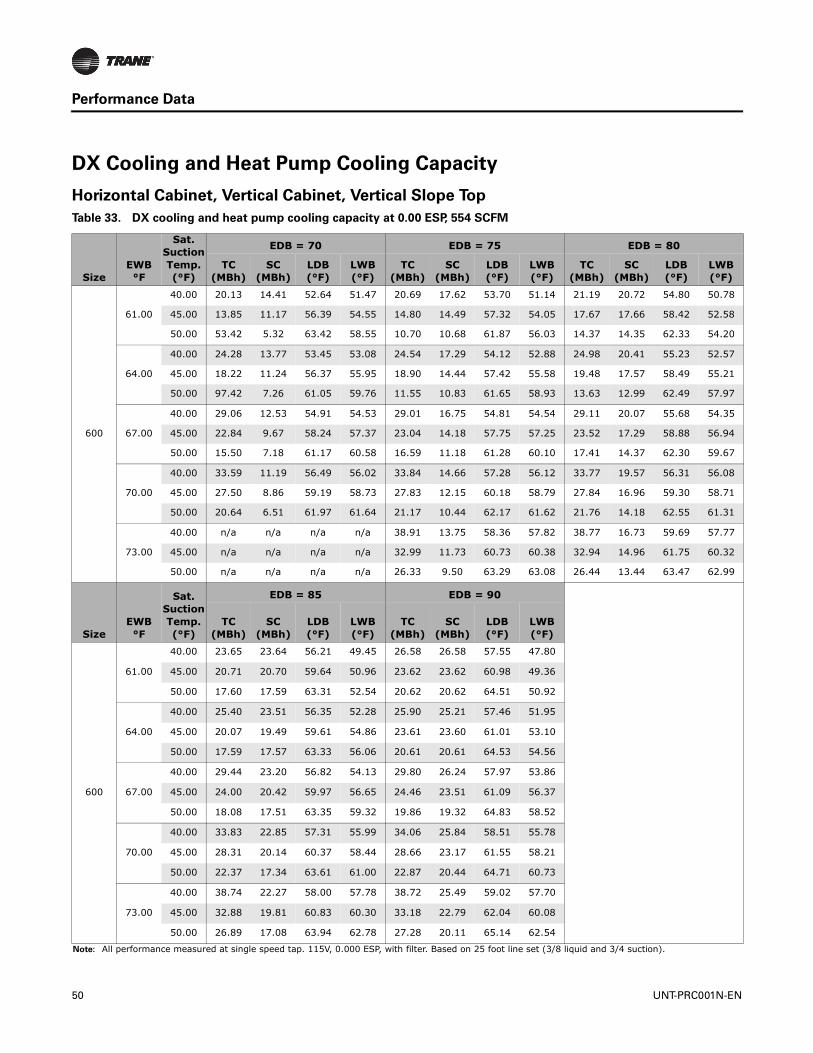
Performance Data
DX Cooling and Heat Pump Cooling Capacity
Horizontal Cabinet, Vertical Cabinet, Vertical Slope Top
Table 33. DX cooling and heat pump cooling capacity at 0.00 ESP, 554 SCFM
SizeEWB°F
Sat. Suction Temp. (°F)
EDB = 70 EDB = 75 EDB = 80
TC (MBh)
SC (MBh)
LDB(°F)
LWB(°F)
TC (MBh)
SC (MBh)
LDB (°F)
LWB(°F)
TC (MBh)
SC (MBh)
LDB(°F)
LWB(°F)
600
61.00
40.00 20.13 14.41 52.64 51.47 20.69 17.62 53.70 51.14 21.19 20.72 54.80 50.78
45.00 13.85 11.17 56.39 54.55 14.80 14.49 57.32 54.05 17.67 17.66 58.42 52.58
50.00 53.42 5.32 63.42 58.55 10.70 10.68 61.87 56.03 14.37 14.35 62.33 54.20
64.00
40.00 24.28 13.77 53.45 53.08 24.54 17.29 54.12 52.88 24.98 20.41 55.23 52.57
45.00 18.22 11.24 56.37 55.95 18.90 14.44 57.42 55.58 19.48 17.57 58.49 55.21
50.00 97.42 7.26 61.05 59.76 11.55 10.83 61.65 58.93 13.63 12.99 62.49 57.97
67.00
40.00 29.06 12.53 54.91 54.53 29.01 16.75 54.81 54.54 29.11 20.07 55.68 54.35
45.00 22.84 9.67 58.24 57.37 23.04 14.18 57.75 57.25 23.52 17.29 58.88 56.94
50.00 15.50 7.18 61.17 60.58 16.59 11.18 61.28 60.10 17.41 14.37 62.30 59.67
70.00
40.00 33.59 11.19 56.49 56.02 33.84 14.66 57.28 56.12 33.77 19.57 56.31 56.08
45.00 27.50 8.86 59.19 58.73 27.83 12.15 60.18 58.79 27.84 16.96 59.30 58.71
50.00 20.64 6.51 61.97 61.64 21.17 10.44 62.17 61.62 21.76 14.18 62.55 61.31
73.00
40.00 n/a n/a n/a n/a 38.91 13.75 58.36 57.82 38.77 16.73 59.69 57.77
45.00 n/a n/a n/a n/a 32.99 11.73 60.73 60.38 32.94 14.96 61.75 60.32
50.00 n/a n/a n/a n/a 26.33 9.50 63.29 63.08 26.44 13.44 63.47 62.99
SizeEWB°F
Sat. Suction Temp. (°F)
EDB = 85 EDB = 90
TC (MBh)
SC (MBh)
LDB(°F)
LWB(°F)
TC (MBh)
SC (MBh)
LDB (°F)
LWB(°F)
600
61.00
40.00 23.65 23.64 56.21 49.45 26.58 26.58 57.55 47.80
45.00 20.71 20.70 59.64 50.96 23.62 23.62 60.98 49.36
50.00 17.60 17.59 63.31 52.54 20.62 20.62 64.51 50.92
64.00
40.00 25.40 23.51 56.35 52.28 25.90 25.21 57.46 51.95
45.00 20.07 19.49 59.61 54.86 23.61 23.60 61.01 53.10
50.00 17.59 17.57 63.33 56.06 20.61 20.61 64.53 54.56
67.00
40.00 29.44 23.20 56.82 54.13 29.80 26.24 57.97 53.86
45.00 24.00 20.42 59.97 56.65 24.46 23.51 61.09 56.37
50.00 18.08 17.51 63.35 59.32 19.86 19.32 64.83 58.52
70.00
40.00 33.83 22.85 57.31 55.99 34.06 25.84 58.51 55.78
45.00 28.31 20.14 60.37 58.44 28.66 23.17 61.55 58.21
50.00 22.37 17.34 63.61 61.00 22.87 20.44 64.71 60.73
73.00
40.00 38.74 22.27 58.00 57.78 38.72 25.49 59.02 57.70
45.00 32.88 19.81 60.83 60.30 33.18 22.79 62.04 60.08
50.00 26.89 17.08 63.94 62.78 27.28 20.11 65.14 62.54
Note: All performance measured at single speed tap. 115V, 0.000 ESP, with filter. Based on 25 foot line set (3/8 liquid and 3/4 suction).
50 UNT-PRC001N-EN

Performance Data
Table 34. DX cooling and heat pump cooling capacity at 0.00 ESP, 738 SCFM
SizeEWB°F
Sat. Suction Temp. (°F)
EDB = 70 EDB = 75 EDB = 80
TC (MBh)
SC (MBh)
LDB(°F)
LWB(°F)
TC (MBh)
SC (MBh)
LDB (°F)
LWB(°F)
TC (MBh)
SC (MBh)
LDB(°F)
LWB(°F)
800
61.00
40.00 27.18 19.30 52.15 51.10 27.72 23.46 53.28 50.86 28.23 27.58 54.41 50.60
45.00 20.07 15.68 55.51 53.87 20.81 19.88 56.59 53.56 23.77 23.76 58.02 52.41
50.00 10.36 9.93 60.08 57.43 15.84 15.83 60.41 55.46 20.00 19.98 61.52 53.87
64.00
40.00 32.47 18.19 53.22 52.76 32.82 23.03 53.74 52.61 33.25 27.12 54.91 52.38
45.00 25.15 15.34 55.87 55.54 25.81 19.53 56.96 55.24 26.38 23.67 58.10 54.99
50.00 16.86 11.42 59.48 58.46 18.06 15.83 60.41 58.03 19.03 18.08 61.59 57.66
67.00
40.00 38.48 16.73 54.59 54.35 38.54 22.13 54.63 54.31 38.77 26.68 55.39 54.16
45.00 31.10 13.42 57.68 57.07 31.44 19.28 57.31 56.94 31.72 23.21 58.55 56.72
50.00 22.51 10.00 60.81 60.01 23.43 15.56 60.68 59.67 24.18 19.70 61.82 59.35
70.00
40.00 44.23 14.64 56.56 55.92 44.69 19.67 57.01 56.11 44.68 25.88 56.27 56.01
45.00 36.97 11.96 58.97 58.49 37.50 16.43 59.92 58.60 37.52 22.81 59.02 58.52
50.00 28.81 9.07 61.68 61.29 29.15 14.10 62.03 61.35 29.82 19.32 62.21 61.08
73.00
40.00 n/a n/a n/a n/a 51.07 18.05 58.44 57.92 51.14 22.34 59.55 57.88
45.00 n/a n/a n/a n/a 44.14 15.67 60.70 60.36 44.03 19.98 61.65 60.22
50.00 n/a n/a n/a n/a 35.91 12.87 63.15 62.87 36.05 18.12 63.37 62.81
SizeEWB°F
Sat. Suction Temp. (°F)
EDB = 85 EDB = 90
TC (MBh)
SC (MBh)
LDB(°F)
LWB(°F)
TC (MBh)
SC (MBh)
LDB (°F)
LWB(°F)
800
61.00
40.00 31.44 31.42 55.85 49.28 35.16 35.15 57.33 47.70
45.00 27.72 27.70 59.31 50.82 31.51 31.50 60.73 49.25
50.00 23.92 23.90 62.84 52.34 27.77 27.77 64.21 50.79
64.00
40.00 33.70 31.21 56.07 52.16 34.20 33.11 57.26 51.93
45.00 26.96 26.17 59.28 54.73 31.56 31.55 60.79 53.01
50.00 23.96 23.93 62.89 55.89 27.82 27.81 64.26 54.45
67.00
40.00 38.95 30.67 56.66 54.04 39.34 34.77 57.82 53.85
45.00 32.19 27.32 59.74 56.52 32.68 31.48 60.88 56.32
50.00 24.80 23.84 62.97 59.11 26.68 25.48 64.39 58.51
70.00
40.00 44.68 30.22 57.22 55.95 44.94 34.19 58.44 55.79
45.00 37.85 26.88 60.25 58.36 38.25 30.98 61.41 58.17
50.00 30.36 23.43 63.39 60.86 30.90 27.61 64.54 60.67
73.00
40.00 50.93 29.35 58.01 57.83 50.96 33.62 59.09 57.77
45.00 43.92 26.45 60.76 60.26 44.19 30.41 61.98 60.08
50.00 36.36 23.04 63.83 62.68 36.83 27.14 65.02 62.48
Note: All performance measured at single speed tap. 115V, 0.000 ESP, with filter. Based on 25 foot line set (3/8 liquid and 3/4 suction).
UNT-PRC001N-EN 51
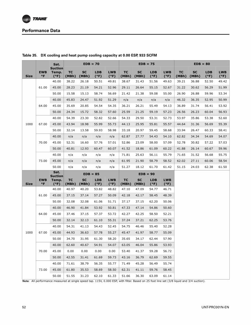
Performance Data
Table 35. DX cooling and heat pump cooling capacity at 0.00 ESP, 933 SCFM
SizeEWB°F
Sat. Suction Temp. (°F)
EDB = 70 EDB = 75 EDB = 80
TC (MBh)
SC (MBh)
LDB(°F)
LWB(°F)
TC (MBh)
SC (MBh)
LDB (°F)
LWB(°F)
TC (MBh)
SC (MBh)
LDB(°F)
LWB(°F)
1000
61.00
40.00 38.22 26.18 50.51 49.81 38.67 31.43 51.56 49.63 39.21 36.88 52.50 49.42
45.00 28.23 21.19 54.21 52.96 29.11 26.64 55.15 52.67 31.22 30.62 56.29 51.99
50.00 15.58 15.13 58.74 56.69 21.42 21.38 59.08 55.00 26.90 26.88 59.96 53.34
64.00
40.00 45.83 24.47 51.92 51.29 n/a n/a n/a n/a 46.32 36.35 52.95 50.99
45.00 35.69 20.85 54.54 54.35 36.21 26.21 55.49 54.13 36.89 31.74 56.41 53.92
50.00 24.34 15.72 58.32 57.60 25.59 21.25 59.19 57.23 26.56 26.23 60.04 56.93
67.00
40.00 54.39 23.30 52.82 52.66 54.33 29.50 53.31 52.73 53.97 35.86 53.38 52.60
45.00 43.94 18.98 55.99 55.73 44.13 25.95 55.81 55.57 44.64 31.36 56.69 55.39
50.00 32.14 13.58 59.93 58.98 33.18 20.97 59.45 58.68 33.94 26.47 60.33 58.41
70.00
40.00 n/a n/a n/a n/a 62.87 27.77 54.43 54.10 62.82 34.34 54.69 54.07
45.00 52.31 16.60 57.76 57.01 52.86 23.09 58.00 57.09 52.78 30.82 57.22 57.03
50.00 40.81 12.93 60.47 60.07 41.52 18.86 61.09 60.22 41.88 26.14 60.67 59.96
73.00
40.00 n/a n/a n/a n/a 71.81 25.63 56.11 55.79 71.65 31.52 56.68 55.75
45.00 n/a n/a n/a n/a 61.95 21.90 58.79 58.52 62.02 27.11 60.06 58.54
50.00 n/a n/a n/a n/a 51.27 18.12 61.70 61.42 51.15 24.03 62.38 61.50
SizeEWB°F
Sat. Suction Temp. (°F)
EDB = 85 EDB = 90
TC (MBh)
SC (MBh)
LDB(°F)
LWB(°F)
TC (MBh)
SC (MBh)
LDB (°F)
LWB(°F)
1000
61.00
40.00 40.97 40.20 53.82 48.82 47.10 47.09 54.77 46.71
45.00 37.15 37.14 57.27 50.09 42.18 42.17 58.45 48.39
50.00 32.08 32.08 61.06 51.71 37.17 37.15 62.20 50.06
64.00
40.00 46.90 41.84 53.92 50.81 47.33 47.14 54.86 50.60
45.00 37.46 37.15 57.37 53.72 42.27 42.25 58.50 52.21
50.00 32.14 32.13 61.10 55.31 37.24 37.21 62.25 53.76
67.00
40.00 54.31 41.13 54.43 52.45 54.75 46.46 55.40 52.28
45.00 44.93 36.63 57.78 55.27 45.47 41.97 58.77 55.09
50.00 34.70 31.95 61.30 58.20 35.65 34.17 62.44 57.90
70.00
40.00 62.60 40.67 54.91 54.07 63.05 46.04 55.86 53.93
45.00 0.00 0.00 0.00 0.00 53.40 41.37 59.28 56.72
50.00 42.55 31.41 61.69 59.73 43.16 36.79 62.69 59.55
73.00
40.00 71.61 38.79 56.35 55.77 71.49 45.28 56.49 55.74
45.00 61.80 35.53 58.69 58.50 62.31 41.11 59.76 58.45
50.00 51.55 31.23 62.10 61.33 51.66 36.30 63.09 61.14
Note: All performance measured at single speed tap. 115V, 0.000 ESP, with filter. Based on 25 foot line set (3/8 liquid and 3/4 suction).
52 UNT-PRC001N-EN

Performance Data
Table 36. DX cooling and heat pump cooling capacity at 0.00 ESP, 1108 SCFM
SizeEWB°F
Sat. Suction Temp. (°F)
EDB = 70 EDB = 75 EDB = 80
TC (MBh)
SC (MBh)
LDB(°F)
LWB(°F)
TC (MBh)
SC (MBh)
LDB (°F)
LWB(°F)
TC (MBh)
SC (MBh)
LDB(°F)
LWB(°F)
1200
61.00
40.00 48.35 33.07 49.05 48.84 49.10 40.03 49.59 48.57 49.75 46.99 50.21 48.39
45.00 36.50 27.25 52.84 52.14 37.45 34.25 53.29 51.80 39.50 38.68 54.19 51.13
50.00 22.30 20.67 57.15 55.82 27.56 27.56 57.41 54.34 34.51 34.49 57.98 52.51
64.00
40.00 57.76 31.12 50.60 50.36 58.27 39.27 50.31 50.15 58.51 45.98 50.84 49.83
45.00 45.46 25.51 54.09 53.58 46.29 33.60 53.78 53.19 47.00 40.42 54.38 52.93
50.00 31.33 20.34 57.37 57.07 33.38 27.64 57.61 56.47 34.40 34.27 58.15 56.13
67.00
40.00 67.56 28.02 52.30 51.55 67.76 36.58 51.96 51.51 68.04 45.05 51.57 51.35
45.00 55.15 23.54 55.31 54.89 55.82 31.39 55.30 54.68 56.49 39.60 54.92 54.33
50.00 40.36 18.18 58.80 58.60 42.80 27.07 58.15 57.92 43.65 33.81 58.65 57.52
70.00
40.00 77.90 27.00 53.43 53.03 78.54 34.15 53.64 53.13 78.58 42.29 53.49 52.94
45.00 65.53 21.44 56.54 56.00 66.60 29.92 56.51 56.24 66.71 37.36 56.69 56.00
50.00 51.17 16.18 59.94 59.50 52.81 24.83 59.58 59.41 53.88 33.29 59.17 58.96
73.00
40.00 n/a n/a n/a n/a 89.39 31.37 55.39 54.66 n/a n/a n/a n/a
45.00 n/a n/a n/a n/a 77.87 26.87 58.23 57.49 77.60 35.41 57.89 57.53
50.00 n/a n/a n/a n/a 64.36 21.78 61.50 60.66 64.25 30.65 60.90 60.57
SizeEWB°F
Sat. Suction Temp. (°F)
EDB = 85 EDB = 90
TC (MBh)
SC (MBh)
LDB(°F)
LWB(°F)
TC (MBh)
SC (MBh)
LDB (°F)
LWB(°F)
1200
61.00
40.00 52.00 51.19 51.28 47.67 59.78 59.77 51.98 45.39
45.00 47.38 47.36 54.82 48.99 53.69 53.68 55.79 47.17
50.00 41.00 40.97 58.80 50.74 47.42 47.41 59.73 48.96
64.00
40.00 59.13 52.90 51.51 49.67 59.79 59.62 52.18 49.53
45.00 47.75 47.34 55.06 52.74 53.79 53.77 55.85 51.08
50.00 41.05 41.01 58.86 54.40 47.51 47.49 59.76 52.74
67.00
40.00 68.50 51.88 52.18 51.18 68.92 58.81 52.88 51.09
45.00 57.08 46.44 55.61 54.17 57.74 53.49 56.24 54.02
50.00 44.49 40.74 59.24 57.28 45.44 43.11 59.91 57.07
70.00
40.00 78.56 50.82 53.07 52.86 78.62 57.71 53.63 52.77
45.00 66.90 45.48 56.23 55.68 67.48 52.50 56.86 55.56
50.00 54.36 39.96 59.76 58.72 55.11 47.05 60.34 58.55
73.00
40.00 89.03 47.24 55.36 54.54 89.58 56.49 54.80 54.61
45.00 78.06 42.90 58.29 57.41 78.42 51.84 57.64 57.24
50.00 65.08 39.08 60.44 60.21 65.52 46.17 60.89 60.04
Note: All performance measured at single speed tap. 115V, 0.000 ESP, with filter. Based on 25 foot line set (3/8 liquid and 3/4 suction).
UNT-PRC001N-EN 53
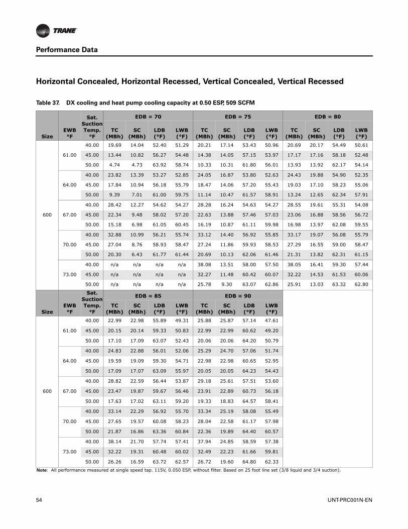
Performance Data
Horizontal Concealed, Horizontal Recessed, Vertical Concealed, Vertical Recessed
Table 37. DX cooling and heat pump cooling capacity at 0.50 ESP, 509 SCFM
SizeEWB°F
Sat. Suction Temp.
°F
EDB = 70 EDB = 75 EDB = 80
TC (MBh)
SC (MBh)
LDB(°F)
LWB(°F)
TC (MBh)
SC (MBh)
LDB (°F)
LWB(°F)
TC (MBh)
SC (MBh)
LDB(°F)
LWB(°F)
600
61.00
40.00 19.69 14.04 52.40 51.29 20.21 17.14 53.43 50.96 20.69 20.17 54.49 50.61
45.00 13.44 10.82 56.27 54.48 14.38 14.05 57.15 53.97 17.17 17.16 58.18 52.48
50.00 4.74 4.73 63.92 58.74 10.33 10.31 61.80 56.01 13.93 13.92 62.17 54.14
64.00
40.00 23.82 13.39 53.27 52.85 24.05 16.87 53.80 52.63 24.43 19.88 54.90 52.35
45.00 17.84 10.94 56.18 55.79 18.47 14.06 57.20 55.43 19.03 17.10 58.23 55.06
50.00 9.39 7.01 61.00 59.75 11.14 10.47 61.57 58.91 13.24 12.65 62.34 57.91
67.00
40.00 28.42 12.27 54.62 54.27 28.28 16.24 54.63 54.27 28.55 19.61 55.31 54.08
45.00 22.34 9.48 58.02 57.20 22.63 13.88 57.46 57.03 23.06 16.88 58.56 56.72
50.00 15.18 6.98 61.05 60.45 16.19 10.87 61.11 59.98 16.98 13.97 62.08 59.55
70.00
40.00 32.88 10.99 56.21 55.74 33.12 14.40 56.92 55.85 33.17 19.07 56.08 55.79
45.00 27.04 8.76 58.93 58.47 27.24 11.86 59.93 58.53 27.29 16.55 59.00 58.47
50.00 20.30 6.43 61.77 61.44 20.69 10.13 62.06 61.46 21.31 13.82 62.31 61.15
73.00
40.00 n/a n/a n/a n/a 38.08 13.51 58.00 57.50 38.05 16.41 59.30 57.44
45.00 n/a n/a n/a n/a 32.27 11.48 60.42 60.07 32.22 14.53 61.53 60.06
50.00 n/a n/a n/a n/a 25.78 9.30 63.07 62.86 25.91 13.03 63.32 62.80
SizeEWB°F
Sat. Suction Temp.
°F
EDB = 85 EDB = 90
TC (MBh)
SC (MBh)
LDB(°F)
LWB(°F)
TC (MBh)
SC (MBh)
LDB (°F)
LWB(°F)
600
61.00
40.00 22.99 22.98 55.89 49.31 25.88 25.87 57.14 47.61
45.00 20.15 20.14 59.33 50.83 22.99 22.99 60.62 49.20
50.00 17.10 17.09 63.07 52.43 20.06 20.06 64.20 50.79
64.00
40.00 24.83 22.88 56.01 52.06 25.29 24.70 57.06 51.74
45.00 19.59 19.09 59.30 54.71 22.98 22.98 60.65 52.95
50.00 17.09 17.07 63.09 55.97 20.05 20.05 64.23 54.43
67.00
40.00 28.82 22.59 56.44 53.87 29.18 25.61 57.51 53.60
45.00 23.47 19.87 59.67 56.46 23.91 22.89 60.73 56.18
50.00 17.63 17.02 63.11 59.20 19.33 18.83 64.57 58.41
70.00
40.00 33.14 22.29 56.92 55.70 33.34 25.19 58.08 55.49
45.00 27.65 19.57 60.08 58.23 28.04 22.58 61.17 57.98
50.00 21.87 16.86 63.36 60.84 22.36 19.89 64.40 60.57
73.00
40.00 38.14 21.70 57.74 57.41 37.94 24.85 58.59 57.38
45.00 32.22 19.31 60.48 60.02 32.49 22.23 61.66 59.81
50.00 26.26 16.59 63.72 62.57 26.72 19.60 64.80 62.33
Note: All performance measured at single speed tap. 115V, 0.050 ESP, without filter. Based on 25 foot line set (3/8 liquid and 3/4 suction).
54 UNT-PRC001N-EN

Performance Data
Table 38. DX cooling and heat pump cooling capacity at 0.50 ESP, 679 SCFM
SizeEWB°F
Sat. Suction Temp.
°F
EDB = 70 EDB = 75 EDB = 80
TC (MBh)
SC (MBh)
LDB(°F)
LWB(°F)
TC (MBh)
SC (MBh)
LDB (°F)
LWB(°F)
TC (MBh)
SC (MBh)
LDB(°F)
LWB(°F)
800
61.00
40.00 26.61 18.81 51.89 50.89 27.07 22.80 52.99 50.65 27.55 26.81 54.07 50.40
45.00 19.58 15.24 55.32 53.74 20.30 19.31 56.36 53.42 23.03 23.02 57.81 52.32
50.00 9.98 9.59 60.05 57.41 15.35 15.34 60.26 55.40 19.42 19.41 61.30 53.78
64.00
40.00 31.77 17.67 53.01 52.52 32.12 22.43 53.41 52.35 32.52 26.40 54.54 52.13
45.00 24.65 14.97 55.65 55.35 25.23 18.99 56.71 55.07 25.76 23.01 57.81 54.81
50.00 16.44 11.08 59.35 58.37 17.60 15.36 60.24 57.93 18.53 17.66 61.36 57.56
67.00
40.00 37.67 16.39 54.27 54.06 37.74 21.51 54.43 54.06 37.87 25.96 55.06 53.91
45.00 30.41 13.15 57.43 56.87 30.68 18.73 57.05 56.73 31.03 22.61 58.23 56.50
50.00 22.06 9.74 60.69 59.88 22.93 15.15 60.48 59.52 23.62 19.16 61.56 59.20
70.00
40.00 43.41 14.37 56.23 55.67 43.63 19.22 56.52 55.72 43.58 25.04 56.00 55.68
45.00 36.15 11.73 58.72 58.25 36.64 16.04 59.63 58.34 36.72 22.23 58.67 58.24
50.00 28.19 8.93 61.49 61.12 28.55 13.68 61.88 61.16 29.23 18.84 61.93 60.88
73.00
40.00 n/a n/a n/a n/a 50.10 17.77 58.06 57.56 50.07 21.91 58.98 57.44
45.00 n/a n/a n/a n/a 43.01 15.26 60.37 59.99 43.06 19.42 61.45 60.00
50.00 n/a n/a n/a n/a 35.10 12.57 62.92 62.65 35.25 17.55 63.21 62.59
SizeEWB°F
Sat. Suction Temp.
°F
EDB = 85 EDB = 90
TC (MBh)
SC (MBh)
LDB(°F)
LWB(°F)
TC (MBh)
SC (MBh)
LDB (°F)
LWB(°F)
800
61.00
40.00 30.55 30.54 55.47 49.12 34.19 34.18 56.88 47.49
45.00 26.94 26.93 58.96 50.67 30.63 30.63 60.34 49.07
50.00 23.24 23.23 62.55 52.21 26.98 26.98 63.89 50.65
64.00
40.00 32.88 30.32 55.70 51.93 33.38 32.47 56.83 51.69
45.00 26.32 25.66 58.94 54.56 30.68 30.68 60.40 52.85
50.00 23.28 23.26 62.59 55.77 27.04 27.04 63.92 54.30
67.00
40.00 38.08 29.84 56.26 53.75 38.45 33.83 57.38 53.57
45.00 31.46 26.56 59.39 56.30 31.93 30.60 60.50 56.10
50.00 24.22 23.16 62.68 58.96 25.97 24.83 64.04 58.37
70.00
40.00 43.74 29.42 56.84 55.66 43.99 33.31 57.96 55.47
45.00 36.98 26.12 59.91 58.10 37.38 30.13 61.02 57.92
50.00 29.70 22.78 63.08 60.66 30.20 26.83 64.21 60.47
73.00
40.00 49.98 28.60 57.72 57.52 49.92 32.78 58.62 57.42
45.00 43.02 25.75 60.36 59.92 43.19 29.59 61.60 59.81
50.00 35.60 22.42 63.51 62.41 35.99 26.39 64.67 62.26
Note: All performance measured at single speed tap. 115V, 0.050 ESP, without filter. Based on 25 foot line set (3/8 liquid and 3/4 suction).
UNT-PRC001N-EN 55

Performance Data
Table 39. DX cooling and heat pump cooling capacity at 0.50 ESP, 849 SCFM
SizeEWB°F
Sat. Suction Temp.
°F
EDB = 70 EDB = 75 EDB = 80
TC (MBh)
SC (MBh)
LDB(°F)
LWB(°F)
TC (MBh)
SC (MBh)
LDB (°F)
LWB(°F)
TC (MBh)
SC (MBh)
LDB(°F)
LWB(°F)
1000
61.00
40.00 36.94 25.31 50.33 49.70 37.54 30.51 51.27 49.48 38.07 35.77 52.19 49.26
45.00 27.41 20.60 54.00 52.85 28.26 25.85 54.90 52.56 30.23 29.59 56.01 51.90
50.00 14.87 14.58 58.70 56.72 20.73 20.69 58.94 54.94 26.08 26.05 59.75 53.25
64.00
40.00 44.64 23.66 51.81 51.10 n/a n/a n/a n/a 45.00 35.27 52.62 50.79
45.00 34.52 20.10 54.41 54.23 35.31 25.53 55.17 53.96 35.86 30.80 56.15 53.78
50.00 23.62 15.29 58.19 57.54 24.82 20.61 59.02 57.15 25.76 25.47 59.83 56.84
67.00
40.00 52.88 22.65 52.63 52.47 0.00 0.00 0.00 0.00 52.76 35.02 53.04 52.36
45.00 42.75 18.53 55.75 55.55 42.89 25.09 55.63 55.38 43.09 30.30 56.54 55.29
50.00 31.20 13.14 59.79 58.86 32.31 20.39 59.24 58.54 32.98 25.67 60.11 58.28
70.00
40.00 60.60 19.63 54.80 53.72 61.10 27.11 54.05 53.83 60.98 33.00 54.53 53.81
45.00 50.95 16.06 57.59 56.79 51.52 22.63 57.61 56.84 51.63 29.97 56.89 56.72
50.00 39.71 12.58 60.33 59.91 40.41 18.19 60.98 59.97 41.04 25.47 60.37 59.75
73.00
40.00 n/a n/a n/a n/a 70.10 25.06 55.79 55.51 69.77 30.86 56.21 55.46
45.00 n/a n/a n/a n/a 60.51 21.42 58.60 58.32 60.44 26.34 59.76 58.30
50.00 n/a n/a n/a n/a 49.80 17.59 61.49 61.29 49.66 23.07 62.29 61.19
SizeEWB°F
Sat. Suction Temp.
°F
EDB = 85 EDB = 90
TC (MBh)
SC (MBh)
LDB(°F)
LWB(°F)
TC (MBh)
SC (MBh)
LDB (°F)
LWB(°F)
1000
61.00
40.00 39.66 38.68 53.39 48.69 45.71 45.71 54.35 46.52
45.00 36.04 36.04 56.94 49.94 40.92 40.92 58.08 48.23
50.00 31.12 31.11 60.78 51.60 36.06 36.05 61.88 49.92
64.00
40.00 45.49 40.57 53.53 50.61 45.97 45.73 54.46 50.41
45.00 36.37 36.03 57.06 53.58 41.01 41.00 58.13 52.06
50.00 31.18 31.18 60.82 55.20 36.12 36.11 61.93 53.64
67.00
40.00 53.04 40.09 53.93 52.14 53.23 45.16 54.97 52.05
45.00 43.67 35.57 57.45 55.10 44.18 40.74 58.40 54.91
50.00 33.66 30.98 61.04 58.08 34.56 33.17 62.16 57.79
70.00
40.00 61.02 39.64 54.52 53.84 61.09 44.58 55.54 53.73
45.00 n/a n/a n/a n/a 51.92 40.17 58.88 56.52
50.00 41.36 30.51 61.40 59.58 41.96 35.75 62.35 59.40
73.00
40.00 70.02 37.52 56.22 55.44 69.55 43.98 56.03 55.43
45.00 60.62 34.67 58.39 58.19 60.63 39.94 59.37 58.19
50.00 49.86 30.20 61.80 61.15 50.19 35.21 62.77 60.96
Note: All performance measured at single speed tap. 115V, 0.050 ESP, without filter. Based on 25 foot line set (3/8 liquid and 3/4 suction).
56 UNT-PRC001N-EN

Performance Data
Table 40. DX cooling and heat pump cooling capacity at 0.50 ESP, 1019 SCFM
SizeEWB°F
Sat. Suction Temp
°F
EDB = 70 EDB = 75 EDB = 80
TC (MBh)
SC (MBh)
LDB(°F)
LWB(°F)
TC (MBh)
SC (MBh)
LDB (°F)
LWB(°F)
TC (MBh)
SC (MBh)
LDB(°F)
LWB(°F)
1200
61.00
40.00 47.77 32.25 48.73 48.49 48.21 38.83 49.26 48.24 48.86 45.68 49.88 48.11
45.00 36.09 26.55 52.47 51.80 36.91 33.29 52.98 51.54 38.59 37.60 53.72 51.00
50.00 22.60 20.35 56.70 55.46 26.88 26.86 57.10 54.23 33.61 33.60 57.62 52.37
64.00
40.00 56.70 30.38 49.96 49.76 57.22 38.22 49.85 49.66 57.45 44.73 50.46 49.48
45.00 44.87 24.97 53.61 53.15 45.54 32.66 53.42 52.86 46.24 39.34 54.03 52.65
50.00 31.82 20.22 56.87 56.60 33.04 26.98 57.24 56.19 33.91 33.67 57.80 55.91
67.00
40.00 66.56 27.68 51.78 51.08 66.64 35.78 51.46 51.05 67.02 43.98 51.18 50.99
45.00 54.98 23.26 54.82 54.38 55.00 30.67 54.81 54.23 55.44 38.46 54.57 54.00
50.00 41.11 18.30 58.13 57.92 42.40 26.39 57.68 57.49 43.05 32.95 58.27 57.23
70.00
40.00 76.59 26.64 52.77 52.55 77.22 33.57 53.15 52.59 77.14 41.25 53.06 52.48
45.00 64.88 21.64 55.65 55.41 65.57 29.34 55.70 55.48 65.56 36.45 56.06 55.40
50.00 51.68 16.38 59.41 58.93 52.35 24.36 58.98 58.76 53.11 32.33 58.75 58.54
73.00
40.00 n/a n/a n/a n/a 87.88 30.96 54.75 54.04 87.74 39.44 54.20 54.01
45.00 n/a n/a n/a n/a 76.52 26.49 57.63 56.87 76.44 34.80 57.22 56.88
50.00 n/a n/a n/a n/a 63.70 21.68 60.89 60.14 63.74 30.19 60.39 60.10
SizeEWB°F
Sat. Suction Temp
°F
EDB = 85 EDB = 90
TC (MBh)
SC (MBh)
LDB(°F)
LWB(°F)
TC (MBh)
SC (MBh)
LDB (°F)
LWB(°F)
1200
61.00
40.00 50.52 49.45 50.86 47.55 58.11 58.10 51.61 45.23
45.00 46.15 46.14 54.48 48.85 52.20 52.19 55.44 47.03
50.00 39.89 39.87 58.49 50.62 46.24 46.23 59.37 48.81
64.00
40.00 58.02 51.38 51.14 49.34 58.60 58.18 51.82 49.23
45.00 46.94 46.08 54.73 52.49 52.30 52.28 55.49 50.94
50.00 39.98 39.95 58.53 54.28 46.34 46.31 59.42 52.60
67.00
40.00 67.21 50.38 51.85 50.82 67.60 57.07 52.50 50.72
45.00 56.06 45.10 55.27 53.85 56.63 51.90 55.90 53.72
50.00 43.78 39.63 58.93 57.05 44.62 42.82 59.62 56.86
70.00
40.00 77.04 49.39 52.55 52.34 77.15 56.01 53.21 52.32
45.00 65.82 44.19 55.88 55.30 66.26 50.93 56.51 55.20
50.00 53.52 38.83 59.40 58.40 54.15 45.63 60.03 58.26
73.00
40.00 87.72 46.24 54.84 54.02 87.59 54.70 54.17 53.95
45.00 76.41 41.81 57.64 56.86 76.82 50.22 57.19 56.81
50.00 64.21 38.12 59.99 59.78 64.55 44.83 60.51 59.66
Note: All performance measured at single speed tap. 115V, 0.050 ESP, without filter. Based on 25 foot line set (3/8 liquid and 3/4 suction).
UNT-PRC001N-EN 57
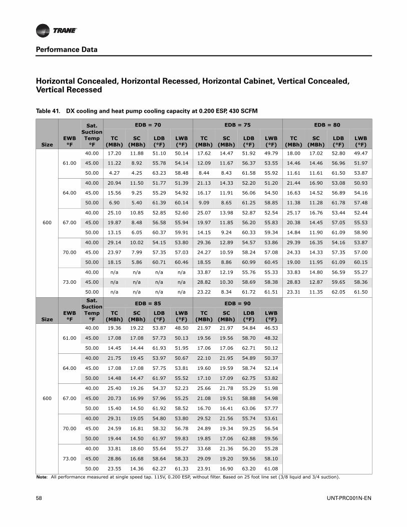
Performance Data
Horizontal Concealed, Horizontal Recessed, Horizontal Cabinet, Vertical Concealed, Vertical Recessed
Table 41. DX cooling and heat pump cooling capacity at 0.200 ESP, 430 SCFM
SizeEWB°F
Sat. Suction Temp
°F
EDB = 70 EDB = 75 EDB = 80
TC (MBh)
SC (MBh)
LDB(°F)
LWB(°F)
TC (MBh)
SC (MBh)
LDB (°F)
LWB(°F)
TC (MBh)
SC (MBh)
LDB(°F)
LWB(°F)
600
61.00
40.00 17.20 11.88 51.10 50.14 17.62 14.47 51.92 49.79 18.00 17.02 52.80 49.47
45.00 11.22 8.92 55.78 54.14 12.09 11.67 56.37 53.55 14.46 14.46 56.96 51.97
50.00 4.27 4.25 63.23 58.48 8.44 8.43 61.58 55.92 11.61 11.61 61.50 53.87
64.00
40.00 20.94 11.50 51.77 51.39 21.13 14.33 52.20 51.20 21.44 16.90 53.08 50.93
45.00 15.56 9.25 55.29 54.92 16.17 11.91 56.06 54.50 16.63 14.52 56.89 54.16
50.00 6.90 5.40 61.39 60.14 9.09 8.65 61.25 58.85 11.38 11.28 61.78 57.48
67.00
40.00 25.10 10.85 52.85 52.60 25.07 13.98 52.87 52.54 25.17 16.76 53.44 52.44
45.00 19.87 8.48 56.58 55.94 19.97 11.85 56.20 55.83 20.38 14.45 57.05 55.53
50.00 13.15 6.05 60.37 59.91 14.15 9.24 60.33 59.34 14.84 11.90 61.09 58.90
70.00
40.00 29.14 10.02 54.15 53.80 29.36 12.89 54.57 53.86 29.39 16.35 54.16 53.87
45.00 23.97 7.99 57.35 57.03 24.27 10.59 58.24 57.08 24.33 14.33 57.35 57.00
50.00 18.15 5.86 60.71 60.46 18.55 8.86 60.99 60.45 19.00 11.95 61.09 60.15
73.00
40.00 n/a n/a n/a n/a 33.87 12.19 55.76 55.33 33.83 14.80 56.59 55.27
45.00 n/a n/a n/a n/a 28.82 10.30 58.69 58.38 28.83 12.87 59.65 58.36
50.00 n/a n/a n/a n/a 23.22 8.34 61.72 61.51 23.31 11.35 62.05 61.50
SizeEWB°F
Sat. Suction Temp
°F
EDB = 85 EDB = 90
TC (MBh)
SC (MBh)
LDB(°F)
LWB(°F)
TC (MBh)
SC (MBh)
LDB (°F)
LWB(°F)
600
61.00
40.00 19.36 19.22 53.87 48.50 21.97 21.97 54.84 46.53
45.00 17.08 17.08 57.73 50.13 19.56 19.56 58.70 48.32
50.00 14.45 14.44 61.93 51.95 17.06 17.06 62.71 50.12
64.00
40.00 21.75 19.45 53.97 50.67 22.10 21.95 54.89 50.37
45.00 17.08 17.08 57.75 53.81 19.60 19.59 58.74 52.14
50.00 14.48 14.47 61.97 55.52 17.10 17.09 62.75 53.82
67.00
40.00 25.40 19.26 54.37 52.23 25.66 21.78 55.29 51.98
45.00 20.73 16.99 57.96 55.25 21.08 19.51 58.88 54.98
50.00 15.40 14.50 61.92 58.52 16.70 16.41 63.06 57.77
70.00
40.00 29.31 19.05 54.80 53.80 29.52 21.56 55.74 53.61
45.00 24.59 16.81 58.32 56.78 24.89 19.34 59.25 56.54
50.00 19.44 14.50 61.97 59.83 19.85 17.06 62.88 59.56
73.00
40.00 33.81 18.60 55.64 55.27 33.68 21.36 56.20 55.28
45.00 28.86 16.68 58.64 58.33 29.09 19.20 59.56 58.10
50.00 23.55 14.36 62.27 61.33 23.91 16.90 63.20 61.08
Note: All performance measured at single speed tap. 115V, 0.200 ESP, without filter. Based on 25 foot line set (3/8 liquid and 3/4 suction).
58 UNT-PRC001N-EN

Performance Data
Table 42. DX cooling and heat pump cooling capacity at 0.200 ESP, 573 SCFM
SizeEWB°F
Sat. Suction Temp
°F
EDB = 70 EDB = 75 EDB = 80
TC (MBh)
SC (MBh)
LDB(°F)
LWB(°F)
TC (MBh)
SC (MBh)
LDB (°F)
LWB(°F)
TC (MBh)
SC (MBh)
LDB(°F)
LWB(°F)
800
61.00
40.00 23.68 16.26 50.56 49.72 24.01 19.60 51.52 49.50 24.37 22.98 52.45 49.27
45.00 17.28 13.08 54.38 53.01 17.88 16.51 55.23 52.67 19.66 19.52 56.33 51.77
50.00 8.34 8.22 59.94 57.29 12.89 12.87 59.64 55.15 16.55 16.54 60.25 53.35
64.00
40.00 28.42 15.51 51.54 51.15 28.63 19.37 51.88 50.96 28.85 22.69 52.87 50.78
45.00 21.97 12.96 54.59 54.36 22.51 16.37 55.43 54.02 22.86 19.73 56.40 53.81
50.00 14.37 9.44 58.75 57.88 15.38 13.04 59.44 57.39 16.17 15.82 60.31 57.00
67.00
40.00 33.63 14.59 52.62 52.43 33.65 18.69 52.80 52.43 33.69 22.41 53.30 52.34
45.00 27.21 11.74 56.05 55.60 27.29 16.12 55.83 55.52 27.64 19.49 56.75 55.28
50.00 19.71 8.64 59.73 59.00 20.47 13.02 59.51 58.66 21.00 16.46 60.36 58.34
70.00
40.00 38.84 13.21 54.33 53.80 39.17 17.35 54.46 53.91 39.11 21.78 54.18 53.86
45.00 32.36 10.77 57.20 56.79 32.70 14.35 57.91 56.89 32.83 19.29 57.09 56.80
50.00 25.17 8.13 60.32 60.03 25.64 12.02 60.74 60.07 26.10 16.29 60.67 59.84
73.00
40.00 n/a n/a n/a n/a 44.81 16.14 55.86 55.45 44.67 19.73 56.58 55.45
45.00 n/a n/a n/a n/a 38.67 13.82 58.65 58.33 38.50 17.22 59.51 58.26
50.00 n/a n/a n/a n/a 31.62 11.36 61.53 61.35 31.54 15.23 61.89 61.26
SizeEWB°F
Sat. Suction Temp
°F
EDB = 85 EDB = 90
TC (MBh)
SC (MBh)
LDB(°F)
LWB(°F)
TC (MBh)
SC (MBh)
LDB (°F)
LWB(°F)
800
61.00
40.00 26.00 25.84 53.70 48.40 29.41 29.41 54.70 46.47
45.00 23.15 23.15 57.29 49.94 26.31 26.30 58.44 48.20
50.00 19.93 19.92 61.16 51.63 23.15 23.14 62.23 49.92
64.00
40.00 29.16 26.08 53.78 50.58 29.51 29.42 54.71 50.35
45.00 23.27 23.14 57.32 53.57 26.36 26.34 58.49 52.03
50.00 19.96 19.95 61.21 55.22 23.19 23.18 62.28 53.63
67.00
40.00 33.95 25.77 54.25 52.15 34.19 29.08 55.21 51.98
45.00 27.97 22.87 57.69 55.08 28.31 26.21 58.65 54.89
50.00 21.49 19.88 61.27 58.09 22.65 22.05 62.38 57.60
70.00
40.00 39.04 25.42 54.75 53.78 39.22 28.70 55.77 53.66
45.00 33.05 22.57 58.09 56.63 33.31 25.89 59.11 56.47
50.00 26.46 19.61 61.61 59.58 26.86 22.99 62.57 59.38
73.00
40.00 44.71 24.69 55.69 55.41 44.79 28.42 56.27 55.35
45.00 38.57 22.31 58.50 58.20 38.78 25.60 59.55 58.09
50.00 31.88 19.38 61.99 61.13 32.14 22.67 62.99 60.95
Note: All performance measured at single speed tap. 115V, 0.200 ESP, without filter. Based on 25 foot line set (3/8 liquid and 3/4 suction).
UNT-PRC001N-EN 59

Performance Data
Table 43. DX cooling and heat pump cooling capacity at 0.200 ESP, 717 SCFM
SizeEWB°F
Sat. Suction Temp
°F
EDB = 70 EDB = 75 EDB = 80
TC (MBh)
SC (MBh)
LDB(°F)
LWB(°F)
TC (MBh)
SC (MBh)
LDB (°F)
LWB(°F)
TC (MBh)
SC (MBh)
LDB(°F)
LWB(°F)
1000
61.00
40.00 32.06 21.61 49.21 48.56 32.58 26.06 49.92 48.34 33.01 30.46 50.66 48.11
45.00 23.64 17.49 53.17 52.13 24.40 21.98 53.87 51.81 26.08 25.84 54.66 51.08
50.00 11.62 11.57 58.88 56.81 17.23 17.20 58.46 54.67 21.98 21.96 58.85 52.76
64.00
40.00 38.77 20.72 50.27 49.73 38.96 25.87 50.18 49.54 39.23 30.20 51.01 49.40
45.00 29.99 17.26 53.37 53.18 30.52 21.73 54.10 53.01 31.06 26.16 54.85 52.76
50.00 19.96 12.81 57.68 57.09 21.17 17.37 58.30 56.62 22.03 21.93 58.95 56.28
67.00
40.00 46.06 19.98 50.96 50.82 45.88 24.83 51.32 50.80 0.00 0.00 0.00 0.00
45.00 37.32 16.29 54.54 54.38 37.52 21.62 54.35 54.17 37.75 25.97 55.06 53.96
50.00 27.37 11.78 58.86 58.07 27.95 17.32 58.34 57.70 28.67 21.81 59.05 57.40
70.00
40.00 52.93 18.18 52.55 51.85 53.36 23.89 52.13 51.93 53.47 28.89 52.59 52.03
45.00 44.47 14.84 55.89 55.27 44.96 19.97 55.99 55.35 45.20 25.87 55.48 55.29
50.00 34.91 11.42 59.15 58.88 35.19 16.07 59.67 58.89 35.42 21.51 59.33 58.71
73.00
40.00 n/a n/a n/a n/a 61.56 22.57 53.60 53.43 61.44 27.61 53.92 53.41
45.00 n/a n/a n/a n/a 53.04 19.24 56.85 56.69 n/a n/a n/a n/a
50.00 n/a n/a n/a n/a 43.28 15.55 60.13 59.95 43.29 20.17 60.78 59.95
SizeEWB°F
Sat. Suction Temp
°F
EDB = 85 EDB = 90
TC (MBh)
SC (MBh)
LDB(°F)
LWB(°F)
TC (MBh)
SC (MBh)
LDB (°F)
LWB(°F)
1000
61.00
40.00 34.37 34.04 51.54 47.47 38.93 38.92 52.39 45.37
45.00 30.65 30.64 55.44 49.11 34.81 34.81 56.37 47.26
50.00 26.40 26.39 59.54 50.93 30.65 30.64 60.39 49.10
64.00
40.00 39.50 34.50 51.79 49.21 39.87 38.90 52.54 49.03
45.00 31.55 30.58 55.60 52.54 34.89 34.88 56.41 51.15
50.00 26.47 26.44 59.57 54.56 30.71 30.71 60.44 52.87
67.00
40.00 46.23 34.27 52.08 50.50 46.33 38.54 52.97 50.42
45.00 37.98 30.27 55.94 53.85 38.36 34.70 56.67 53.68
50.00 29.25 26.28 59.77 57.18 30.10 29.58 60.65 56.85
70.00
40.00 53.51 34.07 52.58 51.98 53.26 38.14 53.41 51.85
45.00 45.09 30.07 56.19 55.14 45.23 34.35 57.08 55.05
50.00 36.02 26.00 60.07 58.48 36.51 30.45 60.83 58.30
73.00
40.00 61.65 32.99 53.78 53.29 61.20 38.09 53.84 53.39
45.00 0.00 0.00 0.00 0.00 53.24 34.47 57.47 56.49
50.00 43.41 25.87 60.38 59.83 43.97 30.23 61.07 59.59
Note: All performance measured at single speed tap. 115V, 0.200 ESP, without filter. Based on 25 foot line set (3/8 liquid and 3/4 suction).
60 UNT-PRC001N-EN
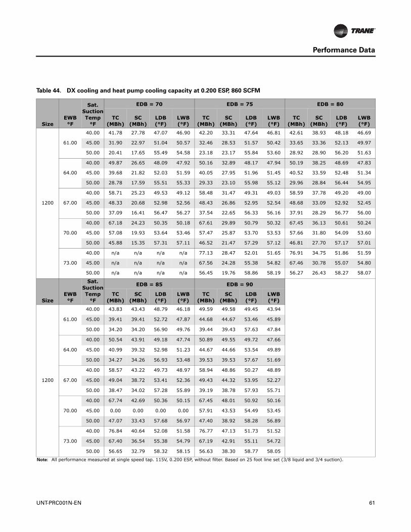
Performance Data
Table 44. DX cooling and heat pump cooling capacity at 0.200 ESP, 860 SCFM
SizeEWB°F
Sat. Suction Temp
°F
EDB = 70 EDB = 75 EDB = 80
TC (MBh)
SC (MBh)
LDB(°F)
LWB(°F)
TC (MBh)
SC (MBh)
LDB (°F)
LWB(°F)
TC (MBh)
SC (MBh)
LDB(°F)
LWB(°F)
1200
61.00
40.00 41.78 27.78 47.07 46.90 42.20 33.31 47.64 46.81 42.61 38.93 48.18 46.69
45.00 31.90 22.97 51.04 50.57 32.46 28.53 51.57 50.42 33.65 33.36 52.13 49.97
50.00 20.41 17.65 55.49 54.58 23.18 23.17 55.84 53.60 28.92 28.90 56.20 51.63
64.00
40.00 49.87 26.65 48.09 47.92 50.16 32.89 48.17 47.94 50.19 38.25 48.69 47.83
45.00 39.68 21.82 52.03 51.59 40.05 27.95 51.96 51.45 40.52 33.59 52.48 51.34
50.00 28.78 17.59 55.51 55.33 29.33 23.10 55.98 55.12 29.96 28.84 56.44 54.95
67.00
40.00 58.71 25.23 49.53 49.12 58.48 31.47 49.31 49.03 58.59 37.78 49.20 49.00
45.00 48.33 20.68 52.98 52.56 48.43 26.86 52.95 52.54 48.68 33.09 52.92 52.45
50.00 37.09 16.41 56.47 56.27 37.54 22.65 56.33 56.16 37.91 28.29 56.77 56.00
70.00
40.00 67.18 24.23 50.35 50.18 67.61 29.89 50.79 50.32 67.45 36.13 50.61 50.24
45.00 57.08 19.93 53.64 53.46 57.47 25.87 53.70 53.53 57.66 31.80 54.09 53.60
50.00 45.88 15.35 57.31 57.11 46.52 21.47 57.29 57.12 46.81 27.70 57.17 57.01
73.00
40.00 n/a n/a n/a n/a 77.13 28.47 52.01 51.65 76.91 34.75 51.86 51.59
45.00 n/a n/a n/a n/a 67.56 24.28 55.38 54.82 67.46 30.78 55.07 54.80
50.00 n/a n/a n/a n/a 56.45 19.76 58.86 58.19 56.27 26.43 58.27 58.07
SizeEWB°F
Sat. Suction Temp
°F
EDB = 85 EDB = 90
TC (MBh)
SC (MBh)
LDB(°F)
LWB(°F)
TC (MBh)
SC (MBh)
LDB (°F)
LWB(°F)
1200
61.00
40.00 43.83 43.43 48.79 46.18 49.59 49.58 49.45 43.94
45.00 39.41 39.41 52.72 47.87 44.68 44.67 53.46 45.89
50.00 34.20 34.20 56.90 49.76 39.44 39.43 57.63 47.84
64.00
40.00 50.54 43.91 49.18 47.74 50.89 49.55 49.72 47.66
45.00 40.99 39.32 52.98 51.23 44.67 44.66 53.54 49.89
50.00 34.27 34.26 56.93 53.48 39.53 39.53 57.67 51.69
67.00
40.00 58.57 43.22 49.73 48.97 58.94 48.86 50.27 48.89
45.00 49.04 38.72 53.41 52.36 49.43 44.32 53.95 52.27
50.00 38.47 34.02 57.28 55.89 39.19 38.78 57.93 55.71
70.00
40.00 67.74 42.69 50.36 50.15 67.45 48.01 50.92 50.16
45.00 0.00 0.00 0.00 0.00 57.91 43.53 54.49 53.45
50.00 47.07 33.43 57.68 56.97 47.40 38.92 58.28 56.89
73.00
40.00 76.84 40.64 52.08 51.58 76.77 47.13 51.73 51.52
45.00 67.40 36.54 55.38 54.79 67.19 42.91 55.11 54.72
50.00 56.65 32.79 58.32 58.15 56.63 38.30 58.77 58.05
Note: All performance measured at single speed tap. 115V, 0.200 ESP, without filter. Based on 25 foot line set (3/8 liquid and 3/4 suction).
UNT-PRC001N-EN 61

Performance Data
Heat Pump Heating Capacity
Horizontal Cabinet, Vertical Cabinet, Vertical Slope Top Cabinet
Table 45. Heat pump heating capacity at 0.000 ESP, 734 SCFM
SizeEWB°F
Sat. Disch Temp
°F
EDB = 70 EDB = 75 EDB = 80
TC (MBh)
SC (MBh)
LDB(°F)
LWB(°F)
TC (MBh)
SC (MBh)
LDB (°F)
LWB(°F)
TC (MBh)
SC (MBh)
LDB(°F)
LWB(°F)
600
61.00
100.00 12.53 12.53 85.50 66.18 8.97 8.97 86.12 64.77 5.38 5.38 86.68 63.30
110.00 20.71 20.71 95.61 69.29 16.55 16.55 95.52 67.75 12.72 12.72 95.80 66.27
120.00 29.19 29.19 106.11 72.31 25.07 25.07 106.07 70.88 20.95 20.95 106.02 69.41
64.00
100.00 12.57 12.57 85.49 68.89 9.00 9.00 86.12 67.55 5.39 5.39 86.67 66.16
110.00 20.79 20.79 95.62 71.83 16.61 16.61 95.52 70.37 12.76 12.76 95.79 68.97
120.00 29.30 29.30 106.12 74.69 25.15 25.15 106.06 73.33 21.04 21.04 106.03 71.94
67.00
100.00 12.61 12.61 85.48 71.60 9.03 9.03 86.11 70.34 5.41 5.41 86.67 69.03
110.00 20.87 20.87 95.62 74.39 16.68 16.68 95.52 73.00 12.80 12.80 95.79 71.68
120.00 29.42 29.42 106.11 77.10 25.25 25.25 106.07 75.81 21.11 21.11 106.01 74.48
70.00
100.00 12.65 12.65 85.47 74.32 9.06 9.06 86.10 73.14 5.43 5.43 86.66 71.90
110.00 20.94 20.94 95.61 76.96 16.75 16.75 95.52 75.65 12.85 12.85 95.78 74.40
120.00 29.54 29.54 106.13 79.53 25.37 25.37 106.07 78.30 21.20 21.20 106.02 77.05
73.00
100.00 n/a n/a n/a n/a 9.09 9.09 86.09 75.94 5.45 5.45 86.66 74.79
110.00 n/a n/a n/a n/a 16.82 16.82 95.52 78.31 12.90 12.90 95.77 77.13
120.00 n/a n/a n/a n/a 25.49 25.49 106.08 80.82 21.30 21.30 106.03 79.64
SizeEWB°F
Sat. Disch Temp
°F
EDB = 85 EDB = 90
TC (MBh)
SC (MBh)
LDB(°F)
LWB(°F)
TC (MBh)
SC (MBh)
LDB (°F)
LWB(°F)
600
61.00
100.00 n/a n/a n/a n/a n/a n/a n/a n/a
110.00 9.14 9.14 96.38 64.85 5.55 5.55 96.92 63.37
120.00 16.81 16.81 105.91 67.86 12.95 12.95 106.15 66.38
64.00
100.00 n/a n/a n/a n/a n/a n/a n/a n/a
110.00 9.17 9.17 96.37 67.63 5.56 5.56 96.91 66.23
120.00 16.87 16.87 105.92 70.47 12.99 12.99 106.14 69.07
67.00
100.00 n/a n/a n/a n/a n/a n/a n/a n/a
110.00 9.20 9.20 96.37 70.41 5.58 5.58 96.91 69.10
120.00 16.93 16.93 105.92 73.10 13.04 13.04 106.14 71.77
70.00
100.00 n/a n/a n/a n/a n/a n/a n/a n/a
110.00 9.23 9.23 96.36 73.20 5.60 5.60 96.90 71.97
120.00 17.01 17.01 105.92 75.74 13.09 13.09 106.13 74.49
73.00
100.00 n/a n/a n/a n/a n/a n/a n/a n/a
110.00 9.27 9.27 96.35 76.01 5.62 5.62 96.90 74.85
120.00 17.09 17.09 105.92 78.40 13.14 13.14 106.12 77.21
Note: All performance measured at single speed tap. 115V, 0.000 ESP, with filter. Based on 25 foot line set (3/8 liquid and 3/4 suction).
62 UNT-PRC001N-EN

Performance Data
Table 46. Heat pump heating capacity at 0.000 ESP, 979 SCFM
SizeEWB°F
Sat. Disch Temp
°F
EDB = 70 EDB = 75 EDB = 80
TC (MBh)
SC (MBh)
LDB(°F)
LWB(°F)
TC (MBh)
SC (MBh)
LDB (°F)
LWB(°F)
TC (MBh)
SC (MBh)
LDB(°F)
LWB(°F)
800
61.00
100.00 16.87 16.87 85.65 66.23 12.19 12.19 86.33 64.84 7.42 7.42 86.91 63.37
110.00 27.60 27.60 95.60 69.29 22.12 22.12 95.56 67.76 17.10 17.10 95.93 66.32
120.00 38.92 38.92 106.10 72.31 33.42 33.42 106.06 70.88 27.93 27.93 106.01 69.40
64.00
100.00 16.86 16.86 85.58 68.91 12.23 12.23 86.33 67.61 7.44 7.44 86.90 66.23
110.00 27.71 27.71 95.60 71.82 22.20 22.20 95.55 70.38 17.16 17.16 95.92 69.01
120.00 39.07 39.07 106.10 74.69 33.55 33.55 106.06 73.33 28.04 28.04 106.01 71.93
67.00
100.00 16.98 16.98 85.64 71.64 12.27 12.27 86.32 70.40 7.47 7.47 86.90 69.10
110.00 27.81 27.81 95.60 74.38 22.28 22.28 95.55 73.01 17.16 17.16 95.86 71.70
120.00 39.23 39.23 106.11 77.10 33.68 33.68 106.06 75.81 28.17 28.17 106.04 74.48
70.00
100.00 17.04 17.04 85.62 74.36 12.31 12.31 86.31 73.19 7.49 7.49 86.90 71.97
110.00 27.94 27.94 95.62 76.96 22.37 22.37 95.55 75.66 17.26 17.26 95.89 74.43
120.00 39.38 39.38 106.10 79.52 33.83 33.83 106.07 78.30 28.29 28.29 106.04 77.05
73.00
100.00 n/a n/a n/a n/a 12.36 12.36 86.30 76.00 7.48 7.48 86.85 74.84
110.00 n/a n/a n/a n/a 22.47 22.47 95.55 78.32 17.33 17.33 95.88 77.16
120.00 n/a n/a n/a n/a 33.99 33.99 106.07 80.82 28.43 28.43 106.05 79.64
SizeEWB°F
Sat. Disch Temp
°F
EDB = 85 EDB = 90
TC (MBh)
SC (MBh)
LDB(°F)
LWB(°F)
TC (MBh)
SC (MBh)
LDB (°F)
LWB(°F)
800
61.00
100.00 n/a n/a n/a n/a n/a n/a n/a n/a
110.00 12.39 12.39 96.56 64.91 7.61 7.61 97.11 63.44
120.00 22.46 22.46 105.95 67.87 17.38 17.38 106.25 66.41
64.00
100.00 n/a n/a n/a n/a n/a n/a n/a n/a
110.00 12.43 12.43 96.56 67.68 7.64 7.64 97.12 66.30
120.00 22.53 22.53 105.95 70.48 17.44 17.44 106.24 69.10
67.00
100.00 n/a n/a n/a n/a n/a n/a n/a n/a
110.00 12.47 12.47 96.55 70.46 7.68 7.68 97.13 69.16
120.00 22.62 22.62 105.95 73.11 17.50 17.50 106.24 71.80
70.00
100.00 n/a n/a n/a n/a n/a n/a n/a n/a
110.00 12.51 12.51 96.54 73.25 7.71 7.71 97.12 72.03
120.00 22.71 22.71 105.95 75.75 17.56 17.56 106.23 74.51
73.00
100.00 n/a n/a n/a n/a n/a n/a n/a n/a
110.00 12.56 12.56 96.53 76.05 7.74 7.74 97.12 74.90
120.00 22.82 22.82 105.95 78.41 17.63 17.63 106.22 77.24
Note: All performance measured at single speed tap. 115V, 0.000 ESP, with filter. Based on 25 foot line set (3/8 liquid and 3/4 suction).
UNT-PRC001N-EN 63

Performance Data
Table 47. Heat pump heating capacity at 0.000 ESP, 1224 SCFM
SizeEWB°F
Sat. Disch Temp
°F
EDB = 70 EDB = 75 EDB = 80
TC (MBh)
SC (MBh)
LDB(°F)
LWB(°F)
TC (MBh)
SC (MBh)
LDB (°F)
LWB(°F)
TC (MBh)
SC (MBh)
LDB(°F)
LWB(°F)
1000
61.00
100.00 22.29 22.29 86.54 66.52 15.67 15.67 86.65 64.95 7.69 7.69 85.73 62.98
110.00 35.54 35.54 96.36 69.52 28.99 28.99 96.55 68.07 22.51 22.51 96.77 66.58
120.00 49.21 49.21 106.50 72.43 42.48 42.48 106.58 71.03 35.85 35.85 106.70 69.61
64.00
100.00 22.37 22.37 86.54 69.20 15.72 15.72 86.64 67.72 7.72 7.72 85.73 65.86
110.00 35.66 35.66 96.36 72.04 29.08 29.08 96.54 70.67 22.58 22.58 96.76 69.26
120.00 49.38 49.38 106.49 74.80 42.64 42.64 106.58 73.48 35.97 35.97 106.69 72.13
67.00
100.00 22.45 22.45 86.53 71.90 15.77 15.77 86.64 70.50 7.77 7.77 85.74 68.75
110.00 35.80 35.80 96.35 74.59 29.19 29.19 96.54 73.28 22.67 22.67 96.76 71.96
120.00 49.57 49.57 106.49 77.20 42.80 42.80 106.57 75.94 36.10 36.10 106.68 74.66
70.00
100.00 22.53 22.53 86.53 74.61 15.83 15.83 86.63 73.29 7.81 7.81 85.75 71.65
110.00 35.91 35.91 96.34 77.14 29.31 29.31 96.53 75.92 22.76 22.76 96.75 74.66
120.00 49.76 49.76 106.49 79.62 42.99 42.99 106.58 78.43 36.15 36.15 106.61 77.20
73.00
100.00 n/a n/a n/a n/a 15.87 15.87 86.61 76.08 7.85 7.85 85.75 74.55
110.00 n/a n/a n/a n/a 29.43 29.43 96.53 78.57 22.85 22.85 96.75 77.38
120.00 n/a n/a n/a n/a 43.18 43.18 106.58 80.95 36.31 36.31 106.61 79.78
SizeEWB°F
Sat. Disch Temp
°F
EDB = 85 EDB = 90
TC (MBh)
SC (MBh)
LDB(°F)
LWB(°F)
TC (MBh)
SC (MBh)
LDB (°F)
LWB(°F)
1000
61.00
100.00 n/a n/a n/a n/a n/a n/a n/a n/a
110.00 15.90 15.90 96.87 65.02 8.30 8.30 96.21 63.14
120.00 29.27 29.27 106.84 68.15 22.78 22.78 107.03 66.66
64.00
100.00 n/a n/a n/a n/a n/a n/a n/a n/a
110.00 15.96 15.96 96.87 67.78 8.33 8.33 96.21 66.01
120.00 29.37 29.37 106.84 70.75 22.85 22.85 107.03 69.34
67.00
100.00 n/a n/a n/a n/a n/a n/a n/a n/a
110.00 16.02 16.02 96.87 70.56 8.37 8.37 96.21 68.89
120.00 29.46 29.46 106.82 73.35 22.94 22.94 107.02 72.02
70.00
100.00 n/a n/a n/a n/a n/a n/a n/a n/a
110.00 16.09 16.09 96.87 73.35 8.44 8.44 96.24 71.78
120.00 29.57 29.57 106.81 75.98 23.03 23.03 107.02 74.73
73.00
100.00 n/a n/a n/a n/a n/a n/a n/a n/a
110.00 16.16 16.16 96.87 76.14 8.48 8.48 96.24 74.68
120.00 29.73 29.73 106.83 78.63 23.13 23.13 107.02 77.44
Note: All performance measured at single speed tap. 115V, 0.000 ESP, with filter. Based on 25 foot line set (3/8 liquid and 3/4 suction).
64 UNT-PRC001N-EN

Performance Data
Table 48. Heat pump heating capacity at 0.000 ESP, 1468 SCFM
SizeEWB°F
Sat. Disch Temp
°F
EDB = 70 EDB = 75 EDB = 80
TC (MBh)
SC (MBh)
LDB(°F)
LWB(°F)
TC (MBh)
SC (MBh)
LDB (°F)
LWB(°F)
TC (MBh)
SC (MBh)
LDB(°F)
LWB(°F)
1200
61.00
100.00 27.37 27.37 86.92 66.63 19.49 19.49 87.08 65.08 10.86 10.86 86.74 63.31
110.00 43.14 43.14 96.68 69.60 35.36 35.36 96.91 68.17 27.64 27.64 97.16 66.70
120.00 59.19 59.19 106.60 72.44 51.33 51.33 106.80 71.08 43.46 43.46 106.98 69.68
64.00
100.00 27.46 27.46 86.92 69.31 19.56 19.56 87.08 67.84 10.90 10.90 86.74 66.18
110.00 43.23 43.23 96.64 72.11 35.47 35.47 96.90 70.76 27.73 27.73 97.15 69.37
120.00 59.43 59.43 106.61 74.82 51.51 51.51 106.80 73.52 43.60 43.60 106.97 72.19
67.00
100.00 27.56 27.56 86.91 72.00 19.63 19.63 87.07 70.61 10.94 10.94 86.74 69.04
110.00 43.42 43.42 96.65 74.65 35.61 35.61 96.90 73.37 27.83 27.83 97.15 72.06
120.00 59.69 59.69 106.63 77.22 51.70 51.70 106.79 75.99 43.76 43.76 106.96 74.72
70.00
100.00 27.65 27.65 86.91 74.70 19.71 19.71 87.07 73.40 11.00 11.00 86.75 71.92
110.00 43.57 43.57 96.64 77.21 35.75 35.75 96.89 76.00 27.94 27.94 97.14 74.76
120.00 59.91 59.91 106.62 79.64 51.90 51.90 106.78 78.47 43.98 43.98 106.98 77.28
73.00
100.00 n/a n/a n/a n/a 19.80 19.80 87.07 76.19 11.05 11.05 86.75 74.80
110.00 n/a n/a n/a n/a 35.90 35.90 96.88 78.64 28.05 28.05 97.14 77.47
120.00 n/a n/a n/a n/a 52.12 52.12 106.77 80.98 44.12 44.12 106.95 79.85
SizeEWB°F
Sat. Disch Temp
°F
EDB = 85 EDB = 90
TC (MBh)
SC (MBh)
LDB(°F)
LWB(°F)
TC (MBh)
SC (MBh)
LDB (°F)
LWB(°F)
1200
61.00
100.00 n/a n/a n/a n/a n/a n/a n/a n/a
110.00 19.82 19.82 97.33 65.16 11.37 11.37 97.09 63.43
120.00 35.68 35.68 107.20 68.25 27.96 27.96 107.43 66.78
64.00
100.00 n/a n/a n/a n/a n/a n/a n/a n/a
110.00 19.89 19.89 97.33 67.91 11.42 11.42 97.09 66.28
120.00 35.81 35.81 107.19 70.84 28.05 28.05 107.42 69.44
67.00
100.00 n/a n/a n/a n/a n/a n/a n/a n/a
110.00 19.97 19.97 97.33 70.68 11.47 11.47 97.10 69.15
120.00 35.94 35.94 107.19 73.44 28.09 28.09 107.38 72.11
70.00
100.00 n/a n/a n/a n/a n/a n/a n/a n/a
110.00 20.04 20.04 97.32 73.46 11.54 11.54 97.11 72.02
120.00 36.08 36.08 107.18 76.06 28.26 28.26 107.41 74.82
73.00
100.00 n/a n/a n/a n/a n/a n/a n/a n/a
110.00 20.13 20.13 97.32 76.25 11.59 11.59 97.11 74.90
120.00 36.22 36.22 107.17 78.70 28.38 28.38 107.41 77.53
Note: All performance measured at single speed tap. 115V, 0.000 ESP, with filter. Based on 25 foot line set (3/8 liquid and 3/4 suction).
UNT-PRC001N-EN 65

Performance Data
Horizontal Concealed, Horizontal Recessed, Vertical Concealed, and Vertical Recessed
Table 49. Heat pump heating capacity at 0.050 ESP, 705 SCFM
SizeEWB°F
Sat. Disch Temp
°F
EDB = 70 EDB = 75 EDB = 80
TC (MBh)
SC (MBh)
LDB(°F)
LWB(°F)
TC (MBh)
SC (MBh)
LDB (°F)
LWB(°F)
TC (MBh)
SC (MBh)
LDB(°F)
LWB(°F)
600
61.00
100.00 9.75 9.75 82.57 65.24 7.37 7.37 84.51 64.24 4.23 4.23 85.47 62.89
110.00 14.42 14.42 88.58 67.15 12.19 12.19 90.73 66.26 9.90 9.90 92.80 65.32
120.00 18.95 18.95 94.41 68.93 16.75 16.75 96.62 68.09 14.55 14.55 98.82 67.22
64.00
100.00 9.77 9.77 82.54 67.99 7.38 7.38 84.50 67.05 4.29 4.29 85.53 65.80
110.00 14.44 14.44 88.54 69.79 12.20 12.20 90.69 68.94 9.91 9.91 92.77 68.06
120.00 18.98 18.98 94.36 71.47 16.78 16.78 96.57 70.67 14.57 14.57 98.77 69.85
67.00
100.00 9.79 9.79 82.51 70.75 7.40 7.40 84.48 69.86 4.28 4.28 85.50 68.68
110.00 14.47 14.47 88.49 72.44 12.22 12.22 90.66 71.65 9.93 9.93 92.75 70.81
120.00 19.01 19.01 94.30 74.03 16.80 16.80 96.52 73.27 14.59 14.59 98.72 72.50
70.00
100.00 9.80 9.80 82.48 73.52 7.41 7.41 84.46 72.69 4.30 4.30 85.50 71.57
110.00 14.49 14.49 88.45 75.11 12.24 12.24 90.61 74.36 9.95 9.95 92.71 73.58
120.00 19.03 19.03 94.24 76.61 16.83 16.83 96.47 75.89 14.61 14.61 98.68 75.16
73.00
100.00 n/a n/a n/a n/a 7.43 7.43 84.43 75.52 4.31 4.31 85.49 74.47
110.00 n/a n/a n/a n/a 12.26 12.26 90.57 77.09 9.97 9.97 92.68 76.35
120.00 n/a n/a n/a n/a 16.85 16.85 96.40 78.53 14.64 14.64 98.63 77.85
SizeEWB°F
Sat. Disch Temp
°F
EDB = 85 EDB = 90
TC (MBh)
SC (MBh)
LDB(°F)
LWB(°F)
TC (MBh)
SC (MBh)
LDB (°F)
LWB(°F)
600
61.00
100.00 0.89 0.89 86.15 61.40 n/a n/a n/a n/a
110.00 7.50 7.50 94.71 64.31 4.47 4.47 95.80 63.00
120.00 12.31 12.31 100.96 66.32 10.04 10.04 103.03 65.39
64.00
100.00 0.89 0.89 86.15 64.37 n/a n/a n/a n/a
110.00 7.52 7.52 94.71 67.11 4.47 4.47 95.79 65.87
120.00 12.34 12.34 100.93 69.01 10.05 10.05 103.01 68.12
67.00
100.00 0.89 0.89 86.15 67.35 n/a n/a n/a n/a
110.00 7.53 7.53 94.69 69.92 4.48 4.48 95.77 68.76
120.00 12.37 12.37 100.91 71.71 10.07 10.07 102.98 70.87
70.00
100.00 0.89 0.89 86.14 70.32 n/a n/a n/a n/a
110.00 7.55 7.55 94.67 72.74 4.49 4.49 95.77 71.65
120.00 12.39 12.39 100.87 74.42 10.09 10.09 102.95 73.63
73.00
100.00 0.90 0.90 86.15 73.30 n/a n/a n/a n/a
110.00 7.56 7.56 94.64 75.57 4.52 4.52 95.78 74.55
120.00 12.40 12.40 100.82 77.14 10.11 10.11 102.91 76.41
Note: All performance measured at single speed tap. 115V, 0.050 ESP, without filter. Based on 25 foot line set (3/8 liquid and 3/4 suction).
66 UNT-PRC001N-EN

Performance Data
Table 50. Heat pump heating capacity at 0.050 ESP, 939 SCFM
SizeEWB°F
Sat. Disch Temp
°F
EDB = 70 EDB = 75 EDB = 80
TC (MBh)
SC (MBh)
LDB(°F)
LWB(°F)
TC (MBh)
SC (MBh)
LDB (°F)
LWB(°F)
TC (MBh)
SC (MBh)
LDB(°F)
LWB(°F)
800
61.00
100.00 13.50 13.50 83.06 65.40 10.26 10.26 84.95 64.39 5.59 5.59 85.42 62.87
110.00 19.64 19.64 89.00 67.28 16.68 16.68 91.17 66.39 13.63 13.63 93.23 65.46
120.00 25.54 25.54 94.69 69.02 22.66 22.66 96.96 68.19 19.75 19.75 99.17 67.33
64.00
100.00 13.53 13.53 83.03 68.14 10.28 10.28 84.93 67.18 5.66 5.66 85.48 65.78
110.00 19.67 19.67 88.95 69.91 16.71 16.71 91.13 69.07 13.66 13.66 93.21 68.19
120.00 25.57 25.57 94.64 71.55 22.69 22.69 96.91 70.77 19.78 19.78 99.13 69.96
67.00
100.00 13.55 13.55 83.00 70.89 10.30 10.30 84.90 69.99 5.72 5.72 85.52 68.68
110.00 19.70 19.70 88.91 72.56 16.73 16.73 91.09 71.77 13.68 13.68 93.19 70.94
120.00 25.61 25.61 94.58 74.11 22.73 22.73 96.86 73.37 19.81 19.81 99.09 72.60
70.00
100.00 13.57 13.57 82.97 73.65 10.33 10.33 84.90 72.81 5.73 5.73 85.50 71.57
110.00 19.72 19.72 88.86 75.22 16.76 16.76 91.05 74.48 13.71 13.71 93.16 73.69
120.00 25.65 25.65 94.52 76.68 22.76 22.76 96.80 75.98 19.84 19.84 99.04 75.26
73.00
100.00 n/a n/a n/a n/a 10.37 10.37 84.88 75.63 5.73 5.73 85.48 74.47
110.00 n/a n/a n/a n/a 16.79 16.79 91.01 77.20 13.74 13.74 93.12 76.46
120.00 n/a n/a n/a n/a 22.80 22.80 96.74 78.61 19.87 19.87 98.99 77.93
SizeEWB°F
Sat. Disch Temp
°F
EDB = 85 EDB = 90
TC (MBh)
SC (MBh)
LDB(°F)
LWB(°F)
TC (MBh)
SC (MBh)
LDB (°F)
LWB(°F)
800
61.00
100.00 1.25 1.25 86.22 61.42 n/a n/a n/a n/a
110.00 10.41 10.41 95.13 64.44 5.96 5.96 95.81 63.00
120.00 16.78 16.78 101.33 66.44 13.75 13.75 103.41 65.51
64.00
100.00 1.25 1.25 86.22 64.39 n/a n/a n/a n/a
110.00 10.43 10.43 95.11 67.24 6.02 6.02 95.85 65.89
120.00 16.81 16.81 101.29 69.12 13.80 13.80 103.40 68.24
67.00
100.00 1.26 1.26 86.21 67.37 n/a n/a n/a n/a
110.00 10.45 10.45 95.09 70.04 6.09 6.09 95.90 68.79
120.00 16.83 16.83 101.25 71.81 13.82 13.82 103.37 70.98
70.00
100.00 1.26 1.26 86.21 70.34 n/a n/a n/a n/a
110.00 10.47 10.47 95.07 72.85 6.09 6.09 95.87 71.68
120.00 16.86 16.86 101.22 74.51 13.83 13.83 103.33 73.74
73.00
100.00 1.26 1.26 86.21 73.32 n/a n/a n/a n/a
110.00 10.50 10.50 95.05 75.67 6.10 6.10 95.85 74.57
120.00 16.90 16.90 101.17 77.23 13.86 13.86 103.30 76.50
Note: All performance measured at single speed tap. 115V, 0.050 ESP, without filter. Based on 25 foot line set (3/8 liquid and 3/4 suction).
UNT-PRC001N-EN 67

Performance Data
Table 51. Heat pump heating capacity at 0.050 ESP, 1174 SCFM
SizeEWB°F
Sat. Disch Temp
°F
EDB = 70 EDB = 75 EDB = 80
TC (MBh)
SC (MBh)
LDB(°F)
LWB(°F)
TC (MBh)
SC (MBh)
LDB (°F)
LWB(°F)
TC (MBh)
SC (MBh)
LDB(°F)
LWB(°F)
1000
61.00
100.00 18.00 18.00 83.92 65.68 13.50 13.50 85.47 64.56 7.70 7.70 85.98 63.06
110.00 26.22 26.22 90.28 67.68 22.27 22.27 92.26 66.74 18.17 18.17 94.11 65.74
120.00 34.02 34.02 96.31 69.50 30.21 30.21 98.41 68.63 26.33 26.33 100.45 67.73
64.00
100.00 18.07 18.07 83.92 68.42 13.51 13.51 85.44 67.34 7.70 7.70 85.96 65.94
110.00 26.26 26.26 90.23 70.29 22.30 22.30 92.22 69.40 18.20 18.20 94.08 68.46
120.00 34.06 34.06 96.25 72.01 30.25 30.25 98.36 71.19 26.37 26.37 100.40 70.33
67.00
100.00 18.10 18.10 83.90 71.15 13.53 13.53 85.40 70.14 7.90 7.90 86.09 68.86
110.00 26.30 26.30 90.19 72.92 22.34 22.34 92.19 72.08 18.23 18.23 94.05 71.19
120.00 34.12 34.12 96.19 74.54 30.30 30.30 98.31 73.76 26.42 26.42 100.36 72.96
70.00
100.00 18.11 18.11 83.85 73.89 13.57 13.57 85.39 72.95 7.92 7.92 86.08 71.74
110.00 26.34 26.34 90.14 75.56 22.40 22.40 92.15 74.77 18.27 18.27 94.02 73.93
120.00 34.17 34.17 96.13 77.09 30.35 30.35 98.25 76.36 26.46 26.46 100.31 75.59
73.00
100.00 n/a n/a n/a n/a 13.59 13.59 85.37 75.76 7.93 7.93 86.06 74.63
110.00 n/a n/a n/a n/a 22.43 22.43 92.11 77.47 18.30 18.30 93.98 76.69
120.00 n/a n/a n/a n/a 30.41 30.41 98.19 78.97 26.51 26.51 100.26 78.25
SizeEWB°F
Sat. Disch Temp
°F
EDB = 85 EDB = 90
TC (MBh)
SC (MBh)
LDB(°F)
LWB(°F)
TC (MBh)
SC (MBh)
LDB (°F)
LWB(°F)
1000
61.00
100.00 1.77 1.77 86.38 61.48 n/a n/a n/a n/a
110.00 13.62 13.62 95.60 64.60 8.21 8.21 96.40 63.20
120.00 22.39 22.39 102.42 66.79 18.32 18.32 104.28 65.79
64.00
100.00 1.78 1.78 86.38 64.45 n/a n/a n/a n/a
110.00 13.67 13.67 95.60 67.39 8.22 8.22 96.38 66.07
120.00 22.43 22.43 102.39 69.44 18.35 18.35 104.26 68.51
67.00
100.00 1.87 1.87 86.45 67.44 18.67 18.67 90.01 67.00
110.00 13.71 13.71 95.59 70.19 8.24 8.24 96.38 68.94
120.00 22.47 22.47 102.35 72.12 18.37 18.37 104.22 71.23
70.00
100.00 1.79 1.79 86.38 70.39 n/a n/a n/a n/a
110.00 13.75 13.75 95.57 72.99 8.24 8.24 96.35 71.81
120.00 22.51 22.51 102.31 74.81 18.41 18.41 104.19 73.97
73.00
100.00 1.88 1.88 86.44 73.38 n/a n/a n/a n/a
110.00 13.78 13.78 95.55 75.81 8.25 8.25 96.33 74.70
120.00 22.56 22.56 102.27 77.51 18.45 18.45 104.15 76.72
Note: All performance measured at single speed tap. 115V, 0.050 ESP, without filter. Based on 25 foot line set (3/8 liquid and 3/4 suction).
68 UNT-PRC001N-EN

Performance Data
Table 52. Heat pump heating capacity at 0.050 ESP, 1409 SCFM
SizeEWB°F
Sat. Disch Temp
°F
EDB = 70 EDB = 75 EDB = 80
TC (MBh)
SC (MBh)
LDB(°F)
LWB(°F)
TC (MBh)
SC (MBh)
LDB (°F)
LWB(°F)
TC (MBh)
SC (MBh)
LDB(°F)
LWB(°F)
1200
61.00
100.00 23.50 23.50 85.15 66.07 16.54 16.54 85.68 64.62 9.05 9.05 85.86 63.01
110.00 35.21 35.21 92.69 68.41 29.62 29.62 94.13 67.32 23.71 23.71 95.34 66.13
120.00 45.84 45.84 99.54 70.44 40.57 40.57 101.19 69.46 35.23 35.23 102.79 68.43
64.00
100.00 23.56 23.56 85.13 68.77 16.61 16.61 85.69 67.41 9.07 9.07 85.85 65.89
110.00 35.28 35.28 92.65 70.98 29.69 29.69 94.10 69.95 23.78 23.78 95.33 68.83
120.00 45.93 45.93 99.49 72.90 40.64 40.64 101.15 71.97 35.30 35.30 102.76 71.00
67.00
100.00 23.63 23.63 85.11 71.49 16.68 16.68 85.69 70.21 9.10 9.10 85.84 68.78
110.00 35.35 35.35 92.61 73.57 29.77 29.77 94.08 72.60 23.84 23.84 95.31 71.54
120.00 46.03 46.03 99.44 75.39 40.74 40.74 101.11 74.51 35.38 35.38 102.72 73.59
70.00
100.00 23.70 23.70 85.10 74.22 16.75 16.75 85.69 73.02 9.14 9.14 85.85 71.67
110.00 35.43 35.43 92.57 76.18 29.84 29.84 94.05 75.26 23.91 23.91 95.29 74.27
120.00 46.12 46.12 99.38 77.89 40.83 40.83 101.06 77.06 35.46 35.46 102.67 76.19
73.00
100.00 n/a n/a n/a n/a 16.81 16.81 85.68 75.84 9.17 9.17 85.84 74.56
110.00 n/a n/a n/a n/a 29.92 29.92 94.01 77.94 23.99 23.99 95.27 77.00
120.00 n/a n/a n/a n/a 40.93 40.93 101.00 79.63 35.54 35.54 102.63 78.82
SizeEWB°F
Sat. Disch Temp
°F
EDB = 85 EDB = 90
TC (MBh)
SC (MBh)
LDB(°F)
LWB(°F)
TC (MBh)
SC (MBh)
LDB (°F)
LWB(°F)
1200
61.00
100.00 1.94 1.94 86.26 61.43 n/a n/a n/a n/a
110.00 16.96 16.96 96.00 64.72 9.49 9.49 96.16 63.12
120.00 29.74 29.74 104.28 67.36 23.94 23.94 105.55 66.19
64.00
100.00 1.95 1.95 86.26 64.40 n/a n/a n/a n/a
110.00 17.02 17.02 96.00 67.51 9.53 9.53 96.17 65.99
120.00 29.80 29.80 104.25 69.99 24.00 24.00 105.53 68.88
67.00
100.00 1.96 1.96 86.26 67.38 n/a n/a n/a n/a
110.00 17.07 17.07 95.98 70.29 9.56 9.56 96.16 68.87
120.00 29.87 29.87 104.22 72.63 24.06 24.06 105.51 71.59
70.00
100.00 2.02 2.02 86.30 70.36 n/a n/a n/a n/a
110.00 17.15 17.15 95.99 73.10 9.60 9.60 96.16 71.76
120.00 29.95 29.95 104.19 75.29 24.12 24.12 105.49 74.31
73.00
100.00 1.98 1.98 86.26 73.33 n/a n/a n/a n/a
110.00 17.21 17.21 95.98 75.91 9.73 9.73 96.22 74.66
120.00 30.03 30.03 104.16 77.97 24.20 24.20 105.47 77.05
Note: All performance measured at single speed tap. 115V, 0.050 ESP, without filter. Based on 25 foot line set (3/8 liquid and 3/4 suction).
UNT-PRC001N-EN 69

Performance Data
Horizontal Concealed, Horizontal Recessed, Horizontal Cabinet, Vertical Concealed, and Vertical Recessed
Table 53. Heat pump heating capacity at 0.200 ESP, 567 SCFM
SizeEWB°F
Sat. Disch Temp
°F
EDB = 70 EDB = 75 EDB = 80
TC (MBh)
SC (MBh)
LDB(°F)
LWB(°F)
TC (MBh)
SC (MBh)
LDB (°F)
LWB(°F)
TC (MBh)
SC (MBh)
LDB(°F)
LWB(°F)
600
61.00
100.00 9.52 9.52 85.26 66.13 6.34 6.34 85.18 64.48 3.37 3.37 85.42 62.88
110.00 15.52 15.52 94.86 69.10 12.65 12.65 95.31 67.71 9.64 9.64 95.51 66.20
120.00 21.04 21.04 103.70 71.67 18.36 18.36 104.46 70.45 15.60 15.60 105.08 69.16
64.00
100.00 9.55 9.55 85.25 68.83 6.35 6.35 85.16 67.27 3.39 3.39 85.43 65.77
110.00 15.57 15.57 94.85 71.64 12.70 12.70 95.31 70.33 9.68 9.68 95.51 68.91
120.00 21.10 21.10 103.66 74.08 18.41 18.41 104.43 72.92 15.64 15.64 105.06 71.70
67.00
100.00 9.59 9.59 85.25 71.55 6.37 6.37 85.16 70.08 3.40 3.40 85.43 68.67
110.00 15.62 15.62 94.82 74.20 12.74 12.74 95.29 72.96 9.71 9.71 95.51 71.62
120.00 21.16 21.16 103.63 76.51 18.46 18.46 104.40 75.41 15.69 15.69 105.04 74.25
70.00
100.00 9.63 9.63 85.26 74.29 6.39 6.39 85.14 72.89 3.48 3.48 85.53 71.59
110.00 15.66 15.66 94.80 76.78 12.79 12.79 95.28 75.61 9.76 9.76 95.51 74.35
120.00 21.21 21.21 103.58 78.96 18.52 18.52 104.37 77.92 15.74 15.74 105.01 76.82
73.00
100.00 n/a n/a n/a n/a 6.42 6.42 85.13 75.71 3.48 3.48 85.50 74.49
110.00 n/a n/a n/a n/a 12.84 12.84 95.27 78.28 9.80 9.80 95.51 77.09
120.00 n/a n/a n/a n/a 18.57 18.57 104.32 80.45 15.79 15.79 104.99 79.42
SizeEWB°F
Sat. Disch Temp
°F
EDB = 85 EDB = 90
TC (MBh)
SC (MBh)
LDB(°F)
LWB(°F)
TC (MBh)
SC (MBh)
LDB (°F)
LWB(°F)
600
61.00
100.00 0.85 0.85 86.37 61.48 n/a n/a n/a n/a
110.00 6.55 6.55 95.56 64.60 3.63 3.63 95.87 63.03
120.00 12.76 12.76 105.56 67.78 9.80 9.80 105.82 66.30
64.00
100.00 0.84 0.84 86.35 64.44 n/a n/a n/a n/a
110.00 6.58 6.58 95.57 67.40 3.64 3.64 95.85 65.90
120.00 12.80 12.80 105.55 70.40 9.83 9.83 105.81 68.99
67.00
100.00 0.84 0.84 86.35 67.41 n/a n/a n/a n/a
110.00 6.60 6.60 95.56 70.19 3.67 3.67 95.88 68.80
120.00 12.85 12.85 105.54 73.03 9.87 9.87 105.81 71.70
70.00
100.00 0.84 0.84 86.34 70.39 n/a n/a n/a n/a
110.00 6.62 6.62 95.55 73.00 3.69 3.69 95.89 71.69
120.00 12.89 12.89 105.54 75.67 9.91 9.91 105.81 74.42
73.00
100.00 0.85 0.85 86.34 73.36 n/a n/a n/a n/a
110.00 6.66 6.66 95.56 75.82 3.66 3.66 95.82 74.57
120.00 12.95 12.95 105.53 78.33 9.95 9.95 105.81 77.16
Note: All performance measured at single speed tap. 115V, 0.200 ESP, without filter. Based on 25 foot line set (3/8 liquid and 3/4 suction).
70 UNT-PRC001N-EN

Performance Data
Table 54. Heat pump heating capacity at 0.200 ESP, 757 SCFM
SizeEWB°F
Sat. Disch Temp
°F
EDB = 70 EDB = 75 EDB = 80
TC (MBh)
SC (MBh)
LDB(°F)
LWB(°F)
TC (MBh)
SC (MBh)
LDB (°F)
LWB(°F)
TC (MBh)
SC (MBh)
LDB(°F)
LWB(°F)
800
61.00
100.00 13.80 13.80 86.55 66.54 10.02 10.02 87.05 65.09 6.01 6.01 87.24 63.50
110.00 21.49 21.49 95.78 69.38 17.65 17.65 96.22 67.99 13.91 13.91 96.75 66.60
120.00 29.84 29.84 105.79 72.26 25.68 25.68 105.87 70.86 21.66 21.66 106.09 69.46
64.00
100.00 13.84 13.84 86.55 69.22 10.05 10.05 87.04 67.85 6.03 6.03 87.24 66.35
110.00 21.58 21.58 95.80 71.91 17.72 17.72 96.22 70.60 13.95 13.95 96.74 69.28
120.00 29.95 29.95 105.79 74.65 25.78 25.78 105.87 73.32 21.76 21.76 106.11 71.99
67.00
100.00 13.89 13.89 86.54 71.92 10.09 10.09 87.03 70.63 6.10 6.10 87.30 69.23
110.00 21.66 21.66 95.79 74.46 17.78 17.78 96.22 73.22 14.00 14.00 96.74 71.97
120.00 30.07 30.07 105.80 77.06 25.86 25.86 105.85 75.79 21.83 21.83 106.10 74.53
70.00
100.00 13.94 13.94 86.53 74.63 10.12 10.12 87.03 73.41 6.09 6.09 87.25 72.08
110.00 21.73 21.73 95.77 77.03 17.85 17.85 96.21 75.85 14.05 14.05 96.73 74.67
120.00 30.19 30.19 105.80 79.49 25.96 25.96 105.84 78.28 21.92 21.92 106.09 77.10
73.00
100.00 n/a n/a n/a n/a 10.16 10.16 87.02 76.20 6.12 6.12 87.25 74.95
110.00 n/a n/a n/a n/a 17.92 17.92 96.20 78.51 14.11 14.11 96.72 77.39
120.00 n/a n/a n/a n/a 26.10 26.10 105.87 80.81 22.01 22.01 106.08 79.68
SizeEWB°F
Sat. Disch Temp
°F
EDB = 85 EDB = 90
TC (MBh)
SC (MBh)
LDB(°F)
LWB(°F)
TC (MBh)
SC (MBh)
LDB (°F)
LWB(°F)
800
61.00
100.00 n/a n/a n/a n/a n/a n/a n/a n/a
110.00 10.13 10.13 97.23 65.15 6.22 6.22 97.53 63.59
120.00 17.82 17.82 106.50 68.07 14.04 14.04 106.97 66.66
64.00
100.00 n/a n/a n/a n/a n/a n/a n/a n/a
110.00 10.17 10.17 97.23 67.91 6.24 6.24 97.52 66.44
120.00 n/a n/a n/a n/a 14.08 14.08 106.97 69.34
67.00
100.00 n/a n/a n/a n/a n/a n/a n/a n/a
110.00 10.20 10.20 97.22 70.68 6.26 6.26 97.52 69.29
120.00 17.93 17.93 106.47 73.28 14.13 14.13 106.96 72.03
70.00
100.00 n/a n/a n/a n/a n/a n/a n/a n/a
110.00 10.24 10.24 97.21 73.45 6.29 6.29 97.52 72.15
120.00 18.00 18.00 106.47 75.91 14.19 14.19 106.96 74.73
73.00
100.00 n/a n/a n/a n/a n/a n/a n/a n/a
110.00 10.28 10.28 97.21 76.25 6.31 6.31 97.51 75.02
120.00 18.08 18.08 106.47 78.56 14.24 14.24 106.95 77.44
Note: All performance measured at single speed tap. 115V, 0.200 ESP, without filter. Based on 25 foot line set (3/8 liquid and 3/4 suction).
UNT-PRC001N-EN 71
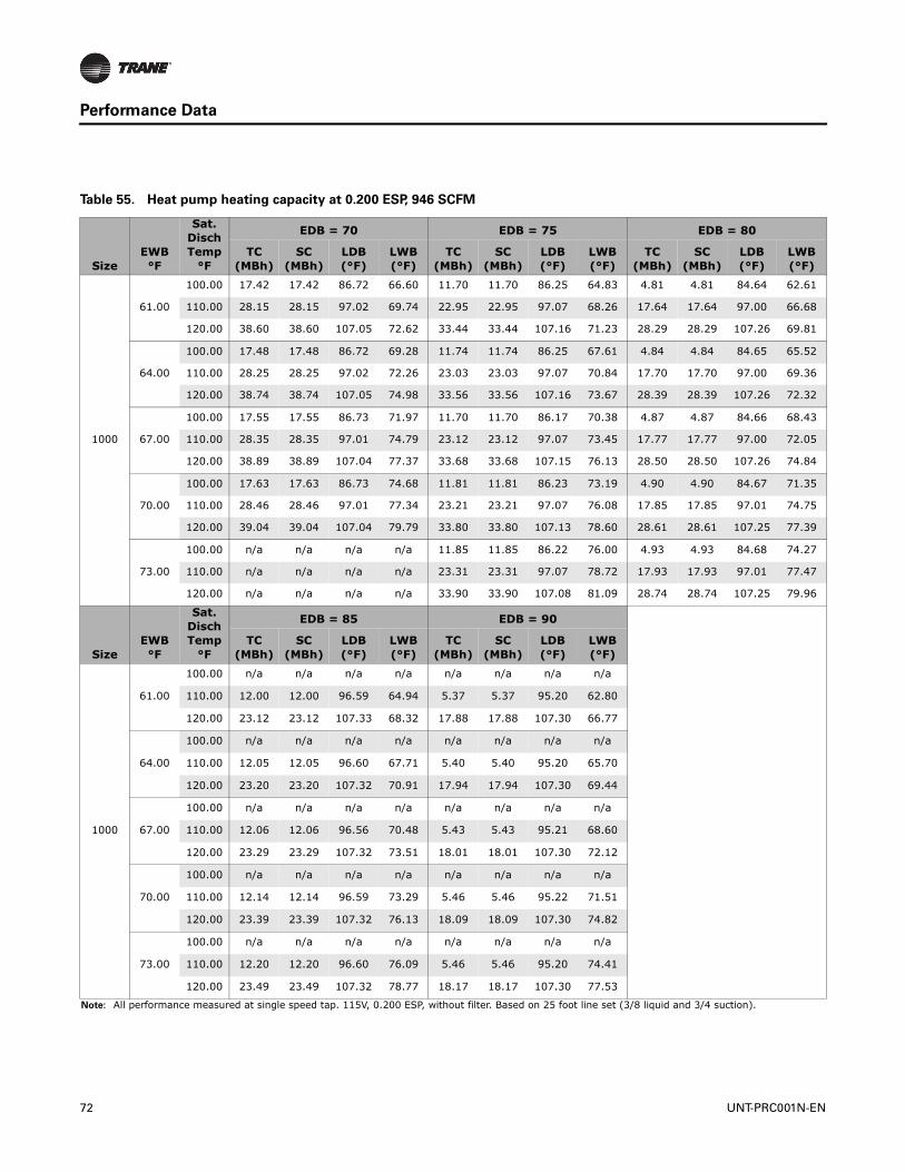
Performance Data
Table 55. Heat pump heating capacity at 0.200 ESP, 946 SCFM
SizeEWB°F
Sat. Disch Temp
°F
EDB = 70 EDB = 75 EDB = 80
TC (MBh)
SC (MBh)
LDB(°F)
LWB(°F)
TC (MBh)
SC (MBh)
LDB (°F)
LWB(°F)
TC (MBh)
SC (MBh)
LDB(°F)
LWB(°F)
1000
61.00
100.00 17.42 17.42 86.72 66.60 11.70 11.70 86.25 64.83 4.81 4.81 84.64 62.61
110.00 28.15 28.15 97.02 69.74 22.95 22.95 97.07 68.26 17.64 17.64 97.00 66.68
120.00 38.60 38.60 107.05 72.62 33.44 33.44 107.16 71.23 28.29 28.29 107.26 69.81
64.00
100.00 17.48 17.48 86.72 69.28 11.74 11.74 86.25 67.61 4.84 4.84 84.65 65.52
110.00 28.25 28.25 97.02 72.26 23.03 23.03 97.07 70.84 17.70 17.70 97.00 69.36
120.00 38.74 38.74 107.05 74.98 33.56 33.56 107.16 73.67 28.39 28.39 107.26 72.32
67.00
100.00 17.55 17.55 86.73 71.97 11.70 11.70 86.17 70.38 4.87 4.87 84.66 68.43
110.00 28.35 28.35 97.01 74.79 23.12 23.12 97.07 73.45 17.77 17.77 97.00 72.05
120.00 38.89 38.89 107.04 77.37 33.68 33.68 107.15 76.13 28.50 28.50 107.26 74.84
70.00
100.00 17.63 17.63 86.73 74.68 11.81 11.81 86.23 73.19 4.90 4.90 84.67 71.35
110.00 28.46 28.46 97.01 77.34 23.21 23.21 97.07 76.08 17.85 17.85 97.01 74.75
120.00 39.04 39.04 107.04 79.79 33.80 33.80 107.13 78.60 28.61 28.61 107.25 77.39
73.00
100.00 n/a n/a n/a n/a 11.85 11.85 86.22 76.00 4.93 4.93 84.68 74.27
110.00 n/a n/a n/a n/a 23.31 23.31 97.07 78.72 17.93 17.93 97.01 77.47
120.00 n/a n/a n/a n/a 33.90 33.90 107.08 81.09 28.74 28.74 107.25 79.96
SizeEWB°F
Sat. Disch Temp
°F
EDB = 85 EDB = 90
TC (MBh)
SC (MBh)
LDB(°F)
LWB(°F)
TC (MBh)
SC (MBh)
LDB (°F)
LWB(°F)
1000
61.00
100.00 n/a n/a n/a n/a n/a n/a n/a n/a
110.00 12.00 12.00 96.59 64.94 5.37 5.37 95.20 62.80
120.00 23.12 23.12 107.33 68.32 17.88 17.88 107.30 66.77
64.00
100.00 n/a n/a n/a n/a n/a n/a n/a n/a
110.00 12.05 12.05 96.60 67.71 5.40 5.40 95.20 65.70
120.00 23.20 23.20 107.32 70.91 17.94 17.94 107.30 69.44
67.00
100.00 n/a n/a n/a n/a n/a n/a n/a n/a
110.00 12.06 12.06 96.56 70.48 5.43 5.43 95.21 68.60
120.00 23.29 23.29 107.32 73.51 18.01 18.01 107.30 72.12
70.00
100.00 n/a n/a n/a n/a n/a n/a n/a n/a
110.00 12.14 12.14 96.59 73.29 5.46 5.46 95.22 71.51
120.00 23.39 23.39 107.32 76.13 18.09 18.09 107.30 74.82
73.00
100.00 n/a n/a n/a n/a n/a n/a n/a n/a
110.00 12.20 12.20 96.60 76.09 5.46 5.46 95.20 74.41
120.00 23.49 23.49 107.32 78.77 18.17 18.17 107.30 77.53
Note: All performance measured at single speed tap. 115V, 0.200 ESP, without filter. Based on 25 foot line set (3/8 liquid and 3/4 suction).
72 UNT-PRC001N-EN
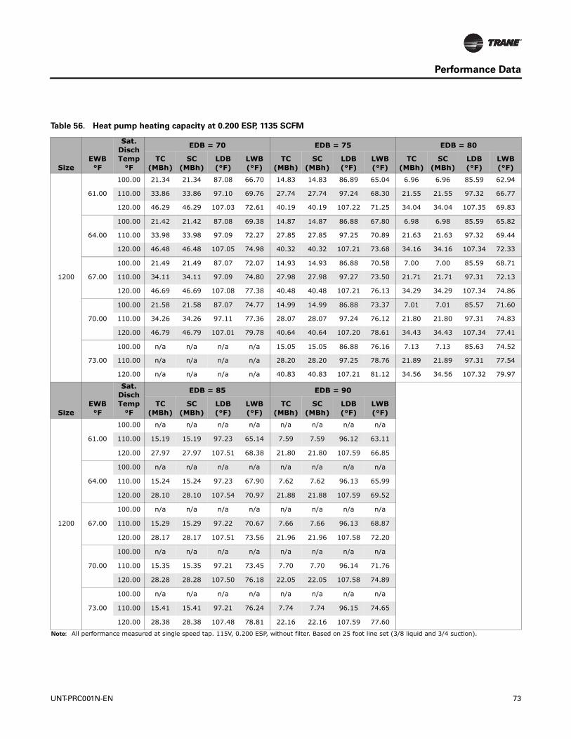
Performance Data
Table 56. Heat pump heating capacity at 0.200 ESP, 1135 SCFM
SizeEWB°F
Sat. Disch Temp
°F
EDB = 70 EDB = 75 EDB = 80
TC (MBh)
SC (MBh)
LDB(°F)
LWB(°F)
TC (MBh)
SC (MBh)
LDB (°F)
LWB(°F)
TC (MBh)
SC (MBh)
LDB(°F)
LWB(°F)
1200
61.00
100.00 21.34 21.34 87.08 66.70 14.83 14.83 86.89 65.04 6.96 6.96 85.59 62.94
110.00 33.86 33.86 97.10 69.76 27.74 27.74 97.24 68.30 21.55 21.55 97.32 66.77
120.00 46.29 46.29 107.03 72.61 40.19 40.19 107.22 71.25 34.04 34.04 107.35 69.83
64.00
100.00 21.42 21.42 87.08 69.38 14.87 14.87 86.88 67.80 6.98 6.98 85.59 65.82
110.00 33.98 33.98 97.09 72.27 27.85 27.85 97.25 70.89 21.63 21.63 97.32 69.44
120.00 46.48 46.48 107.05 74.98 40.32 40.32 107.21 73.68 34.16 34.16 107.34 72.33
67.00
100.00 21.49 21.49 87.07 72.07 14.93 14.93 86.88 70.58 7.00 7.00 85.59 68.71
110.00 34.11 34.11 97.09 74.80 27.98 27.98 97.27 73.50 21.71 21.71 97.31 72.13
120.00 46.69 46.69 107.08 77.38 40.48 40.48 107.21 76.13 34.29 34.29 107.34 74.86
70.00
100.00 21.58 21.58 87.07 74.77 14.99 14.99 86.88 73.37 7.01 7.01 85.57 71.60
110.00 34.26 34.26 97.11 77.36 28.07 28.07 97.24 76.12 21.80 21.80 97.31 74.83
120.00 46.79 46.79 107.01 79.78 40.64 40.64 107.20 78.61 34.43 34.43 107.34 77.41
73.00
100.00 n/a n/a n/a n/a 15.05 15.05 86.88 76.16 7.13 7.13 85.63 74.52
110.00 n/a n/a n/a n/a 28.20 28.20 97.25 78.76 21.89 21.89 97.31 77.54
120.00 n/a n/a n/a n/a 40.83 40.83 107.21 81.12 34.56 34.56 107.32 79.97
SizeEWB°F
Sat. Disch Temp
°F
EDB = 85 EDB = 90
TC (MBh)
SC (MBh)
LDB(°F)
LWB(°F)
TC (MBh)
SC (MBh)
LDB (°F)
LWB(°F)
1200
61.00
100.00 n/a n/a n/a n/a n/a n/a n/a n/a
110.00 15.19 15.19 97.23 65.14 7.59 7.59 96.12 63.11
120.00 27.97 27.97 107.51 68.38 21.80 21.80 107.59 66.85
64.00
100.00 n/a n/a n/a n/a n/a n/a n/a n/a
110.00 15.24 15.24 97.23 67.90 7.62 7.62 96.13 65.99
120.00 28.10 28.10 107.54 70.97 21.88 21.88 107.59 69.52
67.00
100.00 n/a n/a n/a n/a n/a n/a n/a n/a
110.00 15.29 15.29 97.22 70.67 7.66 7.66 96.13 68.87
120.00 28.17 28.17 107.51 73.56 21.96 21.96 107.58 72.20
70.00
100.00 n/a n/a n/a n/a n/a n/a n/a n/a
110.00 15.35 15.35 97.21 73.45 7.70 7.70 96.14 71.76
120.00 28.28 28.28 107.50 76.18 22.05 22.05 107.58 74.89
73.00
100.00 n/a n/a n/a n/a n/a n/a n/a n/a
110.00 15.41 15.41 97.21 76.24 7.74 7.74 96.15 74.65
120.00 28.38 28.38 107.48 78.81 22.16 22.16 107.59 77.60
Note: All performance measured at single speed tap. 115V, 0.200 ESP, without filter. Based on 25 foot line set (3/8 liquid and 3/4 suction).
UNT-PRC001N-EN 73

Controls
Why Trane Controls?
Trane offers a broad range of control packages from a field convertible end-device package, to a complete building automation system solution with BACnet® or LonTalk® controls.
The good news is Trane controls are factory-mounted, -wired, -tested and configured or programmed with Trane application expertise to provide comfort, efficiency, and reliability, as well as single-source warranty and service.WithTrane integrated controls, the installed costs are lower because the equipment has turn-key factory controls and every component of the system is optimized to fit with the controller.Trane installs not only the controller, but also the hardware that works intimately with the controller to allow the system to function properly (i.e., piping package, valves, dampers, actuators, etc.). When a product with Trane controls arrives on the jobsite, it is completely ready for quick installation.
Table 57. Tracer® controller input/output summary
ZN010 ZN510 ZN520 UC400-BBinary outputsSingle zone VAV •3-speed fan • • •2-position hydronic valve • • • •2-position mixing box damper • • •Electric heat • • • •Modulating mixed air damper • •Modulating hydronic valve • •Reheat (hydronic) • •Generic • • • •Binary inputsCondensate overflow detection • • • •Low temperature detection • • • •Occupancy • • • •Generic input • • • •Analog inputsZone temperature • • • •Setpoint • • • •Hydronic valve •Fan mode: auto, high, medium, low • • • •Entering water • • • •Discharge air • • • •Outside air • •Generic •Note: All functions are not available on all units. The generic input and output for ZN controls are for use with a Tracer® Summit
systems only.
Table 58. Tracer® controller function summary
Control functions ZN010 ZN510 ZN520 UC400-BEntering water temp. sampling (purge) • • • •Timed override • • • •Auto changeover • • • •Fan cycling • • •Warm-up • • • •Pre-cool • • • •Data sharing (master/slave) • •Random start • • • •Dehumidification •DX cooling •DX frost protection •Other FunctionsManual test • • • •Filter maintenance timer • • • •Setpoint limits • • • •
74 UNT-PRC001N-EN
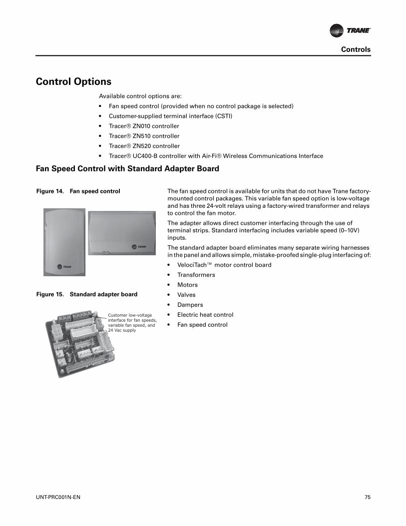
Controls
Control Options
Available control options are:
• Fan speed control (provided when no control package is selected)
• Customer-supplied terminal interface (CSTI)
• Tracer® ZN010 controller
• Tracer® ZN510 controller
• Tracer® ZN520 controller
• Tracer® UC400-B controller with Air-Fi® Wireless Communications Interface
Fan Speed Control with Standard Adapter Board
Figure 14. Fan speed control The fan speed control is available for units that do not have Trane factory-mounted control packages. This variable fan speed option is low-voltage and has three 24-volt relays using a factory-wired transformer and relays to control the fan motor.
The adapter allows direct customer interfacing through the use of terminal strips. Standard interfacing includes variable speed (0–10V) inputs.
The standard adapter board eliminates many separate wiring harnesses in the panel and allows simple, mistake-proofed single-plug interfacing of:
• VelociTach™ motor control board
• Transformers
• Motors
• Valves
• Dampers
• Electric heat control
• Fan speed control
Figure 15. Standard adapter board
Customer low-voltageinterface for fan speeds, variable fan speed, and 24 Vac supply
UNT-PRC001N-EN 75

Controls
Customer Supplied Terminal Interface (CSTI)
The CSTI is intended to be used with a field-supplied, low-voltage thermostat or controller. The control box contains a relay board which includes a line voltage to 24-volt transformer and disconnect switch (for non-electric heat units). All end devices are wired to a low-voltage terminal block and are run-tested, so the only a power connection and thermostat connection is needed to commission the unit. Changeover sensors and controls are provided whenever a change-over coil is selected. When N.O. valves are selected, inverting relays are provided for use with standard thermostats.
The CSTI adapter board provides all the hookups as the standard adapter board, but in addition, provides hookups for valve control (main and auxiliary coils), electric heat control, and damper control. Screw terminal blocks provide convenient access to fan controls and to end device control. In addition, a courtesy 10 VDC supply is provided for use with an external potentiometer or rheostat. The 10 VDC supply supports up to 10 mA draw.
Figure 16. CSTI adapter board and field connections
1. VSP 10V
2. VSP 0–10V
3. VSP DC COM
1. 24 Vac B (hot)
2. 24 Vac Y (gnd)
3. High
4. Medium
5. Low
6. V1Op/Cooling
7. V1Cl (not std)
8. Not used
9. Not used
10. V2Op/EH1St/Heating
11. V2Cl/EH2St (not std)
12. Damper Open
13. Dmp Cl (not std)
3 2 1 13 12 11 10 9 8 7 6 5 4 3 2 1 Customer low-voltageinterface for fan speeds, variable fan speed, and24 Vac supply, valve control,EH control, damper control,condensate overflow status
Valve(s), electric heat, andchangeover configurationswitches (factory-set)
76 UNT-PRC001N-EN

Controls
Tracer® Controllers
Tracer® ZN010 controller is a stand-alone microprocessor controller.
Tracer® ZN510 controller can be used as either a stand-alone or communicating microprocessor controller.
Tracer® ZN520 Controller
The Tracer® ZN520 controller is a factory-installed, -tested and -commissioned LonTalk® control designed to provide control of Trane products. Features include:
• Automatic fan-speed reset
• Automatic ventilation reset
• Active dehumidification
• Manual output test
• Filter maintenance
• Master slave
• Water valve override
• Freeze avoidance
• Interoperability
• Three generic I/O ports
The Tracer® ZN520 controller is designed to be used in the following applications:
• As part of a Tracer® SC or Tracer® Summit building automation system (BAS), the Tracer® ZN520 becomes an important part of the Tracer® control system.
• The Tracer® ZN520 can function as a completely stand-alone controller in situations where a BAS is not present.
• For situations when a non-Trane BAS is present, the Tracer® ZN520 can be used as an inter-operable unit controller.
Through building management of the HVAC system, optimizing energy consumption becomes possible at the room level. Each unit is capable of functioning independently of one another during occupied and unoccupied hours of the day. This allows the temperature setpoint and ventilation setting to be changed automatically based on usage.
Two Systems in One
In a Tracer® system environment, the Tracer® ZN520 is pre-designed to install quickly and easily into the system. Since the controller and the unit are factory tested and commissioned, the start-up time for the entire system is minimized. Trane becomes the single source of responsibility for the equipment, unit controls, and building automation system.
As a standalone controller, the Tracer® ZN520 is ideally suited for fix-on-fail replacement of units with old pneumatic controllers, or in situations where a BAS will be added at a later date. Once power is applied to the controller, it will automatically start up and run based upon the setpoint on the local zone sensor. An individual time clock can be added to the unit for local scheduling.
The Tracer® ZN520 is certified to the interoperable LONMARK® Space Comfort Controller profile. This allows the controller to be used with another vendor BAS and thereby still provide the high quality of factory installation and testing. In addition, the Tracer® ZN520 provides one of the most extensive interoperable data lists of any controller of its type in the industry.
UNT-PRC001N-EN 77
Controls
Tracer® UC400-B Controller
The Tracer® UC400-B single-zone VAV controller can be used in a stand-alone application or as part of a Tracer® control system.
In the stand-alone configuration, Tracer® UC400-B receives operation commands from the zone sensor and/or the auto changeover sensor (on auto changeover units).The entering water temperature is read from the auto changeover sensor and determines if the unit is capable of cooling or heating. The zone sensor module is capable of transmitting the following information to the controller:
• Timed override on/cancel request
• Zone setpoint
• Current zone temperature
• Fan mode selection (off-auto-high-med-low)
For optimal system performance, units can operate as part of a Tracer® SC building automation system. The controller is linked directly to the Tracer® SC via a twisted pair communication wire, requiring no additional interface device (i.e., a command unit). The Tracer® control system can monitor or override Tracer® UC400-B control points.This includes such points as temperature and output positions.
Tracer® Controller Features
The Tracer® family of controllers, ZN010, ZN510, ZN520, and UC400-B offer the combined advantages of simple and dependable operation with the latest Trane-designed controller. Standard control features include options normally available on more elaborate control systems. All control options are available factory-configured or can be field-configured using Rover or Tracer® TU service software. For more detailed information, refer to Trane installation manuals CNT-IOP-1 (for Tracer® ZN010 or ZN510), CNT-SVX04*-EN (for Tracer® ZN520), or BAS-SVX48*-EN (for Tracer® UC400-B).
Features Available on All Controllers
The following control functions are standard features on units with Tracer® ZN010, ZN510, ZN520, or Tracer® UC400-B.
Entering Water Temperature Sampling Function
A system that uses a two-way control valve option might not sense the correct entering water temperature during long periods when the control valve is closed. If the demand for heating or cooling does not exist for a long period, the entering water will eventually approach ambient temperature.
Using the entering water temperature sampling function, the controller provides accurate two-pipe system changeover-without sacrificing the benefits of two-way control valves. Also, it eliminates inefficient bleed or bypass lines that can allow unnecessary waterflow through the system.
This function periodically samples the entering water temperature by opening the hydronic valve. The valve opens for 20 seconds to allow the water temperature to stabilize.Then the controller reads the entering water temperature for up to three minutes to see if the correct water temperature is available for the selected operating mode.
The entering water temperature must be five degrees or more above the space temperature to allow hydronic heating and five degrees or more below the space temperature to allow hydronic cooling. If the correct water temperature for the operating mode is available, the unit begins normal heating or cooling operation. If the correct water temperature is not available, the controller closes the control valve and waits 60 minutes before attempting to sample the entering water temperature again.
78 UNT-PRC001N-EN
Controls
UNT-PRC001N-EN 79
A factory-mounted thermistor senses the entering water temperature on changeover cooling/ heating coil units. If the fan coil has a factory-mounted piping package, the sensor is strapped to the entering water pipe. If the fan coil does not have a piping package, the sensor is coiled in the end pocket for mounting on customer-supplied piping.This sensor must detect accurate water temperature for proper changeover.
Automatic Heat/Cool Mode Determination
The controller automatically determines whether heating or cooling is needed-based on space and system conditions. Using a proportional/integral (PI) control algorithm to maintain the space temperature at the active heating or cooling setpoint.The controller measures the space temperature and active setpoint temperature to determine the unit's heating or cooling capacity (zero to 100 percent).
Occupied/Unoccupied Operation
The occupancy input uses a binary switch (i.e., motion sensor, time clock, etc.) that allows the zone sensor to use its unoccupied internal setpoints.
Random Start
This feature randomly staggers multiple unit start-up to reduce electrical demand spikes.
Warm-up
The two-position fresh air damper option closes during the occupied mode when the space temperature is three degrees or more below the heating setpoint temperature.The damper remains closed during warm-up until the space temperature is within two degrees of the heating setpoint temperature.
Cool-down
The two-position fresh air damper option closes during the occupied mode when the space temperature is three degrees or more above the cooling setpoint temperature.The damper remains closed during cool-down until the space temperature is within two degrees of the cooling setpoint temperature.
Manual Output Test
This function may be initiated from the blue test push button on the controller or through the Rover or Tracer® TU service tool.This feature is used to manually exercise the outputs in a defined sequence.
The purpose of this test sequence is to verify output and end device operation.The manual output test function may also be used in the following situations:
• Reset latching diagnostics
• Verify output wiring and operation
• Force the water valve(s) open to balance the hydronic system during installation set-up or service.
Peer-to-Peer Communication (Tracer® ZN510, ZN520, and UC400-B)
Peer-to-peer communication allows multiple units in one space to share the same zone sensor and provide simultaneous heating and cooling.TheTracer® ZN510 or ZN520 controller can share information between units on the same communication link using a twisted pair wire in the field. Unit configuration must be modified with Rover service tool. On the Tracer® UC400-B, zone sensor data sharing can be accomplished by use of the BAS system controller.
A thermistor to sense fresh air is factory-mounted at the unit's fresh air opening for use in economizer applications or as a read-only point for Tracer® SC or Tracer® Summit. If the fresh air temperature is a read-only value, it will not impact the control algorithm. In an economizer application, a fresh air temperature signal must be provided either by this thermistor, Tracer® SC, or Tracer® Summit.

Controls
Additional Features
Single Zone VAV with Fully Modulating Fan Speed (Tracer® UC400-B)
The Tracer® UC400-B will minimize fan speed, and in turn energy usage, by only delivering the air flow needed.
Economizing Control (Tracer® ZN520)
With the controller configured for economizing control, it will calculate the required cooling capacity every ten seconds and modulate the damper option open to the calculated position. If the setpoint is not satisfied, the damper will continue to open until the setpoint condition has been met or the damper is 100 percent open. If this still does not satisfy the setpoint, the cooling valve option will begin to open and try to satisfy the load requirements. Once capacity exceeds the load requirements, the valve will begin to close until the setpoint has been reached or the damper reaches its minimum position, which is field-adjustable.This option uses a three-wire, floating point damper actuator.
A thermistor to sense discharge air is factory mounted near the discharge surface of the last coil for use in economizing and cascade temperature control.Tracer® SC or Tracer® Summit can also use this temperature value as a read-only point. Cascade temperature control uses both the zone and discharge air temperatures to more accurately calculate the required unit capacity.
Automatic Fan and Ventilation Reset
A two-speed fan control for the unit delivers the airflow output customized to support the cfm space needs.When less cfm is necessary to meet the load of the classroom (typically 75 to 80 percent of the time), the equipment operates on low speed. However, if the room temperature rises, the controller will switch to high speed, and the outside air damper will adjust to satisfy the space needs.This helps maintain the proper amount of ventilation air to the occupants independent of the fan speed. As part of the ventilation strategy, the controller will reposition the outside air damper to confirm the minimum outside air cfm is met at both operating conditions.
Filter Maintenance
Filter status for the controller is based on the cumulative run hours of the unit fan. The controller compares the amount of fan run time against an adjustable fan run hour (stored in the controller) to determine when maintenance is recommended for the unit. The run-hours value may be user edited as required (through Rover or Tracer® TU). The valid range for the fan run hours limit is 0 to 5000 hours with a default of 600 hours. Once the run hours limit has been exceeded, the
Figure 17. Cool mode nominal hydronic cooling control
70
80
Dis
charg
e te
mp
set
po
int
(°F)
No cooling load Design coolingload (demand)
Space sensible loadFa
n s
pee
d c
om
man
d (
%)
60
50
45
60
40
100
80
20
0
80 UNT-PRC001N-EN
Controls
controller generates a maintenance required diagnostic (unit will not shut-down). The user will be notified of this diagnostic through the building automation system or when a Trane service tool is communicating with the controller.
Active Dehumidification
On units with reheat coils, the controller can provide active dehumidification. This means that the relative humidity in the space can be kept below an adjustable setpoint independent of outdoor weather conditions. Indoor humidity levels are recommended by ASHRAE to be kept below 60 percent in order to minimize microbial growth and the life span of airborne illness causing germs.
Master Slave (Data Sharing)
The controller can send or receive data (setpoint, heat/cool mode, fan request, space temperature, etc.) to and from other controllers on the communication link with or without the existence of a building automation system. This applies to applications where multiple units might share one zone sensor for both stand-alone (with communication wiring between units) and a building automation system.
Water Valve Override
The controller can be commanded via the Rover service tool or Tracer® TU to open all hydronic valves 100 percent. This allows for the faster water balancing of each unit and the entire system when the command is sent globally to all controllers. A properly balanced system is essential for proper and efficient operation.
Hydronic Coil Freeze Protection (Freeze Avoidance)
Systems in cold climates need to take precautions to avoid hydronic coil freeze-up. The controller does this from three different aspects. Any of these methods of protections will result in the unit fan being disabled, the outside air damper being shut, and the hydronic valves being opened 100 percent.
The three methods of freeze avoidance include:
1. A binary freeze protection thermostat is mounted on the coil and will cause a latching diagnostic if the coil temperature falls below 35°F.
2. An analog discharge air sensor monitors the temperature of the air coming off of the coil and if the temperature falls below 40°F the outside air damper is closed, the fan is turned off and the valves are fully opened.
3. When in the unoccupied mode, the controller has an adjustable freeze avoidance setpoint. If the outside air temperature is below the setpoint, the unit will open the valves to allow water to flow through the coils.
Interoperability
Inter-operability allows the owner freedom to select multiple vendors, and multiple products. With this advantage, the owner can choose the best products, the best application, and the best service from a variety of suppliers to meet their evolving building control needs in a cost effective manner.
Generic Binary Input/Output
The three generic binary inputs/outputs are not part of the normal control, but are actually controlled through the Tracer® SC or Tracer® Summit system (when present) to issue commands to the controller to turn the generic inputs/outputs of add-on equipment (such as baseboard heating, exhaust fans, occupancy sensors, lighting, etc.) on and off. This binary port is not affected when other binary diagnostics interrupt unit operation.
UNT-PRC001N-EN 81
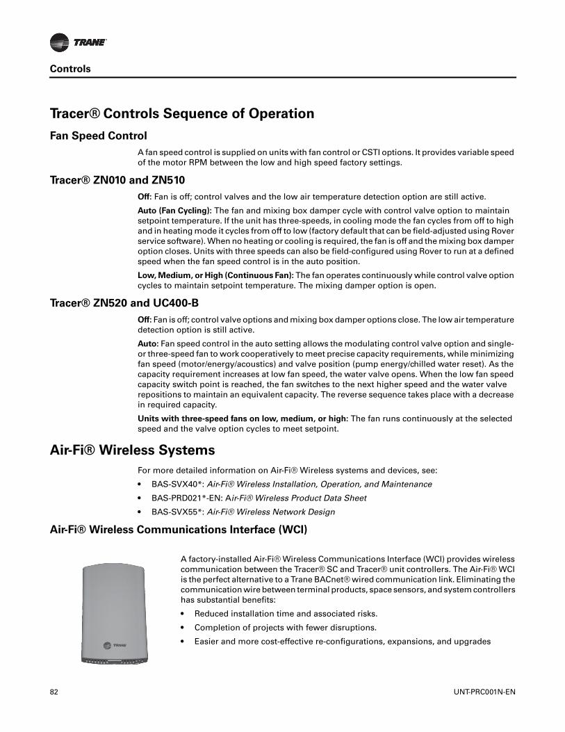
Controls
Tracer® Controls Sequence of Operation
Fan Speed Control
A fan speed control is supplied on units with fan control or CSTI options. It provides variable speed of the motor RPM between the low and high speed factory settings.
Tracer® ZN010 and ZN510
Off: Fan is off; control valves and the low air temperature detection option are still active.
Auto (Fan Cycling): The fan and mixing box damper cycle with control valve option to maintain setpoint temperature. If the unit has three-speeds, in cooling mode the fan cycles from off to high and in heating mode it cycles from off to low (factory default that can be field-adjusted using Rover service software). When no heating or cooling is required, the fan is off and the mixing box damper option closes. Units with three speeds can also be field-configured using Rover to run at a defined speed when the fan speed control is in the auto position.
Low, Medium, or High (Continuous Fan): The fan operates continuously while control valve option cycles to maintain setpoint temperature. The mixing damper option is open.
Tracer® ZN520 and UC400-B
Off: Fan is off; control valve options and mixing box damper options close. The low air temperature detection option is still active.
Auto: Fan speed control in the auto setting allows the modulating control valve option and single- or three-speed fan to work cooperatively to meet precise capacity requirements, while minimizing fan speed (motor/energy/acoustics) and valve position (pump energy/chilled water reset). As the capacity requirement increases at low fan speed, the water valve opens. When the low fan speed capacity switch point is reached, the fan switches to the next higher speed and the water valve repositions to maintain an equivalent capacity. The reverse sequence takes place with a decrease in required capacity.
Units with three-speed fans on low, medium, or high: The fan runs continuously at the selected speed and the valve option cycles to meet setpoint.
Air-Fi® Wireless Systems
For more detailed information on Air-Fi® Wireless systems and devices, see:
• BAS-SVX40*: Air-Fi® Wireless Installation, Operation, and Maintenance
• BAS-PRD021*-EN: Air-Fi® Wireless Product Data Sheet
• BAS-SVX55*: Air-Fi® Wireless Network Design
Air-Fi® Wireless Communications Interface (WCI)
A factory-installed Air-Fi® Wireless Communications Interface (WCI) provides wireless communication between the Tracer® SC and Tracer® unit controllers. The Air-Fi® WCI is the perfect alternative to a Trane BACnet® wired communication link. Eliminating the communication wire between terminal products, space sensors, and system controllers has substantial benefits:
• Reduced installation time and associated risks.
• Completion of projects with fewer disruptions.
• Easier and more cost-effective re-configurations, expansions, and upgrades
82 UNT-PRC001N-EN

Controls
Air-Fi® Wireless Communications Sensor (WCS)
Wireless Zone Sensor (WZS) Set
Communicates wirelessly to a Tracer® unit controller. A WCS is an alternative to a wired sensor when access and routing of communication cable are issues. A WCS allows flexible mounting and relocation.
A wireless zone sensor (WZS) set (sensor and receiver) communicates wirelessly to a Tracer® unit controller. A wireless zone sensor set is an alternative to a wired sensor when access and routing of communication cable are issues. The sensor allows flexible mounting and relocation.
Note: A wireless zone sensor set is not compatible with an Air-Fi® wireless system.
UNT-PRC001N-EN 83
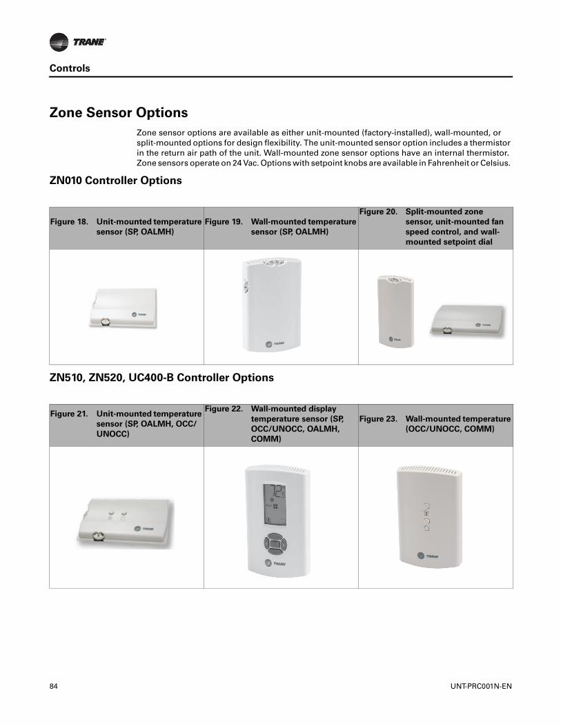
Controls
Zone Sensor Options
Zone sensor options are available as either unit-mounted (factory-installed), wall-mounted, or split-mounted options for design flexibility. The unit-mounted sensor option includes a thermistor in the return air path of the unit. Wall-mounted zone sensor options have an internal thermistor. Zone sensors operate on 24 Vac. Options with setpoint knobs are available in Fahrenheit or Celsius.
ZN010 Controller Options
ZN510, ZN520, UC400-B Controller Options
Figure 18. Unit-mounted temperature
sensor (SP, OALMH)
Figure 19. Wall-mounted temperature
sensor (SP, OALMH)
Figure 20. Split-mounted zone
sensor, unit-mounted fan
speed control, and wall-
mounted setpoint dial
Figure 21. Unit-mounted temperature
sensor (SP, OALMH, OCC/
UNOCC)
Figure 22. Wall-mounted display
temperature sensor (SP,
OCC/UNOCC, OALMH,
COMM)
Figure 23. Wall-mounted temperature
(OCC/UNOCC, COMM)
84 UNT-PRC001N-EN
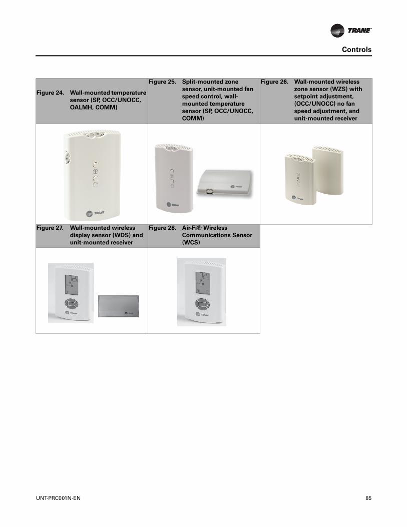
Controls
Figure 24. Wall-mounted temperature
sensor (SP, OCC/UNOCC,
OALMH, COMM)
Figure 25. Split-mounted zone
sensor, unit-mounted fan
speed control, wall-
mounted temperature
sensor (SP, OCC/UNOCC,
COMM)
Figure 26. Wall-mounted wireless
zone sensor (WZS) with
setpoint adjustment,
(OCC/UNOCC) no fan
speed adjustment, and
unit-mounted receiver
Figure 27. Wall-mounted wireless
display sensor (WDS) and
unit-mounted receiver
Figure 28. Air-Fi® Wireless
Communications Sensor
(WCS)
UNT-PRC001N-EN 85
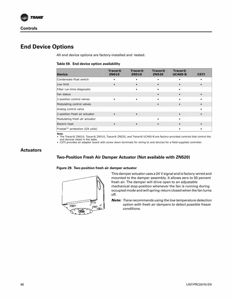
Controls
End Device Options
All end device options are factory-installed and -tested.
Actuators
Two-Position Fresh Air Damper Actuator (Not available with ZN520)
Table 59. End device option availability
Device Tracer®ZN010
Tracer® ZN510
Tracer® ZN520
Tracer® UC400-B CSTI
Condensate float switch • • • • •
Low limit • • • • •
Filter run-time diagnostic • • •
Fan status • • •
2-position control valves • • • • •
Modulating control valves • • •
Analog control valve •
2-position fresh air actuator • • • •
Modulating fresh air actuator • •
Electric heat • • • • •
Frostat™ protection (DX coils) • •
Note:
• The Tracer® ZN010, Tracer® ZN510, Tracer® ZN520, and Tracer® UC400-B are factory-provided controls that control the end devices listed in the table.
• CSTI provides an adapter board with screw down terminals for wiring to end devices for a field-supplied controller.
Figure 29. Two-position fresh air damper actuator
This damper actuator uses a 24 V signal and is factory-wired and mounted to the damper assembly. It allows zero to 50 percent fresh air. The damper will drive open to an adjustable mechanical stop-position whenever the fan is running during occupied mode and will spring-return closed when the fan turns off.
Note: Trane recommends using the low temperature detection option with fresh air dampers to detect possible freeze conditions.
86 UNT-PRC001N-EN
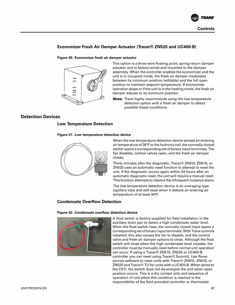
Controls
UNT-PRC001N-EN 87
Economizer Fresh Air Damper Actuator (Tracer® ZN520 and UC400-B)
Detection Devices
Low Temperature Detection
Condensate Overflow Detection
Figure 30. Economizer fresh air damper actuator
This option is a three-wire floating point, spring-return damper actuator and is factory-wired and mounted to the damper assembly. When the controller enables the economizer and the unit is in occupied mode, the fresh air damper modulates between its minimum position (editable) and the full open position to maintain setpoint temperature. If economizer operation stops or if the unit is in the heating mode, the fresh air damper adjusts to its minimum position.
Note: Trane highly recommends using the low temperature detection option with a fresh air damper to detect possible freeze conditions.
Figure 31. Low temperature detection device
When the low temperature detection device senses an entering air temperature of 36°F to the hydronic coil, the normally-closed switch opens a corresponding set of binary input terminals. The fan disables, control valves open, and the fresh air damper closes.
Thirty minutes after the diagnostic, Tracer® ZN010, ZN510, or ZN520 uses an automatic reset function to attempt to reset the unit. If the diagnostic occurs again within 24 hours after an automatic diagnostic reset, the unit will require a manual reset. This function attempts to resolve the infrequent nuisance alarm.
The low temperature detection device is an averaging type capillary tube and will reset when it detects an entering air temperature of at least 44°F.
Figure 32. Condensate overflow detection device
A float switch is factory-supplied for field installation in the auxiliary drain pan to detect a high condensate water level. When the float switch rises, the normally closed input opens a corresponding set of binary input terminals. With Trane controls installed, this also causes the fan to disable, and the control valve and fresh air damper options to close. Although the float switch will close when the high condensate level recedes, the controller must be manually reset before normal unit operation can occur. If using a Tracer® ZN510, ZN520 or UC400-B controller you can reset using Tracer® Summit. Use Rover service software to reset units with Tracer® ZN010, ZN510, or ZN520 and Tracer® TU for units with a UC400-B. When wired to the CSTI, the switch does not de-energize the unit when open position occurs. This is a dry contact only and sequence of operation of unit when this condition is reached is the responsibility of the field provided controller or thermostat.

Controls
Frostat™ Temperature Switch
Outside Air Sensor
The outside air sensor is field-mounted to sense the outside air temperature, primarily for use in economizer applications or as a status value when available for other applications.
Control Valves
Three-way valve options allow either full waterflow through the coil or diverted waterflow through the bypass.
Two-Position Control Valves
Two-position valves are capacitor discharge return. Capacitor discharge valves respond to a 24 V signal and will either fully open or close. These valves cannot be driven or actuated to a partially open or closed position. If the capacitor discharge return type control valve loses power, the valve returns to its de-energized position.
Modulating and 2-10 V Analog Control Valves
Modulating and 2-10 V Analog control valves offer an alternative for more precise capacity control by modulating or varying the water flow through the coil. Modulating valves respond to a 24 V signal from the controller, which determines the valve position by a control algorithm. Analog valves travel to the commanded position of the 2-10 V control signal. If the valve loses power, it remains in the position it was in when the power loss occurred.
Field-Supplied Valves
This option allows the controller to be factory-configured for a field-supplied valve, as well as a wire harnesses running from the control box to the piping side of the unit. When the field-supplied valve option is chosen, the control box is provided with low voltage components and wired back to a terminal strip (CSTI) or controller.
Note: Trane does not recommend wild coil applications.
Figure 33. Frostat™ temperature switch
When the Frostat switch senses a coil temperature of 39° F, the Frostat switch will open and the DX signal to the condenser will be interrupted. This turns off the compressor. The fan coil will continue to operate, allowing the coil to reach a temperature of 55°F. When the coil reaches 55°F, the Frostat will close allowing normal DX operation.
Units with either the control interface or any of the Tracer® controllers (Tracer® ZN010, ZN510, ZN520, or UC400-B) are available with chilled and/or hot water control valves for each coil configuration. Control valve options are available as:
• Analog (2-10 VDC)
• Modulating
• Two-position, normally-open (n.o.) or normally-closed (n.c.)
• Two- or three-way configurations
• With sweat connections
88 UNT-PRC001N-EN
Controls
Selecting the Correct Modulating Valve Size
The coefficient of flow is defined as the volume of water flow through a control valve in the fully open position with a 1 psig differential across the valve. It is calculated using the following formula:
Cv = Q/Square root ΔP where:
Cv = flow coefficient
Q = flow rate (gpm)
ΔP = pressure drop across the valve or coil (psig).
For good control, the valve Cv should be approximately equal to the Cv of the water coil.
Modulating Valve Selection Example
Assume a size 06 fan-coil is selected to operate at the following conditions:
Vertical Cabinet Fan Coil
Entering water temperature = 45°F
Leaving water temperature = 55°F
EAT conditions = 80/67
The coil is selected as a four-row coil.
Select the best modulating valve size for this unit.
1. Find the ΔP across the water coil. Refer to the AHRI performance table to determine the ΔP across the water coil (or use TOPSS™ selection program). The water pressure drop is found to be 7.0’ of water at a flow rate of 3.74 gpm. This converts to a pressure drop of 3.03 psig (1.0 feet of water = 0.4328 psig.)
2. Calculate the Cv of the water coil. Cv = GPM/Square root ΔP Cv = 3.74/Square root 3.03 Cv = 2.15 Therefore, the valve with the Cv of 2.4 should be selected since it has the Cv which is closest to the Cv of the water coil. The following tables illustrate possible valve selections at AHRI conditions for horizontal concealed units with a high static motor and vertical cabinet units with a free discharge motor.
Table 60. Valve availability
Digit 36 and
Digit 38 Cv
2-way,2-position,
N.C.
2-way,2-position,
N.O.
3-way,2-position,
N.C.
3-way,2-position,
N.O.2-way,
Modulating3-way
Modulating
2-way, Analog (2-10 VDC)
3-way, Analog (2-10 VDC)
A 1.4 X X X X
B 2.4 X X X X
C 3.4 X X
D 1.0 X X X X
E 2.7 X X X X
F 4.6 X X X X
UNT-PRC001N-EN 89

Electrical Data
MCA and MOP Calculations
Minimum Circuit Ampacity (MCA) and Maximum Overcurrent Protection
(MOP) Calculations for fan coils with electric heat (single-phase)
Heater Amps = (Heater kW x 1000)/Heater Voltage
Note: Use 120 V heater voltage for 115 V units. Use 240 V heater voltage for 230 V units.
MCA = 1.25 x (heater amps + all motor FLAs)
MOP = (2.25 x Largest Motor FLA) + Second Motor FLA + Heater Amps (If Applicable)
MOP is required in the branch circuit wiring for all fan coils with electric heat.
Select a standard fuse size or circuit breaker equal to the MOP. Use the next smaller standard size if the MOP does not equal a standard size. Ensure the selected fuse is larger than the MCA. Standard Fuse Sizes are: 15, 20, 25, 30, 35, 40, 45, 50, 60 amps
Fan coil electric heat MBh = (Heater kW) (3.413)
Minimum Circuit Ampacity (MCA) and Maximum Overcurrent Protection
(MOP) Calculations for fan coils (motors only, no electric heat)
MCA = (1.25) x [Largest Motor Amperes (FLA)] + Second Motor Amperes (FLA) (Size 10 and 12 only)
MOP = 15 Amps for all Fan Coils without Electric Heat (see previous Electrical Data for units with Electric Heat.)
Electric Heat
Table 61. Electric heat (kW)
Unit Size Unit Volt kW kW kW kW kW kW kW kW kW kW
02
115 1.0 1.5 2.0230 1.0 1.5 2.0277 1.0 1.5 2.0208 0.8 1.1 1.5 1.9
03
115 1.0 1.5 2.0 2.5230 1.0 1.5 2.0 2.5277 1.0 1.5 2.0 2.5208 0.8 1.1 1.5 1.9 2.3
04
115 2.0 2.5 3.0230 2.0 2.5 3.0277 2.0 2.5 3.0208 1.5 1.9 2.3 3.0
06
115 2.0 3.0230 2.0 3.0 4.0 5.0 6.0277 2.0 3.0 4.0 5.0 6.0208 1.5 2.3 3.0 3.8 4.5 5.3
08
115 2.0 3.0230 2.0 3.0 4.0 5.0 6.0 7.0277 2.0 3.0 4.0 5.0 6.0 7.0208 1.5 2.3 3.0 3.8 4.5 5.3 6.0
10
115 3.0230 3.0 4.0 5.0 6.0 7.0 8.0277 3.0 4.0 5.0 6.0 7.0 8.0208 2.3 3.0 3.8 4.5 5.3 6.0
12
115 3.0230 3.0 4.0 5.0 6.0 7.0 8.0277 3.0 4.0 5.0 6.0 7.0 8.0208 2.3 3.0 3.8 4.5 5.3 6.0
90 UNT-PRC001N-EN
Electrical Data
Motors
Table 62. Electric heat (kW), low vertical units
Unit Size Unit Voltage kW kW kW03 115 1.0 1.5 2.004 115 1.0 1.5 2.006 115 1.0 1.5 2.0
Note: Low vertical units are only available with electric heat in combination with the two-row cooling coil.
Table 63. Free discharge and high static electrically commutated motors (ECMs) programmed to standard ECM mode
Unit Size
115 Volt 208–230 Volt 277 VoltFLA HP FLA HP FLA HP
1 2 1 2 1 2 1 2 1 2 1 202 3.10 0.22 1.80 0.22 1.60 0.2403 3.10 0.22 1.80 0.22 1.60 0.2404 3.10 0.22 1.80 0.22 1.60 0.2406 3.10 0.22 1.80 0.22 1.60 0.2408 3.10 0.22 1.80 0.22 1.60 0.2410 3.10 3.10 0.22 0.22 1.80 1.80 0.22 0.22 1.60 1.60 0.24 0.2412 3.10 3.10 0.22 0.22 1.80 1.80 0.22 0.22 1.60 1.60 0.24 0.24
Table 64. Free discharge electrically commutated motors (ECMs) programmed to reduced FLA mode
Unit Size
115 Volt 208–230 Volt 277 VoltFLA HP FLA HP FLA HP
1 2 1 2 1 2 1 2 1 2 1 202 0.60 0.22 0.4 0.22 0.30 0.2403 0.60 0.22 0.4 0.22 0.30 0.2404 0.80 0.22 0.6 0.22 0.40 0.2406 1.10 0.22 0.8 0.22 0.60 0.2408 1.60 0.22 1.1 0.22 0.80 0.2410 0.70 1.20 0.22 0.22 0.5 0.80 0.22 0.22 0.40 0.60 0.24 0.2412 0.70 1.30 0.22 0.22 0.5 0.90 0.22 0.22 0.40 0.70 0.24 0.24
Table 65. High static electrically commutated motors (ECMs) programmed to reduced FLA mode
Unit Size
115 Volt 208–230 Volt 277 VoltFLA HP FLA HP FLA HP
1 2 1 2 1 2 1 2 1 2 1 202 1.3 0.22 0.9 0.22 0.7 0.2403 1.3 0.22 0.9 0.22 0.7 0.2404 1.7 0.22 1.2 0.22 0.9 0.2406 2.3 0.22 1.6 0.22 1.2 0.2408 3.1 0.22 1.8 0.22 1.5 0.2410 1.4 2 0.22 0.22 1 1.4 0.22 0.22 0.7 1.1 0.24 0.2412 1.5 2.8 0.22 0.22 1.1 1.8 0.22 0.22 0.8 1.4 0.24 0.24
UNT-PRC001N-EN 91

Electrical Data
RPM
Table 66. Low vertical free discharge electrically commutated motors (ECMs)
Unit Size115 Volt RPM
FLA HP H M L03 3.1 0.22 1090 770 56004 3.1 0.22 1090 750 56006 3.1 0.22 1115 760 560
Note: Actual rpm will vary with application and configuration.
Table 67. Lowboy vertical free discharge electrically commutated motors (ECMs) programmed with reduced FLA mode
Unit Size115 Volt RPM
FLA HP H M L03 0.5 0.22 1090 770 56004 0.8 0.22 1090 750 56006 1 0.22 1115 760 560
Note: Actual rpm will vary with application and configuration.
Table 68. Unit RPM
Unit Size
Free Discharge—Units with 2-Row Coils Free Discharge—Units with 3- and 4-Row CoilsH M L H M L
02 980 840 655 980 840 65503 980 780 580 1080 800 60004 1050 780 580 1080 800 60006 1030 780 580 1080 800 60008 1080 800 600 1080 800 600
101050 780 580 1080 800 6001030 780 580 1080 800 600
121050 780 580 1080 800 6001080 800 600 1080 800 600
Unit Size
High Static—Units with 2-Row Coils High Static—Units with 3- and 4-Row CoilsH M L H M L
02 1480 1110 865 1480 1110 86503 1400 1175 860 1500 1355 111004 1475 1315 1070 1580 1375 124006 1400 1070 855 1475 1285 97508 1475 1285 975 1475 1285 975
101475 1315 1070 1580 1375 12401400 1070 855 1475 1285 975
121475 1315 1070 1580 1375 12401475 1285 975 1475 1285 975
Note: Actual rpm will vary with application and configuration.
92 UNT-PRC001N-EN

Electrical Data
Table 69. RPM for DX/HP units
Unit Size
Free Discharge - Units with 2-Row Coils Free Discharge-Units with 3- and 4-Row Coils
H M L H M L 02 980 840 655 980 840 655
03 980 780 580 1080 800 600
04 1050 780 580 1080 800 600
06 1030 780 580 1080 800 600
06 DX/HP n/a n/a n/a 1080 n/a n/a
08 1080 800 600 1080 800 600
08 DX/HP n/a n/a n/a 1080 n/a n/a
10 1050 780 580 1080 800 600
1030 780 580 1080 800 600
10 DX/HP n/a n/a n/a 1080 n/a n/a
10 DX/HP n/a n/a n/a 1080 n/a n/a
12 1050 780 580 1080 800 600
1080 800 600 1080 800 600
12 DX/HP n/a n/a n/a 1080 n/a n/a
12 DX/HP n/a n/a n/a 1080 n/a n/a
Unit Size
High Static - Units with 2-Row Coils High Static - Units with 3- and 4-Row Coils
H M L H M L 02 1480 1110 865 1480 1110 865
03 1400 1175 860 1500 1255 1110
04 1475 1315 1070 580 1375 1240
06 1400 1070 855 1478 1285 975
06 DX/HP n/a n/a n/a 1475 n/a n/a
08 1475 1285 975 1580 1285 975
08 DX/HP n/a n/a n/a 1580 n/a n/a
10 1475 1315 1070 1580 1375 1240
1400 1070 855 1475 1285 975
10 DX/HP n/a n/a n/a 1580 n/a n/a
10 DX/HP n/a n/a n/a 1475 n/a n/a
12 1475 1315 1070 1580 1375 1240
1475 1285 975 1475 1285 975
12 DX/HP n/a n/a n/a 1580 n/a n/a
12 DX/HP n/a n/a n/a 1475 n/a n/a
UNT-PRC001N-EN 93

Dimensions and Weights
Service Clearances
Service access is available from the front on vertical units and from the bottom on horizontal units. Cabinet and recessed units have removable front or bottom panels to allow access into the unit.
Figure 34. Recommended service clearances for vertical units
Model A Vertical ConcealedModel K Low Vertical ConcealedModel H Vertical Recessed 36 in.
8.5 in.both sides
12 in.both sides
24 in.
3 in.Model B Vertical CabinetModel L Low Vertical Cabinet
Figure 35. Recommended service clearances for horizontal units
Model D Horizontal CabinetModel C Horizontal ConcealedModel E Horizontal Recessed
8.5 in.both sides
12 in.both sides
28 in.
24 inchesfront discharge
28 in.
94 UNT-PRC001N-EN

Dimensions and Weights
Model A Vertical Concealed
Figure 36. Model A Vertical Concealed
Top View
Powerwiring
bottomonly
1 3/32 in. KO7/8 in. KO
1 3/4 in. 1 3/4 in.
3 3/8 in.
5 5/16 in.Top outletduct collar
D1 in. 1 in.
Auxiliarycontrol box opt.6 1/4 in.
Controlbox
1 3/8 in.2 7/8 in.
C
Front ViewRH Piping
5/8 in. bolt hole
7/8 in. KOcontrol wiring
Optional disconnect switch
Auxiliarycontrol box
optional
5 1/4 in.
6 7/8 in.
Controlbox
6 15/16 in.
A
E 6 7/16 in.
9/16 in.
4 1/2 in. 7 in.
15 1/2 in.
26 1/4 in.
1 5/8 in.
1 in. duct collar
(4) 5/8 in. dia keyslothanger holes
3/4 in.
Front inletopen
4 7/16 in.
3/4 in.
1 3/4 in. 1 3/4 in.SideView 10 1/16 in.
Airflow
Secondary drain connection for 3/8 in. ID tube
Main drain connectionfor 7/8 in. OD coppertube and clamp
5 7/16 in.
1 9/16 in.
10 1/16 in.
Front ViewLH Piping
Coil connections
1 1/8 in.Auxiliarydrain pan
Power wiring 7/8 in.or 1 3/32 in. KOs
AuxBox
Control Box
Filters
UNT-PRC001N-EN 95

Dimensions and Weights
Table 70. Model A Vertical concealed unit dimensions (inches)
Unit Size 200-300 400 600 800 1000-1200No. Fans 1 1 2 2 3
No. Motors 1 1 1 1 2A 32 11/16 37 11/16 47 3/16 55 11/16 74 11/16B 21 5/16 26 5/16 35 13/16 44 5/16 63 5/16C 22 13/16 27 13/16 37 5/16 45 13/16 64 13/16D 17 5/16 22 5/16 2’-7 13/16 40 5/16 59 5/16E 19 5/16 24 5/16 33 13/16 42 5/16 61 5/16
Notes: Coil connections are always on the drain pan side and opposite the control box. Coil connections are 5/8-in. O.D. sweat. Refer to the Coil Connections section in the Dimension and Weights chapter for location. All duct collar dimensions are to the outside of the collar. Refer to the Fresh air opening section in the Dimensions and Weights chapter for more information.
96 UNT-PRC001N-EN
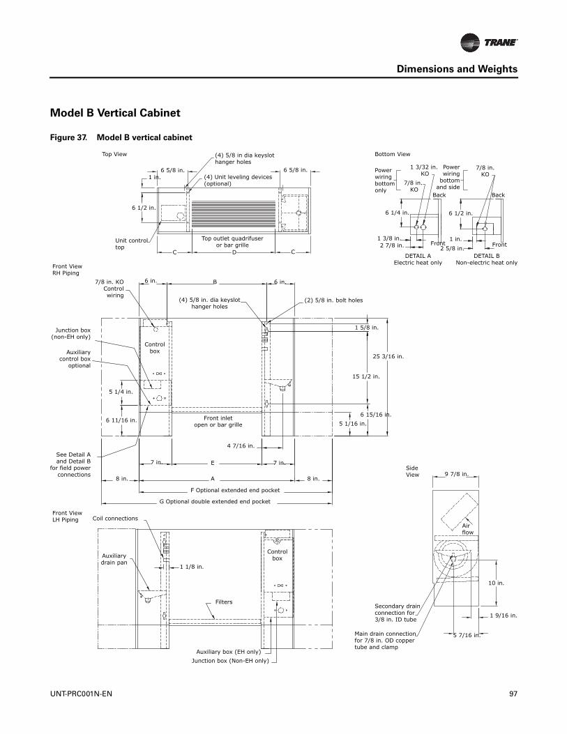
Dimensions and Weights
Model B Vertical Cabinet
Figure 37. Model B vertical cabinet
Top View (4) 5/8 in dia keyslothanger holes
(4) Unit leveling devices(optional)
6 5/8 in.1 in.
6 5/8 in.
6 1/2 in.
Unit controltop
Top outlet quadrifuseror bar grille
C D C
(2) 5/8 in. bolt holes
6 in. 6 in.B
(4) 5/8 in. dia keyslothanger holes
7/8 in. KOControlwiring
Front ViewRH Piping
Auxiliarycontrol box
optional
5 1/4 in.
6 11/16 in. Front inletopen or bar grille
4 7/16 in.
7 in. E
A
7 in.
8 in.
Controlbox
F Optional extended end pocket
Front ViewLH Piping Coil connections
Auxiliarydrain pan
1 1/8 in.
Filters
Controlbox
1 5/8 in.
25 3/16 in.
15 1/2 in.
6 15/16 in.5 1/16 in.
Secondary drain connection for 3/8 in. ID tube
Main drain connectionfor 7/8 in. OD coppertube and clamp
5 7/16 in.
1 9/16 in.
10 in.
Airflow
9 7/8 in.SideView
Powerwiringbottom only
2 7/8 in.1 3/8 in.
7/8 in. KO
1 3/32 in. KO
Bottom View
Powerwiring
bottomand side
7/8 in.KO
6 1/4 in. 6 1/2 in.
Back
Front1 in.
2 5/8 in.Front
Back
DETAIL AElectric heat only
DETAIL BNon-electric heat only
G Optional double extended end pocket
8 in.
See Detail Aand Detail B
for field powerconnections
Junction box(non-EH only)
Auxiliary box (EH only)Junction box (Non-EH only)
UNT-PRC001N-EN 97

Dimensions and Weights
Table 71. Model B Vertical cabinet unit dimensions (inches)
Unit Size 200-300 400 600 800 1000-1200No. Fans 1 1 2 2 3
No. Motors 1 1 1 1 2A 33 5/16 38 5/16 47 13/16 56 5/16 75 5/16B 21 5/16 26 5/16 35 13/16 44 5/16 63 5/16C 7 5/8 7 1/8 8 7/8 7 1/8 7 5/8D 18 24 30 42 60E 19 5/16 24 5/16 33 13/16 42 5/16 61 5/16F 41 5/16 46 5/16 55 13/16 64 5/16 83 5/16G 49 5/16 54 5/16 63 13/16 72 5/16 n/a
Notes: Coil connections are always on the drain pan side and opposite the control box. Coil connections are 5/8-in. O.D. sweat. Refer to the Coil Connections section in the Dimension and Weights chapter for location. All duct collar dimensions are to the outside of the collar. Refer to the Fresh air opening section in the Dimensions and Weights chapter for more information.
98 UNT-PRC001N-EN
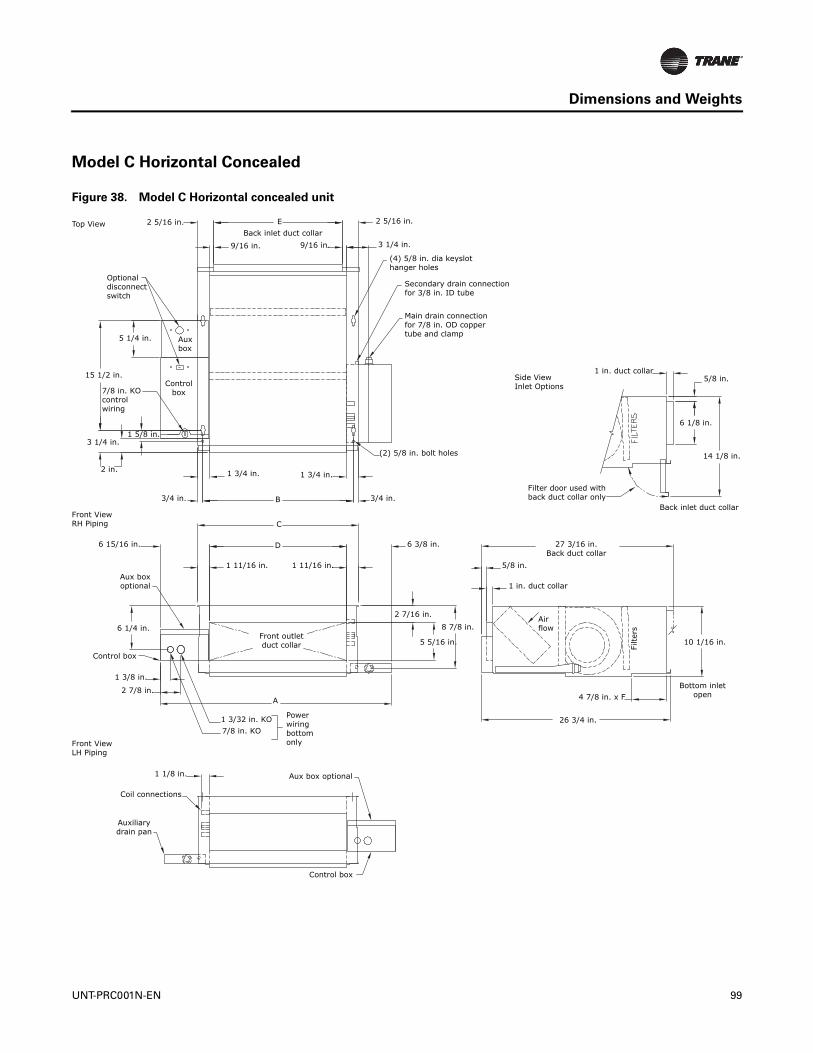
Dimensions and Weights
Model C Horizontal Concealed
Figure 38. Model C Horizontal concealed unit
Top View 2 5/16 in. EBack inlet duct collar
9/16 in. 9/16 in.
Optionaldisconnect switch
Auxbox
5 1/4 in.
15 1/2 in.
7/8 in. KOcontrol wiring
1 5/8 in.3 1/4 in.
2 in. 1 3/4 in. 1 3/4 in.
2 5/16 in.
3 1/4 in.
(4) 5/8 in. dia keyslothanger holes
Secondary drain connectionfor 3/8 in. ID tube
Main drain connectionfor 7/8 in. OD coppertube and clamp
Controlbox
(2) 5/8 in. bolt holes
3/4 in. 3/4 in.
Front ViewRH Piping
6 15/16 in.
B
C
D
1 11/16 in. 1 11/16 in.
6 3/8 in.
Aux boxoptional
6 1/4 in.
Control box
1 3/8 in.
2 7/8 in.
1 3/32 in. KO7/8 in. KO
Powerwiringbottomonly
A
2 7/16 in.8 7/8 in.
5 5/16 in.Front outletduct collar
Front ViewLH Piping
1 1/8 in. Aux box optional
Control box
Auxiliarydrain pan
Coil connections
26 3/4 in.
4 7/8 in. x FBottom inlet
open
10 1/16 in.Fi
lters
Airflow
1 in. duct collar
27 3/16 in.Back duct collar
5/8 in.
Filter door used withback duct collar only
Back inlet duct collar
14 1/8 in.
6 1/8 in.
5/8 in.1 in. duct collar
Side ViewInlet Options
UNT-PRC001N-EN 99
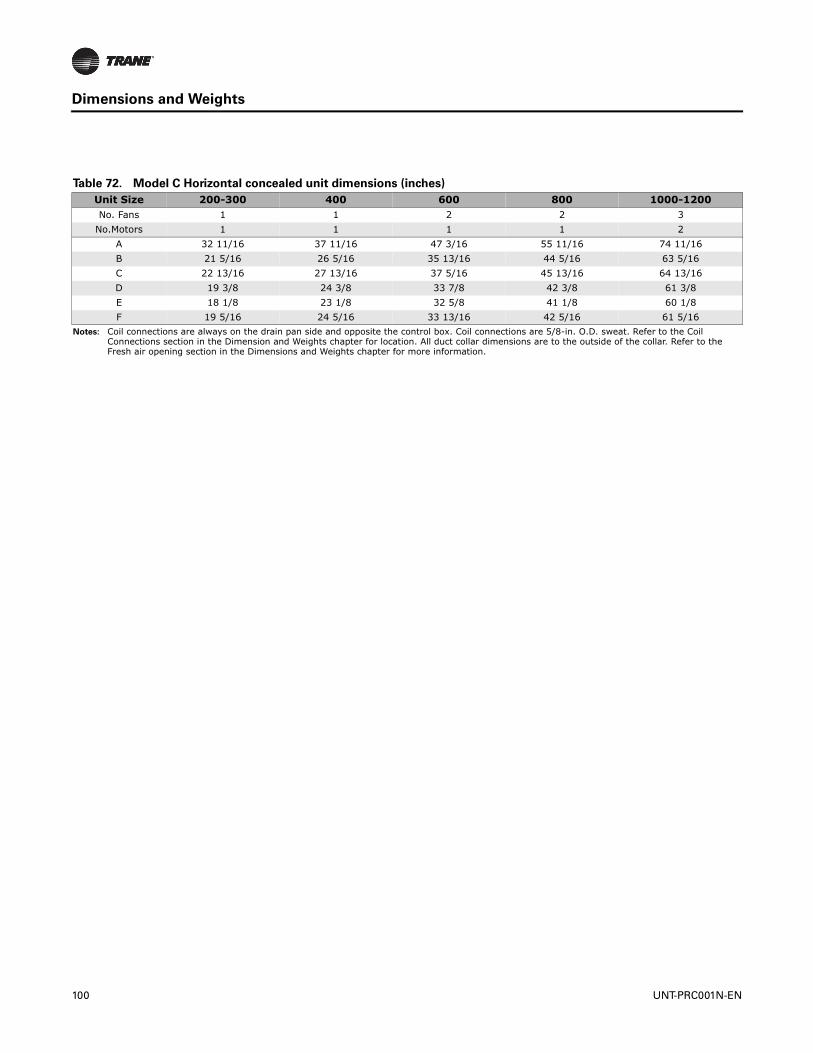
Dimensions and Weights
Table 72. Model C Horizontal concealed unit dimensions (inches)
Unit Size 200-300 400 600 800 1000-1200No. Fans 1 1 2 2 3
No.Motors 1 1 1 1 2A 32 11/16 37 11/16 47 3/16 55 11/16 74 11/16B 21 5/16 26 5/16 35 13/16 44 5/16 63 5/16C 22 13/16 27 13/16 37 5/16 45 13/16 64 13/16D 19 3/8 24 3/8 33 7/8 42 3/8 61 3/8E 18 1/8 23 1/8 32 5/8 41 1/8 60 1/8F 19 5/16 24 5/16 33 13/16 42 5/16 61 5/16
Notes: Coil connections are always on the drain pan side and opposite the control box. Coil connections are 5/8-in. O.D. sweat. Refer to the Coil Connections section in the Dimension and Weights chapter for location. All duct collar dimensions are to the outside of the collar. Refer to the Fresh air opening section in the Dimensions and Weights chapter for more information.
100 UNT-PRC001N-EN

Dimensions and Weights
Model D Horizontal Cabinet
Figure 39. Model D Horizontal Cabinet
Top View
EBack inlet duct collar
8 in. 8 in.
JBack and bottom
inlet louvers
Optional disconnect
switch
Auxbox
Controlbox
(4) 5/8 in. dia keyslothanger holes
Secondary drainconnection for 3/8 in. ID tube
Main drain connectionfor 7/8 in. OD coppertube and clamp
15 1/2 in.7/8 in.
KO control wiring
(2) 5/8 in.bolt holes
Front ViewRH Piping
Unit controlfront
Front outletduct collar (optional)
H
B
G
6 in.
G
6 in.
3 3/4 in.
13 3/4 in.
3 3/4 in.1 5/8 in.
Front outletquadrifuser or bar grille
C D CA 8 in.
F Optional extended end pocket
2 7/8 in.1 3/8 in.
Aux box opt.
6 1/4 in.
Control box1 3/32 in. KO
7/8 in. KO
Powerwiringbottomonly
Front ViewLH Piping
Coil connections
1 1/8 in.Aux Boxoptional
Control boxAuxiliarydrain pan
Filters
2 1/4 in.Bottom inlet
louvers 7 5/16 in.
1 in. ductcollar
Side ViewInlet and outlet
options 1 3/4 in.
7 in.
Filte
rs
Back inletduct collar1 in. front outlet
duct collar27 13/16 in.
26 13/16 in.
1 3/4 in.
7 in.10 5/16 in.
Back inletlouvers
Bottom access panel - all units
90° to fully open
8 7/8 in.
3 5/8 in.
4 in.
Air flow
Filte
rs
UNT-PRC001N-EN 101
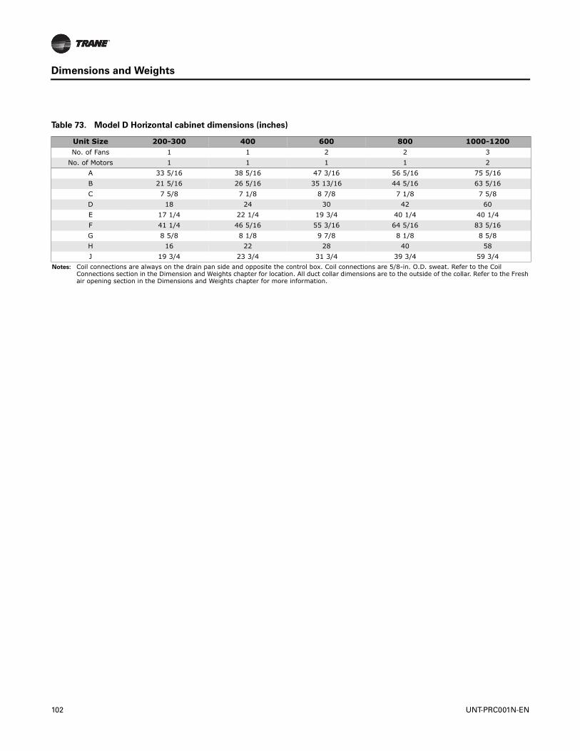
Dimensions and Weights
Table 73. Model D Horizontal cabinet dimensions (inches)
Unit Size 200-300 400 600 800 1000-1200No. of Fans 1 1 2 2 3
No. of Motors 1 1 1 1 2A 33 5/16 38 5/16 47 3/16 56 5/16 75 5/16B 21 5/16 26 5/16 35 13/16 44 5/16 63 5/16C 7 5/8 7 1/8 8 7/8 7 1/8 7 5/8D 18 24 30 42 60E 17 1/4 22 1/4 19 3/4 40 1/4 40 1/4F 41 1/4 46 5/16 55 3/16 64 5/16 83 5/16G 8 5/8 8 1/8 9 7/8 8 1/8 8 5/8H 16 22 28 40 58J 19 3/4 23 3/4 31 3/4 39 3/4 59 3/4
Notes: Coil connections are always on the drain pan side and opposite the control box. Coil connections are 5/8-in. O.D. sweat. Refer to the Coil Connections section in the Dimension and Weights chapter for location. All duct collar dimensions are to the outside of the collar. Refer to the Fresh air opening section in the Dimensions and Weights chapter for more information.
102 UNT-PRC001N-EN
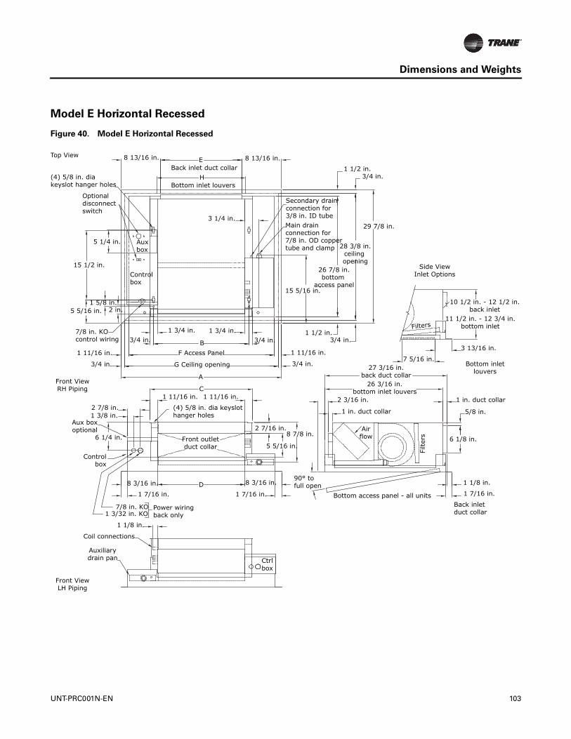
Dimensions and Weights
Model E Horizontal Recessed
Figure 40. Model E Horizontal Recessed
Top View 8 13/16 in.
(4) 5/8 in. diakeyslot hanger holes
Optionaldisconnectswitch
5 1/4 in. Auxbox
3 1/4 in.
15 1/2 in.Controlbox
EBack inlet duct collar
HBottom inlet louvers
8 13/16 in.1 1/2 in.
3/4 in.
29 7/8 in.
1 5/8 in.5 5/16 in. 2 in.
7/8 in. KOcontrol wiring
1 11/16 in.
3/4 in.
3/4 in.1 3/4 in. 1 3/4 in.
3/4 in.BF Access Panel
G Ceiling opening
Secondary drainconnection for3/8 in. ID tubeMain drainconnection for 7/8 in. OD coppertube and clamp 28 3/8 in.
ceiling opening
26 7/8 in.bottom
access panel
Side ViewInlet Options
15 5/16 in.
Front ViewRH Piping
1 1/2 in.3/4 in.
1 11/16 in.
3/4 in.
2 7/8 in.1 3/8 in.
Aux boxoptional
6 1/4 in.
Controlbox
8 3/16 in.
1 7/16 in.
7/8 in. KO1 3/32 in. KO
Power wiringback only
1 1/8 in.
Coil connections
Auxiliarydrain pan
Front ViewLH Piping
Ctrlbox
A
C1 11/16 in.1 11/16 in.
(4) 5/8 in. dia keyslothanger holes
2 7/16 in.8 7/8 in.
5 5/16 in.
8 3/16 in.
1 7/16 in. Bottom access panel - all units
90° to full open
Back inletduct collar
1 7/16 in.
1 1/8 in.D
Front outletduct collar
1 in. duct collar
27 3/16 in.back duct collar
26 3/16 in.bottom inlet louvers
2 3/16 in.
1 in. duct collar 5/8 in.
6 1/8 in.
Filte
rsAirflow
7 5/16 in.Bottom inlet
louvers
3 13/16 in.
11 1/2 in. - 12 3/4 in.bottom inlet
10 1/2 in. - 12 1/2 in.back inlet
Filters
UNT-PRC001N-EN 103

Dimensions and Weights
Table 74. Model E Horizontal recessed unit dimensions (inches)
Unit Size 200-300 400 600 800 1000-1200No. Fans 1 1 2 2 3
No. Motors 1 1 1 1 2A 35 13/16 40 13/16 50 5/16 58 13/16 77 13/16B 21 5/16 26 5/16 35 13/16 44 5/16 63 5/16C 22 13/16 27 13/16 37 5/16 45 13/16 64 13/16D 19 3/8 24 3/8 33 7/8 42 3/8 61 3/8E 18 1/8 23 1/8 32 5/8 41 1/8 60 1/8F 32 7/16 37 7/16 46 15/16 55 7/16 74 7/16G 34 5/16 39 5/16 48 13/16 57 5/16 76 5/16H 19 3/4 23 3/4 31 3/4 39 3/4 59 3/4
Notes: Coil connections are always on the drain pan side and opposite the control box. Coil connections are 5/8-in. O.D. sweat. Refer to the Coil Connections section in the Dimension and Weights chapter for location. All duct collar dimensions are to the outside of the collar. Refer to the Fresh air opening section in the Dimensions and Weights chapter for more information.
104 UNT-PRC001N-EN
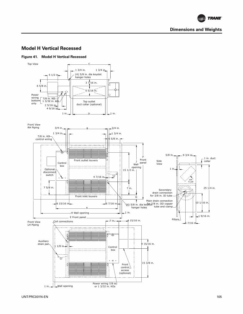
Dimensions and Weights
Model H Vertical Recessed
Figure 41. Model H Vertical Recessed
Top View
Front ViewRH Piping
Front ViewLH Piping
Side View
5 1/2 in.
C
1 3/4 in. 1 3/4 in.
(4) 5/8 in. dia keyslothanger holes
3 7/16 in.
5 5/16 in.
Top outletduct collar (optional)
6 5/8 in.
Powerwiringbottom only
7/8 in. KO1 3/32 in. KO
2 5/16 in.4 9/16 in.
1 in. D 1 in.
3/4 in.
1 3/4 in.
3/4 in.
1 3/4 in.
6 5/8 in.7/8 in. KO
control wiring
Front outlet louversControl
boxOptional
disconnectswitch
7 5/8 in.
4 7/16 in.
6 15/16 in.
Front inlet louvers
6 7/16 in.
A
H Wall opening
FFrontpanelJ
Wall opening
15 1/2 in.
7 in.
G
B
(4) 5/8 in. dia keyslothanger holes
1 in.
4 15/16 in.7 in.E Front panel
Coil connections
Auxiliarydrain pan
1 1/8 in.
1 in. Wall openingPower wiring 7/8 in.
or 1 3/32 in. KOs
Frontcontrolaccess
(optional)
15 3/8 in.
4 15/16 in.Control
box
5/8 in.1 in. duct collar
25 1/4 in.
10 1/16 in.
1 9/16 in.
5 7/16 in.Filters
Main drain connectionfor 7/8 in. OD copper
tube and clamp
Secondary drain connection
for 3/8 in. ID tube
9 3/4 in.
1 in.
UNT-PRC001N-EN 105
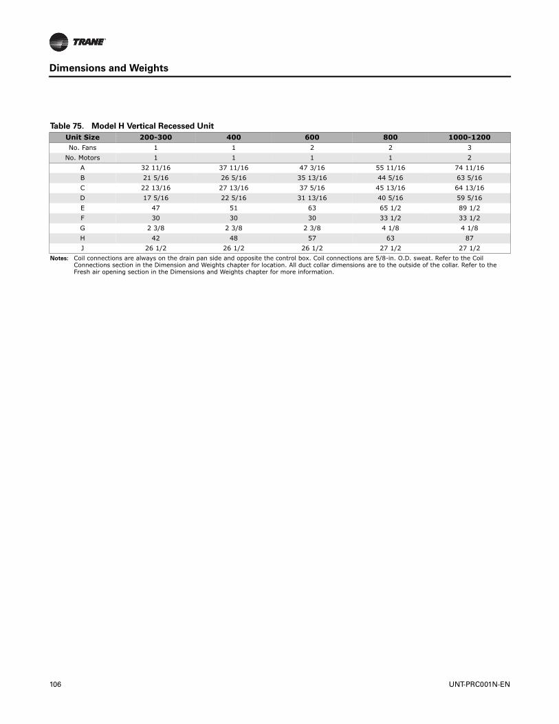
Dimensions and Weights
Table 75. Model H Vertical Recessed Unit
Unit Size 200-300 400 600 800 1000-1200No. Fans 1 1 2 2 3
No. Motors 1 1 1 1 2A 32 11/16 37 11/16 47 3/16 55 11/16 74 11/16B 21 5/16 26 5/16 35 13/16 44 5/16 63 5/16C 22 13/16 27 13/16 37 5/16 45 13/16 64 13/16D 17 5/16 22 5/16 31 13/16 40 5/16 59 5/16E 47 51 63 65 1/2 89 1/2F 30 30 30 33 1/2 33 1/2G 2 3/8 2 3/8 2 3/8 4 1/8 4 1/8H 42 48 57 63 87J 26 1/2 26 1/2 26 1/2 27 1/2 27 1/2
Notes: Coil connections are always on the drain pan side and opposite the control box. Coil connections are 5/8-in. O.D. sweat. Refer to the Coil Connections section in the Dimension and Weights chapter for location. All duct collar dimensions are to the outside of the collar. Refer to the Fresh air opening section in the Dimensions and Weights chapter for more information.
106 UNT-PRC001N-EN
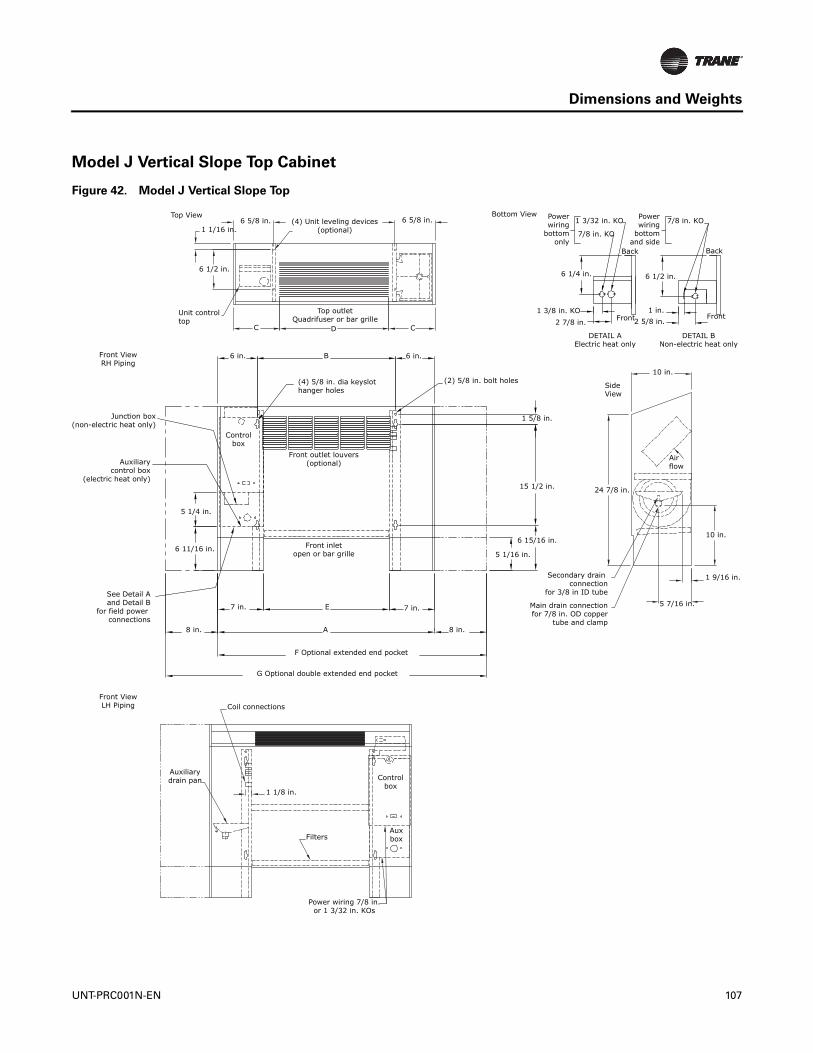
Dimensions and Weights
Model J Vertical Slope Top Cabinet
Figure 42. Model J Vertical Slope Top
Top View6 5/8 in.
1 1/16 in.
6 1/2 in.
(4) Unit leveling devices(optional)
6 5/8 in.
2 7/8 in.1 3/8 in. KO
6 1/4 in.
Powerwiring
bottomonly
7/8 in. KO
1 3/32 in. KO
Unit controltop
C D
Top outletQuadrifuser or bar grille
C
Front ViewLH Piping Coil connections
Auxiliarydrain pan
1 1/8 in.
Filters
Controlbox
Auxbox
Power wiring 7/8 in.or 1 3/32 in. KOs
10 in.
SideView
Airflow
24 7/8 in.
Secondary drain connection
for 3/8 in ID tube
Main drain connectionfor 7/8 in. OD copper
tube and clamp
5 7/16 in.
1 9/16 in.
10 in.
Bottom View
BackBack
Front Front
Powerwiring
bottomand side
7/8 in. KO
6 1/2 in.
1 in.2 5/8 in.
DETAIL AElectric heat only
DETAIL BNon-electric heat only
Front ViewRH Piping
6 in. B 6 in.
Auxiliarycontrol box
(electric heat only)
5 1/4 in.
6 11/16 in.
Controlbox
Front inletopen or bar grille
7 in. E
A
7 in.
8 in.
F Optional extended end pocket
(4) 5/8 in. dia keyslothanger holes
(2) 5/8 in. bolt holes
15 1/2 in.
6 15/16 in.
5 1/16 in.
1 5/8 in.
Front outlet louvers(optional)
8 in.
See Detail Aand Detail B
for field power connections
G Optional double extended end pocket
Junction box(non-electric heat only)
UNT-PRC001N-EN 107
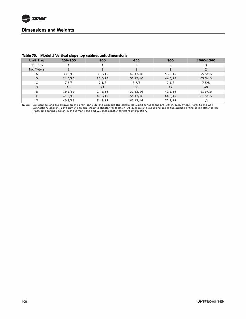
Dimensions and Weights
Table 76. Model J Vertical slope top cabinet unit dimensions
Unit Size 200-300 400 600 800 1000-1200No. Fans 1 1 2 2 3
No. Motors 1 1 1 1 2A 33 5/16 38 5/16 47 13/16 56 5/16 75 5/16B 21 5/16 26 5/16 35 13/16 44 5/16 63 5/16C 7 5/8 7 1/8 8 7/8 7 1/8 7 5/8D 18 24 30 42 60E 19 5/16 24 5/16 33 13/16 42 5/16 61 5/16F 41 5/16 46 5/16 55 13/16 64 5/16 81 5/16G 49 5/16 54 5/16 63 13/16 72 5/16 n/a
Notes: Coil connections are always on the drain pan side and opposite the control box. Coil connections are 5/8-in. O.D. sweat. Refer to the Coil Connections section in the Dimension and Weights chapter for location. All duct collar dimensions are to the outside of the collar. Refer to the Fresh air opening section in the Dimensions and Weights chapter for more information.
108 UNT-PRC001N-EN
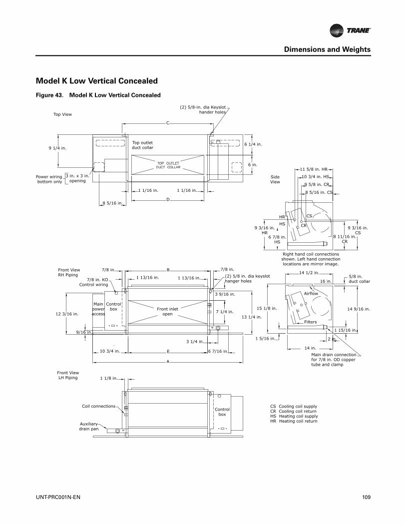
Dimensions and Weights
Model K Low Vertical Concealed
Figure 43. Model K Low Vertical Concealed
Top View
(2) 5/8-in. dia Keyslothander holes
C
9 1/4 in.
Power wiringbottom only
3 in. x 3 in.opening
8 5/16 in.
1 1/16 in.
D
1 1/16 in.
Top outletduct collar
6 1/4 in.
6 in.11 5/8 in. HR
10 3/4 in. HS
9 5/8 in. CR
8 5/16 in. CS
SideView
HR
HS9 3/16 in.
HR6 7/8 in.
HS
CS
CR 9 3/16 in.CS
8 11/16 in.CR
Right hand coil connectionsshown. Left hand connectionlocations are mirror image.
14 1/2 in.
16 in.5/8 in. duct collar
14 9/16 in.
1 15/16 in.
2 in.
Main drain connectionfor 7/8 in. OD coppertube and clamp
14 in.
1 5/16 in.
15 1/8 in.
13 1/4 in.Filters
Airflow
Front ViewRH Piping
7/8 in.
7/8 in. KOControl wiring
1 13/16 in.
B
1 13/16 in.
7/8 in.(2) 5/8 in. dia keyslothanger holes
3 9/16 in.
7 1/4 in.
3 1/4 in.
6 7/16 in.
A
E10 3/4 in.
Front inletopen
Mainpoweraccess
Controlbox
12 3/16 in.
9/16 in.
1 1/8 in.Front ViewLH Piping
Coil connections
Auxiliarydrain pan
Controlbox
CS Cooling coil supplyCR Cooling coil returnHS Heating coil supplyHR Heating coil return
UNT-PRC001N-EN 109

Dimensions and Weights
Table 77. Model K Low vertical concealed unit dimensions (in.) and weights (lb)
Unit Size 03 04 06A 41-7/16 50-15/16 59-7/16B 26-1/4 35-3/4 44-1/4C 27-15/16 36-13/16” 45-15/16D 22-5/16 31-13/16 40-5/16E 24-1/4 33-3/4 42-1/4
Operating Weight 109 139 147Shipping Weight 96 123 131
Notes: Coil connections are always on the drain pan side and opposite the control box. Coil connections are 5/8-in. O.D. sweat. Refer to the Coil Connections section in the Dimension and Weights chapter for location. All duct collar dimensions are to the outside of the collar. Refer to the Fresh air opening section in the Dimensions and Weights chapter for more information.Serviceability for some components within this unit may require panel or drain pan removal.
110 UNT-PRC001N-EN

Dimensions and Weights
Model L Low Vertical Cabinet
Figure 44. Model L Low vertical cabinet
Top View
(2) 5/8-in. dia Keyslothander holes
C
9 1/4 in.
Power wiringbottom only
3 in. x 3 in.opening
8 5/16 in.
1 1/16 in.
D
1 1/16 in.
Top outletduct collar
6 1/4 in.
6 in.11 5/8 in. HR
10 3/4 in. HS
9 5/8 in. CR
8 5/16 in. CS
SideView
HR
HS9 3/16 in.
HR6 7/8 in.
HS
CS
CR 9 3/16 in.CS
8 11/16 in.CR
Right hand coil connectionsshown. Left hand connectionlocations are mirror image.
14 1/2 in.
16 in.5/8 in. duct collar
14 9/16 in.
1 15/16 in.
2 in.
Main drain connectionfor 7/8 in. OD coppertube and clamp
14 in.
1 5/16 in.
15 1/8 in.
13 1/4 in.Filters
Airflow
Front ViewRH Piping
7/8 in.
7/8 in. KOControl wiring
1 13/16 in.
B
1 13/16 in.
7/8 in.(2) 5/8 in. dia keyslothanger holes
3 9/16 in.
7 1/4 in.
3 1/4 in.
6 7/16 in.
A
E10 3/4 in.
Front inletopen
Mainpoweraccess
Controlbox
12 3/16 in.
9/16 in.
1 1/8 in.Front ViewLH Piping
Coil connections
Auxiliarydrain pan
Controlbox
CS Cooling coil supplyCR Cooling coil returnHS Heating coil supplyHR Heating coil return
UNT-PRC001N-EN 111
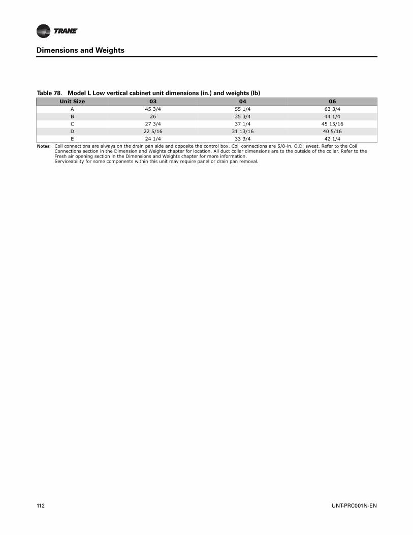
Dimensions and Weights
Table 78. Model L Low vertical cabinet unit dimensions (in.) and weights (lb)
Unit Size 03 04 06A 45 3/4 55 1/4 63 3/4B 26 35 3/4 44 1/4C 27 3/4 37 1/4 45 15/16D 22 5/16 31 13/16 40 5/16E 24 1/4 33 3/4 42 1/4
Notes: Coil connections are always on the drain pan side and opposite the control box. Coil connections are 5/8-in. O.D. sweat. Refer to the Coil Connections section in the Dimension and Weights chapter for location. All duct collar dimensions are to the outside of the collar. Refer to the Fresh air opening section in the Dimensions and Weights chapter for more information.Serviceability for some components within this unit may require panel or drain pan removal.
112 UNT-PRC001N-EN
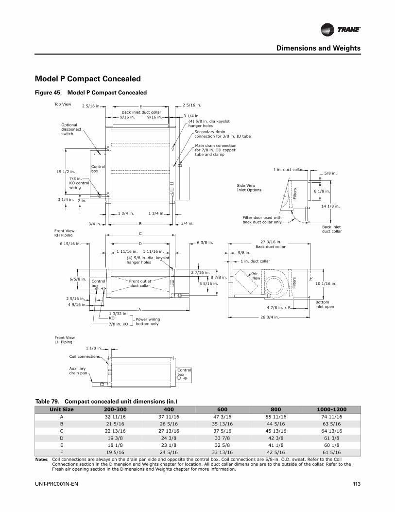
Dimensions and Weights
Model P Compact Concealed
Figure 45. Model P Compact Concealed
Top View
Front ViewRH Piping
Front ViewLH Piping
Side ViewInlet Options
2 5/16 in. EBack inlet duct collar
9/16 in. 9/16 in.
Optionaldiscoonectswitch
15 1/2 in.
7/8 in. KO control wiring
3 1/4 in. 2 in.
3/4 in.
1 3/4 in. 1 3/4 in.
B
C
D6 15/16 in.
Control box
2 5/16 in.
3 1/4 in.(4) 5/8 in. dia keyslothanger holes
Secondary drainconnection for 3/8 in. ID tube
Main drain connectionfor 7/8 in. OD copper tube and clamp
1 in. duct collar5/8 in.
6 1/8 in.
14 1/8 in.
Back inlet duct collar
Filter door used with back duct collar only
Filte
rs
3/4 in.
1 11/16 in. 1 11/16 in.
6 3/8 in.
2 7/16 in.8 7/8 in.
5 5/16 in.6/5/8 in. Control
box
2 5/16 in.4 9/16 in.
1 3/32 in.KO7/8 in. KO
A
Power wiringbottom only
1 1/8 in.
Coil connections
Auxiliarydrain pan
Controlbox
27 3/16 in.Back duct collar
5/8 in.
1 in. duct collar
Airflow
10 1/16 in.
4 7/8 in. x F
26 3/4 in.
Bottom inlet open
Filte
rs
(4) 5/8 in. dia keyslot hanger holes
Front outletduct collar
Table 79. Compact concealed unit dimensions (in.)
Unit Size 200-300 400 600 800 1000-1200A 32 11/16 37 11/16 47 3/16 55 11/16 74 11/16B 21 5/16 26 5/16 35 13/16 44 5/16 63 5/16C 22 13/16 27 13/16 37 5/16 45 13/16 64 13/16D 19 3/8 24 3/8 33 7/8 42 3/8 61 3/8E 18 1/8 23 1/8 32 5/8 41 1/8 60 1/8F 19 5/16 24 5/16 33 13/16 42 5/16 61 5/16
Notes: Coil connections are always on the drain pan side and opposite the control box. Coil connections are 5/8-in. O.D. sweat. Refer to the Coil Connections section in the Dimension and Weights chapter for location. All duct collar dimensions are to the outside of the collar. Refer to the Fresh air opening section in the Dimensions and Weights chapter for more information.
UNT-PRC001N-EN 113

Dimensions and Weights
Unit Weights
Table 80. Operating weights (pounds)
Unit size Cabinet models Concealed models Recessed modelsLow vertical cabinet
modelsLow vertical
concealed models02 97 81 78 n/a n/a03 97 81 78 125 10904 125 109 88 155 13906 155 139 128 164 14708 164 147 139 n/a n/a10 218 200 253 n/a n/a12 218 200 253 n/a n/a
Table 81. Shipping weights (pounds)
Unit size Cabinet models Concealed models Recessed modelsLow vertical cabinet
modelsLow vertical
concealed models02 84 68 68 n/a n/a03 84 68 68 112 9604 112 96 78 139 12306 139 123 118 148 13108 148 131 129 n/a n/a10 200 182 243 n/a n/a12 200 182 243 n/a n/a
114 UNT-PRC001N-EN

Dimensions and Weights
Coil Connections
Fan Coil Vertical Units
Figure 46. Coil connections for fan coil vertical units
8 3/16 in. RHS
5 5/16 in. CS
4 7/8 in. RHR
4 3/8 in. CR
4 in. HS
2 5/16 in. HR
Dimensions are typicalto vertical unit styles.
Vertical Concealed
Vertical Recessed (recess panel not shown)
Vertical Cabinet
Vertical SlopeTop
RHSCS
RHSCR HR
HS
CSRHR
CR HR
HS
RHRRHR
RHS
23 1/4 in.RHR
19 15/16 in.RHS
18 11/16 in.HS
20 1/2 in.HR
20 13/16 in.CR
21 13/16 in.CS
Bottom of Vertical Units
CSCR
HRHS
UNT-PRC001N-EN 115

Dimensions and Weights
Fan Coil Horizontal Units
Figure 47. Coil connections for fan coil horizontal units
Horizontal Concealed
Horizontal Recessed(Recess panel not shown)
HR
HSCR
RHS
CSRHR
1 in.
7/16 in.
22 3/8 in. CS
21 3/8 in. CR
21 1/16 in. HR
19 5/16 in. HSDimensions are typical to horizontal unit styles.
5 5/16 in.CS
4 7/8 in.RHS
4 3/8 in.CR
8 3/16 in.RHS
Horizontal Cabinet
HR
HSCR
RHR
CSRHS
20 9/16 in. RHS
23 7/8 in. RHR
2 5/16 in. HR4 in. HS
116 UNT-PRC001N-EN

Dimensions and Weights
Figure 48. Coil connections for DX coil and heat pump
Front view
Top view
Back of unit
4.25
1.50
Suction0.50 ODSize 06
0.625 ODSize 08
0.750 ODSize 10, 12
14
42
Liquid0.38 OD
UNT-PRC001N-EN 117

Dimensions and Weights
Refrigerant Connection Detail
Figure 49. DX and heat pump connections
Front view
Top view
4.25
1.50
Suction0.50 ODSize 600
0.625 ODSize 800
0.75 ODSize 100, 120
Liquid0.38 OD
14
Back of unit
42
118 UNT-PRC001N-EN
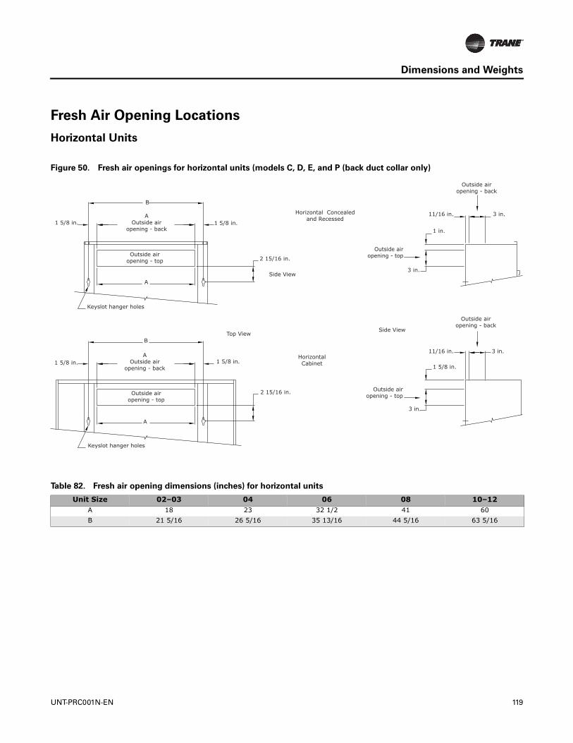
Dimensions and Weights
Fresh Air Opening Locations
Horizontal Units
Figure 50. Fresh air openings for horizontal units (models C, D, E, and P (back duct collar only)
1 5/8 in.
B
AOutside air
opening - back
Outside airopening - top
A
Keyslot hanger holes
B
AOutside air
opening - back1 5/8 in.
Outside airopening - top
Keyslot hanger holes
1 5/8 in.
2 15/16 in.
Top View
HorizontalCabinet
Horizontal Concealedand Recessed
Outside airopening - top
3 in.
1 in.
11/16 in. 3 in.
Side View
Outside airopening - top
3 in.
1 5/8 in.
11/16 in.
A
1 5/8 in.
2 15/16 in.
Side View
Outside airopening - back
3 in.
Outside airopening - back
Table 82. Fresh air opening dimensions (inches) for horizontal units
Unit Size 02–03 04 06 08 10–12A 18 23 32 1/2 41 60B 21 5/16 26 5/16 35 13/16 44 5/16 63 5/16
UNT-PRC001N-EN 119
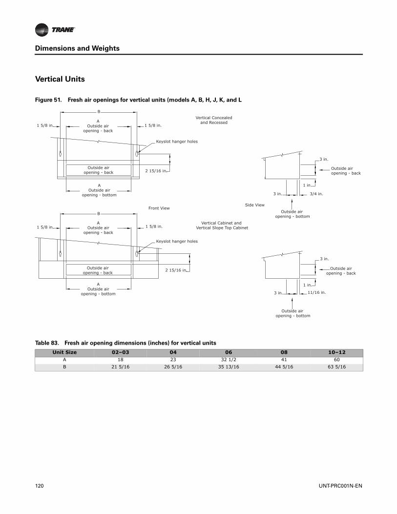
Dimensions and Weights
Vertical Units
Figure 51. Fresh air openings for vertical units (models A, B, H, J, K, and L
1 5/8 in.
B
AOutside air
opening - back
Outside airopening - back
AOutside air
opening - bottom
B
1 5/8 in.A
Outside airopening - back
Outside airopening - back
AOutside air
opening - bottom
2 15/16 in.
Keyslot hanger holes
1 5/8 in.Vertical Cabinet and
Vertical Slope Top Cabinet
Front ViewSide View
Vertical Concealedand Recessed
Keyslot hanger holes
2 15/16 in.
1 5/8 in.
3 in. 3/4 in.
1 in.
3 in.
Outside airopening - back
Outside air opening - bottom
Outside air opening - bottom
3 in. 11/16 in.
1 in.
Outside airopening - back
3 in.
Table 83. Fresh air opening dimensions (inches) for vertical units
Unit Size 02–03 04 06 08 10–12A 18 23 32 1/2 41 60B 21 5/16 26 5/16 35 13/16 44 5/16 63 5/16
120 UNT-PRC001N-EN
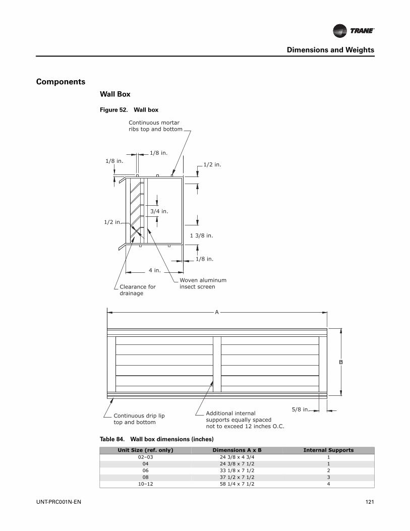
Dimensions and Weights
Components
Wall Box
Figure 52. Wall box
Table 84. Wall box dimensions (inches)
Unit Size (ref. only) Dimensions A x B Internal Supports02–03 24 3/8 x 4 3/4 1
04 24 3/8 x 7 1/2 106 33 1/8 x 7 1/2 208 37 1/2 x 7 1/2 3
10–12 58 1/4 x 7 1/2 4
Additional internalsupports equally spacednot to exceed 12 inches O.C.
Continuous drip liptop and bottom
B
A
5/8 in.
1/2 in.
1 3/8 in.
1/8 in.
Woven aluminuminsect screenClearance for
drainage
4 in.
1/2 in.
3/4 in.
1/8 in.1/8 in.
Continuous mortarribs top and bottom
UNT-PRC001N-EN 121
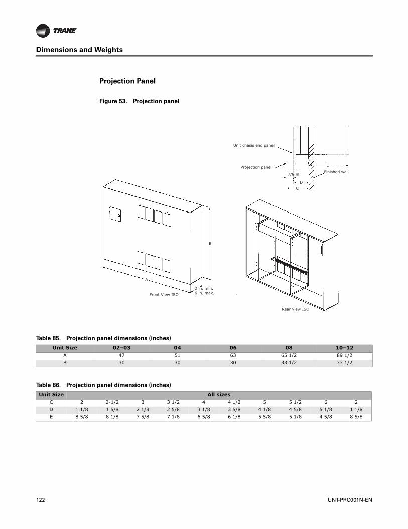
Dimensions and Weights
Projection Panel
Figure 53. Projection panel
Finished wall
E
Unit chasis end panel
Projection panel
7/8 in.
DC
A
2 in. min.6 in. max.
B
Front View ISO
Rear view ISO
Table 85. Projection panel dimensions (inches)
Unit Size 02–03 04 06 08 10–12A 47 51 63 65 1/2 89 1/2B 30 30 30 33 1/2 33 1/2
Table 86. Projection panel dimensions (inches)
Unit Size All sizesC 2 2-1/2 3 3 1/2 4 4 1/2 5 5 1/2 6 2D 1 1/8 1 5/8 2 1/8 2 5/8 3 1/8 3 5/8 4 1/8 4 5/8 5 1/8 1 1/8E 8 5/8 8 1/8 7 5/8 7 1/8 6 5/8 6 1/8 5 5/8 5 1/8 4 5/8 8 5/8
122 UNT-PRC001N-EN
Mechanical Specifications
Performance Data
Capacity: Unit capacities are certified under Industry Room Fan Coil Air Conditioner Certification Program in accordance with AHRI Standard 440-2008.
Safety: All standard units are UL listed in the United States and Canada and comply with NFPA 90A requirements.
Construction
All Units
The unit includes a chassis, coil(s), fan wheel(s), fan casing(s), fan board and motor(s). Units also include a noncorrosive, ABS main drain pan, positively sloped in every plane and insulated with closed-cell insulation. Horizontal units and all units with standard piping packages also include a thermoplastic auxiliary drain pan. Steel parts exposed to moisture are galvanized. The fan board assembly and both drain pans are easily removable. The fan board assembly includes a quick-disconnect motor plug. The chassis construction is 18-gauge galvanized steel, and continuous throughout the unit. The unit is acoustically and thermally insulated with closed-cell insulation. All panels are made rigid by channel forming.
Vertical Cabinet and Slope Top Units
Front panel fabrication is 16-gauge galvanized steel. All other panels are 18-gauge galvanized steel. The discharge grille is recessed to resist condensate formation. Hinged access door construction is 20-gauge steel and is flush with top panel.
Horizontal Cabinet Units
All panels are 18-gauge galvanized steel, including the bottom panel. Discharge grille is recessed to resist condensate formation. The hinged access door is flush with front panel. Bottom panels ship with tamperproof screw fasteners and a safety chain.
Concealed/Recessed Units
Exposed panels on recessed units are 18-gauge steel construction and ship separate from the unit. Bottom panels on horizontal recessed models ship standard with tamperproof screw fasteners and a safety chain. Horizontal recessed units feature a telescoping panel to allow the panel to be adjusted to line up flush with the ceiling. The telescoping panel extends 1.25 inches to 2 inches depending on the configuration of airflow.
Low Vertical Unit
Front panels are of 16-gauge galvanized steel. All cabinet parts are made rigid by channel forming. End panel is removable for piping access. Hinged access door construction is 20-gauge steel and flush with top panel.
Unit Finish
All cabinet parts and exposed recessed panels are cleaned, bonderized, phosphatized, and painted with a baked powder finish available in six decorator colors. Standard finish meets ASTM B117 specifications (salt spray test).
Fans
The galvanized metal fan wheels are centrifugal forward-curved and double-width. Fan wheels and housings are corrosion resistant. Fan housing construction is formed sheet metal. Low vertical units utilize an aluminum tangential wheel design.
Motors
All motors are brushless DC (BLDC)/electronically commutated motors (ECM) factory-programmed and run-tested in assembled units. The motor controller is mounted in a touch-safe
UNT-PRC001N-EN 123

Mechanical Specifications
control box with a built-in integrated user interface and LED tachometer. If adjustments are needed, motor parameters can be adjusted through momentary contact switches accessible without factory service personnel on the motor control board.
Motors will soft-ramp between speeds to lessen the acoustics due to sudden speed changes. Motors can be operated at three speeds or with a field-supplied variable speed controller. The motor will choose the highest speed if there are simultaneous/conflicting speed requests.
All motors have integral thermal overload protection with a maximum ambient operating temperature of 104°F and are permanently lubricated. Motors are capable of starting at 50 percent of rated voltage and operating at 90 percent of rated voltage on all speed settings. Motors can operate up to 10 percent over voltage.
Extended End Pockets
On vertical or horizontal cabinet units, an 8-inch extended end pocket is available on the piping end. On vertical cabinet and vertical slope top units, an 8-inch extended end pocket is available on both the piping and control side.
Tamperproof Locks
Key-operated locking access doors and/or panels will help prevent nuisance tampering with unit and/or controls. Tamper proof locks are available on vertical cabinet, horizontal cabinet, vertical recessed, vertical slope top, and low vertical units.
Leveling Feet
Refrigerator type screw-in bolts to level the unit are available on vertical and low vertical cabinet units.
Controls
Controls options are: fan speed control, customer supplied terminal interface, and Tracer® ZN010, ZN510, ZN520, and UC400-B. A variety of inputs and outputs are available for the control interface and Tracer® controller options. A disconnect switch (for non-electric heat units), fused transformer, contactor(s), and terminal strip are provided with the control interface and Tracer® controller options.
Customer Supplied Terminal Interface
The control interface is intended to be used with a field-supplied, low-voltage thermostat or controller. The control box contains a relay board which includes a line voltage to 24-volt transformer, quiet contactors (for electric heat units), and an optional disconnect switch. All end devices are wired to a low-voltage terminal block and are run-tested, so the only a power connection and thermostat connection is needed to commission the unit. Changeover sensors and controls are provided whenever a change-over coil is selected. When N.O. valves are selected, inverting relays are provided for use with standard thermostats.
Fan Speed Control
The fan speed control is available with or without the control interface option and is available as wall-mount or unit-mount. The speed control incorporates a 0-10 VDC signal providing limitless control of the motor RPM between the factory set low and high speeds. The control box contains a line voltage to 24-volt transformer, ECM motor controller, and an optional disconnect switch.
Disconnect Switch
A unit mounted disconnect switch is available as a standard option on all units.
124 UNT-PRC001N-EN

Mechanical Specifications
Coils
All water coils are proof-tested at 300 psig (air) and leak-tested at 100 psig (air under water). Maximum main coil working pressure is 300 psig. Maximum entering water temperature is 200°F. Tubes and u-bends are 3/8-inch OD copper. Fins are aluminum and are mechanically bonded to the copper tubes. Coil stub-outs are 5/8-inch OD copper tubing.
Reheat Coils
Reheat coils are available for use with both hot water and steam. Hot water maximum working pressure is 300 psig, and the maximum entering water temperature is 200°F. The steam coil maximum working pressure is 15 psig. The reheat coils are constructed of single circuit 5/8-inch copper tubes with aluminum fins. Piping connections are expanded to accept standard copper tubing 5/8-inch OD.
Electric Heat Coil
The auxiliary electric heating coil is provided as either the total source of heat or auxiliary intermediate season heating. The electric heat coils are located in the preheat position, and are the open-wire type. The coils are a nickel chromium element design. The electric heat operates at the same voltage as the unit, and only a single power connection is necessary.
All units with factory-mounted electric heat are UL-listed and interlocked with the fan motor switch. A call for electric heat operation will turn the fan on. Motors controls are synchronized with fan/valve operation to ensure safe operation and to ensure that two modes of heat are not operating simultaneously. A transformer is supplied on any voltage unit, eliminating the need for field installation of a step-down transformer. Unit-mounted quiet magnetic relays are supplied on all voltages. A high temperature cutout with automatic reset is provided as an integral part of the elements to de-energize the electric heat in the event of a malfunction.
Refrigerant Coil
Direct expansion coils contain copper tubes mechanically expanded into evenly spaced aluminum fins. All coils are leak tested at 650 psig. Maximum standard operating conditions are 650 psig at 127°F with R410A. Distributors are sized consistently with capacity of coil. A thermostatic expansion valve (TXV) is factory selected and installed for a wide-range of control to maintain optimum control of superheat. Coils are shipped with a dry nitrogen holding charge.
DX and Heat Pump Coils
Direct expansion coils contain copper tubes mechanically expanded into evenly spaced aluminum fins. All coils are leak tested at 650 psig. Maximum standard operating conditions are 650 psig at 127°F with R410A. Distributors are sized consistently with capacity of coil. A thermostatic expansion valve (TXV) is factory-selected and installed for a wide-range of control to maintain optimum control of superheat. Coils are shipped with a dry nitrogen holding charge.
Filters
Filters are concealed from sight and easily removable. Filters are located behind an integral access door on horizontal type units. Filters are either 1-inch throwaway or 1-inch MERV 8.
Units equipped with 1-inch MERV 8 filters have a rating based on ASHRAE Standard 52.2. The average dust spot efficiency is no less than 35 to 40 percent when tested in accordance with ASHRAE 52.1 atmospheric dust spot method.
Units equipped with 1-inch MERV 13 filters have a rating based on ASHRAE Standard 52.2. The average dust spot efficiency is no less than 90 percent efficiency on 1-3 micron particles and greater than 90 percent efficiency on 3-10 micron particles when tested in accordance with ASHRAE Test Standard 52.2.
UNT-PRC001N-EN 125
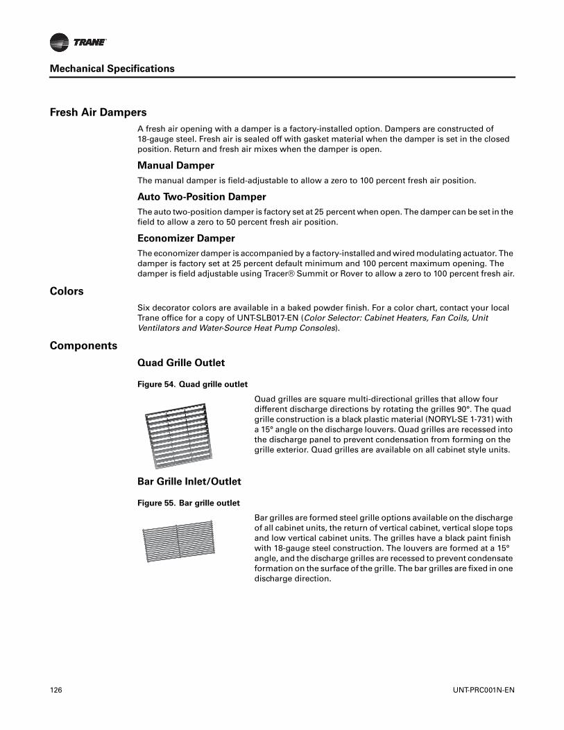
Mechanical Specifications
Fresh Air Dampers
A fresh air opening with a damper is a factory-installed option. Dampers are constructed of 18-gauge steel. Fresh air is sealed off with gasket material when the damper is set in the closed position. Return and fresh air mixes when the damper is open.
Manual Damper
The manual damper is field-adjustable to allow a zero to 100 percent fresh air position.
Auto Two-Position Damper
The auto two-position damper is factory set at 25 percent when open. The damper can be set in the field to allow a zero to 50 percent fresh air position.
Economizer Damper
The economizer damper is accompanied by a factory-installed and wired modulating actuator. The damper is factory set at 25 percent default minimum and 100 percent maximum opening. The damper is field adjustable using Tracer® Summit or Rover to allow a zero to 100 percent fresh air.
Colors
Six decorator colors are available in a baked powder finish. For a color chart, contact your local Trane office for a copy of UNT-SLB017-EN (Color Selector: Cabinet Heaters, Fan Coils, Unit Ventilators and Water-Source Heat Pump Consoles).
Components
Quad Grille Outlet
Bar Grille Inlet/Outlet
Figure 54. Quad grille outlet
Quad grilles are square multi-directional grilles that allow four different discharge directions by rotating the grilles 90°. The quad grille construction is a black plastic material (NORYL-SE 1-731) with a 15° angle on the discharge louvers. Quad grilles are recessed into the discharge panel to prevent condensation from forming on the grille exterior. Quad grilles are available on all cabinet style units.
Figure 55. Bar grille outlet
Bar grilles are formed steel grille options available on the discharge of all cabinet units, the return of vertical cabinet, vertical slope tops and low vertical cabinet units. The grilles have a black paint finish with 18-gauge steel construction. The louvers are formed at a 15° angle, and the discharge grilles are recessed to prevent condensate formation on the surface of the grille. The bar grilles are fixed in one discharge direction.
126 UNT-PRC001N-EN
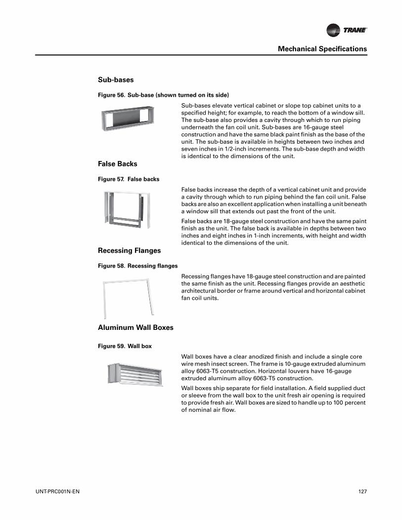
Mechanical Specifications
Sub-bases
False Backs
Recessing Flanges
Aluminum Wall Boxes
Figure 56. Sub-base (shown turned on its side)
Sub-bases elevate vertical cabinet or slope top cabinet units to a specified height; for example, to reach the bottom of a window sill. The sub-base also provides a cavity through which to run piping underneath the fan coil unit. Sub-bases are 16-gauge steel construction and have the same black paint finish as the base of the unit. The sub-base is available in heights between two inches and seven inches in 1/2-inch increments. The sub-base depth and width is identical to the dimensions of the unit.
Figure 57. False backs
False backs increase the depth of a vertical cabinet unit and provide a cavity through which to run piping behind the fan coil unit. False backs are also an excellent application when installing a unit beneath a window sill that extends out past the front of the unit.
False backs are 18-gauge steel construction and have the same paint finish as the unit. The false back is available in depths between two inches and eight inches in 1-inch increments, with height and width identical to the dimensions of the unit.
Figure 58. Recessing flanges
Recessing flanges have 18-gauge steel construction and are painted the same finish as the unit. Recessing flanges provide an aesthetic architectural border or frame around vertical and horizontal cabinet fan coil units.
Figure 59. Wall box
Wall boxes have a clear anodized finish and include a single core wire mesh insect screen. The frame is 10-gauge extruded aluminum alloy 6063-T5 construction. Horizontal louvers have 16-gauge extruded aluminum alloy 6063-T5 construction.
Wall boxes ship separate for field installation. A field supplied duct or sleeve from the wall box to the unit fresh air opening is required to provide fresh air. Wall boxes are sized to handle up to 100 percent of nominal air flow.
UNT-PRC001N-EN 127

Mechanical Specifications
Projection Panels
Piping Package
All piping packages are proof-tested at 300 psig (air) and leak tested at 100 (air under water.) The maximum working pressure of the interconnecting piping is 300 psig.
The piping package is designed so that any condensation is directed into the UniTrane auxiliary drain pan. Insulation of piping package is not required.
Control valves are mounted in all factory piping packages. All piping packages are factory-installed and come in a variety of options:
• Basic: Shut-off ball valve on the supply line. Control valve and shut-off ball valve on the return line.
• Basic with manual circuit setter: Shut-off ball valve on the supply line. Control valve and manual circuit setter on the return line.
• Deluxe with manual circuit setter: Union, strainer, P/T port, and shut-off ball valve on the supply line. Union, control valve and manual circuit setter on the return line.
• Deluxe with auto flow: Union, strainer, P/T port, and shut-off ball valve on the supply line. Union, control valve, auto flow valve, P/T port and shut-off ball valve on the return line.
Two Position Control Valves
Two position control valves are ball valve designed with zero leakage. The ball valve incorporates self-cleaning technology to provide superior clog resistance. The actuator is easily removable for service without removing the valve body. Actuators are capacitor discharge return.
Modulating and Analog (2-10 VDC) Control Valves
Modulating and analog control valves are ball valve designed with zero leakage. The ball valve incorporates self-cleaning technology to provide superior clog resistance. If the actuators fail, they can be easily removed for servicing without removing the valve body.
Figure 60. Projection panel
Projection panels allow semi-recessing of vertical recessed units.
Panels are 16-gauge steel construction, painted with a baked powder finish. They are available in projection depths ranging from two inches to six inches in 1/2-inch increments. There is a distance of 7/8 inch between the projection panel and the front of the unit.
Figure 61. Control valve MaterialMedia
TemperatureWorking Pressure
Differential Pressure
Close off Pressure
Body - Forged Brass 36°F min 360 psig 40 psig 75 psigBall - Chrome Plated
Brass 200°F max
Stem - BrassSeats - PTFE
O-Rings - EPDM (lubricated)
128 UNT-PRC001N-EN

Mechanical Specifications
End Valves
Each piping package includes a ball valve on the entering water pipe and one of the following end valve on the leaving water pipe:
• Ball valve
• Manual circuit setter
• Auto circuit setter
End valve serves as the field connection points on all the Fan Coil piping packages.
Ball Valve
Ball valves, also known as stop valves, allow the unit to be cut off for service purposes. These valves have a two inch handle that rotates 90 degree to a fully open position.
Manual Circuit Setter
A manual circuit setter acts as both a flow setting device and a stop valve. This valve allows water flow through the unit to be set quickly and accurately. The manual circuit setter includes ¼ in. Schrader ports in the valve body. These ports are used to measure the pressure drop across the valve. This pressure drop can be compared to factory supplied curves that relate the pressure drop to a specific flow rate. This valve also has a memory stop that helps find the correct setting quickly.
Figure 62. Ball valve MaterialMedia
Temperature Working PressureBody - Brass 0°F min 600 psig maxSeat - RPTFE 400°F maxBall - Brass
Stem - BrassStem Packing - RPTFE
Nut - Corrosion Resistant Plated Steel
Retainer - BrassHandle - Plated Steel / Insulated
Polyvinyl
Gland - Brass
Figure 63. Manual circuit
setter Material Temperature Working PressureBody - Bronze 250°F max 300 psig maxSeats - Teflon®
Internal Components - Brass, Teflon®, EPDM
Schrader Valve Connections - Brass 1/4 in.
Indicator Plate - Stainless Steel
Pointer - Die Cast Zinc
UNT-PRC001N-EN 129
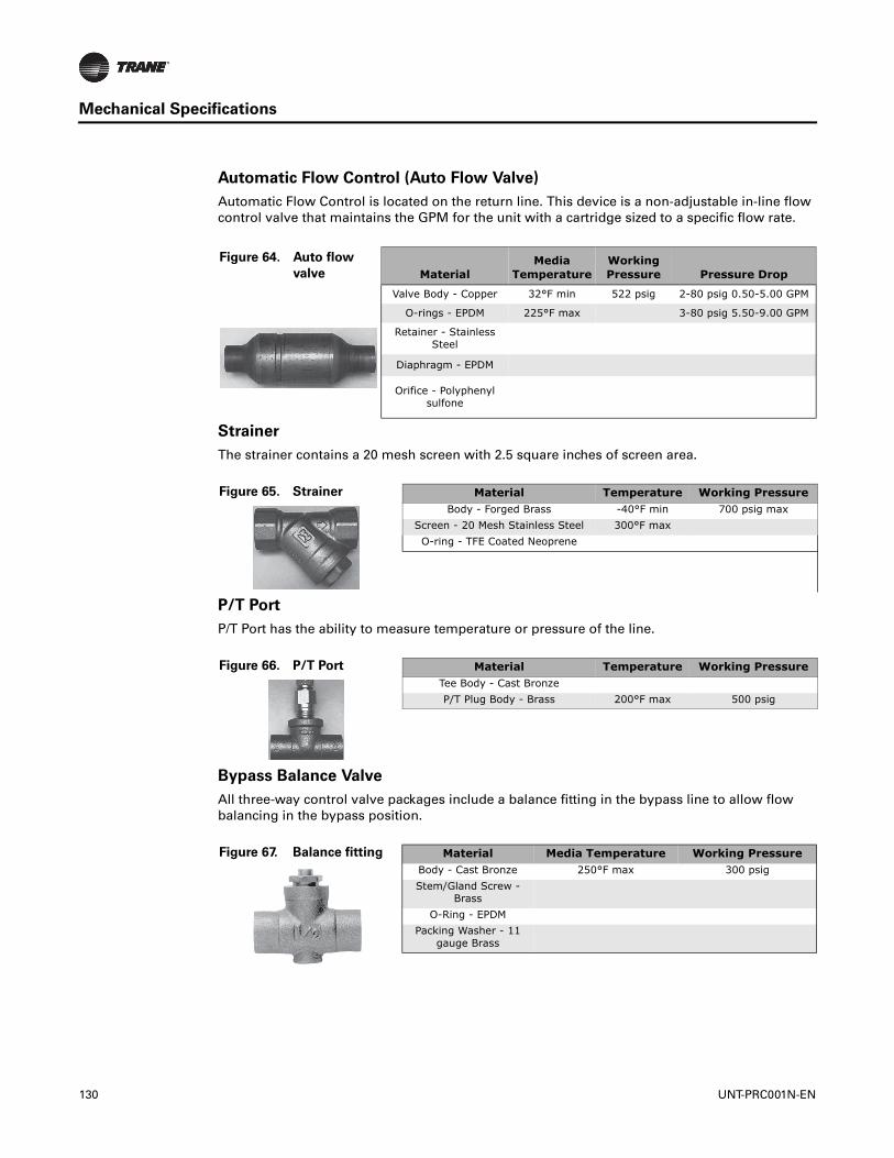
Mechanical Specifications
Automatic Flow Control (Auto Flow Valve)
Automatic Flow Control is located on the return line. This device is a non-adjustable in-line flow control valve that maintains the GPM for the unit with a cartridge sized to a specific flow rate.
Strainer
The strainer contains a 20 mesh screen with 2.5 square inches of screen area.
P/T Port
P/T Port has the ability to measure temperature or pressure of the line.
Bypass Balance Valve
All three-way control valve packages include a balance fitting in the bypass line to allow flow balancing in the bypass position.
Figure 64. Auto flow
valve MaterialMedia
TemperatureWorking Pressure Pressure Drop
Valve Body - Copper 32°F min 522 psig 2-80 psig 0.50-5.00 GPM
O-rings - EPDM 225°F max 3-80 psig 5.50-9.00 GPM
Retainer - Stainless Steel
Diaphragm - EPDM
Orifice - Polyphenyl sulfone
Figure 65. Strainer Material Temperature Working PressureBody - Forged Brass -40°F min 700 psig max
Screen - 20 Mesh Stainless Steel 300°F maxO-ring - TFE Coated Neoprene
Figure 66. P/T Port Material Temperature Working PressureTee Body - Cast BronzeP/T Plug Body - Brass 200°F max 500 psig
Figure 67. Balance fitting Material Media Temperature Working PressureBody - Cast Bronze 250°F max 300 psigStem/Gland Screw -
BrassO-Ring - EPDM
Packing Washer - 11 gauge Brass
130 UNT-PRC001N-EN

Mechanical Specifications
Union
Figure 68. Union Material
Nut—Forged Brass
Body—Copper
Tail—Copper
UNT-PRC001N-EN 131
Ingersoll Rand has a policy of continuous product and product data improvement and reserves the right to change design and specifications without notice.We are committed to using environmentally conscious print practices.
Ingersoll Rand (NYSE:IR) advances the quality of life by creating comfortable, sustainable and efficientenvironments. Our people and our family of brands—including Club Car®, Ingersoll Rand®, Thermo King® andTrane®—work together to enhance the quality and comfort of air in homes and buildings; transport and protectfood and perishables; and increase industrial productivity and efficiency. We are a global business committed to aworld of sustainable progress and enduring results.
The AHRI Certified mark indicates Ingersoll Rand’s participation in the AHRI Certification program. For verification of individual certified products, go to www.ahridirectory.org.
ingersollrand.com
©2018 Ingersoll RandUNT-PRC001N-EN 06 Jun 2018Supersedes UNT-PRC001M-EN (Apr 2017)
Related Documents