Unified analysis of kinematic and inertial earthquake pile responses via the single-input response spectrum method K. Kojima, K. Fujita, I. Takewaki n Department of Architecture & Architectural Engineering, Graduate School of Engineering, Kyoto University, Kyotodaigaku-Katsura, Nishikyo, Kyoto 615-8540, Japan article info Article history: Received 23 August 2013 Received in revised form 13 March 2014 Accepted 18 March 2014 Available online 12 April 2014 Keywords: Response spectrum method Structure–pile–soil system Complex modal combination Kinematic effect Inertial effect Superposition rule Bedrock input abstract In the seismic response of a structure–pile–soil system, a kinematic response due to the forced displacement of the surface ground is important, especially in a soft ground, together with the inertial response due to the inertial forces from superstructures. In this paper it is shown that a response spectrum method in terms of complex modal quantities can be used in the evaluation of the maximum kinematic and inertial seismic responses of the structure–pile–soil system to the ground motion defined at the engineering bedrock surface as an acceleration response spectrum. The notable point is that the kinematic response, the inertial response and the total response can be evaluated by the same analysis model and method by changing the model parameters. Then it is discussed which of the simple sum or the SRSS of the kinematic and inertial responses is appropriate even in resonant cases for the evaluation of the maximum pile-head bending moment. It is concluded through many examples that the validity of the simple sum or the SRSS depends on the relation between the fundamental natural period of the surface ground and that of the superstructure while an averaged evaluation is valid in resonant cases. & 2014 Elsevier Ltd. All rights reserved. 1. Introduction 1.1. Conventional method for estimating seismic pile response For the pile design under earthquake loading, the method for predicting the pile response is important. In the evaluation of the bending moment in a pile, both the effect of the forced displace- ment of a free-field ground (action 1) and the effect of the inertial force from a superstructure (action 2) as shown in Fig. 1 have to be taken into account in an appropriate manner (for example [1–11]). However these two effects have different characteristics and it seems difficult to include these in a simple way keeping a reasonable accuracy. Conventionally the following two methods have been used in practice. 1.1.1. Direct method The most well-known method is the direct method. This method uses a complete structure–pile–soil system in which the soil resistance around a pile is modeled by a spring or a finite element system. The spring model is known to be practical once its accuracy is confirmed by the comparison with other methods (a finite element system, a continuum model or physical experi- ment). The earthquake ground motion is input into the engineer- ing bedrock. Although the finite element method has much flexibility, it has the following issues to be resolved when used in the practical design. (1) Three-dimensional analysis of soil and pile elements requires huge computational load and resources. (2) Deformation compatibility between soil and pile elements is difficult to satisfy and requires a constraint on the selection of finite elements [12]. For example the program ‘FLUSH’ [13] uses a linear displacement in soil elements and a cubic displacement in pile elements which result in the deformation incompatibility. 1.1.2. Substructure method Another well-known and practical method is the substructure method (see Fig. 2). The free-field ground motion is computed first to the engineering bedrock input and that is re-input to the structure–pile system. This method is aimed at superposing simply the response (kinematic response) due to the forced displacement of the free-field ground and the response (inertial response) due to the inertial force from a superstructure. There are two methods in the substructure method, i.e. the static method Contents lists available at ScienceDirect journal homepage: www.elsevier.com/locate/soildyn Soil Dynamics and Earthquake Engineering http://dx.doi.org/10.1016/j.soildyn.2014.03.014 0267-7261/& 2014 Elsevier Ltd. All rights reserved. n Corresponding author. Tel.: þ81 75 383 3294; fax: þ81 75 383 3297. E-mail address: [email protected] (I. Takewaki). Soil Dynamics and Earthquake Engineering 63 (2014) 36–55

Unified Analysis of Kinematic and Inertial Earthquake Pile Responses
Dec 21, 2015
soil pile interation
Welcome message from author
This document is posted to help you gain knowledge. Please leave a comment to let me know what you think about it! Share it to your friends and learn new things together.
Transcript
Unified analysis of kinematic and inertial earthquake pile responsesvia the single-input response spectrum method
K. Kojima, K. Fujita, I. Takewaki n
Department of Architecture & Architectural Engineering, Graduate School of Engineering, Kyoto University, Kyotodaigaku-Katsura, Nishikyo,Kyoto 615-8540, Japan
a r t i c l e i n f o
Article history:Received 23 August 2013Received in revised form13 March 2014Accepted 18 March 2014Available online 12 April 2014
Keywords:Response spectrum methodStructure–pile–soil systemComplex modal combinationKinematic effectInertial effectSuperposition ruleBedrock input
a b s t r a c t
In the seismic response of a structure–pile–soil system, a kinematic response due to the forceddisplacement of the surface ground is important, especially in a soft ground, together with the inertialresponse due to the inertial forces from superstructures. In this paper it is shown that a responsespectrum method in terms of complex modal quantities can be used in the evaluation of the maximumkinematic and inertial seismic responses of the structure–pile–soil system to the ground motion definedat the engineering bedrock surface as an acceleration response spectrum. The notable point is that thekinematic response, the inertial response and the total response can be evaluated by the same analysismodel and method by changing the model parameters. Then it is discussed which of the simple sum orthe SRSS of the kinematic and inertial responses is appropriate even in resonant cases for the evaluationof the maximum pile-head bending moment. It is concluded through many examples that the validity ofthe simple sum or the SRSS depends on the relation between the fundamental natural period of thesurface ground and that of the superstructure while an averaged evaluation is valid in resonant cases.
& 2014 Elsevier Ltd. All rights reserved.
1. Introduction
1.1. Conventional method for estimating seismic pile response
For the pile design under earthquake loading, the method forpredicting the pile response is important. In the evaluation of thebending moment in a pile, both the effect of the forced displace-ment of a free-field ground (action 1) and the effect of the inertialforce from a superstructure (action 2) as shown in Fig. 1 have to betaken into account in an appropriate manner (for example [1–11]).However these two effects have different characteristics and itseems difficult to include these in a simple way keeping areasonable accuracy. Conventionally the following two methodshave been used in practice.
1.1.1. Direct methodThe most well-known method is the direct method. This
method uses a complete structure–pile–soil system in which thesoil resistance around a pile is modeled by a spring or a finiteelement system. The spring model is known to be practical onceits accuracy is confirmed by the comparison with other methods (a
finite element system, a continuum model or physical experi-ment). The earthquake ground motion is input into the engineer-ing bedrock. Although the finite element method has muchflexibility, it has the following issues to be resolved when usedin the practical design.
(1) Three-dimensional analysis of soil and pile elements requireshuge computational load and resources.
(2) Deformation compatibility between soil and pile elements isdifficult to satisfy and requires a constraint on the selection offinite elements [12]. For example the program ‘FLUSH’ [13]uses a linear displacement in soil elements and a cubicdisplacement in pile elements which result in the deformationincompatibility.
1.1.2. Substructure methodAnother well-known and practical method is the substructure
method (see Fig. 2). The free-field ground motion is computed firstto the engineering bedrock input and that is re-input to thestructure–pile system. This method is aimed at superposingsimply the response (kinematic response) due to the forceddisplacement of the free-field ground and the response (inertialresponse) due to the inertial force from a superstructure. There aretwo methods in the substructure method, i.e. the static method
Contents lists available at ScienceDirect
journal homepage: www.elsevier.com/locate/soildyn
Soil Dynamics and Earthquake Engineering
http://dx.doi.org/10.1016/j.soildyn.2014.03.0140267-7261/& 2014 Elsevier Ltd. All rights reserved.
n Corresponding author. Tel.: þ81 75 383 3294; fax: þ81 75 383 3297.E-mail address: [email protected] (I. Takewaki).
Soil Dynamics and Earthquake Engineering 63 (2014) 36–55
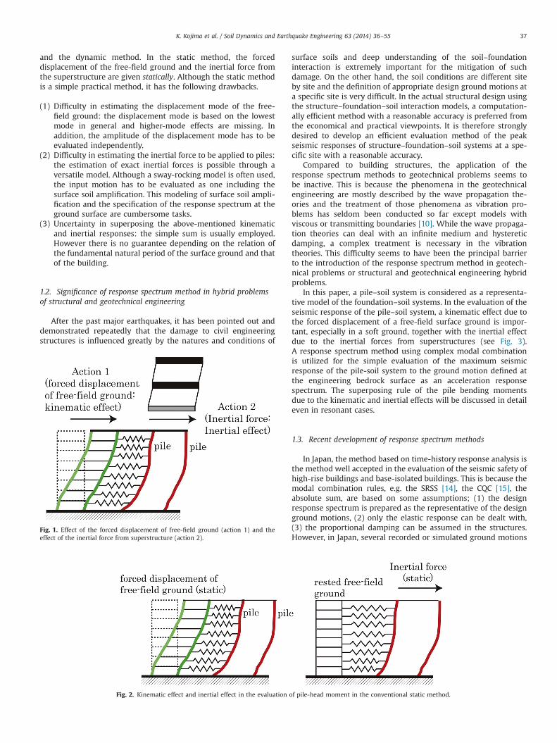
and the dynamic method. In the static method, the forceddisplacement of the free-field ground and the inertial force fromthe superstructure are given statically. Although the static methodis a simple practical method, it has the following drawbacks.
(1) Difficulty in estimating the displacement mode of the free-field ground: the displacement mode is based on the lowestmode in general and higher-mode effects are missing. Inaddition, the amplitude of the displacement mode has to beevaluated independently.
(2) Difficulty in estimating the inertial force to be applied to piles:the estimation of exact inertial forces is possible through aversatile model. Although a sway-rocking model is often used,the input motion has to be evaluated as one including thesurface soil amplification. This modeling of surface soil ampli-fication and the specification of the response spectrum at theground surface are cumbersome tasks.
(3) Uncertainty in superposing the above-mentioned kinematicand inertial responses: the simple sum is usually employed.However there is no guarantee depending on the relation ofthe fundamental natural period of the surface ground and thatof the building.
1.2. Significance of response spectrum method in hybrid problemsof structural and geotechnical engineering
After the past major earthquakes, it has been pointed out anddemonstrated repeatedly that the damage to civil engineeringstructures is influenced greatly by the natures and conditions of
surface soils and deep understanding of the soil–foundationinteraction is extremely important for the mitigation of suchdamage. On the other hand, the soil conditions are different siteby site and the definition of appropriate design ground motions ata specific site is very difficult. In the actual structural design usingthe structure–foundation–soil interaction models, a computation-ally efficient method with a reasonable accuracy is preferred fromthe economical and practical viewpoints. It is therefore stronglydesired to develop an efficient evaluation method of the peakseismic responses of structure–foundation–soil systems at a spe-cific site with a reasonable accuracy.
Compared to building structures, the application of theresponse spectrum methods to geotechnical problems seems tobe inactive. This is because the phenomena in the geotechnicalengineering are mostly described by the wave propagation the-ories and the treatment of those phenomena as vibration pro-blems has seldom been conducted so far except models withviscous or transmitting boundaries [10]. While the wave propaga-tion theories can deal with an infinite medium and hystereticdamping, a complex treatment is necessary in the vibrationtheories. This difficulty seems to have been the principal barrierto the introduction of the response spectrum method in geotech-nical problems or structural and geotechnical engineering hybridproblems.
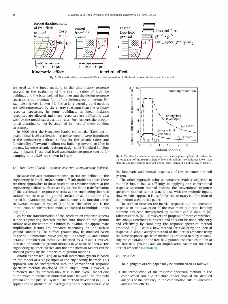
In this paper, a pile–soil system is considered as a representa-tive model of the foundation–soil systems. In the evaluation of theseismic response of the pile–soil system, a kinematic effect due tothe forced displacement of a free-field surface ground is impor-tant, especially in a soft ground, together with the inertial effectdue to the inertial forces from superstructures (see Fig. 3).A response spectrum method using complex modal combinationis utilized for the simple evaluation of the maximum seismicresponse of the pile-soil system to the ground motion defined atthe engineering bedrock surface as an acceleration responsespectrum. The superposing rule of the pile bending momentsdue to the kinematic and inertial effects will be discussed in detaileven in resonant cases.
1.3. Recent development of response spectrum methods
In Japan, the method based on time-history response analysis isthe method well accepted in the evaluation of the seismic safety ofhigh-rise buildings and base-isolated buildings. This is because themodal combination rules, e.g. the SRSS [14], the CQC [15], theabsolute sum, are based on some assumptions; (1) the designresponse spectrum is prepared as the representative of the designground motions, (2) only the elastic response can be dealt with,(3) the proportional damping can be assumed in the structures.However, in Japan, several recorded or simulated ground motions
Fig. 1. Effect of the forced displacement of free-field ground (action 1) and theeffect of the inertial force from superstructure (action 2).
Fig. 2. Kinematic effect and inertial effect in the evaluation of pile-head moment in the conventional static method.
K. Kojima et al. / Soil Dynamics and Earthquake Engineering 63 (2014) 36–55 37
are used as the input motions in the time-history responseanalysis in the evaluation of the seismic safety of high-risebuildings and the base-isolated buildings and the design responsespectrum is not a unique form of the design ground motions. Forexample, it is well-known [16,17] that long-period ground motionsare well represented by the energy spectrum than the ordinaryresponse spectrum. In some buildings, nonlinear inelasticresponses are allowed and these responses are difficult to dealwith by the modal superposition rules. Furthermore, the propor-tional damping cannot be assumed in most of these buildingstructures.
In 2000 after the Hyogoken-Nanbu earthquake (Kobe earth-quake), dual level acceleration response spectra were introducedat the engineering bedrock surface for the seismic safety andfunctionality of low and medium-rise buildings lower than 60 m inthe new Japanese seismic-resistant design code (Standard BuildingLaw in Japan). Those dual level acceleration response spectra fordamping ratio¼0.05 are shown in Fig. 4.
1.4. Treatment of design response spectrum at engineering bedrock
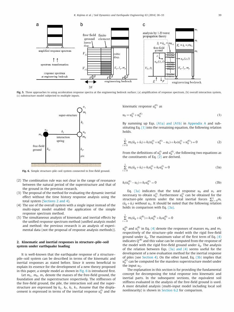
Because the acceleration response spectra are defined at theengineering bedrock surface, some difficult problems arise. Thereare three approaches to these acceleration response spectra at theengineering bedrock surface (see Fig. 5). One is the transformationof the acceleration response spectra at the engineering bedrocksurface into those at the ground surface or at the bottom of aburied foundation (Fig. 5(a)) and another one is the introduction ofan overall interaction system (Fig. 5(b)). The other one is theintroduction of substructure models subjected to multiple inputs(Fig. 5(c)).
As for the transformation of the acceleration response spectraat the engineering bedrock surface into those at the groundsurface or at the bottom of a buried foundation, the approximateamplification factors are prepared depending on the surfaceground conditions. The surface ground may be modeled basedon the one-dimensional wave propagation theory [18] and a moredetailed amplification factor can be used as a result. However,recorded or simulated ground motions have to be defined at theengineering bedrock surface and the amplification factors can beaffected greatly by the properties of ground motions.
Another approach using an overall interaction system is basedon the model of a single input at the engineering bedrock. Thisapproach can be incorporated into the conventional responsespectrum method developed for a single input. However, anumerical stability problem may arise in this overall model dueto the much difference in numerical order between the free-fieldground and the pile–soil system. The method developed in [10] isapplied to the problem for investigating the superposition rule of
the kinematic and inertial responses of the structure–pile–soilsystem.
The other approach using substructure models subjected tomultiple inputs has a difficulty in applying the conventionalresponse spectrum method because the conventional responsespectrum method cannot usually deal with the multiple inputs.However this approach is useful for the accuracy confirmation ofthe method used in this paper.
The relation between the inertial response and the kinematicresponse in the evaluation of the maximum pile-head bendingmoment has been investigated by Murono and Nishimura [6],Tokimatsu et al. [8,9]. However the proposal of more comprehen-sive analysis methods is desired and this can be done efficientlyand effectively by combining the response spectrum methodproposed in [10] with a new method for evaluating the inertialresponse. A simple analysis method of the inertial response usingthe same response spectrum method is proposed here by introdu-cing the constraint on the free-field ground (the fixed condition ofthe free-field ground) and an amplification factor for the totalinertial response (Section 4).
1.5. Novelties
The highlights of this paper may be summarized as follows:
(1) The introduction of the response spectrum method in thecomplicated soil–pile–structure model enabled the detailedanalysis of the accuracy in the combination rule of kinematicand inertial effects.
Fig. 3. Kinematic effect and inertial effect in the evaluation of pile-head moment in the dynamic method.
0
2
4
6
8
10
0 0.5 1 1.5 2 2.5 3natural period(s)
acce
lera
tion
resp
onse
spe
ctru
m(m
/s2 )
damping ratio=0.05
damage limit level input
safety limit level input
SA =1.024/T
T
0.640.16
5.12/AS =
Fig. 4. Two-level acceleration response spectra at engineering bedrock surface forthe evaluation of the seismic safety of low and medium-rise buildings lower than60 m in Japanese seismic-resistant design code (Standard Building Law in Japan).
K. Kojima et al. / Soil Dynamics and Earthquake Engineering 63 (2014) 36–5538
(2) The combination rule was not clear in the range of resonancebetween the natural period of the superstructure and that ofthe ground in the previous research.
(3) The proposal of the method for evaluating the dynamic inertialeffect without the time history response analysis using thetotal system (Sections 2 and 4).
(4) The use of the overall system with a single input instead of themulti-input model enabled the application of the simpleresponse spectrum method.
(5) The simultaneous analysis of kinematic and inertial effects bythe unified response spectrum method (unified analysis modeland method: the previous research is an analysis of experi-mental data (not the proposal of response analysis methods)).
2. Kinematic and inertial responses in structure–pile–soilsystem under earthquake loading
It is well-known that the earthquake response of a structure–pile–soil system can be described in terms of the kinematic andinertial responses as stated before. Since it seems beneficial toexplain its essence for the development of a new theory proposedin this paper, a simple model as shown in Fig. 6 is introduced first.
Let mG; m0; m1 denote the masses of the free-field ground, thefoundation and the superstructure respectively. The stiffnesses ofthe free-field ground, the pile, the interaction soil and the super-structure are expressed by kG; kP ; kI ; k1. Assume that the displa-cement is expressed in terms of the inertial response uðIÞ
0 and the
kinematic response uðKÞ0 as
u0 ¼ uðIÞ0 þuðKÞ
0 ð1Þ
By summing up Eqs. (A1a) and (A1b) in Appendix A and sub-stituting Eq. (1) into the remaining equation, the following relationholds.
∑1
i ¼ 0mið €ugþ €uiÞþkIðuðIÞ
0 þuðKÞ0 �uGÞþkPðuðIÞ
0 þuðKÞ0 Þ ¼ 0 ð2Þ
From the definitions of uðIÞ0 and uðKÞ
0 , the following two equations asthe constituents of Eq. (2) are derived.
∑1
i ¼ 0mið €ugþ €uiÞþkIu
ðIÞ0 þkPu
ðIÞ0 ¼ 0 ð3aÞ
kIðuðKÞ0 �uGÞþkPu
ðKÞ0 ¼ 0 ð3bÞ
Eq. (3a) indicates that the total response u0 and u1 arenecessary to obtain uðIÞ
0 . Furthermore uðIÞ0 can be obtained for the
structure-pile system under the total inertial forces ∑1i ¼ 0mi
ð €ugþ €uiÞ without uG. It should be noted that the following relationholds in comparison with Eq. (3a).
∑1
i ¼ 0mið €ugþ €uðRÞ
i ÞþkIuðRÞ0 þkPu
ðRÞ0 ¼ 0 ð4Þ
uðRÞ0 and uðRÞ
1 in Eq. (4) denote the responses of masses m0 and m1
respectively of the structure–pile model with the rigid free-fieldground under €ug . The maximum value of the first term of Eq. (4)indicates Q ðRÞ and this value can be computed from the response ofthe model with the rigid free-field ground under €ug . The analysisof the relation between Eqs. (3a) and (4) seems useful for thedevelopment of a new evaluation method for the inertial responseof piles (see Section 4). On the other hand, Eq. (3b) implies thatuðKÞ0 can be computed for the massless superstructure model under
the input uG.The explanation in this section is for providing the fundamental
concept for decomposing the total response into kinematic andinertial parts. In the subsequent sections, the equivalent soilstiffness evaluated in the analysis of the free-field ground is used.A more detailed analysis (multi-input model including local soilnonlinearity) is shown in Section 6.2 for comparison.
Fig. 5. Three approaches to using acceleration response spectra at the engineering bedrock surface; (a) amplification of response spectrum, (b) overall interaction system,(c) substructure model subjected to multiple inputs.
GmGu
Gk
Ik
Pk
1k
1m
0m0u
1u
free-field ground
pile
super-structure
interaction spring
Fig. 6. Simple structure–pile–soil system connected to free-field ground.
K. Kojima et al. / Soil Dynamics and Earthquake Engineering 63 (2014) 36–55 39
3. Response spectrum method for free-field ground andstructure–pile–soil system
3.1. Ground model
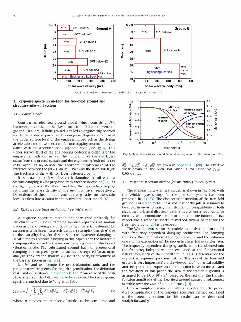
Consider an idealized ground model which consists of N-1homogeneous horizontal soil layers on semi-infinite homogeneousground. This semi-infinite ground is called an engineering bedrockfor structural design purposes. The design earthquake is defined atthe upper surface level of the engineering bedrock as the designacceleration response spectrum for outcropping motion in accor-dance with the aforementioned Japanese code (see Fig. 4). Thisupper surface level of the engineering bedrock is called later theengineering bedrock surface. The numbering of the soil layersstarts from the ground surface and the engineering bedrock is theN-th layer. Let um denote the horizontal displacement of theinterface between the ðm�1Þ-th soil layer and the m-th soil layer.The thickness of the m-th soil layer is denoted by hm.
It is usual to employ a hysteretic damping in soil while aviscous damping is also proposed from another viewpoint [19]. LetGm; βm; ρm denote the shear modulus, the hysteretic dampingratio and the mass density of the m-th soil layer, respectively.Dependence of shear moduli and damping ratios on the strainlevel is taken into account in the equivalent linear model [18].
3.2. Response spectrum method for free-field ground
A response spectrum method has been used primarily forstructures with viscous damping because equations of motionunder arbitrary loading are difficult to describe in time domain forstructures with linear hysteretic damping (complex damping) dueto the causality law. For this reason, the hysteretic damping issubstituted by a viscous damping in this paper. Then the hystereticdamping ratio is used as the viscous damping ratio for the lowestvibration mode. The substituted ground has non-proportionaldamping and complex eigenvalue analysis is required for accurateanalysis. For vibration analysis, a viscous boundary is introduced atthe base as shown in Fig. 5(b).
Let hðjÞ and ωðjÞ denote the pseudodamping ratio and thepseudonatural frequency for the j-th eigenvibration. The definitionof hðjÞ and ωðjÞ is shown in Appendix B. The mean value of the peakshear strains in the k-th layer may be evaluated by the responsespectrum method due to Yang et al. [20].
γk max ¼1hk
ffiffiffiffiffiffiffiffiffiffiffiffiffiffiffiffiffiffiffiffiffiffiffiffiffiffiffiffiffiffiffiffiffiffiffiffiffiffiffiffiffiffiffiffiffiffiffiffiffiffiffiffiffiffiffiffiffiffiffiffiffiffiffiffiffiffiffiffiffiffiffiffiffiffiffiffiffiffiffiffiffiffiffiffiffiffiffiffiffiffiffi∑n
i ¼ 1∑n
j ¼ 1fδðiÞskρðijÞ
ss δðjÞskþ2δðiÞskρ
ðijÞsc δ
ðjÞckþδðiÞckρ
ðijÞcc δ
ðjÞckg
s; ð5Þ
where n denotes the number of modes to be considered and
δðiÞsk ; δðiÞck; ρ
ðijÞss ; ρ
ðijÞcc ; ρ
ðijÞsc are given in Appendix B [20]. The effective
shear strain in the k-th soil layer is evaluated by γk eff ¼0:65� γk max.
3.3. Response spectrum method for structure–pile–soil system
The efficient finite-element model, as shown in Fig. 5(b), withthe Winkler-type springs for the pile–soil systems has beenproposed in [21–23]. The displacement function of the free-fieldground is assumed to be linear and that of the pile is assumed tobe cubic. In order to satisfy the deformation compatibility at bothsides, the horizontal displacement in this element is required to becubic. Viscous boundaries are incorporated at the bottom of thatmodel and a response spectrum method similar to that for thefree-field ground [24] is developed.
The Winkler-type spring is modeled as a dynamic spring [1]with frequency dependent damping coefficients. The dampingratios are the combination of the hysteretic one and the radiationone and the expression will be shown in numerical examples later.The frequency-dependent damping coefficient is transformed intothe frequency-independent one evaluated at the fundamentalnatural frequency of the superstructure. This is essential for theuse of the response spectrum method. The area of the free-fieldground is very important from the viewpoint of numerical stabilityand the appropriate expression of interaction between the pile andthe free-field. In this paper, the area of the free-field ground isassumed to be 1:0� 106 ðm2Þ based on the fact that the transferfunction amplitude of the free-field ground surface displacementis stable over the area of 1:0� 105 ðm2Þ [10].
Once a complex eigenvalue analysis is performed, the proce-dure of application of the response spectrum method explainedin the foregoing section to this model can be developedstraightforwardly.
0
5
10
15
20
25
30
35
40
shear wave velocity (m/s)
Dep
th (m
)
GL-sand
sand
clay
clay
sand
clay
clay Engineering Bedrock
SPT value=2
SPT value=3
SPT value=4
SPT value=2
SPT value=22
SPT value=3SPT value=44
0 100 200 300 400 500 0 100 200 300 400 500
0
5
10
15
20
25
30
35
40
shear wave velocity (m/s)
Dep
th (m
)
GL-
clay
sand
clayEngineering Bedrock
SPT value=6
SPT value=14
SPT value=66
Ground A Ground B
Fig. 7. Soil profiles of two ground models A and B and SPT values [10].
0
0.2
0.4
0.6
0.8
1
1.2
0
0.05
0.1
0.15
0.2
0.25
0.3
0.35
0.4
10-6 10-5 10-4 10-3 10-2 10-1
shear strain
stiffnessof clay
stiffnessof sand
damping ratioof sand
damping ratioof clay
stiff
ness
redu
ctio
n ra
tio G
/G0
dam
ping
ratio
β
Fig. 8. Dependence of shear moduli and damping ratios on the strain level [24].
K. Kojima et al. / Soil Dynamics and Earthquake Engineering 63 (2014) 36–5540
The element stiffness matrix for the interaction springs can befound in [21,22]. The corresponding element damping matrix forthe interaction dashpots has been taken into account. The con-sistent masses of the free-field ground and the pile have beenconsidered.
The mean value of the maximum bending moment and shearforce at the pile head may be evaluated by
Mmax ¼ffiffiffiffiffiffiffiffiffiffiffiffiffiffiffiffiffiffiffiffiffiffiffiffiffiffiffiffiffiffiffiffiffiffiffiffiffiffiffiffiffiffiffiffiffiffiffiffiffiffiffiffiffiffiffiffiffiffiffiffiffiffiffiffiffiffiffiffiffiffiffiffiffiffiffiffiffiffiffiffiffiffiffiffiffiffiffiffiffiffiffiffiffiffiffi∑n
i ¼ 1∑n
j ¼ 1ZðiÞs ρ
ðijÞss Z
ðjÞs þ2ZðiÞ
s ρðijÞsc Z
ðjÞc þZðiÞ
c ρðijÞcc Z
ðjÞc
n osð6Þ
Qmax ¼ffiffiffiffiffiffiffiffiffiffiffiffiffiffiffiffiffiffiffiffiffiffiffiffiffiffiffiffiffiffiffiffiffiffiffiffiffiffiffiffiffiffiffiffiffiffiffiffiffiffiffiffiffiffiffiffiffiffiffiffiffiffiffiffiffiffiffiffiffiffiffiffiffiffiffiffiffiffiffiffiffiffiffiffiffiffiffiffiffiffiffiffiffiffiffiffiffi∑n
i ¼ 1∑n
j ¼ 1Y ðiÞs ρ
ðijÞss Y
ðjÞs þ2Y ðiÞ
s ρðijÞsc Y
ðjÞc þY ðiÞ
c ρðijÞcc Y
ðjÞc
n osð7Þ
where
ZðiÞs ¼ EI � SðiÞDsRe½νðiÞκðiÞ�; ZðiÞ
c ¼ EI � SðiÞDcRe½νðiÞκðiÞ� ð8a;bÞ
Y ðiÞs ¼ EI � SðiÞDsRe½νðiÞζ
ðiÞ�; Y ðiÞc ¼ EI � SðiÞDcRe½νðiÞζ
ðiÞ� ð9a;bÞ
In Eqs. (8) and (9), EI is the bending stiffness of the pile and κðiÞ isthe curvature component at the pile head in the i-th complexeigenmode. ζðiÞ is the derivative of the curvature component withrespect to the pile axial coordinate at the pile head in the i-thcomplex eigenmode.
In order to investigate the accuracy of the present methodusing the dynamic Winkler-type spring, a single pile of dia-meter¼1.0 (m) and length¼20 (m) in a homogeneous semi-infinite ground of shear wave velocity¼100 (m/s) and dampingratio¼0.05 has been analyzed in [10]. It has been demonstratedthrough the comparison with the thin-layer method [25–27] thatthe present method using the dynamic Winkler-type spring has areasonable accuracy.
In addition, for investigating the accuracy of the presentmethod, the comparison with the continuum model [23] has beenmade. A two-story shear building model on a surface ground oftwo soil layers (depth of each soil layer¼10 (m), shear wavevelocity¼100 (m/s), 200 (m/s) from the top, pile diameter¼1.5(m)) has been analyzed in [10]. It has been disclosed that a fairlygood correspondence can be seen in the case of using the Rayleighdamping and this supports clearly the validity of the presentFEM model.
3.4. Extraction of kinematic response
The kinematic response of the pile-head bending moment dueto the forced displacement of the free-field ground under noinertial force from the super-structure can be evaluated byspecifying the zero masses in the super-structure and foundationas explained in Section 2 (see Fig. 3). The same analysis modelexcept these zero masses and the same analysis method (responsespectrum method) can be used.
4. Evaluation of inertial response
The inertial response can be evaluated conventionally by thepile-head shear force Qtotal from the total response and the staticresponse under this pile-head shear force at the rest of the free-field ground (no deformation of free-field ground). Although thestatic response is one possibility (see Fig. 2) and may causedifficulties stated in Section 1.1.2, another method can be devised.If the same response spectrum method used for the total responseand the kinematic response is available, it may be desirable.
Let Qrigid and Mrigid denote the maximum dynamic pile-headshear force and bending moment of the model with the rigid free-field ground under a response spectrum at the engineering bed-rock. It is assumed here that the shear force and bending momentdistributions of a pile in an inertial response are proportional tothose of the model with the rigid free-field ground under aresponse spectrum at the engineering bedrock. This is because,(1) the boundary condition are the same between the inertialresponse case (a static shear force at the pile head for a rigid free-field ground) and the model with the rigid free-field ground undera response spectrum at the engineering bedrock, (2) the pileinertial force effect is negligible in the model with the rigid free-field ground under a response spectrum at the engineering bed-rock and (3) the pile bending moment in the inertial response isconcentrated to the narrow range near the pile head. This issuehas also been discussed in Section 2. Since Q ðKÞffi0 andQtotalffiQ ðIÞ, the inertial response (see Fig. 3) of the pile-headbending moment may be evaluated by
MðIÞ ¼MrigidðQtotal=QrigidÞ ð10ÞThis relation has been validated from the fact that the sum ofthe super-structure inertial forces in the total response is
0
5
10
15
20
25
30
35
40
damage limit level/stiffness ratio(spectrum method)damage limit level/stiffness ratio(SHAKE)
G/G 0
dept
h (m
)
0 0.2 0.4 0.6 0.8 1 0 0.2 0.4 0.6 0.8 1
0
5
10
15
20
25
30
35
damage limit level/stiffness ratio(spectrum method)damage limit level/stiffness ratio (SHAKE)
G/G 0
dept
h (m
)
Ground A Ground B
Fig. 9. Convergent shear modulus ratio to the initial one (damage limit level): response spectrum method and SHAKE for one simulated motion [24].
K. Kojima et al. / Soil Dynamics and Earthquake Engineering 63 (2014) 36–55 41
approximately equal to the inertial one ðQtotalffiQ ðIÞÞ and that theshear force and bending moment distributions of a pile in aninertial response are proportional to those of the model with therigid free-field ground under a response spectrum at the engineer-ing bedrock due to the above-mentioned reasons.
5. Numerical examples
5.1. Design earthquakes at engineering bedrock surface
The design earthquake ground motion mentioned in Section 1.3is employed here. In the seismic-resistant design code, elasticdesign is required for the damage-limit level motion (the max-imum spectral acceleration for damping ratio 0.05 defined for theengineering bedrock surface motion as outcropping motion is 1.6(m/s2)) and inelastic design is allowed for the safety-limit levelmotion (the maximum spectral acceleration for damping ratio 0.05is 8 (m/s2)). The design acceleration response spectrum SA (in m/s2
for damping ratio 0.05) in terms of natural period T for thedamage-limit level motion may be expressed as
SA ¼ 0:64þ6:0T ðTo0:16 sÞSA ¼ 1:6 ð0:16 srTr0:64 sÞSA ¼ 1:024=T ð0:64 soTÞ ð11Þ
The design acceleration response spectrum for the safety-limitlevel motion can be expressed by multiplying Eq. (11) by five. Thisdesign acceleration response spectrum SA for the damage-limitlevel motion and that for the safety-limit level motion are shownin Fig. 4. This spectrum has a tendency similar to the conventionalone [28], i.e. the constant acceleration region and the constantvelocity region exist. As the amplification factors from the max-imum acceleration and velocity of the input in terms of dampingratios, those (median type) proposed in [28] are used.
5.2. Two ground models: soft and stiff ground models
Two surface ground models, referred to as ground model A(rather soft ground) and ground model B (slightly stiff ground),are considered. The soil profiles of these two ground models areshown in Fig. 7. The SPT values in the soil layers for ground modelsA and B are also shown for reference. The mass density of surfacesoil layers is assumed to be 1:8� 103 ðkg=m3Þ and Poisson's ratio is0.45. The ground model A consists of six soil layers on theengineering bedrock (the mass density is assumed to be2:0� 103 ðkg=m3Þ) and the ground model B consists of two soillayers on the engineering bedrock. In both ground models, eachsoil layer has been divided into sub-layers of thickness of 1 (m). Asa result, the ground model A consists of 38 sub-layers and theground model B consists of 30 sub-layers.
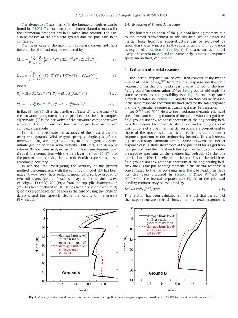
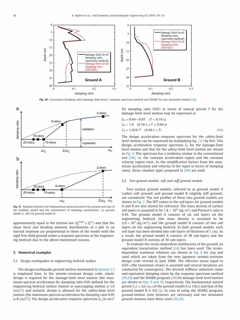
To evaluate the strain-dependent nonlinearity of the ground, anequivalent linearization method [24] has been used. The strain-dependent nonlinear relations are shown in Fig. 8 for clay andsand which are taken from the new Japanese seismic-resistantdesign code revised in June 2000. The effective strain equal to0.65�(the maximum strain) is assumed and several iterations areconducted for convergence. The derived stiffness reduction ratiosand equivalent damping ratios by the response spectrum method[10,24] and the SHAKE program [18] for damage-limit level motionare shown in Figs. 9 and 10, respectively. The fundamental naturalperiod TGð ¼ 2π=ωGÞ of the ground model A is 1.0(s) and that of theground model B is 0.6 (s). In case of using the SHAKE program,ground-motion time histories are necessary and ten simulatedground motions have been used [10,24].
0
5
10
15
20
25
30
35
40
damage limit level/damping ratio (spectrum method)damage limit level/damping ratio (SHAKE)
damping ratio
dept
h (m
)
0 0.1 0.2 0.3 0 0.1 0.2 0.3
0
5
10
15
20
25
30
35
damage limit level/damping ratio (spectrum method)damage limit level/damping ratio (SHAKE)
damping ratio
dept
h (m
)
Ground A Ground B
Fig. 10. Convergent damping ratio (damage limit level): response spectrum method and SHAKE for one simulated motion [24].
dam
ping
ratio
dam
ping
ratio
2-story
2-story
6-story
6-story
10-story
10-story
16-story
16-story
20-story
20-story
radiation
hysteretic
Fig. 11. Relation between the fundamental natural period of the ground and that ofthe building model and the constituents of damping mechanisms: (a) groundmodel A, and (b) ground model B.
K. Kojima et al. / Soil Dynamics and Earthquake Engineering 63 (2014) 36–5542
The damping ratios derived here are substituted into the termof the hysteretic damping β and the following radiation dampingis added to those ones [1,2].
cx ¼2kxωG
ω1dρsVs
kx1þ Vc
Vs
� �54
" #ω1dVs
� �� 14
þβ
( )ðω1Z2ωGÞ ð12Þ
In Eq. (12), cx, d, ρs, Vs, Vc , kx, ω1 are the damping coefficient of theinteraction dashpot, the pile diameter, the soil mass density, thesoil shear velocity, the Lysmer's analog velocity (¼Vs here),the Winkler-type stiffness of the interaction spring (strain-depen-dent equivalent one), the fundamental natural circular frequencyof the superstructure. The radiation damping ratio is zero in
ω1rωG and is linear in ωGrω1r2ωG. The final damping ratioat each soil layer is evaluated at the fundamental natural fre-quency of the superstructure as a frequency-independent one.These data are used in the computation of the kinematic effect, theinertial effect and the total response. From Figs. 9 and 10, it can beseen that the present response spectrum method has a reasonableaccuracy compared with the SHAKE program.
The accuracy of the response spectrum method has beendemonstrated by the senior author for the total model includingthe kinematic and inertial effects simultaneously in terms of thetransfer functions [10]. A Winkler-type continuum model has beenused as another model for comparison [10]. Another comparisonhas been made with an actual record and the present method has
0
5
10
15
20
25
30
35
400 2 105 4 105 6 105 8 105
kinematictotalinertial
bending moment (Nm)
dept
h (m
)
2-story (Ground A)
0
5
10
15
20
25
300 2 105 4 105 6 105 8 105
kinematictotalinertial
bending moment (Nm)
dept
h (m
)
2-story (Ground B)
0
5
10
15
20
25
30
35
400 2 105 4 105 6 105 8 105
kinematictotalinertial
bending moment (Nm)
dept
h (m
)
6-story (Ground A)
0
5
10
15
20
25
300 2 105 4 105 6 105 8 105
kinematictotalinertial
bending moment (Nm)
dept
h (m
)
6-story (Ground B)
0
5
10
15
20
25
30
35
400 2 105 4 105 6 105 8 105
kinematictotalinertial
bending moment (Nm)
dept
h (m
)
10-story (Ground A)
0
5
10
15
20
25
300 2 105 4 105 6 105 8 105
kinematictotalinertial
bending moment (Nm)
dept
h (m
)
10-story (Ground B)
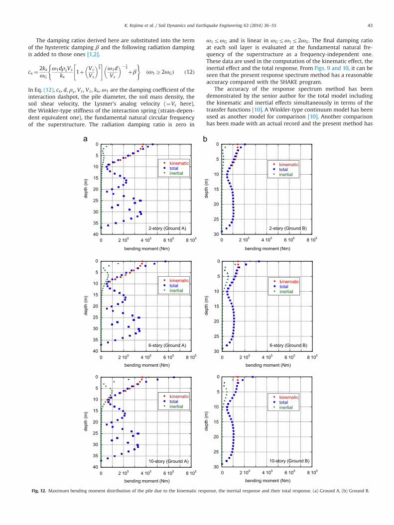
Fig. 12. Maximum bending moment distribution of the pile due to the kinematic response, the inertial response and their total response. (a) Ground A, (b) Ground B.
K. Kojima et al. / Soil Dynamics and Earthquake Engineering 63 (2014) 36–55 43
been proven to be accurate enough when taking into account thestrain-amplitude nonlinearity of soil deposit [23].
It has been understood that, by the use of the responsespectrum method, these distributions of shear forces and bendingmoments in piles in the analysis of the kinematic interaction canbe obtained efficiently. Although the response spectrum methodhas been developed in the analysis of the kinematic interactiononly and the overall system including both the kinematic andinertial interactions [10], it has been extended in this paper to thecase including the inertial interaction only.
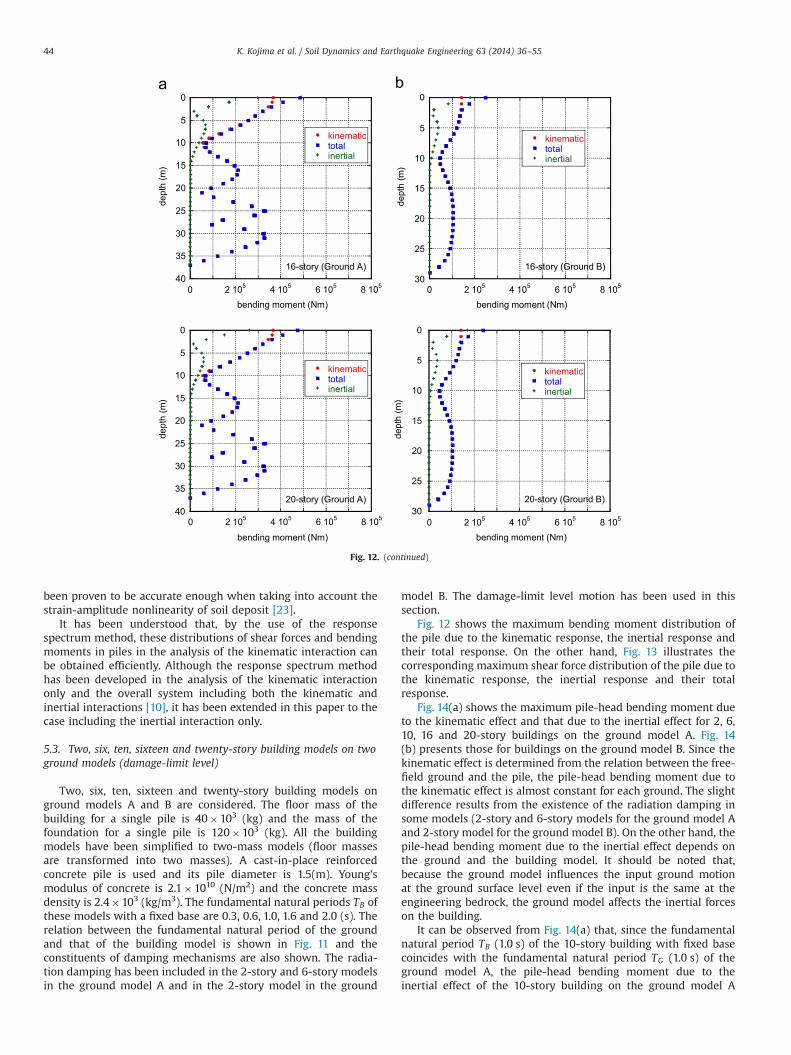
5.3. Two, six, ten, sixteen and twenty-story building models on twoground models (damage-limit level)
Two, six, ten, sixteen and twenty-story building models onground models A and B are considered. The floor mass of thebuilding for a single pile is 40�103 (kg) and the mass of thefoundation for a single pile is 120�103 (kg). All the buildingmodels have been simplified to two-mass models (floor massesare transformed into two masses). A cast-in-place reinforcedconcrete pile is used and its pile diameter is 1.5(m). Young'smodulus of concrete is 2.1�1010 (N/m2) and the concrete massdensity is 2.4�103 (kg/m3). The fundamental natural periods TB ofthese models with a fixed base are 0.3, 0.6, 1.0, 1.6 and 2.0 (s). Therelation between the fundamental natural period of the groundand that of the building model is shown in Fig. 11 and theconstituents of damping mechanisms are also shown. The radia-tion damping has been included in the 2-story and 6-story modelsin the ground model A and in the 2-story model in the ground
model B. The damage-limit level motion has been used in thissection.
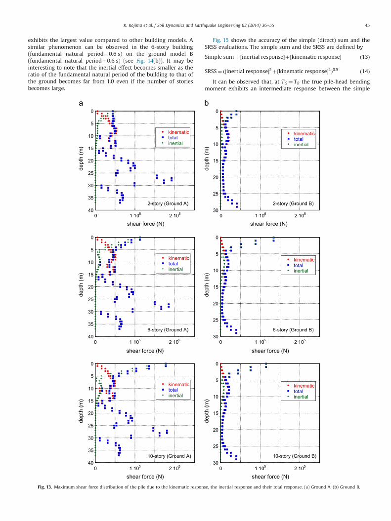
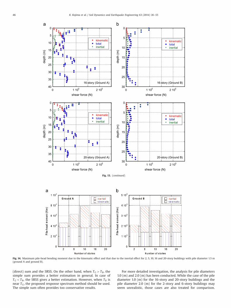
Fig. 12 shows the maximum bending moment distribution ofthe pile due to the kinematic response, the inertial response andtheir total response. On the other hand, Fig. 13 illustrates thecorresponding maximum shear force distribution of the pile due tothe kinematic response, the inertial response and their totalresponse.
Fig. 14(a) shows the maximum pile-head bending moment dueto the kinematic effect and that due to the inertial effect for 2, 6,10, 16 and 20-story buildings on the ground model A. Fig. 14(b) presents those for buildings on the ground model B. Since thekinematic effect is determined from the relation between the free-field ground and the pile, the pile-head bending moment due tothe kinematic effect is almost constant for each ground. The slightdifference results from the existence of the radiation damping insome models (2-story and 6-story models for the ground model Aand 2-story model for the ground model B). On the other hand, thepile-head bending moment due to the inertial effect depends onthe ground and the building model. It should be noted that,because the ground model influences the input ground motionat the ground surface level even if the input is the same at theengineering bedrock, the ground model affects the inertial forceson the building.
It can be observed from Fig. 14(a) that, since the fundamentalnatural period TB (1.0 s) of the 10-story building with fixed basecoincides with the fundamental natural period TG (1.0 s) of theground model A, the pile-head bending moment due to theinertial effect of the 10-story building on the ground model A
0
5
10
15
20
25
30
35
400 2 105 4 105 6 105 8 105
kinematictotalinertial
bending moment (Nm)
dept
h (m
)
16-story (Ground A)
0
5
10
15
20
25
300 2 105 4 105 6 105 8 105
kinematictotalinertial
bending moment (Nm)
dept
h (m
)
16-story (Ground B)
0
5
10
15
20
25
30
35
400 2 105 4 105 6 105 8 105
kinematictotalinertial
bending moment (Nm)
dept
h (m
)
20-story (Ground A)
0
5
10
15
20
25
300 2 105 4 105 6 105 8 105
kinematictotalinertial
bending moment (Nm)
dept
h (m
)
20-story (Ground B)
Fig. 12. (continued)
K. Kojima et al. / Soil Dynamics and Earthquake Engineering 63 (2014) 36–5544
exhibits the largest value compared to other building models. Asimilar phenomenon can be observed in the 6-story building(fundamental natural period¼0.6 s) on the ground model B(fundamental natural period¼0.6 s) (see Fig. 14(b)). It may beinteresting to note that the inertial effect becomes smaller as theratio of the fundamental natural period of the building to that ofthe ground becomes far from 1.0 even if the number of storiesbecomes large.
Fig. 15 shows the accuracy of the simple (direct) sum and theSRSS evaluations. The simple sum and the SRSS are defined by
Simple sum¼ ½inertial response�þ½kinematic response� ð13Þ
SRSS¼ ð½inertial response�2þ½kinematic response�2Þ0:5 ð14ÞIt can be observed that, at TG ¼ TB the true pile-head bending
moment exhibits an intermediate response between the simple
0
5
10
15
20
25
30
35
400 1 105 2 105
kinematictotalinertial
shear force (N)
dept
h (m
)
2-story (Ground A)
0
5
10
15
20
25
300 1 105 2 105
kinematictotalinertial
shear force (N)
dept
h (m
)2-story (Ground B)
0
5
10
15
20
25
30
35
400 1 105 2 105
kinematictotalinertial
shear force (N)
dept
h (m
)
6-story (Ground A)
0
5
10
15
20
25
300 1 105 2 105
kinematictotalinertial
shear force (N)
dept
h (m
)
6-story (Ground B)
0
5
10
15
20
25
30
35
400 1 105 2 105
kinematictotalinertial
shear force (N)
dept
h (m
)
10-story (Ground A)
0
5
10
15
20
25
300 1 105 2 105
kinematictotalinertial
shear force (N)
dept
h (m
)
10-story (Ground B)
Fig. 13. Maximum shear force distribution of the pile due to the kinematic response, the inertial response and their total response. (a) Ground A, (b) Ground B.
K. Kojima et al. / Soil Dynamics and Earthquake Engineering 63 (2014) 36–55 45
(direct) sum and the SRSS. On the other hand, when TG4TB, thesimple sum provides a better estimation in general. In case ofTGoTB, the SRSS gives a better estimation. However, when TB isnear TG, the proposed response spectrum method should be used.The simple sum often provides too conservative results.
For more detailed investigation, the analysis for pile diameters1.0 (m) and 2.0 (m) has been conducted. While the case of the pilediameter 1.0 (m) for the 16-story and 20-story buildings and thepile diameter 2.0 (m) for the 2-story and 6-story buildings mayseem unrealistic, those cases are also treated for comparison.
0
5
10
15
20
25
30
35
400 1 105 2 105
kinematictotalinertial
shear force (N)
dept
h (m
)
16-story (Ground A)
0
5
10
15
20
25
300 1 105 2 105
kinematictotalinertial
shear force (N)
dept
h (m
)
16-story (Ground B)
0
5
10
15
20
25
30
35
400 1 105 2 105
kinematictotalinertial
shear force (N)
dept
h (m
)
20-story (Ground A)
0
5
10
15
20
25
300 1 105 2 105
kinematictotalinertial
shear force (N)
dept
h (m
)
20-story (Ground B)
Fig. 13. (continued)
Fig. 14. Maximum pile-head bending moment due to the kinematic effect and that due to the inertial effect for 2, 5, 10, 16 and 20-story buildings with pile diameter 1.5 m(ground A and ground B).
K. Kojima et al. / Soil Dynamics and Earthquake Engineering 63 (2014) 36–5546
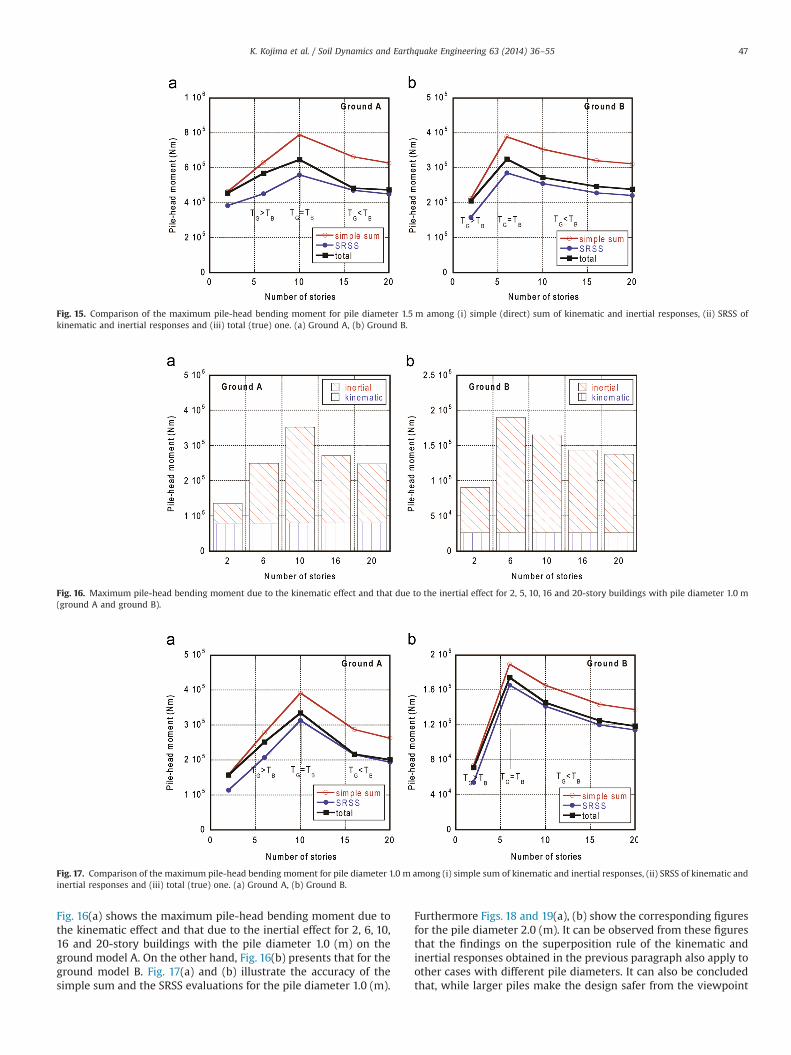
Fig. 16(a) shows the maximum pile-head bending moment due tothe kinematic effect and that due to the inertial effect for 2, 6, 10,16 and 20-story buildings with the pile diameter 1.0 (m) on theground model A. On the other hand, Fig. 16(b) presents that for theground model B. Fig. 17(a) and (b) illustrate the accuracy of thesimple sum and the SRSS evaluations for the pile diameter 1.0 (m).
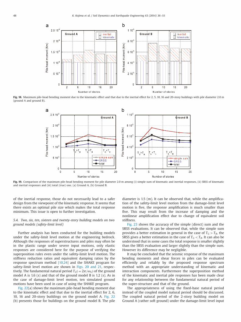
Furthermore Figs. 18 and 19(a), (b) show the corresponding figuresfor the pile diameter 2.0 (m). It can be observed from these figuresthat the findings on the superposition rule of the kinematic andinertial responses obtained in the previous paragraph also apply toother cases with different pile diameters. It can also be concludedthat, while larger piles make the design safer from the viewpoint
Fig. 15. Comparison of the maximum pile-head bending moment for pile diameter 1.5 m among (i) simple (direct) sum of kinematic and inertial responses, (ii) SRSS ofkinematic and inertial responses and (iii) total (true) one. (a) Ground A, (b) Ground B.
Fig. 16. Maximum pile-head bending moment due to the kinematic effect and that due to the inertial effect for 2, 5, 10, 16 and 20-story buildings with pile diameter 1.0 m(ground A and ground B).
Fig. 17. Comparison of the maximum pile-head bending moment for pile diameter 1.0 m among (i) simple sum of kinematic and inertial responses, (ii) SRSS of kinematic andinertial responses and (iii) total (true) one. (a) Ground A, (b) Ground B.
K. Kojima et al. / Soil Dynamics and Earthquake Engineering 63 (2014) 36–55 47
of the inertial response, those do not necessarily lead to a saferdesign from the viewpoint of the kinematic response. It seems thatthere exists an optimal pile size which makes the total responseminimum. This issue is open to further investigation.
5.4. Two, six, ten, sixteen and twenty-story building models on twoground models (safety-limit level)
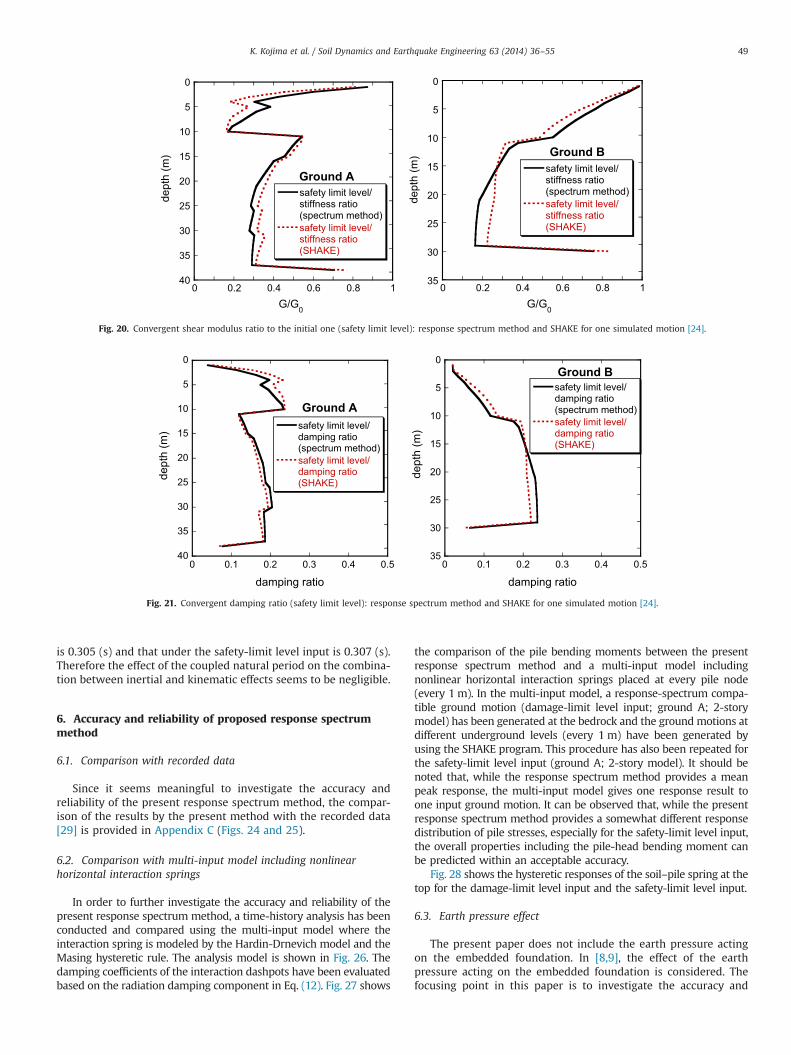
Further analysis has been conducted for the building modelsunder the safety-limit level motion at the engineering bedrock.Although the responses of superstructures and piles may often bein the plastic range under severe input motions, only elasticresponses are considered here for the purpose of verifying thesuperposition rules even under the safety-limit level motion. Thestiffness reduction ratios and equivalent damping ratios by theresponse spectrum method [10,24] and the SHAKE program forsafety-limit level motion are shown in Figs. 20 and 21, respec-tively. The fundamental natural period TGð ¼ 2π=ωGÞ of the groundmodel A is 1.6 (s) and that of the ground model B is 1.2 (s). As inthe case of damage-limit level motion, ten simulated groundmotions have been used in case of using the SHAKE program.
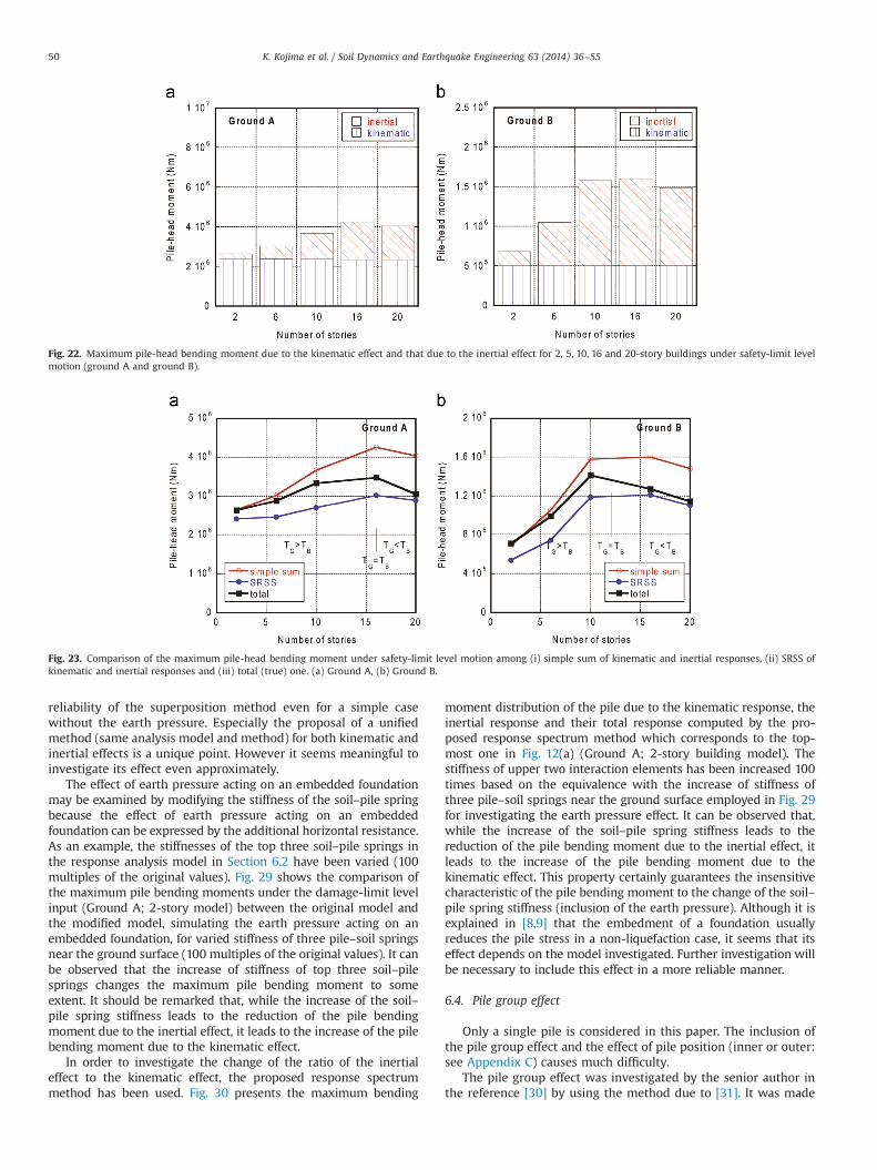
Fig. 22(a) shows the maximum pile-head bending moment dueto the kinematic effect and that due to the inertial effect for 2, 6,10, 16 and 20-story buildings on the ground model A. Fig. 22(b) presents those for buildings on the ground model B. The pile
diameter is 1.5 (m). It can be observed that, while the amplifica-tion of the safety-limit level motion from the damage-limit levelmotion is five, the response amplification is much smaller thanfive. This may result from the increase of damping and thenonlinear amplification effect due to change of equivalent soilstiffness.
Fig. 23 shows the accuracy of the simple (direct) sum and theSRSS evaluations. It can be observed that, while the simple sumprovides a better estimation in general in the case of TG4TB, theSRSS gives a better estimation in the case of TGoTB. It can also beunderstood that in some cases the total response is smaller slightlythan the SRSS evaluation and larger slightly than the simple sum.However its difference may be negligible.
It may be concluded that the seismic response of the maximumbending moments and shear forces in piles can be evaluatedefficiently and reliably by the proposed response spectrummethod with an appropriate understanding of kinematic andinteraction components. Furthermore the superposition methodof the kinematic and inertial pile responses has been made clearfor any relationship between the fundamental natural period ofthe super-structure and that of the ground.
The appropriateness of using the fixed-base natural periodinstead of the coupled model natural period should be discussed.The coupled natural period of the 2-story building model onGround A (rather soft ground) under the damage-limit level input
Fig. 18. Maximum pile-head bending moment due to the kinematic effect and that due to the inertial effect for 2, 5, 10, 16 and 20-story buildings with pile diameter 2.0 m(ground A and ground B).
Fig. 19. Comparison of the maximum pile-head bending moment for pile diameter 2.0 m among (i) simple sum of kinematic and inertial responses, (ii) SRSS of kinematicand inertial responses and (iii) total (true) one. (a) Ground A, (b) Ground B.
K. Kojima et al. / Soil Dynamics and Earthquake Engineering 63 (2014) 36–5548
is 0.305 (s) and that under the safety-limit level input is 0.307 (s).Therefore the effect of the coupled natural period on the combina-tion between inertial and kinematic effects seems to be negligible.
6. Accuracy and reliability of proposed response spectrummethod
6.1. Comparison with recorded data
Since it seems meaningful to investigate the accuracy andreliability of the present response spectrum method, the compar-ison of the results by the present method with the recorded data[29] is provided in Appendix C (Figs. 24 and 25).
6.2. Comparison with multi-input model including nonlinearhorizontal interaction springs
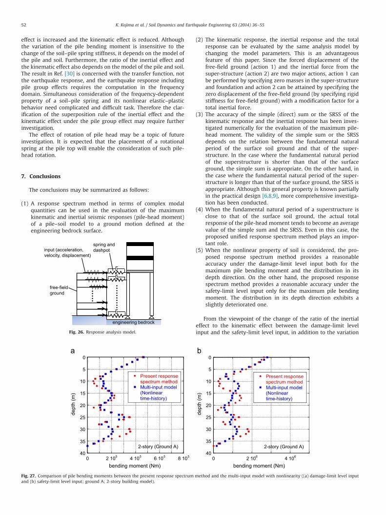
In order to further investigate the accuracy and reliability of thepresent response spectrum method, a time-history analysis has beenconducted and compared using the multi-input model where theinteraction spring is modeled by the Hardin-Drnevich model and theMasing hysteretic rule. The analysis model is shown in Fig. 26. Thedamping coefficients of the interaction dashpots have been evaluatedbased on the radiation damping component in Eq. (12). Fig. 27 shows
the comparison of the pile bending moments between the presentresponse spectrum method and a multi-input model includingnonlinear horizontal interaction springs placed at every pile node(every 1 m). In the multi-input model, a response-spectrum compa-tible ground motion (damage-limit level input; ground A; 2-storymodel) has been generated at the bedrock and the ground motions atdifferent underground levels (every 1 m) have been generated byusing the SHAKE program. This procedure has also been repeated forthe safety-limit level input (ground A; 2-story model). It should benoted that, while the response spectrum method provides a meanpeak response, the multi-input model gives one response result toone input ground motion. It can be observed that, while the presentresponse spectrum method provides a somewhat different responsedistribution of pile stresses, especially for the safety-limit level input,the overall properties including the pile-head bending moment canbe predicted within an acceptable accuracy.
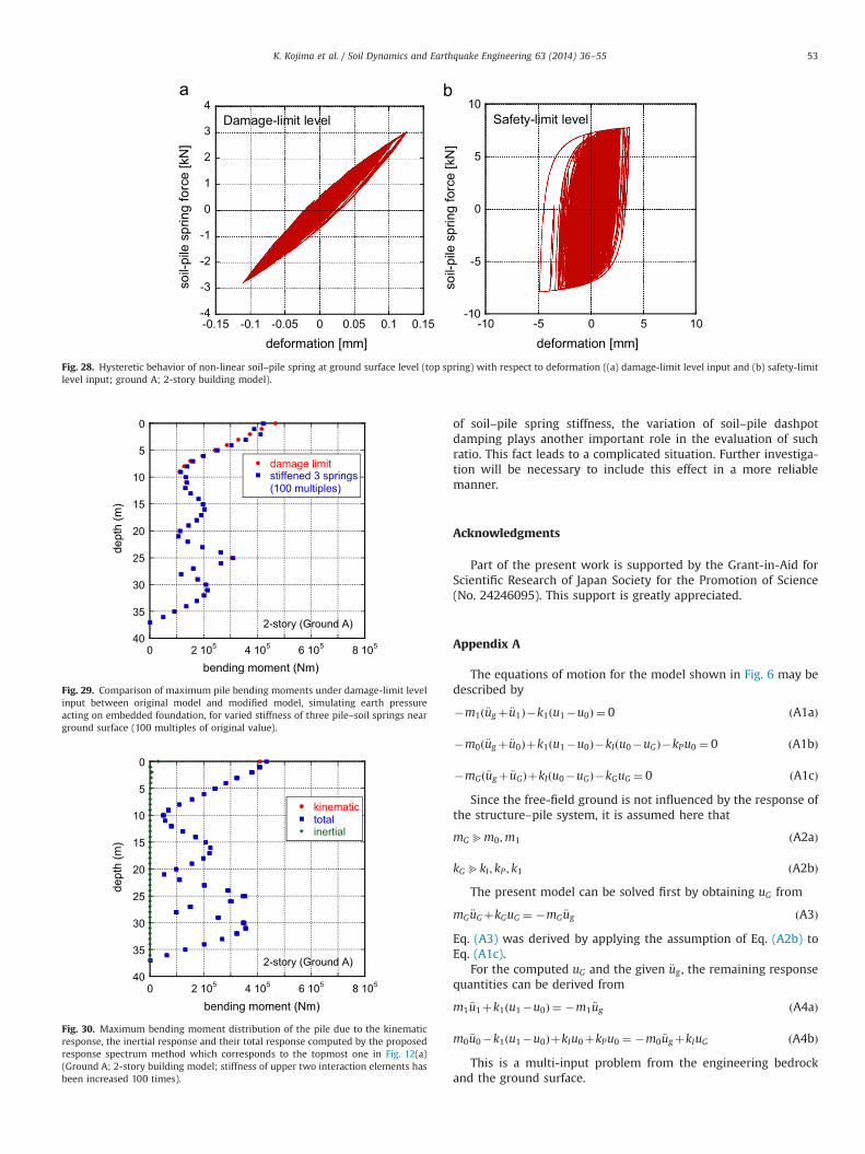
Fig. 28 shows the hysteretic responses of the soil–pile spring at thetop for the damage-limit level input and the safety-limit level input.
6.3. Earth pressure effect
The present paper does not include the earth pressure actingon the embedded foundation. In [8,9], the effect of the earthpressure acting on the embedded foundation is considered. Thefocusing point in this paper is to investigate the accuracy and
0
5
10
15
20
25
30
35
40
safety limit level/stiffness ratio(spectrum method)safety limit level/stiffness ratio(SHAKE)
G/G0
dept
h (m
)
0 0.2 0.4 0.6 0.8 1 0 0.2 0.4 0.6 0.8 1
0
5
10
15
20
25
30
35
safety limit level/stiffness ratio(spectrum method)safety limit level/stiffness ratio(SHAKE)
G/G0
dept
h (m
)
Ground A
Ground B
Fig. 20. Convergent shear modulus ratio to the initial one (safety limit level): response spectrum method and SHAKE for one simulated motion [24].
0
5
10
15
20
25
30
35
40
safety limit level/damping ratio(spectrum method)safety limit level/damping ratio(SHAKE)
damping ratio
dept
h (m
)
0 0.1 0.2 0.3 0.4 0.5 0 0.1 0.2 0.3 0.4 0.5
0
5
10
15
20
25
30
35
safety limit level/damping ratio(spectrum method)safety limit level/damping ratio(SHAKE)
damping ratio
dept
h (m
)Ground A
Ground B
Fig. 21. Convergent damping ratio (safety limit level): response spectrum method and SHAKE for one simulated motion [24].
K. Kojima et al. / Soil Dynamics and Earthquake Engineering 63 (2014) 36–55 49
reliability of the superposition method even for a simple casewithout the earth pressure. Especially the proposal of a unifiedmethod (same analysis model and method) for both kinematic andinertial effects is a unique point. However it seems meaningful toinvestigate its effect even approximately.
The effect of earth pressure acting on an embedded foundationmay be examined by modifying the stiffness of the soil–pile springbecause the effect of earth pressure acting on an embeddedfoundation can be expressed by the additional horizontal resistance.As an example, the stiffnesses of the top three soil–pile springs inthe response analysis model in Section 6.2 have been varied (100multiples of the original values). Fig. 29 shows the comparison ofthe maximum pile bending moments under the damage-limit levelinput (Ground A; 2-story model) between the original model andthe modified model, simulating the earth pressure acting on anembedded foundation, for varied stiffness of three pile–soil springsnear the ground surface (100 multiples of the original values). It canbe observed that the increase of stiffness of top three soil–pilesprings changes the maximum pile bending moment to someextent. It should be remarked that, while the increase of the soil–pile spring stiffness leads to the reduction of the pile bendingmoment due to the inertial effect, it leads to the increase of the pilebending moment due to the kinematic effect.
In order to investigate the change of the ratio of the inertialeffect to the kinematic effect, the proposed response spectrummethod has been used. Fig. 30 presents the maximum bending
moment distribution of the pile due to the kinematic response, theinertial response and their total response computed by the pro-posed response spectrum method which corresponds to the top-most one in Fig. 12(a) (Ground A; 2-story building model). Thestiffness of upper two interaction elements has been increased 100times based on the equivalence with the increase of stiffness ofthree pile–soil springs near the ground surface employed in Fig. 29for investigating the earth pressure effect. It can be observed that,while the increase of the soil–pile spring stiffness leads to thereduction of the pile bending moment due to the inertial effect, itleads to the increase of the pile bending moment due to thekinematic effect. This property certainly guarantees the insensitivecharacteristic of the pile bending moment to the change of the soil–pile spring stiffness (inclusion of the earth pressure). Although it isexplained in [8,9] that the embedment of a foundation usuallyreduces the pile stress in a non-liquefaction case, it seems that itseffect depends on the model investigated. Further investigation willbe necessary to include this effect in a more reliable manner.
6.4. Pile group effect
Only a single pile is considered in this paper. The inclusion ofthe pile group effect and the effect of pile position (inner or outer:see Appendix C) causes much difficulty.
The pile group effect was investigated by the senior author inthe reference [30] by using the method due to [31]. It was made
Fig. 22. Maximum pile-head bending moment due to the kinematic effect and that due to the inertial effect for 2, 5, 10, 16 and 20-story buildings under safety-limit levelmotion (ground A and ground B).
Fig. 23. Comparison of the maximum pile-head bending moment under safety-limit level motion among (i) simple sum of kinematic and inertial responses, (ii) SRSS ofkinematic and inertial responses and (iii) total (true) one. (a) Ground A, (b) Ground B.
K. Kojima et al. / Soil Dynamics and Earthquake Engineering 63 (2014) 36–5550
clear that the pile group effect reduces the soil–pile springstiffness in general. As shown in Section 6.3, while the increaseof the soil–pile spring stiffness leads to the reduction of the pile
bending moment due to the inertial effect, it leads to the increaseof the pile bending moment due to the kinematic effect. Con-versely, when the soil–pile spring stiffness is reduced, the inertial
Fig. 24. 12-story steel building with 20 piles at Yokohama in Japan [23].
0
10
20
30
40
shear wave velocity (m/s)
Dep
th (m
)
0 100 200 300 400 500 0 0.5 1 1.5 2 2.5
0
10
20
30
40
Computed (elastic)Computed (strain compatible)Measured corner pileMeasured center pile
Peak pile bending strain (x10-5)
Dep
th (m
)
Fig. 25. (a) Shear wave velocity profile of the ground, (b) comparison of the peak pile bending strain computed by the analytical model including the present Winkler-typesoil element with that recorded during an earthquake in 1992 [23].
K. Kojima et al. / Soil Dynamics and Earthquake Engineering 63 (2014) 36–55 51
effect is increased and the kinematic effect is reduced. Althoughthe variation of the pile bending moment is insensitive to thechange of the soil–pile spring stiffness, it depends on the model ofthe pile and soil. Furthermore, the ratio of the inertial effect andthe kinematic effect also depends on the model of the pile and soil.The result in Ref. [30] is concerned with the transfer function, notthe earthquake response, and the earthquake response includingpile group effects requires the computation in the frequencydomain. Simultaneous consideration of the frequency-dependentproperty of a soil–pile spring and its nonlinear elastic–plasticbehavior need complicated and difficult task. Therefore the clar-ification of the superposition rule of the inertial effect and thekinematic effect under the pile group effect may require furtherinvestigation.
The effect of rotation of pile head may be a topic of futureinvestigation. It is expected that the placement of a rotationalspring at the pile top will enable the consideration of such pile-head rotation.
7. Conclusions
The conclusions may be summarized as follows:
(1) A response spectrum method in terms of complex modalquantities can be used in the evaluation of the maximumkinematic and inertial seismic responses (pile-head moment)of a pile–soil model to a ground motion defined at theengineering bedrock surface.
(2) The kinematic response, the inertial response and the totalresponse can be evaluated by the same analysis model bychanging the model parameters. This is an advantageousfeature of this paper. Since the forced displacement of thefree-field ground (action 1) and the inertial force from thesuper-structure (action 2) are two major actions, action 1 canbe performed by specifying zero masses in the super-structureand foundation and action 2 can be attained by specifying thezero displacement of the free-field ground (by specifying rigidstiffness for free-field ground) with a modification factor for atotal inertial force.
(3) The accuracy of the simple (direct) sum or the SRSS of thekinematic response and the inertial response has been inves-tigated numerically for the evaluation of the maximum pile-head moment. The validity of the simple sum or the SRSSdepends on the relation between the fundamental naturalperiod of the surface soil ground and that of the super-structure. In the case where the fundamental natural periodof the superstructure is shorter than that of the surfaceground, the simple sum is appropriate. On the other hand, inthe case where the fundamental natural period of the super-structure is longer than that of the surface ground, the SRSS isappropriate. Although this general property is known partiallyin the practical design [6,8,9], more comprehensive investiga-tion has been conducted.
(4) When the fundamental natural period of a superstructure isclose to that of the surface soil ground, the actual totalresponse of the pile-head moment tends to become an averagevalue of the simple sum and the SRSS. Even in this case, theproposed unified response spectrum method plays an impor-tant role.
(5) When the nonlinear property of soil is considered, the pro-posed response spectrum method provides a reasonableaccuracy under the damage-limit level input both for themaximum pile bending moment and the distribution in itsdepth direction. On the other hand, the proposed responsespectrum method provides a reasonable accuracy under thesafety-limit level input only for the maximum pile bendingmoment. The distribution in its depth direction exhibits aslightly deteriorated one.
From the viewpoint of the change of the ratio of the inertialeffect to the kinematic effect between the damage-limit levelinput and the safety-limit level input, in addition to the variation
free-fieldground
engineering bedrock
spring and dashpotinput (acceleration,
velocity, displacement)
Fig. 26. Response analysis model.
0
5
10
15
20
25
30
35
405 4 105 6 105 8 105
Present response spectrum methodMulti-input model(Nonlinear time-history)
bending moment (Nm)
dept
h (m
)
2-story (Ground A)
0
5
10
15
20
25
30
35
400 2 10 0 2 106 4 106
Present response spectrum methodMulti-input model(Nonlinear time-history)
bending moment (Nm)
dept
h (m
)
2-story (Ground A)
Fig. 27. Comparison of pile bending moments between the present response spectrum method and the multi-input model with nonlinearity ((a) damage-limit level inputand (b) safety-limit level input; ground A; 2-story building model).
K. Kojima et al. / Soil Dynamics and Earthquake Engineering 63 (2014) 36–5552
of soil–pile spring stiffness, the variation of soil–pile dashpotdamping plays another important role in the evaluation of suchratio. This fact leads to a complicated situation. Further investiga-tion will be necessary to include this effect in a more reliablemanner.
Acknowledgments
Part of the present work is supported by the Grant-in-Aid forScientific Research of Japan Society for the Promotion of Science(No. 24246095). This support is greatly appreciated.
Appendix A
The equations of motion for the model shown in Fig. 6 may bedescribed by
�m1ð €ugþ €u1Þ�k1ðu1�u0Þ ¼ 0 ðA1aÞ
�m0ð €ugþ €u0Þþk1ðu1�u0Þ�kIðu0�uGÞ�kPu0 ¼ 0 ðA1bÞ
�mGð €ugþ €uGÞþkIðu0�uGÞ�kGuG ¼ 0 ðA1cÞ
Since the free-field ground is not influenced by the response ofthe structure–pile system, it is assumed here that
mGbm0;m1 ðA2aÞ
kGbkI ; kP ; k1 ðA2bÞThe present model can be solved first by obtaining uG from
mG €uGþkGuG ¼ �mG €ug ðA3Þ
Eq. (A3) was derived by applying the assumption of Eq. (A2b) toEq. (A1c).
For the computed uG and the given €ug , the remaining responsequantities can be derived from
m1 €u1þk1ðu1�u0Þ ¼ �m1 €ug ðA4aÞ
m0 €u0�k1ðu1�u0ÞþkIu0þkPu0 ¼ �m0 €ugþkIuG ðA4bÞ
This is a multi-input problem from the engineering bedrockand the ground surface.
-4
-3
-2
-1
0
1
2
3
4Damage-limit level
soil-
pile
spr
ing
forc
e [k
N]
deformation [mm]
-10
-5
0
5
10
-0.15 -0.1 -0.05 0 0.05 0.1 0.15 -10 -5 0 5 10
Safety-limit level
soil-
pile
spr
ing
forc
e [k
N]
deformation [mm]
Fig. 28. Hysteretic behavior of non-linear soil–pile spring at ground surface level (top spring) with respect to deformation ((a) damage-limit level input and (b) safety-limitlevel input; ground A; 2-story building model).
0
5
10
15
20
25
30
35
400 2 105 4 105 6 105 8 105
damage limitstiffened 3 springs(100 multiples)
bending moment (Nm)
dept
h (m
)
2-story (Ground A)
Fig. 29. Comparison of maximum pile bending moments under damage-limit levelinput between original model and modified model, simulating earth pressureacting on embedded foundation, for varied stiffness of three pile–soil springs nearground surface (100 multiples of original value).
0
5
10
15
20
25
30
35
400 2 105 4 105 6 105 8 105
kinematictotalinertial
bending moment (Nm)
dept
h (m
)
2-story (Ground A)
Fig. 30. Maximum bending moment distribution of the pile due to the kinematicresponse, the inertial response and their total response computed by the proposedresponse spectrum method which corresponds to the topmost one in Fig. 12(a)(Ground A; 2-story building model; stiffness of upper two interaction elements hasbeen increased 100 times).
K. Kojima et al. / Soil Dynamics and Earthquake Engineering 63 (2014) 36–55 53
Appendix B
Each soil layer is modeled by a finite-element procedure [10,21]using a linear displacement function. When a sufficiently smallthickness of a soil layer is selected, this element provides areasonable accuracy. The governing area of the ground is assumedto be unity here. The system mass and stiffness matrices M, K arethen expressed by
M¼ ∑N
i ¼ 1mi; K¼ ∑
N
i ¼ 1ki ðA5a;bÞ
mi ¼⋱ 0
mðiÞ
0 ⋱
264
375; ki ¼
⋱ 0kðiÞ
0 ⋱
264
375 ðA6a;bÞ
where
mðiÞ ¼ð1=3ÞmðiÞ
soil ð1=6ÞmðiÞsoil
ð1=6ÞmðiÞsoil ð1=3ÞmðiÞ
soil
24
35; kðiÞ ¼
kðiÞsoil �kðiÞsoil�kðiÞsoil kðiÞsoil
24
35 ðA7a;bÞ
In Eq. (A6a, b), mi and ki are the element mass and stiffnessmatrices, respectively, of the i-th layer and mðiÞ
soil ¼ ρihi; kðiÞsoil ¼ Gi=hi.
The damping matrix C is described by
C¼ ∑N
i ¼ 1
2βi
ωG1
� �kiþCb ðA8Þ
where ωG1 is the fundamental natural circular frequency of thesurface ground and Cb is the element damping matrix consisting ofthe damping coefficient
ffiffiffiffiffiffiffiffiffiffiffiffiρNGN
pof the viscous boundary at the
bottom of the surface ground.Let ΛðjÞ and uðjÞ denote the j-th complex eigenvalue and the j-th
complex eigenvector of the ground system. The governing equa-tion of the j-th damped free vibration may be given by
ðΛðjÞ2MþΛðjÞCþKÞuðjÞ ¼ 0: ðA9Þ
The eigenvectors uðjÞ satisfy the following conditions of orthogon-ality.
ðΛðrÞ þΛðsÞÞuðrÞTMuðsÞ þuðrÞTCuðsÞ ¼ 0 ðrasÞ ðA10aÞ
ΛðrÞΛðsÞuðrÞTMuðsÞ þuðrÞTKuðsÞ ¼ 0 ðrasÞ ðA10bÞ
The superscript T denotes the transpose of a vector.Let ΛðjÞ and uðjÞ be expressed as
ΛðjÞ ¼ αðjÞ þβðjÞi ðA11aÞ
uðjÞ ¼ΦðjÞ þΨðjÞi ðA11bÞwhere i is the imaginary unit. The following condition of normal-ization is employed.
ΦðjÞTMΦðjÞ þΨðjÞTMΨðjÞ ¼ 1 ðA12aÞ
ΦðjÞTMΨðjÞ ¼ 0 ðA12bÞ
Eq. (A12a) is equivalent to uðjÞTMuðjÞ ¼ 1 (uðjÞ; the complex con-jugate of uðjÞ) and Eq. (A12b) is another normalization conditionindependent of Eq. (A12a). From these conditions, the vectors ΦðjÞ
and ΨðjÞ can be determined.For the sake of compact expression, the following complex
participation factor for the j-th eigenvibration is introduced[10,21].
νðjÞ ¼ uðjÞTM1uðjÞTMuðjÞ
11þχðjÞi
; ðA13Þ
where 1¼ f1…1gT and
χðjÞ ¼ hðjÞffiffiffiffiffiffiffiffiffiffiffiffiffiffiffiffiffi1�hðjÞ 2
p � 12ωd
uðjÞTCuðjÞ
uðjÞTMuðjÞ ðA14Þ
The pseudodamping factor hðjÞ and the pseudonatural frequencyωðjÞ for the j-th eigenvibration may be defined as
hðjÞ ¼ uðjÞTCuðjÞ=ð2ωðjÞÞ ðA15aÞ
ωðjÞ 2 ¼ uðjÞTKuðjÞ ðA15bÞ
The parameters αðjÞ and βðjÞ in Eq. (A11a) may be expressed as
αðjÞ ¼ �ωðjÞhðjÞ and βðjÞ ¼ 7ωðjÞffiffiffiffiffiffiffiffiffiffiffiffiffiffiffiffiffi1�hðjÞ 2
pin terms of hðjÞ and ωðjÞ.
δðiÞsk ; δðiÞck; ρ
ðijÞss ; ρ
ðijÞcc ; ρ
ðijÞsc in Eq. (5) are as follows:
δðiÞsk ¼ SðiÞDsRe½νðiÞfuðiÞk �uðiÞ
k�1g�; ðA16aÞ
δðiÞck ¼ SðiÞDcIm½νðiÞfuðiÞk �uðiÞ
k�1g�: ðA16bÞ
ρðijÞss ¼ 8aijcijωðiÞωðjÞ=dij; ðA17aÞ
ρðijÞcc ¼ 4aijbijcij= dij
ffiffiffiffiffiffiffiffiffiffiffiffiffiffiffiffiffiffiffiffiffiffiffiffiffiffiffiffiffiffiffiffiffiffiffiffiffiffiffiffið1þhðiÞ 2Þð1þhðjÞ 2Þ
q� �; ðA17bÞ
ρðijÞsc ¼ 4aijωðiÞðbij�2ωD
ðjÞ 2Þ= dij
ffiffiffiffiffiffiffiffiffiffiffiffiffiffiffiffiffi1þhðjÞ 2
q� �: ðA17cÞ
ρðijÞss denotes the correlation coefficient between the mode i and the
mode j in the sine-sine spectrum. ρðijÞsc indicates that in the sine-
cosine spectrum and ρðijÞcc denotes that in the cosine-cosine
spectrum. Re½U � and Im½U � denote the real and imaginary parts,respectively, of a complex number. The parameters aij; bij; cij; dij inEq. (A17) can be defined by
aij ¼ffiffiffiffiffiffiffiffiffiffiffiffiffiffiffiffiffiffiffiffiffiffiffiffiffiffiffiffihðiÞhðjÞωðiÞωðjÞ
p; bij ¼ωðiÞ 2þωðjÞ 2þ2hðiÞhðjÞωðiÞωðjÞ;
cij ¼ hðiÞωðiÞ þhðjÞωðjÞ; dij ¼ b2ij�4ωðiÞ2D ωðjÞ2
D
ðA18a–dÞ
Furthermore the sine spectrum SðiÞDs and cosine spectrum SðiÞDc inEq. (A16) are the mean values of maxt ½SiðtÞ�; maxt ½CiðtÞ�, respec-tively. Here SiðtÞ; CiðtÞ are defined by
SiðtÞ ¼Z t
0gðiÞðt�τÞ €ugðτÞdτ ðA19aÞ
CiðtÞ ¼Z t
0gðiÞnðt�τÞ €ugðτÞdτ ðA19bÞ
where
gðiÞðtÞ ¼ � 1
ωðiÞD
e�hðiÞωðiÞðtÞ sin ωðiÞD ðtÞ
n oðA20aÞ
gðiÞnðtÞ ¼ � 1
ωðiÞD
e�hðiÞωðiÞðtÞ cos ωðiÞD ðtÞ
n oðA20bÞ
SðiÞDs is equivalent to the displacement response spectrum and SðiÞDc isassumed to be also equivalent to the latter. This assumption seemsto be valid in the period range to be discussed here. The parameter
uðiÞk in Eq. (A16) denotes the component in the i-th complex
eigenvector uðiÞ corresponding to the k-th nodal displacement uk
and ωðiÞD ¼ωðiÞ
ffiffiffiffiffiffiffiffiffiffiffiffiffiffiffiffiffi1�hðiÞ 2
p.
Appendix C
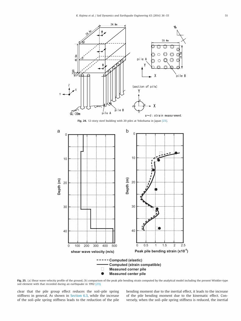
In order to investigate the accuracy and reliability of thepresent response spectrum method, a comparison has been madefor an actual building with piles [29]. The overview of thebuilding-pile model in Yokohama, Japan is shown in Fig. 24. This
K. Kojima et al. / Soil Dynamics and Earthquake Engineering 63 (2014) 36–5554
steel-frame building consists of 12 stories and is supported by 20cast-in-place reinforced concrete piles, 35 m long and 1.7 m indiameter. To compare the peak response of bending strains ofpiles, an overall interaction system as shown in Fig. 5(b) has beenused. This overall interaction model includes the present Winkler-type soil element and the difference is the shape functions for thefree-field ground and piles, i.e. a linear function for the free-fieldground and a cubic function for the piles. Fig. 25(a) shows theshear wave velocity profile of the ground. Fig. 25(b) illustrates thecomparison of the peak pile bending strain computed by theanalytical model including the present Winkler-type soil elementwith that recorded during an earthquake in 1992. A fairly goodagreement can be observed near the pile head and this demon-strates the validity of the present response spectrum method. Thisbending strain contains both the inertial effect and the kinematiceffect. It may also be said that the pile-group effect is rather smallin this case.
References
[1] Gazetas G, Dobry R. Horizontal response of piles in layered soils. J GeotechEng, ASCE 1984;110(1):20–40.
[2] Kavvadas M, Gazetas G. Kinematic seismic response and bending of free-headpiles in layered soil. Geotechnique 1993;43(2):207–22.
[3] Miyamoto Y, Fukuoka A, Adachi N, Sako Y. Pile response induced by inertialand kinematic interaction in liquefied soil deposit. J Struct Construct Eng, AIJ1996;482:53–62 (In Japanese).
[4] Mylonakis G, Nikolaou A, Gazetas G. Soil–pile–bridge seismic interaction:kinematic and inertial effects. Part I; soft soil. Earthq Eng Struct Dyn1997;26:337–59.
[5] Boulanger RW, Curras JC, Kuter BL, Wilson DW, Abghari A. Seismic soil–pile–structure interaction experiments and analyses. J Geotech Geoenviron EngASCE 1999;125(9):750–9.
[6] Murono Y, Nishimura A. Evaluation of seismic force of pile foundation inducedby inertial and kinematic interaction. In: Proceedings of the 12th WorldConference on Earthquake Engineering, Paper No.1496; 2000.
[7] Dobry R, Abdoun T, O'Rourke TD, Goh SH. Single piles in lateral spreads: fieldbending moment evaluation. J Geotech Geoenviron Eng ASCE 2003;129(10):879–89.
[8] Tokimatsu K, Suzuki H, Sato M. Effects of dynamic soil–structure interactionon pile stress. J Struct Construct Eng, AIJ 2005;587:125–32 (In Japanese).
[9] Tokimatsu K, Suzuki H, Sato M. Effects of inertial and kinematic interaction onseismic behavior of pile with embedded foundation. Soil Dyn Earthq Eng2005;25:753–62.
[10] Kishida A, Takewaki I. Response spectrum method for kinematic soil–pileinteraction analysis. Adv Struct Eng 2010;13(1):181–97.
[11] Ashford S, Boulanger R, Brandenberg S. Recommended design practice for pilefoundations in laterally spreading ground, PEER Report, No. PEER 2011/04;2011.
[12] Takewaki I, Nakamura T, Hirayama K. Seismic frame design via inverse modedesign of frame-ground systems. Soil Dyn Earthq Eng 1998;17(3):153–63.
[13] Lysmer J, Udaka T, Tsai C-F, Seed HB. FLUSH: a computer program forrapproximate3-D analysis of soil–structure interaction problems. EarthquakeEngineering Research Center Report No. EERC 75-30. Berkeley: University ofCalifornia; 1975.
[14] Der Kiureghian A. A response spectrum method for random vibrations.Earthquake Engineering Research Center, Report No. UCB/EERC 80-15. Berke-ley, California, USA: University of California; 1980.
[15] Wilson EL, Der Kiureghian A, Bayo EP. A replacement for the SRSS method inseismic analysis. Earthq Eng Struct Dyn 1981;9:187–94.
[16] Takewaki I, Murakami S, Fujita K, Yoshitomi S, Tsuji M. The 2011 off the Pacificcoast of Tohoku earthquake and response of high-rise buildings under long-period ground motions. Soil Dyn Earthq Eng 2011;31(11):1511–28.
[17] Takewaki I, Fujita K, Yoshitomi S. Uncertainties in long-period ground motionand its impact on building structural design: case study of the 2011 Tohoku(Japan) earthquake. Eng Struct 2013;49:119–34.
[18] Schnabel PB, Lysmer J, Seed HB. SHAKE: a computer program for earthquakeresponse analysis of horizontally layered sites. Berkeley: A computer programdistributed by NISEE/Computer Applications; 1972.
[19] Ching J-Y, Glaser SD. 1D time-domain solution for seismic ground motionprediction. J Geotech Geoenviron Eng, ASCE 2001;127(1):36–47.
[20] Yang JN, Sarkani S, Long FX. Response spectrum approach for seismic analysisof nonclassically damped structures. Eng Struct 1990;12:173–84.
[21] Nakamura T, Takewaki I, Asaoka Y. Sequential stiffness design for seismic driftranges of a shear building–pile–soil system. EarthqEng Struct Dyn 1996;25(12):405–20.
[22] Takewaki I. Inverse stiffness design of shear-flexural building models includ-ing soil–structure interaction. Eng Struct 1999;21(12):1045–54.
[23] Takewaki I. Frequency domain analysis of earthquake input energy tostructure–pile systems. Eng Struct 2005;27(4):549–63.
[24] Takewaki I. Response spectrum method for nonlinear surface ground analysis.Int J Adv Struct Eng 2004;7(6):503–14.
[25] Tajimi H. A contribution to theoretical prediction on dynamic stiffness surfacefoundations. In: Proceedings of the 7th World Conference on EarthquakeEngineering, Istanbul; 1980, p. 105–112.
[26] Tassoulas JL, Kausel E. Elements for the numerical analysis of wave motion inlayered strata. Int J Numer Methods Eng 1983;19(7):1005–32.
[27] Kausel E. The thin-layer method in seismology and earthquake engineering.In: Kausel E, Manolis GD, editors. Wave motion in earthquake engineering.Southampton, UK: WIT Press; 2000; 193–213.
[28] Newmark NM, Hall WJ. Earthquake spectra and design. Berkeley, CA: Earth-quake Engineering Research Institute; 1982.
[29] Nikolaou S, Mylonakis G, Gazetas G, Tazoh T. Kinematic pile bending duringearthquakes: analysis and field measurements. Geotechnique 2001;51(5):425–40.
[30] Takewaki I, Kishida A. Efficient analysis of pile-group effect on seismicstiffness and strength design of buildings. Soil Dyn Earthq Eng 2005;25(5):355–67.
[31] Makris N, Gazetas G. Dynamic pile–soil–pile interaction, part II: lateral andseismic response. Earthq Eng Struct Dyn 1992;21:145–62.
K. Kojima et al. / Soil Dynamics and Earthquake Engineering 63 (2014) 36–55 55
Guilherme
Rectângulo
Related Documents