Kinematic pile bending during earthquakes: analysis and field measurements S. NIKOLAOU , G. MYLONAKIS { , G. GAZETAS { and T. TAZOH } The passage of seismic waves through the soil surrounding a pile imposes lateral displacements and curvatures on the pile, thereby generating ‘kinematic’ bending moments even in the absence of a superstructure. These moments are concentrated in the vicinity of interfaces of alternating soft and stiff soil layers and, in the case of restrained-head piles, at the pile head. The scope of this paper is threefold: (a) to critically review some existing design methods for kinematic pile loading; (b) to develop new analytical results for piles in homogeneous and layered soils; (c) to present a case study in which theoretical predictions are tested against field mea- surements. To this end, an approximate beam-on-dynamic- Winkler-foundation (BDWF) model is implemented, specifi- cally developed for the seismic response of piles in layered soil. Both fixed- and free-head piles, and different boundary conditions at the pile toe, are considered. It is shown that the magnitude of kinematic moments depends mainly on the stiffness contrast between the soil layers, the pile–soil stiff- ness contrast, the excitation frequency, and the number of excitation cycles. A unique case history involving the instru- mented pile foundation of a multistorey building in Japan is presented. Time histories of bending and axial strains re- corded at six locations along two piles are successfully com- pared with results computed from simple formulae and methods presented in the paper. KEYWORDS: case history; dynamics; earthquakes; numerical modelling and analysis; piles; soil structure interaction. Le passage d’ondes sismiques dans le sol qui entoure une pile impose des de ´placements late ´raux et des courbures a ` la pile, engendrant de la sorte des couples de flexion ‘cine ´ma- tiques’ me ˆme en l’absence d’une superstructure. Ces couples se concentrent dans le voisinage des interfaces de couches alterne ´es de sol tendre et de sol rigide et, dans le cas de piles a ` te ˆte retenue, au sommet de la pile. Cet expose ´ a donc trois objectifs : (a) passer en revue et juger certaines des me ´thodes de conception existantes relatives au chargement de pile cine ´matique ; (b) de ´velopper de nouveaux re ´sultats analytiques pour des piles dans des sols homoge `nes et des sols constitue ´s de couches ; (c) pre ´senter une e ´tude de cas dans laquelle les pre ´dictions the ´oriques sont compare ´es aux mesures prises sur le terrain. Dans ce but, nous avons utilise ´ une maquette approximative de Winkler (BDWF), de ´velop- pe ´e spe ´cifiquement pour e ´tudier la re ´action sismique des piles dans des sols constitue ´s de couches. Nous e ´tudions les piles a ` te ˆte fixe et les piles a ` te ˆte libre ainsi que les diffe ´rentes conditions limites au pied de la pile. Nous mon- trons que la magnitude des couples cine ´matiques de ´pend principalement du contraste de rigidite ´ entre les couches de sol, du contraste de rigidite ´ entre la pile et le sol, de la fre ´quence d’excitation et le nombre de cycles d’excitation. Nous pre ´sentons une histoire de cas unique sur les fonda- tions de piles instrumente ´es d’un ba ˆtiment de plusieurs e ´tages au Japon. Les histoires de temps pour les de ´forma- tions fle ´chies et axiales enregistre ´es a ` six emplacements le long de deux piles montrent une bonne corre ´lation avec les re ´sultats calcule ´s d’apre `s les formules et les me ´thodes sim- ples pre ´sente ´es dans cet expose ´. INTRODUCTION Pile damage due to seismic shaking has been observed in numerous post-earthquake investigations around the world (Ross et al., 1969; Margason, 1975; CNEL-ENEL, 1976; Okamoto, 1983; Nishizawa et al., 1984; EEFIT, 1986). Mizuno (1987) reported 28 cases involving seismic failures of piles in Japan. More recently, pile damage was observed in the Loma Prieta earthquake (1989) and particularly in the Kobe earthquake (1995). Identified or suspected causes of failure in the above cases include: (a) large pile movements due to liquefaction and subsequent lateral soil spreading (b) excessive bending and shear forces transmitted to the piles from the superstructure (c) bending due to vibratory deformations induced by the passage of seismic waves through the soil. Support for the third scenario comes from the fact that damage has often been observed too deep to have been caused by loading coming from the pile top, in soils that could not possibly have suffered a severe loss of strength (e.g. liquefac- tion). Analytical and field evidence (Dobry & O’Rourke, 1983; Mizuno, 1987; Tazoh et al., 1987) have associated this type of damage with the presence of strong discontinuities in strength and, especially, stiffness in the soil profile. The most likely cause is the relatively large curvatures imposed on the piles by the surrounding soil, as it deforms while excited by the up- and down- (after reflection) propagating seismic waves. The reason is that soil shear strain is discontinuous across interfaces because of the different shear moduli between the layers, and thereby the associated soil curvature (the derivative of strain) is infinite. Accordingly, this type of distress is called kinematic, to distinguish it from the inertial distress (type (b)) due to head loading arising from the inertia forces in the superstructure. Tajimi (1969) and Penzien (1970) were among the first to study the problem, by using an analytical and numerical approach respectively. Following these early efforts, the problem was analysed by Margason (1975), Blaney et al. (1976), Kagawa & Kraft (1980), Flores-Berrones & Whit- man (1982), Kaynia & Kausel (1982), Dobry & O’Rourke (1983), Barghouthi (1984), Tazoh et al. (1987), Mineiro (1989), Mamoon & Banerjee (1990), Kavvadas & Gazetas (1993), Nikolaou et al. (1995), Kaynia & Mahzooni (1996), Guin & Banerjee (1998) Luo & Murono (2001) and others. Most of these studies focus on the dynamic response of the pile head; the associated curvatures and bending moments along the pile have received less attention. Reviews on the subject have been presented by Novak (1991), Pender (1993), and Gazetas & Mylonakis (1998). Despite the above research efforts, and some documented cases of kinematically induced damage to piles, this mode of response does not usually receive proper attention by engineers. Instead, seismically loaded piles are traditionally designed to withstand only the flexural stresses generated from the oscilla- tions of the superstructure. Nevertheless, the importance of 425 Nikolaou, S., Mylonakis, G., Gazetas, G. & Tazoh T. (2001). Ge ´otechnique 51, No. 5, 425–440 Manuscript received 26 July 2000; revised manuscript accepted 9 March 2001. Discussion on this paper closes 2 November 2001, for further details see the inside back cover. Mueser Rutledge Consulting Engineers, New York. { City University of New York. { National Technical University, Athens. } Shimizu Corporation, Tokyo.

Welcome message from author
This document is posted to help you gain knowledge. Please leave a comment to let me know what you think about it! Share it to your friends and learn new things together.
Transcript
Kinematic pile bending during earthquakes: analysis and ®eld measurements
S. NIKOLAOU�, G. MYLONAKIS{ , G. GAZETAS{ and T. TAZOH}
The passage of seismic waves through the soil surrounding apile imposes lateral displacements and curvatures on thepile, thereby generating `kinematic' bending moments evenin the absence of a superstructure. These moments areconcentrated in the vicinity of interfaces of alternating softand stiff soil layers and, in the case of restrained-head piles,at the pile head. The scope of this paper is threefold: (a) tocritically review some existing design methods for kinematicpile loading; (b) to develop new analytical results for piles inhomogeneous and layered soils; (c) to present a case study inwhich theoretical predictions are tested against ®eld mea-surements. To this end, an approximate beam-on-dynamic-Winkler-foundation (BDWF) model is implemented, speci®-cally developed for the seismic response of piles in layeredsoil. Both ®xed- and free-head piles, and different boundaryconditions at the pile toe, are considered. It is shown thatthe magnitude of kinematic moments depends mainly on thestiffness contrast between the soil layers, the pile±soil stiff-ness contrast, the excitation frequency, and the number ofexcitation cycles. A unique case history involving the instru-mented pile foundation of a multistorey building in Japan ispresented. Time histories of bending and axial strains re-corded at six locations along two piles are successfully com-pared with results computed from simple formulae andmethods presented in the paper.
KEYWORDS: case history; dynamics; earthquakes; numericalmodelling and analysis; piles; soil structure interaction.
Le passage d'ondes sismiques dans le sol qui entoure unepile impose des deÂplacements lateÂraux et des courbures aÁ lapile, engendrant de la sorte des couples de ¯exion `cineÂma-tiques' meÃme en l'absence d'une superstructure. Ces couplesse concentrent dans le voisinage des interfaces de couchesalterneÂes de sol tendre et de sol rigide et, dans le cas depiles aÁ teÃte retenue, au sommet de la pile. Cet expose a donctrois objectifs : (a) passer en revue et juger certaines desmeÂthodes de conception existantes relatives au chargementde pile cineÂmatique ; (b) deÂvelopper de nouveaux reÂsultatsanalytiques pour des piles dans des sols homogeÁnes et dessols constitueÂs de couches ; (c) preÂsenter une eÂtude de casdans laquelle les preÂdictions theÂoriques sont compareÂes auxmesures prises sur le terrain. Dans ce but, nous avons utiliseÂune maquette approximative de Winkler (BDWF), deÂvelop-peÂe speÂci®quement pour eÂtudier la reÂaction sismique despiles dans des sols constitueÂs de couches. Nous eÂtudions lespiles aÁ teÃte ®xe et les piles aÁ teÃte libre ainsi que lesdiffeÂrentes conditions limites au pied de la pile. Nous mon-trons que la magnitude des couples cineÂmatiques deÂpendprincipalement du contraste de rigidite entre les couches desol, du contraste de rigidite entre la pile et le sol, de lafreÂquence d'excitation et le nombre de cycles d'excitation.Nous preÂsentons une histoire de cas unique sur les fonda-tions de piles instrumenteÂes d'un baÃtiment de plusieurseÂtages au Japon. Les histoires de temps pour les deÂforma-tions ¯eÂchies et axiales enregistreÂes aÁ six emplacements lelong de deux piles montrent une bonne correÂlation avec lesreÂsultats calculeÂs d'apreÁs les formules et les meÂthodes sim-ples preÂsenteÂes dans cet exposeÂ.
INTRODUCTION
Pile damage due to seismic shaking has been observed innumerous post-earthquake investigations around the world (Rosset al., 1969; Margason, 1975; CNEL-ENEL, 1976; Okamoto,1983; Nishizawa et al., 1984; EEFIT, 1986). Mizuno (1987)reported 28 cases involving seismic failures of piles in Japan.More recently, pile damage was observed in the Loma Prietaearthquake (1989) and particularly in the Kobe earthquake(1995). Identi®ed or suspected causes of failure in the abovecases include:
(a) large pile movements due to liquefaction and subsequentlateral soil spreading
(b) excessive bending and shear forces transmitted to the pilesfrom the superstructure
(c) bending due to vibratory deformations induced by thepassage of seismic waves through the soil.
Support for the third scenario comes from the fact that damagehas often been observed too deep to have been caused byloading coming from the pile top, in soils that could notpossibly have suffered a severe loss of strength (e.g. liquefac-tion). Analytical and ®eld evidence (Dobry & O'Rourke, 1983;Mizuno, 1987; Tazoh et al., 1987) have associated this type of
damage with the presence of strong discontinuities in strengthand, especially, stiffness in the soil pro®le. The most likelycause is the relatively large curvatures imposed on the piles bythe surrounding soil, as it deforms while excited by the up- anddown- (after re¯ection) propagating seismic waves. The reasonis that soil shear strain is discontinuous across interfacesbecause of the different shear moduli between the layers, andthereby the associated soil curvature (the derivative of strain) isin®nite. Accordingly, this type of distress is called kinematic, todistinguish it from the inertial distress (type (b)) due to headloading arising from the inertia forces in the superstructure.
Tajimi (1969) and Penzien (1970) were among the ®rstto study the problem, by using an analytical and numericalapproach respectively. Following these early efforts, theproblem was analysed by Margason (1975), Blaney et al.(1976), Kagawa & Kraft (1980), Flores-Berrones & Whit-man (1982), Kaynia & Kausel (1982), Dobry & O'Rourke(1983), Barghouthi (1984), Tazoh et al. (1987), Mineiro(1989), Mamoon & Banerjee (1990), Kavvadas & Gazetas(1993), Nikolaou et al. (1995), Kaynia & Mahzooni (1996),Guin & Banerjee (1998) Luo & Murono (2001) and others.Most of these studies focus on the dynamic response of thepile head; the associated curvatures and bending momentsalong the pile have received less attention. Reviews on thesubject have been presented by Novak (1991), Pender(1993), and Gazetas & Mylonakis (1998).
Despite the above research efforts, and some documentedcases of kinematically induced damage to piles, this mode ofresponse does not usually receive proper attention by engineers.Instead, seismically loaded piles are traditionally designed towithstand only the ¯exural stresses generated from the oscilla-tions of the superstructure. Nevertheless, the importance of
425
Nikolaou, S., Mylonakis, G., Gazetas, G. & Tazoh T. (2001). GeÂotechnique 51, No. 5, 425±440
Manuscript received 26 July 2000; revised manuscript accepted 9 March2001.Discussion on this paper closes 2 November 2001, for further detailssee the inside back cover.� Mueser Rutledge Consulting Engineers, New York.{ City University of New York.{ National Technical University, Athens.} Shimizu Corporation, Tokyo.
kinematic loading has started to be recognised in recent seismicprovisions. For example, Part 5 of the recently publishedEuropean seismic code EC-8 (1996) states:
`Piles shall be designed for the following two loadingconditions:
(a) inertia forces from the superstructure . . .(b) soil deformations arising from the passage of seismic
waves which impose curvatures and thereby lateral strainon the piles along their whole length . . . Such kinematicloading may be particularly large at interfaces of soillayers with sharply different shear moduli. The designmust ensure that `no plastic hinge' develops at suchlocations . . .'
An analogous statement can be found in the Seismic guidelinesfor ports (TCLEE, 1998), which in Part 6 deals with kinematicloads. The increasing awareness of practising engineers of theimportance of kinematic loading can be noticed from reports inprofessional journals (e.g. European Foundations, Spring 1998;Pappin et al., 1998).
This paper is aimed at improving current understanding ofthe importance of kinematic loading on the seismic performanceof piles. This is done in three parts: ®rst, two existing designmethods are critically reviewed; second, new analytical resultsfor piles in homogeneous and layered soil deposits are devel-oped by implementing a pertinent bean-on-dynamic-Winklerfoundation (BDWF) model; third, a case study is presented inwhich theoretical predicitons are tested against ®eld measure-ments.
REVIEW OF AVAILABLE DESIGN METHODS
Margason (1975) and NEHRP (1997)In one of the earliest methods for kinematic pile bending,
Margason (1975) assumes that a long pile follows the motion ofthe surrounding soil. Based on this assumption, the kinematicbending moments are determined by considering the peak cur-vature developing in the free-®eld soil:
M � Ep Ip (1=R) (1)
where M � peak pile bending moment; (1=R) � peak `soil'curvature; (Ep Ip) � pile ¯exural stiffness. To compute (1=R),Margason proposes the following relation:
(1=R) � 2 ÄUff=Äz2 (2)
in which ÄUff is the relative lateral displacement between twopoints in the soil separated by a vertical distance Äz. Thisrelation is based on approximating the de¯ected shape of thepile by a circular arc: that is, assuming that the pile is subjectedto pure bending. Margason (1975) argues that peak soil curva-tures during severe earthquakes are not likely to exceed about0´02 mÿ1 (if liquefaction does not develop).
An analogous approach is proposed in the NEHRP (1997)seismic provisions: assuming that the pile follows the free-®eldsoil motion, and considering only vertically propagating Swaves, the curvature in the free-®eld soil is obtained from theone-dimensional wave equation (Newmark, 1968; NEHRP,1997):
(1=R) � aff=Vs2 (3)
where aff denotes the free-®eld soil acceleration and Vs thepropagation velocity of shear waves in the soil material.
The accuracy of the above equations will be examined below.In the interim, the following points are worthy of note. First, inequations (2) and (3) the interaction between pile and soil isneglected. Accordingly, several important parameters such asthe pile±soil relative stiffness, pile length to diameter ratio(`slenderness ratio') and radiation damping are not incorporated.Second, the methods are inapplicable to interfaces betweendifferent layers. As mentioned earlier, soil strains are discontin-uous across such interfaces, and thereby the corresponding soilcurvatures are theoretically in®nite. In contrast, curvatures in
elastic piles are ®nite. This gives rise to an interaction betweenthe pile and the soil at the vicinity of the interface that cannotbe captured by equations (2) or (3). Third, results from thesemethods may lead to erroneous design rules if carelessly inter-preted. For instance, the peak bending strain, åp, in a cross-section of the pile is
åp � (1=R) r (4)
where r is the distance from the neutral axis to the farthest®bre in the cross-section. Bending strain is useful in evaluatingthe seismic performance of a pile because
(a) it is dimensionless(b) it is directly measurable experimentally(c) it can be used to quantify damage(d ) ultimate (`failure') bending strains do not vary signi®cantly
among common structural materials. (Typically, strains ofthe order of one thousandth are enough to in¯ict damage inconventionally designed concrete or steel beams)
As mentioned earlier, Margason's method determines 1=R basedonly on the properties of the soil and the excitation (equations(2), (3)). Therefore, one would conclude from equation (4) thatthe peak bending strain increases proportionally with the pileradius r. This may lead to the conclusion (see Bertero et al.,1974; Margason, 1975) that small-diameter piles are superior tolarge-diameter piles for kinematic loading. As will be shownlater, this may or may not be true, depending on the circum-stances.
Dobry & O'Rourke (1983)A simple model for determining kinematic pile bending
moments at the interface of two soil layers has been proposedby Dobry & O'Rourke (1983). Their main assumptions are asfollows:
(a) The pile is long, and the two soil layers are suf®cientlythick for the response of the pile outside these layers (e.g. atthe pile head or at the pile toe) not to in¯uence the responseat the interface.
(b) The soil is subjected to a uniform shear stress, whichgenerates uniform strain within each layer.
Based on these assumptions, and modelling the pile as a beamon Winkler foundation, Dobry & O'Rourke derived an explicitsolution for the pile bending at the interface. Expressed in termsof bending strain, their solution can be cast as
åp � 2r ë1ã1 F (5)
where ã1 is the soil shear at the interface, and ë1 is the well-known Winkler parameter (Scott, 1981),
ë1 � k1
4Ep Ip
� �1=4
(6)
referring to the properties of the ®rst layer. k1 denotes themodulus of the Winkler springs in the ®rst (top) layer, and itwas taken by Dobry & O'Rourke as three times the shearmodulus of the material: that is, k1 � 3G1. F denotes thedimensionless function
F � cÿ3(cÿ 1)(c2 ÿ c� 1) (7a)
in which c expresses the ratio of the shear moduli of the twolayers:
c � (G2=G1)1=4 (7b)
The Dobry±O'Rourke (1983) model provides a practical toolfor determining kinematic interface moments. In contrast to thesimplistic Margason/NEHRP method, the model takes into ac-count the interaction between soil and pile and thus overcomesthe problem of singular soil curvature at the interface. Never-theless, the dynamic nature of the excitation and the effect ofthe ®nite thickness of the soil layers are not incorporated. In
426 NIKOLAOU, MYLONAKIS, GAZETAS AND TAZOH
addition, as will be shown later on, this solution by substantiallyoverpredict the actual pile bending in certain cases.
BEAM-ON-DYNAMIC-WINKLER-FOUNDATION MODEL
The response to vertical S-wave excitation of a single pile ina layered soil can be obtained numerically using suitable ®nite-element (FE) formulation with `wave transmitting' boundaries(e.g. the one described by Blaney et al., 1976), or a boundary-element-type code (e.g. the one described by Mamoon & Bane-rjee, 1990 and Banerjee 1995). However, such rigorous tools,even if available, have well-known limitations when used inseismic design. This is particularly true if seismic analysis usingactual or simulated ground motions is to be performed in thefrequency domain. Under these conditions, pile response mustbe computed for a large number of frequencies covering thefrequency content of the seismic signal. Therefore a simpli®edanalytical model would be quite useful provided it had beenshown to be in accord with the rigorous results for a wide rangeof pile types, soil pro®les, and excitation frequencies.
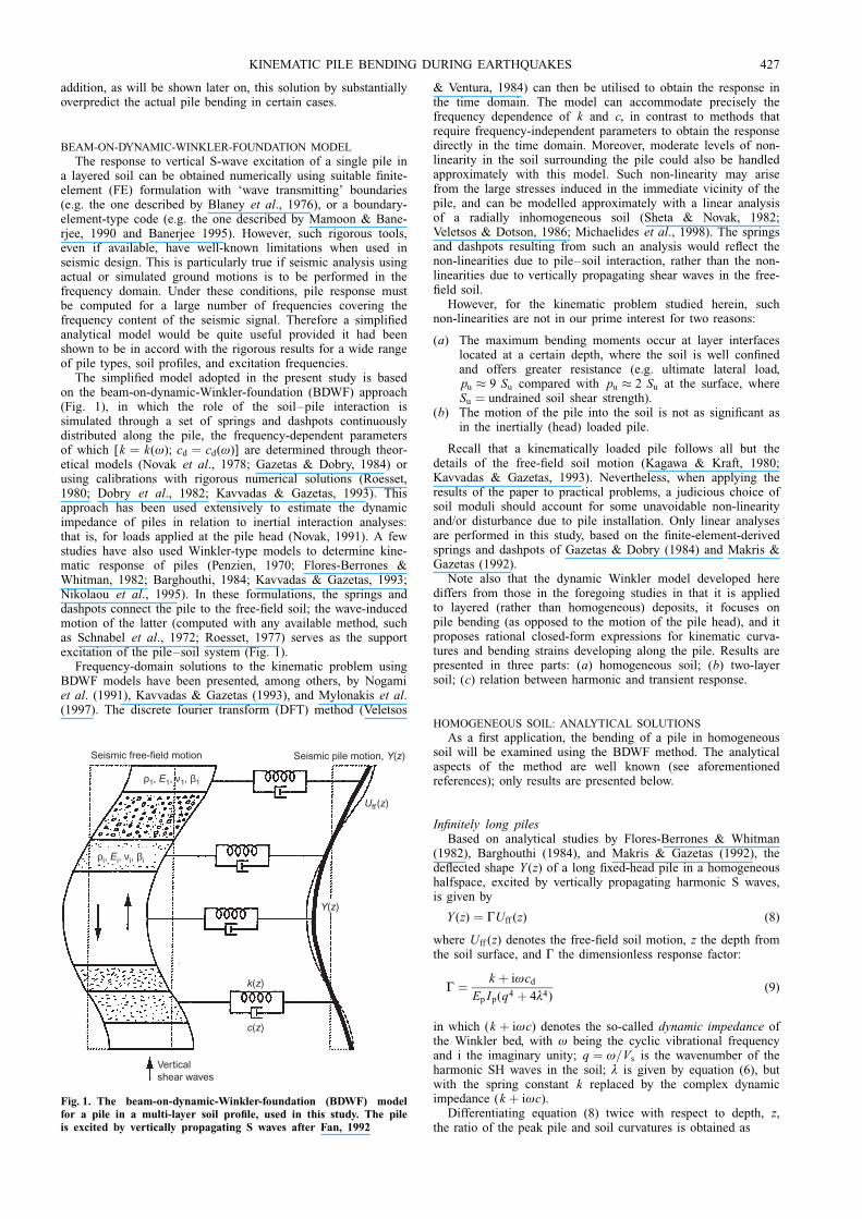
The simpli®ed model adopted in the present study is basedon the beam-on-dynamic-Winkler-foundation (BDWF) approach(Fig. 1), in which the role of the soil±pile interaction issimulated through a set of springs and dashpots continuouslydistributed along the pile, the frequency-dependent parametersof which [k � k(ù); cd � cd(ù)] are determined through theor-etical models (Novak et al., 1978; Gazetas & Dobry, 1984) orusing calibrations with rigorous numerical solutions (Roesset,1980; Dobry et al., 1982; Kavvadas & Gazetas, 1993). Thisapproach has been used extensively to estimate the dynamicimpedance of piles in relation to inertial interaction analyses:that is, for loads applied at the pile head (Novak, 1991). A fewstudies have also used Winkler-type models to determine kine-matic response of piles (Penzien, 1970; Flores-Berrones &Whitman, 1982; Barghouthi, 1984; Kavvadas & Gazetas, 1993;Nikolaou et al., 1995). In these formulations, the springs anddashpots connect the pile to the free-®eld soil; the wave-inducedmotion of the latter (computed with any available method, suchas Schnabel et al., 1972; Roesset, 1977) serves as the supportexcitation of the pile±soil system (Fig. 1).
Frequency-domain solutions to the kinematic problem usingBDWF models have been presented, among others, by Nogamiet al. (1991), Kavvadas & Gazetas (1993), and Mylonakis et al.(1997). The discrete fourier transform (DFT) method (Veletsos
& Ventura, 1984) can then be utilised to obtain the response inthe time domain. The model can accommodate precisely thefrequency dependence of k and c, in contrast to methods thatrequire frequency-independent parameters to obtain the responsedirectly in the time domain. Moreover, moderate levels of non-linearity in the soil surrounding the pile could also be handledapproximately with this model. Such non-linearity may arisefrom the large stresses induced in the immediate vicinity of thepile, and can be modelled approximately with a linear analysisof a radially inhomogeneous soil (Sheta & Novak, 1982;Veletsos & Dotson, 1986; Michaelides et al., 1998). The springsand dashpots resulting from such an analysis would re¯ect thenon-linearities due to pile±soil interaction, rather than the non-linearities due to vertically propagating shear waves in the free-®eld soil.
However, for the kinematic problem studied herein, suchnon-linearities are not in our prime interest for two reasons:
(a) The maximum bending moments occur at layer interfaceslocated at a certain depth, where the soil is well con®nedand offers greater resistance (e.g. ultimate lateral load,pu � 9 Su compared with pu � 2 Su at the surface, whereSu � undrained soil shear strength).
(b) The motion of the pile into the soil is not as signi®cant asin the inertially (head) loaded pile.
Recall that a kinematically loaded pile follows all but thedetails of the free-®eld soil motion (Kagawa & Kraft, 1980;Kavvadas & Gazetas, 1993). Nevertheless, when applying theresults of the paper to practical problems, a judicious choice ofsoil moduli should account for some unavoidable non-linearityand/or disturbance due to pile installation. Only linear analysesare performed in this study, based on the ®nite-element-derivedsprings and dashpots of Gazetas & Dobry (1984) and Makris &Gazetas (1992).
Note also that the dynamic Winkler model developed herediffers from those in the foregoing studies in that it is appliedto layered (rather than homogeneous) deposits, it focuses onpile bending (as opposed to the motion of the pile head), and itproposes rational closed-form expressions for kinematic curva-tures and bending strains developing along the pile. Results arepresented in three parts: (a) homogeneous soil; (b) two-layersoil; (c) relation between harmonic and transient response.
HOMOGENEOUS SOIL: ANALYTICAL SOLUTIONS
As a ®rst application, the bending of a pile in homogeneoussoil will be examined using the BDWF method. The analyticalaspects of the method are well known (see aforementionedreferences); only results are presented below.
In®nitely long pilesBased on analytical studies by Flores-Berrones & Whitman
(1982), Barghouthi (1984), and Makris & Gazetas (1992), thede¯ected shape Y (z) of a long ®xed-head pile in a homogeneoushalfspace, excited by vertically propagating harmonic S waves,is given by
Y (z) � ÃUff (z) (8)
where Uff (z) denotes the free-®eld soil motion, z the depth fromthe soil surface, and à the dimensionless response factor:
à � k � iùcd
Ep Ip(q4 � 4ë4)(9)
in which (k � iùc) denotes the so-called dynamic impedance ofthe Winkler bed, with ù being the cyclic vibrational frequencyand i the imaginary unity; q � ù=Vs is the wavenumber of theharmonic SH waves in the soil; ë is given by equation (6), butwith the spring constant k replaced by the complex dynamicimpedance (k � iùc).
Differentiating equation (8) twice with respect to depth, z,the ratio of the peak pile and soil curvatures is obtained as
Verticalshear waves
Seismic pile motion, Y(z)
ρ1, E1, ν1, β1
ρi, Ei, νi, βi
c(z)
k(z)
Y(z)
Uff (z)
Seismic free-field motion
Fig. 1. The beam-on-dynamic-Winkler-foundation (BDWF) modelfor a pile in a multi-layer soil pro®le, used in this study. The pileis excited by vertically propagating S waves after Fan, 1992
KINEMATIC PILE BENDING DURING EARTHQUAKES 427
(1=R)p
(1=R)s
� Ã (10)
For a free-head pile, the corresponding solution gives(Mylonakis, 1999)
(1=R)p
(1=R)s
� Ãmax[eÿëz(cos ëz� sin ëz)ÿ cos qz] (11)
The above expressions clearly indicate that pile curvature is notequal to soil curvature (as assumed by Margason (1975) andNEHRP (1997)); its value depends on the characteristics of thesoil and the pile, the excitation frequency, and the depth fromthe surface.
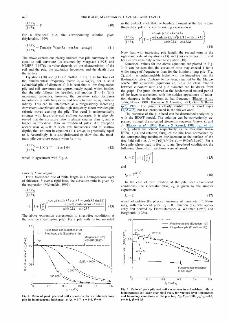
Equations (10) and (11) are plotted in Fig. 2 as functions ofthe dimensionless frequency factor a0 � ùd=Vs, for a solidcylindrical pile of diameter d. It is seen that at low frequenciespile and soil curvatures are approximately equal, which impliesthat the pile follows the free-®eld soil motion (Ã � 1). Withincreasing frequency, however, the curvature ratio decreasesmonotonically with frequency, and tends to zero as a0 tends toin®nity. This can be interpreted as a progressively increasingdestructive interference of the high-frequency (short-wavelength)seismic waves exciting the pile. The trend is understandablystronger with large pile±soil stiffness contrasts. It is also ob-served that the curvature ratio is always smaller than 1, and ishigher in free-head than in ®xed-head piles. An exceptionoccurs near a0 � 0: at such low frequencies and at shallowdepths, the last term in equation (11), cos qz, is practically equalto 1. Accordingly, it is straightforward to show that the maxi-mum pile curvature occurs when ëz � ð:
(1=R)p
(1=R)s
� 1 3 (eÿð � 1) ' 1:04 (12)
which in agreement with Fig. 2.
Piles of ®nite lengthFor a ®xed-head pile of ®nite length in a homogeneous layer
of thickness h over a rigid base, the curvature ratio is given bythe expression (Mylonakis, 1999)
(1=R)p
(1=R)s
� Ã 1� q
ë
� �2
cos qh (sinh ëh cos ëhÿ cosh ëh sin ëh)�(q=ë) cosh ëh cos ëh sin ëh
sinh 2ëh� sin 2ëh
24 35(13)
The above expression corresponds to stress-free conditions atthe pile toe (¯oating-toe pile). For a pile with its toe socketed
in the bedrock such that the bending moment at the toe is zero(hinged-toe pile), the corresponding expression is
(1=R)p
(1=R)s
� Ã 1ÿ 2
cos qh [cosh ëh cos ëh
�2 sinh ëh (ë=q)2[(1=Ã)ÿ 1]sin ëh]
cosh 2ëh� cos 2ëh
8<:9=;
(14)
Note that, with increasing pile length, the second term in theright-hand side of equations (13) and (14) converges to 1, andboth expressions duly reduce to equation (10).
Numerical values for the above equations are plotted in Fig.3. It can be seen that the curvature ratio may exceed 1 for awider range of frequencies than for the in®nitely long pile (Fig.2), and it is understandably higher with the hinged-toe than the¯oating-toe piles. Contrary to the trends incited by the Marga-son/NEHRP equations (equations (2), (3)), no clear relationbetween curvature ratio and pile diameter can be drawn fromthe graph. The jump observed at the fundamental natural periodof the layer is associated with the sudden appearance of radia-tion damping in the medium at that frequency (Blaney et al.,1976; Novak, 1991; Kavvadas & Gazetas, 1993; Guin & Bane-rjee, 1998). The jump is clearly visible in the short layer(h=d � 5), but less pronounced in the thicker ones.
The response of the pile head can be determined analyticallywith the BDWF model. The solution can be conveniently ex-pressed through the so-called kinematic response factors Iu andI f (Blaney et al., 1976; Kaynia & Kausel, 1982; Fan et al.,1991), which are de®ned, respectively, as the maximum trans-lation, Y (0), and rotation, È(0), of the pile head normalised bythe corresponding maximum displacement at the surface of thefree-®eld soil (i.e. Iu � Y (0)=Uff (0); Iö � È(0)d=Uff (0)). For along pile whose head is free to rotate (free-head conditions), thefollowing closed-form solutions were obtained:
Iu � Ã 1� 12
q
ë
� �2" #
(15)
and
Iö � Ãq2d
ë(16)
In the case of zero rotation at the pile head (®xed-headconditions), the kinematic ratio, Iu, is given by the simplerexpression
Iu � Ã (17)
which elucidates the physical meaning of parameter Ã. Natu-rally, with ®xed-head piles, Iö � 0. Equation (17) was appar-ently ®rst derived by Flores-Berrones & Whitman (1982) andBarghouthi (1984).
1·5
1·0
0·5
00
Fixed-head pile (Equation (10))Free-head pile (Equation (11))
0·1 0·2 0·3 0·4 0·5
Cur
vatu
re r
atio
, (1/
R) p
/(1/
R) s
a0 = ωd/Vs
Ep/Es = 1000
10 000
100 000
Margason (1975)NEHRP (1997)1·04
Fig. 2. Ratio of peak pile and soil curvatures for an in®nitely longpile in homogeneous halfspace: rrs=rrp 0:7, í 0:4, â 0
1·5
1·0
0·5
00
Floating-toe pile (Equation (13))Hinged-toe pile (Equation (14))
0·1 0·2 0·3 0·4 0·5
Cur
vatu
re r
atio
, (1/
R) p
/(1/
R) s
a0 = ωd/Vs
h/d = 20h/d = 10
h/d = 5
Fundamental frequencyof soil layer
Fig. 3. Ratio of peak pile and soil curvatures in a ®xed-head pile inhomogeneous soil layer over rigid rock, for various layer thicknessesand boundary conditions at the pile toe; Ep=Es 1000, rrs=rrp 0:7,í 0:4, â 0:05
428 NIKOLAOU, MYLONAKIS, GAZETAS AND TAZOH
LAYERED PROFILES: PARAMETRIC ANALYSIS
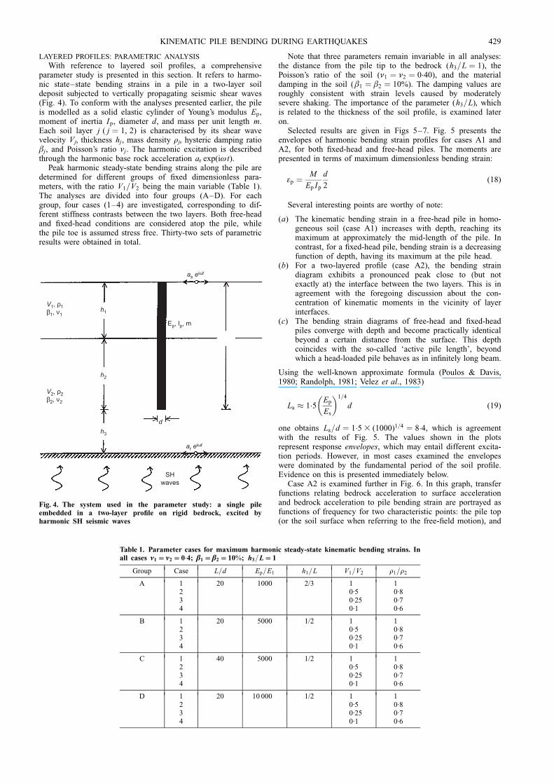
With reference to layered soil pro®les, a comprehensiveparameter study is presented in this section. It refers to harmo-nic state±state bending strains in a pile in a two-layer soildeposit subjected to vertically propagating seismic shear waves(Fig. 4). To conform with the analyses presented earlier, the pileis modelled as a solid elastic cylinder of Young's modulus Ep,moment of inertia Ip, diameter d, and mass per unit length m.Each soil layer j ( j � 1, 2) is characterised by its shear wavevelocity Vj, thickness hj, mass density rj, hysteric damping ratioâj, and Poisson's ratio íj. The harmonic excitation is describedthrough the harmonic base rock acceleration ar exp(iùt).
Peak harmonic steady-state bending strains along the pile aredetermined for different groups of ®xed dimensionless para-meters, with the ratio V1=V2 being the main variable (Table 1).The analyses are divided into four groups (A±D). For eachgroup, four cases (1±4) are investigated, corresponding to dif-ferent stiffness contrasts between the two layers. Both free-headand ®xed-head conditions are considered atop the pile, whilethe pile toe is assumed stress free. Thirty-two sets of parametricresults were obtained in total.
Note that three parameters remain invariable in all analyses:the distance from the pile tip to the bedrock (h3=L � 1), thePoisson's ratio of the soil (í1 � í2 � 0:40), and the materialdamping in the soil (â1 � â2 � 10%). The damping values areroughly consistent with strain levels caused by moderatelysevere shaking. The importance of the parameter (h3=L), whichis related to the thickness of the soil pro®le, is examined lateron.
Selected results are given in Figs 5±7. Fig. 5 presents theenvelopes of harmonic bending strain pro®les for cases A1 andA2, for both ®xed-head and free-head piles. The moments arepresented in terms of maximum dimensionless bending strain:
åp � M
Ep Ip
d
2(18)
Several interesting points are worthy of note:
(a) The kinematic bending strain in a free-head pile in homo-geneous soil (case A1) increases with depth, reaching itsmaximum at approximately the mid-length of the pile. Incontrast, for a ®xed-head pile, bending strain is a decreasingfunction of depth, having its maximum at the pile head.
(b) For a two-layered pro®le (case A2), the bending straindiagram exhibits a pronounced peak close to (but notexactly at) the interface between the two layers. This is inagreement with the foregoing discussion about the con-centration of kinematic moments in the vicinity of layerinterfaces.
(c) The bending strain diagrams of free-head and ®xed-headpiles converge with depth and become practically identicalbeyond a certain distance from the surface. This depthcoincides with the so-called `active pile length', beyondwhich a head-loaded pile behaves as in in®nitely long beam.
Using the well-known approximate formula (Poulos & Davis,1980; Randolph, 1981; Velez et al., 1983)
La � 1:5Ep
Es
� �1=4
d (19)
one obtains La=d � 1:5 3 (1000)1=4 � 8:4, which is agreementwith the results of Fig. 5. The values shown in the plotsrepresent response envelopes, which may entail different excita-tion periods. However, in most cases examined the envelopeswere dominated by the fundamental period of the soil pro®le.Evidence on this is presented immediately below.
Case A2 is examined further in Fig. 6. In this graph, transferfunctions relating bedrock acceleration to surface accelerationand bedrock acceleration to pile bending strain are portrayed asfunctions of frequency for two characteristic points: the pile top(or the soil surface when referring to the free-®eld motion), and
Table 1. Parameter cases for maximum harmonic steady-state kinematic bending strains. Inall cases í1 í2 0:4; â1 â2 10%; h3=L 1
Group Case L=d Ep=E1 h1=L V1=V2 r1=r2
A 1 20 1000 2/3 1 12 0´5 0´83 0´25 0´74 0´1 0´6
B 1 20 5000 1/2 1 12 0´5 0´83 0´25 0´74 0´1 0´6
C 1 40 5000 1/2 1 12 0´5 0´83 0´25 0´74 0´1 0´6
D 1 20 10 000 1/2 1 12 0´5 0´83 0´25 0´74 0´1 0´6
as eiωt
ar eiωt
h3
h2
h1
Ep, lp, m
d
V1, ρ1β1, ν1
V2, ρ2β2, ν2
SHwaves
Fig. 4. The system used in the parameter study: a single pileembedded in a two-layer pro®le on rigid bedrock, excited byharmonic SH seismic waves
KINEMATIC PILE BENDING DURING EARTHQUAKES 429
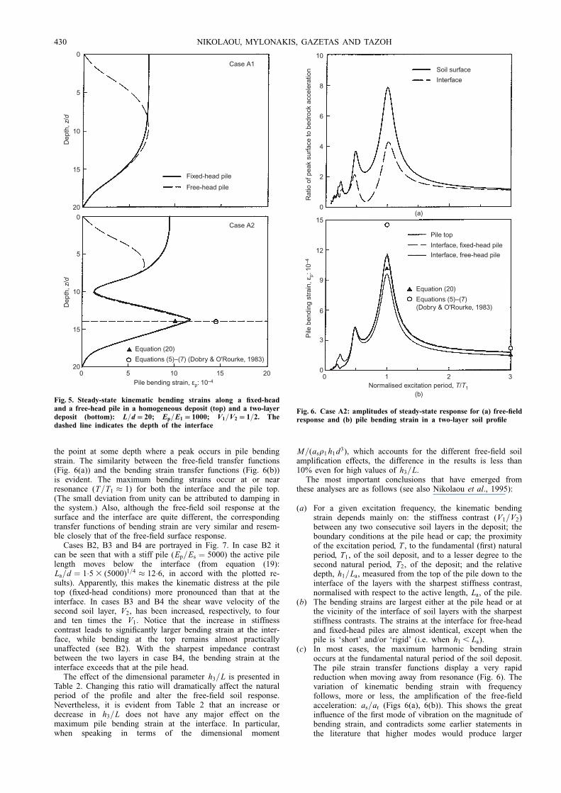
the point at some depth where a peak occurs in pile bendingstrain. The similarity between the free-®eld transfer functions(Fig. 6(a)) and the bending strain transfer functions (Fig. 6(b))is evident. The maximum bending strains occur at or nearresonance (T=T1 � 1) for both the interface and the pile top.(The small deviation from unity can be attributed to damping inthe system.) Also, although the free-®eld soil response at thesurface and the interface are quite different, the correspondingtransfer functions of bending strain are very similar and resem-ble closely that of the free-®eld surface response.
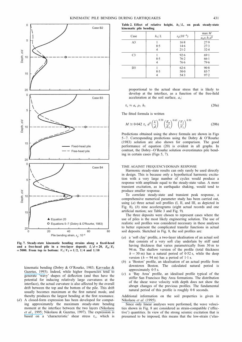
Cases B2, B3 and B4 are portrayed in Fig. 7. In case B2 itcan be seen that with a stiff pile (Ep=Es � 5000) the active pilelength moves below the interface (from equation (19):La=d � 1:5 3 (5000)1=4 � 12:6, in accord with the plotted re-sults). Apparently, this makes the kinematic distress at the piletop (®xed-head conditions) more pronounced than that at theinterface. In cases B3 and B4 the shear wave velocity of thesecond soil layer, V2, has been increased, respectively, to fourand ten times the V1. Notice that the increase in stiffnesscontrast leads to signi®cantly larger bending strain at the inter-face, while bending at the top remains almost practicallyunaffected (see B2). With the sharpest impedance contrastbetween the two layers in case B4, the bending strain at theinterface exceeds that at the pile head.
The effect of the dimensional parameter h3=L is presented inTable 2. Changing this ratio will dramatically affect the naturalperiod of the pro®le and alter the free-®eld soil response.Nevertheless, it is evident from Table 2 that an increase ordecrease in h3=L does not have any major effect on themaximum pile bending strain at the interface. In particular,when speaking in terms of the dimensional moment
M=(asr1 h1d3), which accounts for the different free-®eld soilampli®cation effects, the difference in the results is less than10% even for high values of h3=L.
The most important conclusions that have emerged fromthese analyses are as follows (see also Nikolaou et al., 1995):
(a) For a given excitation frequency, the kinematic bendingstrain depends mainly on: the stiffness contrast (V1=V2)between any two consecutive soil layers in the deposit; theboundary conditions at the pile head or cap; the proximityof the excitation period, T , to the fundamental (®rst) naturalperiod, T1, of the soil deposit, and to a lesser degree to thesecond natural period, T2, of the deposit; and the relativedepth, h1=La, measured from the top of the pile down to theinterface of the layers with the sharpest stiffness contrast,normalised with respect to the active length, La, of the pile.
(b) The bending strains are largest either at the pile head or atthe vicinity of the interface of soil layers with the sharpeststiffness contrasts. The strains at the interface for free-headand ®xed-head piles are almost identical, except when thepile is `short' and/or `rigid' (i.e. when h1 , La).
(c) In most cases, the maximum harmonic bending strainoccurs at the fundamental natural period of the soil deposit.The pile strain transfer functions display a very rapidreduction when moving away from resonance (Fig. 6). Thevariation of kinematic bending strain with frequencyfollows, more or less, the ampli®cation of the free-®eldacceleration: as=ar (Figs 6(a), 6(b)). This shows the greatin¯uence of the ®rst mode of vibration on the magnitude ofbending strain, and contradicts some earlier statements inthe literature that higher modes would produce larger
0
5
10
15
20
Dep
th, z
/d
0
5
10
15
20
Dep
th, z
/d
0 5 10 15 20Pile bending strain, εp: 10–4
Equation (20)
Equations (5)–(7) (Dobry & O'Rourke, 1983)
Case A2
Case A1
Fixed-head pile
Free-head pile
Fig. 5. Steady-state kinematic bending strains along a ®xed-headand a free-head pile in a homogeneous deposit (top) and a two-layerdeposit (bottom): L=d 20; Ep=E1 1000; V1=V2 1=2. Thedashed line indicates the depth of the interface
0
0
2
4
6
8
10
3
6
9
12
15
0 1 2 3
Pile
ben
ding
str
ain,
εp:
10–
4R
atio
of p
eak
surfa
ce to
bed
rock
acc
eler
atio
n
Equation (20)
Equations (5)–(7)(Dobry & O'Rourke, 1983)
Soil surface
Interface
Interface, fixed-head pile
Pile top
Interface, free-head pile
Normalised excitation period, T/T1(b)
(a)
Fig. 6. Case A2: amplitudes of steady-state response for (a) free-®eldresponse and (b) pile bending strain in a two-layer soil pro®le
430 NIKOLAOU, MYLONAKIS, GAZETAS AND TAZOH
kinematic bending (Dobry & O'Rourke, 1983; Kavvadas &Gazetas, 1993). Indeed, while higher frequencies tend togenerate `wavy' shapes of de¯ection (and thus have thepotential for inducing relatively large curvatures at theinterface), the actual curvature is also affected by the overalldrift between the top and the bottom of the pile. This driftusually becomes maximum at the ®rst natural mode, andthereby produces the largest bending at the ®rst resonance.
(d ) A closed-form expression has been developed for comput-ing approximately the maximum steady-state bendingmoment at the interface between the two layers (Nikolaouet al., 1995; Nikolaou & Gazetas, 1997). The expression isbased on a `characteristic' shear stress ôc, which is
proportional to the actual shear stress that is likely todevelop at the interface, as a function of the free-®eldacceleration at the soil surface, as:
ôc � as r1 h1 (20a)
The ®tted formula is written
M � 0:042 ôc d3 L
d
� �0:30Ep
E1
� �0:65V2
V1
� �0:50
(20b)
Predictions obtained using the above formula are shown in Figs5±7. Corresponding predictions using the Dobry & O'Rourke(1983) solution are also shown for comparison. The goodperformance of equation (20) is evident in all graphs. Incontrast, the Dobry±O'Rourke solution overestimates pile bend-ing in certain cases (Figs 5, 7).
TIME AGAINST FREQUENCY-DOMAIN RESPONSE
Harmonic steady-state results can only rarely be used directlyin design. This is because only a hypothetical harmonic excita-tion with a very large number of cycles would produce aresponse with amplitude equal to the steady-state value. A moretransient excitation, as in earthquake shaking, would tend toproduce smaller response.
To correlate steady-state and transient peak response, acomprehensive numerical parameter study has been carried out,using (a) three actual soil pro®les (I, II, and III, as depicted inFig. 8), (b) nine accelerograms (eight actual records and onearti®cial motion; see Table 3 and Fig. 9).
The three deposits were chosen to represent cases where theuse of piles is the most likely engineering solution. The use ofrealistic soil pro®les was considered necessary in these analysesto better represent the complicated transfer functions in actualsoil deposits. Sketched in Fig. 8, the soil pro®les are:
(a) a `soft clay' pro®le, a two-layer idealisation of an actual soilthat consists of a very soft clay underlain by stiff sandhaving thickness that varies parametrically from 30 m to94 m. The shallow version of the pro®le (total thicknessh � 30 m) has a natural period of 0´52 s, while the deepversion (h � 94 m) has a period of 1´1 s.
(b) a `Boston' pro®le, an idealisation of an actual pro®le fromdowntown Boston. The calculated natural period isapproximately 0´5 s.
(c) a `Bay Area' pro®le, an idealised pro®le typical of thestiffer San Francisco Bay Area formations. The distributionof the shear wave velocity with depth does not show theabrupt changes of the previous pro®les. The fundamentalnatural period of this pro®le is roughly 0´8 seconds.
Additional information on the soil properties is given inNikolaou et al. (1995).
Since only linear analyses were performed, the wave veloci-ties shown in Fig. 8 are considered as strain-compatible (`effec-tive') quantities. In view of the strong seismic excitation that ispresumed to be imposed, this means that the low-strain (`elas-
0
5
10
15
20
Dep
th, z
/d0
5
10
15
20
Dep
th, z
/d
0
5
10
15
20
Dep
th, z
/d
0 80604020Pile bending strain, εp: 10–4
Equation 20
Equations 5–7 (Dobry & O'Rourke, 1983)
Case B4
Case B3
Case B2
Fixed-head pile
Free-head pile
Fig. 7. Steady-state kinematic bending strains along a ®xed-headand a free-head pile in a two-layer deposit; L=d 20, Ep=E1
5000. From top to bottom: V1=V2 1=2, 1=4 and 1=10
Table 2. Effect of relative height, h3=L, on peak steady-statekinematic pile bending
Case h3=L åp(10ÿ4)max M
asr1 h1d3
A3 1 16´8 27´90´5 14´6 27´34 21´2 32´4
C3 1 92´6 69´10´5 76´2 66´14 76´6 79´6
D3 1 62´6 90´80´5 50´0 85´74 54´3 97´2
KINEMATIC PILE BENDING DURING EARTHQUAKES 431
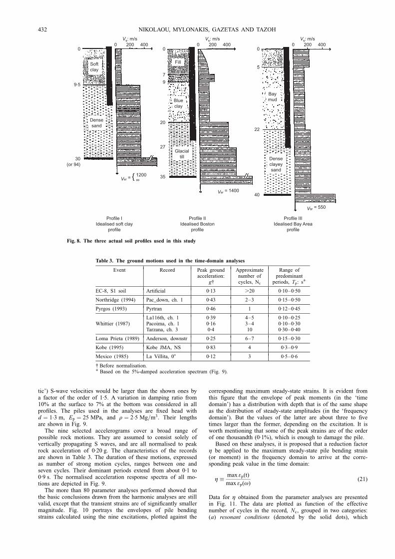
tic') S-wave velocities would be larger than the shown ones bya factor of the order of 1´5. A variation in damping ratio from10% at the surface to 7% at the bottom was considered in allpro®les. The piles used in the analyses are ®xed head withd � 1:3 m, Ep � 25 MPa, and r � 2:5 Mg=m3. Their lengthsare shown in Fig. 9.
The nine selected accelerograms cover a broad range ofpossible rock motions. They are assumed to consist solely ofvertically propagating S waves, and are all normalised to peakrock acceleration of 0´20 g. The characteristics of the recordsare shown in Table 3. The duration of these motions, expressedas number of strong motion cycles, ranges between one andseven cycles. Their dominant periods extend from about 0´1 to0´9 s. The normalised acceleration response spectra of all mo-tions are depicted in Fig. 9.
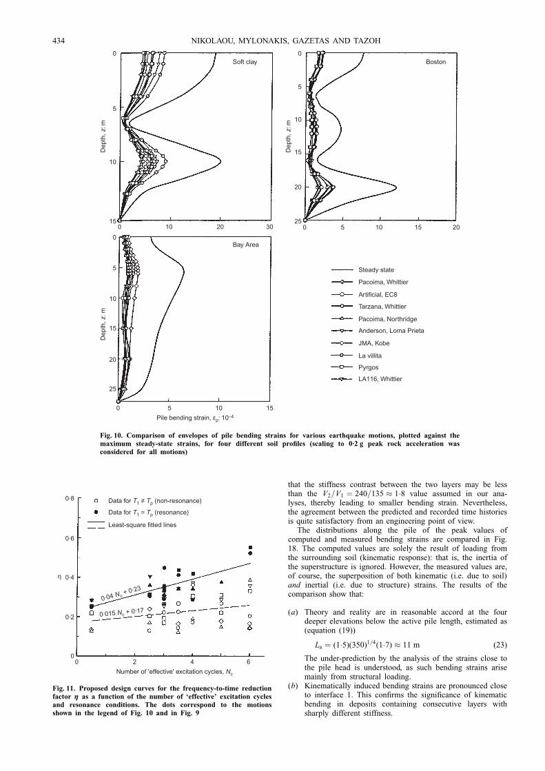
The more than 80 parameter analyses performed showed thatthe basic conclusions drawn from the harmonic analyses are stillvalid, except that the transient strains are of signi®cantly smallermagnitude. Fig. 10 portrays the envelopes of pile bendingstrains calculated using the nine excitations, plotted against the
corresponding maximum steady-state strains. It is evident fromthis ®gure that the envelope of peak moments (in the `timedomain') has a distribution with depth that is of the same shapeas the distribution of steady-state amplitudes (in the `frequencydomain'). But the values of the latter are about three to ®vetimes larger than the former, depending on the excitation. It isworth mentioning that some of the peak strains are of the orderof one thousandth (0´1%), which is enough to damage the pile.
Based on these analyses, it is proposed that a reduction factorç be applied to the maximum steady-state pile bending strain(or moment) in the frequency domain to arrive at the corre-sponding peak value in the time domain:
ç � max åp(t)
max åp(ù)(21)
Data for ç obtained from the parameter analyses are presentedin Fig. 11. The data are plotted as function of the effectivenumber of cycles in the record, Nc, grouped in two categories:(a) resonant conditions (denoted by the solid dots), which
Softclay
Densesand
Fill
Blueclay
Glacialtill
Baymud
Denseclayeysand
0 200 400Vs: m/s
0 200 400Vs: m/s
0 200 400Vs: m/s
00
7
9
20
27
35
0
9·5
30(or 94)
5
22
40
Vsr = {
Vsr = 1400
Vsr = 550
1200∞
Profile IIIIdealised Bay Area
profile
Profile IIIdealised Boston
profile
Profile IIdealised soft clay
profile
Fig. 8. The three actual soil pro®les used in this study
Table 3. The ground motions used in the time-domain analyses
Event Record Peak groundacceleration:
g{
Approximatenumber ofcycles, Nc
Range ofpredominant
periods, Tp: s�EC-8, S1 soil Arti®cial 0´13 .20 0´10±0´50
Northridge (1994) Pac_down, ch. 1 0´43 2±3 0´15±0´50
Pyrgos (1993) Pyrtran 0´46 1 0´12±0´45
La116th, ch. 1 0´39 4±5 0´10±0´25Whittier (1987) Pacoima, ch. 1 0´16 3±4 0´10±0´30
Tarzana, ch. 3 0´4 10 0´30±0´40
Loma Prieta (1989) Anderson, downstr 0´25 6±7 0´15±0´30
Kobe (1995) Kobe JMA, NS 0´83 4 0´3±0´9
Mexico (1985) La Villita, 08 0´12 3 0´5±0´6
{ Before normalisation.� Based on the 5%-damped acceleration spectrum (Fig. 9).
432 NIKOLAOU, MYLONAKIS, GAZETAS AND TAZOH
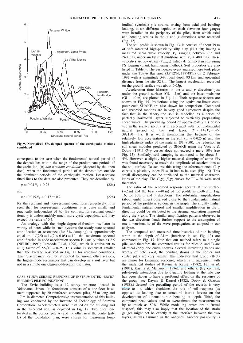
correspond to the case when the fundamental natural period ofthe deposit lies within the range of the predominant periods ofthe excitation; (b) non-resonant conditions (denoted by the opendots), when the fundamental period of the deposit lies outsidethe dominant periods of the earthquake motion. Least-square®tted lines to the data are also presented. They are described by
ç ' 0:04Nc � 0:23 (22a)
and
ç ' 0:015Nc � 0:17 ' 0:2 (22b)
for the resonant and non-resonant conditions respectively. It isseen that for non-resonant conditions ç is quite small, andpractically independent of Nc. By contrast, for resonant condi-tions, ç is understandably much more cycle-dependent, and mayexceed the value of 0´5.
An analogy with the single-degree-of-freedom oscillator isworthy of note: while in such systems the steady-state spectralampli®cation at resonance (for 5% damping) is approximatelyequal to 1=(2â) � 1=(2 3 0:05) � 10, the maximum spectralampli®cation in code acceleration spectra is usually taken as 2´5(NEHRP, 1997; Eurocode EC-8, 1996), which is equivalent toan ç factor of 2:5=10 � 0:25. This value is somewhat smallerthan the average observed in Fig. 11 for resonant conditions.This `discrepancy' can be attributed to, among other reasons,the higher-mode resonances that can develop in a soil layer butnot in a simple one-degree-of-freedom oscillator.
CASE STUDY: SEISMIC RESPONSE OF INSTRUMENTED `ERVIC'
BUILDING PILE FOUNDATION'
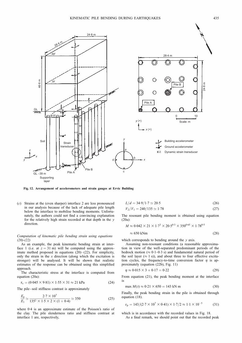
The Ervic building is a 12 storey structure located inYokohama, Japan. Its foundation consists of a one-¯oor base-ment supported by 20 reinforced concrete piles, 35 m long and1´7 m in diameter. Comprehensive instrumentation of this build-ing was conducted by the Institute of Technology of ShimizuCorporation. Accelerometers were installed on the building andin the free-®eld soil, as depicted in Fig. 12. Two piles, onelocated at the corner (pile A) and the other near the centre (pileB) of the foundation plan, were chosen for measuring long-
itudinal (vertical) pile strains, arising from axial and bendingloading, at six different depths. At each elevation four gaugeswere installed in the periphery of the piles, from which axialand bending strains in the x and y directions were recorded(Fig. 12).
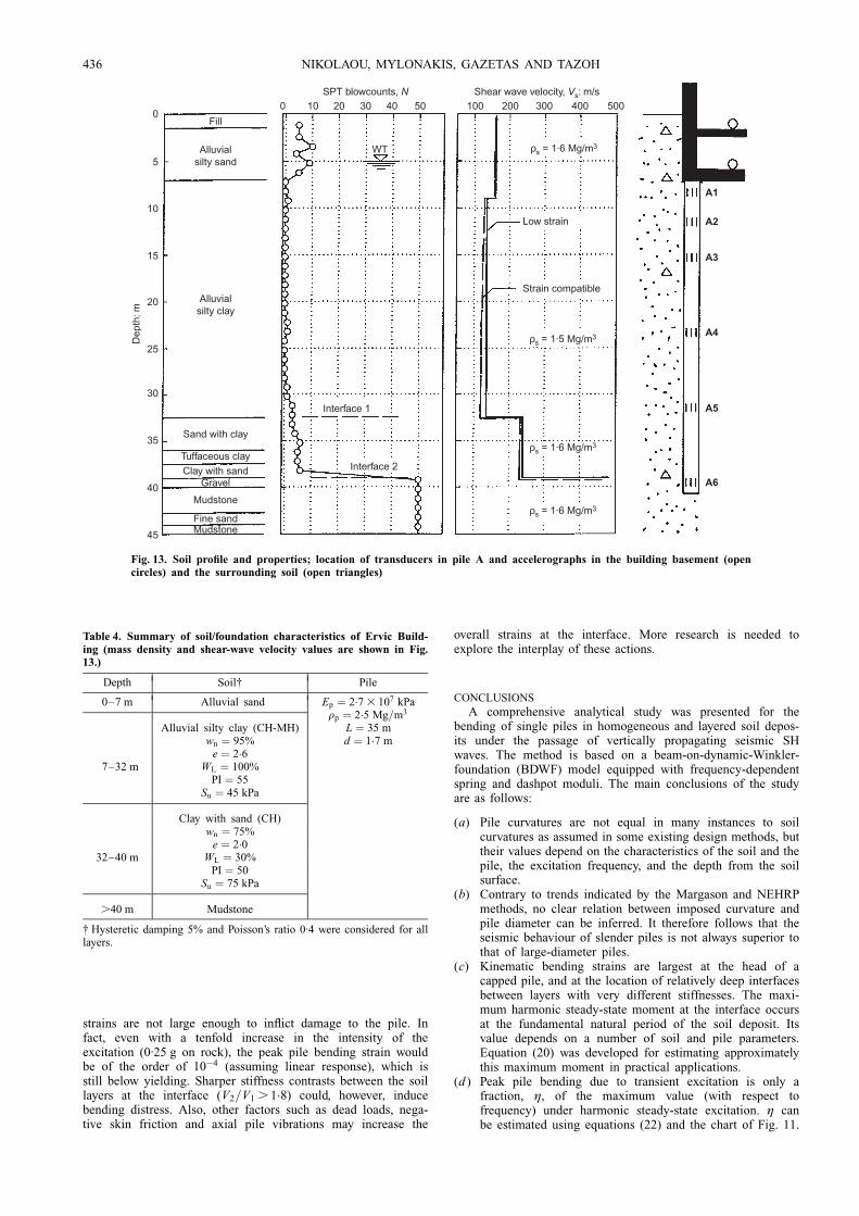
The soil pro®le is shown in Fig. 13. It consists of about 39 mof soft saturated high-plasticity silty clay (PI � 50) having ameasured shear wave velocity, Vs, ranging between 135 and240 m=s, underlain by stiff mudstone with Vs � 480 m=s. Thesevelocities are low-strain (Vs, max) values determined in situ usingPS logging (plank hammering method). Soil properties are alsolisted in Table 4. The earthquake event analysed here took placeunder the Tokyo Bay area (358129N; 1398489E) on 2 February1992 with a magnitude 5´9, focal depth 93 km, and epicentraldistance from the site 32 km. The largest acceleration recordedon the ground surface was about 0´05g.
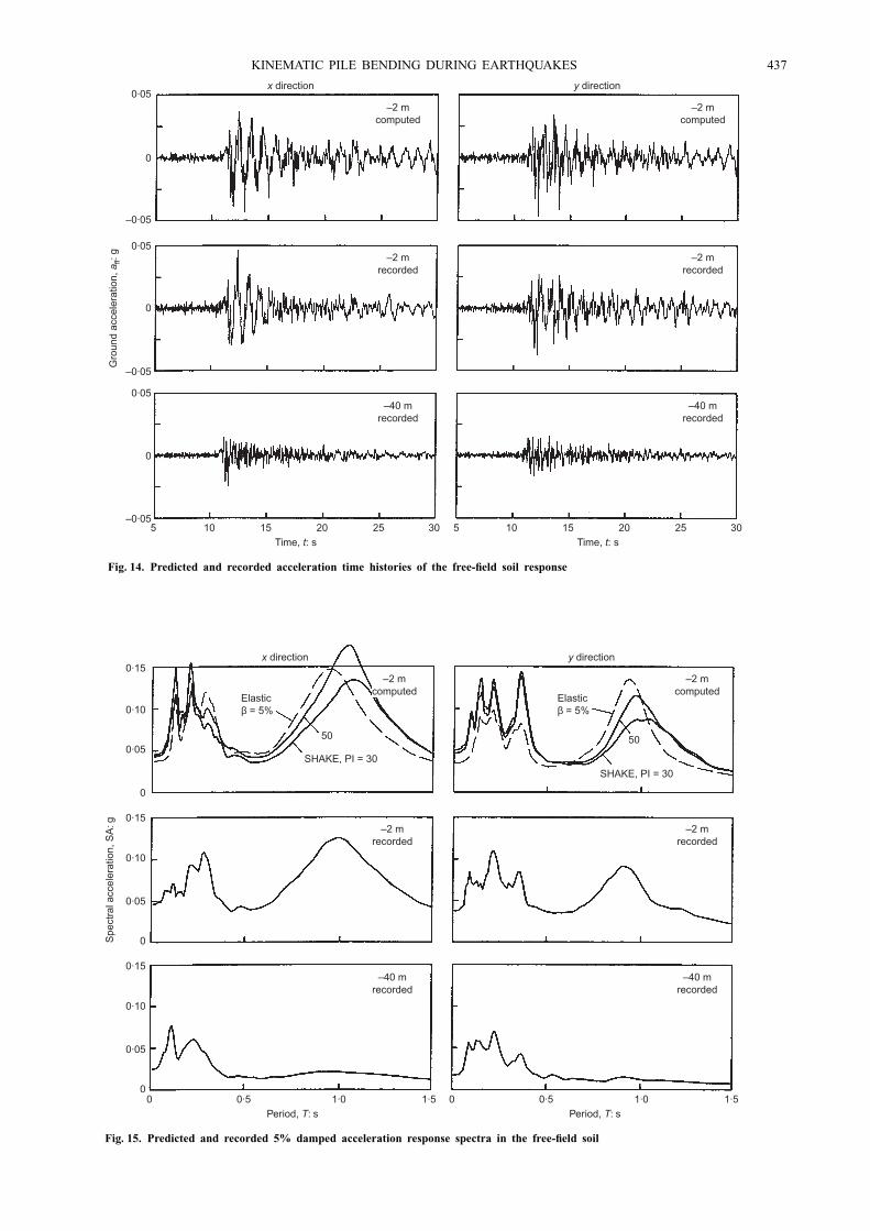
Acceleration time histories in the x and y directions justunder the ground surface (GLÿ 2 m) and the base mudstone(GLÿ 40 m) are plotted in Fig. 14. Their response spectra areshown in Fig. 15. Predictions using the equivalent-linear com-puter code SHAKE are also shown for comparison. Computedand recorded motions are in very good agreement despite thefact that in the theory the soil is modelled as a series ofperfectly horizontal layers subjected to vertically propagatingshear waves. The prevailing period of approximately 1 s obser-ved in the surface spectra is in agreement with the fundamentalnatural period of the soil layer: T1 � 4h=Vs � 4339=150 � 1 s. It is worth mentioning that because of therelatively low accelerations in the soil (ar � 0:025 g) and thehigh plasticity index of the material (PI � 50), the reduction insoil shear modulus predicted by SHAKE using the Vucetic &Dobry (1991) G±ã curves does not exceed a mere 10% (seeFig. 13). Similarly, soil damping is estimated to be about 3±4%. However, a slightly higher material damping of about 5%was found necessary to match the amplitude of accelerations atthe soil surface. To achieve this using the aforementioned G±ãcurves, a plasticity index PI � 30 had to be used (Fig. 15). Thissmall discrepancy can be attributed to the material character-istics of the clay. The G(ã), â(ã) curves for PI � 30 were usedthereafter.
The ratio of the recorded response spectra at the surface(ÿ2 m) and the base (ÿ40 m) of the pro®le is plotted in Fig.16, for both x and y directions. The substantial ampli®cation(about eight times) observed close to the fundamental naturalperiod of the pro®le is evident in the graph. The slightly higherfundamental natural period and smaller ampli®cation in the xdirection could be attributed to the stronger excitation imposedalong the x axis. The similar ampli®cation patterns observed inthe two directions lends further support to the assumption ofone-dimensionality of the wave propagation, as adopted in ouranalyses.
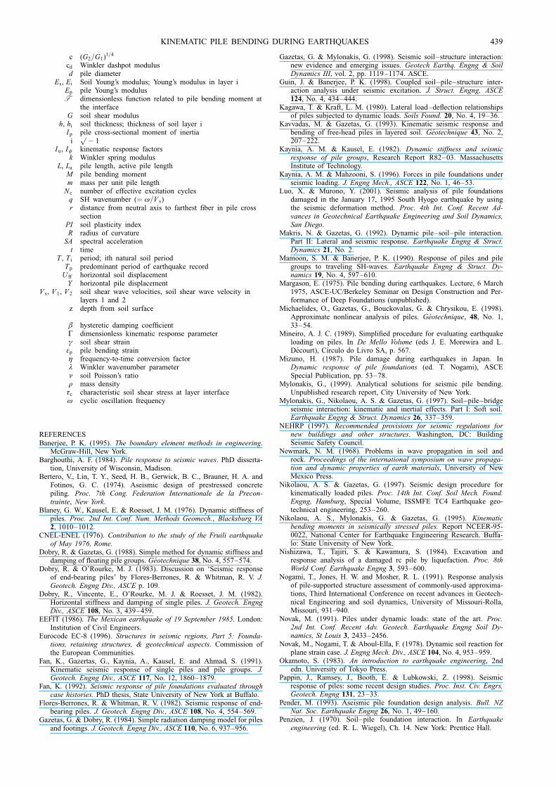
The computed and measured time histories of pile bendingstrain at the depth of 31 m (interface 1; see Fig. 13) arecompared in Fig. 17. Note that our method refers to a singlepile, and therefore the computed results for piles A and B areidentical (only one curve shown). Several interesting trends areworthy of note. First, the bending strains in the corner andcentre piles are very similar. This indicates that group effectsare minor for kinematic response, which is in agreement withthe analytical studies of Kaynia & Kausel (1982), Fan et al.(1991), Kaynia & Mahzooni (1996), and others. (By contrast,pile-to-pile interaction due to dynamic loading at the pile caphas been shown to have a profound effect on the response ofthe group; see Kaynia & Kausel (1982), Dobry & Gazetas(1988).) Second, the prevailing period of the records is veryclose to 1 s, which elucidates the role of soil response (asopposed to loading due to structural inertia forces) on thedevelopment of kinematic pile bending at depth. Third, thecomputed peak values tend to overestimate the measurementsby as much as 50%. While modelling errors are a `usualsuspect', this may also imply that the location of the straingauges might not be exactly at the interface between the twolayers, as was assumed in the analyses. Another possibility is
0
1
2
3
4
5
6
0 0·25 0·50 0·75 1·00 1·25Structural natural period, T: s
Spe
ctra
l am
plifi
catio
n
Pacoima, Whittier
LA116,Whittier
Tarzana, Whittier
Pacoima,Northridge
Pyrgos
JMA Kobe
La Villita, Mexico
Anderson, Loma Prieta
Fig. 9. Normalised 5%-damped spectra of the earthquake motionsconsidered
KINEMATIC PILE BENDING DURING EARTHQUAKES 433
that the stiffness contrast between the two layers may be lessthan the V2=V1 � 240=135 � 1:8 value assumed in our ana-lyses, thereby leading to smaller bending strain. Nevertheless,the agreement between the predicted and recorded time historiesis quite satisfactory from an engineering point of view.
The distributions along the pile of the peak values ofcomputed and measured bending strains are compared in Fig.18. The computed values are solely the result of loading fromthe surrounding soil (kinematic response): that is, the inertia ofthe superstructure is ignored. However, the measured values are,of course, the superposition of both kinematic (i.e. due to soil)and inertial (i.e. due to structure) strains. The results of thecomparison show that:
(a) Theory and reality are in reasonable accord at the fourdeeper elevations below the active pile length, estimated as(equation (19))
La � (1:5)(350)1=4(1:7) � 11 m (23)
The under-prediction by the analysis of the strains close tothe pile head is understood, as such bending strains arisemainly from structural loading.
(b) Kinematically induced bending strains are pronounced closeto interface 1. This con®rms the signi®cance of kinematicbending in deposits containing consecutive layers withsharply different stiffness.
0·8
0·6
0·4
0·2
00
Least-square fitted lines
Data for T1 ≈ Tp (resonance)
Data for T1 ≠ Tp (non-resonance)
2 4 6
Number of 'effective' excitation cycles, Nc
η
0·04 Nc + 0·23
0·015 Nc + 0·17
Fig. 11. Proposed design curves for the frequency-to-time reductionfactor ç as a function of the number of `effective' excitation cyclesand resonance conditions. The dots correspond to the motionsshown in the legend of Fig. 10 and in Fig. 9
0
5
10
15
Dep
th, z
: m
0
5
10
25
15
20
Dep
th, z
: m
Dep
th, z
: m
0
5
10
15
20
25
0 5 10 15
0 5 10 20150 2010 30
Pile bending strain, εp: 10–4
BostonSoft clay
Bay Area
Steady state
Pacoima, Whittier
Artificial, EC8
Tarzana, Whittier
LA116, Whittier
Pacoima, Northridge
Anderson, Loma Prieta
JMA, Kobe
La villita
Pyrgos
Fig. 10. Comparison of envelopes of pile bending strains for various earthquake motions, plotted against themaximum steady-state strains, for four different soil pro®les (scaling to 0´2 g peak rock acceleration wasconsidered for all motions)
434 NIKOLAOU, MYLONAKIS, GAZETAS AND TAZOH
(c) Strains at the (even sharper) interface 2 are less pronouncedin our analysis because of the lack of adequate pile lengthbelow the interface to mobilise bending moments. Unfortu-nately, the authors could not ®nd a convincing explanationfor the relatively high strain recorded at that depth in the ydirection.
Computation of kinematic pile bending strain using equations(20)-(22)
As an example, the peak kinematic bending strain at inter-face 1 (i.e. at z � 31 m) will be computed using the approx-imate method proposed in equations (20)±(22). For simplicity,only the strain in the x direction (along which the excitation isstronger) will be analysed. It will be shown that realisticestimates of the response can be obtained using this simpli®edapproach.
The characteristic stress at the interface is computed fromequation (20a):
ôc � (0:045 3 9:81) 3 1:55 3 31 � 21 kPa (24)
The pile±soil stiffness contrast is approximately
Ep
E1
' 2:7 3 107
1352 3 1:5 3 2 3 (1� 0:4)' 350 (25)
where 0´4 is an approximate estimate of the Poisson's ratio ofthe clay. The pile slenderness ratio and stiffness contrast atinterface 1 are, respectively,
L=d � 34:9=1:7 ' 20:5 (26)
V2=V1 � 240=135 ' 1:78 (27)
The resonant pile bending moment is obtained using equation(20a):
M � 0:042 3 21 3 1:73 3 20:50:3 3 3500:65 3 1:780:5
� 650 kNm (28)
which corresponds to bending around the y axis.Assuming non-resonant conditions (a reasonable approxima-
tion in view of the well-separated predominant periods of thebedrock motion (� 0:1±0:3 s) and fundamental natural period ofthe soil layer (� 1 s)), and about three to four effective excita-tion cycles, the frequency-to-time conversion factor ç is ap-proximately (equation (22b), Fig. 11)
ç � 0:015 3 3� 0:17 � 0:22 (29)
From equation (21), the peak bending moment at the interfaceis
max M(t) � 0:21 3 650 � 143 kN m (30)
Finally, the peak bending strain in the pile is obtained throughequation (18).
åp � 143=(2:7 3 107 3 0:41) 3 1:7=2 � 1:1 3 10ÿ5 (31)
which is in accordance with the recorded values in Fig. 18.As a ®nal remark, we should point out that the recorded peak
28·4 m
24·8 m
28·4 m
24·8
m
RF
7F
B1F
46·6
m
GL
SoilStrain
transducer
Supportinglayer
GL –39 m Pile A
Pile A
Pile B
Pile B
d
c
b
z
yx
x
y
a
Building accelerometer
0 10
Ground accelerometer
Dynamic strain transducer
y (+)
x (+)
Scale: m
Fig. 12. Arrangement of accelerometers and strain gauges at Ervic Building
KINEMATIC PILE BENDING DURING EARTHQUAKES 435
strains are not large enough to in¯ict damage to the pile. Infact, even with a tenfold increase in the intensity of theexcitation (0´25 g on rock), the peak pile bending strain wouldbe of the order of 10ÿ4 (assuming linear response), which isstill below yielding. Sharper stiffness contrasts between the soillayers at the interface (V2=V1 . 1:8) could, however, inducebending distress. Also, other factors such as dead loads, nega-tive skin friction and axial pile vibrations may increase the
overall strains at the interface. More research is needed toexplore the interplay of these actions.
CONCLUSIONS
A comprehensive analytical study was presented for thebending of single piles in homogeneous and layered soil depos-its under the passage of vertically propagating seismic SHwaves. The method is based on a beam-on-dynamic-Winkler-foundation (BDWF) model equipped with frequency-dependentspring and dashpot moduli. The main conclusions of the studyare as follows:
(a) Pile curvatures are not equal in many instances to soilcurvatures as assumed in some existing design methods, buttheir values depend on the characteristics of the soil and thepile, the excitation frequency, and the depth from the soilsurface.
(b) Contrary to trends indicated by the Margason and NEHRPmethods, no clear relation between imposed curvature andpile diameter can be inferred. It therefore follows that theseismic behaviour of slender piles is not always superior tothat of large-diameter piles.
(c) Kinematic bending strains are largest at the head of acapped pile, and at the location of relatively deep interfacesbetween layers with very different stiffnesses. The maxi-mum harmonic steady-state moment at the interface occursat the fundamental natural period of the soil deposit. Itsvalue depends on a number of soil and pile parameters.Equation (20) was developed for estimating approximatelythis maximum moment in practical applications.
(d ) Peak pile bending due to transient excitation is only afraction, ç, of the maximum value (with respect tofrequency) under harmonic steady-state excitation. ç canbe estimated using equations (22) and the chart of Fig. 11.
0
5
10
15
20
25
30
35
40
45
Dep
th: m
Fill
Alluvialsilty sand
Alluvialsilty clay
Sand with clay
Tuffaceous clayClay with sand
Gravel
Mudstone
MudstoneFine sand
Interface 2
Interface 1
WT
SPT blowcounts, N Shear wave velocity, Vs: m/s0 10 20 30 40 50 100 200 300 500400
ρs = 1·6 Mg/m3
ρs = 1·5 Mg/m3
Low strain
Strain compatible
ρs = 1·6 Mg/m3
ρs = 1·6 Mg/m3
A1
A2
A3
A4
A5
A6
Fig. 13. Soil pro®le and properties; location of transducers in pile A and accelerographs in the building basement (opencircles) and the surrounding soil (open triangles)
Table 4. Summary of soil/foundation characteristics of Ervic Build-ing (mass density and shear-wave velocity values are shown in Fig.13.)
Depth Soil{ Pile
0±7 m Alluvial sand Ep � 2:7 3 107 kParp � 2:5 Mg=m3
Alluvial silty clay (CH-MH) L � 35 mwn � 95% d � 1:7 m
e � 2:67±32 m WL � 100%
PI � 55Su � 45 kPa
Clay with sand (CH)wn � 75%
e � 2:032±40 m WL � 30%
PI � 50Su � 75 kPa
.40 m Mudstone
{ Hysteretic damping 5% and Poisson's ratio 0´4 were considered for alllayers.
436 NIKOLAOU, MYLONAKIS, GAZETAS AND TAZOH
0
0·05
0·15
0·10
0
0·05
0·15
0·10
0
0·05
0·15
0·10
–40 mrecorded
–40 mrecorded
–2 mrecorded
–2 mrecorded
–2 mcomputed
–2 mcomputed
0 0·5 1·0 1·5Period, T: s
0 0·5 1·0 1·5Period, T: s
Spe
ctra
l acc
eler
atio
n, S
A: g
x direction y direction
SHAKE, PI = 30SHAKE, PI = 30
50 50
Elasticβ = 5%
Elasticβ = 5%
Fig. 15. Predicted and recorded 5% damped acceleration response spectra in the free-®eld soil
0·05
0
0
0
–0·05
0·05
–0·05
0·05
–0·05
–40 mrecorded
–40 mrecorded
–2 mrecorded
–2 mrecorded
–2 mcomputed
–2 mcomputed
10 15 20 3025Time, t: s
55 10 15 20 3025Time, t: s
Gro
und
acce
lera
tion,
aff:
g
x direction y direction
Fig. 14. Predicted and recorded acceleration time histories of the free-®eld soil response
KINEMATIC PILE BENDING DURING EARTHQUAKES 437
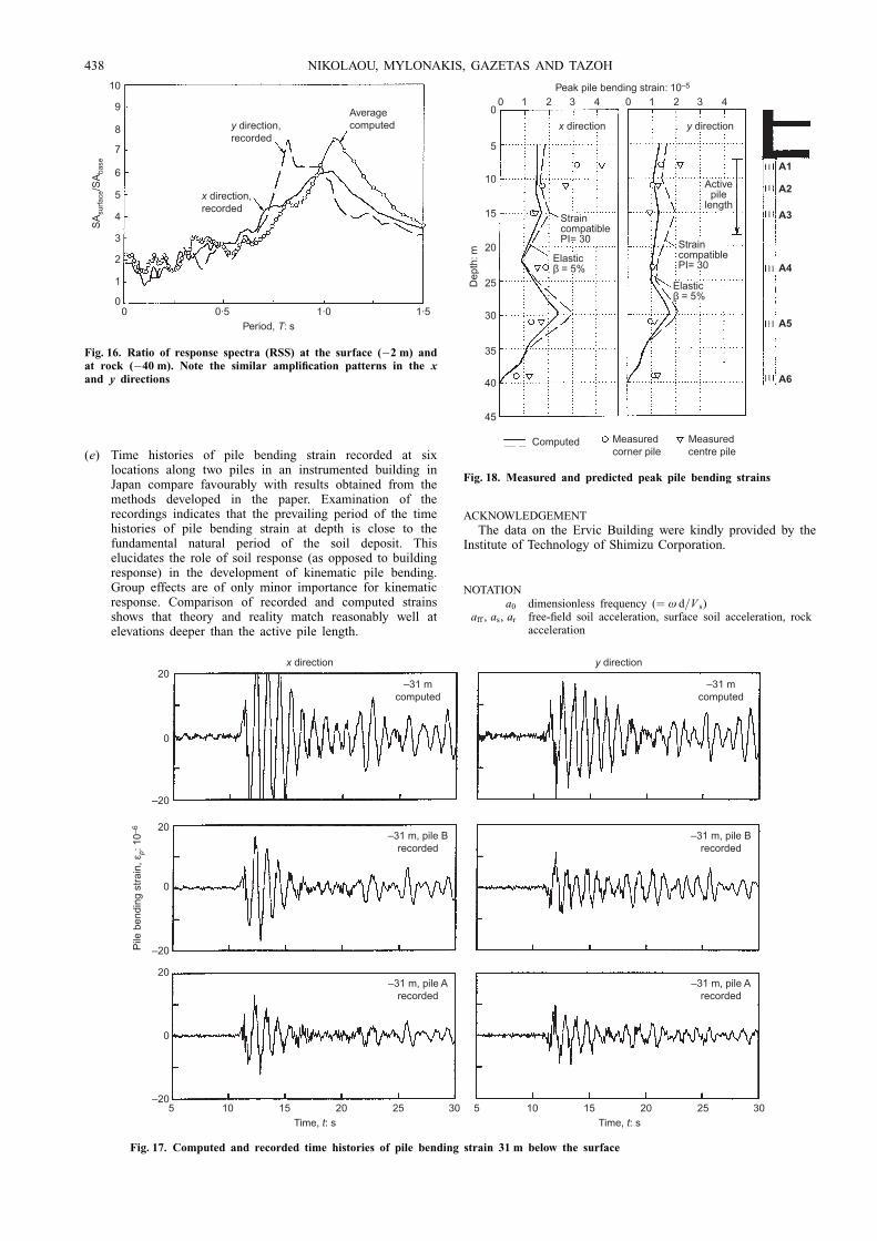
(e) Time histories of pile bending strain recorded at sixlocations along two piles in an instrumented building inJapan compare favourably with results obtained from themethods developed in the paper. Examination of therecordings indicates that the prevailing period of the timehistories of pile bending strain at depth is close to thefundamental natural period of the soil deposit. Thiselucidates the role of soil response (as opposed to buildingresponse) in the development of kinematic pile bending.Group effects are of only minor importance for kinematicresponse. Comparison of recorded and computed strainsshows that theory and reality match reasonably well atelevations deeper than the active pile length.
ACKNOWLEDGEMENT
The data on the Ervic Building were kindly provided by theInstitute of Technology of Shimizu Corporation.
NOTATIONa0 dimensionless frequency (� ù d=V s)
aff , as, ar free-®eld soil acceleration, surface soil acceleration, rockacceleration
0
1
2
3
4
5
6
7
8
9
10
0
Average computedy direction,
recorded
x direction,recorded
0·5 1·0 1·5Period, T: s
SA
surfa
ce/S
Aba
se
Fig. 16. Ratio of response spectra (RSS) at the surface (ÿ2 m) andat rock (ÿ40 m). Note the similar ampli®cation patterns in the xand y directions
20
0
0
0
–20
20
–20
20
–20
–31 m, pile Brecorded
–31 m, pile Brecorded
–31 m, pile Arecorded
–31 m, pile Arecorded
–31 mcomputed
–31 mcomputed
10 15 20 3025Time, t: s
55 10 15 20 3025Time, t: s
Pile
ben
ding
str
ain,
εp:
10–
6
x direction y direction
Fig. 17. Computed and recorded time histories of pile bending strain 31 m below the surface
0
5
10
15
20
25
30
35
40
45
Dep
th: m
A1
A2
A3
A4
A5
A6
0
StraincompatiblePI= 30
Computed Measuredcorner pile
Measuredcentre pile
StraincompatiblePI= 30
Elasticβ = 5%
Elasticβ = 5%
1 2 3 4 0 1 2 3 4Peak pile bending strain: 10–5
x direction y direction
Activepile
length
Fig. 18. Measured and predicted peak pile bending strains
438 NIKOLAOU, MYLONAKIS, GAZETAS AND TAZOH
c (G2=G1)1=4
cd Winkler dashpot modulusd pile diameter
Es, Ei Soil Young's modulus; Young's modulus in layer iEp pile Young's modulusF dimensionless function related to pile bending moment at
the interfaceG soil shear modulus
h, hi soil thickness; thickness of soil layer iIp pile cross-sectional moment of inertia
ip ÿ 1
Iu, Iö kinematic response factorsk Winkler spring modulus
L, La pile length, active pile lengthM pile bending momentm mass per unit pile length
N c number of effective excitation cyclesq SH wavenumber (� ù=V s)r distance from neutral axis to farthest ®ber in pile cross
sectionPI soil plasticity indexR radius of curvature
SA spectral accelerationt time
T , T i period; ith natural soil periodTp predominant period of earthquake record
U ff horizontal soil displacementY horizontal pile displacement
V s, V 1, V 2 soil shear wave velocities, soil shear wave velocity inlayers 1 and 2
z depth from soil surface
â hysteretic damping coef®cientà dimensionless kinematic response parameterã soil shear strainåp pile bending strainç frequency-to-time conversion factorë Winkler wavenumber parameterí soil Poisson's ratior mass densityôc characteristic soil shear stress at layer interfaceù cyclic oscillation frequency
REFERENCESBanerjee, P. K. (1995). The boundary element methods in engineering.
McGraw-Hill, New York.Barghouthi, A. F. (1984). Pile response to seismic waves. PhD disserta-
tion, University of Wisconsin, Madison.Bertero, V., Lin, T. Y., Seed, H. B., Gerwick, B. C., Brauner, H. A. and
Fotinos, G. C. (1974). Aseismic design of prestressed concretepiling. Proc. 7th Cong. Federation Internationale de la Precon-trainte, New York.
Blaney, G. W., Kausel, E. & Roesset, J. M. (1976). Dynamic stiffness ofpiles. Proc. 2nd Int. Conf. Num. Methods Geomech., Blacksburg VA2, 1010±1012.
CNEL-ENEL (1976). Contribution to the study of the Fruili earthquakeof May 1976, Rome.
Dobry, R. & Gazetas, G. (1988). Simple method for dynamic stiffness anddamping of ¯oating pile groups. GeÂotechnique 38, No. 4, 557±574.
Dobry, R. & O'Rourke, M. J. (1983). Discussion on `Seismic responseof end-bearing piles' by Flores-Berrones, R. & Whitman, R. V. J.Geotech. Engng Div., ASCE p. 109.
Dobry, R., Vincente, E., O'Rourke, M. J. & Roesset, J. M. (1982).Horizontal stiffness and damping of single piles. J. Geotech. EngngDiv., ASCE 108, No. 3, 439±459.
EEFIT (1986). The Mexican earthquake of 19 September 1985. London:Institution of Civil Engineers.
Eurocode EC-8 (1996). Structures in seismic regions, Part 5: Founda-tions, retaining structures, & geotechnical aspects. Commission ofthe European Communities.
Fan, K., Gazertas, G., Kaynia, A., Kausel, E. and Ahmad, S. (1991).Kinematic seismic response of single piles and pile groups. J.Geotech. Engng Div., ASCE 117, No. 12, 1860±1879.
Fan, K. (1992). Seismic response of pile foundations evaluated throughcase histories. PhD thesis, State University of New York at Buffalo.
Flores-Berrones, R. & Whitman, R. V. (1982). Seismic response of end-bearing piles. J. Geotech. Engng Div., ASCE 108, No. 4, 554±569.
Gazetas, G. & Dobry, R. (1984). Simple radiation damping model for pilesand footings. J. Geotech. Engng Div., ASCE 110, No. 6, 937±956.
Gazetas, G. & Mylonakis, G. (1998). Seismic soil±structure interaction:new evidence and emerging issues. Geotech Earthq. Engng & SoilDynamics III, vol. 2, pp. 1119±1174. ASCE.
Guin, J. & Banerjee, P. K. (1998). Coupled soil±pile±structure inter-action analysis under seismic excitation. J. Struct. Engng, ASCE124, No. 4, 434±444.
Kagawa, T. & Kraft, L. M. (1980). Lateral load±de¯ection relationshipsof piles subjected to dynamic loads. Soils Found. 20, No. 4, 19±36.
Kavvadas, M. & Gazetas, G. (1993). Kinematic seismic response andbending of free-head piles in layered soil. GeÂotechnique 43, No. 2,207±222.
Kaynia, A. M. & Kausel, E. (1982). Dynamic stiffness and seismicresponse of pile groups, Research Report R82±03. MassachusettsInstitute of Technology.
Kaynia, A. M. & Mahzooni, S. (1996). Forces in pile foundations underseismic loading. J. Engng Mech., ASCE 122, No. 1, 46±53.
Luo, X. & Murono, Y. (2001). Seismic analysis of pile foundationsdamaged in the January 17, 1995 South Hyogo earthquake by usingthe seismic deformation method. Proc. 4th Int. Conf. Recent Ad-vances in Geotechnical Earthquake Engineering and Soil Dynamics,San Diego.
Makris, N. & Gazetas, G. (1992). Dynamic pile±soil±pile interaction.Part II: Lateral and seismic response. Earthquake Engng & Struct.Dynamics 21, No. 2.
Mamoon, S. M. & Banerjee, P. K. (1990). Response of piles and pilegroups to traveling SH-waves. Earthquake Engng & Struct. Dy-namics 19, No. 4, 597±610.
Margason, E. (1975). Pile bending during earthquakes. Lecture, 6 March1975, ASCE-UC/Berkeley Seminar on Design Construction and Per-formance of Deep Foundations (unpublished).
Michaelides, O., Gazetas, G., Bouckovalas, G. & Chrysikou, E. (1998).Approximate nonlinear analysis of piles. GeÂotechnique, 48, No. 1,33±54.
Mineiro, A. J. C. (1989). Simpli®ed procedure for evaluating earthquakeloading on piles. In De Mello Volume (eds J. E. Morewira and L.DeÂcourt), CõÂrculo do Livro SA, p. 567.
Mizuno, H. (1987). Pile damage during earthquakes in Japan. InDynamic response of pile foundations (ed. T. Nogami), ASCESpecial Publication, pp. 53±78.
Mylonakis, G., (1999). Analytical solutions for seismic pile bending.Unpublished research report, City University of New York.
Mylonakis, G., Nikolaou, A. S. & Gazetas, G. (1997). Soil±pile±bridgeseismic interaction: kinematic and inertial effects. Part I: Soft soil.Earthquake Engng & Struct. Dynamics 26, 337±359.
NEHRP (1997). Recommended provisions for seismic regulations fornew buildings and other structures. Washington, DC: BuildingSeismic Safety Council.
Newmark, N. M. (1968). Problems in wave propagation in soil androck. Proceedings of the international symposium on wave propaga-tion and dynamic properties of earth materials, University of NewMexico Press.
Nikolaou, A. S. & Gazetas, G. (1997). Seismic design procedure forkinematically loaded piles. Proc. 14th Int. Conf. Soil Mech. Found.Engng, Hamburg, Special Volume, ISSMFE TC4 Earthquake geo-technical engineering, 253±260.
Nikolaou, A. S., Mylonakis, G. & Gazetas, G. (1995). Kinematicbending moments in seismically stressed piles. Report NCEER-95-0022, National Center for Earthquake Engineering Research. Buffa-lo: State University of New York.
Nishizawa, T., Tajiri, S. & Kawamura, S. (1984). Excavation andresponse analysis of a damaged rc pile by liquefaction. Proc. 8thWorld Conf. Earthquake Engng 3, 593±600.
Nogami, T., Jones, H. W. and Mosher, R. L. (1991). Response analysisof pile-supported structure assessment of commonly-used approxima-tions, Third International Conference on recent advances in Geotech-nical Engineering and soil dynamics, University of Missouri-Rolla,Missouri, 931±940.
Novak, M. (1991). Piles under dynamic loads: state of the art. Proc.2nd Int. Conf. Recent Adv. Geotech. Earthquake Engng Soil Dy-namics, St Louis 3, 2433±2456.
Novak, M., Nogami, T. & Aboul-Ella, F. (1978). Dynamic soil reaction forplane strain case. J. Engng Mech. Div., ASCE 104, No. 4, 953±959.
Okamoto, S. (1983). An introduction to earthquake engineering, 2ndedn. University of Tokyo Press.
Pappin, J., Ramsey, J., Booth, E. & Lubkowski, Z. (1998). Seismicresponse of piles: some recent design studies. Proc. Inst. Civ. Engrs,Geotech. Engng 131, 23±33.
Pender, M. (1993). Aseismic pile foundation design analysis. Bull. NZNat. Soc. Earthquake Engng 26, No. 1, 49±160.
Penzien, J. (1970). Soil±pile foundation interaction. In Earthquakeengineering (ed. R. L. Wiegel), Ch. 14. New York: Prentice Hall.
KINEMATIC PILE BENDING DURING EARTHQUAKES 439

Poulos, H. G. & Davis, E. H. (1980). Pile foundation analysis anddesign. John Wiley & Sons.
Randolph, M. F. (1981). The response of ¯exible piles to lateral loading.GeÂotechnique 31, No. 2, 247±259.
Roesset, J. M. (1977). (eds C. S. Desar and J. T. Christian). Soilampli®cation of earthquakes. Numerical Methods in GeotechnicalEngineering, McGraw-Hill, 639±682.
Roesset, J. M. (1980). Stiffness and damping coef®cients of foundations.Proc ASCE Geotech. Engng Div. Nat. Conv. 3, 1±30.
Ross, G. A., Seed, H. B. & Migliaccio, R. (1969). Bridge foundations inthe Alaska earthquake. J. Soil Mech. Found. Engng, ASCE, 95.
Schnabel, P. B., Lysmer, J. & Seed, H. B., (1972). SHAKE: A computerprogram for earthquake response analysis of horizontally layeredsites, EERC 72-12. Berkeley: University of California.
Scott, R. F. (1981). Foundation Analysis, Prentice Hall, New York.Sheta, M. and Novak, M. (1982). Vertical vibration of pile groups,
Journal of the Geotechnical Engineering Division, ASCE, 108, GT4,570±590.
Tajimi, H. (1969). Dynamic analysis of structure embedded in elasticstratum. Proc. 4th World Conf. Earthquake Engng, Santiago, 53±69.
Tazoh, T., Shimizu, K. & Wakahara, T. (1987). Seismic observationsand analysis of grouped piles. In Dynamic response of pile founda-tions: experiment, analysis and observation, Geotechnical SpecialPublication No. 11. ASCE.
Technical Council on Lifeline Earthquake Engineering (TCLEE) (1998).Seismic guidelines for ports (ed. S. D. Werner). ASCE.
Veletsos, A. S. & Dotson, K. W. (1986). Impedances of soil layer withdisturbed boundary zone. J. Geotechn. Engng, ASCE 112, No. 3.
Veletsos, A. S. & Ventura, C. E. (1984). Ef®cient analysis of dynamicresponse of linear systems. Earthquake Engng & Struct. Dynamics12, 521±536.
Velez, A., Gazetas, G. & Khrishnan, R. (1983). Lateral dynamicresponse of constrained-head piles. J. Geotech. Engng Div., ASCE109, No. 8, 1063±1081.
Vucetic, M. and Dobry, R. (1991). Effect of soil plasticity on cyclicresponse. J. Geotech. Engng Div., ASCE 117, No. 1, 89±107.
440 NIKOLAOU, MYLONAKIS, GAZETAS AND TAZOH
Related Documents