UNDERGROUND HYDRAULIC CAR PARKING SYSTEM A Project Report Submitted in partial fulfillment for the Award of the degree of BACHELOR OF TECHNOLOGY In MECHANICAL ENGINEERING Submitted by AJAY KUMAR SHARMA (1264540003) AKHILANAND YADAV (1264540009) NITESH RAJ SRIVASTAVA (1264540049) SANDEEP MAURYA (1264540065) SANDIP SHARMA (1264540066) Under the Guidance of Mr. K. K. GUPTA IDEAL INSTITUTE OF MANAGEMENT & TECHNOLOGY, GZB DR. A.P.J. ABDUL KALAM TECHNICAL UNIVERSITY, LUCKNOW 2015-2016

Welcome message from author
This document is posted to help you gain knowledge. Please leave a comment to let me know what you think about it! Share it to your friends and learn new things together.
Transcript

UNDERGROUND HYDRAULIC CAR PARKING SYSTEM
A Project Report
Submitted in partial fulfillment for the
Award of the degree of
BACHELOR OF TECHNOLOGY
In
MECHANICAL ENGINEERING
Submitted by
AJAY KUMAR SHARMA (1264540003)
AKHILANAND YADAV (1264540009)
NITESH RAJ SRIVASTAVA (1264540049)
SANDEEP MAURYA (1264540065)
SANDIP SHARMA (1264540066)
Under the Guidance of
Mr. K. K. GUPTA
IDEAL INSTITUTE OF MANAGEMENT & TECHNOLOGY, GZB
DR. A.P.J. ABDUL KALAM TECHNICAL UNIVERSITY, LUCKNOW
2015-2016

i
DECLARATION
We hereby declare that this submission is our own work to the best of our knowledge
and belief, it contains no material previously or written by any other person nor
material which to a substantial extent has been accepted for the award of any degree or
diploma of the university or other institute of higher learning, except where due
acknowledgment and references has been made in the text.
NAME ROLL NUMBER SIGNATURE
AJAY KUMAR SHARMA 1264540003
AKHILANAND YADAV 1264540009
NITESH RAJ SRIVASTAVA 1264540049
SANDEEP MAURYA 1264540065
SANDIP SHARMA 1264540066
Date:-

ii
CERTIFICATE
This is to certify that project report entitled “UNDERGROUND HYDRAULIC CAR
PARKING SYSTEM” which is being submitted by Nitesh Raj Srivastava, Sandeep
Maurya, Sandip Sharma, Ajay Kumar Sharma, Akhilanand Yadav in partial
fulfillment for the requirement for the award of the degree of Bachelor of Technology
in department of Mechanical Engineering of Ideal Institute of Management and
Technology, Ghaziabad (Dr. A.P.J. Abdul Kalam Technical University). They have
worked under the guidance of Mr. K. K. Gupta (Asst. Prof., Department of
Mechanical Engineering) and have fulfilled the requirement for the submission of the
project. The matter embodied in this thesis is original and has not been submitted for
the award of any other degree.
Supervisor Head of Department
Mr. K. K. Gupta Mr. K. K. Gupta
Assistant Professor Deptt. of Mech. Engg.
Deptt. of Mech. Engg. IIMT, GZB
Date:-
iii
ACKNOWLEDGEMENT
First of all I would like to thank the almighty God for listening my prayers and giving
me strength to complete the dissertation work.
I would like to express a deep sense of gratitude and thanks profusely to Mr. K. K.
Gupta Assistant Professor, Department of Mechanical Engineering Ideal Institute of
Management and Technology, Ghaziabad (U.P.), my guides and mentors, without the
wise counsel and able guidance, it would have been impossible to complete the
dissertation in this manner.
I am also grateful to Ideal Institute of Management and Technology, Ghaziabad,
especially Department of Mechanical Engineering for extending all facilities and
cooperation to me for carrying out this work. I shall be failing in my duty if I don’t
acknowledge the support received from Mr. K. K. Gupta, Department of Mechanical
Engineering, IIMT, Ghaziabad (U.P.) in order to complete my work.
I must also express my deep regards and thanks to my parents for supporting and
boosting my morale so that I can overcome my hard times. I also want to thanks my
senior & my friend Mr. Ashutosh Verma and Abhishek Maurya Department of
Mechanical Engineering, IIT, Ghaziabad (U.P.). There are two person helped me a lot
in order to complete my thesis work.
I finally pray that Almighty fulfils the aspirations of all the people who have been a
part of this journey and those who will be a part of future journeys.
NAME ROLL NUMBER SIGNATURE
AJAY KUMAR SHARMA (1264540003)
AKHILANAND YADAV (1264540009)
NITESH RAJ SRIVASTAVA (1264540049)
SANDEEP MAURYA (1264540065)
SANDIP SHARMA (1264540066)
Date:-
iv
ABSTRACT
Underground Hydraulic Car Parking System is a mechanical device that multiplies
parking capacity inside a parking lot. This parking system is generally powered
by electric motors or hydraulic pumps that move vehicles into a storage position. The
project is based on Pascal’s law which is simple in working and due to incompressible
fluid used as transmitting medium for pressure, it is noiseless.
Our Multi- storey car park systems are less expensive per parking slot, since they tend
to require less building volume and less ground area than a conventional facility with
the same capacity. Underground Car parking systems garage systems
reduce pollution because cars are not running or turning around while drivers look for
parking spaces.
The limitation of this project is that, it can only be used for domestic purpose in urban
areas. The cost of project is not much more, so it can utilize by rich family as well as
middle class family. Finally an Underground Hydraulic Car Parking System is a way to
parking a car or multiple cars in a limited space. It also provides security and safety of
cars in low cost of parking.

v
NOMENCLATURE
Symbol Description
D Dia. of master cylinder
A Cross-section area of master cylinder
d Bore of pillar cylinder
a Cross-section area of pillar cylinder
ae Equivalent cross-section area of pillar cylinder
L Stroke length of master cylinder
l Stroke length of pillar cylinder
Tps Torque produced at pinion shaft
Tin Torque produced at gearbox input
Fin Force produced by motor
rm Radius of motor gear
dg Effective dia. of gear
Pm Motor power
f Force exerted on the pillar piston
F Master cylinder force
W Work done by master cylinder
dp Dia. of pinion
Le Effective distance between pinion and motor shaft
Nm Newton meter
Hp Horsepower
rpm Revolution per minute
∆P Hydrostatic pressure
ρ Density of fluid
g Acceleration due to gravity
∆h Fluid depth from the surface
IMA Mechanical advantage
vi
TABLE OF CONTENT
Declaration i
Certificate ii
Acknowledgement iii
Abstract iv
Nomenclature v
1. Introduction 1-7
1.1 Aim of Our Project 2
1.2 Inspiration to Construct this Project 3
1.3 Finding Parking Space is a Daily Struggle 4
1.4 Frustration and Ego Lead to Death 6
1.4.1 Parking Vehicle Inspired us to Construct this Project 7
2. Principle of Project 8-16
2.1 Pascal’s Law 8
2.2 Project based on Pascal’s Principle and Hydraulics 9
2.3 Explanation 11
2.4 Applications of Pascal’s Law 12
2.5 Line Diagram of UHCPS 13
2.6 Calculation 14
3. Components & Material Selection 17-27
3.1 Component Requirement 17
3.2 Component Details 18
3.2.1 Slow Speed Crouzet Motor Gear Box 18
3.2.2 Rack and Pinion 20
3.2.3 Sliding Channel 20
3.2.4 Bearing 608 21
3.2.4.1 Ball Bearing 22
3.2.5 Bearing Stand 22
3.2.6 Syringe 22
3.2.7 Pipe 23
3.2.8 Sliding Switch 23
3.2.9 Transformer 24
vii
3.2.10 Metal and Wooden Body Frame 24
3.2.11 Cut off Switch 24
3.2.12 T-junction 25
3.2.13 Diode 25
3.2.14 Glue Gun 25
3.2.15 Nut and Bolt 26
3.3 Cost of Component 26
4. Project Construction 28-37
4.1 Methodologies & Construction 28
4.2 About our Project 29
4.3 Project Construction Steps 29
4.4 Future Layout 33
4.5 Power Supply 34
4.5.1 AC to DC Supply 35
4.6 Theory 35
4.6.1 Rectification 35
4.6.2 Full Wave Rectifier 36
4.6.3 Bridge Rectifier 37
5. Fabrication of the Project 38-46
5.1 Cost of Components 46
6. Conclusion 47
7. Suggestion for Future Work 48
8. References 49
9. Appendix 50-51
viii
LIST OF FIGURE
1. Introduction 1-7
1.1 Electro-Hydraulic Parking System 1
1.2 Two Car Parking System 2
1.3 Car Parking Accident 3
1.4 Victim Rajinder Bhatia 3
1.5 Finding Parking Space in Daily Life 5
1.6 Underground Hydraulic Car Parking System 7
2. Principle of Project 8-16
2.1 Study of Pascal’s Law 8
2.2 Pascal’s Principle 10
2.3 Verification of Pascal’s Law 10
2.4 Line Diagram of UHCPS 13
3. Components and Material Selection 17-27
3.1a DC Motor 19
3.1b Rotation of Armature w.r.t. Stator 19
3.1c Rotation of Armature w.r.t. Stator 19
3.2 Rotation of a Pinion in a Rack Railway 20
3.3 Sliding Channel 20
3.4 Bearing 608 21
3.5 Tapered Roller Bearing from a Manual Transmission 21
3.6 Sectional view of a Ball Bearing 22
3.7 Bearing Stand 22
3.8 Syringe of 10mL 23
3.9 Syringe of 60mL 23
3.10 Pipe 23
3.11 Sliding Switch 23
3.12 Step-down Transformer 24
3.13 Wooden Block 24
3.14 Cut-off Switch 25
3.15 T-junction 25
3.16 Diode 25
3.17 Nut and Bolt 26

ix
4. Project Construction 28-37
4.1 Plastic Syringe 60mL 28
4.2 Transfer of Pressure through Fluid 29
4.3 Sliding Channel Arrangement 29
4.4 Fixing Sliding Channel on Wooden Base 30
4.5 Fixing Pinion Gear 30
4.6 Attachment of DC Gear Motor with Rod Shaft Gear 31
4.7 Sliding Mechanism 31
4.8 Car Lifting Platform Construction 32
4.9a Arrangement in Basement 32
4.9b Arrangement in Basement 33
4.10a Commercial Application of Project 33
4.10b Commercial Application of Project 34
4.10c Commercial Application of Project 34
4.11 Schematic of basic AC to DC Power Supply 35
4.12 Full Wave Rectifier 36
4.13 Bridge Rectifier 37
5. Fabrication of the Project 38-46
5.1 Making Wooden Block 38
5.2 Car Parking Platform 39
5.3 Arrangements for Lifting System 39
5.4 Fixing T-junction 39
5.5 Sliding Channel Arrangement 40
5.6 Welding of Rack on Iron Strip 40
5.7 Rack with Sliding Channel 40
5.8 Stopper 40
5.9 Backward & Forward Cut-off Switch 41
5.10 Pinion Arrangement 41
5.11 Gear Box with DC Motor 41
5.12 Bearing in Bearing Stand 42
5.13 Transformer Setting 42
5.14a Meshing Pinion & Rack 42
5.14b Arrangement of Bearing Stand 42

x
5.15a Connection of Sliding Channel 43
5.15b Master Syringe Arrangement 43
5.16 Two-way Sliding Switch 43
5.17a Rectifier & Wire Connections 44
5.17b Input Wire Connection 44
5.18a Final View of the Project 44
5.18b Final View of the Project 45
5.18c Final View of the Project 45

xi
LIST OF TABLE
2. Principle of Project 8-16
2.1 Input Parameters Required to Determination of Forces 14
2.2 Calculated Design Parameters 16
3. Components & Material Selection 17-27
3.1 Component Requirement with Specification & Quantity 18
3.2 Cost of Component 27
5. Fabrication of the Project 38-46
5.1 Total Cost of UHCPS 46
5.2 Tentative Cost of Actual UHCPS 46

1
CHAPTER-1
INTRODUCTION
These days what is the common question arise in all big metropolitan cities? And
Question is, I need my own conveyance for daily routine work but I am not sure
where to park this conveyance?
Less space for parking is common cause for neighbors fight.
Basically, we are trying to sort this problem by construct our final year project. This
innovative, space-saving car lift & storage system doubles your parking space by
putting your car underground. Whether you’ve got limited square footage or simply
prefer to store your vehicle safely, our project is electro-hydraulic mechanism lowers
or lifts your vehicle with the touch of a button as shown in fig. 1.1.
Fig. 1.1 Electro-Hydraulic Parking System
2
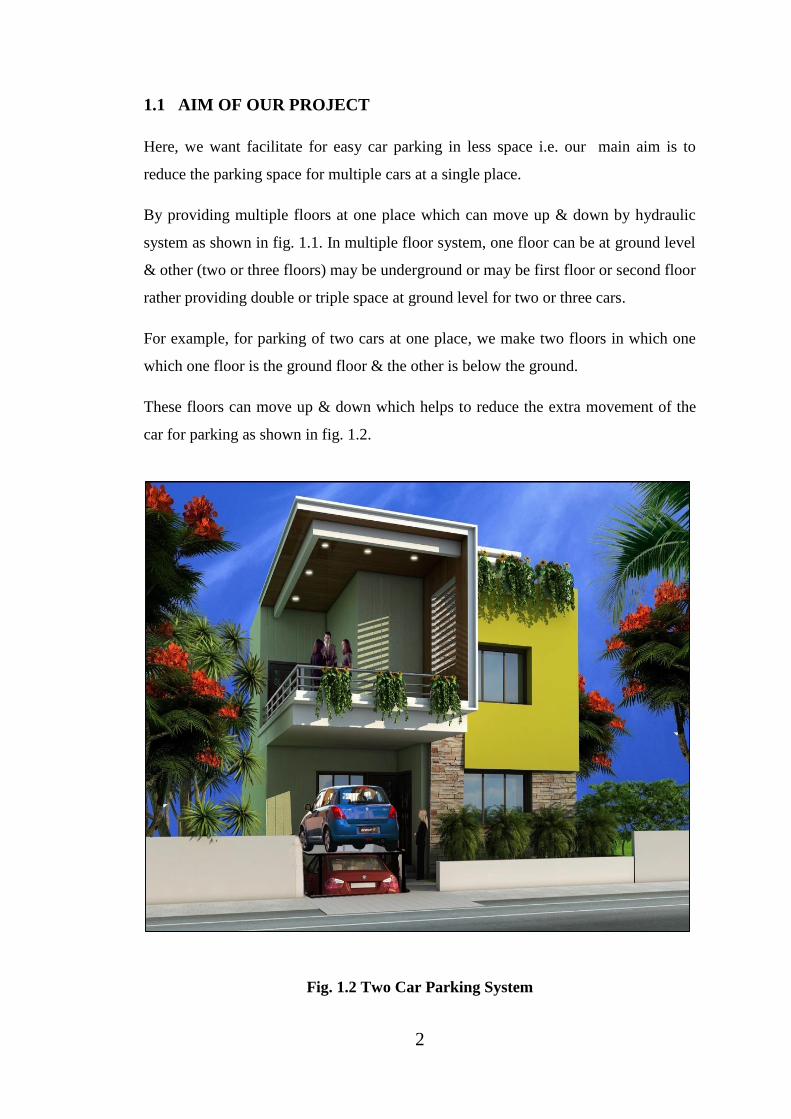
1.1 AIM OF OUR PROJECT
Here, we want facilitate for easy car parking in less space i.e. our main aim is to
reduce the parking space for multiple cars at a single place.
By providing multiple floors at one place which can move up & down by hydraulic
system as shown in fig. 1.1. In multiple floor system, one floor can be at ground level
& other (two or three floors) may be underground or may be first floor or second floor
rather providing double or triple space at ground level for two or three cars.
For example, for parking of two cars at one place, we make two floors in which one
which one floor is the ground floor & the other is below the ground.
These floors can move up & down which helps to reduce the extra movement of the
car for parking as shown in fig. 1.2.
Fig. 1.2 Two Car Parking System

3
1.2 INSPIRATION TO CONSTRUCT THIS PROJECT
Delhi Businessman, 57, Dies After Neighbours Beat Him in Row Over Parking
A 57-year-old businessman died on Sunday after he was allegedly thrashed inside his
home by neighbors and property dealers over a parking row in Central Delhi's West
Patel Nagar area. The victim Rajinder Bhatia owned a three-storey building and sold
his second floor to a man named Karthik Bhatia was with his family when Karthik
and two property dealers came to visit him to discuss an unresolved parking dispute.
Sleuths said Karthik had rented the second floor to another family, who had a tiff with
Bhatia's son Mokshit over car parking on Saturday night. Karthik, along with his
mother and local property dealers, came to meet Bhatia to resolve the squabble on
Sunday. Unfortunately, the discussion turned ugly and Bhatia was manhandled by the
visitors as shown in fig. 1.3 and 1.4.
Bhatia's wife and son Mokshit were unable to save him from the angry men. He was
declared brought dead by doctors at the BLK Hospital in Rajendra Palace.
Fig. 1.3 Car Parking Accident Fig. 1.4 Victim Rajinder Bhatia
Died of a Suspected Heart Attack
on the Way to Hospital
4
Investigators suspect that the victim might have suffered a cardiac arrest that led to his
death, as there was no injury marks on his body.
According to the victim's family, Karthik started beating Bhatia as soon as he entered
their room.
"The moment we opened the door Karthik started beating my father. He had come
with local property dealers, his mother and some other people. They hit father on his
chest and groin. Karthik's mother had threatened us in the past," Mokshit claimed.
Initially, the row over parking was solved between the two sides at the intervention of
their families.
"On Sunday morning, Bhatia was sitting in his home when around 11.25am, Karthik
along with his mother came to meet him. They started abusing each other and after
around 10 minutes, property dealers Ashok Oberoi and Dharmendra along with 10
others also reached there," a police officer said, adding that matters worsened
thereafter.
"During the clash, the victim suddenly fell on the ground. All the alleged persons fled
and the victim was taken to a nearby hospital where doctors declared him brought
dead," the police officer added.
Although other neighbors’ witnessed the scuffle, none tried to pacify the two sides.
The investigators ruled out use of any weapon during the scuffle.
Additional Commissioner of Police (Central) Alok Kumar said a case was registered
on the complaint of the victim's other son Mohit Bhatia.
"We are yet to confirm the reason behind Bhatia's death as he was only slapped and
pushed by the other party. We have arrested Karthik and Ashok Oberoi. All the
accused have been booked under Section 304 (culpable homicide not amounting to
murder) of the IPC," he added.
1.3 FINDING PARKING SPACE IS A DAILY STRUGGLE
In the congested lanes of a West Delhi neighborhood, finding space to park a vehicle
is a daily struggle which has led to small tiffs among residents many times.

5
But on Sunday morning one such scuffle led to the death of a businessman, allegedly
by the hand of someone he had sold a floor of his three-storey building.
Locals said that the issue of parking has increased over the last few years as more
house owners have started building multistory houses.
Many neighbors’ noted that while the number of people living in the area has
increased as house-owners started giving their floors up for rent, the space for parking
remains the same.
The issue of parking space has lead to verbal spats among neighbors’, but it had never
before lead to a violent incident in the area.
"As West Delhi became a popular destination for students and migrants, people here
started building multi storey buildings. Everyone here has at least a three floor house
but nobody cares about the space for parking as shown in fig. 1.5. You can construct
one floor over another but vehicles can only be parked on the road. Parking is a daily
problem for us," a resident said.
Fig. 1.5 Finding Parking Space in daily Life [1]
Many people said that they overlook the problems related to parking as they know
there is no solution in sight.

6
"What can be done? There are vehicles parked on both sides of the roads and in front
of our homes but still there is lack of space. There is no solution to it so we just let it
be," said Deepak, a neighbor of Rajendra Bhatia, who was allegedly killed on Sunday
after he had a tiff over the parking space. Neighbours describe Bhatia as a cordial and
silent man who mostly kept to himself. "He was very nice, cordial, and non
controversial. We never saw him fighting with anyone in the area. This is a shocking
incident as killing someone over lack of parking space is bizarre. It only shows how
aggressive people have become," a neighbor said.
1.4 FRUSTRATION AND EGO LEAD TO DEATH
Mail-Today spoke to Sameer Malhotra, director, Mental Health & Behavioural
Sciences at Max Healthcare.
He said: "It has become common to hear violent incidents happening over petty
matters. What leads a man or woman to become violent in the heat of moment may
differ from case to case, but it is primarily happening due to frustration and fragile
ego. "People have low frustration level these days which leads them into committing
avoidable mistakes.
"While every case of violence is different and there can be many reasons behind why
a person loses temper over small issues like parking space, driving on roads et cetera,
but the lack of tolerance among people is one of the main causes.
"The general level of stress has increased in our day-today life and people suffer from
high stress levels, especially in metropolitan cities.
"But despite all these factors, our coping abilities have not developed. We are seeing a
rise in number of people suffering from high frustration levels. At times, people don't
think about the results of their action while they are committing an act.
"People have become impatient and want everything as per their own wishes. Due to
their fragile egos, they feel hurt at even small incidents. So, a small tiff over parking
space or any other issue can hurt their sense of self if things do not happen as they
want."

7
1.4.1 FROM THE ABOVE INCIDENT AND LESS SPACE FOR PARKING
VEHICLE INSPIRED US TO CONSTRUCT THIS PROJECT
These days what is the common question arise in all big metropolitan cities? And
Question is, I need my own conveyance for daily routine work but I am not sure
where to park this conveyance?
Less space for parking is common cause for neighbors fight.
Basically, we are trying to sort this problem by construct our final year project. This
Fig. 1.6 Underground Hydraulic Car Parking System
Innovative, space-saving car lift & storage system doubles your parking space by
putting your car underground. Whether you’ve got limited square footage or simply
prefer to store your vehicle safely, our project is electro-hydraulic mechanism lowers
or lifts your vehicle with the touch of a button as shown in fig. 1.6.
*******
8
CHAPTER- 2
PRINCIPLE OF PROJECT
2.1 PASCAL’S LAW
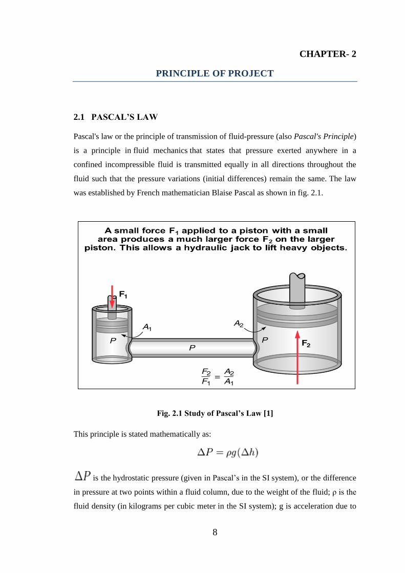
Pascal's law or the principle of transmission of fluid-pressure (also Pascal's Principle)
is a principle in fluid mechanics that states that pressure exerted anywhere in a
confined incompressible fluid is transmitted equally in all directions throughout the
fluid such that the pressure variations (initial differences) remain the same. The law
was established by French mathematician Blaise Pascal as shown in fig. 2.1.
Fig. 2.1 Study of Pascal’s Law [1]
This principle is stated mathematically as:
is the hydrostatic pressure (given in Pascal’s in the SI system), or the difference
in pressure at two points within a fluid column, due to the weight of the fluid; ρ is the
fluid density (in kilograms per cubic meter in the SI system); g is acceleration due to
9
gravity (normally using the sea level acceleration due to Earth's gravity, in SI
in metres per second squared);
is the height of fluid above the point of measurement, or the difference in
elevation between the two points within the fluid column (in metres in SI).
The intuitive explanation of this formula is that the change in pressure between two
elevations is due to the weight of the fluid between the elevations. A more correct
interpretation, though, is that the pressure change is caused by the change of potential
energy per unit volume of the liquid due to the existence of the gravitational field.
Note that the variation with height does not depend on any additional pressures.
Therefore, Pascal's law can be interpreted as saying that any change in pressure
applied at any given point of the fluid is transmitted undiminished throughout the
fluid.
2.2 PROJECT BASED ON PASCAL'S PRINCIPLE AND HYDRAULICS
Hydraulic systems use an incompressible fluid, such as oil or water, to transmit forces
from one location to another within the fluid. Most aircraft use hydraulics in the
braking systems and landing gear. Pneumatic systems use compressible fluid, such as
air, in their operation. Some aircraft utilize pneumatic systems for their brakes,
landing gear and movement of flaps.
A container, as shown below, contains a fluid. There is an increase in pressure as the
length of the column of liquid increases, due to the increased mass of the fluid above.
For example, in the figure below, P3 would be the highest value of the three pressure
readings, because it has the highest level of fluid above it .
If the above container had an increase in overall pressure, that same added pressure
would affect each of the gauges (and the liquid throughout) the same. For example P1,
P2, P3 were originally 1, 3, 5 units of pressure, and 5 units of pressure were added to
the system; the new readings would be 6, 8, and 10 as shown in fig. 2.2.
Applied to a more complex system below, such as a hydraulic car lift, Pascal's law

10
allows forces to be multiplied. The cylinder on the left shows a cross-section area of 1
square inch, while the cylinder on the right shows a cross-section area of 10 square
inches. The cylinder on
the left has a weight
(force) on 1 pound
acting downward on the
piston, which lowers
the fluid 10 inches. As
a result of this force,
the piston on the right
lifts a 10 pound weight
a distance of 1 inch.
The 1 pound load on the 1 square inch area causes an increase in pressure on the fluid
in the system. This pressure is distributed equally throughout and acts on every square
inch of the 10 square inch area of the large piston. As a result, the larger piston lifts up
a 10 pound weight. The larger the cross-section area of the second piston, the larger
the mechanical advantage, and the more weight it lifts as shown in fig. 2.3.
Fig. 2.3 Verification of Pascal’s law
The formulas that relate to this are shown below:
P1 = P2 (since the pressures are equal throughout).
Fig. 2.2 Pascal’s Principle
11
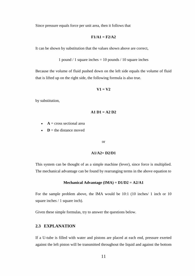
Since pressure equals force per unit area, then it follows that
F1/A1 = F2/A2
It can be shown by substitution that the values shown above are correct,
1 pound / 1 square inches = 10 pounds / 10 square inches
Because the volume of fluid pushed down on the left side equals the volume of fluid
that is lifted up on the right side, the following formula is also true.
V1 = V2
by substitution,
A1 D1 = A2 D2
A = cross sectional area
D = the distance moved
or
A1/A2= D2/D1
This system can be thought of as a simple machine (lever), since force is multiplied.
The mechanical advantage can be found by rearranging terms in the above equation to
Mechanical Advantage (IMA) = D1/D2 = A2/A1
For the sample problem above, the IMA would be 10:1 (10 inches/ 1 inch or 10
square inches / 1 square inch).
Given these simple formulas, try to answer the questions below.
2.3 EXPLANATION
If a U-tube is filled with water and pistons are placed at each end, pressure exerted
against the left piston will be transmitted throughout the liquid and against the bottom

12
of the right piston. (The pistons are simply "plugs" that can slide freely but snugly
inside the tube.) The pressure that the left piston exerts against the water will be
exactly equal to the pressure the water exerts against the right piston.
Suppose the tube on the right side is made wider and a piston of a larger area is used;
for example, the piston on the right has 50 times the area of the piston on the left. If a
1 N load is placed on the left piston, an additional pressure due to the weight of the
load is transmitted throughout the liquid and up against the larger piston. The
difference between force and pressure is important: the additional pressure is exerted
against the entire area of the larger piston. Since there is 50 times the area, 50 times as
much force is exerted on the larger piston. Thus, the larger piston will support a 50 N
load - fifty times the load on the smaller piston.
Forces can be multiplied using such a device. One Newton input produces 50 Newton
output. By further increasing the area of the larger piston (or reducing the area of the
smaller piston), forces can be multiplied, in principle, by any amount. Pascal's
principle underlies the operation of the hydraulic press. The hydraulic press does not
violate energy conservation, because a decrease in distance moved compensates for
the increase in force. When the small piston is moved downward 10 centimeters, the
large piston will be raised only one-fiftieth of this, or 0.2 centimeters. The input force
multiplied by the distance moved by the smaller piston is equal to the output force
multiplied by the distance moved by the larger piston; this is one more example of a
simple machine operating on the same principle as a mechanical lever.
2.4 APPLICATIONS OF PASCAL’S LAW
Pascal's principle applies to all fluids, whether gases or liquids. A typical application
of Pascal's principle for gases and liquids is the automobile lift seen in many service
stations (the hydraulic jack). Increased air pressure produced by an air compressor is
transmitted through the air to the surface of oil in an underground reservoir.
The oil, in turn, transmits the pressure to a piston, which lifts the automobile. The
relatively low pressure that exerts the lifting force against the piston is about the same
as the air pressure in automobile tires. Hydraulics is employed by modern devices

13
ranging from very small to enormous. For example, there are hydraulic pistons in
almost all construction machines where heavy loads are involved.
2.5 LINE DIAGRAM OF UNDERGROUND HYDRAULIC CAR PARKING
SYSTEM
We have designed an Underground Hydraulic Car Parking System which is shown as
shown in fig. 2.4 by simple line diagram. Our project is based on Pascal’s law where a
master cylinder is used which supply pressurized fluid to four pillar-cylinders with the
help of 4 ways connector. Pillar-cylinders lift the platform (platform with car to be
lifted) which is mounted on these Pillars-cylinders.
To apply pressure on the master cylinder’s fluid Rack and Pinion arrangement is used
which are coupled with a DC motor with the help of spindle. This spindle mounted on
two bearing and connects the DC motor and Pinion. DC motor run by DC supply
which was supply by Step down transformer after rectification. Here rectifier converts
the AC supply to DC supply and help to run DC motor. Two ways switch is provide
to rotate the switch in Clockwise and Anticlockwise direction.
Fig. 2.4 Line Diagram of UHCPS

14
2.6 CALCULATIONS
To design the Underground Hydraulic Car Parking System (UHCPS) first we have to
calculate the force required to drive the master cylinder’s piston or to pressurize the
fluid which further (pressurized fluid) supply to 4 pillar-cylinders and lift the platform
on which a car is parked.
Thus to calculate the Force required to life the 4 pillar-cylinders which are hydraulic
based, we will use here Pascal’s law. Here we have assumed following input
parameter to find the force required on master cylinder which further lift the pillar-
cylinders. All the input parameters are shown in table 2.1.
Table: 2.1 Following Input parameter required to determination of Force on
Master Cylinder:
S.No Description Parameters
1 Motor capacity 10 hp
2 Motor Rpm 1000rpm
3 Diameter of master cylinder (D) 0.15m
4 Cross-section area of master cylinder (A) 0.01766m2
5 Bore of pillar cylinder (d) 0.04m
6 Diameter of pinion (dp) 0.05m
7 Cross-section area of pillar cylinder (a) 0.001256m2
8 Equivalent area of pillar cylinder (ae) 4a (0.005024m2)
9 Load lifted by pillar cylinder (f) 22.563 KN
10 Radius of motor gear 0.05m
11 Stroke length of pillar cylinder 5m
Following parameter need to be calculated :
1 Stroke length of master cylinder L
2 Torque produced at pinion shaft Tps
15
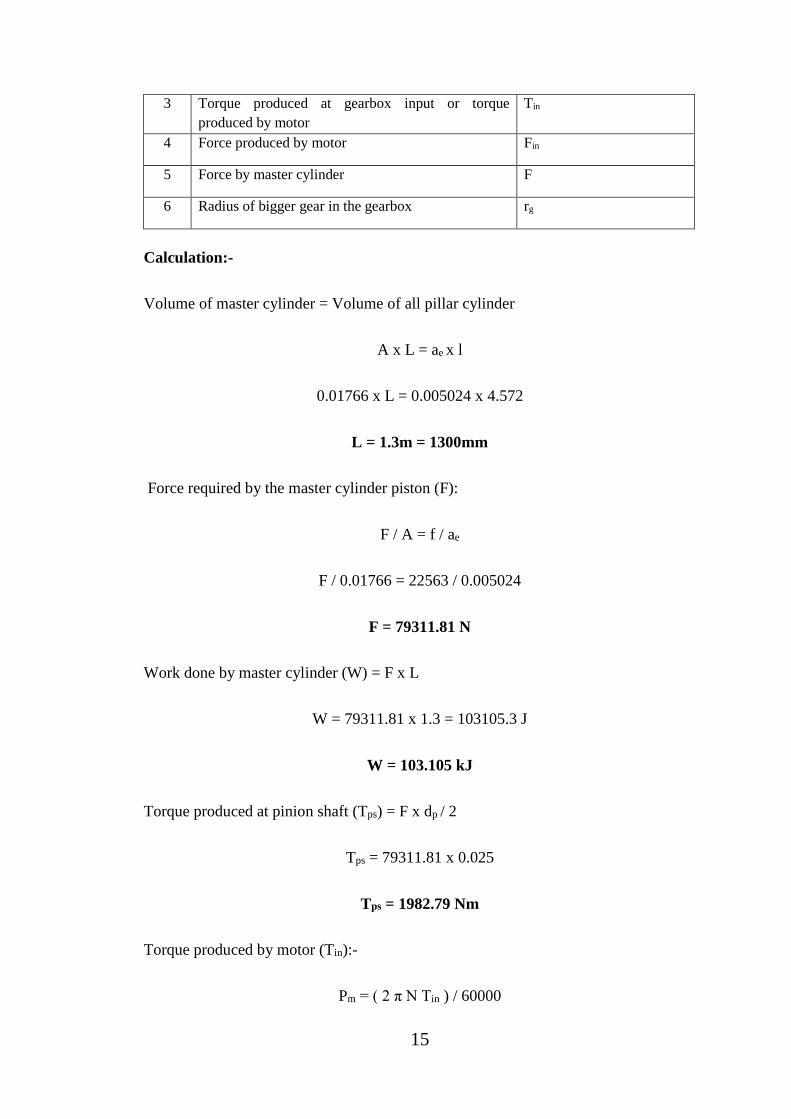
3 Torque produced at gearbox input or torque
produced by motor
Tin
4 Force produced by motor Fin
5 Force by master cylinder F
6 Radius of bigger gear in the gearbox rg
Calculation:-
Volume of master cylinder = Volume of all pillar cylinder
A x L = ae x l
0.01766 x L = 0.005024 x 4.572
L = 1.3m = 1300mm
Force required by the master cylinder piston (F):
F / A = f / ae
F / 0.01766 = 22563 / 0.005024
F = 79311.81 N
Work done by master cylinder (W) = F x L
W = 79311.81 x 1.3 = 103105.3 J
W = 103.105 kJ
Torque produced at pinion shaft (Tps) = F x dp / 2
Tps = 79311.81 x 0.025
Tps = 1982.79 Nm
Torque produced by motor (Tin):-
Pm = ( 2 π N Tin ) / 60000
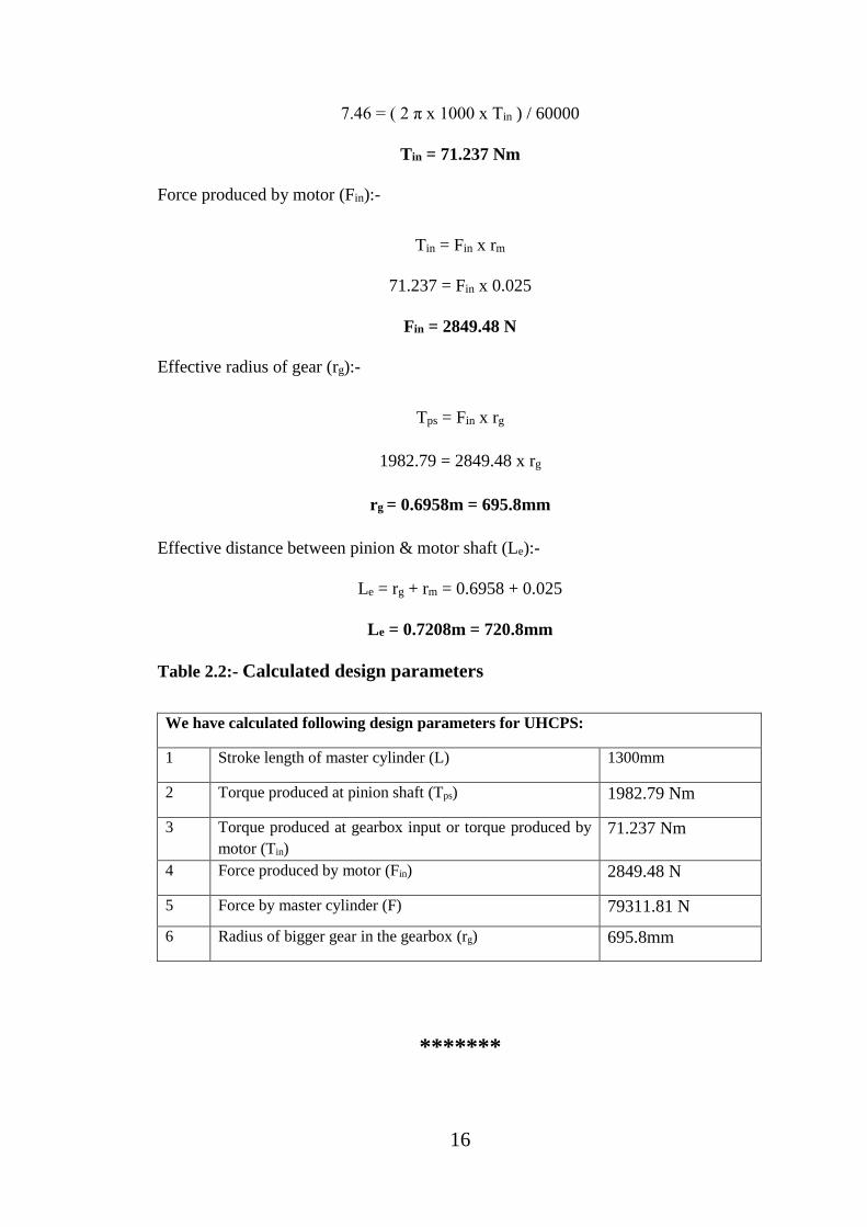
16
7.46 = ( 2 π x 1000 x Tin ) / 60000
Tin = 71.237 Nm
Force produced by motor (Fin):-
Tin = Fin x rm
71.237 = Fin x 0.025
Fin = 2849.48 N
Effective radius of gear (rg):-
Tps = Fin x rg
1982.79 = 2849.48 x rg
rg = 0.6958m = 695.8mm
Effective distance between pinion & motor shaft (Le):-
Le = rg + rm = 0.6958 + 0.025
Le = 0.7208m = 720.8mm
Table 2.2:- Calculated design parameters
We have calculated following design parameters for UHCPS:
1 Stroke length of master cylinder (L) 1300mm
2 Torque produced at pinion shaft (Tps) 1982.79 Nm
3 Torque produced at gearbox input or torque produced by
motor (Tin)
71.237 Nm
4 Force produced by motor (Fin) 2849.48 N
5 Force by master cylinder (F) 79311.81 N
6 Radius of bigger gear in the gearbox (rg) 695.8mm
*******

17
CHAPTER-3
COMPONENTS & MATERIAL SELECTION
In this chapter the Components or Hardware required to fabricate the Underground
Hydraulic Car Parking System (UHCPS) are given. This chapter also tabulated with
detailed information of components with their specification, quantity and cost.
3.1 COMPONENTS REQUIREMENT
1. Slow speed Crouzet motor gear box
2. Rack and pinion gear
3. Sliding channel
4. Bearing 608
5. Bearing stand
6. Syringe
7. Syringe pipe
8. Sliding switch
9. Transformer
10. Metal and wooden body frame
11. Cut off switch
12. T-junction
13. Diodes
14. Glue Gun
15. Nuts and Bolts

18
Table 3.1 Component Requirement with Specification & Quantity
S. No. Component Specification (mm) Quantity
1 Rack 100x20x20 1
2 Pinion Φ45, 22 teeth 1
3 DC motor 12V/90mA 1
4 Gear Box 1000rpm-4rpm 1
5 Sliding channel 210x40x13 1
6 Bearing 608 Φ8, Φ22,7 1
7 Bearing Stand Φ22, Φ30 1
8 Syringe 10ml 4
9 Master Cylinder Syringe 50ml 1
10 Syringe Pipe Φ6 1
11 Sliding Switch 24V/100mA 1
12 Cut off Switch 24V/100mA 2
13 Transformer 220V/110V – 12V/90mA 1
14 T – Junction 5 pin junction 1
15 Wooden Block 480x325x225 1
(a) Wooden Ply 1 5mm thickness 1
(b) Wooden Ply 2 11mm thickness 1
16 Parking Box 190x120x70 1
17 Diode 24V/100mA 4
18 Glue Gun 500ml 1
19 Nut and Bolt (Fasteners) 70mm 4
3.2 COMPONENT DETAILS
3.2.1 SLOW SPEED CROUZET MOTOR GEAR BOX
The Crouzet DC mind Brushless motors represent a new generation of direct current
brushless motors. They offer outstanding performance, more power, more precision
and more functionality. With a mechanical power rating of up to 150 W, the DC mind

19
Brushless motor is the most powerful in its range, yet is the same size as the old 80 W
version. So DC mind Brushless motors are suitable for the most demanding markets,
in industry, valves and pumps, access control and the energy sector.
12VDC 4RPM CROUZET MOTOR W/GEARBOX
Powerful gear motor.10 RPM @ 12
Vdc / 90 mA (no-load). Operates on
4-15 Vdc. 3.6" x 2.36" x 2.24"
overall dimensions. Crouzet motor
and final drive shaft both extend
from same side of plastic gearbox.
5/16" diameter flatted shaft is 0.9"
long. 8" pigtail leads as shown in
fig. 3.1.
The modern DC motor was invented by accident in 1873, when Zénobe Gramm
connected a spinning dynamo to a second similar unit, driving it as a motor. The
classic DC motor has a rotating armature in the form of an electromagnet. A rotary
switch called a commutator reverses the direction of the electric current twice every
cycle, to flow through the armature so that the poles of the electromagnet push and
pull against the permanent magnets on the outside of the motor. As the poles of the
armature electromagnet pass the poles of the permanent magnets, the commutator
reverses the polarity of the armature electromagnet. During that instant of switching
polarity, inertia keeps the classical motor going in the proper direction. (See the
diagrams 3.1a , 3.1b).
Fig. 3.1b Rotation of Armature
w.r.t. Stator [1]
Fig. 3.1c Rotation of Armature
w.r.t. Stator [1]
Fig. 3.1a DC Motor

20
In a simple DC electric motor, When the coil is powered, a magnetic field is
generated around the armature. The left side of the armature is pushed away from the
left magnet and drawn toward the right, causing rotation.
The armature continues to rotate. When the armature becomes horizontally aligned,
the commutator reverses the direction of current through the coil, reversing the
magnetic field. The process then repeats.
3.2.2 RACK AND PINION
Rack and pinion is a type of linear
actuator that comprises a pair of gears
which convert rotational motion into
linear motion. A circular gear called
"the pinion" engages teeth on a linear
"gear" bar called "the rack"; rotational
motion applied to the pinion causes the
rack to move, thereby translating the
rotational motion of the pinion into the
linear motion of the rack as shown in
fig. 3.2. For example, in a rack railway,
the rotation of a pinion mounted on a locomotive or a railcar engages a rack between
the rails and pulls a train along a steep slope.
3.2.3 SLIDING CHANNEL
Sliding channel gives the both forward and backward moment to the rack as shown in
fig. 3.3.
Fig. 3.3 Sliding Channel
Fig. 3.2 Rotation of a Pinion in a Rack
Railway [2]

21
3.2.4 BEARING (608)
Have you ever wondered how things like inline skate wheels and electric motors spin
so smoothly and quietly? The answer can be found in a neat little machine called a
bearing. The bearing makes many of the machines we use every day possible.
Without bearings, we would be constantly replacing parts that wore out from friction.
In this article, we'll learn how bearings work, look at some different kinds of bearings
and explain their common uses, and explore some other interesting uses of bearings
show as shown in fig. 3.4 and 3.5.
The concept behind a bearing is very simple: things roll better than they slide. The
wheels on your car are like big bearings. If you had something like skis instead of
wheels, your car would be a lot more difficult to push down the road.
That is because when things slide, the friction between them causes a force that tends
to slow them down. But if the two surfaces can roll over each other, the friction is
greatly reduced.
Bearings reduce friction by providing smooth metal balls or rollers, and a smooth
inner and outer metal surface for the balls to roll against. These balls or rollers "bear"
the load, allowing the device to spin smoothly.
The bearing above is like the one in a barstool. It is loaded purely in thrust, and the
entire load comes from the weight of the person sitting on the stool.
Fig. 3.4 Bearing 608 [5]
Fig. 3.5 Tapered Roller Bearing
from a Manual Transmission [5]

22
The bearing below is like the one in the hub of your car wheel. This bearing has to
support both a radial load and a thrust load. The radial load comes from the weight of
the car, the thrust load comes from the cornering forces when you go around a turn.
3.2.4.1 Ball Bearing
Ball bearings, as shown as shown in fig. 3.6, are probably the most common type of
bearing. They are found in everything from inline skates to hard drives. These
bearings can handle both radial and thrust loads, and are usually found in applications
where the load is relatively small.
In a ball bearing, the load is transmitted from the outer race to the ball, and from the
ball to the inner race. Since the ball is a sphere, it only contacts the inner and outer
race at a very small point, which helps it spin very smoothly. But it also means that
there is not very much contact area holding that load, so if the bearing is overloaded,
the balls can deform or squish, ruining the bearing.
3.2.5. BEARING STAND
The function of bearing stand is to support the bearing. We will fit the ball bearing
inside the hexagonal bolt as shown in fig. 3.7.
3.2.6. SYRINGE
A syringe is a simple pump consisting of a plunger that fits tightly in a tube as shown
in fig. 3.8 and 3.9. The plunger can be pulled and pushed along inside a cylindrical
Fig. 3.6 Sectional View of Ball Bearing [5]
Fig. 3.7 hexagonal Nut

23
tube (called a barrel), allowing the syringe to take in and expel a liquid or gas through
an orifice at the open end of the tube. The open end of the syringe may be fitted with
a hypodermic needle, a nozzle, or tubing to help direct the flow into and out of the
barrel. Syringes are often used to administer injections, insert intravenous drugs into
the bloodstream, apply compounds such as glue or lubricant, and measure liquids.
3.2.7. PIPE
A 6 mm diameter pipe is used for flow fluid.
Pipe is used for the conveyance of drinking
water, waste water, chemicals, heating fluid
and cooling fluids, foodstuffs, ultra-pure
liquids, slurries, gases, compressed
air and vacuum system applications as shown
in fig. 3.10.
3.2.8. SLIDING SWITCH
Slide switches as shown in fig. 3.11 are
mechanical switches using a slider that moves
(slides) from the open (off) position to the closed
(on) position. They allow control over current
flow in a circuit without having to manually cut or
splice wire. This type of switch is best used for
controlling current flow in small projects.
There are two common internal designs of slide
switches. The most common design uses metal
Fig. 3.8 Syringe of 10mL [5] Fig.3.9 Syringe of 60mL [5]
Fig.3.10 Pipe [1]
Fig. 3.11 Sliding Switch [1]

24
slides that make contact with the flat metal parts on the switch. As the slider is moved
it causes the metal slide contacts to slide from one set of metal contacts to the other,
actuating the switch. The second design uses a metal seesaw. The slider has a
spring that pushes down on one side of the metal seesaw or the other. Slide switches
are maintained-contact switches. Maintained-contact switches stay in one state until
actuated into a new state and then remain in that state until acted upon once again.
3.2.9. TRANSFORMER
As a step-down unit, the transformer
converts high-voltage, low-current power
into low-voltage, high-current power as
shown in fig. 3.12. The larger-gauge wire
used in the secondary winding is necessary
due to the increase in current. The primary
winding, which doesn’t have to conduct as
much current, may be made of smaller-
gauge wire.
3.2.10. METAL AND WOODEN BODY FRAME
Body-on-frame is an automobile construction
method mounting a separate body to a rigid
frame that supports the drive train was the
original method of building automobiles, and
continues to this day. Originally frames were
made of wood show as shown in fig. 3.13.
3.2.11. CUT OFF SWITCH
When used as an AC signal amplifier, the transistors Base biasing voltage is applied
in such a way that it always operates within its “active” region, that is the linear part
of the output characteristics curves are used as shown in fig. 3.14. However, both the
Fig.3.13 Wooden block
Fig. 3.12 Step down transformer

25
NPN & PNP type bipolar transistors can be made
to operate as “ON/OFF” type solid state switch
by biasing the transistors base differently to that
of a signal amplifier.
3.2.12. T-JUNCTION
Pipe networks are mainly used for transportation
and supply of fluids and gases. These networks vary from fewer pipes to thousands of
pipes (e.g. water supply network of a large city, see in figure 3.15). In addition to
pipes, the network also consists of elbows, T-junctions, bends, contractions,
expansions, valves, meters, pumps, turbines and many other components.
3.2.13. DIODE
In electronics, a diode is a two-terminal electronic component that conducts primarily
in one direction (asymmetric conductance); it has low (ideally zero) resistance to the
flow of current in one direction, and high (ideally infinite) resistance in the other.
A semiconductor diode, the most common type today, is a crystalline piece
of semiconductor material with a p–n junction connected to two electrical terminals as
shown in fig. 3.16.
3.2.14. GLUE GUN
Hot melt adhesive (HMA), also known as hot glue, is a form
of thermoplastic adhesive that is commonly supplied in solid cylindrical sticks of
Fig. 3.14 Cut off switch [5]
Fig.3.15 T-Junction [1]
Fig. 3.16 Diode [1]

26
various diameters, designed to be melted in an electric hot glue gun. The gun uses a
continuous-duty heating element to melt the plastic glue, which the user pushes
through the gun either with a mechanical trigger mechanism on the gun, or with direct
finger pressure. The glue squeezed out of the heated nozzle is initially hot enough to
burn and even blister skin. The glue is tacky when hot, and solidifies in a few seconds
to one minute. Hot melt adhesives can also be applied by dipping or spraying.
3.2.15. NUT AND BOLT
A nut is a type of fastener with a threaded hole. Nuts are almost always used opposite
a mating bolt to fasten a stack of parts together. The two partners are kept together by
a combination of their threads' friction, a slight stretch of the bolt, and compression of
the parts as shown in fig. 3.18.
3.3 COST OF COMPONENTS
We have purchase/procure the following component from market which cost is given
in the table 3.2.
Fig. 3.17 Nut and Bolt [2]
27
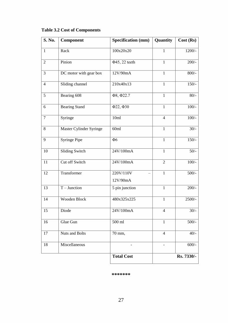
Table 3.2 Cost of Components
S. No. Component Specification (mm) Quantity Cost (Rs)
1 Rack 100x20x20 1 1200/-
2 Pinion Φ45, 22 teeth 1 200/-
3 DC motor with gear box 12V/90mA 1 800/-
4 Sliding channel 210x40x13 1 150/-
5 Bearing 608 Φ8, Φ22.7 1 80/-
6 Bearing Stand Φ22, Φ30 1 100/-
7 Syringe 10ml 4 100/-
8 Master Cylinder Syringe 60ml 1 30/-
9 Syringe Pipe Φ6 1 150/-
10 Sliding Switch 24V/100mA 1 50/-
11 Cut off Switch 24V/100mA 2 100/-
12 Transformer 220V/110V –
12V/90mA
1 500/-
13 T – Junction 5 pin junction 1 200/-
14 Wooden Block 480x325x225 1 2500/-
15 Diode 24V/100mA 4 30/-
16 Glue Gun 500 ml 1 500/-
17 Nuts and Bolts 70 mm, 4 40/-
18 Miscellaneous - - 600/-
Total Cost Rs. 7330/-
*******

28
CHAPTER-4
PROJECT CONSTRUCTION
In this chapter we have explained the fabrication or assembly process step by step
with their proper figures. These chapters also include the distribution of power supply
to efficiently run the project. This chapter has been included prior to fabrication
process of Underground Hydraulic Car Parking System (UHCPS) to make the
fabrication and assembly process easy.
4.1 METHODOLOGIES & CONSTRUCTION
Step-1
Now we take four 10 ml plastic syringe as hydraulic cylinder as shown in fig. 4.1.
Fig. 4.1 Plastic Syringe 60mL
Step-2
We take one more syringe and filled it with water/oil and now we connected both
syringe with plastic tube as shown in fig. 4.2.
If we pressurized one syringe second syringe lift up according to Pascal law, same
phenomena work with other syringe too.

29
Fig. 4.2 Transfer of Pressure through Fluid
4.2 ABOUT OUR PROJECT
Now we plan to construct this Pascal law concept as a final project. We use two
syringes and coupled with one sliding mechanism and this mechanism is power by
slow dc gear motor for Lifting good and vehicles.
4.3 PROJECT CONSTRUCTION STEPS
Step-1
First we arrange one sliding channel and fix it on wooden frame as shown in fig. 4.3.
Fig. 4.3 Sliding Channel Arrangement

30
Step-2:-
Sliding channel fixed on the wooden block by nails as shown in fig. 4.4.
Fig. 4.4 Fixing Sliding Channel on Wooden Base
Step-3
We use 8mm iron rod and cross on between 2 bearing stand. Then we fix one Pinion
gear in between 2 bearing stand. This pinion gear roll over rack mechanism which is
fixed on sliding channel as shown in fig. 4.5.
Fig. 4.5 Fixing Pinion Gear
Step-4:-
We attach one dc gear motor with rod shaft gear for sliding movement for entire set as
shown in fig. 4.6. Two way switch for dc motor clockwise / anticlockwise rotation.

31
Fig. 4.6 Attachment of DC Gear Motor with Rod Shaft Gear
Step-5:-
Attachment of master cylinder to the sliding channel for providing smooth and
constant fluid pressure to the master cylinder fluid as shown in fig. 4.7.
Fig. 4.7 Sliding Mechanism
Step-6
Now we construct a simple car lifting platform with help of 4 syringes and connect
with master syringe as shown in fig. 4.8.
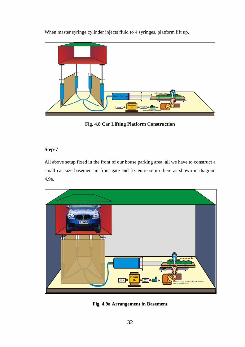
32
When master syringe cylinder injects fluid to 4 syringes, platform lift up.
Fig. 4.8 Car Lifting Platform Construction
Step-7
All above setup fixed in the front of our house parking area, all we have to construct a
small car size basement in front gate and fix entre setup there as shown in diagram
4.9a.
Fig. 4.9a Arrangement in Basement

33
We can park two cars at the time in one parking area with full safety as shown in fig.
4.9b.
Fig. 4.9b Arrangement in Basement
4.4 FUTURE LAYOUT
Commercial application of project in future which is shown in fig. 4.10a & 4.10b &
the figure 4.10c.
Fig. 4.10a Commercial Application of Project

34
Fig. 4.10b Commercial Application of Project
Fig. 4.10c Commercial Application of Project
4.5 POWER SUPPLY
A power supply is an electronic device that supplies electric energy to an electrical
load. The primary function of a power supply is to convert one form of electrical

35
energy to another and, as a result, power supplies are sometimes referred to as electric
power converters. Some power supplies are discrete, stand-alone devices, whereas
others are built into larger devices along with their loads. Examples of the latter
include power supplies found in desktop computers and consumer electronics devices.
4.5.1 AC-To-DC Supply
Some DC power supplies use AC mains electricity as an energy source. Such power
supplies will sometimes employ a transformer to convert the input voltage to a higher
or lower AC voltage. A rectifier is used to convert the transformer output voltage to a
varying DC voltage, which in turn is passed through an electronic filter to convert it to
an unregulated DC voltage. The filter removes most, but not all of the AC voltage
variations; the remaining voltage variations are known as ripple show as shown in fig.
4.11.
Fig. 4.11 Schematic of basic AC-to-DC power supply [1]
4.6 THEORY
4.6.1 Rectification
Rectification is a process of rendering an alternating current or voltage into a
unidirectional one. The component used for rectification is called ‘Rectifier’. A
rectifier permits current to flow only during the positive half cycles of the applied AC
voltage by eliminating the negative half cycles or alternations of the applied AC
voltage. Thus pulsating DC is obtained. To obtain smooth DC power, additional filter
circuits are required.

36
4.6.2 Full Wave Rectifier
A Full Wave Rectifier is a circuit,
which converts an ac voltage into a
pulsating dc voltage using both half
cycles of the applied ac voltage. It uses
two diodes of which one conducts
during one half cycle while the other
conducts during the other half cycle of
the applied. ac voltage.It is possible to
rectify both alternations of the input
voltage by using two diodes in the
circuit arrangement show as shown in
fig. 4.12.
When A is positive relative to C, the anode of D1 is positive with respect to its
cathode. Hence D1 will conduct but D2 will not. During the second alternation, B is
positive relative to C. The anode of D2 is therefore positive with respect to its
cathode, and D2 conducts while D1 is cut off.
There is conduction then by either D1 or D2 during the entire input-voltage cycle.
Since the two diodes have a common-cathode load resistor RL, the output voltage
across RL will result from the alternate conduction of D1 and D2. The output
waveform vout across RL, therefore has no gaps as in the case of the half-wave
rectifier.
The output of a full-wave rectifier is also pulsating direct current. In the diagram, the
two equal resistors R across the input voltage are necessary to provide a voltage
midpoint C for circuit connection and zero reference. Note that the load resistor RL is
connected from the cathodes to this centre reference point C.
Fig. 4.12 Full Wave Rectifier [1]

37
An interesting fact about the output waveform vout is that its peak amplitude is not 9
V as in the case of the half-wave rectifier using the same power source, but is less
than 4½ V. The reason, of course, is that the peak positive voltage of A relative to C is
4½ V, not 9 V, and part of the 4½ V is lost across R.
Though the full wave rectifier fills in the conduction gaps, it delivers less than half the
peak output voltage that results from half-wave rectification.
4.6.3 Bridge Rectifier
A bridge rectifier is an arrangement of four or more diodes in a bridge circuit
configuration which provides the same output polarity for either input polarity. It is
used for converting an alternating current (AC) input into a direct current (DC) output
as shown in fig. 4.13.
A more widely used full-wave rectifier circuit is the bridge rectifier. It requires four
diodes instead of two, but avoids the need for a centre-tapped transformer. During the
positive half-cycle of the secondary voltage, diodes D2 and D4 are conducting and
diodes D1 and D3 are non-conducting. Therefore, current flows through the
secondary winding, diode D2, load resistor RL and diode D4. During negative half-
cycles of the secondary voltage, diodes D1 and D3 conduct, and the diodes D2 and
D4 do not conduct. The current therefore flows through the secondary winding, diode
D1, load resistor RL and diode D3.
Fig. 4.13 Bridge Rectifier [1]
*******

38
CHAPTER-5
FABRICATION OF THE PROJECT
In this chapter we have executed the process of fabrication in proper way then all
these components assemble together as per planning and actual model of UHCPS
finally prepared. All these fabrication & assembly process given step by step in this
chapter.
There are following steps are followed for modelling the project:-
Step 1:-
We have prepared the wooden box whose dimension of upper panel 480x320x5 mm3
& lower panel 480x320x10 mm3, two side panel dimensions is 225x320x10 & the
dimension of back panel 480x225x10 in mm3 with open at one side as shown in fig.
5.1.
Fig. 5.1 Making Wooden Block
Step 2:-
Make a platform for car parking of dimension of upper and lower panel 190x120x5
and the dimension of two side panel 190x60x10 mm3 as shown in fig. 5.2.

39
Step 3:-
Making arrangements for up & down movement of car platform by using 4-syringes
of 10ml with the help of Glue Gun, which act as a hydraulic-lifting device & lift the
platform as shown in fig.5.3.
Step 4:-
With the help of water-tube of 6mm diameter we have connected the T-joint
connecter & 4- pillar cylinders (syringes). In this connecter there is one inlet passage
& 4 outlet passage. Inlet passage connected to master cylinder & outlet passage
connected to 4- pillar cylinders as shown in fig. 5.4.
Fig. 5.4 Fixing T-junction
Step 5:-
Fixing sliding channel 210x40x13 mm3 on wooden block by glue gun and after that
fix at the floor of the wooden box as shown in fig.5.5.
Fig. 5.2 Car Parking Platform
Fig. 5.3 Arrangements for Lifting
System
40
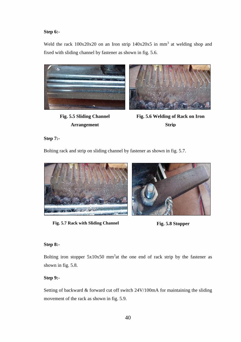
Step 6:-
Weld the rack 100x20x20 on an Iron strip 140x20x5 in mm3 at welding shop and
fixed with sliding channel by fastener as shown in fig. 5.6.
Step 7:-
Bolting rack and strip on sliding channel by fastener as shown in fig. 5.7.
Step 8:-
Bolting iron stopper 5x10x50 mm3at the one end of rack strip by the fastener as
shown in fig. 5.8.
Step 9:-
Setting of backward & forward cut off switch 24V/100mA for maintaining the sliding
movement of the rack as shown in fig. 5.9.
Fig. 5.5 Sliding Channel
Arrangement
Fig. 5.6 Welding of Rack on Iron
Strip
Fig. 5.8 Stopper Fig. 5.7 Rack with Sliding Channel

41
Fig. 5.9 Backward & Forward Cut off Switch
Step 10:-
Set up the Pinion (dia. 45, 22 teeth) on a shaft of dia. 8mm and connected to motor
and supported by bearing stand as shown in fig. 5.10
Step 11:-
Arranging of DC motor (12V/90mA) and Gearbox (1000rpm-4rpm) connected to
pinion arrangement for providing motion to rack and pinion as shown in fig. 5.11.
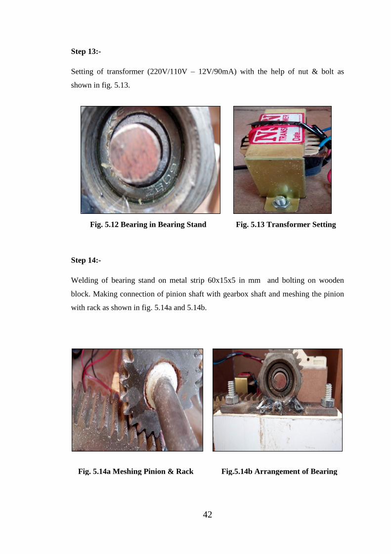
Step 12:-
Setting of bearing 608 in bearing stand which welded on the iron strip fixed by
fastener on the lower panel of wooden block as shown in fig.5.12.
Fig. 5.10 Pinion Arrangement
Fig. 5.11 Gearbox with DC Motor
42
Step 13:-
Setting of transformer (220V/110V – 12V/90mA) with the help of nut & bolt as
shown in fig. 5.13.
Step 14:-
Welding of bearing stand on metal strip 60x15x5 in mm and bolting on wooden
block. Making connection of pinion shaft with gearbox shaft and meshing the pinion
with rack as shown in fig. 5.14a and 5.14b.
Fig. 5.12 Bearing in Bearing Stand
Fig. 5.13 Transformer Setting
Fig. 5.14a Meshing Pinion & Rack
Fig.5.14b Arrangement of Bearing
Stand

43
Step 15:-
Connecting master cylinder (syringe) piston rod with sliding channel and fixing
master syringe (60ml) at the box floor with glue gun as shown in fig. 5.15a and
5.15b.
Step 16:-
Arranging two way sliding switch (24V/100mA) at the side of the wooden box by two
nails and connected to power supply for cut-off as shown in fig. 5.16.
Fig. 5.16 Two Way Sliding Switch
Step 17:-
Making bridge rectifier with the help of 4-diodes (24V/100mA) and making wire
connections with different electrical components and also providing input connection
for the system as shown in fig. 5.17a and 5.17b.
Fig. 5.15a Connection of
Sliding Channel
Fig. 5.15b Master Syringe
Arrangement

44
Fig. 5.17a Rectifier & Wire Connections
Fig. 5.17b Input Wire Connection
Step 18:-
Complete layout of the UHCPS throughout assembling of all component as a whole
which is as shown in fig. 5.18a, 5.18b and 5.18c.
Fig. 5.18a Final View of the Project

45
Fig. 5.18b Final View of the Project
Fig. 5.18c Final View of the Project

46
5.1 COST OF COMPONENTS
Prior to fabrication of Underground Hydraulic Car Parking System (UHCPS) we have
required the following components with their quantity and
Table 5.1 Total Cost of UHCPS
S. No. Component Cost (Rs)
1 Component Cost 6730/-
2 Project Manufacturing cost 1500/-
3 Miscellaneous 600/-
Total cost 8830/-
Table 5.2 Tentative Cost of Actual UHCPS
S.
No.
Component Material/Specification Quantity Cost(Rs)
1 Motor 10Hp / 1000rpm 1 13000/-
2 Rack C45, Carbon steel 1 2000/-
3 Pinion Steel/Spur gear 1 250/-
4 Gearbox Cycloidical 1 7000/-
5 Master cylinder Carbon steel, Stainless
steel
1 1800/-
6 Pillar cylinder Carbon steel, Stainless
steel
4 1200/-
7 Sliding channel Cold rolled steel 1 7000/-
8 Pressure pipe Synthetic rubber 1 1300/-
9 Frame Mild steel 3 33000/-
10 Building Material Bricks, Concrete, Sand,
Cement, bar
------- 30500/-
11 Labour Cost ------- ------- 10000/-
12 Miscellaneous cost ------- ------- 10000/-
Total Estimated Cost 117050/-
*******
47
6. CONCLUSION
1. An underground car parking system is a mechanical device that multiplies
parking capacity inside a parking lot.
2. This innovative, space-saving car lift & storage system doubles our parking space
by putting your car underground.
3. We have got limited square footage or simply prefer to store our vehicle safely;
our project is electro-hydraulic mechanism lowers or lifts our vehicle with the
touch of a button.
4. Multi- storey car park systems are less expensive per parking slot, since they tend
to require less building volume and less ground area than a conventional facility
with the same capacity.
5. By the use of this project, we provide multiple cars parking facility in less space
which will be very helpful in resolving the problems of urban areas over car
parking.
6. There are several advantages of employing a car park system for urban planners,
business owners and vehicle drivers. They offer convenience for vehicle users and
efficient usage of space for urban-based companies.
7. Finally an underground car parking system is a way to parking a car or multiple
cars in a limited space. It also provides security and safety of cars in low cost of
parking.
*******

48
7. SUGGESTION FOR FUTURE WORK
1. In future, increase the level of parking slot for parking more than two cars (three
or four) at a place.
2. Use facilitates multiple stoppers for multi-level parking by providing Relays in the
electronic circuit.
3. In future, sliding channel and rack can be replaced by mechanical pump such as
gear pump which also reduces the floor space.
4. In future, in place of rack & pinion and sliding channel, rope & rollers can be used
for pushing and pulling the piston of master cylinder for reducing the space.
5. Pillar cylinders can be set at the side corners of the parking lot instead of down
corners of parking lot for reducing the depth of parking lot or basement.
6. Sensors can be used for lift up & down process, in future.
*******

49
8. REFERENCES
1. https://en.wikipedia.org/wiki/Car_parking_system
2. http://www.alibaba.com/
3. https://www.youtube.com/watch?v=8xNxwZnMPaQ
4. A textbook of Bansal R.K., Fluid Mechanics And Hydraulic Machines, Laxmi
Publications (P) Ltd , Ninth edition, 2010
5. http://scienceplx.com/
6. https://www.techtransfer.com/
*******

50
9. APPENDIX
1. Hydraulic Drive System: A hydraulic drive system is a drive or
transmission system that uses pressurized hydraulic fluid to power hydraulic
machinery. The term hydrostatic refers to the transfer of energy from flow and
pressure, not from the kinetic energy of the flow.
2. Pascal’s Law: Pascal's law or the principle of transmission of fluid-
pressure (also Pascal's Principle) is a principle in fluid mechanics that states that
pressure exerted anywhere in a confined incompressible fluid is transmitted
equally in all directions throughout the fluid such that the pressure variations
(initial differences) remain the same.
3. Slow Speed Crouzet Motor Gear Box: The Crouzet DC mind Brushless motors
represent a new generation of direct current brushless motors.
4. Rack And Pinion: Rack and pinion is a type of linear actuator that comprises a
pair of gears which convert rotational motion into linear motion.
5. Bearing 608: Bearings reduce friction by providing smooth metal balls or rollers,
and a smooth inner and outer metal surface for the balls to roll against. These balls
or rollers "bear" the load, allowing the device to spin smoothly. (608 means = ball
bearing with 8mm internal dia. & 22mm external dia.)
6. Syringe: A syringe is a simple pump consisting of a plunger that fits tightly in a
tube. The plunger can be pulled and pushed along inside a cylindrical tube (called
a barrel), allowing the syringe to take in and expel a liquid or gas through
an orifice at the open end of the tube.
7. Sliding Switch: Slide switches are mechanical switches using a slider that moves
(slides) from the open (off) position to the closed (on) position. They allow
control over current flow in a circuit without having to manually cut or splice
wire.
8. Transformer: As a step-down unit, the transformer converts high-voltage, low-
current power into low-voltage, high-current power.
9. Diode: In electronics, a diode is a two-terminal electronic component that
conducts primarily in one direction (asymmetric conductance); it has low (ideally
zero) resistance to the flow of current in one direction, and high (ideally infinite)
resistance in the other.
51
10. Glue Gun: Hot melt adhesive (HMA), also known as hot glue, is a form
of thermoplastic adhesive that is commonly supplied in solid cylindrical sticks of
various diameters, designed to be melted in an electric hot glue gun.
11. Rectification: Rectification is a process of rendering an alternating current or
voltage into a unidirectional one. The component used for rectification is called
‘Rectifier’.
12. Bridge Rectifier: A bridge rectifier is an arrangement of four or more diodes in
a bridge circuit configuration which provides the same output polarity for either
input polarity. It is used for converting an alternating current (AC) input into a
direct current (DC) output.
*******
Related Documents