Subject to modifications | EN Technical information Installation instructions 4 214 045 / 00 - 07/15 Hoval products must be installed and commissioned only by appropriately qualified experts. These instruc- tions are intended exclusively for the specialist. Elec- trical installations may only be carried out by a qualified electrician. The floor standing oil condensing boiler UltraOil ® (320D- 600D) are designed and approved for use as heat gen- erators for hot water heating systems with a permissible flow temperature of up to 90 ºC 1) , in accordance with EN 483 and EN 677. They are designed for continuously adjustable reduced output operation in heating systems. 1) see section technical data UltraOil ® (320D,400D,500D,600D) Oil condensing double boiler These instructions apply to the following ty- pes: 41-UltraOil ® (320D) 118 - 320 kW 41-UltraOil ® (400D) 155 - 400 kW 41-UltraOil ® (500D) 188 - 500 kW 41-UltraOil ® (600D) 227 - 600 kW

Welcome message from author
This document is posted to help you gain knowledge. Please leave a comment to let me know what you think about it! Share it to your friends and learn new things together.
Transcript

Subject to modifi cations | EN
Technical informationInstallation instructions
4 214 045 / 00 - 07/15
Hoval products must be installed and commissioned only by appropriately qualified experts. These instruc-tions are intended exclusively for the specialist. Elec-trical installations may only be carried out by a qualified electrician.
The floor standing oil condensing boiler UltraOil® (320D-600D) are designed and approved for use as heat gen-erators for hot water heating systems with a permissible flow temperature of up to 90 ºC1), in accordance with EN 483 and EN 677. They are designed for continuously adjustable reduced output operation in heating systems.1) see section technical data
UltraOil® (320D,400D,500D,600D)Oil condensing double boiler
These instructions apply to the following ty-pes:41-UltraOil® (320D) 118 - 320 kW41-UltraOil® (400D) 155 - 400 kW41-UltraOil® (500D) 188 - 500 kW41-UltraOil® (600D) 227 - 600 kW

1. Safety instructions1.1 Key to symbols used ...........................................................................................................................................................3
2. Assembly2.1 Procedure way .....................................................................................................................................................................3
3. Technical Information3.1 Dimensions ..........................................................................................................................................................................43.2 Space requirements ............................................................................................................................................................53.3 Technische Daten UltraOil® (320D-600D) ............................................................................................................................6
4. Installation4.3 Flue gas line dimensions (overpressure) ...........................................................................................................................84.4 Flue gas line dimensions (negative pressure) ...................................................................................................................84.5 Hydraulic connection ..........................................................................................................................................................94.6 Boiler sequential switching circuit / Electrical connections / Parameters .......................................................................94.6.1 Schematic coordination .....................................................................................................................................................94.6.2 System KAE010 ..............................................................................................................................................................104.6.3 TTE-WEZ (1) ..................................................................................................................................................................134.6.4 TTE-WEZ (2) ..................................................................................................................................................................144.6.5 System KAE020 ..............................................................................................................................................................154.6.6 TTE-WEZ (1) ..................................................................................................................................................................184.6.7 TTE-WEZ (2) ..................................................................................................................................................................194.6.8 Legende..........................................................................................................................................................................20
2 4 214 045 / 00
TABLE OF CONTENTS

Dear CustomerThese instructions concerning our oil condensing boilers UltraOil® (320D-600D) represent additional information on the construction and commissioning of the twin boiler system.
Please see the attached instructions for basic information on technical details, commissioning, servicing and operating:
• Technical Information Installation inst-ructions
• Operating instructions
It is imperative for the boiler commissio-ning to be carried out by a Hoval service engineer or a trained Hoval partner.
1. Safety instructions
i Maximum overpressure in the common flue gas line 60 Pa
1.1 Key to symbols used
Tools:Shows the tools required for the following work.Instruction:Prompts you to carry out an action.Result:Shows the expected reaction to your action.
i Note:Provides important information.Safety information:Indicates an immediate hazard to persons.Warning information:Indicates danger to machines and installa-tions.
§ Reference to standards and regulations.
2. Assembly2.1 Procedure way
1. Prior to placing the boiler in position it must be ther-mally insulated and clad as far the plinth panels in accordance with the UltraOil® installation instructions.
2. The UltraOil® twin boilers are installed side by side according to the dimensional drawings below. (The hydraulic connection lines are optional).
2a. Mounting of the plinth panels and the optional con-densate box according to UltraOil® installation instruc-tions.
3. Seeseparateinstructionsforthemountingofthefluegas overpressure set!
4. Optional:Mounting of the hydraulic pipeline connection set (commonflowandreturn).
i See the instructions for the hydraulic connection set.
34 214 045 / 00
ASSEMBLY

3. Technical Information3.1 Dimensions
UltraOil® (320D-600D)(All dimensions in mm)
1 Flow/safetyflow DN65/ PN61a Flow pipe connection (option) DN80/ PN6
2 Low-temperature return DN65/ PN62a Low temperature-return pipe connection (option) DN80/ PN6
3 High temperature-return DN65/ PN63a High temperature-return pipe connection (option) DN80/ PN6
4 Flue gas outlet (320D, 400D) Ø305/ 3154 Flue gas outlet (500D, 600D) Ø351/ 3555 Condensate drain/syphon DN256 Control panel7 Electrical connection right/left8 Assemblytubeflow(option)9 Assemblytubereturnflow(option)
10 Expansion Rp 1"11 Connection safety valve Rp 1 ¼"12 Maximum pressure limiter Rp ¾"13 Safety temperature limiter Rp ½"14 Motorised air shut-off valve
UltraOil® Typ A B C D E F G H I J K L M N O P Q R S
(320D) 2709 2200 252 770 610 680 1412 1492 1955 889 1907 844 106 1794 1009 2123 709 950 1305(400D) 2901 2408 236 767 800 690 1412 1492 1955 889 1907 844 106 1794 1009 2123 709 950 1305(500D, 600D) 3284 2708 398 982 888 690 1483 1600 2063 899 2015 899 51 1849 1064 2278 719 950 1449
4 4 214 045 / 00
TECHNICAL INFORMATION

3.2 Space requirements
UltraOil® (320D-600D)(All dimensions in mm)
UltraOil® Typ A B C
(320D) 2709 1492 1794(400D) 2901 1492 1794(500D, 600D) 3284 1600 1849
Detailed dimensions and dimensions for bringing insee individual boiler UltraOil® (160-300)
Dimensions neutralisation unit see individual boiler UltraOil® (160-300)
54 214 045 / 00
TECHNICAL INFORMATION
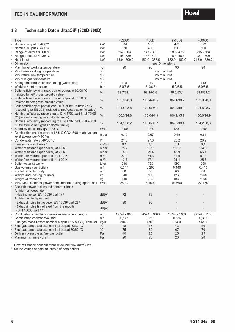
3.3 Technische Daten UltraOil® (320D-600D)
Type (320D) (400D) (500D) (600D)• Nominal output 80/60 °C kW 304 380 476 572• Nominal output 40/30 °C kW 320 400 500 600• Range of output 80/60 °C kW 114 - 303 147 - 380 180 - 476 215 - 568• Range of output 40/30 °C kW 119 - 320 155 - 400 189 - 500 227 - 600• Heat input kW 115,0 - 309,0 150,0 - 388,0 182,0 - 482,0 218,0 - 580,0• Dimension see Dimensions• Max. boiler working temperature °C 90 90 90 90• Min. boiler working temperature °C no min. limit• Min.returnflowtemperature °C no min. limit• Min.fluegastemperature °C no min. limit• Safety temperature limiter setting (water side) °C 110 110 110 110• Working / test pressure bar 5,0/6,5 5,0/6,5 5,0/6,5 5,0/6,5• Boilerefficiencywithmax.burneroutputat80/60°C(relatedtonet/grosscalorificvalue) % 98,7/93,1 98,2/92,6 99,0/93,4 98,8/93,2
• Boilerefficiencywithmax.burneroutputat40/30°C(relatedtonet/grosscalorificvalue) % 103,9/98,0 103,4/97,5 104,1/98,2 103,9/98,0
• Boilerefficiencyatpartialload30%atreturnflow27°C(accordingtoEN303)(relatedtonet/grosscalorificvalue) % 104,5/98,6 104,0/98,1 104,9/99,0 104,6/98,7
• Nominalefficiency(accordingtoDIN4702part8)at75/60°C(relatedtonet/grosscalorificvalue) % 100,5/94,8 100,0/94,3 100,9/95,2 100,6/94,9
• Nominalefficiency(accordingtoDIN4702part8)at40/30°C(relatedtonet/grosscalorificvalue) % 104,1/98,2 103,6/97,7 104,3/98,4 104,2/98,3
• Stand-bydeficiencyqBat70°C Watt 1000 1040 1200 1200• Combustion gas resistance,12,5 % CO2, 500 m above sea,
level (tolerance+/- 20 %) mbar 0,45 0,67 0,49 0,61
• Condensate rate at 40/30 °C l/h 21,6 27,0 20,2 20,2• Flow resistance boiler 1 z-Wert 0,1 0,1 0,1 0,1• Water resistance (per boiler) at 10 K mbar 75,2 117,6 183,7 264,5• Water resistance (per boiler) at 20 K mbar 18,8 29,4 45,9 66,1• Waterflowvolume(perboiler)at10K m3/h 27,4 34,3 42,9 51,4• Waterflowvolume(perboiler)at20K m3/h 13,7 17,1 21,4 25,7• Boiler water capacity Liter 680 720 590 580• Gas volume (per boiler) m3 0,347 0,290 0,440 0,440• Insulation boiler body mm 80 80 80 80• Weight (incl. casing, burner) kg 840 900 1268 1268• Weight of transport kg 740 780 1068 1068• Min./ Max. electrical power consumption (during operation) Watt 8/740 8/1000 8/1660 8/1660• Acoustic power incl. sound absorber hood
Ambient air dependent- Heating noise (EN 15036 part 1) 2 dB(A) 72 73 - -Ambient air independent- Exhaust noise in the pipe (EN 15036 part 2) 2 dB(A) 90 90 - -- Exhaust noise is radiated from the mouth (DIN 45635 part 47) dB(A) - - - -
• Combustion chamber dimensions Ø-inside x Length mm Ø524 x 800 Ø524 x 1000 Ø624 x 1100 Ø624 x 1100• Combustion chamber volume m3 0,173 0,216 0,336 0,336• Fluegasmassflowatnominaloutput12,5%CO2 Diesel oil kg/h 504,0 730,0 784,0 945,0• Flue gas temperature at nominal output 40/30 °C °C 48 58 43 50• Flue gas temperature at nominal output 80/60 °C °C 75 80 67 70• Deliverypressureatfluegasoutlet Pa 40 25 25 25• Maximum chimney draft Pa 20 20 20 20
1Flowresistanceboilerinmbar=volumeflow(m3/h)2 x z2 Sound values at nominal output of both boilers
6 4 214 045 / 00
TECHNICAL INFORMATION

4. Installation4.1 Boiler room requirements
Regardingthebuildingspecificationsforboilerroomsandtheir supply and extract air handling, the current building supervisoryofficeregulationsspecifictothestateorcountryare to be observed.
Ensure an adequate supply of fresh air to the boiler room tomakesurethatthereisanunobstructedflowofthe combustion air required for the operation of all com-bustion devices in the boiler room and so that there is no shortage of oxygen for operating personnel.The binding values for the size of intake air apertures are not usually stated in the relevant regulations, it is laid down only that the partial vacuum in the boiler room must not exceed 3 N/m2.
4.2 Flue gas connection and chimney
The fluegas systemmust begastight,wa-tertight, resistant to acids and approved for usewith thecorrespondingfluegastempe-ratures of up to 120°C and for overpressure.
Horizontal connection lines must be routed with a downward slope of at least 50 mm per running metre of their length in the direction of the boiler to ensure that condensate can flowunhinderedbacktotheboiler.Thewholefluegassystemmustbedesignedtopreventcondensate collecting.
The UltraOil®isdeliveredwithafluegassafetytempe-raturelimiter.Forthisreason,noadditionalfluegassa-fetytemperaturelimiterisrequiredforfluegassystemswithamax.permissiblefluegastemperatureof120°.
Asaresultofthewatervapourinthefluegasandthelowfluegastemperature,condensateformsinthechimney.This means that oil condensing boilers cannot be connec-ted to conventional domestic chimneys.Thevalidofficialstipulationsandregulationswithregardtofluegasevacuationmustbeobserved.
Therearetwopossiblewaystoevacuatefluegasfromoilcondensing boilers:
a) theuseofspecialfluegasconduitsapprovedbythebuilding authorities,
b) the use of moisture-resistant chimneys which are appro-vedforfluegastemperaturesofover40°C,connectedto the oil condensing boiler in the boiler installation room bymeansofapprovedfluegasconduits.
In both cases, the cross-sections and maximum lengths mustbecalculatedonthebasisofthefluegasmassflow,flue gas temperature and available maximum deliverypressureatthefluegasoutletinaccordancewiththetablein section 4.2 (EN 13384).
74 214 045 / 00
INSTALLATION

4.3 Flue gas line dimensions (overpressure)Principles
• Height above sea level max. 1000 m.
• The first 2 m of the flue gas line are to be executed in the same dimensions as the flue gas connectors.
• Combustion air: - In the case of room air-independent operation (ac-cessories optional) the air pipe must be at least the samedimensionasthefluegaspipe.
- Ifthefluegaslinediameterisgreaterthanthatofthecombustion air line, an individual calculation must be made.
• Flue gas overpressure set: - Compellingly necessary, included in the scope of de-livery!
Boiler Flue gas line (smooth walled) Number of bows 90° (flue gas + air supply)Type Flue gas dim. Designation Totalpipelenghtinm(fluegas+airsupply)
UltraOil® innen DN 1 2 3 4 5 *
(320D) 200 300 50 50 50 50(400D) 200 50 50 50 45(320D) 200 350 50 50 50 50(400D) 200 50 50 50 50(500D) 250 – – – –(600D) 250 40 40 38 35(600D) 250 400 50 50 50 50
Notice: The data contained in the table «Flue gas line dimensions» represent guide values. Anexactcalculationforthefluegasductmustbemadeon-site.
* With 5 bends or more the residual overpressure of the device is to be reduced by 30% for the calculation.
4.4 Flue gas line dimensions (negative pressure)
Thefluegassystemistobedimensionedinsuchawaythat no back circulation is possible in the room. A safe operationofthefluegassystemhastobeprovedbyap-proved measuring principles.
8 4 214 045 / 00
INSTALLATION

4.5 Hydraulic connection
• Ensure that the boilers are in each case connected in the Tichelmann system.
• Please comply with separate installation instructions if the optional hydraulic set is used.
• When using the high temperature-return, install this so that the connection socket is located on the same size (see chapter 3.1).
4.6 Boiler sequential switching circuit / Electri-cal connections / Parameters
4.6.1 Schematic coordination
System Oil boilerNumber of boilers
Main pumps Water heating
Heating circ-le assembly GLT option
UltraOil® 2 1 - ... MK0-10V module (temperature)
Water heater 1 - ... MK
KA100
KA090
94 214 045 / 00
INSTALLATION

4.6.2 System KAE010 Application without main pump Boiler sequential controller circuit double boiler by TTE
1
A
B
D
E
C
F
2 3 4 5 6 7 8 9
1 2 3 4 5 6 7 8 9
A
B
D
E
C
F
KAE010.dwg
Achtung ! Für die Installation muss das anlagenbezogene Schema verwendet werden!Attention! This is just a schematic. For installation please use the detail-plan!Attenzione! Per la messa in opera, utilizzare le schema dettagliato!Attention! Pour la réalisation pratique de l'installation, il faut utiliser le schéma détaillé!
Datum:
Datei:Version:
Blatt:
Hydr. Verbindungshinweise /Notice / Nota / Remarque:
1 4.1...
09.03.2015KAE010(BEDE010) Name:
Y10.1 Y10.2
TTE-WEZ
AF
RBM
TTE-GW
TTE-WEZ
P
HT
NT
UltraOil
P
HT
NT
UltraOil
YK1
MK1
T T
B1.1VF1
SF
T
SLP T
T
DKP
T T
MK2
T T
B1.2VF2
YK2
SB-Y4OFA200 TTE-GLT SB-Y4
OFA200
1
A
B
D
E
C
F
2 3 4 5 6 7 8 9
1 2 3 4 5 6 7 8 9
A
B
D
E
C
F
KAE010.dwg
Achtung ! Für die Installation muss das anlagenbezogene Schema verwendet werden!Attention! This is just a schematic. For installation please use the detail-plan!Attenzione! Per la messa in opera, utilizzare le schema dettagliato!Attention! Pour la réalisation pratique de l'installation, il faut utiliser le schéma détaillé!
Datum:
Datei:Version:
Blatt:
E1 Verbindungshinweise /Notice / Nota / Remarque:
2/8 4.1...
09.03.2015KAE010 Name:
10
SHNPEL
230V / 13ANetz/Power supply/
Rete/SecteurYK1
NM1~
SLP
M1~
MK1
TTE-WEZ
L- N- L N PES1
L PE NNetz-in VA1
NLSLP
N LDKP
N LVA2
N L1N
MK1N L
B1
PENetz-outN L1
12VE1
12AF
12SF
12VF1
12VE2/IMP
-VE10V
+ +- -H1
+ ABOT
BRS485
A
T
HCAN
L +
T CAN
1
R-CAN ADR.OnOff
4 3 2 1
GB
CA
N
1
Display/Affichage(Option/opzione)
VA10V/PWM
230V~max. 4AT
10ATTTE-BM
AN
B1.1
T
HL +
T
L H
T
(R)BM(max. 3)
BUS Verbindung zwischen den Regel-Modulen /BUS connection between the control modules /Liaison BUS entre les modules de régulation /Collegamento BUS tra i moduli di regolazione
BUS-CAN
AF SF VF1
Ultra
OilÒ
£ 8
0 kW
E13.
1 / E
13.2
L PE N
0 1
SH NPEL230V / 16ANetz/Power
supply/Rete/SecteurUltra
OilÒ
³11
0 kW
E13.
3
InternOFA200
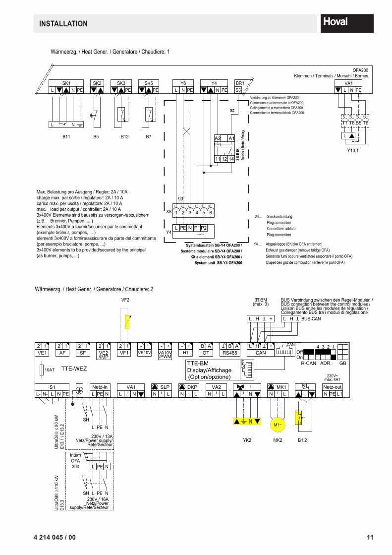
Wärmeerzg. / Heat Gener. / Generatore / Chaudiere: 1
M1~
DKP
10 4 214 045 / 00
INSTALLATION
1
A
B
D
E
C
F
2 3 4 5 6 7 8 9
1 2 3 4 5 6 7 8 9
A
B
D
E
C
F
KAE010.dwg
Achtung ! Für die Installation muss das anlagenbezogene Schema verwendet werden!Attention! This is just a schematic. For installation please use the detail-plan!Attenzione! Per la messa in opera, utilizzare le schema dettagliato!Attention! Pour la réalisation pratique de l'installation, il faut utiliser le schéma détaillé!
Datum:
Datei:Version:
Blatt:
E2 Verbindungshinweise /Notice / Nota / Remarque:
3/8 4.1...
09.03.2015KAE010 Name:
T
B12B5B11
NL
OFA200Klemmen / Terminals / Morsetti / Bornes
L N PESK1 SK2 SK3
PE
T
B7
SK5PE N PE
VA1L
T7 T8 B51 2 3
T64
L
Y10.1
Wärmeerzg. / Heat Gener. / Generatore / Chaudiere: 1
Max. Belastung pro Ausgang / Regler: 2A / 10Acharge max. par sortie / régulateur: 2A / 10 Acarico max. per uscita / regolatore: 2A / 10 Amax. load per output / controller: 2A / 10 A3x400V Elemente sind bauseits zu versorgen-/abzusichern(z.B. Brenner, Pumpen, ....)Eléments 3x400V à fournir/sécuriser par le commettant(exemple brûleur, pompes, ... )elementi 3x400V a fornire/assicurare da parte del committente(per esempio bruciatore, pompe, ...)3x400V elements to be provided/secured by the principal(as burner, pumps, ...)
N PEY4
N PEY6
LBR1S3
sz
Verbindung zu Klemmen OFA200Connexion aux bornes de la OFA200Collegamento a morsettiera OFA200Connection to terminal block OFA200
P1L
X81 2 3 4
1 2 3 45 6
5 6
A1A2
11 1412
230V
gg
X8... SteckverbindungPlug connectionConnettore cablatoPlug connection
Y4 ... Abgasklappe (Brücke OFA entfernen)Exhaust gas damper (remove bridge OFA)Serranda fumi oppure ventilatore (asportare il ponto OFA)Clapet des gaz de combustion (enlever le pont OFA)
SB-R
1KRe
lais
/ Re
lé /
Rela
y
P2NY4
Systembaustein SB-Y4 OFA200 /Système modulaire SB-Y4 OFA200 /
Kit a elementi SB-Y4 OFA200 /System unit SB-Y4 OFA200
PE
1
A
B
D
E
C
F
2 3 4 5 6 7 8 9
1 2 3 4 5 6 7 8 9
A
B
D
E
C
F
KAE010.dwg
Achtung ! Für die Installation muss das anlagenbezogene Schema verwendet werden!Attention! This is just a schematic. For installation please use the detail-plan!Attenzione! Per la messa in opera, utilizzare le schema dettagliato!Attention! Pour la réalisation pratique de l'installation, il faut utiliser le schéma détaillé!
Datum:
Datei:Version:
Blatt:
E2 Verbindungshinweise /Notice / Nota / Remarque:
4/8 4.1...
09.03.2015KAE010 Name:
TTE-WEZ
L- N- L N PES1
L PE NNetz-in VA1
NLSLP
N LDKP
N LVA2
N L1N
MK1N L
B1
PENetz-outN L1
12VE1
12AF
12SF
12VF1
12VE2/IMP
-VE10V
+ +- -H1
+ ABOT
BRS485
A
T
HCAN
L +
T CAN
1
R-CAN ADR.OnOff
4 3 2 1
GB
CA
N
1
Display/Affichage(Option/opzione)
VA10V/PWM
230V~max. 4AT
10ATTTE-BM
AN
HL +
T
L H
T
(R)BM(max. 3)
BUS Verbindung zwischen den Regel-Modulen /BUS connection between the control modules /Liaison BUS entre les modules de régulation /Collegamento BUS tra i moduli di regolazione
BUS-CAN
Wärmeerzg. / Heat Gener. / Generatore / Chaudiere: 2
10
SHNPEL
230V / 13ANetz/Power supply/
Rete/SecteurUltra
OilÒ
£ 8
0 kW
E13.
1 / E
13.2
L PE N
0 1
SH NPEL230V / 16ANetz/Power
supply/Rete/SecteurUltra
OilÒ
³11
0 kW
E13.
3
InternOFA200
T
YK2
N M1~
MK2 B1.2
VF2
114 214 045 / 00
INSTALLATION

1
A
B
D
E
C
F
2 3 4 5 6 7 8 9
1 2 3 4 5 6 7 8 9
A
B
D
E
C
F
KAE010.dwg
Achtung ! Für die Installation muss das anlagenbezogene Schema verwendet werden!Attention! This is just a schematic. For installation please use the detail-plan!Attenzione! Per la messa in opera, utilizzare le schema dettagliato!Attention! Pour la réalisation pratique de l'installation, il faut utiliser le schéma détaillé!
Datum:
Datei:Version:
Blatt:
E3 Verbindungshinweise /Notice / Nota / Remarque:
5/8 4.1...
09.03.2015KAE010 Name:
T
B12B5B11
NL
OFA200Klemmen / Terminals / Morsetti / Bornes
L N PESK1 SK2 SK3
PE
T
B7
SK5PE N PE
VA1L
T7 T8 B51 2 3
T64
L
Y10.2
Wärmeerzg. / Heat Gener. / Generatore / Chaudiere: 2
Max. Belastung pro Ausgang / Regler: 2A / 10Acharge max. par sortie / régulateur: 2A / 10 Acarico max. per uscita / regolatore: 2A / 10 Amax. load per output / controller: 2A / 10 A3x400V Elemente sind bauseits zu versorgen-/abzusichern(z.B. Brenner, Pumpen, ....)Eléments 3x400V à fournir/sécuriser par le commettant(exemple brûleur, pompes, ... )elementi 3x400V a fornire/assicurare da parte del committente(per esempio bruciatore, pompe, ...)3x400V elements to be provided/secured by the principal(as burner, pumps, ...)
N PEY4
N PEY6
LBR1S3
sz
Verbindung zu Klemmen OFA200Connexion aux bornes de la OFA200Collegamento a morsettiera OFA200Connection to terminal block OFA200
P1L
X81 2 3 4
1 2 3 45 6
5 6
A1A2
11 1412
230V
gg
X8... SteckverbindungPlug connectionConnettore cablatoPlug connection
Y4 ... Abgasklappe (Brücke OFA entfernen)Exhaust gas damper (remove bridge OFA)Serranda fumi oppure ventilatore (asportare il ponto OFA)Clapet des gaz de combustion (enlever le pont OFA)
SB-R
1KRe
lais
/ Re
lé /
Rela
yP2N
Y4
Systembaustein SB-Y4 OFA200 /Système modulaire SB-Y4 OFA200 /
Kit a elementi SB-Y4 OFA200 /System unit SB-Y4 OFA200
PE
1
A
B
D
E
C
F
2 3 4 5 6 7 8 9
1 2 3 4 5 6 7 8 9
A
B
D
E
C
F
KAE010.dwg
Achtung ! Für die Installation muss das anlagenbezogene Schema verwendet werden!Attention! This is just a schematic. For installation please use the detail-plan!Attenzione! Per la messa in opera, utilizzare le schema dettagliato!Attention! Pour la réalisation pratique de l'installation, il faut utiliser le schéma détaillé!
Datum:
Datei:Version:
Blatt:
E4 Verbindungshinweise /Notice / Nota / Remarque:
6/8 4.1...
09.03.2015KAE010 Name:
TTE-GLT
L PE NNetz-in VA1 / VA2
NVA3
N L PENetz-outN L1
12VE1
12VE2
12VE3/IMP
-VE10V
+ +- HCAN
L +
T
VA10V/PWM
10AT
FFVT
+ T
T
L L
230V~max. 4AT
R-CAN GBOnOff
Adr.On
4 3 2 1
SK-VA3
ID
HL
T
BUS Verbindung zwischen den Regel-Modulen /BUS connection between the control modules /Liaison BUS entre les modules de régulation /Collegamento BUS tra i moduli di regolazione
BUS-CAN
VE10V
230V~TTE-WEZ
Externe Anforderung (GLT)External requirement (BMS)Demand externe (GTC)Richiesta esterna (BMS)
5 10
50
100
0
° C
0V
2
1
Variante/Variant:Temperaturregelung extern mit 0-10VExternal temperature control with 0-10VRegiolazione temperatura esterno con 0-10VRégulation externe de la température avec 0-10V
0V - 0.5V... Sollwert 0 Setvalue 0 Valeur prévu 0 Valore nominale 0
0.5V - 10.0V... Sollwert 5°C - 100°C Setvalue 5°C - 100°C Valeur prévu 5°C - 100°C Valore nominale 5°C - 100°C
Arbeitspunkte 1,2 veränderbarOperating points 1,2 adjustablePoints de fonctionnement 1,2 réglablesPunti di funzionamento 1,2 regolabili
Option / opzione : GLT/BMS/GTC Modul 0-10V(im Wärmeerzg. 1 / in Heat Gener. 1 / in Generatore 1 / en Chaudiere 1 )
12 4 214 045 / 00
INSTALLATION
1
A
B
D
E
C
F
2 3 4 5 6 7 8 9
1 2 3 4 5 6 7 8 9
A
B
D
E
C
F
KAE010.dwg
Achtung ! Für die Installation muss das anlagenbezogene Schema verwendet werden!Attention! This is just a schematic. For installation please use the detail-plan!Attenzione! Per la messa in opera, utilizzare le schema dettagliato!Attention! Pour la réalisation pratique de l'installation, il faut utiliser le schéma détaillé!
Datum:
Datei:Version:
Blatt:
Par.1 Verbindungshinweise /Notice / Nota / Remarque:
7/8 4.1...
09.03.2015KAE010 Name:
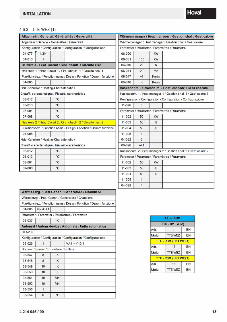
4.6.3 TTE-WEZ (1)
1
A
B
D
E
C
F
2 3 4 5 6 7 8 9
1 2 3 4 5 6 7 8 9
A
B
D
E
C
F
KAE010.dwg
Achtung ! Für die Installation muss das anlagenbezogene Schema verwendet werden!Attention! This is just a schematic. For installation please use the detail-plan!Attenzione! Per la messa in opera, utilizzare le schema dettagliato!Attention! Pour la réalisation pratique de l'installation, il faut utiliser le schéma détaillé!
Datum:
Datei:Version:
Blatt:
Par.1 Verbindungshinweise /Notice / Nota / Remarque:
7/8 4.1...
09.03.2015KAE010 Name:
134 214 045 / 00
INSTALLATION
1
A
B
D
E
C
F
2 3 4 5 6 7 8 9
1 2 3 4 5 6 7 8 9
A
B
D
E
C
F
KAE010.dwg
Achtung ! Für die Installation muss das anlagenbezogene Schema verwendet werden!Attention! This is just a schematic. For installation please use the detail-plan!Attenzione! Per la messa in opera, utilizzare le schema dettagliato!Attention! Pour la réalisation pratique de l'installation, il faut utiliser le schéma détaillé!
Datum:
Datei:Version:
Blatt:
Par.2 Verbindungshinweise /Notice / Nota / Remarque:
8/8 4.1...
09.03.2015KAE010 Name:
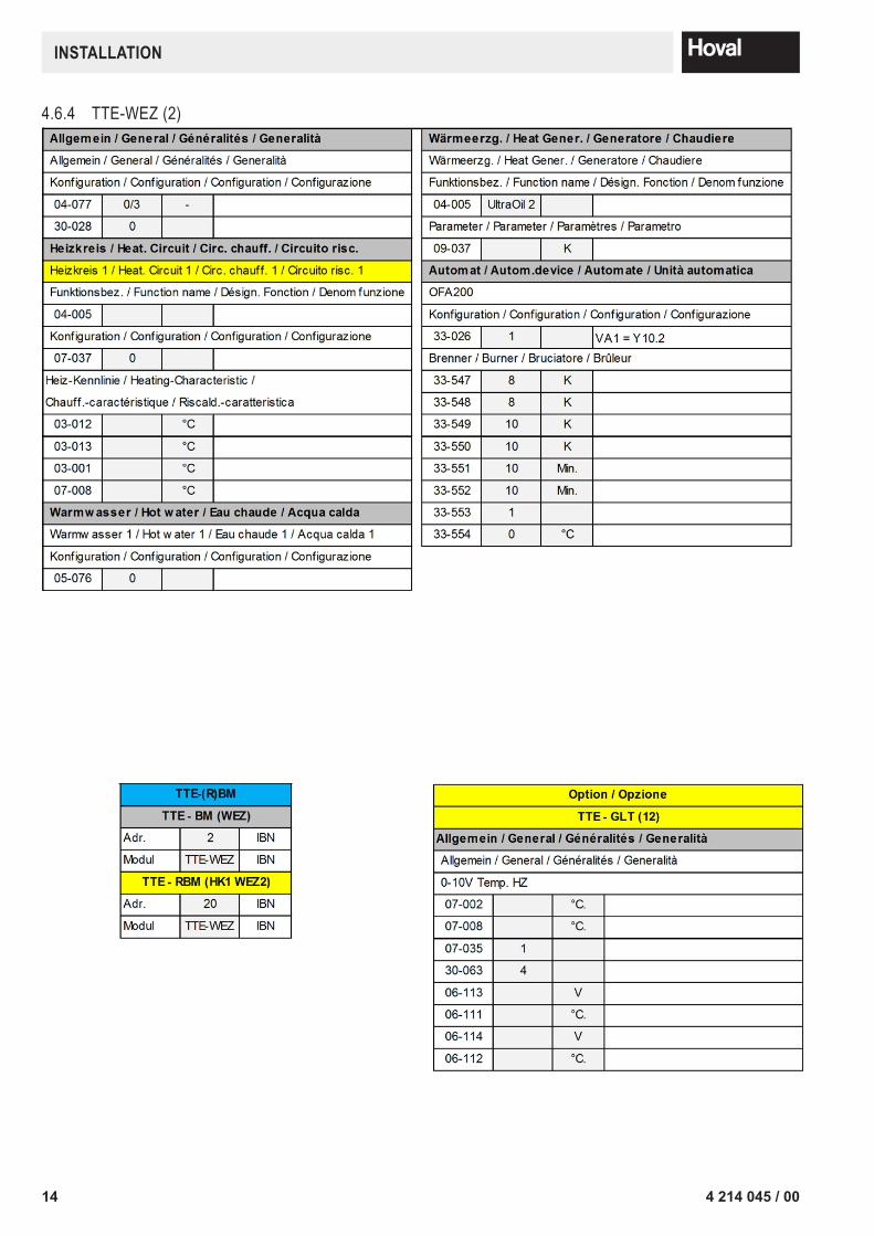
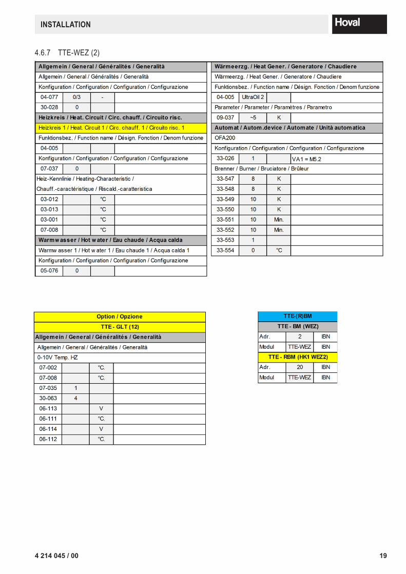
4.6.4 TTE-WEZ (2)
1
A
B
D
E
C
F
2 3 4 5 6 7 8 9
1 2 3 4 5 6 7 8 9
A
B
D
E
C
F
KAE010.dwg
Achtung ! Für die Installation muss das anlagenbezogene Schema verwendet werden!Attention! This is just a schematic. For installation please use the detail-plan!Attenzione! Per la messa in opera, utilizzare le schema dettagliato!Attention! Pour la réalisation pratique de l'installation, il faut utiliser le schéma détaillé!
Datum:
Datei:Version:
Blatt:
Par.2 Verbindungshinweise /Notice / Nota / Remarque:
8/8 4.1...
09.03.2015KAE010 Name:
14 4 214 045 / 00
INSTALLATION

4.6.5 System KAE020 Application without main pump Boiler sequential controller circuit double boiler by TTE
1
A
B
D
E
C
F
2 3 4 5 6 7 8 9
1 2 3 4 5 6 7 8 9
A
B
D
E
C
F
KAE020.dwg
Achtung ! Für die Installation muss das anlagenbezogene Schema verwendet werden!Attention! This is just a schematic. For installation please use the detail-plan!Attenzione! Per la messa in opera, utilizzare le schema dettagliato!Attention! Pour la réalisation pratique de l'installation, il faut utiliser le schéma détaillé!
Datum:
Datei:Version:
Blatt:
Hydr. Verbindungshinweise /Notice / Nota / Remarque:
1 4.1...
09.03.2015KAE020(BEDE040) Name:
Y10.1 Y10.2
TTE-WEZ
AF
RBM
TTE-GW
TTE-WEZ
M5.2M5.1
P
HT
NT
UltraOil
P
HT
NT
UltraOil
AVF
AVF
YK1
MK1
T T
B1.1VF1
SF
T
SLP T
T
DKP
T T
MK2
T T
B1.2VF2
YK2
SB-Y4OFA200
SB-Y4OFA200TTE-GLT
1
A
B
D
E
C
F
2 3 4 5 6 7 8 9
1 2 3 4 5 6 7 8 9
A
B
D
E
C
F
KAE020.dwg
Achtung ! Für die Installation muss das anlagenbezogene Schema verwendet werden!Attention! This is just a schematic. For installation please use the detail-plan!Attenzione! Per la messa in opera, utilizzare le schema dettagliato!Attention! Pour la réalisation pratique de l'installation, il faut utiliser le schéma détaillé!
Datum:
Datei:Version:
Blatt:
E1 Verbindungshinweise /Notice / Nota / Remarque:
2/8 4.1...
09.03.2015KAE020 Name:
YK1
NM1~
SLP
M1~
MK1
TTE-WEZ
L- N- L N PES1
L PE NNetz-in VA1
NLSLP
N LDKP
N LVA2
N L1N
MK1N L
B1
PENetz-outN L1
12VE1
12AF
12SF
12VF1
12VE2/IMP
-VE10V
+ +- -H1
+ ABOT
BRS485
A
T
HCAN
L +
T CAN
1
R-CAN ADR.OnOff
4 3 2 1
GB
CA
N
1
Display/Affichage(Option/opzione)
VA10V/PWM
230V~max. 4AT
10ATTTE-BM
B1.1
T
HL +
T
L H
T
(R)BM(max. 3)
BUS Verbindung zwischen den Regel-Modulen /BUS connection between the control modules /Liaison BUS entre les modules de régulation /Collegamento BUS tra i moduli di regolazione
BUS-CAN
AF SF VF1
Wärmeerzg. / Heat Gener. / Generatore / Chaudiere: 1
SHNPEL
230V / 13ANetz/Power supply/
Rete/SecteurUltra
OilÒ
£ 8
0 kW
E13.
1 / E
13.2
L PE N
0 1
SH NPEL230V / 16ANetz/Power
supply/Rete/SecteurUltra
OilÒ
³11
0 kW
E13.
3
InternOFA200
AVF
M1~
DKP
154 214 045 / 00
INSTALLATION

1
A
B
D
E
C
F
2 3 4 5 6 7 8 9
1 2 3 4 5 6 7 8 9
A
B
D
E
C
F
KAE020.dwg
Achtung ! Für die Installation muss das anlagenbezogene Schema verwendet werden!Attention! This is just a schematic. For installation please use the detail-plan!Attenzione! Per la messa in opera, utilizzare le schema dettagliato!Attention! Pour la réalisation pratique de l'installation, il faut utiliser le schéma détaillé!
Datum:
Datei:Version:
Blatt:
E2 Verbindungshinweise /Notice / Nota / Remarque:
3/8 4.1...
09.03.2015KAE020 Name:
T
B12B5B11
NL
OFA200Klemmen / Terminals / Morsetti / Bornes
L N PESK1 SK2 SK3
PE
T
B7
SK5PE N PE
VA1L
Wärmeerzg. / Heat Gener. / Generatore / Chaudiere: 1
Max. Belastung pro Ausgang / Regler: 2A / 10Acharge max. par sortie / régulateur: 2A / 10 Acarico max. per uscita / regolatore: 2A / 10 Amax. load per output / controller: 2A / 10 A3x400V Elemente sind bauseits zu versorgen-/abzusichern(z.B. Brenner, Pumpen, ....)Eléments 3x400V à fournir/sécuriser par le commettant(exemple brûleur, pompes, ... )elementi 3x400V a fornire/assicurare da parte del committente(per esempio bruciatore, pompe, ...)3x400V elements to be provided/secured by the principal(as burner, pumps, ...)
N PEY4
N PEY6
LBR1S3
sz
Verbindung zu Klemmen OFA200Connexion aux bornes de la OFA200Collegamento a morsettiera OFA200Connection to terminal block OFA200
P1L
X81 2 3 4
1 2 3 45 6
5 6
A1A2
11 1412
230V
gg
X8... SteckverbindungPlug connectionConnettore cablatoPlug connection
Y4 ... Abgasklappe (Brücke OFA entfernen)Exhaust gas damper (remove bridge OFA)Serranda fumi oppure ventilatore (asportare il ponto OFA)Clapet des gaz de combustion (enlever le pont OFA)
SB-R
1KRe
lais
/ Re
lé /
Rela
yP2N
Y4
Systembaustein SB-Y4 OFA200 /Système modulaire SB-Y4 OFA200 /
Kit a elementi SB-Y4 OFA200 /System unit SB-Y4 OFA200
PE
M5.1
M1~
T7 T8 B51 2 3
T64
L
Y10.1
M5/ Hocheffizienspumpe direkt mit Absperrklappe starten.Konventionelle Pumpen über optionalen Endschalter Absperrklappeverdrahten.(wenn offen startet Pumpe)Démarrer la pompe M5/KKP hautement efficace directement avec le clapetde fermeture. Connecter les pompes conventionnelles à travers l’interrupteurde fin de course clapet de fermeture optionnel (si ouvert, la pompe démarre).Avviare la pompa M5/KKP ad alta efficienza con la valvola a farfalla. Cablarele pompe tradizionali tramite l’interruttore valvola a farfalla opzionale (quandoè aperto si avvia la pompa).Start up the high-efficiency M5/KKP pump directly by means of the shut-offvalve. Wire the conventional pumps via the optional shut-off valve limit switch(pump starts up if open).
1
A
B
D
E
C
F
2 3 4 5 6 7 8 9
1 2 3 4 5 6 7 8 9
A
B
D
E
C
F
KAE020.dwg
Achtung ! Für die Installation muss das anlagenbezogene Schema verwendet werden!Attention! This is just a schematic. For installation please use the detail-plan!Attenzione! Per la messa in opera, utilizzare le schema dettagliato!Attention! Pour la réalisation pratique de l'installation, il faut utiliser le schéma détaillé!
Datum:
Datei:Version:
Blatt:
E3 Verbindungshinweise /Notice / Nota / Remarque:
4/8 4.1...
09.03.2015KAE020 Name:
TTE-WEZ
L- N- L N PES1
L PE NNetz-in VA1
NLSLP
N LDKP
N LVA2
N L1N
MK1N L
B1
PENetz-outN L1
12VE1
12AF
12SF
12VF1
12VE2/IMP
-VE10V
+ +- -H1
+ ABOT
BRS485
A
T
HCAN
L +
T CAN
1
R-CAN ADR.OnOff
4 3 2 1
GB
CA
N
1
Display/Affichage(Option/opzione)
VA10V/PWM
230V~max. 4AT
10ATTTE-BM
AN
HL +
T
L H
T
(R)BM(max. 3)
BUS Verbindung zwischen den Regel-Modulen /BUS connection between the control modules /Liaison BUS entre les modules de régulation /Collegamento BUS tra i moduli di regolazione
BUS-CAN
Wärmeerzg. / Heat Gener. / Generatore / Chaudiere: 2
SHNPEL
230V / 13ANetz/Power supply/
Rete/SecteurUltra
OilÒ
£ 8
0 kW
E13.
1 / E
13.2
L PE N
0 1
SH NPEL230V / 16ANetz/Power
supply/Rete/SecteurUltra
OilÒ
³11
0 kW
E13.
3
InternOFA200
T
YK2
N M1~
MK2 B1.2
VF2
16 4 214 045 / 00
INSTALLATION

1
A
B
D
E
C
F
2 3 4 5 6 7 8 9
1 2 3 4 5 6 7 8 9
A
B
D
E
C
F
KAE020.dwg
Achtung ! Für die Installation muss das anlagenbezogene Schema verwendet werden!Attention! This is just a schematic. For installation please use the detail-plan!Attenzione! Per la messa in opera, utilizzare le schema dettagliato!Attention! Pour la réalisation pratique de l'installation, il faut utiliser le schéma détaillé!
Datum:
Datei:Version:
Blatt:
E4 Verbindungshinweise /Notice / Nota / Remarque:
5/8 4.1...
09.03.2015KAE020 Name:
T
B12B5B11
NL
OFA200Klemmen / Terminals / Morsetti / Bornes
L N PESK1 SK2 SK3
PE
T
B7
SK5PE N PE
VA1L
Wärmeerzg. / Heat Gener. / Generatore / Chaudiere: 2
Max. Belastung pro Ausgang / Regler: 2A / 10Acharge max. par sortie / régulateur: 2A / 10 Acarico max. per uscita / regolatore: 2A / 10 Amax. load per output / controller: 2A / 10 A3x400V Elemente sind bauseits zu versorgen-/abzusichern(z.B. Brenner, Pumpen, ....)Eléments 3x400V à fournir/sécuriser par le commettant(exemple brûleur, pompes, ... )elementi 3x400V a fornire/assicurare da parte del committente(per esempio bruciatore, pompe, ...)3x400V elements to be provided/secured by the principal(as burner, pumps, ...)
N PEY4
N PEY6
LBR1S3
sz
Verbindung zu Klemmen OFA200Connexion aux bornes de la OFA200Collegamento a morsettiera OFA200Connection to terminal block OFA200
P1L
X81 2 3 4
1 2 3 45 6
5 6
A1A2
11 1412
230V
gg
X8... SteckverbindungPlug connectionConnettore cablatoPlug connection
Y4 ... Abgasklappe (Brücke OFA entfernen)Exhaust gas damper (remove bridge OFA)Serranda fumi oppure ventilatore (asportare il ponto OFA)Clapet des gaz de combustion (enlever le pont OFA)
SB-R
1KRe
lais
/ Re
lé /
Rela
y
P2NY4
Systembaustein SB-Y4 OFA200 /Système modulaire SB-Y4 OFA200 /
Kit a elementi SB-Y4 OFA200 /System unit SB-Y4 OFA200
PE
M5.2
M1~
T7 T8 B51 2 3
T64
L
Y10.2
M5/ Hocheffizienspumpe direkt mit Absperrklappe starten.Konventionelle Pumpen über optionalen Endschalter Absperrklappeverdrahten.(wenn offen startet Pumpe)Démarrer la pompe M5/KKP hautement efficace directement avec le clapetde fermeture. Connecter les pompes conventionnelles à travers l’interrupteurde fin de course clapet de fermeture optionnel (si ouvert, la pompe démarre).Avviare la pompa M5/KKP ad alta efficienza con la valvola a farfalla. Cablarele pompe tradizionali tramite l’interruttore valvola a farfalla opzionale (quandoè aperto si avvia la pompa).Start up the high-efficiency M5/KKP pump directly by means of the shut-offvalve. Wire the conventional pumps via the optional shut-off valve limit switch(pump starts up if open).
1
A
B
D
E
C
F
2 3 4 5 6 7 8 9
1 2 3 4 5 6 7 8 9
A
B
D
E
C
F
KAE020.dwg
Achtung ! Für die Installation muss das anlagenbezogene Schema verwendet werden!Attention! This is just a schematic. For installation please use the detail-plan!Attenzione! Per la messa in opera, utilizzare le schema dettagliato!Attention! Pour la réalisation pratique de l'installation, il faut utiliser le schéma détaillé!
Datum:
Datei:Version:
Blatt:
E5 Verbindungshinweise /Notice / Nota / Remarque:
6/8 4.1...
09.03.2015KAE020 Name:
TTE-GLT
L PE NNetz-in VA1 / VA2
NVA3
N L PENetz-outN L1
12VE1
12VE2
12VE3/IMP
-VE10V
+ +- HCAN
L +
T
VA10V/PWM
10AT
FFVT
+ T
T
L L
230V~max. 4AT
R-CAN GBOnOff
Adr.On
4 3 2 1
SK-VA3
ID
HL
T
BUS Verbindung zwischen den Regel-Modulen /BUS connection between the control modules /Liaison BUS entre les modules de régulation /Collegamento BUS tra i moduli di regolazione
BUS-CAN
VE10V
Option / opzione : GLT/BMS/GTC Modul 0-10V(im Wärmeerzg. 1 / in Heat Gener. 1 / in Generatore 1 / en Chaudiere 1 )
230V~TTE-WEZ
5 10
50
100
0
° C
0V
2
1
Variante/Variant:Temperaturregelung extern mit 0-10VExternal temperature control with 0-10VRegiolazione temperatura esterno con 0-10VRégulation externe de la température avec 0-10V
0V - 0.5V... Sollwert 0 Setvalue 0 Valeur prévu 0 Valore nominale 0
0.5V - 10.0V... Sollwert 5°C - 100°C Setvalue 5°C - 100°C Valeur prévu 5°C - 100°C Valore nominale 5°C - 100°C
Arbeitspunkte 1,2 veränderbarOperating points 1,2 adjustablePoints de fonctionnement 1,2 réglablesPunti di funzionamento 1,2 regolabili
Externe Anforderung (GLT)External requirement (BMS)Demand externe (GTC)Richiesta esterna (BMS)
174 214 045 / 00
INSTALLATION

1
A
B
D
E
C
F
2 3 4 5 6 7 8 9
1 2 3 4 5 6 7 8 9
A
B
D
E
C
F
KAE020.dwg
Achtung ! Für die Installation muss das anlagenbezogene Schema verwendet werden!Attention! This is just a schematic. For installation please use the detail-plan!Attenzione! Per la messa in opera, utilizzare le schema dettagliato!Attention! Pour la réalisation pratique de l'installation, il faut utiliser le schéma détaillé!
Datum:
Datei:Version:
Blatt:
Par.1 Verbindungshinweise /Notice / Nota / Remarque:
7/8 4.1...
09.03.2015KAE020 Name:
4.6.6 TTE-WEZ (1)
1
A
B
D
E
C
F
2 3 4 5 6 7 8 9
1 2 3 4 5 6 7 8 9
A
B
D
E
C
F
KAE020.dwg
Achtung ! Für die Installation muss das anlagenbezogene Schema verwendet werden!Attention! This is just a schematic. For installation please use the detail-plan!Attenzione! Per la messa in opera, utilizzare le schema dettagliato!Attention! Pour la réalisation pratique de l'installation, il faut utiliser le schéma détaillé!
Datum:
Datei:Version:
Blatt:
Par.1 Verbindungshinweise /Notice / Nota / Remarque:
7/8 4.1...
09.03.2015KAE020 Name:
18 4 214 045 / 00
INSTALLATION
4.6.7 TTE-WEZ (2)1
A
B
D
E
C
F
2 3 4 5 6 7 8 9
1 2 3 4 5 6 7 8 9
A
B
D
E
C
F
KAE020.dwg
Achtung ! Für die Installation muss das anlagenbezogene Schema verwendet werden!Attention! This is just a schematic. For installation please use the detail-plan!Attenzione! Per la messa in opera, utilizzare le schema dettagliato!Attention! Pour la réalisation pratique de l'installation, il faut utiliser le schéma détaillé!
Datum:
Datei:Version:
Blatt:
Par.2 Verbindungshinweise /Notice / Nota / Remarque:
8/8 4.1...
09.03.2015KAE020 Name:
1
A
B
D
E
C
F
2 3 4 5 6 7 8 9
1 2 3 4 5 6 7 8 9
A
B
D
E
C
F
KAE020.dwg
Achtung ! Für die Installation muss das anlagenbezogene Schema verwendet werden!Attention! This is just a schematic. For installation please use the detail-plan!Attenzione! Per la messa in opera, utilizzare le schema dettagliato!Attention! Pour la réalisation pratique de l'installation, il faut utiliser le schéma détaillé!
Datum:
Datei:Version:
Blatt:
Par.2 Verbindungshinweise /Notice / Nota / Remarque:
8/8 4.1...
09.03.2015KAE020 Name:
194 214 045 / 00
INSTALLATION
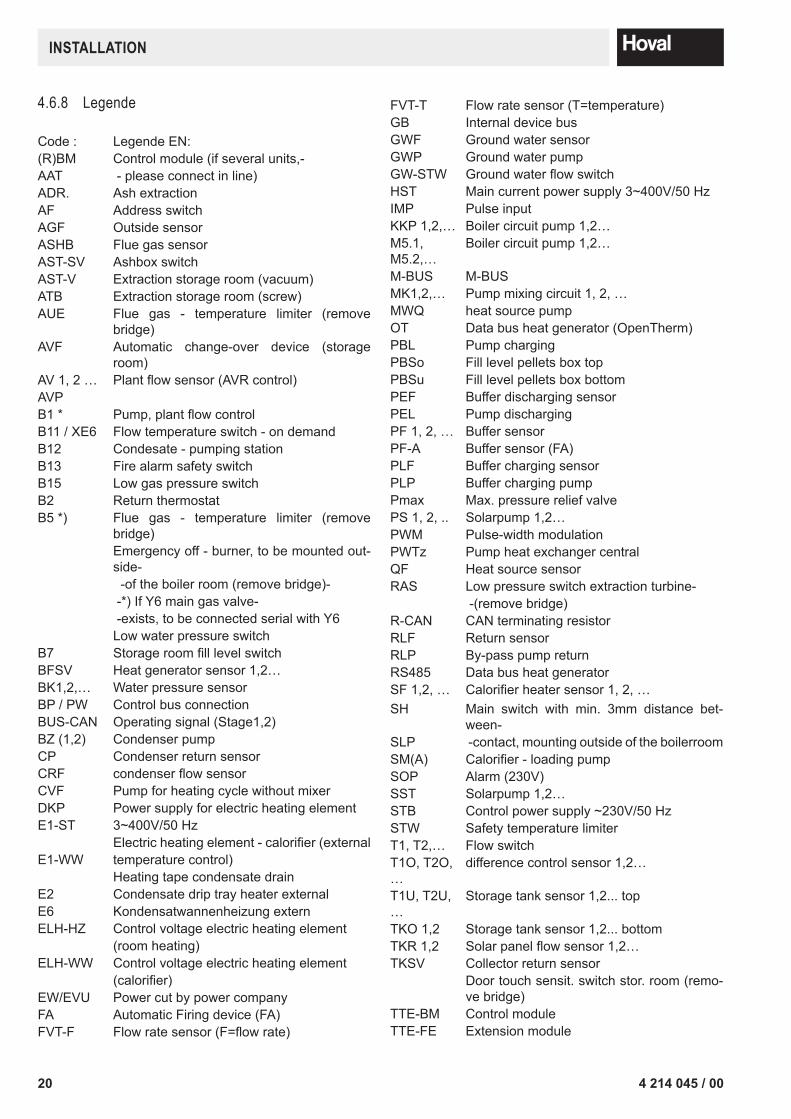
4.6.8 Legende
Code : Legende EN:(R)BM Control module (if several units,- AAT - please connect in line)ADR. Ash extractionAF Address switchAGF Outside sensorASHB Flue gas sensorAST-SV Ashbox switchAST-V Extraction storage room (vacuum)ATB Extraction storage room (screw)AUE Flue gas - temperature limiter (remove
bridge)AVF Automatic change-over device (storage
room)AV 1, 2 … Plantflowsensor(AVRcontrol)AVPB1 * Pump,plantflowcontrolB11 / XE6 Flow temperature switch - on demandB12 Condesate - pumping stationB13 Fire alarm safety switchB15 Low gas pressure switchB2 Return thermostatB5 *) Flue gas - temperature limiter (remove
bridge)Emergency off - burner, to be mounted out-side- -of the boiler room (remove bridge)- -*) If Y6 main gas valve- -exists, to be connected serial with Y6Low water pressure switch
B7 StorageroomfilllevelswitchBFSV Heat generator sensor 1,2…BK1,2,… Water pressure sensorBP / PW Control bus connectionBUS-CAN Operating signal (Stage1,2)BZ (1,2) Condenser pumpCP Condenser return sensorCRF condenserflowsensorCVF Pump for heating cycle without mixerDKP Power supply for electric heating element E1-ST 3~400V/50 Hz
Electricheatingelement-calorifier(externalE1-WW temperature control)
Heating tape condensate drainE2 Condensate drip tray heater externalE6 Kondensatwannenheizung externELH-HZ Control voltage electric heating element
(room heating)ELH-WW Control voltage electric heating element
(calorifier)EW/EVU Power cut by power company FA Automatic Firing device (FA)FVT-F Flowratesensor(F=flowrate)
FVT-T Flow rate sensor (T=temperature)GB Internal device busGWF Ground water sensorGWP Ground water pumpGW-STW GroundwaterflowswitchHST Main current power supply 3~400V/50 HzIMP Pulse inputKKP 1,2,… Boiler circuit pump 1,2…M5.1, M5.2,…
Boiler circuit pump 1,2…
M-BUS M-BUSMK1,2,… Pump mixing circuit 1, 2, …MWQ heat source pumpOT Data bus heat generator (OpenTherm)PBL Pump chargingPBSo Fill level pellets box topPBSu Fill level pellets box bottomPEF Buffer discharging sensorPEL Pump dischargingPF 1, 2, … Buffer sensorPF-A Buffer sensor (FA)PLF Buffer charging sensorPLP Buffer charging pumpPmax Max. pressure relief valvePS 1, 2, .. Solarpump 1,2…PWM Pulse-width modulationPWTz Pump heat exchanger centralQF Heat source sensorRAS Low pressure switch extraction turbine-
-(remove bridge)R-CAN CAN terminating resistorRLF Return sensorRLP By-pass pump returnRS485 Data bus heat generatorSF 1,2, … Calorifierheatersensor1,2,…SH Main switch with min. 3mm distance bet-
ween-SLP -contact, mounting outside of the boilerroom SM(A) Calorifier-loadingpumpSOP Alarm (230V)SST Solarpump 1,2…STB Control power supply ~230V/50 HzSTW Safety temperature limiterT1, T2,… Flow switchT1O, T2O, …
difference control sensor 1,2…
T1U, T2U, …
Storage tank sensor 1,2... top
TKO 1,2 Storage tank sensor 1,2... bottomTKR 1,2 Solarpanelflowsensor1,2…TKSV Collector return sensor
Door touch sensit. switch stor. room (remo-ve bridge)
TTE-BM Control moduleTTE-FE Extension module
20 4 214 045 / 00
INSTALLATION
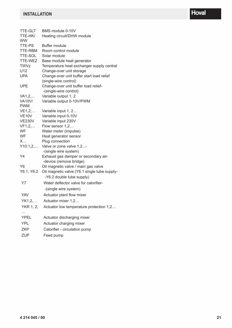
TTE-GLT BMS module 0-10VTTE-HK/WW
Heating circuit/DHW module
TTE-PS Buffer moduleTTE-RBM Room control moduleTTE-SOL Solar moduleTTE-WEZ Base module heat generatorTWVz Temperature heat exchanger supply centralU12 Change-over unit storageUPA Change-over unit buffer start load relief
(single-wire control)UPE Change-over unit buffer load relief-
-(single-wire control)VA1,2,... Variable output 1, 2VA10V/PWM
Variable output 0-10V/PWM
VE1,2,… Variable input 1, 2…VE10V Variable input 0-10VVE230V Variable input 230VVF1,2,… Flow sensor 1,2…WF Water meter (impulse)WF Heat generator sensorX… Plug connectionY10.1,2,… Valve or zone valve 1,2...-
-(single wire system)Y4 Exhaust gas damper or secondary air-
-device (remove bridge)Y6 Oil magnetic valve / main gas valveY6.1, Y6.2 Oil magnetic valve (Y6.1 single tube supply-
-Y6.2 double tube supply)Y7 Waterdeflectorvalveforcalorifier-
-(single wire system)YAV ActuatorplantflowmixerYK1,2,… Actuator mixer 1,2…YKR 1, 2, …
Actuator low temperature protection 1,2…
YPEL Actuator discharging mixerYPL Actuator charging mixerZKP Calorifier-circulationpumpZUP Feed pump
214 214 045 / 00
INSTALLATION

22 4 214 045 / 00

234 214 045 / 00

Confirmation
The user (owner) of the system herewith confi rms that• he has received adequate instruction in the operating and maintenance of the installation,• received and taken note of the operating and maintenance instructions and, where applicable other documents con-
cerning the heat generator and any further components.• and is consequently suffi ciently familiar with the installation.
Installation address: Type:
Serial number:
Year of manufacture:
Place, Date:
System installer: System user:
COPY FOR PLANT USER
COPY OF SYSTEM INSTALLER
Related Documents