Ultra-high-capacity wireless communication by means of steered narrow optical beams Citation for published version (APA): Koonen, A. M. J., Mekonnen, K. A., Cao, Z., Huijskens, F. M., Pham, N., & Tangdiongga, E. (2020). Ultra-high- capacity wireless communication by means of steered narrow optical beams. Philosophical Transactions of the Royal Society of London, Series A: Mathematical, Physical and Engineering Sciences, 378(2169), [20190192]. https://doi.org/10.1098/rsta.2019.0192 Document license: TAVERNE DOI: 10.1098/rsta.2019.0192 Document status and date: Published: 17/04/2020 Document Version: Publisher’s PDF, also known as Version of Record (includes final page, issue and volume numbers) Please check the document version of this publication: • A submitted manuscript is the version of the article upon submission and before peer-review. There can be important differences between the submitted version and the official published version of record. People interested in the research are advised to contact the author for the final version of the publication, or visit the DOI to the publisher's website. • The final author version and the galley proof are versions of the publication after peer review. • The final published version features the final layout of the paper including the volume, issue and page numbers. Link to publication General rights Copyright and moral rights for the publications made accessible in the public portal are retained by the authors and/or other copyright owners and it is a condition of accessing publications that users recognise and abide by the legal requirements associated with these rights. • Users may download and print one copy of any publication from the public portal for the purpose of private study or research. • You may not further distribute the material or use it for any profit-making activity or commercial gain • You may freely distribute the URL identifying the publication in the public portal. If the publication is distributed under the terms of Article 25fa of the Dutch Copyright Act, indicated by the “Taverne” license above, please follow below link for the End User Agreement: www.tue.nl/taverne Take down policy If you believe that this document breaches copyright please contact us at: [email protected] providing details and we will investigate your claim. Download date: 20. Sep. 2022

Welcome message from author
This document is posted to help you gain knowledge. Please leave a comment to let me know what you think about it! Share it to your friends and learn new things together.
Transcript

Ultra-high-capacity wireless communication by means ofsteered narrow optical beamsCitation for published version (APA):Koonen, A. M. J., Mekonnen, K. A., Cao, Z., Huijskens, F. M., Pham, N., & Tangdiongga, E. (2020). Ultra-high-capacity wireless communication by means of steered narrow optical beams. Philosophical Transactions of theRoyal Society of London, Series A: Mathematical, Physical and Engineering Sciences, 378(2169), [20190192].https://doi.org/10.1098/rsta.2019.0192
Document license:TAVERNE
DOI:10.1098/rsta.2019.0192
Document status and date:Published: 17/04/2020
Document Version:Publisher’s PDF, also known as Version of Record (includes final page, issue and volume numbers)
Please check the document version of this publication:
• A submitted manuscript is the version of the article upon submission and before peer-review. There can beimportant differences between the submitted version and the official published version of record. Peopleinterested in the research are advised to contact the author for the final version of the publication, or visit theDOI to the publisher's website.• The final author version and the galley proof are versions of the publication after peer review.• The final published version features the final layout of the paper including the volume, issue and pagenumbers.Link to publication
General rightsCopyright and moral rights for the publications made accessible in the public portal are retained by the authors and/or other copyright ownersand it is a condition of accessing publications that users recognise and abide by the legal requirements associated with these rights.
• Users may download and print one copy of any publication from the public portal for the purpose of private study or research. • You may not further distribute the material or use it for any profit-making activity or commercial gain • You may freely distribute the URL identifying the publication in the public portal.
If the publication is distributed under the terms of Article 25fa of the Dutch Copyright Act, indicated by the “Taverne” license above, pleasefollow below link for the End User Agreement:www.tue.nl/taverne
Take down policyIf you believe that this document breaches copyright please contact us at:[email protected] details and we will investigate your claim.
Download date: 20. Sep. 2022

royalsocietypublishing.org/journal/rsta
ReviewCite this article: Koonen T, Mekonnen K, CaoZ, Huijskens F, Pham NQ, Tangdiongga E. 2020Ultra-high-capacity wireless communicationby means of steered narrow optical beams.Phil. Trans. R. Soc. A 378: 20190192.http://dx.doi.org/10.1098/rsta.2019.0192
Accepted: 21 October 2019
One contribution of 17 to a theme issue‘Optical wireless communication’.
Subject Areas:electrical engineering, optics
Keywords:optical wireless communication, beamsteering, broadband wireless communication
Author for correspondence:Ton Koonene-mail: [email protected]
Ultra-high-capacity wirelesscommunication by means ofsteered narrow optical beamsTon Koonen, KetemawMekonnen, Zizheng Cao, Frans
Huijskens, Ngoc Quan Pham and Eduward
Tangdiongga
Institute for Photonic Integration, Eindhoven University ofTechnology, Eindhoven, The Netherlands
TK, 0000-0003-2466-7961
The optical spectrum offers great opportunities toresolve the congestion in radio-based communication,aggravated by the booming demand for wirelessconnectivity. High-speed infrared optical componentsin the 1500 nm window have reached high levelsof sophistication and are extensively used alreadyin fibre-optic networks. Moreover, infrared lightbeyond 1400 nm is eye-safe and is not noticeableby the users. Deploying steerable narrow infraredbeams, wireless links with huge capacity can beestablished to users individually, at minimum powerconsumption levels and at very high levels of privacy.Fully passive diffractive optical modules can handlemany beams individually and accurately steer narrowbeams two-dimensionally by just remotely tuning thewavelength of each beam. The system design aspectsare discussed, encompassing the beam-steeringtransmitter, wide field-of-view optical receiverand the localization of the user’s wireless devices.Prototype system demonstrators are reported, capableof supporting up to 128 beams carrying up to112 Gbit s−1 per beam. Hybrid bidirectional systemswhich use a high-speed downstream optical linkand an upstream radio link at a lower speed canprovide powerful asymmetric wireless connections.All-optical bidirectional beam-steered wirelesscommunication will be able to offer the ultimate inwireless capacity to the user while minimizing powerconsumption.
This article is part of the theme issue ‘Opticalwireless communication’.
2020 The Author(s) Published by the Royal Society. All rights reserved.
2
royalsocietypublishing.org/journal/rstaPhil.Trans.R.Soc.A378:20190192
...............................................................
1. IntroductionThe world of wireless communication is seeing exploding growth, and we increasingly depend onit in our professional and private life. We need to get and stay connected always and everywhere,including sometimes in urgent critical circumstances. The internet has become our lifeline, and thevast majority of communications run over it. We highly value being able to move freely, withoutbeing hampered by connections through wires, hence wireless communication has become ourmain modus of being connected. The majority of the traffic on the internet emerges from indoorlocations (more than 85% has been reported), and today wireless local area networks such asthe IEEE802.11-based ones (a.k.a. WiFi) are taking care of this. Also, public mobile networks,such as the earlier 2G (GSM) and 3G (UMTS) networks originally laid out for voice and instantmessaging (sms), and the current 4G (LTE) networks supporting in addition higher data speeds,are handling much wireless traffic. The upcoming 5G networks promise another step forward, notonly towards more than tenfold increase in data capacity per user, but also towards drasticallyreducing latency which becomes ever more important in time-critical machine-to-machine andhuman-to-machine communication (e.g. autonomous cars).
While radio-based communication technologies are fiercely trying to keep up with thebooming demands for wireless connectivity, this challenge is becoming more and more difficultto meet. As stated in Cooper’s Law (http://www.arraycomm.com/technology/coopers-law/),the enormous growth in wireless communication capabilities with a factor of about 1 millionin the past 45 years has partly (by roughly a factor of 5×) been achieved by introducing evermore powerful signal modulation techniques in order to squeeze more data capacity in a limitedfrequency band. Another factor of 5× has been attained by introducing frequency divisionmultiplexing techniques in order to fit these bands into a limited spectrum. And opening upmore radio spectrum yielded another factor of about 25×. The remaining factor of 1600× has beenachieved by so-called spatial multiplexing: by making the radio cells covered by an antenna eversmaller, more and more antennas can serve the same area. Thus, the number of users to be servedby a cell decreases and each user can get higher capacity. Within each cell, with respect to thesurrounding cells, the radio spectrum can be re-used (provided that cross-talk between the cellsis managed, e.g. by not allowing the same frequency band to be used in the neighbouring cells).Basically, this spatial multiplexing approach is the key solution to meet exponentially growingcapacity demands; halving the cell size doubles the network’s aggregate capacity. It is enhancedby introducing ever smaller pico-cells.
This article discusses how optical technologies, next to having proven their great capabilities inwired communication networks (through optical fibres), also have a great potential in addressingthe challenges in wireless communication. It in particular addresses how wireless communicationby means of dynamically steered narrow infrared beams can disclose huge capacities to the userswhile also providing high energy efficiency and enhanced privacy.
2. Optical wireless communicationDespite all the above-mentioned efforts made by radio technologies, the ongoing growth ofwireless communication traffic is driving the radio spectrum into congestion. The opticalspectrum can offer a huge amount of extra room, with ample opportunities for high-capacitycommunication as has been impressively shown by optical fibre transmission techniques.
The spectrum of visible light, roughly from 400 to 700 nm, represents no less than 320 THzof bandwidth, way beyond what the THz radio technologies being investigated can attain.Light-emitting diode (LED) illumination systems have been introduced widely; next to givinglight for illumination, a LED can also convey data after being modulated (albeit with restrictedbandwidth). In its networked version (known as light fidelity (LiFi) [1]), it can offer highercapacities. Also the spectrum of infrared light as used for high-speed long-reach optical fibrecommunication, roughly from 1500 to 1600 nm, represents a sizable 12.5 THz of bandwidth.For the latter, there is a wealth of mature high-speed optical devices available (laser diodes,
3
royalsocietypublishing.org/journal/rstaPhil.Trans.R.Soc.A378:20190192
...............................................................
anterior chamberaqueous body
corneapupil
light
lens
ciliary body
suspensoryligament vitreous body
optic nerve
blood vessels
optic discblind spot
iris
fovea
retina
choroid
sclera
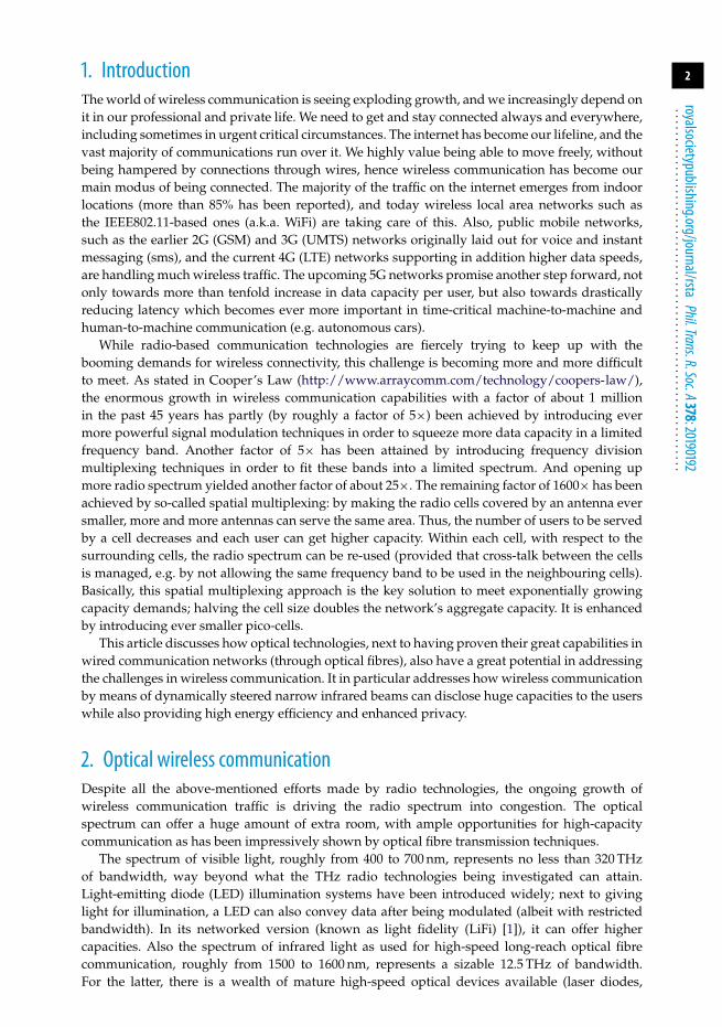
Figure 1. Light incident onto the human eye. (Online version in colour.)
photodetectors, optical modulators, etc.) already developed by the optical fibre systems domain.Optical wireless communication may advantageously build on that legacy [2–4].
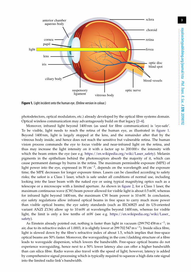
Moreover, infrared light beyond 1400 nm (as used for fibre communication) is ‘eye-safe’.To be visible, light needs to reach the retina of the human eye, as illustrated in figure 1.Beyond 1400 nm, light is largely stopped at the lens, and the remainder after that by thevitreous body inside, and hence does not reach the sensitive but vulnerable retina. The humanvision process commands the eye to focus visible and near-infrared light on the retina, andthus may increase the light intensity on it with a factor up to 200 000× the intensity withwhich the beam enters the eye (see e.g. https://en.wikipedia.org/wiki/Laser_safety). Melaninpigments in the epithelium behind the photoreceptors absorb the majority of it, which cancause permanent damage by burns in the retina. The maximum permissible exposure (MPE) oflight power into the eye, expressed in W cm−2, depends on the wavelength and the exposuretime; the MPE decreases for longer exposure times. Lasers can be classified according to safetyrisks; the safest is a Class 1 laser, which is safe under all conditions of normal use, includinglooking into the laser beam with the naked eye or using typical magnifying optics such as atelescope or a microscope with a limited aperture. As shown in figure 2, for a Class 1 laser, themaximum continuous wave (CW) beam power allowed for visible light is about 0.5 mW, whereasfor infrared light beyond 1400 nm, the maximum CW beam power is 10 mW. In conclusion,eye safety regulations allow infrared optical beams in free space to carry much more powerthan visible optical beams; the eye safety standards (such as IEC60825 and its US-orientedvariant ANZI Z136) allow up to 10 mW at wavelengths beyond 1400 nm, whereas for visiblelight, the limit is only a few tenths of mW (see e.g. https://en.wikipedia.org/wiki/Laser_safety).
As Einstein already pointed out, nothing is faster than light in vacuum (299 792 458 m s−1; inair, due to its refractive index of 1.0003, it is slightly lower at 299 702 547 m s−1). Inside silica fibre,light is slowed down by the fibre’s refractive index of about 1.5, which implies that free-spaceoptical beams are 50% faster. Moreover, the waveguiding in the core/cladding structure of a fibreleads to waveguide dispersion, which lowers the bandwidth. Free-space optical beams do notexperience waveguiding, hence next to a 50% lower latency also can offer a higher bandwidththan can silica fibre. Radio waves also travel with the speed of light; however, latency is addedby comprehensive signal processing which is typically required to squeeze a high data rate signalinto the limited radio link’s bandwidth.

4
royalsocietypublishing.org/journal/rstaPhil.Trans.R.Soc.A378:20190192
...............................................................
1000
0.001300 400 500 600 700 800 900 1000
wavelength (nm)
max
imal
allo
wed
cw
pow
er (
mW
)
1100 1200 1300 1400 1500 1600 1700
class 3B
class 3R
class 2
class 1
0.01
0.1
1
10
100
Figure 2. Maximum allowed CW powers for the laser classes 1, 2, 3R and 3B according to the standard EN 60825-1:2007 (note:only for static, point-like laser sources, i.e. collimated or weakly divergent laser beams) (see e.g. https://en.wikipedia.org/wiki/Laser_safety). (Online version in colour.)
Next to providing a wealth of extra spectrum, a major benefit of optical wirelesscommunication is its ability to be confined to narrow beams of light. By means of optical elementssuch as lenses and mirrors, optical beams can be collimated into small cross-sections and staynarrow over a long reach. Optical beams are being used for linking satellites in outer spacewhich are thousands of kilometres apart. Optical beams are par excellence suited to create pico-cells, which as Cooper’s Law also pointed out are the key to meet exponentially growing trafficdemands. Moreover, the confinement of an optical beam implies that it can be directed such thatit only reaches the user(s) for which it is meant; other users cannot get it and hence cannot tap in.Hence communication by narrow optical beams provides inherently better privacy than the widerradio beams. And an optical beam directs its power only to the intended destination; it does notspoil it elsewhere. Hence communication by optical beams is inherently more energy efficientthan that by radio beams. This high directivity also means that the user receives a significantlyhigher fraction of the signal power emitted by the transmitter station, and therefore the signal-to-noise ratio (SNR) is much better. As Shannon’s Law states, the maximum attainable capacity of acommunication link is given by C = B · log2 (1 + SNR) in bits/second, where B is the bandwidthof the channel. With the increased SNR and the high bandwidth B of the optical wireless link,the link can carry a significantly higher capacity. At the expense of comprehensive phased arrayantenna structures supported by complex signal processing, also radio waves can be tailoredinto smaller shapes and get more directive. For 5G networks, so-called massive multiple inputmultiple output antennas are foreseen, where e.g. no less than 1000 antenna elements are neededto provide a directivity gain of 30 dBi with respect to an omni-directional antenna. For opticalwireless communication, however, collimating the light beam by simple passive optical devicessuch as a single lens or concave mirror can easily yield a directivity gain which is much higherthan 40 dBi.
Optical wireless links need a clear line-of-sight (LoS) between the transmitter and the user’sreceiver, which is a disadvantage with regard to radio wireless links operating at low to moderatefrequencies (such as wireless LAN systems working at 2.5 and 5 GHz). Millimetre-wave radiosystems, such as those at 60 GHz, have a wider bandwidth (some 7 GHz at 60 GHz carrierfrequency), but also suffer from severe attenuation if their link does not have a free LoS. On theother hand, the necessity of LoS also means that optical wireless communication cannot penetratewalls, so it provides good privacy without additional encryption measures as are needed inwireless LAN links.
5
royalsocietypublishing.org/journal/rstaPhil.Trans.R.Soc.A378:20190192
...............................................................
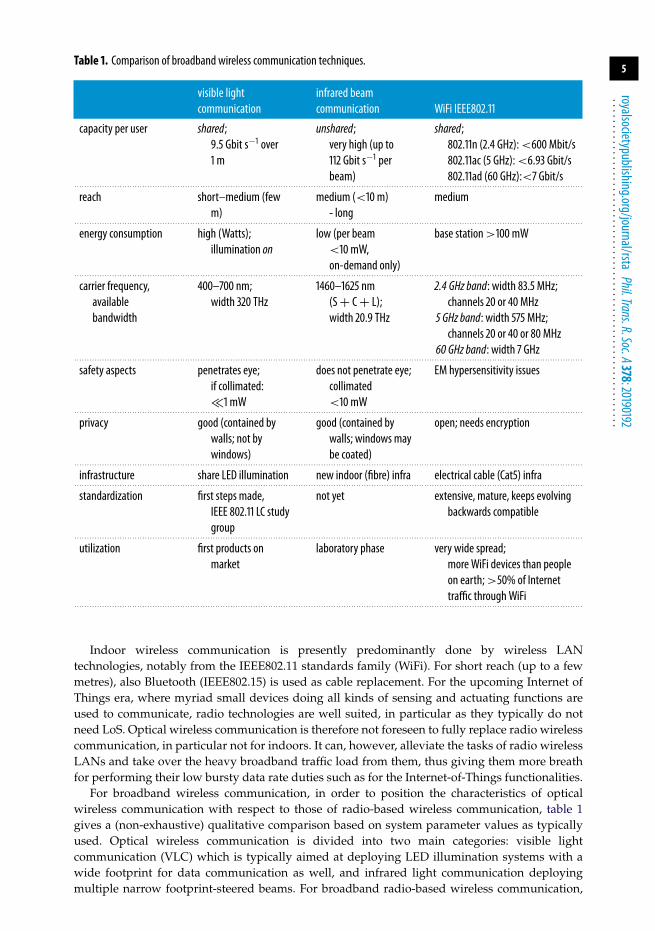
Table 1. Comparison of broadband wireless communication techniques.
visible lightcommunication
infrared beamcommunication WiFi IEEE802.11
capacity per user shared;9.5 Gbit s−1 over1 m
unshared;very high (up to112 Gbit s−1 perbeam)
shared;802.11n (2.4 GHz):<600 Mbit/s802.11ac (5 GHz):<6.93 Gbit/s802.11ad (60 GHz):<7 Gbit/s
. . . . . . . . . . . . . . . . . . . . . . . . . . . . . . . . . . . . . . . . . . . . . . . . . . . . . . . . . . . . . . . . . . . . . . . . . . . . . . . . . . . . . . . . . . . . . . . . . . . . . . . . . . . . . . . . . . . . . . . . . . . . . . . . . . . . . . . . . . . . . . . . . . . . . . . . . . . . . . . . . . . . . . . . . . . . . . . . . . . . . . . . . . . . . . . . . . . . . . . . . .
reach short–medium (fewm)
medium (<10 m)- long
medium
. . . . . . . . . . . . . . . . . . . . . . . . . . . . . . . . . . . . . . . . . . . . . . . . . . . . . . . . . . . . . . . . . . . . . . . . . . . . . . . . . . . . . . . . . . . . . . . . . . . . . . . . . . . . . . . . . . . . . . . . . . . . . . . . . . . . . . . . . . . . . . . . . . . . . . . . . . . . . . . . . . . . . . . . . . . . . . . . . . . . . . . . . . . . . . . . . . . . . . . . . .
energy consumption high (Watts);illumination on
low (per beam<10 mW,on-demand only)
base station>100 mW
. . . . . . . . . . . . . . . . . . . . . . . . . . . . . . . . . . . . . . . . . . . . . . . . . . . . . . . . . . . . . . . . . . . . . . . . . . . . . . . . . . . . . . . . . . . . . . . . . . . . . . . . . . . . . . . . . . . . . . . . . . . . . . . . . . . . . . . . . . . . . . . . . . . . . . . . . . . . . . . . . . . . . . . . . . . . . . . . . . . . . . . . . . . . . . . . . . . . . . . . . .
carrier frequency,availablebandwidth
400–700 nm;width 320 THz
1460–1625 nm(S+ C+ L);width 20.9 THz
2.4 GHz band: width 83.5 MHz;channels 20 or 40 MHz
5 GHz band: width 575 MHz;channels 20 or 40 or 80 MHz
60 GHz band: width 7 GHz. . . . . . . . . . . . . . . . . . . . . . . . . . . . . . . . . . . . . . . . . . . . . . . . . . . . . . . . . . . . . . . . . . . . . . . . . . . . . . . . . . . . . . . . . . . . . . . . . . . . . . . . . . . . . . . . . . . . . . . . . . . . . . . . . . . . . . . . . . . . . . . . . . . . . . . . . . . . . . . . . . . . . . . . . . . . . . . . . . . . . . . . . . . . . . . . . . . . . . . . . .
safety aspects penetrates eye;if collimated:�1 mW
does not penetrate eye;collimated<10 mW
EM hypersensitivity issues
. . . . . . . . . . . . . . . . . . . . . . . . . . . . . . . . . . . . . . . . . . . . . . . . . . . . . . . . . . . . . . . . . . . . . . . . . . . . . . . . . . . . . . . . . . . . . . . . . . . . . . . . . . . . . . . . . . . . . . . . . . . . . . . . . . . . . . . . . . . . . . . . . . . . . . . . . . . . . . . . . . . . . . . . . . . . . . . . . . . . . . . . . . . . . . . . . . . . . . . . . .
privacy good (contained bywalls; not bywindows)
good (contained bywalls; windows maybe coated)
open; needs encryption
. . . . . . . . . . . . . . . . . . . . . . . . . . . . . . . . . . . . . . . . . . . . . . . . . . . . . . . . . . . . . . . . . . . . . . . . . . . . . . . . . . . . . . . . . . . . . . . . . . . . . . . . . . . . . . . . . . . . . . . . . . . . . . . . . . . . . . . . . . . . . . . . . . . . . . . . . . . . . . . . . . . . . . . . . . . . . . . . . . . . . . . . . . . . . . . . . . . . . . . . . .
infrastructure share LED illumination new indoor (fibre) infra electrical cable (Cat5) infra. . . . . . . . . . . . . . . . . . . . . . . . . . . . . . . . . . . . . . . . . . . . . . . . . . . . . . . . . . . . . . . . . . . . . . . . . . . . . . . . . . . . . . . . . . . . . . . . . . . . . . . . . . . . . . . . . . . . . . . . . . . . . . . . . . . . . . . . . . . . . . . . . . . . . . . . . . . . . . . . . . . . . . . . . . . . . . . . . . . . . . . . . . . . . . . . . . . . . . . . . .
standardization first steps made,IEEE 802.11 LC studygroup
not yet extensive, mature, keeps evolvingbackwards compatible
. . . . . . . . . . . . . . . . . . . . . . . . . . . . . . . . . . . . . . . . . . . . . . . . . . . . . . . . . . . . . . . . . . . . . . . . . . . . . . . . . . . . . . . . . . . . . . . . . . . . . . . . . . . . . . . . . . . . . . . . . . . . . . . . . . . . . . . . . . . . . . . . . . . . . . . . . . . . . . . . . . . . . . . . . . . . . . . . . . . . . . . . . . . . . . . . . . . . . . . . . .
utilization first products onmarket
laboratory phase very wide spread;more WiFi devices than peopleon earth;>50% of Internettraffic throughWiFi
. . . . . . . . . . . . . . . . . . . . . . . . . . . . . . . . . . . . . . . . . . . . . . . . . . . . . . . . . . . . . . . . . . . . . . . . . . . . . . . . . . . . . . . . . . . . . . . . . . . . . . . . . . . . . . . . . . . . . . . . . . . . . . . . . . . . . . . . . . . . . . . . . . . . . . . . . . . . . . . . . . . . . . . . . . . . . . . . . . . . . . . . . . . . . . . . . . . . . . . . . .
Indoor wireless communication is presently predominantly done by wireless LANtechnologies, notably from the IEEE802.11 standards family (WiFi). For short reach (up to a fewmetres), also Bluetooth (IEEE802.15) is used as cable replacement. For the upcoming Internet ofThings era, where myriad small devices doing all kinds of sensing and actuating functions areused to communicate, radio technologies are well suited, in particular as they typically do notneed LoS. Optical wireless communication is therefore not foreseen to fully replace radio wirelesscommunication, in particular not for indoors. It can, however, alleviate the tasks of radio wirelessLANs and take over the heavy broadband traffic load from them, thus giving them more breathfor performing their low bursty data rate duties such as for the Internet-of-Things functionalities.
For broadband wireless communication, in order to position the characteristics of opticalwireless communication with respect to those of radio-based wireless communication, table 1gives a (non-exhaustive) qualitative comparison based on system parameter values as typicallyused. Optical wireless communication is divided into two main categories: visible lightcommunication (VLC) which is typically aimed at deploying LED illumination systems with awide footprint for data communication as well, and infrared light communication deployingmultiple narrow footprint-steered beams. For broadband radio-based wireless communication,

6
royalsocietypublishing.org/journal/rstaPhil.Trans.R.Soc.A378:20190192
...............................................................
CCC
OXC
OXC = optical crossconnectCCC = central communication controller
opticalfibre
accessnetwork
MD = mobile devicePRA = pencil-radiating antenna
PRA
MD
l11 l11
l12l12l21
l21
l21
l22l22
l22l11l21
l22
l11l12
Figure 3. Indoor optical wireless communication employing steered narrow infrared beams. (Online version in colour.)
the IEEE802.11 suite of standards has been widely adopted already and huge amounts ofproducts are being deployed worldwide. VLC standardization efforts have recently started andfirst (prototype) products are entering the market, while beam-steered infrared communicationis still in the research phase. In the remainder of this article, we will focus on beam-steeredcommunication using narrow infrared beams, which offers a range of attractive properties asgiven in table 1.
3. Beam-steered indoor optical wireless communicationFocusing primarily on indoor communication, optical wireless communication by means ofsteered beams may be represented by the application scenario sketched in figure 3. In this context,‘indoor’ means inside a building. ‘Outdoor’ would imply that variable atmospheric conditionswhich may dynamically impact the propagation of light have to be taken into account, suchas rain, fog, haze, air and turbulences. For indoor, such dynamically varying conditions arenot considered. Indoor scenarios may encompass a wide variety, such as a residential home, ahospital, an office building, a conference room, a museum, a waiting lounge at an airport, anairplane cabin, a cabin in a train or bus, an exhibition hall and a shopping mall.
Within each room of a building, narrow optical beams, so-called pencil beams, are foreseen.These beams connect the wireless devices such as laptop computers, tablets, smartphones andvideo monitors within each room; they are envisaged to be so narrow that each beam servesonly as a single device. Thus, each device gets an unshared communication link, of which thefull capacity is continuously available for it as long as needed. From the moment it has beenconnected, it does not need to compete for capacity with other devices. By contrast, in wirelessLAN systems, a WiFi router is serving a whole room, and in most cases even several rooms, out ofa single antenna site. Hence, its capacity is shared among all the wireless devices in those rooms,implying that they are in competition and do not get a guaranteed capacity.
In each room, the pencil beams are emitted from a so-called pencil-radiating antenna (PRA).As a beam may be obstructed in its LoS path towards a device, there are multiple PRAs in a room,which enables to circumvent the LoS blocking from a certain PRA by choosing another PRA. ThePRAs are fed via optical fibre lines, which run from a central site, the Central CommunicationController (CCC). By means of an optical cross-connect (OXC) the required connections to the
7
royalsocietypublishing.org/journal/rstaPhil.Trans.R.Soc.A378:20190192
...............................................................
respective PRAs in the various rooms are established. The CCC hosts all the intelligence forcontrolling the OXC, and it acts as the interface with the broadband public access network.It translates the access network signals into signals suitable for the indoor optical wirelesscommunication and vice versa.
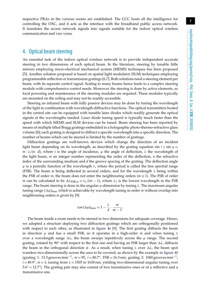
4. Optical beam steeringAn essential task of the indoor optical wireless network is to provide independent accuratesteering in two dimensions of each optical beam. In the literature, steering by tunable littlemirrors employing micro-electrical mechanical system (MEMS) techniques has been proposed[5]. Another solution proposed is based on spatial light modulator (SLM) techniques employingprogrammable reflection or transmission gratings [6,7]. Both solutions need a steering element perbeam, with its separate control signal. Scaling to many beams hence leads to a complex steeringmodule with comprehensive control needs. Moreover, the steering is done by active elements, solocal powering and maintenance of the steering modules are required. These modules typicallyare mounted on the ceiling and may not be readily accessible.
Steering an infrared beam with fully passive devices may be done by tuning the wavelengthof the light in combination with wavelength-diffractive functions. The optical transmitters hostedin the central site can be equipped with tunable laser diodes which readily generate the opticalsignals at the wavelengths needed. Laser diode tuning speed is typically much faster than thespeed with which MEMS and SLM devices can be tuned. Beam steering has been reported bymeans of multiple tilted Bragg gratings embedded in a holographic photo-thermo-refractive glassvolume [8]; each grating is designed to diffract a specific wavelength into a specific direction. Thenumber of beams which can be steered is limited by the number of gratings.
Diffraction gratings are well-known devices which change the direction of an incidentlight beam depending on its wavelength, as described by the grating equation sin i + sin ϕ =m · λ/(n · d), where i is the angle of incidence, ϕ the angle of deflection, λ the wavelength ofthe light beam, m an integer number representing the order of the deflection, n the refractiveindex of the surrounding medium and d the groove spacing of the grating. The deflection angleϕ is a periodic function of the wavelength λ, where the period is called the free spectral range(FSR). The beam is being deflected in several orders, and for the wavelength λ being withinthe FSR of order m, the beam does not enter the neighbouring orders (m ± 1). The FSR of orderm can be calculated to be ΔλFSR,m = λ1/(m − 1), where λ1 is the lowest wavelength in the FSRrange. The beam steering is done in the angular ϕ-dimension by tuning λ. The maximum angulartuning range (�ϕ)max which is achievable by wavelength tuning in order m without overlap intoneighbouring orders is given by [9]
cos (Δϕ)max = 1 − λ
d· m
m − 1.
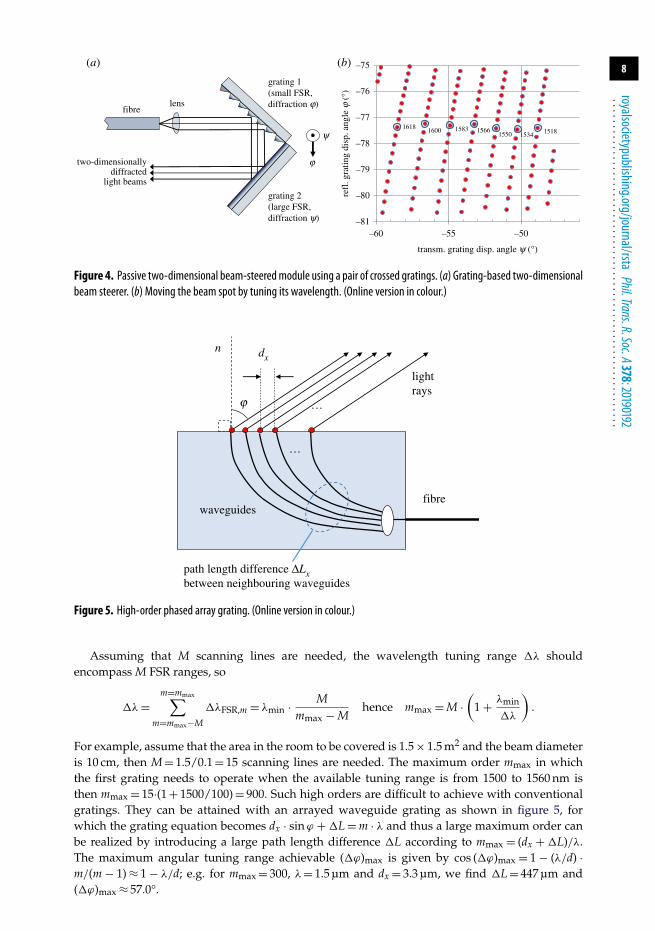
The beam inside a room needs to be steered in two dimensions for adequate coverage. Hence,we adopted a structure deploying two diffraction gratings which are orthogonally positionedwith respect to each other, as illustrated in figure 4a [9]. The first grating diffracts the beamin direction ϕ and has a small FSR, so it operates in a high-order m and when tuning λ
over a wavelength range �λ, the beam sweeps repetitively across the ϕ range. The secondgrating, rotated by 90° with respect to the first one and having an FSR larger than �λ, diffractsthe beam in the orthogonal direction ψ . As a result, when tuning λ over �λ, the beam spotwanders two-dimensionally across the area to be covered, as shown by the example in figure 4b(grating 1: 13.3 grooves mm−1, m = 95, i = 80.7°, FSR = 16.3 nm; grating 2: 1000 grooves mm−1,i = 49.9°, m = 1; tuning from λ= 1505 to 1630 nm, yielding two-dimensional angular tuning over5.6° × 12.7°). The grating pair may also consist of two transmissive ones or of a reflective and atransmissive one.
8
royalsocietypublishing.org/journal/rstaPhil.Trans.R.Soc.A378:20190192
...............................................................
grating 1(small FSR, diffraction j)
grating 2(large FSR,diffraction y)
fibrelens
y
jtwo-dimensionallydiffracted
light beams
–81
–80
–79
–78
–77
–76
–75
–60 –55 –50
refl
. gra
ting
disp
. ang
le j
(°)
transm. grating disp. angle y (°)
1518153415501566158316001618
(a) (b)
Figure 4. Passive two-dimensional beam-steeredmodule using a pair of crossed gratings. (a) Grating-based two-dimensionalbeam steerer. (b) Moving the beam spot by tuning its wavelength. (Online version in colour.)
fibre
path length difference DLxbetween neighbouring waveguides
j
n
lightrays
…
dx
waveguides
…
Figure 5. High-order phased array grating. (Online version in colour.)
Assuming that M scanning lines are needed, the wavelength tuning range �λ shouldencompass M FSR ranges, so
Δλ=m=mmax∑
m=mmax−M
ΔλFSR,m = λmin · Mmmax − M
hence mmax = M ·(
1 + λmin
Δλ
).
For example, assume that the area in the room to be covered is 1.5 × 1.5 m2 and the beam diameteris 10 cm, then M = 1.5/0.1 = 15 scanning lines are needed. The maximum order mmax in whichthe first grating needs to operate when the available tuning range is from 1500 to 1560 nm isthen mmax = 15·(1 + 1500/100) = 900. Such high orders are difficult to achieve with conventionalgratings. They can be attained with an arrayed waveguide grating as shown in figure 5, forwhich the grating equation becomes dx · sinϕ + ΔL = m · λ and thus a large maximum order canbe realized by introducing a large path length difference �L according to mmax = (dx + ΔL)/λ.The maximum angular tuning range achievable (�ϕ)max is given by cos (Δϕ)max = 1 − (λ/d) ·m/(m − 1) ≈ 1 − λ/d; e.g. for mmax = 300, λ= 1.5 µm and dx = 3.3 µm, we find �L = 447 µm and(�ϕ)max ≈ 57.0°.
9
royalsocietypublishing.org/journal/rstaPhil.Trans.R.Soc.A378:20190192
...............................................................
reflection grating13.3 g m–1
transmission grating1000 g m–1
mirror
lens coll.
1 m
lens coll.
tun. laser
RT osc. + BERT
AWG ext. mod.
mirror
pol. contr.
receiver
mirror
Figure 6. System experiment: two-dimensional beam steering with reflection and transmission grating, transferring30 Gbit s−1 per beam. (Online version in colour.)
In [10], a silicon integrated 1 × 4 phased array is reported which achieves a steering range ofup to 30°. Its limited amount of only four edge-emitting couplers yielded a large beam divergenceand hence limited reach (up to 1.4 m at 12.5 Gbit s−1).
Also a virtually imaged phased array (VIPA) [11], based on multiple beam interference ina parallel plate, can achieve very high orders of interference m and is well suited as a smallFSR diffractive element [12]; its angular range of operation, however, is only a few degrees.Also photonic integrated circuit solutions for passive two-dimensional beam steering have beenproposed using an array of grating couplers fed by arrayed waveguides in silicon-on-insulatortechnology [13]; losses were relatively high (8.9–10 dB) and the beam was relatively wide (4°).
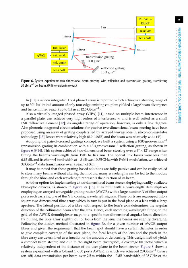
Adopting the pair-of-crossed gratings concept, we built a system using a 1000 grooves mm−1
transmission grating in combination with a 13.3 grooves mm−1 reflection grating, as shown infigure 6 [9,14]. This system achieved two-dimensional beam steering over a 6° × 12° range whentuning the beam’s wavelength from 1505 to 1630 nm. The optical link losses were less than6.15 dB, and its channel bandwidth at −3 dB was 10.35 GHz; with PAM4-modulation, we achieved32 Gbit s−1 data transmission over a reach of 3 m.
It may be noted that these grating-based solutions are fully passive and can be easily scaledto steer many beams without altering the module: many wavelengths can be fed to the modulethrough the fibre, and each wavelength represents the direction of its beam.
Another option for implementing a two-dimensional beam steerer, deploying readily availablefibre-optic devices, is shown in figure 7a [15]. It is built with a wavelength demultiplexeremploying an arrayed waveguide grating router (AWGR) with a large number N of fibre outputports each carrying one of the N incoming wavelength signals. These ports are regrouped into asquare two-dimensional fibre array, which in turn is put in the focal plane of a lens with a largeaperture. The lateral position of a fibre with respect to the lens’s axis determines the angulardirection of the collimated beam after the lens. Hence, each incoming wavelength fitting on thegrid of the AWGR demultiplexer maps to a specific two-dimensional angular beam direction.By putting the fibre array slightly out of focus from the lens, the beams are slightly diverging.Following the design method illustrated in figure 7b, for a given number of AWGR outputfibres and given the requirement that the beam spot should have a certain diameter in orderto give complete coverage of the user plane, the focal length of the lens and the pitch in thefibre array are determined as a function of the amount of defocusing. This design method yieldsa compact beam steerer, and due to the slight beam divergence, a coverage fill factor which isrelatively independent of the distance of the user plane to the beam steerer. Figure 8 shows asystem experiment with a C-band 1 × 80 ports AWGR, in which we achieved 20 Gbit s−1 binary(on–off) data transmission per beam over 2.5 m within the −3 dB bandwidth of 35 GHz of the

10
royalsocietypublishing.org/journal/rstaPhil.Trans.R.Soc.A378:20190192
...............................................................
lens
beamsl1, l2,..., lN
2D fibrearray
M × M
AWGR1 × N
ly
1D-to-2Dinterposer
inputfibre
lN
lens
F
b
f f
v
F
y2
AWGRfibres
x
D1
image plane
lens axis
D2
yc1Dyc
L
y01
l1 lx
Dy
a
(a) (b)
Figure 7. Passive two-dimensional beam steerer using an AWGR and fibre array. (a) Two-dimensional beam steerer. (b) Designof AWGR-based beam steerer. (Online version in colour.)
6 mm
f1 = 200 mm f2 = 20 mm
6 cm
l1 = 1529.100 nm
l2l3l4l5l6l7l8l9
d = 2.5m
AW
GR
9×9 fibrearray
lens
tun. LD1525 –
1580 nm
MZM
PRBS
EDFA
VOA
APD
MMF
TIA
BERtester
fibrecoll.
mid-IRfilter
Rxoptics
v= (1 – p) . f
Figure 8. System experiment: two-dimensional beam-steering employing AWGR and 9× 9 fibre array, transferring20 Gbit s−1 per beam. (Online version in colour.)
Table 2. Comparison of beam-steering technologies.
technologyscalability ofnumber of beams FoV coverage steering speed
active/passivemodule references
MEMSmirrors low 20°× 20° low active [5]. . . . . . . . . . . . . . . . . . . . . . . . . . . . . . . . . . . . . . . . . . . . . . . . . . . . . . . . . . . . . . . . . . . . . . . . . . . . . . . . . . . . . . . . . . . . . . . . . . . . . . . . . . . . . . . . . . . . . . . . . . . . . . . . . . . . . . . . . . . . . . . . . . . . . . . . . . . . . . . . . . . . . . . . . . . . . . . . . . . . . . . . . . . . . . . . . . . . . . . . . .
SLM low 3°× 3°a medium active [6,7]. . . . . . . . . . . . . . . . . . . . . . . . . . . . . . . . . . . . . . . . . . . . . . . . . . . . . . . . . . . . . . . . . . . . . . . . . . . . . . . . . . . . . . . . . . . . . . . . . . . . . . . . . . . . . . . . . . . . . . . . . . . . . . . . . . . . . . . . . . . . . . . . . . . . . . . . . . . . . . . . . . . . . . . . . . . . . . . . . . . . . . . . . . . . . . . . . . . . . . . . . .
two-dimensional grating high 6°× 12° high passive [9,14]. . . . . . . . . . . . . . . . . . . . . . . . . . . . . . . . . . . . . . . . . . . . . . . . . . . . . . . . . . . . . . . . . . . . . . . . . . . . . . . . . . . . . . . . . . . . . . . . . . . . . . . . . . . . . . . . . . . . . . . . . . . . . . . . . . . . . . . . . . . . . . . . . . . . . . . . . . . . . . . . . . . . . . . . . . . . . . . . . . . . . . . . . . . . . . . . . . . . . . . . . .
AWGR+ 2D fibre array medium 17°× 17° high passive [15,16]. . . . . . . . . . . . . . . . . . . . . . . . . . . . . . . . . . . . . . . . . . . . . . . . . . . . . . . . . . . . . . . . . . . . . . . . . . . . . . . . . . . . . . . . . . . . . . . . . . . . . . . . . . . . . . . . . . . . . . . . . . . . . . . . . . . . . . . . . . . . . . . . . . . . . . . . . . . . . . . . . . . . . . . . . . . . . . . . . . . . . . . . . . . . . . . . . . . . . . . . . .a18°with lens-based angle magnifier.
AWGR’s ports, with beam steering over a two-dimensional angular range of 17° × 17° whentuning over the C-band (1530–1565 nm). The aggregate system’s wireless capacity is huge, namely80 × 20 Gbit s−1 = 1.6 Tbit s−1. With the same AWGR, and PAM-4 modulation aided by digitalsignal processing for equalization, we achieved even 112 Gbit s−1 per beam, implying a potentialaggregate system capacity of 80 × 112 Gbit s−1 = 8.96 Tbit s−1 [16].
In table 2, the beam-steering technologies are compared qualitatively.When using MEMS-based mirrors or an SLM, the scalability towards many beams is limited
as each beam needs a separate steering element. The field-of-view for covering the user area isrelatively large when using MEMS mirrors and small when using an SLM (but can be increasedwith an angular magnifier, at the expense of narrowing the beam). Both for the MEMS-based andthe SLM-based steering, active electronic control at the steering module is needed, which requires

11
royalsocietypublishing.org/journal/rstaPhil.Trans.R.Soc.A378:20190192
...............................................................
a separate control line, and facilitates steering of the beam at slow/medium speed (in the orderof several milliseconds).
When using the diffractive two-dimensional grating-based concept, by remotely tuning thewavelength, continuous steering of a beam is feasible in one direction and stepwise steering inthe orthogonal direction. The number of beams is limited only by the resolving power of thegratings, which can be high. When using the AWGR + 2D fibre array, by remotely tuning thewavelength, the beam is steered stepwise in both the directions. The number of beams is limitedby the number of output ports of the AWGR, which can be in the order of 100. The beam-steeringspeed is dictated by the wavelength tuning speed of the laser diode. This tuning time may beonly a few nanoseconds for the laser diode itself; the tuning control electronics may increase thatto a few microseconds. The modules according to the two-dimensional grating concept as wellas the AWGR + 2D fibre array concept are both passive, so do not require local powering normaintenance. Their beam-steering control is done by tuning the wavelength of a remote laserdiode and does not need a separate control line (as the wavelength also carries the data signal).
Given their favourable fast steering speed, easy scaling and passive maintenance-free nature,in our research we have preferred the wavelength-tuned diffractive beam-steering techniquesusing two-dimensional gratings or an AWGR + 2D fibre array. Moreover, the latter one is notimpacted by polarization state fluctuations in the optical input signal (these may yield signalintensity fluctuations in the two-dimensional grating concept).
5. Free-space optical receiverNext to the beam-steered optical transmitter, the receiver catching the optical beam at the userside is an essential part of a high-speed optical wireless link. This receiver should acquire asmuch power as possible from the optical signal as well as be able to process high data rate signals,while also being small, consuming little power (as it is to be fed from the wireless user device,which typically is battery-operated) and low cost. In order to minimize the alignment effortswith respect to the transmitted beam, it should have a wide open aperture as well as a largefield-of-view (FoV). The physics law of conservation of étendue (https://en.wikipedia.org/wiki/Etendue) (also known as the A·Ω product, i.e. the product of entrance aperture A and solid angleΩ of the accepted cone of light), however, limits what optical measures such as lenses or mirrorscan do to extend both the aperture and the FoV. Compound parabolic concentrator mirrors havebeen used to expand the aperture at the cost of a reduced FoV (https://en.wikipedia.org/wiki/Nonimaging_optics). A slab antenna structure with large receiving aperture has been proposedwhich uses fluorescent material in the slab waveguide to convert incoming light to a longerwavelength which is subsequently constrained inside the waveguide by internal reflections andguided to a photodetector [17]. It thus breaks the étendue constraint and achieved a gain of 50×with respect to an étendue-preserving concentrator with the same FoV. Its dimensions so far limitits speed of operation.
Alternatively, the receiver may use a relatively small aperture which is actively scanning alarger FoV to find the incoming beam. This approach can only be applied when the transmitterhas already found the user’s device and has successfully steered a beam to it. By deploying anSLM the concept has been explored in [18]. We achieved an FoV’s half-angle of 18°, and receptionof 40 Gbit s−1 in on–off keying format over 0.5 m free-space reach.
At the cost of increased circuit complexity at the electronic side, the receiving aperture can beincreased by deploying an array of photodiodes. Each photodiode is followed by a low-noiseelectrical amplifier, where the outputs of these amplifiers are subsequently combined. Theseamplifiers also need to have closely matched phase characteristics in order to avoid destructivesignal interference. By applying a lens system on top, each of the diodes can look into a differentdirection, thus extending the field-of-view. Such a so-called angle diversity receiver was reportedin [19] featuring 7 InGaAs MSM photodiodes of 50 µm, followed by integrated CMOS amplifiers;it achieved a −3 dB bandwidth of 3.7 GHz.
12
royalsocietypublishing.org/journal/rstaPhil.Trans.R.Soc.A378:20190192
...............................................................
UTC photodiodesurface gratingcoupler
integrated OWC receiver
grating 10 × 10 mm2
5 mmG
S
G
UTC-PD
p-contact
open
Figure 9. Cascaded aperture optical receiver. (Online version in colour.)
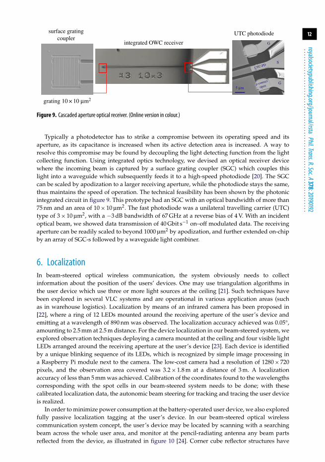
Typically a photodetector has to strike a compromise between its operating speed and itsaperture, as its capacitance is increased when its active detection area is increased. A way toresolve this compromise may be found by decoupling the light detecting function from the lightcollecting function. Using integrated optics technology, we devised an optical receiver devicewhere the incoming beam is captured by a surface grating coupler (SGC) which couples thislight into a waveguide which subsequently feeds it to a high-speed photodiode [20]. The SGCcan be scaled by apodization to a larger receiving aperture, while the photodiode stays the same,thus maintains the speed of operation. The technical feasibility has been shown by the photonicintegrated circuit in figure 9. This prototype had an SGC with an optical bandwidth of more than75 nm and an area of 10 × 10 µm2. The fast photodiode was a unilateral travelling carrier (UTC)type of 3 × 10 µm2, with a −3 dB bandwidth of 67 GHz at a reverse bias of 4 V. With an incidentoptical beam, we showed data transmission of 40 Gbit s−1 on–off modulated data. The receivingaperture can be readily scaled to beyond 1000 µm2 by apodization, and further extended on-chipby an array of SGC-s followed by a waveguide light combiner.
6. LocalizationIn beam-steered optical wireless communication, the system obviously needs to collectinformation about the position of the users’ devices. One may use triangulation algorithms inthe user device which use three or more light sources at the ceiling [21]. Such techniques havebeen explored in several VLC systems and are operational in various application areas (suchas in warehouse logistics). Localization by means of an infrared camera has been proposed in[22], where a ring of 12 LEDs mounted around the receiving aperture of the user’s device andemitting at a wavelength of 890 nm was observed. The localization accuracy achieved was 0.05°,amounting to 2.5 mm at 2.5 m distance. For the device localization in our beam-steered system, weexplored observation techniques deploying a camera mounted at the ceiling and four visible lightLEDs arranged around the receiving aperture at the user’s device [23]. Each device is identifiedby a unique blinking sequence of its LEDs, which is recognized by simple image processing ina Raspberry Pi module next to the camera. The low-cost camera had a resolution of 1280 × 720pixels, and the observation area covered was 3.2 × 1.8 m at a distance of 3 m. A localizationaccuracy of less than 5 mm was achieved. Calibration of the coordinates found to the wavelengthscorresponding with the spot cells in our beam-steered system needs to be done; with thesecalibrated localization data, the autonomic beam steering for tracking and tracing the user deviceis realized.
In order to minimize power consumption at the battery-operated user device, we also exploredfully passive localization tagging at the user’s device. In our beam-steered optical wirelesscommunication system concept, the user’s device may be located by scanning with a searchingbeam across the whole user area, and monitor at the pencil-radiating antenna any beam partsreflected from the device, as illustrated in figure 10 [24]. Corner cube reflector structures have

13
royalsocietypublishing.org/journal/rstaPhil.Trans.R.Soc.A378:20190192
...............................................................
SFP+tunable transceiver
SFP+tunabletransceiver
centralsite
RxTxTx Rx
10 GbEvideo
server 2
10 GbEvideo
Server 1
EDFA
localizationprocessor
user
freespace2.5 mPRA
receiver
PIN+TIA
CCdetectorpower meter
RS-PI
C
L
AWGR lens
monitortunable XFPtransceiver
PIN TIA
l-converter
lensfibre
Figure 10. System experiment featuring fully passive device localization. (Online version in colour.)
been used, which reflect a part of the incident beam back into exactly the same direction as it camefrom. This reflected beam gets a slight lateral offset by the corner cube, which is proportional tothe size of the corner cube. To minimize this offset while also reflecting enough light to be detectedadequately at the PRA, we deployed an array of passive miniature corner cubes embeddedin a foil (as commonly used for, e.g. road signage). Circular foils of 4 cm diameter were used,with a central hole of 3 cm hosting the receiver’s downstream beam detector. The central holereduced the returned power by about 3.2 dB. With a beam power of 10 mW and a beam diameterof typically 10 cm, the localization monitoring photodetector unit next to the PRA detected areturned power of −31 dBm, which was sufficient for localizing the device well within the cellresolution. We implemented this passive localization method in our laboratory demonstrator andshowed its feasibility while carrying two independent video streams embedded in 10 Gbit s−1
Ethernet links ( figure 10). The scanning time of the whole area is presently limited to about 15 s inour set-up, predominantly by software processes. Intrinsically, the localization time is constrainedby the time needed to tune the wavelength of a laser diode over the full range, which can be donewithin a few milliseconds. However, the additional steps in the scanning process are stepwisetuning to each cell consecutively, deciding whether there is retro-reflected power from that cellexceeding the background noise level, and then moving to the next cell. Per cell this takes 115 ms,of which only a few ms are consumed by the intrinsic tuning time of the laser diode, and themajority is taken by the Labview software running in the laptop controller, the Arduino boardwhich controls the laser tuning, and the read-out time of the localization power meter. Scanningthe 128 cells thus takes about 15 s; more efficient algorithms are being investigated to reduce thistime remarkably, preferably implemented in embedded software. Figure 11 illustrates how inthe wavelength scanning process the locations of two user devices, each equipped with a 4 cmdiameter corner cube reflector foil, are found. The two peaks visible in figure 11a clearly indicatethe wavelengths which correspond to the positions of the two devices indicated in figure 11b,respectively.
Next to being fully passive at the user side, so not drawing any power of its battery, this cornercube reflector method also offers the advantage that it is self-calibrating the location data to thebeam-steering parameters: while wavelength scanning the area and monitoring the reflectionsat the same time, the system directly finds which wavelengths needed for the beam steering domap to the respective locations of the user devices and can store these wavelength values for thebeam-steering system controller.

14
royalsocietypublishing.org/journal/rstaPhil.Trans.R.Soc.A378:20190192
...............................................................
–44
1536
.59
1539
.75
1542
.92
1546
.1
1549
.3
1552
.5
1555
.73
1558
.96
1562
.21
1565
.47
–42
–40
–38
–36
–34
–32
–30
dete
cted
pow
er (
dBm
)
wavelength (nm)
noise floor
scanned areawith device positions
(a) (b)
Figure 11. Device localization by monitoring signal power reflected from the user devices. (a) Reflected power versuswavelength. (b) Position of the two user devices in the cell-patterned user area. (Online version in colour.)
CCC
1500 nm
PC–1600 nm
MZM driver OC1 OC2
IF
RF
free spaceD = 2.5 m
f2 = 5 mm
d 1=
50 m
m
d 2=
8.3
cm
f1 = 50 mm
MMF
fibrefocuser
LO
RFIF
LO––2
SMF2 km
steeringlens
localizationcontrol
f
tunablelaser
bit-patterngenerator
MZM EDFA OXC PRA2
PRA-Tx
AWG
Rx unit
Tx unit
PRA-Rx
PRA1
user-1
PRA3
PRA4
PD+TIA
Bit-errortester
integratedoptical Tx
downlink PIN TIA bit-errortester
Amp
mixer
Rx Horn typeantenna
60 GHzTx antennas
Amp
Hybrid Tee 60 GHz signalgenerator
Elec-Mech2D posioner
bit-patterngeneratoruplink60 GHz signal
generator
l1 1529 nm
l811569.8 nm
l2l3l4l5l6l7l8l9
Figure 12. Hybrid wireless communication system featuring downstream two-dimensional beam-steered optical wirelesscommunication and upstream 60 GHz based radio link. (Online version in colour.)
7. Bidirectional wireless communication systemsMost broadband services, such as downloading video streams and large files from the internet, arehighly asymmetric in nature, they require much more downstream link capacity than upstream.Beam-steered optical wireless communication is well suited for such broadband asymmetrictraffic, particularly in a hybrid system combination where radio links are used for upstream.The radio upstream link does not necessarily require a LoS path and hence can advantageouslyserve for initiating a request for an optical wireless connection and for acknowledging when theconnection has been established. And it also can provide the return channel, albeit at a somewhatlower capacity than the downstream optical channel.
A hybrid bidirectional system we have built in our laboratories is shown in figure 12 [25]. Indownstream, it uses the 1 × 80 ports AWGR and an f = 40 cm condenser lens, with which beamsof 8.3 cm diameter over a 2.5 m reach transferred 35 Gbit s−1 binary modulated data streams. Inupstream, two horn antennas with 30 dBi gain were used at the user device side and a 16 dBiantenna at the PRA side, which transferred 5 Gbit s−1 amplitude-shift-keyed modulated 60 GHzradio beams. For setting up the connection, the upstream two horn antennas at the user wereelectro-mechanically directed towards the horn antenna at the PRA.
8. Laboratory system demonstratorAn elaborated set-up was built in our laboratories as shown in figure 13, which demonstratesthe downstream real-time transfer of two high-definition video streams, each embedded in a
15
royalsocietypublishing.org/journal/rstaPhil.Trans.R.Soc.A378:20190192
...............................................................
fibres
PRA
opticalreceivers
CCC with 2tunabletransmitters
PRA
videossent
videosreceived
controllaptop
7 cells captured withIR camera at 2.5 m
localization detector
MEMS switch
Figure 13. Laboratory demonstrator. (Online version in colour.)
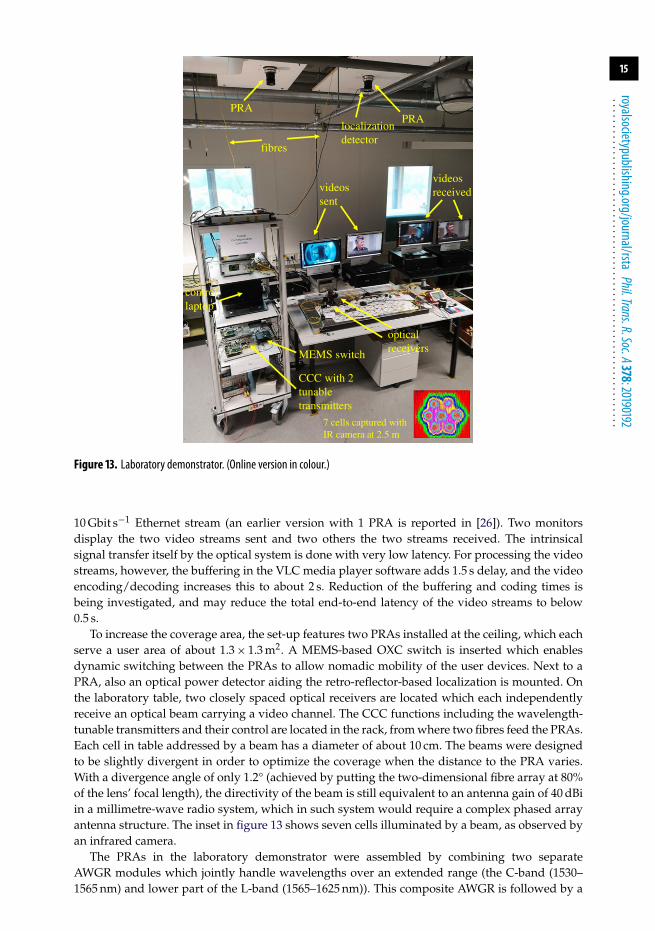
10 Gbit s−1 Ethernet stream (an earlier version with 1 PRA is reported in [26]). Two monitorsdisplay the two video streams sent and two others the two streams received. The intrinsicalsignal transfer itself by the optical system is done with very low latency. For processing the videostreams, however, the buffering in the VLC media player software adds 1.5 s delay, and the videoencoding/decoding increases this to about 2 s. Reduction of the buffering and coding times isbeing investigated, and may reduce the total end-to-end latency of the video streams to below0.5 s.
To increase the coverage area, the set-up features two PRAs installed at the ceiling, which eachserve a user area of about 1.3 × 1.3 m2. A MEMS-based OXC switch is inserted which enablesdynamic switching between the PRAs to allow nomadic mobility of the user devices. Next to aPRA, also an optical power detector aiding the retro-reflector-based localization is mounted. Onthe laboratory table, two closely spaced optical receivers are located which each independentlyreceive an optical beam carrying a video channel. The CCC functions including the wavelength-tunable transmitters and their control are located in the rack, from where two fibres feed the PRAs.Each cell in table addressed by a beam has a diameter of about 10 cm. The beams were designedto be slightly divergent in order to optimize the coverage when the distance to the PRA varies.With a divergence angle of only 1.2° (achieved by putting the two-dimensional fibre array at 80%of the lens’ focal length), the directivity of the beam is still equivalent to an antenna gain of 40 dBiin a millimetre-wave radio system, which in such system would require a complex phased arrayantenna structure. The inset in figure 13 shows seven cells illuminated by a beam, as observed byan infrared camera.
The PRAs in the laboratory demonstrator were assembled by combining two separateAWGR modules which jointly handle wavelengths over an extended range (the C-band (1530–1565 nm) and lower part of the L-band (1565–1625 nm)). This composite AWGR is followed by a
16
royalsocietypublishing.org/journal/rstaPhil.Trans.R.Soc.A378:20190192
...............................................................
MZMdataDS
tun. LD
RxdataUS
lens coll.grating
1 m
coupler RxdataDS
SOA
MZMdataUS
mirror
circulator
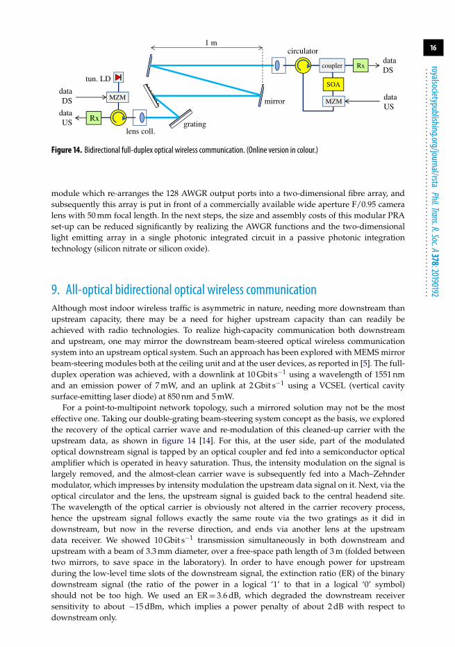
Figure 14. Bidirectional full-duplex optical wireless communication. (Online version in colour.)
module which re-arranges the 128 AWGR output ports into a two-dimensional fibre array, andsubsequently this array is put in front of a commercially available wide aperture F/0.95 cameralens with 50 mm focal length. In the next steps, the size and assembly costs of this modular PRAset-up can be reduced significantly by realizing the AWGR functions and the two-dimensionallight emitting array in a single photonic integrated circuit in a passive photonic integrationtechnology (silicon nitrate or silicon oxide).
9. All-optical bidirectional optical wireless communicationAlthough most indoor wireless traffic is asymmetric in nature, needing more downstream thanupstream capacity, there may be a need for higher upstream capacity than can readily beachieved with radio technologies. To realize high-capacity communication both downstreamand upstream, one may mirror the downstream beam-steered optical wireless communicationsystem into an upstream optical system. Such an approach has been explored with MEMS mirrorbeam-steering modules both at the ceiling unit and at the user devices, as reported in [5]. The full-duplex operation was achieved, with a downlink at 10 Gbit s−1 using a wavelength of 1551 nmand an emission power of 7 mW, and an uplink at 2 Gbit s−1 using a VCSEL (vertical cavitysurface-emitting laser diode) at 850 nm and 5 mW.
For a point-to-multipoint network topology, such a mirrored solution may not be the mosteffective one. Taking our double-grating beam-steering system concept as the basis, we exploredthe recovery of the optical carrier wave and re-modulation of this cleaned-up carrier with theupstream data, as shown in figure 14 [14]. For this, at the user side, part of the modulatedoptical downstream signal is tapped by an optical coupler and fed into a semiconductor opticalamplifier which is operated in heavy saturation. Thus, the intensity modulation on the signal islargely removed, and the almost-clean carrier wave is subsequently fed into a Mach–Zehndermodulator, which impresses by intensity modulation the upstream data signal on it. Next, via theoptical circulator and the lens, the upstream signal is guided back to the central headend site.The wavelength of the optical carrier is obviously not altered in the carrier recovery process,hence the upstream signal follows exactly the same route via the two gratings as it did indownstream, but now in the reverse direction, and ends via another lens at the upstreamdata receiver. We showed 10 Gbit s−1 transmission simultaneously in both downstream andupstream with a beam of 3.3 mm diameter, over a free-space path length of 3 m (folded betweentwo mirrors, to save space in the laboratory). In order to have enough power for upstreamduring the low-level time slots of the downstream signal, the extinction ratio (ER) of the binarydownstream signal (the ratio of the power in a logical ‘1’ to that in a logical ‘0’ symbol)should not be too high. We used an ER = 3.6 dB, which degraded the downstream receiversensitivity to about −15 dBm, which implies a power penalty of about 2 dB with respect todownstream only.
17
royalsocietypublishing.org/journal/rstaPhil.Trans.R.Soc.A378:20190192
...............................................................
10. Concluding remarksOptical wireless communication techniques offer powerful solutions to resolve the imminentcongestion in radio-based communication networks, in particular in local area wireless networks.By deploying steerable narrow infrared optical beams which address each user deviceindividually, it can provide links with ultra-high capacity where and when needed, while alsooffering high privacy. Their small footprint enables the creation of a pico-cell per user deviceand thus creates a high degree of spatial multiplexing which boosts the total wireless system’sthroughput. As the beams deliver communication capacity on demand only to those places whereand when needed, the system achieves high efficiency in bringing the data signals to the users andthus can reduce remarkably the power consumption needed with respect to a radio-based mm-wave communication system. Moreover, as nothing travels faster than light in vacuum (and air), aminimum in latency is achieved which makes it also eminently suited for time-critical machine-to-machine interactions. Radio beams travel equally fast, but due to the lower bandwidths accessiblein a radio channel, extra processing time is needed for signal conditioning, which adds to the radiolink’s latency. By deploying two-dimensional-steered narrow infrared beams, we demonstratedcapacities up to 112 Gbit s−1 per beam and demonstrated live high-definition video streamingwith up to 128 beams in a hybrid optical wireless downstream and radio wireless upstreamsystem. By means of photonic integration, the size and costs of the two-dimensional beam steereras well as of the optical receiver circuitry at the user device can be reduced significantly; researchon such integration steps is ongoing. A next goal is all-optical wireless communication in bothdirections. Using optical carrier recovery at the user side, all-optical full-duplex bidirectionalwireless communication can be established; so far, we have realized this at 10 Gbit s−1 in bothdirections.
Optical wireless communication by means of narrow infrared beams can provide the ultimatecapabilities for delivering broadband services wirelessly in human-to-machine and machine-to-machine communications, e.g. in terms of high capacity, low power consumption, high privacyand low latency. It is not foreseen to fully replace radio-based wireless communication, amongothers because it needs line-of-sight. But it can off-load high-speed traffic loads from radio-basednetworks and thus give these the room necessary to handle the booming amounts of low-speedintermittent traffic as, e.g. generated by the emerging myriad of small internet-of-things devices.
Data accessibility. This article has no additional data.Authors’ contributions. K.M. and F.H. contributed to laboratory experiments and setting up the demonstrator.Z.C. contributed on the integrated optical wireless receiver. N.Q.P. contributed on the camera-based devicelocalization. E.T. contributed in supervising the junior researchers and in system discussions.Competing interests. We declare we have no competing interestsFunding. The European Research Council (ERC) is gratefully acknowledged for funding this research in theAdvanced Investigator Grant project BROWSE—Beam-steered Reconfigurable Optical-Wireless System forEnergy-efficient communication, and the follow-up Proof-of-Concept project BROWSE+. KPN is gratefullyacknowledged for funding the work of N.Q.P.
References1. Haas H, Yin L, Wang Y, Chen C. 2016 What is LiFi? J. Lightw. Technol. 34, 1533–1544.
(doi:10.1109/JLT.2015.2510021)2. O’Brien DC. 2016 Optical wireless communications: current status and future prospects. In
Proc. IEEE Summ. Top., Newport Beach, CA, 11–13 July. Piscataway, NJ: IEEE Photonics Society.3. Koonen AMJ. 2018. Indoor optical wireless systems: technology, trends, and applications. J.
Lightw. Technol. 36, 1459–1467. (doi:10.1109/JLT.2017.2787614)4. Koonen AMJ. 2018 Optical wireless systems: technology, trends and applications. In
Proc. Int. Conf. IEEE Photon. Webinar, Feb. 2018. See https://www.photonicssociety.org/educationcareers/webinars/optical-wireless-communication-webinar.
5. Wang K, Nirmalathas A, Lim C, Alameh K, Skafidas E. 2016 Full-duplex gigabit indoor opticalwireless communication system with CAP modulation. IEEE Photon. Technol. Lett. 28, 790–793.(doi:10.1109/LPT.2015.2514102)

18
royalsocietypublishing.org/journal/rstaPhil.Trans.R.Soc.A378:20190192
...............................................................
6. Gomez A, Shi K, Quintana C, Sato M, Faulkner G, Thomsen BC, O’Brien DC. 2015 Beyond100-Gb/s indoor wide field-of-view optical wireless communications. Phot. Technol. Lett. 27,367–370. (doi:10.1109/LPT.2014.2374995)
7. Gomez A, Quintana C, Faulkner G, O’Brien DC. 2016 Point-to-multipoint holographicbeamsteering techniques for indoor optical wireless communications. In Proc. of SPIE 9772,paper no. 97720Q. Bellingham, WA: SPIE. (doi:10.1117/12.2213252)
8. Yaqoob Z, Arain MA, Riza NA. 2003 High-speed two-dimensional laser scanner basedon Bragg gratings stored in photothermorefractive glass. Appl. Opt. 42, 5251–5262.(doi:10.1364/AO.42.005251)
9. Koonen AMJ, Oh CW, Mekonnen KA, Cao Z, Tangdiongga E. 2016 Ultra-high capacity indooroptical wireless communication using 2d-steered pencil beams. J. Lightw. Technol. 34, 4802–4809. (doi:10.1109/JLT.2016.2574855)
10. Wang K, Yuan Z, Wong E, Alameh K, Li H, Sithamparanathan K, Skafidas E. 2019Experimental demonstration of indoor infrared optical wireless communications witha silicon photonic integrated circuit. J. Lightwave Technol. 37, 619–626. (doi:10.1109/JLT.2018.2889252)
11. Shirasaki M. 1996 Large angular dispersion by a virtually imaged phased array andits application to a wavelength demultiplexer. Opt. Lett. 21, 366–368. (doi:10.1364/OL.21.000366)
12. Chan T, Myslivets E, Ford JE. 2008 2-Dimensional beamsteering using dispersivedeflectors and wavelength tuning. Opt. Express 16, 14 617–14 628. (doi:10.1364/OE.16.014617)
13. Van Acoleyen K, Bogaerts W, Baets R. 2011 Two-dimensional dispersive off-chip beam scannerfabricated on silicon-on-insulator. Photonics Technol. Lett. 23, 1270–1272. (doi:10.1109/LPT.2011.2159785)
14. Oh CW. 2017 Free-space transmission with passive two-dimensional beam steering for indooroptical wireless networks. PhD thesis, Eindhoven University of Technology, The Netherlands.
15. Koonen AMJ, Gomez-Agis F, Huijskens FM, Mekonnen KA, Cao Z, Tangdiongga E. 2018High-capacity optical wireless communication using two-dimensional IR beam steering.J. Lightwave. Technol. 36, 4486–4493. (doi:10.1109/JLT.2018.2834374)
16. Gomez-Agis F, Van der Heide SP, Okonkwo CM, Tangdiongga E, Koonen AMJ. 2017112 Gbit/s transmission in a 2D beam steering AWG-based optical wireless communicationsystem. In Proc. ECOC2017, Göteborg, 17–21 September 2017, Paper Th.2.B.1. Piscataway, NJ:IEEE. (doi:10.1109/ECOC.2017.8346059)
17. Collins S, O’Brien DC, Watt A. 2014 High gain, wide field of view concentrator for opticalcommunications. Opt. Lett. 39, 1756–1759. (doi:10.1364/OL.39.001756)
18. Zhang X, Liu Y, Cao Z, Li F, Li Z, Ismaeel R, Brambilla G, Chen Y, Koonen AMJ. 2018 40 Gb/sindoor optical wireless system enabled by a cyclically arranged optical beamsteering receiver.Opt. Lett. 43, 723–726. (doi:10.1364/OL.43.000723)
19. Zeng J, Joyner V, Liao J, Deng S, Huang Z. 2009. A 5 Gb/s 7-channel current-mode imagingreceiver front-end for free-space optical MIMO. In Proc. IEEE MWSCAS 2009, Cancun, pp.148–151. Piscataway, NJ: IEEE. (doi:10.1109/MWSCAS.2009.5236130)
20. Cao Z, Shen L, Jiao Y, Zhao X, Koonen AMJ. 2017 200 Gbps OOK transmission over an indooroptical wireless link enabled by an integrated cascaded aperture optical receiver. In Proc.OFC2017, Los Angeles, CA, 19–23 March, post-deadline paper Th5A.6.
21. Do T-H, Yoo M. 2016 An in-depth survey of visible light communication based positioningsystems. Sensors 16, 678. (doi:10.3390/s16050678)
22. Gomez A, Shi K, Quintana C, Faulkner G, Thomsen BC, O’Brien DC. 2016 A50 Gb/s transparent indoor optical wireless communications link with an integratedlocalisation and tracking system. J. Lightwave Technol., 34, 2510–2517. (doi:10.1109/JLT.2016.2542158)
23. Pham NQ, Mekonnen KA, Tangdiongga E, Mefleh A, Koonen AMJ. 2019 Accurate indoorlocalisation for beam-steered OWC system using optical camera. In Proc. ECOC2019, Dublin,Ireland, 15–19 September, P45. London, UK: IET.
24. Koonen AMJ, Mekonnen KA, Huijskens FM, Tangdiongga E. 2019 Fully passive userlocalisation for beam steered high capacity optical wireless communication system. In Proc.ECOC2019, Dublin, Ireland, 15–19 September, Tu.3.C.4. London, UK: IET.

19
royalsocietypublishing.org/journal/rstaPhil.Trans.R.Soc.A378:20190192
...............................................................
25. Khalid AM, Baltus P, Dommele AR, Mekonnen KA, Cao Z, Oh CW, Matters MK,Koonen AMJ. 2017 Bi-directional 35-Gbit/s 2D beam steered optical wireless downlink and5-gbit/s localized 60-GHz communication uplink for hybrid indoor wireless systems. In Proc.OFC2017, Los Angeles, CA, 19–23 March, paper Th1E.6. Piscataway, NJ: IEEE.
26. Koonen AMJ, Gomez-Agis F, Sung J-Y, Cao Z, Mekonnen K, Huijskens F, Tangdiongga E.2018 Recent advances in optical technologies for creating ultra-high capacity wireless indoornetworks. In Proc. ACP2018, Hangzhou, 26–29 October 2018, paper S4E.2. Washington, DC: OSA.
Related Documents


