June, 2017 Microwave Review 35 Ultra-Compact LPF with Wide Stop-Band Prashant Kumar Singh, Anjini Kumar Tiwary Abstract – An ultra-compact, planar, wide stop-band and low cost low-pass filter (LPF) is proposed using microstrip stepped impedance hairpin resonator (SIHR). The wider stop-band is achieved by loading the SIHR with radial stub within the SIHR area, which provides compactness. Further widening of stop- band is achieved by introducing quarter wavelength transmission stub at 50 Ω line, to produce transmission zero at higher frequency. The proposed LPF is designed for 3 dB cut-off frequency of 3 GHz having wide stop-band up to 12 GHz with three transmission zeroes in stop-band at 4.3 GHz, 7.5 GHz and 11 GHz. The microstrip circuit size is only 10 mm × 7.5 mm. The simulation result and measured result shows good agreement, which validates the proposed design. Keywords – Low-pass filter (LPF), Stepped impedance hairpin resonator (SIHR), Radial stub, Microstrip filter. I. INTRODUCTION The recent trend of microwave and wireless system demands compact and high performance planar components. Microstrip low-pass filter (LPF) is one of the vital components in microwave and wireless system, which is used to suppress undesired harmonics. The conventional LPFs [1] suffer from gradual cut-off transition and narrow stop-band bandwidth. Various microstrip filter configurations [2-9] are developed to cope with these problems. The wider stop-band can be achieved by cascading multiple filter sections, which in turn increases the overall size of the filter. Compact structure and wider stop-band can also be achieved by using other methods like defected ground structure (DGS) [2-5] and electromagnetic band-gap (EBG) [6-7], while etched ground of DGS and periodic nature of EBG creates radiation problem. Several open circuited stubs are used to generate multiple transmission zeros in stop-band region to widen the stop-band [8], which cause the increased structural dimension. The compact LPFs are also designed using multiple Hilbert fractal lines [9] at the cost of poor stop-band response. The radiation problem can be resolved by using planar structure. The planar stepped impedance hairpin resonator (SIHR) or planar radial stub attracted many researchers due to their compactness and easier fabrication. Conventional SIHRs have the limitation of narrow stop-band bandwidth. The wider stop-band bandwidth is achieved by cascading or modifying SIHRs [10-15]. Due to the advantage of wide stop-band and Article history: Received June 30, 2016; Accepted June 01, 2017 Prashant Kumar Singh is with Department of Electronics and Communication Engineering, National Institute of Science & Technology, Berhampur, Orissa-761008, India, E-mail: [email protected] Anjini Kumar Tiwary is with Department of Electronics and Communication Engineering, Birla Institute of Technology, Mesra, Ranchi, 835215, Jharkhand, India, E-mail: [email protected] proper localization of zero-point impedance, radial stub is very good choice to extend the stop-band region [16]. The LPFs with wider stop-band is achieved by using radial stub [17-18]. In this paper, a new ultra-compact, planar, broad stop-band, low cost LPF is proposed. The ultra-compact LPF configuration with wide stop-band is achieved by inserting the radial stub within the area of SIHR, such that overall size of the filter remains same. Further extension of stop-band is achieved by inserting quarter wavelength resonator at 50 Ω line, such that overall size remains compact. The LPF is designed for 3 dB cut-off frequency of 3 GHz having wide stop-band from 3.6 GHz to 12 GHz with rejection level below 10 dB. The size of the filter is only 75 mm 2 . II. FILTER DESIGN A. Elliptic Function LPF The lumped element model of third order (n = 3) elliptic function low-pass filter (LPF) is shown in Fig. 1(a) and its microstrip stepped impedance hairpin resonator (SIHR) LPF configuration is shown in Fig. 1(b). For this the low-pass prototype values are selected as [1]: 0 4 1 3 2 2 1, 0.9471, 1.0173, 0.1205. Cps Ls Cg g g g g g g g g g The L-C element values of this LPF, for 3 GHz cut-off frequency ( c f ), can be calculated using the equations [1]: 0 1 2 s Ls c L Z g f in H, (1) 0 1 2 ps Cps c C g fZ in F , (2) 0 1 2 g Cg c C g fZ in F. (3) Here 0 50 Z is input/output terminal impedance. The calculated values of inductance ( s L ) and capacitances ( ps C and g C ) are given in Table 1. Advanced Design System (ADS2009) circuit simulator by Agilent Technologies is used for simulating lumped circuits. The simulated S-parameters response for the elliptic function LPF is shown in Fig. 2. The SIHR is composed of a transmission line having length l s and coupled lines with length l c . All microstrip filter configurations are designed on the low cost FR-4 glass epoxy substrate with dielectric constant (ε r ) of 4.4, thickness (h) 1.56 mm and loss tangent (tan δ) 0.016. The microstrip

Welcome message from author
This document is posted to help you gain knowledge. Please leave a comment to let me know what you think about it! Share it to your friends and learn new things together.
Transcript

June, 2017 Microwave Review
35
Ultra-Compact LPF with Wide Stop-Band
Prashant Kumar Singh, Anjini Kumar Tiwary
Abstract – An ultra-compact, planar, wide stop-band and low cost low-pass filter (LPF) is proposed using microstrip stepped impedance hairpin resonator (SIHR). The wider stop-band is achieved by loading the SIHR with radial stub within the SIHR area, which provides compactness. Further widening of stop-band is achieved by introducing quarter wavelength transmission stub at 50 Ω line, to produce transmission zero at higher frequency. The proposed LPF is designed for 3 dB cut-off frequency of 3 GHz having wide stop-band up to 12 GHz with three transmission zeroes in stop-band at 4.3 GHz, 7.5 GHz and 11 GHz. The microstrip circuit size is only 10 mm × 7.5 mm. The simulation result and measured result shows good agreement, which validates the proposed design.
Keywords – Low-pass filter (LPF), Stepped impedance hairpin resonator (SIHR), Radial stub, Microstrip filter.
I. INTRODUCTION
The recent trend of microwave and wireless system demands compact and high performance planar components. Microstrip low-pass filter (LPF) is one of the vital components in microwave and wireless system, which is used to suppress undesired harmonics. The conventional LPFs [1] suffer from gradual cut-off transition and narrow stop-band bandwidth. Various microstrip filter configurations [2-9] are developed to cope with these problems. The wider stop-band can be achieved by cascading multiple filter sections, which in turn increases the overall size of the filter. Compact structure and wider stop-band can also be achieved by using other methods like defected ground structure (DGS) [2-5] and electromagnetic band-gap (EBG) [6-7], while etched ground of DGS and periodic nature of EBG creates radiation problem. Several open circuited stubs are used to generate multiple transmission zeros in stop-band region to widen the stop-band [8], which cause the increased structural dimension. The compact LPFs are also designed using multiple Hilbert fractal lines [9] at the cost of poor stop-band response.
The radiation problem can be resolved by using planar structure. The planar stepped impedance hairpin resonator (SIHR) or planar radial stub attracted many researchers due to their compactness and easier fabrication. Conventional SIHRs have the limitation of narrow stop-band bandwidth. The wider stop-band bandwidth is achieved by cascading or modifying SIHRs [10-15]. Due to the advantage of wide stop-band and
Article history: Received June 30, 2016; Accepted June 01, 2017 Prashant Kumar Singh is with Department of Electronics and
Communication Engineering, National Institute of Science & Technology, Berhampur, Orissa-761008, India, E-mail: [email protected]
Anjini Kumar Tiwary is with Department of Electronics and Communication Engineering, Birla Institute of Technology, Mesra, Ranchi, 835215, Jharkhand, India, E-mail: [email protected]
proper localization of zero-point impedance, radial stub is very good choice to extend the stop-band region [16]. The LPFs with wider stop-band is achieved by using radial stub [17-18].
In this paper, a new ultra-compact, planar, broad stop-band, low cost LPF is proposed. The ultra-compact LPF configuration with wide stop-band is achieved by inserting the radial stub within the area of SIHR, such that overall size of the filter remains same. Further extension of stop-band is achieved by inserting quarter wavelength resonator at 50 Ω line, such that overall size remains compact. The LPF is designed for 3 dB cut-off frequency of 3 GHz having wide stop-band from 3.6 GHz to 12 GHz with rejection level below 10 dB. The size of the filter is only 75 mm2.
II. FILTER DESIGN
A. Elliptic Function LPF
The lumped element model of third order (n = 3) elliptic function low-pass filter (LPF) is shown in Fig. 1(a) and its microstrip stepped impedance hairpin resonator (SIHR) LPF configuration is shown in Fig. 1(b). For this the low-pass prototype values are selected as [1]:
0 4
1 3
2
2
1,
0.9471,
1.0173,
0.1205.
Cps
Ls
Cg
g g
g g g
g g
g g
The L-C element values of this LPF, for 3 GHz cut-off frequency ( cf ), can be calculated using the equations [1]:
01
2s Lsc
L Z gf
in H, (1)
0
1
2ps Cpsc
C gf Z
in F , (2)
0
1
2g Cgc
C gf Z
in F. (3)
Here 0 50Z is input/output terminal impedance. The
calculated values of inductance ( sL ) and capacitances ( psC
and gC ) are given in Table 1. Advanced Design System
(ADS2009) circuit simulator by Agilent Technologies is used for simulating lumped circuits. The simulated S-parameters response for the elliptic function LPF is shown in Fig. 2. The SIHR is composed of a transmission line having length ls and coupled lines with length lc. All microstrip filter configurations are designed on the low cost FR-4 glass epoxy substrate with dielectric constant (εr) of 4.4, thickness (h) 1.56 mm and loss tangent (tan δ) 0.016. The microstrip
Mikrotalasna revija Jun 2017
36
configurations are simulated using IE3D, full wave method of moments (MoM) based simulation software by Zeland. For microstrip SIHR realization, Zs (characteristic impedance of transmission line) is selected as Zs > (Z0e Z0o)
1/2 . Here Z0e and Z0o are even and odd-mode impedances of parallel coupled lines. In SIHR configuration, Zc is the characteristic impedance of microstrip line having width wc and length lc. The impedance of high and low impedance section are chosen as Zs = 111.5 Ω and Zc = 41.5 Ω corresponds to their respective widths are ws = 0.5 mm and wc = 4 mm, respectively. For the fixed value of g = 0.5 mm, even and odd-mode impedances can be calculated as Z0e = 36.5 Ω and Z0o = 28.4 Ω. By using the calculated L-C values from Table 1, the dimensional parameters of SIHR can be calculated from the given equations [11]:
sin( )
2s s s
sc
Z lL
f
in H, (4)
1 cos( )
2 sin( )s s
sc s s s
lC
f Z l
in F, (5)
0 0
0 04 cot( )e o
gc e o c c
Z ZC
f Z Z l
in F, (6)
0
1
2 cot( )pc e c c
Cf Z l
in F, (7)
(0.012 0.0039 ) ( )r c sC w w in pF, (8)
ps p sC C C C , (9)
1sin (2 / )c s s
ss
f L Zl
, (10)
1
0tan [2 ( )]c e ps sc
c
f Z C C Cl
. (11)
Here βs and βc are phase constants of single transmission line and coupled lines respectively, sL and sC are the equivalent
inductance and capacitance of single transmission line, gC
and pC are equivalent capacitances of parallel coupled lines,
C∆ is the junction discontinuity between transmission line and coupled lines and psC is the sum of capacitances of
transmission line, coupled lines and junction discontinuity.
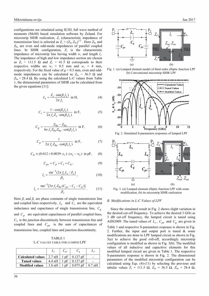
TABLE 1 L-C VALUES TABLE FOR LUMPED LPF
Ls Cps Cg La
Calculated values 2.7 nH 1 pF 0.127 pF - Tuned values 4.4 nH 1 pF 0.127 pF -
Modified values 3.8 nH 1 pF 0.075 pF 0.7 nH
(a) (b)
Fig. 1. (a) Lumped element model of third order elliptic function LPF (b) Conventional microstrip SIHR LPF
Fig. 2. Simulated S-parameters responses of lumped LPF
(a) (b)
Fig. 3. (a) Lumped element elliptic function LPF with some modification; (b) its microstrip SIHR realization
B. Modifications in L-C Values of LPF
Since the simulated result in Fig. 2 shows slight variation in the desired cut-off frequency. To achieve the desired 3 GHz as 3 dB cut-off frequency, the lumped circuit is tuned using ADS2009. The tuned values of sL , psC and gC are given in
Table 1 and respective S-parameters response is shown in Fig. 2. Further, the input and output port is tuned & some modifications are done to LPF lumped circuit as shown in Fig. 3(a) to achieve the good roll-off, accordingly microstrip configuration is modified as shown in Fig. 3(b). The modified values of all inductive and capacitive elements for this modified lumped circuit are given in Table 1. The respective S-parameters response is shown in Fig. 2. The dimensional parameters of the modified microstrip configuration can be calculated using Eqs. (4)-(11) by selecting the previous and tabular values Zs = 111.5 Ω, Z0e = 36.5 Ω, Z0o = 28.4 Ω,

June, 2017 Microwave Review
37
Zc = 41.5 Ω, ws = 0.5 mm, wc = 4 mm, g = 0.5 mm, Ls = 3.8 nH, Cps = 1 pF, Cg = 0.075 pF and La = 0.7 nH. The calculated dimensional parameters of this modified structure are given in Table 2 and respective S-parameter characteristic is shown in Fig. 4. Here, the 3 dB cut-off frequency is obtained as 3.7 GHz. So, further optimization is done using full wave electromagnetic simulator to get the 3 GHz cut-off frequency. The optimized dimensional parameters are also given in Table 2 and the respective S-parameter characteristic is shown in Fig. 4.
Fig. 4. Simulated S-parameter characteristics of microstrip LPF
(a) (b)
Fig. 5. (a) Microstrip SIHR loaded with radial stub, (b) its lumped equivalent model
TABLE 2 DIMENSIONAL PARAMETERS OF
MODIFIED MICROSTRIP CONFIGURATION
Parameters Calculated values Optimized values ws 0.5 mm 0.5 mm wc 4 mm 4 mm G 0.5 mm 0.5 mm ls 6.4 mm 11 mm la 1.1 mm 1.5 mm lc 4.15 mm 2.5 mm
C. Stop-Band Extension
The stop-band of optimized microstrip LPF is only up to 6.7 GHz. Further stop-band is extended by loading the SIHR with radial stub, such that overall size of microstrip configuration remains same, as shown in Fig. 5(a) by keeping all other parameters constant. Its lumped equivalent circuit is
shown in Fig. 5(b). The radial stub section is introduced to create the transmission zero at 7.5 GHz to extend the stop-band region as has property of intrinsic wide stop-band characteristic and accurate localization of a zero-point impedance [16]. The radial stub with dimensional parameters outer radii (ro), inner radii (ri) and spanning angle (θ) can be analyzed as a series combination of inductance (Lr) and capacitance (Cr) [19-20]. The dimensional parameters of radial stub are obtained as ro = 4.2 mm, ri = 0.53 mm and θ = 40 degree. The S-parameter characteristic of this microstrip configuration is shown in Fig. 4. Further extension of stop-band is achieved by inserting transmission line (quarter wavelength resonator) at 50 Ω line to generate transmission zero at 11 GHz with total length 5.1 mm and width 0.3 mm as shown in Fig. 6, by keeping other dimensions constant. This is the proposed microstrip LPF configuration. The dimensions shown in Fig. 6 are as a = 2.1 mm, b = 2.1 mm, c = 0.3 mm, s = 0.4 mm, wt = 0.3 mm, x = 10 mm, y = 7.5 mm. The simulated S-parameter characteristic of proposed LPF is depicted in Fig. 7. The simulation result shows the LPF with 3 dB cut-off frequency of 3 GHz having wide stop-band region with insertion loss (S21) below 10 dB up to 12 GHz.
Fig. 6. The proposed microstrip LPF
Fig. 7. The simulated S-parameter characteristic of proposed
microstrip LPF
III. EXPERIMENTAL RESULT
The proposed low cost, ultra-compact planar LPF with wide stop-band characteristic is designed by inserting radial stub and quarter wavelength resonator within the area of SIHR LPF structure. Further for validation, the proposed structure is fabricated using photolithographic method and tested using
Mikrotalasna revija Jun 2017
38
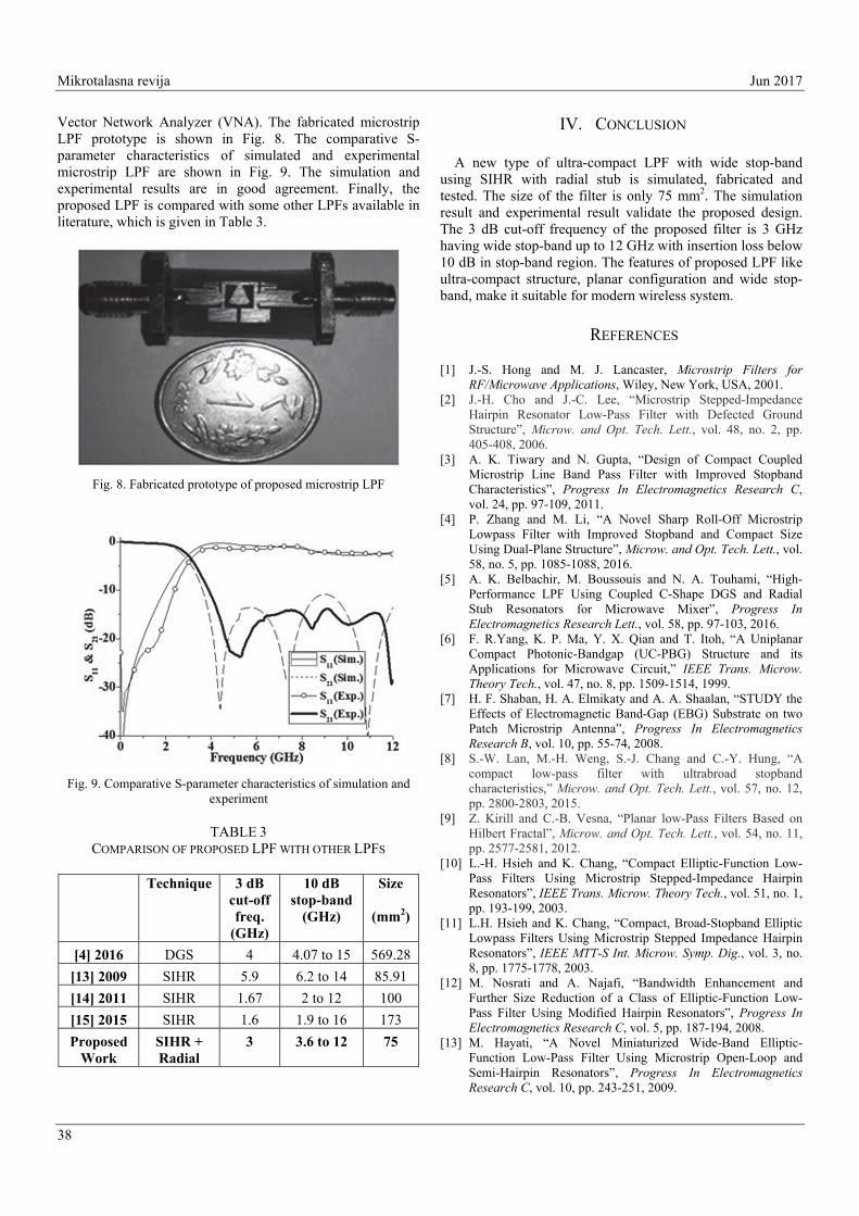
Vector Network Analyzer (VNA). The fabricated microstrip LPF prototype is shown in Fig. 8. The comparative S-parameter characteristics of simulated and experimental microstrip LPF are shown in Fig. 9. The simulation and experimental results are in good agreement. Finally, the proposed LPF is compared with some other LPFs available in literature, which is given in Table 3.
Fig. 8. Fabricated prototype of proposed microstrip LPF
Fig. 9. Comparative S-parameter characteristics of simulation and
experiment
TABLE 3 COMPARISON OF PROPOSED LPF WITH OTHER LPFS
Technique 3 dB cut-off freq.
(GHz)
10 dB stop-band
(GHz)
Size
(mm2)
[4] 2016 DGS 4 4.07 to 15 569.28
[13] 2009 SIHR 5.9 6.2 to 14 85.91
[14] 2011 SIHR 1.67 2 to 12 100
[15] 2015 SIHR 1.6 1.9 to 16 173
Proposed Work
SIHR + Radial
3 3.6 to 12 75
IV. CONCLUSION
A new type of ultra-compact LPF with wide stop-band using SIHR with radial stub is simulated, fabricated and tested. The size of the filter is only 75 mm2. The simulation result and experimental result validate the proposed design. The 3 dB cut-off frequency of the proposed filter is 3 GHz having wide stop-band up to 12 GHz with insertion loss below 10 dB in stop-band region. The features of proposed LPF like ultra-compact structure, planar configuration and wide stop-band, make it suitable for modern wireless system.
REFERENCES
[1] J.-S. Hong and M. J. Lancaster, Microstrip Filters for RF/Microwave Applications, Wiley, New York, USA, 2001.
[2] J.-H. Cho and J.-C. Lee, “Microstrip Stepped-Impedance Hairpin Resonator Low-Pass Filter with Defected Ground Structure”, Microw. and Opt. Tech. Lett., vol. 48, no. 2, pp. 405-408, 2006.
[3] A. K. Tiwary and N. Gupta, “Design of Compact Coupled Microstrip Line Band Pass Filter with Improved Stopband Characteristics”, Progress In Electromagnetics Research C, vol. 24, pp. 97-109, 2011.
[4] P. Zhang and M. Li, “A Novel Sharp Roll-Off Microstrip Lowpass Filter with Improved Stopband and Compact Size Using Dual-Plane Structure”, Microw. and Opt. Tech. Lett., vol. 58, no. 5, pp. 1085-1088, 2016.
[5] A. K. Belbachir, M. Boussouis and N. A. Touhami, “High-Performance LPF Using Coupled C-Shape DGS and Radial Stub Resonators for Microwave Mixer”, Progress In Electromagnetics Research Lett., vol. 58, pp. 97-103, 2016.
[6] F. R.Yang, K. P. Ma, Y. X. Qian and T. Itoh, “A Uniplanar Compact Photonic-Bandgap (UC-PBG) Structure and its Applications for Microwave Circuit,” IEEE Trans. Microw. Theory Tech., vol. 47, no. 8, pp. 1509-1514, 1999.
[7] H. F. Shaban, H. A. Elmikaty and A. A. Shaalan, “STUDY the Effects of Electromagnetic Band-Gap (EBG) Substrate on two Patch Microstrip Antenna”, Progress In Electromagnetics Research B, vol. 10, pp. 55-74, 2008.
[8] S.-W. Lan, M.-H. Weng, S.-J. Chang and C.-Y. Hung, “A compact low-pass filter with ultrabroad stopband characteristics,” Microw. and Opt. Tech. Lett., vol. 57, no. 12, pp. 2800-2803, 2015.
[9] Z. Kirill and C.-B. Vesna, “Planar low-Pass Filters Based on Hilbert Fractal”, Microw. and Opt. Tech. Lett., vol. 54, no. 11, pp. 2577-2581, 2012.
[10] L.-H. Hsieh and K. Chang, “Compact Elliptic-Function Low-Pass Filters Using Microstrip Stepped-Impedance Hairpin Resonators”, IEEE Trans. Microw. Theory Tech., vol. 51, no. 1, pp. 193-199, 2003.
[11] L.H. Hsieh and K. Chang, “Compact, Broad-Stopband Elliptic Lowpass Filters Using Microstrip Stepped Impedance Hairpin Resonators”, IEEE MTT-S Int. Microw. Symp. Dig., vol. 3, no. 8, pp. 1775-1778, 2003.
[12] M. Nosrati and A. Najafi, “Bandwidth Enhancement and Further Size Reduction of a Class of Elliptic-Function Low-Pass Filter Using Modified Hairpin Resonators”, Progress In Electromagnetics Research C, vol. 5, pp. 187-194, 2008.
[13] M. Hayati, “A Novel Miniaturized Wide-Band Elliptic-Function Low-Pass Filter Using Microstrip Open-Loop and Semi-Hairpin Resonators”, Progress In Electromagnetics Research C, vol. 10, pp. 243-251, 2009.

June, 2017 Microwave Review
39
[14] X. B. Wei, P. Wang, M.Q. Liu and Y. Shi, “Compact Wide-Stopband Lowpass Filter Using Stepped Impedance Hairpin Resonator With Radial Stubs”, Electronics Lett., vol. 47, no. 15, pp. 862-863, 2011.
[15] S. Liu, J. Xu and Z. Xu, “Compact lowpass Filter with Wide Stopband Using Stepped Impedance Hairpin Units”, Electronics Lett., vol. 51, no. 1, pp. 67-69, 2015.
[16] F. Giannini, R. Sorrentino and J. Vrba, “Planar Circuit Analysis of Microstrip Radial Stub”, IEEE Trans. Microw. Theory Tech., vol. 32, pp. 1652-1655, 1984.
[17] K. Ma and K. S. Yeo, “New Ultra-Wide Stopband Low-Pass Filter Using Transfromed Radial Stubs”, IEEE Trans. Microw. Theory Tech., vol. 59, no. 3, pp. 604-611, 2011.
[18] J. Xu, Y.-X. Ji, W. Wu and C. Miao, “Design of Miniaturized Microstrip LPF and Wideband BPF with Ultra-Wide Stopband”, IEEE Microw. And Wire. Comp. Lett., vol. 23, no. 8, pp. 397-399, 2013.
[19] P. K. Singh and A. K. Tiwary, “Novel Compact Dual Bandstop Filter Using Radial Stub”, Microw. Review, vol. 21, no. 1, pp. 17-22, 2015.
[20] P. K. Singh, A. K. Tiwary and N. Gupta, “Design of Radial Microstrip Band Pass Filter with Wide Stop-Band Characteristics for GPS Application”, Progress In Electromagnetics Research C, vol. 59, pp. 127–134, 2015.
Related Documents