Cable-Controlled Aeroshell Deceleration System Sashank Gummella, Sophomore, Aerospace Engineering Steven Kosvick, Sophomore, Aerospace Engineering Austin Scott, Sophomore, Aerospace Engineering Jose Tuason, Graduate Student, Aerospace Engineering Samuel Wywrot, Sophomore, Aerospace Engineering Faculty Advisor: Dr. Zachary Putnam, Aerospace Engineering 1

Welcome message from author
This document is posted to help you gain knowledge. Please leave a comment to let me know what you think about it! Share it to your friends and learn new things together.
Transcript

Cable-Controlled Aeroshell Deceleration System
Sashank Gummella, Sophomore, Aerospace EngineeringSteven Kosvick, Sophomore, Aerospace EngineeringAustin Scott, Sophomore, Aerospace EngineeringJose Tuason, Graduate Student, Aerospace EngineeringSamuel Wywrot, Sophomore, Aerospace Engineering
Faculty Advisor:Dr. Zachary Putnam, Aerospace Engineering
1
The Challenge• A vehicle capable of carrying 15-30 tonnes is necessary in
order to land on and return humans safely from Mars– Beyond the limits of 1960s-1970s technology
• Newly developed HIAD technology has great potential due to its efficient storage
• HIAD vehicles can mitigate deceleration forces on crew, loft and extend EDL events, and enable precision landing via generation of lift
2
Big Idea Challenge hosted by the NIA

CCADS - Design OverviewThe Cable Controlled Aerodynamic Decelerator System (CCADS) undergoes aeroshell shape morphing via tension applied through cables (fine control) and CG offsetting (coarse control) to control its lift vector.
• Key components:– HIAD aeroshell – Cables– Electric Motor
3

Design Specifications• Entry Vehicle
– Height: 7.9 m– Mass: 50 tonnes (estimated)
• Components– HIAD Aeroshell
• Diameter: 20 m at 70° half-cone angle
• Density (FTPS): 940 kg (estimation based on 3 kg/m2)
– Cables• Length: 25 m
4
*units in meters
Cables• Temperature range 350°C-450°C• Material
– Carbon-based composite (CFCC, C-C) – Graphite fiber-phthalonitrile– Thermal resistant
• Gutters/Sleeves– Protect and guide cables during morphing– Made of heat resistant and low-friction material
• Three Torus Interface Configurations
5
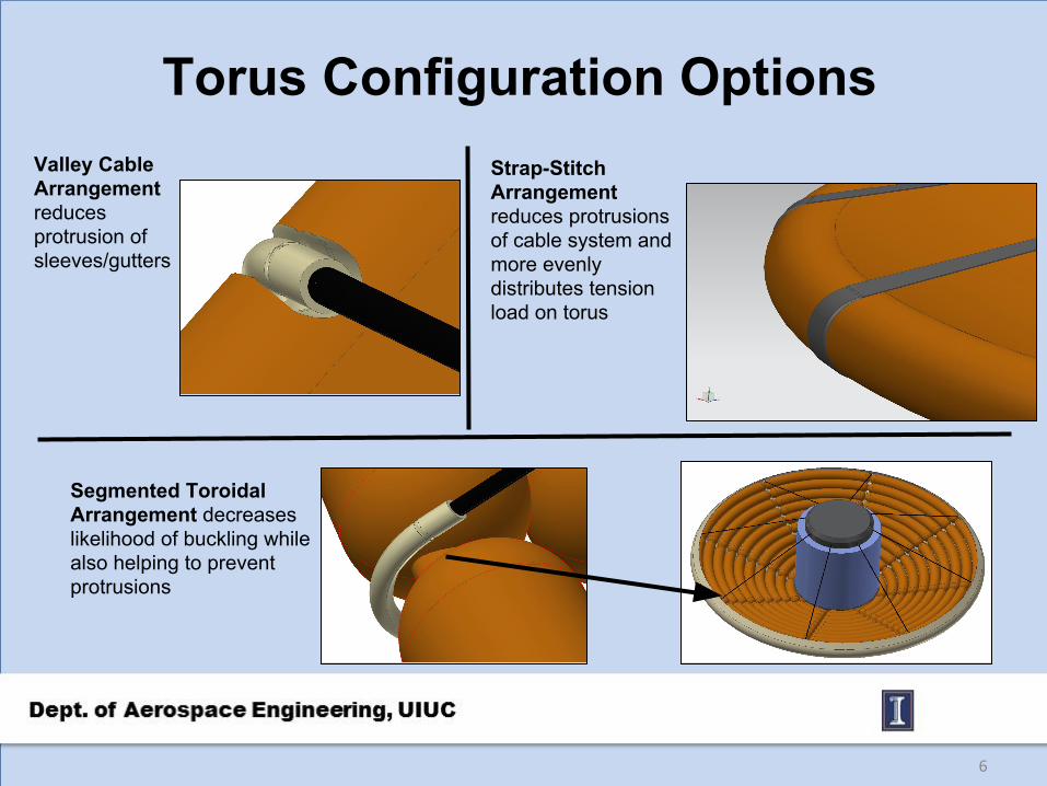
Torus Configuration Options
6
Valley Cable Arrangement reduces protrusion of sleeves/gutters
Segmented Toroidal Arrangement decreases likelihood of buckling while also helping to prevent protrusions
Strap-Stitch Arrangement reduces protrusions of cable system and more evenly distributes tension load on torus
Electric Motor • One electric motor housing on top of upper section of
payload compartment– Applies tension to cables to morph the aeroshell– Increases maneuverability
• BLDC motors must be tailored to mission concept• Structural analysis and testing of aeroshell loads
– Effect of tensile forces on shape-morphing – Power and mass of BLDC motor per cable
7

Mission Profile• Deployment and configuration
– Aeroshell inflation occurs prior to atmospheric entry
– Nominal aeroshell configuration is defined by a 70° half-cone angle
• Point 1: 70 km, initialize control• Point 2: 50 km, start of vehicle loft• Point 3: 70 km, suspension of
control to conserve energy • Point 4: 70 km, re-initialize control• Point 5: 11 km, terminal descent
phase
8
1
2
34
5

Control• Coarse control → CG shifting
– Large adjustments to L/D• Fine control → cable-controlled
aeroshell morphing– Small adjustments to L/D
• Even small changes in L/D yield noticeable changes in range
9
Above Images credited to Justin Green

Downrange and Crossrange Control• Test conditions
– Velocity: 5800 m/s– Flight Path Angle: -10°– Ballistic Coefficient: 99 kg/m2
– Bank angle:• 0° for downrange simulation• 45° bank angle for crossrange simulation
• Downrange Δkm of 800 km between 0.05 to 0.25 L/D at 0° bank angle
– Δkm of 590 km between 0.25 to 0.30 L/D• Crossrange Δkm of 35 km over same L/D at 45° bank
angle– Δkm 33 km between 0.25 to 0.30 L/D– Substantial reduction in downrange capability with
banks greater than 25°• Fine tuning via Shape Morphing allows for increased
landing accuracy
10
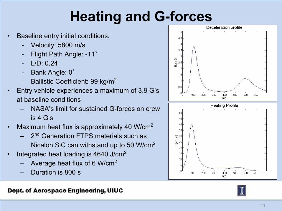
Heating and G-forces• Baseline entry initial conditions:
- Velocity: 5800 m/s- Flight Path Angle: -11゜- L/D: 0.24- Bank Angle: 0゜- Ballistic Coefficient: 99 kg/m2
• Entry vehicle experiences a maximum of 3.9 G’s at baseline conditions– NASA’s limit for sustained G-forces on crew
is 4 G’s• Maximum heat flux is approximately 40 W/cm2
– 2nd Generation FTPS materials such as Nicalon SiC can withstand up to 50 W/cm2
• Integrated heat loading is 4640 J/cm2
– Average heat flux of 6 W/cm2
– Duration is 800 s
11
Testing and Future Development • Test alternative cable types, materials, configurations• Limitations of shape morphing
– Buckling and creasing detection– FTPS wrinkling– Aeroshell inflation pressure
• Mission Concepts– Crewed and uncrewed mission potential– Low-altitude geographic surveyance – Ionospheric and weather pattern observation– Recyclable parts (explorers could reuse motors/cables)
12

Summary
• CCADS is able to deliver 25 or higher tonne payloads to Mars using HIAD technology
• Scalable and relatively lightweight system• Provides coarse and fine L/D shifting in order to accurately
change and refine course• Is able to loft and extend EDL time frame to reduce
deceleration forces and heat flux • Potential to be cheaper than pre-existing technology and
alternatives
13

Acknowledgements• Judges
– Neil Cheatwood– Anthony Calomino– Michelle Munk– Dick Powell– Steve Sandford– Mary Beth Wusk
• NIA – Stacy Dees– Carolyn Sager
• NASA Langley Research Center
14
Related Documents