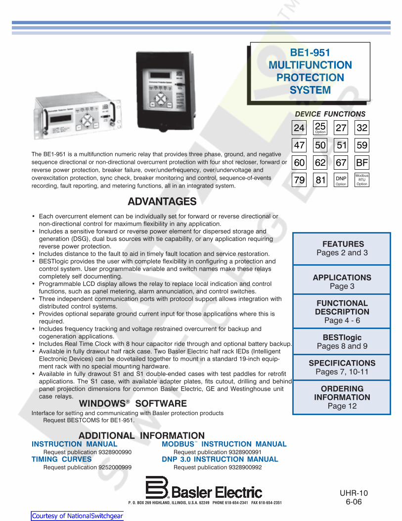
UHR-10 6-06 P. O. BOX 269 HIGHLAND, ILLINOIS, U.S.A. 62249 PHONE 618-654-2341 FAX 618-654-2351 BE1-951 MULTIFUNCTION PROTECTION SYSTEM The BE1-951 is a multifunction numeric relay that provides three phase, ground, and negative sequence directional or non-directional overcurrent protection with four shot recloser, forward or reverse power protection, breaker failure, over/underfrequency, over/undervoltage and overexcitation protection, sync check, breaker monitoring and control, sequence-of-events recording, fault reporting, and metering functions, all in an integrated system. ADVANTAGES • Each overcurrent element can be individually set for forward or reverse directional or non-directional control for maximum flexibility in any application. • Includes a sensitive forward or reverse power element for dispersed storage and generation (DSG), dual bus sources with tie capability, or any application requiring reverse power protection. • Includes distance to the fault to aid in timely fault location and service restoration. • BESTlogic provides the user with complete flexibility in configuring a protection and control system. User programmable variable and switch names make these relays completely self documenting. • Programmable LCD display allows the relay to replace local indication and control functions, such as panel metering, alarm annunciation, and control switches. • Three independent communication ports with protocol support allows integration with distributed control systems. • Provides optional separate ground current input for those applications where this is required. • Includes frequency tracking and voltage restrained overcurrent for backup and cogeneration applications. • Includes Real Time Clock with 8 hour capacitor ride through and optional battery backup. • Available in fully drawout half rack case. Two Basler Electric half rack IEDs (Intelligent Electronic Devices) can be dovetailed together to mount in a standard 19-inch equip- ment rack with no special mounting hardware. • Available in fully drawout S1 and S1 double-ended cases with test paddles for retrofit applications. The S1 case, with available adapter plates, fits cutout, drilling and behind panel projection dimensions for common Basler Electric, GE and Westinghouse unit case relays. FEATURES Pages 2 and 3 APPLICATIONS Page 3 FUNCTIONAL DESCRIPTION Page 4 - 6 BESTlogic Pages 8 and 9 SPECIFICATIONS Pages 7, 10-11 ORDERING INFORMATION Page 12 INSTRUCTION MANUAL MODBUS INSTRUCTION MANUAL Request publication 9328900990 Request publication 9328900991 TIMING CURVES DNP 3.0 INSTRUCTION MANUAL Request publication 9252000999 Request publication 9328900992 ADDITIONAL INFORMATION WINDOWS ® SOFTWARE Interface for setting and communicating with Basler protection products Request BESTCOMS for BE1-951. DEVICE FUNCTIONS

Welcome message from author
This document is posted to help you gain knowledge. Please leave a comment to let me know what you think about it! Share it to your friends and learn new things together.
Transcript
BE1-951
UHR-106-06P O BOX 269 HIGHLAND ILLINOIS USA 62249 PHONE 618-654-2341 FAX 618-654-2351
BE1-951MULTIFUNCTION
PROTECTIONSYSTEM
The BE1-951 is a multifunction numeric relay that provides three phase ground and negativesequence directional or non-directional overcurrent protection with four shot recloser forward orreverse power protection breaker failure overunderfrequency overundervoltage andoverexcitation protection sync check breaker monitoring and control sequence-of-eventsrecording fault reporting and metering functions all in an integrated system
ADVANTAGESbull Each overcurrent element can be individually set for forward or reverse directional or
non-directional control for maximum flexibility in any applicationbull Includes a sensitive forward or reverse power element for dispersed storage and
generation (DSG) dual bus sources with tie capability or any application requiringreverse power protection
bull Includes distance to the fault to aid in timely fault location and service restorationbull BESTlogic provides the user with complete flexibility in configuring a protection and
control system User programmable variable and switch names make these relayscompletely self documenting
bull Programmable LCD display allows the relay to replace local indication and controlfunctions such as panel metering alarm annunciation and control switches
bull Three independent communication ports with protocol support allows integration withdistributed control systems
bull Provides optional separate ground current input for those applications where this isrequired
bull Includes frequency tracking and voltage restrained overcurrent for backup andcogeneration applications
bull Includes Real Time Clock with 8 hour capacitor ride through and optional battery backupbull Available in fully drawout half rack case Two Basler Electric half rack IEDs (Intelligent
Electronic Devices) can be dovetailed together to mount in a standard 19-inch equip-ment rack with no special mounting hardware
bull Available in fully drawout S1 and S1 double-ended cases with test paddles for retrofitapplications The S1 case with available adapter plates fits cutout drilling and behindpanel projection dimensions for common Basler Electric GE and Westinghouse unitcase relays
FEATURESPages 2 and 3
APPLICATIONSPage 3
FUNCTIONALDESCRIPTION
Page 4 - 6
BESTlogicPages 8 and 9
SPECIFICATIONSPages 7 10-11
ORDERINGINFORMATION
Page 12
INSTRUCTION MANUAL MODBUS INSTRUCTION MANUALRequest publication 9328900990 Request publication 9328900991
TIMING CURVES DNP 30 INSTRUCTION MANUALRequest publication 9252000999 Request publication 9328900992
ADDITIONAL INFORMATION
WINDOWSreg SOFTWAREInterface for setting and communicating with Basler protection products Request BESTCOMS for BE1-951
DEVICE FUNCTIONS
Courtesy of NationalSwitchgearcom
BE1-951
2
FEATURESPROTECTIONbull Phase Neutral and Negative Sequence Instantaneous
Overcurrent elements with settable time delay 50TP150TP 50TN 150TN 50TQ 150TQ
bull Phase Neutral and Negative Sequence TimeOvercurrent elements 51P 51N 151N 51Q(51P elements can have voltage restraint)
bull Each overcurrent element can be set for forwardreverse or nondirectional control (67P 67N 67Q)Directional control is by Positive (671) Negative (672)Zero Sequence Voltage (670V) and Zero SequenceCurrent (670I) polarized directional units
bull All US and IEC timing curves plus user program-mable curve
bull Minimizes transient overreach and overtravel onovercurrent elements
bull Optional separate ground current input provides zerosequence current polarization andor groundovercurrent protection for a separate ground CT
bull Phase Undervoltage and Overvoltage elements27P 59P Elements use a 1 of 3 2 of 3 or 3 of 3 logicand monitor either line-line or line-ground voltages
bull Auxiliary Undervoltage and Overvoltage elements27X 59X 159X Elements monitor either fundamental orthird harmonic on the optional auxiliary 4th VT input orfundamental phase residual 3V0 of the phase inputs
bull Overexcitation volts per Hertz element 24bull Forward or Reverse Power 32bull Negative Sequence Overvoltage element 47bull OverUnder Frequency elements 81 181 281 381
481 581bull Each 81 element can be assigned to monitor 3 phase VT
input (VP) or Auxiliary voltage input (Vx)bull Breaker Failure protection function BFbull Two general purpose logic timers 62 162bull Programmable Logic using BESTlogicbull Four protection setting groups with external or automatic
(cold load pickup load unbalance recloser shot)selection modes
bull Sync check with dead linedead bus voltage monitorlogic 25 25VM (Requires optional 4th VT sensingcircuit)
bull Fuse loss detection protects against false trip due to lossof voltage sensing 60FL
CONTROLbull Four shot recloser with zone sequence coordination and
sequence controlled protective element blockingfunctions
bull Virtual breaker control switchmdashcontrollable from bothHMI and com ports 101
bull Four virtual selector switchesmdashcontrollable from bothHMI and com ports 43 143 243 343
bull Virtual lockout latches 86 186 Status is stored inEEPROM
bull Communication port control of 101 and 43 switchesallows for SCADA control of relay and breaker
INSTRUMENTATIONbull Real time A B C phase current voltage and frequency
and derived neutral and negative sequence current andvoltage
bull Real Time per phase and 3 phase Watts Vars and3 phase Power Factor
REPORTSbull Current demands for phase neutral and negative
sequence currents and forward and reverse watts andvarsmdashmagnitudes and time stamps are recorded fortodays peak yesterdays peak and peak since reset
bull Optional 4000 point log of demand readingsbull kWh and kvarh forward and reversebull Breaker operations counter and contact interruption duty
FAULT RECORDINGbull 255 event sequence of events report with IO and alarm
sub-reportsbull Fault Reporting 1 or 2 oscillography records per fault
reportbull 16 fault summary reports two most recent Fault
Summary Records saved to non-volatile memorybull Total number of oscillography records settable from 6 to
16bull Total of 240 cycles oscillography memory 12
samplescyclebull COMTRADE formatbull Load compensated distance to fault
COMMUNICATION PORTSbull Three independent general purpose communication
ports- Front RS-232 ASCII communications- Rear RS-232 ASCII communications- Rear RS-485 ASCII Modbus DNP 30 and TNP protocols
bull IRIG time sync (unmodulated)
SELF TEST AND ALARM FUNCTIONSbull Relay fail major alarm and minor alarm LEDs and
fail-safe alarm output contact (closed or open)See style chart page 12 for ordering information
bull Extensive internal diagnostics monitor all internalfunctions of the relay
bull More than 20 additional alarm pointsmdashprogrammablefor major or minor priorityIncluding- Phase current and forward and reverse watt and
var demand alarm- Neutral and negative sequence unbalance demand
alarms- Three breaker alarm points programmable for slow trip
interruption duty threshold or operations counter- Trip circuit voltage and continuity monitor- Close circuit monitor via BESTlogic
PROGRAMMABLE IObull Four programmable inputsbull Five programmable outputs and one dedicated
programmable alarm output
Courtesy of NationalSwitchgearcom
BE1-951
3
APPLICATIONS
The BE1-951 Multifunction Protection System provides three phase ground and negative sequence overcurrentvoltage and frequency protection and is intended for use in any directional or non-directional overcurrent protectionapplication Its unique capabilities make it ideally suited for applications with the following requirements
bull Applications that require low burden to extend the linear range of CTsbull Applications that require high accuracy across a wide frequency range such as for motor generator and
generator step-up transformer protection or in cogeneration facilitiesbull Applications that require the flexibility provided by wide setting ranges multiple setting groups and multiple
coordination curves in one unitbull Applications that require the economy and space savings provided by a multifunction multiphase unit This one
unit can provide all of the protection control metering and local and remote indication functions required on atypical circuit
bull Applications that require directional control and fault locatingbull Applications requiring protection of an intertie between dispersed storage and generation facilities (DSG) and a
utilitybull Transformer backup applications where overexcitation protection is requiredbull Applications that require communications and protocol supportbull Applications where the capabilities of a digital multifunction relay are required yet drawout construction is also
desirablebull Applications where bus protection is provided by a high speed overcurrent blocking scheme on the transformer
bus mains instead of a dedicated bus differential circuitbull Applications where the small size and limited behind-panel projection facilitates modernizing protection and
control systems in existing substations
FEATURES continued
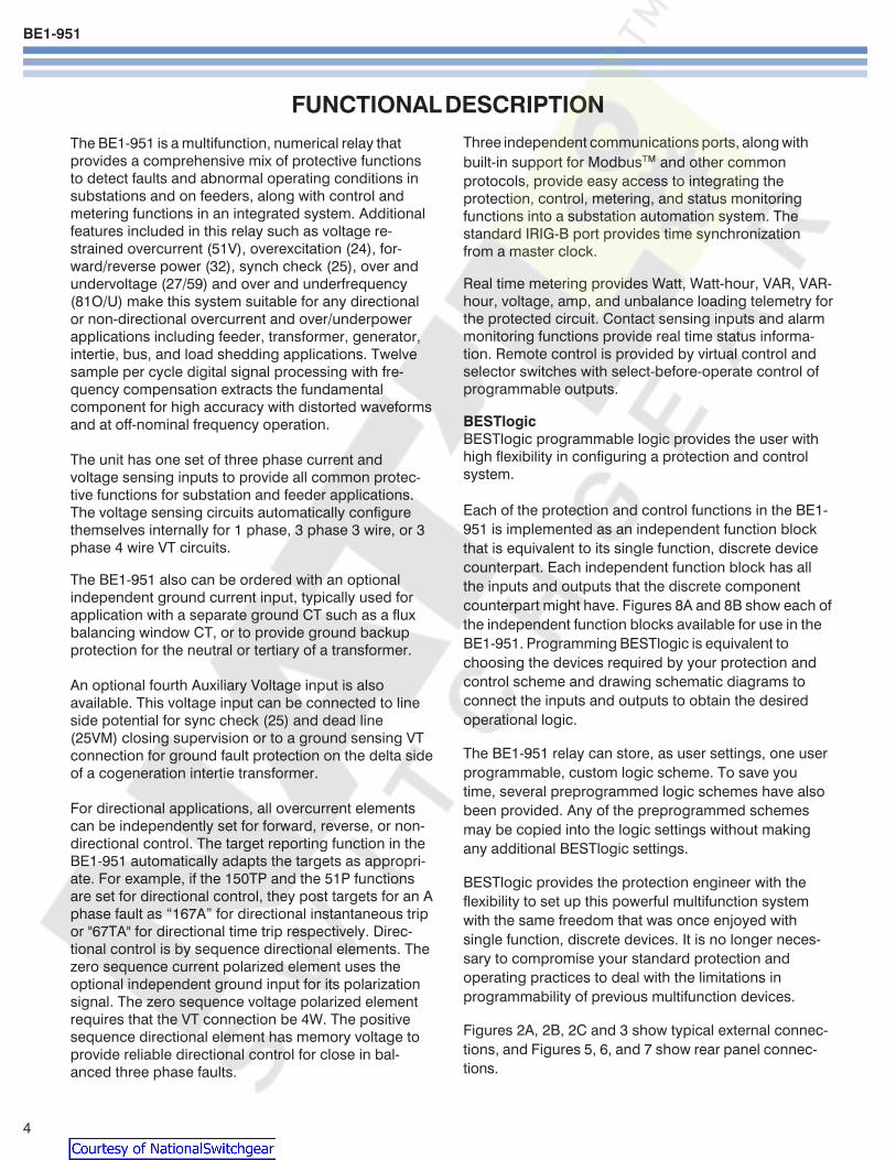
Figure 1 - Advanced HMI (Human Machine Interface) shown withoptional Direct Access Virtual Control Panel
HARDWARE FEATURESbull Three case configurations
- S1 BaslerGE style (with test plug)- S1 Double ended BaslerGE style (with test plugs)- H1 Half Rack
bull Active CT technology for low burden and increaseddynamic range
bull Flash Memory for upgrading embedded programmingwithout changing chips
bull Real Time Clock with 8 hour capacitor ride through andoptional battery backup
bull Integral HMI with 2x16 character displaybull Wide range acdc power supply options provide long
holdup time to ride through dips on ac power source(100 ms with 4 output relays energized upon completeloss of source Starting voltage 125Vac for Option 1(48125Vacdc) and 250Vac for Option 2 (125250Vacdc))
Courtesy of NationalSwitchgearcom
BE1-951
4
FUNCTIONAL DESCRIPTION
The BE1-951 is a multifunction numerical relay thatprovides a comprehensive mix of protective functionsto detect faults and abnormal operating conditions insubstations and on feeders along with control andmetering functions in an integrated system Additionalfeatures included in this relay such as voltage re-strained overcurrent (51V) overexcitation (24) for-wardreverse power (32) synch check (25) over andundervoltage (2759) and over and underfrequency(81OU) make this system suitable for any directionalor non-directional overcurrent and overunderpowerapplications including feeder transformer generatorintertie bus and load shedding applications Twelvesample per cycle digital signal processing with fre-quency compensation extracts the fundamentalcomponent for high accuracy with distorted waveformsand at off-nominal frequency operation
The unit has one set of three phase current andvoltage sensing inputs to provide all common protec-tive functions for substation and feeder applicationsThe voltage sensing circuits automatically configurethemselves internally for 1 phase 3 phase 3 wire or 3phase 4 wire VT circuits
The BE1-951 also can be ordered with an optionalindependent ground current input typically used forapplication with a separate ground CT such as a fluxbalancing window CT or to provide ground backupprotection for the neutral or tertiary of a transformer
An optional fourth Auxiliary Voltage input is alsoavailable This voltage input can be connected to lineside potential for sync check (25) and dead line(25VM) closing supervision or to a ground sensing VTconnection for ground fault protection on the delta sideof a cogeneration intertie transformer
For directional applications all overcurrent elementscan be independently set for forward reverse or non-directional control The target reporting function in theBE1-951 automatically adapts the targets as appropri-ate For example if the 150TP and the 51P functionsare set for directional control they post targets for an Aphase fault as ldquo167Ardquo for directional instantaneous tripor 67TA for directional time trip respectively Direc-tional control is by sequence directional elements Thezero sequence current polarized element uses theoptional independent ground input for its polarizationsignal The zero sequence voltage polarized elementrequires that the VT connection be 4W The positivesequence directional element has memory voltage toprovide reliable directional control for close in bal-anced three phase faults
Three independent communications ports along withbuilt-in support for Modbus and other commonprotocols provide easy access to integrating theprotection control metering and status monitoringfunctions into a substation automation system Thestandard IRIG-B port provides time synchronizationfrom a master clock
Real time metering provides Watt Watt-hour VAR VAR-hour voltage amp and unbalance loading telemetry forthe protected circuit Contact sensing inputs and alarmmonitoring functions provide real time status informa-tion Remote control is provided by virtual control andselector switches with select-before-operate control ofprogrammable outputs
BESTlogicBESTlogic programmable logic provides the user withhigh flexibility in configuring a protection and controlsystem
Each of the protection and control functions in the BE1-951 is implemented as an independent function blockthat is equivalent to its single function discrete devicecounterpart Each independent function block has allthe inputs and outputs that the discrete componentcounterpart might have Figures 8A and 8B show each ofthe independent function blocks available for use in theBE1-951 Programming BESTlogic is equivalent tochoosing the devices required by your protection andcontrol scheme and drawing schematic diagrams toconnect the inputs and outputs to obtain the desiredoperational logic
The BE1-951 relay can store as user settings one userprogrammable custom logic scheme To save youtime several preprogrammed logic schemes have alsobeen provided Any of the preprogrammed schemesmay be copied into the logic settings without makingany additional BESTlogic settings
BESTlogic provides the protection engineer with theflexibility to set up this powerful multifunction systemwith the same freedom that was once enjoyed withsingle function discrete devices It is no longer neces-sary to compromise your standard protection andoperating practices to deal with the limitations inprogrammability of previous multifunction devices
Figures 2A 2B 2C and 3 show typical external connec-tions and Figures 5 6 and 7 show rear panel connec-tions
Courtesy of NationalSwitchgearcom
BE1-951
5
Figure 2A - Typical External Sensing Connections -Feeder Breaker Application
FUNCTIONAL DESCRIPTION continued
Figure 2B - Typical External Sensing Connections -Transformer Backup Application
Figure 2C - Typical Alternate Connections for Vx and IG
Figure 3 - Typical External Connections
Courtesy of NationalSwitchgearcom
BE1-951
6
FUNCTIONAL DESCRIPTION continued
Fig
ure
6 -
BE
1-95
1 H
1 R
ear P
anel
Co
nn
ectio
ns
Figure 5 - BE1-951 S1 Rear Panel Connections
Figure 4 - Typical Application Single Line
Based upon pre-programmed logic OC-W-79Not all available protection and control functions are shown
Figure 7 - BE1-951 S1 Double-EndedRear Panel Connections
Courtesy of NationalSwitchgearcom
BE1-951
7
GENERAL SPECIFICATIONS5 Amp CURRENT INPUTS
Continuous rating 20AOne Sec Rating 400ASaturation limit 150ABurden lt10milliohms
1 Amp CURRENT INPUTSContinuous rating 4AOne Sec rating 250ASaturation limit 30ABurden lt22milliohms
PHASE AC VOLTAGE INPUTSContinuous 300V Line to LineOne Sec rating 600V Line to NeutralBurden Less than 1VA 300Vac
AUXILIARY AC VOLTAGE INPUTContinuous 150VOne Sec rating 600VBurden Less than 1VA 150Vac
AD CONVERTERSampling Rate 12cycle adjusted to
input frequency 10-75Hz
POWER SUPPLYOption 1 DC range 35 - 150V
AC range 55 - 135VOption 2 DC range 90 - 300V
AC range 90 - 270VOption 3 DC range 17 - 32V (down
to 8V for momentary dips)Burden 6 watts continuous
8 watts maximum withall outputs energized
TRIP CONTACTSMake and carry 30A (02sec)Continuous 7ABreak 03A DC (LR=004)
CONTROL INPUTSWetting voltage range Same as control power
supply option Low Range High Range
Power Turn-on Turn-on Supply Voltage Voltage
Option Range Burden Range Burden
1) 48125VacVdc 26-38V 13k ohms 69-100V 24k ohms
2) 125250VacVdc 69-100V 25k ohms 138-200V 54k ohms
3) 24Vdc 5-8Vdc 7k ohms NA NA
Control inputs recognize both DC and AC voltages
COMMUNICATION PORTSResponse time lt100mSec for metering
and control functionsBaud rate 300 - 19200
ELECTRICAL ENVIRONMENTbull IEEE C3790-1989 Standard for Relays and Relay
Systems Associated with Electric Power Apparatusbull IEC 255-5 Insulation Test for Electrical Relays
Impulse and Dielectric Strength (2000Vac at 5060Hz)bull IEEE C37901-1989 Standard Surge Withstand Cap-
ability Tests for Relays and Relay Systems Associatedwith Electric Power Apparatus
bull IEC 255-22-1 1MHz Burst Disturbance Tests for Elec-trical Disturbance Tests for Measuring Relays andProtection Equipment
bull EN 61000-4-4 Electrical Fast TransientBurst ImmunityTest
bull EN 61000-4-3 Radiated Radio-frequency Electro-magnetic Field Immunity Test
bull Type tested using a 5-watt hand-held transceiver inthe ranges of 144 and 440MHz with the antennaplaced within 6 inches of the relay
bull IEEE C37903 (Jan 01) Draft Standard ElectrostaticDischarge Tests for Protective Relays
bull EN 61000-4-2 Electrostatic Discharge Immunity Test
MECHANICAL ENVIRONMENTbull Operating temperature range -40degC to 70degC
(-40degF to 158degF)LCD Display is inoperative below -20degC
bull Storage temperature range -40degC to 70degC(-40degF to 158degF)
bull Humidity Qualified to IEC 68-2-38 1st Edition1974 Basic Environmental Test ProceduresPart 2 Test ZAD Composite TemperatureHumidity Cyclic Test
bull Qualified to IEC 255-21-1 (Class 1) Vibration Testsfor Electrical Relays
bull Qualified to IEC 255-21-2 (Class 1) Shock andBump Tests for Electrical Relays
CERTIFICATIONSUL Recognized File E97033CSA Certified File LR23131Gost R Certified POCC USME05B03391DNP 30 IED Certified Subset Level 2 62000 by SUBNET Solutions Inc
CASE SIZEH1 1050W x 347H x 910D with mounting
flanges (85W without mounting flanges)S1 665W x 932H x 951D (includes relay cover)S1 double-ended 665W x 932H x 951D
(includes relay cover)
SHIPPING WEIGHTH1 Approx 10 poundsS1 Approx 112 poundsS1 double-ended 128 pounds
WARRANTY7 years
Courtesy of NationalSwitchgearcom
BE1-951
8
Figure 8A - BESTlogic Function Blocks
Courtesy of NationalSwitchgearcom
BE1-951
9
Figure 8B - BESTlogic Function Blocks
Courtesy of NationalSwitchgearcom
BE1-951
10
PERFORMANCE SPECIFICATIONS
INSTANTANEOUS OVERCURRENT WITHSETTABLE DELAY (50TP 150TP 50TN 150TN50TQ 150TQ)
Pickup 5A CT 05 - 1500A1A CT 01 - 300A
PU time with TD=0000 Sec2 cyc for P N ampG 5 x PU3 cyc for Q 5 x PU
Delay time 0000 - 60 secTime Accuracy plusmn05 or plusmnfrac12 cyc for P and N
plusmn05 or plusmn1 cyc for Q
TIME OVERCURRENT (51P 51N 151N 51Q)Pickup 5A CT 05 - 160A
1A CT 01 - 320ATime dial TD=K=0 - 99 for 46 curve
TD=00 - 99 for all other curvesTime-Current Characteristics
The following expression describes the inversetime current characteristic for each curve
TT = AD + BD + K = Time to trip
MN-C
TR = RD = Time for decaying reset
M2-1
where D = Time dial M = Multiple of PU and A BC N K and R are constants that govern the shapeof each curve The protection engineer can set theconstants for the P (programmable) curve toachieve virtually any characteristic
51P VOLTAGE CONTROL (27R)Control Modes Uncontrolled voltage
controlled voltage restrainedControlRestraint Range 30 - 250VRestrained Mode Characteristic (see below)
ConstantsCurveType
S1
S2
L1
L2
D
M
I1
I2
V1
V2
E1
E2
A
B
C
G
F
46
P
S1 S2 = CO Short Inv IAC Short Inv A = IEC Standard InverseL1 L2 = CO Long Inv IAC Long Inv B = IEC Very InverseD = CO Definite Time C = IEC Extremely InverseM = CO Moderately Inverse G = IEC Long Time InverseI1 I2 = CO Inverse IAC Inverse F = Fixed TimeV1 V2 = CO Very Inv IAC Very Inv 46 = Negative Sequence OvercurrentE1 E2 = CO Ext Inverse IAC Ext Inverse P = Programmable
Constant A is variable for the 46 curve and is determined as necessary based on system full load current setting minimum pickup and K factor settings
DIRECTIONAL CONTROL (ALL OVERCURRENT)Mode Forward Reverse
Nondirectional67P Polarization Positive Sequence wMemory
Negative Sequence67Q Polarization Negative Sequence67N Polarization Selectable any combination
Zero Sequence Voltage(Requires 4W VT)Zero Sequence Current(Requires IG)Negative Sequence
BREAKER FAILURE (BF)Time 50 - 999mSecDropout 5A CT 05A
1A CT 01ATime Accuracy plusmn05 or +1frac14 cyc - frac12 cyc
VOLTSHZ (24)Pickup 05 - 6VHzDelay Time Inverse Squared Curve
DT ETTT = (M-1)2 TR = DR x FST x 100TT = Time to Trip TR = Time to ResetDT = Time Dial Trip DR = Time Dial Reset
Actual VHzM = Pickup VHz ET = Elapsed TimeFST = Full Scale Trip Time (TT)
A B C N K R
02663 003393 1000 12969 0028 05000
00286 002080 1000 09844 0028 00940
56143 218592 1000 1000 0028 15750
23955 000000 1000 03125 0028 78001
04797 021359 1000 15625 0028 08750
03022 012840 1000 05000 0028 17500
89341 017966 1000 20938 0028 90000
02747 01042 1000 04375 0028 08868
54678 010814 1000 20469 0028 55000
44309 00991 1000 19531 0028 58231
77624 002758 1000 20938 0028 77500
49883 00129 1000 20469 0028 47742
001414 000000 1000 00200 0028 20000
14636 000000 1000 10469 0028 32500
82506 000000 1000 20469 0028 80000
121212 000000 1000 1000 0028 29000
00000 100000 0000 00000 0028 10000
0 0 2 0028 100
0 to 600 0 to 25 0 to 1 5 to 25 0028 0 to 30
Courtesy of NationalSwitchgearcom
BE1-951
11
PERFORMANCE SPECIFICATIONS continued
PHASE OVERUNDERVOLTAGE (27P 59P)Mode 1 of 3 2 of 3 3 of 3Pickup 100-300VL-L or 100-300VL-NDelay Time 0050 - 600sec
NEGATIVE SEQUENCE OVERVOLTAGE (47)Pickup 10 - 300VL-NDelay Time 0050 - 600sec
AUXILIARY 3V0 OVERUNDERVOLTAGE(27X 59X 159X)
Mode Fundamental VX 3 phase Residual (3V0)3rd Harmonic VX
Pickup 10 - 150VDelay Time 0050 - 600 Sec
POWER (32)Mode Forward ReversePickup 5A 10 - 6000 Watts 3 ph
1A 10 - 1200 Watts 3 phPickup Accuracy plusmn3Delay Time 0050 - 600 Sec
FREQUENCY (81 181 281 381 481 581)Mode Over UnderPickup 4000 - 7000 HzDelay Time 0000 - 600 SecTime Accuracy plusmn05 or +1 cyc -0 cyc(Min trip time affected by min 3 cyc securitycount)
GENERAL PURPOSE LOGIC TIMERS (62 162)Mode PUDO
1 Shot Non-Retrig1 Shot RetrigIntegratingLatch
T1 and T2 Delay Time 0000 - 9999 SecTime Accuracy plusmn05 or plusmnfrac34 cyc
RECLOSER (79)Mode Power up to close
Power up to lockoutReclose Shots 0 - 4Reclose Reset FailMax Cycle Timers 0100 - 600 SecTime Accuracy plusmn05 or
+1frac34 cyc-0 cyc
CURRENT PICKUP ACCURACY (All 50 and 51)Phase and Ground 5A 2 or 50mA
1A 2 or 10mANeutral and Negative 5A 3 or 75mASequence 1A 3 or 75mA
VOLTAGE PICKUP ACCURACY (All 27 47 and 59)Phase (VL-L or VL-N) plusmn2 or plusmn05VPhase 3V0 and V2 plusmn2 or plusmn05V
DEFINITE TIME ACCURACY UNLESS OTHERWISESTATED (All 27 47 and 59)
Definite Time Accuracy plusmn05 or plusmn1 cyc
SETTING GROUPSSetting Groups 4Control Modes AutomaticCLP
Recloser shotDynamic load or unbalanceExternal Discrete input logicBinary Input Logic
METERINGCurrent Range 5A 05 to 150
1A 01 to 30Current Accuracy plusmn1Phase Voltage Range 3W 0 - 300 VL-L
4W 0 - 300 VL-L
Phase Voltage Accuracy plusmn05 for50VltVL-Llt300V
WattVAR 5A 0 to plusmn75001A 0 to plusmn1500
Watt Accuracy 1 Unity PFVAR Accuracy 1 Zero PFEnergy 0 to plusmn10E12
(FR registers)Frequency 10 - 75HzFrequency Accuracy 001Hz
DEMANDS (IA IB IC IN IQ Fwd Watts Rvs WattsFwd VARs Rvs VARs)
Demand Interval 1 - 60 minDemand Mode Thermal
BREAKER MONITORINGDuty Mode I or I2
Duty Alarm Range 0 - to 100Op Counter Alarm Range 0 - 99999Trip Time Alarm Range 20 - 1000mSec
SYNC CHECK (25)Delta Phase Angle 1 - 45 degreesDelta Voltage Magnitude 1 - 20VDelta Frequency 001 - 050Hz
SYNC CHECK VOLTAGE MONITOR (25VM)Dead Threshold 10 - 150VLive Threshold 10 - 150VDropout Time Delay 0050 - 600secLogic Dead PhaseDead Aux
Dead PhaseLive AuxLive PhaseDead Aux
Two Independent outputs 25VM1 and 25VM2
Courtesy of NationalSwitchgearcom
BE1-951
ORDERINGSAMPLE STYLE NUMBERThe style number identification chart defines the electrical characteristics and operation features included inBE1-951 relays For example if the style number were BE1-951 E3N1H0Y the device would have the following
BE1-951(E) - 5 Amp nominal system with 5 Amp Independent Ground Input(3) - Three phase voltage sensing(N) - Not applicable(1) - 48125VacVdc power supply(H) - Half Rack Case Normally Closed Alarm(0) - ASCII Communications(Y) - 4000 point Load Profile Demand Log
Printed in USAPrinted in USAPrinted in USAPrinted in USAPrinted in USA
STANDARD ACCESSORIES9334818100 Battery Backup Replacement Kit (if U or W is chosen for Option 1)9108551021 Adapter plate to mount an S1 case in a GE S2 or Westinghouse FT-21 cutout9108551022 Adapter plate to mount an S1 case in a Westinghouse FT-32 cutout
9289900017Escutcheon plateto panel mountone H1 relay
9289900016Escutcheon plateto panel mount twodovetailed H1 relays
9289924100Adapter bracket to mountsingle H1 case in 19rdquo rack
9289929100Adapter bracket with cutout forABB FT test switch to mount asingle H1 case in a 19rdquo rack
Figure 9ACover option A
Figure 9BCover option B
Route 143 Box 269 Highland Illinois USA 62249Tel +1 6186542341 Fax +1 6186542351
e-mail infobaslercom
No 1300 North Zhongshan Road Wujiang Economic Development ZoneSuzhou Jiangsu Province - PR China 215200
Tel +86(0)512 6346 1730 Fax +86(0)512 6346 1760e-mail beichinabaslercomwwwbaslercom
PAE Les Pins 67319 Wasselonne Cedex FRANCETel +33 388871010 Fax +33 388870808
e-mail beifrancebaslercom
Courtesy of NationalSwitchgearcom
BE1-951
2
FEATURESPROTECTIONbull Phase Neutral and Negative Sequence Instantaneous
Overcurrent elements with settable time delay 50TP150TP 50TN 150TN 50TQ 150TQ
bull Phase Neutral and Negative Sequence TimeOvercurrent elements 51P 51N 151N 51Q(51P elements can have voltage restraint)
bull Each overcurrent element can be set for forwardreverse or nondirectional control (67P 67N 67Q)Directional control is by Positive (671) Negative (672)Zero Sequence Voltage (670V) and Zero SequenceCurrent (670I) polarized directional units
bull All US and IEC timing curves plus user program-mable curve
bull Minimizes transient overreach and overtravel onovercurrent elements
bull Optional separate ground current input provides zerosequence current polarization andor groundovercurrent protection for a separate ground CT
bull Phase Undervoltage and Overvoltage elements27P 59P Elements use a 1 of 3 2 of 3 or 3 of 3 logicand monitor either line-line or line-ground voltages
bull Auxiliary Undervoltage and Overvoltage elements27X 59X 159X Elements monitor either fundamental orthird harmonic on the optional auxiliary 4th VT input orfundamental phase residual 3V0 of the phase inputs
bull Overexcitation volts per Hertz element 24bull Forward or Reverse Power 32bull Negative Sequence Overvoltage element 47bull OverUnder Frequency elements 81 181 281 381
481 581bull Each 81 element can be assigned to monitor 3 phase VT
input (VP) or Auxiliary voltage input (Vx)bull Breaker Failure protection function BFbull Two general purpose logic timers 62 162bull Programmable Logic using BESTlogicbull Four protection setting groups with external or automatic
(cold load pickup load unbalance recloser shot)selection modes
bull Sync check with dead linedead bus voltage monitorlogic 25 25VM (Requires optional 4th VT sensingcircuit)
bull Fuse loss detection protects against false trip due to lossof voltage sensing 60FL
CONTROLbull Four shot recloser with zone sequence coordination and
sequence controlled protective element blockingfunctions
bull Virtual breaker control switchmdashcontrollable from bothHMI and com ports 101
bull Four virtual selector switchesmdashcontrollable from bothHMI and com ports 43 143 243 343
bull Virtual lockout latches 86 186 Status is stored inEEPROM
bull Communication port control of 101 and 43 switchesallows for SCADA control of relay and breaker
INSTRUMENTATIONbull Real time A B C phase current voltage and frequency
and derived neutral and negative sequence current andvoltage
bull Real Time per phase and 3 phase Watts Vars and3 phase Power Factor
REPORTSbull Current demands for phase neutral and negative
sequence currents and forward and reverse watts andvarsmdashmagnitudes and time stamps are recorded fortodays peak yesterdays peak and peak since reset
bull Optional 4000 point log of demand readingsbull kWh and kvarh forward and reversebull Breaker operations counter and contact interruption duty
FAULT RECORDINGbull 255 event sequence of events report with IO and alarm
sub-reportsbull Fault Reporting 1 or 2 oscillography records per fault
reportbull 16 fault summary reports two most recent Fault
Summary Records saved to non-volatile memorybull Total number of oscillography records settable from 6 to
16bull Total of 240 cycles oscillography memory 12
samplescyclebull COMTRADE formatbull Load compensated distance to fault
COMMUNICATION PORTSbull Three independent general purpose communication
ports- Front RS-232 ASCII communications- Rear RS-232 ASCII communications- Rear RS-485 ASCII Modbus DNP 30 and TNP protocols
bull IRIG time sync (unmodulated)
SELF TEST AND ALARM FUNCTIONSbull Relay fail major alarm and minor alarm LEDs and
fail-safe alarm output contact (closed or open)See style chart page 12 for ordering information
bull Extensive internal diagnostics monitor all internalfunctions of the relay
bull More than 20 additional alarm pointsmdashprogrammablefor major or minor priorityIncluding- Phase current and forward and reverse watt and
var demand alarm- Neutral and negative sequence unbalance demand
alarms- Three breaker alarm points programmable for slow trip
interruption duty threshold or operations counter- Trip circuit voltage and continuity monitor- Close circuit monitor via BESTlogic
PROGRAMMABLE IObull Four programmable inputsbull Five programmable outputs and one dedicated
programmable alarm output
Courtesy of NationalSwitchgearcom
BE1-951
3
APPLICATIONS
The BE1-951 Multifunction Protection System provides three phase ground and negative sequence overcurrentvoltage and frequency protection and is intended for use in any directional or non-directional overcurrent protectionapplication Its unique capabilities make it ideally suited for applications with the following requirements
bull Applications that require low burden to extend the linear range of CTsbull Applications that require high accuracy across a wide frequency range such as for motor generator and
generator step-up transformer protection or in cogeneration facilitiesbull Applications that require the flexibility provided by wide setting ranges multiple setting groups and multiple
coordination curves in one unitbull Applications that require the economy and space savings provided by a multifunction multiphase unit This one
unit can provide all of the protection control metering and local and remote indication functions required on atypical circuit
bull Applications that require directional control and fault locatingbull Applications requiring protection of an intertie between dispersed storage and generation facilities (DSG) and a
utilitybull Transformer backup applications where overexcitation protection is requiredbull Applications that require communications and protocol supportbull Applications where the capabilities of a digital multifunction relay are required yet drawout construction is also
desirablebull Applications where bus protection is provided by a high speed overcurrent blocking scheme on the transformer
bus mains instead of a dedicated bus differential circuitbull Applications where the small size and limited behind-panel projection facilitates modernizing protection and
control systems in existing substations
FEATURES continued
Figure 1 - Advanced HMI (Human Machine Interface) shown withoptional Direct Access Virtual Control Panel
HARDWARE FEATURESbull Three case configurations
- S1 BaslerGE style (with test plug)- S1 Double ended BaslerGE style (with test plugs)- H1 Half Rack
bull Active CT technology for low burden and increaseddynamic range
bull Flash Memory for upgrading embedded programmingwithout changing chips
bull Real Time Clock with 8 hour capacitor ride through andoptional battery backup
bull Integral HMI with 2x16 character displaybull Wide range acdc power supply options provide long
holdup time to ride through dips on ac power source(100 ms with 4 output relays energized upon completeloss of source Starting voltage 125Vac for Option 1(48125Vacdc) and 250Vac for Option 2 (125250Vacdc))
Courtesy of NationalSwitchgearcom
BE1-951
4
FUNCTIONAL DESCRIPTION
The BE1-951 is a multifunction numerical relay thatprovides a comprehensive mix of protective functionsto detect faults and abnormal operating conditions insubstations and on feeders along with control andmetering functions in an integrated system Additionalfeatures included in this relay such as voltage re-strained overcurrent (51V) overexcitation (24) for-wardreverse power (32) synch check (25) over andundervoltage (2759) and over and underfrequency(81OU) make this system suitable for any directionalor non-directional overcurrent and overunderpowerapplications including feeder transformer generatorintertie bus and load shedding applications Twelvesample per cycle digital signal processing with fre-quency compensation extracts the fundamentalcomponent for high accuracy with distorted waveformsand at off-nominal frequency operation
The unit has one set of three phase current andvoltage sensing inputs to provide all common protec-tive functions for substation and feeder applicationsThe voltage sensing circuits automatically configurethemselves internally for 1 phase 3 phase 3 wire or 3phase 4 wire VT circuits
The BE1-951 also can be ordered with an optionalindependent ground current input typically used forapplication with a separate ground CT such as a fluxbalancing window CT or to provide ground backupprotection for the neutral or tertiary of a transformer
An optional fourth Auxiliary Voltage input is alsoavailable This voltage input can be connected to lineside potential for sync check (25) and dead line(25VM) closing supervision or to a ground sensing VTconnection for ground fault protection on the delta sideof a cogeneration intertie transformer
For directional applications all overcurrent elementscan be independently set for forward reverse or non-directional control The target reporting function in theBE1-951 automatically adapts the targets as appropri-ate For example if the 150TP and the 51P functionsare set for directional control they post targets for an Aphase fault as ldquo167Ardquo for directional instantaneous tripor 67TA for directional time trip respectively Direc-tional control is by sequence directional elements Thezero sequence current polarized element uses theoptional independent ground input for its polarizationsignal The zero sequence voltage polarized elementrequires that the VT connection be 4W The positivesequence directional element has memory voltage toprovide reliable directional control for close in bal-anced three phase faults
Three independent communications ports along withbuilt-in support for Modbus and other commonprotocols provide easy access to integrating theprotection control metering and status monitoringfunctions into a substation automation system Thestandard IRIG-B port provides time synchronizationfrom a master clock
Real time metering provides Watt Watt-hour VAR VAR-hour voltage amp and unbalance loading telemetry forthe protected circuit Contact sensing inputs and alarmmonitoring functions provide real time status informa-tion Remote control is provided by virtual control andselector switches with select-before-operate control ofprogrammable outputs
BESTlogicBESTlogic programmable logic provides the user withhigh flexibility in configuring a protection and controlsystem
Each of the protection and control functions in the BE1-951 is implemented as an independent function blockthat is equivalent to its single function discrete devicecounterpart Each independent function block has allthe inputs and outputs that the discrete componentcounterpart might have Figures 8A and 8B show each ofthe independent function blocks available for use in theBE1-951 Programming BESTlogic is equivalent tochoosing the devices required by your protection andcontrol scheme and drawing schematic diagrams toconnect the inputs and outputs to obtain the desiredoperational logic
The BE1-951 relay can store as user settings one userprogrammable custom logic scheme To save youtime several preprogrammed logic schemes have alsobeen provided Any of the preprogrammed schemesmay be copied into the logic settings without makingany additional BESTlogic settings
BESTlogic provides the protection engineer with theflexibility to set up this powerful multifunction systemwith the same freedom that was once enjoyed withsingle function discrete devices It is no longer neces-sary to compromise your standard protection andoperating practices to deal with the limitations inprogrammability of previous multifunction devices
Figures 2A 2B 2C and 3 show typical external connec-tions and Figures 5 6 and 7 show rear panel connec-tions
Courtesy of NationalSwitchgearcom
BE1-951
5
Figure 2A - Typical External Sensing Connections -Feeder Breaker Application
FUNCTIONAL DESCRIPTION continued
Figure 2B - Typical External Sensing Connections -Transformer Backup Application
Figure 2C - Typical Alternate Connections for Vx and IG
Figure 3 - Typical External Connections
Courtesy of NationalSwitchgearcom
BE1-951
6
FUNCTIONAL DESCRIPTION continued
Fig
ure
6 -
BE
1-95
1 H
1 R
ear P
anel
Co
nn
ectio
ns
Figure 5 - BE1-951 S1 Rear Panel Connections
Figure 4 - Typical Application Single Line
Based upon pre-programmed logic OC-W-79Not all available protection and control functions are shown
Figure 7 - BE1-951 S1 Double-EndedRear Panel Connections
Courtesy of NationalSwitchgearcom
BE1-951
7
GENERAL SPECIFICATIONS5 Amp CURRENT INPUTS
Continuous rating 20AOne Sec Rating 400ASaturation limit 150ABurden lt10milliohms
1 Amp CURRENT INPUTSContinuous rating 4AOne Sec rating 250ASaturation limit 30ABurden lt22milliohms
PHASE AC VOLTAGE INPUTSContinuous 300V Line to LineOne Sec rating 600V Line to NeutralBurden Less than 1VA 300Vac
AUXILIARY AC VOLTAGE INPUTContinuous 150VOne Sec rating 600VBurden Less than 1VA 150Vac
AD CONVERTERSampling Rate 12cycle adjusted to
input frequency 10-75Hz
POWER SUPPLYOption 1 DC range 35 - 150V
AC range 55 - 135VOption 2 DC range 90 - 300V
AC range 90 - 270VOption 3 DC range 17 - 32V (down
to 8V for momentary dips)Burden 6 watts continuous
8 watts maximum withall outputs energized
TRIP CONTACTSMake and carry 30A (02sec)Continuous 7ABreak 03A DC (LR=004)
CONTROL INPUTSWetting voltage range Same as control power
supply option Low Range High Range
Power Turn-on Turn-on Supply Voltage Voltage
Option Range Burden Range Burden
1) 48125VacVdc 26-38V 13k ohms 69-100V 24k ohms
2) 125250VacVdc 69-100V 25k ohms 138-200V 54k ohms
3) 24Vdc 5-8Vdc 7k ohms NA NA
Control inputs recognize both DC and AC voltages
COMMUNICATION PORTSResponse time lt100mSec for metering
and control functionsBaud rate 300 - 19200
ELECTRICAL ENVIRONMENTbull IEEE C3790-1989 Standard for Relays and Relay
Systems Associated with Electric Power Apparatusbull IEC 255-5 Insulation Test for Electrical Relays
Impulse and Dielectric Strength (2000Vac at 5060Hz)bull IEEE C37901-1989 Standard Surge Withstand Cap-
ability Tests for Relays and Relay Systems Associatedwith Electric Power Apparatus
bull IEC 255-22-1 1MHz Burst Disturbance Tests for Elec-trical Disturbance Tests for Measuring Relays andProtection Equipment
bull EN 61000-4-4 Electrical Fast TransientBurst ImmunityTest
bull EN 61000-4-3 Radiated Radio-frequency Electro-magnetic Field Immunity Test
bull Type tested using a 5-watt hand-held transceiver inthe ranges of 144 and 440MHz with the antennaplaced within 6 inches of the relay
bull IEEE C37903 (Jan 01) Draft Standard ElectrostaticDischarge Tests for Protective Relays
bull EN 61000-4-2 Electrostatic Discharge Immunity Test
MECHANICAL ENVIRONMENTbull Operating temperature range -40degC to 70degC
(-40degF to 158degF)LCD Display is inoperative below -20degC
bull Storage temperature range -40degC to 70degC(-40degF to 158degF)
bull Humidity Qualified to IEC 68-2-38 1st Edition1974 Basic Environmental Test ProceduresPart 2 Test ZAD Composite TemperatureHumidity Cyclic Test
bull Qualified to IEC 255-21-1 (Class 1) Vibration Testsfor Electrical Relays
bull Qualified to IEC 255-21-2 (Class 1) Shock andBump Tests for Electrical Relays
CERTIFICATIONSUL Recognized File E97033CSA Certified File LR23131Gost R Certified POCC USME05B03391DNP 30 IED Certified Subset Level 2 62000 by SUBNET Solutions Inc
CASE SIZEH1 1050W x 347H x 910D with mounting
flanges (85W without mounting flanges)S1 665W x 932H x 951D (includes relay cover)S1 double-ended 665W x 932H x 951D
(includes relay cover)
SHIPPING WEIGHTH1 Approx 10 poundsS1 Approx 112 poundsS1 double-ended 128 pounds
WARRANTY7 years
Courtesy of NationalSwitchgearcom
BE1-951
8
Figure 8A - BESTlogic Function Blocks
Courtesy of NationalSwitchgearcom
BE1-951
9
Figure 8B - BESTlogic Function Blocks
Courtesy of NationalSwitchgearcom
BE1-951
10
PERFORMANCE SPECIFICATIONS
INSTANTANEOUS OVERCURRENT WITHSETTABLE DELAY (50TP 150TP 50TN 150TN50TQ 150TQ)
Pickup 5A CT 05 - 1500A1A CT 01 - 300A
PU time with TD=0000 Sec2 cyc for P N ampG 5 x PU3 cyc for Q 5 x PU
Delay time 0000 - 60 secTime Accuracy plusmn05 or plusmnfrac12 cyc for P and N
plusmn05 or plusmn1 cyc for Q
TIME OVERCURRENT (51P 51N 151N 51Q)Pickup 5A CT 05 - 160A
1A CT 01 - 320ATime dial TD=K=0 - 99 for 46 curve
TD=00 - 99 for all other curvesTime-Current Characteristics
The following expression describes the inversetime current characteristic for each curve
TT = AD + BD + K = Time to trip
MN-C
TR = RD = Time for decaying reset
M2-1
where D = Time dial M = Multiple of PU and A BC N K and R are constants that govern the shapeof each curve The protection engineer can set theconstants for the P (programmable) curve toachieve virtually any characteristic
51P VOLTAGE CONTROL (27R)Control Modes Uncontrolled voltage
controlled voltage restrainedControlRestraint Range 30 - 250VRestrained Mode Characteristic (see below)
ConstantsCurveType
S1
S2
L1
L2
D
M
I1
I2
V1
V2
E1
E2
A
B
C
G
F
46
P
S1 S2 = CO Short Inv IAC Short Inv A = IEC Standard InverseL1 L2 = CO Long Inv IAC Long Inv B = IEC Very InverseD = CO Definite Time C = IEC Extremely InverseM = CO Moderately Inverse G = IEC Long Time InverseI1 I2 = CO Inverse IAC Inverse F = Fixed TimeV1 V2 = CO Very Inv IAC Very Inv 46 = Negative Sequence OvercurrentE1 E2 = CO Ext Inverse IAC Ext Inverse P = Programmable
Constant A is variable for the 46 curve and is determined as necessary based on system full load current setting minimum pickup and K factor settings
DIRECTIONAL CONTROL (ALL OVERCURRENT)Mode Forward Reverse
Nondirectional67P Polarization Positive Sequence wMemory
Negative Sequence67Q Polarization Negative Sequence67N Polarization Selectable any combination
Zero Sequence Voltage(Requires 4W VT)Zero Sequence Current(Requires IG)Negative Sequence
BREAKER FAILURE (BF)Time 50 - 999mSecDropout 5A CT 05A
1A CT 01ATime Accuracy plusmn05 or +1frac14 cyc - frac12 cyc
VOLTSHZ (24)Pickup 05 - 6VHzDelay Time Inverse Squared Curve
DT ETTT = (M-1)2 TR = DR x FST x 100TT = Time to Trip TR = Time to ResetDT = Time Dial Trip DR = Time Dial Reset
Actual VHzM = Pickup VHz ET = Elapsed TimeFST = Full Scale Trip Time (TT)
A B C N K R
02663 003393 1000 12969 0028 05000
00286 002080 1000 09844 0028 00940
56143 218592 1000 1000 0028 15750
23955 000000 1000 03125 0028 78001
04797 021359 1000 15625 0028 08750
03022 012840 1000 05000 0028 17500
89341 017966 1000 20938 0028 90000
02747 01042 1000 04375 0028 08868
54678 010814 1000 20469 0028 55000
44309 00991 1000 19531 0028 58231
77624 002758 1000 20938 0028 77500
49883 00129 1000 20469 0028 47742
001414 000000 1000 00200 0028 20000
14636 000000 1000 10469 0028 32500
82506 000000 1000 20469 0028 80000
121212 000000 1000 1000 0028 29000
00000 100000 0000 00000 0028 10000
0 0 2 0028 100
0 to 600 0 to 25 0 to 1 5 to 25 0028 0 to 30
Courtesy of NationalSwitchgearcom
BE1-951
11
PERFORMANCE SPECIFICATIONS continued
PHASE OVERUNDERVOLTAGE (27P 59P)Mode 1 of 3 2 of 3 3 of 3Pickup 100-300VL-L or 100-300VL-NDelay Time 0050 - 600sec
NEGATIVE SEQUENCE OVERVOLTAGE (47)Pickup 10 - 300VL-NDelay Time 0050 - 600sec
AUXILIARY 3V0 OVERUNDERVOLTAGE(27X 59X 159X)
Mode Fundamental VX 3 phase Residual (3V0)3rd Harmonic VX
Pickup 10 - 150VDelay Time 0050 - 600 Sec
POWER (32)Mode Forward ReversePickup 5A 10 - 6000 Watts 3 ph
1A 10 - 1200 Watts 3 phPickup Accuracy plusmn3Delay Time 0050 - 600 Sec
FREQUENCY (81 181 281 381 481 581)Mode Over UnderPickup 4000 - 7000 HzDelay Time 0000 - 600 SecTime Accuracy plusmn05 or +1 cyc -0 cyc(Min trip time affected by min 3 cyc securitycount)
GENERAL PURPOSE LOGIC TIMERS (62 162)Mode PUDO
1 Shot Non-Retrig1 Shot RetrigIntegratingLatch
T1 and T2 Delay Time 0000 - 9999 SecTime Accuracy plusmn05 or plusmnfrac34 cyc
RECLOSER (79)Mode Power up to close
Power up to lockoutReclose Shots 0 - 4Reclose Reset FailMax Cycle Timers 0100 - 600 SecTime Accuracy plusmn05 or
+1frac34 cyc-0 cyc
CURRENT PICKUP ACCURACY (All 50 and 51)Phase and Ground 5A 2 or 50mA
1A 2 or 10mANeutral and Negative 5A 3 or 75mASequence 1A 3 or 75mA
VOLTAGE PICKUP ACCURACY (All 27 47 and 59)Phase (VL-L or VL-N) plusmn2 or plusmn05VPhase 3V0 and V2 plusmn2 or plusmn05V
DEFINITE TIME ACCURACY UNLESS OTHERWISESTATED (All 27 47 and 59)
Definite Time Accuracy plusmn05 or plusmn1 cyc
SETTING GROUPSSetting Groups 4Control Modes AutomaticCLP
Recloser shotDynamic load or unbalanceExternal Discrete input logicBinary Input Logic
METERINGCurrent Range 5A 05 to 150
1A 01 to 30Current Accuracy plusmn1Phase Voltage Range 3W 0 - 300 VL-L
4W 0 - 300 VL-L
Phase Voltage Accuracy plusmn05 for50VltVL-Llt300V
WattVAR 5A 0 to plusmn75001A 0 to plusmn1500
Watt Accuracy 1 Unity PFVAR Accuracy 1 Zero PFEnergy 0 to plusmn10E12
(FR registers)Frequency 10 - 75HzFrequency Accuracy 001Hz
DEMANDS (IA IB IC IN IQ Fwd Watts Rvs WattsFwd VARs Rvs VARs)
Demand Interval 1 - 60 minDemand Mode Thermal
BREAKER MONITORINGDuty Mode I or I2
Duty Alarm Range 0 - to 100Op Counter Alarm Range 0 - 99999Trip Time Alarm Range 20 - 1000mSec
SYNC CHECK (25)Delta Phase Angle 1 - 45 degreesDelta Voltage Magnitude 1 - 20VDelta Frequency 001 - 050Hz
SYNC CHECK VOLTAGE MONITOR (25VM)Dead Threshold 10 - 150VLive Threshold 10 - 150VDropout Time Delay 0050 - 600secLogic Dead PhaseDead Aux
Dead PhaseLive AuxLive PhaseDead Aux
Two Independent outputs 25VM1 and 25VM2
Courtesy of NationalSwitchgearcom
BE1-951
ORDERINGSAMPLE STYLE NUMBERThe style number identification chart defines the electrical characteristics and operation features included inBE1-951 relays For example if the style number were BE1-951 E3N1H0Y the device would have the following
BE1-951(E) - 5 Amp nominal system with 5 Amp Independent Ground Input(3) - Three phase voltage sensing(N) - Not applicable(1) - 48125VacVdc power supply(H) - Half Rack Case Normally Closed Alarm(0) - ASCII Communications(Y) - 4000 point Load Profile Demand Log
Printed in USAPrinted in USAPrinted in USAPrinted in USAPrinted in USA
STANDARD ACCESSORIES9334818100 Battery Backup Replacement Kit (if U or W is chosen for Option 1)9108551021 Adapter plate to mount an S1 case in a GE S2 or Westinghouse FT-21 cutout9108551022 Adapter plate to mount an S1 case in a Westinghouse FT-32 cutout
9289900017Escutcheon plateto panel mountone H1 relay
9289900016Escutcheon plateto panel mount twodovetailed H1 relays
9289924100Adapter bracket to mountsingle H1 case in 19rdquo rack
9289929100Adapter bracket with cutout forABB FT test switch to mount asingle H1 case in a 19rdquo rack
Figure 9ACover option A
Figure 9BCover option B
Route 143 Box 269 Highland Illinois USA 62249Tel +1 6186542341 Fax +1 6186542351
e-mail infobaslercom
No 1300 North Zhongshan Road Wujiang Economic Development ZoneSuzhou Jiangsu Province - PR China 215200
Tel +86(0)512 6346 1730 Fax +86(0)512 6346 1760e-mail beichinabaslercomwwwbaslercom
PAE Les Pins 67319 Wasselonne Cedex FRANCETel +33 388871010 Fax +33 388870808
e-mail beifrancebaslercom
Courtesy of NationalSwitchgearcom
BE1-951
4
FUNCTIONAL DESCRIPTION
The BE1-951 is a multifunction numerical relay thatprovides a comprehensive mix of protective functionsto detect faults and abnormal operating conditions insubstations and on feeders along with control andmetering functions in an integrated system Additionalfeatures included in this relay such as voltage re-strained overcurrent (51V) overexcitation (24) for-wardreverse power (32) synch check (25) over andundervoltage (2759) and over and underfrequency(81OU) make this system suitable for any directionalor non-directional overcurrent and overunderpowerapplications including feeder transformer generatorintertie bus and load shedding applications Twelvesample per cycle digital signal processing with fre-quency compensation extracts the fundamentalcomponent for high accuracy with distorted waveformsand at off-nominal frequency operation
The unit has one set of three phase current andvoltage sensing inputs to provide all common protec-tive functions for substation and feeder applicationsThe voltage sensing circuits automatically configurethemselves internally for 1 phase 3 phase 3 wire or 3phase 4 wire VT circuits
The BE1-951 also can be ordered with an optionalindependent ground current input typically used forapplication with a separate ground CT such as a fluxbalancing window CT or to provide ground backupprotection for the neutral or tertiary of a transformer
An optional fourth Auxiliary Voltage input is alsoavailable This voltage input can be connected to lineside potential for sync check (25) and dead line(25VM) closing supervision or to a ground sensing VTconnection for ground fault protection on the delta sideof a cogeneration intertie transformer
For directional applications all overcurrent elementscan be independently set for forward reverse or non-directional control The target reporting function in theBE1-951 automatically adapts the targets as appropri-ate For example if the 150TP and the 51P functionsare set for directional control they post targets for an Aphase fault as ldquo167Ardquo for directional instantaneous tripor 67TA for directional time trip respectively Direc-tional control is by sequence directional elements Thezero sequence current polarized element uses theoptional independent ground input for its polarizationsignal The zero sequence voltage polarized elementrequires that the VT connection be 4W The positivesequence directional element has memory voltage toprovide reliable directional control for close in bal-anced three phase faults
Three independent communications ports along withbuilt-in support for Modbus and other commonprotocols provide easy access to integrating theprotection control metering and status monitoringfunctions into a substation automation system Thestandard IRIG-B port provides time synchronizationfrom a master clock
Real time metering provides Watt Watt-hour VAR VAR-hour voltage amp and unbalance loading telemetry forthe protected circuit Contact sensing inputs and alarmmonitoring functions provide real time status informa-tion Remote control is provided by virtual control andselector switches with select-before-operate control ofprogrammable outputs
BESTlogicBESTlogic programmable logic provides the user withhigh flexibility in configuring a protection and controlsystem
Each of the protection and control functions in the BE1-951 is implemented as an independent function blockthat is equivalent to its single function discrete devicecounterpart Each independent function block has allthe inputs and outputs that the discrete componentcounterpart might have Figures 8A and 8B show each ofthe independent function blocks available for use in theBE1-951 Programming BESTlogic is equivalent tochoosing the devices required by your protection andcontrol scheme and drawing schematic diagrams toconnect the inputs and outputs to obtain the desiredoperational logic
The BE1-951 relay can store as user settings one userprogrammable custom logic scheme To save youtime several preprogrammed logic schemes have alsobeen provided Any of the preprogrammed schemesmay be copied into the logic settings without makingany additional BESTlogic settings
BESTlogic provides the protection engineer with theflexibility to set up this powerful multifunction systemwith the same freedom that was once enjoyed withsingle function discrete devices It is no longer neces-sary to compromise your standard protection andoperating practices to deal with the limitations inprogrammability of previous multifunction devices
Figures 2A 2B 2C and 3 show typical external connec-tions and Figures 5 6 and 7 show rear panel connec-tions
Courtesy of NationalSwitchgearcom
BE1-951
5
Figure 2A - Typical External Sensing Connections -Feeder Breaker Application
FUNCTIONAL DESCRIPTION continued
Figure 2B - Typical External Sensing Connections -Transformer Backup Application
Figure 2C - Typical Alternate Connections for Vx and IG
Figure 3 - Typical External Connections
Courtesy of NationalSwitchgearcom
BE1-951
6
FUNCTIONAL DESCRIPTION continued
Fig
ure
6 -
BE
1-95
1 H
1 R
ear P
anel
Co
nn
ectio
ns
Figure 5 - BE1-951 S1 Rear Panel Connections
Figure 4 - Typical Application Single Line
Based upon pre-programmed logic OC-W-79Not all available protection and control functions are shown
Figure 7 - BE1-951 S1 Double-EndedRear Panel Connections
Courtesy of NationalSwitchgearcom
BE1-951
7
GENERAL SPECIFICATIONS5 Amp CURRENT INPUTS
Continuous rating 20AOne Sec Rating 400ASaturation limit 150ABurden lt10milliohms
1 Amp CURRENT INPUTSContinuous rating 4AOne Sec rating 250ASaturation limit 30ABurden lt22milliohms
PHASE AC VOLTAGE INPUTSContinuous 300V Line to LineOne Sec rating 600V Line to NeutralBurden Less than 1VA 300Vac
AUXILIARY AC VOLTAGE INPUTContinuous 150VOne Sec rating 600VBurden Less than 1VA 150Vac
AD CONVERTERSampling Rate 12cycle adjusted to
input frequency 10-75Hz
POWER SUPPLYOption 1 DC range 35 - 150V
AC range 55 - 135VOption 2 DC range 90 - 300V
AC range 90 - 270VOption 3 DC range 17 - 32V (down
to 8V for momentary dips)Burden 6 watts continuous
8 watts maximum withall outputs energized
TRIP CONTACTSMake and carry 30A (02sec)Continuous 7ABreak 03A DC (LR=004)
CONTROL INPUTSWetting voltage range Same as control power
supply option Low Range High Range
Power Turn-on Turn-on Supply Voltage Voltage
Option Range Burden Range Burden
1) 48125VacVdc 26-38V 13k ohms 69-100V 24k ohms
2) 125250VacVdc 69-100V 25k ohms 138-200V 54k ohms
3) 24Vdc 5-8Vdc 7k ohms NA NA
Control inputs recognize both DC and AC voltages
COMMUNICATION PORTSResponse time lt100mSec for metering
and control functionsBaud rate 300 - 19200
ELECTRICAL ENVIRONMENTbull IEEE C3790-1989 Standard for Relays and Relay
Systems Associated with Electric Power Apparatusbull IEC 255-5 Insulation Test for Electrical Relays
Impulse and Dielectric Strength (2000Vac at 5060Hz)bull IEEE C37901-1989 Standard Surge Withstand Cap-
ability Tests for Relays and Relay Systems Associatedwith Electric Power Apparatus
bull IEC 255-22-1 1MHz Burst Disturbance Tests for Elec-trical Disturbance Tests for Measuring Relays andProtection Equipment
bull EN 61000-4-4 Electrical Fast TransientBurst ImmunityTest
bull EN 61000-4-3 Radiated Radio-frequency Electro-magnetic Field Immunity Test
bull Type tested using a 5-watt hand-held transceiver inthe ranges of 144 and 440MHz with the antennaplaced within 6 inches of the relay
bull IEEE C37903 (Jan 01) Draft Standard ElectrostaticDischarge Tests for Protective Relays
bull EN 61000-4-2 Electrostatic Discharge Immunity Test
MECHANICAL ENVIRONMENTbull Operating temperature range -40degC to 70degC
(-40degF to 158degF)LCD Display is inoperative below -20degC
bull Storage temperature range -40degC to 70degC(-40degF to 158degF)
bull Humidity Qualified to IEC 68-2-38 1st Edition1974 Basic Environmental Test ProceduresPart 2 Test ZAD Composite TemperatureHumidity Cyclic Test
bull Qualified to IEC 255-21-1 (Class 1) Vibration Testsfor Electrical Relays
bull Qualified to IEC 255-21-2 (Class 1) Shock andBump Tests for Electrical Relays
CERTIFICATIONSUL Recognized File E97033CSA Certified File LR23131Gost R Certified POCC USME05B03391DNP 30 IED Certified Subset Level 2 62000 by SUBNET Solutions Inc
CASE SIZEH1 1050W x 347H x 910D with mounting
flanges (85W without mounting flanges)S1 665W x 932H x 951D (includes relay cover)S1 double-ended 665W x 932H x 951D
(includes relay cover)
SHIPPING WEIGHTH1 Approx 10 poundsS1 Approx 112 poundsS1 double-ended 128 pounds
WARRANTY7 years
Courtesy of NationalSwitchgearcom
BE1-951
8
Figure 8A - BESTlogic Function Blocks
Courtesy of NationalSwitchgearcom
BE1-951
9
Figure 8B - BESTlogic Function Blocks
Courtesy of NationalSwitchgearcom
BE1-951
10
PERFORMANCE SPECIFICATIONS
INSTANTANEOUS OVERCURRENT WITHSETTABLE DELAY (50TP 150TP 50TN 150TN50TQ 150TQ)
Pickup 5A CT 05 - 1500A1A CT 01 - 300A
PU time with TD=0000 Sec2 cyc for P N ampG 5 x PU3 cyc for Q 5 x PU
Delay time 0000 - 60 secTime Accuracy plusmn05 or plusmnfrac12 cyc for P and N
plusmn05 or plusmn1 cyc for Q
TIME OVERCURRENT (51P 51N 151N 51Q)Pickup 5A CT 05 - 160A
1A CT 01 - 320ATime dial TD=K=0 - 99 for 46 curve
TD=00 - 99 for all other curvesTime-Current Characteristics
The following expression describes the inversetime current characteristic for each curve
TT = AD + BD + K = Time to trip
MN-C
TR = RD = Time for decaying reset
M2-1
where D = Time dial M = Multiple of PU and A BC N K and R are constants that govern the shapeof each curve The protection engineer can set theconstants for the P (programmable) curve toachieve virtually any characteristic
51P VOLTAGE CONTROL (27R)Control Modes Uncontrolled voltage
controlled voltage restrainedControlRestraint Range 30 - 250VRestrained Mode Characteristic (see below)
ConstantsCurveType
S1
S2
L1
L2
D
M
I1
I2
V1
V2
E1
E2
A
B
C
G
F
46
P
S1 S2 = CO Short Inv IAC Short Inv A = IEC Standard InverseL1 L2 = CO Long Inv IAC Long Inv B = IEC Very InverseD = CO Definite Time C = IEC Extremely InverseM = CO Moderately Inverse G = IEC Long Time InverseI1 I2 = CO Inverse IAC Inverse F = Fixed TimeV1 V2 = CO Very Inv IAC Very Inv 46 = Negative Sequence OvercurrentE1 E2 = CO Ext Inverse IAC Ext Inverse P = Programmable
Constant A is variable for the 46 curve and is determined as necessary based on system full load current setting minimum pickup and K factor settings
DIRECTIONAL CONTROL (ALL OVERCURRENT)Mode Forward Reverse
Nondirectional67P Polarization Positive Sequence wMemory
Negative Sequence67Q Polarization Negative Sequence67N Polarization Selectable any combination
Zero Sequence Voltage(Requires 4W VT)Zero Sequence Current(Requires IG)Negative Sequence
BREAKER FAILURE (BF)Time 50 - 999mSecDropout 5A CT 05A
1A CT 01ATime Accuracy plusmn05 or +1frac14 cyc - frac12 cyc
VOLTSHZ (24)Pickup 05 - 6VHzDelay Time Inverse Squared Curve
DT ETTT = (M-1)2 TR = DR x FST x 100TT = Time to Trip TR = Time to ResetDT = Time Dial Trip DR = Time Dial Reset
Actual VHzM = Pickup VHz ET = Elapsed TimeFST = Full Scale Trip Time (TT)
A B C N K R
02663 003393 1000 12969 0028 05000
00286 002080 1000 09844 0028 00940
56143 218592 1000 1000 0028 15750
23955 000000 1000 03125 0028 78001
04797 021359 1000 15625 0028 08750
03022 012840 1000 05000 0028 17500
89341 017966 1000 20938 0028 90000
02747 01042 1000 04375 0028 08868
54678 010814 1000 20469 0028 55000
44309 00991 1000 19531 0028 58231
77624 002758 1000 20938 0028 77500
49883 00129 1000 20469 0028 47742
001414 000000 1000 00200 0028 20000
14636 000000 1000 10469 0028 32500
82506 000000 1000 20469 0028 80000
121212 000000 1000 1000 0028 29000
00000 100000 0000 00000 0028 10000
0 0 2 0028 100
0 to 600 0 to 25 0 to 1 5 to 25 0028 0 to 30
Courtesy of NationalSwitchgearcom
BE1-951
11
PERFORMANCE SPECIFICATIONS continued
PHASE OVERUNDERVOLTAGE (27P 59P)Mode 1 of 3 2 of 3 3 of 3Pickup 100-300VL-L or 100-300VL-NDelay Time 0050 - 600sec
NEGATIVE SEQUENCE OVERVOLTAGE (47)Pickup 10 - 300VL-NDelay Time 0050 - 600sec
AUXILIARY 3V0 OVERUNDERVOLTAGE(27X 59X 159X)
Mode Fundamental VX 3 phase Residual (3V0)3rd Harmonic VX
Pickup 10 - 150VDelay Time 0050 - 600 Sec
POWER (32)Mode Forward ReversePickup 5A 10 - 6000 Watts 3 ph
1A 10 - 1200 Watts 3 phPickup Accuracy plusmn3Delay Time 0050 - 600 Sec
FREQUENCY (81 181 281 381 481 581)Mode Over UnderPickup 4000 - 7000 HzDelay Time 0000 - 600 SecTime Accuracy plusmn05 or +1 cyc -0 cyc(Min trip time affected by min 3 cyc securitycount)
GENERAL PURPOSE LOGIC TIMERS (62 162)Mode PUDO
1 Shot Non-Retrig1 Shot RetrigIntegratingLatch
T1 and T2 Delay Time 0000 - 9999 SecTime Accuracy plusmn05 or plusmnfrac34 cyc
RECLOSER (79)Mode Power up to close
Power up to lockoutReclose Shots 0 - 4Reclose Reset FailMax Cycle Timers 0100 - 600 SecTime Accuracy plusmn05 or
+1frac34 cyc-0 cyc
CURRENT PICKUP ACCURACY (All 50 and 51)Phase and Ground 5A 2 or 50mA
1A 2 or 10mANeutral and Negative 5A 3 or 75mASequence 1A 3 or 75mA
VOLTAGE PICKUP ACCURACY (All 27 47 and 59)Phase (VL-L or VL-N) plusmn2 or plusmn05VPhase 3V0 and V2 plusmn2 or plusmn05V
DEFINITE TIME ACCURACY UNLESS OTHERWISESTATED (All 27 47 and 59)
Definite Time Accuracy plusmn05 or plusmn1 cyc
SETTING GROUPSSetting Groups 4Control Modes AutomaticCLP
Recloser shotDynamic load or unbalanceExternal Discrete input logicBinary Input Logic
METERINGCurrent Range 5A 05 to 150
1A 01 to 30Current Accuracy plusmn1Phase Voltage Range 3W 0 - 300 VL-L
4W 0 - 300 VL-L
Phase Voltage Accuracy plusmn05 for50VltVL-Llt300V
WattVAR 5A 0 to plusmn75001A 0 to plusmn1500
Watt Accuracy 1 Unity PFVAR Accuracy 1 Zero PFEnergy 0 to plusmn10E12
(FR registers)Frequency 10 - 75HzFrequency Accuracy 001Hz
DEMANDS (IA IB IC IN IQ Fwd Watts Rvs WattsFwd VARs Rvs VARs)
Demand Interval 1 - 60 minDemand Mode Thermal
BREAKER MONITORINGDuty Mode I or I2
Duty Alarm Range 0 - to 100Op Counter Alarm Range 0 - 99999Trip Time Alarm Range 20 - 1000mSec
SYNC CHECK (25)Delta Phase Angle 1 - 45 degreesDelta Voltage Magnitude 1 - 20VDelta Frequency 001 - 050Hz
SYNC CHECK VOLTAGE MONITOR (25VM)Dead Threshold 10 - 150VLive Threshold 10 - 150VDropout Time Delay 0050 - 600secLogic Dead PhaseDead Aux
Dead PhaseLive AuxLive PhaseDead Aux
Two Independent outputs 25VM1 and 25VM2
Courtesy of NationalSwitchgearcom
BE1-951
ORDERINGSAMPLE STYLE NUMBERThe style number identification chart defines the electrical characteristics and operation features included inBE1-951 relays For example if the style number were BE1-951 E3N1H0Y the device would have the following
BE1-951(E) - 5 Amp nominal system with 5 Amp Independent Ground Input(3) - Three phase voltage sensing(N) - Not applicable(1) - 48125VacVdc power supply(H) - Half Rack Case Normally Closed Alarm(0) - ASCII Communications(Y) - 4000 point Load Profile Demand Log
Printed in USAPrinted in USAPrinted in USAPrinted in USAPrinted in USA
STANDARD ACCESSORIES9334818100 Battery Backup Replacement Kit (if U or W is chosen for Option 1)9108551021 Adapter plate to mount an S1 case in a GE S2 or Westinghouse FT-21 cutout9108551022 Adapter plate to mount an S1 case in a Westinghouse FT-32 cutout
9289900017Escutcheon plateto panel mountone H1 relay
9289900016Escutcheon plateto panel mount twodovetailed H1 relays
9289924100Adapter bracket to mountsingle H1 case in 19rdquo rack
9289929100Adapter bracket with cutout forABB FT test switch to mount asingle H1 case in a 19rdquo rack
Figure 9ACover option A
Figure 9BCover option B
Route 143 Box 269 Highland Illinois USA 62249Tel +1 6186542341 Fax +1 6186542351
e-mail infobaslercom
No 1300 North Zhongshan Road Wujiang Economic Development ZoneSuzhou Jiangsu Province - PR China 215200
Tel +86(0)512 6346 1730 Fax +86(0)512 6346 1760e-mail beichinabaslercomwwwbaslercom
PAE Les Pins 67319 Wasselonne Cedex FRANCETel +33 388871010 Fax +33 388870808
e-mail beifrancebaslercom
Courtesy of NationalSwitchgearcom
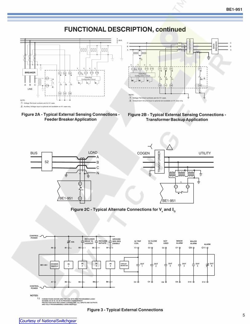
BE1-951
5
Figure 2A - Typical External Sensing Connections -Feeder Breaker Application
FUNCTIONAL DESCRIPTION continued
Figure 2B - Typical External Sensing Connections -Transformer Backup Application
Figure 2C - Typical Alternate Connections for Vx and IG
Figure 3 - Typical External Connections
Courtesy of NationalSwitchgearcom
BE1-951
6
FUNCTIONAL DESCRIPTION continued
Fig
ure
6 -
BE
1-95
1 H
1 R
ear P
anel
Co
nn
ectio
ns
Figure 5 - BE1-951 S1 Rear Panel Connections
Figure 4 - Typical Application Single Line
Based upon pre-programmed logic OC-W-79Not all available protection and control functions are shown
Figure 7 - BE1-951 S1 Double-EndedRear Panel Connections
Courtesy of NationalSwitchgearcom
BE1-951
7
GENERAL SPECIFICATIONS5 Amp CURRENT INPUTS
Continuous rating 20AOne Sec Rating 400ASaturation limit 150ABurden lt10milliohms
1 Amp CURRENT INPUTSContinuous rating 4AOne Sec rating 250ASaturation limit 30ABurden lt22milliohms
PHASE AC VOLTAGE INPUTSContinuous 300V Line to LineOne Sec rating 600V Line to NeutralBurden Less than 1VA 300Vac
AUXILIARY AC VOLTAGE INPUTContinuous 150VOne Sec rating 600VBurden Less than 1VA 150Vac
AD CONVERTERSampling Rate 12cycle adjusted to
input frequency 10-75Hz
POWER SUPPLYOption 1 DC range 35 - 150V
AC range 55 - 135VOption 2 DC range 90 - 300V
AC range 90 - 270VOption 3 DC range 17 - 32V (down
to 8V for momentary dips)Burden 6 watts continuous
8 watts maximum withall outputs energized
TRIP CONTACTSMake and carry 30A (02sec)Continuous 7ABreak 03A DC (LR=004)
CONTROL INPUTSWetting voltage range Same as control power
supply option Low Range High Range
Power Turn-on Turn-on Supply Voltage Voltage
Option Range Burden Range Burden
1) 48125VacVdc 26-38V 13k ohms 69-100V 24k ohms
2) 125250VacVdc 69-100V 25k ohms 138-200V 54k ohms
3) 24Vdc 5-8Vdc 7k ohms NA NA
Control inputs recognize both DC and AC voltages
COMMUNICATION PORTSResponse time lt100mSec for metering
and control functionsBaud rate 300 - 19200
ELECTRICAL ENVIRONMENTbull IEEE C3790-1989 Standard for Relays and Relay
Systems Associated with Electric Power Apparatusbull IEC 255-5 Insulation Test for Electrical Relays
Impulse and Dielectric Strength (2000Vac at 5060Hz)bull IEEE C37901-1989 Standard Surge Withstand Cap-
ability Tests for Relays and Relay Systems Associatedwith Electric Power Apparatus
bull IEC 255-22-1 1MHz Burst Disturbance Tests for Elec-trical Disturbance Tests for Measuring Relays andProtection Equipment
bull EN 61000-4-4 Electrical Fast TransientBurst ImmunityTest
bull EN 61000-4-3 Radiated Radio-frequency Electro-magnetic Field Immunity Test
bull Type tested using a 5-watt hand-held transceiver inthe ranges of 144 and 440MHz with the antennaplaced within 6 inches of the relay
bull IEEE C37903 (Jan 01) Draft Standard ElectrostaticDischarge Tests for Protective Relays
bull EN 61000-4-2 Electrostatic Discharge Immunity Test
MECHANICAL ENVIRONMENTbull Operating temperature range -40degC to 70degC
(-40degF to 158degF)LCD Display is inoperative below -20degC
bull Storage temperature range -40degC to 70degC(-40degF to 158degF)
bull Humidity Qualified to IEC 68-2-38 1st Edition1974 Basic Environmental Test ProceduresPart 2 Test ZAD Composite TemperatureHumidity Cyclic Test
bull Qualified to IEC 255-21-1 (Class 1) Vibration Testsfor Electrical Relays
bull Qualified to IEC 255-21-2 (Class 1) Shock andBump Tests for Electrical Relays
CERTIFICATIONSUL Recognized File E97033CSA Certified File LR23131Gost R Certified POCC USME05B03391DNP 30 IED Certified Subset Level 2 62000 by SUBNET Solutions Inc
CASE SIZEH1 1050W x 347H x 910D with mounting
flanges (85W without mounting flanges)S1 665W x 932H x 951D (includes relay cover)S1 double-ended 665W x 932H x 951D
(includes relay cover)
SHIPPING WEIGHTH1 Approx 10 poundsS1 Approx 112 poundsS1 double-ended 128 pounds
WARRANTY7 years
Courtesy of NationalSwitchgearcom
BE1-951
8
Figure 8A - BESTlogic Function Blocks
Courtesy of NationalSwitchgearcom
BE1-951
9
Figure 8B - BESTlogic Function Blocks
Courtesy of NationalSwitchgearcom
BE1-951
10
PERFORMANCE SPECIFICATIONS
INSTANTANEOUS OVERCURRENT WITHSETTABLE DELAY (50TP 150TP 50TN 150TN50TQ 150TQ)
Pickup 5A CT 05 - 1500A1A CT 01 - 300A
PU time with TD=0000 Sec2 cyc for P N ampG 5 x PU3 cyc for Q 5 x PU
Delay time 0000 - 60 secTime Accuracy plusmn05 or plusmnfrac12 cyc for P and N
plusmn05 or plusmn1 cyc for Q
TIME OVERCURRENT (51P 51N 151N 51Q)Pickup 5A CT 05 - 160A
1A CT 01 - 320ATime dial TD=K=0 - 99 for 46 curve
TD=00 - 99 for all other curvesTime-Current Characteristics
The following expression describes the inversetime current characteristic for each curve
TT = AD + BD + K = Time to trip
MN-C
TR = RD = Time for decaying reset
M2-1
where D = Time dial M = Multiple of PU and A BC N K and R are constants that govern the shapeof each curve The protection engineer can set theconstants for the P (programmable) curve toachieve virtually any characteristic
51P VOLTAGE CONTROL (27R)Control Modes Uncontrolled voltage
controlled voltage restrainedControlRestraint Range 30 - 250VRestrained Mode Characteristic (see below)
ConstantsCurveType
S1
S2
L1
L2
D
M
I1
I2
V1
V2
E1
E2
A
B
C
G
F
46
P
S1 S2 = CO Short Inv IAC Short Inv A = IEC Standard InverseL1 L2 = CO Long Inv IAC Long Inv B = IEC Very InverseD = CO Definite Time C = IEC Extremely InverseM = CO Moderately Inverse G = IEC Long Time InverseI1 I2 = CO Inverse IAC Inverse F = Fixed TimeV1 V2 = CO Very Inv IAC Very Inv 46 = Negative Sequence OvercurrentE1 E2 = CO Ext Inverse IAC Ext Inverse P = Programmable
Constant A is variable for the 46 curve and is determined as necessary based on system full load current setting minimum pickup and K factor settings
DIRECTIONAL CONTROL (ALL OVERCURRENT)Mode Forward Reverse
Nondirectional67P Polarization Positive Sequence wMemory
Negative Sequence67Q Polarization Negative Sequence67N Polarization Selectable any combination
Zero Sequence Voltage(Requires 4W VT)Zero Sequence Current(Requires IG)Negative Sequence
BREAKER FAILURE (BF)Time 50 - 999mSecDropout 5A CT 05A
1A CT 01ATime Accuracy plusmn05 or +1frac14 cyc - frac12 cyc
VOLTSHZ (24)Pickup 05 - 6VHzDelay Time Inverse Squared Curve
DT ETTT = (M-1)2 TR = DR x FST x 100TT = Time to Trip TR = Time to ResetDT = Time Dial Trip DR = Time Dial Reset
Actual VHzM = Pickup VHz ET = Elapsed TimeFST = Full Scale Trip Time (TT)
A B C N K R
02663 003393 1000 12969 0028 05000
00286 002080 1000 09844 0028 00940
56143 218592 1000 1000 0028 15750
23955 000000 1000 03125 0028 78001
04797 021359 1000 15625 0028 08750
03022 012840 1000 05000 0028 17500
89341 017966 1000 20938 0028 90000
02747 01042 1000 04375 0028 08868
54678 010814 1000 20469 0028 55000
44309 00991 1000 19531 0028 58231
77624 002758 1000 20938 0028 77500
49883 00129 1000 20469 0028 47742
001414 000000 1000 00200 0028 20000
14636 000000 1000 10469 0028 32500
82506 000000 1000 20469 0028 80000
121212 000000 1000 1000 0028 29000
00000 100000 0000 00000 0028 10000
0 0 2 0028 100
0 to 600 0 to 25 0 to 1 5 to 25 0028 0 to 30
Courtesy of NationalSwitchgearcom
BE1-951
11
PERFORMANCE SPECIFICATIONS continued
PHASE OVERUNDERVOLTAGE (27P 59P)Mode 1 of 3 2 of 3 3 of 3Pickup 100-300VL-L or 100-300VL-NDelay Time 0050 - 600sec
NEGATIVE SEQUENCE OVERVOLTAGE (47)Pickup 10 - 300VL-NDelay Time 0050 - 600sec
AUXILIARY 3V0 OVERUNDERVOLTAGE(27X 59X 159X)
Mode Fundamental VX 3 phase Residual (3V0)3rd Harmonic VX
Pickup 10 - 150VDelay Time 0050 - 600 Sec
POWER (32)Mode Forward ReversePickup 5A 10 - 6000 Watts 3 ph
1A 10 - 1200 Watts 3 phPickup Accuracy plusmn3Delay Time 0050 - 600 Sec
FREQUENCY (81 181 281 381 481 581)Mode Over UnderPickup 4000 - 7000 HzDelay Time 0000 - 600 SecTime Accuracy plusmn05 or +1 cyc -0 cyc(Min trip time affected by min 3 cyc securitycount)
GENERAL PURPOSE LOGIC TIMERS (62 162)Mode PUDO
1 Shot Non-Retrig1 Shot RetrigIntegratingLatch
T1 and T2 Delay Time 0000 - 9999 SecTime Accuracy plusmn05 or plusmnfrac34 cyc
RECLOSER (79)Mode Power up to close
Power up to lockoutReclose Shots 0 - 4Reclose Reset FailMax Cycle Timers 0100 - 600 SecTime Accuracy plusmn05 or
+1frac34 cyc-0 cyc
CURRENT PICKUP ACCURACY (All 50 and 51)Phase and Ground 5A 2 or 50mA
1A 2 or 10mANeutral and Negative 5A 3 or 75mASequence 1A 3 or 75mA
VOLTAGE PICKUP ACCURACY (All 27 47 and 59)Phase (VL-L or VL-N) plusmn2 or plusmn05VPhase 3V0 and V2 plusmn2 or plusmn05V
DEFINITE TIME ACCURACY UNLESS OTHERWISESTATED (All 27 47 and 59)
Definite Time Accuracy plusmn05 or plusmn1 cyc
SETTING GROUPSSetting Groups 4Control Modes AutomaticCLP
Recloser shotDynamic load or unbalanceExternal Discrete input logicBinary Input Logic
METERINGCurrent Range 5A 05 to 150
1A 01 to 30Current Accuracy plusmn1Phase Voltage Range 3W 0 - 300 VL-L
4W 0 - 300 VL-L
Phase Voltage Accuracy plusmn05 for50VltVL-Llt300V
WattVAR 5A 0 to plusmn75001A 0 to plusmn1500
Watt Accuracy 1 Unity PFVAR Accuracy 1 Zero PFEnergy 0 to plusmn10E12
(FR registers)Frequency 10 - 75HzFrequency Accuracy 001Hz
DEMANDS (IA IB IC IN IQ Fwd Watts Rvs WattsFwd VARs Rvs VARs)
Demand Interval 1 - 60 minDemand Mode Thermal
BREAKER MONITORINGDuty Mode I or I2
Duty Alarm Range 0 - to 100Op Counter Alarm Range 0 - 99999Trip Time Alarm Range 20 - 1000mSec
SYNC CHECK (25)Delta Phase Angle 1 - 45 degreesDelta Voltage Magnitude 1 - 20VDelta Frequency 001 - 050Hz
SYNC CHECK VOLTAGE MONITOR (25VM)Dead Threshold 10 - 150VLive Threshold 10 - 150VDropout Time Delay 0050 - 600secLogic Dead PhaseDead Aux
Dead PhaseLive AuxLive PhaseDead Aux
Two Independent outputs 25VM1 and 25VM2
Courtesy of NationalSwitchgearcom
BE1-951
ORDERINGSAMPLE STYLE NUMBERThe style number identification chart defines the electrical characteristics and operation features included inBE1-951 relays For example if the style number were BE1-951 E3N1H0Y the device would have the following
BE1-951(E) - 5 Amp nominal system with 5 Amp Independent Ground Input(3) - Three phase voltage sensing(N) - Not applicable(1) - 48125VacVdc power supply(H) - Half Rack Case Normally Closed Alarm(0) - ASCII Communications(Y) - 4000 point Load Profile Demand Log
Printed in USAPrinted in USAPrinted in USAPrinted in USAPrinted in USA
STANDARD ACCESSORIES9334818100 Battery Backup Replacement Kit (if U or W is chosen for Option 1)9108551021 Adapter plate to mount an S1 case in a GE S2 or Westinghouse FT-21 cutout9108551022 Adapter plate to mount an S1 case in a Westinghouse FT-32 cutout
9289900017Escutcheon plateto panel mountone H1 relay
9289900016Escutcheon plateto panel mount twodovetailed H1 relays
9289924100Adapter bracket to mountsingle H1 case in 19rdquo rack
9289929100Adapter bracket with cutout forABB FT test switch to mount asingle H1 case in a 19rdquo rack
Figure 9ACover option A
Figure 9BCover option B
Route 143 Box 269 Highland Illinois USA 62249Tel +1 6186542341 Fax +1 6186542351
e-mail infobaslercom
No 1300 North Zhongshan Road Wujiang Economic Development ZoneSuzhou Jiangsu Province - PR China 215200
Tel +86(0)512 6346 1730 Fax +86(0)512 6346 1760e-mail beichinabaslercomwwwbaslercom
PAE Les Pins 67319 Wasselonne Cedex FRANCETel +33 388871010 Fax +33 388870808
e-mail beifrancebaslercom
Courtesy of NationalSwitchgearcom
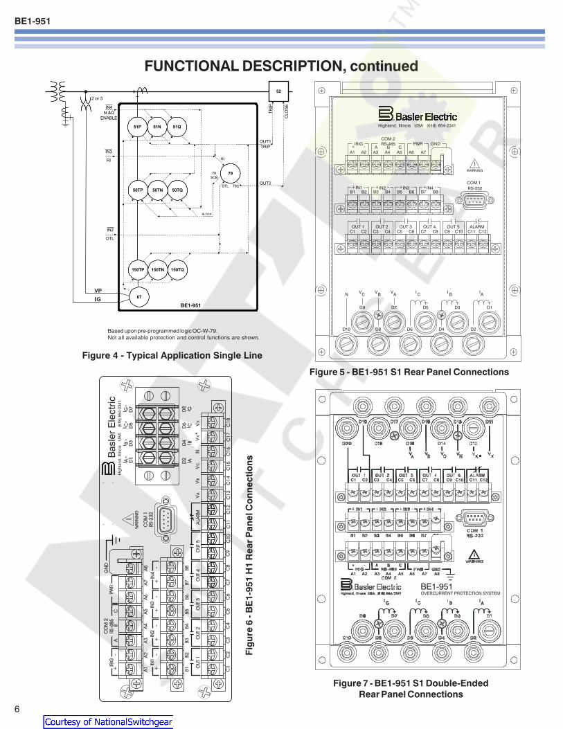
BE1-951
6
FUNCTIONAL DESCRIPTION continued
Fig
ure
6 -
BE
1-95
1 H
1 R
ear P
anel
Co
nn
ectio
ns
Figure 5 - BE1-951 S1 Rear Panel Connections
Figure 4 - Typical Application Single Line
Based upon pre-programmed logic OC-W-79Not all available protection and control functions are shown
Figure 7 - BE1-951 S1 Double-EndedRear Panel Connections
Courtesy of NationalSwitchgearcom
BE1-951
7
GENERAL SPECIFICATIONS5 Amp CURRENT INPUTS
Continuous rating 20AOne Sec Rating 400ASaturation limit 150ABurden lt10milliohms
1 Amp CURRENT INPUTSContinuous rating 4AOne Sec rating 250ASaturation limit 30ABurden lt22milliohms
PHASE AC VOLTAGE INPUTSContinuous 300V Line to LineOne Sec rating 600V Line to NeutralBurden Less than 1VA 300Vac
AUXILIARY AC VOLTAGE INPUTContinuous 150VOne Sec rating 600VBurden Less than 1VA 150Vac
AD CONVERTERSampling Rate 12cycle adjusted to
input frequency 10-75Hz
POWER SUPPLYOption 1 DC range 35 - 150V
AC range 55 - 135VOption 2 DC range 90 - 300V
AC range 90 - 270VOption 3 DC range 17 - 32V (down
to 8V for momentary dips)Burden 6 watts continuous
8 watts maximum withall outputs energized
TRIP CONTACTSMake and carry 30A (02sec)Continuous 7ABreak 03A DC (LR=004)
CONTROL INPUTSWetting voltage range Same as control power
supply option Low Range High Range
Power Turn-on Turn-on Supply Voltage Voltage
Option Range Burden Range Burden
1) 48125VacVdc 26-38V 13k ohms 69-100V 24k ohms
2) 125250VacVdc 69-100V 25k ohms 138-200V 54k ohms
3) 24Vdc 5-8Vdc 7k ohms NA NA
Control inputs recognize both DC and AC voltages
COMMUNICATION PORTSResponse time lt100mSec for metering
and control functionsBaud rate 300 - 19200
ELECTRICAL ENVIRONMENTbull IEEE C3790-1989 Standard for Relays and Relay
Systems Associated with Electric Power Apparatusbull IEC 255-5 Insulation Test for Electrical Relays
Impulse and Dielectric Strength (2000Vac at 5060Hz)bull IEEE C37901-1989 Standard Surge Withstand Cap-
ability Tests for Relays and Relay Systems Associatedwith Electric Power Apparatus
bull IEC 255-22-1 1MHz Burst Disturbance Tests for Elec-trical Disturbance Tests for Measuring Relays andProtection Equipment
bull EN 61000-4-4 Electrical Fast TransientBurst ImmunityTest
bull EN 61000-4-3 Radiated Radio-frequency Electro-magnetic Field Immunity Test
bull Type tested using a 5-watt hand-held transceiver inthe ranges of 144 and 440MHz with the antennaplaced within 6 inches of the relay
bull IEEE C37903 (Jan 01) Draft Standard ElectrostaticDischarge Tests for Protective Relays
bull EN 61000-4-2 Electrostatic Discharge Immunity Test
MECHANICAL ENVIRONMENTbull Operating temperature range -40degC to 70degC
(-40degF to 158degF)LCD Display is inoperative below -20degC
bull Storage temperature range -40degC to 70degC(-40degF to 158degF)
bull Humidity Qualified to IEC 68-2-38 1st Edition1974 Basic Environmental Test ProceduresPart 2 Test ZAD Composite TemperatureHumidity Cyclic Test
bull Qualified to IEC 255-21-1 (Class 1) Vibration Testsfor Electrical Relays
bull Qualified to IEC 255-21-2 (Class 1) Shock andBump Tests for Electrical Relays
CERTIFICATIONSUL Recognized File E97033CSA Certified File LR23131Gost R Certified POCC USME05B03391DNP 30 IED Certified Subset Level 2 62000 by SUBNET Solutions Inc
CASE SIZEH1 1050W x 347H x 910D with mounting
flanges (85W without mounting flanges)S1 665W x 932H x 951D (includes relay cover)S1 double-ended 665W x 932H x 951D
(includes relay cover)
SHIPPING WEIGHTH1 Approx 10 poundsS1 Approx 112 poundsS1 double-ended 128 pounds
WARRANTY7 years
Courtesy of NationalSwitchgearcom
BE1-951
8
Figure 8A - BESTlogic Function Blocks
Courtesy of NationalSwitchgearcom
BE1-951
9
Figure 8B - BESTlogic Function Blocks
Courtesy of NationalSwitchgearcom
BE1-951
10
PERFORMANCE SPECIFICATIONS
INSTANTANEOUS OVERCURRENT WITHSETTABLE DELAY (50TP 150TP 50TN 150TN50TQ 150TQ)
Pickup 5A CT 05 - 1500A1A CT 01 - 300A
PU time with TD=0000 Sec2 cyc for P N ampG 5 x PU3 cyc for Q 5 x PU
Delay time 0000 - 60 secTime Accuracy plusmn05 or plusmnfrac12 cyc for P and N
plusmn05 or plusmn1 cyc for Q
TIME OVERCURRENT (51P 51N 151N 51Q)Pickup 5A CT 05 - 160A
1A CT 01 - 320ATime dial TD=K=0 - 99 for 46 curve
TD=00 - 99 for all other curvesTime-Current Characteristics
The following expression describes the inversetime current characteristic for each curve
TT = AD + BD + K = Time to trip
MN-C
TR = RD = Time for decaying reset
M2-1
where D = Time dial M = Multiple of PU and A BC N K and R are constants that govern the shapeof each curve The protection engineer can set theconstants for the P (programmable) curve toachieve virtually any characteristic
51P VOLTAGE CONTROL (27R)Control Modes Uncontrolled voltage
controlled voltage restrainedControlRestraint Range 30 - 250VRestrained Mode Characteristic (see below)
ConstantsCurveType
S1
S2
L1
L2
D
M
I1
I2
V1
V2
E1
E2
A
B
C
G
F
46
P
S1 S2 = CO Short Inv IAC Short Inv A = IEC Standard InverseL1 L2 = CO Long Inv IAC Long Inv B = IEC Very InverseD = CO Definite Time C = IEC Extremely InverseM = CO Moderately Inverse G = IEC Long Time InverseI1 I2 = CO Inverse IAC Inverse F = Fixed TimeV1 V2 = CO Very Inv IAC Very Inv 46 = Negative Sequence OvercurrentE1 E2 = CO Ext Inverse IAC Ext Inverse P = Programmable
Constant A is variable for the 46 curve and is determined as necessary based on system full load current setting minimum pickup and K factor settings
DIRECTIONAL CONTROL (ALL OVERCURRENT)Mode Forward Reverse
Nondirectional67P Polarization Positive Sequence wMemory
Negative Sequence67Q Polarization Negative Sequence67N Polarization Selectable any combination
Zero Sequence Voltage(Requires 4W VT)Zero Sequence Current(Requires IG)Negative Sequence
BREAKER FAILURE (BF)Time 50 - 999mSecDropout 5A CT 05A
1A CT 01ATime Accuracy plusmn05 or +1frac14 cyc - frac12 cyc
VOLTSHZ (24)Pickup 05 - 6VHzDelay Time Inverse Squared Curve
DT ETTT = (M-1)2 TR = DR x FST x 100TT = Time to Trip TR = Time to ResetDT = Time Dial Trip DR = Time Dial Reset
Actual VHzM = Pickup VHz ET = Elapsed TimeFST = Full Scale Trip Time (TT)
A B C N K R
02663 003393 1000 12969 0028 05000
00286 002080 1000 09844 0028 00940
56143 218592 1000 1000 0028 15750
23955 000000 1000 03125 0028 78001
04797 021359 1000 15625 0028 08750
03022 012840 1000 05000 0028 17500
89341 017966 1000 20938 0028 90000
02747 01042 1000 04375 0028 08868
54678 010814 1000 20469 0028 55000
44309 00991 1000 19531 0028 58231
77624 002758 1000 20938 0028 77500
49883 00129 1000 20469 0028 47742
001414 000000 1000 00200 0028 20000
14636 000000 1000 10469 0028 32500
82506 000000 1000 20469 0028 80000
121212 000000 1000 1000 0028 29000
00000 100000 0000 00000 0028 10000
0 0 2 0028 100
0 to 600 0 to 25 0 to 1 5 to 25 0028 0 to 30
Courtesy of NationalSwitchgearcom
BE1-951
11
PERFORMANCE SPECIFICATIONS continued
PHASE OVERUNDERVOLTAGE (27P 59P)Mode 1 of 3 2 of 3 3 of 3Pickup 100-300VL-L or 100-300VL-NDelay Time 0050 - 600sec
NEGATIVE SEQUENCE OVERVOLTAGE (47)Pickup 10 - 300VL-NDelay Time 0050 - 600sec
AUXILIARY 3V0 OVERUNDERVOLTAGE(27X 59X 159X)
Mode Fundamental VX 3 phase Residual (3V0)3rd Harmonic VX
Pickup 10 - 150VDelay Time 0050 - 600 Sec
POWER (32)Mode Forward ReversePickup 5A 10 - 6000 Watts 3 ph
1A 10 - 1200 Watts 3 phPickup Accuracy plusmn3Delay Time 0050 - 600 Sec
FREQUENCY (81 181 281 381 481 581)Mode Over UnderPickup 4000 - 7000 HzDelay Time 0000 - 600 SecTime Accuracy plusmn05 or +1 cyc -0 cyc(Min trip time affected by min 3 cyc securitycount)
GENERAL PURPOSE LOGIC TIMERS (62 162)Mode PUDO
1 Shot Non-Retrig1 Shot RetrigIntegratingLatch
T1 and T2 Delay Time 0000 - 9999 SecTime Accuracy plusmn05 or plusmnfrac34 cyc
RECLOSER (79)Mode Power up to close
Power up to lockoutReclose Shots 0 - 4Reclose Reset FailMax Cycle Timers 0100 - 600 SecTime Accuracy plusmn05 or
+1frac34 cyc-0 cyc
CURRENT PICKUP ACCURACY (All 50 and 51)Phase and Ground 5A 2 or 50mA
1A 2 or 10mANeutral and Negative 5A 3 or 75mASequence 1A 3 or 75mA
VOLTAGE PICKUP ACCURACY (All 27 47 and 59)Phase (VL-L or VL-N) plusmn2 or plusmn05VPhase 3V0 and V2 plusmn2 or plusmn05V
DEFINITE TIME ACCURACY UNLESS OTHERWISESTATED (All 27 47 and 59)
Definite Time Accuracy plusmn05 or plusmn1 cyc
SETTING GROUPSSetting Groups 4Control Modes AutomaticCLP
Recloser shotDynamic load or unbalanceExternal Discrete input logicBinary Input Logic
METERINGCurrent Range 5A 05 to 150
1A 01 to 30Current Accuracy plusmn1Phase Voltage Range 3W 0 - 300 VL-L
4W 0 - 300 VL-L
Phase Voltage Accuracy plusmn05 for50VltVL-Llt300V
WattVAR 5A 0 to plusmn75001A 0 to plusmn1500
Watt Accuracy 1 Unity PFVAR Accuracy 1 Zero PFEnergy 0 to plusmn10E12
(FR registers)Frequency 10 - 75HzFrequency Accuracy 001Hz
DEMANDS (IA IB IC IN IQ Fwd Watts Rvs WattsFwd VARs Rvs VARs)
Demand Interval 1 - 60 minDemand Mode Thermal
BREAKER MONITORINGDuty Mode I or I2
Duty Alarm Range 0 - to 100Op Counter Alarm Range 0 - 99999Trip Time Alarm Range 20 - 1000mSec
SYNC CHECK (25)Delta Phase Angle 1 - 45 degreesDelta Voltage Magnitude 1 - 20VDelta Frequency 001 - 050Hz
SYNC CHECK VOLTAGE MONITOR (25VM)Dead Threshold 10 - 150VLive Threshold 10 - 150VDropout Time Delay 0050 - 600secLogic Dead PhaseDead Aux
Dead PhaseLive AuxLive PhaseDead Aux
Two Independent outputs 25VM1 and 25VM2
Courtesy of NationalSwitchgearcom
BE1-951
ORDERINGSAMPLE STYLE NUMBERThe style number identification chart defines the electrical characteristics and operation features included inBE1-951 relays For example if the style number were BE1-951 E3N1H0Y the device would have the following
BE1-951(E) - 5 Amp nominal system with 5 Amp Independent Ground Input(3) - Three phase voltage sensing(N) - Not applicable(1) - 48125VacVdc power supply(H) - Half Rack Case Normally Closed Alarm(0) - ASCII Communications(Y) - 4000 point Load Profile Demand Log
Printed in USAPrinted in USAPrinted in USAPrinted in USAPrinted in USA
STANDARD ACCESSORIES9334818100 Battery Backup Replacement Kit (if U or W is chosen for Option 1)9108551021 Adapter plate to mount an S1 case in a GE S2 or Westinghouse FT-21 cutout9108551022 Adapter plate to mount an S1 case in a Westinghouse FT-32 cutout
9289900017Escutcheon plateto panel mountone H1 relay
9289900016Escutcheon plateto panel mount twodovetailed H1 relays
9289924100Adapter bracket to mountsingle H1 case in 19rdquo rack
9289929100Adapter bracket with cutout forABB FT test switch to mount asingle H1 case in a 19rdquo rack
Figure 9ACover option A
Figure 9BCover option B
Route 143 Box 269 Highland Illinois USA 62249Tel +1 6186542341 Fax +1 6186542351
e-mail infobaslercom
No 1300 North Zhongshan Road Wujiang Economic Development ZoneSuzhou Jiangsu Province - PR China 215200
Tel +86(0)512 6346 1730 Fax +86(0)512 6346 1760e-mail beichinabaslercomwwwbaslercom
PAE Les Pins 67319 Wasselonne Cedex FRANCETel +33 388871010 Fax +33 388870808
e-mail beifrancebaslercom
Courtesy of NationalSwitchgearcom
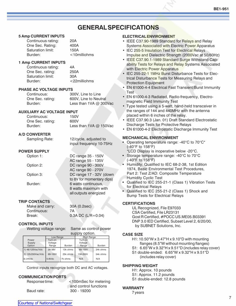
BE1-951
7
GENERAL SPECIFICATIONS5 Amp CURRENT INPUTS
Continuous rating 20AOne Sec Rating 400ASaturation limit 150ABurden lt10milliohms
1 Amp CURRENT INPUTSContinuous rating 4AOne Sec rating 250ASaturation limit 30ABurden lt22milliohms
PHASE AC VOLTAGE INPUTSContinuous 300V Line to LineOne Sec rating 600V Line to NeutralBurden Less than 1VA 300Vac
AUXILIARY AC VOLTAGE INPUTContinuous 150VOne Sec rating 600VBurden Less than 1VA 150Vac
AD CONVERTERSampling Rate 12cycle adjusted to
input frequency 10-75Hz
POWER SUPPLYOption 1 DC range 35 - 150V
AC range 55 - 135VOption 2 DC range 90 - 300V
AC range 90 - 270VOption 3 DC range 17 - 32V (down
to 8V for momentary dips)Burden 6 watts continuous
8 watts maximum withall outputs energized
TRIP CONTACTSMake and carry 30A (02sec)Continuous 7ABreak 03A DC (LR=004)
CONTROL INPUTSWetting voltage range Same as control power
supply option Low Range High Range
Power Turn-on Turn-on Supply Voltage Voltage
Option Range Burden Range Burden
1) 48125VacVdc 26-38V 13k ohms 69-100V 24k ohms
2) 125250VacVdc 69-100V 25k ohms 138-200V 54k ohms
3) 24Vdc 5-8Vdc 7k ohms NA NA
Control inputs recognize both DC and AC voltages
COMMUNICATION PORTSResponse time lt100mSec for metering
and control functionsBaud rate 300 - 19200
ELECTRICAL ENVIRONMENTbull IEEE C3790-1989 Standard for Relays and Relay
Systems Associated with Electric Power Apparatusbull IEC 255-5 Insulation Test for Electrical Relays
Impulse and Dielectric Strength (2000Vac at 5060Hz)bull IEEE C37901-1989 Standard Surge Withstand Cap-
ability Tests for Relays and Relay Systems Associatedwith Electric Power Apparatus
bull IEC 255-22-1 1MHz Burst Disturbance Tests for Elec-trical Disturbance Tests for Measuring Relays andProtection Equipment
bull EN 61000-4-4 Electrical Fast TransientBurst ImmunityTest
bull EN 61000-4-3 Radiated Radio-frequency Electro-magnetic Field Immunity Test
bull Type tested using a 5-watt hand-held transceiver inthe ranges of 144 and 440MHz with the antennaplaced within 6 inches of the relay
bull IEEE C37903 (Jan 01) Draft Standard ElectrostaticDischarge Tests for Protective Relays
bull EN 61000-4-2 Electrostatic Discharge Immunity Test
MECHANICAL ENVIRONMENTbull Operating temperature range -40degC to 70degC
(-40degF to 158degF)LCD Display is inoperative below -20degC
bull Storage temperature range -40degC to 70degC(-40degF to 158degF)
bull Humidity Qualified to IEC 68-2-38 1st Edition1974 Basic Environmental Test ProceduresPart 2 Test ZAD Composite TemperatureHumidity Cyclic Test
bull Qualified to IEC 255-21-1 (Class 1) Vibration Testsfor Electrical Relays
bull Qualified to IEC 255-21-2 (Class 1) Shock andBump Tests for Electrical Relays
CERTIFICATIONSUL Recognized File E97033CSA Certified File LR23131Gost R Certified POCC USME05B03391DNP 30 IED Certified Subset Level 2 62000 by SUBNET Solutions Inc
CASE SIZEH1 1050W x 347H x 910D with mounting
flanges (85W without mounting flanges)S1 665W x 932H x 951D (includes relay cover)S1 double-ended 665W x 932H x 951D
(includes relay cover)
SHIPPING WEIGHTH1 Approx 10 poundsS1 Approx 112 poundsS1 double-ended 128 pounds
WARRANTY7 years
Courtesy of NationalSwitchgearcom
BE1-951
8
Figure 8A - BESTlogic Function Blocks
Courtesy of NationalSwitchgearcom
BE1-951
9
Figure 8B - BESTlogic Function Blocks
Courtesy of NationalSwitchgearcom
BE1-951
10
PERFORMANCE SPECIFICATIONS
INSTANTANEOUS OVERCURRENT WITHSETTABLE DELAY (50TP 150TP 50TN 150TN50TQ 150TQ)
Pickup 5A CT 05 - 1500A1A CT 01 - 300A
PU time with TD=0000 Sec2 cyc for P N ampG 5 x PU3 cyc for Q 5 x PU
Delay time 0000 - 60 secTime Accuracy plusmn05 or plusmnfrac12 cyc for P and N
plusmn05 or plusmn1 cyc for Q
TIME OVERCURRENT (51P 51N 151N 51Q)Pickup 5A CT 05 - 160A
1A CT 01 - 320ATime dial TD=K=0 - 99 for 46 curve
TD=00 - 99 for all other curvesTime-Current Characteristics
The following expression describes the inversetime current characteristic for each curve
TT = AD + BD + K = Time to trip
MN-C
TR = RD = Time for decaying reset
M2-1
where D = Time dial M = Multiple of PU and A BC N K and R are constants that govern the shapeof each curve The protection engineer can set theconstants for the P (programmable) curve toachieve virtually any characteristic
51P VOLTAGE CONTROL (27R)Control Modes Uncontrolled voltage
controlled voltage restrainedControlRestraint Range 30 - 250VRestrained Mode Characteristic (see below)
ConstantsCurveType
S1
S2
L1
L2
D
M
I1
I2
V1
V2
E1
E2
A
B
C
G
F
46
P
S1 S2 = CO Short Inv IAC Short Inv A = IEC Standard InverseL1 L2 = CO Long Inv IAC Long Inv B = IEC Very InverseD = CO Definite Time C = IEC Extremely InverseM = CO Moderately Inverse G = IEC Long Time InverseI1 I2 = CO Inverse IAC Inverse F = Fixed TimeV1 V2 = CO Very Inv IAC Very Inv 46 = Negative Sequence OvercurrentE1 E2 = CO Ext Inverse IAC Ext Inverse P = Programmable
Constant A is variable for the 46 curve and is determined as necessary based on system full load current setting minimum pickup and K factor settings
DIRECTIONAL CONTROL (ALL OVERCURRENT)Mode Forward Reverse
Nondirectional67P Polarization Positive Sequence wMemory
Negative Sequence67Q Polarization Negative Sequence67N Polarization Selectable any combination
Zero Sequence Voltage(Requires 4W VT)Zero Sequence Current(Requires IG)Negative Sequence
BREAKER FAILURE (BF)Time 50 - 999mSecDropout 5A CT 05A
1A CT 01ATime Accuracy plusmn05 or +1frac14 cyc - frac12 cyc
VOLTSHZ (24)Pickup 05 - 6VHzDelay Time Inverse Squared Curve
DT ETTT = (M-1)2 TR = DR x FST x 100TT = Time to Trip TR = Time to ResetDT = Time Dial Trip DR = Time Dial Reset
Actual VHzM = Pickup VHz ET = Elapsed TimeFST = Full Scale Trip Time (TT)
A B C N K R
02663 003393 1000 12969 0028 05000
00286 002080 1000 09844 0028 00940
56143 218592 1000 1000 0028 15750
23955 000000 1000 03125 0028 78001
04797 021359 1000 15625 0028 08750
03022 012840 1000 05000 0028 17500
89341 017966 1000 20938 0028 90000
02747 01042 1000 04375 0028 08868
54678 010814 1000 20469 0028 55000
44309 00991 1000 19531 0028 58231
77624 002758 1000 20938 0028 77500
49883 00129 1000 20469 0028 47742
001414 000000 1000 00200 0028 20000
14636 000000 1000 10469 0028 32500
82506 000000 1000 20469 0028 80000
121212 000000 1000 1000 0028 29000
00000 100000 0000 00000 0028 10000
0 0 2 0028 100
0 to 600 0 to 25 0 to 1 5 to 25 0028 0 to 30
Courtesy of NationalSwitchgearcom
BE1-951
11
PERFORMANCE SPECIFICATIONS continued
PHASE OVERUNDERVOLTAGE (27P 59P)Mode 1 of 3 2 of 3 3 of 3Pickup 100-300VL-L or 100-300VL-NDelay Time 0050 - 600sec
NEGATIVE SEQUENCE OVERVOLTAGE (47)Pickup 10 - 300VL-NDelay Time 0050 - 600sec
AUXILIARY 3V0 OVERUNDERVOLTAGE(27X 59X 159X)
Mode Fundamental VX 3 phase Residual (3V0)3rd Harmonic VX
Pickup 10 - 150VDelay Time 0050 - 600 Sec
POWER (32)Mode Forward ReversePickup 5A 10 - 6000 Watts 3 ph
1A 10 - 1200 Watts 3 phPickup Accuracy plusmn3Delay Time 0050 - 600 Sec
FREQUENCY (81 181 281 381 481 581)Mode Over UnderPickup 4000 - 7000 HzDelay Time 0000 - 600 SecTime Accuracy plusmn05 or +1 cyc -0 cyc(Min trip time affected by min 3 cyc securitycount)
GENERAL PURPOSE LOGIC TIMERS (62 162)Mode PUDO
1 Shot Non-Retrig1 Shot RetrigIntegratingLatch
T1 and T2 Delay Time 0000 - 9999 SecTime Accuracy plusmn05 or plusmnfrac34 cyc
RECLOSER (79)Mode Power up to close
Power up to lockoutReclose Shots 0 - 4Reclose Reset FailMax Cycle Timers 0100 - 600 SecTime Accuracy plusmn05 or
+1frac34 cyc-0 cyc
CURRENT PICKUP ACCURACY (All 50 and 51)Phase and Ground 5A 2 or 50mA
1A 2 or 10mANeutral and Negative 5A 3 or 75mASequence 1A 3 or 75mA
VOLTAGE PICKUP ACCURACY (All 27 47 and 59)Phase (VL-L or VL-N) plusmn2 or plusmn05VPhase 3V0 and V2 plusmn2 or plusmn05V
DEFINITE TIME ACCURACY UNLESS OTHERWISESTATED (All 27 47 and 59)
Definite Time Accuracy plusmn05 or plusmn1 cyc
SETTING GROUPSSetting Groups 4Control Modes AutomaticCLP
Recloser shotDynamic load or unbalanceExternal Discrete input logicBinary Input Logic
METERINGCurrent Range 5A 05 to 150
1A 01 to 30Current Accuracy plusmn1Phase Voltage Range 3W 0 - 300 VL-L
4W 0 - 300 VL-L
Phase Voltage Accuracy plusmn05 for50VltVL-Llt300V
WattVAR 5A 0 to plusmn75001A 0 to plusmn1500
Watt Accuracy 1 Unity PFVAR Accuracy 1 Zero PFEnergy 0 to plusmn10E12
(FR registers)Frequency 10 - 75HzFrequency Accuracy 001Hz
DEMANDS (IA IB IC IN IQ Fwd Watts Rvs WattsFwd VARs Rvs VARs)
Demand Interval 1 - 60 minDemand Mode Thermal
BREAKER MONITORINGDuty Mode I or I2
Duty Alarm Range 0 - to 100Op Counter Alarm Range 0 - 99999Trip Time Alarm Range 20 - 1000mSec
SYNC CHECK (25)Delta Phase Angle 1 - 45 degreesDelta Voltage Magnitude 1 - 20VDelta Frequency 001 - 050Hz
SYNC CHECK VOLTAGE MONITOR (25VM)Dead Threshold 10 - 150VLive Threshold 10 - 150VDropout Time Delay 0050 - 600secLogic Dead PhaseDead Aux
Dead PhaseLive AuxLive PhaseDead Aux
Two Independent outputs 25VM1 and 25VM2
Courtesy of NationalSwitchgearcom
BE1-951
ORDERINGSAMPLE STYLE NUMBERThe style number identification chart defines the electrical characteristics and operation features included inBE1-951 relays For example if the style number were BE1-951 E3N1H0Y the device would have the following
BE1-951(E) - 5 Amp nominal system with 5 Amp Independent Ground Input(3) - Three phase voltage sensing(N) - Not applicable(1) - 48125VacVdc power supply(H) - Half Rack Case Normally Closed Alarm(0) - ASCII Communications(Y) - 4000 point Load Profile Demand Log
Printed in USAPrinted in USAPrinted in USAPrinted in USAPrinted in USA
STANDARD ACCESSORIES9334818100 Battery Backup Replacement Kit (if U or W is chosen for Option 1)9108551021 Adapter plate to mount an S1 case in a GE S2 or Westinghouse FT-21 cutout9108551022 Adapter plate to mount an S1 case in a Westinghouse FT-32 cutout
9289900017Escutcheon plateto panel mountone H1 relay
9289900016Escutcheon plateto panel mount twodovetailed H1 relays
9289924100Adapter bracket to mountsingle H1 case in 19rdquo rack
9289929100Adapter bracket with cutout forABB FT test switch to mount asingle H1 case in a 19rdquo rack
Figure 9ACover option A
Figure 9BCover option B
Route 143 Box 269 Highland Illinois USA 62249Tel +1 6186542341 Fax +1 6186542351
e-mail infobaslercom
No 1300 North Zhongshan Road Wujiang Economic Development ZoneSuzhou Jiangsu Province - PR China 215200
Tel +86(0)512 6346 1730 Fax +86(0)512 6346 1760e-mail beichinabaslercomwwwbaslercom
PAE Les Pins 67319 Wasselonne Cedex FRANCETel +33 388871010 Fax +33 388870808
e-mail beifrancebaslercom
Courtesy of NationalSwitchgearcom
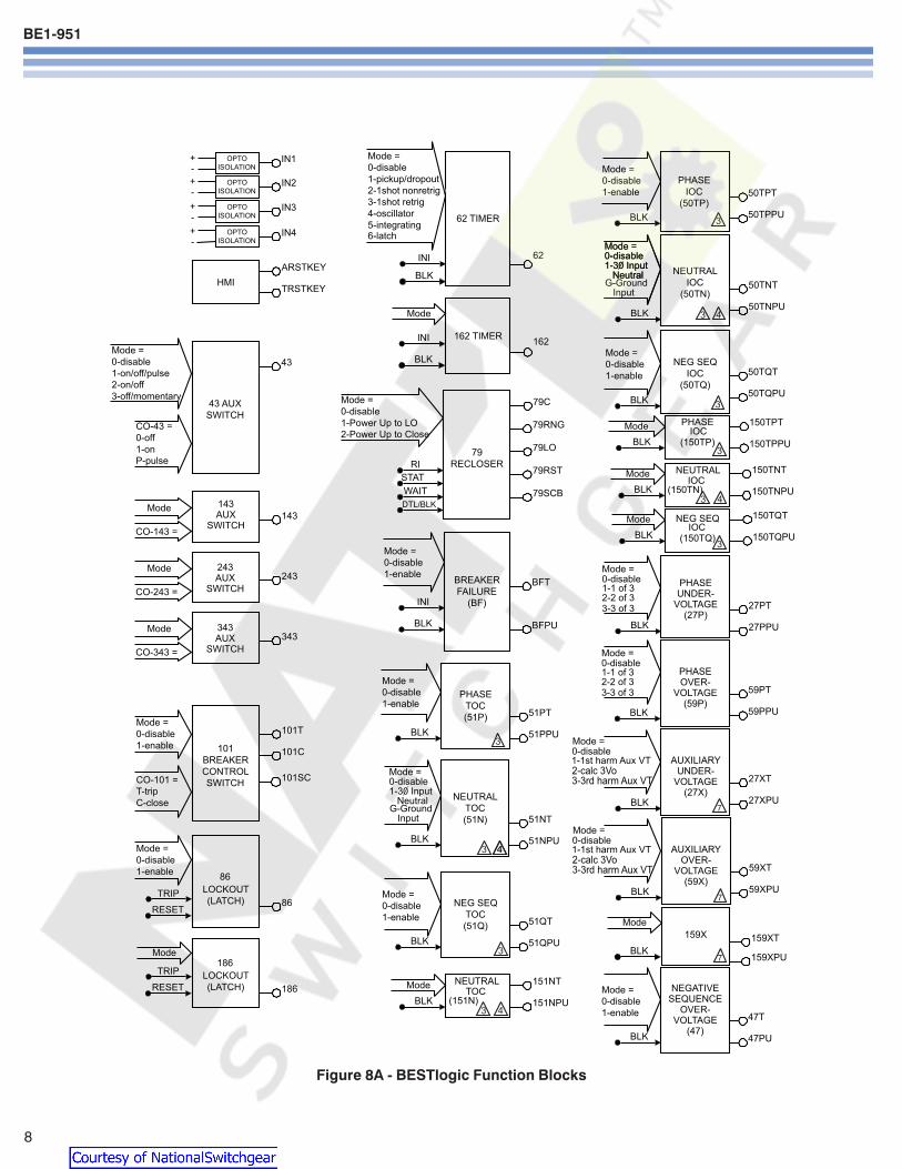
BE1-951
8
Figure 8A - BESTlogic Function Blocks
Courtesy of NationalSwitchgearcom
BE1-951
9
Figure 8B - BESTlogic Function Blocks
Courtesy of NationalSwitchgearcom
BE1-951
10
PERFORMANCE SPECIFICATIONS
INSTANTANEOUS OVERCURRENT WITHSETTABLE DELAY (50TP 150TP 50TN 150TN50TQ 150TQ)
Pickup 5A CT 05 - 1500A1A CT 01 - 300A
PU time with TD=0000 Sec2 cyc for P N ampG 5 x PU3 cyc for Q 5 x PU
Delay time 0000 - 60 secTime Accuracy plusmn05 or plusmnfrac12 cyc for P and N
plusmn05 or plusmn1 cyc for Q
TIME OVERCURRENT (51P 51N 151N 51Q)Pickup 5A CT 05 - 160A
1A CT 01 - 320ATime dial TD=K=0 - 99 for 46 curve
TD=00 - 99 for all other curvesTime-Current Characteristics
The following expression describes the inversetime current characteristic for each curve
TT = AD + BD + K = Time to trip
MN-C
TR = RD = Time for decaying reset
M2-1
where D = Time dial M = Multiple of PU and A BC N K and R are constants that govern the shapeof each curve The protection engineer can set theconstants for the P (programmable) curve toachieve virtually any characteristic
51P VOLTAGE CONTROL (27R)Control Modes Uncontrolled voltage
controlled voltage restrainedControlRestraint Range 30 - 250VRestrained Mode Characteristic (see below)
ConstantsCurveType
S1
S2
L1
L2
D
M
I1
I2
V1
V2
E1
E2
A
B
C
G
F
46
P
S1 S2 = CO Short Inv IAC Short Inv A = IEC Standard InverseL1 L2 = CO Long Inv IAC Long Inv B = IEC Very InverseD = CO Definite Time C = IEC Extremely InverseM = CO Moderately Inverse G = IEC Long Time InverseI1 I2 = CO Inverse IAC Inverse F = Fixed TimeV1 V2 = CO Very Inv IAC Very Inv 46 = Negative Sequence OvercurrentE1 E2 = CO Ext Inverse IAC Ext Inverse P = Programmable
Constant A is variable for the 46 curve and is determined as necessary based on system full load current setting minimum pickup and K factor settings
DIRECTIONAL CONTROL (ALL OVERCURRENT)Mode Forward Reverse
Nondirectional67P Polarization Positive Sequence wMemory
Negative Sequence67Q Polarization Negative Sequence67N Polarization Selectable any combination
Zero Sequence Voltage(Requires 4W VT)Zero Sequence Current(Requires IG)Negative Sequence
BREAKER FAILURE (BF)Time 50 - 999mSecDropout 5A CT 05A
1A CT 01ATime Accuracy plusmn05 or +1frac14 cyc - frac12 cyc
VOLTSHZ (24)Pickup 05 - 6VHzDelay Time Inverse Squared Curve
DT ETTT = (M-1)2 TR = DR x FST x 100TT = Time to Trip TR = Time to ResetDT = Time Dial Trip DR = Time Dial Reset
Actual VHzM = Pickup VHz ET = Elapsed TimeFST = Full Scale Trip Time (TT)
A B C N K R
02663 003393 1000 12969 0028 05000
00286 002080 1000 09844 0028 00940
56143 218592 1000 1000 0028 15750
23955 000000 1000 03125 0028 78001
04797 021359 1000 15625 0028 08750
03022 012840 1000 05000 0028 17500
89341 017966 1000 20938 0028 90000
02747 01042 1000 04375 0028 08868
54678 010814 1000 20469 0028 55000
44309 00991 1000 19531 0028 58231
77624 002758 1000 20938 0028 77500
49883 00129 1000 20469 0028 47742
001414 000000 1000 00200 0028 20000
14636 000000 1000 10469 0028 32500
82506 000000 1000 20469 0028 80000
121212 000000 1000 1000 0028 29000
00000 100000 0000 00000 0028 10000
0 0 2 0028 100
0 to 600 0 to 25 0 to 1 5 to 25 0028 0 to 30
Courtesy of NationalSwitchgearcom
BE1-951
11
PERFORMANCE SPECIFICATIONS continued
PHASE OVERUNDERVOLTAGE (27P 59P)Mode 1 of 3 2 of 3 3 of 3Pickup 100-300VL-L or 100-300VL-NDelay Time 0050 - 600sec
NEGATIVE SEQUENCE OVERVOLTAGE (47)Pickup 10 - 300VL-NDelay Time 0050 - 600sec
AUXILIARY 3V0 OVERUNDERVOLTAGE(27X 59X 159X)
Mode Fundamental VX 3 phase Residual (3V0)3rd Harmonic VX
Pickup 10 - 150VDelay Time 0050 - 600 Sec
POWER (32)Mode Forward ReversePickup 5A 10 - 6000 Watts 3 ph
1A 10 - 1200 Watts 3 phPickup Accuracy plusmn3Delay Time 0050 - 600 Sec
FREQUENCY (81 181 281 381 481 581)Mode Over UnderPickup 4000 - 7000 HzDelay Time 0000 - 600 SecTime Accuracy plusmn05 or +1 cyc -0 cyc(Min trip time affected by min 3 cyc securitycount)
GENERAL PURPOSE LOGIC TIMERS (62 162)Mode PUDO
1 Shot Non-Retrig1 Shot RetrigIntegratingLatch
T1 and T2 Delay Time 0000 - 9999 SecTime Accuracy plusmn05 or plusmnfrac34 cyc
RECLOSER (79)Mode Power up to close
Power up to lockoutReclose Shots 0 - 4Reclose Reset FailMax Cycle Timers 0100 - 600 SecTime Accuracy plusmn05 or
+1frac34 cyc-0 cyc
CURRENT PICKUP ACCURACY (All 50 and 51)Phase and Ground 5A 2 or 50mA
1A 2 or 10mANeutral and Negative 5A 3 or 75mASequence 1A 3 or 75mA
VOLTAGE PICKUP ACCURACY (All 27 47 and 59)Phase (VL-L or VL-N) plusmn2 or plusmn05VPhase 3V0 and V2 plusmn2 or plusmn05V
DEFINITE TIME ACCURACY UNLESS OTHERWISESTATED (All 27 47 and 59)
Definite Time Accuracy plusmn05 or plusmn1 cyc
SETTING GROUPSSetting Groups 4Control Modes AutomaticCLP
Recloser shotDynamic load or unbalanceExternal Discrete input logicBinary Input Logic
METERINGCurrent Range 5A 05 to 150
1A 01 to 30Current Accuracy plusmn1Phase Voltage Range 3W 0 - 300 VL-L
4W 0 - 300 VL-L
Phase Voltage Accuracy plusmn05 for50VltVL-Llt300V
WattVAR 5A 0 to plusmn75001A 0 to plusmn1500
Watt Accuracy 1 Unity PFVAR Accuracy 1 Zero PFEnergy 0 to plusmn10E12
(FR registers)Frequency 10 - 75HzFrequency Accuracy 001Hz
DEMANDS (IA IB IC IN IQ Fwd Watts Rvs WattsFwd VARs Rvs VARs)
Demand Interval 1 - 60 minDemand Mode Thermal
BREAKER MONITORINGDuty Mode I or I2
Duty Alarm Range 0 - to 100Op Counter Alarm Range 0 - 99999Trip Time Alarm Range 20 - 1000mSec
SYNC CHECK (25)Delta Phase Angle 1 - 45 degreesDelta Voltage Magnitude 1 - 20VDelta Frequency 001 - 050Hz
SYNC CHECK VOLTAGE MONITOR (25VM)Dead Threshold 10 - 150VLive Threshold 10 - 150VDropout Time Delay 0050 - 600secLogic Dead PhaseDead Aux
Dead PhaseLive AuxLive PhaseDead Aux
Two Independent outputs 25VM1 and 25VM2
Courtesy of NationalSwitchgearcom
BE1-951
ORDERINGSAMPLE STYLE NUMBERThe style number identification chart defines the electrical characteristics and operation features included inBE1-951 relays For example if the style number were BE1-951 E3N1H0Y the device would have the following
BE1-951(E) - 5 Amp nominal system with 5 Amp Independent Ground Input(3) - Three phase voltage sensing(N) - Not applicable(1) - 48125VacVdc power supply(H) - Half Rack Case Normally Closed Alarm(0) - ASCII Communications(Y) - 4000 point Load Profile Demand Log
Printed in USAPrinted in USAPrinted in USAPrinted in USAPrinted in USA
STANDARD ACCESSORIES9334818100 Battery Backup Replacement Kit (if U or W is chosen for Option 1)9108551021 Adapter plate to mount an S1 case in a GE S2 or Westinghouse FT-21 cutout9108551022 Adapter plate to mount an S1 case in a Westinghouse FT-32 cutout
9289900017Escutcheon plateto panel mountone H1 relay
9289900016Escutcheon plateto panel mount twodovetailed H1 relays
9289924100Adapter bracket to mountsingle H1 case in 19rdquo rack
9289929100Adapter bracket with cutout forABB FT test switch to mount asingle H1 case in a 19rdquo rack
Figure 9ACover option A
Figure 9BCover option B
Route 143 Box 269 Highland Illinois USA 62249Tel +1 6186542341 Fax +1 6186542351
e-mail infobaslercom
No 1300 North Zhongshan Road Wujiang Economic Development ZoneSuzhou Jiangsu Province - PR China 215200
Tel +86(0)512 6346 1730 Fax +86(0)512 6346 1760e-mail beichinabaslercomwwwbaslercom
PAE Les Pins 67319 Wasselonne Cedex FRANCETel +33 388871010 Fax +33 388870808
e-mail beifrancebaslercom
Courtesy of NationalSwitchgearcom
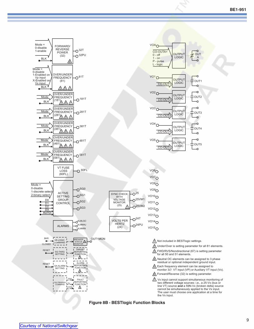
BE1-951
9
Figure 8B - BESTlogic Function Blocks
Courtesy of NationalSwitchgearcom
BE1-951
10
PERFORMANCE SPECIFICATIONS
INSTANTANEOUS OVERCURRENT WITHSETTABLE DELAY (50TP 150TP 50TN 150TN50TQ 150TQ)
Pickup 5A CT 05 - 1500A1A CT 01 - 300A
PU time with TD=0000 Sec2 cyc for P N ampG 5 x PU3 cyc for Q 5 x PU
Delay time 0000 - 60 secTime Accuracy plusmn05 or plusmnfrac12 cyc for P and N
plusmn05 or plusmn1 cyc for Q
TIME OVERCURRENT (51P 51N 151N 51Q)Pickup 5A CT 05 - 160A
1A CT 01 - 320ATime dial TD=K=0 - 99 for 46 curve
TD=00 - 99 for all other curvesTime-Current Characteristics
The following expression describes the inversetime current characteristic for each curve
TT = AD + BD + K = Time to trip
MN-C
TR = RD = Time for decaying reset
M2-1
where D = Time dial M = Multiple of PU and A BC N K and R are constants that govern the shapeof each curve The protection engineer can set theconstants for the P (programmable) curve toachieve virtually any characteristic
51P VOLTAGE CONTROL (27R)Control Modes Uncontrolled voltage
controlled voltage restrainedControlRestraint Range 30 - 250VRestrained Mode Characteristic (see below)
ConstantsCurveType
S1
S2
L1
L2
D
M
I1
I2
V1
V2
E1
E2
A
B
C
G
F
46
P
S1 S2 = CO Short Inv IAC Short Inv A = IEC Standard InverseL1 L2 = CO Long Inv IAC Long Inv B = IEC Very InverseD = CO Definite Time C = IEC Extremely InverseM = CO Moderately Inverse G = IEC Long Time InverseI1 I2 = CO Inverse IAC Inverse F = Fixed TimeV1 V2 = CO Very Inv IAC Very Inv 46 = Negative Sequence OvercurrentE1 E2 = CO Ext Inverse IAC Ext Inverse P = Programmable
Constant A is variable for the 46 curve and is determined as necessary based on system full load current setting minimum pickup and K factor settings
DIRECTIONAL CONTROL (ALL OVERCURRENT)Mode Forward Reverse
Nondirectional67P Polarization Positive Sequence wMemory
Negative Sequence67Q Polarization Negative Sequence67N Polarization Selectable any combination
Zero Sequence Voltage(Requires 4W VT)Zero Sequence Current(Requires IG)Negative Sequence
BREAKER FAILURE (BF)Time 50 - 999mSecDropout 5A CT 05A
1A CT 01ATime Accuracy plusmn05 or +1frac14 cyc - frac12 cyc
VOLTSHZ (24)Pickup 05 - 6VHzDelay Time Inverse Squared Curve
DT ETTT = (M-1)2 TR = DR x FST x 100TT = Time to Trip TR = Time to ResetDT = Time Dial Trip DR = Time Dial Reset
Actual VHzM = Pickup VHz ET = Elapsed TimeFST = Full Scale Trip Time (TT)
A B C N K R
02663 003393 1000 12969 0028 05000
00286 002080 1000 09844 0028 00940
56143 218592 1000 1000 0028 15750
23955 000000 1000 03125 0028 78001
04797 021359 1000 15625 0028 08750
03022 012840 1000 05000 0028 17500
89341 017966 1000 20938 0028 90000
02747 01042 1000 04375 0028 08868
54678 010814 1000 20469 0028 55000
44309 00991 1000 19531 0028 58231
77624 002758 1000 20938 0028 77500
49883 00129 1000 20469 0028 47742
001414 000000 1000 00200 0028 20000
14636 000000 1000 10469 0028 32500
82506 000000 1000 20469 0028 80000
121212 000000 1000 1000 0028 29000
00000 100000 0000 00000 0028 10000
0 0 2 0028 100
0 to 600 0 to 25 0 to 1 5 to 25 0028 0 to 30
Courtesy of NationalSwitchgearcom
BE1-951
11
PERFORMANCE SPECIFICATIONS continued
PHASE OVERUNDERVOLTAGE (27P 59P)Mode 1 of 3 2 of 3 3 of 3Pickup 100-300VL-L or 100-300VL-NDelay Time 0050 - 600sec
NEGATIVE SEQUENCE OVERVOLTAGE (47)Pickup 10 - 300VL-NDelay Time 0050 - 600sec
AUXILIARY 3V0 OVERUNDERVOLTAGE(27X 59X 159X)
Mode Fundamental VX 3 phase Residual (3V0)3rd Harmonic VX
Pickup 10 - 150VDelay Time 0050 - 600 Sec
POWER (32)Mode Forward ReversePickup 5A 10 - 6000 Watts 3 ph
1A 10 - 1200 Watts 3 phPickup Accuracy plusmn3Delay Time 0050 - 600 Sec
FREQUENCY (81 181 281 381 481 581)Mode Over UnderPickup 4000 - 7000 HzDelay Time 0000 - 600 SecTime Accuracy plusmn05 or +1 cyc -0 cyc(Min trip time affected by min 3 cyc securitycount)
GENERAL PURPOSE LOGIC TIMERS (62 162)Mode PUDO
1 Shot Non-Retrig1 Shot RetrigIntegratingLatch
T1 and T2 Delay Time 0000 - 9999 SecTime Accuracy plusmn05 or plusmnfrac34 cyc
RECLOSER (79)Mode Power up to close
Power up to lockoutReclose Shots 0 - 4Reclose Reset FailMax Cycle Timers 0100 - 600 SecTime Accuracy plusmn05 or
+1frac34 cyc-0 cyc
CURRENT PICKUP ACCURACY (All 50 and 51)Phase and Ground 5A 2 or 50mA
1A 2 or 10mANeutral and Negative 5A 3 or 75mASequence 1A 3 or 75mA
VOLTAGE PICKUP ACCURACY (All 27 47 and 59)Phase (VL-L or VL-N) plusmn2 or plusmn05VPhase 3V0 and V2 plusmn2 or plusmn05V
DEFINITE TIME ACCURACY UNLESS OTHERWISESTATED (All 27 47 and 59)
Definite Time Accuracy plusmn05 or plusmn1 cyc
SETTING GROUPSSetting Groups 4Control Modes AutomaticCLP
Recloser shotDynamic load or unbalanceExternal Discrete input logicBinary Input Logic
METERINGCurrent Range 5A 05 to 150
1A 01 to 30Current Accuracy plusmn1Phase Voltage Range 3W 0 - 300 VL-L
4W 0 - 300 VL-L
Phase Voltage Accuracy plusmn05 for50VltVL-Llt300V
WattVAR 5A 0 to plusmn75001A 0 to plusmn1500
Watt Accuracy 1 Unity PFVAR Accuracy 1 Zero PFEnergy 0 to plusmn10E12
(FR registers)Frequency 10 - 75HzFrequency Accuracy 001Hz
DEMANDS (IA IB IC IN IQ Fwd Watts Rvs WattsFwd VARs Rvs VARs)
Demand Interval 1 - 60 minDemand Mode Thermal
BREAKER MONITORINGDuty Mode I or I2
Duty Alarm Range 0 - to 100Op Counter Alarm Range 0 - 99999Trip Time Alarm Range 20 - 1000mSec
SYNC CHECK (25)Delta Phase Angle 1 - 45 degreesDelta Voltage Magnitude 1 - 20VDelta Frequency 001 - 050Hz
SYNC CHECK VOLTAGE MONITOR (25VM)Dead Threshold 10 - 150VLive Threshold 10 - 150VDropout Time Delay 0050 - 600secLogic Dead PhaseDead Aux
Dead PhaseLive AuxLive PhaseDead Aux
Two Independent outputs 25VM1 and 25VM2
Courtesy of NationalSwitchgearcom
BE1-951
ORDERINGSAMPLE STYLE NUMBERThe style number identification chart defines the electrical characteristics and operation features included inBE1-951 relays For example if the style number were BE1-951 E3N1H0Y the device would have the following
BE1-951(E) - 5 Amp nominal system with 5 Amp Independent Ground Input(3) - Three phase voltage sensing(N) - Not applicable(1) - 48125VacVdc power supply(H) - Half Rack Case Normally Closed Alarm(0) - ASCII Communications(Y) - 4000 point Load Profile Demand Log
Printed in USAPrinted in USAPrinted in USAPrinted in USAPrinted in USA
STANDARD ACCESSORIES9334818100 Battery Backup Replacement Kit (if U or W is chosen for Option 1)9108551021 Adapter plate to mount an S1 case in a GE S2 or Westinghouse FT-21 cutout9108551022 Adapter plate to mount an S1 case in a Westinghouse FT-32 cutout
9289900017Escutcheon plateto panel mountone H1 relay
9289900016Escutcheon plateto panel mount twodovetailed H1 relays
9289924100Adapter bracket to mountsingle H1 case in 19rdquo rack
9289929100Adapter bracket with cutout forABB FT test switch to mount asingle H1 case in a 19rdquo rack
Figure 9ACover option A
Figure 9BCover option B
Route 143 Box 269 Highland Illinois USA 62249Tel +1 6186542341 Fax +1 6186542351
e-mail infobaslercom
No 1300 North Zhongshan Road Wujiang Economic Development ZoneSuzhou Jiangsu Province - PR China 215200
Tel +86(0)512 6346 1730 Fax +86(0)512 6346 1760e-mail beichinabaslercomwwwbaslercom
PAE Les Pins 67319 Wasselonne Cedex FRANCETel +33 388871010 Fax +33 388870808
e-mail beifrancebaslercom
Courtesy of NationalSwitchgearcom
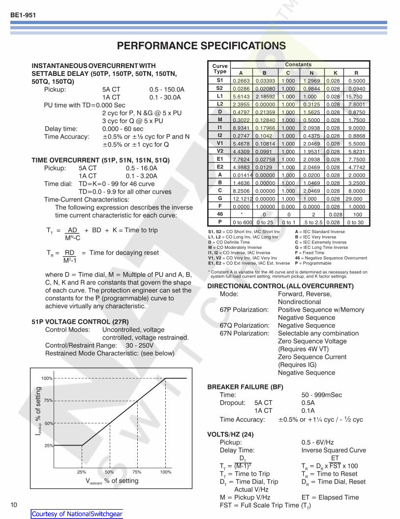
BE1-951
10
PERFORMANCE SPECIFICATIONS
INSTANTANEOUS OVERCURRENT WITHSETTABLE DELAY (50TP 150TP 50TN 150TN50TQ 150TQ)
Pickup 5A CT 05 - 1500A1A CT 01 - 300A
PU time with TD=0000 Sec2 cyc for P N ampG 5 x PU3 cyc for Q 5 x PU
Delay time 0000 - 60 secTime Accuracy plusmn05 or plusmnfrac12 cyc for P and N
plusmn05 or plusmn1 cyc for Q
TIME OVERCURRENT (51P 51N 151N 51Q)Pickup 5A CT 05 - 160A
1A CT 01 - 320ATime dial TD=K=0 - 99 for 46 curve
TD=00 - 99 for all other curvesTime-Current Characteristics
The following expression describes the inversetime current characteristic for each curve
TT = AD + BD + K = Time to trip
MN-C
TR = RD = Time for decaying reset
M2-1
where D = Time dial M = Multiple of PU and A BC N K and R are constants that govern the shapeof each curve The protection engineer can set theconstants for the P (programmable) curve toachieve virtually any characteristic
51P VOLTAGE CONTROL (27R)Control Modes Uncontrolled voltage
controlled voltage restrainedControlRestraint Range 30 - 250VRestrained Mode Characteristic (see below)
ConstantsCurveType
S1
S2
L1
L2
D
M
I1
I2
V1
V2
E1
E2
A
B
C
G
F
46
P
S1 S2 = CO Short Inv IAC Short Inv A = IEC Standard InverseL1 L2 = CO Long Inv IAC Long Inv B = IEC Very InverseD = CO Definite Time C = IEC Extremely InverseM = CO Moderately Inverse G = IEC Long Time InverseI1 I2 = CO Inverse IAC Inverse F = Fixed TimeV1 V2 = CO Very Inv IAC Very Inv 46 = Negative Sequence OvercurrentE1 E2 = CO Ext Inverse IAC Ext Inverse P = Programmable
Constant A is variable for the 46 curve and is determined as necessary based on system full load current setting minimum pickup and K factor settings
DIRECTIONAL CONTROL (ALL OVERCURRENT)Mode Forward Reverse
Nondirectional67P Polarization Positive Sequence wMemory
Negative Sequence67Q Polarization Negative Sequence67N Polarization Selectable any combination
Zero Sequence Voltage(Requires 4W VT)Zero Sequence Current(Requires IG)Negative Sequence
BREAKER FAILURE (BF)Time 50 - 999mSecDropout 5A CT 05A
1A CT 01ATime Accuracy plusmn05 or +1frac14 cyc - frac12 cyc
VOLTSHZ (24)Pickup 05 - 6VHzDelay Time Inverse Squared Curve
DT ETTT = (M-1)2 TR = DR x FST x 100TT = Time to Trip TR = Time to ResetDT = Time Dial Trip DR = Time Dial Reset
Actual VHzM = Pickup VHz ET = Elapsed TimeFST = Full Scale Trip Time (TT)
A B C N K R
02663 003393 1000 12969 0028 05000
00286 002080 1000 09844 0028 00940
56143 218592 1000 1000 0028 15750
23955 000000 1000 03125 0028 78001
04797 021359 1000 15625 0028 08750
03022 012840 1000 05000 0028 17500
89341 017966 1000 20938 0028 90000
02747 01042 1000 04375 0028 08868
54678 010814 1000 20469 0028 55000
44309 00991 1000 19531 0028 58231
77624 002758 1000 20938 0028 77500
49883 00129 1000 20469 0028 47742
001414 000000 1000 00200 0028 20000
14636 000000 1000 10469 0028 32500
82506 000000 1000 20469 0028 80000
121212 000000 1000 1000 0028 29000
00000 100000 0000 00000 0028 10000
0 0 2 0028 100
0 to 600 0 to 25 0 to 1 5 to 25 0028 0 to 30
Courtesy of NationalSwitchgearcom
BE1-951
11
PERFORMANCE SPECIFICATIONS continued
PHASE OVERUNDERVOLTAGE (27P 59P)Mode 1 of 3 2 of 3 3 of 3Pickup 100-300VL-L or 100-300VL-NDelay Time 0050 - 600sec
NEGATIVE SEQUENCE OVERVOLTAGE (47)Pickup 10 - 300VL-NDelay Time 0050 - 600sec
AUXILIARY 3V0 OVERUNDERVOLTAGE(27X 59X 159X)
Mode Fundamental VX 3 phase Residual (3V0)3rd Harmonic VX
Pickup 10 - 150VDelay Time 0050 - 600 Sec
POWER (32)Mode Forward ReversePickup 5A 10 - 6000 Watts 3 ph
1A 10 - 1200 Watts 3 phPickup Accuracy plusmn3Delay Time 0050 - 600 Sec
FREQUENCY (81 181 281 381 481 581)Mode Over UnderPickup 4000 - 7000 HzDelay Time 0000 - 600 SecTime Accuracy plusmn05 or +1 cyc -0 cyc(Min trip time affected by min 3 cyc securitycount)
GENERAL PURPOSE LOGIC TIMERS (62 162)Mode PUDO
1 Shot Non-Retrig1 Shot RetrigIntegratingLatch
T1 and T2 Delay Time 0000 - 9999 SecTime Accuracy plusmn05 or plusmnfrac34 cyc
RECLOSER (79)Mode Power up to close
Power up to lockoutReclose Shots 0 - 4Reclose Reset FailMax Cycle Timers 0100 - 600 SecTime Accuracy plusmn05 or
+1frac34 cyc-0 cyc
CURRENT PICKUP ACCURACY (All 50 and 51)Phase and Ground 5A 2 or 50mA
1A 2 or 10mANeutral and Negative 5A 3 or 75mASequence 1A 3 or 75mA
VOLTAGE PICKUP ACCURACY (All 27 47 and 59)Phase (VL-L or VL-N) plusmn2 or plusmn05VPhase 3V0 and V2 plusmn2 or plusmn05V
DEFINITE TIME ACCURACY UNLESS OTHERWISESTATED (All 27 47 and 59)
Definite Time Accuracy plusmn05 or plusmn1 cyc
SETTING GROUPSSetting Groups 4Control Modes AutomaticCLP
Recloser shotDynamic load or unbalanceExternal Discrete input logicBinary Input Logic
METERINGCurrent Range 5A 05 to 150
1A 01 to 30Current Accuracy plusmn1Phase Voltage Range 3W 0 - 300 VL-L
4W 0 - 300 VL-L
Phase Voltage Accuracy plusmn05 for50VltVL-Llt300V
WattVAR 5A 0 to plusmn75001A 0 to plusmn1500
Watt Accuracy 1 Unity PFVAR Accuracy 1 Zero PFEnergy 0 to plusmn10E12
(FR registers)Frequency 10 - 75HzFrequency Accuracy 001Hz
DEMANDS (IA IB IC IN IQ Fwd Watts Rvs WattsFwd VARs Rvs VARs)
Demand Interval 1 - 60 minDemand Mode Thermal
BREAKER MONITORINGDuty Mode I or I2
Duty Alarm Range 0 - to 100Op Counter Alarm Range 0 - 99999Trip Time Alarm Range 20 - 1000mSec
SYNC CHECK (25)Delta Phase Angle 1 - 45 degreesDelta Voltage Magnitude 1 - 20VDelta Frequency 001 - 050Hz
SYNC CHECK VOLTAGE MONITOR (25VM)Dead Threshold 10 - 150VLive Threshold 10 - 150VDropout Time Delay 0050 - 600secLogic Dead PhaseDead Aux
Dead PhaseLive AuxLive PhaseDead Aux
Two Independent outputs 25VM1 and 25VM2
Courtesy of NationalSwitchgearcom
BE1-951
ORDERINGSAMPLE STYLE NUMBERThe style number identification chart defines the electrical characteristics and operation features included inBE1-951 relays For example if the style number were BE1-951 E3N1H0Y the device would have the following
BE1-951(E) - 5 Amp nominal system with 5 Amp Independent Ground Input(3) - Three phase voltage sensing(N) - Not applicable(1) - 48125VacVdc power supply(H) - Half Rack Case Normally Closed Alarm(0) - ASCII Communications(Y) - 4000 point Load Profile Demand Log
Printed in USAPrinted in USAPrinted in USAPrinted in USAPrinted in USA
STANDARD ACCESSORIES9334818100 Battery Backup Replacement Kit (if U or W is chosen for Option 1)9108551021 Adapter plate to mount an S1 case in a GE S2 or Westinghouse FT-21 cutout9108551022 Adapter plate to mount an S1 case in a Westinghouse FT-32 cutout
9289900017Escutcheon plateto panel mountone H1 relay
9289900016Escutcheon plateto panel mount twodovetailed H1 relays
9289924100Adapter bracket to mountsingle H1 case in 19rdquo rack
9289929100Adapter bracket with cutout forABB FT test switch to mount asingle H1 case in a 19rdquo rack
Figure 9ACover option A
Figure 9BCover option B
Route 143 Box 269 Highland Illinois USA 62249Tel +1 6186542341 Fax +1 6186542351
e-mail infobaslercom
No 1300 North Zhongshan Road Wujiang Economic Development ZoneSuzhou Jiangsu Province - PR China 215200
Tel +86(0)512 6346 1730 Fax +86(0)512 6346 1760e-mail beichinabaslercomwwwbaslercom
PAE Les Pins 67319 Wasselonne Cedex FRANCETel +33 388871010 Fax +33 388870808
e-mail beifrancebaslercom
Courtesy of NationalSwitchgearcom
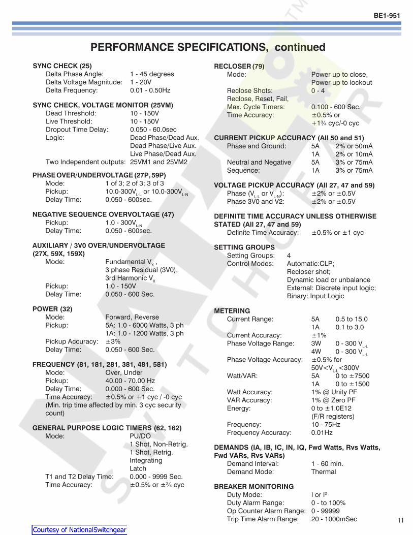
BE1-951
11
PERFORMANCE SPECIFICATIONS continued
PHASE OVERUNDERVOLTAGE (27P 59P)Mode 1 of 3 2 of 3 3 of 3Pickup 100-300VL-L or 100-300VL-NDelay Time 0050 - 600sec
NEGATIVE SEQUENCE OVERVOLTAGE (47)Pickup 10 - 300VL-NDelay Time 0050 - 600sec
AUXILIARY 3V0 OVERUNDERVOLTAGE(27X 59X 159X)
Mode Fundamental VX 3 phase Residual (3V0)3rd Harmonic VX
Pickup 10 - 150VDelay Time 0050 - 600 Sec
POWER (32)Mode Forward ReversePickup 5A 10 - 6000 Watts 3 ph
1A 10 - 1200 Watts 3 phPickup Accuracy plusmn3Delay Time 0050 - 600 Sec
FREQUENCY (81 181 281 381 481 581)Mode Over UnderPickup 4000 - 7000 HzDelay Time 0000 - 600 SecTime Accuracy plusmn05 or +1 cyc -0 cyc(Min trip time affected by min 3 cyc securitycount)
GENERAL PURPOSE LOGIC TIMERS (62 162)Mode PUDO
1 Shot Non-Retrig1 Shot RetrigIntegratingLatch
T1 and T2 Delay Time 0000 - 9999 SecTime Accuracy plusmn05 or plusmnfrac34 cyc
RECLOSER (79)Mode Power up to close
Power up to lockoutReclose Shots 0 - 4Reclose Reset FailMax Cycle Timers 0100 - 600 SecTime Accuracy plusmn05 or
+1frac34 cyc-0 cyc
CURRENT PICKUP ACCURACY (All 50 and 51)Phase and Ground 5A 2 or 50mA
1A 2 or 10mANeutral and Negative 5A 3 or 75mASequence 1A 3 or 75mA
VOLTAGE PICKUP ACCURACY (All 27 47 and 59)Phase (VL-L or VL-N) plusmn2 or plusmn05VPhase 3V0 and V2 plusmn2 or plusmn05V
DEFINITE TIME ACCURACY UNLESS OTHERWISESTATED (All 27 47 and 59)
Definite Time Accuracy plusmn05 or plusmn1 cyc
SETTING GROUPSSetting Groups 4Control Modes AutomaticCLP
Recloser shotDynamic load or unbalanceExternal Discrete input logicBinary Input Logic
METERINGCurrent Range 5A 05 to 150
1A 01 to 30Current Accuracy plusmn1Phase Voltage Range 3W 0 - 300 VL-L
4W 0 - 300 VL-L
Phase Voltage Accuracy plusmn05 for50VltVL-Llt300V
WattVAR 5A 0 to plusmn75001A 0 to plusmn1500
Watt Accuracy 1 Unity PFVAR Accuracy 1 Zero PFEnergy 0 to plusmn10E12
(FR registers)Frequency 10 - 75HzFrequency Accuracy 001Hz
DEMANDS (IA IB IC IN IQ Fwd Watts Rvs WattsFwd VARs Rvs VARs)
Demand Interval 1 - 60 minDemand Mode Thermal
BREAKER MONITORINGDuty Mode I or I2
Duty Alarm Range 0 - to 100Op Counter Alarm Range 0 - 99999Trip Time Alarm Range 20 - 1000mSec
SYNC CHECK (25)Delta Phase Angle 1 - 45 degreesDelta Voltage Magnitude 1 - 20VDelta Frequency 001 - 050Hz
SYNC CHECK VOLTAGE MONITOR (25VM)Dead Threshold 10 - 150VLive Threshold 10 - 150VDropout Time Delay 0050 - 600secLogic Dead PhaseDead Aux
Dead PhaseLive AuxLive PhaseDead Aux
Two Independent outputs 25VM1 and 25VM2
Courtesy of NationalSwitchgearcom
BE1-951
ORDERINGSAMPLE STYLE NUMBERThe style number identification chart defines the electrical characteristics and operation features included inBE1-951 relays For example if the style number were BE1-951 E3N1H0Y the device would have the following
BE1-951(E) - 5 Amp nominal system with 5 Amp Independent Ground Input(3) - Three phase voltage sensing(N) - Not applicable(1) - 48125VacVdc power supply(H) - Half Rack Case Normally Closed Alarm(0) - ASCII Communications(Y) - 4000 point Load Profile Demand Log
Printed in USAPrinted in USAPrinted in USAPrinted in USAPrinted in USA
STANDARD ACCESSORIES9334818100 Battery Backup Replacement Kit (if U or W is chosen for Option 1)9108551021 Adapter plate to mount an S1 case in a GE S2 or Westinghouse FT-21 cutout9108551022 Adapter plate to mount an S1 case in a Westinghouse FT-32 cutout
9289900017Escutcheon plateto panel mountone H1 relay
9289900016Escutcheon plateto panel mount twodovetailed H1 relays
9289924100Adapter bracket to mountsingle H1 case in 19rdquo rack
9289929100Adapter bracket with cutout forABB FT test switch to mount asingle H1 case in a 19rdquo rack
Figure 9ACover option A
Figure 9BCover option B
Route 143 Box 269 Highland Illinois USA 62249Tel +1 6186542341 Fax +1 6186542351
e-mail infobaslercom
No 1300 North Zhongshan Road Wujiang Economic Development ZoneSuzhou Jiangsu Province - PR China 215200
Tel +86(0)512 6346 1730 Fax +86(0)512 6346 1760e-mail beichinabaslercomwwwbaslercom
PAE Les Pins 67319 Wasselonne Cedex FRANCETel +33 388871010 Fax +33 388870808
e-mail beifrancebaslercom
Courtesy of NationalSwitchgearcom
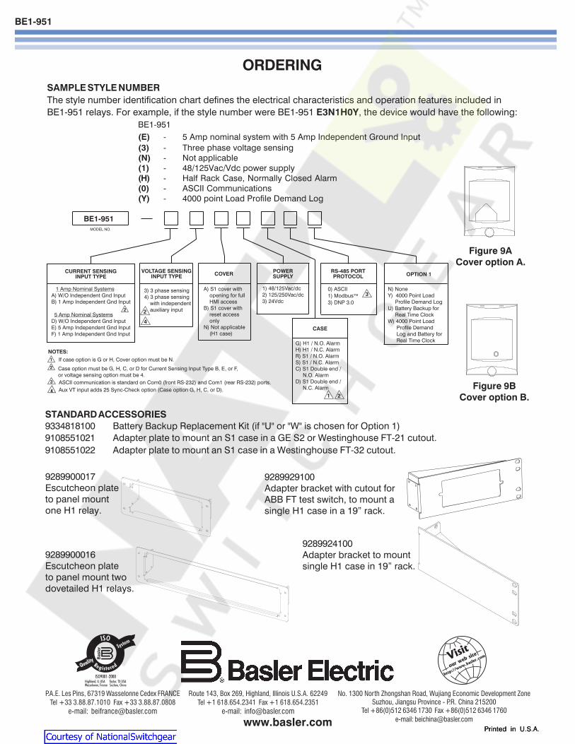
BE1-951
ORDERINGSAMPLE STYLE NUMBERThe style number identification chart defines the electrical characteristics and operation features included inBE1-951 relays For example if the style number were BE1-951 E3N1H0Y the device would have the following
BE1-951(E) - 5 Amp nominal system with 5 Amp Independent Ground Input(3) - Three phase voltage sensing(N) - Not applicable(1) - 48125VacVdc power supply(H) - Half Rack Case Normally Closed Alarm(0) - ASCII Communications(Y) - 4000 point Load Profile Demand Log
Printed in USAPrinted in USAPrinted in USAPrinted in USAPrinted in USA
STANDARD ACCESSORIES9334818100 Battery Backup Replacement Kit (if U or W is chosen for Option 1)9108551021 Adapter plate to mount an S1 case in a GE S2 or Westinghouse FT-21 cutout9108551022 Adapter plate to mount an S1 case in a Westinghouse FT-32 cutout
9289900017Escutcheon plateto panel mountone H1 relay
9289900016Escutcheon plateto panel mount twodovetailed H1 relays
9289924100Adapter bracket to mountsingle H1 case in 19rdquo rack
9289929100Adapter bracket with cutout forABB FT test switch to mount asingle H1 case in a 19rdquo rack
Figure 9ACover option A
Figure 9BCover option B
Route 143 Box 269 Highland Illinois USA 62249Tel +1 6186542341 Fax +1 6186542351
e-mail infobaslercom
No 1300 North Zhongshan Road Wujiang Economic Development ZoneSuzhou Jiangsu Province - PR China 215200
Tel +86(0)512 6346 1730 Fax +86(0)512 6346 1760e-mail beichinabaslercomwwwbaslercom
PAE Les Pins 67319 Wasselonne Cedex FRANCETel +33 388871010 Fax +33 388870808
e-mail beifrancebaslercom
Courtesy of NationalSwitchgearcom
Related Documents


