,,- .. , ' ' ·- 1a 6;1 .2.7·2D Installation/Maintenance Instructions Low-Voltage Power Circuit Breakers Type K-3000, K-4000 K·-30005, K·-4000S, K-3000M, K-4000M 3000 and 4000 Amperes 600 Volts , . ABB Power Distribution, Inc. Circuit Breaker Division ., _jl 1111 ' ,.,1,11 ASEA BROWN BOVE!Rl.

Welcome message from author
This document is posted to help you gain knowledge. Please leave a comment to let me know what you think about it! Share it to your friends and learn new things together.
Transcript

,,-.. , ' ' ·-
1a 6;1 .2.7·2D
Installation/Maintenance Instructions Low-Voltage
Power Circuit Breakers
Type K-3000, K-4000 K·-30005, K·-4000S, K-3000M, K-4000M
3000 and 4000 Amperes 600 Volts
, .
ABB Power Distribution, Inc. Circuit Breaker Division
.,
_jl 1111 ' ,.,1,11 ASEA BROWN BOVE!Rl.
Courtesy of NationalSwitchgear.com
11::1 0.-1..:.r-;w Page 2 ,,1111
ABEA BROWN BOVERI
TABLE OF CONTENTS
PAGE
INTRODUCTION ........................................................................ 3 LUBRICATION ......................................................................... 15 RECEIVING AND STORAGE .................................................... 3 DIELECTRIC TESTS ............................................................... ·15 BASIC HANDLING AND INSTUCTIONS .................................. 3 ELECTRICAL CHARACTERISTICS ............................... : ....... 17 CIRCUIT BREAKER OPERATION AND RATING .................... 3 RENEWAL PARTS .................................................................. 17 CLOSING SPRING OPERATION ....•.......•..............................•.. 3 , MICRO Power Sh le Id (MPS) ................................................... 18 ESCUTCHEON OPERATING FEATURES ................................ 3 Protective Elements ............................................................ 18
Circuit Breaker Nameplate .................................................. 5 Ampere Range Selector ..................................................... 18 Manual Trip Buttcm .............................................................. 5 Targets ................................................................................. 19 Circuit Breaker "OPEN" or "CLOSED" Indicator .............. 5 Long· Time ........................................................................ 19 Automatic Trip Indicator ..................................................... 5 Short· Time ....................................................................... 19 Automatic Trip Alarm Contacts .......................................... 5 lnstaneous ....................................................................... 20 Automatic Trip Lockout Devlce .......................................... 5 Ground ............................................................................. 20 Padlocking Device ............................................................... 5 Self-Monitoring ................................................................ 20 Closing Spring Charge Indicator ....................................... 5 Making Settings ............................................................... 20 Motor Disconnect Switch .................................................... 5 Testing ................................................................................. 20 Electrical Close Push Button .: ........................................... 6 PROCEDURES FOR FIELD TEST ON KLINE Manual Close Lever ............................................................. 6 CIRCUIT BREAKERS .......................................................... 21 Racking Mechanism ............................................................ 6 MPS SOLID STATE SYSTEM TEST ................................... 21
OPERATION OF DEVICES ........................................................ 6 PRIMARY CURRENT TESTING .......................................... 21 Eloctro-Mechanlcal OVCT Device ...................................... 6 INSTANEOUS THRESHOLD TEST ..................................... 21 Control Relay ................... , ................................................... 7 LONG· TIME DELAY TEST .................................................. 21 Auxiliary Switches ............................................................... 8 SHORT· TIME DELAY TEST ................................................ 22 Undervoltage Trip Device ................................................... 8 GROUND TRIP DELAY TEST ............................................. 22
INSTALLATION ......................................................................... 9 FIELD REPAIR INSTRUCTIONS ............................................. 23 Checking Circuit Breaker Operatlo.n·ln Test Position ...... 9 Manual Closing Operation ............ :• .. : .................................. 9
MAGLATCH PRETRAVEL ADJUSTMENT ............................. 24 LUBRICATION ......................................................................... 24
CIRCUIT BREAKER REMOVAL ............................................... 9 PERIODIC MAINTENANCE INSPECTION .............................. 1 O
Arc Chutes ......................................................................... 1 o Insulation Structure ........................................................... 10 Contacts ............................................................................. 1 O Contact Pitting ................................................................... 10 Contact Pressure Check and Adjustment ....................... 1 o Manual Slow Close to Check Contact Pressure ............. 11 Operating Mechanism ....................................................... 11 Primary Trip Latch ............................................................. 13 Tripper Bar Adjustment ................................... ; ................ 13 Electro-Mechanical OVCT Device Adjustments ............. 14 Armature Trip Travel Adjustment .................................... 14 Solid State OVCT Device Settings ................................... ·15
Courtesy of NationalSwitchgear.com

,,1111 ASEA BROWN BOVERI
INTRODUCTION These instructions apply to the type K-3000 and K-4000, K-30008 and K-40008 circuit breakers; 3000 and 4000 ampere ac continuous current rating respectively. The type K-3000 and K-4000 are equipped with electromechanical overcurrent trip devices, whereas the type K-30008 and K-40008 Incorporate the solid state overcurrent trip devices. A K-30008 circuit breaker is shown on the front cover of this bulletin. The K-3000 and K-4000 circuit breakers can be furnished with two or three poles for de or ac operation. K-30008 and K-40008 circuit breakers are only furnished for three pole ac operation. All circuit breakers can be furnished as drawout or stationary mounted and are available as manually or electrically operated, and with electrical control devices available in various ac and de voltage combinations. Many optional features are also available. An electrically operated,,drawout type circuit breaker is shown in Figure ·1, with a typical schematic diagram shown in Figure 2. These instructions should be read thoroughly before handling, installing and/or operating the circuit breal<er.
RECEIVING AND STOl~AGE Immediately upon receipt of the circuit breakers, examine the cartons to determine if any damage or loss was sustained during transit. If injury P,r.'rough handling is evident, file a damage claim at once with the carrier and promptly notify the nearest District Office. The Company is not responsible for damage of goods after delivery to the carrier. However, the Company will lend assistance if notified of claims. Unpacl< the circuit breakers as soon as possible after receipt. If unpacking is delayed, difficulty may be experienced in making a claim for damages not evident upon receipt. Use care in unpacking in order to avoid damaging any of the circuit breaker parts. Check the contents of each carton against the packing list before discarding any packing material. If any shortage of material is discovered, promptly notify the nearest District Office. Information specifying the purchase order number, carton number and part numbers of the damaged or missing parts should accompany the claim. Circuit breakers should be installed in their permanent location as soon as possible. (See Basic Handling below). If the breakers are not to be placed in service for some time, it is advisable to provide adequate means of protection.
RU Uo ~ • .t:,,f'".GU
Page 3
This may be done by i<eeping the breaker in Its original carton, covering with waterproof paper and sealing to prevent infiltration of dirt. Where conditions of high humidity prevail, the use of heaters is recommended.
BASIC HANDLING INSTRUCTIONS Once the circuit breaker has been unbolted and removed from its shipping carton, it should be turned to the upright position and placed on a flat surface to avoid damage to brnaker parts. For safety, all handling in this position should utilize the lifting yoke (20) shown in Figure 1.
CIRCUIT BREAKER OPERATION CIRCUIT BREAKER RATING The K-3000/K-30008 and K-4000/K-40008 circuit breal<' ers are designed to carry a maximum ac continuous current of 3000 amperes and 4000 amperes respectively. Exceeding these ratings may raise the temperature ofthe breakers beyond their design limit and thus affect the life of the breaker. Thus, any long-time pickup setting exceeding 100% of the frame size is to be used only for coordination, not for carrying increased continuous current.
CLOSING SPRING OPERATION The two closing springs supply the power that closes the circuit breaker and also charge the two opening springs during the closing operation. The closing springs are charged by a motor in the electrically operated breaker and charged by hand in the manually operated breaker; however, In either type, the springs are charged the same amount and when charged, the spring energy is available to close the breaker, thus referred to as "stored energy". The closing springs are normally charged when the breaker is opened. If charged after closing, (optional) the breaker may be opened and then reclosed without recharging the springs. In drawout breakers, the closing springs are automatically discharged when the breaker is moved from the disconnected to the withdrawn position (shown in Figure 1). This prevents accidental discharge.
ESCUTCHEON OPERATING FEATUBES Manually and electrically operated circuit breakers are provided with an extendible escutcheon face plate. This escutcheon provides a central area for the controls which are mounted directly on the circuit breaker. The controls for manually operated circuit breakers, Figure 1, included In the escutcheon face plate are: (25) a nameplate giving the various ratings assigned to the particular
[.. . -·- ----···----······-··---- ................................... , ............ -- ........................................... --................... ·--·-................... --.. ----···------··----·9 These insructions do not purport to cover all details or variations in equipment nor to provide contingency to be met in connection with instulation, operation, or maintenace. Should further information be desired or should particular problems arise which are not covered sufficiently for the purchaser's purposes, the matter should be referred to the nearest District Office. -·-----··---------·-------··--···----·--·-------------------·------------··-----·---------------... -----.------·--------·--··--
Courtesy of NationalSwitchgear.com

11::1 0.1.;:,,..;.:u
Page 4
19 _______ ,
12 ------
5--J 23 -6----" 7 ___ J
14 -----· 8 --------9 ------10---
22 ----·---··----
1. Arc Chute 2. Arc Chute Retainer Molding 3. Arc Chute Mounting Screw
* 4. Shutter
* 5. Visual Indicator for Breaker "Closed" or "Otloned 11
6. Manual Close Laver
7. Manual Charging Lover
8. Manual Trip Button
9. Automatic Trip l'ndicator 10. Motor Disconnect Switch
11. Spring Hetainer Brackat 21. 12. Manual Charge Handle 22. 13. Hacking Crank 23. 14. Closing Spring Charge Indicator 24. 15. Orawout Lever 25. 16. Racking Cam Rollers 26. 17. Racking Crank Opening 27. 18. Wheels
* 19. Shutter Lock Screw llnsartad in Shutter)
20. Lifting Yoko
Fig. 1 -Typical Electrically Operated, Drawout Type 1(-3000 Circuit Breaker
IPtllll ASEA BROWN BOVERI
2
24
16
18 27
21
Closing Spring Charging Motor Electrical Close Button Locking Hasp
Auxiliary Switch Nameplate Plata l·li0ged Track Extensions
'Not Visible in This View
)
Courtesy of NationalSwitchgear.com

.,, •••• ASEA BROWN BOVERI
type of circuit breaker, (12) the manual charging handle, (8) the manual trip button, (5) the "OPEN" and "CLOSED" position indicator, (9) the automatic trip indicator with optional facilities for alarm indication and for lockout, (23) a means for padlocking the circuit breaker in the "CONNECTED," "TEST" or "DISCONNECTED" positions, and (14) closing spring charging indicator. The controls for the electrically operated circuit breakers, Figure 1, are the sarne as the manually operated circuit breakers except the charging handle (12) is removed and stored for maintenance use, and the presence of (10) rnotor disconnect switch for the motor electrical circuit and (22) electrical close push button switch . The manually and electrically operated drawout circuit breaker escutcheon also contains the racking crank opening (17) and interlocking drawout lever (15). A self-aligning plate, immediately behind the escutcheon face plate, is used to exclude dust from the circuit breaker compartment. On drawout type circuit breakers, the es·· cutcheon face will protrude through the front door of the compartment when the circuit breaker is in the "TEST" and "DISCONNECTED"pbsitions. In these positions, the dustplate still functions to exclude dust.
Circuit Breaker Nameplate (Figure 1, Item 25) The circuit breaker nameplate contains information regarding (1) the manufacturer's name and address, (2) type of circuit breaker design, (3) serial number of circuit breaker, (4) continuous current rating .of frame size, (5) short circuit current rating at rated voltages, (6) frequency, (7) short time current.
Manual Charging Handle (Figure 1, Item 12) The manual charging handle is a T-·shaped lever used to charge the closing springs by pumping approximately ten times.
Manual Trip Button (Figure 1, Item 8) The manual trip button, when pushed, trips the circuit breaker to "OPEN."
Circuit Breaker "OPEN" or "CLOSED" Indicator (Figure 1, Item 5) Tt1is indicator shows the physical position of t11e circuit breaker contacts.
Automatic Trip Indicator (Figure 1, Item 9) (Not including undervoltage, alarm switch or lockout) The automatic trip indicator is provided as standard equipment on the K-line'" circuit breakers and is used to indicate the operation of 1110 overcurrent trip device. This device is an indicator only and does not prevent the circuit breaker reclosing. Upon an overcurrent trip operation, the indicator protrudes from the front plate approximately 1/2 inch.
Page 5
The automatic trip indicator should be reset after each trip indication by pushing back into its normal latch position. The operator should investigate the cause of tripping before resetting the automatic trip indicator and subsequently reclosing the circuit breaker after an outage which results in an operation of the indicator.
Automatic Trip Alarm Contacts (Mand Reset) (Figure 1, Item 9) An alarm switch for remote electrical indication, which is optional, shows when automatic tripping has occurred, This is accomplished by adding a precision snap switch to the automatic trip indicator assembly. The automatic trip indicator actuates the roller on the alarm switch which In turn causes a normally open contact to close and a normally closed contact to open on overcurrent trip. The alarm contact is manually reset by pushing the trip indicator (9) back into its normal position.
Automatic Trip Lockout (Hand Reset) (Figure 1, Item 9) An additional device (which is also optional) may be added to thH automatic trip indicator assembly device which serves to mechanically prevent reclosing the circuit breaker after an automatic trip operation. When the trip indicator Is pushed in, the circuit breaker mechanism can then be operated to close the circuit breaker contacts.
Padlocking Device (Figure 1, Item 23) All K-line circuit breakers are equipped with means of padlocking the circuit breaker mechanism in a trip-free position. This is accomplished by the use of a locking plate to maintain the manual trip button in a tripping direction when the locking plate is held forward by one or more padlocks. To obtain the condition for padlocking the circuit breaker in the open position, the manual trip button Is pushed inward. Then the padlock plate is pulled out andthe padlock inserted into the vertical slot. In this position, the mechanism is maintained trip free and the contact arm cannot be moved to the closed position. On circuit breakers equipped with drawout mechanism, the padlocking device is associated with the drawout interlocking mechanism so that the circuit breal<er cannot be moved from any of its three basic drawout positions of "CONNECTED," "TEST" or "DISCONNECTED" with the padlocking in effect.
Closing Spring Charge Indicator (Figure 1, Item 14) Under normal operating conditions, the closing springs are automatically charged after each tripping operation. However, there are occasions when the springs will be in a discharged state. Therefore, it is desirable that means be available to indicate the charged or uncharged condition of the closing springs. This is accomplished by a visual indicator seen through an aperture in the escutcheon plate, The indicator is marked "CHARGED" and "UNCHARGED."
Courtesy of NationalSwitchgear.com

IB 6.1.2.7·2D Page 6
Motor Disconnect Switch (Figure 1, Item 10) The motor disconnect switch Is a double pole, single-throw toggle type switch connected In series with the charging motor circuit and is used to disconnect the motor from the voltage source. This sw:tch is used (1), when it is desirable to prevent automatic recharging of the closing springs just prior to tal<lng the circuit breaker out of service for maintenance and (2), for control wiring dielectric test. The motor must be disconnected for the control wiring dielectric test and subsequently tested at 540 V ac or 760 V de.
Electrical. Close Push Button (Figure 1, Item 22) The electrical close push button Is used to electrically close the circuit breaker from the escutcheon. This contact is connected in series with the latch release coll. Energizing the latch release coil allows the charged springs to close the circuit breaker.
• Manual Close Lever (Figure 1, Item 6) The manual close lever is provided on all circuit breakers to . provide a safe means of closing the breaker without control power. The lever is provided with a ring to which a lanyard should be attached for closing the breaker at a safe distance.
Racking Mechanism ( Drawout Bre.aker) The racking mechanism is used to fi\ove the circuit breaker to any one of Its three positlons-·"CONNECTED," "TEST" or "DISCONNECTED." All of these positions are attainable with the cubicle door closed or opened. The breaker can be closed only when the drawout lever ('15, Figure 1) is up. When up, the racking crank (13, Figure 1) cannot be turned. The circuit breaker must be in the "OPEN" position before lever ('15, Figure 1) can be pushed down. In order to move the circuit breaker from one position to another, the lever must be pushed down and the crank turned; once turning begins, the lever will stay down until another position is reached and the lever will snap up, preventing additional turning, until the lever Is again pushed down. When the padlocking device is locked, the lever (15) is locked in the up postlon preventing movement of the racl<lng mechanism. Figure 1 shows the breaker in the fully withdrawn position. There are two sets of indicator lines on the left side of the breaker to show breaker position. One set is visible with the switchboard door closed, the other visible when the door is open.
OPERATION OF DEVICES Electro-Mechanlcal Overcurrent Trip Devices Type K· 3000 and K·4000 Circuit Breakers (Figures ·1 o and ·11) (A) Type OD-300 General Purpose Overcurrent Trip De· vice. The type OD-300 overcurrent trip device, for general
,,1111· ASF.A BROWN BOVF.RI
purpose applications, provides long-time delay tripping on moderate overcurrents which are above the long-time pickup setting; and Instantaneous tripping on fault currents, above the Instantaneous trip setting. This device must be properly set to provide adequate protection for an electrical system. Three adjustment screws on the bottom of the device provide Independent control of the long-time pickup, instantaneous pickup and amount of time delay. The nameplate of this device shows the setting of these adjustments and the range of settings which are available. For information on the time-current characteristics of this device, request a copy of TD-6693. (B) Type OD-400 Selective Overcurrent Trip Device. The type OD-400 overcurrent trip device, for selective tripping applications, provides long-time delay and short-time delay tripping. Independent adjustment of both pickup and time delay is provided for both types of tripping. The nameplate of this device shows the settings which are available. For Information on the time-current characteristics of this de .. vice, request a copy of TD-6694. (C) See Table 1 for complete list of Electro-Mechanical overcurrent trip devices available.
Power Shleld"M Solid State Overcurrent Trip Devices Type K-3000S and K·4000S Circuit Breakers (See Figure 12) This device includes the power supply sensors, overcurrent sensors, Power Shield solid state logic assembly, magnetic latch and the interconnecting wiring. Each phase of the circuit breaker has a power supply sensor and overcurrent sensor. The trip elements that are available are: long-time delay, instantaneous, short-time delay and ground fault. On a 3-phase 4-wire system, an additional remote sensor, mounted in the neutral bus, is required for complete ground fault protection. The logic assembly Is mounted near the front of the circuit breaker and with the cubicle door open the overcurrent control panel Is readily accessible. This device must be properly set, as required by individual circuit conditions, to · provide adequate protection for an electrical system, The movable plugs on the control panel provide independent control of the long-time, short-time, instantaneous and ground fault pickup and amount of time delay. The overcurrent device, with the exception of ground fault, will trip at the value of the AMPERE TAP setting times the plug setting of the various pickup elements. The ground fault trip value will be the plug setting value times 100, as indicated on the nameplate. (A) Type SS-3. This trip device is for general purpose application. It provides long-time delay tripping on moder· ate overcurrents, which are above the long-time pickup settings, and instantareous tripping on fault currents above Ifie instantaneous trip setting. For Information on the time· current characteristics of this device, request a copy of TD·
Courtesy of NationalSwitchgear.com

. "'~1111 ASEA BROWN BOVERI
6966 (TD-9001 '). copy of TD-6968 (TD-9005').
IB 6:1.2."1·20 Page 7
(B) Type SS-4 Selective Overcurrent Trip Device. This trip device, for selective tripping application provides long-time delay and short-time delay tripping. For information on the time-current characteristics of this device, request a copy of TD-6967 (TD .. 9002'),
( E) See Table 1 A for a complete list of standard Solid State overcurrent trip devices.
(C) Type SS-5 Trlple-Selectlve Overcurrent Trip Device. This device includes the trip elements found in both the SS-3 and SS-4; I.e., long-time delay, short-time delay, and instantaneous tripping. For information on the time-current characteristics of this device, request a copy of TD-6967 (TD-9002'). (D) The above three solid state overcurrent trip devices are available with ground fault protection and are designated by the types SS-3G, SS-4G and ss .. sG. For Information on the time current characteristics of this feature, request a
Control Relay This device is contained in the black Insulated molding, 3" X 5" X 6" approximate, located at the lower front of .the mechanism and is used on all electrically operated mechanisms. The 52Y coll, and contacts 52Y/1,52Y/2 are connected as shown in the schematic diagram, Figure 2. The purpose of this device is to require that, if the remote or local close contacts are closed, resulting in the charging springs discharging, the close contacts must first be released (opened) before the breaker can be reclosed. This prevents closing the breaker more than one time unless the close contacts are first released.
rnoLE I
STANDARD ELECTRO•MECHANICAL OVERCURRENT TRIP DEVICES
- --Overcurront Tri~ Element Tlme .. Curront
Device Long .. Shor t .. Inst an .. Ch1irpotorltitlo
'""• TI 111e TI me ~anoous Curve
00·300 x x !0;660 3
00·400 x x 10·6694
00·500 x x x TD•6696
00·600 x x T0-6695
oo- mo x Nona 00•800 - x None
OD·.900 x x TU·6699 -· x !0·6699 oo-~
NOTE: 00 .. 300 lo11e .. tlm11 delny element has ont time do!oy band only. All other lor1a .. time & short .. t1111e delay elements have three time delny b11nde.
TABLE IA
STANDARD SOLIO STATE OVERCURRENT TRIP DEVICES r---·~-
Trip Elo.~ent Time-Current Characteristic Curve Overcurr&nt ----o;vl oe Oovfc_e in Device Lons· Short· Inst an- In
Ground RED CASE GRAY CASE• Typo Time TI me tanoous
S S-3· x x T0-6966 10-9001 --
x x T0-6006 10-9001 SS-30 x 10 .. 6068 TD~9005 ---·--·· S S-4 x x TD-6967 T0-9002
r-· 1------TD-6967 TD-9002
SS·40 x x x 10-6068 TOM9005 >----·-----
SS-5 x x x T0-6967 TD-0002
SS·5G x X. x x TD-6967 TD-9002 10-8966 TP-0005 --
NOfE: Tlme .. currcnt characterl:itlc curves nre not Jncluded In ~his book because separate coordination curves are normally provided with each order. when field calibratloo is performed, necess.ary instruction books (rnfer to page 15) will be provided and will include all portinent tlmina l'nlormation.
--
Courtesy of NationalSwitchgear.com

IB 6.1.2.7·20 Page 8
Aux Illa ry Switches The auxiliary switches (24, Figure 1) contain the "a" and "b" contacts (F=igure 2) and are furnished in 4 or 8 contact arrangements. They are mechanically interconnected with the main breaker contacts such that, with the breaker closed, the "a" contacts are closed. With the circuit breal<er open, the "b" contacts are closed.
Undervoltage Trip Device The electrically reset undervoltage trip device is a singlephase device which automatically trips the circuit breaker when its supply voltage decreases to 30 to 60 percent of the rated voltage. This device may be furnished either for instantaneous trip operation or with adjustable time delay tripping of 0-15 seconds. The undervoltage trip device is an integral unit which may be added to the circuit breaker either at the factory or in the field. The undervoltage device may be connected so that the automatic trip indicator (l=igure,1, Item 9) will protrude from the front plate when the breaker is tripped by the undervoltage device. See Table 4, page 16, for c1lectrical characteristics.
INSTALLATION, INITIAL TESTING AND REMOVAL (Drawout & Stationary)
FOR SllFETV: WHEN INSTALLING OR REMOVING STATIONAf1Y ElREAKEFlS, THE SUPPL V FOFl PRIMARY AND CONTfiOL c1ncurrs MUST BE DE-ENERGIZED
" M • Cllarsing liloto1
TC· Trill toil
,,1111 ASEA BROWN BOVERI
AT ALL TIMES. TESTING OF STATIONARY BREAKERS MUST BE DONE WITH THE PRIMARY SUPPLY CIRCUIT DE-ENERGIZED. For initial Installation of drawout breakers in the "CONNECTED" position, the supply for the primary circuit should be de-energized. Testing of the drawout breaker must be done in the test position. NOTE: (K-3000 and K-4000 Circuit Breakers) Prior to inserting the circuit breaker into the switchboard and with the breaker In the upright position, exercise the three long time armatures (1" wide armatures) several times until resistance to motion has increased, indicating that the oil dashpot is functioning properly. Improper operation can result because the circuit breaker ls shipped or stored on Its back. This causes the oil In the dashpot to be displaced and an air bubble can be trapped under the piston. The exercise removes the air to permit proper operation.
INSTALLATION (Drawout Type) (See Figure 1) The circuit breaker must be in the "OPEN" position, the racking crank (13) when Inserted In opening (17) is rotated counterclockwise until the racking cam roller (16) is rotated down Into a 45" angle, and the motor disconnect switch (1 O) for electrically operated circuit breakers is In the "OFF" position, NOTE: Lever(15) must be pushed down to permit the rotation of crank (13).
' ..I. • • .. lo! ' . ..
i ~t• Tl!ll"
w v ' .
L,
.... • •
.. •
tlOS · Chaialns Motor Olscoonact 3llilch lS/1, tS/3 • LIMI t hi !eh Cl)t1tacti "' '"j- "'
STATIOHAAY
' "
Cloud ilhon Springs ett Oisch1151d, Bptn -.ien Sp1 lngs are ChMeetl
LS/2 · LIMl l $11i1Gh Contacu Open ltltn !firln1s aro Dl1ch111&d, Closed 'Mlan Sp1lngs 110 Cllargtil
L/o ·&~tact Cloud \Witn 9ttalltr I• Cloud l/b • Cool~! Optn ~M lrukt1 Ii Cloud 52K ~ litch fteltUO Coll UY· C1111ttol Colt
52Y/I • lockwt Rais~ Cootact, No1eelly Open 52Y/2 .. loekOUI Mela1 CO(l.ll!Ct, No,1r.ttlly Clps~d
"lo
Fig. 2 - 'ryplcol Schematic Diagram of Control Circuit
ru ct4
•
•
DRAWOUT
' ' T -.
Courtesy of NationalSwitchgear.com

. ')~ISIS ASEA BROWN BOVERI
Open compartment door and lower the right and left hand tracks to fully extended position. Use lifting yoke (20, Figure 1), which is inserted in holes in the upper rear frame, and lower circuit breaker wheels (18) onto track extensions. Remove lifting yoke. Push circuit breaker into compartment until racking cam rollers (16) stop against their guides.
1'1AISE THACI< E)(TENSION INTO COMF'AFrrMl':NT m=. FOHE RACl<ING. Insert racking crank (13) into opening (17) and depress drawout lever (15). Turn crank clockwise until automatically stopped. Breaker is now in "DISCONNECT" position. An arrow on the left side of plate (26) will also line up with "DISCONNECT" on the cradle. Again depress drawout lever (15) and turn crank clockwise until automatically stopped. Breaker is now in "TEST" position.
INSTALLATION (Stationary Type) Lifting yoke (20) should be used to move the breaker to the switchboard; however, other handling means will be required to move the breaker into position inside the switch .. board. CHECKING CIRCUIT BREAKER OPERATION IN "TEST" POSITION (Electrically OpfjlrMed, Drawout Type) (See Figure 1) a. Manually reset automatic trip indicator (9) if ii protrudes approximately 1 /2 ". Push in to reset. b. Turn motor disconnect switch (10) to "ON" position and closing springs will automatically charge. c. Close circuit breaker by local close button and trip by local trip button. NOTE: All breakers have a manual trip button. The local close button for electrical breakers is standard. The local trip button for electrical breakers is optional. d. Close and trip circuit breaker by means of remote control switch. e. Check each auxiliary device for proper operation.
CHECKING CIRCUIT BREAKER OPERATION IN "TEST" POSITION (Manually Operated, Drawout Type) (See Figure 1) a. Manually reset automatic trip indicator (9) if it protrudes approximately 1/2 ". Push in to reset. b. Charge and close circuit breaker; See "Manual Closing Operation" below. c. Trip by manual "TRIP" button (8). d. Check each auxiliary device for proper operation.
CHECKING CIRCUIT BREAKER OPERATION IN "CONNECTED" POSITION (Drawout Type) After completing checl\ procedures in "TEST" position, continue as follows:
IB 6.1.2.l•20 Page 9
With circuit breaker in "OPEN" position and motor disconnect switch (10) in "OFF" position, insert racking crank (13) in opening (17) and press down drawoutlever (15). Rotate the racking crank clockwise until lever (15) moves up and cranking is automatically stopped. Breaker is now in "CONNECTED" position. Excessive cranking force Indicates misalignment or interference of parts.
CHECKING CIRCUIT BREAKER OPERATION (Stationary Type) Follow the same procedure as for drawout circuit breaker, except the circuit breaker will be in the "CONNECTED" position. Primary supply circuit rnust be de-energized.
MANUAL CLOSING OPERATION The following manual closing procedures are recommended: (See Figure 1 ) a. Observe circuit breaker conditions on control escu!Ch· eon. b. It closing springs are discharged, manually charge closing springs by means of the manual charge lever (12) then pull the manual close lever (6) by a lanyard from a safe distance. c. If springs are charged, pull the manual close lever (6) by means of a lanyard from a safe distance. d. For partially charged closing springs, should closing not occur upon pulling the manual close lever, continue charging until closing springs are completely charged (heard to snap) and by visual indicator (14), then pull manual close. lever (6) by means of a lanyard from a safe distance.
CIRCUIT BREAKER REMOVAL. (Drawout Type) (See Figure 1) a. Trip circuit breaker by any tripping means. b. Open front compartment door. c. Engage racking crank (13) in opening (17) and push drawout lever (15) down. Rotate racking crank counterclockwise until racking mechanism automatically stops at "TEST" position. Lower track extensions. d. Repeat step "C" to rack circuit breaker to "DISCONNECT" position. e. Depress drawout lever (15) and continue cranking counterclockwise as far as stops will allow. (Do not force beyond stops.) . · 1. Pull circuit breaker forward to fully extended position. (Should the circuit breaker be charged, closing springs will automatically be discharged at this point.) g. Remove circuit breaker from tracks with lifting yoke, then raise tracks into compartment and close door. MAINTENANCE AND ADJUSTMENTS SAFETY NOTES
7 m.rnn~~11u+l*"MW'#i;!~@GI 11 DE-ENERGIZE BOTH PFllMARY AND CONTROL CIR· CUITS BEFOF\E MAKING ANY INSPECTIONS, ADJUST· MENTS cm HEPLACEMENTS OF PARTS. MAKE CER·
Courtesy of NationalSwitchgear.com

IB 6.1.2.7·2D Page 10
TAIN BFlEAKEFl IS OPEN BY OBSEFlVING INDICATOll (5, FIGUFlE ·1 ), AND CLOSING SPFllNGS AHE NOT CHAFlGED BY OBSEFlVING INDICATOFl ('14, FIGUFlE I).
When It is n<icessary that the charging springs be charged, or the circuit breaker be closed, make sure to stay clear of operating parts. Stationary breakers should be checked for operation with the control circuit energized and the primary power deenergized. Drawout breakers should be withdrawn to "TEST' position tor checking the breaker operation. For further inspection, adjustments, cleaning or replacement of parts, the drawout circuit breaker should be withdrawn and moved to a suitable area. Stationary breakers should likewise be removed, but, if removal Is not possible, then the primary and control circuit sources MUST BE DE-ENEFlGIZED.
' PERIODIC MAINTENANCE; INSPECTION The safety and successful functioning of the connected apparatus depends upon the proper operation of the circuit breaker. Therefore, It is recommended that a maintenance program be established that will provide for a periodic inspection of the circuit breaker after 250 no load or load current switching operations. If 250 operations are not completed in the first year of service, the circuit breakers shoul1;1.be inspected regardless. The circuit breaker should also be inspected after a short circuit or severe overload interruption, regardless of time period or number of operations. Where unusual service conditions, as covered by ANSI C37.13, exist, It must be assumed that these conditions were considered at the time of order; that the equipment supplied was designed for the special application; and that an appropriate supplemental maintenance program has been developed. These maintenance instructions only cover circuit breakers used under the Standard's normal service conditions. The Inspection should include opening and closing the circuit breaker electrically and manually. The unit should be visually inspected for loose or damaged parts. Arc chutes, contacts and insulation structure should be inspected as described below.
ARC CHUTES If the circuit breaker has a solid state overcurrent trip device, It is necessary to remove two 1/4" diameter screws fastening the solid state control assembly, so that the control assembly can be moved to permit removal of the arc chute. a. Flemove two arc chute mounting screws (3, Figure 1) and retainer molding (2). Lift arc chute ('I) up and draw out.
,,1511" ASEA BROWN BOVS:Rl
b. Inspect for breakage to side moldings, center moldings, arc plates and liner plates. Check for presence of foreign particles such as chips of moldings and metal.
INSULATION STRUCTURE Insulated parts should be checked for damage. Dust and dirt should be removed by air or wiped with a clean llntless cloth. Do not use any oil base solvents. Spray solvents vary as to type and must not be used. The mouldings at the rear of the breaker must be kept cle.an to avoid dielectric problems. Wipe dust away and blow out with clean, dry, compressed air. Additional steps must be taken if dust accumulation contunues to be a problem.
CONTACTS a. Flemove dirt or grease on contacts with a clean, llntless cloth. b. Discoloration of the main contacts does not necessarily indicate damage. However, this condition may be removed by opening and closing the circuit breaker under no-load conditions.
CONTACT PITTING a. A moderate amount of pitting will not Interfere with the operation of the arcing contacts. Should it be necessary to dress the arcing contacts to remove small burrs, cover the mechanism with a cloth. Follow the contour of the contacts with light wipes of a fine file and do not attempt to eliminate pitting entirely. When finished, remove cloth and wipe off any remaining dirt or filings. Do not use emery cloth or the like for sanding contacts. The material deposits affect continuous current. ability adversely. b. Should the main contacts show more than moderate pitting, check the contact pressure.
CONTACT PRESSURE CHECK AND ADJUSTMENT Jaw Type Arcing Contacts (See Figure 3A) FOR SAFETY: Keep clear of breaker parts during ttlls operation . a. Close the breaker. Lever (15, Figure 1) must be in the up position. b. For each set of eight contacts on one pole, the smallest gap "A" should be .100-.105 Inch. If adjustment Is required, loosen lock screw (2). Turn adjustment screw (1) untll .100· .105 Is obtained on the smallest gap of the eight contacts. Flepeat this for the other two poles. Tighten lock screw (2). Note that if an adjustment Is necessary for "simultaneous" make, the contact pressure will Increase on those adjusted poles. Thus, a dimension of more than the ranges listed above indicates more contact pressure, which Is accept· able.
'\
''
Courtesy of NationalSwitchgear.com
.,,,~1111 ASEA BROWN BOVERI
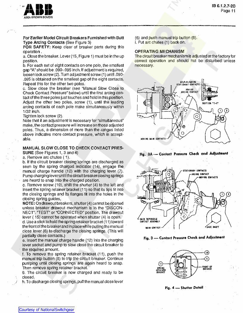
For Earlier Model Circuit Breakers Furnished with Butt Type Arcing Contacts (See Figure 3) FOR SAFETY: Keep clear of breaker parts during this operation. a. Close the breaker. Lever(15, Figure 1) must be in the up position. b. For each set of eight contacts on one pole, the smallest gap "A" should be .090-.095 inch. If adjustment is required, loosen lock screw (2). Turn adjustment screw (1) until .090-.095 is obtained on the smallest gap of the eight contacts. Repeat this for the other two poles. c. Slow close the breaker (see "Manual Slow Close to Check Contact Pressure" below) until the first arcing contact of the three poles just touches and hold in this position. Adjust the other two poles, screw (1 ), until the leading arcing contacts of each pole make simultaneously within 1/32 Inch. Tighten lock screw (2). Note that if an adjustment·is necessary for "simultaneous" make, the contact pressure will increase on those adjusted poles. Thus, a dimension of more than the ranges listed above indicates more contact pressure, which is acceptable.
MANUAL SLOW CLOSE TO CHECK CONTACT PRES· SURE (See Figures 1, 3 and 4) a. Remove arc chutes ( 1 ). b. If the circuit breaker closing"springs are discharged as seen by the spring charged indicator (14), engage the manual charge handle (12) with the charging lever (7). Pump charging lever until the circuit breaker closing springs are heard to snap Into the charged position. c. Remove screw (19), shift the shutter (4) to the left and Insert the spring retainer bracket ( 11) so that its tips fit into the closing springs and its flanges fit into the holes in the closing spring guides, NOTE: On drawout breakers, shutter (4) cannot be opened unless breaker drawout mechanism is in the "DISCONNECT'', "TEST" or "CONNECTED" position. The drawout lever ( 15) cannot be operated when shutter (4) is open. d. Use a stick to hold the spring retainer bracl<et (11) toward the front of the breakerand in place while pulling the manual close lever (6) to discharge the closing springs. (This will partially close contacts.) e. Insert the manual charge handle (12) Into the cl1arging lever socket and pump to slow close Hie circuit breaker to the required amount. f. To remove the spring retainer bracket (11 ), push the manual trip button (8) to trip the circuit breaker. Continue pumping until closing springs are again heard to snap. Then remove spring retainer bracket. 9. The circuit breaker is now charged and ready to be closed. h. To discharge closing springs, pull the manual close lever
(6) and push manual trip button (8). · i. Put arc chutes (1) back on.
OPERATING MECHANISM
IB 6.1.2.7·20 Page 11
The circuit breaker mechanism is adjusted at the factory for correct operation and should not be disturbed unless necessary.
N0\1100 MAIM COHTACTS-
Fig. 3A - Contact Pressur• Check and Adlustmont
AAllt SErOADLl COOTi\CT ASSU41LV
MAlll COOT ACT m
STATIQMARY COllTM:TS ARClllG COOTM:T
M(IVIN$ CMTACTS
Fig. 3 - Contact Pre .. ure Check and Adfustmenl
® !""~ ~ TAIM II '""" Of 3RlAKUI
GRACK T
Fig. 4 - Shutter Detail
Courtesy of NationalSwitchgear.com
ID O. l,t:,f 0 .GLJ
Page 12 ,, ••• , ASEA BROWN BOVERI
SECONDARY LATCH ROLLER
~PRIMARY TRIP LATCH
TR I PPER BAR PRIMA~Y LATCH ROLLER
SECOHOARY TRIP LATCH --
Fig. 5 - Primary Trip Latch Adjustment Fig. 6 - Tripper llar Tripper Adjustment
,,. ... CLOS I MQ CO ll
3
SHUNT TRIP OF.VICE
SECONDARY CLOSE LATCH
fig. 7 - Primary Close Latch Adjuslment fig. 8 -- Shunt Trip Device Adjustment
\ ) •,,_,..,
Courtesy of NationalSwitchgear.com

·~,~1111 ASEA BROWN BOVF.RI
FOR SAFETY: Keep hands clear of all moving parts. Serious Injuries can result if a person comes in contact with breaker parts when the breaker Is being opened or closed, or closing springs are being charged or discharged. Use extension tools for manipulating breaker parts . If field testing indicates breaker malfunction, the following items may be checked.
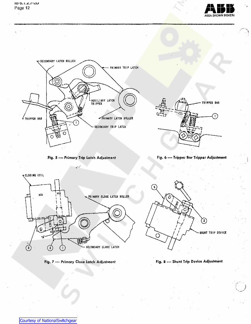
Primary Trip Latch Figure 5 shows the arrangement necessary for the breaker t~ be In the closed P.osition. The spring holds the secondary trip latch down against screw (1 ). The secondary trip latch holds the secondary latch roller up, which In turn holds the opposite end of the primary trip latch down. This prevents the primary latch roller from moving to the left and opening the breaker. If none of the various trip devices are acting on the tripper bar or the auxiliary latch tripper to open the breaker or to prevent the breal<er from closing and the breaker still will not close', then the following adjustment should be made. a. Turn strew (1) down to insure that secondary trip latch will hold the secondary ·latch roller up. b. With the breaker closed, turn up on screw (1) until the breaker trips. c. Turn screw (1) down two turns.
z
1'ft!PPLP f>o!>lilOf\)
'
Fig. 9 - Magnetic Latch Trip Adiu•tment Type K-30005 and K-40005 Circuit Breakens
Tripper Bar Adjustment (Figure 6)
IB 6.1.2.7·20 Page 13
To Insure that tripper bar and tripper is in the correct position with the secondary trip latch, check and adjust as follows: a. Turn screw (1) down to make certain the tripper will not trip out the breaker. b. With breaker closed, turn screw (1) up until the breaker trips, c. Turn screw (1) down 2 3/4 turns.
Primary Close Latch (See Figure 7) a. With the circuit breaker closing springs charged and
breaker contacts opened, the closing plunger (3) Jn deenergized position, there should be a 1/16" air gap between the rod (1) and the secondary latch (2) at point "A". Turn rod ('I) for 1/16" dimension.
Shunt Trip Device (See Figure 8) a. Turn trip rod (2) down until Gircuit breaker does not trip with plunger (3) held down. b. Close circuit breaker. c. Push plunger (3) down as far as possible and hold In this position while turning up trip rod ( 2) until circuit breaker just trips. d. Turn rod (2) up 2 1/2 to 3 turns.
Magnetic Latch Device (Type K·3000S, K·4000S) Trip Adjustment (Refer to Figure 9) 1. Turn adjusting screw (1) out as far as possible so thatthe circuit breaker will not trip when the magnetic latch trips. 2. Remove the terminal block cover on the solid state assembly by removing two lower screws (Fig. 12). Disconnect two wires at terminals 15 and 16. 3. Close the circuit breaker. 4. While lightly pushing at point "A" so that the lever(2) does not move t.hrough Its full strol<e and trip the circuit breaker, momentarily apply the voltage (3 V) from two dry cell batteries, size "D", to the two wires(+ to wire 16, --to wire 15) that were disconnected In operation 2. Tho magnetic latch should trip. 5. Gradually release the hold on lever (2). · 6. While holding the lever (2) in the tripped position, turn in on screw (1) until the circuit breaker just trips, then turn In one additional turn. 7. Replace wires 15 and 16 and the terminal block cover.
Courtesy of NationalSwitchgear.com

IB 6.1.2.7-2D Page 14
ELECTRO-MECHANICAL OVERCURRENT TRIP DEVICE ADJUSTMENTS Short Time Delay Adjustment (See Figure 11) (OD Types 400, 500, 900, 1000). Push the short time lever to rear of breaker and slide the lever to the desired band. Make sure the lever pin drops into the pin hole.
Long Time Delay Band Adjustment (Figure 10) (OD Types 400, 500, 600). To reset Jong time delay to a different band, first loosen the
, locking screw for long-time delay adjustment approxi· mately one turn. Turn the adjusting knob until the pointer lines up with the desired line marked "Minimum Time" "Instantaneous Time" or "Maximum Time". Retighten the locking screw. NOTE: OD·300 has only one long-time delay setting: therefore resetting is not required.
" Plck·Up Setting Adjustments (Figure 1 O) Pick·up settings may be changed by turning the appropri· ate adjusting screw until the moving indicator lines up with the desired pick-up point line. NOTE: The top line corresponds to the top pick-up point, the second line from the top corresponds to the second pick-up point from the top, etc.
JH$1ANTANtOU$ PICK•UP POllHS fOlt Q0•300, 600 & JOO
SHOlll•fllU "CR•UP ,GINU ,0. 00•4M, 500, 900 l 1000
lllS1AliH14[0US 'ICK·UP 901NTS fOll OO·~OQ, 000 & 900
AOJUUll(HI S:Cftf\'l ,OR: INSTANl.lH£0US Plc- .. u,
06·300, GOO & 100 l!IORT-llM( 'JC•·~·
00· 400, ~00, 900 I 1000
. ,..
''llll' ASEA BROWN BOVERI
Armature Trip Travel Adjustment.
'.''.· ~·eh:~lll®N •ElPlli!JWl@lN ©~WWIQN 01.\Ufl©N:. '"~I> L ·~ ,._,,r - > , ~', " ' ' Z ) ~ ; ' c "'
l<EEF' HANDS CLEAR OF ALL MOVING PARTS. THE CIFlCUIT BREAKEFl WILi_ TlllP TO THE "OPEN" POSI· TION WHILE CHECKING OR ADJUSTING THE.ARMATIJl'IE TfilP TRAVEL The overload device trip travel is set at the factory; how· ever, if trip travel readjustment is required due to replace· ment of overloads or other parts, then readjust as follows: a. (See Figure 10.) Bacl<out on the two trip adjusting screws until the screws are engaging the nut by approximately two turns. b. Charge springs and close circuit breaker. c. Using a one foot long (approximate) stick, push up on long time armature (thick armature) at point "A", and,hold It tight against the magnet. Turn in screw marked "Right" until the breaker just trips, Continue to turn the screw in an additional 1 1/2 turns, d. Charge springs and close circuit breaker. Push upon the thin armature and adjust the screw marked "Left" using the same procedure as "c" above. e. Readjust the trip travel at the other two poles using the same procedure (steps a through d) . Field Testing of Electro-Mechanical Overcurrent Trip Devices Refer to IB·9. 1. 7-5 for complete testing of devices .
Fig. l 0 - Ovorload Device Adlustmenl•
MAX!llUll illOH·TllU OlLU ~Ill llOl(
SHOU· IHI( &CLAY UHD LIVU I ,oA oo.•oo, ~oo. no g 1000 ~~.~~~~-( $HO•tt SU ,&R
INIOM[OIAH GANO
IN!UU(OIAll SHOR1•1111f OHU K PIN 1101.E: I~
WUll~U!t SMOH•Tlhl DELAY L PIN·H0l£ r .. ~--
! ... -. --·· -
- - - -.-Q. I ··+·--·~·
W:lo 11 - Shnrt .. Thna Oelav Band Adlu1tments
Courtesy of NationalSwitchgear.com

.,,1111 ASEA BROWN BOVERI
SOLID STATE OVERCURRENT TRIP DEVICE SET .. TINGS (See Figure 12) No adjustments are necessary in selecting trip settings on this trip device. The selector plugs (solid circle) allow flexibility In settings and may be moved from one plug tap to another, consistent, however, with the pickup and time band settings necessary for proper circuit protection. Make certain that the selector plugs are pushed In completely for proper operation. If a plug is left out or not secure, the affected element will trip at the minimum setting shown, for safety, but coordination will be affected.
Field Testing of Solid State Overcurrent Trip Devices For complete testing of these devices, refer to the following Instruction Bulletins: IB-9.1.7-21 (Device In RED CASE) IB-9.1.7-22 (Device in GRAY CASE)
LUBRICATION
Only two lubricants are approved for use on the K-Line circuit breaker. Lubricated during final assembly, the Kline circuit breaker should not require additional lubrication during its service life when applied in accordance with ANSI C37.'13. If, however, the breaker is applied in unusual situations defined by ANSI C37.13, has lubrication contaminated with dirt and d~.tiris, or has parts replaced, relubrlcation should be performed as follows:
When mechanism cleaning and relubrlcation is required, do not spray solvents down through the mechanism to remove old lubricants, dust, and debris.
~- -- -<ID [ d19~'1!., &Jt:b PICKUP &"':L 102. 6 01
SHORT-TIME GROUND
tml @"0600] [9 ·~ @o 6 6 oJ AMPERE LONG· TIME INST. TAP --·---
I I SOLID STATE TRIP I .@__ ([j)
- ~-
Page 15
Do not use dichlorodifluoromethane on any part of the circuit breaker. These solvent tend to wash debris into the bearing areas of the breaker, while at the same time removing any existing lubricant. Breaker performance will be compromised when these cleaning techniques are employed.
Proper relubrication requires disassembly, thorough cleaning by wiping, then reassembly using a brush or other means for reapplying the lubricants listed.
1. Apply NO-OX-ID special grade A" grease from Dearborn Chemical Company to all mating surfaces of moving current carrying joints. Do not apply NO-OX,ID grease on any main or arcing contact surfaces. Primary disconnects should be maintained by reapplying NO-OX-1 D during maintenance periods. NO-OX-ID is available from Asea Brown Boveri in one pint cans, Number 713222-AOO.
2. Apply Anderol 757 synthetic grease manufactured by HULS AMERICA, INC. to mechanism parts, bearings and pins. DO NOT APPLY GREASE TO LATCH OR ROLLER SURFACES. Anderol 757 is available from Asea Brown Boveri in four ounce tubes, part Number 712994-AOO.
3. Anderol synthetic lubricant Is also available as a spray, Anderol 732. Anderol 732 is useful as a solvent for removing old lubricant, dirt, and debris In the mechanism. It can NOT be used as a substitute for Anderol 757, Please observe the following warnings:
a. DO NOT apply light machine oil, or thin spray lubricants to lubricate any mechanism part.
b. DO NOT attempt to relubricate the spring charg-ing motor gearbox. It is sealed and should not require repacking.
c. DO NOT lubricate magnetic latch device or other-wise clean or spray with any substance.
4. Use only the recommended lubricants. Use of other than approved lubricants can cause breaker misoperation at temperature extremes.
Courtesy of NationalSwitchgear.com

IB 6.1.2.7·20 Page 16
DIELECTRIC WITHSTAND TESTS ON POWER AND CONTROL CIRCUITS
1. Dielectric withstand tests on circuit breakers shall be made to determine the ability of the insulation to withstand overvoltages.
2. A 60-cps alternating sinusoidal voltage (rms) value equal to the specific voltage shall be used. All voltages used in the dielectric withstand test shall be measured in accordance with ANSI Measurement of Voltage in Dielectric Tests, C68.1.
3. Duration Of Test - The dielectric test voltage shall be applied for a period of 60 seconds. The duration of the test may be one second if a voltage 30% greater than that specified is applied.
4. Condition 01 Circuit Breaker'To Be Tested - Dielectric tests shall be made on a new, completely assembled circuit breaker and not on individual parts. When a circuit breaker is tested in the field or after storage, the test voltage shall be 75% of the value listed in C37.50-3.5.2. (Value shown below.)
5. Temperature At Which Tests Are To Be Made -Dielectric tests shall be made at any temperature between 1 o and 55 C '' •
6. Magnitudes And Point Of Application Of Test Voltage -The dielectric test shall be applied as follows:
,,1111· ASEA BROWN BOVERI
a. With circuit breaker in open position, apply 2200 volts ( 1 000 volts plus twice 600 volts on new breakers; 0.75 x 2200 = 1650V on breakers that have been in service):
i. Between live parts, including both line and lo ad terminals, and metal parts that are normally grounded.
ii. Between live terminals and load terminals.
b. With circuit breaker in closed position, apply 2200 volts on new breaker and 1650 volts on breakers that have been in service.
I. Between live parts and metal parts that are normally grounded.
ii. Between terminals of different phases.
c. With circuit breaker In either open or closed positions, apply 1500 volts (1125 volt on breakers taken out of service):
Note: Disconnect solid state trip unit, as a precaution.
i. Between control circuit and metal parts that are normally grounded. If the circuit breaker control circuit includes a motor, the motor MUST be disconnected during the dielectric test on the control circuit.
TABLE 2
TEST VOLTAGE TO BE APPl.IED FOFI ONE MINUTE TO TEST THE ABILITY 01' THE INSULATION TO WITHSTAND OVERVOLTAGES
-Breaker Open Breaker Clos11d Breaker Open or Closed
- - -1650 V ac - - 2300 V de 1650 V ac - • 2300 V do 1125 Vac- -1600 Vdo
Breaker In Service a. Between terminals a. Between terminals a. Between control circuit or and metal parts and metal parts · and metal parts normally
After Storage normally grounded. normally grounded. grounded. NOTE: Motor must be dis·
b. Between line and b. Between phases. conne~1ed from control load terminals. circuit for this lest.
After 1320 V ao - - 1860 V do t320 V ao - - 1860 V de 900 V ac - - 1260 V do
Short Circuit a and b as above a and b as above a as above
Courtesy of NationalSwitchgear.com
.. ",,1111 ASEA BROWN BOVeRI
d. Apply 1000 volts:
i. Between leads of new motors.
e. SPECIAL NOTES:
i. Apply 60% of the values given in (a) through (d) above on breakers that interrupted a short circuit.
ii. Motors that have been in service may fail dielectric due to a normal accumulation of debris from the commutator. Cleaning the motor will restore dielectric integrity.
iii. Do not perform dielectric testing on the solid state trip system.
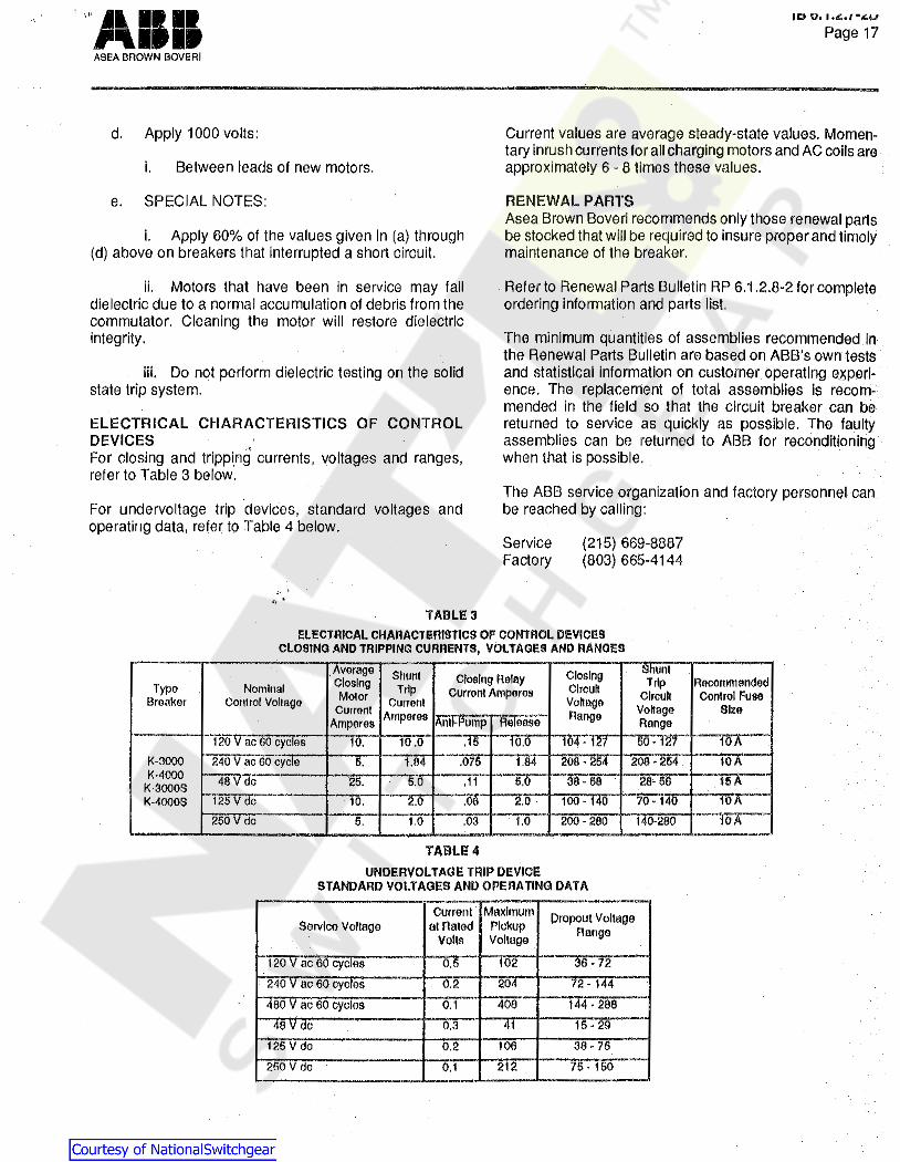
ELECTRICAL CHARACTERISTICS OF CONTROL DEVICES For closing and tripping' currents, voltages and ranges, refer to Table 3 below.
For undervoltage trip devices, standard voltages and operating data, referto Table 4 below.
' ' ,, . TABLE 3
ID u.1.L..f"IC.U
Page 17
Current values are average steady-state values. Momentary inrush currents for all charging motors and AC coils are approximately 6 - 8 times these values.
RENEWAL PARTS Asea Brown Boverl recommends only those renewal parts be stocked that will be required to insure proper and timely maintenance of the breakHr.
Refer to Renewal Parts Bulletin RP 6.1.2.8·2 for complete ordering information and parts list.
The minimum quantities of assemblies re<:orrnnended In the Renewal Parts Bulletin are based on ABB's own tests and statistical information on customer operating experience. The replacement of total assemblies Is recommended in the field so that the circuit breaker can be returned to service as quicl<ly as possible. The faulty assemblies can be returned to ABB for reconditioning when that is possible.
The ABB service organization and factory personnel can be reached by calling:
Service Factory
(215) 669-8887 (803) 665-4144
ELECTRICAL CHARACTERISTICS or CONTROL DEVICES CLOSING AND TRIPPINQ CURRENTS, VOLTAGES AND RANGES
Type Breaker
K-3000 K·4000
K-30006 K-4000S
-'Avorago Shunt Shunt Closing Relay Closing No1nl11al Closing Trip Circuit Trlp Recommended
Control Voltage Mo1or Curren! Curront Arnporos
Vohago Circuit Control Fuse Curren! Amp ores AntH'ump"~i'ioTeOOe Range Vohago Silo
Amperes Rongo -1201/ac 60 cycles 1u, 10.0 ,10 1u.O 1v• • 127 OU· 121 1011
240 V ac 60 cyc10 5. 1.84 .075 - 1.84 208. 264 200 ·• 264 ToA-· '"48Vcic 25. 5,0 '11 6.0 38. 60 28· 56 16 A -125Vdc - 10. 2.0 .Ou 2.0 100·1•0 70-140 """"""1i)i\-
250 V de . - 1.0 .03 t .0 200. 200 -·140·280 10 II 6.
-- ---TABLE 4
UNDERVOl.TAOE TRIP DEVICE STANDARD VOl.TAOES AND OPERA TINO DATA
--·. Current Maximum Dropout Voltage
Service Voltage at Rated Pickup Range Volts Voltage
t 20 v ac 60 cycles 0.5 j(), 36. 72
-· 240 v ac 60 cyc1os 0.2 204 r2 • 1•4
480 V ac 60 cycles 0.1 408 144. 200
48 V de - 0.3 41 15-~-
125 V do 0.2 106 38. 75
250 V do 0.1 212 75. 150 -
Courtesy of NationalSwitchgear.com

IB 6.1.2.7·2D Page 18
INTRODUCTION The standard solid state trip device on K-3000 and K-4000 is now the MICRO Power-Shield (MPS) microprocessor based trip device. Similar to MPS trip devices available on other low voltage ABB circuit breakers, the MPS trip device uses a single current sensor per pole and a magnetic latch to trip the circuit breaker. This trip device is equipped with long time and various combinations of short lime, instantaneous and ground. The MICRO Power .. Shield trip system has a tolerance band on long time of minus zero, plus ten percent (-0, +10%) which will allow the circuit breaker to carry its continuous current rating, but provide tripping above that value. Additionally, root mean square (RMS) current calculation on the long time trip element provides tripping based on the true heating value of the current passing through the circuit breaker. Below, the MPS trip device is described more fully. Following That field testing procedures, adjustments and field repair Instructions are prov'ided.
SOLID STATE TRIP SYSTEM The solid state trip system includes the sensors, the MICRO Power Shield solid state trip deviGe, the magnetic latch and the Interconnecting wiring. A current sensor is integrally mounted on each phase of the circuit breaker to supply a value of current flowing in the trip unit that is directly proportional to the current flqwing in the primary. When the value of the current flowing in the primary. exceeds the trip unit settings for a given time, a signal is sent to the magnetic latch causing the circuit breaker to trip. On a three phase, four wire, wye systems, provisions are made for input from a separately mounted sensor to obtain a residual connection of all four (4) sensors for sensitivity to ground currents.
MICRO Power Shield (MPS) Trip Unit (Figure 13) The MPS trip unit is visible on the front of the circuit breaker on the right hand side. It Is completely self powered, taking the tripping energy from the primary current flowing through the circuit breaker without the need for any addition I power supply. To cope with modern power systems where harmonics In the system can cause cable and bu sway overheating, the MPS unit calculates the root mean square value of the system current and provides tripping accordingly. Because the true heating value of the current is calculated, cable and busway overheating is avoided with the MPS trip system. This feature is standard on the long time element of all Model V6C and higher MPS trip units.
Protective Elements (Figure 14)
Ml 1111'. ,.,,,., ASEA BROWN BOVERI
Four basic trip elements within the MPS trip unit perform the protective functions: (1) long-time, (2) short-time, (3) instantaneous, and (4) ground. MPS types with various combinations of these protective elements are shown. Selection of type is dependent upon the protection and coordination requirements for the specific power circuit. The MPS trip unit is completely tested prior to shipment. Since there are no mechanical devices which may have lost adjustment during shipment, no readjustments, other than making required settings, need be made prior to placement in service. The following trip characteristics are available: long .. time setting and delay bands; shorttime settings and delay bands, with and without an 12 t characteristic; instantaneous setting; and ground setting and delay bands.
The MPS trip unit must be properly set, as required by the individual circuit, in order to provide the necessary protection. With the transparent cover removed, the rotary switches on the unit faceplate enable independent selection of the long-time, shorHlme, instantaneous, and ground characteristics as applicable. In addition, as part of the short-time, an ·12 t characteristics response has been Included. A two-position switch gives the user the choice of selecting this option.
The MPS trip unit protective elements, with the exception of ground, will cause the circuit breaker to trip at a value equallo the ampere range selector position times the pickup (threshold) setting of the various protective elements. The ground trip settings are marked on the faceplate in primary amperes.
Ampere Range Selector The ampere range selector switch provides two settings: fifty percent and one hundred percent of phase sensor rating. This exclusive feature effectively expands all trip element settings, except ground, by a factor of two.
)
Courtesy of NationalSwitchgear.com

.. ,lllll ASEA BROWN BOVERI
FlgurB 14 ·Aval/able MICRO Power-S/1le/d TRIP UNIT
MPS·3
MPS-30
Ml'S·4
Ml'S·40
MPS·5
MPS-50
Targets
x
x )(
x x x
x x x x x x x x x x x J( x x
Operation indicators (targets) are provided as standard on all types of MPS trip units. One indicator is provided for each of the protective trip elements included (long-time, short-time, instantaneous, and ground). Therefore, a maximum of four targets will be supplied based on the total number of trip elements in the particular trip unit. When a trip occurs, the target for the trip element which was responsible for tripping the o.rrcuit breaker will display the color orange. The target will retain Its position despite shock or vibration as long as the breaker remains open. The target will reset automatically within two seconds after the circuit breaker is closed and the sensors detect current flow through the circuit breaker. Upon closing, if there is a trip condition, the target will reset instantly and a new target will display corresponding to the trip element which caused the trip condition.
Figure 16 - Ct11ro11t Sensors and Circuit Breakor Set1111gs
3000 1500, 3000 500, 600, 800, K·3000M,
900, 1000, 1200 K·4000M
3200 1600, 3200 500, 600, 900, K·3200M, 900,1000,1200 K·4000M
4000 2000,4000 500, 600, 800,
K-4000M 900, 1000, 1200
x x
x
x
IL" u, 1,.c;,1•,LJ
Page 19
TD9601
x x TD9601 TD9603
TD9602 TD9604
x )( TD9602 TD9604 TD9603
TD9602 TD9604
x )( TD9602 TD9604 "rD9603
AVAILABLE SETTINGS
Ampere Range Selector Switch (Figure 15) The ampere range selector switch has two positions. The maximum setting corresponds to the rating of the phase sensor. The minimum setting corresponds to fifty percent of the phase sensor rating.
WHlcN MAKING LONG·TIME, SHOFH-TIME, INSTANTANEOUS, AND/Ofl GflOUND SEoTTINGS, THE FlO·· TARY SWITCH MUST f3E IN THE DETENT ADJACENT TO THE: SETTING ON THE TfllP SYSTEM FACEPLATE. IF THE: FlOTAl~Y SWITCH IS NOT IN THt:. DETENT, THE MISDEcTENTED THIF' ELEMf:NT IS AUTOMATICALLY SET AT ITS LOWEST SET POINT. THIS APPLIES TO THflESHOl.D SETTINGS AND TIME DELAY SETTINGS.
Long-Time The long-time setting may be 0.5, 0.6, 0.7, 0.8, 0.9, or 1.0 times the ampere range selector setting. Three long-time delay bands are provided. The three bands are labeled MAX (maximum), INT (intermediate), and MIN (minimum).
Short-Time The short-time setting may be 2, 3, 4, 6, 8, or 10 times the ampere range selector setting. Three short-time delay bands are provided: MAX (maximum), INT (intermediate), and MIN (minimum). A two-position switch is provided to select an 1 't type response. The switch when placed In the OUT position selects the normal current characteristic curve. By placing the ·1 2t switch in the IN position, the 1~t current characteristic curve is selected.
Courtesy of NationalSwitchgear.com
IB 6:1.2.7"20 Page 20
Instantaneous The instantaneous setting may be 3, 4, 5, 7, 1 o, or 12 times the ampere range selector setting.
Ground (Figure 15) The available ground settings vary with the phase sensor rating. These settings are marked on the faceplate in primary amperes. Three ground fault display bands are provided: MAX (maximum), INT (intermediate), and MIN (minimum). The time current delay bands of the ground elements include an i't characteristic that is a permanently programmed feature. Unique circuitry of the MPS trip unit responds to low level arcing faults by summing the erratic currents associated with arcing, then providing a trip when that sum is above the trip threshold for a preprogrammed period of time.
Self Monitoring A continuous monitoring of the microprocessor function is provided consisting of a red Light Emitting Diode (LED) mounted in the faceplate. When primary current is approximately six percent of the sensor rating, the LED will blink approximately one time per second. The LED does not blink at current level below 6%. Servicing is required if the LED remains lit, but does not blink, or does not illuminate at all current levels above 6%.
Making Settings The settings of current threshold and delay bands must be determined by an analysis of the protection and coordination requirements of the power system. The ampere range selector and the short-time 12t switch are two-position switches on the MPS trip unit. All other settings are rnade by means of six position rotary switches. The longtime, short-time, and instantaneous trip element thresholds are multiple of the ampere range selector setting. The ground trip value in primary amperes is selected directly by its rotary switch setting. An example of settings:
4000 Amp circuit breaker with 4000 Amp sensor
Long-tirne setting required: 3200 amperes.
Instantaneous setting required: 20,000 amperes.
Ground setting required: 'IOOO amperes.
'~1111· ASEA BROWN BOVERI
·1. Set AMPERE RANGE SELECTOR at 4000 amperes.
2. Set LONG-TIME SWITCH at 0.8 setting· (0.8 x 4000 = 3200).
3. Set INSTANTANEOUS SWITCH at 5 setting -(5 x 4000 = 20,000).
4. Set GROUND SWITCH at 1000 setting.
5. Set DELAY BANDS required for coordination.
Rotary switches must be positioned in the detent when making pickup and time delay settings. There are NO intermediate settings bfltween detents. Failure to position the rotary switch in the detent will automatically reset the misdetented trip element to its lowest pickup value or time delay for the misdetented relay rotary switches.
Testing
A test set designated type 606 and designed specifically for use with the MPS trip system Is available. Refer to IB 6.1.1.7·4. Primary current injection Is covered below.
A test function switch In the faceplate is provided for testing only with the type 606 test set.
WHEN USING PRIMARY CURRENT TO TEST THE MICFlO POWfH·Shioid TFllP SYSTEMS EQUIPPED WITH THE GFlOUNDTRIF' FUNCTION, THIS FUNCTION MUST BE DEFEATED IN OF1DEf1 TO TEST THE OTHER TRIP ELEMENTS. A SPECIAL GFlOUND DEFEAT TEST CAl3LE (PAFn 7·12918· T09) MUST BE USED. THE CABLE IS INSEFlTED TEMPORARILY IN THE CIRCUIT CONNECTING THE TRIP UNIT AND THE CIRCUIT 13REAKEFl. FAILUllE TO USE THE GROUND DEFEAT TEST CABl_E CAN RESULT IN DAMAGE TO THE Ml· C RO Power-Shield TRIPPI NG SYSTEM. CALL THE NEAR .. EST ASEA BflOWN BOVERI DISTRICT OFFICE TO or·1DEFl EITHER THE GROUND DEFEAT TEST CABLE (PART 71~l918-T09) OR THE D.E.S.P. TEST CABLE (PARI 71391.8-T10).
\ . ' ./
)
Courtesy of NationalSwitchgear.com

···Jl 1111 ,., ., .• ASEA BROWN BOVERI
PROCEDURE FOR FIELD TESTS ON K·LINE CIRCUIT BREAKERS
MPS Solid State Trip System testing
There are two ways to evaluate the MICRO Power-Shield solid state trip system. A secondary current injection test set, the type 606 MPS tester, has been designated specifically for use with the MPS box. This tester simulates the current from the current sensor and allows evaluation of the MPS solid state box and magnetic latch. Used in conjunction with the TEST FUNCTION selector switch on the MPS box, the type 606 tester can be used to evaluate long-time, short-time, instantaneous, and ground with or without maglatch. The full range of the circuit breal(er frame sizes can be evaluated with the 606 tester. To obtain a tester, call the nearest Asea Brown Boveri sales office and ask for part 714516-T01. Refer to Bulletin 6. 1. 1. 7-4, which was written for the 606 test set.
The other method of evaluating the MPS solid state trip system is by primary current injection using the primary current injection test set. This method allows evaluation of the sensors, MPS solid state box, magnetic latch and interconnecting harnesses. Below is a procedure for performing this field test.
Primary Current Testing • MfCRO Power-Shield Type MPS
Notes:
1. Refer to time current curves TD-9601, TD-9602, TD-9603, TD-9604.
2. When checi<ing calibration, set functions not being tested at their highest threshold value.
3. On MPS trip units equipped with ground, the ground trip must be defeated by using a special cable assembly, part number 713918-T09. This assembly is installed between the solid state box and the breaker wiring harness. Failure to use this harness will prevent primary current testing of the long-time delay function.
4. The TESTING FU NC Tl ON selector switch on front of the MPS solid state box operates only with the optional Type 606 secondary current injection test set. The position of this switch has no influence during primary current injection tests.
5. The closing springs must be charged and the circuit breaker closed before each test below.
Instantaneous Threshold Test
IB 6.1.2.7·20 Page 21
1. Position the other trip elements selectors at their highest threshold value.
2. Position trip system ~lange Selector In the desired position, either full or one-half breaker sensor rating.
3. Put instantaneous selector switch in the four times (4X) setting.
4. Test for the actual threshold by Increasing test se.t current until the breaker trips.
5. The threshold tolerance is +/-10% on all selector switch settings.
6. Instantaneous times cannot be accurately measured with primary current test sets. Such times can only be measured with oscillographic equipment. Percent error in the timer and meter of primary current test sets can make It appear that the Instantaneous does not fall Inside Its band.
Long-Time Delay Test
1. Position the other trip element selectors at their highest threshold value.
2. Position Range Selector In desired position.
3. Put long-time selector in the one limes (1 X) setting.
4. Set test set current so that current through the breaker.is three times (3X) trip system Range Selector setting. Times should be as follows:
Courtesy of NationalSwitchgear.com

10 6.1.2.1-:m Page 22
Shott· Time Delay Test
1. Position the other trip element selectors at their highest threshold value.
2. Position Range Selector in desired position. To prevent stress on the solid state components, however, the lower position Is recommended.
3. Put 121 switch in the OUT position.
4. Put short-time selector in the two times (2X) setting.
5. Set test set current so that current through the breaker is four times (4X) trip system Range Selector Setting. Times should be as follows:
6. Put Ft switch in the IN position: "
7. Set test set current so that current through the breaker is 1.5 times the two times (2X) trip system Range Selector setting. Times should be as follows:
Ground Trip Delay Test
1. Position the other trip element selectors at their highest threshold value.
2. Remove the ground defeat cable assembly. Connect the breaker harness directly to the MPS box.
3. The Range Selector has no influence on the ground settings.
Jlll 11,; ,., •. , ASEA BROW~ BOVERI
4. Put the ground trip selector In the minimum available ground setting (100A on 200A and BOOA sensors, 300Aon 1600A through 2500A sensors, and 500A on 3000A through 4200A sensors). Device nameplate has actual current values on ground trip available.
5. Set test set current so that current through breaker Is three times (3X) the minimum setting selected in (4) above. Time should be as follows:
6. On breakers with 4-wire ground and 4-wlre ground on double-ended substations, the remove neutral sensor can be simulated with the breaker -mounted left pole sensor. On the back of the breal\er temporarily reverse wires marked W and N. These wires appear on secondary disconnect points 17 and 18. Connect the circuit breaker so that current flows through the left pole only, and check the ground system as in (5) above. Following the test, return wire W and N to their proper locations.
Note that wire N is on terminal 18 of the secondary disconnect and W Is on terminal 17 for 4W ground boxes. On double-ended sub, 4W ground boxes W is on 18 and N Is on 1 7.
7. As an alternative to (6) above, a separate neutral sensor can be used to operate the MPS trip system. Optional test cable assembly 71391 8-T1 O provides leadsout which may be connected to a neutral sensor. The type used is at the discretion of the tester. It is recommended tt1at it be of the type planned for final installation. Connect the primary current Injection machine to pass current through the neutral sensor.
Courtesy of NationalSwitchgear.com

,',,1111 ASEA BROWN BOVERI
ltl 1).1.Z.f•<(U
Page 23
NOTE THAT 12 t FUNCTION IS A PERMANENT FEATURE OF MPS GROUND TRIP CHARACTERISTIC CURVES.
FIELD REPAIR INSTRUCTIONS
MICRO Power·Shleld Trip Device Removal and Installation
". NEVEi~ RE:MOVE AN MPS BOX HARNESS WHEN THE CIRCUIT BREAKER IS CLOSED AND CONDUCTING CURRENT. THE MPS BOX PLUG AND HARNESS PLUG WILL BE DAMAGED BY A HIGH VOLTAGE FLASHOVER. PERSONAL INJllfW MAY ALSO RESULT
1. Flemove the two nylon screws which retain the trip system harness plug to the MPS device, Retain for re-use.
2 , Remove the fou r self-tapping screws holding the M PS device shield and remove tho shield.
3, Remove the three screws, lockwashers, and nuts that retain the MPS device, then remove the device from the breaker.
4, To reinstall, reverse the above procedure.
Metallic screws must not be used to retain the MPS trip system harness. Should a metallic screw fall into the trip system, serious damage can result. DO NOT or> ERA TE THE CIRCUIT BREAKER WITHOUT THE HAHNESS SCHEWS IN PLACE.
The MPS trip dHvice rod poly<Jster shield must be in place during breaker operation,
Magnetic Latch Removal
THE CIRCUIT 13REAKER MUST BE DE-ENERGIZED, liACKED OUT AND REMOVED FROM THE SWITCHGENl PRIOR TO PERFOl-lMING THIS PHO· CEDURE. (ON STATIONAHY BREAKERS IT IS NOT NECESSAHY TO HEMOVE THE BREAKER R; HOWf=VER, THE MAIN E3US AND CONH10L POWER MUST BE DE-ENERGIZED. THE CLOSING SPRING MUST BE DIS-CHAHGED WITH THE MAIN CONTACTS OPEN,
1. liernove the reset spring from its circuit breaker jackshaft mounting.
2, Disconnect the "B" and "F" leads from the breaker harness to the magnetic latch,
3. Remove the two large countersunk screws from the magnetic latch assembly mounting bracket and remove the magnetic latch assembly from the circuit breaker.
4. To reinstall, reverse the removal procedure.
Courtesy of NationalSwitchgear.com

11:.10.1.~.(";<U
Page 24
Maglatch Pretravel Adjustment
This adjustment must be performed with the circuit breal1er closed. Extreme care must be exercised in avoiding moving parts. Drawout circuit breakers must be racked to the disconnect position. It is mandatory on stationary breakers that the main bus be de-energized. Control voltage on stationary breaker must also be de-energized.
1. Perform this adjustment only after maglatch replacement or when automatic trip problems with the maglatch have been observed.
2. Ideal maglatch operation Is attained when maglatch armature pretravel of 0.062 to 0. 125 inches is achieved. Accepted breaker tripping is the guiding criteria.
" .
,,1111 ASEA BROWN BOVERI
3. Pretravel may be evaluated measuring the gap be· tween the magnetic latch plunger and the adjusting screw on the bracket attached to the trip bar of the closed circuit breaker. Care must be tal<en not to move this bracket as breaker tripping can result.
4. Loosen the t inch nut on the adjusting screw, then adjust the screw in the required direction to attain acceptable pretravel using an open-ended 51
16 inch wrench. It will be necessary to hold the tripper bar secure to keep it from rotating as the adjustment is made.
5. Retighten the t inch nut to lock down the adjusting screw.
Lubrication
ABB DOES NOT RECOMMEND LUBRICATION OF /\NY KIND ON ANY PAflT OF THE. MAGNETIC LATCH ASSEMl3LY.
Courtesy of NationalSwitchgear.com

,,1111 ASF.A BROWN BOVERI
" ..
IB 6.1.2.7·20 Page 25
Courtesy of NationalSwitchgear.com

''1111 ASEA BROWN BOVE RI
ASEA BROWN BOVERI, INC. ABB Power Distribution Inc. Circuit Breaker Division P.O. Box 100524 Florence, South Carolina 29501
Phone: (803) 665·4144 Telecopler: (803) 664·0520
)
Printed In U.S.A.1M 0392
Courtesy of NationalSwitchgear.com
Related Documents

![Rua%20da%20 constituição 1,11[1]](https://static.cupdf.com/doc/110x72/557ea32fd8b42ac5658b49af/rua20da20-constituicao-1111.jpg)