LECTURE (CU): DESIGN OF MEDICAL DEVICES CARRER: BIOMEDICAL ENGINEERING Paulo Piloto Departamento de Mecânica Aplicada UC: PROJECTO DE DISPOSITIVOS MÉDICOS CURSO: ENGENHARIA BIOMÉDICA

Welcome message from author
This document is posted to help you gain knowledge. Please leave a comment to let me know what you think about it! Share it to your friends and learn new things together.
Transcript

LECTURE (CU): DESIGN OF MEDICAL DEVICESCARRER: BIOMEDICAL ENGINEERING
Paulo PilotoDepartamento de Mecânica Aplicada
UC: PROJECTO DE DISPOSITIVOS MÉDICOSCURSO: ENGENHARIA BIOMÉDICA
CURRICULAR UNIT ‐ SYLLABUS
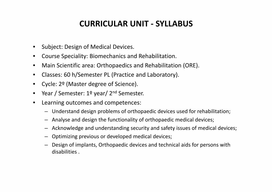
• Subject: Design of Medical Devices.• Course Speciality: Biomechanics and Rehabilitation.• Main Scientific area: Orthopaedics and Rehabilitation (ORE).• Classes: 60 h/Semester PL (Practice and Laboratory).• Cycle: 2º (Master degree of Science).• Year / Semester: 1º year/ 2nd Semester.• Learning outcomes and competences:
– Understand design problems of orthopaedic devices used for rehabilitation;– Analyse and design the functionality of orthopaedic medical devices;– Acknowledge and understanding security and safety issues of medical devices;– Optimizing previous or developed medical devices;– Design of implants, Orthopaedic devices and technical aids for persons with
disabilities .

CURRICULAR UNIT ‐ SYLLABUS
• Prerequisites:– Understand musculoskeletal functionality for orthopaedic and rehabilitation.– Understand static and dynamic behaviour of deformable and rigid bodies.– Apply solid stress and fluid flow analysis principles in simple systems.– Select biomaterials for biomedical applications.
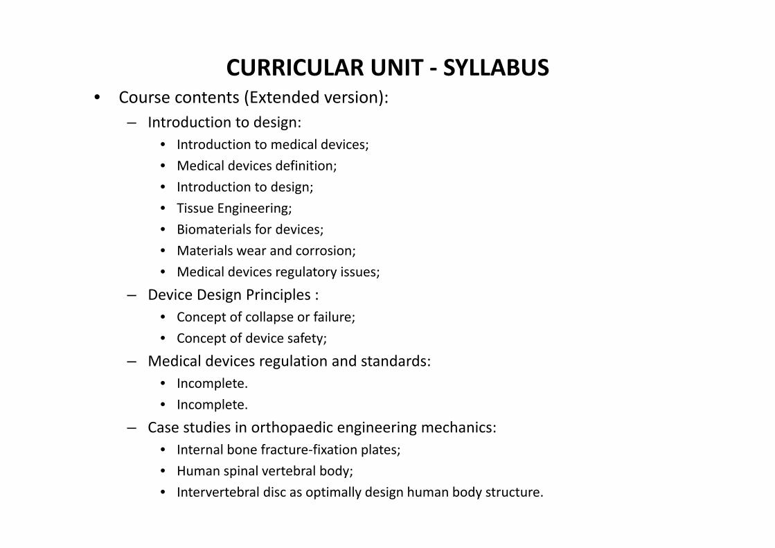
CURRICULAR UNIT ‐ SYLLABUS• Course contents (Extended version):
– Introduction to design:• Introduction to medical devices;• Medical devices definition;• Introduction to design;• Tissue Engineering;• Biomaterials for devices;• Materials wear and corrosion;• Medical devices regulatory issues;
– Device Design Principles :• Concept of collapse or failure;• Concept of device safety;
– Medical devices regulation and standards:• Incomplete.• Incomplete.
– Case studies in orthopaedic engineering mechanics:• Internal bone fracture‐fixation plates;• Human spinal vertebral body;• Intervertebral disc as optimally design human body structure.
CURRICULAR UNIT ‐ SYLLABUS• Teaching and learning methods:
– Theoretical and practical exposition of the fundamental concepts should be presented at classes, complemented with practical exercises. The remaining period should be used to solve working projects.
– Out of classes, students are invited to solve problems and prepare poster sessions.
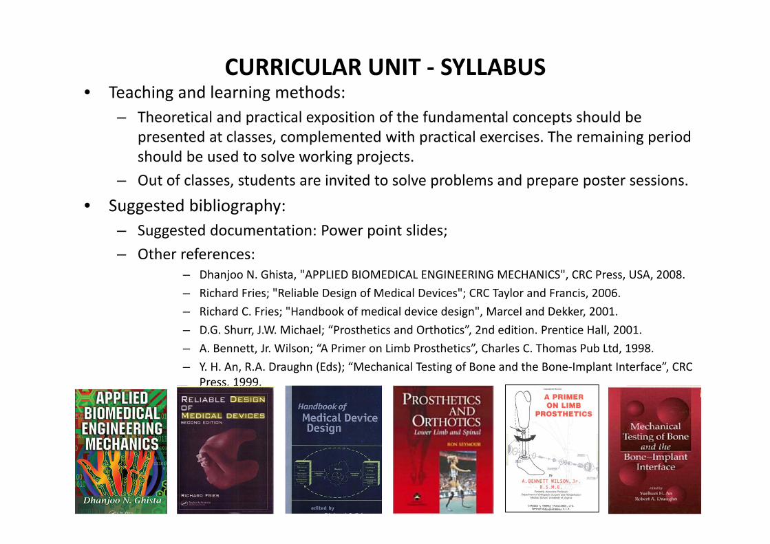
• Suggested bibliography:– Suggested documentation: Power point slides;– Other references:
– Dhanjoo N. Ghista, "APPLIED BIOMEDICAL ENGINEERING MECHANICS", CRC Press, USA, 2008.– Richard Fries; "Reliable Design of Medical Devices"; CRC Taylor and Francis, 2006.– Richard C. Fries; "Handbook of medical device design", Marcel and Dekker, 2001.– D.G. Shurr, J.W. Michael; “Prosthetics and Orthotics”, 2nd edition. Prentice Hall, 2001.– A. Bennett, Jr. Wilson; “A Primer on Limb Prosthetics”, Charles C. Thomas Pub Ltd, 1998.– Y. H. An, R.A. Draughn (Eds); “Mechanical Testing of Bone and the Bone‐Implant Interface”, CRC
Press, 1999.

CURRICULAR UNIT ‐ SYLLABUS
• Assessment:– Final season (EF):
• continuous assessment with working projects to be presented at classes (oral presentations with power point slides, with written reports in word format;
• Labor students with special statute may require Exam during final season.
– Appeal season (ER): Exam;– Special season (EE): Exam;
• Language of classes: Portuguese and English

INTRODUCTION TO MEDICAL DEVICES
• Medical Device [Decreto‐Lei n.º 78/97, de 7 de Abril] (In Portuguese):– “Qualquer instrumento, aparelho, equipamento, material ou outro artigo utilizado
isoladamente ou combinado, incluindo os acessórios e suportes lógicos necessários aoseu correcto funcionamento destinado pelo fabricante a ser utilizado em seres humanospara fins de diagnóstico, prevenção, controlo, tratamento ou atenuação de uma doença,lesão ou deficiência, para fins de estudo ou de substituição ou alteração da anatomia oude um processo fisiológico ou para fins de controlo da concepção, e cujo efeito principalpretendido no corpo humano não se alcança por meios farmacológicos, imunológicos oumetabólicos, mas cuja actuação possa ser apoiada por esses meios .”
• Medical Device [Directive 2007/47/ec of the European Parliament]– “instrument, apparatus, appliance, software, material or other article, whether used
alone or in combination, including the software intended by its manufacturer to be usedspecifically for diagnostic and/or therapeutic purposes and necessary for its properapplication, intended by the manufacturer to be used for human beings. Devices are tobe used for the purpose of: Diagnosis, prevention, monitoring, treatment or alleviationof disease; Diagnosis, monitoring, treatment, alleviation of or compensation for aninjury or handicap; Investigation, replacement or modification of the anatomy or of aphysiological process; Control of conception. This includes devices that do not achieveits principal intended action in or on the human body by pharmacological,immunological or metabolic means, but which may be assisted in its function by suchmeans.”
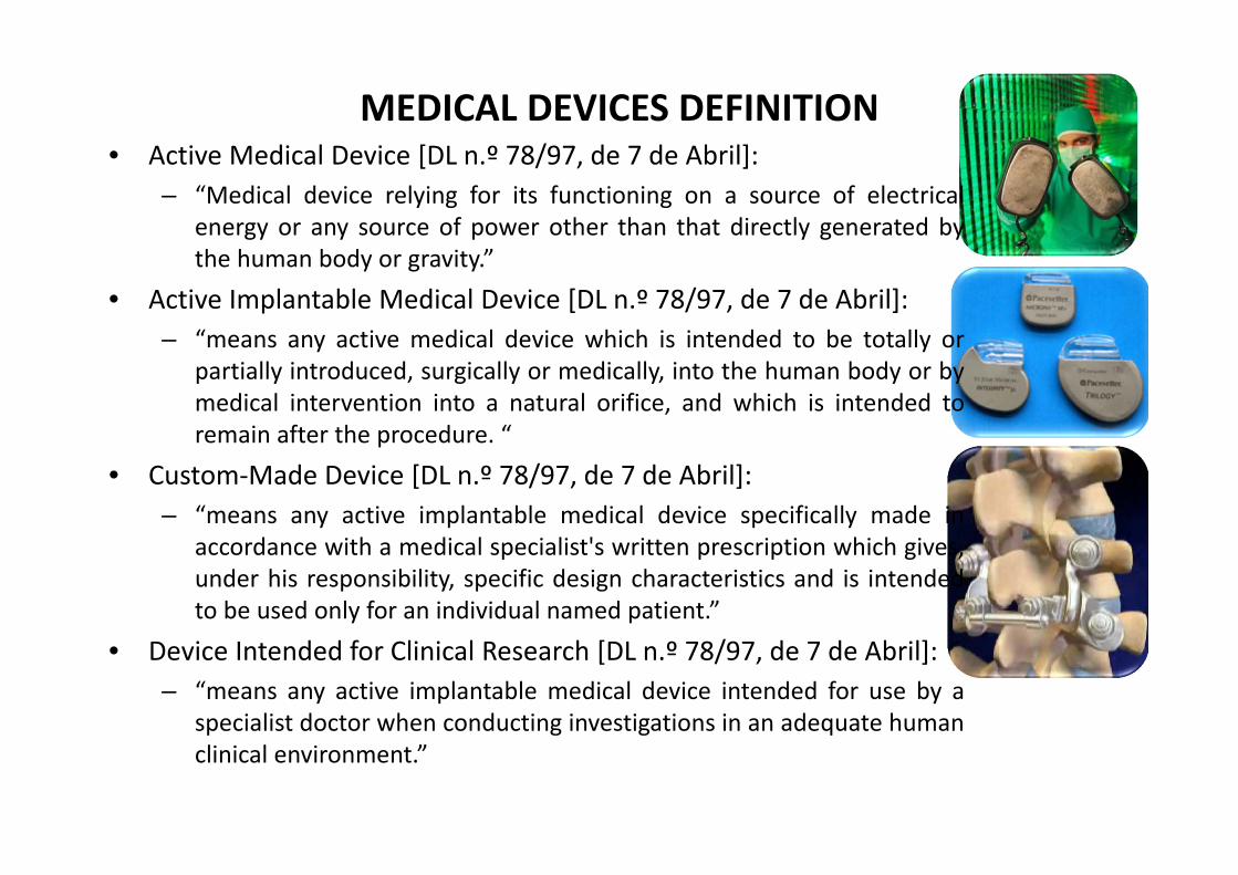
MEDICAL DEVICES DEFINITION• Active Medical Device [DL n.º 78/97, de 7 de Abril]:
– “Medical device relying for its functioning on a source of electricalenergy or any source of power other than that directly generated bythe human body or gravity.”
• Active Implantable Medical Device [DL n.º 78/97, de 7 de Abril]:– “means any active medical device which is intended to be totally or
partially introduced, surgically or medically, into the human body or bymedical intervention into a natural orifice, and which is intended toremain after the procedure. “
• Custom‐Made Device [DL n.º 78/97, de 7 de Abril]:– “means any active implantable medical device specifically made in
accordance with a medical specialist's written prescription which gives,under his responsibility, specific design characteristics and is intendedto be used only for an individual named patient.”
• Device Intended for Clinical Research [DL n.º 78/97, de 7 de Abril]:– “means any active implantable medical device intended for use by a
specialist doctor when conducting investigations in an adequate humanclinical environment.”
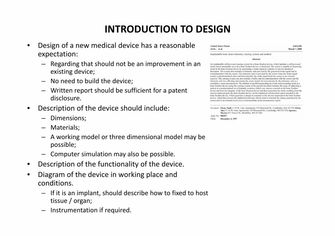
INTRODUCTION TO DESIGN• Design of a new medical device has a reasonable
expectation:– Regarding that should not be an improvement in an
existing device;– No need to build the device;– Written report should be sufficient for a patent
disclosure.• Description of the device should include:
– Dimensions;– Materials;– A working model or three dimensional model may be
possible;– Computer simulation may also be possible.
• Description of the functionality of the device.• Diagram of the device in working place and
conditions.– If it is an implant, should describe how to fixed to host
tissue / organ;– Instrumentation if required.
INTRODUCTION TO DESIGN• Engineering:
– Allows product development using knowledge.
• Science:– Process of acquiring new knowledge.
• Technology:– Means of producing the product.
• The problem of a missing organ:– Irreversible injury (destroys organ functionality);– Basic therapies for the missing organ (transplantation, passive implant,...);– Clinical problems that may have not been solved adequately.
• Design strategy (Prof. Myron Spector, Harvard Medical School:– Analyse problem of irreversible injured organ, identifying tissues in organs that
regenerate spontaneously (regenerative) and those that do not (non‐regenerative).– Designer should focus attention on non‐regenerative tissues, rather than planning
a new device to substitute the entire organ.

MEDICAL DEVICE DESIGN PROJECTS • Connective tissue:
– Musculoskeletal System:• Joint Replacement Prostheses:
– Ankle prosthesis;– Prosthesis for intervertebral disk regeneration .
• Fracture fixation device :– "Smart" bone plate.
• Bone Substitute Material;• Tendon/Ligament Replacement ;• Meniscus Replacement ;• Articular Cartilage Prosthesis.
– Oral, Maxillofacial, and Otologic:• Dental Implants;• Temporomandibular Joint Prostheses;• Ossicular Replacement Prostheses;• Augumentation of Gingiva.
– Cardiovascular System:• Angioplasty Balloon Catheter;• Heart Valve;• Vascular Prosthesis.

APPLICATIONS OF MEDICAL DEVICES
Medical devices for clinical purposes Number used per year in USA
Number used per year in PortugalRegistry started June 2009
Population 303 007 997 10 617 575
Orthopedic Hips (THA) 200 000 (?,SPOT) 10 000
Knees (TKA) 60 000 (?,SPOT) 12 000
Shoulders, finger joints 50 000 (?)
Reconstructive Breast prostheses 100 000 (?)
Dental 20 000 (?)
Cardiovascular Pacemakers 130 000 (?)

ERAS OF MEDICAL DEVICES
• 1920‐1970:– Age of new devices:
• Fracture fixation;• Joint replacement;• Spine Instrumentation.
• 1970‐– Age of Biomaterials:
• Bone graft subsitute materials.
• 2000‐– Age of Tissue Engineering:
• Porous absorbable materials to be seeded with cells.
• 2010‐– Age of Gene Terapy (?):
• Materials as delivery systems for genes.

PASSIVE IMPLANTS (PROSTHESIS / ORTHOTICS)
• Metallic's / plastics /ceramics are often used in device fabrication.
• Devices will play or not a long term function with host.
• Problems when host attacks implant:– Migration of prosthesis;– Abrasion of materials;– Tissue fluid may attacks electronic
devices.
• Problems when implant attacks host:– Bone loss cause by stress shielding
(According to Wolff's law, as a result of removal of normal stress from the bone by an implant).
DEFINITIONS
• Implant:– A device that is placed into a surgically or naturally formed cavity of the
human body if it is intended to remain there for a period of 30 days or more.
• Tissue:– An aggregation of similarly specialized cells united in the performance of a
particular function. Cells serving the same general function and having thesame extracellular matrix.
• Biomaterial:– Any substance (other than a drug) or combination of substances, synthetic or
natural in origin, which can be used at any period of time as a whole or in partof a system which treats, augments or place any tissue, organ or function ofthe body (J. W. Boretos and M. Eden, Contemporary Biomaterials, 1984 ).
– A non‐variable material used in a medical device intended to interact withbiological systems (D. F. Williams, Definitions of Biomaterials, 1987).

TISSUE TRIAD AND TISSUE REGENERATION• Epithelia:
– 100 % cells, no matrix, No blood vessels.
• Basement membrane:– No cells, 100 % matrix, No blood vessels.
• Stroma (connective tissue):– Cells, Matrix, Blood vessels.
The dermis is nonregenerative:LEFT: Excision of the epidermis and dermis to itsfull thickness. RIGHT: Wound edges contract andclose, while scar tissue forms.Stroma is not synthetized from remaining cells.
The epidermis is regenerative:LEFT: a controlled injury (e.g. stripping orblistering) which leaves the dermis intact.RIGHT : the epidermis recovers completely atthe defect site. Hair follicles are lined withepidermal tissue and also regenerate.Epithelia and basement membrane aresynthesized from remaining epithelia cells.

TISSUE REGENERATION• In vivo and in vitro tissue synthesis:

TISSUE AND ORGAN• Tissue is defined as:
– Biological structure made up of cells of thesame type:
• Cells of the same phenotype (same genesexpressed);
• An aggregation of morphologically similarcells and associated extracellular matrixacting together to perform on or morespecific functions in the body.
– There are 4 basic types of tissue: muscle,nerve, epithelia and connective.
• Organ is defined as:– Any structure made up of 2 or more tissues.
• Example:– Main tissue in the heart is the myocardium

TISSUE FORMATION PROCESSES
• Embryonic tissue formation.• Remodelling (degradation‐formation).• Healing (repair versus regeneration):
– Repair: defect in the tissue fills with “scar” (generally fibrous tissue) – Regeneration: defect fills with tissue that is indistinguishable from the original
tissue.• Factors that can prevent regeneration:
– Size of defect (eg: bone does not regenerate in large defects);– Collapse of the surrounding tissue (eg: periodontal defects);– Excessive strains in the reparative tissue (eg: unstable fractures).
• Response to permanent and absorbable implants:– Tissue formation in the gap (micrometer scale) between the implant and
surrounding host tissue;– Tissue formation in pores of porous implants.
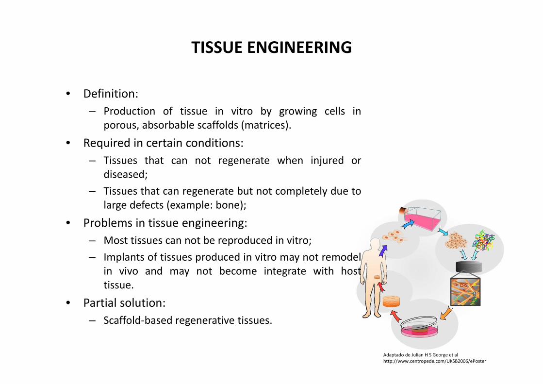
TISSUE ENGINEERING
• Definition:– Production of tissue in vitro by growing cells in
porous, absorbable scaffolds (matrices).
• Required in certain conditions:– Tissues that can not regenerate when injured or
diseased;– Tissues that can regenerate but not completely due to
large defects (example: bone);
• Problems in tissue engineering:– Most tissues can not be reproduced in vitro;– Implants of tissues produced in vitro may not remodel
in vivo and may not become integrate with hosttissue.
• Partial solution:– Scaffold‐based regenerative tissues.
Adaptado de Julian H S George et alhttp://www.centropede.com/UKSB2006/ePoster

TISSUE ENGINEERING MILESTONES
• 1980 : Yannas, Artificial skin. • 1984 : Wolter and Meyer, first use of tissue engineering.• 1991 : Cima and Vacanti and Langer, Chondrocytes in a polyglycolic acid
scaffold.• 1993 : Langer and Vacanti, Scientific paper on Tissue Engineering; cells in
matrices for tissue formation in vitro.• 1994 : Brittberg and Peterson, Carticel.
Step 1: Biopsy.Medical assessment of the extent of cartilage damage.
Step 2: Implantation .Medical incision to expose knee and remove any dead or damaged tissue from the injury.
Step 2: Implantation .Removal of a small piece of tissue from shin bone and sews it securely over the injury.
Step 2: Implantation .Medical injection of CARTICEL under the patch.
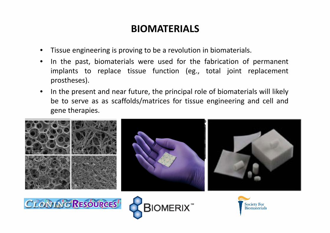
BIOMATERIALS
• Tissue engineering is proving to be a revolution in biomaterials.• In the past, biomaterials were used for the fabrication of permanent
implants to replace tissue function (eg., total joint replacementprostheses).
• In the present and near future, the principal role of biomaterials will likelybe to serve as as scaffolds/matrices for tissue engineering and cell andgene therapies.
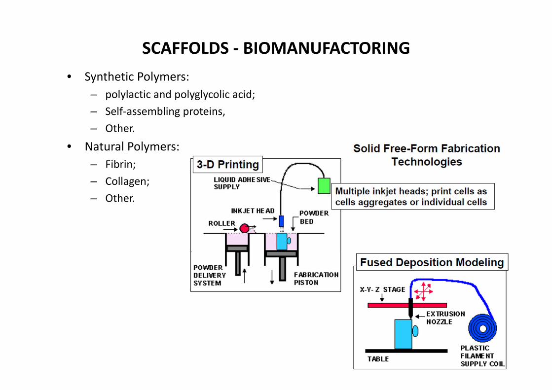
SCAFFOLDS ‐ BIOMANUFACTORING• Synthetic Polymers:
– polylactic and polyglycolic acid;– Self‐assembling proteins,– Other.
• Natural Polymers:– Fibrin;– Collagen;– Other.
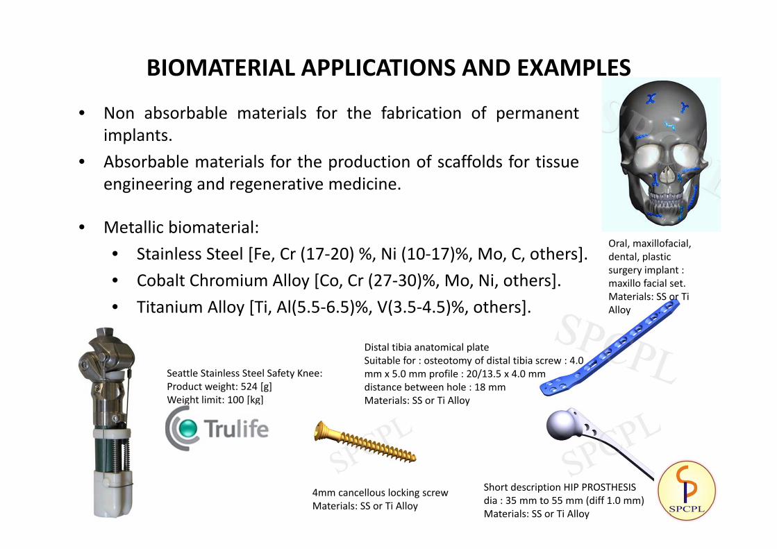
BIOMATERIAL APPLICATIONS AND EXAMPLES
• Non absorbable materials for the fabrication of permanentimplants.
• Absorbable materials for the production of scaffolds for tissueengineering and regenerative medicine.
• Metallic biomaterial:• Stainless Steel [Fe, Cr (17‐20) %, Ni (10‐17)%, Mo, C, others].• Cobalt Chromium Alloy [Co, Cr (27‐30)%, Mo, Ni, others].• Titanium Alloy [Ti, Al(5.5‐6.5)%, V(3.5‐4.5)%, others].
Seattle Stainless Steel Safety Knee:Product weight: 524 [g]Weight limit: 100 [kg]
Distal tibia anatomical plate Suitable for : osteotomy of distal tibia screw : 4.0 mm x 5.0 mm profile : 20/13.5 x 4.0 mm distance between hole : 18 mmMaterials: SS or Ti Alloy
4mm cancellous locking screwMaterials: SS or Ti Alloy
Short description HIP PROSTHESIS dia : 35 mm to 55 mm (diff 1.0 mm)Materials: SS or Ti Alloy
Oral, maxillofacial, dental, plasticsurgery implant : maxillo facial set.Materials: SS or Ti Alloy

BIOMATERIAL APPLICATIONS AND EXAMPLES
• Stainless steel plate for fracture fixation of proximal tibia– Ductility is important , because plate must be deformed in
the operating room, to conform the bone shape.
• Pure titanium fixation plate for distal fractures of the radius.
• Fracture of the distal tibia and fibula fixed by a single plate on each bone
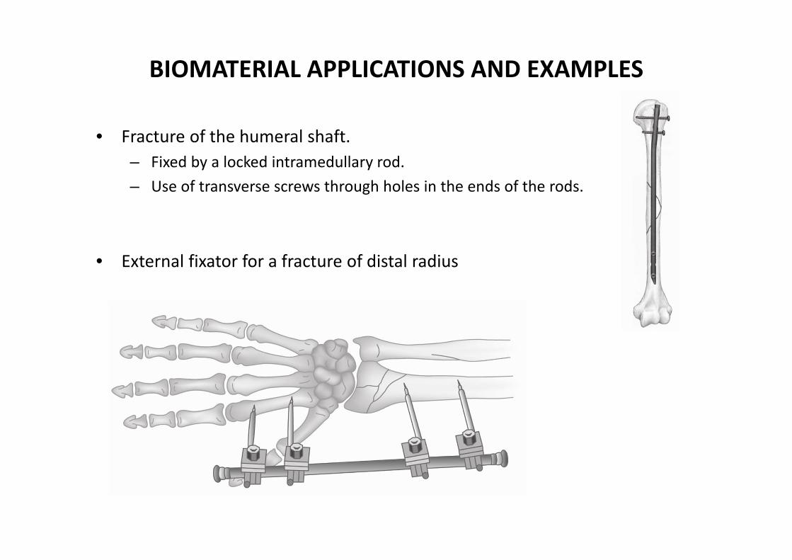
BIOMATERIAL APPLICATIONS AND EXAMPLES
• Fracture of the humeral shaft.– Fixed by a locked intramedullary rod.– Use of transverse screws through holes in the ends of the rods.
• External fixator for a fracture of distal radius
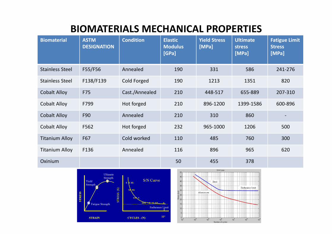
BIOMATERIALS MECHANICAL PROPERTIESBiomaterial ASTM
DESIGNATIONCondition Elastic
Modulus[GPa]
Yield Stress[MPa]
Ultimate stress[MPa]
Fatigue Limit Stress[MPa]
Stainless Steel F55/F56 Annealed 190 331 586 241‐276
Stainless Steel F138/F139 Cold Forged 190 1213 1351 820
Cobalt Alloy F75 Cast./Annealed 210 448‐517 655‐889 207‐310
Cobalt Alloy F799 Hot forged 210 896‐1200 1399‐1586 600‐896
Cobalt Alloy F90 Annealed 210 310 860 ‐
Cobalt Alloy F562 Hot forged 232 965‐1000 1206 500
Titanium Alloy F67 Cold worked 110 485 760 300
Titanium Alloy F136 Annealed 116 896 965 620
Oxinium 50 455 378

CERAMIC BIOMATERIAL• Most comoun ceramics:
– Alumina (aluminum oxide);– Zirconia (zirconium oxide);– Oxinium (recent developed material; new metal
alloy (zirconium‐Niobium) that presents a ceramic surface, produced by an oxidation process).
• Advantages:– Dense and hard (good against scratch resistance);– High quality external surface.
Fixed Partial Denture
Oxinium knee

BIOMECHANICS OF MATERIALS
• Anisotropic– Mechanical properties dependent upon direction of loading.– Bone is anisotropic ‐ its modulus is dependent upon the direction of loading.– Bone is weakest in shear, then tension, then compression.– Ultimate Stress at Failure Cortical Bone:
• Compression < 212 N/m2• Tension < 146 N/m2• Shear < 82 N/m2
• Viscoelastic– Stress‐Strain character dependent upon rate of applied strain (time
dependent).– Ex: Ligaments.

INTRODUCTION TO DESIGN• FAILURE, COLLAPSE:
– Load to Failure• Continuous application of force until the material breaks (failure point at the
ultimate load, ULS).• Common mode of failure of bone and reported in the implant literature.
– Fatigue Failure• Cyclical sub‐threshold loading may result in failure due to fatigue.• Common mode of failure of orthopaedic implants and fracture fixation constructs.
Browner et al: Skeletal Trauma 2nd Ed,Saunders, 1998.

BIOMECHANICS OF FRACTURES AND FIXATION
• Fracture mechanics:– Bending load: As compression resistance is grater than tension, bone fails in
tension
– Torsion: The diagonal in the direction of the applied force is in tension – cracks perpendicular to this tension diagonal. Spiral fracture 45º to the long axis
Tencer. Biomechanics in Orthopaedic
Trauma, Lippincott, 1994.

BIOMECHANICS OF FRACTURES AND FIXATION
• Fracture mechanics:– Bending and axial load: Leads to oblique fracture and Butterfly fragment
Tencer. Biomechanics in OrthopaedicTrauma, Lippincott, 1994.

BIOMECHANICS OF FRACTURES AND FIXATION• Function of the plate:
– Internal splint and Compression.
• Unstable constructs: – May lead to severe fragmentation, bone loss, poor quality bone and poor
screw technique.
• Fracture Gap:– Allows bending of plate with applied loads.– Fatigue failure. Even stable constructs may fail from fatigue if the fracture does
not heal due to biological reasons. Load
Bone Plate
Gap

BIOMECHANICS OF FRACTURES AND FIXATION
• The screws closest to the fracture see the most forces.• The construct rigidity decreases as the distance between the innermost
screws increases.• Number of screws (cortices) recommended on each side of the fracture:
– Forearm 3 (5‐6)– Humerus 3‐4 (6‐8)– Tibia 4 (7‐8)– Femur 4‐5 (8)
Screw Axial Force

BIOMECHANICS OF EXTERNAL FIXATION• Pin Size
– Radius. Most significant factor in frame stability.
• Number of Pins– Two per segment. Third pin: (C) out of plane of two other pins (A & B) stabilizes that
segment.
• Pin Location– Avoid zone of injury or future ORIF, Pins close to fracture as possible. Pins spread far
apart in each fragment.
A
B
C

BIOMECHANICS OF EXTERNAL FIXATION
• Pin Bending Preload:– Bending preload not recommended
• Radial preload (predrill w/ drill < inner diameter or tapered pin) – may decrease loosening and increase fixation
• Increase stability by:– Increasing the pin diameter;– Increasing the number of pins;– Increasing the spread of the pin;– Multi‐planar fixation;– Reducing the bone‐frame distance;– Pre‐drilling and cooling (reduces thermal necrosis, due to drilling process, the
surrounding bone tissue is heated, and when this temperatures exceeds critical limit, this may result in thermal necrosis, which means the irreversible death of the bone cells exposed to that high temperature);
– Radially preload pins,– 90º tensioned wires;– Stacked frames.
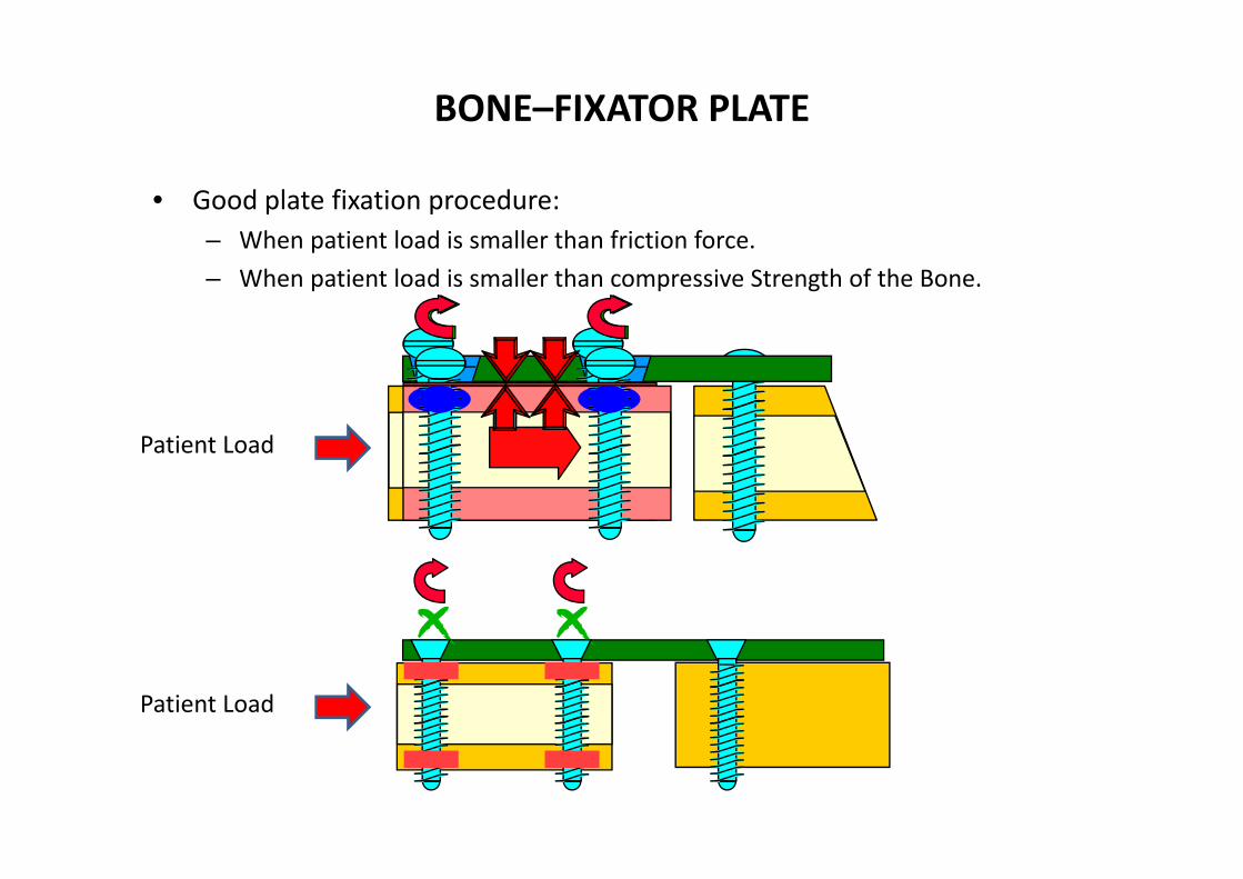
BONE–FIXATOR PLATE
• Good plate fixation procedure:– When patient load is smaller than friction force.– When patient load is smaller than compressive Strength of the Bone.
Patient Load
Patient Load

ADVANTAGES OF LOCKED PLATE FIXATION• Purchase of screws to bone not critical (osteoporotic bone).• Preservation of periosteal blood supply.• Strength of fixation rely on the fixed angle construct of screws to plate.
Conventional plating Loced plating
• Conventional plating:– Bone is pre‐stressed;– Periosteum strangled.– Contour of plate is important to
maintain anatomic reduction• Locked plating:– Plate (not bone) is pre‐stressed;– Periosteum preserved.– Contour of plate not as important.– Reduce fracture prior to applying
locking screws.

ANALYSIS OF INTERNAL FIXATION OF A FRACTURED BONE BY MEANS OF BONE–FIXATOR PLATE
• Introduction and Scope:– Fracture‐fixed long bones are submitted to axial load and bending loads,
due to eccentricity. This last load tends to open fracture, leading to thereduction in the stability of the fixation.
– Analytical model to predict forces to be applied in the screws, stressesin the bone and plate.
– Optimal plate selection to minimize deformation of the fractured bone,as well as introducing stress shielding into account.
– Advanced calculation method (FEA) to analyze stiffness graded plate,against homogeneous stiffness, to determine the extent of increasedstress shielding.
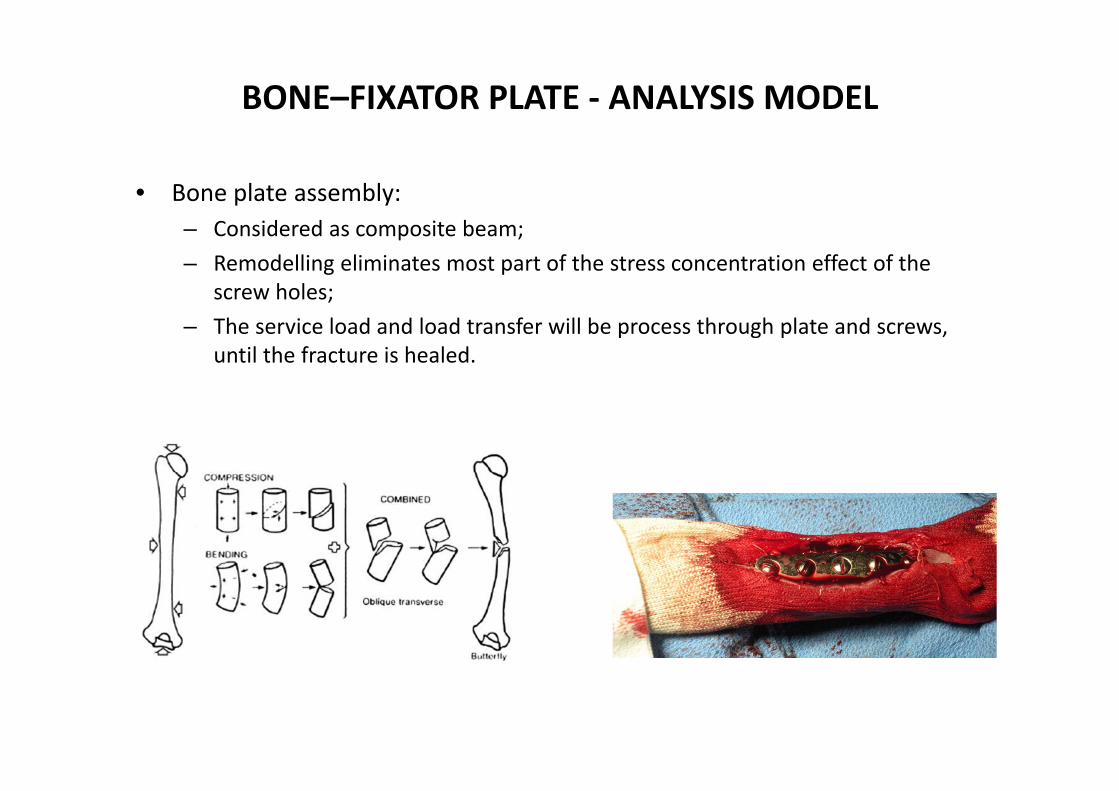
BONE–FIXATOR PLATE ‐ ANALYSIS MODEL
• Bone plate assembly:– Considered as composite beam;– Remodelling eliminates most part of the stress concentration effect of the
screw holes;– The service load and load transfer will be process through plate and screws,
until the fracture is healed.

BONE–FIXATOR PLATE ‐ LOADS• Bone: Weak in tension, strengthen in compression.• Loads: Service load produces internal forces: Normal, bending, torsion and
shear.• Load case 1 (axial load), Perfect Bond between the Bone and the Plate :
– Assume axial force P;– Space between screws equal to s;
– Free body diagram, assuming that screws a and b do not bend:• Q2 is part of the load P diverted by screw “a”;• Q1 is the remainder force deliver by the plate, through screw “b” to the bone.
Q2Q1
21 QQP
db
Q2Q1 P

BONE–FIXATOR PLATE – STRAIN COMPATIBILITY• The internal forces applied by the screws on bone:
– If the axial strain in the plate and the bone segments is such that the screw is not deformed by the bending moments exerted on it;
– The plate and the bone are deemed to be firmly held together;– Assuming strain calculation of uniform element as function of the cross‐section
area A, and elastic modulus E, when subjected to axial force F:
– The following conditions verifies:
AEF
L
bp

BONE–FIXATOR PLATE – STRAIN COMPATIBILITY
• Strain compatibility for bone–plate assembly under uniaxialtensile=compressive load :– Allows to determine internal forces, as function of an non‐dimensional cross
section and non‐dimensional elastic modulus.
EAEA
PQ
EAEA
EAEA
PQ
EAQ
EAQ
bb
pp
bb
pp
bbppbp
11
1121
ppbb
ppbp EAEA
EAPQ
1
• From graphical representation of the lastequation :– The proportion of force P diverted by screw “a”
into the bone depends on non‐dimensionalarea and elastic modulus;
– The load transferred by the screws isindependent from their spacing “s”.
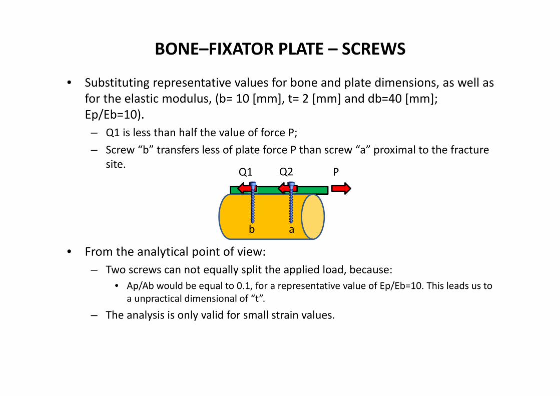
BONE–FIXATOR PLATE – SCREWS
• Substituting representative values for bone and plate dimensions, as well as for the elastic modulus, (b= 10 [mm], t= 2 [mm] and db=40 [mm]; Ep/Eb=10).– Q1 is less than half the value of force P;– Screw “b” transfers less of plate force P than screw “a” proximal to the fracture
site.
• From the analytical point of view:– Two screws can not equally split the applied load, because:
• Ap/Ab would be equal to 0.1, for a representative value of Ep/Eb=10. This leads us to a unpractical dimensional of “t”.
– The analysis is only valid for small strain values.
Q2Q1 P
ab
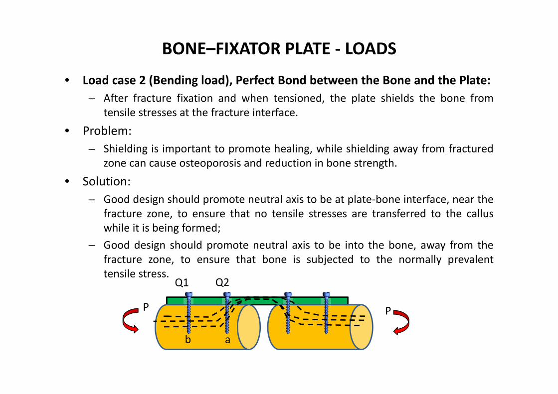
BONE–FIXATOR PLATE ‐ LOADS
• Load case 2 (Bending load), Perfect Bond between the Bone and the Plate:– After fracture fixation and when tensioned, the plate shields the bone from
tensile stresses at the fracture interface.
• Problem:– Shielding is important to promote healing, while shielding away from fractured
zone can cause osteoporosis and reduction in bone strength.
• Solution:– Good design should promote neutral axis to be at plate‐bone interface, near the
fracture zone, to ensure that no tensile stresses are transferred to the calluswhile it is being formed;
– Good design should promote neutral axis to be into the bone, away from thefracture zone, to ensure that bone is subjected to the normally prevalenttensile stress.
Q2Q1
P
ab
P
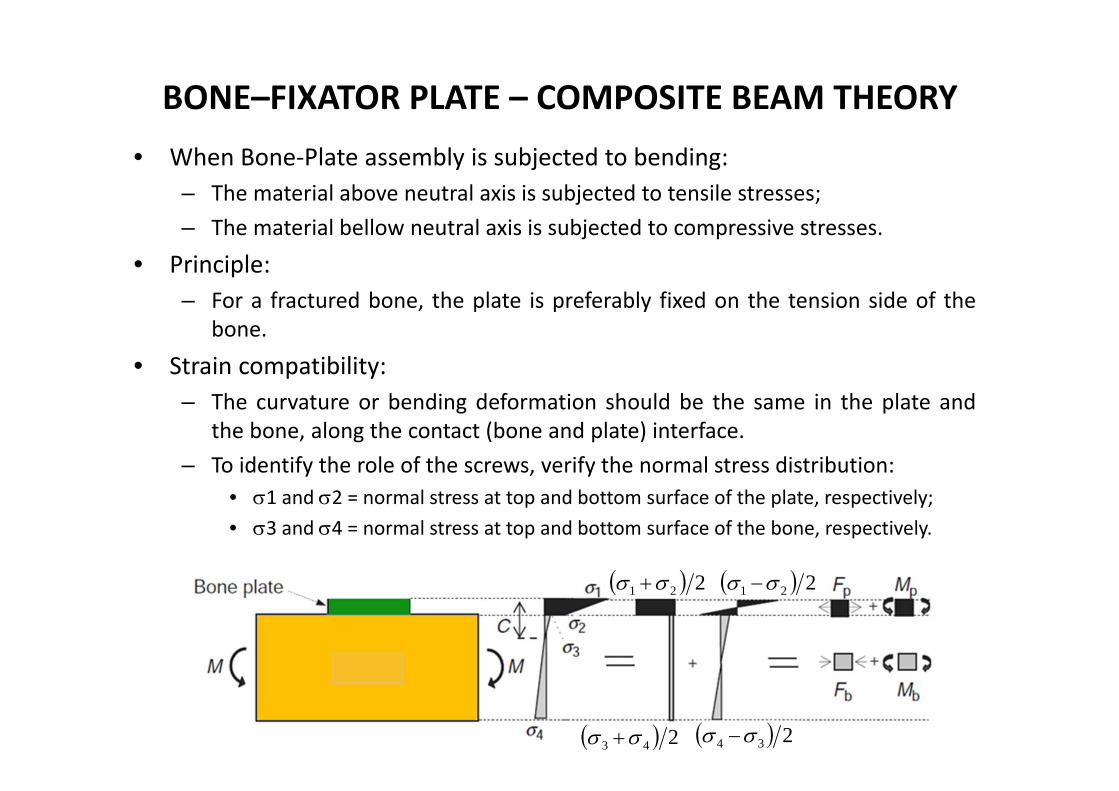
BONE–FIXATOR PLATE – COMPOSITE BEAM THEORY• When Bone‐Plate assembly is subjected to bending:
– The material above neutral axis is subjected to tensile stresses;– The material bellow neutral axis is subjected to compressive stresses.
• Principle:– For a fractured bone, the plate is preferably fixed on the tension side of the
bone.
• Strain compatibility:– The curvature or bending deformation should be the same in the plate and
the bone, along the contact (bone and plate) interface.– To identify the role of the screws, verify the normal stress distribution:
• 1 and 2 = normal stress at top and bottom surface of the plate, respectively;• 3 and 4 = normal stress at top and bottom surface of the bone, respectively.
221 221
243 234
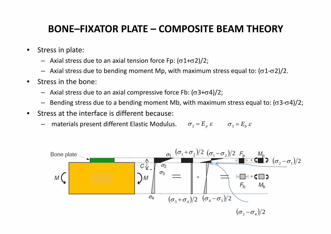
BONE–FIXATOR PLATE – COMPOSITE BEAM THEORY
• Stress in plate:– Axial stress due to an axial tension force Fp: (1+2)/2;– Axial stress due to bending moment Mp, with maximum stress equal to: (1‐2)/2.
• Stress in the bone:– Axial stress due to an axial compressive force Fb: (3+4)/2;– Bending stress due to a bending moment Mb, with maximum stress equal to: (3‐4)/2;
• Stress at the interface is different because:– materials present different Elastic Modulus.
221 221
243
243 234
212
pE2 bE3

COMPOSITE BEAM THEORY• Composite beam with two different materials:
– A) Generic cross‐section ;– B) Normal strain distribution;– C) Normal stress distribution, case when E2>E1.
– Beam theory:
– Neutral axis:– Moment curvature relationship:
AA E 1
BB E 2 y
ykEx 11
ykEx 22
A) B) C)
000212121
221122112211 AAAAA
xA
x dAykEdAykEdAkyEdAkyEdAdA
)( 221122
212
12211
2121
IEIEkdAyEkdAyEkdAydAydAyMAAA
xA
xA
x
)( 2211 IEIEMk
1st order moment of each area respect to neutral axis
0222111 AyEAyE
y1
y2C
I J
M N
I’ J’
M N
y
kyyIJ
IJJIx
''
)('' yJI
MN

BONE–FIXATOR PLATE – COMPOSITE BEAM THEORY
• Normal stresses for composite beams (theory):
• For the case of bone‐fixator plate:
– At contact level, stresses are different because the elastic modulus are different;– Y1 represents the distance between neutral axis and the centre of the plate;– Y2 represents the distance between neutral axis and the centre of the bone.
''1bbpp
p
IEIECME
''2
)(
bbpp
p
IEIEtCME
''3)(
bbpp
b
IEIEtCME
''4
)(
bbpp
bb
IEIECtdME
221 221
243 243
221111 IEIE
MyEkyEA
221122 IEIE
MyEkyEB
22
'
21
'
yAII
yAII
bbb
ppp

BONE–FIXATOR PLATE – COMPOSITE BEAM THEORY• Moments and axial forces shared by the plate and bone may be
calculated according to:– Plate:
– Bone:
tdIEIEtCME
AF pbbpp
ppp )(2
22 ''
11
'''
'
''
'21
)(2
)(22
2 pbbpp
pp
bbpp
ppp I
IEIEME
tI
IEIEtME
tI
M
22''
43
4)(222
2 iebbpp
ebbb DD
IEIEDtCMEAF
'''
'
''
'43
)(2
)(2)(
22 b
bbpp
b
e
b
bbpp
eb
e
bb I
IEIEME
DI
IEIEDME
DIM
ØDe
ØDi
dp
t
d1
Lp
a a
+
-
N.A.
y2y1
c
L
122
AE
DettAEC
‐ Neutral axis:
0)2
()2
(
0
be
bpp
bbbppp
ACtDEAtCE
AyEAyE
SECOND ORDER BEAM THEORY
• Second Order Theory of Deflections for the Linear Elastic Isotropic Beams– the second order theory enables to include directly the influence of the
normal forces along the beam on its deflection function.– From the mathematical point of view, the differential equation adequate to
the deflection function is written on the deformed configuration of this beam,so that the normal forces can play significant role in the beam strength.
• For more information, please read information about in maple software ‐application center ‐ user community
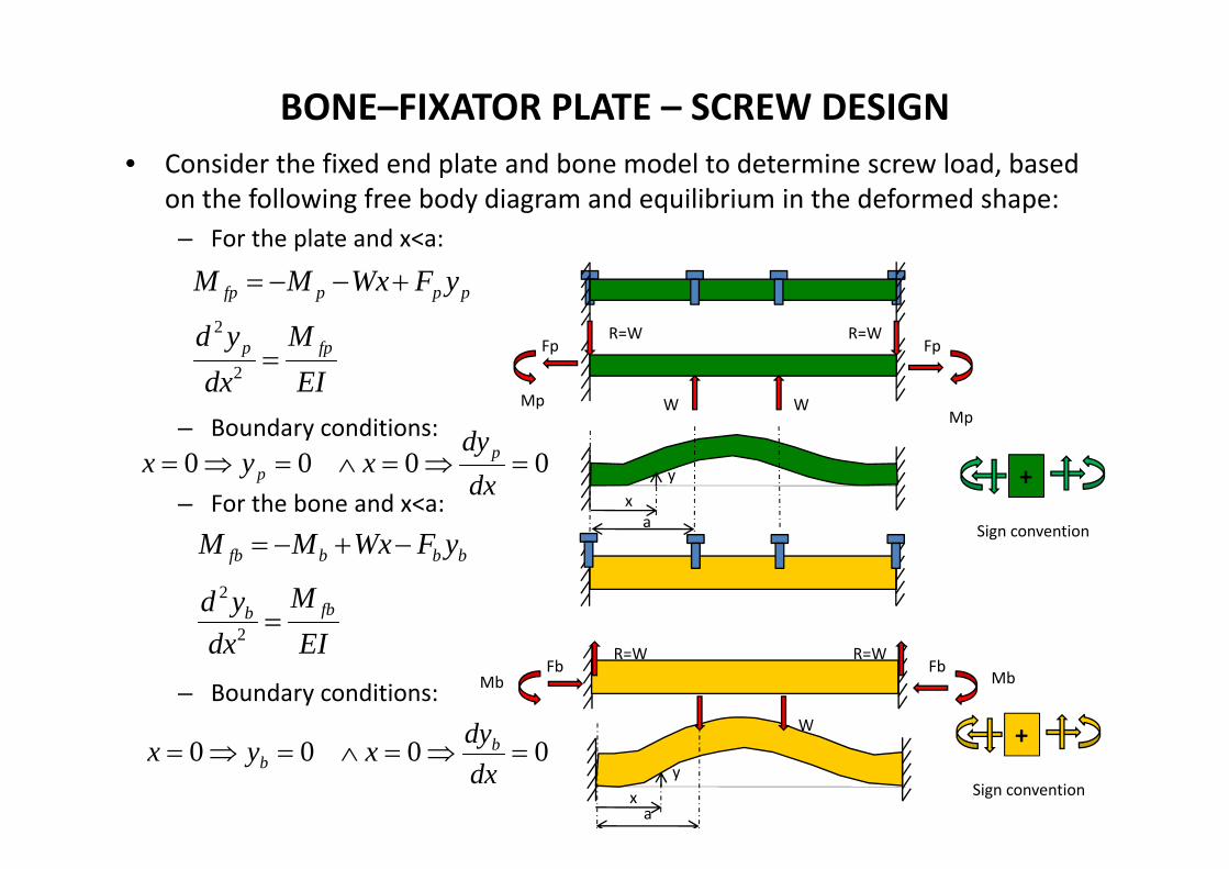
BONE–FIXATOR PLATE – SCREW DESIGN• Consider the fixed end plate and bone model to determine screw load, based
on the following free body diagram and equilibrium in the deformed shape:– For the plate and x<a:
– Boundary conditions:
– For the bone and x<a:
– Boundary conditions:
R=W
W W
R=WFp Fp
MpMp
xa
y +
Sign convention
pppfp yFWxMM
EIM
dxyd fpp 2
2
0000 dxdy
xyx pp
bbbfb yFWxMM
EIM
dxyd fbb 2
2
0000 dxdyxyx b
b+
Sign conventionxy
a
R=W
W
R=WFb Fb
Mb Mb
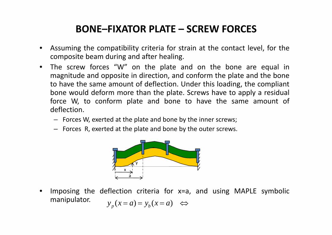
BONE–FIXATOR PLATE – SCREW FORCES
• Assuming the compatibility criteria for strain at the contact level, for thecomposite beam during and after healing.
• The screw forces “W” on the plate and on the bone are equal inmagnitude and opposite in direction, and conform the plate and the boneto have the same amount of deflection. Under this loading, the compliantbone would deform more than the plate. Screws have to apply a residualforce W, to conform plate and bone to have the same amount ofdeflection.– Forces W, exerted at the plate and bone by the inner screws;– Forces R, exerted at the plate and bone by the outer screws.
• Imposing the deflection criteria for x=a, and using MAPLE symbolicmanipulator.
xy
a
)()( axyaxy bp

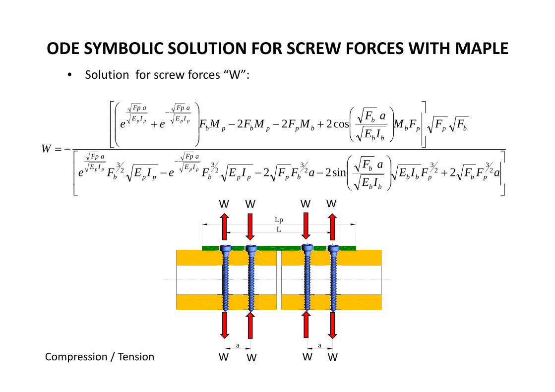
ODE SYMBOLIC SOLUTION FOR SCREW FORCES WITH MAPLE
• > restart;• > M := M;• > Eb := Ebc;• > Ep := Ep;• > Et := Ep/Eb;• > De := De;• > Di := Di;• > t := t;• > dp := dp;• > Ip := Ip;• > Ap := dp*t;• > Ab := Ab;• > d1 := (1/2)*De+(1/2)*t;• > At := Ap/Ab;• > Ib := Ib;• > It := Ip/Ib;• > C := (De+2t+AtEt*t)/(2*(At*Et+1));• > W := W;• > Ipl := Ip+dp*t*(C‐(1/2)*t)^2;• > Ibl := Ib+Pi*((1/4)*De^2‐(1/4)*Di^2)*(d1+(1/2)*t‐C)^2;
• > y1 := C‐(1/2)*t;• > y2 := d1+(1/2)*t‐C;• > Mp := Mp;• > Mb := Mb;• > Fp := Fp;• > Fb := Fb;• > a := a;• > > with(DETools);• > ode1 := Ep*Ip*(diff(diff(yp(x), x), x)) = ‐Mp‐W*x+Fp*yp(x);• > dsolve({ode1, yp(0) = 0, (D(yp))(0) = 0}, yp(x)); assign(%);• > solyp := eval(subs(x = a, yp(x)));• > ode2 := Eb*Ib*(diff(diff(yb(x), x), x)) = ‐Mb+W*x‐Fb*yb(x);• > dsolve({ode2, yb(0) = 0, (D(yb))(0) = 0}, yb(x)); assign(%);• > solyb := eval(subs(x = a, yb(x)));• > eqn := solyp = solyb;• > solve(eqn, W);
Lp
a a
L
ODE SYMBOLIC SOLUTION FOR SCREW FORCES WITH MAPLE• Solution for screw forces “W”:
aFFFIEIEaF
aFFIEFeIEFe
FFFMIEaF
MFMFMFee
W
pbpbbbb
bbpppb
IEaFp
ppbIEaFp
bppbbb
bbppbpb
IEaFp
IEaFp
pppp
pppp
23
23
23
23
23
2sin22
cos222
W W
W W
Compression / Tension W
W
W
W

BONE–FIXATOR PLATE: CONCLUSION
• Neutral axis should be located at the plate bone interface;• Normal stress at surface bone, underneath the plate, should be zero in the
callus (so that there is no tensile stress);• Stiffness of the plate should not be excessive, otherwise compressive
stresses will appear, due to the fact of having neutral axis inside the plate;

BONE–FIXATOR PLATE 4 SCREWS IN BENDING
• Working Project 1: – Assume plate in stainless steel material, with Ep=210 [GPa], width dp=15 [mm] ,
thickness t=2,3,4,5 [mm], Lp=60 [mm], – Assume bone healing process, with callus formation, around fracture. This means to
use Ebc=0,005 Eb , 50% Eb and 100% Eb. ( Eb=21 [GPa])– Load: M=1, 10, 20, 30 [Nm].– Calculate screw forces and axial stress S3, in callus zone (Z1) and away from callus
zone (Z2).– Assume a=10 [mm] and L= 60 [mm].
Ø24
Ø12
15
t
d1
Lp
a a
+
-
N.A.
y2y1
c
L
Z2 Z1
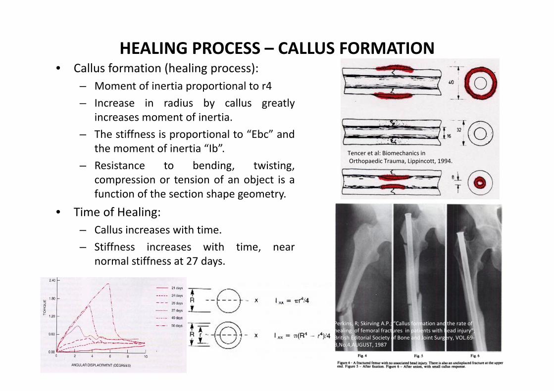
HEALING PROCESS – CALLUS FORMATION• Callus formation (healing process):
– Moment of inertia proportional to r4– Increase in radius by callus greatly
increases moment of inertia.– The stiffness is proportional to “Ebc” and
the moment of inertia “Ib”.– Resistance to bending, twisting,
compression or tension of an object is afunction of the section shape geometry.
• Time of Healing:– Callus increases with time.– Stiffness increases with time, near
normal stiffness at 27 days.
Tencer et al: Biomechanics inOrthopaedic Trauma, Lippincott, 1994.
Perkins, R; Skirving A.P.; “Callus formation and the rate of healing of femoral fractures in patients with head injury“; British Editorial Society of Bone and Joint Surgery, VOL.69‐B,No.4,AUGUST, 1987

BONE–FIXATOR PLATE 6 SCREWS IN BENDING• HOME WORK:
– Assume plate in stainless steel material, with Ep=210 [GPa], width plate moment of inertia Ip=156 [mm4] , thickness t=2,3,4,5 [mm], Lp=60 [mm],
– Assume bone healing process, with callus formation, around fracture. This means to use Ebc=0,005 Eb instead of Eb=21 [GPa].
– Load: M=1, 10, 20, 30 [Nm].– Calculate screw forces and axial stress S3, in callus zone (Z1) and away from
callus zone (Z2) and the optimal thickness of the plate.– Assume a=20 [mm] and b= 40 [mm].
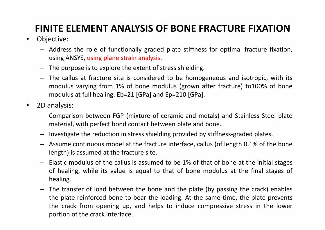
FINITE ELEMENT ANALYSIS OF BONE FRACTURE FIXATION• Objective:
– Address the role of functionally graded plate stiffness for optimal fracture fixation,using ANSYS, using plane strain analysis.
– The purpose is to explore the extent of stress shielding.– The callus at fracture site is considered to be homogeneous and isotropic, with its
modulus varying from 1% of bone modulus (grown after fracture) to100% of bonemodulus at full healing. Eb=21 [GPa] and Ep=210 [GPa].
• 2D analysis:– Comparison between FGP (mixture of ceramic and metals) and Stainless Steel plate
material, with perfect bond contact between plate and bone.– Investigate the reduction in stress shielding provided by stiffness‐graded plates.– Assume continuous model at the fracture interface, callus (of length 0.1% of the bone
length) is assumed at the fracture site.– Elastic modulus of the callus is assumed to be 1% of that of bone at the initial stages
of healing, while its value is equal to that of bone modulus at the final stages ofhealing.
– The transfer of load between the bone and the plate (by passing the crack) enablesthe plate‐reinforced bone to bear the loading. At the same time, the plate preventsthe crack from opening up, and helps to induce compressive stress in the lowerportion of the crack interface.
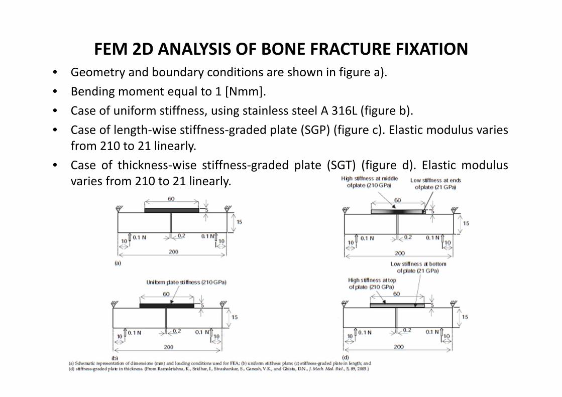
FEM 2D ANALYSIS OF BONE FRACTURE FIXATION• Geometry and boundary conditions are shown in figure a).• Bending moment equal to 1 [Nmm].• Case of uniform stiffness, using stainless steel A 316L (figure b).• Case of length‐wise stiffness‐graded plate (SGP) (figure c). Elastic modulus varies
from 210 to 21 linearly.• Case of thickness‐wise stiffness‐graded plate (SGT) (figure d). Elastic modulus
varies from 210 to 21 linearly.

FEM 2D ANALYSIS OF BONE FRACTURE FIXATION
• Working Project 2 ‐ Numerical model:– Use 4 node plain strain elements (ANSYS plane 182 with KEYOPT(1) = 3 );– Calculate axial stress distribution over the plate and bone, for callus zone Z1, for
progressive healing:• Early stages of healing. Ebc=1% Eb(=20 [GPa]). Neutral axis inside plate. Callus interface
is in compression.• As healing progresses, the Elastic modulus increases. Neutral axis shifts down into bone
material, allowing callus to bear tensile stresses.
– Testing cases:• Case 1 (Initial healing): Eb=20 [GPa], Ebc(1%)=0,2 [GPa], Ep=210 [GPa] (Ē=10,5).• Case 2 (Initial healing): Eb=20 [GPa], Ebc(1%)=0,2 [GPa], Ep=100 [GPa] (Ē=5).• Case 3 (Initial healing): Eb=20 [GPa], Ebc(1%)=0,2 [GPa], Ep=20 [GPa] (Ē=1).• Case 4 (progressive healing): Eb=20 [GPa], Ebc(50%)=10 [GPa], Ep=210 [GPa] (Ē=10,5).• Case 5 (progressive healing): Eb=20 [GPa], Ebc(50%)=10 [GPa], Ep=100 [GPa] (Ē=5).• Case 6 (progressive healing): Eb=20 [GPa], Ebc(50%)=10 [GPa], Ep=20 [GPa] (Ē=1).• Case 7 (final healing): Eb=20 [GPa], Ebc(100%)=20 [GPa], Ep=210 [GPa] (Ē=10,5).• Case 8 (final healing): Eb=20 [GPa], Ebc(100%)=20 [GPa], Ep=100 [GPa] (Ē=5).• Case 9 (final healing): Eb=20 [GPa], Ebc(100%)=20 [GPa], Ep=20 [GPa] (Ē=1).
FEM 2D ANALYSIS OF BONE FRACTURE FIXATION
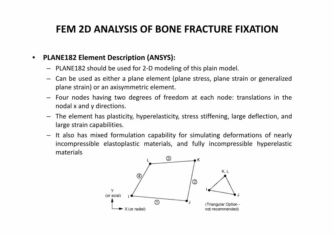
• PLANE182 Element Description (ANSYS):– PLANE182 should be used for 2‐D modeling of this plain model.– Can be used as either a plane element (plane stress, plane strain or generalized
plane strain) or an axisymmetric element.– Four nodes having two degrees of freedom at each node: translations in the
nodal x and y directions.– The element has plasticity, hyperelasticity, stress stiffening, large deflection, and
large strain capabilities.– It also has mixed formulation capability for simulating deformations of nearly
incompressible elastoplastic materials, and fully incompressible hyperelasticmaterials
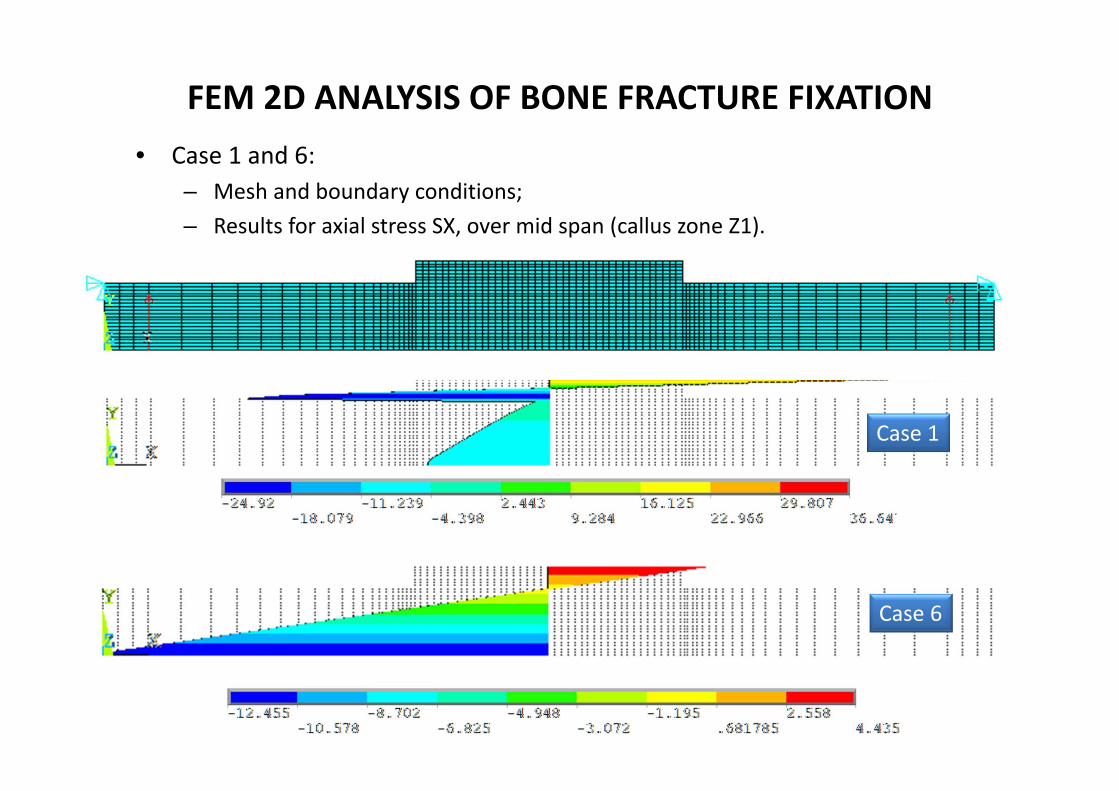
FEM 2D ANALYSIS OF BONE FRACTURE FIXATION• Case 1 and 6:
– Mesh and boundary conditions;– Results for axial stress SX, over mid span (callus zone Z1).
Case 6
Case 1
FEM 2D ANALYSIS OF BONE FRACTURE FIXATION
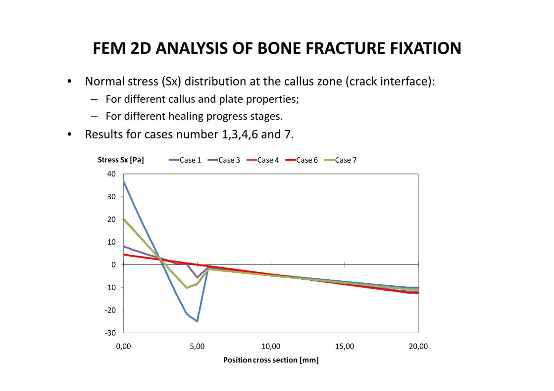
• Normal stress (Sx) distribution at the callus zone (crack interface):– For different callus and plate properties;– For different healing progress stages.
• Results for cases number 1,3,4,6 and 7.
‐30
‐20
‐10
0
10
20
30
40
0,00 5,00 10,00 15,00 20,00
Stress Sx [Pa]
Position cross section [mm]
Case 1 Case 3 Case 4 Case 6 Case 7

FEM 2D ANALYSIS OF BONE FRACTURE FIXATION
• Case 1 and 6: Results for axial stress SX, along bone plate interface.– Case 1: Initial healing process;– Case 6: 50 % healing process.
Case 6Case 1

FEM 2D ANALYSIS OF BONE FRACTURE FIXATION
• Normal stress (Sx) distribution along the bone‐plate interface:– It is observed that initially after fracture, all the three types of plates shield the
bone, by not allowing any tensile stress in the upper bone layers, close to the fracture interface.
‐30
‐25
‐20
‐15
‐10
‐5
0
5
10
15
0 0,01 0,02 0,03 0,04 0,05 0,06
Stress Sxx [Pa]
Length bone‐plate interface [m]
Case 1 Case 3 Case 4 Case 6 Case 7
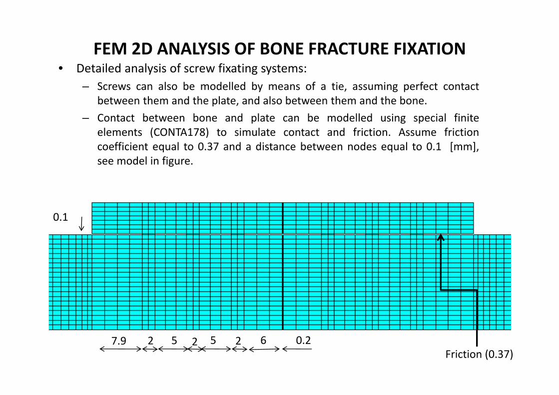
FEM 2D ANALYSIS OF BONE FRACTURE FIXATION• Detailed analysis of screw fixating systems:
– Screws can also be modelled by means of a tie, assuming perfect contactbetween them and the plate, and also between them and the bone.
– Contact between bone and plate can be modelled using special finiteelements (CONTA178) to simulate contact and friction. Assume frictioncoefficient equal to 0.37 and a distance between nodes equal to 0.1 [mm],see model in figure.
5 5 67.9 2 2 2 0.2
0.1
Friction (0.37)

FEM 2D ANALYSIS OF BONE FRACTURE FIXATION
• Case 1: Results for axial stress SX, along bone plate interface and partial domain.– Case 1: Initial healing process.
• Case 1: Results for axial stress SX, along callus– Case 1: Initial healing process.

FEM 2D ANALYSIS OF BONE FRACTURE FIXATION
• Conclusions:– The early stages of healing, the bone is almost de‐stressed at the fracture
zone.– Large variations of normal stresses are seen at the screw sites of the bone.– In the final stages of healing, the NA becomes relocated from the plate to
within the bone. At this stage, the screws are not playing such a major role inmaintaining the integrity of the bone, as in the early stages of healing.
– The screw location on the plate (rather than the stiffness of the plate) has amore dominating role in minimizing the stress‐shield zone.
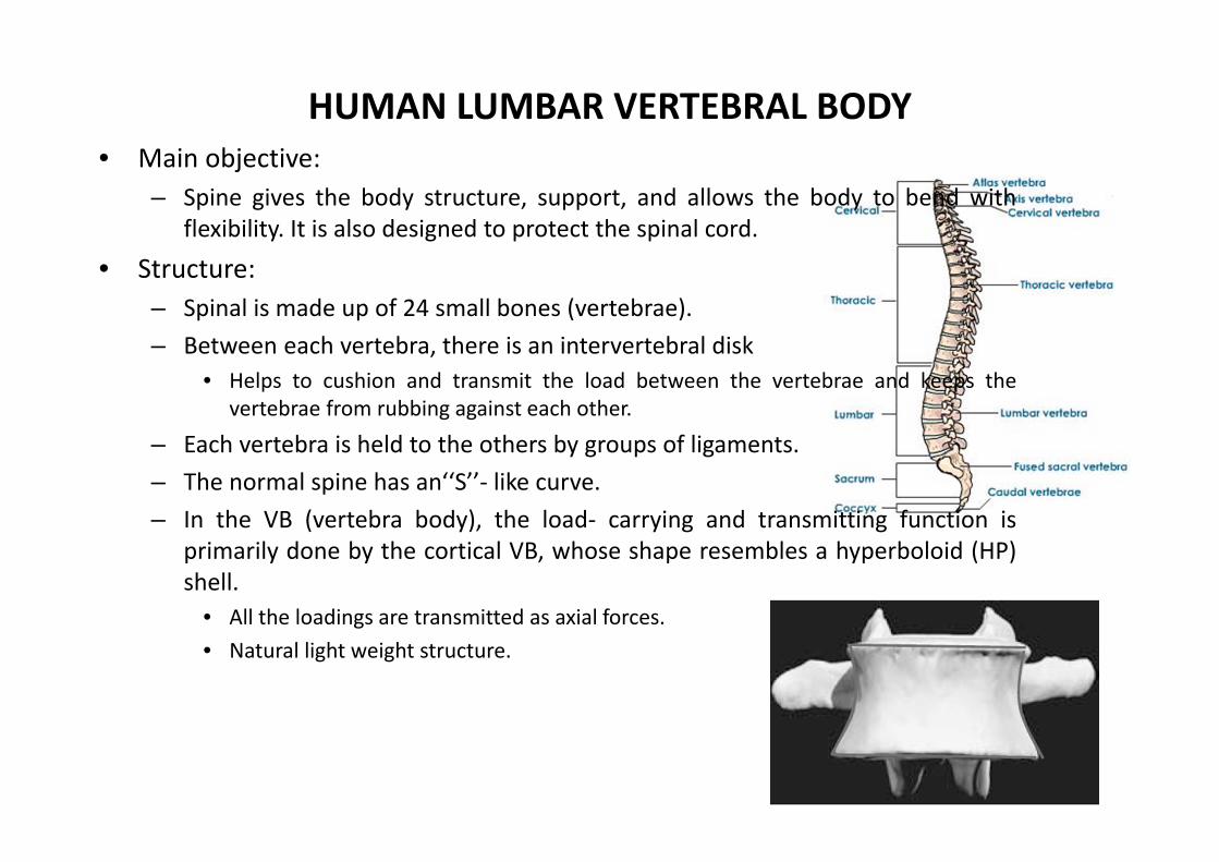
HUMAN LUMBAR VERTEBRAL BODY• Main objective:
– Spine gives the body structure, support, and allows the body to bend withflexibility. It is also designed to protect the spinal cord.
• Structure:– Spinal is made up of 24 small bones (vertebrae).– Between each vertebra, there is an intervertebral disk
• Helps to cushion and transmit the load between the vertebrae and keeps thevertebrae from rubbing against each other.
– Each vertebra is held to the others by groups of ligaments.– The normal spine has an‘‘S’’‐ like curve.– In the VB (vertebra body), the load‐ carrying and transmitting function is
primarily done by the cortical VB, whose shape resembles a hyperboloid (HP)shell.
• All the loadings are transmitted as axial forces.• Natural light weight structure.
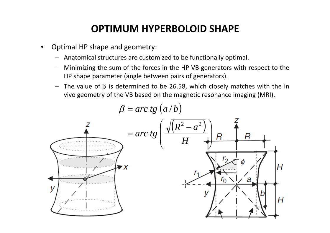
OPTIMUM HYPERBOLOID SHAPE
• Optimal HP shape and geometry:– Anatomical structures are customized to be functionally optimal.– Minimizing the sum of the forces in the HP VB generators with respect to the
HP shape parameter (angle between pairs of generators).– The value of is determined to be 26.58, which closely matches with the in
vivo geometry of the VB based on the magnetic resonance imaging (MRI).
HaR
tgarc
batgarc22
/

HYPERBOLOID SHAPE OF VERTEBRAL BODY
• Intersecting the HP shell surface with a vertical plane parallel to the yzplane but at x=‐a, then the intersecting curves are given by:
• The primary dimensional parameters of the VB HP are hence (R, a, and H).

MEMBRANE STRESSES IN THE VERTEBRAL BODY CORTEX• Use the membrane theory of shells to analyze the stresses in the cortical.• Membrane stresses:
– Meridian stress– Hoop stress.
• Under normal pressure:• Static equilibrium in radial direction for forces:
– R2 considered to be positive;– R1 considered to be negative.
• For small angle :
rp
232222
22
1cossin ba
bar
212222
2
2cossin ba
ar
02
sin22
sin2
2sin2
2sin2
21
12
drdrp
drtddrtd
r
2d
22sin dd
rpr
tr
t
21
2d
22sin dd

MEMBRANE STRESSES IN THE VERTEBRAL BODY CORTEX
• Assuming the concept of stress per unit of wall thickness:– Hoop force per unit of length:– Meridian force per unit of length:
• Equilibrium equation in “r” direction, becomes the membrane equation.
• If the internal pressure (pr) in the cancellus bone, within the cortical shell is negligible, the equation becomes:
• Substituting the geometric value of r1 and r2, , the relation becomes:
rprN
rN
21
NN
NrrN
2
1
32
421 rabr
NrabN
2
24
2

STRESS ANALYSIS UNDER COMPRESIVE FORCE
• Stress in shell cortex when submitted to compressive force “C”.– Force equilibrium in vertical direction holds, for any
horizontal section:
– For the case of waist circle (r0=a), which means =90º, the meridian and hoop force per unit of length are compressive in nature and equal to.
CrN 02sin
aCN 2
a
Ca
CbaN
baN
rbaN
2tan
21 2
2
2
2
2
22
2
4
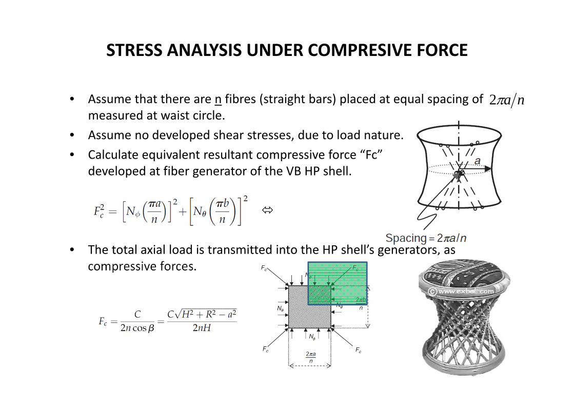
STRESS ANALYSIS UNDER COMPRESIVE FORCE
• Assume that there are n fibres (straight bars) placed at equal spacing of measured at waist circle.
• Assume no developed shear stresses, due to load nature.• Calculate equivalent resultant compressive force “Fc”
developed at fiber generator of the VB HP shell.
• The total axial load is transmitted into the HP shell’s generators, as compressive forces.
na2
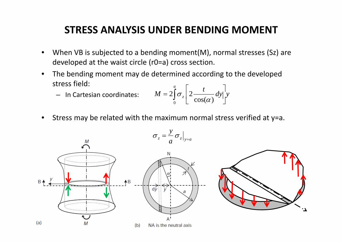
STRESS ANALYSIS UNDER BENDING MOMENT
• When VB is subjected to a bending moment(M), normal stresses (Sz) are developed at the waist circle (r0=a) cross section.
• The bending moment may de determined according to the developed stress field:– In Cartesian coordinates:
• Stress may be related with the maximum normal stress verified at y=a.
ydytMa
z
0 )cos(22
ayzz ay

STRESS ANALYSIS UNDER BENDING MOMENT
• Combining both last equations, the bending moment may be determined by:
• Assuming the change of integration variable:
• The bending moment may be rewritten:
• The meridian force per unit of length, at position y=a (waist circle):
a
a dya
ytM0
2
)cos(4
dady )cos()sin(ay
ataM 2
2aMtN aa
))cos()sin((21)(sin2 d

STRESS ANALYSIS UNDER BENDING MOMENT
• Calculate equivalent resultant compressive force “Fm” developed at fibergenerator of the VB HP shell:
• Upon substituting the Meridian force per unit of length:
• Since batg /
OBS: May be positive or negative

STRESS ANALYSIS UNDER TORSION MOMENT
• When VB is subjected to pure torsion, shear stresses are developed, while the normal stresses are equal to zero.– The Meridian force per unit of length and Hoop force per unit of length will
vanish.
• The equilibrium of a segment of the shell at a horizontal section gives:
• At the waist circle “r2”=“r0”=“a”:
• The equivalent resulting force system
OPTIMAL DESIGN
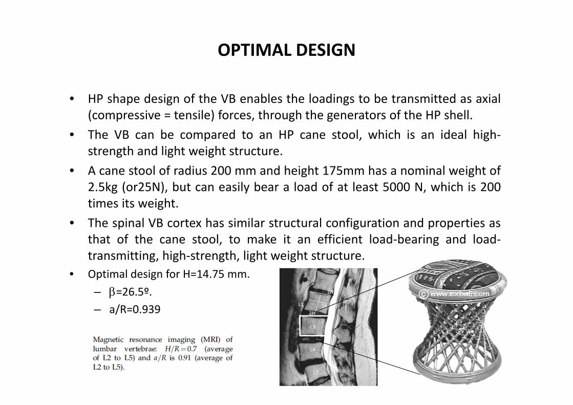
• HP shape design of the VB enables the loadings to be transmitted as axial(compressive = tensile) forces, through the generators of the HP shell.
• The VB can be compared to an HP cane stool, which is an ideal high‐strength and light weight structure.
• A cane stool of radius 200 mm and height 175mm has a nominal weight of2.5kg (or25N), but can easily bear a load of at least 5000 N, which is 200times its weight.
• The spinal VB cortex has similar structural configuration and properties asthat of the cane stool, to make it an efficient load‐bearing and load‐transmitting, high‐strength, light weight structure.
• Optimal design for H=14.75 mm.– =26.5º.– a/R=0.939

SURGICAL TREATMENT IN BURST FRACTURE
• Spinal VB fails if the load exceeds the sustainable limits.• Failure of the VB is very painful to the person, as the fractured VB
impinges on the nerve roots and the spinal cord and disrupts the stabilityof the spine.
• Burst fractures are more frequent to T12, L1, L2, and L3 of spine VB, andcover up to 66.16 % of all the spinal injuries. Burst fractures cause loss ofsensory and neural stimulation below the level of the injury, oftenresulting in paraplegia.
• The surgical treatment in burst fracture are used to:– Achieve pain free and stable spine;– Enable neurological recovery;– Restore the ability of load beating resistance to physiological loads;– Cause minimal resection of injured fragments;– Employ small implants.
Na axial burst fracture of the vertebral body( VB).
Aebi,M., Thalgott,J.S., andWebb,J.K., AO ASIF Principles in Spine Surgery, Springer, Heidelberg, 1998.

SURGICAL TREATMENT IN BURST FRACTURE• The surgical methods available are:
– Posterior technique (with posterior fixators);
– Anterior technique (with anterior fixators);
– Combination of posterior and anterior techniques;
– Other techniques:• Rezaian spinal Fixator: Medical device that is embedded into the
end plates of the VB and allows adjustment of the height by the turnbuckle technique.
Rezaian spinal Fixator
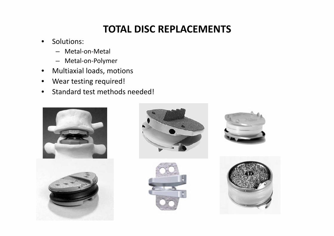
TOTAL DISC REPLACEMENTS• Solutions:
– Metal‐on‐Metal– Metal‐on‐Polymer
• Multiaxial loads, motions• Wear testing required!• Standard test methods needed!
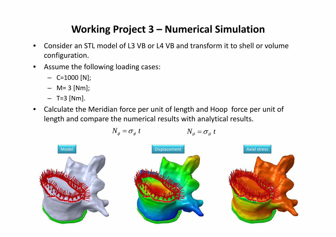
Working Project 3 – Numerical Simulation• Consider an STL model of L3 VB or L4 VB and transform it to shell or volume
configuration.• Assume the following loading cases:
– C=1000 [N];– M= 3 [Nm];– T=3 [Nm].
• Calculate the Meridian force per unit of length and Hoop force per unit of length and compare the numerical results with analytical results.
tN tN
Model Displacement Axial stress

HUMAN SPINAL INTERVERTEBRAL DISC• The inter‐vertebral disc (IVD) consists of:
– Annulus Fibrosus (AF): stress‐stiffening solid similar to a hyper‐elastic material.(increase in elastic modulus under loading). The annulus fibers are orientedhelically, at almost 30º–50º.
– Nucleus pulposus (NP).
• Biomechanical behaviour:– When the IVD is loaded in axial compression, the NP gets pressurized and
transmits radial stress to the AF, which in turn gets stressed.– As the IVD gets loaded, its deformation does not increase in the same
proportion as the loading.– The IVD sustains and transmits axial compression, bending, and torsional
loadings.– The IVD also functions as shock‐absorber component of the spinal unit.

HUMAN SPINAL INTERVERTEBRAL DISC• Geometry and deformation variables:
– The biomechanical behaviour is explained when the disc is loaded in axialcompression (or bending or torsion), the NP fluid gets pressurized and stressesthe surrounding annulus.
– The annulus under increased loadings, its elastic modulus increases, so thatthe deformations are contained. Example:
• E0 represents the residual Young’s modulus, equal to 4.2 [MPa];• is taken to be equal to the maximum value of the principal stress (which happens
to be the axial stress SZ).
– The internal pressure causes circumferential hoop tensile stress in theannulus. This stress in turn influences the strain state in the disc through itselastic modulus, and hence the axial and radial deformation.
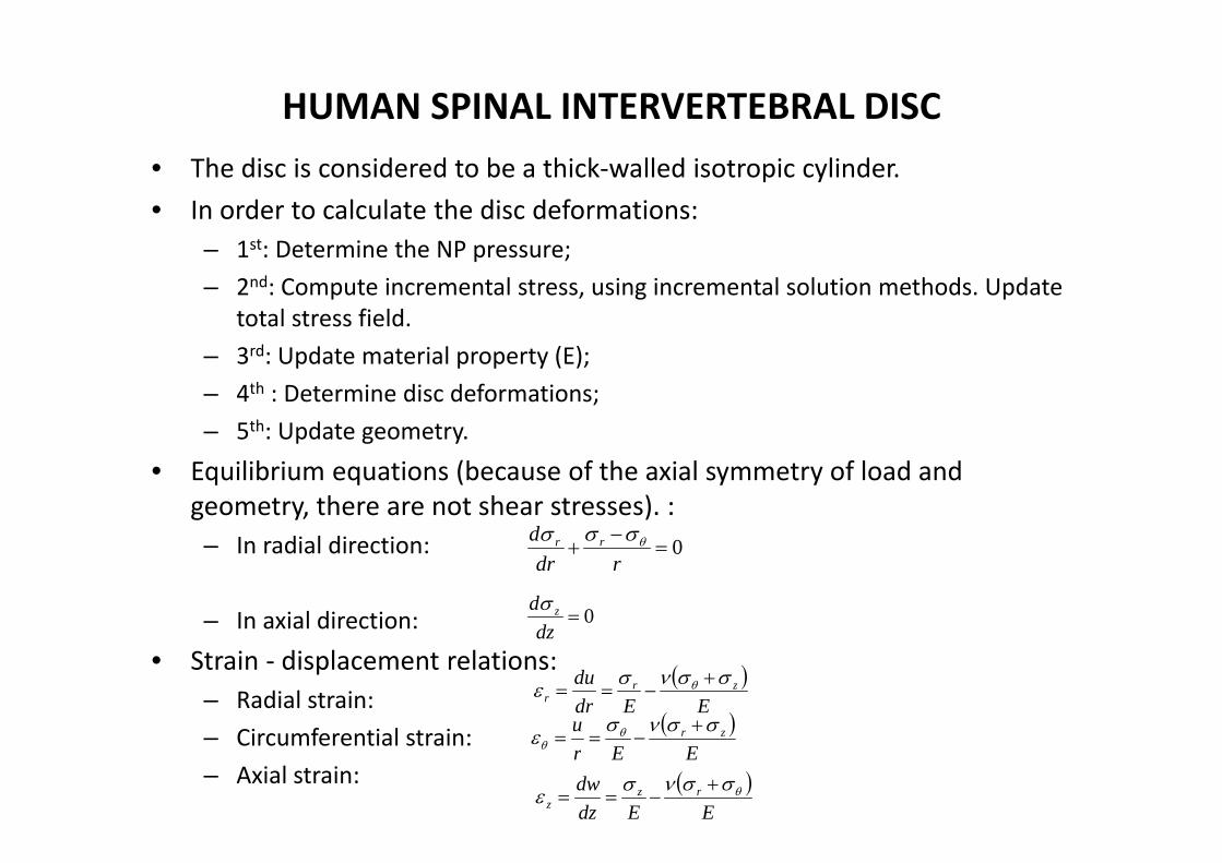
HUMAN SPINAL INTERVERTEBRAL DISC• The disc is considered to be a thick‐walled isotropic cylinder.• In order to calculate the disc deformations:
– 1st: Determine the NP pressure;– 2nd: Compute incremental stress, using incremental solution methods. Update
total stress field.– 3rd: Update material property (E);– 4th : Determine disc deformations;– 5th: Update geometry.
• Equilibrium equations (because of the axial symmetry of load and geometry, there are not shear stresses). :– In radial direction:
– In axial direction:
• Strain ‐ displacement relations: – Radial strain: – Circumferential strain:– Axial strain:
0
rdr
d rr
0dz
d z
EEdr
du zrr
EEr
u zr
EEdz
dw rzz

HUMAN SPINAL INTERVERTEBRAL DISC• Stress‐ displacement relations:
– Radial stress:
– Circumferential (hoop) stress:
– Axial stress:
• By direct substitution of the constitutive relations (top of slide) into the equilibrium equations:– Radial direction:
– Axial direction:
• Solutions for differential equations:– Radial displacement, dependent of A and B (constants of integrations):– Axial displacement, dependent of C and D (constants of integrations):
drdu
dzdw
ru
drduE
r
211
ru
dzdw
ru
drduE
211
dzdw
dzdw
ru
drduE
z
211
0121
ru
drdu
rdrdu
dzdw
ru
drdu
drd
021
dzdw
dzdw
ru
drdu
dzd
BrrAu
DCzw
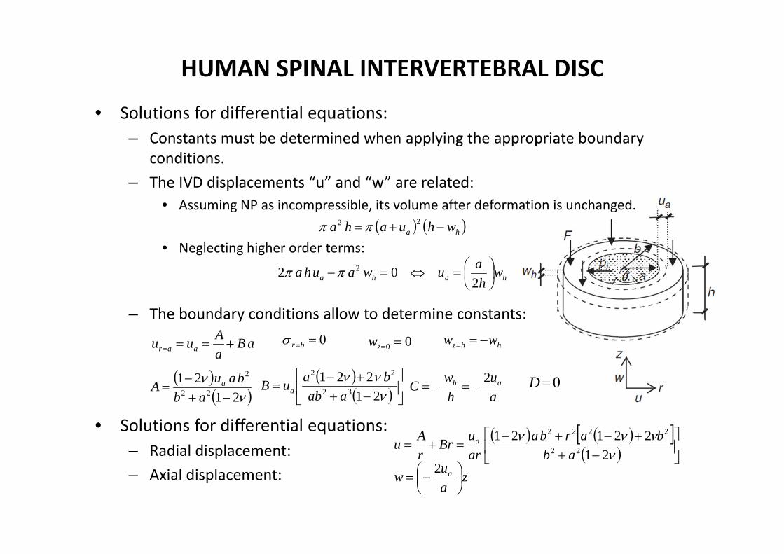
HUMAN SPINAL INTERVERTEBRAL DISC
• Solutions for differential equations:– Constants must be determined when applying the appropriate boundary
conditions.– The IVD displacements “u” and “w” are related:
• Assuming NP as incompressible, its volume after deformation is unchanged.
• Neglecting higher order terms:
– The boundary conditions allow to determine constants:
• Solutions for differential equations:– Radial displacement:– Axial displacement:
ha whuaha 22
haha whauwauha
202 2
aBaAuu aar
0br 00 zw hhz ww
21
2122
2
ab
bauA a 0Dau
hwC ah 2
21
22132
22
aabbauB a
2122121
22
2222
abbarba
aruBr
rAu a
zauw a
2
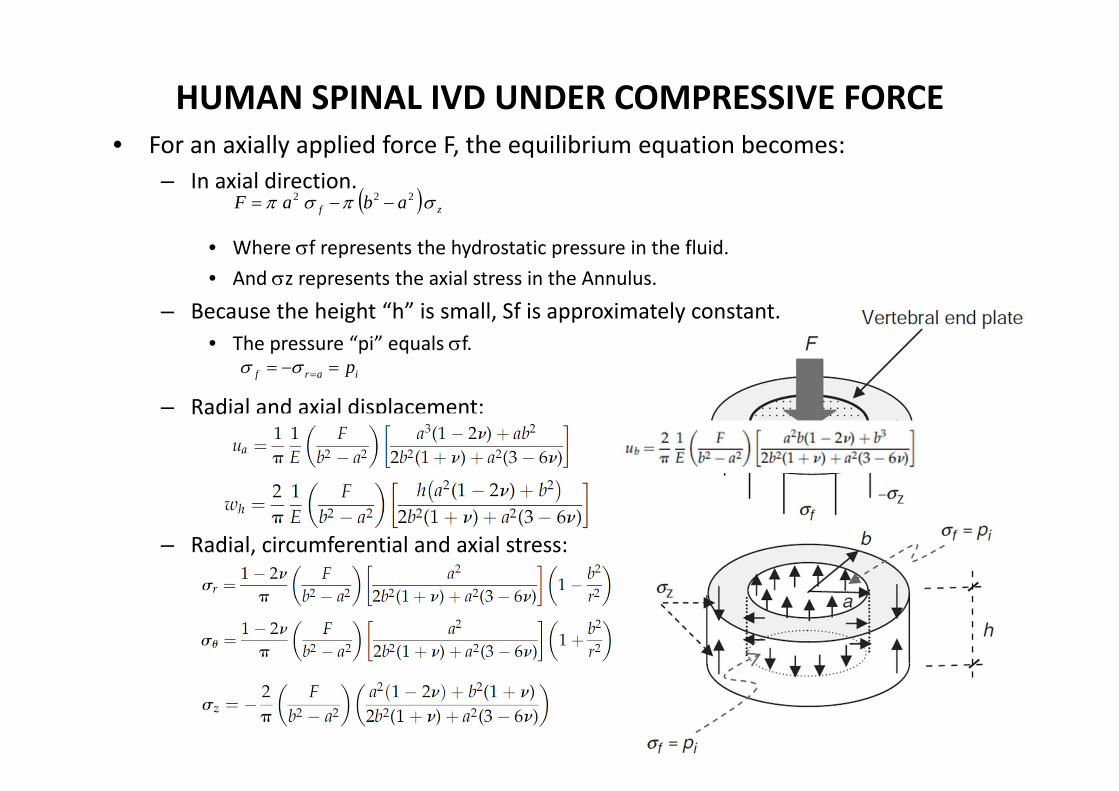
HUMAN SPINAL IVD UNDER COMPRESSIVE FORCE• For an axially applied force F, the equilibrium equation becomes:
– In axial direction.
• Where f represents the hydrostatic pressure in the fluid.• And z represents the axial stress in the Annulus.
– Because the height “h” is small, Sf is approximately constant.• The pressure “pi” equals f.
– Radial and axial displacement:
– Radial, circumferential and axial stress:
zf abaF 222
iarf p

HUMAN IVD UNDER COMPRESIVE FORCE• Non linear geometry solution algorithm (incremental load):
– Step 1: • Start from unloaded condition:• Material property:• Incremental force: • Incremental stresses are computed:• Determine the maximum value of these stresses to update material property:
• Calculate disc displacement, corresponding to incremental stress state:• Update disc geometry:
– Step 2:• Incremental force applied to the deformed geometry: • Incremental stresses are computed:• Determine the maximum value of these stresses to update material property:
• Calculate disc displacement, corresponding to incremental stress state:
• Update disc geometry:
– Step 3: Repeat step 2 until total compressive load reaches the specified value.
0z
0EE
NF 11
111 ,, zr
1z
473.011 3.3732.4 zE
111 ,, bah uuw
101101101 ,, bah ubbuaawhh
NF 12
222 ,, zr
2z
473.020
473.0212 3.3733.3732.4 zzz EE
212121 ,, bbaahh uuuuww
210221122112 ,, bbaahh uubbuuaawwhh

HUMAN IVD UNDER COMPRESSIVE FORCE
• Numercial results:
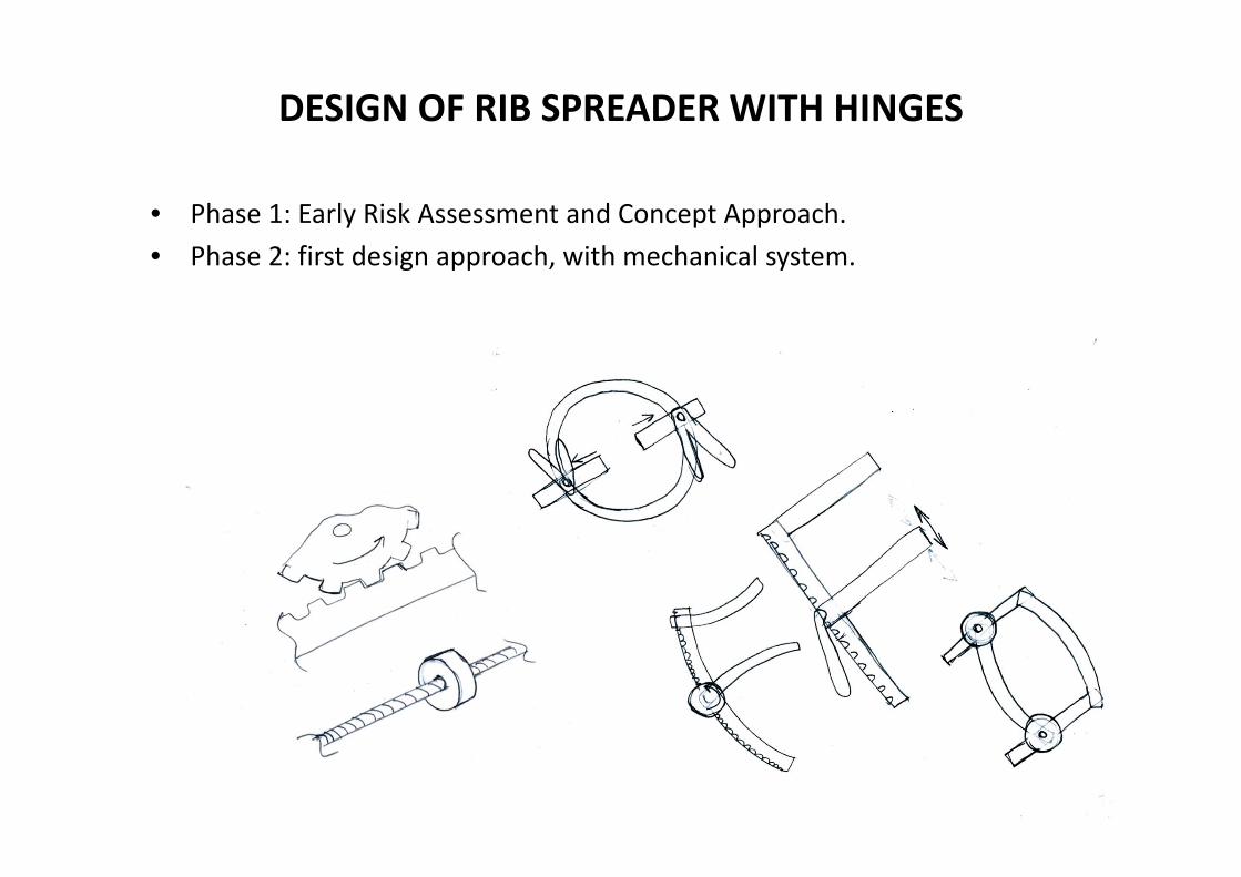
DESIGN OF RIB SPREADER WITH HINGES
• Phase 1: Early Risk Assessment and Concept Approach.• Phase 2: first design approach, with mechanical system.
Related Documents