USER’S MANUAL MODELS R88M-Ujjj15j/-Ujjj30j (AC Servo Motors) MODELS R88D-UTj (AC Servo Drivers) AC SERVO MOTORS/DRIVERS OMNUC U SERIES Cat. No. I514-E1-2

Welcome message from author
This document is posted to help you gain knowledge. Please leave a comment to let me know what you think about it! Share it to your friends and learn new things together.
Transcript

USER’S MANUAL
MODELS R88M-Ujjj15j/-Ujjj30j(AC Servo Motors)
MODELS R88D-UTj(AC Servo Drivers)
AC SERVO MOTORS/DRIVERS
OMNUC U SERIES
Cat. No. I514-E1-2

Thank you for choosing this OMNUC U-series product. Proper use and handlingof the product will ensure proper product performance, will length product life, andmay prevent possible accidents.Please read this manual thoroughly and handle and operate the product with care.
NOTICE1. This manual describes the functions of the product and relations with other prod-
ucts. You should assume that anything not described in this manual is not possible.2. Although care has been given in documenting the product, please contact your
OMRON representative if you have any suggestions on improving this manual.3. The product contains dangerous high voltages inside. Turn off the power and wait
for at least five minutes to allow power to discharge before handling or working withthe product. Never attempt to disassemble the product.
4. We recommend that you add the following precautions to any instruction manualsyou prepare for the system into which the product is being installed.S Precautions on the dangers of high-voltage equipment.S Precautions on touching the terminals of the product even after power has been
turned off. (These terminals are live even with the power turned off.)5. Specifications and functions may be changed without notice in order to improve
product performance.6. Positive and negative rotation of AC Servo Motors described in this manual are
defined as looking at the end of the output shaft of the motor as follows: counter-clockwise rotation is positive and clockwise rotation is negative.
7. Do not perform withstand-voltage or other megameter tests on the product. Doingso may damage internal components.
8. Servo Motors and Servo Drivers have a finite service life. Be sure to keep replace-ment products on hand and to consider the operating environment and other condi-tions affecting the service life.
9. The OMNUC UTj can control two groups of Servomotor models (i.e., 1,500-r/minand 3,000-r/min). Refer to the following for the descriptions of the 1,500-r/min and3,000-r/min models.S 1,500-r/min models: R88M-Ujjj15j-jS1, the rated number of revolutions
of which is 1,500 per minute.S 3,000-r/min models: R88M-Ujjj30j-j, the rated number of revolutions of
which is 3,000 per minute.Be sure to check the model that will be used before reading this manual.
Items to Check After UnpackingCheck the following items after removing the product from the package:S Has the correct product been delivered (i.e., the correct model number and speci-
fications)?S Has the product been damaged in shipping?S Are any screws or bolts loose?
!
!
!
Notice:OMRON products are manufactured for use according to proper procedures by a qualifiedoperator and only for the purposes described in this manual.
The following conventions are used to indicate and classify precautions in this manual.Always heed the information provided with them. Failure to heed precautions can result ininjury to people or damage to property.
DANGER Indicates an imminently hazardous situation which, if not avoided, will result in deathor serious injury.
WARNING Indicates a potentially hazardous situation which, if not avoided, could result in deathor serious injury.
Caution Indicates a potentially hazardous situation which, if not avoided, may result in minoror moderate injury, or property damage.
OMRON Product ReferencesAll OMRON products are capitalized in this manual. The word “Unit” is also capitalized whenit refers to an OMRON product, regardless of whether or not it appears in the proper nameof the product.
The abbreviation “Ch,” which appears in some displays and on some OMRON products,often means “word” and is abbreviated “Wd” in documentation in this sense.
The abbreviation “PC” means Programmable Controller and is not used as an abbreviationfor anything else.
Visual AidsThe following headings appear in the left column of the manual to help you locate differenttypes of information.
Note Indicates information of particular interest for efficient and convenient operation of the product.
OMRON, 1996All rights reserved. No part of this publication may be reproduced, stored in a retrieval sys-tem, or transmitted, in any form, or by any means, mechanical, electronic, photocopying,recording, or otherwise, without the prior written permission of OMRON.
No patent liability is assumed with respect to the use of the information contained herein.Moreover, because OMRON is constantly striving to improve its high-quality products, theinformation contained in this manual is subject to change without notice. Every precautionhas been taken in the preparation of this manual. Nevertheless, OMRON assumes noresponsibility for errors or omissions. Neither is any liability assumed for damages resultingfrom the use of the information contained in this publication.
!
!
!
!
!
!
!
!
!
!
General WarningsObserve the following warnings when using the OMNUC Servomotor and Servo Driver.
This manual may include illustrations of the product with protective covers removed in orderto describe the components of the product in detail. Make sure that these protective coversare on the product before use.
Consult your OMRON representative when using the product after a long period of storage.
WARNING Always connect the frame ground terminals of the Servo Driver and the Servomotorto a class-3 ground (to 100 Ω or less). Not connecting to a class-3 ground may resultin electric shock.
WARNING Do not touch the inside of the Servo Driver. Doing so may result in electric shock.
WARNING Do not remove the front cover, terminal covers, cables, Parameter Units, or optionalitems while the power is being supplied. Doing so may result in electric shock.
WARNING Installation, operation, maintenance, or inspection must be performed by authorizedpersonnel. Not doing so may result in electric shock or injury.
WARNING Wiring or inspection must be performed at least 5 minutes after turning off the powersupply. Doing so may result in electric shock.
WARNING Do not damage, press, or put excessive stress or heavy objects on the cables. Doingso may result in electric shock.
WARNING Do not touch the rotating parts of the Servomotor under operation. Doing so mayresult in injury.
WARNING Do not modify the product. Doing so may result in injury or damage to the product.
Caution Use the Servomotors and Servo Drivers in a specified combination. Doing so mayresult in fire or damage to the products.
Caution Do not store or install in the following places. Doing so may result in fire or damage tothe Product.
S Locations subject to direct sunlight.S Locations subject to temperatures or humidity outside the range specified in the
specifications.S Locations subject to condensation as the result of severe changes in temperature.S Locations subject to corrosive or flammable gases.S Locations subject to dust (especially iron dust) or salts.S Locations subject to shock or vibration.S Locations subject to exposure to water, oil, or chemicals.

!
!
!
!
!
!
!
!
!
!
!
!
!
Caution Do not touch the Servo Driver radiator or Servomotor while the power is being sup-plied or soon after the power is turned off. Doing so may result in a skin burn due tothe hot surface.
Storage and Transportation PrecautionsCaution Do not hold by the cables or motor shaft while transporting the product. Doing so
may result in injury or malfunction.
Caution Do not place any load exceeding the figure indicated on the product. Doing so mayresult in injury or malfunction.
Caution Use the motor eye-bolts only for transporting the Motor. Using them for transportingthe machinery may result in injury or malfunction.
Installation and Wiring PrecautionsCaution Do not step on or place a heavy object on the product. Doing so may result in injury.
Caution Do not cover the inlet or outlet ports and prevent any foreign objects from enteringthe product. Doing so may result in fire.
Caution Be sure to install the product in the correct direction. Not doing so may result in mal-function.
Caution Provide the specified clearances between the Servo Driver and the control panel orwith other devices. Not doing so may result in fire or malfunction.
Caution Do not apply any strong impact. Doing so may result in malfunction.
Caution Be sure to wire correctly and securely. Not doing so may result in motor runaway,injury, or malfunction.
Caution Be sure that all the mounting screws, terminal screws, and cable connector screwsare tightened to the torque specified in the relevant manuals. Incorrect tighteningtorque may result in malfunction.
Caution Use crimp terminals for wiring. Do not connect bare stranded wires directly to termi-nals. Connection of bare stranded wires may result in burning.
Caution Always use the power supply voltage specified in the User’s Manual. An incorrectvoltage may result in malfunction or burning.
!
!
!
!
!
!
!
!
!
!
!
Caution Take appropriate measures to ensure that the specified power with the rated voltageand frequency is supplied. Be particularly careful in places where the power supplyis unstable. An incorrect power supply may result in malfunction.
Caution Install external breakers and take other safety measures against short-circuiting inexternal wiring. Insufficient safety measures against short-circuiting may result inburning.
Caution Provide an appropriate stopping device on the machine side to secure safety. (Aholding brake is not a stopping device for securing safety.) Not doing so may result ininjury.
Caution Provide an external emergency stopping device that allows an instantaneous stop ofoperation and power interruption. Not doing so may result in injury.
Caution Take appropriate and sufficient countermeasures when installing systems in the fol-lowing locations:
S Locations subject to static electricity or other forms of noise.S Locations subject to strong electromagnetic fields and magnetic fields.S Locations subject to possible exposure to radioactivity.S Locations close to power supplies.
Operation and Adjustment PrecautionsCaution Check the newly set parameters for proper execution before actually running them.
Not doing so may result in equipment damage.
Caution Do not make any extreme adjustments or setting changes. Doing so may result inunstable operation and injury.
Caution Separate the Servomotor from the machine, check for proper operation, and thenconnect to the machine. Not doing so may cause injury.
Caution When an alarm occurs, remove the cause, reset the alarm after confirming safety,and then resume operation. Not doing so may result in injury.
Caution Do not come close to the machine immediately after resetting momentary powerinterruption to avoid an unexpected restart. (Take appropriate measures to securesafety against an unexpected restart.) Doing so may result in injury.
Caution Do not use the built-in brake of the Servomotor for ordinary braking. Doing so mayresult in malfunction.

!
!
Maintenance and Inspection PrecautionsWARNING Do not attempt to disassemble, repair, or modify any Units. Any attempt to do so may
result in malfunction, fire, or electric shock.
Caution Resume operation only after transferring to the new Unit the contents of the datarequired for operation. Not doing so may result in an unexpected operation.

Warning LabelsWarning labels are pasted on the product as shown in the following illustration. Be sure tofollow the instructions given there.
Warning labels
Warning Labels for Non-conforming Models
Warning label 1
Warning label 2
Warning Labels for Models Conforming to EC Directives
Warning label 1
Warning label 2

VISUAL INDEX
For users who wish to operate as quickly as possible.
- The following portions of this manual provide the minimum information required for operation.Be sure you fully understand at least the information in these portions before attempting opera-tion.Chapter 2 System Design and Installation, and sections 3-1, 3-2, 3-3, and 3-4 of Chapter 3Operation.Instructions for jog operation using a Parameter Unit are provided in 3-4.
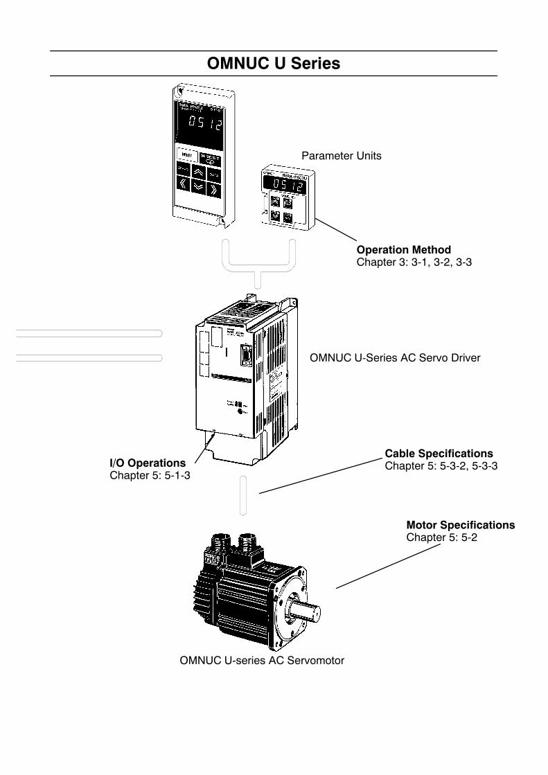
OMNUC U is a series of fullydigital AC servo drivers builton advanced OMRON soft-ware servo technology. It pro-vides high performance, asensitive man-machine inter-face, and economy.
Controller Connecting CableChapter 5: 5-3-1
Setting Functions
- Using Parameter Unit: Chapter 3, section 3-1-3- Setting, checking setup parameters: Chapter 3, section 3-3-1- Important setup parameters: Chapter 3, section 3-3-1- Setting, checking user parameters Chapter 3, section 3-3-2- Important user parameters Chapter 3, section 3-3-3
Adjustments and Troubleshooting
-Making adjustments: Chapter 3, section 3-5- Using displays: Chapter 4, section 4-2- Using monitor outputs: Chapter 4, section 4-3- Protections and diagnostic functions:Chapter 4, section 4-4
Analog input
Pulse train input
SYSMAC C/CVProgrammable Controller Position Control Unit
C500-NC222-EMotion Control UnitsCV500-MC221/421C200H-MC221
SYSMAC C/CVProgrammable Controller
Position Control Units3G2A5-NC111-EV1C500-NC211
SYSMAC C200HX/HG/HEProgrammable Controller
Position Control UnitsC200H-NC112C200H-NC211C200HW-NC113C200HW-NC213C200HW-NC413
OMNUC U Series
OMNUC U-Series AC Servo Driver
I/O OperationsChapter 5: 5-1-3
Cable SpecificationsChapter 5: 5-3-2, 5-3-3
Motor SpecificationsChapter 5: 5-2
OMNUC U-series AC Servomotor
Operation MethodChapter 3: 3-1, 3-2, 3-3
Parameter Units

Table of Contents
Chapter 1. Introduction 1-1. . . . . . . . . . . . . . . . . . . . . . . . . . . . . . . . . . . . .1-1 Features 1-2. . . . . . . . . . . . . . . . . . . . . . . . . . . . . . . . . . . . . . . . . . . . . . . . . . . . . . . . . . . . . . . . . . .1-2 System Configuration 1-7. . . . . . . . . . . . . . . . . . . . . . . . . . . . . . . . . . . . . . . . . . . . . . . . . . . . . . . .1-3 Servo Driver Nomenclature 1-8. . . . . . . . . . . . . . . . . . . . . . . . . . . . . . . . . . . . . . . . . . . . . . . . . . . .1-4 Applicable Standards and Models 1-9. . . . . . . . . . . . . . . . . . . . . . . . . . . . . . . . . . . . . . . . . . . . . . .
Chapter 2. System Design and Installation 2-1. . . . . . . . . . . . . . . . . . . . . .2-1 Installation 2-2. . . . . . . . . . . . . . . . . . . . . . . . . . . . . . . . . . . . . . . . . . . . . . . . . . . . . . . . . . . . . . . . .
2-1-1 External Dimensions (Unit: mm) 2-2. . . . . . . . . . . . . . . . . . . . . . . . . . . . . . . . . . . . . . . . .2-1-2 Installation Conditions 2-17. . . . . . . . . . . . . . . . . . . . . . . . . . . . . . . . . . . . . . . . . . . . . . . . .
2-2 Wiring and Connections (Models Not Conforming to Standards) 2-24. . . . . . . . . . . . . . . . . . . . . .2-2-1 Connecting OMRON Servo Controllers 2-24. . . . . . . . . . . . . . . . . . . . . . . . . . . . . . . . . . . .2-2-2 Wiring Servo Drivers 2-26. . . . . . . . . . . . . . . . . . . . . . . . . . . . . . . . . . . . . . . . . . . . . . . . . .2-2-3 Wiring for Noise Resistance 2-30. . . . . . . . . . . . . . . . . . . . . . . . . . . . . . . . . . . . . . . . . . . . .2-2-4 Peripheral Device Connection Examples 2-37. . . . . . . . . . . . . . . . . . . . . . . . . . . . . . . . . . .
2-3 Wiring and Connections (Models Conforming to EC Directives) 2-38. . . . . . . . . . . . . . . . . . . . . .2-3-1 Connecting OMRON Servo Controllers 2-38. . . . . . . . . . . . . . . . . . . . . . . . . . . . . . . . . . . .2-3-2 Wiring Servo Drivers 2-40. . . . . . . . . . . . . . . . . . . . . . . . . . . . . . . . . . . . . . . . . . . . . . . . . .2-3-3 Wiring Conditions Satisfying EMC Directives 2-43. . . . . . . . . . . . . . . . . . . . . . . . . . . . . .2-3-4 Peripheral Device Connection Examples 2-52. . . . . . . . . . . . . . . . . . . . . . . . . . . . . . . . . . .
Chapter 3. Operation 3-1. . . . . . . . . . . . . . . . . . . . . . . . . . . . . . . . . . . . . . .3-1 Beginning Operation 3-3. . . . . . . . . . . . . . . . . . . . . . . . . . . . . . . . . . . . . . . . . . . . . . . . . . . . . . . . .
3-1-1 Operational Procedure 3-3. . . . . . . . . . . . . . . . . . . . . . . . . . . . . . . . . . . . . . . . . . . . . . . . .3-1-2 Turning On Power and Checking Displays 3-4. . . . . . . . . . . . . . . . . . . . . . . . . . . . . . . . .3-1-3 Using Parameter Units 3-6. . . . . . . . . . . . . . . . . . . . . . . . . . . . . . . . . . . . . . . . . . . . . . . . .
3-2 System Check Mode (Cn-00) 3-9. . . . . . . . . . . . . . . . . . . . . . . . . . . . . . . . . . . . . . . . . . . . . . . . . .3-3 Function Settings 3-10. . . . . . . . . . . . . . . . . . . . . . . . . . . . . . . . . . . . . . . . . . . . . . . . . . . . . . . . . . . .
3-3-1 Setting and Checking Setup Parameters (Cn-01, 02) 3-10. . . . . . . . . . . . . . . . . . . . . . . . . .3-3-2 Setting and Checking User Parameters (Cn-03 to 2d) 3-14. . . . . . . . . . . . . . . . . . . . . . . . .3-3-3 Important User Parameters 3-20. . . . . . . . . . . . . . . . . . . . . . . . . . . . . . . . . . . . . . . . . . . . . .3-3-4 Setting Internal Speed Control 3-21. . . . . . . . . . . . . . . . . . . . . . . . . . . . . . . . . . . . . . . . . . .3-3-5 Switching Control Mode 3-26. . . . . . . . . . . . . . . . . . . . . . . . . . . . . . . . . . . . . . . . . . . . . . . .3-3-6 Soft Start Function 3-28. . . . . . . . . . . . . . . . . . . . . . . . . . . . . . . . . . . . . . . . . . . . . . . . . . . .3-3-7 Electronic Gear Function (Position Control) 3-30. . . . . . . . . . . . . . . . . . . . . . . . . . . . . . . .3-3-8 Encoder Dividing Function 3-31. . . . . . . . . . . . . . . . . . . . . . . . . . . . . . . . . . . . . . . . . . . . . .3-3-9 Bias Function (Position Control) 3-32. . . . . . . . . . . . . . . . . . . . . . . . . . . . . . . . . . . . . . . . .3-3-10 Torque Limit Function (Position Control, Speed Control, Torque Control) 3-33. . . . . . . .3-3-11 Speed Limit Function (Torque Control) 3-35. . . . . . . . . . . . . . . . . . . . . . . . . . . . . . . . . . . .3-3-12 Torque Feed-forward Function (Speed Control) 3-36. . . . . . . . . . . . . . . . . . . . . . . . . . . . .3-3-13 Brake Interlock (for Motors With Brakes) 3-37. . . . . . . . . . . . . . . . . . . . . . . . . . . . . . . . . .
3-4 Trial Operation 3-40. . . . . . . . . . . . . . . . . . . . . . . . . . . . . . . . . . . . . . . . . . . . . . . . . . . . . . . . . . . . . .3-5 Making Adjustments 3-42. . . . . . . . . . . . . . . . . . . . . . . . . . . . . . . . . . . . . . . . . . . . . . . . . . . . . . . . .
3-5-1 Auto-tuning 3-42. . . . . . . . . . . . . . . . . . . . . . . . . . . . . . . . . . . . . . . . . . . . . . . . . . . . . . . . . .3-5-2 Manually Adjusting Gain 3-44. . . . . . . . . . . . . . . . . . . . . . . . . . . . . . . . . . . . . . . . . . . . . . .3-5-3 Adjusting Command Offset 3-51. . . . . . . . . . . . . . . . . . . . . . . . . . . . . . . . . . . . . . . . . . . . .
3-6 Regenerative Energy Absorption 3-53. . . . . . . . . . . . . . . . . . . . . . . . . . . . . . . . . . . . . . . . . . . . . . . .3-6-1 Calculating Regenerative Energy 3-53. . . . . . . . . . . . . . . . . . . . . . . . . . . . . . . . . . . . . . . . .3-6-2 Servo Driver Absorbable Regenerative Energy 3-55. . . . . . . . . . . . . . . . . . . . . . . . . . . . . .3-6-3 Absorption of Regenerative Energy by Servo Drivers
with External Regenerative Resistors 3-56. . . . . . . . . . . . . . . . . . . . . . . . . . . . . . . . . . . . . .
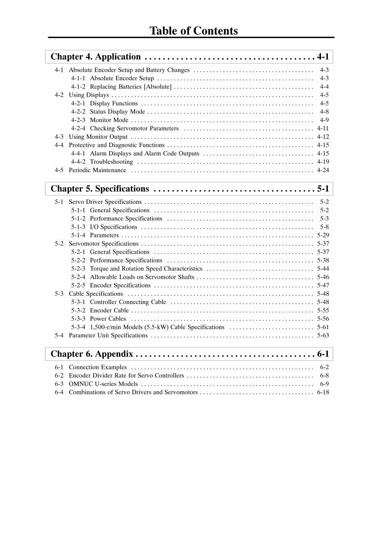
Table of Contents
ii
Chapter 4. Application 4-1. . . . . . . . . . . . . . . . . . . . . . . . . . . . . . . . . . . . . .4-1 Absolute Encoder Setup and Battery Changes 4-3. . . . . . . . . . . . . . . . . . . . . . . . . . . . . . . . . . . . .
4-1-1 Absolute Encoder Setup 4-3. . . . . . . . . . . . . . . . . . . . . . . . . . . . . . . . . . . . . . . . . . . . . . . .4-1-2 Replacing Batteries [Absolute] 4-4. . . . . . . . . . . . . . . . . . . . . . . . . . . . . . . . . . . . . . . . . . .
4-2 Using Displays 4-5. . . . . . . . . . . . . . . . . . . . . . . . . . . . . . . . . . . . . . . . . . . . . . . . . . . . . . . . . . . . . .4-2-1 Display Functions 4-5. . . . . . . . . . . . . . . . . . . . . . . . . . . . . . . . . . . . . . . . . . . . . . . . . . . . .4-2-2 Status Display Mode 4-8. . . . . . . . . . . . . . . . . . . . . . . . . . . . . . . . . . . . . . . . . . . . . . . . . . .4-2-3 Monitor Mode 4-9. . . . . . . . . . . . . . . . . . . . . . . . . . . . . . . . . . . . . . . . . . . . . . . . . . . . . . . .4-2-4 Checking Servomotor Parameters 4-11. . . . . . . . . . . . . . . . . . . . . . . . . . . . . . . . . . . . . . . .
4-3 Using Monitor Output 4-12. . . . . . . . . . . . . . . . . . . . . . . . . . . . . . . . . . . . . . . . . . . . . . . . . . . . . . . .4-4 Protective and Diagnostic Functions 4-15. . . . . . . . . . . . . . . . . . . . . . . . . . . . . . . . . . . . . . . . . . . . .
4-4-1 Alarm Displays and Alarm Code Outputs 4-15. . . . . . . . . . . . . . . . . . . . . . . . . . . . . . . . . .4-4-2 Troubleshooting 4-19. . . . . . . . . . . . . . . . . . . . . . . . . . . . . . . . . . . . . . . . . . . . . . . . . . . . . .
4-5 Periodic Maintenance 4-24. . . . . . . . . . . . . . . . . . . . . . . . . . . . . . . . . . . . . . . . . . . . . . . . . . . . . . . .
Chapter 5. Specifications 5-1. . . . . . . . . . . . . . . . . . . . . . . . . . . . . . . . . . . .5-1 Servo Driver Specifications 5-2. . . . . . . . . . . . . . . . . . . . . . . . . . . . . . . . . . . . . . . . . . . . . . . . . . . .
5-1-1 General Specifications 5-2. . . . . . . . . . . . . . . . . . . . . . . . . . . . . . . . . . . . . . . . . . . . . . . . .5-1-2 Performance Specifications 5-3. . . . . . . . . . . . . . . . . . . . . . . . . . . . . . . . . . . . . . . . . . . . .5-1-3 I/O Specifications 5-8. . . . . . . . . . . . . . . . . . . . . . . . . . . . . . . . . . . . . . . . . . . . . . . . . . . . .5-1-4 Parameters 5-29. . . . . . . . . . . . . . . . . . . . . . . . . . . . . . . . . . . . . . . . . . . . . . . . . . . . . . . . . . .
5-2 Servomotor Specifications 5-37. . . . . . . . . . . . . . . . . . . . . . . . . . . . . . . . . . . . . . . . . . . . . . . . . . . . .5-2-1 General Specifications 5-37. . . . . . . . . . . . . . . . . . . . . . . . . . . . . . . . . . . . . . . . . . . . . . . . .5-2-2 Performance Specifications 5-38. . . . . . . . . . . . . . . . . . . . . . . . . . . . . . . . . . . . . . . . . . . . .5-2-3 Torque and Rotation Speed Characteristics 5-44. . . . . . . . . . . . . . . . . . . . . . . . . . . . . . . . .5-2-4 Allowable Loads on Servomotor Shafts 5-46. . . . . . . . . . . . . . . . . . . . . . . . . . . . . . . . . . . .5-2-5 Encoder Specifications 5-47. . . . . . . . . . . . . . . . . . . . . . . . . . . . . . . . . . . . . . . . . . . . . . . . .
5-3 Cable Specifications 5-48. . . . . . . . . . . . . . . . . . . . . . . . . . . . . . . . . . . . . . . . . . . . . . . . . . . . . . . . .5-3-1 Controller Connecting Cable 5-48. . . . . . . . . . . . . . . . . . . . . . . . . . . . . . . . . . . . . . . . . . . .5-3-2 Encoder Cable 5-55. . . . . . . . . . . . . . . . . . . . . . . . . . . . . . . . . . . . . . . . . . . . . . . . . . . . . . . .5-3-3 Power Cables 5-56. . . . . . . . . . . . . . . . . . . . . . . . . . . . . . . . . . . . . . . . . . . . . . . . . . . . . . . .5-3-4 1,500-r/min Models (5.5-kW) Cable Specifications 5-61. . . . . . . . . . . . . . . . . . . . . . . . . .
5-4 Parameter Unit Specifications 5-63. . . . . . . . . . . . . . . . . . . . . . . . . . . . . . . . . . . . . . . . . . . . . . . . . .
Chapter 6. Appendix 6-1. . . . . . . . . . . . . . . . . . . . . . . . . . . . . . . . . . . . . . . .6-1 Connection Examples 6-2. . . . . . . . . . . . . . . . . . . . . . . . . . . . . . . . . . . . . . . . . . . . . . . . . . . . . . . .6-2 Encoder Divider Rate for Servo Controllers 6-8. . . . . . . . . . . . . . . . . . . . . . . . . . . . . . . . . . . . . . .6-3 OMNUC U-series Models 6-9. . . . . . . . . . . . . . . . . . . . . . . . . . . . . . . . . . . . . . . . . . . . . . . . . . . . .6-4 Combinations of Servo Drivers and Servomotors 6-18. . . . . . . . . . . . . . . . . . . . . . . . . . . . . . . . . . .

Chapter 1
Introduction1-1 Features
1-2 Servo Driver Nomenclature1-3 Applicable Standards and Models
1
1-2
1-2
1-1 Features
With their superior performance and fast response times, and an output capacity of up to 5 kW, these ACServomotors and Servo Drivers have improved features of previous models.
H Models Bearing the CE Marking and Complying with EC DirectivesServo Driver and Servomotor models satisfying the LVD (Low-voltage Directives) and EMC (electro-magnetic compatibility) requirements of EC Directives are available. These models are the same as theU-series models in performance and function and help a customer’s products equipped with these mod-els satisfy EC Directives with ease.
H Servo Driver Requiring External Regenerative ResistorsServomotor models connecting to external regenerative resistors and complying with EC Directives areavailable.These Servomotor models are available to vertical shaft applications and other applications that gener-ate high regenerative energy.For detailed information of external regenerative resistors, refer to 3-6 Regenerative Energy Absorp-tion.
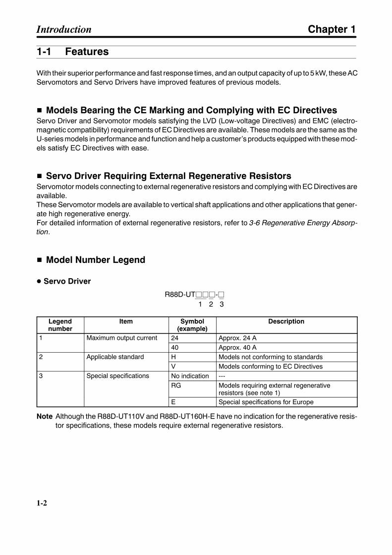
H Model Number Legend
D Servo Driver
R88D-UTjjj-j1 2 3
Legendnumber
Item Symbol(example)
Description
1 Maximum output current 24 Approx. 24 A1 Maximum output current40 Approx. 40 A
2 Applicable standard H Models not conforming to standards2 Applicable standardV Models conforming to EC Directives
3 Special specifications No indication ---3 Special specificationsRG Models requiring external regenerative
resistors (see note 1)E Special specifications for Europe
Note Although the R88D-UT110V and R88D-UT160H-E have no indication for the regenerative resis-tor specifications, these models require external regenerative resistors.
Introduction Chapter 1
1-3
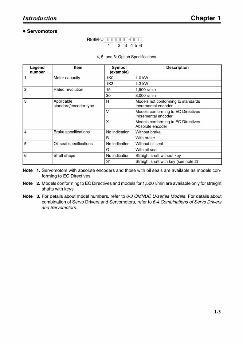
D Servomotors
R88M-Ujjjjjj-jjj1 2 3 4 5 6
4, 5, and 6: Option Specifications
Legendnumber
Item Symbol(example)
Description
1 Motor capacity 1K0 1.0 kW1 Motor capacity1K3 1.3 kW
2 Rated revolution 15 1,500 r/min2 Rated revolution30 3,000 r/min
3 Applicablestandard/encoder type
H Models not conforming to standardsIncremental encoderstandard/encoder type
V Models conforming to EC DirectivesIncremental encoder
X Models conforming to EC DirectivesAbsolute encoder
4 Brake specifications No indication Without brake4 Brake specificationsB With brake
5 Oil seal specifications No indication Without oil seal5 Oil seal specificationsO With oil seal
6 Shaft shape No indication Straight shaft without key6 Shaft shapeS1 Straight shaft with key (see note 2)
Note 1. Servomotors with absolute encoders and those with oil seals are available as models con-forming to EC Directives.
Note 2. Models conforming to EC Directives and models for 1,500 r/min are available only for straightshafts with keys.
Note 3. For details about model numbers, refer to 6-3 OMNUC U-series Models. For details aboutcombination of Servo Drivers and Servomotors, refer to 6-4 Combinations of Servo Driversand Servomotors.
Introduction Chapter 1
1-4
1-4
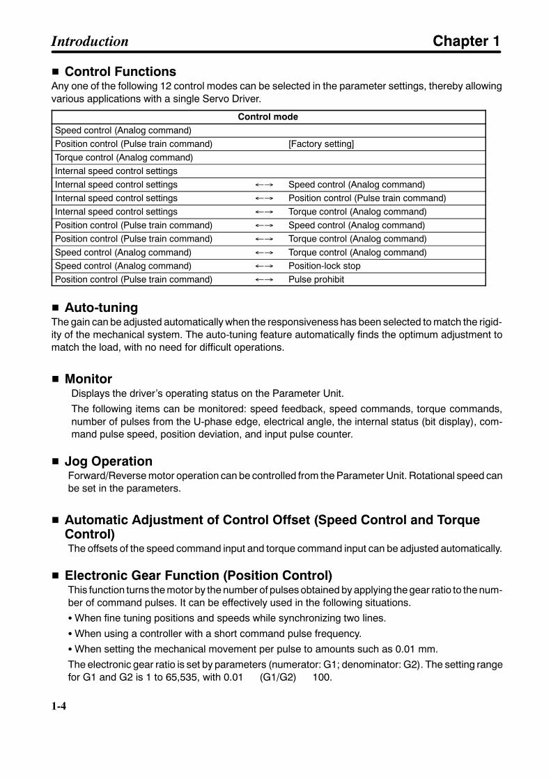
H Control FunctionsAny one of the following 12 control modes can be selected in the parameter settings, thereby allowingvarious applications with a single Servo Driver.
Control modeSpeed control (Analog command)Position control (Pulse train command) [Factory setting]Torque control (Analog command)Internal speed control settingsInternal speed control settings ←→ Speed control (Analog command)Internal speed control settings ←→ Position control (Pulse train command)Internal speed control settings ←→ Torque control (Analog command)Position control (Pulse train command) ←→ Speed control (Analog command)Position control (Pulse train command) ←→ Torque control (Analog command)Speed control (Analog command) ←→ Torque control (Analog command)Speed control (Analog command) ←→ Position-lock stopPosition control (Pulse train command) ←→ Pulse prohibit
H Auto-tuningThe gain can be adjusted automatically when the responsiveness has been selected to match the rigid-ity of the mechanical system. The auto-tuning feature automatically finds the optimum adjustment tomatch the load, with no need for difficult operations.
H MonitorDisplays the driver’s operating status on the Parameter Unit.The following items can be monitored: speed feedback, speed commands, torque commands,number of pulses from the U-phase edge, electrical angle, the internal status (bit display), com-mand pulse speed, position deviation, and input pulse counter.
H Jog OperationForward/Reverse motor operation can be controlled from the Parameter Unit. Rotational speed canbe set in the parameters.
H Automatic Adjustment of Control Offset (Speed Control and TorqueControl)The offsets of the speed command input and torque command input can be adjusted automatically.
H Electronic Gear Function (Position Control)This function turns the motor by the number of pulses obtained by applying the gear ratio to the num-ber of command pulses. It can be effectively used in the following situations.SWhen fine tuning positions and speeds while synchronizing two lines.
SWhen using a controller with a short command pulse frequency.SWhen setting the mechanical movement per pulse to amounts such as 0.01 mm.The electronic gear ratio is set by parameters (numerator: G1; denominator: G2). The setting rangefor G1 and G2 is 1 to 65,535, with 0.01 (G1/G2) 100.
Introduction Chapter 1
1-5
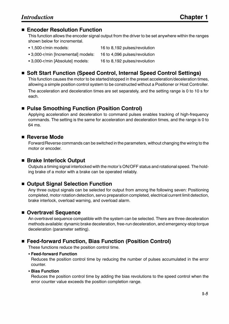
H Encoder Resolution FunctionThis function allows the encoder signal output from the driver to be set anywhere within the rangesshown below for incremental.
S 1,500-r/min models: 16 to 8,192 pulses/revolution
S 3,000-r/min [Incremental] models: 16 to 4,096 pulses/revolution
S 3,000-r/min [Absolute] models: 16 to 8,192 pulses/revolution
H Soft Start Function (Speed Control, Internal Speed Control Settings)This function causes the motor to be started/stopped in the preset acceleration/deceleration times,allowing a simple position control system to be constructed without a Positioner or Host Controller.
The acceleration and deceleration times are set separately, and the setting range is 0 to 10 s foreach.
H Pulse Smoothing Function (Position Control)Applying acceleration and deceleration to command pulses enables tracking of high-frequencycommands. The setting is the same for acceleration and deceleration times, and the range is 0 to64 ms.
H Reverse ModeForward/Reverse commands can be switched in the parameters, without changing the wiring to themotor or encoder.
H Brake Interlock OutputOutputs a timing signal interlocked with the motor’s ON/OFF status and rotational speed. The hold-ing brake of a motor with a brake can be operated reliably.
H Output Signal Selection FunctionAny three output signals can be selected for output from among the following seven: Positioningcompleted, motor rotation detection, servo preparation completed, electrical current limit detection,brake interlock, overload warning, and overload alarm.
H Overtravel SequenceAn overtravel sequence compatible with the system can be selected. There are three decelerationmethods available: dynamic brake deceleration, free-run deceleration, and emergency-stop torquedeceleration (parameter setting).
H Feed-forward Function, Bias Function (Position Control)These functions reduce the position control time.
S Feed-forward FunctionReduces the position control time by reducing the number of pulses accumulated in the errorcounter.
S Bias FunctionReduces the position control time by adding the bias revolutions to the speed control when theerror counter value exceeds the position completion range.
Introduction Chapter 1

1-6
1-6
H Personal Computer MonitorThe special Servo Driver Communications Software allows parameter setting, speed and currentmonitoring, I/O monitoring, auto-tuning, and jog operations to be performed from a personal com-puter. It is also possible to perform multiple-axis communications that set the parameters and moni-tor operation of several drivers.
Introduction Chapter 1
1-7
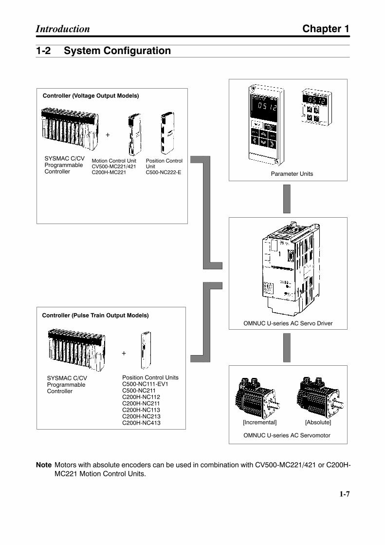
1-2 System Configuration
SYSMAC C/CVProgrammableController
+
+
Position Control UnitsC500-NC111-EV1C500-NC211C200H-NC112C200H-NC211C200H-NC113C200H-NC213C200H-NC413
Motion Control UnitCV500-MC221/421C200H-MC221
Position ControlUnitC500-NC222-E
Controller (Voltage Output Models)
Controller (Pulse Train Output Models)
Parameter Units
OMNUC U-series AC Servo Driver
OMNUC U-series AC Servomotor
SYSMAC C/CVProgrammableController
[Incremental] [Absolute]
Note Motors with absolute encoders can be used in combination with CV500-MC221/421 or C200H-MC221 Motion Control Units.
Introduction Chapter 1

1-8
1-8
1-3 Servo Driver Nomenclature
H Front View
Terminal block
CN4: Connector formonitor output
Power supplyindicator
CN1: Control I/Oconnector
CN2: Encoder connector
SW1: Unit No. setting switch(when personal computermonitor is used)
Charge indicator
Alarm indicator
CN3: ParameterUnit connector
R88D-UT40H
Introduction Chapter 1

1-9
1-4 Applicable Standards and Models
H Applicable StandardsEC
DirectivesProduct Applicable standard Remarks
Low voltage AC Servo Driver EN61010-1 Safety requirements for electricalequipment for measurement, control, andlaboratory use.
AC Servo Motor IEC34-1, -5, -8, -9 Rotating electrical machines.EMC AC Servo Driver
and AC ServomotorEN55011 class Agroup 1
Limits and methods of measurement ofradio disturbance characteristics ofindustrial, scientific, and medical (ISM)radio-frequency equipment.
EN50082-2 Electromagnetic compatibility genericimmunity standard, Part 2 Industrialenvironment.
Note Installation under the conditions specified in 2-3-3 Wiring Conditions Satisfying EMC Directives isrequired to conform to EMC Directives.
H Applicable ModelsSupply voltage Output AC Servo Driver AC ServomotorSupply voltage Output AC Servo Driver
IncrementalEncoder
Absolute Encoder
200 VAC 1 kW R88D-UT24VR88D-UT24V-RG
R88M-U1K030V-jS1 R88M-U1K030X-jS1
1.3 kW R88D-UT40VR88D-UT40V-RG
R88M-U1K315V-jS1 R88M-U1K315X-jS1
1.5 kWR88D-UT40VR88D-UT40V-RG R88M-U1K530V-jS1 R88M-U1K530X-jS1
1.8 kW R88D-UT60VR88D-UT60V-RG
R88M-U1K815V-jS1 R88M-U1K815X-jS1
2 kWR88D-UT60VR88D-UT60V-RG R88M-U2K030V-jS1 R88M-U2K030X-jS1
2.9 kW R88D-UT80VR88D-UT80V-RG
R88M-U2K915V-jS1 R88M-U2K915X-jS1
3 kWR88D-UT80VR88D-UT80V-RG R88M-U3K030V-jS1 R88M-U3K030X-jS1
4 kW R88D-UT110V R88M-U4K030V-jS1 R88M-U4K030X-jS1
4.4 kWR88D-UT110V
R88M-U4K415V-jS1 R88M-U4K415X-jS1
5.0 kW R88M-U5K030V-jS1 R88M-U5K030X-jS1
5.5 kW R88D-UT160V-E R88M-U5K515V-jS1 R88M-U5K515X-jS1
Introduction Chapter 1

Chapter 2
System Design and Installation
2-1 Installation
2-2 Wiring and Connections(Models Not Conforming to Standards)
2-3 Wiring and Connections(Models Conforming to EC Directives)
2

2-2
2-2
2-1 Installation2-1-1 External Dimensions (Unit: mm)H AC Servo DriversD R88D-UT40H-E
R88D-UT24V/-UT40VR88D-UT24V-RG/-UT40V-RG
Two, 5.5 dia.
110
92
5.5 35 125 65
235
250
189.
560
.5
D R88D-UT60H-E/-UT80H-ER88D-UT60V/-UT80VR88D-UT60V-RG/-UT80V-RG
Two, 5.5 dia.
135
117
5.5 35 125 65
235
250
189.
560
.5
System Design and Installation Chapter 2
2-3
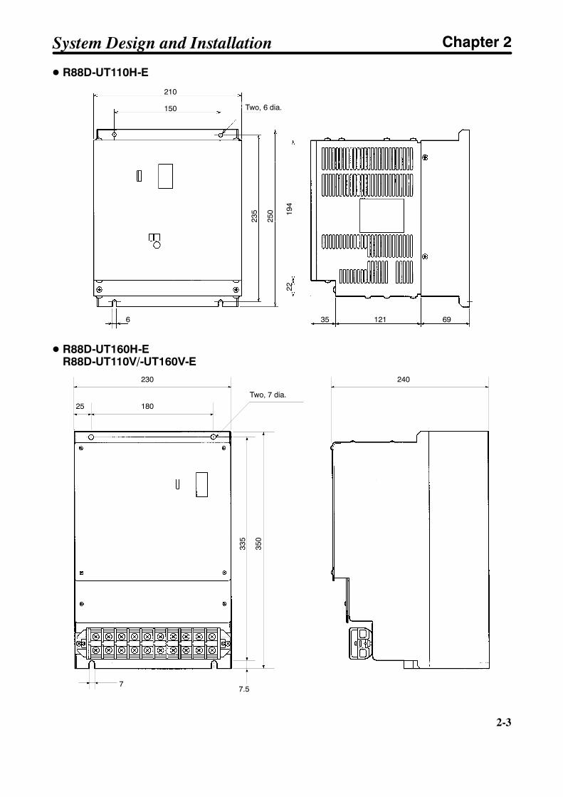
D R88D-UT110H-E
Two, 6 dia.
235
250
210
150
194
22
6 35 121 69
D R88D-UT160H-ER88D-UT110V/-UT160V-E
240
Two, 7 dia.
230
18025
77.5
335
350
System Design and Installation Chapter 2
2-4
2-4
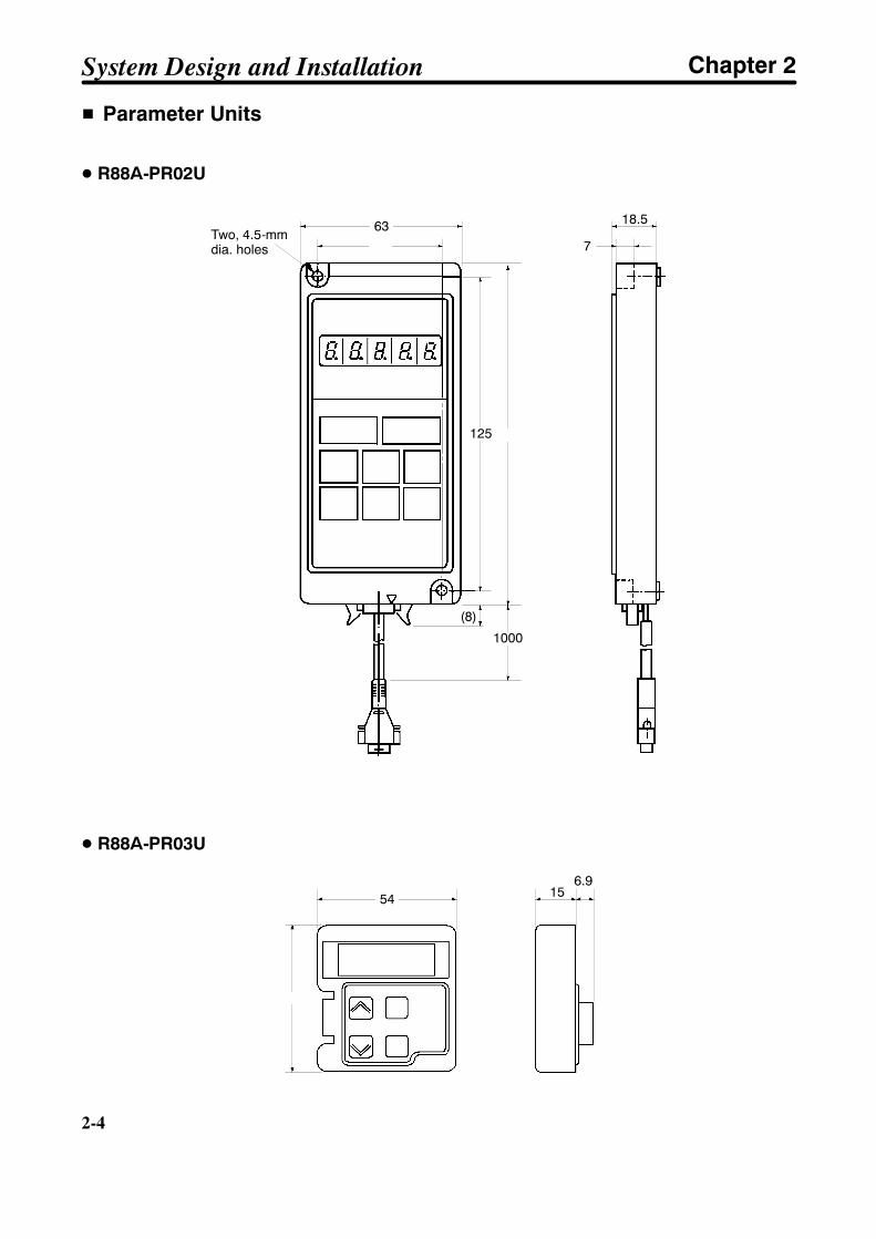
H Parameter Units
D R88A-PR02U
6350
(8)
1000
135125
7
18.5Two, 4.5-mmdia. holes
D R88A-PR03U
54
57.5
156.9
System Design and Installation Chapter 2
2-5
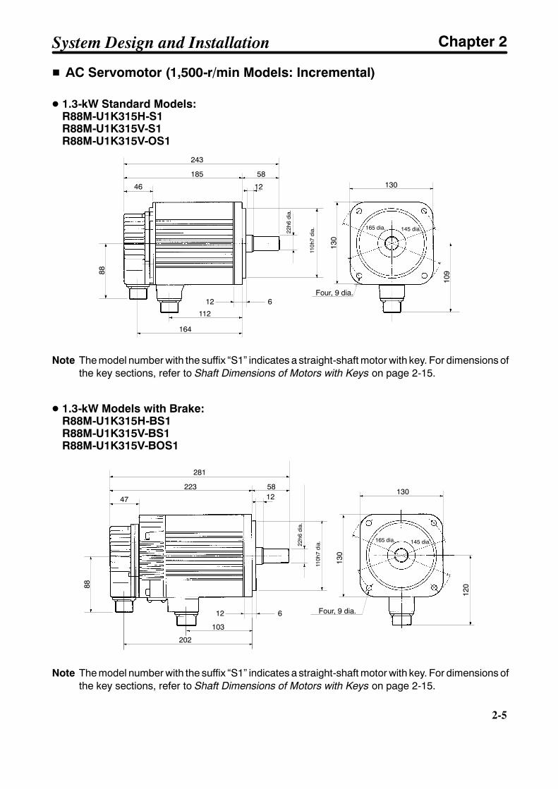
H AC Servomotor (1,500-r/min Models: Incremental)
D 1.3-kW Standard Models:R88M-U1K315H-S1R88M-U1K315V-S1R88M-U1K315V-OS1
243
185
46
12 6
58
145 dia.165 dia.
130
130
109
Four, 9 dia.
88
22h6
dia.
110h
7di
a.112
164
12
Note The model number with the suffix “S1” indicates a straight-shaft motor with key. For dimensions ofthe key sections, refer to Shaft Dimensions of Motors with Keys on page 2-15.
D 1.3-kW Models with Brake:R88M-U1K315H-BS1R88M-U1K315V-BS1R88M-U1K315V-BOS1
281
223
47
12 6
58
145 dia.165 dia.
130
130
Four, 9 dia.
88
120
22h6
dia.
110h
7di
a.
103
202
12
Note The model number with the suffix “S1” indicates a straight-shaft motor with key. For dimensions ofthe key sections, refer to Shaft Dimensions of Motors with Keys on page 2-15.
System Design and Installation Chapter 2

2-6
2-6
D 1.8-kW/2.9-kW/4.4-kW Standard Models:R88M-U1K815H-S1/-U2K915H-S1/-U4K415H-S1R88M-U1K815V-S1/-U2K915V-S1/-U4K415V-S1R88M-U1K815V-OS1/-U2K915V-OS1/-U4K415V-OS1
L
LL
47
18 3.2
79
200 dia.230 dia.
180
180
Four, 13.5 dia.
88
140
35h6
dia.
114.
3h7
dia.
KA
KB
Note The model number with the suffix “S1” indicates a straight-shaft motor with key. For dimensions ofthe key sections, refer to Shaft Dimensions of Motors with Keys on page 2-15.
D 1.8-kW/2.9-kW/4.4-kW Models with Brake:R88M-U1K815H-BS1/-U2K915H-BS1/-U4K415H-BS1R88M-U1K815V-BS1/-U2K915V-BS1/-U4K415V-BS1R88M-U1K815V-BOS1/-U2K915V-BOS1/-U4K415V-BOS1
88
18 3.2
47
79
200 dia.230 dia.
180
180
Four, 13.5 dia.
146
35h6
dia.
114.
3h7
dia.
KAKB
LLL
Note The model number with the suffix “S1” indicates a straight-shaft motor with key. For dimensions ofthe key sections, refer to Shaft Dimensions of Motors with Keys on page 2-15.
Standard Models
Model L LL KA KBR88M-U1K815j-jS1 245 166 89 145R88M-U2K915j-jS1 271 192 115 171R88M-U4K415j-jS1 305 226 149 205
Models with Brake
Model L LL KA KBR88M-U1K815j-BjS1 296 217 79 196R88M-U2K915j-BjS1 322 243 105 222R88M-U4K415j-BjS1 356 277 139 256
System Design and Installation Chapter 2

2-7
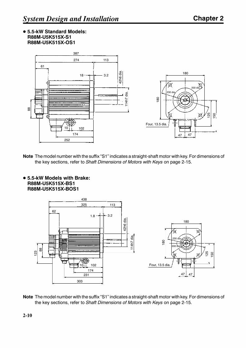
D 5.5-kW Standard Models:R88M-U5K515H-S1R88M-U5K515V-S1R88M-U5K515V-OS1
373
260
4718 3.2
113
200 dia.230 dia.
180
180
125
Four, 13.5 dia.
88
150
10210
47 4742
h6di
a.
114.
3h7
dia.
174239
Note The model number with the suffix “S1” indicates a straight-shaft motor with key. For dimensions ofthe key sections, refer to Shaft Dimensions of Motors with Keys on page 2-15.
D 5.5-kW Models with Brake:R88M-U5K515H-BS1R88M-U5K515V-BS1R88M-U5K515V-BOS1
424
311
4718 3.2
113
200 dia.230 dia.
180
180
125
Four, 13.5 dia.
88
150
10210
47 47
123
114.
3h7
dia.
42h6
dia.
174231
290
Note The model number with the suffix “S1” indicates a straight-shaft motor with key. For dimensions ofthe key sections, refer to Shaft Dimensions of Motors with Keys on page 2-15.
System Design and Installation Chapter 2
2-8
2-8
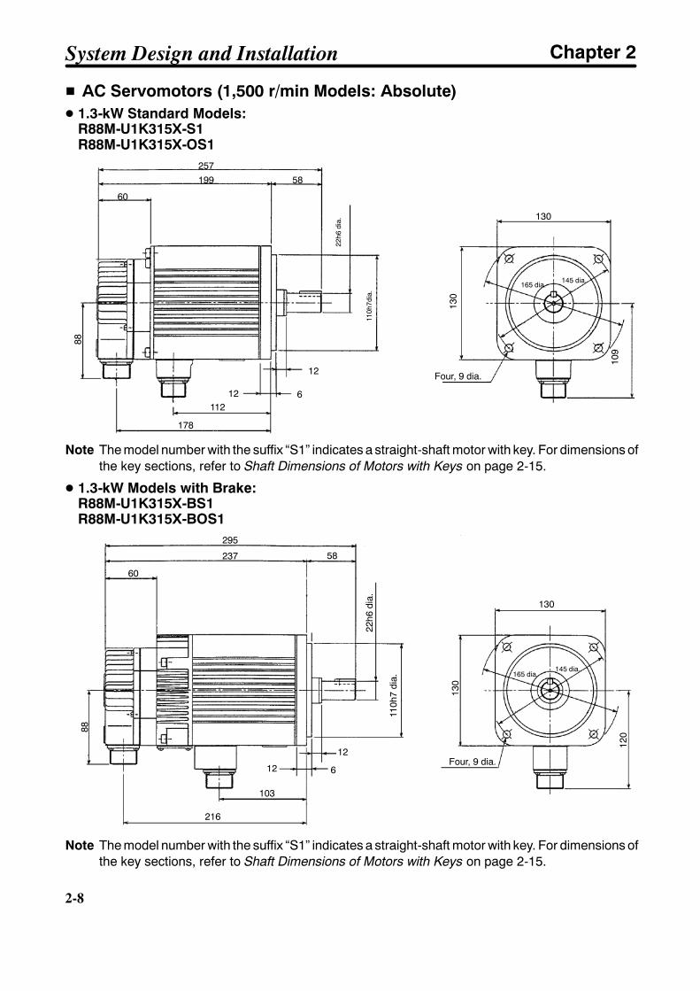
H AC Servomotors (1,500 r/min Models: Absolute)D 1.3-kW Standard Models:
R88M-U1K315X-S1R88M-U1K315X-OS1
178
11212 6
60
199257
58
88
130
130
Four, 9 dia.
109
145 dia.165 dia.
110h
7dia
.
22h6
dia.
12
Note The model number with the suffix “S1” indicates a straight-shaft motor with key. For dimensions ofthe key sections, refer to Shaft Dimensions of Motors with Keys on page 2-15.
D 1.3-kW Models with Brake:R88M-U1K315X-BS1R88M-U1K315X-BOS1
Four, 9 dia.
120
130
130
295
237 58
60
88
216
103
12 6
110h
7di
a.
22h6
dia.
145 dia.165 dia.
12
Note The model number with the suffix “S1” indicates a straight-shaft motor with key. For dimensions ofthe key sections, refer to Shaft Dimensions of Motors with Keys on page 2-15.
System Design and Installation Chapter 2

2-9
D 1.8-kW/2.9-kW/4.4-kW Standard Models:R88M-U1K815X-S1/-U2K915X-S1/-U4K415X-S1R88M-U1K815X-OS1/-U2K915X-OS1/-U4K415X-OS1
L
LL
KA
KB
Four, 13.5 dia.
88
180
140
114h
7di
a.
35h6
dia.
61
180
230 dia.
200 dia.
79
18 3.2
Note The model number with the suffix “S1” indicates a straight-shaft motor with key. For dimensions ofthe key sections, refer to Shaft Dimensions of Motors with Keys on page 2-15.
D 1.8-kW/2.9-kW/4.4-kW Models with Brake:R88M-U1K815X-BS1/-U2K915X-BS1/-U4K415X-BS1R88M-U1K815X-BOS1/-U2K915X-BOS1/-U4K415X-BOS1
LLL
6279
KA
KB
88
114h
7di
a.
35h6
dia.
Four, 13.5 dia.
146
180
180
230 dia.
200 dia.
18 3.2
Note The model number with the suffix “S1” indicates a straight-shaft motor with key. For dimensions ofthe key sections, refer to Shaft Dimensions of Motors with Keys on page 2-15.
Standard Models
Model L LL KA KBR88M-U1K815X-jS1 259 180 89 159R88M-U2K915X-jS1 285 206 115 184R88M-U4K415X-jS1 319 240 149 218
Models with Brake
Model L LL KA KBR88M-U1K815X-BjS1 310 231 79 209R88M-U2K915X-BjS1 336 257 105 235R88M-U4K415X-BjS1 370 291 139 269
System Design and Installation Chapter 2
2-10
2-10
D 5.5-kW Standard Models:R88M-U5K515X-S1R88M-U5K515X-OS1
387
274
61
113
3.218
10210
174
252
88
114h
7di
a.
42h6
dia.
Four, 13.5 dia.
47 47
125
150
180
180
230 dia.
200 dia.
Note The model number with the suffix “S1” indicates a straight-shaft motor with key. For dimensions ofthe key sections, refer to Shaft Dimensions of Motors with Keys on page 2-15.
D 5.5-kW Models with Brake:R88M-U5K515X-BS1R88M-U5K515X-BOS1
438
325
62
113
3.21.8
8812
3
10210
231174
303
114h
7di
a.
42h6
dia.
Four, 13.5 dia.
47 47
150
125
180
180
230 dia.
200 dia.
Note The model number with the suffix “S1” indicates a straight-shaft motor with key. For dimensions ofthe key sections, refer to Shaft Dimensions of Motors with Keys on page 2-15.
System Design and Installation Chapter 2
2-11
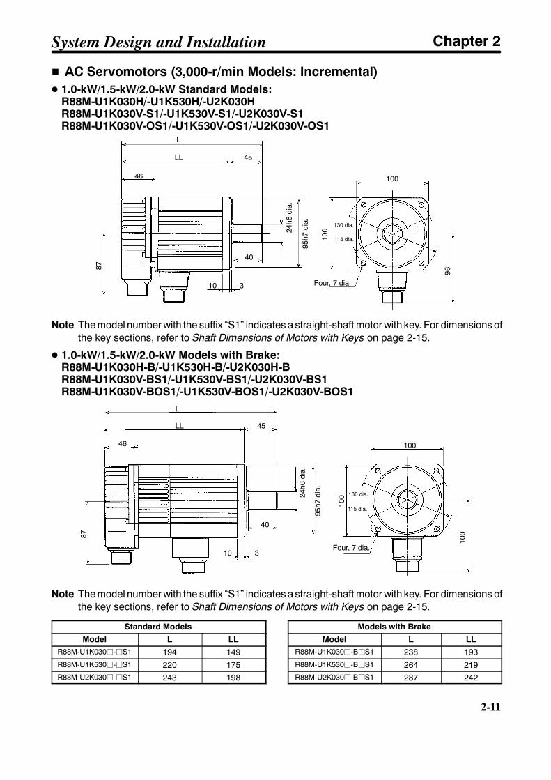
H AC Servomotors (3,000-r/min Models: Incremental)D 1.0-kW/1.5-kW/2.0-kW Standard Models:
R88M-U1K030H/-U1K530H/-U2K030HR88M-U1K030V-S1/-U1K530V-S1/-U2K030V-S1R88M-U1K030V-OS1/-U1K530V-OS1/-U2K030V-OS1
24h6
dia.
95h7
dia. 130 dia.
115 dia.
Four, 7 dia.
L
LL 45
46
87
10 3
40
100
96
100
Note The model number with the suffix “S1” indicates a straight-shaft motor with key. For dimensions ofthe key sections, refer to Shaft Dimensions of Motors with Keys on page 2-15.
D 1.0-kW/1.5-kW/2.0-kW Models with Brake:R88M-U1K030H-B/-U1K530H-B/-U2K030H-BR88M-U1K030V-BS1/-U1K530V-BS1/-U2K030V-BS1R88M-U1K030V-BOS1/-U1K530V-BOS1/-U2K030V-BOS1
130 dia.
115 dia.
Four, 7 dia.
L
LL 45
46
24h6
dia.
95h7
dia.
87
100
40
10 3
100
100
Note The model number with the suffix “S1” indicates a straight-shaft motor with key. For dimensions ofthe key sections, refer to Shaft Dimensions of Motors with Keys on page 2-15.
Standard Models
Model L LLR88M-U1K030j-jS1 194 149R88M-U1K530j-jS1 220 175R88M-U2K030j-jS1 243 198
Models with Brake
Model L LLR88M-U1K030j-BjS1 238 193R88M-U1K530j-BjS1 264 219R88M-U2K030j-BjS1 287 242
System Design and Installation Chapter 2

2-12
2-12
D 3.0-kW/4.0-kW/5.0-kW Standard Models:R88M-U3K030H/-U4K030H/-U5K030HR88M-U3K030V-S1/-U4K030V-S1/-U5K030V-S188M-U3K030V-OS1/-U4K030V-OS1/-U5K030V-OS1
165 dia.
145 dia.
28h6
dia.
110h
7di
a.
Four, 9 dia.
L
LL 63
46
87
12 6
55
130
130
114
Note The model number with the suffix “S1” indicates a straight-shaft motor with key. For dimensions ofthe key sections, refer to Shaft Dimensions of Motors with Keys on page 2-15.
D 3.0-kW/4.0-kW/5.0-kW Models with Brake:R88M-U3K030H-B/-U4K030H-B/-U5K030H-BR88M-U3K030V-BS1/-U4K030V-BS1/-U5K030V-BS1R88M-U3K030V-BOS1/-U4K030V-BOS1/-U5K030V-BOS1
165 dia.
145 dia.
28h6
dia.
110h
7di
a.
Four, 9 dia.
L
LL 63
46
87
12 6
55
130
130
119
Note The model number with the suffix “S1” indicates a straight-shaft motor with key. For dimensions ofthe key sections, refer to Shaft Dimensions of Motors with Keys on page 2-15.
Standard Models
Model L LL
R88M-U3K030j-jS1 262 199
R88M-U4K030j-jS1 299 236
R88M-U5K030j-jS1 339 276
Models with Brake
Model L LL
R88M-U3K030j-BjS1 300 237
R88M-U4K030j-BjS1 337 274
R88M-U5K030j-BjS1 377 314
System Design and Installation Chapter 2
2-13
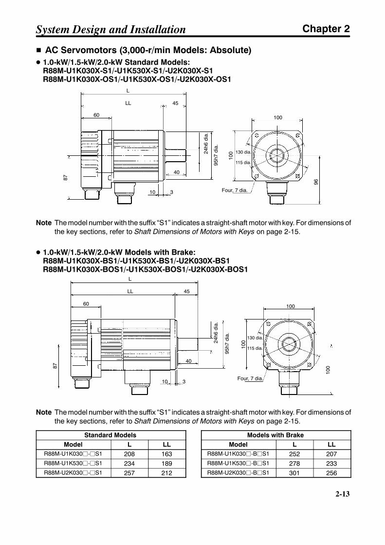
H AC Servomotors (3,000-r/min Models: Absolute)D 1.0-kW/1.5-kW/2.0-kW Standard Models:
R88M-U1K030X-S1/-U1K530X-S1/-U2K030X-S1R88M-U1K030X-OS1/-U1K530X-OS1/-U2K030X-OS1
Four, 7 dia.
95h7
dia.
130 dia.
115 dia.
24h6
dia.
L
LL 45
60
87
10 3
40
100
100
96
Note The model number with the suffix “S1” indicates a straight-shaft motor with key. For dimensions ofthe key sections, refer to Shaft Dimensions of Motors with Keys on page 2-15.
D 1.0-kW/1.5-kW/2.0-kW Models with Brake:R88M-U1K030X-BS1/-U1K530X-BS1/-U2K030X-BS1R88M-U1K030X-BOS1/-U1K530X-BOS1/-U2K030X-BOS1
Four, 7 dia.
95h7
dia. 130 dia.
115 dia.
24h6
dia.
L
LL 45
60
87
10 3
40
100
100
100
Note The model number with the suffix “S1” indicates a straight-shaft motor with key. For dimensions ofthe key sections, refer to Shaft Dimensions of Motors with Keys on page 2-15.
Standard ModelsModel L LL
R88M-U1K030j-jS1 208 163R88M-U1K530j-jS1 234 189R88M-U2K030j-jS1 257 212
Models with BrakeModel L LL
R88M-U1K030j-BjS1 252 207R88M-U1K530j-BjS1 278 233R88M-U2K030j-BjS1 301 256
System Design and Installation Chapter 2
2-14
2-14
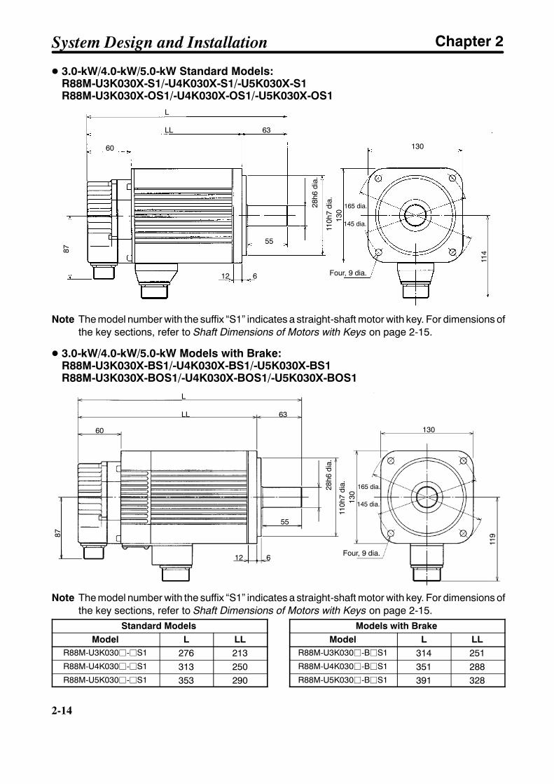
D 3.0-kW/4.0-kW/5.0-kW Standard Models:R88M-U3K030X-S1/-U4K030X-S1/-U5K030X-S1R88M-U3K030X-OS1/-U4K030X-OS1/-U5K030X-OS1
Four, 9 dia.
165 dia.
145 dia.
28h6
dia.
110h
7di
a.
L
LL 63
60
87
12 6
55
130
130
114
Note The model number with the suffix “S1” indicates a straight-shaft motor with key. For dimensions ofthe key sections, refer to Shaft Dimensions of Motors with Keys on page 2-15.
D 3.0-kW/4.0-kW/5.0-kW Models with Brake:R88M-U3K030X-BS1/-U4K030X-BS1/-U5K030X-BS1R88M-U3K030X-BOS1/-U4K030X-BOS1/-U5K030X-BOS1
Four, 9 dia.
165 dia.
145 dia.
28h6
dia.
110h
7di
a.
L
LL 63
60
87
12 6
55
130
130
119
Note The model number with the suffix “S1” indicates a straight-shaft motor with key. For dimensions ofthe key sections, refer to Shaft Dimensions of Motors with Keys on page 2-15.
Standard ModelsModel L LL
R88M-U3K030j-jS1 276 213R88M-U4K030j-jS1 313 250R88M-U5K030j-jS1 353 290
Models with BrakeModel L LL
R88M-U3K030j-BjS1 314 251R88M-U4K030j-BjS1 351 288R88M-U5K030j-BjS1 391 328
System Design and Installation Chapter 2
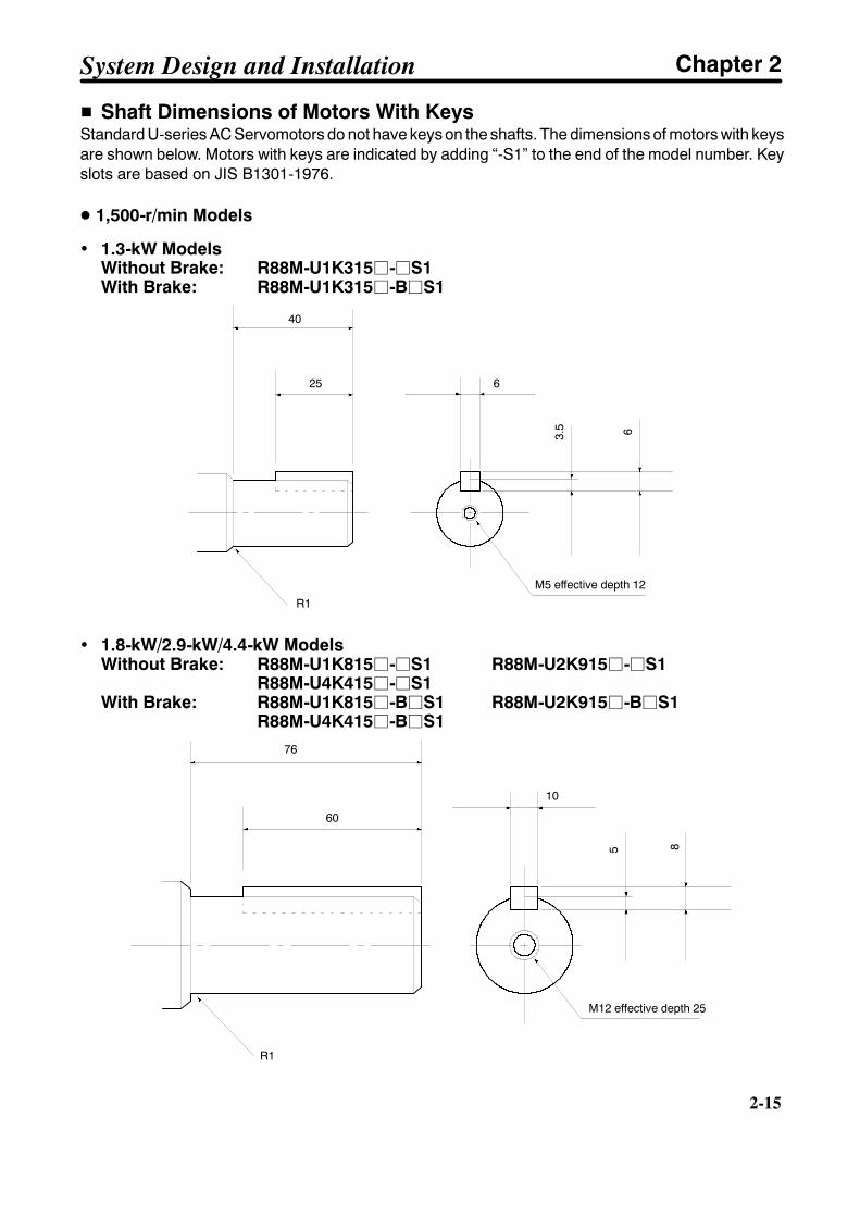
2-15
H Shaft Dimensions of Motors With KeysStandard U-series AC Servomotors do not have keys on the shafts. The dimensions of motors with keysare shown below. Motors with keys are indicated by adding “-S1” to the end of the model number. Keyslots are based on JIS B1301-1976.
D 1,500-r/min Models
• 1.3-kW ModelsWithout Brake: R88M-U1K315j-jS1With Brake: R88M-U1K315j-BjS1
40
25 6
3.5 6
R1
M5 effective depth 12
• 1.8-kW/2.9-kW/4.4-kW ModelsWithout Brake: R88M-U1K815j-jS1 R88M-U2K915j-jS1
R88M-U4K415j-jS1With Brake: R88M-U1K815j-BjS1 R88M-U2K915j-BjS1
R88M-U4K415j-BjS176
60
10
5 8
R1
M12 effective depth 25
System Design and Installation Chapter 2
2-16
2-16
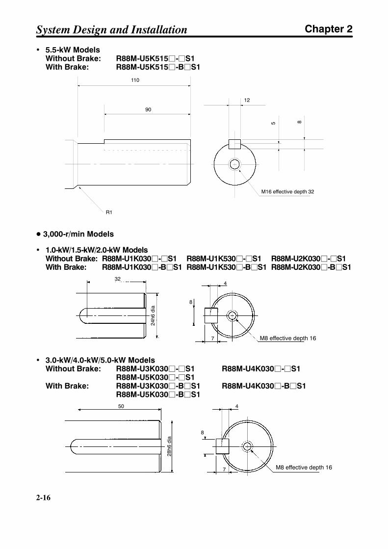
• 5.5-kW ModelsWithout Brake: R88M-U5K515j-jS1With Brake: R88M-U5K515j-BjS1
110
90
12
5 8
R1
M16 effective depth 32
D 3,000-r/min Models
• 1.0-kW/1.5-kW/2.0-kW ModelsWithout Brake: R88M-U1K030j-jS1 R88M-U1K530j-jS1 R88M-U2K030j-jS1With Brake: R88M-U1K030j-BjS1 R88M-U1K530j-BjS1 R88M-U2K030j-BjS1
M8 effective depth 16
24h6
dia
324
8
7
• 3.0-kW/4.0-kW/5.0-kW ModelsWithout Brake: R88M-U3K030j-jS1 R88M-U4K030j-jS1
R88M-U5K030j-jS1With Brake: R88M-U3K030j-BjS1 R88M-U4K030j-BjS1
R88M-U5K030j-BjS1
M8 effective depth 16
28h6
dia
50 4
8
7
System Design and Installation Chapter 2
2-17
2-1-2 Installation Conditions
H AC Servo Drivers
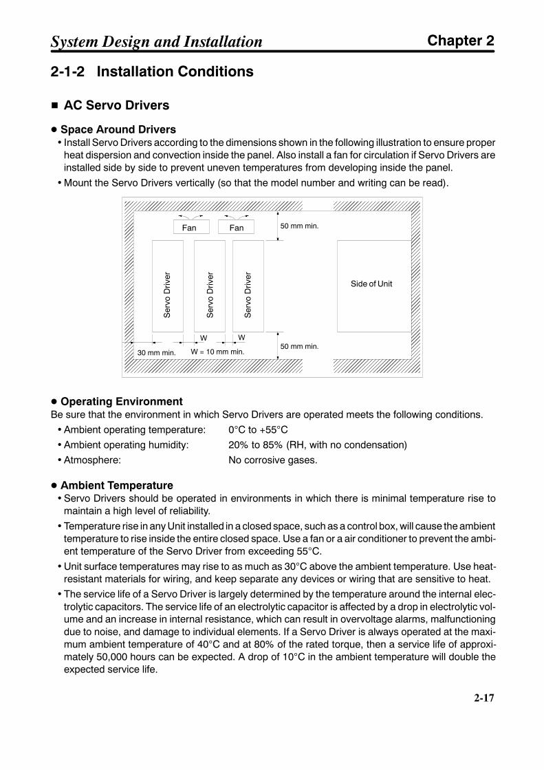
D Space Around Drivers• Install Servo Drivers according to the dimensions shown in the following illustration to ensure proper
heat dispersion and convection inside the panel. Also install a fan for circulation if Servo Drivers areinstalled side by side to prevent uneven temperatures from developing inside the panel.
• Mount the Servo Drivers vertically (so that the model number and writing can be read).
50 mm min.
50 mm min.W W
30 mm min.
Fan Fan
Ser
voD
river
W = 10 mm min.
Side of Unit
Ser
voD
river
Ser
voD
river
D Operating EnvironmentBe sure that the environment in which Servo Drivers are operated meets the following conditions.
• Ambient operating temperature: 0°C to +55°C• Ambient operating humidity: 20% to 85% (RH, with no condensation)• Atmosphere: No corrosive gases.
D Ambient Temperature• Servo Drivers should be operated in environments in which there is minimal temperature rise to
maintain a high level of reliability.• Temperature rise in any Unit installed in a closed space, such as a control box, will cause the ambient
temperature to rise inside the entire closed space. Use a fan or a air conditioner to prevent the ambi-ent temperature of the Servo Driver from exceeding 55°C.
• Unit surface temperatures may rise to as much as 30°C above the ambient temperature. Use heat-resistant materials for wiring, and keep separate any devices or wiring that are sensitive to heat.
• The service life of a Servo Driver is largely determined by the temperature around the internal elec-trolytic capacitors. The service life of an electrolytic capacitor is affected by a drop in electrolytic vol-ume and an increase in internal resistance, which can result in overvoltage alarms, malfunctioningdue to noise, and damage to individual elements. If a Servo Driver is always operated at the maxi-mum ambient temperature of 40°C and at 80% of the rated torque, then a service life of approxi-mately 50,000 hours can be expected. A drop of 10°C in the ambient temperature will double theexpected service life.
System Design and Installation Chapter 2
2-18
2-18
D Keeping Foreign Objects Out of Units• Place a cover over the Units or take other preventative measures to prevent foreign objects, such as
drill filings, from getting into the Units during installation. Be sure to remove the cover after installa-tion is complete. If the cover is left on during operation, heat buildup may damage the Units.
• Take measures during installation and operation to prevent foreign objects such as metal particles,oil, machining oil, dust, or water from getting inside of Servo Drivers.
H AC Servomotors
D Operating EnvironmentBe sure that the environment in which the Servomotor is operated meets the following conditions.
• Ambient operating temperature: 0°C to +40°C
• Ambient operating humidity: 20% to 80% (RH, with no condensation)
• Atmosphere: No corrosive gases.
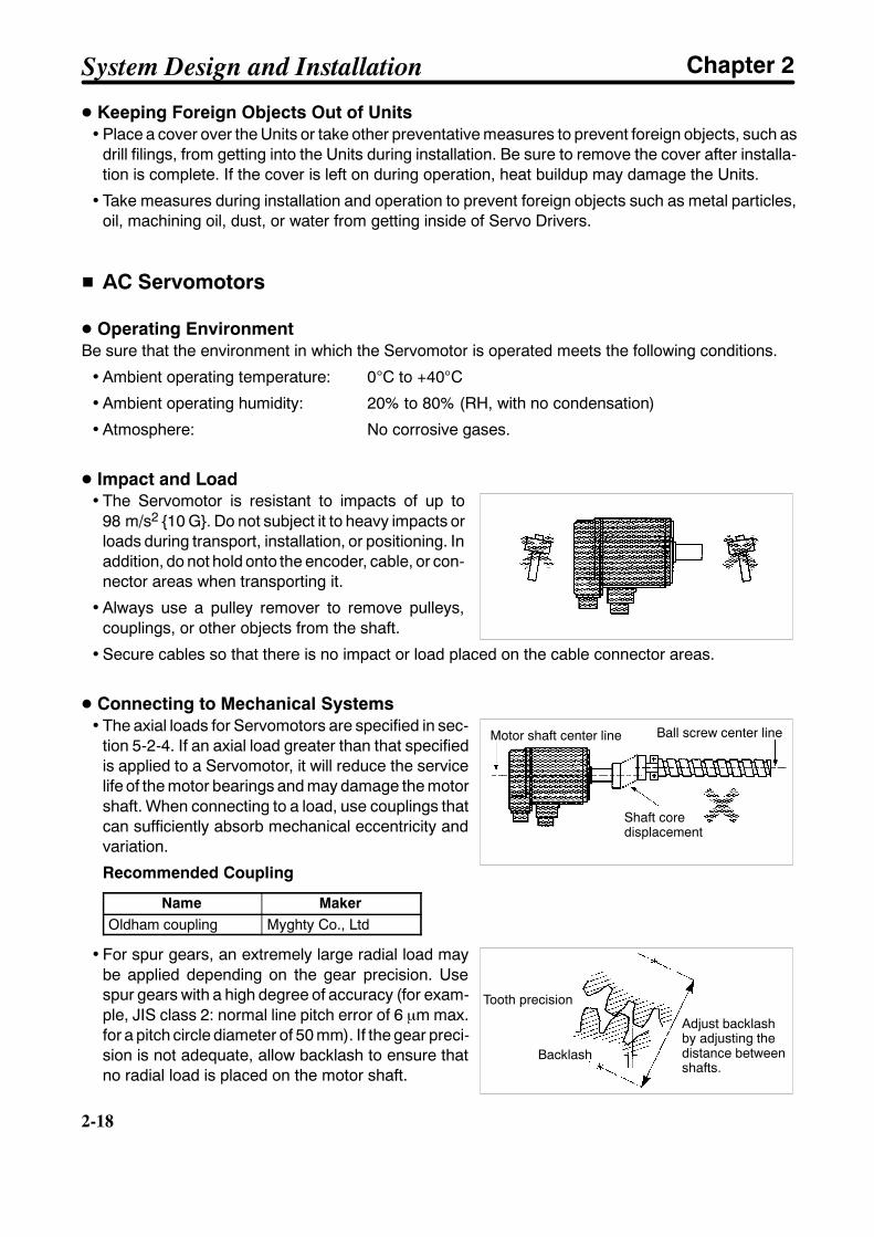
D Impact and Load• The Servomotor is resistant to impacts of up to
98 m/s2 10 G. Do not subject it to heavy impacts orloads during transport, installation, or positioning. Inaddition, do not hold onto the encoder, cable, or con-nector areas when transporting it.
• Always use a pulley remover to remove pulleys,couplings, or other objects from the shaft.
• Secure cables so that there is no impact or load placed on the cable connector areas.
D Connecting to Mechanical Systems• The axial loads for Servomotors are specified in sec-
tion 5-2-4. If an axial load greater than that specifiedis applied to a Servomotor, it will reduce the servicelife of the motor bearings and may damage the motorshaft. When connecting to a load, use couplings thatcan sufficiently absorb mechanical eccentricity andvariation.
Recommended Coupling
Name MakerOldham coupling Myghty Co., Ltd
• For spur gears, an extremely large radial load maybe applied depending on the gear precision. Usespur gears with a high degree of accuracy (for exam-ple, JIS class 2: normal line pitch error of 6 µm max.for a pitch circle diameter of 50 mm). If the gear preci-sion is not adequate, allow backlash to ensure thatno radial load is placed on the motor shaft.
Ball screw center lineMotor shaft center line
Shaft coredisplacement
Tooth precision
Backlash
Adjust backlashby adjusting thedistance betweenshafts.
System Design and Installation Chapter 2
2-19
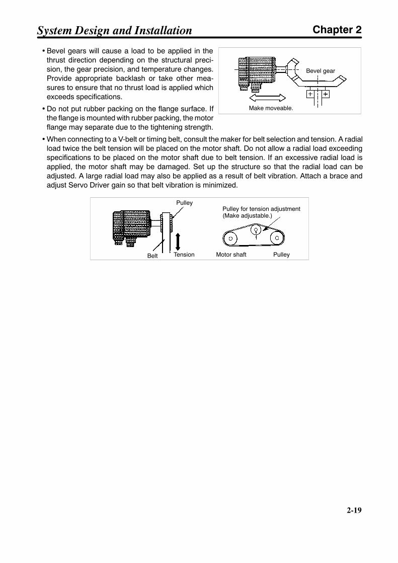
• Bevel gears will cause a load to be applied in thethrust direction depending on the structural preci-sion, the gear precision, and temperature changes.Provide appropriate backlash or take other mea-sures to ensure that no thrust load is applied whichexceeds specifications.
• Do not put rubber packing on the flange surface. Ifthe flange is mounted with rubber packing, the motorflange may separate due to the tightening strength.
• When connecting to a V-belt or timing belt, consult the maker for belt selection and tension. A radialload twice the belt tension will be placed on the motor shaft. Do not allow a radial load exceedingspecifications to be placed on the motor shaft due to belt tension. If an excessive radial load isapplied, the motor shaft may be damaged. Set up the structure so that the radial load can beadjusted. A large radial load may also be applied as a result of belt vibration. Attach a brace andadjust Servo Driver gain so that belt vibration is minimized.
Tension Motor shaft
Pulley for tension adjustment(Make adjustable.)
Pulley
Pulley
Belt
Make moveable.
Bevel gear
System Design and Installation Chapter 2
2-20
2-20
D Water and Drip Resistance• The Servomotor is not of waterproof construction.
The Servomotor is provided with either of the following protection.
Models not complying with EC Directives: IP65 (excluding the shaft penetration areas)Models complying with EC Directives: IP55 (including the shaft penetration areas)
The standard cable conforms to IP30. If the Power Cable or Encoder Cable is used in places wetwith sprayed water, connect waterproof connectors to the Cable.If the equipment incorporating the Servomotor must comply with EC Directives, connect the follow-ing connectors to the Power Cable and Encoder Cable.
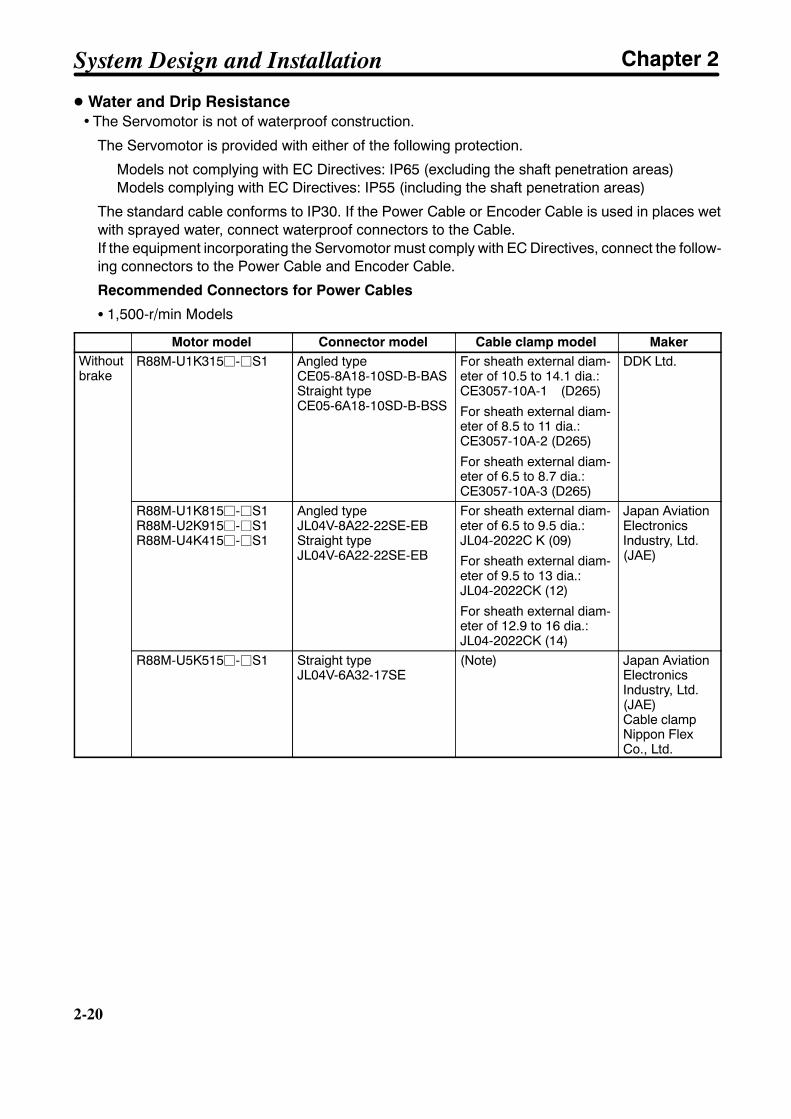
Recommended Connectors for Power Cables
S 1,500-r/min Models
Motor model Connector model Cable clamp model MakerWithoutbrake
R88M-U1K315j-jS1 Angled typeCE05-8A18-10SD-B-BASStraight typeCE05-6A18-10SD-B-BSS
For sheath external diam-eter of 10.5 to 14.1 dia.:CE3057-10A-1 (D265)
For sheath external diam-eter of 8.5 to 11 dia.:CE3057-10A-2 (D265)
For sheath external diam-eter of 6.5 to 8.7 dia.:CE3057-10A-3 (D265)
DDK Ltd.
R88M-U1K815j-jS1R88M-U2K915j-jS1R88M-U4K415j-jS1
Angled typeJL04V-8A22-22SE-EBStraight typeJL04V-6A22-22SE-EB
For sheath external diam-eter of 6.5 to 9.5 dia.:JL04-2022C K (09)
For sheath external diam-eter of 9.5 to 13 dia.:JL04-2022CK (12)
For sheath external diam-eter of 12.9 to 16 dia.:JL04-2022CK (14)
Japan AviationElectronicsIndustry, Ltd.(JAE)
R88M-U5K515j-jS1 Straight typeJL04V-6A32-17SE
(Note) Japan AviationElectronicsIndustry, Ltd.(JAE)Cable clampNippon FlexCo., Ltd.
System Design and Installation Chapter 2

2-21
MakerCable clamp modelConnector modelMotor modelWithbrake
R88M-U1K315j-BjS1 Angled typeJL04V-8A20-15SE-EBStraight typeJL04V-6A20-15SE-EB
For sheath external diam-eter of 6.5 to 9.5 dia. :JL04-2022C K (09)
For sheath external diam-eter of 9.5 to 13 dia. :JL04-2022C K (12)
For sheath external diam-eter of 12.5 to 15.9 dia. :JL04-2022C K (14)
Japan AviationElectronicsIndustry, Ltd.(JAE)
R88M-U1K815j-BjS1R88M-U2K915j-BjS1R88M-U4K415j-BjS1
Angled typeJL04V-8A24-10SE-EBStraight typeJL04V-6A24-10SE-EB
For sheath external diam-eter of 9 to 12 dia. :JL04-2428C K (11)
For sheath external diam-eter of 12 to 15 dia. :JL04-2428C K (14)
For sheath external diam-eter of 15 to 18 dia. :JL04-2428C K (17)
For sheath external diam-eter of 18 to 20 dia. :JL04-2428C K (20)
Japan AviationElectronicsIndustry, Ltd.(JAE)
R88M-U5K515j-BjS1
Formotivepower
Straight typeJL04V-6A32-17SE
(See note) Japan AviationElectronicsIndustry, Ltd.(JAE)Cable clampNippon FlexCo., Ltd.
Forbrak-ing
Angled typeCE05-8A10SL-3SC-B-BASStraight typeCE-05-6A10SL-3SC-B-BSS
For sheath external diam-eter of 3.6 to 5.6 dia.:CE3057-4A-1 (D265)
DDK Ltd.
NoteAngle Straight Applicable cable diameter
ACA-16RL-MS32F ACS-16RL-MS32F 12 to 16 dia.ACA-20RL-MS32F ACS-20RL-MS32F 16 to 20 dia.ACA-24RL-MS32F ACS-24RL-MS32F 20 to 24 dia.ACA-28RL-MS32F ACS-28RL-MS32F 24 to 28 dia.ACA-32RL-MS32F ACS-32RL-MS32F 28 to 32 dia.ACA-36RL-MS32F ACS-36RL-MS32F 32 to 36 dia.
System Design and Installation Chapter 2

2-22
2-22
S 3,000-r/min Model
Motor model Connector model Cable clamp model MakerWithoutbrake
R88M-U1K030j-jR88M-U1K530j-jR88M-U2K030j-j
Angled typeCE05-8A18-10SD-B-BASStraight typeCE05-6A18-10SD-B-BSS
For sheath external diam-eter of 6.5 to 8.7 dia.:CE3057-10A-3 (D265)
For sheath external diam-eter of 8.5 to 11 dia.:CE3057-10A-2 (D265)
For sheath external diam-eter of 10.5 to 14.1 dia.:CE3057-10A-1 (D265)
DDK Ltd.
R88M-U3K030j-jR88M-U4K030j-jR88M-U5K030j-j
Angled typeJL04V-8A22-22SE-EBStraight typeJL04V-6A22-22SE-EB
For sheath external diam-eter of 6.5 to 9.5 dia.:JL04-2022CK(09)
For sheath external diam-eter of 9.5 to 13 dia.:JL04-2022CK(12)
For sheath external diam-eter of 12.9 to 15.9 dia.:JL04-2022CK(14)
Japan AviationElectronics Indus-try, Ltd. (JAE)
Withbrake
R88M-U1K030j-BjR88M-U1K530j-BjR88M-U2K030j-Bj
Angled typeJL04V-8A20-15SE-EBStraight typeJL04V-6A20-15SE-EB
For sheath external diam-eter of 6.5 to 9.5 dia.:JL04-2022CK(09)
For sheath external diam-eter of 9.5 to 13 dia.:JL04-2022CK(12)
For sheath external diam-eter of 12.9 to 15.9 dia.:JL04-2022C K(14)
Japan AviationElectronics Indus-try, Ltd. (JAE)
R88M-U3K030j-BjR88M-U4K030j-BjR88M-U5K030j-Bj
Angled typeJL04V-8A24-10SE-EBStraight typeJL04V-6A24-10SE-EB
For sheath external diam-eter of 9 to 12 dia.:JL04-2428CK(11)
For sheath external diam-eter of 12 to 15 dia.:JL04-2428CK(14)
For sheath external diam-eter of 15 to 18 dia.:JL04-2428CK(17)
For sheath external diam-eter of 18 to 20 dia.:JL04-2428CK(20)
Japan AviationElectronics Indus-try, Ltd. (JAE)
System Design and Installation Chapter 2
2-23
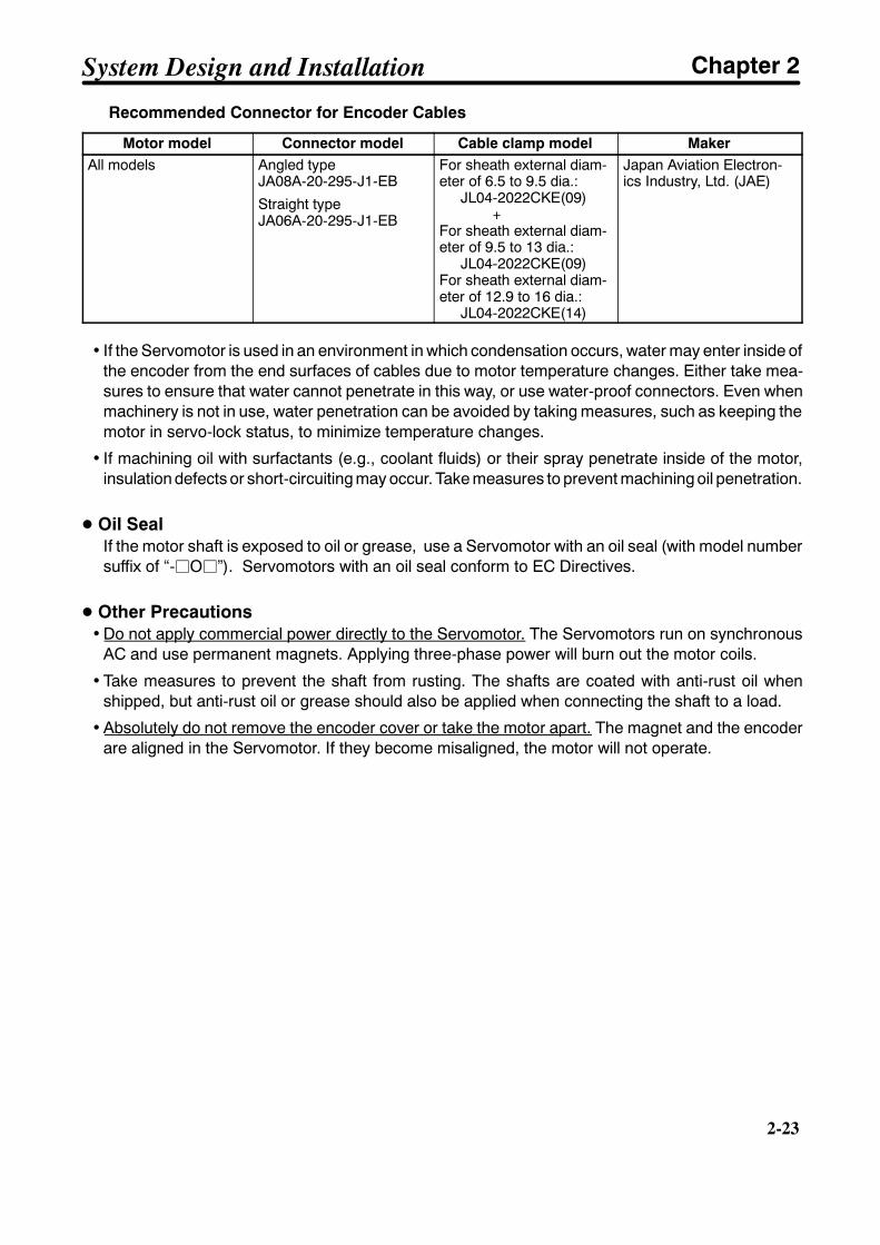
Recommended Connector for Encoder Cables
Motor model Connector model Cable clamp model MakerAll models Angled type
JA08A-20-295-J1-EB
Straight typeJA06A-20-295-J1-EB
For sheath external diam-eter of 6.5 to 9.5 dia.:
JL04-2022CKE(09)+
For sheath external diam-eter of 9.5 to 13 dia.:
JL04-2022CKE(09)For sheath external diam-eter of 12.9 to 16 dia.:
JL04-2022CKE(14)
Japan Aviation Electron-ics Industry, Ltd. (JAE)
• If the Servomotor is used in an environment in which condensation occurs, water may enter inside ofthe encoder from the end surfaces of cables due to motor temperature changes. Either take mea-sures to ensure that water cannot penetrate in this way, or use water-proof connectors. Even whenmachinery is not in use, water penetration can be avoided by taking measures, such as keeping themotor in servo-lock status, to minimize temperature changes.
• If machining oil with surfactants (e.g., coolant fluids) or their spray penetrate inside of the motor,insulation defects or short-circuiting may occur. Take measures to prevent machining oil penetration.
D Oil SealIf the motor shaft is exposed to oil or grease, use a Servomotor with an oil seal (with model numbersuffix of “-jOj”). Servomotors with an oil seal conform to EC Directives.
D Other Precautions• Do not apply commercial power directly to the Servomotor. The Servomotors run on synchronous
AC and use permanent magnets. Applying three-phase power will burn out the motor coils.
• Take measures to prevent the shaft from rusting. The shafts are coated with anti-rust oil whenshipped, but anti-rust oil or grease should also be applied when connecting the shaft to a load.
• Absolutely do not remove the encoder cover or take the motor apart. The magnet and the encoderare aligned in the Servomotor. If they become misaligned, the motor will not operate.
System Design and Installation Chapter 2
2-24
2-24
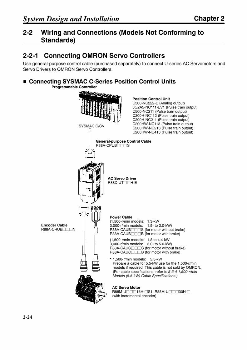
2-2 Wiring and Connections (Models Not Conforming toStandards)
2-2-1 Connecting OMRON Servo ControllersUse general-purpose control cable (purchased separately) to connect U-series AC Servomotors andServo Drivers to OMRON Servo Controllers.
H Connecting SYSMAC C-Series Position Control UnitsProgrammable Controller
Position Control UnitC500-NC222-E (Analog output)3G2A5-NC111-EV1 (Pulse train output)C500-NC211 (Pulse train output)C200H-NC112 (Pulse train output)C200H-NC211 (Pulse train output)C200HW-NC113 (Pulse train output)C200HW-NC213 (Pulse train output)C200HW-NC413 (Pulse train output)
General-purpose Control CableR88A-CPUBjjjS
Power Cable(1,500-r/min models: 1.3-kW3,000-r/min models: 1.5- to 2.0-kW)R88A-CAUBjjjS (for motor without brake)R88A-CAUBjjjB (for motor with brake)
(1,500-r/min models: 1.8 to 4.4-kW3,000-r/min models: 3.0- to 5.0-kW)R88A-CAUCjjjS (for motor without brake)R88A-CAUCjjjB (for motor with brake)
Encoder CableR88A-CRUBjjjN
AC Servo DriverR88D-UTjjH-E
SYSMAC C/CV
AC Servo MotorR88M-Ujjj15H-jS1, R88M-Ujjj30H-j(with incremental encoder)
* 1,500-r/min models: 5.5-kWPrepare a cable for 5.5-kW use for the 1,500-r/minmodels if required. This cable is not sold by OMRON.(For cable specifications, refer to 5-3-4 1,500-r/minModels (5.5-kW) Cable Specifications.)
System Design and Installation Chapter 2

2-25
H Connecting to SYSMAC C/CV-Series Motion Control Units
Programmable Controller
Motion Control UnitCV500-MC221 (Analog output)CV500-MC421 (Analog output)C200H-MC221 (Analog output)
General-purpose Control CableR88A-CPUBjjjM1 (for single axis)R88A-CPUBjjjM2 (for double axis)
Power Cable(1,500-r/min models: 1.3-kW3,000-r/min models: 1.5- to 2.0-kW)R88A-CAUBjjjS (for motor without brake)R88A-CAUBjjjB (for motor with brake)
(1,500-r/min models: 1.8 to 4.4-kW3,000-r/min models: 3.0- to 5.0-kW)R88A-CAUCjjjS (for motor without brake)R88A-CAUCjjjB (for motor with brake)
AC Servo DriverR88D-UTjjH-E
SYSMAC CV/CVM1
AC Servo MotorR88M-Ujjj15H-jS1R88M-Ujjj30H-j(with incremental encoder)
Encoder CableR88A-CRUBjjjN
* 1,500-r/min models: 5.5-kWPrepare a cable for 5.5-kW use for the 1,500-r/minmodels if required. This cable is not sold by OMRON.(For cable specifications, refer to 5-3-4 1,500-r/minModels (5.5-kW) Cable Specifications.)
Note Refer to Chapter 5 Specifications for connector and cable specifications.
System Design and Installation Chapter 2
2-26
2-26
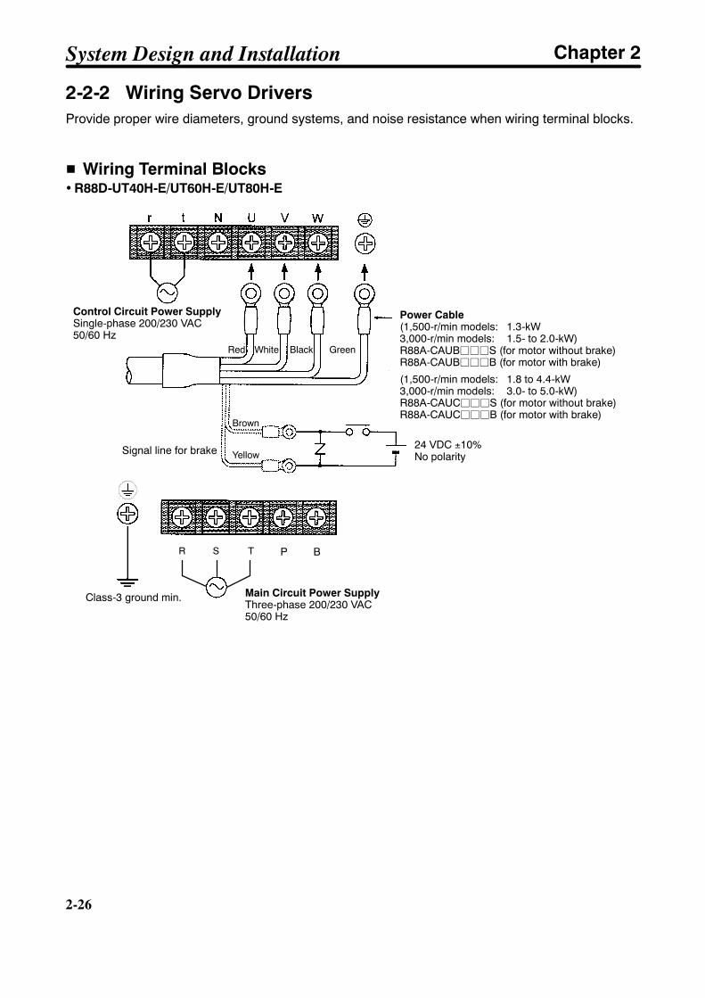
2-2-2 Wiring Servo DriversProvide proper wire diameters, ground systems, and noise resistance when wiring terminal blocks.
H Wiring Terminal Blocks• R88D-UT40H-E/UT60H-E/UT80H-E
Power Cable(1,500-r/min models: 1.3-kW3,000-r/min models: 1.5- to 2.0-kW)R88A-CAUBjjjS (for motor without brake)R88A-CAUBjjjB (for motor with brake)
(1,500-r/min models: 1.8 to 4.4-kW3,000-r/min models: 3.0- to 5.0-kW)R88A-CAUCjjjS (for motor without brake)R88A-CAUCjjjB (for motor with brake)
Control Circuit Power SupplySingle-phase 200/230 VAC50/60 Hz
Signal line for brake 24 VDC ±10%No polarity
Class-3 ground min. Main Circuit Power SupplyThree-phase 200/230 VAC50/60 Hz
Red White Black Green
Brown
Yellow
R S T P B
System Design and Installation Chapter 2

2-27
• R88D-UT110H-E
Power CableR88A-CAUCjjjS (for motor without brake)R88A-CAUCjjjB (for motor with brake)
Control Circuit Power SupplySingle-phase 200/230 VAC50/60 Hz
Signal line for brake24 VDC ±10%No polarity
Class-3 ground min.
Main Circuit PowerSupplyThree-phase200/230 VAC50/60 Hz
Red White Black Green
Brown
Yellow
• R88D-UT160H-E
* Prepare the power cables.C (Phase W)
B (Phase V)
A (Phase U)
D (GR)
RegenerativeResistance
WNPTSR VUBP1
tr
M
Main Circuit Power SupplyThree-phase 200/230 VAC50/60 Hz
Control Circuit Power SupplySingle-phase 200/230 VAC50/60 Hz
R R
Class-3 ground min.
Connector Pin No.
System Design and Installation Chapter 2
2-28
2-28
Terminallabel
Name Function
Frame ground This is the ground terminal. Ground to a class-3 ground (to 100 Ω or less) orbetter.
R Main circuitpower supply
Three-phase 200/230 VAC (170 to 253 V), 50/60 HzS
Main circuitpower supplyinput
Three-phase 200/230 VAC (170 to 253 V), 50/60 Hz
Tinput
r Control circuitpower supply
Single-phase 200/230 VAC (170 to 253 V), 50/60 Hz
tpower supplyinput
P1 Regenerativeresistorconnection
Regenerative resistor connection terminal for a Servo Driver of 5.5 kW min.(R88D-UT160H-E only)
Bresistorconnectionterminals
(R88D-UT160H-E only)
PN
Main circuit DCoutput
Do not connect anything to these terminals.
U Motor connectionterminals
Red These are the output terminals to the Servomotor. Be careful to wirethem correctly.V
Motor connectionterminals White
These are the output terminals to the Servomotor. Be careful to wirethem correctly.
W BlackFrame ground Green
Note Servo Drivers of 5.0 kW or less are not provided with the P1 terminal.
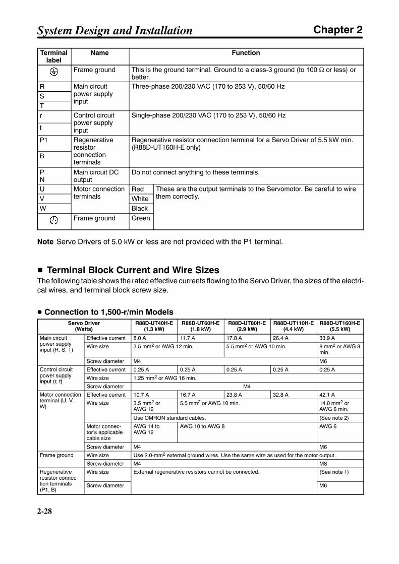
H Terminal Block Current and Wire SizesThe following table shows the rated effective currents flowing to the Servo Driver, the sizes of the electri-cal wires, and terminal block screw size.
D Connection to 1,500-r/min ModelsServo Driver
(Watts)R88D-UT40H-E
(1.3 kW)R88D-UT60H-E
(1.8 kW)R88D-UT80H-E
(2.9 kW)R88D-UT110H-E
(4.4 kW)R88D-UT160H-E
(5.5 kW)
Main circuitpower supply
Effective current 8.0 A 11.7 A 17.8 A 26.4 A 33.9 AMain circuitpower supplyinput (R, S, T)
Wire size 3.5 mm2 or AWG 12 min. 5.5 mm2 or AWG 10 min. 8 mm2 or AWG 8min.
Screw diameter M4 M6
Control circuitpower supply
Effective current 0.25 A 0.25 A 0.25 A 0.25 A 0.25 AControl circuitpower supplyinput (r, t)
Wire size 1.25 mm2 or AWG 16 min.input (r, t)
Screw diameter M4Motor connectionterminal (U, V,
Effective current 10.7 A 16.7 A 23.8 A 32.8 A 42.1 AMotor connectionterminal (U, V,W)
Wire size 3.5 mm2 orAWG 12
5.5 mm2 or AWG 10 min. 14.0 mm2 orAWG 6 min.
Use OMRON standard cables. (See note 2)
Motor connec-tor’s applicablecable size
AWG 14 toAWG 12
AWG 10 to AWG 8 AWG 6
Screw diameter M4 M6
Frame ground Wire size Use 2.0-mm2 external ground wires. Use the same wire as used for the motor output.Frame ground
Screw diameter M4 M8
Regenerativeresistor connec-tion terminals
Wire size External regenerative resistors cannot be connected. (See note 1)resistor connec-tion terminals(P1, B)
Screw diameter M6
System Design and Installation Chapter 2

2-29
Note 1. For the sizes of electrical wires to be connected to the regenerative resistor, refer to 3-6-2Servo Driver Absorbable Regenerative Energy.
Note 2. Prepare a 5.5-kw cable for the 1,500-r/min models if required. This cable is not sold byOMRON.
D Connection to 3,000-r/min ModelsServo Driver
(Watts)R88D-UT40H-E
(1.5 kW)R88D-UT60V
(2.0 kW)R88D-UT80H-E
(3.0 kW)R88D-UT110H-EServo Driver
(Watts)R88D-UT40H-E
(1.5 kW)R88D-UT60V
(2.0 kW)R88D-UT80H-E
(3.0 kW) (4.0 KW) (5.0 KW)
Main circuit powersupply input (R,
Effective current 9.2 A 13.0 A 18.4 A 24.0 A 28.0 Asupply input (R,S, T) Wire size 3.5 mm2 or AWG 12 min. 5.5 mm2 or AWG 10 min.
Control circuitpower supply
Effective current 0.25 A 0.25 A 0.25 A 0.25 A 0.25 Apower supplyinput (r, t) Wire size 1.25 mm2 or AWG 16 min.
Motor connectionterminal (U, V, W)
Effective current 9.9 A 12.0 A 19.4 A 25.3 A 26.2 AMotor connectionterminal (U, V, W) Wire size 3.5 mm2 or AWG 12 5.5 mm2 or AWG 10 min.Wire size
Use OMRON standard cables.
Motor connector’sapplicable cablesize
AWG 14 to AWG 12 AWG 10 to AWG 8
Frame ground Wire size Use 2.0-mm2 external ground wires. Use the same wire as used for the motor output.
Terminal block screw size M4
H Wire Sizes and Allowable CurrentThe following table shows allowable currents when there are three electrical wires. Use values equal toor lower than the specified values.
D 600-V Heat-resistant Vinyl Wiring (HIV) (Reference Values)AWG size Nominal cross-
sectional area(mm2)
Configuration(wires/mm2)
Conductiveresistance
(Ω/km)
Allowable current (A) forambient temperaturesectional area
(mm2)(wires/mm ) resistance
(Ω/km) 30°C 40°C 50°C16 1.25 7/0.45 17.5 16 14 1114 2.0 7/0.6 9.53 23 20 1612 3.5 7/0.8 5.41 33 29 2410 5.5 7/1.0 3.47 43 38 318 8.0 7/1.2 2.41 55 49 406 14.0 7/1.6 1.35 79 70 57
System Design and Installation Chapter 2
2-30
2-30
2-2-3 Wiring for Noise Resistance
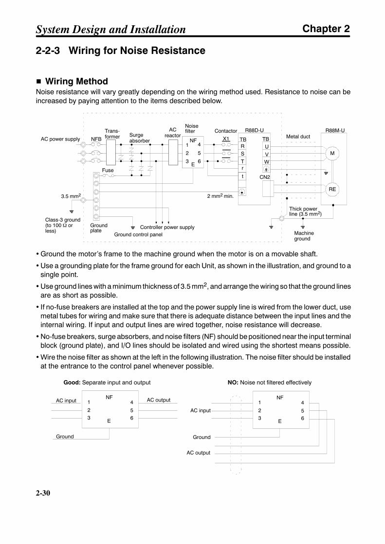
H Wiring MethodNoise resistance will vary greatly depending on the wiring method used. Resistance to noise can beincreased by paying attention to the items described below.
RE
R
T
UVW
CN2
M
NFB
3.5 mm2
R88M-UR88D-U
2 mm2 min.
1
2
3
4NF
E
X1 TB TBAC power supplySurgeabsorber
Noisefilter Contactor
Metal duct
Fuse
Class-3 ground(to 100 Ω orless)
Controller power supply
Thick powerline (3.5 mm2)
Machineground
S5
6
Groundplate
r
t
Ground control panel
Trans-former
ACreactor
• Ground the motor’s frame to the machine ground when the motor is on a movable shaft.
• Use a grounding plate for the frame ground for each Unit, as shown in the illustration, and ground to asingle point.
• Use ground lines with a minimum thickness of 3.5 mm2, and arrange the wiring so that the ground linesare as short as possible.
• If no-fuse breakers are installed at the top and the power supply line is wired from the lower duct, usemetal tubes for wiring and make sure that there is adequate distance between the input lines and theinternal wiring. If input and output lines are wired together, noise resistance will decrease.
• No-fuse breakers, surge absorbers, and noise filters (NF) should be positioned near the input terminalblock (ground plate), and I/O lines should be isolated and wired using the shortest means possible.
• Wire the noise filter as shown at the left in the following illustration. The noise filter should be installedat the entrance to the control panel whenever possible.
Good: Separate input and output NO: Noise not filtered effectively
AC output 1
3
4
6
NF
52
E
1
3
4
6
NF
5
AC input
Ground
AC input
AC output
2
E
Ground
System Design and Installation Chapter 2

2-31
• Use twisted-pair cables for the power supply cables whenever possible, or bind the cables.
Driver
Binding
r
t
or Driver
R
ST
• Separate power supply cables and signal cables when wiring.
H Measures for the EMC DirectivesThis product does not conform to the EMC directives. Wire as shown in the previous Wiring Methodsection diagram to satisfy the EMC directives. The noise filters and transformer are effective for reduc-ing conducted emission and the control box and metal duct are effective for reducing radiated emission.Shielding the motor (while paying attention to the ambient temperature around the motor) is also effec-tive for reducing radiation from the motor. After providing these measures, be sure that the equipmentsatisfies the requirements of the EMC directives.
H Selecting Components
D No-fuse Breakers (MCCB)When selecting no-fuse breakers, take into consideration the maximum input current and the inrushcurrent. The momentary maximum output for a servo system is approximately three times that of therated output, and a maximum output of three seconds can be executed. Therefore, select no-fusebreakers with an operating time of at least five seconds at 300% of the rated maximum output. General-purpose and low-speed no-fuse breakers are generally suitable. Refer to the table in 2-2-2 TerminalBlock Wiring for the power supply input currents for each motor, and then add the current consumptionfor the number of shafts, other controllers, etc., to make the selection.
The Servo Driver inrush current flows at a maximum of 50 A for 20 ms when 200 V is input. With low-speed no-fuse breakers, a inrush current 7 to 8 times the rated current flows for 0.1 second. When mak-ing the selection, take into consideration the entire inrush current for the system.
D Surge AbsorbersUse surge absorbers to absorb surges from power supply input lines due to lightning, abnormal volt-ages, etc. When selecting surge absorbers, take into account the varistor voltage, the amount of surgeimmunity, and the amount of energy resistance. The surge absorbers shown in the following table arerecommended.
Maker Model Varistorvoltage
Max. limitvoltage
Surgeimmunity
Energyresistance
Type
Matsushita ElectricParts
ERZC20EK471(W) 470 V 775 V 5,000 A 150 J BlockMatsushita ElectricParts ERZC25EK471(W) 470 V 775 V 10,000 A 225 J
Block
ERZC32EK471(W) 470 V 775 V 20,000 A 405 JIshizuka Electronics Co. Z25M471S 470 V 810 V 10,000A 235 J BlockIshizuka Electronics Co.
Z33M471S 470 V 810 V 20,000 A 385 J
Block
Note 1. The (W) for the Matsushita models indicates that they are UL and CSA certified.
System Design and Installation Chapter 2
2-32
2-32
Note 2. Refer to manufacturers documentation for operating details.
Note 3. The surge immunity is for a standard impulse current of 8/20 µs. If pulses are wide, either decrease thecurrent or change to a larger-capacity surge absorber.
Note 4. The energy resistance is the value for 2 ms. It may not be possible to retard high-energy pulses at lessthan 700 V. In that case, absorb surges with an insulated transformer or reactor.
D Noise Filters for Power Supply InputUse a noise filter to attenuate extraneous noise and to diminish noise radiation from the Servo Driver.Select a noise filter with a load current of at least twice the rated current. The following table shows noisefilters that reduce by 40 dB noise between 200 kHz and 30 MHz.
Type Model Rated current MakerSingle-phase GT-2050 5 A TokinSingle-phase
ZAC2206-11 6 A TDKLF-315K 15 A TokinLF-325K 25 A
Tokin
LF-335K 35 ALF-380K 80 A
Three-phase ZCW2210-01 10 A TDKThree-phaseZCW2220-01 20 A
TDK
ZCW2230-01 30 AZCW2240-01 40 AZACT2280-ME 80 A
To attenuate noise at frequencies of 200 kHz or less, use an insulated transformer and a noise filter. Forhigh frequencies of 30 MHz or more, use a ferrite core and a high-frequency noise filter with a through-type capacitor.
D Noise Filters for Motor OutputUse noise filters without built-in capacitors on the Servomotor output lines. Output lines cannot use thesame noise filters as the power supply. The following table shows the noise filters that are recom-mended for motor output.
Maker Model Ratedcurrent
Remarks
Tokin LF-310KA 10 A Three-phase block noise filterTokinLF-320KA 20 A
Three-phase block noise filter
LF-350KA 50 A
Note 1. The Servomotor output lines cannot use the same noise filters used for power supplies.
Note 2. Typical noise filters are used with power supply frequencies of 50/60 Hz. If these noise filtersare connected to outputs of 3.3 kHz (the Servo Driver’s PWM frequency), a very large (about100 times larger) leakage current will flow through the noise filter’s condenser and the ServoDriver could be damaged.
System Design and Installation Chapter 2
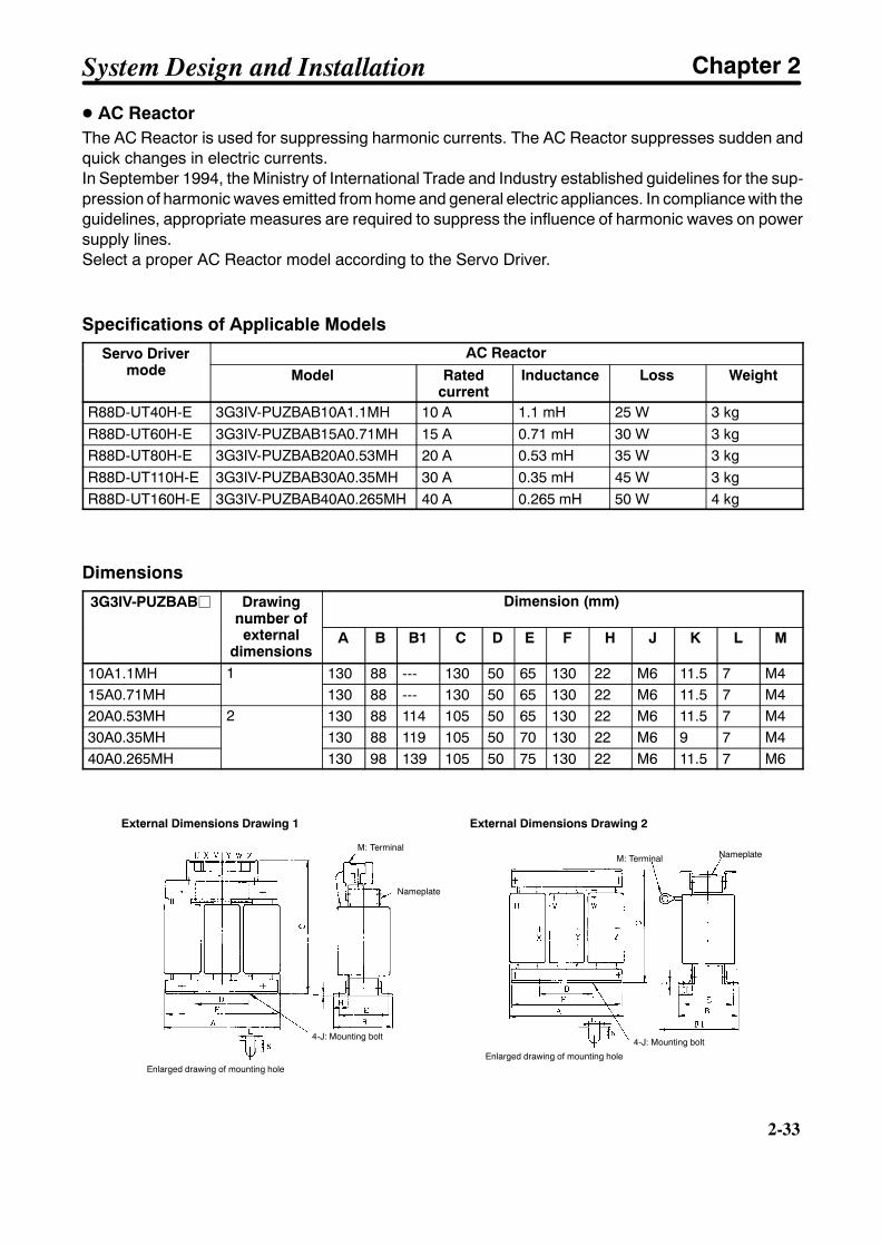
2-33
D AC ReactorThe AC Reactor is used for suppressing harmonic currents. The AC Reactor suppresses sudden andquick changes in electric currents.In September 1994, the Ministry of International Trade and Industry established guidelines for the sup-pression of harmonic waves emitted from home and general electric appliances. In compliance with theguidelines, appropriate measures are required to suppress the influence of harmonic waves on powersupply lines.Select a proper AC Reactor model according to the Servo Driver.
Specifications of Applicable Models
Servo Drivermode
AC ReactorServo Drivermode Model Rated
currentInductance Loss Weight
R88D-UT40H-E 3G3IV-PUZBAB10A1.1MH 10 A 1.1 mH 25 W 3 kgR88D-UT60H-E 3G3IV-PUZBAB15A0.71MH 15 A 0.71 mH 30 W 3 kgR88D-UT80H-E 3G3IV-PUZBAB20A0.53MH 20 A 0.53 mH 35 W 3 kgR88D-UT110H-E 3G3IV-PUZBAB30A0.35MH 30 A 0.35 mH 45 W 3 kgR88D-UT160H-E 3G3IV-PUZBAB40A0.265MH 40 A 0.265 mH 50 W 4 kg
Dimensions
3G3IV-PUZBABj Drawingnumber ofexternal
Dimension (mm)number ofexternal
dimensionsA B B1 C D E F H J K L M
10A1.1MH 1 130 88 --- 130 50 65 130 22 M6 11.5 7 M415A0.71MH
1130 88 --- 130 50 65 130 22 M6 11.5 7 M4
20A0.53MH 2 130 88 114 105 50 65 130 22 M6 11.5 7 M430A0.35MH
2130 88 119 105 50 70 130 22 M6 9 7 M4
40A0.265MH 130 98 139 105 50 75 130 22 M6 11.5 7 M6
External Dimensions Drawing 1
M: Terminal
Nameplate
4-J: Mounting bolt
Enlarged drawing of mounting hole
M: Terminal Nameplate
4-J: Mounting bolt
Enlarged drawing of mounting hole
External Dimensions Drawing 2
System Design and Installation Chapter 2

2-34
2-34
D Surge KillersInstall surge killers for loads that have induction coils, such as relays, solenoids, brakes, clutches, etc.The following table shows types of surge killers and recommended products.
Type Features Recommended productsDiode Diodes are relatively small devices such as relays used
for loads when reset time is not an issue. The reset timeis increased because the surge voltage is the lowestwhen power is cut off. Used for 24/48-VDC systems.
Use a fast-recovery diode with ashort reverse recovery time.
Fuji Electric Co., ERB44-06 or equiv-alent
ThyristororVaristor
Thyristor and varistor are used for loads when inductioncoils are large, as in electromagnetic brakes, solenoids,etc., and when reset time is an issue. The surge voltagewhen power is cut off is approximately 1.5 times that ofthe varistor.
Select varistor voltage as follows:
24-VDC system varistor: 39 V100-VDC system varistor: 200 V100-VAC system varistor: 270 V200-VAC system varistor: 470 V
Capacitor+ resistor
Use capacitors and resistors for vibration absorption ofsurge when power is cut off. The reset time can beshortened by proper selection of the capacitor or resis-tor.
Okaya Electric Ind.
CR-50500 0.5 µF-50 ΩCRE-50500 0.5 µF-50 ΩS2-A-0 0.2 µF-500 Ω
Note Thyristors and varistors are made by the following companies. Refer to manufacturers documentation foroperating details. Thyristors: Ishizuka Electronics Co.
Varistors: Ishizuka Electronics Co., Matsushita Electric Parts
D ContactorsWhen selecting contactors, take into consideration the circuit’s inrush current and the momentary maxi-mum current. The Servo Driver inrush current is 50 A, and the momentary maximum current is approxi-mately twice the rated current. The following table shows the recommended contactors.
Maker Model Rated current Coil voltageLC1D25106 26 ALC1D40116 35 A 200 VACLC1D50116 50 A
200 VAC
OMRON LC1D80116 80 ALP1D25106 26 ALP1D40116 35 A 24 VDCLP1D50116 50 A
24 VDC
LP1D80116 80 A
D Leakage BreakersThe Servomotor is driven by a PWM frequency of 3.3 kHz, so high-frequency current leaks from thearmature. Select leakage breakers designed for inverters. With inverter leakage breakers, high-fre-quency current is not detected, preventing the breaker from operating due to leakage current. Anotherway to prevent leakage current from being detected is to install an insulating transformer.
When selecting leakage breakers, remember to also add the leakage current from devices other thanthe Servomotor, such as machines using a switching power supply, noise filters, inverters, and so on.
System Design and Installation Chapter 2

2-35
Shown below is the leakage current for each servomotor.
Servo Driver Current leakage (includinghigh-frequency current leakage)
checked directly
Current leakage (within the commercialfrequency range) checked using
resistor and capacitorR88D-UT40H-E 50 mA 6 mAR88D-UT60H-ER88D-UT80H-E
70 mA 7 mA
R88D-UT110H-E 90 mA 8 mAR88D-UT160H-E 100 mA 12 mA
Note 1. Each of the current leakage values is rated on condition that the length of the motor powercable is 10 m or less. The current leakage value varies with the length of the motor powercable and the insulator of the motor power cable.
Note 2. The current leakage values are rated at room temperature and humidity.
H Improving Encoder Cable Noise ResistanceSignals from the encoder are either A, B, or S phase. The frequency for A- or B-phase signals is either307.2 kHz (if 3,000-r/min models are used) or 409.6 kHz (if 1,500-r/min models are used), while thetransmission speed for S-phase signals is 1.23 Mbps (if 300-r/min models are used) or 1.64 Mbps (if1,500-r/min models are used). Follow the wiring methods outlined below to improve encoder noiseresistance.
• Be sure to use dedicated encoder cables.
• If lines are interrupted in the middle, be sure to connect them with connectors, making sure that thecable insulation is not peeled off for more than 50 mm. In addition, be sure to use shielded wire.
• Do not coil cables. If cables are long and are coiled, mutual induction and inductance will increase andwill cause malfunctions. Be sure to use cables fully extended.
• When installing noise filters for encoder cables, use clamp cables. The following table shows the rec-ommended clamp filter models.
Maker Name ModelTokin EMI core ESD-QR-25-1TDK Clamp filter ZCAT2032-0930TDK Clamp filter
ZCAT3035-1330ZCAT2035-0930A
• Do not wire the encoder cable in the same duct as power cables and control cables for brakes, sole-noids, clutches, and valves.
H Improving Control I/O Signal Noise ResistancePosition can be affected if control I/O signals are influenced by noise. Follow the methods outlinedbelow for the power supply and wiring.
• Use completely separate power supplies for the control power supply (especially 24 VDC) and theexternal operation power supply. In particular, be careful not to connect two power supply groundwires. Install a noise filter on the primary side of the control power supply.
• As much as possible, keep the power supply for pulse command and error counter reset input linesseparate from the control power supply. Be particularly careful not to connect the two power supplyground lines.
System Design and Installation Chapter 2

2-36
2-36
• It is recommended that a line driver be used for pulse command and error counter reset outputs.
• Be sure to use twisted-pair shielded wire for pulse command and error counter reset signal lines, andconnect both ends of the wires to frame grounds.
• For speed and torque command input lines, be sure to use twisted-pair shielded cable, and connectboth ends of the shield wire to ground.
• If the control power supply wiring is long, noise resistance can be improved by adding 1-µF laminatedceramic capacitors between the control power supply and ground at the Servo Driver input sectionand the controller output section.
• For encoder output (A, B, and Z phase) lines, be sure to use twisted-pair shielded cable, and connectboth ends of the shield wire to ground.
• For open collector specifications, keep the length of wires to within one meter.
System Design and Installation Chapter 2

2-37
2-2-4 Peripheral Device Connection Examples
r
U
V
W
CN2
1
4
3
6NFE
NFB
B
1MC
XB
E
X
M
ON
1MC X
CN1
24 VDC32 ALMCOM
BKIR 27
OGND 28
XB
OFF
CN1
31 ALM
24 VDC
24VDC
R T
CN1
Noise filter
Class-3 ground
Main-circuitpower supply Main-circuit connector
Surge killer
OMNUC U-seriesAC Servo Driver
OMNUC U-seriesAC Servomotor
Class-3 ground
Use
r’sco
ntro
ldev
ice
R88A-CRUBjjjCEncoder CableX
1MC
2
S
5
t
R
S
T
Three-phase, 200/230 VAC, 50/60 Hz
(Note: Set by user parameter Cn-2d.)
P1
BRegenerativeresistance
(Note: For ServoDrivers with 5.5kW min. only.)
AC reactor
P1
B
Power CableR88A-CAUBjjjS/-CAUCjjjS(-CAUBjjjB/-CAUCjjjB)
Regenerative ResistorR88A-RR22047SRegenerative Resistor can only be externallyattached for the R88D-UT160H-E.
Thermalswitch contact
System Design and Installation Chapter 2
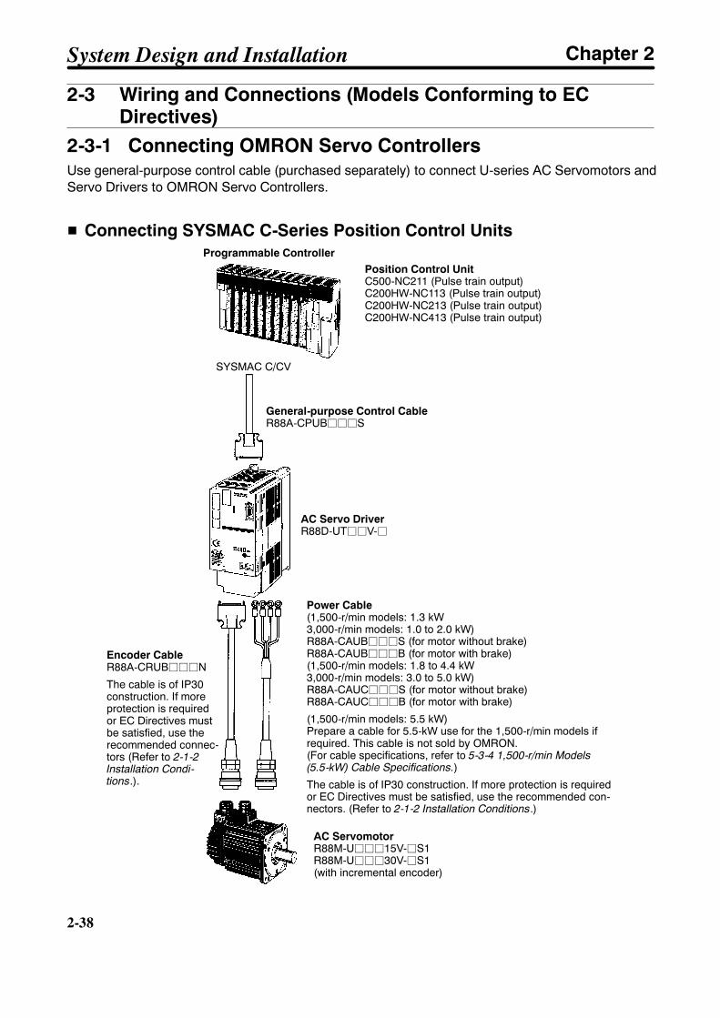
2-38
2-38
2-3 Wiring and Connections (Models Conforming to ECDirectives)
2-3-1 Connecting OMRON Servo ControllersUse general-purpose control cable (purchased separately) to connect U-series AC Servomotors andServo Drivers to OMRON Servo Controllers.
H Connecting SYSMAC C-Series Position Control UnitsProgrammable Controller
Position Control UnitC500-NC211 (Pulse train output)C200HW-NC113 (Pulse train output)C200HW-NC213 (Pulse train output)C200HW-NC413 (Pulse train output)
General-purpose Control CableR88A-CPUBjjjS
Power Cable(1,500-r/min models: 1.3 kW3,000-r/min models: 1.0 to 2.0 kW)R88A-CAUBjjjS (for motor without brake)R88A-CAUBjjjB (for motor with brake)(1,500-r/min models: 1.8 to 4.4 kW3,000-r/min models: 3.0 to 5.0 kW)R88A-CAUCjjjS (for motor without brake)R88A-CAUCjjjB (for motor with brake)
(1,500-r/min models: 5.5 kW)Prepare a cable for 5.5-kW use for the 1,500-r/min models ifrequired. This cable is not sold by OMRON.(For cable specifications, refer to 5-3-4 1,500-r/min Models(5.5-kW) Cable Specifications.)
The cable is of IP30 construction. If more protection is requiredor EC Directives must be satisfied, use the recommended con-nectors. (Refer to 2-1-2 Installation Conditions.)
Encoder CableR88A-CRUBjjjN
The cable is of IP30construction. If moreprotection is requiredor EC Directives mustbe satisfied, use therecommended connec-tors (Refer to 2-1-2Installation Condi-tions.).
AC Servo DriverR88D-UTjjV-j
SYSMAC C/CV
AC ServomotorR88M-Ujjj15V-jS1R88M-Ujjj30V-jS1(with incremental encoder)
System Design and Installation Chapter 2

2-39
H Connecting to SYSMAC C/CV-series Motion Control Units
Programmable Controller
Motion Control UnitCV500-MC221 (Analog output)CV500-MC421-EV1 (Analog output)C200H-MC221 (Analog output)
General-purpose Control CableR88A-CPUBjjjM1 (for single axis)R88A-CPUBjjjM2 (for double axis)
Power Cable(1,500-r/min models: 1.3 kW3,000-r/min models: 1.0 to 2.0 kW)R88A-CAUBjjjS (for motor without brake)R88A-CAUBjjjB (for motor with brake)(1,500-r/min models: 1.8 to 4.4 kW3,000-r/min models: 3.0 to 5.0 kW)R88A-CAUCjjjS (for motor without brake)R88A-CAUCjjjB (for motor with brake)
(1,500-r/min models: 5.5 kW)Prepare a cable for 5.5-kW use for the 1,500-r/minmodels if required. This cable is not sold by OMRON.(For cable specifications, refer to 5-3-4 1,500-r/minModels (5.5-kW) Cable Specifications.)
The cable is of IP30 construction. If more protectionis required or EC Directives must be satisfied, usethe recommended connectors. (Refer to 2-1-2 Instal-lation Conditions.)
AC Servo DriverR88D-UTjjV-j
SYSMAC C/CV
Encoder CableR88A-CRUBjjjN(for both incremental and absolute encoders)
The cable is of IP30 construction. If moreprotection is required or EC Directives mustbe satisfied, use the recommended connec-tors (Refer to 2-1-2 Installation Conditions.).
Back-up BatteryTo be connected whenusing a motor with anabsolute encoder
AC ServomotorR88M-Ujjj15X-jS1R88M-Ujjj30X-jS1(with absolute encoder)
AC ServomotorR88M-Ujjj15V-jS1R88M-Ujjj30V-jS1(with incremental encoder)
Note Refer to Chapter 5 Specifications for connector and cable specifications.
System Design and Installation Chapter 2

2-40
2-40
2-3-2 Wiring Servo DriversProvide proper wire diameters, ground systems, and noise resistance when wiring terminal blocks.
H Wiring Terminal Blocks• R88D-UT24V-j/UT40V-j/UT60V-j/UT80V-j
Power Cable(1,500-r/min models: 1.3 kW3,000-r/min models: 1.5 to 2.0 kW)R88A-CAUBjjjS (for motor without brake)R88A-CAUBjjjB (for motor with brake)(1,500-r/min models: 1.8 to 4.4 kW3,000-r/min models: 3.0 to 5.0 kW)R88A-CAUCjjjS (for motor without brake)R88A-CAUCjjjB (for motor with brake)(1,500-r/min models: 5.5 kW)Prepare a cable for 5.5-kW use for the1,500-r/min models if required. This cable is notsold by OMRON.
The cable is of IP30 construction. If more protec-tion is required or EC Directives must be satis-fied, use the recommended connectors. (Refer to2-1-2 Installation Conditions.)
Control Circuit Power SupplySingle-phase 200/230 VAC50/60 Hz
Signal line for brake 24 VDC ±10%No polarity
Class-3 ground min. Main Circuit Power SupplyThree-phase 200/230 VAC50/60 Hz
Red White Black Green
Brown
Yellow
R S T
L1
L1C L3C --
L2 L3 + B
System Design and Installation Chapter 2

2-41
• R88D-UT110V/UT160V-E
Control Circuit Power SupplySingle-phase 200/230 VAC50/60 Hz
Main Circuit Power SupplyThree-phase 200/230 VAC50/60 Hz
Class-3 ground min.
Signal line for brake
24 VDC ±10%No polarity
Power Cable
R88A-CAUCjjjS (for motorwithout brake)R88A-CAUCjjjB (for motorwith brake)
The cable is of IP30 construc-tion. If more protection isrequired or to conform to the ECDirectives, use the recom-mended connectors. Refer to2-1-2 Installation Conditions.
Green
Red White Black
Brown
Yellow
System Design and Installation Chapter 2
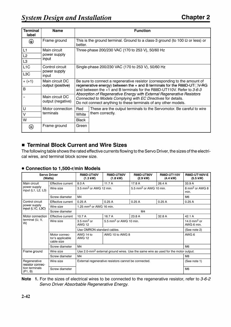
2-42
2-42
Terminallabel
Name Function
Frame ground This is the ground terminal. Ground to a class-3 ground (to 100 Ω or less) orbetter.
L1 Main circuitpower supply
Three-phase 200/230 VAC (170 to 253 V), 50/60 HzL2
Main circuitpower supplyinput
Three-phase 200/230 VAC (170 to 253 V), 50/60 Hz
L3input
L1C Control circuitpower supply
Single-phase 200/230 VAC (170 to 253 V), 50/60 Hz
L3Cpower supplyinput
+ (+1) Main circuit DCoutput (positive)
Be sure to connect a regenerative resistor (corresponding to the amount ofregenerative energy) between the + and B terminals for the R88D-UTjV-RG
Boutput (positive) regenerative energy) between the + and B terminals for the R88D-UTjV-RG
and between the +1 and B terminals for the R88D-UT110V. Refer to 3-6-3Absorption of Regenerative Energy with External Regenerative Resistors
-- Main circuit DCoutput (negative)
Absorption of Regenerative Energy with External Regenerative ResistorsConnected to Models Complying with EC Directives for details.Do not connect anything to these terminals of any other models.
U Motor connectionterminals
Red These are the output terminals to the Servomotor. Be careful to wirethem correctly.V
Motor connectionterminals White
These are the output terminals to the Servomotor. Be careful to wirethem correctly.
W BlackFrame ground Green
H Terminal Block Current and Wire SizesThe following table shows the rated effective currents flowing to the Servo Driver, the sizes of the electri-cal wires, and terminal block screw size.
D Connection to 1,500-r/min ModelsServo Driver
(Watts)R88D-UT40V
(1.3 kW)R88D-UT60V
(1.8 kW)R88D-UT80V
(2.9 kW)R88D-UT110V
(4.4 kW)R88D-UT160V-E
(5.5 kW)
Main circuitpower supply
Effective current 8.0 A 11.7 A 17.8 A 26.4 A 33.9 AMain circuitpower supplyinput (L1, L2, L3)
Wire size 3.5 mm2 or AWG 12 min. 5.5 mm2 or AWG 10 min. 8 mm2 or AWG 8min.
Screw diameter M4 M6Control circuitpower supply
Effective current 0.25 A 0.25 A 0.25 A 0.25 A 0.25 AControl circuitpower supplyinput (L1C, L3C)
Wire size 1.25 mm2 or AWG 16 min.input (L1C, L3C)
Screw diameter M4Motor connectionterminal (U, V,
Effective current 10.7 A 16.7 A 23.8 A 32.8 A 42.1 AMotor connectionterminal (U, V,W)
Wire size 3.5 mm2 orAWG 12
5.5 mm2 or AWG 10 min. 14.0 mm2 orAWG 6 min.
Use OMRON standard cables. (See note 2)
Motor connec-tor’s applicablecable size
AWG 14 toAWG 12
AWG 10 to AWG 8 AWG 6
Screw diameter M4 M6
Frame ground Wire size Use 2.0-mm2 external ground wires. Use the same wire as used for the motor output.Frame ground
Screw diameter M4 M8
Regenerativeresistor connec-tion terminals
Wire size External regenerative resistors cannot be connected. (See note 1)resistor connec-tion terminals(P1, B)
Screw diameter M6
Note 1. For the sizes of electrical wires to be connected to the regenerative resistor, refer to 3-6-2Servo Driver Absorbable Regenerative Energy.
System Design and Installation Chapter 2

2-43
Note 2. Prepare a 5.5-kw cable for the 1,500-r/min models if required. This cable is not sold byOMRON.
D Connection to 3,000-r/min ModelsServo Driver
(Watts)R88D-UT24V
(1.0 kW)R88D-UT40V
(1.5 kW)R88D-UT60V
(2.0 kW)R88D-UT80V
(3.0 kW)R88D-UT110VServo Driver
(Watts)R88D-UT24V
(1.0 kW)R88D-UT40V
(1.5 kW)R88D-UT60V
(2.0 kW)R88D-UT80V
(3.0 kW) (4.0kW)
(5.0kW)
Main circuit powersupply input (L1, L2,
Effective current 6.6 A 9.2 A 13.0 A 18.4 A 24.0 A 28.0 Asupply input (L1, L2,L3) Wire size 3.5 mm2 or AWG 12 min. 5.5 mm2 or AWG 10 min.
Control circuit powersupply input (L1C,
Effective current 0.25 A 0.25 A 0.25 A 0.25 A 0.25 A 0.25 Asupply input (L1C,L3C) Wire size 1.25 mm2 or AWG 16 min.
Motor connection ter-minal (U, V, W)
Effective current 6.1 A 9.9 A 12.0 A 19.4 A 25.3 A 26.2 AMotor connection ter-minal (U, V, W) Wire size 3.5 mm2 or AWG 12 5.5 mm2 or AWG 10 min.Wire size
Use OMRON standard cables.
Motor connector’sapplicable cable size
AWG 14 to AWG 12 AWG 10 to AWG 8
Frame ground Wire size Use 2.0-mm2 external ground wires. Use the same wire as used for the motor output.
Terminal block screw size M4
H Wire Sizes and Allowable CurrentThe following table shows allowable currents when there are three electrical wires. Use values equal toor lower than the specified values.
D 600-V Heat-resistant Vinyl Wiring (HIV) (Reference Values)AWG size Nominal cross-
sectional area(mm2)
Configuration(wires/mm2)
Conductiveresistance
(Ω/km)
Allowable current (A) forambient temperaturesectional area
(mm2)(wires/mm ) resistance
(Ω/km) 30°C 40°C 50°C16 1.25 7/0.45 17.5 16 14 1114 2.0 7/0.6 9.53 23 20 1612 3.5 7/0.8 5.41 33 29 2410 5.5 7/1.0 3.47 43 38 318 8.0 7/1.2 2.41 55 49 406 14.0 7/1.6 1.35 79 70 57
2-3-3 Wiring Conditions Satisfying EMC DirectivesModels complying with EC Directives must abide by the following wiring conditions to satisfy EMCDirective EN55011 (EMI) Class A, group I and EN50082-2 requirements (EMS).If the models cannot abide by the conditions because the models are built into equipment, the equip-ment must be completely examined to make sure that the equipment satisfies EC Directives.
S The Servo Driver must be mounted to a metal panel (i.e., a control panel).
S The power supply line must be connected to a noise filter and a surge absorber to protect thepower supply lines from lightning or any other surge.
S The I/O signal and encoder signal lines must be constructed of cables with braided shield wiremade of tin-coated annealed copper.
System Design and Installation Chapter 2
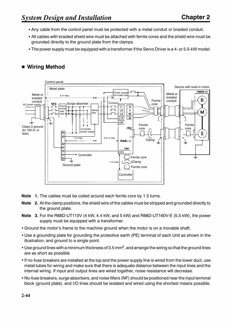
2-44
2-44
S Any cable from the control panel must be protected with a metal conduit or braided conduit.
S All cables with braided shield wire must be attached with ferrite cores and the shield wire must begrounded directly to the ground plate from the clamps.
S The power supply must be equipped with a transformer if the Servo Driver is a 4- or 5.5-kW model.
H Wiring Method
Control panel
Trans-former(seenote 3)
Metal plate
Contactor
Power supplyfor brake use
Device with built-in motor
Ferrite core
Ferrite core
Noisefilter
Controllerpower supply
Controller
Ground plate
Class-3 ground(to 100 Ω. orless)
AC power supply Surge absorber
Metal orbraidedconduit
Clamp
Controller
Clamp
Ferritecore
Ferritecore
Metal orbraidedconduit Ferrite
core
0.5 m max.
1 m max. 0.5 m max.
1 m max.
2 m max.
Note 1. The cables must be coiled around each ferrite core by 1.5 turns.
Note 2. At the clamp positions, the shield wire of the cables must be stripped and grounded directly tothe ground plate.
Note 3. For the R88D-UT110V (4 kW, 4.4 kW, and 5 kW) and R88D-UT160V-E (5.5 kW), the powersupply must be equipped with a transformer.
• Ground the motor’s frame to the machine ground when the motor is on a movable shaft.
• Use a grounding plate for grounding the protective earth (PE) terminal of each Unit as shown in theillustration, and ground to a single point.
• Use ground lines with a minimum thickness of 3.5 mm2, and arrange the wiring so that the ground linesare as short as possible.
• If no-fuse breakers are installed at the top and the power supply line is wired from the lower duct, usemetal tubes for wiring and make sure that there is adequate distance between the input lines and theinternal wiring. If input and output lines are wired together, noise resistance will decrease.
• No-fuse breakers, surge absorbers, and noise filters (NF) should be positioned near the input terminalblock (ground plate), and I/O lines should be isolated and wired using the shortest means possible.
System Design and Installation Chapter 2
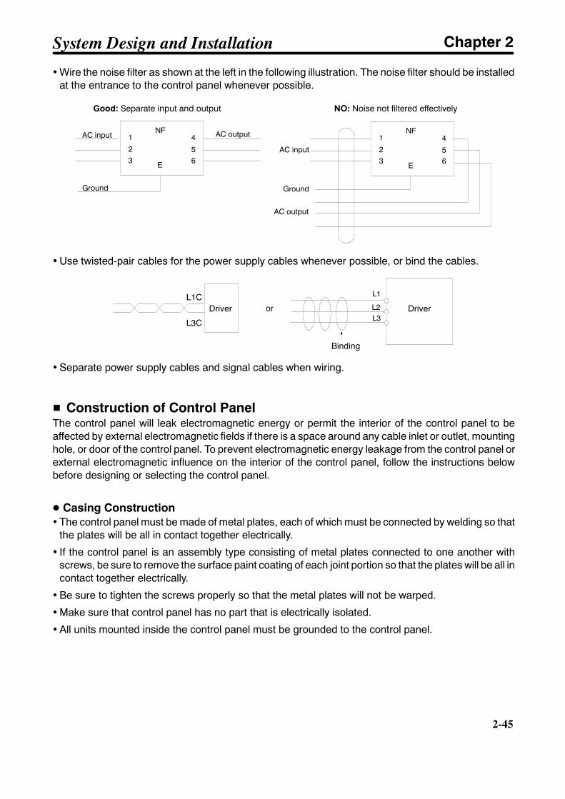
2-45
• Wire the noise filter as shown at the left in the following illustration. The noise filter should be installedat the entrance to the control panel whenever possible.
Good: Separate input and output NO: Noise not filtered effectively
AC output 1
3
4
6
NF
52
E
1
3
4
6
NF
5
AC input
Ground
AC input
AC output
2
E
Ground
• Use twisted-pair cables for the power supply cables whenever possible, or bind the cables.
Driver
Binding
L1C
L3C
or Driver
L1
L2L3
• Separate power supply cables and signal cables when wiring.
H Construction of Control PanelThe control panel will leak electromagnetic energy or permit the interior of the control panel to beaffected by external electromagnetic fields if there is a space around any cable inlet or outlet, mountinghole, or door of the control panel. To prevent electromagnetic energy leakage from the control panel orexternal electromagnetic influence on the interior of the control panel, follow the instructions belowbefore designing or selecting the control panel.
D Casing Construction• The control panel must be made of metal plates, each of which must be connected by welding so that
the plates will be all in contact together electrically.
• If the control panel is an assembly type consisting of metal plates connected to one another withscrews, be sure to remove the surface paint coating of each joint portion so that the plates will be all incontact together electrically.
• Be sure to tighten the screws properly so that the metal plates will not be warped.
• Make sure that control panel has no part that is electrically isolated.
• All units mounted inside the control panel must be grounded to the control panel.
System Design and Installation Chapter 2

2-46
2-46
D Door Construction• The door must be made of metal.
• The space between the door and casing must be of watertight construction as shown below.
• Apply conductive packing to the space between the casing and door as shown below.Be sure to remove the surface paint coating of the portion of the casing and that of the door coming intocontact with the conductive packing so that the door, conductive packing, and casing will be all in con-tact electrically.
• Be sure to tighten the screws properly so that the metal plates of the control panel will not be warped.
Door
Control panel
Oil-proof packing
Conductive packing
Door (inner side)
Casing side
Oil-proof packing Conductive packing
Door side
A-B Cross-section
Casing
H Selecting ComponentsThis section describes standards to be considered when selecting components to be connected toreduce noise. Select components after reviewing characteristics such as capacities, performance, andapplication ranges. Recommended components are listed below for reference. For further details, con-sult the respective manufacturer.
System Design and Installation Chapter 2

2-47
D No-fuse Breakers (MCCB)When selecting no-fuse breakers, take into consideration the maximum input current and the inrushcurrent. The momentary maximum output for a servo system is approximately three times that of therated output, and a maximum output of three seconds can be executed. Therefore, select no-fusebreakers with an operating time of at least five seconds at 300% of the rated maximum output. General-purpose and low-speed no-fuse breakers are generally suitable. Refer to the table in 2-2-2 TerminalBlock Wiring for the power supply input currents for each motor, and then add the current consumptionfor the number of shafts, other controllers, etc., to make the selection.
The Servo Driver inrush current flows at a maximum of 50 A for 20 ms when 200 V is input. With low-speed no-fuse breakers, a inrush current 7 to 8 times the rated current flows for 0.1 second. When mak-ing the selection, take into consideration the entire inrush current for the system.
D Surge AbsorbersUse surge absorbers to absorb surges from power supply input lines due to lightning, abnormal volt-ages, etc. When selecting surge absorbers, take into account the varistor voltage, the amount of surgeimmunity, and the amount of energy resistance. For the 200-VAC series, use one with varistor voltage of470 V. The surge absorbers shown in the following table are recommended.
Maker Model Max. limitvoltage
Surge immunity Type Remarks
Okaya ElectricInd.
R.A.V-781BYZ-2 783 V 1,000 A Block Between powerlinesInd.
R.A.V-781BXZ-4 783 V 1,000 A Between thepower line andgrounding
Note 1. Refer to manufacturers documentation for operating details.
Note 2. The surge immunity is for a standard impulse current of 8/20 µs. If pulses are wide, either decrease thecurrent or change to a larger-capacity surge absorber.
D Noise FiltersApply the following Schaffner noise filter to the power supply for the Servo Driver.
Application Model Ratedcurrent (at
40_C)
Ratedvoltage
Test voltage Leakagecurrent (at400V, 50 Hz
max.)(See note)
1.0 to 1.5 kW FN351-16/29 16 A 440 V 2,250 VDC for 2 seconds(between terminal and
17.5 mA
1.8 to 2.0 kW FN351-25/29 25 A (between terminal andcase) 160 mA
2.9 to 3.0 kW FN351-36/33 36 Acase)
1,100 VDC for 2 seconds 160 mA
4.0 to 5.0 kW FN351-50/33 50 A1,100 VDC for 2 seconds(between terminals) 175 mA
5.5 kW FN258-75/34 75 A 480 V 2,250 VDC for 2 seconds(between terminal andcase)
1,700 VDC for 2 seconds(between terminals)
113 mA
Note The leakage current values shown in the table indicate those for star-connection (Y-connection)three-phase power supply. For the delta-connection (∆-connection) power supply, the valuesmay become larger than those shown in the table.
System Design and Installation Chapter 2
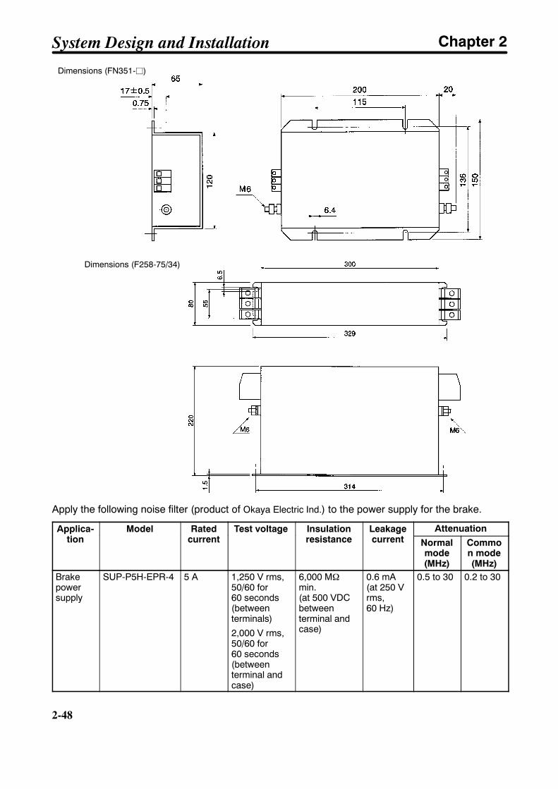
2-48
2-48
Dimensions (FN351-j)
Dimensions (F258-75/34)
Apply the following noise filter (product of Okaya Electric Ind.) to the power supply for the brake.
Applica-tion
Model Ratedcurrent
Test voltage Insulationresistance
Leakagecurrent
AttenuationApplica-tion
Model Ratedcurrent
Test voltage Insulationresistance
Leakagecurrent Normal
mode(MHz)
Common mode(MHz)
Brakepowersupply
SUP-P5H-EPR-4 5 A 1,250 V rms,50/60 for60 seconds(betweenterminals)
2,000 V rms,50/60 for60 seconds(betweenterminal andcase)
6,000 MΩmin.(at 500 VDCbetweenterminal andcase)
0.6 mA(at 250 Vrms,60 Hz)
0.5 to 30 0.2 to 30
System Design and Installation Chapter 2
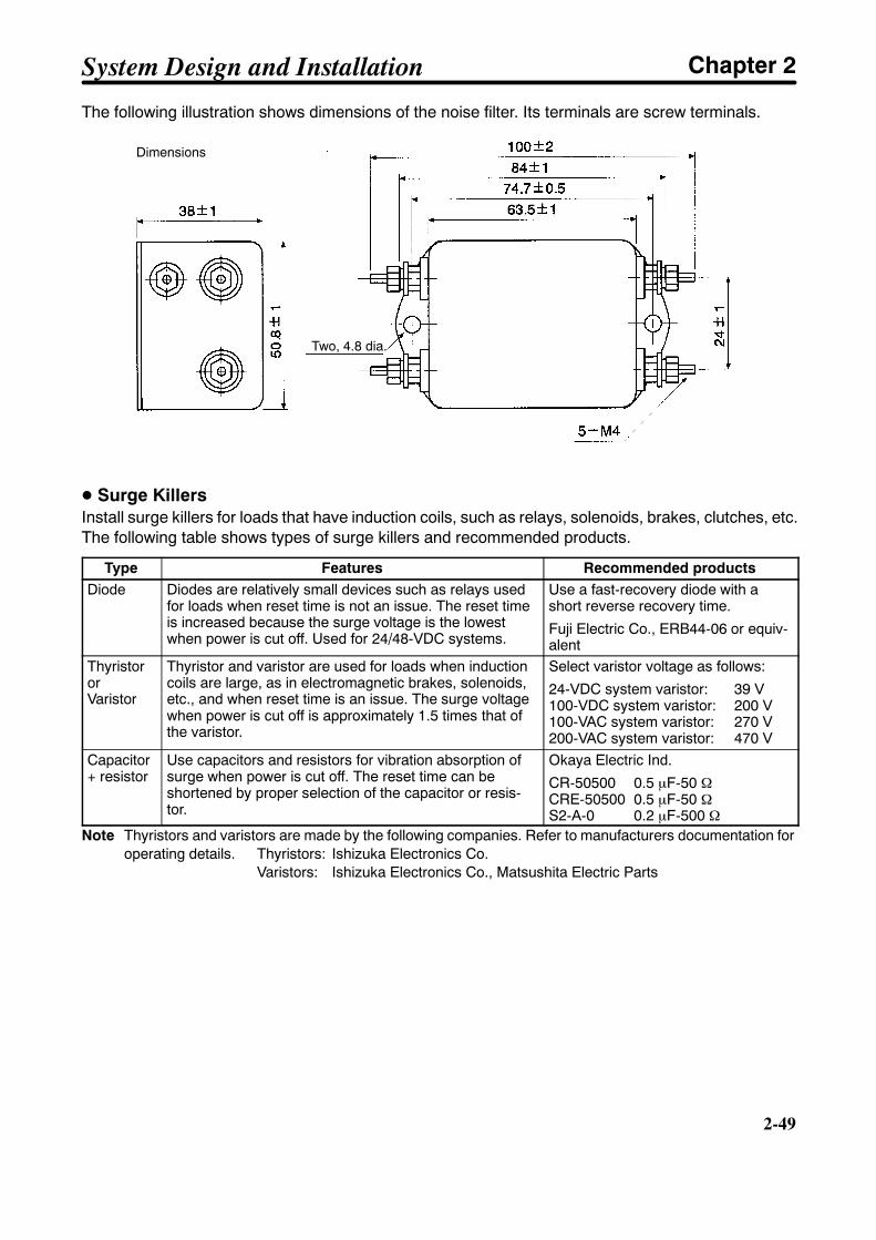
2-49
The following illustration shows dimensions of the noise filter. Its terminals are screw terminals.
Dimensions
Two, 4.8 dia.
D Surge KillersInstall surge killers for loads that have induction coils, such as relays, solenoids, brakes, clutches, etc.The following table shows types of surge killers and recommended products.
Type Features Recommended productsDiode Diodes are relatively small devices such as relays used
for loads when reset time is not an issue. The reset timeis increased because the surge voltage is the lowestwhen power is cut off. Used for 24/48-VDC systems.
Use a fast-recovery diode with ashort reverse recovery time.
Fuji Electric Co., ERB44-06 or equiv-alent
ThyristororVaristor
Thyristor and varistor are used for loads when inductioncoils are large, as in electromagnetic brakes, solenoids,etc., and when reset time is an issue. The surge voltagewhen power is cut off is approximately 1.5 times that ofthe varistor.
Select varistor voltage as follows:
24-VDC system varistor: 39 V100-VDC system varistor: 200 V100-VAC system varistor: 270 V200-VAC system varistor: 470 V
Capacitor+ resistor
Use capacitors and resistors for vibration absorption ofsurge when power is cut off. The reset time can beshortened by proper selection of the capacitor or resis-tor.
Okaya Electric Ind.
CR-50500 0.5 µF-50 ΩCRE-50500 0.5 µF-50 ΩS2-A-0 0.2 µF-500 Ω
Note Thyristors and varistors are made by the following companies. Refer to manufacturers documentation foroperating details. Thyristors: Ishizuka Electronics Co.
Varistors: Ishizuka Electronics Co., Matsushita Electric Parts
System Design and Installation Chapter 2

2-50
2-50
D ContactorsWhen selecting contactors, take into consideration the circuit’s inrush current and the momentary maxi-mum current. The Servo Driver inrush current is 50 A, and the momentary maximum current is approxi-mately twice the rated current. The following table shows the recommended contactors.
Maker Model Rated current Coil voltageLC1D25106 26 ALC1D40116 35 A 200 VACLC1D50116 50 A
200 VAC
OMRON LC1D80116 80 ALP1D25106 26 ALP1D40116 35 A 24 VDCLP1D50116 50 A
24 VDC
LP1D80116 80 A
D Leakage BreakersSelect leakage breakers designed for inverters.Since switching takes place inside the Servo Drivers, high-frequency current leaks from the armature ofthe motor.With inverter leakage breakers, high-frequency current is not detected, preventing the breaker fromoperating due to leakage current.
When selecting leakage breakers, remember to also add the leakage current from devices other thanthe Servomotor, such as machines using a switching power supply, noise filters, inverters, and so on.When selecting leakage breakers, refer to the manufacturer’s catalog.
The following table shows leakage current of each Servomotor.
Driver Leakage current (directmeasurement)
(including high-frequencycurrent)
Leakage current(resistor/capacitor
measurement)(commercial power supply
frequency range)R88D-UT24V-jR88D-UT40V-j
50 mA 6 mA
R88D-UT60V-jR88D-UT80V-j
70 mA 7 mA
R88D-UT110V 100 mA 12 mAR88D-UT160V-E
100 mA 12 mA
Note 1. The above leakage current is for cases where motor power line length is less than 10 m. (Itvaries depending on the power line length and insulation.)
Note 2. The above leakage current is for normal temperature and humidity. (It varies depending onthe temperature and humidity.)
H Improving Encoder Cable Noise ResistanceSignals from the encoder are either A, B, or S phase (Z phase). The frequency for A- or B-phase signalsis either 307.2 kHz (if an incremental encoder is used) or 614.4 kHz (if an absolute encoder is used),while the transmission speed for S-phase signals is 1.23 Mbps. Follow the wiring methods outlinedbelow to improve encoder noise resistance.
• Be sure to use dedicated encoder cables.
System Design and Installation Chapter 2

2-51
• If lines are interrupted in the middle, be sure to connect them with connectors, making sure that thecable insulation is not peeled off for more than 50 mm. In addition, be sure to use shielded wire.
• Do not coil cables. If cables are long and are coiled, mutual induction and inductance will increase andwill cause malfunctions. Be sure to use cables fully extended.
• When installing noise filters for encoder cables, use clamp cables. The following table shows the rec-ommended clamp filter models.
Maker Name ModelTokin EMI core ESD-QR-25-1TDK Clamp filter ZCAT2032-0930TDK Clamp filter
ZCAT3035-1330ZCAT2035-0930A
• Do not wire the encoder cable in the same duct as power cables and control cables for brakes, sole-noids, clutches, and valves.
H Improving Control I/O Signal Noise ResistancePosition can be affected if control I/O signals are influenced by noise. Follow the methods outlinedbelow for the power supply and wiring.
• Use completely separate power supplies for the control power supply (especially 24 VDC) and theexternal operation power supply. In particular, be careful not to connect two power supply groundwires. Install a noise filter on the primary side of the control power supply.
• As much as possible, keep the power supply for pulse command and deviation counter reset inputlines separate from the control power supply. Be particularly careful not to connect the two power sup-ply ground lines.
• It is recommended that a line driver be used for pulse command and deviation counter reset outputs.
• Be sure to use twisted-pair shielded wire for pulse command and deviation counter reset signal lines,and connect both ends of the wires to frame grounds.
• For speed and torque command input lines, be sure to use twisted-pair shielded cable, and connectboth ends of the shield wire to ground.
• If the control power supply wiring is long, noise resistance can be improved by adding 1-µF laminatedceramic capacitors between the control power supply and ground at the Servo Driver input sectionand the controller output section.
• For encoder output (A, B, and Z phase) lines, be sure to use twisted-pair shielded cable, and connectboth ends of the shield wire to ground.
• For open collector specifications, keep the length of wires to within one meter.
System Design and Installation Chapter 2
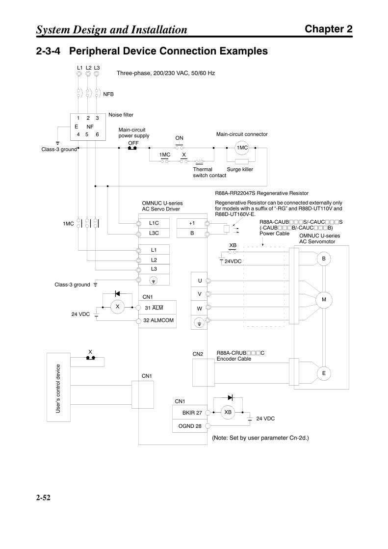
2-52
2-52
2-3-4 Peripheral Device Connection Examples
L1C
U
V
W
CN2
1
4
3
6NFE
NFB
B
1MC
XB
E
XM
ON
1MC X
CN1
24 VDC32 ALMCOM
BKIR 27
OGND 28
XB
OFF
CN1
31 ALM
24 VDC
24VDC
L1 L3
CN1
Noise filter
Class-3 ground
Main-circuitpower supply Main-circuit connector
Surge killer
OMNUC U-seriesAC Servo Driver
OMNUC U-seriesAC Servomotor
Class-3 ground
Use
r’sco
ntro
ldev
ice
R88A-CRUBjjjCEncoder Cable
X
1MC
2
L2
5
L3C
L1
L2
L3
Three-phase, 200/230 VAC, 50/60 Hz
(Note: Set by user parameter Cn-2d.)
R88A-CAUBjjjS/-CAUCjjjS(-CAUBjjjB/-CAUCjjjB)Power Cable
R88A-RR22047S Regenerative Resistor
Regenerative Resistor can be connected externally onlyfor models with a suffix of “-RG” and R88D-UT110V andR88D-UT160V-E.
+1
B
Thermalswitch contact
System Design and Installation Chapter 2
Chapter 3
Operation3-1 Beginning Operation
3-2 System Check Mode (Cn-00)3-3 Function Settings
3-4 Trial Operation
3-5 Making Adjustments3-6 Regenerative Energy Absorption
3

!
!
!
!
!
!
3-2
3-2
Operation and Adjustment PrecautionsCaution Check the newly set parameters for proper execution before actually running them.
Not doing so may result in equipment damage.
Caution Do not make any extreme adjustments or setting changes. Doing so may result inunstable operation and injury.
Caution Separate the Servomotor from the machine, check for proper operation, and thenconnect to the machine. Not doing so may cause injury.
Caution When an alarm occurs, remove the cause, reset the alarm after confirming safety,and then resume operation. Not doing so may result in injury.
Caution Do not come close to the machine immediately after resetting momentary powerinterruption to avoid an unexpected restart. (Take appropriate measures to securesafety against an unexpected restart.) Doing so may result in injury.
Caution Do not use the built-in brake of the Servomotor for ordinary braking. Doing so mayresult in malfunction.
Operation Chapter 3
3-3
3-1 Beginning Operation
3-1-1 Operational Procedure
Before beginning operation, be sure to make the initial settings for the Servo Driver.Make function settings as required according to the use of the Servomotor.
H Startup Procedure1. Mounting and installation
Install the Servomotor and Servo Driver according to the installation conditions: Chapter 2, section2-1.
2. Wiring and connections
Connect to power supply and peripheral devices: Chapter 2, section 2-2.
3. Turning on power supply
Before turning on the power supply, check the necessary items. In order to make the initial settings,turn on an application power supply: Chapter 3, section 3-1-2.
4. Checking display status
Check by means of the displays to see whether there are any internal errors in the Servo Driver:Chapter 3, section 3-1-2
5. Initial settings
Make the settings for the operation setup parameters (initial settings): Chapter 3, section 3-3-1.
6. Function settings
By means of the user parameters, set the functions according to the operating conditions: Chapter3, section 3-3-2.
7. Trial operation
Check to see whether protective functions such as emergency stop and operational limits are work-ing reliably. Check operation at both low speed and high speed: Chapter 3, section 3-4.
8. Adjustments
Execute auto-tuning. Manually adjust the gain as required: Chapter 3, section 3-5.
9. Operation
Operation can now begin. If any trouble should occur, refer to Chapter 4 Application: Chapter 4.
Operation Chapter 3
3-4
3-4
3-1-2 Turning On Power and Checking Displays
H Items to Check Before Turning On Power
D Checking Power Supply Voltage• Check to be sure that the power supply voltage is within the ranges shown below.
Main-circuit power supply: Three-phase 200/230 VAC (170 to 253 V) 50/60 Hz
Control-circuit power supply: Single-phase 200/230 VAC (170 to 253 V) 50/60 Hz
D Checking Terminal Block Wiring• The main-circuit power supply inputs (R, S, and T or L1, L2, and L3) and the control-circuit power
supply inputs (r and t or L1C and L2C) must be properly connected to the terminal block.
• The Servomotor’s red (U), white (V), and black (W) power lines and the green ground wire ( ) mustbe properly connected to the terminal block.
D Checking the Servomotor• There should be no load on the Servomotor. (Do not connect to the mechanical system.)
• The power line connectors at the Servomotor must be securely connected.
D Checking the Encoder Connectors• The encoder connectors (CN2) at the Servo Driver must be securely connected.
• The encoder connectors at the Servomotor must be securely connected.
D Checking the Control Connectors• The control connectors must be securely connected.
• The operation command (RUN) must be OFF.
D Checking Parameter Unit Connections• The Parameter Unit (R88A-PR02U or R88A-PR03U) must be securely connected to the CN3 con-
nector.
H Turning On Power• First carry out the preliminary checks, and then turn on the control-circuit power supply. It makes no
difference whether or not the main-circuit power supply is also turned on.
Operation Chapter 3

3-5
H Checking Displays• When the power is turned on, one of the codes shown below will be displayed.
Normal (Base Block) Error (Alarm Display)
b b 0 2Note 1. “Baseblock” means that the Servomotor is not receiving power.
Note 2. The alarm code (the number shown in the alarm display) changes depending on the contentsof the error.
• If the display is normal (i.e., no errors), use it as a monitor mode speed display. Manually turn theServomotor shaft clockwise and counterclockwise, and check to be sure that it agrees with the posi-tive and negative on the speed display. If it does not agree, then the encoder signal line may be wiredincorrectly.
Reverse rotation
Forward rotation
Display example0 0 3 8 Forward rotation
Reverse rotation 0 0 2 5
Note To monitor the speed feedback value, press the MODE/SET Key and go into monitor mode
u n 0 0 . Then press the DATA Key.
• If there is an error, refer to Chapter 4 Application and take the necessary countermeasures.
Operation Chapter 3

3-6
3-6
3-1-3 Using Parameter Units
The key operations for the Handy-type R88A-PR02U and the Mounted-typeR88A-PR03U vary depending on the functions used. The same settings and operationsare possible with either Parameter Unit.
H Parameter Unit Keys and FunctionsPR02U PR03U Function
RESET + Alarm reset
Mode switchingData memory
SERVO DATAServo ON/OFF during jogoperations
DATA DATASwitching between parameterdisplay and data display; datamemoryIncrements parameter num-bers and data values.Decrements parameter num-bers and data values.Left shift for operation digits
Right shift for operation digits
H ModesMode Function
Status display mode Bit display: Control-circuit power supply ON display, main-circuit power supplyON display, baseblock, in position, speed conformity, rotation detec-tion, command pulses being input, speed command being input,torque command being input, error counter reset signal being input
Symbol display: Baseblock, operating, forward rotation prohibited, reverse rotationprohibited, alarm display
Settings mode System check: Jog operations, command offset automatic adjustment, alarm his-tory data clear, command offset manual adjustment, motor parame-ters check, auto-tuning
Setting and checking setup parametersSetting and checking user parameters
Monitor mode Speed feedback, speed commands, torque commands, number of pulses fromU-phase, electrical angle, internal status bit display, command pulse speed display,position displacement, input pulse counter
Alarm history displaymode
Displays contents of alarms that have been previously generated (up to a maximumof 10).
Handy-typeR88A-PR02U
Mounted-typeR88A-PR03U
Operation Chapter 3
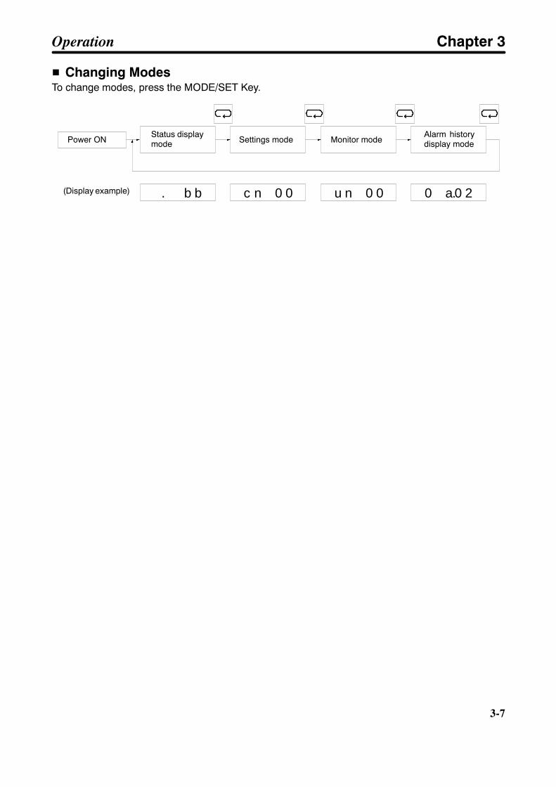
3-7
H Changing ModesTo change modes, press the MODE/SET Key.
. b b c n 0 0 u n 0 0 0 a.0 2
Power ON
(Display example)
Status displaymode Settings mode Monitor mode
Alarm historydisplay mode
Operation Chapter 3
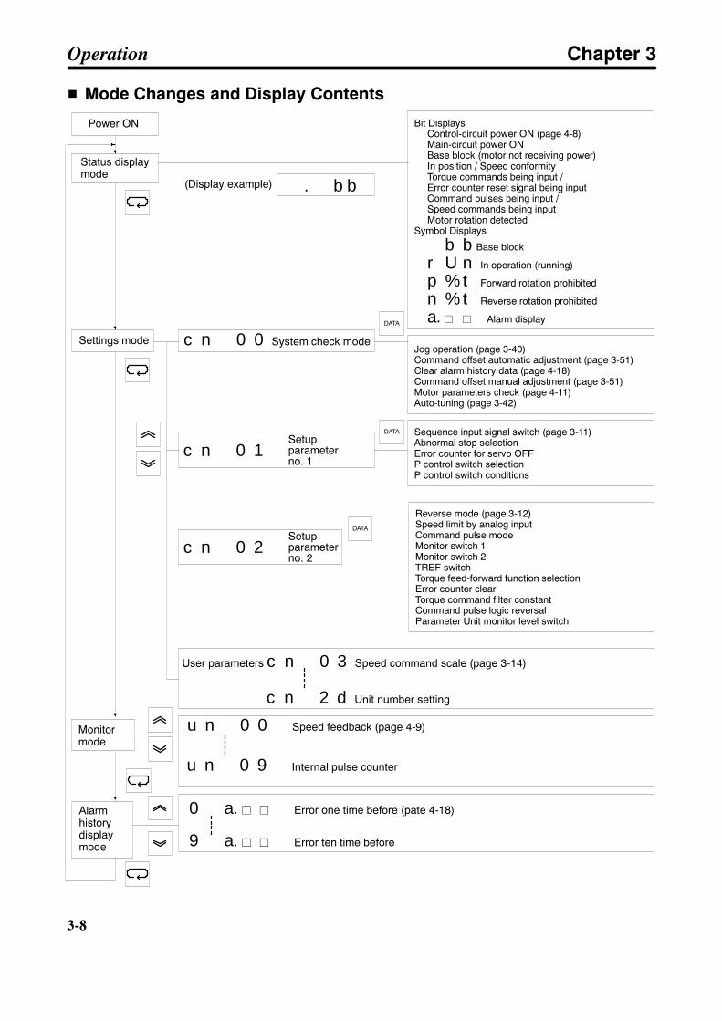
3-8
3-8
H Mode Changes and Display Contents
Reverse mode (page 3-12)Speed limit by analog inputCommand pulse modeMonitor switch 1Monitor switch 2TREF switchTorque feed-forward function selectionError counter clearTorque command filter constantCommand pulse logic reversalParameter Unit monitor level switch
Power ON
Status displaymode
(Display example)
Bit DisplaysControl-circuit power ON (page 4-8)Main-circuit power ONBase block (motor not receiving power)In position / Speed conformityTorque commands being input /Error counter reset signal being inputCommand pulses being input /Speed commands being inputMotor rotation detected
Symbol Displays
b b Base block
r U n In operation (running)
p % t Forward rotation prohibited
n % t Reverse rotation prohibited
a. j j Alarm display
. b b
u n 0 0 Speed feedback (page 4-9)
Settings mode c n 0 0 System check modeJog operation (page 3-40)Command offset automatic adjustment (page 3-51)Clear alarm history data (page 4-18)Command offset manual adjustment (page 3-51)Motor parameters check (page 4-11)Auto-tuning (page 3-42)
Sequence input signal switch (page 3-11)Abnormal stop selectionError counter for servo OFFP control switch selectionP control switch conditions
Setupparameterno. 1
c n 0 1
DATA
Setupparameterno. 2
c n 0 2
DATA
User parameters c n 0 3 Speed command scale (page 3-14)
c n 2 d Unit number setting
Monitormode
Alarmhistorydisplaymode
0 a. j j Error one time before (pate 4-18)
9 a. j j Error ten time before
u n 0 9 Internal pulse counter
DATA
Operation Chapter 3

3-9
3-2 System Check Mode (Cn-00)
The various kinds of system checks can be carried out by setting data for parameterCn-00.
In system check mode, the following six kinds of checks can be carried out according to the data set forCn-00. This chapter explains these checks only in a general way. For details, see the references notedin the table below.
Set value Contents of check Explanation References00 Jog operation The motor can be operated by the Parameter Unit.
The rotation speed is set by user parameter Cn-10(jog speed).
Section 3-4
01 Command offset auto-matic adjustment
Automatically adjusts speed command and torquecommand input offset. Treat speed command andtorque command inputs as 0 V.
Section 3-5-3
02 Alarm history data clear Clears history data for alarms that were previouslygenerated.
Section 4-4-1
03 Command offsetmanual adjustment
Speed command input offset is adjusted manually. Section 3-5-3
04 Motor parameter check Checks whether the Servo Driver and Servomotorare correctly aligned.
Section 4-2-4
05 Auto-tuning Operates the motor and automatically adjusts theposition loop gain, speed loop gain, and speedloop integration constant. The rotation speed is 1/2of that set by the user parameter Cn-10 (jogspeed).
Section 3-5-1
Operation Chapter 3
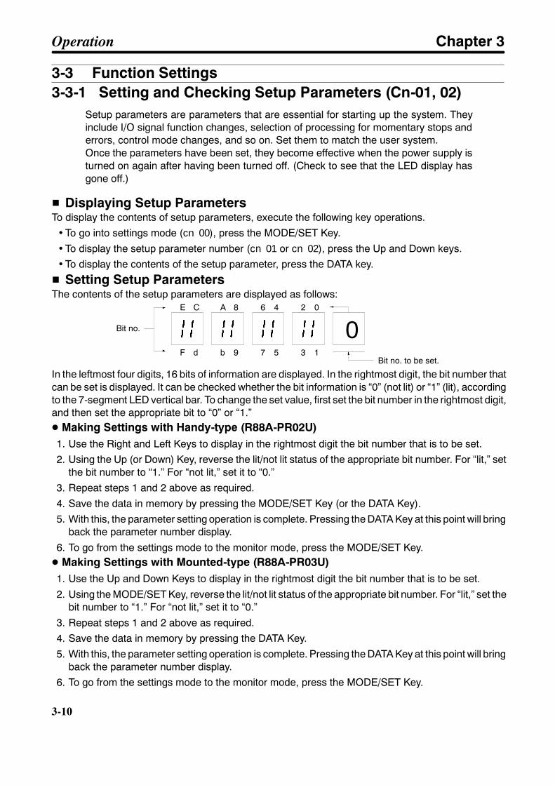
3-10
3-10
3-3 Function Settings3-3-1 Setting and Checking Setup Parameters (Cn-01, 02)
Setup parameters are parameters that are essential for starting up the system. Theyinclude I/O signal function changes, selection of processing for momentary stops anderrors, control mode changes, and so on. Set them to match the user system.Once the parameters have been set, they become effective when the power supply isturned on again after having been turned off. (Check to see that the LED display hasgone off.)
H Displaying Setup ParametersTo display the contents of setup parameters, execute the following key operations.
• To go into settings mode (cn00), press the MODE/SET Key.
• To display the setup parameter number (cn01 or cn02), press the Up and Down keys.• To display the contents of the setup parameter, press the DATA key.
H Setting Setup ParametersThe contents of the setup parameters are displayed as follows:
0E C A 8 6 4 2 0
F d b 9 7 5 3 1
Bit no.
Bit no. to be set.
In the leftmost four digits, 16 bits of information are displayed. In the rightmost digit, the bit number thatcan be set is displayed. It can be checked whether the bit information is “0” (not lit) or “1” (lit), accordingto the 7-segment LED vertical bar. To change the set value, first set the bit number in the rightmost digit,and then set the appropriate bit to “0” or “1.”D Making Settings with Handy-type (R88A-PR02U)1. Use the Right and Left Keys to display in the rightmost digit the bit number that is to be set.2. Using the Up (or Down) Key, reverse the lit/not lit status of the appropriate bit number. For “lit,” set
the bit number to “1.” For “not lit,” set it to “0.”
3. Repeat steps 1 and 2 above as required.
4. Save the data in memory by pressing the MODE/SET Key (or the DATA Key).5. With this, the parameter setting operation is complete. Pressing the DATA Key at this point will bring
back the parameter number display.
6. To go from the settings mode to the monitor mode, press the MODE/SET Key.D Making Settings with Mounted-type (R88A-PR03U)1. Use the Up and Down Keys to display in the rightmost digit the bit number that is to be set.
2. Using the MODE/SET Key, reverse the lit/not lit status of the appropriate bit number. For “lit,” set thebit number to “1.” For “not lit,” set it to “0.”
3. Repeat steps 1 and 2 above as required.4. Save the data in memory by pressing the DATA Key.
5. With this, the parameter setting operation is complete. Pressing the DATA Key at this point will bringback the parameter number display.
6. To go from the settings mode to the monitor mode, press the MODE/SET Key.
Operation Chapter 3
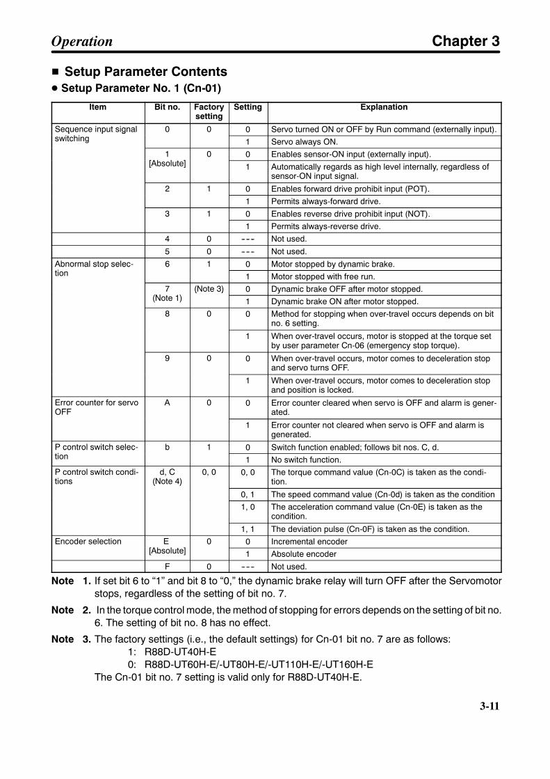
3-11
H Setup Parameter ContentsD Setup Parameter No. 1 (Cn-01)
Item Bit no. Factorysetting
Setting Explanation
Sequence input signalswitching
0 0 0 Servo turned ON or OFF by Run command (externally input).Sequence input signalswitching
0 0
1 Servo always ON.1
[Absolute]0 0 Enables sensor-ON input (externally input).1
[Absolute]0
1 Automatically regards as high level internally, regardless ofsensor-ON input signal.
2 1 0 Enables forward drive prohibit input (POT).2 1
1 Permits always-forward drive.3 1 0 Enables reverse drive prohibit input (NOT).3 1
1 Permits always-reverse drive.4 0 ------ Not used.
5 0 ------ Not used.Abnormal stop selec-tion
6 1 0 Motor stopped by dynamic brake.Abnormal stop selec-tion
6 1
1 Motor stopped with free run.7
(Note 1)(Note 3) 0 Dynamic brake OFF after motor stopped.7
(Note 1)(Note 3)
1 Dynamic brake ON after motor stopped.8 0 0 Method for stopping when over-travel occurs depends on bit
no. 6 setting.
1 When over-travel occurs, motor is stopped at the torque setby user parameter Cn-06 (emergency stop torque).
9 0 0 When over-travel occurs, motor comes to deceleration stopand servo turns OFF.
1 When over-travel occurs, motor comes to deceleration stopand position is locked.
Error counter for servoOFF
A 0 0 Error counter cleared when servo is OFF and alarm is gener-ated.OFF
1 Error counter not cleared when servo is OFF and alarm isgenerated.
P control switch selec-tion
b 1 0 Switch function enabled; follows bit nos. C, d.P control switch selec-tion
b 1
1 No switch function.P control switch condi-tions
d, C(Note 4)
0, 0 0, 0 The torque command value (Cn-0C) is taken as the condi-tion.tions (Note 4)
0, 1 The speed command value (Cn-0d) is taken as the condition1, 0 The acceleration command value (Cn-0E) is taken as the
condition.
1, 1 The deviation pulse (Cn-0F) is taken as the condition.Encoder selection E
[Absolute]0 0 Incremental encoderEncoder selection E
[Absolute]0
1 Absolute encoderF 0 ------ Not used.
Note 1. If set bit 6 to “1” and bit 8 to “0,” the dynamic brake relay will turn OFF after the Servomotorstops, regardless of the setting of bit no. 7.
Note 2. In the torque control mode, the method of stopping for errors depends on the setting of bit no.6. The setting of bit no. 8 has no effect.
Note 3. The factory settings (i.e., the default settings) for Cn-01 bit no. 7 are as follows:1: R88D-UT40H-E0: R88D-UT60H-E/-UT80H-E/-UT110H-E/-UT160H-E
The Cn-01 bit no. 7 setting is valid only for R88D-UT40H-E.
Operation Chapter 3

3-12
3-12
Note 4. With P control switch conditions, a change from PI control to P control is selected. This func-tion is not valid for torque control.
Note 5. Do not change the settings of bit nos. 1, 4, 5, E, and F of setup parameter no. 1 (Cn-01).
Note 6. These parameters become effective only after power is reset. Confirm that the indicators goout before turning power back on. (Check to see that the LED display has gone off.)
D Setup Parameter No. 2 (Cn-02)Item Bit no. Factory
settingSetting Explanation
Reverse rotation mode 0 0 0 CCW direction is taken upon “+” command. (See note 5.)Reverse rotation mode 0 0
1 CW direction is taken upon “+” command.Origin error mask 1
[Absolute]0 0 Origin errors are detected.Origin error mask 1
[Absolute]0
1 Origin errors are not detected.Speed limit by analoginput (for torque control)
2 0 0 Disabled.Speed limit by analoginput (for torque control)
2 0
1 Enabled.Command pulse mode 5, 4, 3 0, 0, 1 0, 0, 0 Feed pulses / Forward/reverse signalCommand pulse mode 5, 4, 3 0, 0, 1
0, 0, 1 Forward pulses / Reverse pulses0, 1, 0 90° phase difference (A/B phase) signal (x1)0, 1, 1 90° phase difference (A/B phase) signal (x2)1, 0, 0 90° phase difference (A/B phase) signal (x4)
Monitor switch 1 6 0 0 AM terminal is taken as current monitor output terminal.Monitor switch 1 6 0
1 AM terminal is taken as speed command / command pulsespeed monitor output terminal. (See note 3.)
Monitor switch 2 7 0 0 NM terminal is taken as speed monitor output terminal.Monitor switch 2 7 0
1 NM terminal is taken as error counter monitor output termi-nal. (See note 4.)
TREF switch (for speedcontrol)
8 0 0 Current limit is disabled by TREF.TREF switch (for speedcontrol)
8 0
1 Current limit is enabled by TREF.Torque feed-forwardfunction selection (for
9 0 0 No torque feed-forward function.function selection (forspeed control) 1 Torque feed-forward function enabled.
Error counter clear (forposition control)
A 1 0 Error counter cleared by status (high level).Error counter clear (forposition control)
A 1
1 Error counter cleared by differentiation (rising edge).b 0 ------ Not used.
Torque command filtertime constant
C 0 0 Primary filterTorque command filtertime constant
C 0
1 Secondary filterCommand pulse logicreversal (for position
d 0 0 Positive logicreversal (for positioncontrol) 1 Negative logic
Parameter Unit monitoroutput level change (for
E 0 0 Deviation monitor taken as x1 command units.output level change (forposition control) 1 Deviation monitor taken as x100 command units.
F 0 ------ Not used.
Note 1. Do not change the settings of bit nos. 1, b, and F of setup parameter no. 2 (Cn-02).
Note 2. Parameters other than bit nos. 6 and 7 of setup parameter no. 2 (Cn-02) become effectiveonly after power is reset. Confirm that the indicators go out before turning power back on.(Check to see that the LED display has gone off.)
Operation Chapter 3

3-13
Note 3. The function will vary depending on the control mode that is selected.Position control: Command pulse speed monitor (1 V @ 1,000 r/min)Speed control: Speed command monitor
2 V @ (1,000 r/min): 1,500-r/min models1 V @ (1,000 r/min): 3,000-r/min models
Torque control: (Disabled: 0 V)Note 4. The function will vary depending on the control mode that is selected.
Position control: Error counter monitor (when 0.05 V @ command unit: Cn-02 bitno. E = 0)
Speed control: (Disabled: 0 V)Torque control: (Disabled: 0 V)
Note 5. CCW direction refers to counterclockwise rotation and CW direction refers to clockwise rota-tion when viewed from the motor output side.
D Important Setup Parameters (Cn-01 and Cn-02)This section explains the particularly important setup parameters. If these parameters aren’t set prop-erly, the motor might not operate or might operate unpredictably. Set these parameters appropriately forthe system being used.
Command Pulse Types (for Position Control, Cn-02 Bit Nos. 5, 4, and 3)Set the command pulse mode for position control according to the pulse command configuration.
Command pulse mode(Cn-02 bit nos. 5, 4, 3)
Selected command pulse mode
0, 0, 0 Feed pulses (PULS) / Forward/reverse signal (SIGN)0, 0, 1 Forward pulses (CCW) / Reverse pulses (CW) (Factory setting)0, 1, 0 90° phase difference (A/B phase) signal (x1)0, 1, 1 90° phase difference (A/B phase) signal (x2)1, 0, 0 90° phase difference (A/B phase) signal (x4)
Note 1. When a 90° phase difference signal is input, any of three types of multipliers can be selected:x1, x2, or x4. If x4 is selected, the input pulses will be multiplied by four, so the number of motorrevolutions (speed, angle) will be four times that of x1.
Note 2. The control mode, such as the speed control, position control, or torque control mode, is setwith the user parameter Cn-2D. Refer to 3-3-3 Important User Parameters for details.
Error Stop ProcessesBits 6, 7, 8, and 9 of Cn-01 specify how the motor will be stopped when the servo goes OFF (the runcommand is OFF), an alarm is generated, or overtravel occurs. The following diagrams show the func-tion of these four bits:
Stop Process for Servo OFF/Alarm
Servo OFFor Alarm
Bit 6
Deceleration method
Decelerate by dynamic brake.
Decelerate by free run.
Bit 7 Stop condition
Servo free (dynamic brake OFF)
Servo free (dynamic brake ON)
Servo free (dynamic brake OFF)
0
1
0
1
Operation Chapter 3

3-14
3-14
Note Bit no. 7 is not valid for the R88-UT60H-E Servo Driver or higher-grade Servo Drivers. At the timeof stopping, the dynamic brake turns OFF.
Stop Process for Overtravel
Overtraveloccurs.
Bit 8
Deceleration method
Decelerate by dynamic brake.
Decelerate by free run.
Bit 9
Stop condition
Servo free (dynamic brake OFF)
Servo free (dynamic brake OFF)
Bit 6
Decelerate by emergency stoptorque (Cn-06).
0
1
0
1
Servo lock
0
1
3-3-2 Setting and Checking User Parameters (Cn-03 to 2d)
Execute the user parameter settings in order as follows:Go into settings mode MODE/SET Key. . . . . . . . . . . . . . . . . . . . . . .
Display the pertinent parameter number Direction Keys (Handy-type). . . . . . .Up and Down Keys (Mounted-type)
Display the contents (data) of the parameter DATA Key. . . .
Change the data Direction Keys (Handy-type). . . . . . . . . . . . . . . . . . . . . . . . . . . .Up and Down Keys (Mounted-type)
Save the data in memory MODE/SET and DATA Keys. . . . . . . . . . . . . . . . . . . . .
H Checking User ParametersThe contents of a given user parameter can be checked by pressing the DATA Key while that parameternumber is being displayed. Pressing the DATA Key again will bring back the parameter number display.(See the illustration below.)
c n 0 3 0 0 3 0 0
[1] [2]
[5] [4]
DATA
DATA
Parameter Number Display Data Display
H Setting User ParametersUse the following procedures to set user parameters.
D Making Settings with Handy-type (R88A-PR02U)
1. Use the Direction Keys to display the number of the parameter that is to be set.Using the Right and Left Keys, select the digit that is to be set. The digit for which the number can bechanged will blink.With the Up and Down Keys, increment or decrement the number for that digit.
2. Press the DATA Key. The contents (data) of the pertinent parameter will be displayed.
Operation Chapter 3

3-15
3. Using the Direction Keys, set the data. The method is the same as for step 1 above.
4. Save the data in memory by pressing the MODE/SET Key (or the DATA Key).
5. Pressing the DATA Key again will bring back the parameter number display.
6. Repeat steps 1 through 5 above as required.
D Making Settings with Mounted-type (R88A-PR03U)
1. Use the Up and Down keys to display the number of the parameter that is to be set.
2. Press the DATA Key. The contents (data) of the pertinent parameter will be displayed.
3. Using the Up and Down Keys, set the data. If the keys are held down, the numbers will change 10 ata time. If the keys are held down even longer, the numbers will change 100 and then 1,000 at a time.
4. Save the data in memory by pressing the MODE/SET Key (or the DATA Key).
5. Pressing the DATA Key again will bring back the parameter number display.
6. Repeat steps 1 through 5 above as required.
H User Parameter ChartPRMNo.
Parameter name Factorysetting
Unit Settingrange
Explanation
Cn-00 System check mode --- --- --- Refer to system check modeexplanation.
Cn-01 Setup parameter no. 1 --- --- --- Refer to setup parameter no.1 explanation.
Cn-02 Setup parameter no. 2 --- --- --- Refer to setup parameter no.2 explanation.
Cn-03 Speed command scale 300 (r/min)/V 10 to 2,000 Rotation speed setting per 1 Vof speed command voltage.
Cn-04 Speed loop gain (Seenote 1.)
80 Hz 1 to 2,000 Adjusts speed loop response.
Cn-05 Speed loop integrationconstant
2,000 0.01 ms 200 to51,200
Speed loop integration con-stant
Cn-06 Emergency stop torque 350 % 0 to 350 Deceleration torque whenabnormality occurs (comparedto rated torque).
Cn-07 Soft start accelerationtime (Note 4)
0 ms 0 to 10,000 Acceleration time setting forsoft start.
Cn-08 Forward torque limit 350 % 0 to 350 Output torque for rotation inforward direction (comparedto rated torque).
Cn-09 Reverse torque limit 350 % 0 to 350 Output torque for rotation inreverse direction (comparedto rated torque).
Cn-0A Encoder divider rate (Seenote 2.)
1,000 Pulses/revolution
16 to 8,192(Note 6)
Setting for number of outputpulses from Servo Driver.
Cn-0b Rotation speed for motorrotation detection
20 r/min 1 to 4,500(Note 8)
Setting for rotation speed formotor rotor detection output.
Cn-0C P control switching(torque commands)
200 % 0 to 350 If a torque command exceedsthis value, the mode switchesfrom PI to P control.
Operation Chapter 3

3-16
3-16
PRMNo.
ExplanationSettingrange
UnitFactorysetting
Parameter name
Cn-0d P control switching (speedcommands)
0 r/min 0 to 4,500(Note 8)
If a speed command exceedsthis value, the mode switchesfrom PI to P control.
Cn-0E P control switching (accel-eration commands)
0 10(r/min)/s
0 to 3,000 If an acceleration commandexceeds this value, the modeswitches from PI to P control.
Cn-0F P control switching (devi-ation pulses)
10 Com-mand
0 to 10,000 If the deviation pulses exceedthis value, the mode switchesfrom PI to P control.
Cn-10 Jog speed 500 r/min 0 to 4,500(Note 8)
Setting for manual rotationspeed
Cn-11 Number of encoderpulses (Notes 2 and 5)
8,192 Pulses/revolution
1,500-r/min:8,1923,000-r/min[INC]: 4,096[ABS]: 8,192
Setting for number of pulsesfor encoder used.
Cn-12 Brake timing 1 0 10 ms 0 to 50 Delay time setting from brakecommand until servo turns off.
Cn-13 Torque command scale 30 0.1V/ratedtorque
10 to 100 Sets gain for torque commandinput.
Cn-14 Speed limit 1,500 r/min 0 to 4,500(Note 8)
Sets speed limit value fortorque control mode.
Cn-15 Brake command speed 100 r/min 0 to 4,500(Note 8)
Sets rotation speed for output-ting brake commands.
Cn-16 Brake timing 2 50 10 ms 10 to 100 Waiting time from servo-off tobrake command output.
Cn-17 Torque command filtertime constant
4 100 µs 0 to 250 Setting for torque commandfilter time constant (6.4 to398 Hz).
Cn-18 Forward rotation externalcurrent limit
100 % 0 to 350 Output torque for when for-ward rotation current limit isinput (compared to ratedtorque).
Cn-19 Reverse rotation externalcurrent limit
100 % 0 to 350 Output torque for whenreverse rotation current limit isinput (compared to ratedtorque).
Cn-1A Position loop gain 40 1/s 1 to 1,000 Adjusts the position loopresponse.
Cn-1b Positioning completionrange
3 Com-mands
0 to 250 Positioning completion signaloutput range setting
Cn-1C Bias rotational speed 0 r/min 0 to 450 Position control bias setting
Cn-1d Feed-forward amount 0 % 0 to 100 Position control feed-forwardcompensation value
Cn-1E Differential counter over-flow level
1,024 x256command
1 to 32,767 Setting for detection of errorcounter overrun
Cn-1F No. 1 internal speed set-ting
100 r/min 0 to 4,500(Note 8)
Rotation speed, no. 1 internalsetting
Cn-20 No. 2 internal speed set-ting
200 r/min 0 to 4,500(Note 8)
Rotation speed, no. 2 internalsetting
Operation Chapter 3
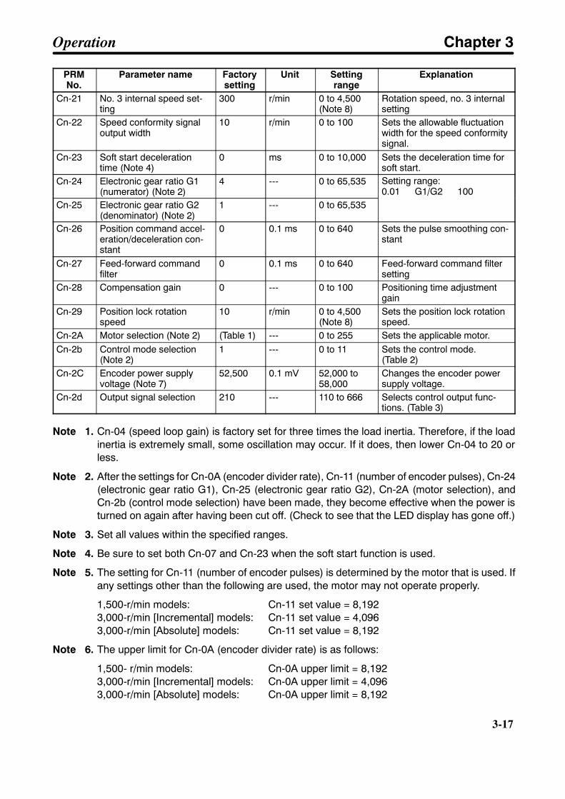
3-17
PRMNo.
ExplanationSettingrange
UnitFactorysetting
Parameter name
Cn-21 No. 3 internal speed set-ting
300 r/min 0 to 4,500(Note 8)
Rotation speed, no. 3 internalsetting
Cn-22 Speed conformity signaloutput width
10 r/min 0 to 100 Sets the allowable fluctuationwidth for the speed conformitysignal.
Cn-23 Soft start decelerationtime (Note 4)
0 ms 0 to 10,000 Sets the deceleration time forsoft start.
Cn-24 Electronic gear ratio G1(numerator) (Note 2)
4 --- 0 to 65,535 Setting range:0.01 G1/G2 100
Cn-25 Electronic gear ratio G2(denominator) (Note 2)
1 --- 0 to 65,5350.01 G1/G2 100
Cn-26 Position command accel-eration/deceleration con-stant
0 0.1 ms 0 to 640 Sets the pulse smoothing con-stant
Cn-27 Feed-forward commandfilter
0 0.1 ms 0 to 640 Feed-forward command filtersetting
Cn-28 Compensation gain 0 --- 0 to 100 Positioning time adjustmentgain
Cn-29 Position lock rotationspeed
10 r/min 0 to 4,500(Note 8)
Sets the position lock rotationspeed.
Cn-2A Motor selection (Note 2) (Table 1) --- 0 to 255 Sets the applicable motor.Cn-2b Control mode selection
(Note 2)1 --- 0 to 11 Sets the control mode.
(Table 2)Cn-2C Encoder power supply
voltage (Note 7)52,500 0.1 mV 52,000 to
58,000Changes the encoder powersupply voltage.
Cn-2d Output signal selection 210 --- 110 to 666 Selects control output func-tions. (Table 3)
Note 1. Cn-04 (speed loop gain) is factory set for three times the load inertia. Therefore, if the loadinertia is extremely small, some oscillation may occur. If it does, then lower Cn-04 to 20 orless.
Note 2. After the settings for Cn-0A (encoder divider rate), Cn-11 (number of encoder pulses), Cn-24(electronic gear ratio G1), Cn-25 (electronic gear ratio G2), Cn-2A (motor selection), andCn-2b (control mode selection) have been made, they become effective when the power isturned on again after having been cut off. (Check to see that the LED display has gone off.)
Note 3. Set all values within the specified ranges.
Note 4. Be sure to set both Cn-07 and Cn-23 when the soft start function is used.
Note 5. The setting for Cn-11 (number of encoder pulses) is determined by the motor that is used. Ifany settings other than the following are used, the motor may not operate properly.
1,500-r/min models: Cn-11 set value = 8,1923,000-r/min [Incremental] models: Cn-11 set value = 4,0963,000-r/min [Absolute] models: Cn-11 set value = 8,192
Note 6. The upper limit for Cn-0A (encoder divider rate) is as follows:
1,500- r/min models: Cn-0A upper limit = 8,1923,000-r/min [Incremental] models: Cn-0A upper limit = 4,0963,000-r/min [Absolute] models: Cn-0A upper limit = 8,192
Operation Chapter 3

!
!
3-18
3-18
Caution The Cn-2C (encoder power supply voltage) setting depends on the encoder cablelength. The encoder may be damaged if the setting is wrong. Refer to the followingtable when making the setting.
Encoder 3 m 5 m 10 m 15 m 20 m[Incremental] 52,500 54,000 55,500[Absolute] 52,500 55,000 57,000
Note 7. The parameters Cn-0b, Cn-0d, Cn-10, Cn-14, Cn-15, Cn-1F, Cn-20, Cn-21, and Cn-29 canbe set to a maximum value of 3,000 for the 1,500-r/min models and a maximum value of 4,500for the 3,000-r/min models.
D Table 1: Cn-2A (Motor Selection)
Caution Check to be sure that these settings are made correctly. If they are set incorrectly, themotor may malfunction or suffer damage.
Servo Driver Factory-setvalue
Applicable motor model Set value
R88D-UT40H-E 144 R88M-U1K315H-jS1 144R88D-UT40H-E 144R88M-U1K530H-j 164
R88D-UT60H-E 145 R88M-U1K815H-jS1 145R88D-UT60H-E 145R88M-U2K030H-j 165
R88D-UT80H-E 146 R88M-U2K915H-jS1 146R88D-UT80H-E 146R88M-U3K030H-j 166
R88D-UT110H-E 147 R88M-U4K415H-jS1 147R88D-UT110H-E 147R88M-U4K030H-j 167R88M-U5K030H-j 168
R88D-UT160H-E 148 R88M-U5K515H-jS1 148R88D-UT24V-j 163 R88M-U1K030V-jS1/X-jS1 163R88D-UT40V-j 164 R88M-U1K315V-jS1/X-jS1 144R88D-UT40V-j 164
R88M-U1K530V-jS1/X-jS1 164R88D-UT60V-j 165 R88M-U1K815V-jS1/X-jS1 145R88D-UT60V-j 165
R88M-U2K030V-jS1/X-jS1 165R88D-UT80V-j 166 R88M-U2K915V-jS1/X-jS1 146R88D-UT80V-j 166
R88M-U3K030V-jS1/X-jS1 166R88D-UT110V 167 R88M-U4K415V-jS1/X-jS1 147R88D-UT110V 167
R88M-U4K030V-jS1/X-jS1 167R88M-U5K030V-jS1/X-jS1 168
R88D-UT160V-E 148 R88M-U5K515V-jS1/X-jS1 148
Operation Chapter 3
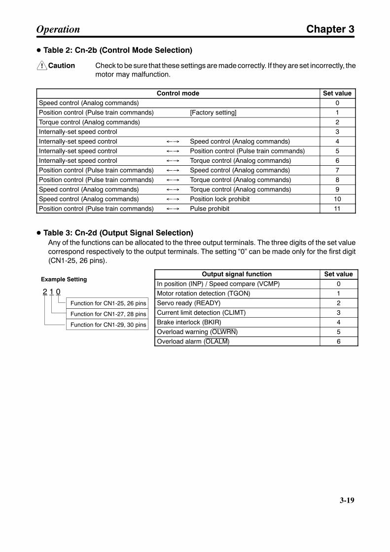
!
3-19
D Table 2: Cn-2b (Control Mode Selection)
Caution Check to be sure that these settings are made correctly. If they are set incorrectly, themotor may malfunction.
Control mode Set valueSpeed control (Analog commands) 0Position control (Pulse train commands) [Factory setting] 1Torque control (Analog commands) 2Internally-set speed control 3Internally-set speed control ←→ Speed control (Analog commands) 4Internally-set speed control ←→ Position control (Pulse train commands) 5Internally-set speed control ←→ Torque control (Analog commands) 6Position control (Pulse train commands) ←→ Speed control (Analog commands) 7Position control (Pulse train commands) ←→ Torque control (Analog commands) 8Speed control (Analog commands) ←→ Torque control (Analog commands) 9Speed control (Analog commands) ←→ Position lock prohibit 10Position control (Pulse train commands) ←→ Pulse prohibit 11
D Table 3: Cn-2d (Output Signal Selection)Any of the functions can be allocated to the three output terminals. The three digits of the set valuecorrespond respectively to the output terminals. The setting “0” can be made only for the first digit(CN1-25, 26 pins).
Output signal function Set valueIn position (INP) / Speed compare (VCMP) 0Motor rotation detection (TGON) 1Servo ready (READY) 2Current limit detection (CLIMT) 3Brake interlock (BKIR) 4Overload warning (OLWRN) 5Overload alarm (OLALM) 6
Example Setting
2 1 0Function for CN1-25, 26 pins
Function for CN1-27, 28 pins
Function for CN1-29, 30 pins
Operation Chapter 3

3-20
3-20
3-3-3 Important User ParametersThis section explains the checks and settings that are required before using the Servomotor and ServoDriver. These parameters must be set correctly. If they are set incorrectly, the motor may fail to operateor may malfunction. Make the appropriate settings for the system that is being used.
H Control Mode SettingsThe control mode is set by user parameter Cn-2b.
Control modes
Independent control modes
Internally-set speed controlmodes
Switching control modes
Control modes with addedfunctions
Speed control
Position control
Torque control
Internally-set speedcontrol
Internally-set speedcontrol + speed control
Internally-set speedcontrol + positioncontrol
Internally-set speedcontrol + torque control
Position control +speed control
Position control +torque control
Speed control + torquecontrol
Speed control withposition lock function
Position control (Pulseprohibit/enable)
0
1
2
3
4
5
6
7
8
9
10
11
Cn-2bset value
Operation Chapter 3
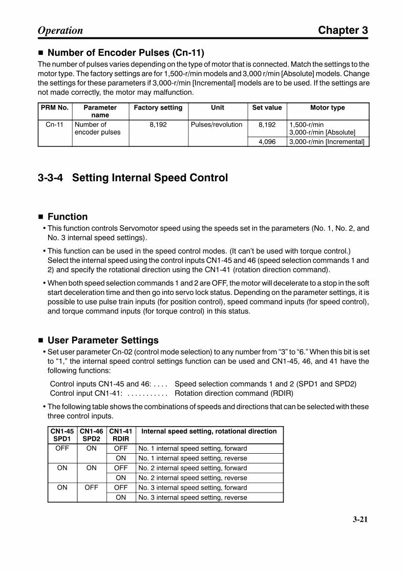
3-21
H Number of Encoder Pulses (Cn-11)The number of pulses varies depending on the type of motor that is connected. Match the settings to themotor type. The factory settings are for 1,500-r/min models and 3,000 r/min [Absolute] models. Changethe settings for these parameters if 3,000-r/min [Incremental] models are to be used. If the settings arenot made correctly, the motor may malfunction.
PRM No. Parametername
Factory setting Unit Set value Motor type
Cn-11 Number ofencoder pulses
8,192 Pulses/revolution 8,192 1,500-r/min3,000-r/min [Absolute]encoder pulses
4,096 3,000-r/min [Incremental]
3-3-4 Setting Internal Speed Control
H Function• This function controls Servomotor speed using the speeds set in the parameters (No. 1, No. 2, and
No. 3 internal speed settings).
• This function can be used in the speed control modes. (It can’t be used with torque control.)Select the internal speed using the control inputs CN1-45 and 46 (speed selection commands 1 and2) and specify the rotational direction using the CN1-41 (rotation direction command).
• When both speed selection commands 1 and 2 are OFF, the motor will decelerate to a stop in the softstart deceleration time and then go into servo lock status. Depending on the parameter settings, it ispossible to use pulse train inputs (for position control), speed command inputs (for speed control),and torque command inputs (for torque control) in this status.
H User Parameter Settings• Set user parameter Cn-02 (control mode selection) to any number from “3” to “6.” When this bit is set
to “1,” the internal speed control settings function can be used and CN1-45, 46, and 41 have thefollowing functions:
Control inputs CN1-45 and 46: Speed selection commands 1 and 2 (SPD1 and SPD2). . . .Control input CN1-41: Rotation direction command (RDIR). . . . . . . . . . .
• The following table shows the combinations of speeds and directions that can be selected with thesethree control inputs.
CN1-45SPD1
CN1-46SPD2
CN1-41RDIR
Internal speed setting, rotational direction
OFF ON OFF No. 1 internal speed setting, forwardOFF ONON No. 1 internal speed setting, reverse
ON ON OFF No. 2 internal speed setting, forwardON ONON No. 2 internal speed setting, reverse
ON OFF OFF No. 3 internal speed setting, forwardON OFFON No. 3 internal speed setting, reverse
Operation Chapter 3

3-22
3-22
D Internal Speed Control Settings Only: Control Mode Selection (Cn-2b = “3”)• Setting user parameter Cn-2b (control mode selection) to “3” specifies the “internal speed control
settings only” mode.
• When both SPD1 and SPD2 are OFF, the motor will decelerate to a stop and then go into servo lockstatus with an internal speed command status of 0 r/min. (Position lock will not be in effect.)
• Speed command inputs, pulse train inputs, and torque command inputs cannot be received.
D Internal Speed Control Settings + Speed Control: Control Mode Selection (Cn-2b =“4”)
• Setting user parameter Cn-2b (control mode selection) to “4” specifies the “internal speed controlsettings + speed control” mode.
• Speed control using internal speed settings and speed command inputs (REF) is possible in thiscontrol mode.
• Speed command inputs (REF) can be received from the point at which both SPD1 and SPD2 turnOFF.
D Internal Speed Control Settings + Position Control: Control Mode Selection (Cn-2b= “5”)
• Setting user parameter Cn-2b (control mode selection) to “5” specifies the “internal speed controlsettings + position control” mode.
• Speed control using internal speed settings and position control using pulse train inputs are possiblein this control mode.
• When both SPD1 and SPD2 are OFF, the motor will decelerate to a stop. When the positioning com-pletion signal is output, the position lock is in effect and the system is ready to receive the pulse com-mand input.
• Pulse commands can be input after the positioning completion (INP) signal turns ON. Pulses inputup until that point will be ignored. Likewise, when switching from position control to internally-setspeeds, wait until the positioning completion (INP) signal turns ON before turning ON the speedselection command. If the speed selection command is turned ON during command pulse input,command pulse transmission and positioning will be ended before switching to internally-setspeeds.
D Internal Speed Control Settings + Torque Control: Control Mode Selection (Cn-2b =“6”)
• Setting user parameter Cn-2b (control mode selection) to “6” specifies the “internal speed controlsettings + torque control” mode.
• Speed control using internal speed settings and torque control using torque command inputs(TREF) are possible in this control mode.
• Torque command inputs (TREF) can be received from the point at which both SPD1 and SPD2 turnOFF.
Operation Chapter 3

3-23
H Other User Parameter SettingsPRMNo.
Parameter name Factorysetting
Unit Settingrange
Explanation
Cn-07 Soft start acceleration time 0 ms 0 to 10,000 Sets the time for the motor toaccelerate from 0 r/min to maxi-mum instantaneous revolutions.
Cn-23 Soft start deceleration time 0 ms 0 to 10,000 Sets the time for the motor todecelerate from maximuminstantaneous revolutions to0 r/min.
Cn-26 Position command accelera-tion/deceleration constant
0 0.1 ms 0 to 640 Sets the constant for pulsesmoothing.
Cn-14 Speed control 1,500 r/min 0 to 4,500(Note 5)
Sets the speed limit for thetorque control mode.
Cn-1F No. 1 internal speed setting 100 r/min 0 to 4,500(Note 5)
Sets the speed for when SPD1is OFF and SPD2 is ON.
Cn-20 No. 2 internal speed setting 200 r/min 0 to 4,500(Note 5)
Sets the speed for when SPD1is ON and SPD2 is ON.
Cn-21 No. 3 internal speed setting 300 r/min 0 to 4,500(Note 5)
Sets the speed for when SPD1is ON and SPD2 is OFF.
Note 1. The soft start acceleration and deceleration times are effective on the internal speed settingsand the speed command input (REF).
Note 2. Acceleration and deceleration times are set up to the number of maximum instantaneous rev-olutions. The actual acceleration and deceleration times are found by means of the followingformula:
Actual acceleration (deceleration) time =Internally set speed (r/min)
Maximum instantaneousrevolutions (r/min)
Soft start acceleration(deceleration) time×
Motor speedMaximum instanta-neous revolutions(r/min)
Speed
Note 3. The position command acceleration/deceleration constant is effective on pulse commands.
Note 4. The speed limit setting is effective only in torque control mode.
Note 5. The parameters Cn-14, Cn-IF, Cn-20, and Cn-21 can be set to a maximum value of 3,000 forthe 1,500-r/min models and a maximum value of 4,500 for the 3,000-r/min models.
Operation Chapter 3
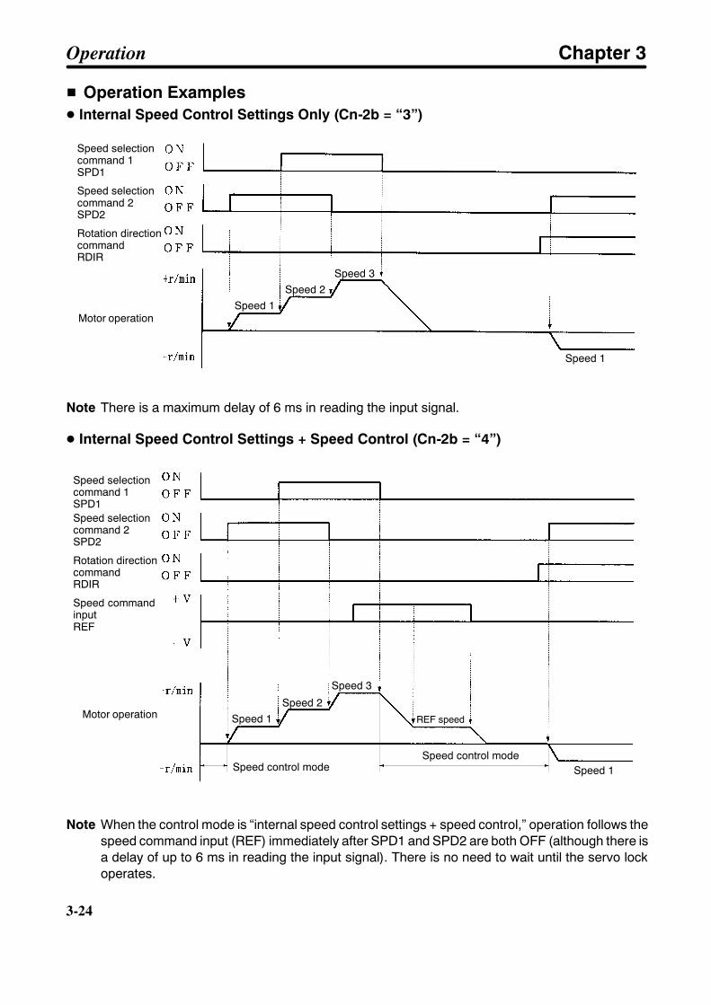
3-24
3-24
H Operation ExamplesD Internal Speed Control Settings Only (Cn-2b = “3”)
Speed selectioncommand 1SPD1
Speed selectioncommand 2SPD2
Rotation directioncommandRDIR
Motor operation
Speed 2Speed 3
Speed 1
Speed 1
Note There is a maximum delay of 6 ms in reading the input signal.
D Internal Speed Control Settings + Speed Control (Cn-2b = “4”)
Speed selectioncommand 1SPD1Speed selectioncommand 2SPD2
Rotation directioncommandRDIR
Speed commandinputREF
Motor operationSpeed 2
Speed 3
Speed 1
Speed 1
REF speed
Speed control modeSpeed control mode
Note When the control mode is “internal speed control settings + speed control,” operation follows thespeed command input (REF) immediately after SPD1 and SPD2 are both OFF (although there isa delay of up to 6 ms in reading the input signal). There is no need to wait until the servo lockoperates.
Operation Chapter 3

3-25
D Internal Speed Control Settings + Position Control (Cn-2b = “5”)Speed selectioncommand 1SPD1
Speed selectioncommand 2SPD2
Rotation directioncommandRDIR
Pulse command
Motor operationSpeed 2
Speed 3
Speed 1
Speed 1
Positioning com-pletion, INP(Speed compare,VCMP)
6 ms min.
6 ms min.
Note 1. There is a maximum delay of 6 ms in reading the input signal.
Note 2. The shaded areas in the time chart for the positioning completion signal indicate the placeswhere the signal is turned ON as the speed compare (VCMP) signal. (The meaning of thesignal differs according to the control mode.)
D Internal Speed Control Settings + Torque Control (Cn-2b = “6”)
Speed selectioncommand 1SPD1
Speed selectioncommand 2SPD2
Rotation directioncommandRDIR
Torque commandinputTREF
Motor operation
Speed 2Speed 3
Speed 1
Speed 1Torque control mode
Note 1. When the control mode is “internal speed control settings + torque control,” operation followsthe torque command input (TREF) immediately after SPD1 and SPD2 are both OFF(although there is a delay of up to 6 ms in reading the input signal).
Operation Chapter 3

3-26
3-26
Note 2. Motor operation with torque control varies according to the motor load conditions (e.g., fric-tion, external power, inertia).
Note 3. When motor servo-lock is required, set any of the internal speed settings to “0 r/min” andselect that speed with speed selection commands 1 and 2.
3-3-5 Switching Control ModeH Function
This function controls the motor by switching between two control modes by means of externalinputs. The control mode switching is executed at control input terminal CN1-41 (control modeswitching).
H User Parameter SettingsSet “7,” “8,” or “9” for user parameter Cn-2b (control mode selection). This setting causes controlinput terminal CN1-41 to become a control mode switching terminal (TVSEL). The following tablesshow the control modes.
Control mode Set valuePosition control (Pulse train command) ←→ Speed control (Analog command) 7Position control (Pulse train command) ←→ Torque control (Analog command) 8Speed control (Analog command) ←→ Speed control (Analog command) 9
Set value Selected Control ModeSet valueCN1-41: OFF CN1-41: ON
7 Position control Speed control8 Position control Torque control9 Torque control Speed control
H OperationD Position and Speed Control Switching Example (Cn-2b = “7”)
Control modeswitchingTVSEL
Speed commandinputREF
Pulse commands
Positioning com-pletion, INP(Speed compare,VCMP)
Motor operation
6 ms min.
6 ms min.
Operation Chapter 3

3-27
Note 1. There is a maximum delay of 6 ms in reading the input signal.
Note 2. When switching from speed control to position control, input the pulse command after thecontrol mode switching (TVSEL) has turned OFF, the positioning completion (INP) signal hasturned ON, and 6 ms has elapsed. The pulses will be ignored until the positioning completion(INP) signal has turned ON.
Note 3. The shaded areas in the time chart for the positioning completion signal indicate the placeswhere the signal is turned ON as the speed compare (VCMP) signal. (The meaning of thesignal differs according to the control mode.)
D Position and Torque Control Switching Example (Cn-2b = “8”)Control modeswitchingTVSEL
Torque commandinputTREF
Pulse commands
Positioning com-pletion signalINP
Motor operation
(Reverse operation)(Forward operation)
6 ms min.
Impact
6 ms min.
Note 1. This time chart shows an example of torque thrust.
Note 2. There is a maximum delay of 6 ms in reading the input signal.
Note 3. When switching from torque control to position control, input the pulse command after thecontrol mode switching (TVSEL) has turned OFF, the positioning completion (INP) signal hasturned ON, and 6 ms has elapsed. The pulses will be ignored until the positioning completion(INP) signal has turned ON.
Operation Chapter 3
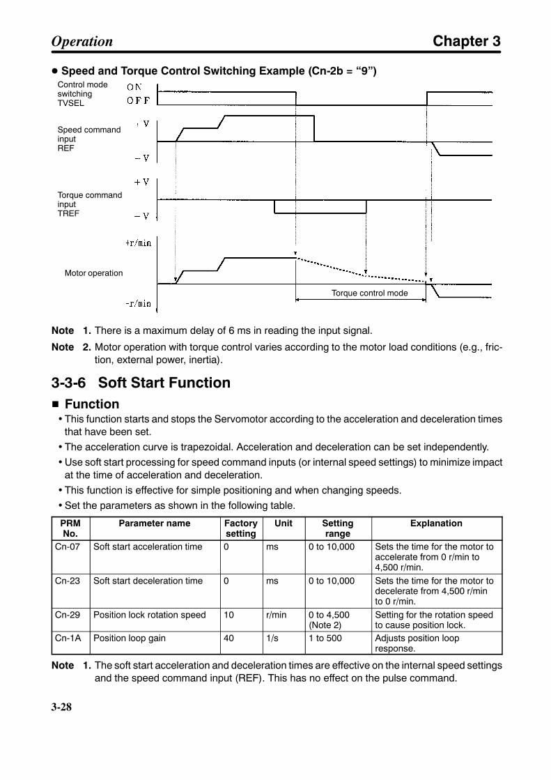
3-28
3-28
D Speed and Torque Control Switching Example (Cn-2b = “9”)Control modeswitchingTVSEL
Speed commandinputREF
Motor operation
Torque control mode
Torque commandinputTREF
Note 1. There is a maximum delay of 6 ms in reading the input signal.
Note 2. Motor operation with torque control varies according to the motor load conditions (e.g., fric-tion, external power, inertia).
3-3-6 Soft Start FunctionH Function
• This function starts and stops the Servomotor according to the acceleration and deceleration timesthat have been set.
• The acceleration curve is trapezoidal. Acceleration and deceleration can be set independently.• Use soft start processing for speed command inputs (or internal speed settings) to minimize impact
at the time of acceleration and deceleration.• This function is effective for simple positioning and when changing speeds.• Set the parameters as shown in the following table.
PRMNo.
Parameter name Factorysetting
Unit Settingrange
Explanation
Cn-07 Soft start acceleration time 0 ms 0 to 10,000 Sets the time for the motor toaccelerate from 0 r/min to4,500 r/min.
Cn-23 Soft start deceleration time 0 ms 0 to 10,000 Sets the time for the motor todecelerate from 4,500 r/minto 0 r/min.
Cn-29 Position lock rotation speed 10 r/min 0 to 4,500(Note 2)
Setting for the rotation speedto cause position lock.
Cn-1A Position loop gain 40 1/s 1 to 500 Adjusts position loopresponse.
Note 1. The soft start acceleration and deceleration times are effective on the internal speed settingsand the speed command input (REF). This has no effect on the pulse command.
Operation Chapter 3
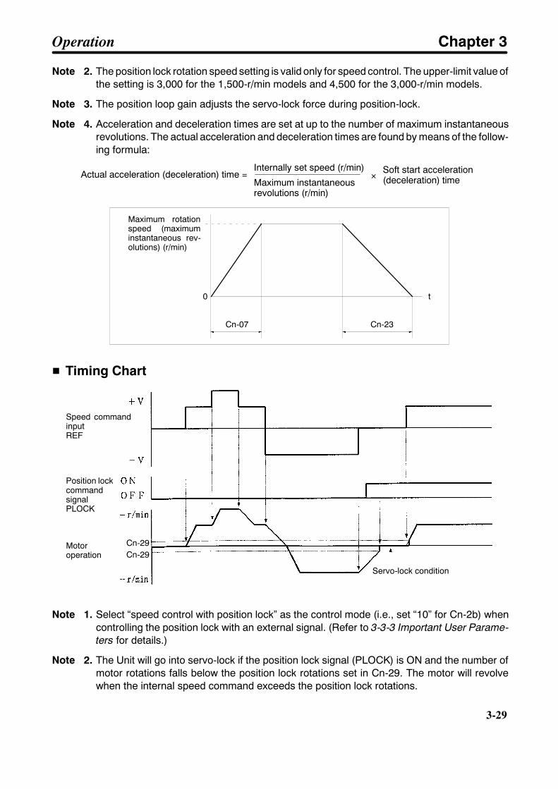
3-29
Note 2. The position lock rotation speed setting is valid only for speed control. The upper-limit value ofthe setting is 3,000 for the 1,500-r/min models and 4,500 for the 3,000-r/min models.
Note 3. The position loop gain adjusts the servo-lock force during position-lock.
Note 4. Acceleration and deceleration times are set at up to the number of maximum instantaneousrevolutions. The actual acceleration and deceleration times are found by means of the follow-ing formula:
Actual acceleration (deceleration) time =Internally set speed (r/min)
Maximum instantaneousrevolutions (r/min)
Soft start acceleration(deceleration) time×
0 t
Cn-07 Cn-23
Maximum rotationspeed (maximuminstantaneous rev-olutions) (r/min)
H Timing Chart
Speed commandinputREF
Position lockcommandsignalPLOCK
Motoroperation
Servo-lock condition
Cn-29Cn-29
Note 1. Select “speed control with position lock” as the control mode (i.e., set “10” for Cn-2b) whencontrolling the position lock with an external signal. (Refer to 3-3-3 Important User Parame-ters for details.)
Note 2. The Unit will go into servo-lock if the position lock signal (PLOCK) is ON and the number ofmotor rotations falls below the position lock rotations set in Cn-29. The motor will revolvewhen the internal speed command exceeds the position lock rotations.
Operation Chapter 3
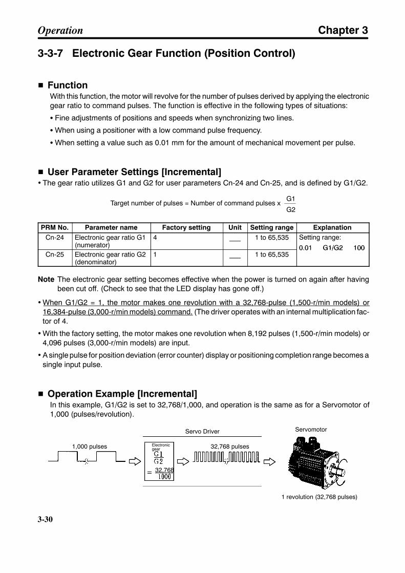
3-30
3-30
3-3-7 Electronic Gear Function (Position Control)
H FunctionWith this function, the motor will revolve for the number of pulses derived by applying the electronicgear ratio to command pulses. The function is effective in the following types of situations:
S Fine adjustments of positions and speeds when synchronizing two lines.
SWhen using a positioner with a low command pulse frequency.
SWhen setting a value such as 0.01 mm for the amount of mechanical movement per pulse.
H User Parameter Settings [Incremental]• The gear ratio utilizes G1 and G2 for user parameters Cn-24 and Cn-25, and is defined by G1/G2.
Target number of pulses = Number of command pulses xG1
G2
PRM No. Parameter name Factory setting Unit Setting range ExplanationCn-24 Electronic gear ratio G1
(numerator)4 ___ 1 to 65,535 Setting range:
0.01 G1/G2 100Cn-25 Electronic gear ratio G2
(denominator)1 ___ 1 to 65,535
0.01 G1/G2 100
Note The electronic gear setting becomes effective when the power is turned on again after havingbeen cut off. (Check to see that the LED display has gone off.)
• When G1/G2 = 1, the motor makes one revolution with a 32,768-pulse (1,500-r/min models) or16,384-pulse (3,000-r/min models) command. (The driver operates with an internal multiplication fac-tor of 4.
• With the factory setting, the motor makes one revolution when 8,192 pulses (1,500-r/min models) or4,096 pulses (3,000-r/min models) are input.
• A single pulse for position deviation (error counter) display or positioning completion range becomes asingle input pulse.
H Operation Example [Incremental]In this example, G1/G2 is set to 32,768/1,000, and operation is the same as for a Servomotor of1,000 (pulses/revolution).
1,000 pulses
Servo Driver
Electronicgear 32,768 pulses
Servomotor
1 revolution (32,768 pulses)
32,768
Operation Chapter 3
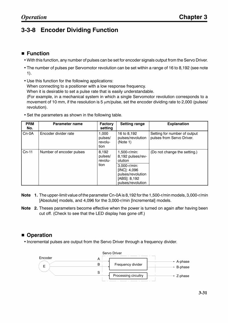
3-31
3-3-8 Encoder Dividing Function
H Function• With this function, any number of pulses can be set for encoder signals output from the Servo Driver.
• The number of pulses per Servomotor revolution can be set within a range of 16 to 8,192 (see note1).
• Use this function for the following applications:When connecting to a positioner with a low response frequency.When it is desirable to set a pulse rate that is easily understandable.(For example, in a mechanical system in which a single Servomotor revolution corresponds to amovement of 10 mm, if the resolution is 5 µm/pulse, set the encoder dividing rate to 2,000 (pulses/revolution).
• Set the parameters as shown in the following table.
PRMNo.
Parameter name Factorysetting
Setting range Explanation
Cn-0A Encoder divider rate 1,000pulses/revolu-tion
16 to 8,192pulses/revolution(Note 1)
Setting for number of outputpulses from Servo Driver.
Cn-11 Number of encoder pulses 8,192pulses/revolu-tion
1,500-r/min:8,192 pulses/rev-olution
(Do not change the setting.)
revolu-tion 3,000-r/min:
[INC]: 4,096pulses/revolution[ABS]: 8,192pulses/revolution
Note 1. The upper-limit value of the parameter Cn-0A is 8,192 for the 1,500-r/min models, 3,000-r/min[Absolute] models, and 4,096 for the 3,000-r/min [Incremental] models.
Note 2. Theses parameters become effective when the power is turned on again after having beencut off. (Check to see that the LED display has gone off.)
H Operation• Incremental pulses are output from the Servo Driver through a frequency divider.
E
A
B
S
EncoderServo Driver
Frequency divider
Processing circuitry
A-phase
B-phase
Z-phase
Operation Chapter 3
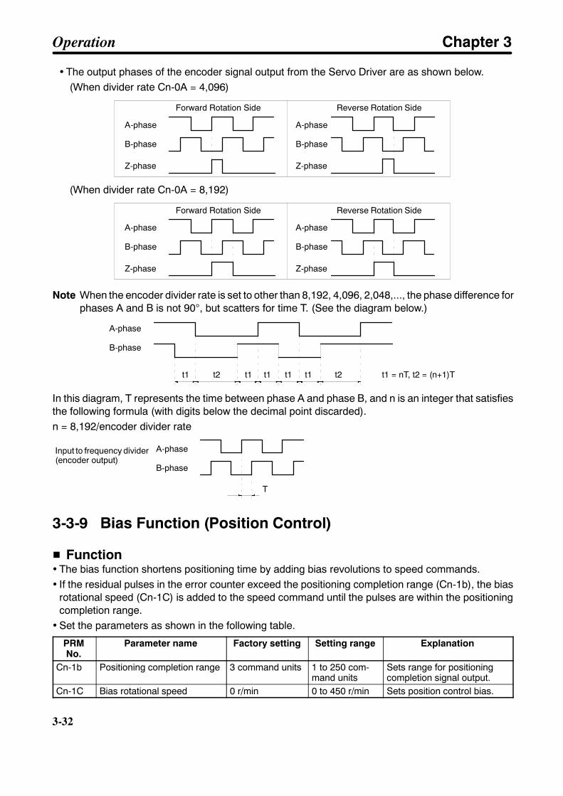
3-32
3-32
• The output phases of the encoder signal output from the Servo Driver are as shown below.(When divider rate Cn-0A = 4,096)
A-phase
B-phase
Z-phase
A-phase
B-phase
Z-phase
Forward Rotation Side Reverse Rotation Side
(When divider rate Cn-0A = 8,192)
A-phase
B-phase
Z-phase
A-phase
B-phase
Z-phase
Forward Rotation Side Reverse Rotation Side
Note When the encoder divider rate is set to other than 8,192, 4,096, 2,048,..., the phase difference forphases A and B is not 90°, but scatters for time T. (See the diagram below.)
t1 t2 t1 t1 t1 t1 t2 t1 = nT, t2 = (n+1)T
A-phase
B-phase
In this diagram, T represents the time between phase A and phase B, and n is an integer that satisfiesthe following formula (with digits below the decimal point discarded).n = 8,192/encoder divider rate
T
A-phase
B-phase
Input to frequency divider(encoder output)
3-3-9 Bias Function (Position Control)
H Function• The bias function shortens positioning time by adding bias revolutions to speed commands.• If the residual pulses in the error counter exceed the positioning completion range (Cn-1b), the bias
rotational speed (Cn-1C) is added to the speed command until the pulses are within the positioningcompletion range.
• Set the parameters as shown in the following table.
PRMNo.
Parameter name Factory setting Setting range Explanation
Cn-1b Positioning completion range 3 command units 1 to 250 com-mand units
Sets range for positioningcompletion signal output.
Cn-1C Bias rotational speed 0 r/min 0 to 450 r/min Sets position control bias.
Operation Chapter 3

3-33
Note 1. When not using the bias function, set the bias rotational speed to 0 r/min.
Note 2. If the bias rotational speed is set too high, it will cause motor operation to be unstable. Theoptimum setting depends on the load, the gain, and the positioning completion range, soadjust the setting while observing the motor response. (Begin with a bias setting of “0,” andgradually increase it.)
H Operation Example• In this example, the bias rotational speed (Cn-1C) is added to the error counter output (speed com-
mand) when the residual pulses in the error counter exceed the positioning completion range (Cn-1b).This continues until the residual pulses in the error counter are within the positioning completionrange, and then it stops.
• For the internal processing block configuration, refer to the position loop block diagram in 3-5-2 Manu-ally Adjusting Gain (Position Control).
Motor speed
Positioning com-pletion signalINP
Speed command(command pulsefrequency)
Motor speed withoutbias function
Motor speed withbias function
Shortened time
Time
3-3-10 Torque Limit Function (Position Control, Speed Control,Torque Control)
H Function• The torque limit function limits the Servomotor’s output torque; it can be used with position control,
speed control, and torque control.
• This function can be used to protect the Servomotor and machine system by preventing excessiveforce or torque on the machine system when the machine (moving part) pushes against the workpiecewith a steady force, such as in a bending machine.
• There are three methods that can be used to limit the torque:
1. Limit the steady force applied during normal operation with user parameters Cn-08 (forward torquelimit) and Cn-09 (reverse torque limit).
Operation Chapter 3
3-34
3-34
2. Limit operation with external signals connected to pins CN1-45 (PCL: forward current limit input)and CN1-46 (NCL: reverse current limit input). Set user parameters Cn-18 (forward rotation externalcurrent limit) and Cn-19 (reverse rotation external current limit).
3. Limit operation with analog voltage by using TREF (torque command input) as the analog currentlimit input.
H Parameter Settings
D Method 1: Limiting the Force Applied During Operation• User Parameter Settings
PRMNo.
Parametername
Factorysetting
Unit Setting range Explanation
Cn-08 Forwardtorque limit
Maximumtorque
% of ratedtorque
0 to maximumtorque
This parameter sets the output torquelimit for the forward direction (as a per-centage of the rated torque).
Cn-09 Reversetorque limit
Maximumtorque
% of ratedtorque
0 to maximumtorque
This parameter sets the output torquelimit for the reverse direction (as a per-centage of the rated torque).
Note 1. This method is effective with speed control, internal speed control settings, and torque control.
Note 2. Set these parameters to the maximum torque (the factory setting) when the torque limit function isn’tbeing used.
D Method 2: Limiting Operation with External Signals• Control Mode Selection (Cn-02 = 0 to 2, 7 to 11)
Set the control mode selection (Cn-2b) to a control mode other than internally-set speed control (3 to6).
With this setting, control input terminal CN1-45 will be PCL (forward current limit input), CN1-46 willbe NCL (reverse current limit input), and it will be possible to use the external current limit function.
• User Parameter Settings
PRMNo.
Parameter name Factorysetting
Unit Setting range Explanation
Cn-18 Forward rotationexternal current limit
100 % of ratedtorque
0 to maximumtorque
This parameter sets the limitwhen PCL is ON.
Cn-19 Reverse rotationexternal current limit
torque torqueThis parameter sets the limitwhen NCL is ON.
D Method 3: Limiting Operation with Analog Voltage• Setup Parameter Settings (Bit 8 of Cn-02 = 1)
Set bit 8 of Cn-02 (the TREF switch) to “1.” When bit 8 is “1,” terminals CN1-9 and CN1-10 (TREFand AGND) become analog current limit input terminals. The current limit value can be calculatedfrom the following equation:
Current limit value = (absolute value of voltage applied to TREF) × (torque command scale)
The polarity of the analog voltage is irrelevant and the same current limit value is used for forwardand reverse.
Operation Chapter 3

3-35
• User Parameter Settings
PRMNo.
Parametername
Factorysetting
Units Setting range Explanation
Cn-13 Torque com-mand scale
30 0.1 V/ratedtorque
10 to 100 This parameter sets the gain for thetorque command input.
Note 1. This method is useful when controlling torque in multiple stages.
Note 2. This method is effective with speed control and torque control.
Note 3. This method can’t be used when the torque feed-forward function is being used (i.e., when bit9 of Cn-02 is set to “1.”)
3-3-11 Speed Limit Function (Torque Control)
H Function• This function limits motor rotation speed when torque control is used. It sets a limit so that the motor
rotation speed does not exceed the maximum speed of the mechanical system.
• Outside of the speed limit range, a torque in proportion to the difference with the speed limit value isgenerated to slow down the motor rotation speed. In such cases the number of motor rotations doesnot necessarily match the speed limit value. (The number of motor rotations varies depending theload.)
• There are two methods that can be used for limiting the speed:
1. Apply a constant fixed speed limit for torque control, by means of user parameter Cn-14 (speedlimit).
2. Limit the speed by means of analog voltage. Use REF (speed command input) as an analog speedlimit input.
H Parameter Settings
D Applying a Constant Fixed Speed Limit for Torque Control• User Parameter Settings
PRMNo.
Parametername
Factorysetting
Units Setting range Explanation
Cn-14 Speed limit 1,500 r/min 0 to 4,500(Note)
This parameter sets the speed limit value fortorque control.
Note The upper-limit value of the parameter Cn-14 is 3,000 for the 1,500-r/min models and 4,500 forthe 3,000-r/min models.
D Limiting the Speed with Analog Voltage• Set bit no. 2 of setup parameter Cn-02 to “1.” When bit no. 2 is “1,” terminals CN1-5 and CN1-6 (REF
and AGND) become analog speed limit input terminals. The speed limit value can be calculated fromthe following equation:
Speed limit value = (absolute value of voltage applied to REF) × (speed command scale)
• If the voltage is positive, this becomes the speed limit value for both the forward and reverse direc-tions. (If the voltage is negative, this is regarded as a limit value of 0 r/min.
Operation Chapter 3
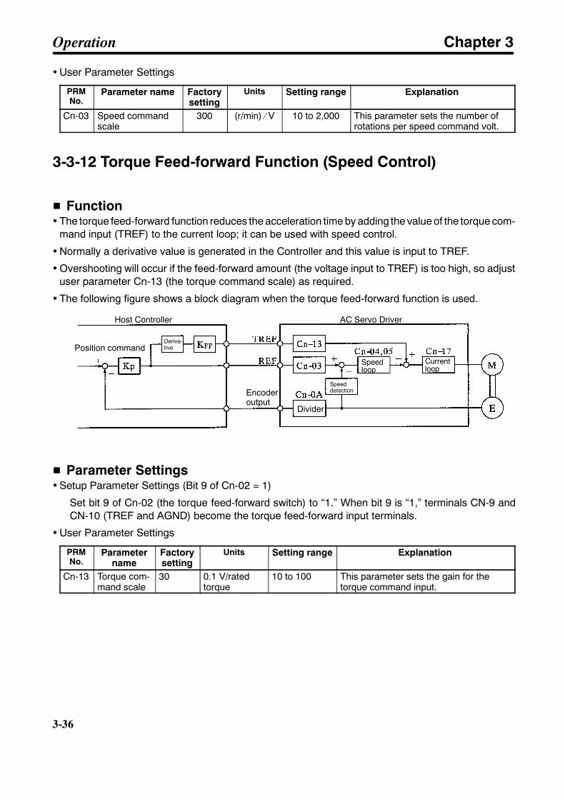
3-36
3-36
• User Parameter Settings
PRMNo.
Parameter name Factorysetting
Units Setting range Explanation
Cn-03 Speed commandscale
300 (r/min) ⁄ V 10 to 2,000 This parameter sets the number ofrotations per speed command volt.
3-3-12 Torque Feed-forward Function (Speed Control)
H Function• The torque feed-forward function reduces the acceleration time by adding the value of the torque com-
mand input (TREF) to the current loop; it can be used with speed control.
• Normally a derivative value is generated in the Controller and this value is input to TREF.
• Overshooting will occur if the feed-forward amount (the voltage input to TREF) is too high, so adjustuser parameter Cn-13 (the torque command scale) as required.
• The following figure shows a block diagram when the torque feed-forward function is used.
Host Controller AC Servo Driver
Position commandDeriva-tive
Encoderoutput
Divider
Speeddetection
Speedloop
Currentloop
H Parameter Settings• Setup Parameter Settings (Bit 9 of Cn-02 = 1)
Set bit 9 of Cn-02 (the torque feed-forward switch) to “1.” When bit 9 is “1,” terminals CN-9 andCN-10 (TREF and AGND) become the torque feed-forward input terminals.
• User Parameter Settings
PRMNo.
Parametername
Factorysetting
Units Setting range Explanation
Cn-13 Torque com-mand scale
30 0.1 V/ratedtorque
10 to 100 This parameter sets the gain for thetorque command input.
Operation Chapter 3
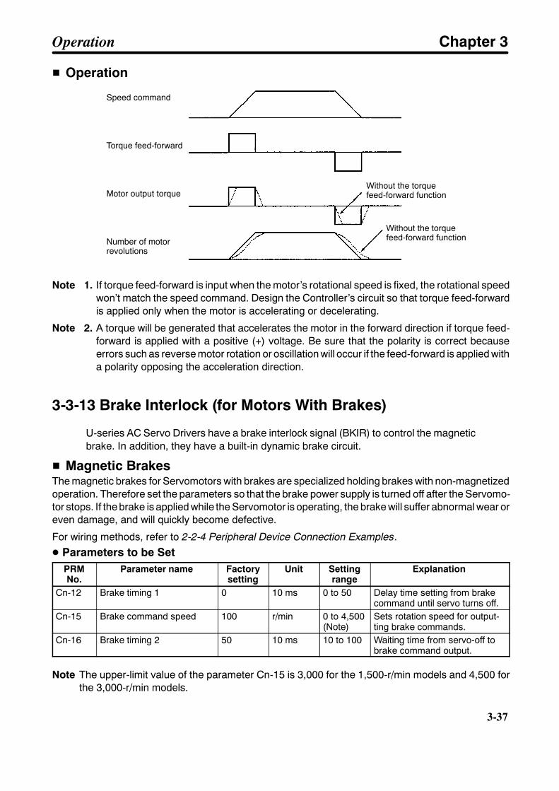
3-37
H Operation
Speed command
Torque feed-forward
Motor output torque
Number of motorrevolutions
Without the torquefeed-forward function
Without the torquefeed-forward function
Note 1. If torque feed-forward is input when the motor’s rotational speed is fixed, the rotational speedwon’t match the speed command. Design the Controller’s circuit so that torque feed-forwardis applied only when the motor is accelerating or decelerating.
Note 2. A torque will be generated that accelerates the motor in the forward direction if torque feed-forward is applied with a positive (+) voltage. Be sure that the polarity is correct becauseerrors such as reverse motor rotation or oscillation will occur if the feed-forward is applied witha polarity opposing the acceleration direction.
3-3-13 Brake Interlock (for Motors With Brakes)
U-series AC Servo Drivers have a brake interlock signal (BKIR) to control the magneticbrake. In addition, they have a built-in dynamic brake circuit.
H Magnetic BrakesThe magnetic brakes for Servomotors with brakes are specialized holding brakes with non-magnetizedoperation. Therefore set the parameters so that the brake power supply is turned off after the Servomo-tor stops. If the brake is applied while the Servomotor is operating, the brake will suffer abnormal wear oreven damage, and will quickly become defective.
For wiring methods, refer to 2-2-4 Peripheral Device Connection Examples.
D Parameters to be SetPRMNo.
Parameter name Factorysetting
Unit Settingrange
Explanation
Cn-12 Brake timing 1 0 10 ms 0 to 50 Delay time setting from brakecommand until servo turns off.
Cn-15 Brake command speed 100 r/min 0 to 4,500(Note)
Sets rotation speed for output-ting brake commands.
Cn-16 Brake timing 2 50 10 ms 10 to 100 Waiting time from servo-off tobrake command output.
Note The upper-limit value of the parameter Cn-15 is 3,000 for the 1,500-r/min models and 4,500 forthe 3,000-r/min models.
Operation Chapter 3
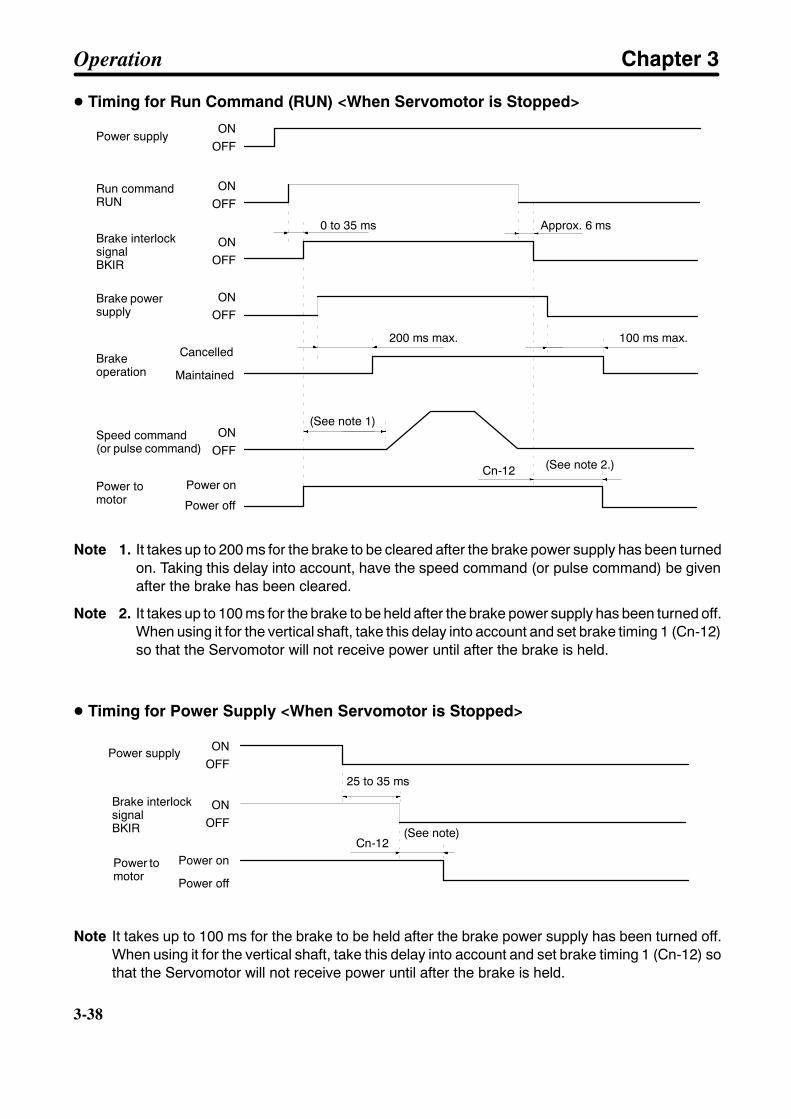
3-38
3-38
D Timing for Run Command (RUN) <When Servomotor is Stopped>
ONOFF
ONOFF
ONOFF
ONOFF
ONOFF
0 to 35 ms
200 ms max. 100 ms max.
(See note 1)
(See note 2.)Cn-12
Power supply
Run commandRUN
Brake interlocksignalBKIR
Brake powersupply
Brakeoperation
Cancelled
Maintained
Speed command(or pulse command)
Power tomotor
Power on
Power off
Approx. 6 ms
Note 1. It takes up to 200 ms for the brake to be cleared after the brake power supply has been turnedon. Taking this delay into account, have the speed command (or pulse command) be givenafter the brake has been cleared.
Note 2. It takes up to 100 ms for the brake to be held after the brake power supply has been turned off.When using it for the vertical shaft, take this delay into account and set brake timing 1 (Cn-12)so that the Servomotor will not receive power until after the brake is held.
D Timing for Power Supply <When Servomotor is Stopped>
ONOFF
ONOFF
25 to 35 ms
(See note)Cn-12
Power supply
Brake interlocksignalBKIR
Power tomotor
Power on
Power off
Note It takes up to 100 ms for the brake to be held after the brake power supply has been turned off.When using it for the vertical shaft, take this delay into account and set brake timing 1 (Cn-12) sothat the Servomotor will not receive power until after the brake is held.
Operation Chapter 3
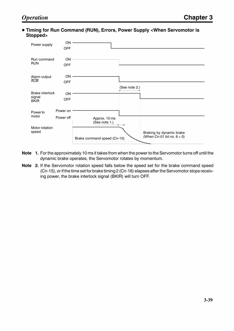
3-39
D Timing for Run Command (RUN), Errors, Power Supply <When Servomotor isStopped>
ON
OFF
ON
OFF
ON
OFF
ON
OFF
(See note 2.)
Power on
Power off
Power supply
Brake interlocksignalBKIR
Power tomotor
Run commandRUN
Alarm outputALM
Motor rotationspeed
Approx. 10 ms(See note 1.)
Brake command speed (Cn-15)
Braking by dynamic brake(When Cn-01 bit no. 6 = 0)
Note 1. For the approximately 10 ms it takes from when the power to the Servomotor turns off until thedynamic brake operates, the Servomotor rotates by momentum.
Note 2. If the Servomotor rotation speed falls below the speed set for the brake command speed(Cn-15), or if the time set for brake timing 2 (Cn-16) elapses after the Servomotor stops receiv-ing power, the brake interlock signal (BKIR) will turn OFF.
Operation Chapter 3
3-40
3-40
3-4 Trial OperationAfter the wiring is complete and the parameter settings have been made, conduct a trialoperation. Follow he procedure outlined below, to be prepared for unlikely events suchas motor runaway.
H Preparation for Trial Operation• Do not connect a load (i.e., the mechanical system) to the Servomotor.• Cut off the run command (RUN) so that the Servomotor can be stopped at any time.
H Actual Trial Operation(1) Powering Up
• With the run command (RUN) OFF, apply an AC voltage.• After internal initialization, the mode will be the status display mode.• Set the speed loop gain (Cn-04) to 20 or less. (Match the gain with no load.)
(2) Turning ON the Run command Input• Turn ON the run command input. The Servomotor will go into servo-ON status.
(3) Low Speed Operation by the Servomotor Alone• Give a speed command, or carry out the following check with a jogging operation.
Is the direction of Servomotor rotation correct?Are there any abnormal sounds or vibration?Is anything abnormal occurring?
• If anything abnormal occurs, refer to Chapter 4 Application and apply the appropriate countermea-sures.
(4) Low Speed Operation With a Load Connected• After the low speed operation by the Servomotor alone is completed, connect a load (i.e., connect to
the mechanical system). Make the connections securely, with no loose screws.• Operate at low speed, and check the following items.
Is the emergency stop operating correctly?Are the limit switches operating correctly?Is the operating direction of the machinery correct?Are the operating sequences correct?Are there any abnormal sounds or vibration?Is anything abnormal occurring?
• If anything abnormal occurs, refer to Chapter 4 Application and apply the appropriate countermea-sures.
(5) Operation Under Actual Load Conditions• After adjusting the gain (refer to Section 3-5), operate the Servomotor in a regular pattern and check
the following items.Is the speed correct? (Use the speed display.)Is the load torque roughly equivalent to the measured value? (Use the torque command display.)Are the positioning points correct?When an operation is repeated, is there any discrepancy in positioning?Are there any abnormal sounds or vibration?Is either the Servomotor or the Servo Driver abnormally overheating?Is anything abnormal occurring?
• If anything abnormal occurs, refer to Chapter 4 Application and apply the appropriate countermea-sures.
Operation Chapter 3
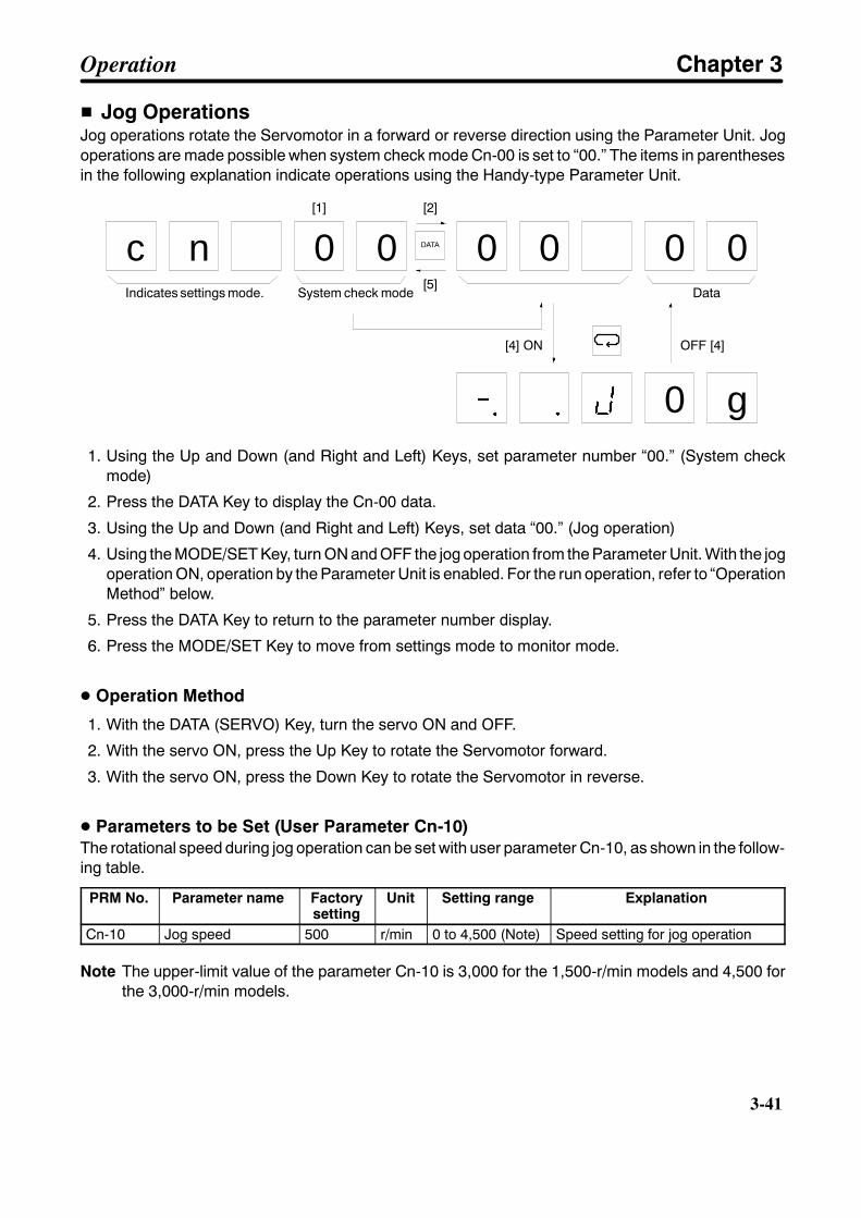
3-41
H Jog OperationsJog operations rotate the Servomotor in a forward or reverse direction using the Parameter Unit. Jogoperations are made possible when system check mode Cn-00 is set to “00.” The items in parenthesesin the following explanation indicate operations using the Handy-type Parameter Unit.
c n 0 0 0 0 0 0
[1] [2]
[5]
[4] ON
Data
OFF [4]
0 g
DATA
Indicates settings mode. System check mode
1. Using the Up and Down (and Right and Left) Keys, set parameter number “00.” (System checkmode)
2. Press the DATA Key to display the Cn-00 data.
3. Using the Up and Down (and Right and Left) Keys, set data “00.” (Jog operation)
4. Using the MODE/SET Key, turn ON and OFF the jog operation from the Parameter Unit. With the jogoperation ON, operation by the Parameter Unit is enabled. For the run operation, refer to “OperationMethod” below.
5. Press the DATA Key to return to the parameter number display.
6. Press the MODE/SET Key to move from settings mode to monitor mode.
D Operation Method
1. With the DATA (SERVO) Key, turn the servo ON and OFF.
2. With the servo ON, press the Up Key to rotate the Servomotor forward.
3. With the servo ON, press the Down Key to rotate the Servomotor in reverse.
D Parameters to be Set (User Parameter Cn-10)The rotational speed during jog operation can be set with user parameter Cn-10, as shown in the follow-ing table.
PRM No. Parameter name Factorysetting
Unit Setting range Explanation
Cn-10 Jog speed 500 r/min 0 to 4,500 (Note) Speed setting for jog operation
Note The upper-limit value of the parameter Cn-10 is 3,000 for the 1,500-r/min models and 4,500 forthe 3,000-r/min models.
Operation Chapter 3
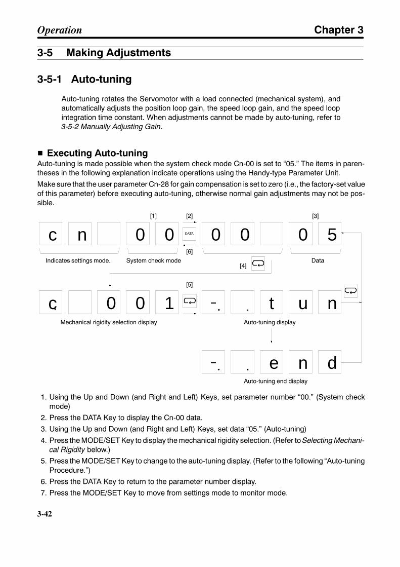
3-42
3-42
3-5 Making Adjustments
3-5-1 Auto-tuning
Auto-tuning rotates the Servomotor with a load connected (mechanical system), andautomatically adjusts the position loop gain, the speed loop gain, and the speed loopintegration time constant. When adjustments cannot be made by auto-tuning, refer to3-5-2 Manually Adjusting Gain.
H Executing Auto-tuningAuto-tuning is made possible when the system check mode Cn-00 is set to “05.” The items in paren-theses in the following explanation indicate operations using the Handy-type Parameter Unit.
Make sure that the user parameter Cn-28 for gain compensation is set to zero (i.e., the factory-set valueof this parameter) before executing auto-tuning, otherwise normal gain adjustments may not be pos-sible.
c
c n 0 0 0 0 0 5
[1] [2]
[6]
[4]Data
[3]
0 0 1 t u n
[5]
e n d
DATA
Indicates settings mode. System check mode
Auto-tuning display
Auto-tuning end display
Mechanical rigidity selection display
1. Using the Up and Down (and Right and Left) Keys, set parameter number “00.” (System checkmode)
2. Press the DATA Key to display the Cn-00 data.
3. Using the Up and Down (and Right and Left) Keys, set data “05.” (Auto-tuning)
4. Press the MODE/SET Key to display the mechanical rigidity selection. (Refer to Selecting Mechani-cal Rigidity below.)
5. Press the MODE/SET Key to change to the auto-tuning display. (Refer to the following “Auto-tuningProcedure.”)
6. Press the DATA Key to return to the parameter number display.
7. Press the MODE/SET Key to move from settings mode to monitor mode.
Operation Chapter 3

3-43
D Selecting Mechanical RigiditySelect the set value to match the rigidity of the mechanical system.
Response Setvalue
Position loop gain(1/s)
Representative applications
Low 001 16 Articulated robots, harmonic drives, chain drives, belt drives,rack and pinion drives, etc.
Low002 28
Articulated robots, harmonic drives, chain drives, belt drives,rack and pinion drives, etc.
Medium 003 40 XY tables, Cartesian-coordinate robots, general-purposemachinery, etc.
High 004 56 Ball screws (direct coupling), feeders, etc.High005 78
Ball screws (direct coupling), feeders, etc.
006 108007 130
Note The response will rise according to a rise in the rigidity of the mechanical system.
D Auto-tuning Procedure1. With the DATA (SERVO) Key, turn the servo ON and OFF.2. While pressing the Up Key, operate the Servomotor three times in the forward direction and adjust
the gain. The auto-tuning will not be complete until the Servomotor has been operated at least threetimes. If the auto-tuning is not complete after three times, then repeat the operation while holdingdown the Up Key. The Servomotor rotation speed should be approximately 1/2 that of the jog speed(Cn-10).
0
1/2 jog speed
Approx. 1.1 s Approx. 0.7 s
3. While pressing the Down Key, adjust the gain in the same way for the reverse direction.4. By executing step 2 or step 3, the user parameter position loop gain (Cn-1A), speed loop gain
(Cn-04), and speed loop integration time constant (Cn-05) will be adjusted automatically. These val-ues will not be changed, however, until the auto-tuning operation has been completed.
5. When the auto-tuning operation is complete, “. end” will be displayed at the Parameter Unit (whilethe Up and Down Keys are being pressed). When the Up and Down Keys are released, “0005” willagain be displayed.
6. If the auto-tuning operation is still not complete even after being executed many times, or if you wishto abort the operation, press the MODE/SET Key. After the MODE/SET Key is pressed, “0005” willagain be displayed.
Note 1. If the auto-tuning operation is not completed, or if there is an inadequate response for the gainthat is adjusted by auto-tuning, refer to 3-5-2 Manually Adjusting Gain and adjust the gainmanually.
Note 2. The auto-tuning will not be complete until the Servomotor has been operated at least threetimes, so pay sufficient attention to the operating range of the machinery. If auto-tuning cannotbe executed within the operating range of the machinery, then adjust the gain manually.
Operation Chapter 3
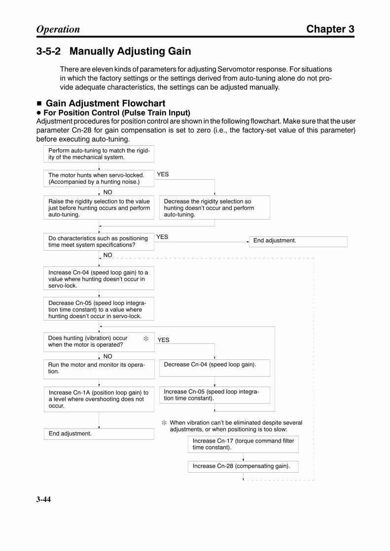
3-44
3-44
3-5-2 Manually Adjusting Gain
There are eleven kinds of parameters for adjusting Servomotor response. For situationsin which the factory settings or the settings derived from auto-tuning alone do not pro-vide adequate characteristics, the settings can be adjusted manually.
H Gain Adjustment FlowchartD For Position Control (Pulse Train Input)Adjustment procedures for position control are shown in the following flowchart. Make sure that the userparameter Cn-28 for gain compensation is set to zero (i.e., the factory-set value of this parameter)before executing auto-tuning.
When vibration can’t be eliminated despite severaladjustments, or when positioning is too slow:
Perform auto-tuning to match the rigid-ity of the mechanical system.
The motor hunts when servo-locked.(Accompanied by a hunting noise.)
Raise the rigidity selection to the valuejust before hunting occurs and performauto-tuning.
Increase Cn-04 (speed loop gain) to avalue where hunting doesn’t occur inservo-lock.
Decrease Cn-05 (speed loop integra-tion time constant) to a value wherehunting doesn’t occur in servo-lock.
Does hunting (vibration) occurwhen the motor is operated?
Run the motor and monitor its opera-tion.
Increase Cn-1A (position loop gain) toa level where overshooting does notoccur.
Decrease the rigidity selection sohunting doesn’t occur and performauto-tuning.
Decrease Cn-04 (speed loop gain).
Increase Cn-05 (speed loop integra-tion time constant).
Increase Cn-17 (torque command filtertime constant).
Increase Cn-28 (compensating gain).
End adjustment.
End adjustment.Do characteristics such as positioningtime meet system specifications?
YES
NO
YES
YES
NO
NO
:
:
Operation Chapter 3
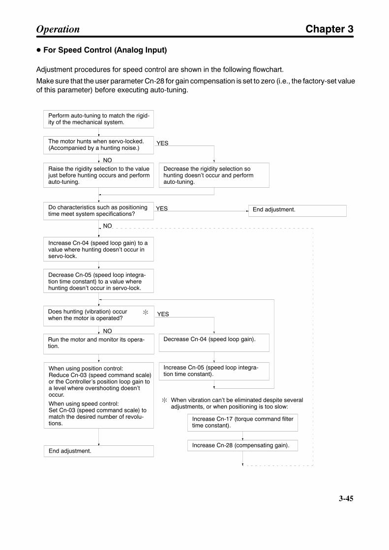
3-45
D For Speed Control (Analog Input)
Adjustment procedures for speed control are shown in the following flowchart.
Make sure that the user parameter Cn-28 for gain compensation is set to zero (i.e., the factory-set valueof this parameter) before executing auto-tuning.
Perform auto-tuning to match the rigid-ity of the mechanical system.
The motor hunts when servo-locked.(Accompanied by a hunting noise.)
Raise the rigidity selection to the valuejust before hunting occurs and performauto-tuning.
Increase Cn-04 (speed loop gain) to avalue where hunting doesn’t occur inservo-lock.
Decrease Cn-05 (speed loop integra-tion time constant) to a value wherehunting doesn’t occur in servo-lock.
Does hunting (vibration) occurwhen the motor is operated?
Run the motor and monitor its opera-tion.
When using position control:Reduce Cn-03 (speed command scale)or the Controller’s position loop gain toa level where overshooting doesn’toccur.
When using speed control:Set Cn-03 (speed command scale) tomatch the desired number of revolu-tions.
Decrease the rigidity selection sohunting doesn’t occur and performauto-tuning.
Decrease Cn-04 (speed loop gain).
Increase Cn-05 (speed loop integra-tion time constant).
Increase Cn-17 (torque command filtertime constant).
Increase Cn-28 (compensating gain).End adjustment.
End adjustment.Do characteristics such as positioningtime meet system specifications?
YES
NO
YES
YES
NO
NO
:
: When vibration can’t be eliminated despite severaladjustments, or when positioning is too slow:
Operation Chapter 3
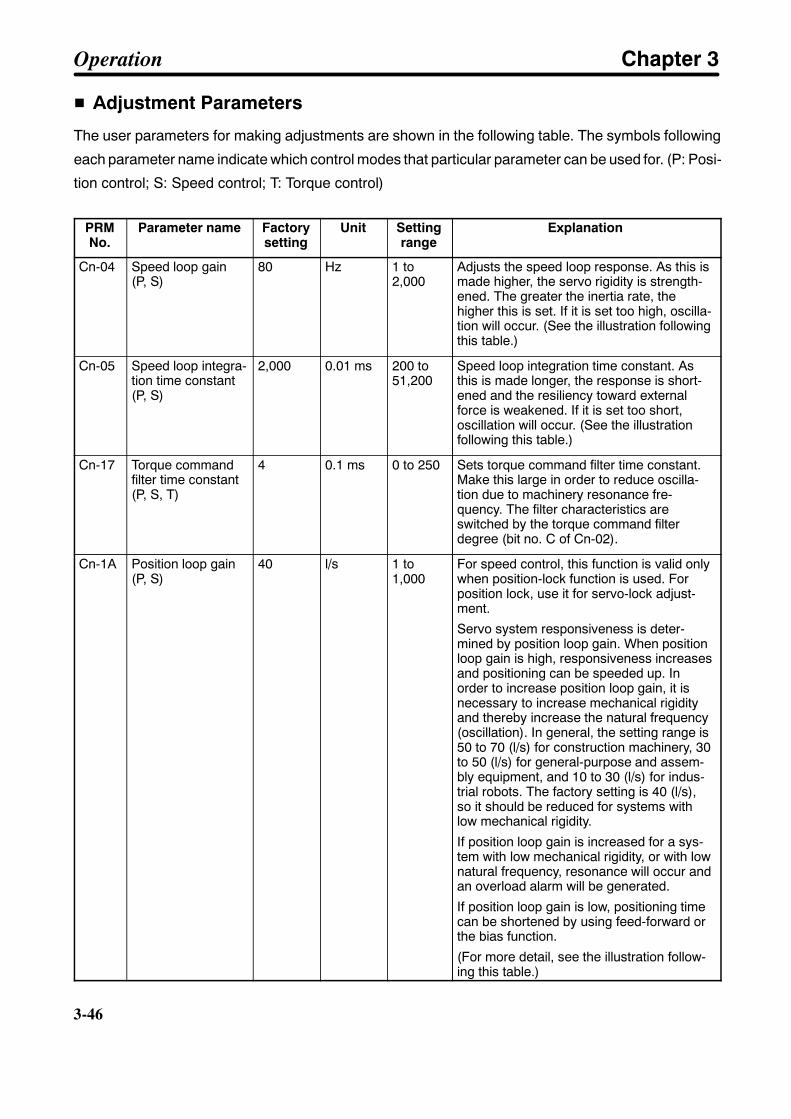
3-46
3-46
H Adjustment Parameters
The user parameters for making adjustments are shown in the following table. The symbols following
each parameter name indicate which control modes that particular parameter can be used for. (P: Posi-
tion control; S: Speed control; T: Torque control)
PRMNo.
Parameter name Factorysetting
Unit Settingrange
Explanation
Cn-04 Speed loop gain(P, S)
80 Hz 1 to2,000
Adjusts the speed loop response. As this ismade higher, the servo rigidity is strength-ened. The greater the inertia rate, thehigher this is set. If it is set too high, oscilla-tion will occur. (See the illustration followingthis table.)
Cn-05 Speed loop integra-tion time constant(P, S)
2,000 0.01 ms 200 to51,200
Speed loop integration time constant. Asthis is made longer, the response is short-ened and the resiliency toward externalforce is weakened. If it is set too short,oscillation will occur. (See the illustrationfollowing this table.)
Cn-17 Torque commandfilter time constant(P, S, T)
4 0.1 ms 0 to 250 Sets torque command filter time constant.Make this large in order to reduce oscilla-tion due to machinery resonance fre-quency. The filter characteristics areswitched by the torque command filterdegree (bit no. C of Cn-02).
Cn-1A Position loop gain(P, S)
40 l/s 1 to1,000
For speed control, this function is valid onlywhen position-lock function is used. Forposition lock, use it for servo-lock adjust-ment.
Servo system responsiveness is deter-mined by position loop gain. When positionloop gain is high, responsiveness increasesand positioning can be speeded up. Inorder to increase position loop gain, it isnecessary to increase mechanical rigidityand thereby increase the natural frequency(oscillation). In general, the setting range is50 to 70 (l/s) for construction machinery, 30to 50 (l/s) for general-purpose and assem-bly equipment, and 10 to 30 (l/s) for indus-trial robots. The factory setting is 40 (l/s),so it should be reduced for systems withlow mechanical rigidity.
If position loop gain is increased for a sys-tem with low mechanical rigidity, or with lownatural frequency, resonance will occur andan overload alarm will be generated.
If position loop gain is low, positioning timecan be shortened by using feed-forward orthe bias function.
(For more detail, see the illustration follow-ing this table.)
Operation Chapter 3
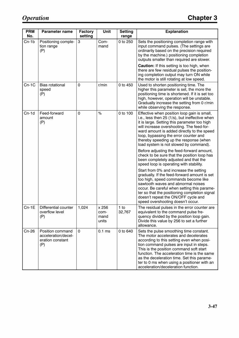
3-47
PRMNo.
ExplanationSettingrange
UnitFactorysetting
Parameter name
Cn-1b Positioning comple-tion range(P)
3 Com-mand
0 to 250 Sets the positioning completion range withinput command pulses. (The settings areordinarily based on the precision requiredby the machine.) positioning completionoutputs smaller than required are slower.
Caution: If this setting is too high, whenthere are few residual pulses the position-ing completion output may turn ON whilethe motor is still rotating at low speed.
Cn-1C Bias rotationalspeed(P)
0 r/min 0 to 450 Used to shorten positioning time. Thehigher this parameter is set, the more thepositioning time is shortened. If it is set toohigh, however, operation will be unstable.Gradually increase the setting from 0 r/minwhile observing the response.
Cn-1d Feed-forwardamount(P)
0 % 0 to 100 Effective when position loop gain is small,i.e., less then 25 (1/s), but ineffective whenit is large. Setting this parameter too highwill increase overshooting. The feed-for-ward amount is added directly to the speedloop, bypassing the error counter andthereby speeding up the response (whenload system is not slowed by command).
Before adjusting the feed-forward amount,check to be sure that the position loop hasbeen completely adjusted and that thespeed loop is operating with stability.
Start from 0% and increase the settinggradually. If the feed-forward amount is settoo high, speed commands become likesawtooth waves and abnormal noisesoccur. Be careful when setting this parame-ter so that the positioning completion signaldoesn’t repeat the ON/OFF cycle andspeed overshooting doesn’t occur.
Cn-1E Differential counteroverflow level(P)
1,024 x 256com-mandunits
1 to32,767
The residual pulses in the error counter areequivalent to the command pulse fre-quency divided by the position loop gain.Divide this value by 256 to set a furtherallowance.
Cn-26 Position commandacceleration/decel-eration constant(P)
0 0.1 ms 0 to 640 Sets the pulse smoothing time constant.The motor accelerates and deceleratesaccording to this setting even when posi-tion command pulses are input in steps.This is the position command soft startfunction. The acceleration time is the sameas the deceleration time. Set this parame-ter to 0 ms when using a positioner with anacceleration/deceleration function.
Operation Chapter 3

3-48
3-48
PRMNo.
ExplanationSettingrange
UnitFactorysetting
Parameter name
Cn-27 Feed-forward com-mand filter(P)
0 0.1 ms 0 to 640 Sets the filter so that the feed-forwardamount is not added suddenly when posi-tion command pulses are input in steps.
Cn-28 Compensating gain(P, S)
0 --- 0 to 100 Decreases the speed loop gain by the setvalue when a large torque is output due toacceleration, deceleration, etc. Increasingthe set value reduces motor oscillation, andpositioning time can be shortened. If theset value is too large, a follow-up delay willoccur for acceleration and deceleration.A compensation gain adjustment is pos-sible only after adjusting the speed loopgain with Cn-04 and the speed loop integraltime constant with Cn-05.The upper-limit value of the compensationgain may be 100 or less according to thespeed loop gain set with Cn-04 and thespeed loop integral time constant set withCn-05, in which case an error will result ifthe compensation gain is set to a valueexceeding the upper-limit value.Make sure that Cn-28 is set to zero beforeexecuting auto-tuning, otherwise normalgain adjustments may not be possible.
D Adjusting Speed Loop Gain (Cn-04)When the speed loop gain is manipulated, the response is as shown in the diagram below.
Motor speed(speed monitor)
Overshoots when speed loop gain ishigh. (Oscillates when gain is too high.)
When speed loop gain is low.
Time
Operation Chapter 3
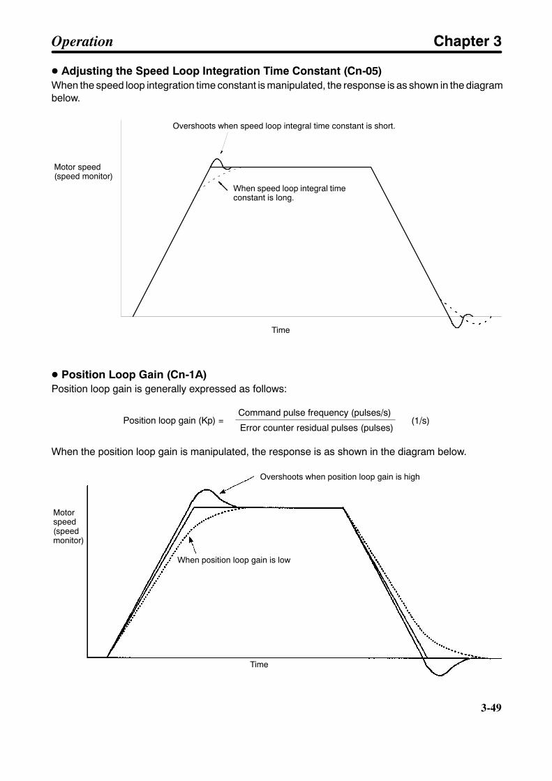
3-49
D Adjusting the Speed Loop Integration Time Constant (Cn-05)When the speed loop integration time constant is manipulated, the response is as shown in the diagrambelow.
Motor speed(speed monitor)
Time
Overshoots when speed loop integral time constant is short.
When speed loop integral timeconstant is long.
D Position Loop Gain (Cn-1A)Position loop gain is generally expressed as follows:
Position loop gain (Kp) =Command pulse frequency (pulses/s)
Error counter residual pulses (pulses)(1/s)
When the position loop gain is manipulated, the response is as shown in the diagram below.
Motorspeed(speedmonitor)
Overshoots when position loop gain is high
When position loop gain is low
Time
Operation Chapter 3
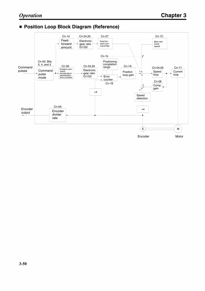
3-50
3-50
H Position Loop Block Diagram (Reference)
Commandpulses
Encoderoutput
Commandpulsemode
Position com-mandAcceleration/decelerationtime constant
Electronicgear ratioG1/G2
Feed-forwardamount
Feed-for-ward com-mand filter
Bias rota-tionalspeed
Positioningcompletionrange
Errorcounter
Cn-02: Bits5, 4, and 3
Positionloop gain
Encoderdividerrate
Encoder Motor
Speedloop
Currentloop
Speeddetection
ME
Cn-24,25 Cn-04,05
Cn-24,25
Cn-17
Cn-0A
Comp.gain
Cn-28+
+
Cn-1d Cn-27
Cn-26 Cn-1A
Cn-1E
Cn-1b
Electronicgear ratioG1/G2
Cn-1C
×4
×4
Operation Chapter 3
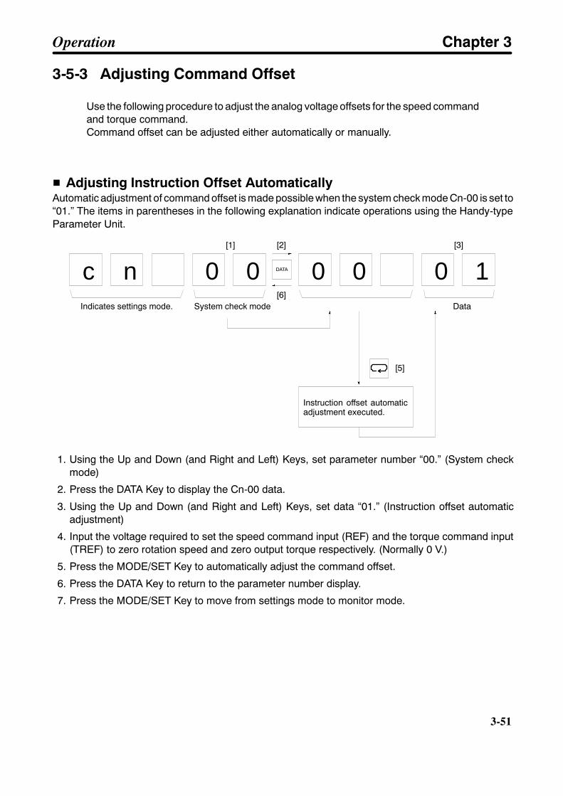
3-51
3-5-3 Adjusting Command Offset
Use the following procedure to adjust the analog voltage offsets for the speed commandand torque command.Command offset can be adjusted either automatically or manually.
H Adjusting Instruction Offset AutomaticallyAutomatic adjustment of command offset is made possible when the system check mode Cn-00 is set to“01.” The items in parentheses in the following explanation indicate operations using the Handy-typeParameter Unit.
c n 0 0 0 0 0 1
[1] [2]
[6]Data
[3]
[5]
DATA
Indicates settings mode. System check mode
Instruction offset automaticadjustment executed.
1. Using the Up and Down (and Right and Left) Keys, set parameter number “00.” (System checkmode)
2. Press the DATA Key to display the Cn-00 data.
3. Using the Up and Down (and Right and Left) Keys, set data “01.” (Instruction offset automaticadjustment)
4. Input the voltage required to set the speed command input (REF) and the torque command input(TREF) to zero rotation speed and zero output torque respectively. (Normally 0 V.)
5. Press the MODE/SET Key to automatically adjust the command offset.
6. Press the DATA Key to return to the parameter number display.
7. Press the MODE/SET Key to move from settings mode to monitor mode.
Operation Chapter 3
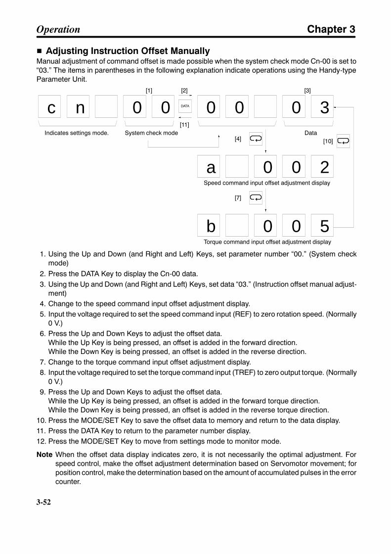
3-52
3-52
H Adjusting Instruction Offset ManuallyManual adjustment of command offset is made possible when the system check mode Cn-00 is set to“03.” The items in parentheses in the following explanation indicate operations using the Handy-typeParameter Unit.
c n 0 0 0 0 0 3
Data
a 0 0 2
DATA
Indicates settings mode. System check mode
Speed command input offset adjustment display
b 0 0 5Torque command input offset adjustment display
[1] [2] [3]
[4]
[7]
[10]
[11]
1. Using the Up and Down (and Right and Left) Keys, set parameter number “00.” (System checkmode)
2. Press the DATA Key to display the Cn-00 data.3. Using the Up and Down (and Right and Left) Keys, set data “03.” (Instruction offset manual adjust-
ment)4. Change to the speed command input offset adjustment display.5. Input the voltage required to set the speed command input (REF) to zero rotation speed. (Normally
0 V.)6. Press the Up and Down Keys to adjust the offset data.
While the Up Key is being pressed, an offset is added in the forward direction.While the Down Key is being pressed, an offset is added in the reverse direction.
7. Change to the torque command input offset adjustment display.8. Input the voltage required to set the torque command input (TREF) to zero output torque. (Normally
0 V.)9. Press the Up and Down Keys to adjust the offset data.
While the Up Key is being pressed, an offset is added in the forward torque direction.While the Down Key is being pressed, an offset is added in the reverse torque direction.
10. Press the MODE/SET Key to save the offset data to memory and return to the data display.11. Press the DATA Key to return to the parameter number display.12. Press the MODE/SET Key to move from settings mode to monitor mode.
Note When the offset data display indicates zero, it is not necessarily the optimal adjustment. Forspeed control, make the offset adjustment determination based on Servomotor movement; forposition control, make the determination based on the amount of accumulated pulses in the errorcounter.
Operation Chapter 3

3-53
3-6 Regenerative Energy Absorption
3-6-1 Calculating Regenerative Energy
Regenerative energy produced at times such as Servomotor deceleration is absorbedby the Servo Driver’s internal capacitors, thereby preventing an increase in DC voltage.If the regenerative energy from the Servomotor becomes too large, however, an over-voltage error will occur. In such cases, it is necessary to reduce the regenerative energyby taking an action such as changing operation patterns.
Regenerative energy is produced when the direction of Servomotor rotation or output torque isreversed. The methods for calculating regenerative energy for the horizontal and vertical shafts areexplained below.
H Horizontal Axle+N1
--N2
Eg1
TD1
t1
Eg2
TD2
t2T
Motor operation
Motor outputtorque
Note In the output torque graph, acceleration in the positive side (rising) is shown as positive, andacceleration in the negative side (falling) is shown as negative.The regenerative energy for each section can be found by means of the following formulas:
Eg1 = 1/2 S N1 S TD1 S t1 S 1.027 × 10--2 [J]Eg2 = 1/2 S N2 S TD2 S t2 S 1.027 × 10--2 [J]
N1, N2: Rotation speed at beginning of deceleration [r/min]TD1, TD2: Deceleration torque [kgf S cm]t1, t2: Deceleration time [s]
Note There is some loss due to winding resistance, so the actual regenerative energy will be approxi-mately 90% of the figure derived by the formula.
Operation Chapter 3
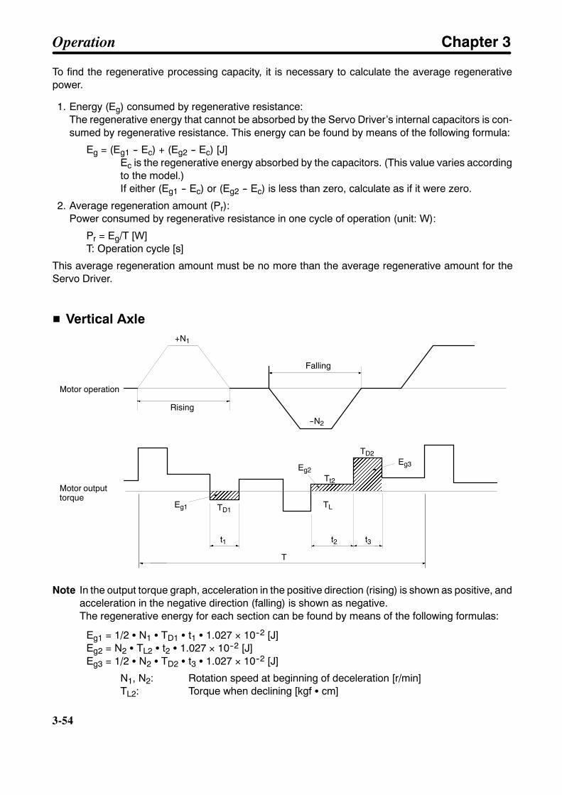
3-54
3-54
To find the regenerative processing capacity, it is necessary to calculate the average regenerativepower.
1. Energy (Eg) consumed by regenerative resistance:The regenerative energy that cannot be absorbed by the Servo Driver’s internal capacitors is con-sumed by regenerative resistance. This energy can be found by means of the following formula:
Eg = (Eg1 -- Ec) + (Eg2 -- Ec) [J]Ec is the regenerative energy absorbed by the capacitors. (This value varies accordingto the model.)If either (Eg1 -- Ec) or (Eg2 -- Ec) is less than zero, calculate as if it were zero.
2. Average regeneration amount (Pr):Power consumed by regenerative resistance in one cycle of operation (unit: W):
Pr = Eg/T [W]T: Operation cycle [s]
This average regeneration amount must be no more than the average regenerative amount for theServo Driver.
H Vertical Axle+N1
--N2
Motor operation
Rising
Falling
Motor outputtorque
TLEg1 TD1
t1
Eg2
TD2
t2
T
Tt2
Eg3
t3
Note In the output torque graph, acceleration in the positive direction (rising) is shown as positive, andacceleration in the negative direction (falling) is shown as negative.The regenerative energy for each section can be found by means of the following formulas:
Eg1 = 1/2 S N1 S TD1 S t1 S 1.027 × 10--2 [J]Eg2 = N2 S TL2 S t2 S 1.027 × 10--2 [J]Eg3 = 1/2 S N2 S TD2 S t3 S 1.027 × 10--2 [J]
N1, N2: Rotation speed at beginning of deceleration [r/min]TL2: Torque when declining [kgf S cm]
Operation Chapter 3

3-55
TD1, TD2: Deceleration torque [kgf S cm]t1, t3: Deceleration time [s]t2: Travel time equivalent to torque when declining [s]
Note There is some loss due to winding resistance, so the actual regenerative energy will be approxi-mately 90% of the figure derived by the formula.
To find the regenerative processing capacity, it is necessary to calculate the average regenerativepower.
1. Energy (Eg) consumed by regenerative resistance:The regenerative energy that cannot be absorbed by the Servo Driver’s internal capacitors is con-sumed by regenerative resistance. This energy can be found by means of the following formula:
Eg = (Eg1 -- Ec) + (Eg2+ Eg3 -- Ec) [J]Ec is the regenerative energy absorbed by the capacitors. (This value varies accordingto the model.)If either (Eg1 -- Ec) or (Eg2+ Eg3 -- Ec) is less than zero, calculate as if it were zero.
2. Average regeneration amount (Pr):Power consumed by regenerative resistance in one cycle of operation (unit: W):
Pr = Eg/T [W]T: Operation cycle [s]
This average regeneration amount must be no more than the average regenerative amount for theServo Driver.
3-6-2 Servo Driver Absorbable Regenerative Energy
H Regenerative Energy Absorbed InternallyThe Servo Driver absorbs regenerative energy by means of an internal capacitor. If there is more regen-erative energy than can be absorbed by the capacitor, an overvoltage error will be generated and opera-tion cannot continue. The amounts of regenerative energy that can be absorbed by the various ServoDrivers alone are shown in the tables below. If regenerative energy exceeding these values is pro-duced, take the following measures.
• Lower the operating rotation speed. (The regenerative energy is proportional to the square of therotation speed.)
• Lengthen the deceleration time. (Reduce the amount of regenerative energy per unit time.)
• Lengthen the operating cycle (i.e., the cycle time). (Reduce the average regenerative power.)
Servo Drivers Absorptive regeneration energyEc (J)
Average absorbable regenerative energy(W)
R88D-UT24V 24.3 28R88D-UT40V/H-E 24.3 28R88D-UT60V/H-E 64.3 28R88D-UT80V/H-E 64.3 28R88D-UT110H-E 107 56
Operation Chapter 3

3-56
3-56
Servo Drivers requir-ing external regenera-
tive resistors
Absorptive regeneration energyEc (J)
R88D-UT24V-RG 24.3R88D-UT40V-RG 24.3R88D-UT60V-RG 64.3R88D-UT80V-RG 64.3R88D-UT110V 119R88D-UT160V/H-E 119
Note 1. The Servo Drivers requiring external regenerative resistors do no have built-in regenerativeresistors. Be sure to install Regenerative Resistors that correspond to the amount of regen-erative energy.
Note 2. The input voltage is the value at 200 VAC. As the input voltage is increased, the amount ofregenerative energy that can be absorbed is decreased.
3-6-3 Absorption of Regenerative Energy by Servo Driverswith External Regenerative Resistors
If there is excessive regenerative energy that cannot be absorbed by the Servo Driver, use a ServoDriver model to which external regenerative resistors can be connected. An appropriate number ofexternal regenerative resistors must be connected between the +1 and B terminals of the Servo Driver.Do not connect external regenerative resistors to any other terminals of the Servo Driver, otherwise theServo Driver may be damaged. The temperature of the external regenerative resistors rises by approxi-mately 120°C. Be sure to keep them away from any device or wiring that may be affected by heat. Besure to attach proper heat sinks to the external regenerative resistors before use.
H External Regenerative Resistor
D ModelModel Resistance Nominal
capacityAbsorption ofregenerative
energy at 120°Ctemperature rise
Heat radiatingcondition
Thermal switchoutput
specification
R88A-RR22047S 47Ω±5% 220 W 70 W t1.0 x j350(SPCC)
Operatingtemperature:170°C
D Combinations of External Regenerative ResistorsRegenerative absorption capacity
70 W 280 W 1120 WCombination
Note Make sure to combine external regenerative resistors so that their regeneration absorbing capac-ity exceeds the average regenerative power (Pr).
Operation Chapter 3

3-57
D Dimensions
Thermal switch output
H Wiring of External Regenerative ResistorThe external regenerative resistor must be connected between + and B terminals (or between +1 and Bterminals for the R88D-UT110V). With the R88D-UT160H-E, connect the resistor between P1 and Bterminals.
External regenerative resistor
Note Like the ALM output of the Regeneration Unit, the power source of thermal switch output shouldturn power off when the contact is open. Refer to 2-3-4 Peripheral Device Connection Examples.
Operation Chapter 3
Chapter 4
Application4-1 Absolute Encoder Setup and Battery Changes
4-2 Using Displays
4-3 Using Monitor Output
4-4 Protective and Diagnostic Functions
4-5 Periodic Maintenance
4
!
!
!
!
!
!
4-2
4-2
Operation and Adjustment PrecautionsCaution Check the newly set parameters for proper execution before actually running them.
Not doing so may result in equipment damage.
Caution Do not make any extreme adjustments or setting changes. Doing so may result inunstable operation and injury.
Caution Separate the Servomotor from the machine, check for proper operation, and thenconnect to the machine. Not doing so may cause injury.
Caution When an alarm occurs, remove the cause, reset the alarm after confirming safety,and then resume operation. Not doing so may result in injury.
Caution Do not come close to the machine immediately after resetting momentary powerinterruption to avoid an unexpected restart. (Take appropriate measures to securesafety against an unexpected restart.) Doing so may result in injury.
Caution Do not use the built-in brake of the Servomotor for ordinary braking. Doing so mayresult in malfunction.
Application Chapter 4
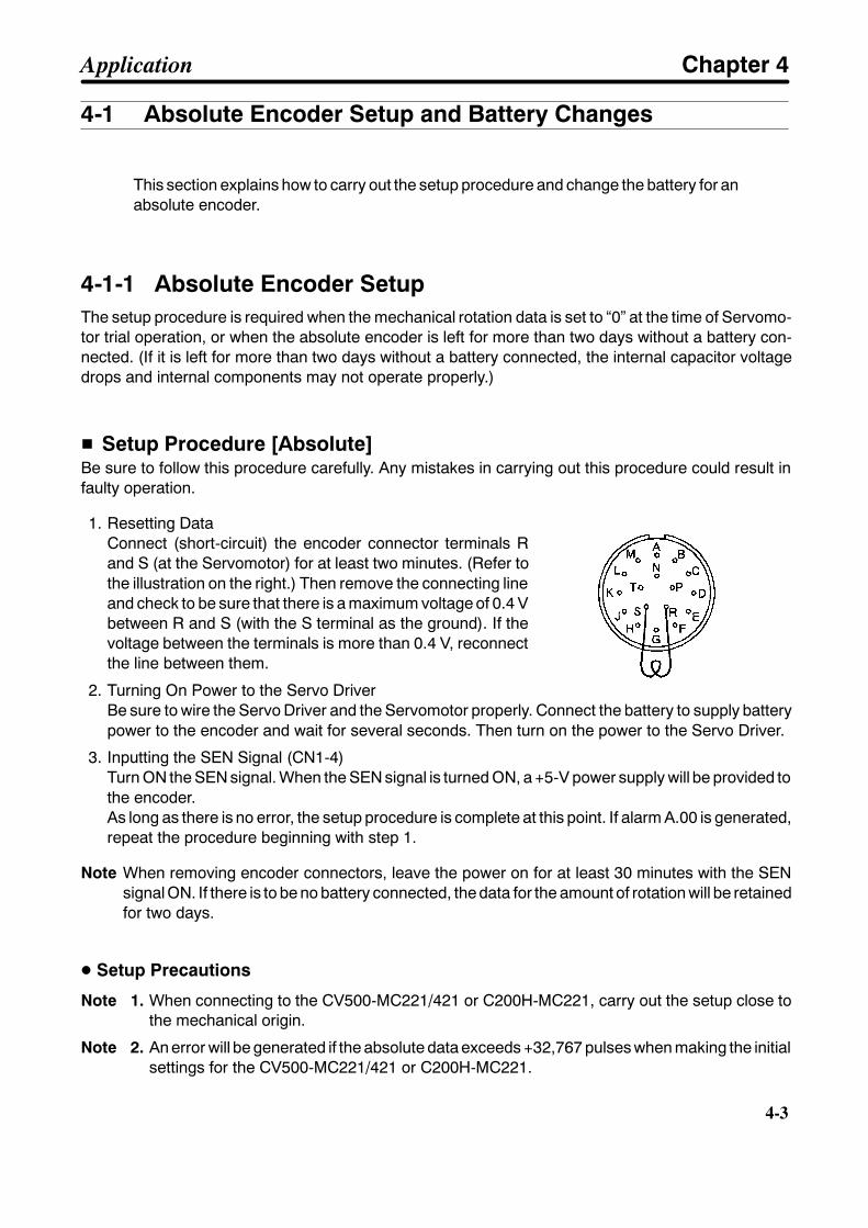
4-3
4-1 Absolute Encoder Setup and Battery Changes
This section explains how to carry out the setup procedure and change the battery for anabsolute encoder.
4-1-1 Absolute Encoder SetupThe setup procedure is required when the mechanical rotation data is set to “0” at the time of Servomo-tor trial operation, or when the absolute encoder is left for more than two days without a battery con-nected. (If it is left for more than two days without a battery connected, the internal capacitor voltagedrops and internal components may not operate properly.)
H Setup Procedure [Absolute]Be sure to follow this procedure carefully. Any mistakes in carrying out this procedure could result infaulty operation.
1. Resetting DataConnect (short-circuit) the encoder connector terminals Rand S (at the Servomotor) for at least two minutes. (Refer tothe illustration on the right.) Then remove the connecting lineand check to be sure that there is a maximum voltage of 0.4 Vbetween R and S (with the S terminal as the ground). If thevoltage between the terminals is more than 0.4 V, reconnectthe line between them.
2. Turning On Power to the Servo DriverBe sure to wire the Servo Driver and the Servomotor properly. Connect the battery to supply batterypower to the encoder and wait for several seconds. Then turn on the power to the Servo Driver.
3. Inputting the SEN Signal (CN1-4)Turn ON the SEN signal. When the SEN signal is turned ON, a +5-V power supply will be provided tothe encoder.As long as there is no error, the setup procedure is complete at this point. If alarm A.00 is generated,repeat the procedure beginning with step 1.
Note When removing encoder connectors, leave the power on for at least 30 minutes with the SENsignal ON. If there is to be no battery connected, the data for the amount of rotation will be retainedfor two days.
D Setup Precautions
Note 1. When connecting to the CV500-MC221/421 or C200H-MC221, carry out the setup close tothe mechanical origin.
Note 2. An error will be generated if the absolute data exceeds +32,767 pulses when making the initialsettings for the CV500-MC221/421 or C200H-MC221.
Application Chapter 4

4-4
4-4
4-1-2 Replacing Batteries [Absolute]
H Lithium BatteriesBe sure to use a battery so that position data will be retained even in case of a power interruption for theabsolute encoder. The following batteries are recommended.
Maker Model Voltage Electrical capacity RemarksToshiba Corp. ER6V 3.6 V 2,000 mA • h One/Servo Driver
Service life: Approx. 10 yearsHitachi Maxell, Ltd. ER6 3.6 V 2,050 mA • h One/Servo Driver
Service life: Approx. 10 yearsOMRON (made byHitachi Maxell, Ltd.)
C500-BAT08(ER17/33)
3.6 V 1,650 mA • h One/Servo DriverService life: Approx. 7 years
Note If the Servo Driver’s internal power supply is turned OFF, the battery voltage will not be monitored.Be careful to ensure that the voltage does not fall below 2.8 V. If required, install a battery voltagedrop detection circuit or monitor in the system.
H Battery Replacement MethodThe following procedure can be used to replace the battery without losing the encoder’s rotation data.
1. Turn on the power to the Servo Driver and turn ON the SEN signal, and leave them for at least 30minutes to charge the encoder’s internal capacitors.
2. Replace the battery. Connect the battery between the Servo Driver’s control I/O connector (CN1)pin nos. 21 and 22.
21: BAT Backup battery + input (Connect a 2.8- to 4.5-VDC battery.)22: BATGND Backup battery -- input (ground for backup battery)
The battery can be replaced with the power either turned on or off.
Note 1. After step number 1 above has been implemented, the encoder will operate properly for twodays even with the battery removed.
Note 2. When replacing the battery, be careful not to short-circuit across the battery’s plus and minusterminals.
Note 3. When cutting battery lead lines, cut plus and minus lines separately. If they are cut simulta-neously, they may short circuit and cause sparks.
Note 4. Dispose batteries according to the specified methods. Never throw the battery into a fire,otherwise it may explode.
Application Chapter 4

!
4-5
4-2 Using Displays
OMRON U-series AC Servomotors have unique servo software that enables quantita-tive monitoring in real time, on digital displays, of changes in a variety of characteristics.Use these displays for checking the various characteristics during operation.
4-2-1 Display FunctionsH Servo Driver DisplaysThere are three LED indicators on the Servo Driver itself. One is for the power supply, one is for alarms,and the other is a charge indicator.
Symbol Name Color FunctionPOWER Power supply
indicatorGreen Lit when control power supply is normal.
ALARM Alarm indicator Red Lit when error occurs.CHARGE Charge indicator Red Lit when main-circuit power supply is charging.
Power supply indicator
Alarm indicator
Charge indicator
R88D-UT40H
D Charge Indicator (CHARGE) FunctionThe charge indicator lights when the voltage is added to the main-circuit power supply capacitors in theServo Driver.
Caution Even after the AC power supply has been interrupted, the charge lamp remains lit toindicate that voltage is remaining. Wait until this indicator turns off before touchingthe terminal block for inspection or any other purpose. Touching the terminal blockwhile this indicator is lit can result in electrical shock.
Application Chapter 4

4-6
4-6
H Parameter Unit DisplaysWhen a Parameter Unit is connected, monitoring can be conducted by means of a 5-digit 7-segmentLED.
R88A-PR02U Handy Type R88A-PR03U Mounted Type
H Parameter Unit Key FunctionsThe contents displayed by the Parameter Unit can be changed by key operations.
Handy typeR88A-PR02U
Mounted typeR88A-PR03U
Function
RESET + Alarm reset
Mode switching; data memory
SERVO DATAServo ON/OFF during jog operations
DATA DATASwitching between parameter displayand data display; data memoryIncrements parameter numbers anddata values.Decrements parameter numbers anddata values.Left shift for operation digits
Right shift for operation digits
Application Chapter 4
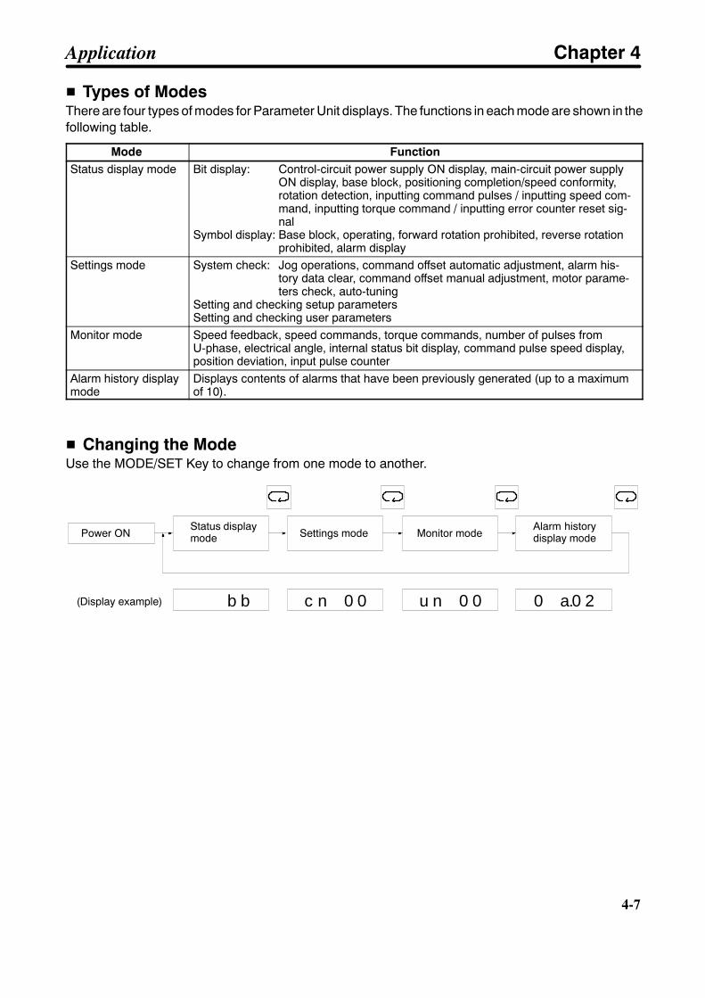
4-7
H Types of ModesThere are four types of modes for Parameter Unit displays. The functions in each mode are shown in thefollowing table.
Mode FunctionStatus display mode Bit display: Control-circuit power supply ON display, main-circuit power supply
ON display, base block, positioning completion/speed conformity,rotation detection, inputting command pulses / inputting speed com-mand, inputting torque command / inputting error counter reset sig-nal
Symbol display: Base block, operating, forward rotation prohibited, reverse rotationprohibited, alarm display
Settings mode System check: Jog operations, command offset automatic adjustment, alarm his-tory data clear, command offset manual adjustment, motor parame-ters check, auto-tuning
Setting and checking setup parametersSetting and checking user parameters
Monitor mode Speed feedback, speed commands, torque commands, number of pulses fromU-phase, electrical angle, internal status bit display, command pulse speed display,position deviation, input pulse counter
Alarm history displaymode
Displays contents of alarms that have been previously generated (up to a maximumof 10).
H Changing the ModeUse the MODE/SET Key to change from one mode to another.
b b c n 0 0 u n 0 0 0 a.0 2
Power ONStatus displaymode Settings mode Monitor mode
Alarm historydisplay mode
(Display example)
Application Chapter 4
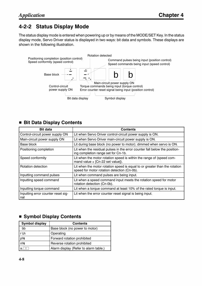
4-8
4-8
4-2-2 Status Display ModeThe status display mode is entered when powering up or by means of the MODE/SET Key. In the statusdisplay mode, Servo Driver status is displayed in two ways: bit data and symbols. These displays areshown in the following illustration.
b b
Rotation detectedPositioning completion (position control)Speed conformity (speed control)
Speed commands being input (speed control)
Base block
Control-circuitpower supply ON
Torque commands being input (torque control)
Bit data display Symbol display
Command pulses being input (position control)
Error counter reset signal being input (position control)
Main-circuit power supply ON
H Bit Data Display ContentsBit data Contents
Control-circuit power supply ON Lit when Servo Driver control-circuit power supply is ON.Main-circuit power supply ON Lit when Servo Driver main-circuit power supply is ON.Base block Lit during base block (no power to motor); dimmed when servo is ON.Positioning completion Lit when the residual pulses in the error counter fall below the position-
ing completion range set for Cn-1b.Speed conformity Lit when the motor rotation speed is within the range of (speed com-
mand value ± [Cn-22 set value]).Rotation detection Lit when the motor rotation speed is equal to or greater than the rotation
speed for motor rotation detection (Cn-0b).Inputting command pulses Lit when command pulses are being input.Inputting speed command Lit when a speed command input meets the rotation speed for motor
rotation detection (Cn-0b).Inputting torque command Lit when a torque command at least 10% of the rated torque is input.Inputting error counter reset sig-nal
Lit when the error counter reset signal is being input.
H Symbol Display ContentsSymbol display Contentsbb Base block (no power to motor)rUn Operatingp%t Forward rotation prohibitedn%t Reverse rotation prohibiteda.jj Alarm display (Refer to alarm table.)
Application Chapter 4
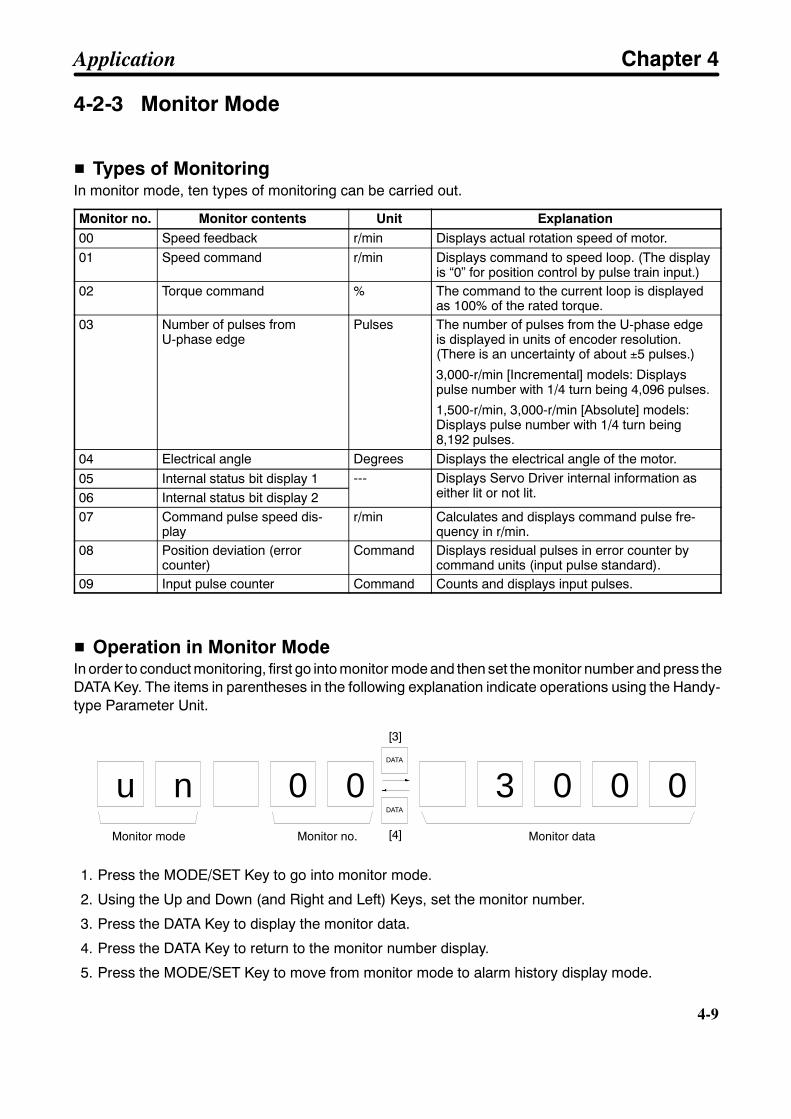
4-9
4-2-3 Monitor Mode
H Types of MonitoringIn monitor mode, ten types of monitoring can be carried out.
Monitor no. Monitor contents Unit Explanation00 Speed feedback r/min Displays actual rotation speed of motor.01 Speed command r/min Displays command to speed loop. (The display
is “0” for position control by pulse train input.)02 Torque command % The command to the current loop is displayed
as 100% of the rated torque.03 Number of pulses from
U-phase edgePulses The number of pulses from the U-phase edge
is displayed in units of encoder resolution.(There is an uncertainty of about ±5 pulses.)
3,000-r/min [Incremental] models: Displayspulse number with 1/4 turn being 4,096 pulses.
1,500-r/min, 3,000-r/min [Absolute] models:Displays pulse number with 1/4 turn being8,192 pulses.
04 Electrical angle Degrees Displays the electrical angle of the motor.05 Internal status bit display 1 --- Displays Servo Driver internal information as
either lit or not lit.06 Internal status bit display 2--- Displays Servo Driver internal information as
either lit or not lit.
07 Command pulse speed dis-play
r/min Calculates and displays command pulse fre-quency in r/min.
08 Position deviation (errorcounter)
Command Displays residual pulses in error counter bycommand units (input pulse standard).
09 Input pulse counter Command Counts and displays input pulses.
H Operation in Monitor ModeIn order to conduct monitoring, first go into monitor mode and then set the monitor number and press theDATA Key. The items in parentheses in the following explanation indicate operations using the Handy-type Parameter Unit.
u n 0 0 3 0 0 0
[3]
[4]
DATA
DATA
Monitor mode Monitor no. Monitor data
1. Press the MODE/SET Key to go into monitor mode.
2. Using the Up and Down (and Right and Left) Keys, set the monitor number.
3. Press the DATA Key to display the monitor data.
4. Press the DATA Key to return to the monitor number display.
5. Press the MODE/SET Key to move from monitor mode to alarm history display mode.
Application Chapter 4
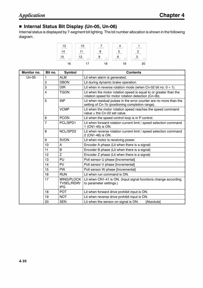
4-10
4-10
H Internal Status Bit Display (Un-05, Un-06)Internal status is displayed by 7-segment bit lighting. The bit number allocation is shown in the followingdiagram.
15
14
13
16
12
11
10
17
9
8
7
18
6
5
4
19
3
2
1
20
Monitor no. Bit no. Symbol ContentsUn-05 1 ALM Lit when alarm is generated.Un-05
2 DBON Lit during dynamic brake operation.3 DIR Lit when in reverse rotation mode (when Cn-02 bit no. 0 = 1).4 TGON Lit when the motor rotation speed is equal to or greater than the
rotation speed for motor rotation detection (Cn-0b).5 INP Lit when residual pulses in the error counter are no more than the
setting of Cn-1b (positioning completion range).VCMP Lit when the motor rotation speed reaches the speed command
value ± the Cn-22 set value.6 PCON Lit when the speed control loop is in P control.7 PCL/SPD1 Lit when forward rotation current limit / speed selection command
1 (CN1-45) is ON.8 NCL/SPD2 Lit when reverse rotation current limit / speed selection command
2 (CN1-46) is ON.9 SVON Lit when motor is receiving power.10 A Encoder A phase (Lit when there is a signal)11 B Encoder B phase (Lit when there is a signal)12 Z Encoder Z phase (Lit when there is a signal)13 PU Poll sensor U phase [Incremental]14 PV Poll sensor V phase [Incremental]15 PW Poll sensor W phase [Incremental]16 RUN Lit when run command is ON.17 MING/PLOCK
TVSEL/RDIR/IPG
Lit when CN1-41 is ON. (Input signal functions change accordingto parameter settings.)
18 POT Lit when forward drive prohibit input is ON.19 NOT Lit when reverse drive prohibit input is ON.20 SEN Lit when the sensor-on signal is ON. [Absolute]
Application Chapter 4
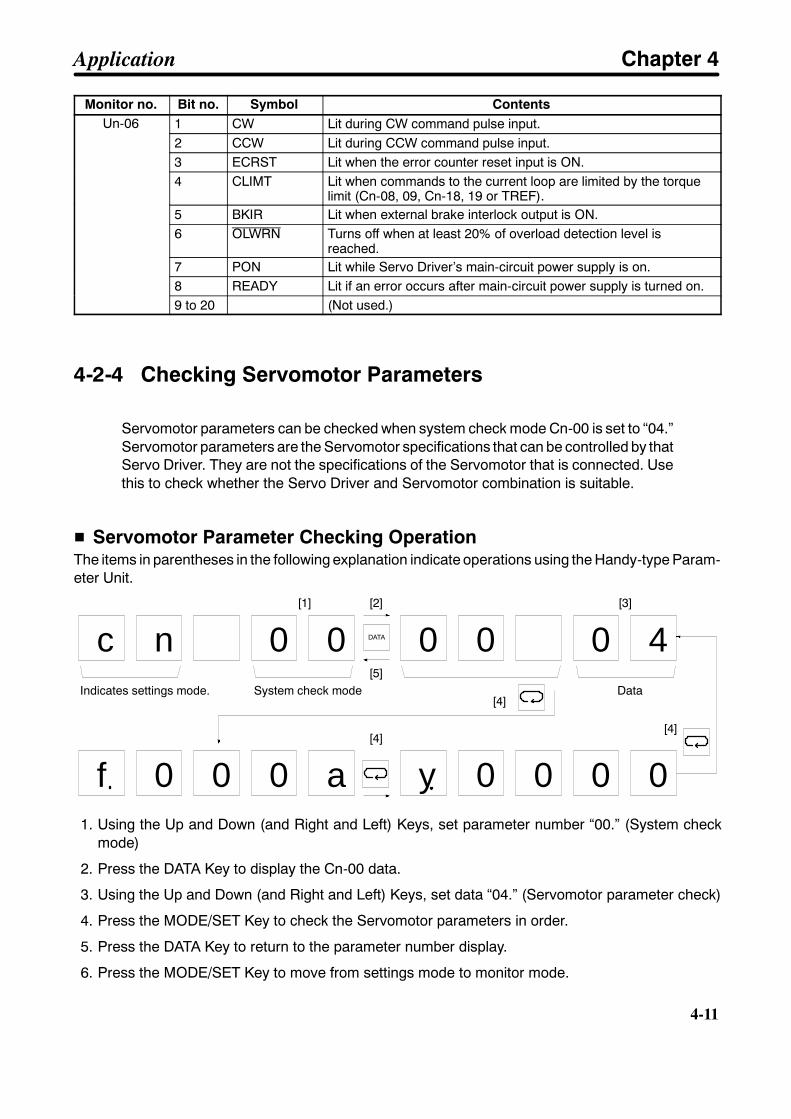
4-11
Monitor no. ContentsSymbolBit no.Un-06 1 CW Lit during CW command pulse input.Un-06
2 CCW Lit during CCW command pulse input.3 ECRST Lit when the error counter reset input is ON.4 CLIMT Lit when commands to the current loop are limited by the torque
limit (Cn-08, 09, Cn-18, 19 or TREF).5 BKIR Lit when external brake interlock output is ON.6 OLWRN Turns off when at least 20% of overload detection level is
reached.7 PON Lit while Servo Driver’s main-circuit power supply is on.8 READY Lit if an error occurs after main-circuit power supply is turned on.9 to 20 (Not used.)
4-2-4 Checking Servomotor Parameters
Servomotor parameters can be checked when system check mode Cn-00 is set to “04.”Servomotor parameters are the Servomotor specifications that can be controlled by thatServo Driver. They are not the specifications of the Servomotor that is connected. Usethis to check whether the Servo Driver and Servomotor combination is suitable.
H Servomotor Parameter Checking OperationThe items in parentheses in the following explanation indicate operations using the Handy-type Param-eter Unit.
0yf
c n 0 0 0 0 0 4
[1] [2]
[5]
[4]Data
[3]
0 0 0 a 0 0 0
[4][4]
DATA
Indicates settings mode. System check mode
1. Using the Up and Down (and Right and Left) Keys, set parameter number “00.” (System checkmode)
2. Press the DATA Key to display the Cn-00 data.
3. Using the Up and Down (and Right and Left) Keys, set data “04.” (Servomotor parameter check)
4. Press the MODE/SET Key to check the Servomotor parameters in order.
5. Press the DATA Key to return to the parameter number display.
6. Press the MODE/SET Key to move from settings mode to monitor mode.
Application Chapter 4
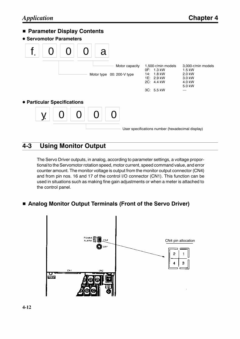
4-12
4-12
H Parameter Display ContentsD Servomotor Parameters
f 0 0 0 aMotor capacity 1,500-r/min models 3,000-r/min models
0F: 1.3 kW 1.5 kW14: 1.8 kW 2.0 kW1E: 2.9 kW 3.0 kW2C: 4.4 kW 4.0 kW
5.0 kW3C: 5.5 kW ---
Motor type 00: 200-V type
D Particular Specifications
0y 0 0 0User specifications number (hexadecimal display)
4-3 Using Monitor Output
The Servo Driver outputs, in analog, according to parameter settings, a voltage propor-tional to the Servomotor rotation speed, motor current, speed command value, and errorcounter amount. The monitor voltage is output from the monitor output connector (CN4)and from pin nos. 16 and 17 of the control I/O connector (CN1). This function can beused in situations such as making fine gain adjustments or when a meter is attached tothe control panel.
H Analog Monitor Output Terminals (Front of the Servo Driver)
CN4 pin allocation
Application Chapter 4

4-13
H Monitor Output Circuit
47 Ω
47 Ω
CN4-2
CN1-16
CN4-1
CN1-17
CN4-3,4
CN1-1
AM terminalCurrent monitor or speed command monitor /command pulse speed monitor
NM terminalSpeed monitor or error counter monitor
Ground
H Setup Parameter SettingsAnalog monitor output contents can be selected by means of bit nos. 6 and 7 of setup parameter no. 2(Cn-02). The settings are shown in the following table.
Item Bit no. Factorysetting
Setting Explanation
Monitor switch 1 6 0 0 Takes AM (CN1-16 and CN4-2) analog monitoroutput as current monitor output.
1 Takes AM (CN1-16 and CN4-2) analog monitoroutput as speed command monitor output (for speedcontrol) or command pulse speed monitor output (forposition control). Not valid for torque control (i.e., setto 0 V).
Monitor switch 2 7 0 0 Takes NM (CN1-17 and CN4-1) analog monitoroutput as speed monitor output.
1 Takes NM (CN1-17 and CN4-1) analog monitoroutput as error counter monitor output. Not valid forspeed or torque control (i.e., set to 0 V).
Parameter Unitmonitor switch level
E 0 0 Takes deviation monitor as x1 command units.Parameter Unitmonitor switch level
E 01 Takes deviation monitor as x100 command units.
Note 1. When the Parameter Unit’s monitor switch level (bit no. E of Cn-02) is set to “1” (x100 com-mand units), the error counter monitor output becomes 0.05 V / (x100 command units).
Note 2. When the Parameter Unit’s monitor switch level (bit no. E of Cn-02) setting is changed, thechange does not go into effect until the power has been turned off and then on again. (Checkto be sure that the LED indicator has turned off.)
Application Chapter 4

4-14
4-14
H Monitor Output SpecificationsSpeed monitorSpeed command monitorCommand pulse speedmonitor
With 0 V as center, voltage output at 2 V/(1,000 r/min) ratio for the1,500-r/min models and 1 V/(1,000 r/min) ratio for the 3,000-r/min models.Forward rotation: (--) voltage; reverse rotation: (+) voltageOutput accuracy: approximately ±10%
Current monitor With 0 V as center, voltage output at 2 V/(rated torque) ratio.Forward acceleration: (--) voltage; reverse acceleration: (+) voltageOutput accuracy: approximately ±10%
Error counter monitor With 0 V as center, voltage output at 0.05 V/(command unit: Cn-02, bit no.E) ratio.When the error counter value is positive, a negative voltage is output,while a positive voltage is output when the value is negative.Output accuracy: approximately ±10%
Application Chapter 4
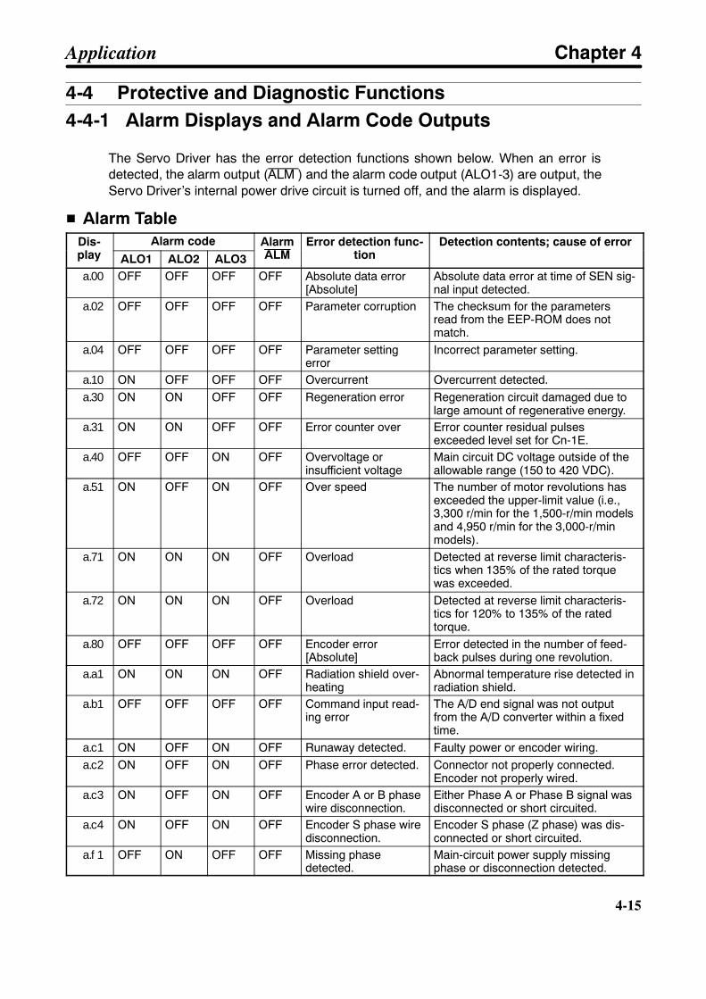
4-15
4-4 Protective and Diagnostic Functions4-4-1 Alarm Displays and Alarm Code Outputs
The Servo Driver has the error detection functions shown below. When an error isdetected, the alarm output (ALM ) and the alarm code output (ALO1-3) are output, theServo Driver’s internal power drive circuit is turned off, and the alarm is displayed.
H Alarm TableDis-play
Alarm code AlarmALM
Error detection func-tion
Detection contents; cause of errorDis-play ALO1 ALO2 ALO3
AlarmALM
Error detection func-tion
Detection contents; cause of error
a.00 OFF OFF OFF OFF Absolute data error[Absolute]
Absolute data error at time of SEN sig-nal input detected.
a.02 OFF OFF OFF OFF Parameter corruption The checksum for the parametersread from the EEP-ROM does notmatch.
a.04 OFF OFF OFF OFF Parameter settingerror
Incorrect parameter setting.
a.10 ON OFF OFF OFF Overcurrent Overcurrent detected.a.30 ON ON OFF OFF Regeneration error Regeneration circuit damaged due to
large amount of regenerative energy.a.31 ON ON OFF OFF Error counter over Error counter residual pulses
exceeded level set for Cn-1E.a.40 OFF OFF ON OFF Overvoltage or
insufficient voltageMain circuit DC voltage outside of theallowable range (150 to 420 VDC).
a.51 ON OFF ON OFF Over speed The number of motor revolutions hasexceeded the upper-limit value (i.e.,3,300 r/min for the 1,500-r/min modelsand 4,950 r/min for the 3,000-r/minmodels).
a.71 ON ON ON OFF Overload Detected at reverse limit characteris-tics when 135% of the rated torquewas exceeded.
a.72 ON ON ON OFF Overload Detected at reverse limit characteris-tics for 120% to 135% of the ratedtorque.
a.80 OFF OFF OFF OFF Encoder error[Absolute]
Error detected in the number of feed-back pulses during one revolution.
a.a1 ON ON ON OFF Radiation shield over-heating
Abnormal temperature rise detected inradiation shield.
a.b1 OFF OFF OFF OFF Command input read-ing error
The A/D end signal was not outputfrom the A/D converter within a fixedtime.
a.c1 ON OFF ON OFF Runaway detected. Faulty power or encoder wiring.a.c2 ON OFF ON OFF Phase error detected. Connector not properly connected.
Encoder not properly wired.a.c3 ON OFF ON OFF Encoder A or B phase
wire disconnection.Either Phase A or Phase B signal wasdisconnected or short circuited.
a.c4 ON OFF ON OFF Encoder S phase wiredisconnection.
Encoder S phase (Z phase) was dis-connected or short circuited.
a.f1 OFF ON OFF OFF Missing phasedetected.
Main-circuit power supply missingphase or disconnection detected.
Application Chapter 4
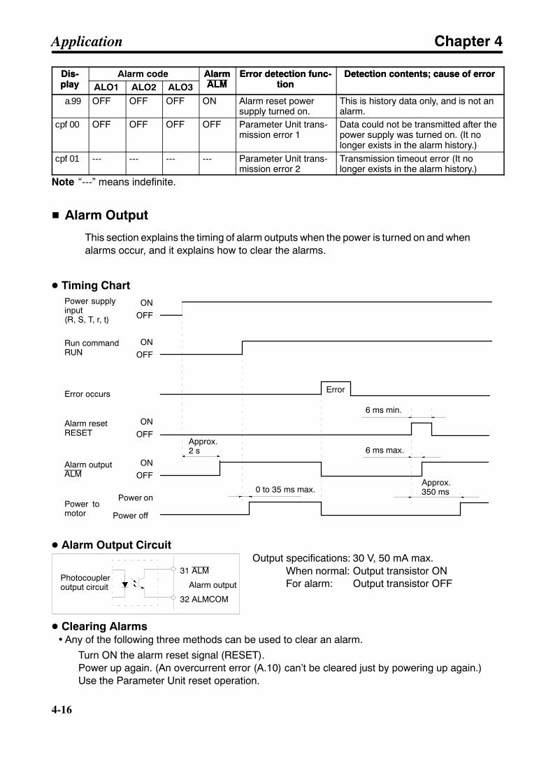
4-16
4-16
Dis-play
Detection contents; cause of errorError detection func-tion
AlarmALM
Alarm codeDis-play
Detection contents; cause of errorError detection func-tion
AlarmALMALO3ALO2ALO1
a.99 OFF OFF OFF ON Alarm reset powersupply turned on.
This is history data only, and is not analarm.
cpf00 OFF OFF OFF OFF Parameter Unit trans-mission error 1
Data could not be transmitted after thepower supply was turned on. (It nolonger exists in the alarm history.)
cpf01 --- --- --- --- Parameter Unit trans-mission error 2
Transmission timeout error (It nolonger exists in the alarm history.)
Note “---” means indefinite.
H Alarm Output
This section explains the timing of alarm outputs when the power is turned on and whenalarms occur, and it explains how to clear the alarms.
D Timing ChartON
OFF
ONOFF
ONOFF
ONOFF
0 to 35 ms max.
6 ms max.
6 ms min.
Power supplyinput(R, S, T, r, t)
Run commandRUN
Error occurs
Alarm resetRESET
Alarm outputALM
Power tomotor
Power on
Power off
Approx.2 s
Error
Approx.350 ms
D Alarm Output CircuitOutput specifications: 30 V, 50 mA max.
When normal: Output transistor ONFor alarm: Output transistor OFF
D Clearing Alarms• Any of the following three methods can be used to clear an alarm.
Turn ON the alarm reset signal (RESET).Power up again. (An overcurrent error (A.10) can’t be cleared just by powering up again.)Use the Parameter Unit reset operation.
31 ALM
32 ALMCOM
Photocoupleroutput circuit Alarm output
Application Chapter 4

!
4-17
Caution If an alarm is cleared while the run command (RUN) is ON, operation will beginimmediately after the alarm is cleared, which could be dangerous. Turn the run com-mand off before clearing alarms.When the run command is ON and bit 0 of setup parameter Cn-01 is set to “1” (Servoalways ON), be sure that it is safe to resume operation before clearing an alarm.
H Overload Characteristics (Electron Thermal Characteristics)
An overload protection function (electron thermal) is built into the Servo Driver to protectagainst Servo Driver or Servomotor overload. If an overload (A.71 to A.72) does occur,first clear the cause of the error and then wait at least one minute for the Servomotortemperature to drop before turning on the power again. If the power is turned on againtoo soon, the Servomotor coil may be damaged.
Overload characteristics are shown in the following table. If, for example, a current of three times theServomotor’s rated current flows continuously, it will be detected after approximately three seconds.
Load ratio (%)
Ope
ratio
ntim
e(s
)
Note The load ratio is calculated in relation to the Servomotor’s rated current.
Load ratio (%) =Servomotor current
Servomotor rated current× 100
Application Chapter 4
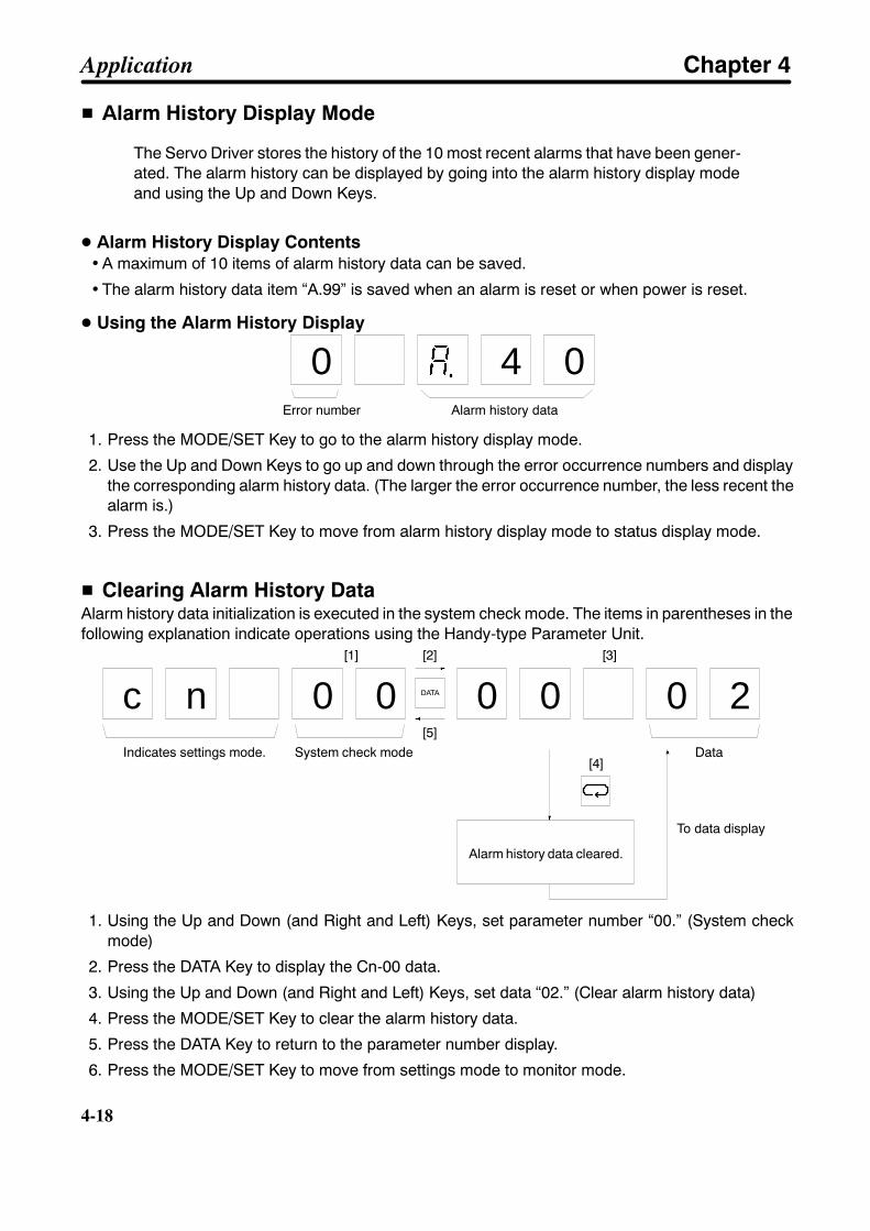
4-18
4-18
H Alarm History Display Mode
The Servo Driver stores the history of the 10 most recent alarms that have been gener-ated. The alarm history can be displayed by going into the alarm history display modeand using the Up and Down Keys.
D Alarm History Display Contents• A maximum of 10 items of alarm history data can be saved.
• The alarm history data item “A.99” is saved when an alarm is reset or when power is reset.
D Using the Alarm History Display
0 4 0Error number Alarm history data
1. Press the MODE/SET Key to go to the alarm history display mode.
2. Use the Up and Down Keys to go up and down through the error occurrence numbers and displaythe corresponding alarm history data. (The larger the error occurrence number, the less recent thealarm is.)
3. Press the MODE/SET Key to move from alarm history display mode to status display mode.
H Clearing Alarm History DataAlarm history data initialization is executed in the system check mode. The items in parentheses in thefollowing explanation indicate operations using the Handy-type Parameter Unit.
c n 0 0 0 0 0 2
[1] [2]
[5]Data
[3]
[4]
DATA
Indicates settings mode. System check mode
Alarm history data cleared.
To data display
1. Using the Up and Down (and Right and Left) Keys, set parameter number “00.” (System checkmode)
2. Press the DATA Key to display the Cn-00 data.
3. Using the Up and Down (and Right and Left) Keys, set data “02.” (Clear alarm history data)
4. Press the MODE/SET Key to clear the alarm history data.
5. Press the DATA Key to return to the parameter number display.
6. Press the MODE/SET Key to move from settings mode to monitor mode.
Application Chapter 4
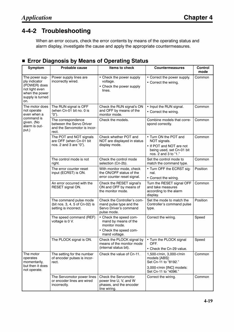
4-19
4-4-2 TroubleshootingWhen an error occurs, check the error contents by means of the operating status andalarm display, investigate the cause and apply the appropriate countermeasures.
H Error Diagnosis by Means of Operating StatusSymptom Probable cause Items to check Countermeasures Control
mode
The power sup-ply indicator(POWER) doesnot light evenwhen the powersupply is turnedon.
Power supply lines areincorrectly wired.
• Check the power supplyvoltage.
• Check the power supplylines.
• Correct the power supply.• Correct the wiring.
Common
The motor doesnot operateeven when acommand is
The RUN signal is OFF(when Cn-01 bit no. 0 is“0”).
Check the RUN signal’s ONand OFF by means of themonitor mode.
• Input the RUN signal.• Correct the wiring.
Common
even when acommand isgiven. (Noalarm is out-put.)
The correspondencebetween the Servo Driverand the Servomotor is incor-rect.
Check the models. Combine models that corre-spond correctly.
Common
The POT and NOT signalsare OFF (when Cn-01 bitnos. 2 and 3 are “0”).
Check whether POT andNOT are displayed in statusdisplay mode.
• Turn ON the POT andNOT signals.
• If POT and NOT are notbeing used, set Cn-01 bitnos. 2 and 3 to “1.”
Common
The control mode is notright.
Check the control modeselection (Cn-2b).
Set the control mode tomatch the command type.
Common
The error counter resetinput (ECRST) is ON.
With monitor mode, checkthe ON/OFF status of theerror counter reset signal.
• Turn OFF the ECRST sig-nal.
• Correct the wiring.
Position
An error occurred with theRESET signal ON.
Check the RESET signal’sON and OFF by means ofthe monitor mode.
Turn the RESET signal OFFand take measuresaccording to the alarmdisplay.
Common
The command pulse mode(bit nos. 3, 4, 5 of Cn-02) issetting is incorrect.
Check the Controller’s com-mand pulse type and theServo Driver’s commandpulse mode.
Set the mode to match theController’s command pulsetype.
Position
The speed command (REF)voltage is 0 V.
• Check the speed com-mand by means of themonitor mode.
• Check the speed com-mand voltage.
Correct the wiring. Speed
The PLOCK signal is ON. Check the PLOCK signal bymeans of the monitor mode(internal status bit).
• Turn the PLOCK signalOFF.
• Check the Cn-29 value.
Speed
The motoroperatesmomentarily,but then it doesnot operate.
The setting for the numberof encoder pulses is incor-rect.
Check the value of Cn-11. 1,500-r/min, 3,000-r/minmodels [ABS]:Set Cn-11 to “8192.”
3,000-r/min [INC] models:Set Cn-11 to “4096.”
Common
The Servomotor power linesor encoder lines are wiredincorrectly.
Check the Servomotorpower line U, V, and Wphases, and the encoderline wiring.
Correct the wiring. Common
Application Chapter 4
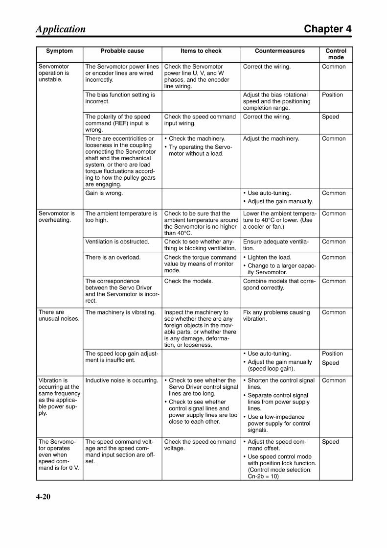
4-20
4-20
Symptom Controlmode
CountermeasuresItems to checkProbable cause
Servomotoroperation isunstable.
The Servomotor power linesor encoder lines are wiredincorrectly.
Check the Servomotorpower line U, V, and Wphases, and the encoderline wiring.
Correct the wiring. Common
The bias function setting isincorrect.
Adjust the bias rotationalspeed and the positioningcompletion range.
Position
The polarity of the speedcommand (REF) input iswrong.
Check the speed commandinput wiring.
Correct the wiring. Speed
There are eccentricities orlooseness in the couplingconnecting the Servomotorshaft and the mechanicalsystem, or there are loadtorque fluctuations accord-ing to how the pulley gearsare engaging.
• Check the machinery.• Try operating the Servo-
motor without a load.
Adjust the machinery. Common
Gain is wrong. • Use auto-tuning.• Adjust the gain manually.
Common
Servomotor isoverheating.
The ambient temperature istoo high.
Check to be sure that theambient temperature aroundthe Servomotor is no higherthan 40°C.
Lower the ambient tempera-ture to 40°C or lower. (Usea cooler or fan.)
Common
Ventilation is obstructed. Check to see whether any-thing is blocking ventilation.
Ensure adequate ventila-tion.
Common
There is an overload. Check the torque commandvalue by means of monitormode.
• Lighten the load.• Change to a larger capac-
ity Servomotor.
Common
The correspondencebetween the Servo Driverand the Servomotor is incor-rect.
Check the models. Combine models that corre-spond correctly.
Common
There areunusual noises.
The machinery is vibrating. Inspect the machinery tosee whether there are anyforeign objects in the mov-able parts, or whether thereis any damage, deforma-tion, or looseness.
Fix any problems causingvibration.
Common
The speed loop gain adjust-ment is insufficient.
• Use auto-tuning.• Adjust the gain manually
(speed loop gain).
Position
Speed
Vibration isoccurring at thesame frequencyas the applica-ble power sup-ply.
Inductive noise is occurring. • Check to see whether theServo Driver control signallines are too long.
• Check to see whethercontrol signal lines andpower supply lines are tooclose to each other.
• Shorten the control signallines.
• Separate control signallines from power supplylines.
• Use a low-impedancepower supply for controlsignals.
Common
The Servomo-tor operateseven whenspeed com-mand is for 0 V.
The speed command volt-age and the speed com-mand input section are off-set.
Check the speed commandvoltage.
• Adjust the speed com-mand offset.
• Use speed control modewith position lock function.(Control mode selection:Cn-2b = 10)
Speed
Application Chapter 4
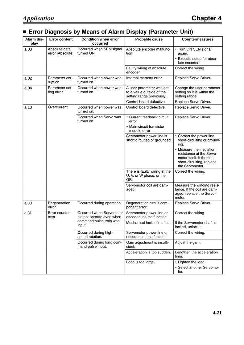
4-21
H Error Diagnosis by Means of Alarm Display (Parameter Unit)Alarm dis-
playError content Condition when error
occurredProbable cause Countermeasures
a.00 Absolute dataerror [Absolute]
Occurred when SEN signalturned ON.
Absolute encoder malfunc-tion
• Turn ON SEN signalagain.
• Execute setup for abso-lute encoder.
Faulty wiring of absoluteencoder
Correct the wiring.
a.02 Parameter cor-ruption
Occurred when power wasturned on.
Internal memory error Replace Servo Driver.
a.04 Parameter set-ting error
Occurred when power wasturned on.
A user parameter was setto a value outside of thesetting range previously.
Change the user parametersetting so it is within thesetting range.
Control board defective. Replace Servo Driver.
a.10 Overcurrent Occurred when power wasturned on.
Control board defective. Replace Servo Driver.
Occurred when Servo wasturned on.
• Current feedback circuiterror
• Main circuit transistormodule error
Replace Servo Driver.
Servomotor power line isshort-circuited or grounded.
• Correct the power lineshort-circuiting or ground-ing.
• Measure the insulationresistance at the Servo-motor itself. If there isshort-circuiting, replacethe Servomotor.
There is faulty wiring at theU, V, or W phase, or theGR.
Correct the wiring.
Servomotor coil are dam-aged.
Measure the winding resis-tance. If the coil are dam-aged, replace the Servo-motor.
a.30 Regenerationerror
Occurred during operation. Regeneration circuit com-ponent error
Replace Servo Driver.
a.31 Error counterover
Occurred when Servomotordid not operate even whencommand pulse train was
Servomotor power line orencoder line malfunction
Correct the wiring.over did not operate even when
command pulse train wasinput.
Mechanical lock is in effect. If the Servomotor shaft islocked, unlock it.
Occurred during high-speed rotation.
Servomotor power line orencoder line malfunction
Correct the wiring.
Occurred during long com-mand pulse input.
Gain adjustment is insuffi-cient.
Adjust the gain.mand pulse input.
Acceleration is too sudden. Lengthen the accelerationtime.
Load is too large. • Lighten the load.• Select another Servomo-
tor.
Application Chapter 4

4-22
4-22
Alarm dis-play
CountermeasuresProbable causeCondition when erroroccurred
Error content
a.40 Overvoltage;Insufficient volt-age
Occurred when power wasturned on.
The main-circuit powersupply voltage is outside ofthe allowable range.
• The main-circuit powersupply voltage must be170 to 253 VAC.age
Occurred during Servomo-tor deceleration.
The load inertia is toolarge.
• Lengthen the decelera-tion time.
• Select another Servomo-tor.
The main-circuit powersupply voltage hasexceeded the allowablerange.
Lower the voltage to withinthe allowable range.
Occurred while lowering(vertical shaft)
Gravity torque is too large. • Add a counterbalance tothe machine, and reducethe gravity torque.
• Reduce the loweringspeed.
a.51 Overspeeding High-speed rotationoccurred when commandwas input.
The rotation speedexceeded the upper-limitvalue (i.e., 3,300 r/min forthe 1,500-r/min models and4,950 for the 3,000-r/minmodels) due to overshoot-ing.
• Adjust the gain.• Lower the maximum
speed of the command.
Encoder is wired incor-rectly.
Correct the wiring.
a.71 Overload Occurred during operation. Operating at more than135% of the rated torque.(Effective torque)
• If the Servomotor shaft islocked, unlock it.
• If Servomotor power linesare incorrectly wired, cor-rect them.
• Lighten the load.• Lengthen the accelera-
tion time.• Adjust the gain.
Power supply voltage hasdropped.
Check the power supplyvoltage and raise it towithin the allowable range.
a.72 Overload Occurred during operation. Operating at 120% to 135%of the rated torque. (Effec-tive torque)
• Lighten the load.• Lengthen the accelera-
tion time.• Adjust the gain.
Power supply voltage hasdropped.
Check the power supplyvoltage and raise it towithin the allowable range.
a.80 Encoder error[Absolute]
Occurred during operation Absolute encoder faultywiring or poor contact.
Correct the wiring.[Absolute]
Pulse counter malfunction Turn OFF the SEN signaland input the alarm reset.Then turn ON the SEN sig-nal again.
Application Chapter 4
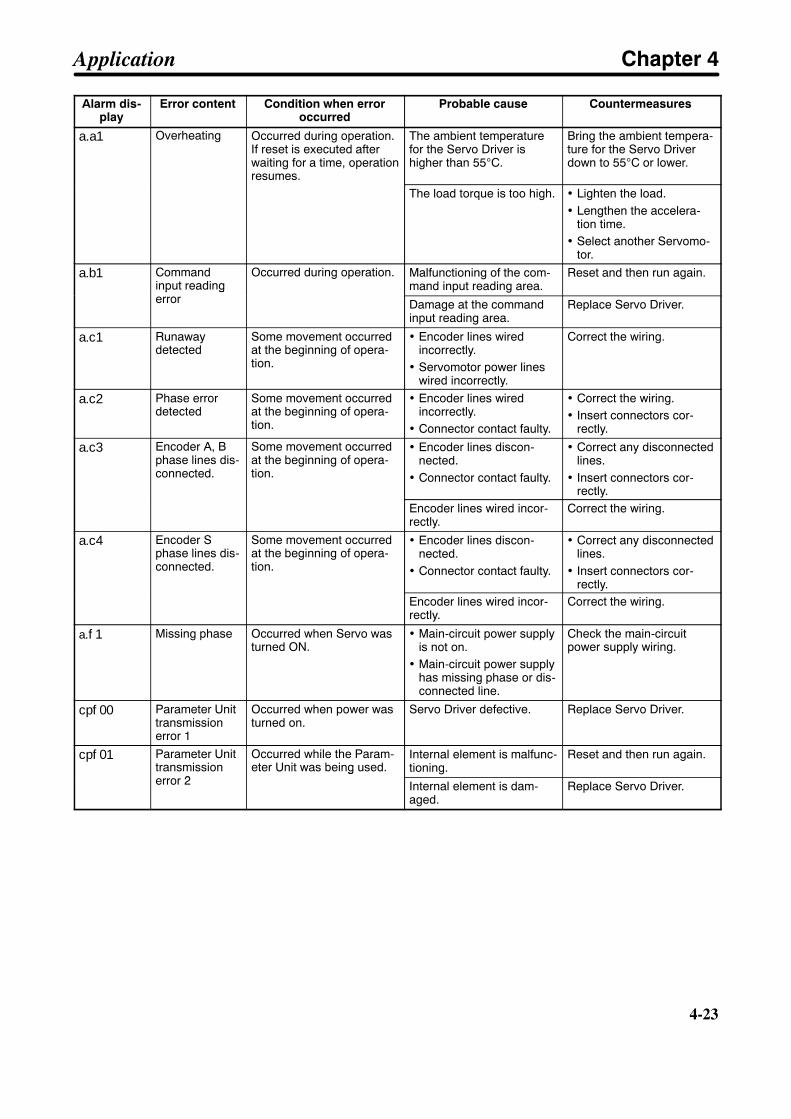
4-23
Alarm dis-play
CountermeasuresProbable causeCondition when erroroccurred
Error content
a.a1 Overheating Occurred during operation.If reset is executed afterwaiting for a time, operationresumes.
The ambient temperaturefor the Servo Driver ishigher than 55°C.
Bring the ambient tempera-ture for the Servo Driverdown to 55°C or lower.
The load torque is too high. • Lighten the load.• Lengthen the accelera-
tion time.• Select another Servomo-
tor.
a.b1 Commandinput readingerror
Occurred during operation. Malfunctioning of the com-mand input reading area.
Reset and then run again.input readingerror Damage at the command
input reading area.Replace Servo Driver.
a.c1 Runawaydetected
Some movement occurredat the beginning of opera-tion.
• Encoder lines wiredincorrectly.
• Servomotor power lineswired incorrectly.
Correct the wiring.
a.c2 Phase errordetected
Some movement occurredat the beginning of opera-tion.
• Encoder lines wiredincorrectly.
• Connector contact faulty.
• Correct the wiring.• Insert connectors cor-
rectly.
a.c3 Encoder A, Bphase lines dis-connected.
Some movement occurredat the beginning of opera-tion.
• Encoder lines discon-nected.
• Connector contact faulty.
• Correct any disconnectedlines.
• Insert connectors cor-rectly.
Encoder lines wired incor-rectly.
Correct the wiring.
a.c4 Encoder Sphase lines dis-connected.
Some movement occurredat the beginning of opera-tion.
• Encoder lines discon-nected.
• Connector contact faulty.
• Correct any disconnectedlines.
• Insert connectors cor-rectly.
Encoder lines wired incor-rectly.
Correct the wiring.
a.f1 Missing phase Occurred when Servo wasturned ON.
• Main-circuit power supplyis not on.
• Main-circuit power supplyhas missing phase or dis-connected line.
Check the main-circuitpower supply wiring.
cpf00 Parameter Unittransmissionerror 1
Occurred when power wasturned on.
Servo Driver defective. Replace Servo Driver.
cpf01 Parameter Unittransmissionerror 2
Occurred while the Param-eter Unit was being used.
Internal element is malfunc-tioning.
Reset and then run again.transmissionerror 2
eter Unit was being used.
Internal element is dam-aged.
Replace Servo Driver.
Application Chapter 4
!
!
4-24
4-24
4-5 Periodic Maintenance
WARNING Do not attempt to disassemble, repair, or modify any Units. Any attempt to do so mayresult in malfunction, fire, or electric shock.
Caution Resume operation only after transferring to the new Unit the contents of the datarequired for operation. Not doing so may result in an unexpected operation.
Servomotors and Servo Drivers contain many components and will operate properlyonly when each of the individual components is operating properly. Some of the electri-cal and mechanical components require maintenance depending on application condi-tions. In order to ensure proper long-term operation of Servomotors and Drivers, peri-odic inspection and part replacement is required according to the life of the components.
The periodic maintenance cycle depends on the installation environment and application conditions ofthe Servomotor or Driver. Recommended maintenance times are listed below for Servomotors andDrivers. Use these are reference in determining actual maintenance schedules.
H Servomotors• Recommended Periodic Maintenance
Bearings: 20,000 hours
Application Conditions: Ambient motor operating temperature of 40_C, within allowable shaft load,rated operation (rated torque and r/m), installed as described in operationmanual.
• The radial loads during operation (rotation) on timing pulleys and other components contacting belts istwice the still load. Consult with the belt and pulley manufacturers and adjust designs and system set-tings so that the allowable shaft load is not exceeded even during operation. If a motor is used under ashaft load exceeding the allowable limit, the motor shaft can break, the bearings can burn out, andother problems can occur.
H Servo Drivers• Recommended Periodic Maintenance
Aluminum analytical capacitors: 50,000 hours, at an ambient Servo Driver operating temperatureof 40_C, rated operation (rated torque) at 80% output, installedas described in operation manual.
Axle fan: 30,000 hours, at an ambient Servo Driver operating temperature of 40_C and an ambi-ent humidity of 65% RH.
• When using the Servo Driver under the continuous operation mode, cool the Servo Driver with fansand air conditioners to maintain an ambient operating temperature below 40_C.
• The life of aluminum analytical capacitors is greatly affected by the ambient operating temperature.Generally speaking, an increase of 10_C in the ambient operating temperature will reduce capacitorlife by 50%. We recommend that ambient operating temperature be lowered and the power supplytime be reduced as much as possible to lengthen the maintenance times for Servo Drivers.
Application Chapter 4
4-25
• If the Servomotor or Servo Driver is not to be used for a long time, or if they are to be used under condi-tions worse than those described above, a periodic inspection schedule of five years is recom-mended. Please consult with OMRON to determine whether or not components need to be replaced.
Application Chapter 4
Chapter 5
Specifications5-1 Servo Driver Specifications
5-2 Servomotor Specifications5-3 Cable Specifications
5-4 Parameter Unit Specifications
5
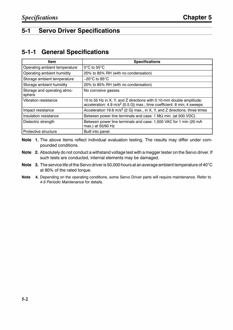
5-2
5-2
5-1 Servo Driver Specifications
5-1-1 General SpecificationsItem Specifications
Operating ambient temperature 0°C to 55°COperating ambient humidity 20% to 85% RH (with no condensation)Storage ambient temperature --20°C to 85°CStorage ambient humidity 20% to 85% RH (with no condensation)Storage and operating atmo-sphere
No corrosive gasses.
Vibration resistance 10 to 55 Hz in X, Y, and Z directions with 0.10-mm double amplitude;acceleration: 4.9 m/s2 0.5 G max.; time coefficient: 8 min; 4 sweeps
Impact resistance Acceleration 19.6 m/s2 2 G max., in X, Y, and Z directions, three timesInsulation resistance Between power line terminals and case: 1 MΩ min. (at 500 VDC)Dielectric strength Between power line terminals and case: 1,500 VAC for 1 min (20 mA
max.) at 50/60 HzProtective structure Built into panel.
Note 1. The above items reflect individual evaluation testing. The results may differ under com-pounded conditions.
Note 2. Absolutely do not conduct a withstand voltage test with a megger tester on the Servo driver. Ifsuch tests are conducted, internal elements may be damaged.
Note 3. The service life of the Servo driver is 50,000 hours at an average ambient temperature of 40°Cat 80% of the rated torque.
Note 4. Depending on the operating conditions, some Servo Driver parts will require maintenance. Refer to4-5 Periodic Maintenance for details.
Specifications Chapter 5
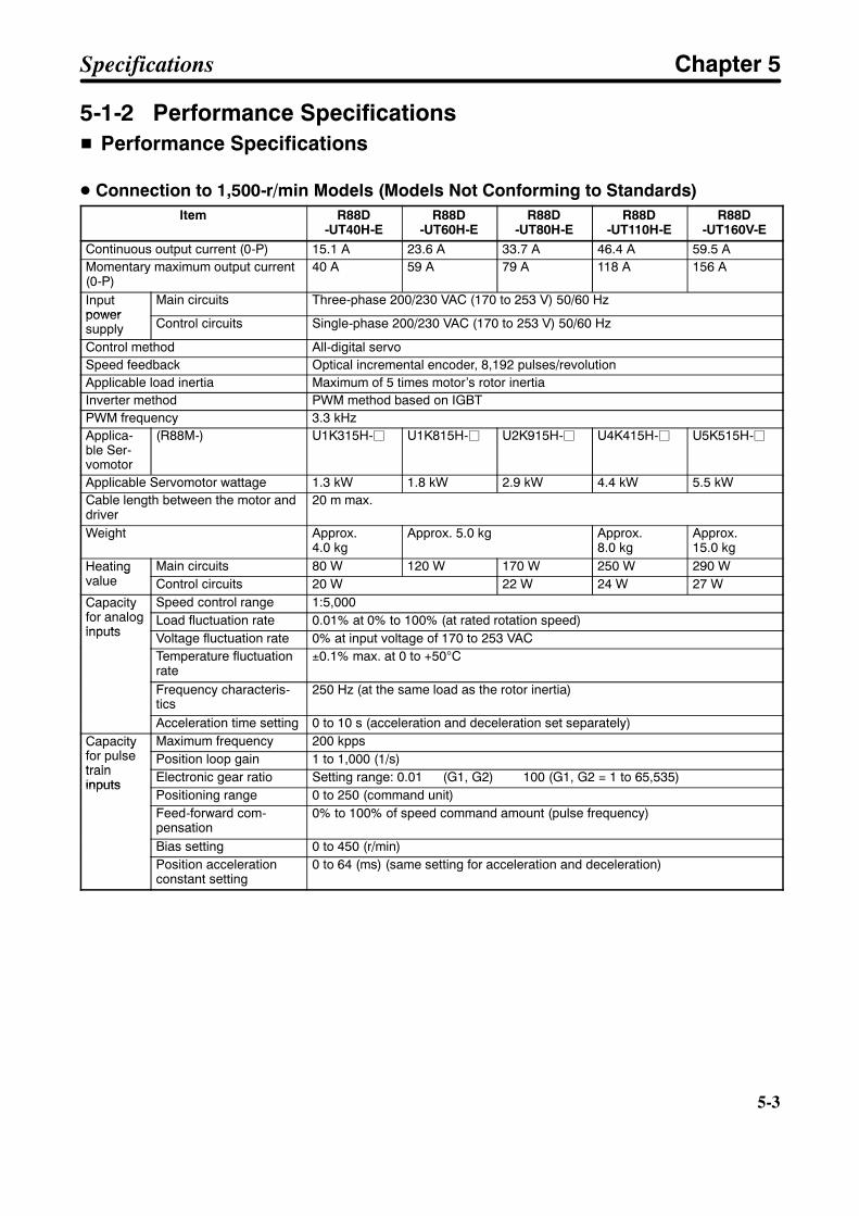
5-3
5-1-2 Performance SpecificationsH Performance Specifications
D Connection to 1,500-r/min Models (Models Not Conforming to Standards)Item R88D
-UT40H-ER88D
-UT60H-ER88D
-UT80H-ER88D
-UT110H-ER88D
-UT160V-EContinuous output current (0-P) 15.1 A 23.6 A 33.7 A 46.4 A 59.5 AMomentary maximum output current(0-P)
40 A 59 A 79 A 118 A 156 A
Inputpower
Main circuits Three-phase 200/230 VAC (170 to 253 V) 50/60 Hzpowersupply Control circuits Single-phase 200/230 VAC (170 to 253 V) 50/60 Hz
Control method All-digital servoSpeed feedback Optical incremental encoder, 8,192 pulses/revolutionApplicable load inertia Maximum of 5 times motor’s rotor inertiaInverter method PWM method based on IGBTPWM frequency 3.3 kHzApplica-ble Ser-vomotor
(R88M-) U1K315H-j U1K815H-j U2K915H-j U4K415H-j U5K515H-j
Applicable Servomotor wattage 1.3 kW 1.8 kW 2.9 kW 4.4 kW 5.5 kWCable length between the motor anddriver
20 m max.
Weight Approx.4.0 kg
Approx. 5.0 kg Approx.8.0 kg
Approx.15.0 kg
Heatingvalue
Main circuits 80 W 120 W 170 W 250 W 290 WHeatingvalue Control circuits 20 W 22 W 24 W 27 WCapacityfor analog
Speed control range 1:5,000Capacityfor analoginputs
Load fluctuation rate 0.01% at 0% to 100% (at rated rotation speed)inputs Voltage fluctuation rate 0% at input voltage of 170 to 253 VAC
Temperature fluctuationrate
±0.1% max. at 0 to +50°C
Frequency characteris-tics
250 Hz (at the same load as the rotor inertia)
Acceleration time setting 0 to 10 s (acceleration and deceleration set separately)Capacityfor pulse
Maximum frequency 200 kppsCapacityfor pulsetrain
Position loop gain 1 to 1,000 (1/s)traininputs Electronic gear ratio Setting range: 0.01 (G1, G2) 100 (G1, G2 = 1 to 65,535)inputs
Positioning range 0 to 250 (command unit)Feed-forward com-pensation
0% to 100% of speed command amount (pulse frequency)
Bias setting 0 to 450 (r/min)Position accelerationconstant setting
0 to 64 (ms) (same setting for acceleration and deceleration)
Specifications Chapter 5
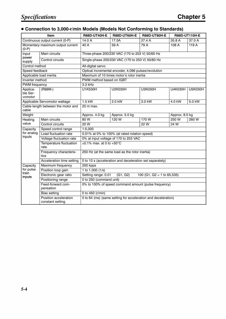
5-4
5-4
D Connection to 3,000-r/min Models (Models Not Conforming to Standards)Item R88D-UT40H-E R88D-UT60H-E R88D-UT80H-E R88D-UT110H-E
Continuous output current (0-P) 14.0 A 17.0A 27.4 A 35.8 A 37.0 AMomentary maximum output current(0-P)
40 A 59 A 79 A 108 A 119 A
Inputpower
Main circuits Three-phase 200/230 VAC (170 to 253 V) 50/60 Hzpowersupply Control circuits Single-phase 200/230 VAC (170 to 253 V) 50/60 Hz
Control method All-digital servoSpeed feedback Optical incremental encoder, 4,096 pulses/revolutionApplicable load inertia Maximum of 10 times motor’s rotor inertiaInverter method PWM method based on IGBTPWM frequency 3.3 kHzApplica-ble Ser-vomotor
(R88M-) U1K530H U2K030H U3K030H U4K030H U5K030H
Applicable Servomotor wattage 1.5 kW 2.0 kW 3.0 kW 4.0 kW 5.0 kWCable length between the motor andcable
20 m max.
Weight Approx. 4.0 kg Approx. 5.0 kg Approx. 8.0 kgHeatingvalue
Main circuits 80 W 120 W 170 W 250 W 260 WHeatingvalue Control circuits 20 W 22 W 24 WCapacityfor analog
Speed control range 1:5,000Capacityfor analoginputs
Load fluctuation rate 0.01% at 0% to 100% (at rated rotation speed)inputs Voltage fluctuation rate 0% at input voltage of 170 to 253 VAC
Temperature fluctuationrate
±0.1% max. at 0 to +50°C
Frequency characteris-tics
250 Hz (at the same load as the rotor inertia)
Acceleration time setting 0 to 10 s (acceleration and deceleration set separately)Capacityfor pulse
Maximum frequency 200 kppsCapacityfor pulsetrain
Position loop gain 1 to 1,000 (1/s)traininputs Electronic gear ratio Setting range: 0.01 (G1, G2) 100 (G1, G2 = 1 to 65,535)inputs
Positioning range 0 to 250 (command unit)Feed-forward com-pensation
0% to 100% of speed command amount (pulse frequency)
Bias setting 0 to 450 (r/min)Position accelerationconstant setting
0 to 64 (ms) (same setting for acceleration and deceleration)
Specifications Chapter 5
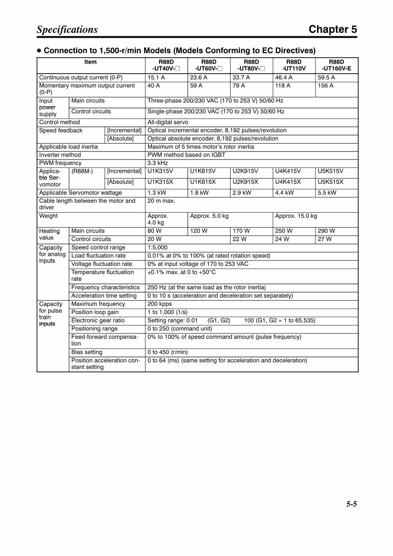
5-5
D Connection to 1,500-r/min Models (Models Conforming to EC Directives)Item R88D
-UT40V-jR88D
-UT60V-jR88D
-UT80V-jR88D
-UT110VR88D
-UT160V-EContinuous output current (0-P) 15.1 A 23.6 A 33.7 A 46.4 A 59.5 AMomentary maximum output current(0-P)
40 A 59 A 79 A 118 A 156 A
Inputpower
Main circuits Three-phase 200/230 VAC (170 to 253 V) 50/60 Hzpowersupply Control circuits Single-phase 200/230 VAC (170 to 253 V) 50/60 Hz
Control method All-digital servoSpeed feedback [Incremental] Optical incremental encoder, 8,192 pulses/revolutionSpeed feedback
[Absolute] Optical absolute encoder, 8,192 pulses/revolutionApplicable load inertia Maximum of 5 times motor’s rotor inertiaInverter method PWM method based on IGBTPWM frequency 3.3 kHzApplica-ble Ser-
(R88M-) [Incremental] U1K315V U1K815V U2K915V U4K415V U5K515Vble Ser-vomotor [Absolute] U1K315X U1K815X U2K915X U4K415X U5K515X
Applicable Servomotor wattage 1.3 kW 1.8 kW 2.9 kW 4.4 kW 5.5 kWCable length between the motor anddriver
20 m max.
Weight Approx.4.0 kg
Approx. 5.0 kg Approx. 15.0 kg
Heatingvalue
Main circuits 80 W 120 W 170 W 250 W 290 WHeatingvalue Control circuits 20 W 22 W 24 W 27 WCapacityfor analog
Speed control range 1:5,000Capacityfor analoginputs
Load fluctuation rate 0.01% at 0% to 100% (at rated rotation speed)inputs Voltage fluctuation rate 0% at input voltage of 170 to 253 VAC
Temperature fluctuationrate
±0.1% max. at 0 to +50°C
Frequency characteristics 250 Hz (at the same load as the rotor inertia)Acceleration time setting 0 to 10 s (acceleration and deceleration set separately)
Capacityfor pulse
Maximum frequency 200 kppsCapacityfor pulsetrain
Position loop gain 1 to 1,000 (1/s)traininputs Electronic gear ratio Setting range: 0.01 (G1, G2) 100 (G1, G2 = 1 to 65,535)inputs
Positioning range 0 to 250 (command unit)Feed-forward compensa-tion
0% to 100% of speed command amount (pulse frequency)
Bias setting 0 to 450 (r/min)Position acceleration con-stant setting
0 to 64 (ms) (same setting for acceleration and deceleration)
Specifications Chapter 5

5-6
5-6
D Connection to 3,000-r/min Models (Models Conforming to EC Directives)Item R88D-
UT24V-jR88D
-UT40V-jR88D
-UT60V-jR88D
-UT80V-jR88D-UT110V
Continuous output current (0-P) 8.6 A 14.0 A 17.0A 27.4 A 37.0 AMomentary maximum output current(0-P)
24 A 40 A 59 A 79 A 108 A 119 A
Inputpower
Main circuits Three-phase 200/230 VAC (170 to 253 V) 50/60 Hzpowersupply Control circuits Single-phase 200/230 VAC (170 to 253 V) 50/60 Hz
Control method All-digital servoSpeedfeedback
[Incremental] Optical incremental encoder, 4,096 pulses/revolutionSpeedfeedback [Absolute] Optical absolute encoder, 8,192 pulses/revolutionApplicable load inertia Maximum of 10 times motor’s rotor inertiaInverter method PWM method based on IGBTPWM frequency 3.3 kHzApplica-ble Ser-
(R88M-) [Incremental] U1K030V U1K530V U2K030V U3K030V U4K030V U5K030Vble Ser-vomotor [Absolute] U1K030X U1K530X U2K030X U3K030X U4K030X U5K030X
Applicable Servomotor wattage 1.0 kW 1.5 kW 2.0 kW 3.0 kW 4.0 kW 5.0 kWWeight Approx. 4.0 kg Approx. 5.0 kg Approx. 15.0 kgHeatingvalue
Main circuits 55 W 80 W 120 W 170 W 250 W 260 WHeatingvalue Control circuits 20 W 22 W 24 WCapacityfor analog
Speed control range 1:5,000Capacityfor analoginputs
Load fluctuation rate 0.01% at 0% to 100% (at rated rotation speed)inputs Voltage fluctuation rate 0% at input voltage of 170 to 253 VAC
Temperature fluctuationrate
±0.1% max. at 0 to +50°C
Frequency characteris-tics
250 Hz (at the same load as the rotor inertia)
Acceleration time setting 0 to 10 s (acceleration and deceleration set separately)Capacityfor pulse
Maximum frequency 200 kppsCapacityfor pulsetrain
Position loop gain 1 to 1,000 (1/s)traininputs Electronic gear ratio Setting range: 0.01 (G1, G2) 100 (G1, G2 = 1 to 65,535)inputs
Positioning range 0 to 250 (command unit)Feed-forward com-pensation
0% to 100% of speed command amount (pulse frequency)
Bias setting 0 to 450 (r/min)Position accelerationconstant setting
0 to 64 (ms) (same setting for acceleration and deceleration)
Specifications Chapter 5
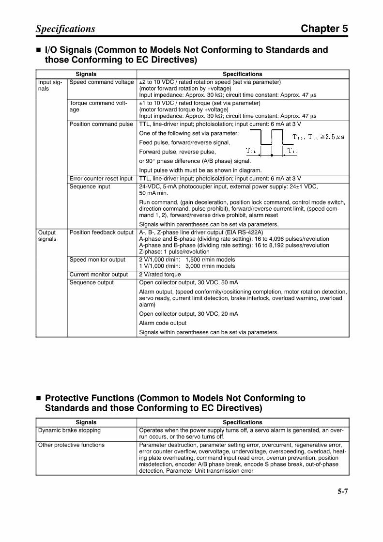
5-7
H I/O Signals (Common to Models Not Conforming to Standards andthose Conforming to EC Directives)
Signals SpecificationsInput sig-nals
Speed command voltage ±2 to 10 VDC / rated rotation speed (set via parameter)(motor forward rotation by +voltage)Input impedance: Approx. 30 kΩ; circuit time constant: Approx. 47 µs
Torque command volt-age
±1 to 10 VDC / rated torque (set via parameter)(motor forward torque by +voltage)Input impedance: Approx. 30 kΩ; circuit time constant: Approx. 47 µs
Position command pulse TTL, line-driver input; photoisolation; input current: 6 mA at 3 V
One of the following set via parameter:
Feed pulse, forward/reverse signal,
Forward pulse, reverse pulse,
or 90_ phase difference (A/B phase) signal.
Input pulse width must be as shown in diagram.Error counter reset input TTL, line-driver input; photoisolation; input current: 6 mA at 3 VSequence input 24-VDC, 5-mA photocoupler input, external power supply: 24±1 VDC,
50 mA min.
Run command, (gain deceleration, position lock command, control mode switch,direction command, pulse prohibit), forward/reverse current limit, (speed com-mand 1, 2), forward/reverse drive prohibit, alarm reset
Signals within parentheses can be set via parameters.Outputsignals
Position feedback output A-, B-, Z-phase line driver output (EIA RS-422A)A-phase and B-phase (dividing rate setting): 16 to 4,096 pulses/revolutionA-phase and B-phase (dividing rate setting): 16 to 8,192 pulses/revolutionZ-phase: 1 pulse/revolution
Speed monitor output 2 V/1,000 r/min: 1,500 r/min models1 V/1,000 r/min: 3,000 r/min models
Current monitor output 2 V/rated torqueSequence output Open collector output, 30 VDC, 50 mA
Alarm output, (speed conformity/positioning completion, motor rotation detection,servo ready, current limit detection, brake interlock, overload warning, overloadalarm)
Open collector output, 30 VDC, 20 mA
Alarm code output
Signals within parentheses can be set via parameters.
H Protective Functions (Common to Models Not Conforming toStandards and those Conforming to EC Directives)
Signals SpecificationsDynamic brake stopping Operates when the power supply turns off, a servo alarm is generated, an over-
run occurs, or the servo turns off.Other protective functions Parameter destruction, parameter setting error, overcurrent, regenerative error,
error counter overflow, overvoltage, undervoltage, overspeeding, overload, heat-ing plate overheating, command input read error, overrun prevention, positionmisdetection, encoder A/B phase break, encode S phase break, out-of-phasedetection, Parameter Unit transmission error
Specifications Chapter 5

5-8
5-8
5-1-3 I/O Specifications
H Terminal Block Specifications (Models Not Conforming to Standards)Signal Function Condition
Frame ground This is the ground terminal. Ground to a maximum of 100 Ω (class-3).
RST
Main circuitspower supplyinput
Three-phase 200/230 VAC (170 to 253 VAC) 50/60 Hz
rt
Control circuitspower supplyinput
Single-phase 200/230 VAC (170 to 253 VAC) 50/60 Hz
P1B
Regenerativeresistor connec-tion terminals
Regenerative resistor connection terminal for a Servo Driver of 5.5 kW min.(R88D-UT160H-E only)
PN
Main circuit DCoutput
Do not connect anything to these terminals
U ServomotorU-phase output
Red These are the terminals for outputs to the Servomotor. Be sure towire these terminals correctly.
V ServomotorV-phase output
Whitewire these terminals correctly.
W ServomotorW-phase output
Black
Frame ground Green
Note Servo Drivers of 5.0 kW or less are not provided with the P1 terminal.
H Terminal Block Specifications (Models Conforming to EC Directives)Signal Function Condition
Frame ground This is the ground terminal. Ground to a maximum of 100 Ω (class-3).
L1L2L3
Main circuitspower supplyinput
Three-phase 200/230 VAC (170 to 253 VAC) 50/60 Hz
L1CL3C
Control circuitspower supplyinput
Single-phase 200/230 VAC (170 to 253 VAC) 50/60 Hz
+ (+1)B
Main circuit DCoutput(Forward)
Be sure to connect a regenerative resistor (corresponding to the amount ofregenerative energy) between the + and B terminals for the R88D-UTjV-RGand between the +1 and B terminals for the R88D-UT110V. Refer to 3-6-3Absorption of Regenerative Energy with External Regenerative Resistors-- Main circuit DC
output (Reverse)
and between the +1 and B terminals for the R88D-UT110V. Refer to 3-6-3Absorption of Regenerative Energy with External Regenerative ResistorsConnected to Models Complying with EC Directives for details.
U ServomotorU-phase output
Red These are the terminals for outputs to the Servomotor. Be sure towire these terminals correctly.
V ServomotorV-phase output
Whitewire these terminals correctly.
W ServomotorW-phase output
Black
Frame ground Green
Specifications Chapter 5
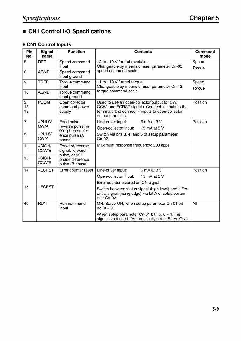
5-9
H CN1 Control I/O Specifications
D CN1 Control InputsPinNo.
Signalname
Function Contents Commandmode
5 REF Speed commandinput
±2 to ±10 V / rated revolutionChangeable by means of user parameter Cn-03speed command scale.
Speed
Torque6 AGND Speed command
input ground
Changeable by means of user parameter Cn-03speed command scale.
Torque
9 TREF Torque commandinput
±1 to ±10 V / rated torqueChangeable by means of user parameter Cn-13torque command scale.
Speed
Torque10 AGND Torque command
input ground
Changeable by means of user parameter Cn-13torque command scale.
Torque
31318
PCOM Open collectorcommand powersupply
Used to use an open-collector output for CW,CCW, and ECRST signals. Connect + inputs to theterminals and connect -- inputs to open-collectoroutput terminals.
Position
7 +PULS/CW/A
Feed pulse,reverse pulse, or90_ phase differ-
Line-driver input: 6 mA at 3 V
Open-collector input: 15 mA at 5 V
Position
8 --PULS/CW/A
90_ phase differ-ence pulse (Aphase)
Open-collector input: 15 mA at 5 V
Switch via bits 3, 4, and 5 of setup parameterCn-02.
Maximum response frequency: 200 kpps11 +SIGN/CCW/B
Forward/reversesignal, forwardpulse, or 90_
Maximum response frequency: 200 kpps
12 --SIGN/CCW/B
pulse, or 90_phase differencepulse (B phase)
14 --ECRST Error counter reset Line-driver input: 6 mA at 3 V
Open-collector input: 15 mA at 5 V
Error counter cleared on ON signal
Position
15 +ECRSTError counter cleared on ON signal
Switch between status signal (high level) and differ-ential signal (rising edge) via bit A of setup param-eter Cn-02.
40 RUN Run commandinput
ON: Servo ON, when setup parameter Cn-01 bitno. 0 = 0.
Allinput no. 0 = 0.
When setup parameter Cn-01 bit no. 0 = 1, thissignal is not used. (Automatically set to Servo ON.)
Specifications Chapter 5

5-10
5-10
PinNo.
Commandmode
ContentsFunctionSignalname
41 MING Gain decelerationinput
When user parameter CN-2b = 0 or 1, and SPD1and SPD2 are both OFF and parameter Cn-2b = 3,4, or 5, then
ON: Decrease speed loop gain
Position
Speed
TVSEL Control modeswitch input
When user parameter Cn-2b = 7, 8, or 9, then
ON: Change control mode
Switch controlmode
PLOCK Position lock com-mand input
When user parameter Cn-2b = 10, then
ON: position lock goes in effect if the motor rotationspeed is no more than the position lock rotationspeed (Cn-29).
Position lockspeed
IPG Pulse disable input When user parameter Cn-2b = 11, then
ON: Command pulse inputs are ignored and themotor stops.
Position(pulse dis-abled)
RDIR Rotation directioncommand inputs
When user parameter Cn-2b = 3, 4, 5, or 6 and aninternal set speed is selected, this is the rotationdirection command for internal speed settings 1 to3. (OFF: Forward rotation, ON: Reverse rotation)
Internal set-ting
Speed control
42 POT Forward drive pro-hibit input
Forward rotation overtravel input (OFF when pro-hibited). When setup parameter Cn-01 bit no. 2 =1, this signal is not used.
All
43 NOT Reverse drive pro-hibit input
Reverse rotation overtravel input (OFF when pro-hibited). When setup parameter Cn-01 bit no. 3 =1, this signal is not used.
All
44 RESET Alarm reset input ON: Servo alarm status is reset. All45 PCL/
SPD1Forward rotationcurrent limit input /Speed selectioncommand 1 input
Forward/reverse rotation current limit (PCL/NCL)when user parameter Cn-2b = 0, 1, 2, 7, 8, 9, 10,or 11 (ON: Current limit)Internal setting speed (Cn-1F, 20, 21) selectorswitch when user parameter Cn-2b = 3, 4, 5, or 6
All
46 NCL/SPD2
Reverse rotationcurrent limit input /Speed selectioncommand 2 input
Internal setting speed (Cn-1F, 20, 21) selectorswitch when user parameter Cn-2b = 3, 4, 5, or 6
47 +24VIN +24-V power sup-ply input for controlDC
Power supply for pin nos. 40, 41, 42, 43, 44, 45,and 46; +24-V input
All
4 SEN Sensor ON input ON: 5-V power supplies to absolute encoder [abso-lute]
Speed
2 SENGND Sensor ON inputground
lute]
The signal is not used when setup parameterCn-01 bit no. 1 = 1.
21 BAT Backup battery +input
Backup battery connector terminals for power inter-ruption for absolute encoder [absolute]
Speed
22 BATGND Backup battery --input
ruption for absolute encoder [absolute]
Specifications Chapter 5

5-11
D CN1 Control Outputs
PinNo.
Signalname
Function Contents Commandmode
1 GND Ground common Ground for the encoder output, alarm code, andmonitor output
All
16 AM Current monitor Voltage is output centered on 0 V according to thefollowing ratio: 2 V/(rated torque)
Forward acceleration is negative, reverse accelera-tion is positive.
Output accuracy is approximately ¦10%
All
17 NM Speed monitor Voltage is output centered on 0 V according to thefollowing ratio: 1 V/(1,000 r/min)
Forward is negative, reverse is positive.
Output accuracy is approximately ¦10%
All
19 +Z Encoder Z-phase+ output
Encoder Z-phase output (1 pulse/revolution). Linedriver output (conforming to RS-422A).
All
20 --Z Encoder Z-phase-- output
driver output (conforming to RS-422A).
23 P12 Built-in commandpower supply
Power supply for speed commands and torque com-mands.
Speed
Torque24 N12
power supply mands.
Can be used for speed and torque commands byconnecting an external variable resistor.
Torque
The function of the following pairs of signals is set in user parameter CN-2d (output signal selection);25 (+) and 26 (--), 27 (+) and 28 (--), 29 (+) and 30 (--)
25to30
VCMP Speed conformityoutput
Output (ON) when the Servomotor speed error iswithin the speed conformity signal output range(Cn-22).
Speed
30INP Positioning com-
pletion outputOutput (ON) when the position error is within thepositioning completion range (Cn-1b).
Position
TGON Servomotor rota-tion detection out-put
Output (ON) if the Servomotor rotation speedexceeds the value set for the Servomotor rotationdetection speed (Cn-0b).
All
READY Servo ready output Output (ON) if no errors are discovered after power-ing the main circuits.
All
CLIMT Current limit detec-tion output
The CLIMT signal will turned ON in any of the fol-lowing 3 cases:
• The output torque reaches the value set for thetorque limit (Cn-08, -09)
• The forward/reverse rotation current limit (PCL/NCL) is ON and the output torque reaches the exter-nal current limit set in Cn-18 or Cn-19.
All
• The output torque reaches the analog current limitinput (TREF). (When Cn-02 bit no. 8 = 1)
Speed
BKIR Brake interlockoutput
Outputs external brake interlock signal according tosetting in Cn-12, 15, and 16.
All
OLWRN Overload warningoutput
Goes OFF when the effective torque exceeds 20%of the overload detection level.
All
OLALM Overload alarmoutput
Goes OFF when an overload is detected.
Goes ON when the alarm reset is input.
All
Specifications Chapter 5
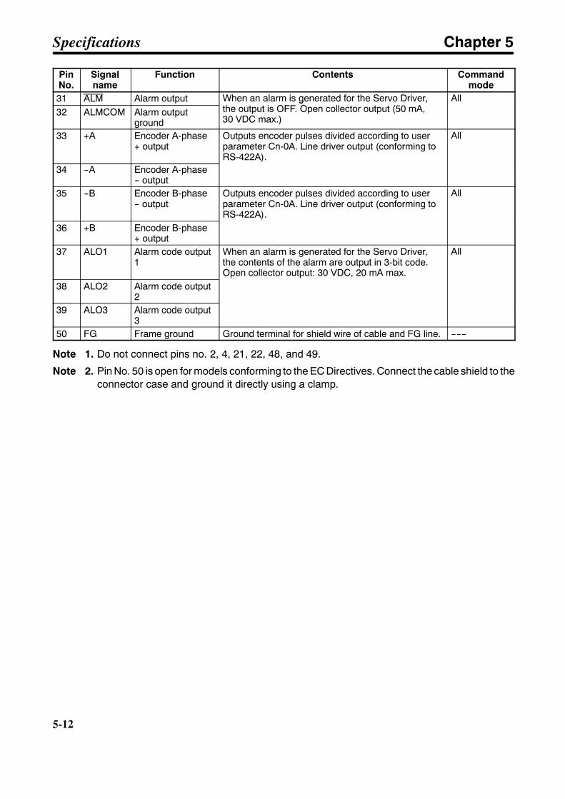
5-12
5-12
PinNo.
Commandmode
ContentsFunctionSignalname
31 ALM Alarm output When an alarm is generated for the Servo Driver,the output is OFF. Open collector output (50 mA,
All32 ALMCOM Alarm output
ground
When an alarm is generated for the Servo Driver,the output is OFF. Open collector output (50 mA,30 VDC max.)
All
33 +A Encoder A-phase+ output
Outputs encoder pulses divided according to userparameter Cn-0A. Line driver output (conforming toRS-422A).
All
34 --A Encoder A-phase-- output
35 --B Encoder B-phase-- output
Outputs encoder pulses divided according to userparameter Cn-0A. Line driver output (conforming toRS-422A).
All
36 +B Encoder B-phase+ output
37 ALO1 Alarm code output1
When an alarm is generated for the Servo Driver,the contents of the alarm are output in 3-bit code.Open collector output: 30 VDC, 20 mA max.
All
38 ALO2 Alarm code output2
39 ALO3 Alarm code output3
50 FG Frame ground Ground terminal for shield wire of cable and FG line. ------
Note 1. Do not connect pins no. 2, 4, 21, 22, 48, and 49.
Note 2. Pin No. 50 is open for models conforming to the EC Directives. Connect the cable shield to theconnector case and ground it directly using a clamp.
Specifications Chapter 5
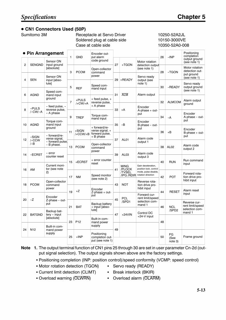
5-13
D CN1 Connectors Used (50P)Sumitomo 3M Receptacle at Servo Driver 10250-52A2JL
Soldered plug at cable side 10150-3000VECase at cable side 10350-52A0-008
2
4
6
8 --PULS/--CW/--A
10 AGND
12--SIGN/--CCW/--B
14 --ECRST
16 AM
18 PCOM
1 GND
3 PCOM
5
7+PULS/+CW/+A
9 TREF
11 +SIGN/+CCW/+B
13 PCOM
15 +ECRST
17 NM
27 +TGON
29 +READY
33
35
37 AL01
39 AL03
41MING/PLOCK/TVSEL/IPG /RDIR
43 NOT
31 ALM
26 --INP
28 --TGON
32 ALMCOM
34
36
38 AL02
40 RUN
42 POT
30 --READY
-- feed pulse, --reverse pulse,-- A phase
Torque com-mand inputground
-- forward/re-verse signal,-- forward pulse,-- B phase.
-- errorcounter reset
Current moni-tor (see note2)
Open-collectorcommandpower
Encoder out-put alarmcode ground
Open-collectorcommandpower
+ feed pulse, +reverse pulse,+ A phase
Torque com-mand input
+ forward/re-verse signal, +forward pulse,+ B phase
Open-collectorcommandpower
Motor rotationdetection output(see note 1)
Servo readyoutput (seenote 1)
Alarm output
Alarm codeoutput 1
Alarm codeoutput 3
Gain deceleration,position lock, controlmode, pulse disable,rotation direction
Positioningcompletionoutput ground(see note 1)
Motor rotationdetection out-put ground(see note 1)
Servo readyoutput ground(see note 1)
Alarm outputground
Alarm codeoutput 2
Run commandinput
Forward rota-tion drive pro-hibit input
AGNDSpeed com-mand inputground
20 --ZEncoderZ-phase -- out-put
22
24 N12Built-in com-mand powersupply
REF
19 +Z
21
23 P12
25 +INP
EncoderZ-phase + out-put
+ error counterreset
Speed monitor(see note 2)
Built-in com-mand powersupply
Positioningcompletion out-put (see note 1)
Speed com-mand input
45 PCL/SPD1
47 +24VIN
49
Forward cur-rent limit/speedselection com-mand 1
Control DC+24-V input
EncoderA-phase + out-put
EncoderB-phase -- out-put
+A
--B
44
46 NCL/SPD2
48
50FG(Seenote 3)
Reverse cur-rent limit/speedselection com-mand 1
Frame ground
--A
+B
RESET Alarm resetinput
EncoderB-phase + out-put
EncoderA-phase -- out-put
D Pin Arrangement
Reverse rota-tion drive pro-hibit input
SENGNDSensor ONinput ground[absolute]
SENSensor ONinput [abso-lute]
BATGNDBackup bat-tery -- input[absolute]
BATBackup battery+ input [abso-lute]
Note 1. The output terminal function of CN1 pins 25 through 30 are set in user parameter Cn-2d (out-put signal selection). The output signals shown above are the factory settings.
S Positioning completion (INP: position control)/speed conformity (VCMP: speed control)SMotor rotation detection (TGON) S Servo ready (READY)S Current limit detection (CLIMT) S Break interlock (BKIR)S Overload warning (OLWRN) S Overload alarm (OLARM)
Specifications Chapter 5
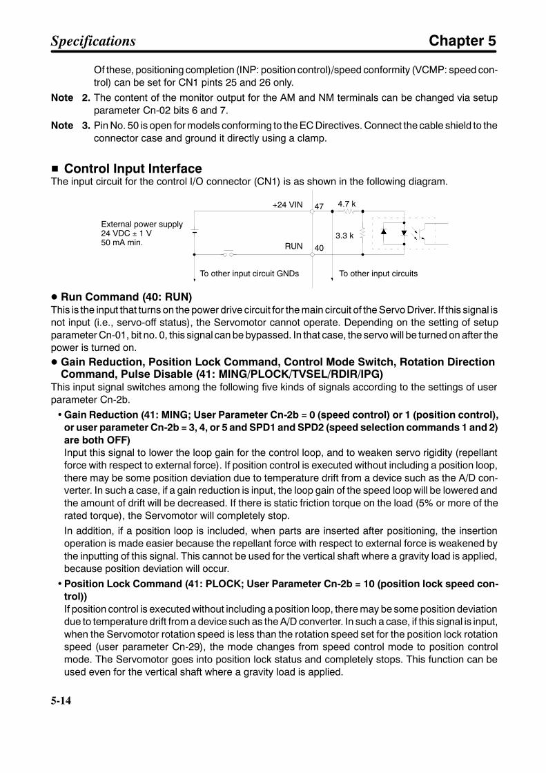
5-14
5-14
Of these, positioning completion (INP: position control)/speed conformity (VCMP: speed con-trol) can be set for CN1 pints 25 and 26 only.
Note 2. The content of the monitor output for the AM and NM terminals can be changed via setupparameter Cn-02 bits 6 and 7.
Note 3. Pin No. 50 is open for models conforming to the EC Directives. Connect the cable shield to theconnector case and ground it directly using a clamp.
H Control Input InterfaceThe input circuit for the control I/O connector (CN1) is as shown in the following diagram.
+24 VIN
RUN
47
40
4.7 k
3.3 kExternal power supply24 VDC ± 1 V50 mA min.
To other input circuit GNDs To other input circuits
D Run Command (40: RUN)This is the input that turns on the power drive circuit for the main circuit of the Servo Driver. If this signal isnot input (i.e., servo-off status), the Servomotor cannot operate. Depending on the setting of setupparameter Cn-01, bit no. 0, this signal can be bypassed. In that case, the servo will be turned on after thepower is turned on.D Gain Reduction, Position Lock Command, Control Mode Switch, Rotation Direction
Command, Pulse Disable (41: MING/PLOCK/TVSEL/RDIR/IPG)This input signal switches among the following five kinds of signals according to the settings of userparameter Cn-2b.
• Gain Reduction (41: MING; User Parameter Cn-2b = 0 (speed control) or 1 (position control),or user parameter Cn-2b = 3, 4, or 5 and SPD1 and SPD2 (speed selection commands 1 and 2)are both OFF)Input this signal to lower the loop gain for the control loop, and to weaken servo rigidity (repellantforce with respect to external force). If position control is executed without including a position loop,there may be some position deviation due to temperature drift from a device such as the A/D con-verter. In such a case, if a gain reduction is input, the loop gain of the speed loop will be lowered andthe amount of drift will be decreased. If there is static friction torque on the load (5% or more of therated torque), the Servomotor will completely stop.In addition, if a position loop is included, when parts are inserted after positioning, the insertionoperation is made easier because the repellant force with respect to external force is weakened bythe inputting of this signal. This cannot be used for the vertical shaft where a gravity load is applied,because position deviation will occur.
• Position Lock Command (41: PLOCK; User Parameter Cn-2b = 10 (position lock speed con-trol))If position control is executed without including a position loop, there may be some position deviationdue to temperature drift from a device such as the A/D converter. In such a case, if this signal is input,when the Servomotor rotation speed is less than the rotation speed set for the position lock rotationspeed (user parameter Cn-29), the mode changes from speed control mode to position controlmode. The Servomotor goes into position lock status and completely stops. This function can beused even for the vertical shaft where a gravity load is applied.
Specifications Chapter 5
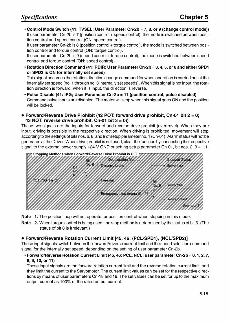
5-15
• Control Mode Switch (41: TVSEL; User Parameter Cn-2b = 7, 8, or 9 (change control mode))If user parameter Cn-2b is 7 (position control + speed control), the mode is switched between posi-tion control and speed control (ON: speed control).If user parameter Cn-2b is 8 (position control + torque control), the mode is switched between posi-tion control and torque control (ON: torque control).If user parameter Cn-2b is 9 (speed control + torque control), the mode is switched between speedcontrol and torque control (ON: speed control).
• Rotation Direction Command (41: RDIR; User Parameter Cn-2b = 3, 4, 5, or 6 and either SPD1or SPD2 is ON for internally set speed)This signal becomes the rotation direction change command for when operation is carried out at theinternally set speed (no. 1 through no. 3 internally set speeds). When this signal is not input, the rota-tion direction is forward; when it is input, the direction is reverse.
• Pulse Disable (41: IPG; User Parameter Cn-2b = 11 (position control, pulse disabled)Command pulse inputs are disabled. The motor will stop when this signal goes ON and the positionwill be locked.
D Forward/Reverse Drive Prohibit (42 POT: forward drive prohibit, Cn-01 bit 2 = 0;43 NOT: reverse drive prohibit, Cn-01 bit 3 = 0))
These two signals are the inputs for forward and reverse drive prohibit (overtravel). When they areinput, driving is possible in the respective direction. When driving is prohibited, movement will stopaccording to the settings of bits nos. 6, 8, and 9 of setup parameter no. 1 (Cn-01). Alarm status will not begenerated at the Driver. When drive prohibit is not used, clear the function by connecting the respectivesignal to the external power supply +24-V GND or setting setup parameter Cn-01, bit nos. 2, 3 = 1,1.
Stopping Methods when Forward/Reverse Drive Prohibit is OFF
BitNo. 80
BitNo. 60
1
1POT (NOT) is OFF
Deceleration Method
Dynamic brake
Free run
Emergency stop torque (Cn-06)
Servo free
Stopped Status
Servo free
Servo locked
BitNo. 90
1
See note 1.
Note 1. The position loop will not operate for position control when stopping in this mode.Note 2. When torque control is being used, the stop method is determined by the status of bit 6. (The
status of bit 8 is irrelevant.)
D Forward/Reverse Rotation Current Limit [45, 46: (PCL/SPD1), (NCL/SPD2)]These input signals switch between the forward/reverse current limit and the speed selection commandsignal for the internally set speed, depending on the setting of user parameter Cn-2b.
• Forward/Reverse Rotation Current Limit (45, 46: PCL, NCL; user parameter Cn-2b = 0, 1, 2, 7,8, 9, 10, or 11)These input signals are the forward rotation current limit and the reverse rotation current limit, andthey limit the current to the Servomotor. The current limit values can be set for the respective direc-tions by means of user parameters Cn-18 and 19. The set values can be set for up to the maximumoutput current as 100% of the rated output current.
Specifications Chapter 5
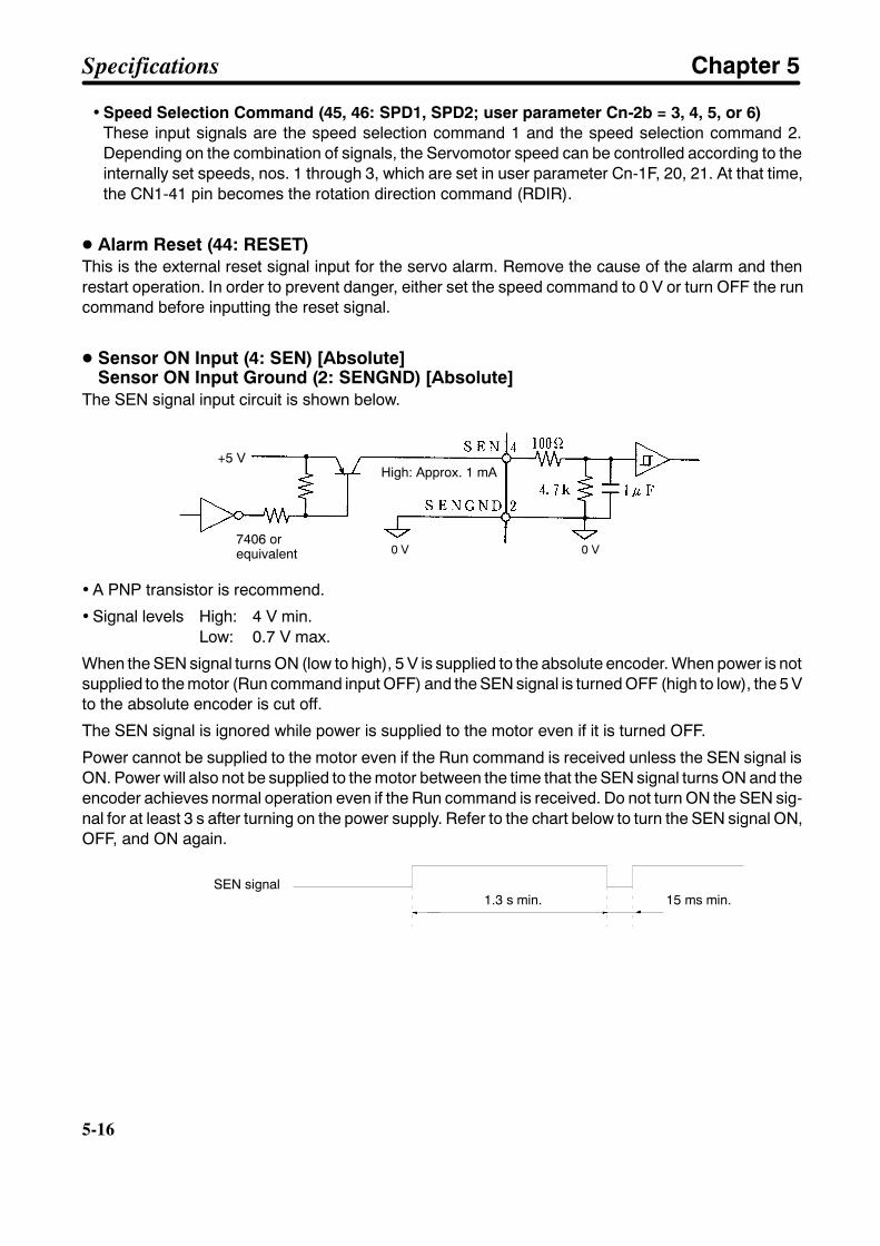
5-16
5-16
• Speed Selection Command (45, 46: SPD1, SPD2; user parameter Cn-2b = 3, 4, 5, or 6)These input signals are the speed selection command 1 and the speed selection command 2.Depending on the combination of signals, the Servomotor speed can be controlled according to theinternally set speeds, nos. 1 through 3, which are set in user parameter Cn-1F, 20, 21. At that time,the CN1-41 pin becomes the rotation direction command (RDIR).
D Alarm Reset (44: RESET)This is the external reset signal input for the servo alarm. Remove the cause of the alarm and thenrestart operation. In order to prevent danger, either set the speed command to 0 V or turn OFF the runcommand before inputting the reset signal.
D Sensor ON Input (4: SEN) [Absolute]Sensor ON Input Ground (2: SENGND) [Absolute]
The SEN signal input circuit is shown below.
7406 orequivalent
High: Approx. 1 mA
0 V 0 V
+5 V
• A PNP transistor is recommend.
• Signal levels High: 4 V min.Low: 0.7 V max.
When the SEN signal turns ON (low to high), 5 V is supplied to the absolute encoder. When power is notsupplied to the motor (Run command input OFF) and the SEN signal is turned OFF (high to low), the 5 Vto the absolute encoder is cut off.
The SEN signal is ignored while power is supplied to the motor even if it is turned OFF.
Power cannot be supplied to the motor even if the Run command is received unless the SEN signal isON. Power will also not be supplied to the motor between the time that the SEN signal turns ON and theencoder achieves normal operation even if the Run command is received. Do not turn ON the SEN sig-nal for at least 3 s after turning on the power supply. Refer to the chart below to turn the SEN signal ON,OFF, and ON again.
SEN signal1.3 s min. 15 ms min.
Specifications Chapter 5
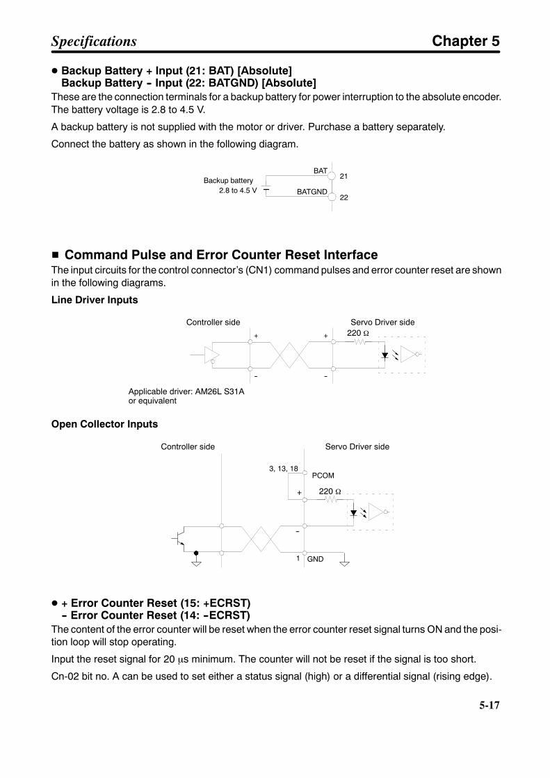
5-17
D Backup Battery + Input (21: BAT) [Absolute]Backup Battery -- Input (22: BATGND) [Absolute]
These are the connection terminals for a backup battery for power interruption to the absolute encoder.The battery voltage is 2.8 to 4.5 V.
A backup battery is not supplied with the motor or driver. Purchase a battery separately.
Connect the battery as shown in the following diagram.
21
22
BAT
BATGND2.8 to 4.5 VBackup battery
H Command Pulse and Error Counter Reset InterfaceThe input circuits for the control connector’s (CN1) command pulses and error counter reset are shownin the following diagrams.
Line Driver Inputs
+
--
+
--
Controller side Servo Driver side
Applicable driver: AM26L S31Aor equivalent
220 Ω
Open Collector Inputs
+
--
220 Ω
GND
PCOM
1
3, 13, 18
Controller side Servo Driver side
D + Error Counter Reset (15: +ECRST)-- Error Counter Reset (14: --ECRST)
The content of the error counter will be reset when the error counter reset signal turns ON and the posi-tion loop will stop operating.
Input the reset signal for 20 µs minimum. The counter will not be reset if the signal is too short.
Cn-02 bit no. A can be used to set either a status signal (high) or a differential signal (rising edge).
Specifications Chapter 5
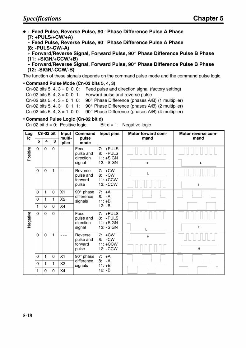
5-18
5-18
D + Feed Pulse, Reverse Pulse, 90_ Phase Difference Pulse A Phase(7: +PULS/+CW/+A)-- Feed Pulse, Reverse Pulse, 90_ Phase Difference Pulse A Phase(8: -PULS/-CW/-A)+ Forward/Reverse Signal, Forward Pulse, 90_ Phase Difference Pulse B Phase(11: +SIGN/+CCW/+B)-- Forward/Reverse Signal, Forward Pulse, 90_ Phase Difference Pulse B Phase(12: -SIGN/-CCW/-B)
The function of these signals depends on the command pulse mode and the command pulse logic.
• Command Pulse Mode (Cn-02 bits 5, 4, 3)Cn-02 bits 5, 4, 3 = 0, 0, 0: Feed pulse and direction signal (factory setting)Cn-02 bits 5, 4, 3 = 0, 0, 1: Forward pulse and reverse pulseCn-02 bits 5, 4, 3 = 0, 1, 0: 90_ Phase Difference (phases A/B) (1 multiplier)Cn-02 bits 5, 4, 3 = 0, 1, 1: 90_ Phase Difference (phases A/B) (2 multiplier)Cn-02 bits 5, 4, 3 = 1, 0, 0: 90_ Phase Difference (phases A/B) (4 multiplier)
• Command Pulse Logic (Cn-02 bit d)Cn-02 bit d = 0: Positive logic; Bit d = 1: Negative logic
Logic
Cn-02 bit Inputmulti-
Commandpulse
Input pins Motor forward com-mand
Motor reverse com-mandic
5 4 3multi-plier
pulsemode
mand mand
Pos
itive 0 0 0 ------ Feed
pulse anddirectionsignal
7: +PULS8: --PULS11: +SIGN12: --SIGN H L
0 0 1 ------ Reversepulse andforwardpulse
7: +CW8: --CW11: +CCW12: --CCW
L
L
0 1 0 X1 90_ phasedifference
7: +A8: --A
0 1 1 X2differencesignals
8: --A11: +B12: --B1 0 0 X4
signals 11: +B12: --B
Neg
ativ
e 0 0 0 ------ Feedpulse anddirectionsignal
7: +PULS8: --PULS11: +SIGN12: --SIGN L
HN
0 0 1 ------ Reversepulse andforwardpulse
7: +CW8: --CW11: +CCW12: --CCW
H
H
0 1 0 X1 90_ phasedifference
7: +A8: --A
0 1 1 X2differencesignals
8: --A11: +B12: --B1 0 0 X4
signals 11: +B12: --B
Specifications Chapter 5
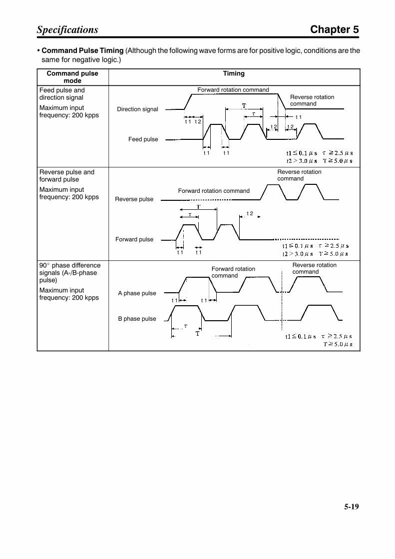
5-19
• Command Pulse Timing (Although the following wave forms are for positive logic, conditions are thesame for negative logic.)
Command pulsemode
Timing
Feed pulse anddirection signal
Maximum inputfrequency: 200 kpps
t 1 t 2t 1
t 2 t 2
t 1 t 1
Direction signal
Feed pulse
Forward rotation commandReverse rotationcommand
Reverse pulse andforward pulse
Maximum inputfrequency: 200 kpps
t 1
t 2
t 1
Reverse pulse
Forward pulse
Forward rotation command
Reverse rotationcommand
90_ phase differencesignals (A-/B-phasepulse)
Maximum inputfrequency: 200 kpps t 1 t 1
A phase pulse
B phase pulse
Forward rotationcommand
Reverse rotationcommand
Specifications Chapter 5
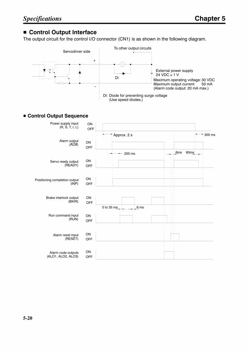
5-20
5-20
H Control Output InterfaceThe output circuit for the control I/O connector (CN1) is as shown in the following diagram.
Di
To other output circuits
Di: Diode for preventing surge voltage(Use speed diodes.)
External power supply24 VDC ± 1 V
Maximum operating voltage: 30 VDCMaximum output current: 50 mA(Alarm code output: 20 mA max.)
+
--
Servodriver side
D Control Output SequencePower supply input
(R, S, T, r, t,)
Alarm output(ALM)
Brake interlock output(BKIR)
Run command input(RUN)
Alarm reset input(RESET)
Alarm code outputs(ALO1, ALO2, ALO3)
ONOFF
ONOFF
ONOFF
ONOFF
ONOFF
ONOFF
ONOFF
ONOFF
6 ms0 to 35 ms
200 ms
300 ms
6ms 60ms
Servo ready output(READY)
Positioning completion output(INP)
Approx. 2 s
Specifications Chapter 5

5-21
D + Speed Conformity (25/27/29: +VCMP), Positioning completion (25/27/29: +INP),Motor Rotation Detection (25/27/29: +TGON), Current Limit Detection (25/27/29:+CLIMT), Brake Interlock (25/27/29: +BKIR), Overload Warning (25/27/29: +OLWRN),Overload Alarm (25/27/29: +OLARM)
-- Speed Conformity (26/28/30: --VCMP), Positioning completion (26/28/30: --INP),Motor Rotation Detection (26/28/30: --TGON), Current Limit Detection (26/28/30:--CLIMT), Brake Interlock (26/28/30: --BKIR), Overload Warning (26/28/30: --OLWRN),Overload Alarm (26/28/30: --OLARM)
The function of the above three pairs of output terminals is determined by the setting of user parameterCn-2d. Any of the available functions can be set to any of the terminal pairs. Each digit in the settingcorresponds to one of the output terminal pairs. A setting of 0 is allowed only for the first digit (CN1 pins25 and 26).
Set Value: 2 1 0
Setting of function for CN1-25, -26
Setting of function for CN1-27, -28
Setting of function for CN1-29, -30
Output signal function Set valuePositioning completion (INP)/Speed conformity (VCMP) 0Motor rotation detection (TGON) 1Servo ready (READY) 2Current Limit Detection (CLIMT) 3Brake Interlock (BKIR) 4Overload Warning (OLWRN) 5Overload Alarm (OLARM) 6
• Speed Conformity (Speed Control Mode)This is output when the speed difference between the speed command and the rotation speed is equalto or less than the value set for the speed conformity signal output range (user parameter Cn-22). Forexample, if the speed command is for 1,000 r/min and the set value is for 50 r/min, it is output in therange from 950 to 1,050 r/min.
• Positioning Completion (Position Control Mode)This is output when the pulse count in the error counter is equal to or less than the positioning comple-tion range (Cn-1b). If the command speed is low speed and the positioning completion range is large,the positioning completion output will remain ON.
• Motor Rotation DetectionOutputs when the motor rotation speed equals or exceeds the value set for user parameter Cn-0b(rotation speed for motor rotation detection).
• Servo ReadyThis signal is output if no errors are detected after powering up the main circuits.
• Current Limit DetectionThe CLIMT signal will turned ON in any of the following 3 cases:
S The output torque reaches the limit value set in user parameter Cn-08 or Cn-09 (the forward andreverse rotation torque limits).
S The forward/reverse rotation current limit (PCL/NCL) is ON and the output torque reaches the limitvalue set in user parameter Cn-18 or Cn-19.
Specifications Chapter 5
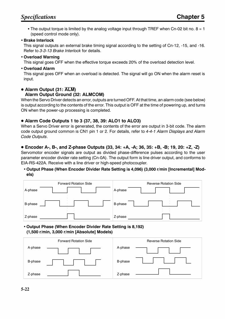
5-22
5-22
S The output torque is limited by the analog voltage input through TREF when Cn-02 bit no. 8 = 1(speed control mode only).
• Brake InterlockThis signal outputs an external brake timing signal according to the setting of Cn-12, -15, and -16.Refer to 3-3-13 Brake Interlock for details.
• Overload WarningThis signal goes OFF when the effective torque exceeds 20% of the overload detection level.
• Overload AlarmThis signal goes OFF when an overload is detected. The signal will go ON when the alarm reset isinput.
D Alarm Output (31: ALM)Alarm Output Ground (32: ALMCOM)
When the Servo Driver detects an error, outputs are turned OFF. At that time, an alarm code (see below)is output according to the contents of the error. This output is OFF at the time of powering up, and turnsON when the power-up processing is completed.
D Alarm Code Outputs 1 to 3 (37, 38, 39: ALO1 to ALO3)When a Servo Driver error is generated, the contents of the error are output in 3-bit code. The alarmcode output ground common is CN1 pin 1 or 2. For details, refer to 4-4-1 Alarm Displays and AlarmCode Outputs.
D Encoder A-, B-, and Z-phase Outputs (33, 34: +A, -A; 36, 35: +B, -B; 19, 20: +Z, -Z)Servomotor encoder signals are output as divided phase-difference pulses according to the userparameter encoder divider rate setting (Cn-0A). The output form is line driver output, and conforms toEIA-RS-422A. Receive with a line driver or high-speed photocoupler.
• Output Phase (When Encoder Divider Rate Setting is 4,096) (3,000 r/min [Incremental] Mod-els)
Forward Rotation Side
A-phase
B-phase
Z-phase
A-phase
B-phase
Z-phase
Reverse Rotation Side
• Output Phase (When Encoder Divider Rate Setting is 8,192)(1,500 r/min, 3,000 r/min [Absolute] Models)
Forward Rotation Side
A-phase
B-phase
Z-phase
A-phase
B-phase
Z-phase
Reverse Rotation Side
Specifications Chapter 5

5-23
Note 1. The Z and A phases are synced, but the pulse width can be shorter than phase A.
Note 2. Absolute data is first output from phase A as serial data when the SEN signal goes ON (low tohigh) and then it is output as the initial incremental pulses A and B (90_ phase differencepulse). Finally, the same output operation as for a normal incremental corder (90_ phase dif-ference pulse) is carried out.
Note 3. The normal incremental encoder signals (phases A and B) are output approximately 400 msafter the SEN signal is input.
• Output Circuit and Receiving Circuit [Incremental]
CN1-33
34
36
35
19
20
1
500 V
FG
+A
--A
+B
--B
+Z
--Z
GND
FG
+A
--A
+B
--B
+Z
--Z
GND
R
R
R
2
1
6
7
10
9
0 V
FG
163
4
5
8
12
11
+5 V
Servo Driver
A-phase
B-phase
Z-phaseOutput line driverSN75ALS194NS or equivalent
Controller on User’s Side
0 V
Applicable line receiverTI-SN75175/MC3486/AM26LS32R: 220 Ω to 470 Ω
A-phase
B-phase
Z-phase
Note Pin No. 50 is open for models conforming to the EC Directives. Connect the cable shield to theconnector case and ground it directly using a clamp.
Specifications Chapter 5

5-24
5-24
H Control I/O Signal Connections and External Signal Processing forPositioning Control
24 VDCLine driver outputEIA-RS422Aconforming(Load resistance:200 Ω max.)
+24 VIN
Maximum operatingvoltage: 30 VDCMaximum outputcurrent: 50 mA
Maximum operatingvoltage: 30 VDCMaximum outputcurrent: 20 mA
Run command
Gaindeceleration
Forward rotationdrive prohibit
Alarm reset
Forward rotationcurrent limit
Reverse rotationcurrent limit
Do not connectthese pins
Reversepulse
Forwardpulse
Errorcounterreset
Current monitor(2 V/rated torque)Speed monitor(1 V/(1,000 r/min))
Reverse rotationdrive prohibit
Ground common
Positioningcompletion
Servo ready
Alarm output
Alarm codeoutputs
Encoder A, B, andZ phase outputs
18
Note Pin No. 50 is open for modelsconforming to the EC Direc-tives. Connect the cableshield to the connector caseand ground it directly using aclamp.
Frame ground
Specifications Chapter 5
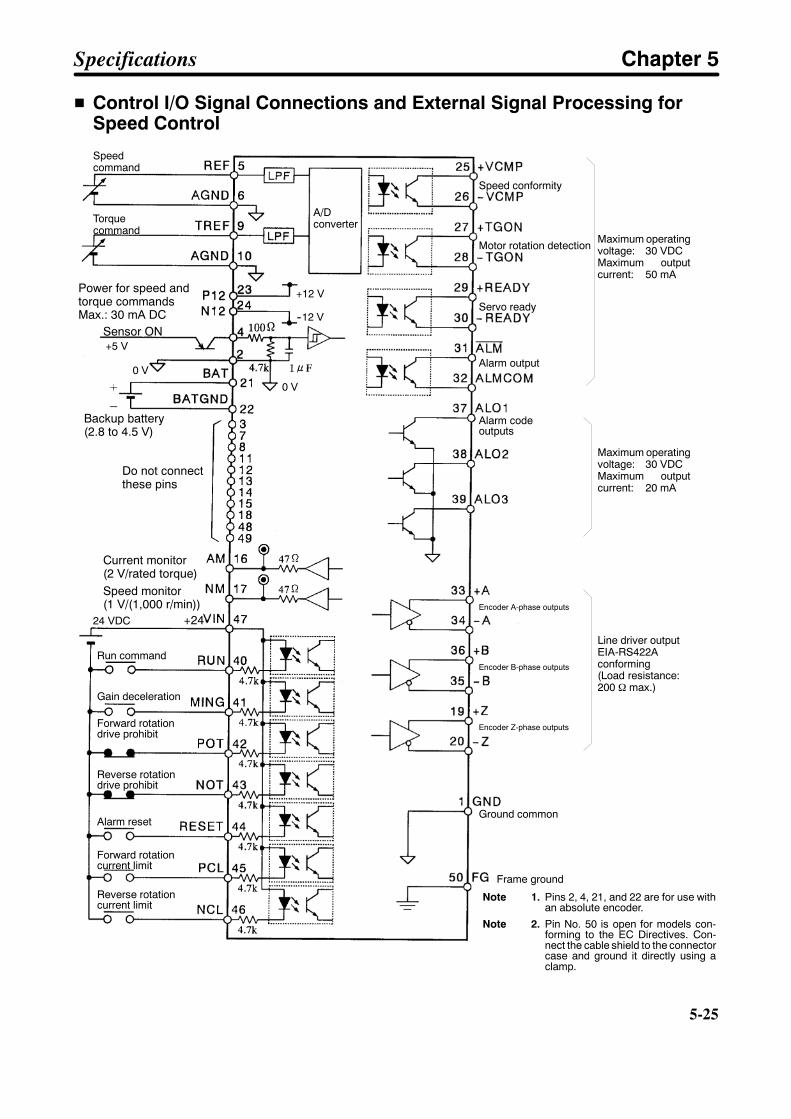
5-25
H Control I/O Signal Connections and External Signal Processing forSpeed Control
Speed conformity
Motor rotation detection
Alarm output
Alarm codeoutputs
Encoder A-phase outputs
Encoder B-phase outputs
Encoder Z-phase outputs
Ground common
Run command
Gain deceleration
Forward rotationdrive prohibit
Reverse rotationdrive prohibit
Alarm reset
Forward rotationcurrent limit
Reverse rotationcurrent limit
Speedcommand
Torquecommand
Maximum operatingvoltage: 30 VDCMaximum outputcurrent: 20 mA
Line driver outputEIA-RS422Aconforming(Load resistance:200 Ω max.)
Maximum operatingvoltage: 30 VDCMaximum outputcurrent: 50 mA
+2424 VDC
0 V
+5 V
+12 V
--12 V
0 V
A/Dconverter
Power for speed andtorque commandsMax.: 30 mA DC
Sensor ON
Backup battery(2.8 to 4.5 V)
Do not connectthese pins
Current monitor(2 V/rated torque)Speed monitor(1 V/(1,000 r/min))
Servo ready
Note 1. Pins 2, 4, 21, and 22 are for use withan absolute encoder.
Note 2. Pin No. 50 is open for models con-forming to the EC Directives. Con-nect the cable shield to the connectorcase and ground it directly using aclamp.
Frame ground
Specifications Chapter 5
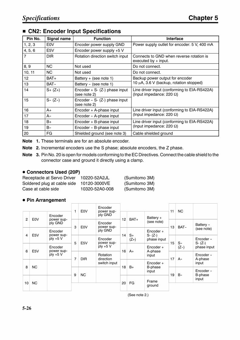
5-26
5-26
H CN2: Encoder Input SpecificationsPin No. Signal name Function Interface
1, 2, 3 E0V Encoder power supply GND Power supply outlet for encoder: 5 V, 400 mA4, 5, 6 E5V Encoder power supply +5 V
Power supply outlet for encoder: 5 V, 400 mA
7 DIR Rotation direction switch input Connects to GND when reverse rotation isexecuted by + input.
8, 9 NC Not used Do not connect.10, 11 NC Not used Do not connect.12 BAT+ Battery + (see note 1) Backup power output for encoder
10 µA, 3.6 V (backup, rotation stopped)13 BAT-- Battery -- (see note 1)Backup power output for encoder10 µA, 3.6 V (backup, rotation stopped)
14 S+ (Z+) Encoder + S- (Z-) phase input(see note 2)
Line driver input (conforming to EIA-RS422A)(Input impedance: 220 Ω)
15 S-- (Z--) Encoder -- S- (Z-) phase input(see note 2)
(Input impedance: 220 Ω)
16 A+ Encoder + A-phase input Line driver input (conforming to EIA-RS422A)(Input impedance: 220 Ω)17 A-- Encoder -- A-phase inputLine driver input (conforming to EIA-RS422A)(Input impedance: 220 Ω)
18 B+ Encoder + B-phase input Line driver input (conforming to EIA-RS422A)(Input impedance: 220 Ω)19 B-- Encoder -- B-phase inputLine driver input (conforming to EIA-RS422A)(Input impedance: 220 Ω)
20 FG Shielded ground (see note 3) Cable shielded ground
Note 1. These terminals are for an absolute encoder.
Note 2. Incremental encoders use the S phase; absolute encoders, the Z phase.
Note 3. Pin No. 20 is open for models conforming to the EC Directives. Connect the cable shield to theconnector case and ground it directly using a clamp.
D Connectors Used (20P)Receptacle at Servo Driver 10220-52A2JL (Sumitomo 3M)Soldered plug at cable side 10120-3000VE (Sumitomo 3M)Case at cable side 10320-52A0-008 (Sumitomo 3M)
D Pin Arrangement
2 E0V
4 E5V
8
10 NC
1 E0V
3 E0V
7 DIR
9
12
14 S+(Z+)
16 A+
11 NC
13
17 A--
15 S--(Z--)
6 E5V
5 E5V
18 B+
20 FG
19 B--
Encoderpower sup-ply GND
Encoderpower sup-ply +5 V
Encoderpower sup-ply +5 V
Encoderpower sup-ply GND
Encoderpower sup-ply +5 V
Encoderpower sup-ply GND
Rotationdirectionswitch input
Encoder +S- (Z-)phase input
Encoder +A-phaseinput
Encoder +B-phaseinput
Frameground
Encoder --S- (Z-)phase input
Encoder --A-phaseinput
Encoder --B-phaseinput
NC
NC
BAT+
BAT--
Battery +(see note)
Battery --(see note)
(See note 2.)
Specifications Chapter 5
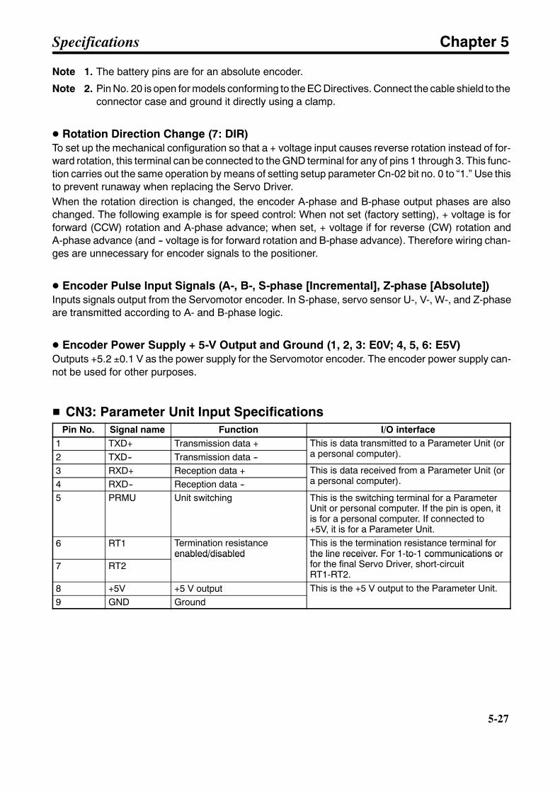
5-27
Note 1. The battery pins are for an absolute encoder.
Note 2. Pin No. 20 is open for models conforming to the EC Directives. Connect the cable shield to theconnector case and ground it directly using a clamp.
D Rotation Direction Change (7: DIR)To set up the mechanical configuration so that a + voltage input causes reverse rotation instead of for-ward rotation, this terminal can be connected to the GND terminal for any of pins 1 through 3. This func-tion carries out the same operation by means of setting setup parameter Cn-02 bit no. 0 to “1.” Use thisto prevent runaway when replacing the Servo Driver.When the rotation direction is changed, the encoder A-phase and B-phase output phases are alsochanged. The following example is for speed control: When not set (factory setting), + voltage is forforward (CCW) rotation and A-phase advance; when set, + voltage if for reverse (CW) rotation andA-phase advance (and -- voltage is for forward rotation and B-phase advance). Therefore wiring chan-ges are unnecessary for encoder signals to the positioner.
D Encoder Pulse Input Signals (A-, B-, S-phase [Incremental], Z-phase [Absolute])Inputs signals output from the Servomotor encoder. In S-phase, servo sensor U-, V-, W-, and Z-phaseare transmitted according to A- and B-phase logic.
D Encoder Power Supply + 5-V Output and Ground (1, 2, 3: E0V; 4, 5, 6: E5V)Outputs +5.2 ±0.1 V as the power supply for the Servomotor encoder. The encoder power supply can-not be used for other purposes.
H CN3: Parameter Unit Input SpecificationsPin No. Signal name Function I/O interface
1 TXD+ Transmission data + This is data transmitted to a Parameter Unit (ora personal computer).2 TXD-- Transmission data --This is data transmitted to a Parameter Unit (ora personal computer).
3 RXD+ Reception data + This is data received from a Parameter Unit (ora personal computer).4 RXD-- Reception data --This is data received from a Parameter Unit (ora personal computer).
5 PRMU Unit switching This is the switching terminal for a ParameterUnit or personal computer. If the pin is open, itis for a personal computer. If connected to+5V, it is for a Parameter Unit.
6 RT1 Termination resistanceenabled/disabled
This is the termination resistance terminal forthe line receiver. For 1-to-1 communications orfor the final Servo Driver, short-circuit7 RT2
enabled/disabled the line receiver. For 1-to-1 communications orfor the final Servo Driver, short-circuitRT1-RT2.
8 +5V +5 V output This is the +5 V output to the Parameter Unit.9 GND Ground
This is the +5 V output to the Parameter Unit.
Specifications Chapter 5
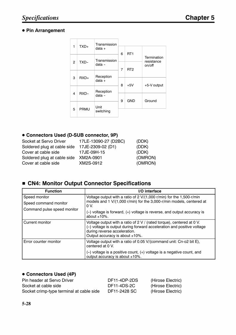
5-28
5-28
D Pin Arrangement
1 TXD+
2 TXD--
5 PRMU
6 RT1
7 RT2
9 GND
3 RXD+
8 +5V
4 RXD--
Transmissiondata +
Transmissiondata --
Receptiondata +
Receptiondata --
Unitswitching
Terminationresistanceon/off
+5-V output
Ground
D Connectors Used (D-SUB connector, 9P)Socket at Servo Driver 17LE-13090-27 (D2BC) (DDK)Soldered plug at cable side 17JE-2309-02 (D1) (DDK)Cover at cable side 17JE-09H-15 (DDK)Soldered plug at cable side XM2A-0901 (OMRON)Cover at cable side XM2S-0912 (OMRON)
H CN4: Monitor Output Connector SpecificationsFunction I/O interface
Speed monitor
Speed command monitor
Command pulse speed monitor
Voltage output with a ratio of 2 V/(1,000 r/min) for the 1,500-r/minmodels and 1 V/(1,000 r/min) for the 3,000-r/min models, centered at0 V.
(--) voltage is forward, (+) voltage is reverse, and output accuracy isabout ±10%.
Current monitor Voltage output with a ratio of 2 V / (rated torque), centered at 0 V.(--) voltage is output during forward acceleration and positive voltageduring reverse acceleration.Output accuracy is about ±10%.
Error counter monitor Voltage output with a ratio of 0.05 V/(command unit: Cn-o2 bit E),centered at 0 V.
(--) voltage is a positive count, (+) voltage is a negative count, andoutput accuracy is about ±10%.
D Connectors Used (4P)Pin header at Servo Driver DF11-4DP-2DS (Hirose Electric)Socket at cable side DF11-4DS-2C (Hirose Electric)Socket crimp-type terminal at cable side DF11-2428 SC (Hirose Electric)
Specifications Chapter 5

5-29
5-1-4 ParametersRefer to 3-3-2 Setting and Checking User Parameters (Cn-03 to 2d) for a table of user parameters.
D Speed Command Scale: Cn-03 (Speed, Torque)This is a constant for adjusting the motor rotation speed for the speed command input. The adjustablerange is 10 to 2,000 (r/min/V). The factory setting is for 300 (r/min/V), with an input voltage of 5 V at1,500 r/min.
Rotation speed(r/min)
Setting at timeof shipping
Speed command input voltage (V)
3,000 r/min6V
3,000 r/min10V
When a position control loop is formed for a speed command type, this speed command scale becomesthe position loop gain.
Specifications Chapter 5

5-30
5-30
D Speed Loop Gain: Cn-04 (Position, Speed)This is the proportional gain for the speed controller. The adjustable range is 1 to 2,000 Hz (the responsefrequency when equivalent inertia is used). As the number is increased, the gain is increased.
The factory setting is for 80 (Hz). Using the factory setting for the Servomotor alone or with a small loadinertia will cause vibration to occur, so set the value to a maximum of 20 (Hz) for operation.
D Speed Loop Integration Time Constant: Cn-05 (Position, Speed)This is the integration time for the speed controller. The adjustable range is 200 to 51,200 (0.01 ms), andit is factory set to 2,000. As the number is increased, the gain is increased.
D Emergency Stop Torque: Cn-06 (Position, Speed)When setup parameter Cn-01 bit no. 8 = 1, this sets the braking torque for over-travel stopping (forward/reverse drive prohibit input operation). The setting range is 0% to 350% of maximum torque (a percent-age of the braking torque as 100% of the Servomotor rated torque). The factory setting is for 350% of themaximum torque.
D Soft Start Acceleration Time: Cn-07 (Speed)Soft Start Deceleration Time: Cn-23 (Speed)
The Servomotor rotation acceleration time from 0 r/min to maximum instantaneous revolution is set inCn-07, and the deceleration time from maximum instantaneous revolution to 0 r/min is set in Cn-23. Thefactory setting is for 0 (ms).
Set to 0 (ms) when positioning is controlled by connecting a positioner with an acceleration function orwhen the speed control mode is not being used.
Set both the acceleration and deceleration times when using these functions.
D Forward Rotation Torque Control: Cn-08 (Position, Speed, Torque)Reverse Rotation Torque Control: Cn-09 (Position, Speed, Torque)
The Servomotor output torque control value for forward rotation is sen in Cn-08, and the value forreverse rotation is set in Cn-09. The setting range is 0% to 350% of the maximum torque, and the factorysetting is for 350% of the maximum torque.
D Encoder Dividing Rate Setting: Cn-0A (Position, Speed, Torque)The number of pulses detected (A- and B-pulses) per encoder revolution is converted to the number ofpulses set for this parameter and output from the Servo Driver. The setting range is 16 to 8,192 pulses/revolution, and the factory setting is for 1,000 (pulses/revolution).
The upper limit of the setting range is 8,192 for 1,500-r/min models and 4,096 for 3,000-r/min models.
D Rotation Speed for Servomotor Rotation Detection: Cn-0b (Position, Speed,Torque)
This sets the rotation speed for detecting whether or not the Servomotor is rotating. The setting range is1 to 4,500 r/min. When motor rotation detection has been set for the output signal switch (Cn-2d = 1), theServomotor rotation detection output (TGON) is turned ON if the Servomotor rotational speed meets orexceeds this set value. The factory setting is for 20 (r/min).
The upper limit of the setting range is 3,000 for 1,500-r/min models and 4,500 for 3,000-r/min models.
Specifications Chapter 5
5-31
D P Control Switching (Torque Command): Cn-0C (Position, Speed)P Control Switching (Speed Command): Cn-0d (Position, Speed)P Control Switching (Acceleration Command): Cn-0E (Position, Speed)P Control Switching (Error Pulse): Cn-0F (Position)
These set the various points for switching the speed controller from PI control to P control in order tomoderate excessive characteristics when an operation such as acceleration or deceleration isexecuted accompanied by output saturation of the controller. These parameters are enabled by settingthe P control switching selection (Cn-01 bit b) to 1. The selections are made by setting the setup param-eter Cn-01 bit nos. d and C.P Control Switching (Torque Command) is set between 0% and 350% as a percentage of the ratedtorque. The factory setting is 200%.P Control Switching (Speed Command) is set between 0 and 4,500 r/min. The upper limit of the settingrange is 3,000 for 1,500-r/min models and 4,500 for 3,000-r/min models. The factory setting is 0.P Control Switching (Acceleration Command) is set between 0 and 3,000 in units of 10 (r/min)/s. Thefactory setting is 0.P Control Switching (error pulse) is set between 0 and 10,000 in command units. The factory setting is10.
D Jog Speed: Cn-10 (Position, Speed, Torque)This sets the speed for manual operation. The setting range is 0 to 4,500 r/min. The upper limit of thesetting range is 3,000 for 1,500-r/min models and 4,500 for 3,000-r/min models. During manual opera-tion, operating commands are given from the Parameter Unit. The factory setting is for 500 (r/min).
D Number of Encoder Pulses: Cn-11 (Position, Speed, Torque)This sets the number of pulses per revolution of a connected encoder. The setting is either 8,192 for1,500-r/min models or 4,096 for 3,000-r/min models. The Servomotor might not operate correctly if anyother values are used. The factory setting is for 8,192 (pulses/revolution).
D Brake Timing 1: Cn-12 (Position, Speed, Torque)Brake Command Speed: Cn-15 (Position, Speed, Torque)Brake Timing 2: Cn-16 (Position, Speed, Torque)
These parameters set the output timing for the brake interlock signal (BKIR), which turns the electro-magnetic brake ON and OFF. The settings are enabled when the brake interlock is set in the outputsignal selection (Cn-2d = 4).Brake timing 1 is a parameter for Servomotors with brakes, and it sets the delay time from the time ofbrake interlock output (BKIR) until the servo turns off. The setting range is 0 to 50 (× 10 ms), and thefactory setting is for 0 (× 10 ms).When setting the brake timing, the time when the servo turns off until the brake interlock is set to off is setas the holding time.If the run command turns off, a servo error occurs, or the main-circuit power supply turns off duringoperation of a Servomotor with a brake, the dynamic brake comes on (setup parameter Cn-01 bit no. 6 =0) and Servomotor rotation speed is decreased. When the speed drops to the level of the value set forthe brake command speed (Cn-15), the brake interlock output (BKIR) turns OFF.Even if the speed does not drop to the level of the value set for the brake command speed (Cn-15), thebrake interlock output (BKIR) turns OFF after the time set for brake timing 2 has elapsed. (This timesetting is made for the purpose of preventing damage to machinery or the Servomotor holding brake.)The setting range is 10 to 100 (× 10 ms), and the factory setting is for 50 (× 10 ms).
Specifications Chapter 5
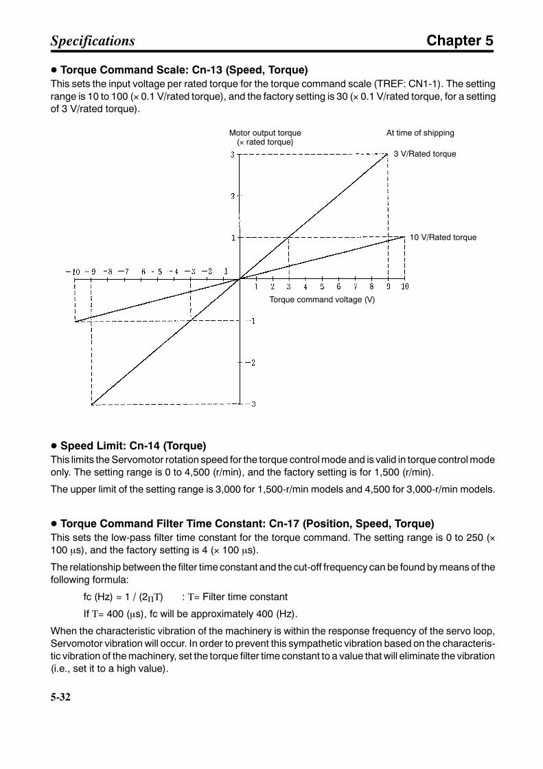
5-32
5-32
D Torque Command Scale: Cn-13 (Speed, Torque)This sets the input voltage per rated torque for the torque command scale (TREF: CN1-1). The settingrange is 10 to 100 (× 0.1 V/rated torque), and the factory setting is 30 (× 0.1 V/rated torque, for a settingof 3 V/rated torque).
Motor output torque(× rated torque)
At time of shipping
3 V/Rated torque
Torque command voltage (V)
10 V/Rated torque
D Speed Limit: Cn-14 (Torque)This limits the Servomotor rotation speed for the torque control mode and is valid in torque control modeonly. The setting range is 0 to 4,500 (r/min), and the factory setting is for 1,500 (r/min).
The upper limit of the setting range is 3,000 for 1,500-r/min models and 4,500 for 3,000-r/min models.
D Torque Command Filter Time Constant: Cn-17 (Position, Speed, Torque)This sets the low-pass filter time constant for the torque command. The setting range is 0 to 250 (×100 µs), and the factory setting is 4 (× 100 µs).
The relationship between the filter time constant and the cut-off frequency can be found by means of thefollowing formula:
fc (Hz) = 1 / (2ΠΤ) : Τ= Filter time constant
If Τ= 400 (µs), fc will be approximately 400 (Hz).
When the characteristic vibration of the machinery is within the response frequency of the servo loop,Servomotor vibration will occur. In order to prevent this sympathetic vibration based on the characteris-tic vibration of the machinery, set the torque filter time constant to a value that will eliminate the vibration(i.e., set it to a high value).
Specifications Chapter 5
5-33
D Forward Rotation External Current Limit: Cn-18 (Position, Speed, Torque)Reverse Rotation External Current Limit: Cn-19 (Position, Speed, Torque)
These set the Servomotor output torque limits for the forward and reverse directions. The are validwhen when the forward/reverse current limits (PCL/NCL) are input. This function can’t be used whenthe control mode is “internal speed control settings.” The setting range is 0% to 350% of the maximumtorque, and the factory setting is for the 100 (%).
D Position Loop Gain: Cn-1A (Position, Speed)It is valid for position control and position lock status. The setting range is 1 to 1,000 (1/s), and the factorysetting is 40 (1/s). Set to between 50 and 70 for general NC machine tools, to between 30 and 50 forgeneral-purpose machine assembly machines, and to between 10 and 30 for industrial robots. If theposition loop gain is set too high for systems with low machine hardness or for systems with low inheritvibrations, machine resonance can result, causing an overload alarm.
D Positioning Completion Range: Cn-1b (Position)This sets the error counter value for outputting the positioning completion signal (INP). The positioningcompletion output will be ON when the error counter is at or below this value.
The setting range is 0 to 250 in command units and the factory setting is 3.
D Bias Rotational Speed: Cn-1C (Position)This is the position control bias setting. It can be used according to the load conditions to reduce thepositioning time.
The setting range is 0 to 450 in r/min and the factory setting is 0.
D Feed-forward Amount: Cn-1d (Position)This is the compensation value for position control feed-forward. Positioning time is reduced by addingthe differential of the command pulse to the speed command.
The setting range is 0% to 100% and the factory setting is 0%.
D Error Counter Over Level: Cn-1E (Position)This is the setting for detection level for error counter overrun. A servo alarm will be generated if the errorcounter exceeds this value.
The setting range is 1 to 32,767 in x256 command units and the factory setting is 1,024.
D No. 1 Internal Speed Setting: Cn-1F (Factory Setting: 100 r/min) (Speed)No. 2 Internal Speed Setting: Cn-20 (Factory Setting: 200 r/min) (Speed)No. 3 Internal Speed Setting: Cn-21 (Factory Setting: 300 r/min) (Speed)
Make these settings to control speeds by means of internal settings. The setting range is 0 to 4,500(r/min). The upper limit of the setting range is 3,000 for 1,500-r/min models and 4,500 for 3,000-r/minmodels. For details, refer to 3-3-4 Setting Internal Speed Control.
D Speed Conformity Signal Output Range: Cn-22 (Speed)When the absolute value of the difference between the speed command and the Servomotor rotationspeed (the speed deviation) is equal to or less than the set value, the speed conformity output (VCMP)turns ON. This parameter is valid in the speed control mode when the speed conformity output is set forthe output signal selection. (Cn-2d = 0)
Specifications Chapter 5

5-34
5-34
If the speed command is for 1,000 (r/min) and the speed conformity signal output range is 100 (r/min),then the speed conformity output (VCMP) turns ON when the Servomotor rotation speed is between900 (r/min) and 1,100 (r/min). The setting range is 0 to 100 (r/min), and the factory setting is for 10(r/min).
D Electronic Gear Ratio G1 (Numerator): Cn-24 (Position)Electronic Gear Ratio G2 (Denominator): Cn-25 (Position)
The motor will rotate via the pulse obtained by multiplying the command pulses by the electronic gearratio G1/G2. The setting ranges for G1 and G2 are 1 to 65,535, but (1/100) (G1/G2) 100. Thefactory setting is 4/1, meaning that the motor will rotate once for each 8,192 (1,500-r/min models) or4,096 (3,000-r/min models) pulses.
D Position Command Acceleration/Deceleration Constant: Cn-26 (Position)This parameter can be used to perform smoothing processing on the command pulses to rotate themotor. This can be effective in the following cases.
• There is no acceleration or deceleration in the command pulses.
• The frequency of the command pulses varies rapidly.
• The electronic gear ratio is large (G1/G2 10)
The setting range is 0 to 640 in 0.1 ms units and the factory setting is 0.
D Feed-forward Command Filter: Cn-27 (Position)This setting is for a low pass filter to prevent feed-forward amounts from being rapidly added. Over-shooting can be prevented by using this setting when the command pulse frequency varies rapidly.
The setting range is 0 to 640 in 0.1 ms units and the factory setting is 0.
D Compensating Gain: Cn-28 (Position, Speed)When outputting a large torque (during acceleration, deceleration, etc.), the speed loop gain isdecreased based on this setting. Motor vibration can be reduced by increasing this setting; also, thepositioning time can be reduced because the speed loop gain can be set to a higher value.
A compensation gain adjustment is possible only after adjusting the speed loop gain with Cn-04 and thespeed loop integral time constant with Cn-05.
The upper-limit value of the compensation gain may be 100 or less according to the speed loop gain setwith Cn-04 and the speed loop integral time constant set with Cn-05, in which case an error will result ifthe compensation gain is set to a value exceeding the upper-limit value.
Make sure that Cn-28 is set to zero before executing auto-tuning, otherwise normal gain adjustmentsmay not be possible.
If this setting is too high, follow-up delays can occur during acceleration and deceleration. The settingrange is 0 to 100, and the factory setting is 0.
D Rotation Speed for Position Lock: Cn-29 (Speed)This sets the rotation speed for position locks, and is enabled when the control mode selection (Cn-2b)is set to 10 (position lock speed control). If the motor reaches or falls below the set speed when theposition lock command input (PLOCK) is ON, the system will be changed from speed control to positioncontrol and the motor will servo-lock. The position lock force is adjusted via the position loop gain(Cn-1A).
Specifications Chapter 5
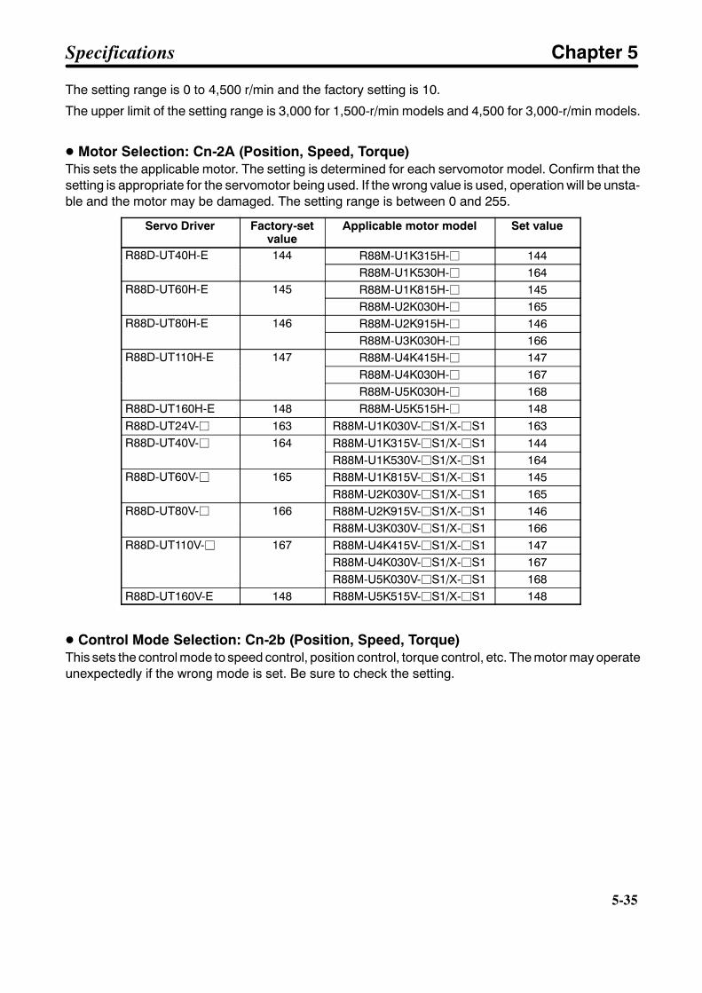
5-35
The setting range is 0 to 4,500 r/min and the factory setting is 10.
The upper limit of the setting range is 3,000 for 1,500-r/min models and 4,500 for 3,000-r/min models.
D Motor Selection: Cn-2A (Position, Speed, Torque)This sets the applicable motor. The setting is determined for each servomotor model. Confirm that thesetting is appropriate for the servomotor being used. If the wrong value is used, operation will be unsta-ble and the motor may be damaged. The setting range is between 0 and 255.
Servo Driver Factory-setvalue
Applicable motor model Set value
R88D-UT40H-E 144 R88M-U1K315H-j 144R88D-UT40H-E 144R88M-U1K530H-j 164
R88D-UT60H-E 145 R88M-U1K815H-j 145R88D-UT60H-E 145R88M-U2K030H-j 165
R88D-UT80H-E 146 R88M-U2K915H-j 146R88D-UT80H-E 146R88M-U3K030H-j 166
R88D-UT110H-E 147 R88M-U4K415H-j 147R88D-UT110H-E 147R88M-U4K030H-j 167R88M-U5K030H-j 168
R88D-UT160H-E 148 R88M-U5K515H-j 148R88D-UT24V-j 163 R88M-U1K030V-jS1/X-jS1 163R88D-UT40V-j 164 R88M-U1K315V-jS1/X-jS1 144R88D-UT40V-j 164
R88M-U1K530V-jS1/X-jS1 164R88D-UT60V-j 165 R88M-U1K815V-jS1/X-jS1 145R88D-UT60V-j 165
R88M-U2K030V-jS1/X-jS1 165R88D-UT80V-j 166 R88M-U2K915V-jS1/X-jS1 146R88D-UT80V-j 166
R88M-U3K030V-jS1/X-jS1 166R88D-UT110V-j 167 R88M-U4K415V-jS1/X-jS1 147R88D-UT110V-j 167
R88M-U4K030V-jS1/X-jS1 167R88M-U5K030V-jS1/X-jS1 168
R88D-UT160V-E 148 R88M-U5K515V-jS1/X-jS1 148
D Control Mode Selection: Cn-2b (Position, Speed, Torque)This sets the control mode to speed control, position control, torque control, etc. The motor may operateunexpectedly if the wrong mode is set. Be sure to check the setting.
Specifications Chapter 5
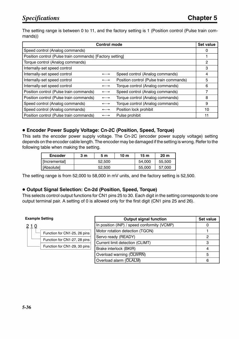
5-36
5-36
The setting range is between 0 to 11, and the factory setting is 1 (Position control (Pulse train com-mands))
Control mode Set valueSpeed control (Analog commands) 0Position control (Pulse train commands) [Factory setting] 1Torque control (Analog commands) 2Internally-set speed control 3Internally-set speed control ←→ Speed control (Analog commands) 4Internally-set speed control ←→ Position control (Pulse train commands) 5Internally-set speed control ←→ Torque control (Analog commands) 6Position control (Pulse train commands) ←→ Speed control (Analog commands) 7Position control (Pulse train commands) ←→ Torque control (Analog commands) 8Speed control (Analog commands) ←→ Torque control (Analog commands) 9Speed control (Analog commands) ←→ Position lock prohibit 10Position control (Pulse train commands) ←→ Pulse prohibit 11
D Encoder Power Supply Voltage: Cn-2C (Position, Speed, Torque)This sets the encoder power supply voltage. The Cn-2C (encoder power supply voltage) settingdepends on the encoder cable length. The encoder may be damaged if the setting is wrong. Refer to thefollowing table when making the setting.
Encoder 3 m 5 m 10 m 15 m 20 m[Incremental] 52,500 54,000 55,500[Absolute] 52,500 55,000 57,000
The setting range is from 52,000 to 58,000 in mV units, and the factory setting is 52,500.
D Output Signal Selection: Cn-2d (Position, Speed, Torque)This selects control output functions for CN1 pins 25 to 30. Each digit in the setting corresponds to oneoutput terminal pair. A setting of 0 is allowed only for the first digit (CN1 pins 25 and 26).
Output signal function Set valueIn position (INP) / speed conformity (VCMP) 0Motor rotation detection (TGON) 1Servo ready (READY) 2Current limit detection (CLIMT) 3Brake interlock (BKIR) 4Overload warning (OLWRN) 5Overload alarm (OLALM) 6
Example Setting
2 1 0Function for CN1-25, 26 pins
Function for CN1-27, 28 pins
Function for CN1-29, 30 pins
Specifications Chapter 5
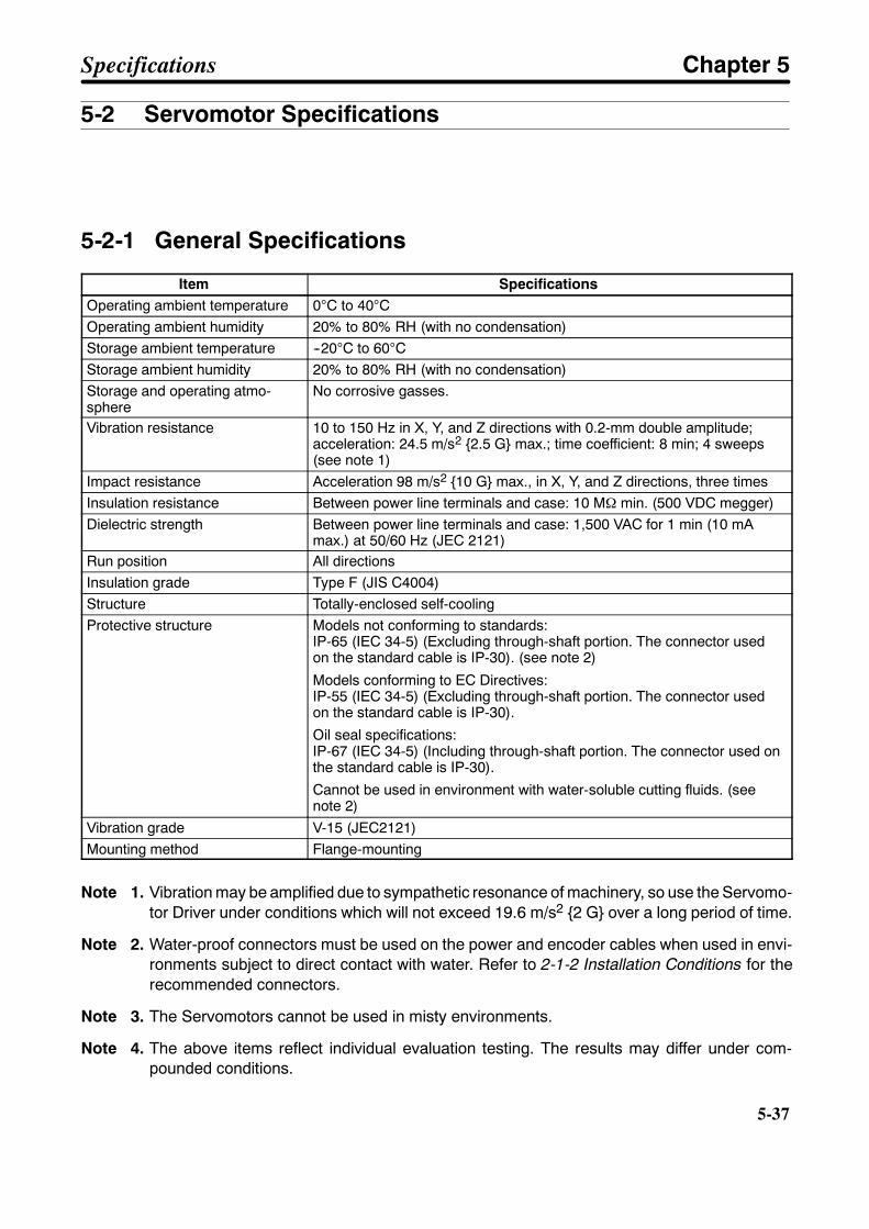
5-37
5-2 Servomotor Specifications
5-2-1 General Specifications
Item SpecificationsOperating ambient temperature 0°C to 40°COperating ambient humidity 20% to 80% RH (with no condensation)Storage ambient temperature --20°C to 60°CStorage ambient humidity 20% to 80% RH (with no condensation)Storage and operating atmo-sphere
No corrosive gasses.
Vibration resistance 10 to 150 Hz in X, Y, and Z directions with 0.2-mm double amplitude;acceleration: 24.5 m/s2 2.5 G max.; time coefficient: 8 min; 4 sweeps(see note 1)
Impact resistance Acceleration 98 m/s2 10 G max., in X, Y, and Z directions, three timesInsulation resistance Between power line terminals and case: 10 MΩ min. (500 VDC megger)Dielectric strength Between power line terminals and case: 1,500 VAC for 1 min (10 mA
max.) at 50/60 Hz (JEC 2121)Run position All directionsInsulation grade Type F (JIS C4004)Structure Totally-enclosed self-coolingProtective structure Models not conforming to standards:
IP-65 (IEC 34-5) (Excluding through-shaft portion. The connector usedon the standard cable is IP-30). (see note 2)
Models conforming to EC Directives:IP-55 (IEC 34-5) (Excluding through-shaft portion. The connector usedon the standard cable is IP-30).
Oil seal specifications:IP-67 (IEC 34-5) (Including through-shaft portion. The connector used onthe standard cable is IP-30).
Cannot be used in environment with water-soluble cutting fluids. (seenote 2)
Vibration grade V-15 (JEC2121)Mounting method Flange-mounting
Note 1. Vibration may be amplified due to sympathetic resonance of machinery, so use the Servomo-tor Driver under conditions which will not exceed 19.6 m/s2 2 G over a long period of time.
Note 2. Water-proof connectors must be used on the power and encoder cables when used in envi-ronments subject to direct contact with water. Refer to 2-1-2 Installation Conditions for therecommended connectors.
Note 3. The Servomotors cannot be used in misty environments.
Note 4. The above items reflect individual evaluation testing. The results may differ under com-pounded conditions.
Specifications Chapter 5
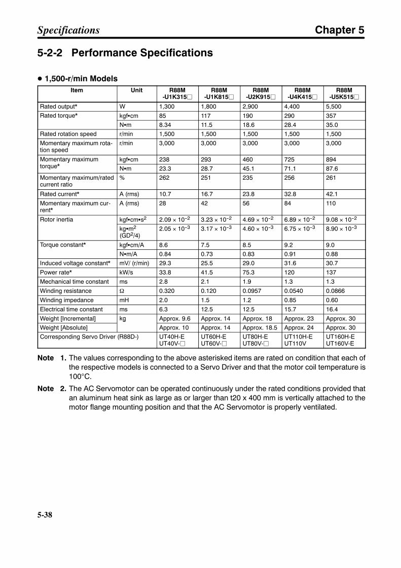
5-38
5-38
5-2-2 Performance Specifications
D 1,500-r/min ModelsItem Unit R88M
-U1K315jR88M
-U1K815jR88M
-U2K915jR88M
-U4K415jR88M
-U5K515j
Rated output* W 1,300 1,800 2,900 4,400 5,500Rated torque* kgfScm 85 117 190 290 357Rated torque*
NSm 8.34 11.5 18.6 28.4 35.0Rated rotation speed r/min 1,500 1,500 1,500 1,500 1,500
Momentary maximum rota-tion speed
r/min 3,000 3,000 3,000 3,000 3,000
Momentary maximumtorque*
kgfScm 238 293 460 725 894Momentary maximumtorque* NSm 23.3 28.7 45.1 71.1 87.6Momentary maximum/ratedcurrent ratio
% 262 251 235 256 261
Rated current* A (rms) 10.7 16.7 23.8 32.8 42.1
Momentary maximum cur-rent*
A (rms) 28 42 56 84 110
Rotor inertia kgfScmSs2 2.09 × 10--2 3.23 × 10--2 4.69 × 10--2 6.89 × 10--2 9.08 × 10--2Rotor inertia
kgSm2
(GD2/4)2.05 × 10--3 3.17 × 10--3 4.60 × 10--3 6.75 × 10--3 8.90 × 10--3
Torque constant* kgfScm/A 8.6 7.5 8.5 9.2 9.0Torque constant*
NSm/A 0.84 0.73 0.83 0.91 0.88Induced voltage constant* mV/ (r/min) 29.3 25.5 29.0 31.6 30.7
Power rate* kW/s 33.8 41.5 75.3 120 137
Mechanical time constant ms 2.8 2.1 1.9 1.3 1.3
Winding resistance Ω 0.320 0.120 0.0957 0.0540 0.0866
Winding impedance mH 2.0 1.5 1.2 0.85 0.60
Electrical time constant ms 6.3 12.5 12.5 15.7 16.4
Weight [Incremental] kg Approx. 9.6 Approx. 14 Approx. 18 Approx. 23 Approx. 30Weight [Absolute]
kg
Approx. 10 Approx. 14 Approx. 18.5 Approx. 24 Approx. 30Corresponding Servo Driver (R88D-) UT40H-E
UT40V-jUT60H-EUT60V-j
UT80H-EUT80V-j
UT110H-EUT110V
UT160H-EUT160V-E
Note 1. The values corresponding to the above asterisked items are rated on condition that each ofthe respective models is connected to a Servo Driver and that the motor coil temperature is100°C.
Note 2. The AC Servomotor can be operated continuously under the rated conditions provided thatan aluminum heat sink as large as or larger than t20 x 400 mm is vertically attached to themotor flange mounting position and that the AC Servomotor is properly ventilated.
Specifications Chapter 5

5-39
Caution Do not use Servomotors with the capacity of 1.3 kW, 2.9 kW, 4.4 kW and 5.5 kW, in theshaded portions of the following diagrams. If the servomotor is used in these regions, themotor may heat, causing the encoder to malfunction.
R88M-U1K315j-j (1.3 kW)
R88M-U4K415j-j (4.4 kW)
Effectivetorque(N S m)
Effectivetorque(N S m)
Ambient temperature (_C)
Ambient temperature (_C)
R88M-U2K915j-j (2.9 kW)
R88M-U5K515j-j (5.5 kW)
Effectivetorque(N S m)
Effectivetorque(N S m)
Ambient temperature (_C)
Ambient temperature (_C)
8.347.50
18.617.2
28.425.5
35.031.2
Specifications Chapter 5
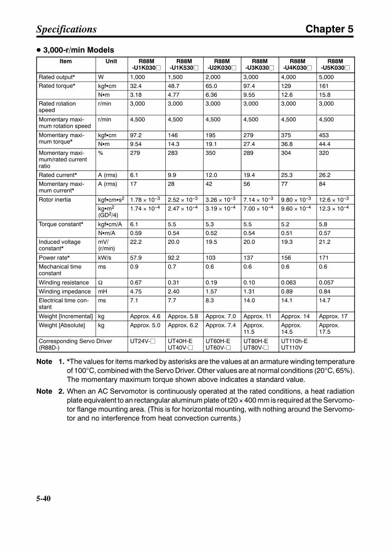
5-40
5-40
D 3,000-r/min ModelsItem Unit R88M
-U1K030jR88M
-U1K530jR88M
-U2K030jR88M
-U3K030jR88M
-U4K030jR88M
-U5K030j
Rated output* W 1,000 1,500 2,000 3,000 4,000 5,000Rated torque* kgfScm 32.4 48.7 65.0 97.4 129 161Rated torque*
NSm 3.18 4.77 6.36 9.55 12.6 15.8Rated rotationspeed
r/min 3,000 3,000 3,000 3,000 3,000 3,000
Momentary maxi-mum rotation speed
r/min 4,500 4,500 4,500 4,500 4,500 4,500
Momentary maxi-mum torque*
kgfScm 97.2 146 195 279 375 453Momentary maxi-mum torque* NSm 9.54 14.3 19.1 27.4 36.8 44.4Momentary maxi-mum/rated currentratio
% 279 283 350 289 304 320
Rated current* A (rms) 6.1 9.9 12.0 19.4 25.3 26.2Momentary maxi-mum current*
A (rms) 17 28 42 56 77 84
Rotor inertia kgfScmSs2 1.78 × 10--3 2.52 × 10--3 3.26 × 10--3 7.14 × 10--3 9.80 × 10--3 12.6 × 10--3Rotor inertia
kgSm2
(GD2/4)1.74 × 10--4 2.47 × 10--4 3.19 × 10--4 7.00 × 10--4 9.60 × 10--4 12.3 × 10--4
Torque constant* kgfScm/A 6.1 5.5 5.3 5.5 5.2 5.8Torque constant*
NSm/A 0.59 0.54 0.52 0.54 0.51 0.57Induced voltageconstant*
mV/(r/min)
22.2 20.0 19.5 20.0 19.3 21.2
Power rate* kW/s 57.9 92.2 103 137 156 171
Mechanical timeconstant
ms 0.9 0.7 0.6 0.6 0.6 0.6
Winding resistance Ω 0.67 0.31 0.19 0.10 0.063 0.057
Winding impedance mH 4.75 2.40 1.57 1.31 0.89 0.84
Electrical time con-stant
ms 7.1 7.7 8.3 14.0 14.1 14.7
Weight [Incremental] kg Approx. 4.6 Approx. 5.8 Approx. 7.0 Approx. 11 Approx. 14 Approx. 17
Weight [Absolute] kg Approx. 5.0 Approx. 6.2 Approx. 7.4 Approx.11.5
Approx.14.5
Approx.17.5
Corresponding Servo Driver(R88D-)
UT24V-j UT40H-EUT40V-j
UT60H-EUT60V-j
UT80H-EUT80V-j
UT110h-EUT110V
Note 1. *The values for items marked by asterisks are the values at an armature winding temperatureof 100°C, combined with the Servo Driver. Other values are at normal conditions (20°C, 65%).The momentary maximum torque shown above indicates a standard value.
Note 2. When an AC Servomotor is continuously operated at the rated conditions, a heat radiationplate equivalent to an rectangular aluminum plate of t20 × 400 mm is required at the Servomo-tor flange mounting area. (This is for horizontal mounting, with nothing around the Servomo-tor and no interference from heat convection currents.)
Specifications Chapter 5

5-41
Caution Do not use 2-kW, 4-kW, or 5-kW servomotors within the shaded portions of the following dia-grams. If the servomotor is used in these regions, the motor may heat, causing the encoder tomalfunction.
RM88M-U2K030j-j (2 kW) RM88M-U4K030j-j (4 kW) RM88M-U5K030j-j (5 kW)
Effectivetorque(N S m)
Effectivetorque(N S m)
Effectivetorque(N S m)
Ambient temperature (_C) Ambient temperature (_C) Ambient temperature (_C)
Specifications Chapter 5

5-42
5-42
H Specifications for Servomotors with Magnetic Brakes
The magnetic brakes installed in Servomotors with brakes are status-holding brakeswith non-magnetized operation. The magnetic brake is released when a magnetic cur-rent (24 VDC) is applied. The magnetic brake is not meant to be used for braking. Using itfor braking will damage it. During Servomotor operation, be sure to release the magneticbrake by applying a magnetic voltage. The specifications for Servomotors with brakesare similar to those for Servomotors without brakes, so except for inertia and weight, thevarious constants are all the same.Note: The inertia for magnetic brakes is the load inertia.
D Specifications for AC Servomotors With Brakes• 1,500-r/min Models
Item Unit R88M-U1K315j-B
R88M-U1K815j-B
R88M-U2K915j-B
R88M-U4K415j-B
R88M-U5K515j-B
Rotor inertia kgfScmSs2 2.09 × 10--2 3.23 × 10--2 4.69 × 10--2 6.89 × 10--2 9.08 × 10--2Rotor inertia
kgSm2
(GD2/4)2.05 × 10--3 3.17 × 10--3 4.60 × 10--3 6.75 × 10--3 8.90 × 10--3
Brake inertia kgfScmSs2 2.1 × 10--3 8.7 × 10--3 8.7 × 10--3Brake inertia
kgSm2
(GD2/4)2.1 × 10--4 8.5 × 10--4 8.5 × 10--4
Total inertia kgfScmSs2 2.30 × 10--2 4.10 × 10--2 5.56 × 10--2 7.76 × 10--2 9.95 × 10--2Total inertia
kgSm2
(GD2/4)2.26 × 10--3 4.02 × 10--3 5.45 × 10--3 7.60 × 10--3 9.75 × 10--3
Weight [Incremental] kg Approx. 12 Approx. 19 Approx. 23.5 Approx. 28.5 Approx. 35
Weight [Absolute]
kg
Approx. 12 Approx. 19.5 Approx. 23.5 Approx. 29 Approx. 36
Excitation voltage V 24 VDC ±10% (No polarity)
Power consumption W (at 20°C) 9.8 18.5 23.5
Current consumption A (at 20°C) 0.41 0.77 0.98
Static friction torque kgfScm 130 440 740Static friction torque
NSm 12.7 43.1 72.6
Absorption time (see note 1) ms (180 max.)
Release time (see note 1) ms (100 max.)
Backlash --- (±0.5°)
Rating --- Continuous
Insulation grade --- Type F (brake only)
Note 1. The operation time measurement is the measured value with a surge killer (CR50500, byOkaya Electric Industrial Co.) installed.
Note 2. The items in parentheses are reference values.
Specifications Chapter 5
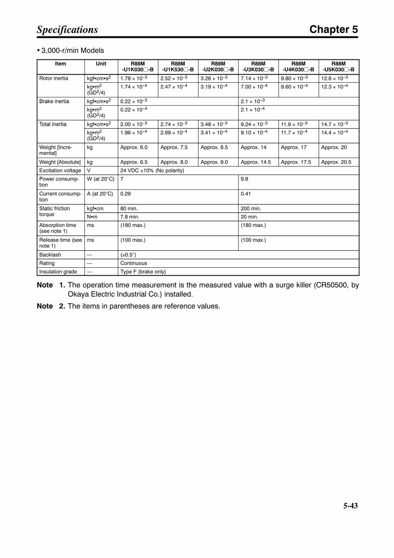
5-43
• 3,000-r/min Models
Item Unit R88M-U1K030j-B
R88M-U1K530j-B
R88M-U2K030j-B
R88M-U3K030j-B
R88M-U4K030j-B
R88M-U5K030j-B
Rotor inertia kgfScmSs2 1.78 × 10--3 2.52 × 10--3 3.26 × 10--3 7.14 × 10--3 9.80 × 10--3 12.6 × 10--3Rotor inertia
kgSm2
(GD2/4)1.74 × 10--4 2.47 × 10--4 3.19 × 10--4 7.00 × 10--4 9.60 × 10--4 12.3 × 10--4
Brake inertia kgfScmSs2 0.22 × 10--3 2.1 × 10--3Brake inertia
kgSm2
(GD2/4)0.22 × 10--4 2.1 × 10--4
Total inertia kgfScmSs2 2.00 × 10--3 2.74 × 10--3 3.48 × 10--3 9.24 × 10--3 11.9 × 10--3 14.7 × 10--3Total inertia
kgSm2
(GD2/4)1.96 × 10--4 2.69 × 10--4 3.41 × 10--4 9.10 × 10--4 11.7 × 10--4 14.4 × 10--4
Weight [Incre-mental]
kg Approx. 6.0 Approx. 7.5 Approx. 8.5 Approx. 14 Approx. 17 Approx. 20
Weight [Absolute] kg Approx. 6.5 Approx. 8.0 Approx. 9.0 Approx. 14.5 Approx. 17.5 Approx. 20.5
Excitation voltage V 24 VDC ±10% (No polarity)
Power consump-tion
W (at 20°C) 7 9.8
Current consump-tion
A (at 20°C) 0.29 0.41
Static frictiontorque
kgfScm 80 min. 200 min.Static frictiontorque NSm 7.8 min. 20 min.
Absorption time(see note 1)
ms (180 max.) (180 max.)
Release time (seenote 1)
ms (100 max.) (100 max.)
Backlash --- (±0.5°)
Rating --- Continuous
Insulation grade --- Type F (brake only)
Note 1. The operation time measurement is the measured value with a surge killer (CR50500, byOkaya Electric Industrial Co.) installed.
Note 2. The items in parentheses are reference values.
Specifications Chapter 5
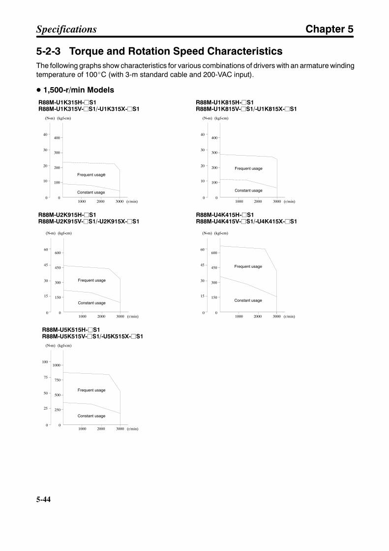
5-44
5-44
5-2-3 Torque and Rotation Speed CharacteristicsThe following graphs show characteristics for various combinations of drivers with an armature windingtemperature of 100_C (with 3-m standard cable and 200-VAC input).
D 1,500-r/min ModelsR88M-U1K315H-jS1R88M-U1K315V-jS1/-U1K315X-jS1
R88M-U1K815H-jS1R88M-U1K815V-jS1/-U1K815X-jS1
Frequent usage
Constant usage
Frequent usage
Constant usage
(kgfScm)(NSm)
(r/min)1000 2000 30000
10
20
30
40
100
200
300
400
0
(kgfScm)(NSm)
(r/min)1000 2000 30000
10
20
30
40
100
200
300
400
0
R88M-U2K915H-jS1R88M-U2K915V-jS1/-U2K915X-jS1
R88M-U4K415H-jS1R88M-U4K415V-jS1/-U4K415X-jS1
Frequent usage
Constant usage
Frequent usage
Constant usage
(kgfScm)(NSm)
(r/min)1000 2000 30000
15
30
45
60
150
300
450
600
0
(kgfScm)(NSm)
(r/min)1000 2000 30000
15
30
45
60
150
300
450
600
0
R88M-U5K515H-jS1R88M-U5K515V-jS1/-U5K515X-jS1
Frequent usage
Constant usage
(kgfScm)(NSm)
(r/min)1000 2000 30000
25
50
75
100
250
500
750
1000
0
Specifications Chapter 5
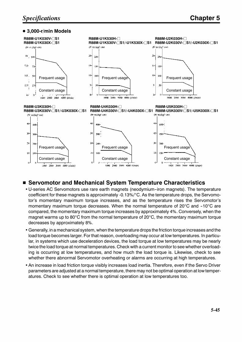
5-45
D 3,000-r/min ModelsR88M-U1K030V-jS1R88M-U1K030X-jS1
R88M-U1K530H-jR88M-U1K530V-jS1/-U1K530X-jS1
R88M-U2K030H-jR88M-U2K030V-jS1/-U2K030X-jS1
Frequent usage
Constant usage
Frequent usage
Constant usage
Frequent usage
Constant usage
R88M-U3K030H-jR88M-U3K030V-jS1/-U3K030X-jS1
R88M-U4K030H-jR88M-U4K030V-jS1/-U4K030X-jS1
R88M-U5K030H-jR88M-U5K030V-jS1/-U5K030X-jS1
Frequent usage
Constant usage
Frequent usage
Constant usage
Frequent usage
Constant usage
H Servomotor and Mechanical System Temperature Characteristics• U-series AC Servomotors use rare earth magnets (neodymium--iron magnets). The temperature
coefficient for these magnets is approximately -0.13%/°C. As the temperature drops, the Servomo-tor’s momentary maximum torque increases, and as the temperature rises the Servomotor’smomentary maximum torque decreases. When the normal temperature of 20°C and --10°C arecompared, the momentary maximum torque increases by approximately 4%. Conversely, when themagnet warms up to 80°C from the normal temperature of 20°C, the momentary maximum torquedecreases by approximately 8%.
• Generally, in a mechanical system, when the temperature drops the friction torque increases and theload torque becomes larger. For that reason, overloading may occur at low temperatures. In particu-lar, in systems which use deceleration devices, the load torque at low temperatures may be nearlytwice the load torque at normal temperatures. Check with a current monitor to see whether overload-ing is occurring at low temperatures, and how much the load torque is. Likewise, check to seewhether there abnormal Servomotor overheating or alarms are occurring at high temperatures.
• An increase in load friction torque visibly increases load inertia. Therefore, even if the Servo Driverparameters are adjusted at a normal temperature, there may not be optimal operation at low temper-atures. Check to see whether there is optimal operation at low temperatures too.
Specifications Chapter 5
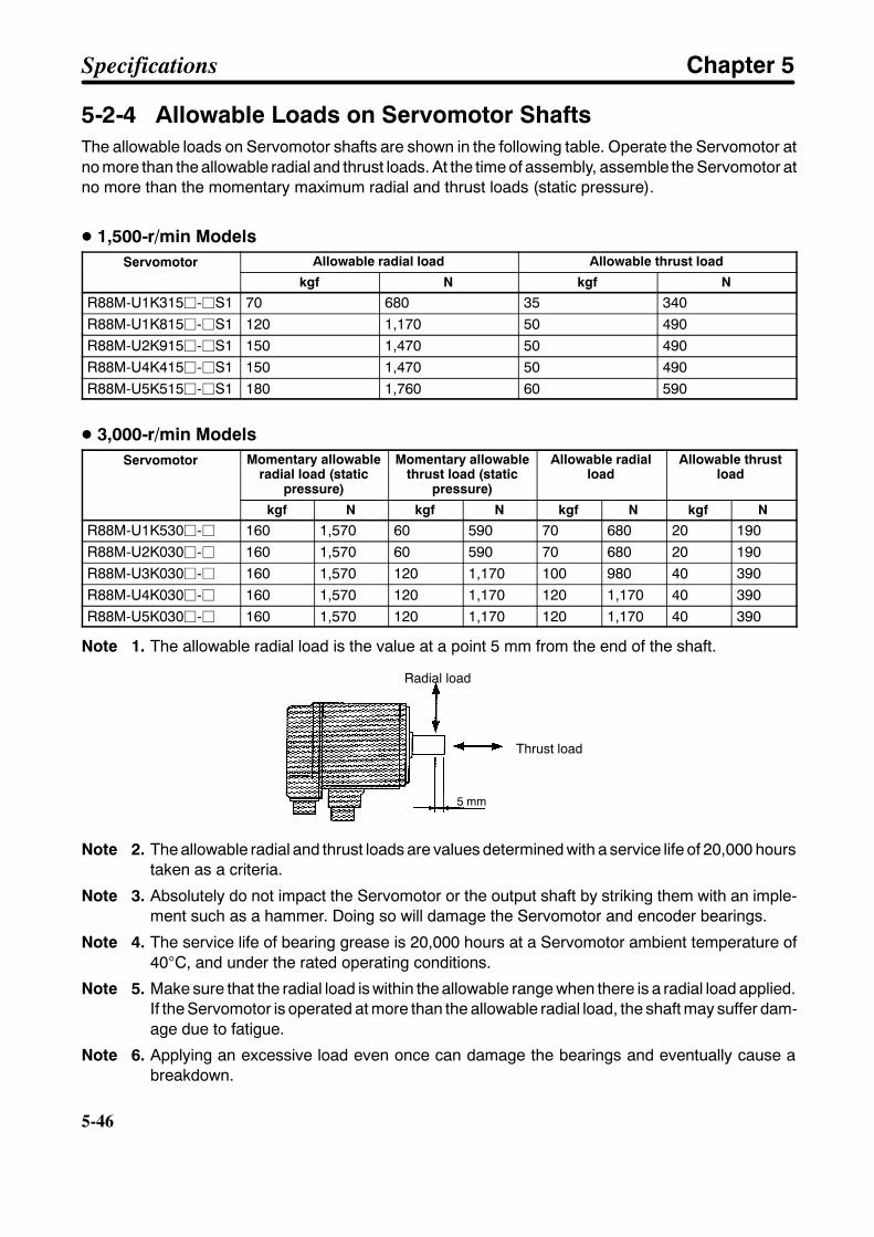
5-46
5-46
5-2-4 Allowable Loads on Servomotor ShaftsThe allowable loads on Servomotor shafts are shown in the following table. Operate the Servomotor atno more than the allowable radial and thrust loads. At the time of assembly, assemble the Servomotor atno more than the momentary maximum radial and thrust loads (static pressure).
D 1,500-r/min ModelsServomotor Allowable radial load Allowable thrust loadServomotor
kgf N kgf N
R88M-U1K315j-jS1 70 680 35 340R88M-U1K815j-jS1 120 1,170 50 490R88M-U2K915j-jS1 150 1,470 50 490R88M-U4K415j-jS1 150 1,470 50 490R88M-U5K515j-jS1 180 1,760 60 590
D 3,000-r/min ModelsServomotor Momentary allowable
radial load (staticpressure)
Momentary allowablethrust load (static
pressure)
Allowable radialload
Allowable thrustload
kgf N kgf N kgf N kgf N
R88M-U1K530j-j 160 1,570 60 590 70 680 20 190R88M-U2K030j-j 160 1,570 60 590 70 680 20 190R88M-U3K030j-j 160 1,570 120 1,170 100 980 40 390R88M-U4K030j-j 160 1,570 120 1,170 120 1,170 40 390R88M-U5K030j-j 160 1,570 120 1,170 120 1,170 40 390
Note 1. The allowable radial load is the value at a point 5 mm from the end of the shaft.
Radial load
Thrust load
5 mm
Note 2. The allowable radial and thrust loads are values determined with a service life of 20,000 hourstaken as a criteria.
Note 3. Absolutely do not impact the Servomotor or the output shaft by striking them with an imple-ment such as a hammer. Doing so will damage the Servomotor and encoder bearings.
Note 4. The service life of bearing grease is 20,000 hours at a Servomotor ambient temperature of40°C, and under the rated operating conditions.
Note 5. Make sure that the radial load is within the allowable range when there is a radial load applied.If the Servomotor is operated at more than the allowable radial load, the shaft may suffer dam-age due to fatigue.
Note 6. Applying an excessive load even once can damage the bearings and eventually cause abreakdown.
Specifications Chapter 5
5-47
5-2-5 Encoder SpecificationsItem 1,500-r/min, 3,000-r/min
[Absolute] models3,000-r/min [Incremental] models
Encoder method Optical encoderNumber of output pulses A, B phase: 8,192 pulses/revolution
Z phase: 1 pulse/revolutionA, B phase: 4,096 pulses/revolutionZ phase: 1 pulse/revolution
Power supply voltage 5 VDC±5%Power supply current DC, 350 mA (for load resistance of
220 Ω)DC, 350 mA (for load resistance of220 Ω)
Phase characteristics 90° ±36°
Phase relationship For rotation in the CW direction, A phase is advanced by 90° compared toB phase.
Maximum rotation speed 3,000 r/min 4,500 r/minMaximum response frequency 409.6 kHz 307.2 kHzOutput signals +A, --A, +B, --B, +S, --S +A, --A, +B, --B, +S, --SOutput impedance Conforming to EIA RS-422A.
Output based on MC3487 or equivalent.Serial communications data Z phase, poll sensor, U, V, W phaseSerial communications method Combination communications method based on A, B, and S phases.
Specifications Chapter 5

5-48
5-48
5-3 Cable Specifications
5-3-1 Controller Connecting Cable
H Connecting Cables for CV500-MC221/421/C200H-MC221
D Types of CableNumber of axes Model Length (L) Outer diameter of sheath
1 R88A-CPUB001M1 1 m 8.3 dia.1R88A-CPUB002M1 2 m
8.3 dia.
2 R88A-CPUB001M2 1 m 8.3 dia.2R88A-CPUB002M2 2 m
8.3 dia.
D Connection Configuration (For 1 Axis)
CV500-MC221/421C200H-MC221
OMNUC U-seriesAC Servo Driver(R88D-UTj)
43.5
39.0 39.0
t=18 t=18
52.4
Specifications Chapter 5

5-49
D Wiring (For 1 Axis)
OMNUC U-seriesAC Servo DriverCV500-MC221/MC421
Signal Insulation color/Marking color/MarkingAWG20 BlackAWG20 Red
*AWG20 Blue*AWG20 Red
Signal
Connector plug:10150-3000VE (Sumitomo 3M)
Connector case:10350-52A0-008 (Sumitomo 3M)
Connector plug:10136-3000VE (Sumitomo 3M)
Connector case:10336-52A0-008 (Sumitomo 3M)
White/Black --
Pink/Black --Yellow/Black --
Gray/Black --Gray/Red --
Orange/Black -- --
White/Red --
White/Black --Yellow/Red --
Yellow/Black --
Pink/Red --Pink/Black --Orange/Red --
Orange/Black --
Orange/Black --Gray/Black --
*
*
*
*
21
22
31
40
44
2
4
1
33
34
36
35
19
20
5
6
Shell
47
32
Note 1. The Controller’s symbols are the DRVX-Y connector’s symbols. In a DRVZ-U connector, X →Z and Y → U.
Note 2. The terminals and wires marked with asterisks are used with Absolute Encoders.
Note 3. Supply 24 VDC to the two wires (black and red) that are taken out from the Controller’s con-nector. (Red is + and black is --.)
Specifications Chapter 5
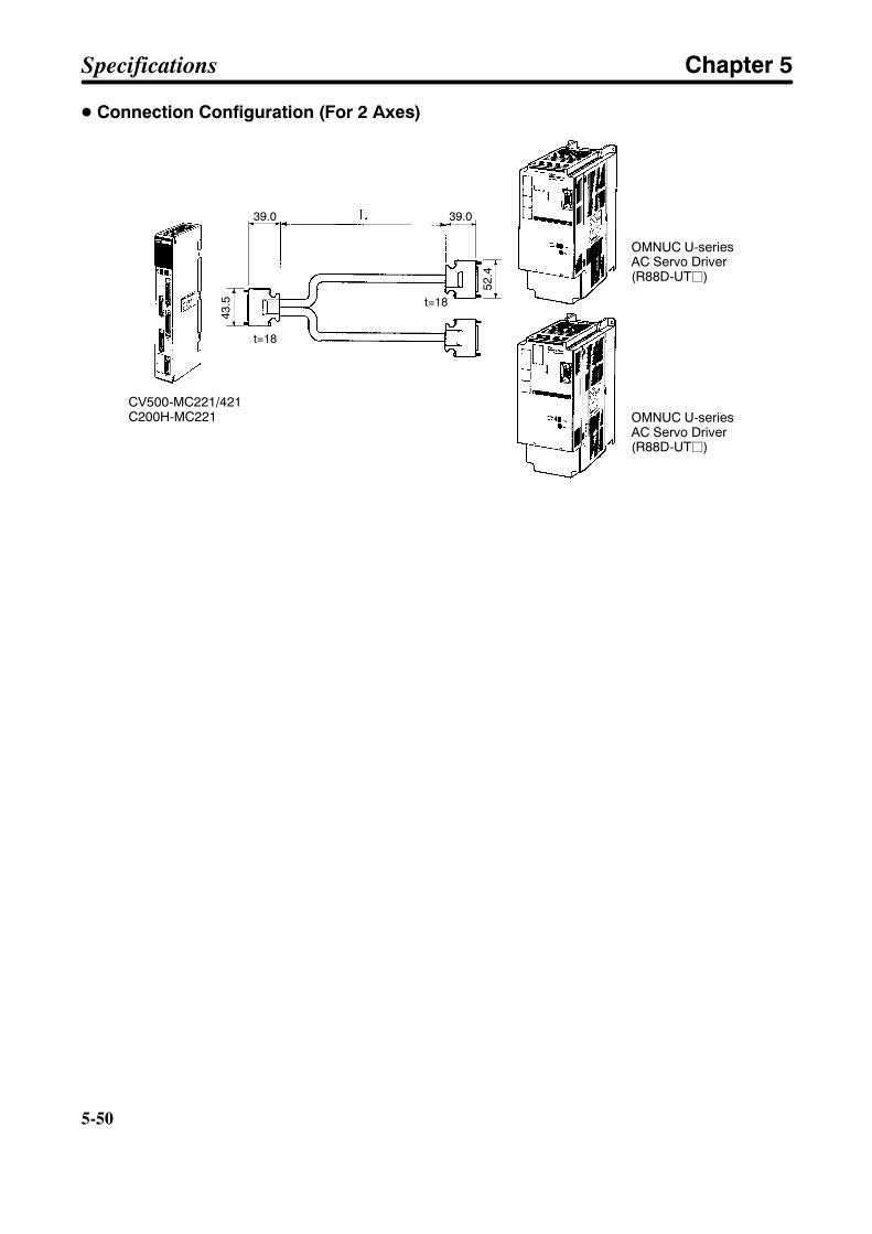
5-50
5-50
D Connection Configuration (For 2 Axes)
CV500-MC221/421C200H-MC221
OMNUC U-seriesAC Servo Driver(R88D-UTj)
OMNUC U-seriesAC Servo Driver(R88D-UTj)
43.5
52.4
39.0 39.0
t=18
t=18
Specifications Chapter 5
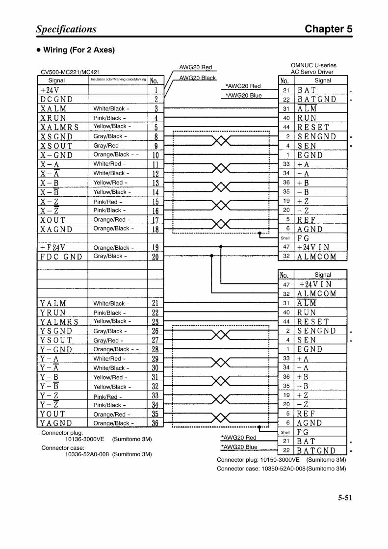
5-51
D Wiring (For 2 Axes)
CV500-MC221/MC421Signal Insulation color/Marking color/Marking
White/Black --
Pink/Black --Yellow/Black --
Gray/Black --
Gray/Red --Orange/Black -- --
White/Red --
White/Black --
Yellow/Red --
Yellow/Black --
Pink/Red --Pink/Black --
Orange/Red --Orange/Black --
Orange/Black --Gray/Black --
White/Black --
Pink/Black --Yellow/Black --
Gray/Black --
Gray/Red --Orange/Black -- --
White/Red --
White/Black --
Yellow/Red --
Yellow/Black --
Pink/Red --Pink/Black --
Orange/Red --Orange/Black --
Connector plug:10136-3000VE (Sumitomo 3M)
Connector case:10336-52A0-008 (Sumitomo 3M)
*AWG20 Blue
*AWG20 Red
AWG20 Black
AWG20 Red
*AWG20 Blue
*AWG20 Red
OMNUC U-seriesAC Servo Driver
Signal
Signal
Connector plug: 10150-3000VE (Sumitomo 3M)Connector case: 10350-52A0-008(Sumitomo 3M)
**
**
**
**
21
22
31
40
44
2
4
1
33
34
36
35
19
20
5
6
Shell
47
32
47
32
31
40
44
2
4
1
33
34
36
35
19
20
5
6
Shell
21
22
Specifications Chapter 5
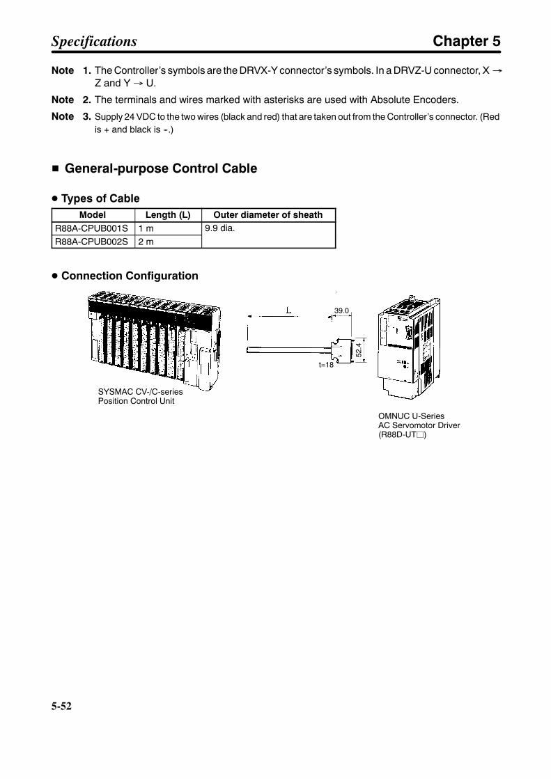
5-52
5-52
Note 1. The Controller’s symbols are the DRVX-Y connector’s symbols. In a DRVZ-U connector, X →Z and Y → U.
Note 2. The terminals and wires marked with asterisks are used with Absolute Encoders.
Note 3. Supply 24 VDC to the two wires (black and red) that are taken out from the Controller’s connector. (Redis + and black is --.)
H General-purpose Control Cable
D Types of CableModel Length (L) Outer diameter of sheath
R88A-CPUB001S 1 m 9.9 dia.R88A-CPUB002S 2 m
9.9 dia.
D Connection Configuration
SYSMAC CV-/C-seriesPosition Control Unit
OMNUC U-SeriesAC Servomotor Driver(R88D-UTj)
52.4
39.0
t=18
Specifications Chapter 5
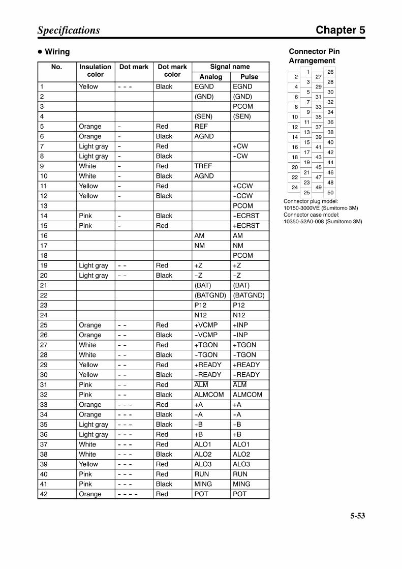
5-53
D Wiring
No. Insulationcolor
Dot mark Dot markcolor
Signal nameNo. Insulationcolor
Dot mark Dot markcolor Analog Pulse
1 Yellow -- -- -- Black EGND EGND2 (GND) (GND)3 PCOM4 (SEN) (SEN)5 Orange -- Red REF6 Orange -- Black AGND7 Light gray -- Red +CW8 Light gray -- Black --CW9 White -- Red TREF10 White -- Black AGND11 Yellow -- Red +CCW12 Yellow -- Black --CCW13 PCOM14 Pink -- Black --ECRST15 Pink -- Red +ECRST16 AM AM17 NM NM18 PCOM19 Light gray -- -- Red +Z +Z20 Light gray -- -- Black --Z --Z21 (BAT) (BAT)22 (BATGND) (BATGND)23 P12 P1224 N12 N1225 Orange -- -- Red +VCMP +INP26 Orange -- -- Black --VCMP --INP27 White -- -- Red +TGON +TGON28 White -- -- Black --TGON --TGON29 Yellow -- -- Red +READY +READY30 Yellow -- -- Black --READY --READY31 Pink -- -- Red ALM ALM32 Pink -- -- Black ALMCOM ALMCOM33 Orange -- -- -- Red +A +A34 Orange -- -- -- Black --A --A35 Light gray -- -- -- Black --B --B36 Light gray -- -- -- Red +B +B37 White -- -- -- Red ALO1 ALO138 White -- -- -- Black ALO2 ALO239 Yellow -- -- -- Red ALO3 ALO340 Pink -- -- -- Red RUN RUN41 Pink -- -- -- Black MING MING42 Orange -- -- -- -- Red POT POT
Specifications Chapter 5
Connector PinArrangement
Connector plug model:10150-3000VE (Sumitomo 3M)Connector case model:10350-52A0-008 (Sumitomo 3M)
2
4
6
8
10
12
14
16
18
1
3
5
7
9
11
13
15
17
27
29
31
33
35
37
39
41
43
26
28
30
32
34
36
38
40
42
20
22
24
19
21
23
25
45
47
49
44
46
48
50

5-54
5-54
No. Signal nameDot markcolor
Dot markInsulationcolor
No.PulseAnalog
Dot markcolor
Dot markInsulationcolor
43 Orange -- -- -- -- Black NOT NOT44 Light gray -- -- -- -- Black RESET RESET45 White -- -- -- -- Red PCL PCL46 White -- -- -- -- Black NCL NCL47 Light gray -- -- -- -- Red +24VIN +24VIN484950 Shield FG FG
Cable: AWG24X18P
Specifications Chapter 5
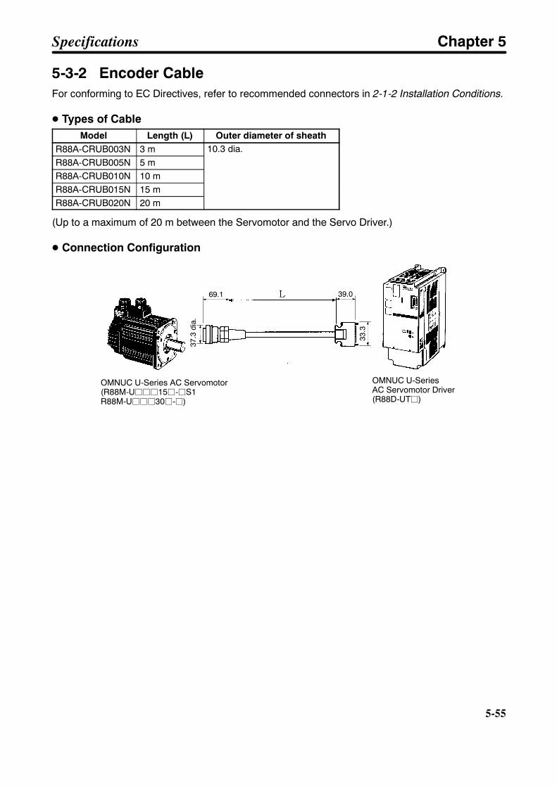
5-55
5-3-2 Encoder CableFor conforming to EC Directives, refer to recommended connectors in 2-1-2 Installation Conditions.
D Types of CableModel Length (L) Outer diameter of sheath
R88A-CRUB003N 3 m 10.3 dia.R88A-CRUB005N 5 m
10.3 dia.
R88A-CRUB010N 10 mR88A-CRUB015N 15 mR88A-CRUB020N 20 m
(Up to a maximum of 20 m between the Servomotor and the Servo Driver.)
D Connection Configuration
OMNUC U-Series AC Servomotor(R88M-Ujjj15j-jS1R88M-Ujjj30j-j)
OMNUC U-SeriesAC Servomotor Driver(R88D-UTj)
37.3
dia.
69.1
33.3
39.0
Specifications Chapter 5
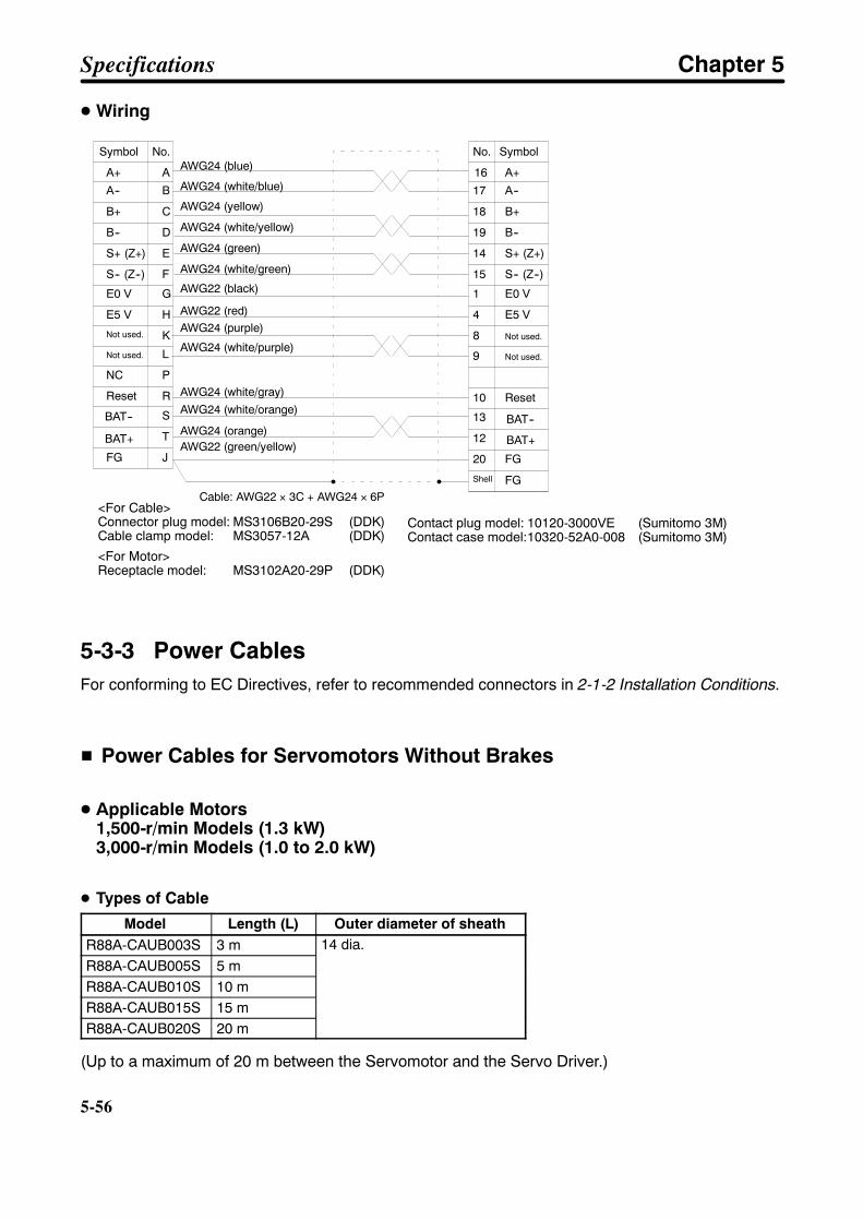
5-56
5-56
D Wiring
A+ A
A-- B
B+ C
B-- D
S+ (Z+) E
S-- (Z--) F
E0 V G
E5 V H
Not used. K
16
17
18
19
14
15
1
4
8
A+
A--
B+
B--
S+ (Z+)
S-- (Z--)
E0 V
E5 V
Not used.
AWG24 (blue)
AWG24 (white/blue)
AWG24 (yellow)
AWG24 (white/yellow)
AWG24 (green)
AWG24 (white/green)
AWG22 (black)
AWG22 (red)
AWG22 (green/yellow)
Symbol No. SymbolNo.
Cable: AWG22 × 3C + AWG24 × 6P
Not used. L
NC P
Reset R
BAT-- S
BAT+ T
FG J
9
10
13
12
20
Not used.
Reset
FG
AWG24 (purple)
AWG24 (white/purple)
AWG24 (white/gray)AWG24 (white/orange)
AWG24 (orange)
Shell FG
BAT--
BAT+
Contact plug model: 10120-3000VE (Sumitomo 3M)Contact case model:10320-52A0-008 (Sumitomo 3M)
<For Cable>Connector plug model: MS3106B20-29S (DDK)Cable clamp model: MS3057-12A (DDK)
<For Motor>Receptacle model: MS3102A20-29P (DDK)
5-3-3 Power CablesFor conforming to EC Directives, refer to recommended connectors in 2-1-2 Installation Conditions.
H Power Cables for Servomotors Without Brakes
D Applicable Motors1,500-r/min Models (1.3 kW)3,000-r/min Models (1.0 to 2.0 kW)
D Types of Cable
Model Length (L) Outer diameter of sheathR88A-CAUB003S 3 m 14 dia.R88A-CAUB005S 5 m
14 dia.
R88A-CAUB010S 10 mR88A-CAUB015S 15 mR88A-CAUB020S 20 m
(Up to a maximum of 20 m between the Servomotor and the Servo Driver.)
Specifications Chapter 5
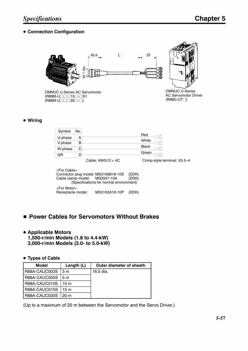
5-57
D Connection Configuration
OMNUC U-Series AC Servomotor(R88M-Ujjj15j-jS1(R88M-Ujjj30j-j)
OMNUC U-SeriesAC Servomotor Driver(R88D-UTj)
34.1
dia.
65.9
D Wiring
U-phase AV-phase B
W-phase C
GR D
RedWhite
Black
Green
Symbol No.
Cable: AWG12 × 4C Crimp-style terminal: V5.5--4
<For Cable>Connector plug model: MS3106B18-10S (DDK)Cable clamp model: MS3057-10A (DDK)
(Specifications for normal environment)
<For Motor>Receptacle model: MS3102A18-10P (DDK)
H Power Cables for Servomotors Without Brakes
D Applicable Motors1,500-r/min Models (1.8 to 4.4-kW)3,000-r/min Models (3.0- to 5.0-kW)
D Types of Cable
Model Length (L) Outer diameter of sheathR88A-CAUC003S 3 m 16.5 dia.R88A-CAUC005S 5 m
16.5 dia.
R88A-CAUC010S 10 mR88A-CAUC015S 15 mR88A-CAUC020S 20 m
(Up to a maximum of 20 m between the Servomotor and the Servo Driver.)
Specifications Chapter 5
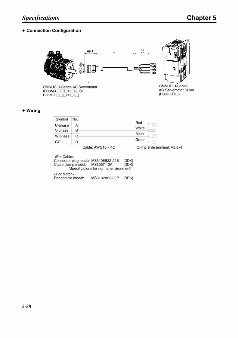
5-58
5-58
D Connection Configuration
OMNUC U-Series AC Servomotor(R88M-Ujjj15j-jS1R88M-Ujjj30j-j)
OMNUC U-SeriesAC Servomotor Driver(R88D-UTj)
40.5
dia.
69.1
D Wiring
U-phase AV-phase B
W-phase C
GR D
RedWhite
Black
Green
Symbol No.
Cable: AWG10 × 4C Crimp-style terminal: V5.5--4
<For Cable>Connector plug model: MS3106B22-22S (DDK)Cable clamp model: MS3057-12A (DDK)
(Specifications for normal environment)
<For Motor>Receptacle model: MS3102A22-22P (DDK)
Specifications Chapter 5
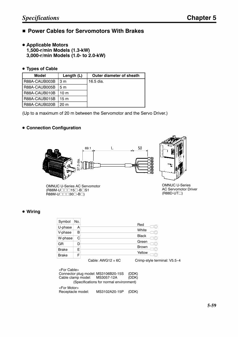
5-59
H Power Cables for Servomotors With Brakes
D Applicable Motors1,500-r/min Models (1.3-kW)3,000-r/min Models (1.0- to 2.0-kW)
D Types of Cable
Model Length (L) Outer diameter of sheathR88A-CAUB003B 3 m 16.5 dia.R88A-CAUB005B 5 m
16.5 dia.
R88A-CAUB010B 10 mR88A-CAUB015B 15 mR88A-CAUB020B 20 m
(Up to a maximum of 20 m between the Servomotor and the Servo Driver.)
D Connection Configuration
OMNUC U-Series AC Servomotor(R88M-Ujjj15j-BjS1R88M-Ujjj30j-Bj)
OMNUC U-SeriesAC Servomotor Driver(R88D-UTj)
37.3
dia.
69.1
D Wiring
U-phase AV-phase B
W-phase C
GR D
RedWhite
Black
Green
Brake E
Brake F
Brown
Yellow
Symbol No.
Cable: AWG12 × 6C Crimp-style terminal: V5.5--4
<For Cable>Connector plug model: MS3106B20-15S (DDK)Cable clamp model: MS3057-12A (DDK)
(Specifications for normal environment)
<For Motor>Receptacle model: MS3102A20-15P (DDK)
Specifications Chapter 5
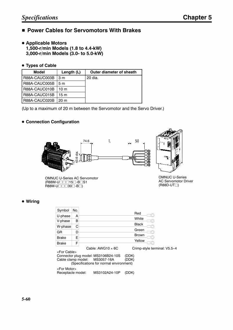
5-60
5-60
H Power Cables for Servomotors With Brakes
D Applicable Motors1,500-r/min Models (1.8 to 4.4-kW)3,000-r/min Models (3.0- to 5.0-kW)
D Types of CableModel Length (L) Outer diameter of sheath
R88A-CAUC003B 3 m 20 dia.R88A-CAUC005B 5 m
20 dia.
R88A-CAUC010B 10 mR88A-CAUC015B 15 mR88A-CAUC020B 20 m
(Up to a maximum of 20 m between the Servomotor and the Servo Driver.)
D Connection Configuration
OMNUC U-Series AC Servomotor(R88M-Ujjj15j-BjS1R88M-Ujjj30j-Bj)
OMNUC U-SeriesAC Servomotor Driver(R88D-UTj)
43.6
dia.
74.6
D Wiring
U-phase AV-phase B
W-phase C
GR D
RedWhite
Black
Green
Brake E
Brake F
Brown
Yellow
Symbol No.
Cable: AWG10 × 6C Crimp-style terminal: V5.5--4<For Cable>Connector plug model: MS3106B24-10S (DDK)Cable clamp model: MS3057-16A (DDK)
(Specifications for normal environment)
<For Motor>Receptacle model: MS3102A24-10P (DDK)
Specifications Chapter 5
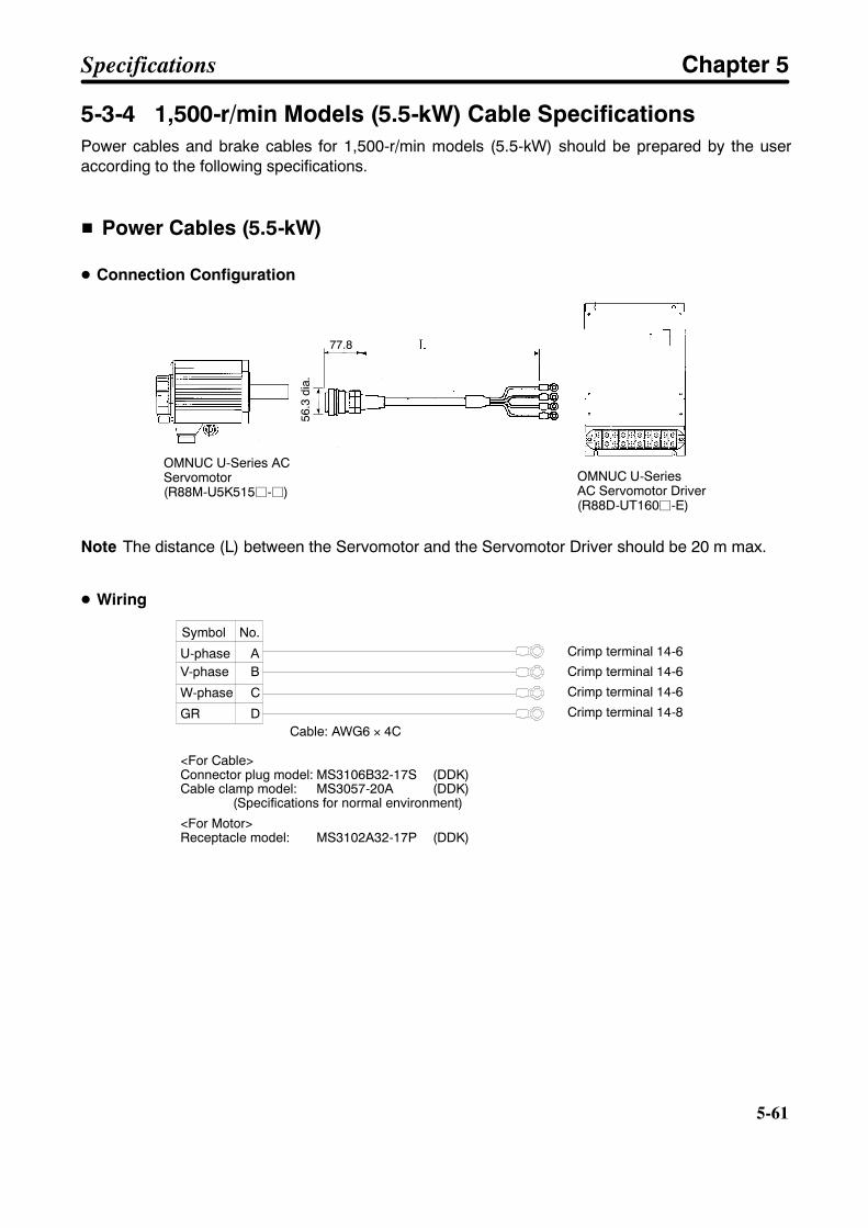
5-61
5-3-4 1,500-r/min Models (5.5-kW) Cable SpecificationsPower cables and brake cables for 1,500-r/min models (5.5-kW) should be prepared by the useraccording to the following specifications.
H Power Cables (5.5-kW)
D Connection Configuration
OMNUC U-Series ACServomotor(R88M-U5K515j-j)
OMNUC U-SeriesAC Servomotor Driver(R88D-UT160j-E)
56.3
dia.
77.8
Note The distance (L) between the Servomotor and the Servomotor Driver should be 20 m max.
D Wiring
U-phase AV-phase B
W-phase C
GR D
Symbol No.
Cable: AWG6 × 4C
Crimp terminal 14-6
Crimp terminal 14-6
Crimp terminal 14-6
Crimp terminal 14-8
<For Cable>Connector plug model: MS3106B32-17S (DDK)Cable clamp model: MS3057-20A (DDK)
(Specifications for normal environment)
<For Motor>Receptacle model: MS3102A32-17P (DDK)
Specifications Chapter 5
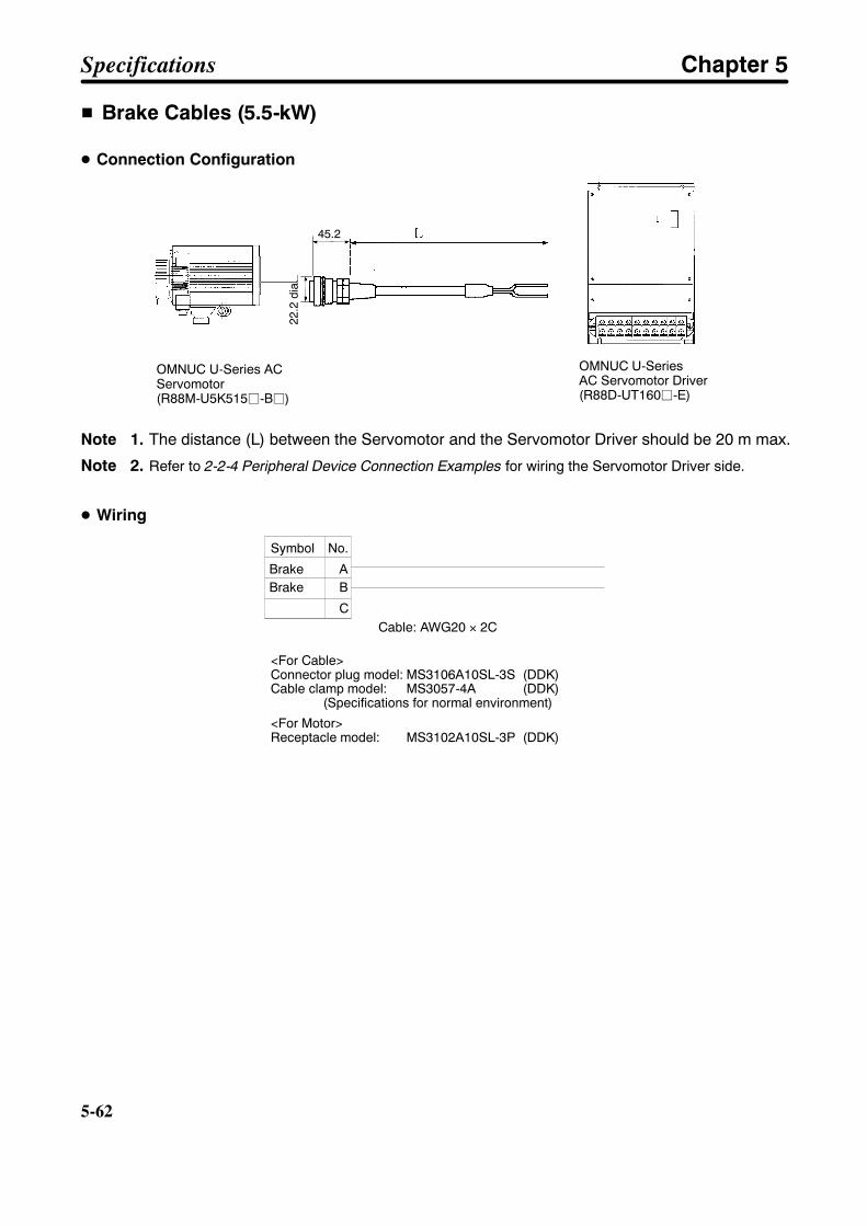
5-62
5-62
H Brake Cables (5.5-kW)
D Connection Configuration
OMNUC U-Series ACServomotor(R88M-U5K515j-Bj)
OMNUC U-SeriesAC Servomotor Driver(R88D-UT160j-E)
22.2
dia.
45.2
Note 1. The distance (L) between the Servomotor and the Servomotor Driver should be 20 m max.
Note 2. Refer to 2-2-4 Peripheral Device Connection Examples for wiring the Servomotor Driver side.
D Wiring
Brake ABrake B
C
Symbol No.
Cable: AWG20 × 2C
<For Cable>Connector plug model: MS3106A10SL-3S (DDK)Cable clamp model: MS3057-4A (DDK)
(Specifications for normal environment)
<For Motor>Receptacle model: MS3102A10SL-3P (DDK)
Specifications Chapter 5

5-63
5-4 Parameter Unit Specifications
H General SpecificationsItem Standards
Operating ambient temperature 0°C to 55°CStorage ambient temperature --10°C to 75°COperating ambient humidity 35% to 85% RH (with no condensation)Storage ambient humidity 35% to 85% RH (with no condensation)Storage and operatingatmosphere
No corrosive gasses.
Vibration resistance 4.9 m/s2 0.5 G max.Impact resistance Acceleration 19.6 m/s2 2 G max.
H Performance SpecificationsModel R88A-PR02U R88A-PR03U
Type Handy type Mounted typeAccessory cable 1,000 mm (Connected by connectors.)Connectors 7910-7500SC (10 pins) D sub-connector (9 pins)Display 7-segment LED, 5 digitsExternal dimensions 63 × 135 × 18.5 (W × H × D) 54 × 57.5 × 15 (W × H × D)Commu-nications
Standard RS-232C RS-422ACommu-nicationsspecifica-tions
Communicationsmethod
Asynchronous (ASYNC)
tionsBaud rate 2,400 bpsStart bits 1 bitData 8 bitsParity NoneStop bits 1 bit
Errors detected by ParameterUnit
Display CPF00 Cannot transmit even after 5 seconds haveelapses since power supply was turned on.Unit
CPF01 A BCC error or faulty reception data has occurredfor five consecutive times, or a time overrun (1 s)has occurred for three consecutive times.
Specifications Chapter 5

Chapter 6
Appendix6-1 Connection Examples
6-2 Encoder Divider Rate for Servo Controllers6-3 OMNUC U-series Models
6-4 Combinations of Servo Drivers and Servomo-tors
6
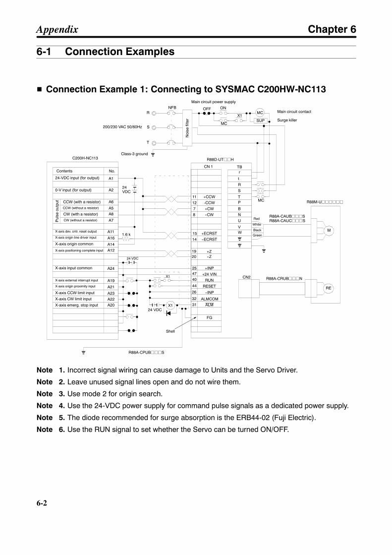
6-2
6-2
6-1 Connection Examples
H Connection Example 1: Connecting to SYSMAC C200HW-NC113
ALM31
CN2
+CCW
t
R
S
TP
B
TB
M
RE
R88D-UTjjH
R88M-Ujjjjjj
R88A-CRUBjjjN
CN 1
-CCW
+CW
--ECRST
+INP
+24 VIN
RUN
RESET
--INP
--CW
+Z--Z
11
7
14
254740
44
26
8
1920
32
12
R88A-CAUBjjjSR88A-CAUCjjjSRed
White
Black
Green
R88A-CPUBjjjS
Class-3 ground
R
T
Noi
sefil
ter
NFB
S
OFF ON
Main circuit power supply
SUP
MC
MC
X1
N
U
VW
MC
r
FG
ALMCOM
+ECRST15
A1
X124 VDC
24 VDC
24VDC
1.6 k
C200H-NC113
200/230 VAC 50/60Hz
X1
Contents
24-VDC input (for output)
0-V input (for output)
CCW (with a resistor)CCW (without a resistor)
CW (with a resistor)CW (without a resistor)P
ulse
outp
ut
X-axis origin line driver input
Main circuit contact
Surge killer
No.
Shell
A2
A6
A5A8
A7
A11X-axis dev. cntr. reset output
X-axis CW limit input
A12X-axis positioning complete input
A16
A14X-axis origin common
X-axis input common
X-axis emerg. stop input
X-axis external interrupt input
A24
X-axis CCW limit input
X-axis origin proximity input
A19
A22
A21
A23
A20
Note 1. Incorrect signal wiring can cause damage to Units and the Servo Driver.
Note 2. Leave unused signal lines open and do not wire them.
Note 3. Use mode 2 for origin search.
Note 4. Use the 24-VDC power supply for command pulse signals as a dedicated power supply.
Note 5. The diode recommended for surge absorption is the ERB44-02 (Fuji Electric).
Note 6. Use the RUN signal to set whether the Servo can be turned ON/OFF.
Appendix Chapter 6

6-3
H Connection Example 2: Connecting to SYSMAC C200H-NC112 PositionControl Units
ALM31
CN2
+CCW
t
R
S
TP
B
TB
M
RE
R88D-UTj
R88M-Ujjjjjj
R88A-CRUBjjjN
CN 1
-CCW
+CW
--ECRST
+INP
+24 VIN
RUN
RESET
--INP
--CW
+Z--Z
11
7
14
254740
44
26
8
1920
32
12
R88A-CAUBjjjSR88A-CAUCjjjSRed
White
Black
Green
R88A-CPUBjjjS
Class-3 ground
R
T
Noi
sefil
ter
NFB
S
OFF ON
Main circuit power supply
SUP
MC
MC
X1
N
U
VW
MC
r
FG
Shell
ALMCOM
+ECRST150 V
1
2
3
4
5
6
8
9
10
12
13
19
20
0 V
A
B
A
B
A
B
A
B
A
B
A
B
A
B
A
B
A
B
A
B
A
B
A
B
A
B
X124 VDC
12 to 24 VDC
24VDC
1.6 k
C200H-NC112
200/230 VAC 50/60Hz
X1
Contents
24-VDC input (for output)
5-VDC input (for output)CCW (with a resistor)CCW (without a resistor)
CW (with a resistor)CW (without a resistor)P
ulse
outp
ut
Dev. counter reset output
Origin line driver input
Positioning completioninput
Origin proximity input
CCW limit input
CW limit input
External interrupt input
Emergency stop input
Main circuit contact
Surge killer
No.
Note 1. Incorrect signal wiring can cause damage to Units and the Servo Driver.
Note 2. Leave unused signal lines open and do not wire them.
Note 3. Use mode 2 for origin search.
Note 4. Use the 24-VDC power supply for command pulse signals as a dedicated power supply.
Note 5. The diode recommended for surge absorption is the ERB44-02 (Fuji Electric).
Note 6. Use the RUN signal to set whether the Servo can be turned ON/OFF.
Appendix Chapter 6
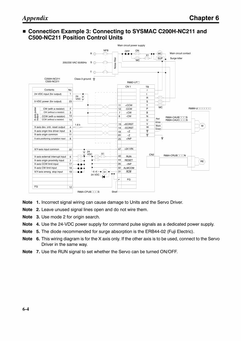
6-4
6-4
H Connection Example 3: Connecting to SYSMAC C200H-NC211 andC500-NC211 Position Control Units
ALM31
CN2
+CCW
t
R
S
TP
B
TB
M
RE
R88D-UTj
R88M-Ujjjjjj
R88A-CRUBjjjN
CN 1
-CCW
+CW
--ECRST
+INP
+24 VIN
RUN
RESET
--INP
--CW
+Z
--Z
11
7
14
25
47
40
44
26
8
1920
32
12
R88A-CAUBjjjSR88A-CAUCjjjSRed
White
Black
Green
R88A-CPUBjjjS
Class-3 ground
R
T
Noi
sefil
ter
NFB
S
OFF ON
Main circuit power supply
SUP
MC
MC
X1
N
U
VW
MC
r
FG
Shell
ALMCOM
+ECRST15
X124 VDC
24VDC
1.6 k
C200H-NC211C500-NC211
200/230 VAC 50/60Hz
1
23
2
313
14
4
911
8
22
6
717
18
19
12FG
X1
No.Contents
CW (with a resistor)CW (without a resistor)
CCW (with a resistor)CCW (without a resistor)
0-VDC power (for output)
X-a
xis
puls
eou
tput
X-axis dev. cntr. reset output
X-axis origin line driver inputX-axis origin common
X-axis positioning completion input
X/Y-axis input common
X-axis external interrupt input
X-axis origin proximity input
24-VDC input (for output)
X-axis CCW limit input
X-axis CW limit input
X/Y-axis emerg. stop input
Main circuit contact
Surge killer
24VDC
Note 1. Incorrect signal wiring can cause damage to Units and the Servo Driver.
Note 2. Leave unused signal lines open and do not wire them.
Note 3. Use mode 2 for origin search.
Note 4. Use the 24-VDC power supply for command pulse signals as a dedicated power supply.
Note 5. The diode recommended for surge absorption is the ERB44-02 (Fuji Electric).
Note 6. This wiring diagram is for the X axis only. If the other axis is to be used, connect to the ServoDriver in the same way.
Note 7. Use the RUN signal to set whether the Servo can be turned ON/OFF.
Appendix Chapter 6
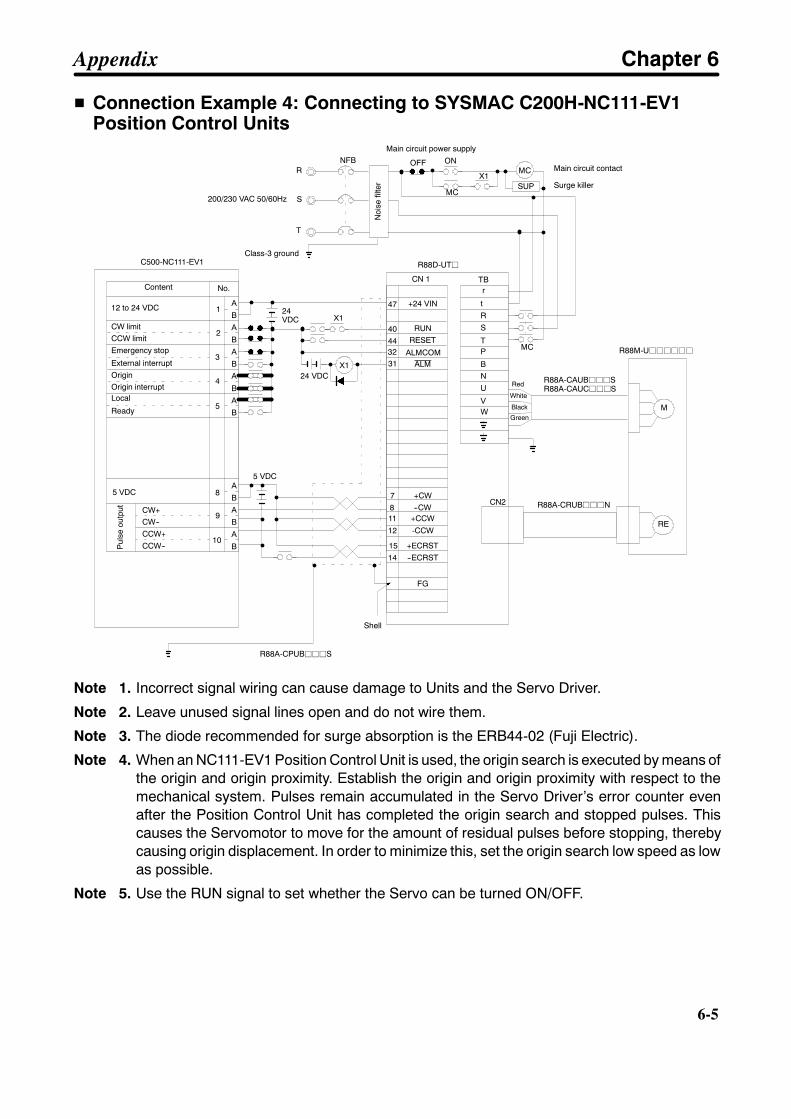
6-5
H Connection Example 4: Connecting to SYSMAC C200H-NC111-EV1Position Control Units
ALM31
CN2
+CCW
t
R
S
TP
B
TB
M
RE
R88D-UTj
R88M-Ujjjjjj
R88A-CRUBjjjN
CN 1
-CCW
+CW
--ECRST
+24 VIN
RUNRESET
--CW11
7
14
47
4044
8
32
12
R88A-CAUBjjjSR88A-CAUCjjjS
Red
White
Black
Green
R88A-CPUBjjjS
Class-3 ground
R
T
Noi
sefil
ter
NFB
S
OFF ON
Main circuit power supply
SUP
MC
MC
X1
N
U
VW
MC
r
FG
Shell
ALMCOM
+ECRST15
1
2
3
4
5
8
9
10
A
B
A
B
A
B
A
B
A
B
A
B
A
B
A
B
X124 VDC
5 VDC
24VDC
C500-NC111-EV1
200/230 VAC 50/60Hz
CW+CW--CCW+CCW--
5 VDC
X1
Content No.
12 to 24 VDC
CW limitCCW limitEmergency stop
External interruptOriginOrigin interruptLocal
Ready
Pul
seou
tput
Main circuit contact
Surge killer
Note 1. Incorrect signal wiring can cause damage to Units and the Servo Driver.
Note 2. Leave unused signal lines open and do not wire them.
Note 3. The diode recommended for surge absorption is the ERB44-02 (Fuji Electric).
Note 4. When an NC111-EV1 Position Control Unit is used, the origin search is executed by means ofthe origin and origin proximity. Establish the origin and origin proximity with respect to themechanical system. Pulses remain accumulated in the Servo Driver’s error counter evenafter the Position Control Unit has completed the origin search and stopped pulses. Thiscauses the Servomotor to move for the amount of residual pulses before stopping, therebycausing origin displacement. In order to minimize this, set the origin search low speed as lowas possible.
Note 5. Use the RUN signal to set whether the Servo can be turned ON/OFF.
Appendix Chapter 6

6-6
6-6
H Connection Example 5: Connecting to SYSMAC C200H-NC222-EPosition Control Units
Signal ALM31
CN2
+A t
R
S
TP
B
TB
M
RE
R88D-UTj
R88M-Ujjjjjj
R88A-CRUBjjjN
CN 1
-A
--B
REF
+24 VINRUN
RESET
+Z
--Z
33
35
5
47
4044
1920
32
34
R88A-CAUBjjjSR88A-CAUCjjjS
Red
White
Black
Green
R88A-CPUBjjjS
Class-3 ground
R
T
Noi
sefil
ter
NFB
S
OFF ON
Main circuit power supply
SUP
MC
MC
X1
N
U
VW
MC
r
FG
Shell
ALMCOM
+B36
X124 VDC
24 VDC
C500-NC222-E
200/230 VAC 50/60Hz
7
5
16
159
8
17
1112
2
12
34
5
6
110 V
X1
No.
6
4
1
X-AX-AX-BX-B
X-Z
X-ZXOUT
XAG
0 VDC GND
+24 V
+24 V
OUT 2X
DC GND
78
9
No.DC GND
+24 V
+24 V
DC GND
CCWL X
STP X
ORG X
SERVO X
CWL X
FG
6 AGND
24 VDC
MD Connector
Name Signal
X axis + A-phase inputX axis -- A-phase inputX axis + B-phase inputX axis -- B-phase inputX axis + Z-phase inputX axis -- Z-phase input
X-axis speed commandX-axis speed cmnd., 0V
24 V for OUT output
X-axis OUT 2 output
EXT IN Connector
Name
X-axis CCW limit inputX-axis extrnl. stop input
X-axis external servo free input
X-axis CW limit input
0 V
X-axis origin input
Frame ground
24 V for input
Main circuit contact
Surge killer
Note 1. Incorrect signal wiring can cause damage to Units and the Servo Driver.
Note 2. Leave unused signal lines open and do not wire them.
Note 3. The diode recommended for surge absorption is the ERB44-02 (Fuji Electric).
Note 4. This wiring diagram is an example of X-axis wiring only. For two-axis control, the externalinput and Driver wiring must be connected for the Y axis in the same way.
Note 5. External output 2 (OUT 2X) can be turned ON and OFF with external servo-free input, atwhich time external output 2 of the C500-NC222-E’s address numbers 420 (X axis) and 820(Y axis) must be set to 1 (turned OFF at the time of servo free).
Note 6. When the C500-NC222-E is used in NC221 mode, external servo-free input works as emer-gency stop input. Therefore external output 2 cannot be used as a RUN signal. Input a RUNsignal from other I/O terminals.
Note 7. Use the RUN signal to set whether the Servo can be turned ON/OFF.
Appendix Chapter 6
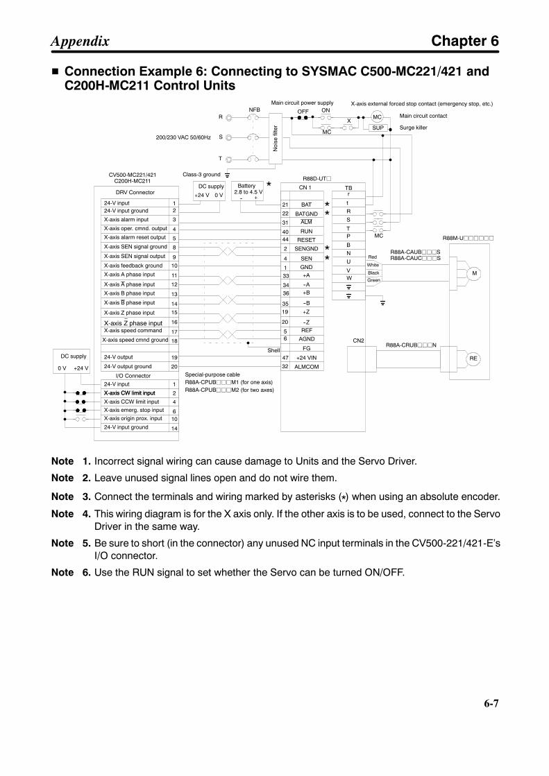
6-7
H Connection Example 6: Connecting to SYSMAC C500-MC221/421 andC200H-MC211 Control Units
19
ALM31
CN2
BAT t
R
S
TP
B
TB
M
RE
R88D-UTj
R88M-Ujjjjjj
R88A-CRUBjjjN
CN 1
BATGND
--B
SEN
+24 VIN
RUN
RESET
+Z
--Z
21
35
4
47
4044
20
5
22
R88A-CAUBjjjSR88A-CAUCjjjSRed
White
Black
Green
Class-3 ground
R
T
Noi
sefil
ter
NFB
S
OFF ONMain circuit power supply
SUP
MC
MC
X
N
U
VW
MC
r
FGShell
REF
+B36
CV500-MC221/421C200H-MC211
200/230 VAC 50/60Hz
2
4
8
9
10
11
13
14
15
16
19
20
1
2
4
3
5
12
610
14
1 GND
1
17
18
0 V +24 V
SENGND2
+A33
--A34
32 ALMCOM
6 AGND
0 V+24 V
Main circuit contact
Surge killer
DRV Connector
24-V input24-V input ground
X-axis alarm input
X-axis oper. cmnd. output
X-axis alarm reset output
X-axis SEN signal ground
X-axis SEN signal output
X-axis feedback ground
X-axis A phase input
X-axis A phase input
X-axis B phase input
X-axis B phase input
X-axis Z phase input
X-axis Z phase input
**
**
X-axis speed command
X-axis speed cmnd ground
24-V output
24-V output ground
I/O Connector24-V input
X-axis CW limit inputX-axis CW limit input
X-axis CCW limit inputX-axis emerg. stop inputX-axis origin prox. input
24-V input ground
X-axis external forced stop contact (emergency stop, etc.)
R88A-CPUBjjjM1 (for one axis)Special-purpose cable
R88A-CPUBjjjM2 (for two axes)
DC supply Battery2.8 to 4.5 V
DC supply
*+--
Note 1. Incorrect signal wiring can cause damage to Units and the Servo Driver.
Note 2. Leave unused signal lines open and do not wire them.
Note 3. Connect the terminals and wiring marked by asterisks (*) when using an absolute encoder.
Note 4. This wiring diagram is for the X axis only. If the other axis is to be used, connect to the ServoDriver in the same way.
Note 5. Be sure to short (in the connector) any unused NC input terminals in the CV500-221/421-E’sI/O connector.
Note 6. Use the RUN signal to set whether the Servo can be turned ON/OFF.
Appendix Chapter 6
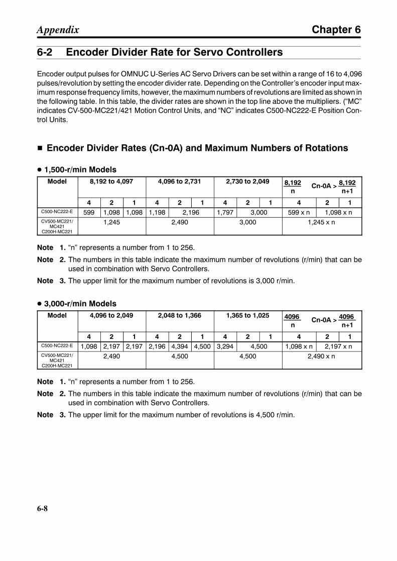
6-8
6-8
6-2 Encoder Divider Rate for Servo Controllers
Encoder output pulses for OMNUC U-Series AC Servo Drivers can be set within a range of 16 to 4,096pulses/revolution by setting the encoder divider rate. Depending on the Controller’s encoder input max-imum response frequency limits, however, the maximum numbers of revolutions are limited as shown inthe following table. In this table, the divider rates are shown in the top line above the multipliers. (“MC”indicates CV-500-MC221/421 Motion Control Units, and “NC” indicates C500-NC222-E Position Con-trol Units.
H Encoder Divider Rates (Cn-0A) and Maximum Numbers of Rotations
D 1,500-r/min ModelsModel 8,192 to 4,097 4,096 to 2,731 2,730 to 2,049 8,192
n Cn-0A > 8,192
n+1
4 2 1 4 2 1 4 2 1 4 2 1C500-NC222-E 599 1,098 1,098 1,198 2,196 1,797 3,000 599 x n 1,098 x nCV500-MC221/
MC421C200H-MC221
1,245 2,490 3,000 1,245 x n
Note 1. “n” represents a number from 1 to 256.
Note 2. The numbers in this table indicate the maximum number of revolutions (r/min) that can beused in combination with Servo Controllers.
Note 3. The upper limit for the maximum number of revolutions is 3,000 r/min.
D 3,000-r/min ModelsModel 4,096 to 2,049 2,048 to 1,366 1,365 to 1,025 4096
n Cn-0A > 4096
n+1
4 2 1 4 2 1 4 2 1 4 2 1C500-NC222-E 1,098 2,197 2,197 2,196 4,394 4,500 3,294 4,500 1,098 x n 2,197 x nCV500-MC221/
MC421C200H-MC221
2,490 4,500 4,500 2,490 x n
Note 1. “n” represents a number from 1 to 256.
Note 2. The numbers in this table indicate the maximum number of revolutions (r/min) that can beused in combination with Servo Controllers.
Note 3. The upper limit for the maximum number of revolutions is 4,500 r/min.
Appendix Chapter 6
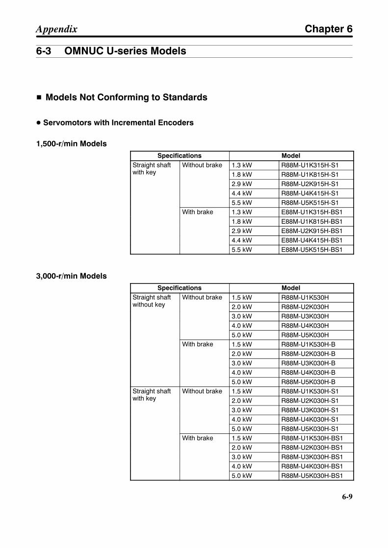
6-9
6-3 OMNUC U-series Models
H Models Not Conforming to Standards
D Servomotors with Incremental Encoders
1,500-r/min ModelsSpecifications Model
Straight shaftwith key
Without brake 1.3 kW R88M-U1K315H-S1Straight shaftwith key
Without brake1.8 kW R88M-U1K815H-S12.9 kW R88M-U2K915H-S14.4 kW R88M-U4K415H-S15.5 kW R88M-U5K515H-S1
With brake 1.3 kW E88M-U1K315H-BS1With brake1.8 kW E88M-U1K815H-BS12.9 kW E88M-U2K915H-BS14.4 kW E88M-U4K415H-BS15.5 kW E88M-U5K515H-BS1
3,000-r/min ModelsSpecifications Model
Straight shaftwithout key
Without brake 1.5 kW R88M-U1K530HStraight shaftwithout key
Without brake2.0 kW R88M-U2K030H3.0 kW R88M-U3K030H4.0 kW R88M-U4K030H5.0 kW R88M-U5K030H
With brake 1.5 kW R88M-U1K530H-BWith brake2.0 kW R88M-U2K030H-B3.0 kW R88M-U3K030H-B4.0 kW R88M-U4K030H-B5.0 kW R88M-U5K030H-B
Straight shaftwith key
Without brake 1.5 kW R88M-U1K530H-S1Straight shaftwith key
Without brake2.0 kW R88M-U2K030H-S13.0 kW R88M-U3K030H-S14.0 kW R88M-U4K030H-S15.0 kW R88M-U5K030H-S1
With brake 1.5 kW R88M-U1K530H-BS1With brake2.0 kW R88M-U2K030H-BS13.0 kW R88M-U3K030H-BS14.0 kW R88M-U4K030H-BS15.0 kW R88M-U5K030H-BS1
Appendix Chapter 6
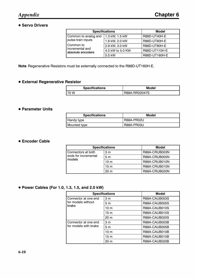
6-10
6-10
D Servo DriversSpecifications Model
Common to analog andpulse-train inputs
1.3 kW, 1.5 kW R88D-UT40H-ECommon to analog andpulse-train inputs
Common to1.8 kW, 2.0 kW R88D-UT60H-E
Common toincremental and
2.9 kW, 3.0 kW R88D-UT80H-Eincremental andabsolute encoders 4.0 kW to 5.0 KW R88D-UT110H-Eabsolute encoders
5.5 kW R88D-UT160H-E
Note Regenerative Resistors must be externally connected to the R88D-UT160H-E.
D External Regenerative ResistorSpecifications Model
70 W R88A-RR22047S
D Parameter UnitsSpecifications Model
Handy type R88A-PR02UMounted type R88A-PR03U
D Encoder CableSpecifications Model
Connectors at bothends for incremental
3 m R88A-CRUB003NConnectors at bothends for incrementalmodels
5 m R88A-CRUB005Nmodels
10 m R88A-CRUB010N15 m R88A-CRUB015N20 m R88A-CRUB020N
D Power Cables (For 1.0, 1.3, 1.5, and 2.0 kW)Specifications Model
Connector at one endfor models without
3 m R88A-CAUB003SConnector at one endfor models withoutbrake
5 m R88A-CAUB005Sbrake
10 m R88A-CAUB010S15 m R88A-CAUB015S20 m R88A-CAUB020S
Connector at one endfor models with brake
3 m R88A-CAUB003BConnector at one endfor models with brake 5 m R88A-CAUB005B
10 m R88A-CAUB010B15 m R88A-CAUB015B20 m R88A-CAUB020B
Appendix Chapter 6
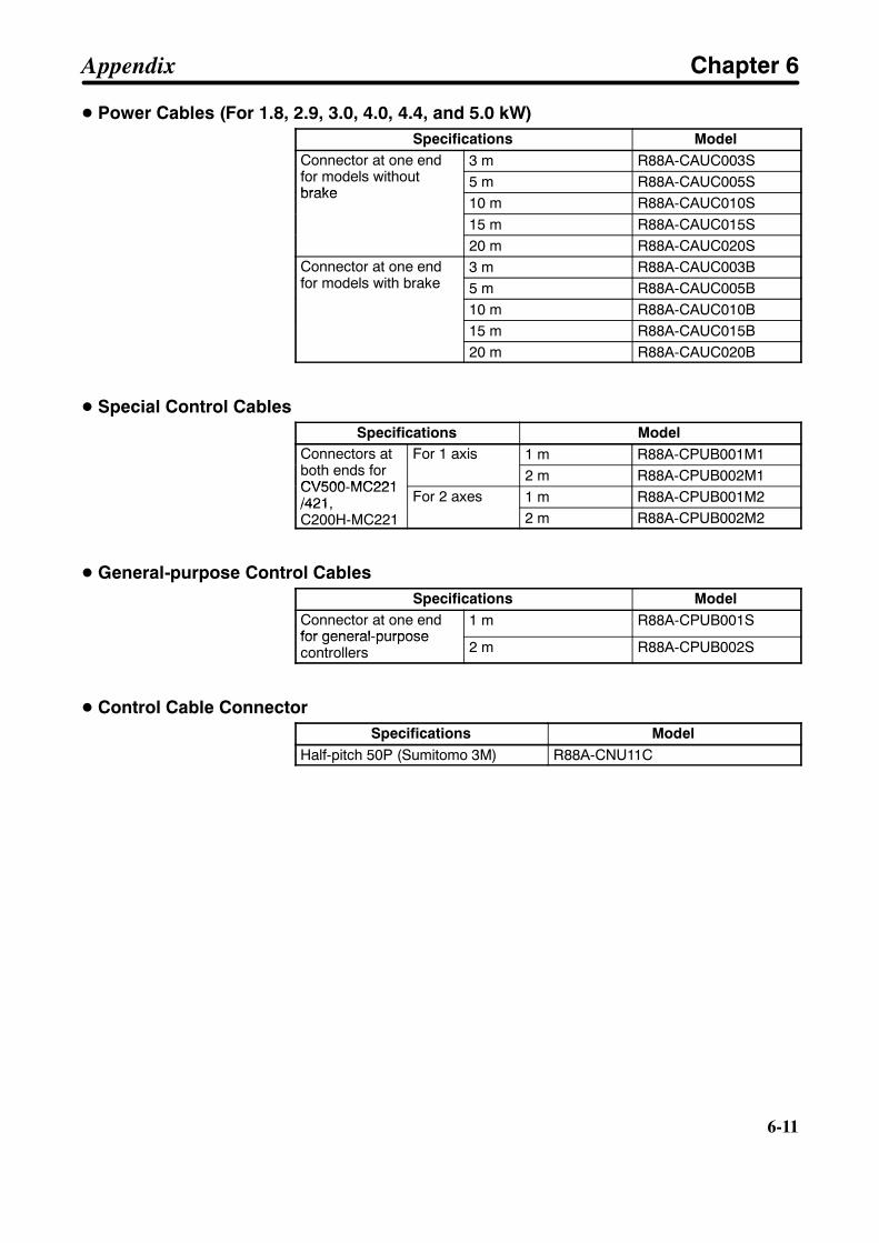
6-11
D Power Cables (For 1.8, 2.9, 3.0, 4.0, 4.4, and 5.0 kW)Specifications Model
Connector at one endfor models without
3 m R88A-CAUC003SConnector at one endfor models withoutbrake
5 m R88A-CAUC005Sbrake
10 m R88A-CAUC010S15 m R88A-CAUC015S20 m R88A-CAUC020S
Connector at one endfor models with brake
3 m R88A-CAUC003BConnector at one endfor models with brake 5 m R88A-CAUC005B
10 m R88A-CAUC010B15 m R88A-CAUC015B20 m R88A-CAUC020B
D Special Control CablesSpecifications Model
Connectors atboth ends for
For 1 axis 1 m R88A-CPUB001M1Connectors atboth ends forCV500-MC221
For 1 axis2 m R88A-CPUB002M1
CV500-MC221/421, For 2 axes 1 m R88A-CPUB001M2/421,C200H-MC221
For 2 axes2 m R88A-CPUB002M2
D General-purpose Control CablesSpecifications Model
Connector at one endfor general-purpose
1 m R88A-CPUB001Sfor general-purposecontrollers 2 m R88A-CPUB002S
D Control Cable ConnectorSpecifications Model
Half-pitch 50P (Sumitomo 3M) R88A-CNU11C
Appendix Chapter 6

6-12
6-12
H Models Conforming to EC Directives
D Servomotors with Incremental Encoders
1,500-r/min ModelsSpecifications Model
Straightshaft with
Withoutbrake
Without oilseal
1.3 kW R88M-U1K315V-S1Straightshaft withkey
Withoutbrake
Without oilseal 1.8 kW R88M-U1K815V-S1
key2.9 kW R88M-U2K915V-S14.4 kW R88M-U4K415V-S15.5 kW R88M-U5K515V-S1
With oilseal
1.3 kW R88M-U1K315V-OS1With oilseal 1.8 kW R88M-U1K815V-OS1
2.9 kW R88M-U2K915V-OS14.4 kW R88M-U4K415V-OS15.5 kW R88M-U5K515V-OS1
With brake Without oilseal
1.3 kW E88M-U1K315V-BS1With brake Without oilseal 1.8 kW E88M-U1K815V-BS1
2.9 kW E88M-U2K915V-BS14.4 kW E88M-U4K415V-BS15.5 kW E88M-U5K515V-BS1
With oilseal
1.3 kW E88M-U1K315V-BOS1With oilseal 1.8 kW E88M-U1K815V-BOS1
2.9 kW E88M-U2K915V-BOS14.4 kW E88M-U4K415V-BOS15.5 kW E88M-U5K515V-BOS1
Appendix Chapter 6
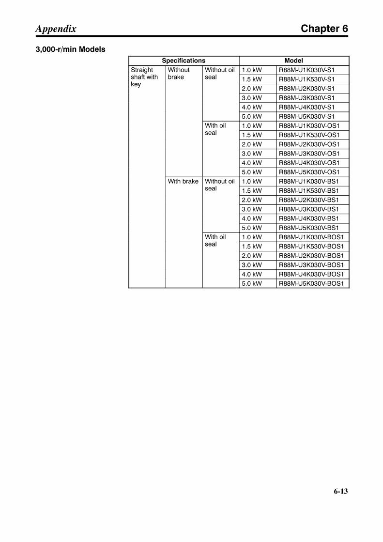
6-13
3,000-r/min ModelsSpecifications Model
Straightshaft with
Withoutbrake
Without oilseal
1.0 kW R88M-U1K030V-S1Straightshaft withkey
Withoutbrake
Without oilseal 1.5 kW R88M-U1K530V-S1
key2.0 kW R88M-U2K030V-S13.0 kW R88M-U3K030V-S14.0 kW R88M-U4K030V-S15.0 kW R88M-U5K030V-S1
With oilseal
1.0 kW R88M-U1K030V-OS1With oilseal 1.5 kW R88M-U1K530V-OS1
2.0 kW R88M-U2K030V-OS13.0 kW R88M-U3K030V-OS14.0 kW R88M-U4K030V-OS15.0 kW R88M-U5K030V-OS1
With brake Without oilseal
1.0 kW R88M-U1K030V-BS1With brake Without oilseal 1.5 kW R88M-U1K530V-BS1
2.0 kW R88M-U2K030V-BS13.0 kW R88M-U3K030V-BS14.0 kW R88M-U4K030V-BS15.0 kW R88M-U5K030V-BS1
With oilseal
1.0 kW R88M-U1K030V-BOS1With oilseal 1.5 kW R88M-U1K530V-BOS1
2.0 kW R88M-U2K030V-BOS13.0 kW R88M-U3K030V-BOS14.0 kW R88M-U4K030V-BOS15.0 kW R88M-U5K030V-BOS1
Appendix Chapter 6

6-14
6-14
D Servomotors with Absolute Encoders
1,500-r/min ModelsSpecifications Model
Straightshaft with
Withoutbrake
Without oilseal
1.3 kW R88M-U1K315X-Straightshaft withkey
Withoutbrake
Without oilseal 1.8 kW R88M-U1K815X
key2.9 kW R88M-U2K915X4.4 kW R88M-U4K415X5.5 kW R88M-U5K515X
With oilseal
1.3 kW R88M-U1K315X-OWith oilseal 1.8 kW R88M-U1K815X-O
2.9 kW R88M-U2K915X-O4.4 kW R88M-U4K415X-O5.5 kW R88M-U5K515X-O
With brake Without oilseal
1.3 kW E88M-U1K315X-BS1With brake Without oilseal 1.8 kW E88M-U1K815X-BS1
2.9 kW E88M-U2K915X-BS14.4 kW E88M-U4K415X-BS15.5 kW E88M-U5K515X-BS1
With oilseal
1.3 kW E88M-U1K315X-BOS1With oilseal 1.8 kW E88M-U1K815X-BOS1
2.9 kW E88M-U2K915X-BOS14.4 kW E88M-U4K415X-BOS15.5 kW E88M-U5K515X-BOS1
Appendix Chapter 6
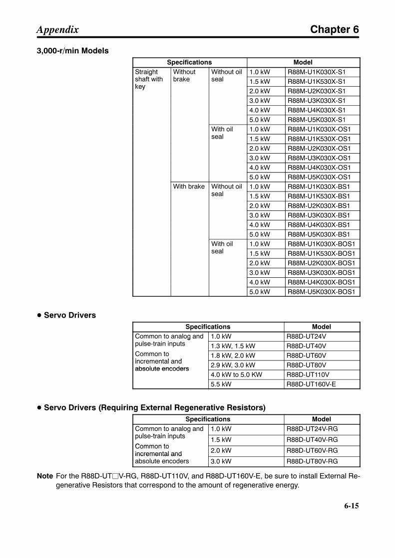
6-15
3,000-r/min ModelsSpecifications Model
Straightshaft with
Withoutbrake
Without oilseal
1.0 kW R88M-U1K030X-S1Straightshaft withkey
Withoutbrake
Without oilseal 1.5 kW R88M-U1K530X-S1
key2.0 kW R88M-U2K030X-S13.0 kW R88M-U3K030X-S14.0 kW R88M-U4K030X-S15.0 kW R88M-U5K030X-S1
With oilseal
1.0 kW R88M-U1K030X-OS1With oilseal 1.5 kW R88M-U1K530X-OS1
2.0 kW R88M-U2K030X-OS13.0 kW R88M-U3K030X-OS14.0 kW R88M-U4K030X-OS15.0 kW R88M-U5K030X-OS1
With brake Without oilseal
1.0 kW R88M-U1K030X-BS1With brake Without oilseal 1.5 kW R88M-U1K530X-BS1
2.0 kW R88M-U2K030X-BS13.0 kW R88M-U3K030X-BS14.0 kW R88M-U4K030X-BS15.0 kW R88M-U5K030X-BS1
With oilseal
1.0 kW R88M-U1K030X-BOS1With oilseal 1.5 kW R88M-U1K530X-BOS1
2.0 kW R88M-U2K030X-BOS13.0 kW R88M-U3K030X-BOS14.0 kW R88M-U4K030X-BOS15.0 kW R88M-U5K030X-BOS1
D Servo DriversSpecifications Model
Common to analog andpulse-train inputs
1.0 kW R88D-UT24VCommon to analog andpulse-train inputs
Common to1.3 kW, 1.5 kW R88D-UT40V
Common toincremental and
1.8 kW, 2.0 kW R88D-UT60Vincremental andabsolute encoders 2.9 kW, 3.0 kW R88D-UT80Vabsolute encoders
4.0 kW to 5.0 KW R88D-UT110V5.5 kW R88D-UT160V-E
D Servo Drivers (Requiring External Regenerative Resistors)Specifications Model
Common to analog andpulse-train inputs
1.0 kW R88D-UT24V-RGpulse-train inputs
Common to1.5 kW R88D-UT40V-RG
Common toincremental and 2.0 kW R88D-UT60V-RGincremental andabsolute encoders 3.0 kW R88D-UT80V-RG
Note For the R88D-UTjV-RG, R88D-UT110V, and R88D-UT160V-E, be sure to install External Re-generative Resistors that correspond to the amount of regenerative energy.
Appendix Chapter 6
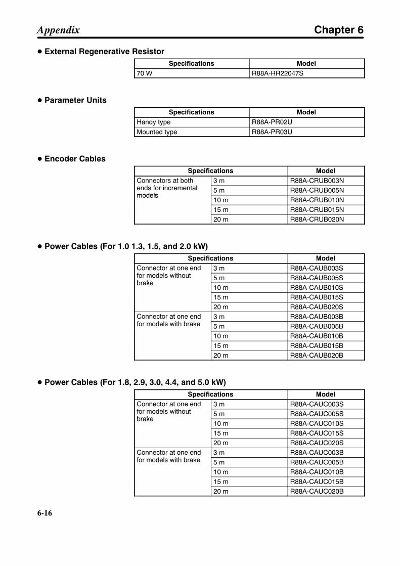
6-16
6-16
D External Regenerative ResistorSpecifications Model
70 W R88A-RR22047S
D Parameter UnitsSpecifications Model
Handy type R88A-PR02UMounted type R88A-PR03U
D Encoder CablesSpecifications Model
Connectors at bothends for incremental
3 m R88A-CRUB003NConnectors at bothends for incrementalmodels
5 m R88A-CRUB005Nmodels
10 m R88A-CRUB010N15 m R88A-CRUB015N20 m R88A-CRUB020N
D Power Cables (For 1.0 1.3, 1.5, and 2.0 kW)Specifications Model
Connector at one endfor models without
3 m R88A-CAUB003SConnector at one endfor models withoutbrake
5 m R88A-CAUB005Sbrake
10 m R88A-CAUB010S15 m R88A-CAUB015S20 m R88A-CAUB020S
Connector at one endfor models with brake
3 m R88A-CAUB003BConnector at one endfor models with brake 5 m R88A-CAUB005B
10 m R88A-CAUB010B15 m R88A-CAUB015B20 m R88A-CAUB020B
D Power Cables (For 1.8, 2.9, 3.0, 4.4, and 5.0 kW)Specifications Model
Connector at one endfor models without
3 m R88A-CAUC003SConnector at one endfor models withoutbrake
5 m R88A-CAUC005Sbrake
10 m R88A-CAUC010S15 m R88A-CAUC015S20 m R88A-CAUC020S
Connector at one endfor models with brake
3 m R88A-CAUC003BConnector at one endfor models with brake 5 m R88A-CAUC005B
10 m R88A-CAUC010B15 m R88A-CAUC015B20 m R88A-CAUC020B
Appendix Chapter 6

6-17
D Special Control CablesSpecifications Model
Connectors atboth ends for
For 1 axis 1 m R88A-CPUB001M1Connectors atboth ends forCV500-MC221
For 1 axis2 m R88A-CPUB002M1
CV500-MC221/421, For 2 axes 1 m R88A-CPUB001M2/421,C200H-MC221
For 2 axes2 m R88A-CPUB002M2
D General-purpose Control CablesSpecifications Model
Connector at one endfor general-purpose
1 m R88A-CPUB001Sfor general-purposecontrollers 2 m R88A-CPUB002S
D Control Cable ConnectorSpecifications Model
Half-pitch 50P (Sumitomo 3M) R88A-CNU11C
Appendix Chapter 6

6-18
6-18
6-4 Combinations of Servo Drivers and Servomotors
Models Not Conforming to StandardsServo Drivers Servomotors with
incremental encodersRated motor revolution Motor capacity
R88D-UT40H-E R88M-U1K315H-jS1 1,500 r/min 1.3 kWR88D-UT40H-ER88M-U1K530H-j 3,000 r/min 1.5 kW
R88D-UT60H-E R88M-U1K815H-jS1 1,500 r/min 1.8 kWR88D-UT60H-ER88M-U2K030H-j 3,000 r/min 2.0 kW
R88D-UT80H-E R88M-U2K915H-jS1 1,500 r/min 2.9 kWR88D-UT80H-ER88M-U3K030H-j 3,000 r/min 3.0 kW
R88D-UT110H-E R88M-U4K030H-j 3,000 r/min 4.0 kWR88D-UT110H-ER88M-U4K415H-jS1 1,500 r/min 4.4 kWR88M-U5K030H-j 3,000 r/min 5.0 kW
R88D-UT160H-E R88M-U5K515H-jS1 1,500 r/min 5.5 kW
Models Conforming to EC DirectivesServo Drivers Servomotors Rated motor
revolutionMotor capacityServo Drivers
With incrementalencoders
With absoluteencoders
Rated motorrevolution
Motor capacity
R88D-UT24V-j R88M-U1K030V-jS1 R88M-U1K030X-jS1 3,000 r/min 1.0 kWR88D-UT40V-j R88M-U1K315V-jS1 R88M-U1K315X-jS1 1,500 r/min 1.3 kWR88D-UT40V-j
R88M-U1K530V-jS1 R88M-U1K530X-jS1 3,000 r/min 1.5 kWR88D-UT60V-j R88M-U1K815V-jS1 R88M-U1K815X-jS1 1,500 r/min 1.8 kWR88D-UT60V-j
R88M-U2K030V-jS1 R88M-U2K030X-jS1 3,000 r/min 2.0 kWR88D-UT80V-j R88M-U2K915V-jS1 R88M-U2K915X-jS1 1,500 r/min 2.9 kWR88D-UT80V-j
R88M-U3K030V-jS1 R88M-U3K030X-jS1 3,000 r/min 3.0 kWR88D-UT110V R88M-U4K415V-jS1 R88M-U4K415X-jS1 1,500 r/min 4.4 kWR88D-UT110V
R88M-U4K030V-jS1 R88M-U4K030X-jS1 3,000 r/min 4.0 kWR88M-U5K030V-jS1 R88M-U5K030X-jS1 3,000 r/min 5.0 kW
R88D-UT160V-E R88M-U5K515V-jS1 R88M-U5K515X-jS1 1,500 r/min 5.5 kW
Note It is necessary to set Cn-2A (Motor Selection) according to the motor capacities. For setting val-ues, refer to 3-3-2 Setting and Checking User Parameters.
Appendix Chapter 6
Related Documents


