I4-E-01 Language User's

Welcome message from author
This document is posted to help you gain knowledge. Please leave a comment to let me know what you think about it! Share it to your friends and learn new things together.
Transcript

I4-E-01
Language
User's


Copyright NoticeThe information contained herein is the property of Omron Adept Technologies, Inc., and shall not bereproduced in whole or in part without prior written approval of Omron Adept Technologies, Inc. Theinformation herein is subject to change without notice and should not be construed as a commitment byOmron Adept Technologies, Inc. The documentation is periodically reviewed and revised.
Omron Adept Technologies, Inc., assumes no responsibility for any errors or omissions in thedocumentation. Critical evaluation of the documentation by the user is welcomed. Your comments assistus in preparation of future documentation. Please submit your comments to: [email protected].
Copyright © 1994 - 2016 by Omron Adept Technologies, Inc.
Created in the United States of America
eV+Language User's Guide, v2.x, 18318-000 Rev A
Page 3

Table Of Contents
eV+ Language User's Guide Introduction 9Introduction to the eV+ Language User's Guide 10Compatibility 10Manual Overview 10eV+ Release Notes 11Related Publications 11Dangers, Warnings, Cautions, and Notes 12Safety 13Notations and Conventions 15
Programming eV+ 17Creating a Program 19eV+ Program Types 20Format of Programs 22Executing Programs 24Program Stacks 25Flow of Program Execution 27Subroutines 28
The SEE Editor and Debugger 35
Data Types and Operators 37Introduction 39String Data Type 40Real and Integer Data Types 42Location Data Types 44Arrays 45Variable Classes 47Operators 51String Operator 55Order of Evaluation 56
Program Control 57Introduction 59
eV+Language User's Guide, v2.x, 18318-000 Rev A
Page 5

Unconditional Branch Instructions 60Program Interrupt Instructions 62Logical (Boolean) Expressions 68Conditional Branching Instructions 69Looping Structures 72Summary of Program Control Keywords 76
Functions 79Using Functions 81String-Related Functions 82Location, Motion, and External Encoder Functions 84Numeric Value Functions 85Logical Functions 87System Control Functions 88
Switches and Parameters 91Introduction 93Parameters 94Switches 96
Motion Control Operations 99Introduction 101Location Variables 102Creating and Altering Location Variables 109Motion Control Instructions 116Tool Transformations 124Summary of Motion Keywords 126
Input/Output Operations 135Digital I/O 137Serial and Disk I/O Basics 139Disk I/O 143Advanced Disk Operations 148Serial Line I/O 152DeviceNet 156Summary of I/O Operations 157
eV+Language User's Guide, v2.x, 18318-000 Rev A
Page 6

Graphics Programming 161Creating Windows 162Monitoring Events 165Building a Menu Structure 167Creating Buttons 170Creating a Slide Bar 172Graphics Programming Considerations 174Communicating With the System Windows 176Additional Graphics Instructions 178
Programming the Omron Adept T20 Pendant 179Introduction 179Writing to the Pendant Display 180Detecting User Input 181Programming Example: Pendant Menu 183
Conveyor Tracking 187Introduction to Conveyor Tracking 189Installation 190Calibration 191Basic Programming Concepts 192Conveyor-Tracking Programming 199Sample Programs 201
Multiprocessor Systems 203
Example eV+ Programs 205Introduction 207Pick and Place 208Menu Program 212
External Encoder Device 215Introduction 217Parameters 218Device Setup 219Reading Device Data 220
eV+Language User's Guide, v2.x, 18318-000 Rev A
Page 7

Character Sets 223
eV+Language User's Guide, v2.x, 18318-000 Rev A
Page 8

eV+ Language User's Guide IntroductionThe following topics are described in this chapter:
Introduction to the eV+ Language User's Guide 10Compatibility 10Manual Overview 10eV+ Release Notes 11Related Publications 11Dangers, Warnings, Cautions, and Notes 12Safety 13Notations and Conventions 15
eV+ Language User's Guide Introduction
eV+Language User's Guide, v2.x, 18318-000 Rev A
Page 9

Introduction to the eV+ Language User's GuideeV+ is a computer-based control system and programming language designed specifically foruse with Omron Adept Technologies, Inc. industrial robots, vision systems, andmotion-control systems.
As a real-time system, continuous trajectory computation by eV+ permits complex motionsto be executed quickly, with efficient use of system memory and reduction in overall systemcomplexity. The eV+ system continuously generates robot-control commands and canconcurrently interact with an operator, permitting on-line program generation andmodification.
eV+ provides all the functionality of modern high-level programming languages, including:
l Callable subroutines
l Control structures
l Multitasking environment
l Recursive, reentrant program execution
CompatibilityThis manual is for use with eV+ v2.x and later. This manual covers the basic eV+ system. Ifyour system is equippedwith optional vision, see the ACE Sight User's Guide and the ACESight Reference Guide, for details on your vision system.
Manual OverviewThis manual details the concepts and strategies of programming in eV+. Material coveredincludes:
l Functional overview of eV+
l A description of the data types used in eV+
l A description of the system parameters and switches
l Basic programming of eV+ systems
l Editing and debugging eV+ programs
l Communication with peripheral devices
l Communication with the manual control pendant ("the pendant")
l Conveyor tracking feature
l Example programs
Introduction to the eV+ Language User's Guide
eV+Language User's Guide, v2.x, 18318-000 Rev A
Page 10

l Using tool transformations
l Accessing external encoders
Many eV+ keywords are shown in abbreviated form in this user guide. See the eV+Language Reference Guide for complete details on all eV+ keywords.
eV+ Release NotesFor information on new features or enhanced keywords listed by eV+ software release,select a link below:
eV+ v2.x Release Notes
Related PublicationsIn addition to this manual, have the following publications handy as you set up and programyour Omron Adept automation system.
Manual Material Covered
eV+ Language Reference Guide This manual provides a complete description ofthe keywords used in the basic eV+ system.
eV+ Operating System User'sGuide
This manual provides a description of the eV+operating system. Loading, storing, andexecuting programs are covered in this manual.
eV+ Operating SystemReference Guide
This manual provides descriptions of the eV+operating system commands (known asmonitorcommands).
ACE User's Guide This manual describes the ACE graphical userinterface, which is used to program your Adeptmotion system.
ACE Reference Guide This manual provides descriptions of thecommands available with systems that includethe optional ACE Sight vision system.
Adept SmartController EX User'sGuide
This manual detailsthe installation,configuration, andmaintenance of yourcontroller. The controller must be set up andconfigured before control programs will executeproperly.
Related Publications
eV+ Release Notes
eV+Language User's Guide, v2.x, 18318-000 Rev A
Page 11

Manual Material Covered
Adept SmartMotion Developer'sGuide
Adept SmartMotion InstallationGuide
These manuals describe the installation,configuration, and tuning of an Adept motionsystem.
Adept T20 Pendant User’s Guide This manual describes the basic use of the T20manual control pendant.
Dangers, Warnings, Cautions, and NotesThere are six levels of special alert notation that may be used in this manual. In descendingorder of importance, they are:
DANGER: This indicates an imminently hazardous electrical situationwhich, if not avoided, will result in death or serious injury.
DANGER: This indicates an imminently hazardous situation which, ifnot avoided, will result in death or serious injury.
WARNING: This indicates a potentially hazardous electrical situationwhich, if not avoided, could result in serious injury or major damage tothe equipment.
WARNING: This indicates a potentially hazardous situation which, ifnot avoided, could result in serious injury or major damage to theequipment.
Dangers, Warnings, Cautions, and Notes
eV+Language User's Guide, v2.x, 18318-000 Rev A
Page 12

CAUTION: This indicates a situation which, if not avoided, could resultin minor injury or damage to the equipment.
NOTE: This provides supplementary information, emphasizes a point or procedure, orgives a tip for easier operation.
SafetyThe following sections discuss the safety measures you must take while operating an OmronAdept robot.
Reading and Training for System Users
Omron Adept robot systems include computer-controlledmechanisms that are capable ofmoving at high speeds and exerting considerable force. Like all robot systems and industrialequipment, they must be treated with respect by the system user.
Impacts and Trapping Points
Omron Adept recommends that you read the American National Standard for IndustrialRobot Systems-Safety Requirements, published by the Robotic Industries Association inconjunction with the American National Standards Institute. The publication, ANSI/RIAR15.06-1986, contains guidelines for robot system installation, safeguarding, maintenance,testing, startup, and operator training. The document is available from the AmericanNational Standards Institute, 1430 Broadway, New York, NY 10018.
System Safeguards
Safeguards should be an integral part of robot workcell design, installation, operator training,and operating procedures. Omron Adept robot systems have various communicationfeatures to aid you in constructing system safeguards. These include remote emergencystop circuitry and digital input and output lines.
Safety
eV+Language User's Guide, v2.x, 18318-000 Rev A
Page 13

Computer-Controlled Robots
Omron Adept robots are computer controlled, and the program that is running the robot maycause it to move at times or along paths you may not anticipate. Your system should beequippedwith indicator lights that tell operators when the system is active. The Front Panel(FP) provides these lights. When the White HIGH POWER enable light on the FP or T20Pendant is illuminated, do not enter the workcell because the robot may move unexpectedly.
High Power Enable Light
Manually Controlled Robots
Omron Adept robots can also be controlledmanually when the white HIGH POWER enablelight on the front of the controller is illuminated. When this light is lit, robot motion can beinitiated from the terminal or the pendant (see the T20 Pendant User's Guide for moreinformation). Before you enter the workspace, turn the keyswitch to manual mode and takethe key (or the T20 pendant) with you. This will prevent anyone else from initiatingunexpected robot motions from the terminal keyboard.
Other Computer-Controlled Devices
In addition, these systems can be programmed to control equipment or devices other thanthe robot. As with the robot, the program controlling these devices may cause them tooperate at times not anticipated by personnel. Make sure that safeguards are in place toprevent personnel from entering the workcell.
Safety
eV+Language User's Guide, v2.x, 18318-000 Rev A
Page 14

WARNING: Entering the robot workcell when the white HIGH POWERenable light is illuminated can result in severe injury.
Omron Adept Technologies, Inc. recommends the use of additional safety features such aslight curtains, safety gates, or safety floor mats to prevent entry to the workcell while HIGHPOWER is enabled. These devices may be connected using the robot's remote emergencystop circuitry.
Notations and ConventionsThis section describes various notations used throughout this manual and conventionsobserved by the eV+ system.
Uppercase and Lowercase Letters
You will notice that a mixture of uppercase (capital) and lowercase letters is used throughoutthis manual when eV+ operations are presented. eV+ keywords are shown in uppercaseletters. Parameters to keywords are shown in lowercase. Many eV+ keywords have optionalparameters and/or elements. Required keyword elements and parameters are shown inboldface type. Optional keyword elements and parameters are shown in normal type. Ifthere is a comma following an optional parameter, the commamust be retained if theparameter is omitted, unless nothing follows.
Note that the commas preceding the number 300 must be present to correctly relate thenumber with a Z-direction change.
Numeric Arguments
All numbers in this manual are decimal unless otherwise noted. Binary numbers are shownas ^B, octal numbers as ^, and hexadecimal numbers as ^H.
Several types of numeric arguments can appear in commands and instructions. For eachtype of argument, the value can generally be specified by a numeric constant, a variablename, or a mathematical expression.
There are some restrictions on the numeric values that are accepted by eV+. The followingrules determine how a value will be interpreted in the various situations described.
1. Distances are used to define locations to which the robot is to move. The unit ofmeasure for distances is the millimeter, although units are never explicitly entered forany value. Values entered for distances can be positive or negative.1
2. Angles in degrees are entered to define andmodify orientations the robot is toassume at named locations, and to describe angular positions of robot joints. Anglevalues can be positive or negative, with their magnitudes limited by 180 degrees or360 degrees depending on the usage.
Notations and Conventions
eV+Language User's Guide, v2.x, 18318-000 Rev A
Page 15

3. Joint numbers are integers from one up to the number of joints in the robot,including the hand if a servo-controlled hand is operational. For Omron Adept SCARArobots, joint numbering starts with the rotation about the base, referred to as joint 1.For mechanisms controlled by AdeptMotion, see the device module documentation forjoint numbering.
4. Signal numbers are used to identify digital (on/off) signals. They are alwaysconsidered as integer values with magnitudes in the ranges 1 to 8, 33 to 512, 1001 to1012, 1032 to 1512, 2001 to 2512, or 3001 to 3004. A negative signal numberindicates an off state.
5. Integer arguments can be satisfied with real values (that is, values with integer andfractional parts). When an integer is required, the value is rounded and the resultinginteger is used.
6. Arguments indicated as being scalar variables can be satisfied with a real value(that is, one with integer and fractional parts) except where noted. Scalars can rangefrom -9.22*1018 to 9.22*1018 in value (displayed as -9.22E18 and 9.22E18).2
1See the IPS instruction for a special case of specifying robot speed in inches per second.
2Numbers specifically declared to be double-precision values can range from -1.8*10-307 to1.8*10-307.
Notations and Conventions
eV+Language User's Guide, v2.x, 18318-000 Rev A
Page 16

Programming eV+The following topics are described in this chapter:
Creating a Program 19eV+ Program Types 20Format of Programs 22Executing Programs 24Program Stacks 25Flow of Program Execution 27Subroutines 28
Programming eV+
eV+Language User's Guide, v2.x, 18318-000 Rev A
Page 17

Programming eV+
eV+Language User's Guide, v2.x, 18318-000 Rev A
Page 18

Creating a ProgramBeginning with eV+ version v2.x, eV+ programs are created (and debugged) through theACE user interface. The eV+ Editor and Debugger tools provide a full-featured environmentfor creating, editing and debugging eV+ programs. For more details, see the chapterProgramming ACE in the ACE User's Guide.
Program and Variable Name Requirements
Program and variable names can have up to 15 characters. Namesmust begin with a letterand can be followed by any sequence of letters, numbers, periods, and underline characters.Letters used in program names can be entered in either lowercase or uppercase. eV+ alwaysdisplays program and variable names in lowercase.
Creating a Program
eV+Language User's Guide, v2.x, 18318-000 Rev A
Page 19
eV+ Program TypesThere are two types of eV+ programs:
l Executable Programs
l Command Programs
Executable programs are described in this section. Command programs are similar to MS-DOSbatch programs or UNIX scripts, and they are described in the eV+ Operating System User'sGuide.
Executable Programs
There are two classes of executable programs: robot control programs and general programs.
Robot Control Programs
A robot control program is an eV+ program that directly controls a robot or motion device. Itcan contain any of the eV+ program instructions.
Robot control programs are usually executed by program task #0, but they can be executedby any of the program tasks available in the eV+ system. Task #0 automatically attaches therobot when program execution begins. If a robot control program is executed by a task otherthan #0, however, the program must explicitly attach the robot (program tasks are describedin detail later in this chapter).
For normal execution of a robot control program, the system switch DRY.RUN must bedisabled and the robot must be attached by the robot control program. Then, any robot-related error will stop execution of the program (unless an error-recovery program has beenestablished [see REACTE in the eV+ Language Reference Guide]).1
Exclusive Control of a Robot
l Whenever a robot is attached by an active task, no other task can attach that robot orexecute instructions that affect it, except for the REACTI and BRAKE instructions. Fordetails, see Program Interrupt Instructions on page 62.
l When the robot control task stops execution for any reason, the robot is detached untilthe task resumes, at which time the task automatically attempts to reattach therobot. If another task has attached the robot in the meantime, the first task cannot beresumed.
l Task #0 always attempts to attach robot #1 when program execution begins. Noother tasks can successfully attach any robot unless an explicit ATTACH instruction isexecuted.
l Since task #0 attempts to attach robot #1, that task cannot be executed afteranother task has attached that robot. If you want another task to control the robotand you want to execute task #0, you must follow this sequence of events:
eV+ Program Types
eV+Language User's Guide, v2.x, 18318-000 Rev A
Page 20
l Start task #0.
l Have task #0 DETACH the robot.
l Start the task that will control the robot. (The program executing as task #0can start up another task.)
l Have that task ATTACH the robot.
For more information on the ATTACH andDETACH instructions, see CreatingWindowson page 162.
l Note that robots are attached even in DRY.RUN mode. In this case, motioncommands issued by the task are ignored, and no other task can access the robot.
General Programs
A general program is any program that does not control a robot. With a robot system, therecan be one or more programs executing concurrently with the robot control program. Forexample, an additional program might monitor and control external processes via theexternal digital signal lines and analog signal lines.
General programs can also communicate with the robot control program (and each other)through global variables and software signals. (General programs can also have a directeffect on the robot motion with the BRAKE instruction, although that practice is notrecommended.)
With the exception of the BRAKE instruction, a general program cannot execute anyinstruction that affects the robot motion. Also, the TOOL settings cannot be changed bygeneral programs.
Except for the robot, general-purpose control programs can access all the other features ofthe system, including ACE Sight (if it is present in the system), the (internal and external)digital signal lines, the USER serial lines, the system terminal, the disk drives, and themanual control pendant.
Note that except for the exclusion of certain instructions, general-purpose control programsare just like robot control programs. Thus, the term program is used in the remainder of thischapter when the material applies to either type of control program.
1If the system is in DRY.RUN mode while a robot control program is executing, robot motioninstructions are ignored. Also, if the robot is detached from the program, robot-related errorsdo not affect program execution.
eV+ Program Types
eV+Language User's Guide, v2.x, 18318-000 Rev A
Page 21

Format of ProgramsThis section presents the format that eV+ programsmust follow. The format of the individuallines is described, followed by the overall organization of programs. This information applies toall programs regardless of their type or intended use.
Program Lines
Each line or step of a program is interpreted by the eV+ system as a program instruction. Thegeneral format of a eV+ program step is:
step_number step_label operation ;Comment
Each item is optional and is described in detail below.
StepNumber
Each step within a program is automatically assigned a step number.Steps are numbered consecutively, and the numbers are automaticallyadjusted whenever steps are inserted or deleted. Although you will neverenter step numbers into programs, you will see them displayed by theeV+ system in several situations. Step numbers are also often referencedas line numbers.
Step Label Because step numbers change as a program evolves, they are not usefulfor identifying steps for program-controlled branching. Therefore,program steps can contain a step label. A step label is a programmer-specified integer (0 to 65535) that is placed at the start of a program lineto be referenced elsewhere in the program (usedwith GOTO statements).
Operation The operation portion of each stepmust be a valid eV+ language keywordandmay contain parameters and additional keywords. The eV+Language Reference Guide gives detailed descriptions of all the keywordsrecognized by eV+. Other instructions may be recognized if your systemincludes optional features.
Comment The semicolon character is used to indicate that the remainder of aprogram line is comment information to be ignored by eV+.
When all the elements of a program step are omitted, a blank lineresults. Blank program lines are acceptable in eV+ programs. Blank linesare often useful to space out program steps to make them easier to read.
When only the comment element of a program step is present, the step iscalled a comment line. Comments are useful to describe what theprogram does and how it interacts with other programs. Use commentsto describe and explain the intent of the sections of the programs. Suchinternal documentation will make it easier to modify and debugprograms.
Format of Programs
eV+Language User's Guide, v2.x, 18318-000 Rev A
Page 22
The example programs in this manual, and the utility programs provided by Omron Adeptwith your system, provide examples of programming format and style. Notice that OmronAdept programs contain numerous comments and blank lines.
When program lines are entered, extra spaces can be entered between any elements in theline. The eV+ editors add or delete spaces in program lines to make them conform with thestandard spacing. The editors also automatically format the lines to uppercase for allkeywords and lowercase for all user-defined names.
When you complete a program line (by entering a carriage return, moving off a line, orexiting the editor), the editor checks the syntax of the line. If the line cannot be executed, itis displayed in red in the ACE editor.
Certain control structure errors are displayed in the status bar of the editor and the programis marked as not executable. (Error checking stops at that point in the program. Thus, onlyone control structure error at a time can be detected.)
Program Organization
The first step of every eV+ program must be a .PROGRAM instruction. This instruction namesthe program, defines any arguments it receives or returns, and has the format:
.PROGRAM program_name(parameter_list) ;Comment
The program name is required, but the parameter list and comment are optional.
After the .PROGRAM line, there are only two restrictions on the order of other instructions ina program.
l AUTO, LOCAL, or GLOBAL instructions must precede any executable programinstructions. Only comment lines, blank lines, and other AUTO, LOCAL, or GLOBALinstructions are permitted between the .PROGRAM step and an AUTO, LOCAL, orGLOBAL instruction.
l The end of a program is marked by a line beginning with .END. The eV+ editorsautomatically add this line at the end of a program.1
Program Variables
eV+ uses three classes of variables: GLOBAL, LOCAL, and AUTO. These are described in detailin Variable Classes on page 47.
1The .PROGRAM and .END lines are automatically entered by the Omron Adept-supplied eV+program editors. If you use another text editor for transfer to a eV+ system, you MUST enterthese two lines. In general, any editor that produces unformatted ASCII files can be used forprogramming.
Format of Programs
eV+Language User's Guide, v2.x, 18318-000 Rev A
Page 23

Executing ProgramsWhen eV+ is actively following the instructions in a program, it is said to be executing thatprogram.
The standard eV+ system provides for simultaneous execution of up to seven differentprograms-for example, a robot control program and up to six additional programs. Theoptional eV+ extensions software provides for simultaneous execution of up to 28 programs.Execution of each program is administered as a separate program task by the system.
The way program execution is started depends upon the program task to be used and thetype of program to be executed. The following sections describe program execution in detail.
Selecting a Program Task
Task # 0 has the highest priority in the (standard) task configuration. Thus, this task isnormally used for the primary application program. For example, with a robot system, task#0 is normally used to execute the robot control program.
NOTE:As a convenience, when execution of task #0 begins, the task alwaysautomatically selects robot #1 and attaches the robot as soon as a motion relatedkeyword is encountered.
Execution of task #0 is normally started by using the EXECUTE monitor command.
The ABORTmonitor command or program instruction stops task #0 after the current robotmotion completes. The CYCLE.ENDmonitor command or program instruction can be used tostop the program at the end of its current execution cycle.
If program execution stops because of an error, a PAUSE instruction, an ABORT command orinstruction, or the monitor commands PROCEED or RETRY can be used to resume execution(see the eV+ Operating System Reference Guide for information on monitor commands).While execution is stopped, the DOmonitor command can be used to execute a singleprogram instruction (entered from the keyboard) as though it were the next instruction inthe program that is stopped.
For debugging purposes, the ACE eV+ Debugger tool can be used to execute a program onestep at a time, and to follow the flow of program execution. For details, see the ACE User'sGuide.
Execution of program tasks other than #0 is generally the same as for task #0. The followingpoints highlight the differences:
l The task number must be explicitly included in all the monitor commands and programinstructions that affect program execution, including EXECUTE, ABORT, PROCEED andRETRY.
l If the program is going to control the robot, it must explicitly ATTACH the robot beforeexecuting any instructions that control the robot.
See the section Scheduling of Program Execution Tasks for details on task scheduling.
Executing Programs
eV+Language User's Guide, v2.x, 18318-000 Rev A
Page 24

Program StacksWhen subroutine calls are made, eV+ uses aeV+n internal storage area called a stack tosave information required by the executing program. This information includes:
l The name and step number of the calling program.
l Data necessary to access subroutine arguments.
l The values of any automatic variables specified in the called program.
The eV+ system allows you to explicitly allocate storage to the stack for each program task.Thus, the amount of stack space can be tuned for a particular application to optimize the useof system memory. Stacks can be made arbitrarily large, limited only by the amount ofmemory available on your system.
Stack Requirements
When a eV+ program is executed in a given task, each program stack is allocated 32kilobytes of memory. This value can be adjusted, once the desired stack requirements aredetermined, by using the STACKmonitor command (for example, in a start-upmonitorcommand program). See the eV+ Operating System Reference Guide for information onmonitor commands.
One method of determining the stack requirements of a program task is simply to execute itsprogram. If the program runs out of stack space, it stops with the error message:
*Too many subroutine calls*
or
*Not enough stack space*
If this happens, use the STACKmonitor command to increase the stack size and then issuethe RETRYmonitor command to continue program execution. In this case, you do not needto restart the program from the beginning. (The STATUS commandwill tell you how muchstack space a failed task requested.)
Alternatively, you can start by setting a large stack size before running your program. Afterthe program has been run, and all the execution paths have been followed, use the STATUSmonitor command to look at the stack statistics for the program task. The stack MAX valueshows how much stack space your program task needs in order to execute. The stack sizecan then be set to the maximum shown, with a little extra for safety.
If it is impossible to invoke all the possible execution paths, the theoretical stack limits can becalculated from the figures provided in the following table. You can calculate the worst-casestack size by adding up the overhead for all the program calls that can be active at one time.Divide the total by 1024 to get the size in kilobytes. Use this number in the STACKmonitorcommand to set the size.
Program Stacks
eV+Language User's Guide, v2.x, 18318-000 Rev A
Page 25
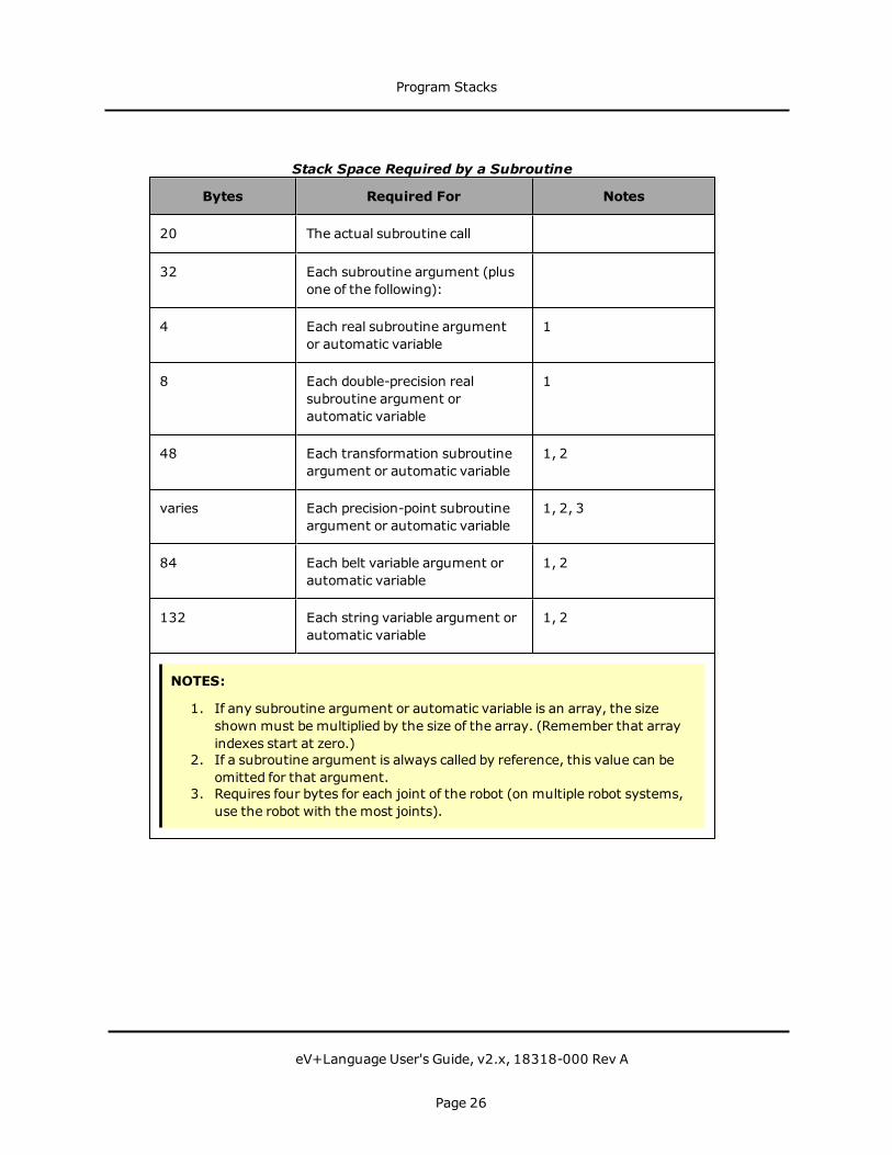
Bytes Required For Notes
20 The actual subroutine call
32 Each subroutine argument (plusone of the following):
4 Each real subroutine argumentor automatic variable
1
8 Each double-precision realsubroutine argument orautomatic variable
1
48 Each transformation subroutineargument or automatic variable
1, 2
varies Each precision-point subroutineargument or automatic variable
1, 2, 3
84 Each belt variable argument orautomatic variable
1, 2
132 Each string variable argument orautomatic variable
1, 2
NOTES:
1. If any subroutine argument or automatic variable is an array, the sizeshown must be multiplied by the size of the array. (Remember that arrayindexes start at zero.)
2. If a subroutine argument is always called by reference, this value can beomitted for that argument.
3. Requires four bytes for each joint of the robot (on multiple robot systems,use the robot with the most joints).
Stack Space Required by a Subroutine
Program Stacks
eV+Language User's Guide, v2.x, 18318-000 Rev A
Page 26

Flow of Program ExecutionProgram instructions are normally executed sequentially from the beginning of a program toits end. This sequential flow may be changedwhen a GOTO or IF...GOTO instruction, or acontrol structure, is encountered. The CALLinstruction causes another program to beexecuted, but it does not change the sequential flow through the calling program becauseexecution of the calling program resumes where it left off when a RETURN instruction isexecuted by the CALLed program.
TheWAIT instruction suspends execution of the current program until a condition issatisfied. The WAIT.EVENT instruction suspends execution of the current program until aspecified event occurs or until a specified time elapses.
The PAUSE and HALT instructions both terminate execution of the current program. After aPAUSE, program execution can be resumedwith a PROCEEDmonitor command (see theeV+ Operating System Reference Guide for information on monitor commands). Executioncannot be resumed after a HALT.
The STOP instruction may or may not terminate program execution. If there are moreprogram execution cycles to perform, the STOP instruction causes themain program to berestarted at its first step (even if the STOP instruction occurs in a subroutine). If noexecution loops remain, STOP terminates the current program.
For more details on these instructions, see Program Interrupt Instructions on page 62.
Flow of Program Execution
eV+Language User's Guide, v2.x, 18318-000 Rev A
Page 27

SubroutinesThere are three methods of exchanging information between programs:
l global variables
l soft-signals
l program argument list
When using global variables, simply use the same variable names in the different programs.Unless used carefully, this method can make program execution unpredictable and hard todebug. It also makes it difficult to write generalized subroutines because the variable namesin the main program and subroutine must always be the same.
Soft-signals are internal program signals. These are digital software switches whose state canbe read and set by all tasks and programs (including across CPUs in multiple CPU systems).See "Soft Signals" for details.
Exchanging information through the program argument list gives you better control overchangesmade to variables. It also eliminates the requirement that the variable names in thecalling program be the same as the names in the subroutine. The following sections describeexchanging data through the program parameter list.
Argument Passing
There are two important considerations when passing an argument list from a callingprogram to a subroutine. The first is making sure the calling program passes arguments inthe way the subroutine expects to receive them (mapping). The second is determining howyou want the subroutine to be able to alter the variables (passing by value or reference).
Mapping the Argument List
An argument list is a list of variables or values separated by commas. The argument listpassed to a calling program must match the subroutine's argument list in number ofarguments and data type of each argument (see Undefined Arguments on page 31). Thevariable names do not have tomatch.
When a calling program passes an argument list to a subroutine, the subroutine does not lookat the variable names in the list but the position of the arguments in the list. The argumentlist in the CALL statement is mapped item for item to the argument list of the subroutine. It isthis mapping feature that allows you to write generalized subroutines that can be called byany number of different programs, regardless of the actual values or variable names thecalling program uses.
The following figure shows the mapping of an argument list in a CALL statement to theargument list in a subroutine. The arrows indicate that each item in the list must match inposition and data type but not necessarily in name. (The CALL statement argument list caninclude values and expressions as well as variable names.)
Subroutines
eV+Language User's Guide, v2.x, 18318-000 Rev A
Page 28
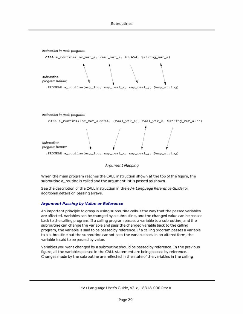
Argument Mapping
When the main program reaches the CALL instruction shown at the top of the figure, thesubroutine a_routine is called and the argument list is passed as shown.
See the description of the CALL instruction in the eV+ Language Reference Guide foradditional details on passing arrays.
Argument Passing by Value or Reference
An important principle to grasp in using subroutine calls is the way that the passed variablesare affected. Variables can be changed by a subroutine, and the changed value can be passedback to the calling program. If a calling program passes a variable to a subroutine, and thesubroutine can change the variable and pass the changed variable back to the callingprogram, the variable is said to be passed by reference. If a calling program passes a variableto a subroutine but the subroutine cannot pass the variable back in an altered form, thevariable is said to be passed by value.
Variables you want changed by a subroutine should be passed by reference. In the previousfigure, all the variables passed in the CALL statement are being passed by reference.Changesmade by the subroutine are reflected in the state of the variables in the calling
Subroutines
eV+Language User's Guide, v2.x, 18318-000 Rev A
Page 29

program. Any argument that is to be changed by a subroutine and passed back to the callingroutine must be specified as a variable (not an expression or value).
In addition to passing variables whose value you want changed, you will also pass variablesthat are required for the subroutine to perform its task but whose value you do not wantchanged after the subroutine completes execution. Pass these variables by value. When avariable is passed by value, a copy of the variable, rather than the actual variable, is passed tothe subroutine. The subroutine can make changes to the variable, but the changes are notreturned to the calling program (the variable in the calling program has the same value it hadwhen the subroutine was called).
The following figure shows how to pass the different types of variables by value. Real numbersand integers are surrounded by parentheses, :NULL is appended to location variables, and+"" is appended to string variables.
In the following figure, real_var_b is still being passed by reference, and any changesmade inthe subroutine will be reflected in the calling program. The subroutine cannot change any ofthe other variables: it can make changes only to the copies of those variables that have beenpassed to it. (It is considered poor programming practice for a subroutine to change anyarguments except those that are being passed back to the calling routine. If an inputargument must be changed, Omron Adept suggests you make an AUTOmatic copy of theargument andwork with the copy.)
Subroutines
eV+Language User's Guide, v2.x, 18318-000 Rev A
Page 30

Call by Value
Values, as well as variables, can be passed by a CALL statement. The instruction:
CALL a_routine(loc_1, 17.5, 121, "some string")
is an acceptable call to a_routine.
Undefined Arguments
If the calling program omits an argument, either by leaving a blank in the argument list(e.g., arg_1, , arg_3) or by omitting arguments at the end of a list (e.g., arg_1, arg_2), theargument are passed as undefined. The subroutine receiving the argument list can test forthis value using the DEFINED function and take appropriate action.
Program Files
Since linking and compiling are not required by eV+,main programs and subroutines alwaysexist as separate programs. The eV+ file structure allows you to keep amain program and allthe subroutines it CALLs or EXECUTEs together in a single file so that when amain programis loaded, all the subroutines it calls are also loaded. (If a program calls a subroutine that isnot resident in system memory, the error *Undefined program or variable name* willresult.)
See the descriptions of the STORE_ commands and the MODULE command in the eV+Operating System User's Guide for details. For an example of creating a program file, see"Sample Editing Session" on page 85.
Reentrant Programs
The eV+ system allows the same program to be executed concurrently by multiple programtasks. That is, the program can be reentered while it is already executing.
This allows different tasks that are running concurrently to use the same general-purposesubroutine.
Tomake a program reentrant, you must observe a few general guidelines when writing theprogram:
l Global variables can be read but must not be modified.
l Local variables should not be used.
l Only automatic variables and subroutine arguments can be modified.
In special situations, local variables can be used, and global variables can be modified, butthen the program must explicitly provide program logic to interlock access to these variables.The TAS real-valued function (defined in Table 6-4, "System Control Functions")may behelpful in these situations. (See the eV+ Language Reference Guide for details.)
Subroutines
eV+Language User's Guide, v2.x, 18318-000 Rev A
Page 31

Recursive Programs
Recursive programs are subroutines that call themselves, either directly or indirectly. A directcall occurs when a program actually calls itself, which is useful for some special programmingsituations. Indirect calls are more common. They occur when program A calls program B,which eventually leads to another call to program A before program B returns. For example,an output routine may detect an error and call an error-handling routine, which in turn callsthe original output routine to report the error.
If recursive subroutine calls are used, the program must observe the same guidelines as forreentrant programs (see Reentrant Programs on page 31). In addition, you must guaranteethat the recursive calls do not continue indefinitely. Otherwise, the program task will run outof stack space.
Asynchronous Processing
A particularly powerful feature of eV+ is the ability to respond to an event (such as anexternal signal or error condition) when it occurs, without the programmer's having toinclude instructions to test repeatedly for the event. If event handling is properly enabled,eV+ will react to an event by invoking a specified program just as if a CALL instruction hadbeen executed. Such a program is said to be called asynchronously, since its execution is notsynchronized with the normal program flow.
Asynchronous processing is enabled by the REACT, REACTE, and REACTI programinstructions. Each program task can use these instructions to prepare for independentprocessing of events. In addition, the optional eV+ Extensions software uses the WINDOWinstruction to enable asynchronous processing of window violations when the robot istracking a conveyor belt.
Sometimes a reaction must be delayed until a critical program section has completed. Also,since some events are more important than others, a program should be able to react tosome events but not others. eV+ allows the relative importance of a reaction to be specifiedby a program priority value from 1 to 127. The higher the program priority setting, the moreimportant is the reaction.
A reaction subroutine is called only if the main program priority is less than that of thereaction program priority. If the main program priority is greater than or equal to the reactionprogram priority, execution of the reaction subroutine is deferred until the main programpriority drops. Since the main program (for example, the robot control program) normallyruns at program priority zero and the minimum reaction program priority is one, any reactioncan normally interrupt the main program.
The main program priority can be raised or loweredwith the LOCK program instruction, andits current value can be determinedwith the PRIORITY real-valued function. When the mainprogram priority is raised to a certain value, all reactions of equal or lower priority are lockedout.
When a reaction subroutine is called, the main program priority is automatically set to thereaction program priority, thus preventing any reactions of equal or lower program priority
Subroutines
eV+Language User's Guide, v2.x, 18318-000 Rev A
Page 32

from interrupting it. When a RETURN instruction is executed in the reaction program, themain program priority is automatically reset to the level it had before the reaction subroutinewas called.
For further information on reactions and program priority, see the following keywords: LOCK,PRIORITY, REACT, and REACTI in the eV+ Language Reference Guide.
Error Trapping
Normally, when an error occurs during execution of a program, the program is terminatedand an error message is displayed on the system terminal. However, if the REACTEinstruction has been used to enable an error-trapping program, the eV+ system invokes thatprogram as a subroutine instead of terminating the program that encountered the error.(Each program task can have its own error trap enabled.)
Before invoking the error-trapping subroutine, eV+ locks out all other reactions by raisingthe main program priority to 254 (see Asynchronous Processing on page 32). See thedescription of the REACTE instruction in the eV+ Language Reference Guide for furtherinformation on error trapping.
Subroutines
eV+Language User's Guide, v2.x, 18318-000 Rev A
Page 33

The SEE Editor and DebuggerBeginning with eV+ version v2.x, eV+ programs are created (and debugged) through theACE user interface. The eV+ Editor and Debugger tools provide a full-featured environmentfor creating, editing and debugging eV+ programs. For more details, see the chapterProgramming ACE in the ACE User's Guide.
The SEE Editor and Debugger
eV+Language User's Guide, v2.x, 18318-000 Rev A
Page 35


Data Types and OperatorsThe following topics are described in this chapter:
Introduction 39String Data Type 40Real and Integer Data Types 42Location Data Types 44Arrays 45Variable Classes 47Operators 51String Operator 55Order of Evaluation 56
Data Types and Operators
eV+Language User's Guide, v2.x, 18318-000 Rev A
Page 37

Data Types and Operators
eV+Language User's Guide, v2.x, 18318-000 Rev A
Page 38
IntroductionThis chapter describes the data typeseV+ used by eV+.
Dynamic Data Typing and Allocation
eV+ does not require you to declare variables or their data types. The first use of a variabledetermines its data type and allocates spaeV+ce for that variable. You can create variablesand assign them a type as needed. The program instruction:
real_var = 13.65
creates the variable real_var as a real variable and assigns it the value 13.65 (if the real_varhad already been created, the instruction will merely change its value).
Numeric, string, and transformation arrays up to three dimensions can be declareddynamically.
Variable Name Requirements
The requirements for a valid variable name are:
1. Keywords reserved by Omron Adept cannot be used. The eV+ Language ReferenceGuide lists the basic keywords reserved by Omron Adept. If you have ACE Sight, TheACE Sight Reference Guide lists the additional reservedwords used by the visionsystem.
2. The first character of a variable namemust be a letter.
3. Allowable characters after the first character are letters, numbers, periods, and theunderline character.
4. Only the first 15 characters in a variable name are significant.
The following are all valid variable names:
xcountdist.to.part.33ref_frame
The following names are invalid for the reasons indicated:
3x (first character not a letter)one&two (& is an invalid name character)pi (reserved word)this_is_a_long_name (too many characters)
All but the last of these invalid names are rejected by eV+ with an error message. The extra-long name is truncated (without warning) to:
this_is_a_long_.
Introduction
eV+Language User's Guide, v2.x, 18318-000 Rev A
Page 39

String Data TypeVariable names are precededwith a dollar ($) sign to indicate that they contain string data.1The program instruction:
$string_name = "Omron Adept eV+"
allocates the string variable string_name (if it had not previously been allocated) and assignsit the value Omron Adept eV+. Numbers can be used as strings with a program instructionsuch as:
$numeric_string = "13.5"
where numeric _string is assigned the value 13.5. The program instruction:
$numeric_string = 13.5
results in an error since you are attempting to assign a real value to a string variable.
The following restrictions apply to string constants (e.g., "a string"):
l ASCII values 32 (space) to 126 (7e) are acceptable
l ASCII 34 (") cannot be used in a string
Strings can contain from 0 to 128 characters. String variables can contain values from 0 to255. For the interpretation of the full character set, see the section Character Sets on page223.
The following are all valid names for string variables:
$x $process $prototype.names $part_1
The following names are invalid for strings for the reasons indicated:
$3x (first character not a letter)$one-two (- is an invalid name character)factor ($ prefix missing)$this_is_a_long_name (too many characters)
All but the last of these invalid names are rejected by eV+ with an error message. The extralong name is truncated (without warning) to $this_is_a_long_.
ASCII Values
An ASCII value is the numeric representation of a single ASCII character. (For a complete listof the ASCII character set, see the section Character Sets on page 223.) An ASCII value isspecified by prefixing a character with an apostrophe ('). Any ASCII character from the spacecharacter (decimal value 32) to the tilde character (7e, decimal value 126) can be used as anASCII constant. Thus, the following are valid ASCII constants:
'A '1 'v '%
String Data Type
eV+Language User's Guide, v2.x, 18318-000 Rev A
Page 40

Note that the ASCII value '1 (decimal value 49) is not the same as the integer value 1(decimal value 1.0). Also, it is not the same as the string value "1".
Functions That Operate on String Data
For a summary of eV+ functions that operate on string data, see the section String-RelatedFunctions on page 82.
1The dollar sign is not considered in the character count of the variable name.
String Data Type
eV+Language User's Guide, v2.x, 18318-000 Rev A
Page 41
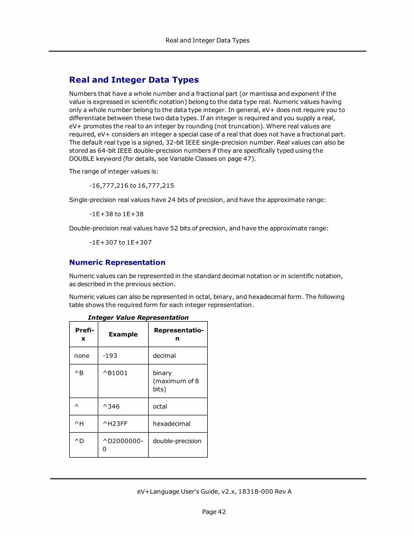
Real and Integer Data TypesNumbers that have a whole number and a fractional part (or mantissa and exponent if thevalue is expressed in scientific notation) belong to the data type real. Numeric values havingonly a whole number belong to the data type integer. In general, eV+ does not require you todifferentiate between these two data types. If an integer is required and you supply a real,eV+ promotes the real to an integer by rounding (not truncation). Where real values arerequired, eV+ considers an integer a special case of a real that does not have a fractional part.The default real type is a signed, 32-bit IEEE single-precision number. Real values can also bestored as 64-bit IEEE double-precision numbers if they are specifically typed using theDOUBLE keyword (for details, see Variable Classes on page 47).
The range of integer values is:
-16,777,216 to 16,777,215
Single-precision real values have 24 bits of precision, and have the approximate range:
-1E+38 to 1E+38
Double-precision real values have 52 bits of precision, and have the approximate range:
-1E+307 to 1E+307
Numeric Representation
Numeric values can be represented in the standard decimal notation or in scientific notation,as described in the previous section.
Numeric values can also be represented in octal, binary, and hexadecimal form. The followingtable shows the required form for each integer representation.
Prefi-x Example Representatio-
n
none -193 decimal
^B ^B1001 binary(maximum of 8bits)
^ ^346 octal
^H ^H23FF hexadecimal
^D ^D2000000-0
double-precision
Integer Value Representation
Real and Integer Data Types
eV+Language User's Guide, v2.x, 18318-000 Rev A
Page 42

Numeric Expressions
In almost all situations where a numeric value of a variable can be used, a numericexpression can also be used. The following examples all result in x having the same value.
x = 3x = 6/2x = SQRT(9)x = SQR(2) - 1x = 9 MOD 6
Logical Expressions
eV+ does not have a specific logical (Boolean) data type. Any numeric value, variable, orexpression can be used as a logical data type. eV+ considers 0 to be false and any other valueto be true.
Logical Constants
There are four logical constants, TRUE andON that will resolve to -1, and FALSE andOFFthat will resolve to 0. These constants can be used anywhere that a Boolean expression isexpected.
A logical value, variable, or expression can be used anywhere that a decision is required. Inthis example, an input signal is tested. If the signal is on (high) the variable dio.sample isgiven the value true, and the IF clause executes. Otherwise, the ELSE clause executes:
dio.sample = SIG(1001)IF dio.sample THEN
; Steps to take when signal is on (high)ELSE
; Steps to take when signal is off (low)END
Since a logical expression can be used in place of a logical variable, the first two lines of thisexample could be combined to
IF SIG(1001) THEN
Functions That Operate on Numeric Data
For a summary of eV+ functions that operate on numeric data, see the section NumericValue Functions on page 85.
Real and Integer Data Types
eV+Language User's Guide, v2.x, 18318-000 Rev A
Page 43

Location Data TypesThis section gives a brief explanation of location data. Motion Control Operations on page 99covers locations and their use in detail.
Transformations
A data type particular to eV+ is the transformation data type. This data type is a collection ofseveral values that uniquely identify a location in Cartesian space.
The creation andmodification of location variables are discussed in Motion Control Operationson page 99.
Precision Points
Precision points are a second data type particular to eV+. A precision point is a collection ofjoint angles and translational values that uniquely identify the position and orientation of arobot. The difference between transformation variables and precision-point variables willbecomemore apparent when robot motion instructions are discussed in Motion ControlOperations on page 99.
Location Data Types
eV+Language User's Guide, v2.x, 18318-000 Rev A
Page 44
ArrayseV+ supports arrays of up to three dimensions. Any eV+ data type can be stored in an array.Like simple variables, array allocation (and typing) is dynamic. Unless they are declared to beAUTOmatic, array sizes do not have to be declared.
For example:
array.one[2] = 36
allocates space for a one-dimensional array named array.one and places the value 36 inelement two of the array. (The numbers inside the brackets ([ ]) are referred to as indices.An array index can also be a variable or an expression.)
$array.two[4,5] = "row 4, col 5"
allocates space for a two-dimensional array named array.two and places row 4, col 5 in rowfour, column five of the array.
array.three[2,2,4] = 10.5
allocates space for a three-dimensional array named array.three and places the value 10.5 inrow two, column two, range four.
If any of the above instructions were executed and the array had already been declared, theinstruction wouldmerely place the value in the appropriate location. If a data type differentfrom the one the array was originally created with is specified, an error will result.
Arrays are allocated in blocks of 16. Thus, the instruction:
any_array[2] = 50
results in allocation of array elements 0 - 15. The instructions:
any_array[2] = 50any_array[20] = 75
results in the allocation of array elements 0 - 31.
Array allocation is most efficient when the highest range index exceeds the highest columnindex, and the highest column index exceeds the highest row index. (Row is the firstelement, column is the second element, and range is the third element.)
Global Array Access Restriction
eV+ has a feature where global and LOCAL arrays are automatically extended as they areused. For efficiency, there is no interlocking of the array extension process between multipletasks. A crash can occur if one task is extending or deleting an array while another is tryingto access it. The AIM software application has built-in protection to prevent this problem andthe resulting crash. However, custom eV+ programsmust be coded to avoid this problemusing one of the followingmethods:
Arrays
eV+Language User's Guide, v2.x, 18318-000 Rev A
Page 45
Method 1
If there is a known reasonable upper-bound on the array dimensions, define (by assigning anarbitrary value to it) the highest element of the array. For multi-dimensional arrays, assignthe highest element of each possible sub-array. This assignment prevents the arrays fromextending.
Method 2
Use the TAS function to interlock access to the array. In this case, access to the array ishandled exclusively from one or two subroutines that include the TAS to control access to thearray. For details, see the TAS program instruction in the eV+ Language Reference Guide.
Arrays
eV+Language User's Guide, v2.x, 18318-000 Rev A
Page 46

Variable ClassesIn addition to having a data type, variables belong to one of three classes, GLOBAL, LOCAL,or AUTOMATIC. These classes determine how a variable can be altered by different callinginstances of a program.
Global Variables
This is the default class. Unless a variable has been specifically declared to be LOCAL or AUTO,a newly created variable is considered global. Once a global variable has been initialized, it isavailable to any executing program1 until the variable is deleted or all programs thatreference it are removed from system memory (with a DELETE or ZERO instruction). Globalvariables can be explicitly declared with the GLOBAL program instruction.
GLOBAL DOUBLE dbl_real_var
Global variables are very powerful and should be used carefully and consciously. If youcannot think of a good reason tomake a variable global, good programming practice dictatesthat you declare it to be LOCAL or AUTO.
Local Variables
Local variables are created by a program instruction similar to:
LOCAL the_local_var
where the variable the_local_var is created as a local variable. Local variables can be changedonly by the program in which they are declared.
An important difference between local variables in eV+ and local variables in most otherhigh-level languages is that eV+ local variables are local to all copies (calling instances) of aprogram, not just a particular calling instance of that program. This distinction is critical ifyou write recursive programs. In recursive programs you will generally want to use the nextvariable class, AUTO.
Automatic Variables
Automatic variables are created by a program instruction similar to:
AUTO the_auto_var
where the_auto_var is created as an automatic variable. Automatic variables can bechanged only by a particular calling instance of a program.
AUTO statements cannot be added or deleted when the program is on the stack. See "SpecialEditing Situations."
AUTO DOUBLE dbl_auto_var
Variable Classes
eV+Language User's Guide, v2.x, 18318-000 Rev A
Page 47

Automatic variables are more like the local variables of other high-level languages. If you arewriting programs using a recursive algorithm, you will most likely want to use variables in theautomatic class.
Scope of Variables
The scope of a variable refers to the range of programs that can see that variable. Thefollowing figureshows the scope of the different variable classes. A variable can be altered bythe program(s) indicated in the shaded area of the box it is in plus any programs that are insmaller boxes. When a program declares an AUTO or LOCAL variable, any GLOBAL variables ofthe same name created in other programs are not accessible.
Variable Scoping
Variable Scope Example shows an example of using the various variable classes. Notice that:
l prog_1 declares a to be GLOBAL. Thus, it is available to all programs not having anAUTO or LOCAL a.
l prog_2 creates an undeclared variable b. By default, b is GLOBAL and available to other
Variable Classes
eV+Language User's Guide, v2.x, 18318-000 Rev A
Page 48

programs not having a LOCAL or AUTO b.
l prog_3 declares an AUTO a and cannot use GLOBAL a. After prog_3 completes, thevalue of AUTO a is deleted.
l prog_4 declares a LOCAL a and, therefore, cannot use GLOBAL a. Unlike the AUTO a inprog_3, however, the value of LOCAL a is stored and is available for any future CALLsto prog_4.
Variable Scope Example
Variable Classes
eV+Language User's Guide, v2.x, 18318-000 Rev A
Page 49
Variable Initialization
Before a variable can be used it must be initialized. String and numeric variables can beinitialized by placing them on the left side of an assignment statement. The statements:
var_one = 36$var_two = "two"
initializes the variables var_one and $var_two.
var_one = var_two
initializes var_one if var_two has already been initialized. Otherwise, an undefined valueerror is returned. A variable can never be initialized on the right side of an assignmentstatement (var_two could never be initialized by the above statement).
The statement:
var_one = var_one + 10
is valid only if var_one has been initialized in a previous statement.
Strings, numeric variables, and location variables can be initialized by being loaded from a diskfile.
Strings and numeric variables can be initialized with the PROMPT instruction.
Transformations and precision points can be initialized with the SET or HERE programinstructions. They can also be initialized with the HERE monitor command or with the T20pendant. See the eV+ Operating System Reference Guide for information on monitorcommands.
1Unless the program has declared a LOCAL or AUTO variable with the same name.
Variable Classes
eV+Language User's Guide, v2.x, 18318-000 Rev A
Page 50

OperatorsThe following sections discuss the valid operators.
Assignment Operator
The equal sign (=) is used to assign a value to a numeric or string variable. The variable beingassigned a value must appear by itself on the left side of the equal sign. The right side of theequal sign can contain any variable or value of the same data type as the left side, or anyexpression that resolves to the same data type as the left side. Any variables used on theright side of an assignment operator must have been previously initialized.
Location variables require the use of the SET instruction for a valid assignment statement.The instruction:
loc_var1 = loc_var2
is unacceptable for location and precision-point variables.
Mathematical Operators
eV+ uses the standardmathematical operators shown in the following table.
Symbol Function
+ addition
- subtraction or unary minus
* multiplication
/ division
MOD modular (remainder) division
Mathematical Operators
Relational OperatorsRelational operators are used in expressions that yield a Boolean value. The resolution of anexpression containing a relational operator is always -1 (true) or 0 (false) and tells you if thespecific relation stated in the expression is true or false. The most common use of relationalexpressions is with the control structures.
eV+ uses the standard relational operators shown in the following table.
Operators
eV+Language User's Guide, v2.x, 18318-000 Rev A
Page 51

Symbol Function
== equal to
< less than
> greater than
<= or =< less than or equal to
>= or => greater than or equal to
<> not equal to
Relational Operators
If x has a value of 6 and y has a value of 10, the following Boolean expressions resolve to -1(true):
x < yy >= xy <> x
and these expressions resolve to 0 (false):
x > yx <> 6x == y
Note the difference between the assignment operator = and the relational operator ==:
z = x == y
In this example, z is assigned a value of 0 since the Boolean expression x == y is false andwould therefore resolve to 0. A relational operator never changes the value of the variableson either side of the relational operator.
Logical Operators
Logical operators affect the resolution of a Boolean variable or expression, and combineseveral Boolean expressions so they resolve to a single Boolean value.
eV+ uses the standard logical operators shown in the following table.
Symbol Effect
NOT Complement the expression
Logical Operators
Operators
eV+Language User's Guide, v2.x, 18318-000 Rev A
Page 52
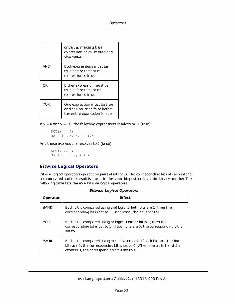
or value;makes a trueexpression or value false andvice versa.
AND Both expressions must betrue before the entireexpression is true.
OR Either expression must betrue before the entireexpression is true.
XOR One expression must be trueand one must be false beforethe entire expression is true.
If x = 6 and y = 10, the following expressions resolves to -1 (true):
NOT(x == 7)(x > 2) AND (y =< 10)
And these expressions resolves to 0 (false):
NOT(x == 6)(x < 2) OR (y > 10)
Bitwise Logical Operators
Bitwise logical operators operate on pairs of integers. The corresponding bits of each integerare compared and the result is stored in the same bit position in a third binary number.Thefollowing table lists the eV+ bitwise logical operators.
Operator Effect
BAND Each bit is compared using and logic. If both bits are 1, then thecorresponding bit is set to 1. Otherwise, the bit is set to 0.
BOR Each bit is compared using or logic. If either bit is 1, then thecorresponding bit is set to 1. If both bits are 0, the corresponding bit isset to 0.
BXOR Each bit is compared using exclusive or logic. If both bits are 1 or bothbits are 0, the corresponding bit is set to 0. When one bit is 1 and theother is 0, the corresponding bit is set to 1.
Bitwise Logical Operators
Operators
eV+Language User's Guide, v2.x, 18318-000 Rev A
Page 53
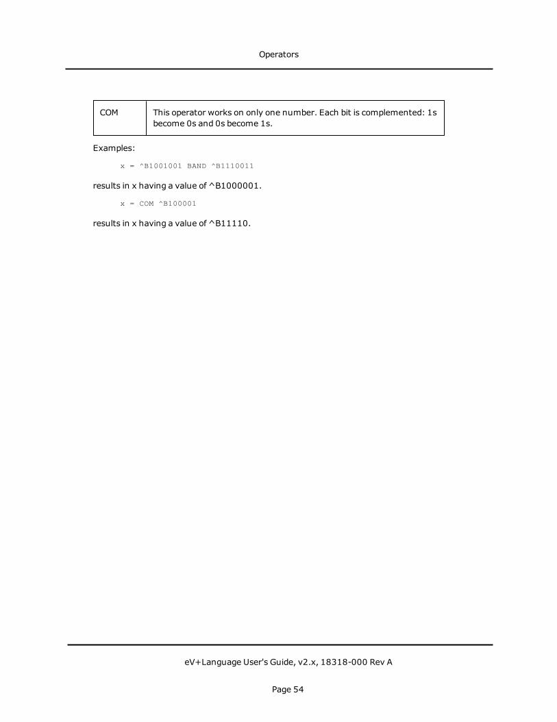
COM This operator works on only one number. Each bit is complemented: 1sbecome 0s and 0s become 1s.
Examples:
x = ^B1001001 BAND ^B1110011
results in x having a value of ^B1000001.
x = COM ^B100001
results in x having a value of ^B11110.
Operators
eV+Language User's Guide, v2.x, 18318-000 Rev A
Page 54
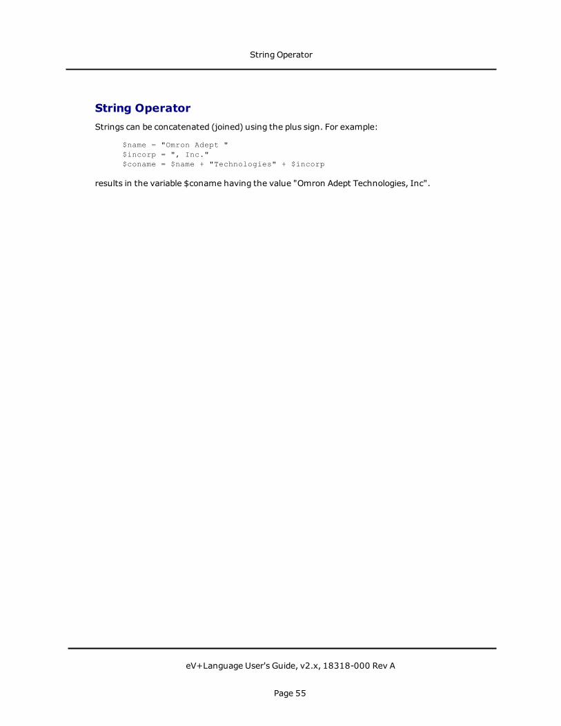
String OperatorStrings can be concatenated (joined) using the plus sign. For example:
$name = "Omron Adept "$incorp = ", Inc."$coname = $name + "Technologies" + $incorp
results in the variable $coname having the value "Omron Adept Technologies, Inc".
String Operator
eV+Language User's Guide, v2.x, 18318-000 Rev A
Page 55

Order of EvaluationExpressions containingmore than one operator are not evaluated in a simple left to rightmanner. The following table lists the order in which operators are evaluated. Within anexpression, functions are evaluated first, with expressions within the function evaluatedaccording to the table.
The order of evaluation can be changed using parentheses. Operators within each pair ofparentheses, starting with the most deeply nested pair, are completely evaluated accordingto the rules in the following table before any operators outside the parentheses areevaluated.
Operators on the same level in the table are evaluated strictly left to right.
Operator
NOT, COM
- (Unary minus)
*, /, MOD, AND, BAND
+, -, OR, BOR, XOR, BXOR
==, <=, >=, <, >, <>
Order of Operator Evaluation
Order of Evaluation
eV+Language User's Guide, v2.x, 18318-000 Rev A
Page 56
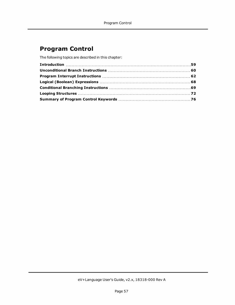
Program ControlThe following topics are described in this chapter:
Introduction 59Unconditional Branch Instructions 60Program Interrupt Instructions 62Logical (Boolean) Expressions 68Conditional Branching Instructions 69Looping Structures 72Summary of Program Control Keywords 76
Program Control
eV+Language User's Guide, v2.x, 18318-000 Rev A
Page 57

Program Control
eV+Language User's Guide, v2.x, 18318-000 Rev A
Page 58

IntroductionThis chapter introduces the structures available in eV+ to control program execution. Thesestructures include the looping and branching instructions common tomost high-levellanguages as well as some instructions specific to eV+.
Introduction
eV+Language User's Guide, v2.x, 18318-000 Rev A
Page 59

Unconditional Branch InstructionsThere are three unconditional branching instructions in eV+:
l GOTO
l CALL
l CALLS
GOTO
The GOTO instruction causes program execution to branch immediately to a program labelinstruction somewhere else in the program. The syntax for GOTO is:
GOTO label
label is an integer entered at the beginning of a line of program code. label isnot the same as the program step numbers: Step numbers are assignedby the system; labels are entered by the programmer as the opening to aline of code. In the next code example, the numbers in the first columnare program step numbers. The numbers in the second column areprogram labels.
61 .62 GOTO 10063 .64 .65 100 TYPE "The instruction GOTO 100 got me he re."66 .
A GOTO instruction can branch to a label before or after the GOTO instruction.
GOTO instructions can make program logic difficult to follow and debug, especially in a long,complicated program with many subroutine calls. Use GOTO instructions with care. Acommon use of GOTO is as an exit routine or exit on error instruction.
CALL
The CALL and CALLS instructions are used in eV+ to implement subroutine calls. The CALLinstruction causes program execution to be suspended and execution of a new program tobegin. When the new program has completed execution, execution of the original programresumes at the instruction after the CALL instruction. The details of subroutine creation,execution, and parameter passing are covered in Subroutines on page 28. The simplifiedsyntax for a CALL instruction is:
CALL program(arg_list)
program is the name of the program to be called. The program namemust bespecified exactly, and the program being CALLedmust be resident insystem memory.
Unconditional Branch Instructions
eV+Language User's Guide, v2.x, 18318-000 Rev A
Page 60
arg_list is the list of arguments being passed to the subroutine. These argumentscan be passed either by value or by reference andmust agree with thearguments expected by the program being called. Subroutines andargument lists are described in "Subroutines."
The code:
48 .49 CALL check_data(locx, locy, length)50 .
suspends execution of the calling program, passes the arguments locx, locy, and length toprogram check_data, executes check_data, and (after check_data has completed execution)resumes execution of the calling program at step 50.
CALLS
The CALLS instruction is identical to the CALL instruction except for the specification ofprogram. For a CALLS instruction, program is a string value, variable, or expression. Thisallows you to call different subroutines under different conditions using the same line ofcode. (These different subroutines must have the same arg_list.) You can use this techniqueto create "virtual functions" in object oriented languages like C++, C#, Java or Python.
The code:
47 .48 $program_name = $program_list[program_select]49 CALLS $program_name(length, width)50 .
suspends execution of the calling program, passes the parameters length andwidth to theprogram specified by array index program_select from the array $program_list, executes thespecified program, and resume execution of the calling program at step 50.
Unconditional Branch Instructions
eV+Language User's Guide, v2.x, 18318-000 Rev A
Page 61

Program Interrupt InstructionseV+ provides several ways of suspending or terminating program execution. A program canbe put on hold until a specific condition becomes TRUE using the WAIT instruction. A programcan be put on hold for a specified time period or until an event is generated in another task bythe WAIT.EVENT instruction. A program can be interrupted based on a state transition of adigital input signal with the REACT and REACTI instructions. Program errors can beintercepted and handled with a REACTE instruction. Program execution can be terminatedwith the HALT, STOP, and PAUSE commands. These instructions interrupt the program inwhich they are contained. Any programs running as other tasks are not affected. Robotmotion can be controlled with the BRAKE, BREAK, and DELAY instructions. (The ABORT andPROCEEDmonitor commands can also be used to suspend and proceed programs, see theeV+ Operating System Reference Guide for details.)
WAIT
WAIT suspends program execution until a condition (or conditions) becomes true.
WAIT SIG(1032, -1028)
delays execution until digital input signal 1032 is on and 1028 is off.
WAIT TIMER(1) > 10
suspends execution until timer 1 returns a value greater than 10.
WAIT.EVENT
The instruction:
WAIT.EVENT , 3.7
suspends execution for 3.7 seconds. This wait is more efficient than waiting for a timer (as inthe previous example) because the task does not have to loop continually to check the timervalue.
The instruction:
WAIT.EVENT
suspends execution until another task issues a SET.EVENT instruction to the waiting task. Ifthe SET.EVENT does not occur, the task waits indefinitely. For more details on SET.EVENT,see the eV+ Language Reference Guide.
REACT and REACTI
When a REACT or REACTI instruction is encountered, the program begins monitoring a digitalinput signal specified in the REACT instruction. This signal is monitored in the backgroundwith program execution continuing normally until the specified signal transitions. When (and
Program Interrupt Instructions
eV+Language User's Guide, v2.x, 18318-000 Rev A
Page 62
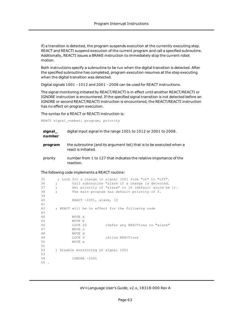
if) a transition is detected, the program suspends execution at the currently executing step.REACT and REACTI suspend execution of the current program and call a specified subroutine.Additionally, REACTI issues a BRAKE instruction to immediately stop the current robotmotion.
Both instructions specify a subroutine to be run when the digital transition is detected. Afterthe specified subroutine has completed, program execution resumes at the step executingwhen the digital transition was detected.
Digital signals 1001 - 1012 and 2001 - 2008 can be used for REACT instructions.
The signal monitoring initiated by REACT/REACTI is in effect until another REACT/REACTI orIGNORE instruction is encountered. If the specified signal transition is not detected before anIGNORE or second REACT/REACTI instruction is encountered, the REACT/REACTI instructionhas no effect on program execution.
The syntax for a REACT or REACTI instruction is:
REACT signal_number, program, priority
signal_number
digital input signal in the range 1001 to 1012 or 2001 to 2008.
program the subroutine (and its argument list) that is to be executed when areact is initiated.
priority number from 1 to 127 that indicates the relative importance of thereaction.
The following code implements a REACT routine:
35 ; Look for a change in signal 1001 from "on" to "off".36 ; Call subroutine "alarm if a change is detected.37 ; Set priority of "alarm" to 10 (default would be 1).38 ; The main program has default priority of 0.3940 REACT -1001, alarm, 104142 ; REACT will be in effect for the following code4344 MOVE a45 MOVE b46 LOCK 20 ;Defer any REACTions to "alarm"47 MOVE c48 MOVE d49 LOCK 0 ;Allow REACTions50 MOVE e5152 ; Disable monitoring of signal 10015354 IGNORE -100155 .
Program Interrupt Instructions
eV+Language User's Guide, v2.x, 18318-000 Rev A
Page 63

If signal 1001 transitions during execution of step 43, step 43 completes, the subroutinealarm is called, and execution resumes at step 44.
If signal 1001 transitions during execution of step 47, steps 47, 48, and 49 completes (sincethe program had been given a higher priority than REACT), the subroutine alarm is called,and execution resumes at step 50.1
REACTE
REACTE enables a reaction program that is run whenever a system error that causesprogram execution to terminate is encountered. This includes all robot errors, hardwareerrors, andmost system errors (it does NOT include I/O errors).
Unlike REACT and REACTI, REACTE cannot be deferred based on priority considerations. Theinstruction:
REACTE trouble
enables monitoring of system errors and execute the program trouble whenever a systemerror is generated.
HALT, STOP, and PAUSE
When a HALT instruction is encountered, program execution is terminated, and any openserial or disk units are DETACHED and FCLOSEd. PROCEED or RETRY will not resumeexecution.
When a STOP instruction is encountered, execution of the current program cycle isterminated and the next execution cycle resumes at the first step of the program. If the STOPinstruction is encountered on the last execution cycle, program execution is terminated, andany open serial or disk units are DETACHED and FCLOSEd. PROCEED or RETRY will notresume execution. (See EXECUTE for details on execution cycles.)When a PAUSE instructionis encountered, execution is suspended. After a PAUSE, the system prompt appears andMonitor Commands can be executed. This allows you to verify the values of program variablesand set system parameters. This is useful during program debugging. The monitor commandPROCEED resumes execution of a program interrupted with the PAUSE command.
BRAKE, BREAK, and DELAY
BRAKE aborts the current robot motion. This instruction can be issued from any task.Program execution is not suspended and the program (executing as task 0) continues toexecute at the next instruction. BREAK suspends program execution (defeats forwardprocessing) until the current robot motion is completed. This instruction can be executed onlyfrom a robot control program and is usedwhen completion of the current robot motion mustoccur before execution of the next instruction. A DELAY instruction specifies the minimumdelay between robot motions (not program instructions).
Program Interrupt Instructions
eV+Language User's Guide, v2.x, 18318-000 Rev A
Page 64
Additional Program Interrupt Instructions
You can specify a parameter in the instruction line for the I/O instructions ATTACH, READ,GETC, andWRITE that causes the program to suspend until the I/O request has beensuccessfully completed.
Program Interrupt Example
The following figure shows how the task and program priority scheme works. It also showshow the asynchronous and program interrupt instructions work within the priority scheme.The example makes the following assumptions:
l Task 1 runs in all time slices at priority 30
l Task 2 runs in all time slices at priority 20
l All system tasks are ignored
l All system interrupts are ignored
The illustration shows the time lines of executing programs. A solid line indicates a programis running, and a dotted line indicates a program is waiting. The Y axis shows the programpriority. The X axis is divided into 16-millisecondmajor cycles. The example shows two tasksexecuting concurrently with REACT routines enabled for each task. Note how the LOCKinstructions and triggering of the REACT routines change the program priority.
The sequence of events for the example is:
1. Task 1 is running program prog_a at program priority 0. A reaction program based onsignal 1003 is enabled at priority 5.
2. Signal 1003 is asserted externally. The signal transition is not detected until the nextmajor cycle.
3. The signal 1003 transition is detected. The task 1 reaction program begins execution,interrupting prog_a.
4. The task 1 reaction program reenables itself and completes by issuing a RETURNinstruction. prog_a resumes execution in task 1.
5. Task 1 prog_a issues a CLEAR.EVENT instruction followed by aWAIT.EVENTinstruction to wait for its event flag to be set. Task 1 is suspended, and task 2 resumesexecution of prog_b. Task 2 has a reaction program based on signal 1010 enabled atpriority 5.
6. Task 2 prog_b issues a LOCK 10 instruction to raise its program priority to level 10.
7. Signal 1010 is asserted externally. The signal transition is not detected until the nextmajor cycle.
8. The signal 1010 transition is detected, and the task 2 reaction is triggered. However,
Program Interrupt Instructions
eV+Language User's Guide, v2.x, 18318-000 Rev A
Page 65
since the reaction is at level 5 and the current program priority is 10, the reactionexecution is deferred.
9. Task 2 prog_b issues a LOCK 0 instruction to lower its program priority to level 0. Sincea level 5 reaction program is pending, it begins execution immediately and sets theprogram priority to 5.
10. Signal 1003 is asserted externally. The signal transition is not detected until the nextmajor cycle.
11. The signal 1003 transition is detected which triggers the task 1 reaction routine andalso sets the task 1 event flag. Since task 1 has a higher priority (30) than task 2 (20),task 1 begins executing its reaction routine and task 2 is suspended.
12. The task 1 reaction routine completes by issuing a RETURN instruction. Controlreturns to prog_a in task 1.
13. Task 1 prog_a issues a CLEAR.EVENT instruction followed by aWAIT.EVENTinstruction to wait for its event flag to be set. Task 1 is suspended and task 2 resumesexecution of its reaction routine.The task 2 reaction routine completes by issuing a RETURN instruction. Controlreturns to prog_b in task 2.
14. Task 2 prog_b issues a SET.EVENT 1 instruction, setting the event flag for task 1. Task2 now issues a RELEASE program instruction to yield control of the CPU.
15. Since the task 1 event flag is now set, and its priority is higher than task 2, task 1resumes execution, and task 2 is suspended.
Program Interrupt Instructions
eV+Language User's Guide, v2.x, 18318-000 Rev A
Page 66

Priority Example 2
1The LOCK instruction can be used to control execution of a program after a REACT orREACTI subroutine has completed.
Program Interrupt Instructions
eV+Language User's Guide, v2.x, 18318-000 Rev A
Page 67

Logical (Boolean) ExpressionsThe next two sections discuss program control structures whose execution depends on anexpression or variable that takes on a Boolean value (a variable that is either true or false, oran expression that resolves to true or false). An expression can take into account any numberof variables or digital input signals as long as the final resolution of the expression is a Booleanvalue. In eV+, any number (real or integer) can satisfy this requirement. Zero is consideredfalse; any nonzero number is considered true. There are four system constants, TRUE andONthat resolve to -1, and FALSE andOFF, that resolve to 0.
Examples of valid Boolean expressions:
y > 32NOT(y > 32)x == 56x AND y(x AND y) OR (var1 < var2)-1
For details on eV+ relational operators, see Relational Operators on page 51.
Logical (Boolean) Expressions
eV+Language User's Guide, v2.x, 18318-000 Rev A
Page 68

Conditional Branching InstructionsConditional branching instructions allow you to execute blocks of code based on the currentvalues of program variables or expressions. eV+ has three conditional branch instructions:
l IF...GOTO
l IF...THEN...ELSE
l CASE value OF
IF...GOTO
IF...GOTO behaves similarly to GOTO, but a condition can be attached to the branch. If theinstruction:
IF logical_expression GOTO 100
is encountered, the branch to label 100 occurs only if logical_expression has a value of true.
IF...THEN...ELSE
The basic conditional instruction is the IF...THEN...ELSE clause. This instruction has twoforms:
IF expression THENcode block (executed when expression is true)
END
IF expression THENcode block (executed when expression is true)
ELSEcode block (executed when expression is false)
END
expressionis any well-formed Boolean expression (described above).
In the following example, if program execution reaches step 59 and num_parts is greaterthan 75, step 60 is executed. Otherwise, execution resumes at step 62.
56 .57 ;CALL "check_num" if "num_parts" is greater than 755859 IF num_parts > 75 THEN60 CALL check_num(num_parts)61 END62 .
In the following example, if program execution reaches step 37 with input signal 1033 onand need_part true, the program executes steps 38 to 40 and resumes at step 44.Otherwise, it executes step 42 and resumes at step 44.
Conditional Branching Instructions
eV+Language User's Guide, v2.x, 18318-000 Rev A
Page 69

32 .33 ; If I/O signal 1033 is on and Boolean "need_part" is34 ; true, then pick up the part35 ; else alert the operator.3637 IF SIG(1033) AND need_part THEN38 MOVE loc139 CLOSEI40 DEPART 5041 ELSE42 TYPE "Part not picked up."43 END44 .
CASE value OF
The IF...THEN...ELSE structure allows a program to take one of two different actions. TheCASE structure will allow a program to take one of many different actions based on the valueof a variable. The variable usedmust be a real or an integer. The form of the CASE structureis:
CASE target OFVALUE list_of_values:
code block (executed when target is in list_of_values)VALUE list_of_values:
code block (executed when target is in list_of_values)...
ANYcode block (executed when target not in any list_of_values)
END
real value to match.
list_of_valueslist (separated by commas) of real values. If one of the values in the listequals target, the code following that value statement is executed.
Example5 ; Create a menu structure using a CASE statement6667 50 TYPE "1. Execute the program."68 TYPE "2. Execute the programmer."69 TYPE "3. Execute the computer."70 PROMPT "Enter menu selection.", select7172 CASE select OF73 VALUE 1:74 CALL exec_program()75 VALUE 2:76 CALL exec_programmer()77 VALUE 3:78 CALL exec_computer()79 ANY
Conditional Branching Instructions
eV+Language User's Guide, v2.x, 18318-000 Rev A
Page 70

80 PROMPT "Entry must be from 1 to 3", select81 GOTO 5082 END83 .
If the above code is rewritten without an ANY statement, and a value other than 1, 2, or 3 isentered, the program continues to execute at step 83 without executing any program.
Conditional Branching Instructions
eV+Language User's Guide, v2.x, 18318-000 Rev A
Page 71

Looping StructuresIn many cases, you will want the program to execute a block of code more than once. eV+has three looping structures that allow you to execute blocks of code a variable number oftimes. The three instructions are:
l FOR
l DO...UNTIL
l WHILE...DO
FOR
A FOR instruction creates an execution loop that will execute a given block of code a specifiednumber of times. The basic form of a FOR loop is:
FOR index = start_val TO end_val STEP incr.code block.
END
index is a real variable that keeps track of the number of times the FOR loop hasbeen executed. This variable is available for use within the loop.
start_val is a real expression for the starting value of the index.
end_val is a real expression for the ending value of the index. Execution of theloop terminates when index reaches this value.
incr is a real expression indicating the amount index is to be incrementedafter each execution of the loop. The default value is 1.
Examples88 .89 ; Output even elements of array "$names" (up to index 32)9091 FOR i = 2 TO 32 STEP 292 TYPE $names[i]93 END94 .
.102 .103 ; Output the values of the 2 dimensional array "values" in104 ; column and row form (10 rows by 10 columns)105 .106 FOR i = 1 TO 10107 FOR j = 1 to 10108 TYPE values[i,j], /S109 END
Looping Structures
eV+Language User's Guide, v2.x, 18318-000 Rev A
Page 72

110 TYPE " ", /C1111 END112 .
A FOR loop can be made to count backward by entering a negative value for the stepincrement.13 .14 ; Count backward from 10 to 11516 FOR i = 10 TO 1 STEP -117 TYPE i18 END19 .
Changing the value of index inside a FOR loopwill cause the loop to behave improperly. Toavoid problems with the index, make the index variable an auto variable and do not changethe index from inside the FOR loop. Changes to the starting and ending variables do notaffect the FOR loop once it is executing.
DO...UNTIL
DO...UNTIL is a looping structure that executes a given block of code an indeterminatenumber of times. Termination of the loop occurs when the Boolean expression or variablethat controls the loop becomes true. The Boolean is tested after each execution of the codeblock-if the expression evaluates to true, the loop is not executed again. Since theexpression is not evaluated until after the code block has been executed, the code block willalways execute at least once. The form for this looping structure is:
DO.code block.
UNTIL expression
expressionis any well-formed Boolean expression. This expressionmust eventuallyevaluate to true, or the loop executes indefinitely.
20 .21 ; Output the numbers 1 to 100 to the screen2223 x = 124 DO25 TYPE x26 x = x + 127 UNTIL x > 10028 .
Step 26 ensures that x will reach a high enough value so that the expression x > 100becomes true.
43 .44 ; Echo up to 15 characters to the screen. Stop when 1545 ; characters or the character "#" have been entered.
Looping Structures
eV+Language User's Guide, v2.x, 18318-000 Rev A
Page 73
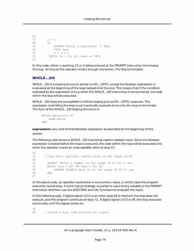
4647 x = 148 DO49 PROMPT "Enter a character: ", $ans50 TYPE $ans51 x = x + 152 UNTIL (x > 15) OR ($ans == "#")53 .
In this code, either x reaching 15 or # being entered at the PROMPT instruction terminatesthe loop. As long as the operator enters enough characters, the loop terminates.
WHILE...DO
WHILE...DO is a looping structure similar to DO...UNTIL except the Boolean expression isevaluated at the beginning of the loop instead of at the end. This means that if the conditionindicated by the expression is true when the WHILE...DO instruction is encountered, the codewithin the loopwill be executed.
WHILE...DO loops are susceptible to infinite looping just as DO...UNTIL loops are. Theexpression controlling the loopmust eventually evaluate to true for the loop to terminate.The form of the WHILE...DO looping structure is:
WHILE expression DOcode block
END
expressionis any well-formed Boolean expression as described at the beginning of thissection.
The following code shows aWHILE...DO loop being used to validate input. Since the Booleanexpression is tested before the loop is executed, the code within the loopwill be executed onlywhen the operator inputs an unacceptable value at step 23.
20 .21 ; Loop until operator inputs value in the range 32-642223 PROMPT "Enter a number in the range 32 to 64.", ans24 WHILE (ans < 32) OR (ans > 64) DO25 PROMPT "Number must be in the range 32-64.", ans26 END27 .
In the above code, an operator could enter a nonnumeric value, in which case the programexecution would stop. A more robust strategy would be to use a string variable in the PROMPTinstruction and then use the $DECODE and VAL functions to evaluate the input.
In the following code, if digital signal 1033 is on when step 69 is reached, the loop does notexecute, and the program continues at step 73. If digital signal 1033 is off, the loop executescontinually until the signal comes on.
65 .66 ; Create a busy loop waiting for signal
Looping Structures
eV+Language User's Guide, v2.x, 18318-000 Rev A
Page 74
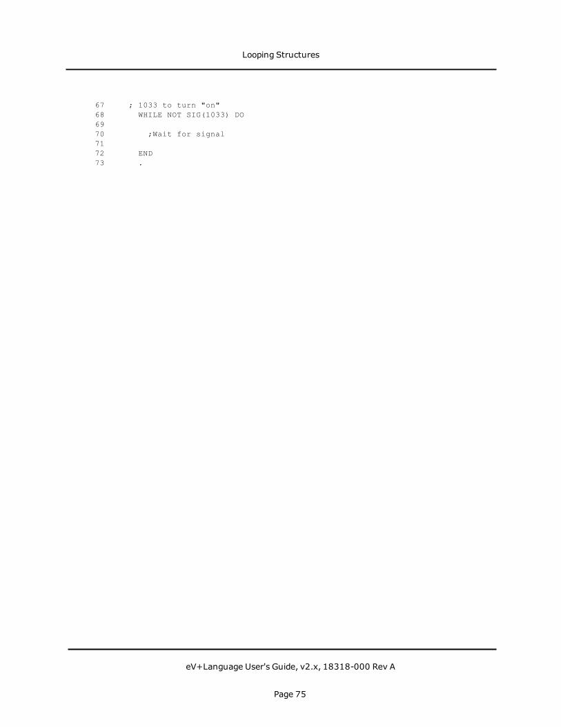
67 ; 1033 to turn "on"68 WHILE NOT SIG(1033) DO6970 ;Wait for signal7172 END73 .
Looping Structures
eV+Language User's Guide, v2.x, 18318-000 Rev A
Page 75

Summary of Program Control KeywordsThe following table summarizes the program control instructions. See the eV+ LanguageReference Guide for details on these commands.
Keyword Type Function
ABORT ProgramInstruction
Terminate execution of a control program.
CALL ProgramInstruction
Suspend execution of the current program andcontinue execution with a new program (that is, asubroutine).
CALLS ProgramInstruction
Suspend execution of the current program andcontinue execution with a new program (that is, asubroutine) specified with a string value.
CASE ProgramInstruction
Initiate processing of a CASE structure by definingthe value of interest.
CLEAR.EVENT ProgramInstruction
Clear an event associated with the specified task.
CYCLE.END ProgramInstruction
Terminate the specified control program the nexttime it executes a STOP program instruction (or itsequivalent). Suspend processing of an applicationprogram or command program until a programcompletes execution.
DO ProgramInstruction
Introduce a DO program structure.
EXECUTE ProgramInstruction
Begin execution of a control program.
EXIT ProgramInstruction
Exit a FOR, DO, or WHILE control structure.
FOR ProgramInstruction
Execute a group of program instructions a certainnumber of times.
GET.EVENT Real-Valued
Return events that are set for the specified task.
Program Control Operations
Summary of Program Control Keywords
eV+Language User's Guide, v2.x, 18318-000 Rev A
Page 76

Keyword Type Function
Function
GOTO ProgramInstruction
Perform an unconditional branch to the program stepidentified by the given label.
HALT ProgramInstruction
Stop program execution and do not allow theprogram to be resumed.
IF...GOTO ProgramInstruction
Branch to the specified label if the value of a logicalexpression is TRUE (nonzero).
IF...THEN ProgramInstruction
Conditionally execute a group of instructions (or oneof two groups) depending on the result of a logicalexpression.
LOCK ProgramInstruction
Set the program reaction lock-out priority to thevalue given.
MCS ProgramInstruction
Invoke amonitor command from a control program.
NEXT ProgramInstruction
Break a FOR, DO, or WHILE structure and start thenext iteration of the control structure.
PAUSE ProgramInstruction
Stop program execution but allow the program to beresumed.
PRIORITY Real-ValuedFunction
Return the current reaction lock-out priority for theprogram.
REACTREACTI
ProgramInstruction
Initiate continuousmonitoring of a specified digitalsignal and automatically trigger a subroutine call ifthe signal transitions properly.
REACTE ProgramInstruction
Initiate the monitoring of errors that occur duringexecution of the current program task.
RELEASE ProgramInstruction
Allow the next available program task to run.
RETURN Program Terminate execution of the current subroutine and
Summary of Program Control Keywords
eV+Language User's Guide, v2.x, 18318-000 Rev A
Page 77

Keyword Type Function
Instruction resume execution of the last-suspended program atthe step following the CALL or CALLS instruction thatcaused the subroutine to be invoked.
RETURNE ProgramInstruction
Terminate execution of an error reaction subroutineand resume execution of the last-suspendedprogram at the step following the instruction thatcaused the subroutine to be invoked.
RUNSIG ProgramInstruction
Turn on (or off) the specified digital signal as long asexecution of the invoking program task continues.
SET.EVENT ProgramInstruction
Set an event associated with the specified task.
STOP ProgramInstruction
Terminate execution of the current program cycle.
WAIT ProgramInstruction
Put the program into a wait loop until the condition isTRUE.
WAIT.EVENT ProgramInstruction
Suspend program execution until a specified eventhas occurred, or until a specified amount of time haselapsed.
WHILE ProgramInstruction
Initiate processing of a WHILE structure if thecondition is TRUE or skipping of the WHILE structureif the condition is initially FALSE.
Summary of Program Control Keywords
eV+Language User's Guide, v2.x, 18318-000 Rev A
Page 78
FunctionsThe following topics are described in this chapter:
Using Functions 81String-Related Functions 82Location, Motion, and External Encoder Functions 84Numeric Value Functions 85Logical Functions 87System Control Functions 88
Functions
eV+Language User's Guide, v2.x, 18318-000 Rev A
Page 79

Functions
eV+Language User's Guide, v2.x, 18318-000 Rev A
Page 80
Using FunctionseV+ provides you with a wide variety of predefined functions for performing string,mathematical, and general system parameter manipulation. In most cases, you mustprovide the data that is input to a function. The function then returns a value based on aspecific operation on that data. Functions can be used anywhere a value or expression wouldbe used.
Variable Assignment Using Functions
The instruction:
$curr_time = $TIME()
puts the current system time into the variable $curr_time. This is an example of a functionthat does not require any input data. The instruction:
var_root = SQRT(x)
puts the square root of the value x into var_root. X is not changed by the function.
Functions Used in Expressions
A function can be usedwherever an expression can be used (as long as the data typereturned by the function is the correct type). The instruction:
IF LEN($some_string) > 12 THEN
results in the Boolean expression being true if the string $some_string has more than 12characters. The instruction:
array_var = some_array[VAL($x)]
results in array_var having the same value as the array cell $x. (VAL converts a string to areal.)
Functions as Arguments to a Function
In most cases, the values passed to a function are not changed. This not only protects thevariables you use as arguments to a function, but also allows you to use a function as anargument to a function (so long as the data type returned is the type expected by thefunction). The following example results in i having the absolute value of x. (i = D(-22) = 2).
i = SQRT(SQR(x))
Using Functions
eV+Language User's Guide, v2.x, 18318-000 Rev A
Page 81

String-Related FunctionsThe value returned from a string function may be another string or a numeric value.
Keyword Function
ASC Return a single character value from within a string.
$CHR Return a one-character string having a given value.
DBLB Return the value of eight bytes of a string interpreted as an IEEEdouble-precision floating-point number.
$DBLB Return an 8-byte string containing the binary representation of a realvalue in double-precision IEEE floating-point format.
$DECODE Extract part of a string as delimited by given break characters.
$ENCODE Return a string created from output specifications. The stringproduced is similar to the output of a TYPE instruction.
FLTB Return the value of four bytes of a string interpreted as an IEEEsingle-precision floating-point number.
$FLTB Return a 4-byte string containing the binary representation of a realvalue in single-precision IEEE floating-point format.
$INTB Return a 2-byte string containing the binary representation of a 16-bit integer.
LEN Return the number of characters in the given string.
LNGB Return the value of four bytes of a string interpreted as a signed 32-bit binary integer.
$LNGB Return a 4-byte string containing the binary representation of a 32-bit integer.
$MID Return a substring of the specified string.
PACK Replace a substring within an array of (128-character) stringvariables or within a (non-array) string variable.
String-Related Functions
String-Related Functions
eV+Language User's Guide, v2.x, 18318-000 Rev A
Page 82
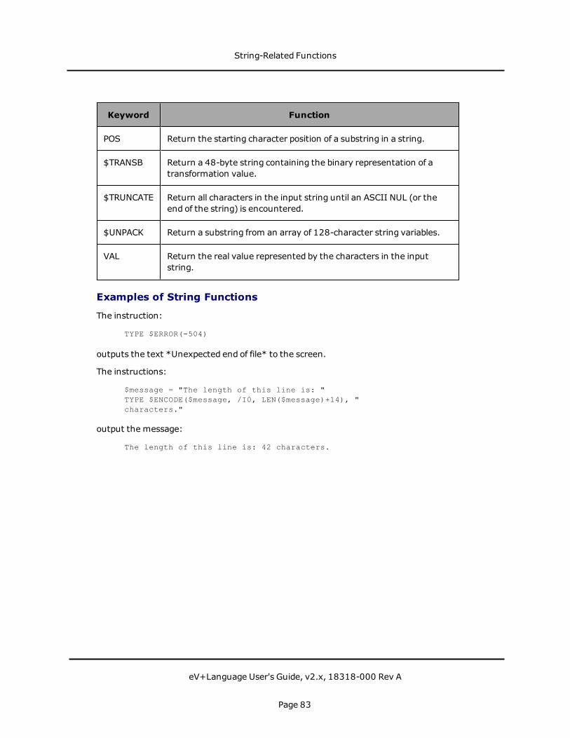
Keyword Function
POS Return the starting character position of a substring in a string.
$TRANSB Return a 48-byte string containing the binary representation of atransformation value.
$TRUNCATE Return all characters in the input string until an ASCII NUL (or theend of the string) is encountered.
$UNPACK Return a substring from an array of 128-character string variables.
VAL Return the real value represented by the characters in the inputstring.
Examples of String Functions
The instruction:
TYPE $ERROR(-504)
outputs the text *Unexpected end of file* to the screen.
The instructions:
$message = "The length of this line is: "TYPE $ENCODE($message, /I0, LEN($message)+14), "characters."
output the message:
The length of this line is: 42 characters.
String-Related Functions
eV+Language User's Guide, v2.x, 18318-000 Rev A
Page 83

Location, Motion, and External Encoder FunctionseV+ provides numerous functions for manipulating and converting location variables. SeeMotion Control Operations for details on motion processing and a table that includes alllocation-related functions. For details on the external encoders, see Reading Device Data onpage 220.
Examples of Location Functions
The instruction:
rotation = RZ(HERE)
places the value of the current rotation about the Z axis in the variable rotation.
The instruction:
dist = DISTANCE(HERE, DEST)
places the distance between the motion device's current location and its destination (thevalue of the next motion instruction) in the variable dist.
The instructions:
IF INRANGE(loc_1) == 0 THENIF SPEED(2) > 50 THEN
SPEED 50ENDMOVE(loc_1)
END
ensures that loc_1 is reachable andmoves the motion device to that location at a programspeed not exceeding 50.
Location, Motion, and External Encoder Functions
eV+Language User's Guide, v2.x, 18318-000 Rev A
Page 84

Numeric Value FunctionsThe functions listed in the following table provide trigonometric, statistical, and data typeconversion operations. For additional details on arithmetic processing, see Data Types andOperators on page 37.
Keyword Function
ABS Return absolute value.
ATAN2 Return the size of the angle (in degrees) that has its trigonometrictangent equal to value_1/value_2.
BCD Convert a real value to Binary Coded Decimal (BCD) format.
COS Return the trigonometric cosine of a given angle.
DCB Convert BCD digits into an equivalent integer value.
FRACT Return the fractional part of the argument.
INT Return the integer part of the value.
MAX Return the maximum value contained in the list of values.
MIN Return the minimum value contained in the list of values.
OUTSIDE Test a value to see if it is outside a specified range.
PI Return the value of the mathematical constant pi (3.141593).
RANDOM Return a pseudorandom number.
SIGN Return the value 1 with the sign of the value parameter.
SIN Return the trigonometric sine of a given angle.
SQR Return the square of the parameter.
SQRT Return the square root of the parameter.
Numeric Value Functions
Examples of Arithmetic Functions
The instructions:
Numeric Value Functions
eV+Language User's Guide, v2.x, 18318-000 Rev A
Page 85

$a = "16"x = SQRT(VAL($a))
results in x having a value of 4.
The instruction:
x = INT(RANDOM*10)
creates a pseudorandom number between 0 and 10.
Numeric Value Functions
eV+Language User's Guide, v2.x, 18318-000 Rev A
Page 86
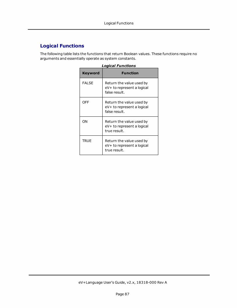
Logical FunctionsThe following table lists the functions that return Boolean values. These functions require noarguments and essentially operate as system constants.
Keyword Function
FALSE Return the value used byeV+ to represent a logicalfalse result.
OFF Return the value used byeV+ to represent a logicalfalse result.
ON Return the value used byeV+ to represent a logicaltrue result.
TRUE Return the value used byeV+ to represent a logicaltrue result.
Logical Functions
Logical Functions
eV+Language User's Guide, v2.x, 18318-000 Rev A
Page 87

System Control FunctionsThe functions listed in the following table return information about the system and systemparameters.
Keyword Function
DEFINED Determine whether a variable has been defined.
ERROR Return the error number of a recent error that caused programexecution to stop or caused a REACTE reaction.
$ERROR Return the error message associated with the given error code.
FREE Return the amount of unused free memory storage space.
GET.EVENT Return events that are set for the specified task.
ID Return values that identify the configuration of the current system.
$ID Return the system creation date and edit/revision information.
INTB Return the value of two bytes of a string interpreted as a signed 16-bit binary integer.
LAST Return the highest index used for an array (dimension).
PARAMETER Return the current setting of the named system parameter.
PRIORITY Return the current reaction lock-out priority for the program.
SELECT Return the unit number that is currently selected by the current taskfor the device named.
STATUS Return status information for an application program.
SWITCH Return an indication of the setting of a system switch.
TAS Return the current value of a real-valued variable and assign it a newvalue. The two actions are done indivisibly so no other program taskcan modify the variable at the same time.
System Control Functions
System Control Functions
eV+Language User's Guide, v2.x, 18318-000 Rev A
Page 88

Keyword Function
TASK Return information about a program execution task.
TIME Return an integer value representing either the date or the timespecified in the given string parameter.
$TIME Return a string value containing either the current system date andtime or the specified date and time.
TIMER Return the current time value of the specified system timer.
TPS Return the number of ticks of the system clock that occur per second(Ticks Per Second).
Example of System Control Functions
The instruction:
IF (TIMER(2) > 100) AND (DEFINED(loc_1)) THENMOVE loc_1
END
executes the MOVE instruction only if timer (2) had a value greater than 100 and thevariable loc_1 had been defined.
System Control Functions
eV+Language User's Guide, v2.x, 18318-000 Rev A
Page 89


Switches and ParametersThe following topics are described in this chapter:
Introduction 93Parameters 94Switches 96
Switches and Parameters
eV+Language User's Guide, v2.x, 18318-000 Rev A
Page 91

Switches and Parameters
eV+Language User's Guide, v2.x, 18318-000 Rev A
Page 92

IntroductionSystem parameters determine certain operating characteristics of the eV+ system. Theseparameters have numeric values that can be changed from the command line or from withina program to suit particular system configurations and needs. The various parameters aredescribed in this chapter alongwith the operations for displaying and changing their values.
System switches are similar to system parameters in that they control the operatingbehavior of the eV+ system. Switches differ from parameters, however, in that they do nothave numeric values. Switches can be set to either enabled or disabled, which can bethought of as on and off, respectively.
All the basic system switches are described in this chapter. The monitor commands andprogram instructions that can be used to display and change their settings are alsopresented.
Introduction
eV+Language User's Guide, v2.x, 18318-000 Rev A
Page 93
ParametersSee the eV+ Language Reference Guide for more detailed descriptions of the keywordsdiscussed here.
Whenever a system parameter name is used, it can be abbreviated to the minimum lengthrequired to identify the parameter. For example, the HAND.TIME parameter can beabbreviated to H, since no other parameter name begins with H.
Viewing Parameters
To see the state of a single parameter, use the PARAMETERmonitor command:
PARAMETER parameter_name
If parameter_name is omitted, the value of all parameters is displayed.
To retrieve the value of a parameter from within a program, use the PARAMETER function.The instruction:
TYPE "HAND.TIME parameter =", PARAMETER(HAND.TIME)
will display the current setting of the hand-delay parameter in the monitor window.
The PARAMETER function can be used in any expression to include the value of a parameter.For example, the following program statement increases the delay for hand actuation:
PARAMETER HAND.TIME = PARAMETER(HAND.TIME) + 0.15
Note that the left-hand occurrence of PARAMETER is the instruction name and the right-handoccurrence is the function name.
Setting Parameters
To set a parameter from the command line, use the PARAMETERmonitor command. Thecommand:
PARAMETER HAND.TIME = 0.5
sets the hand operation delay time to 0.5 seconds.
To set a parameter in a program, use the PARAMETER program instruction. The instruction:
PARAMETER NOT.CALIBRATED = 1
asserts the not calibrated state for robot 1.
Some parameters are organized as arrays andmust be accessed by specifying an array index.
Parameters
eV+Language User's Guide, v2.x, 18318-000 Rev A
Page 94

Summary of Basic System Parameters
System parameters are set to defaults when the eV+ system is initialized. The default valuesare indicated with each parameter description below. The settings of the parameter valuesare not affected by the ZERO command.
If your robot system includes optional enhancements (such as vision), you will have othersystem parameters available. Consult the documentation for the options for details. Thebasic system parameters are shown in the following table.
Parameter Use De-fault Min Max
BELT.MODE Controls the operation of the conveyortracking feature of the eV+ system.
0 0 14
HAND.TIME Determines the duration of the motiondelay that occurs during processing ofOPENI, CLOSEI, and RELAXIinstructions. The value for thisparameter is interpreted as thenumber of seconds to delay. Due tothe way in which eV+ generates itstime delays, the HAND.TIMEparameter is internally rounded to thenearest multiple of 0.016 seconds.
0.05 0 1E18
NOT.CALIBRATED Represents the calibration status ofthe robot(s) controlled by the eV+system.
7 0 7
Basic System Parameters
Parameters
eV+Language User's Guide, v2.x, 18318-000 Rev A
Page 95

SwitchesSystem switches govern various features of the eV+ system. The switches are describedbelow. See the eV+ Language Reference Guide and the eV+ Operating System ReferenceGuide for more detailed descriptions of the keywords discussed here.
As with system parameters, the names of system switches can be abbreviated to theminimum length required to identify the switch.
Viewing Switch Settings
The SWITCHmonitor command displays the setting of one or more system switches:
SWITCH switch_name, ..., switch_name
If no switches are specified, the settings of all switches are displayed.
Within programs, the SWITCH real-valued function returns the status of a switch. Theinstruction:
SWITCH(switch_name)
returns TRUE (-1.0) if the switch is enabled, FALSE (0.0) if the switch is disabled.
Some switches are organized as arrays andmay be accessed by specifying the array index.
Setting Switches
The ENABLE and DISABLE monitor commands/program instructions control the setting ofsystem switches. The instruction:
ENABLE BELT
enables the BELT switch. The instruction:
DISABLE BELT, CP
disables the CP and BELT switches. Multiple switches can be specified for either instruction.
Switches can also be set with the SWITCH program instruction. Its syntax is:
SWITCH switch_name = value
This instruction differs from the ENABLE and DISABLE instructions in that the SWITCHinstruction enables or disables a switch depending on the value on the right-hand side of theequal sign. This allows you to set switches based on a variable or expression. The switch isenabled if the value is TRUE (nonzero) and disabled if the value is FALSE (zero). Theinstruction:
SWITCH CP = SIG(1001)
enables the continuous path (CP) switch if input signal 1001 is on.
Switches
eV+Language User's Guide, v2.x, 18318-000 Rev A
Page 96
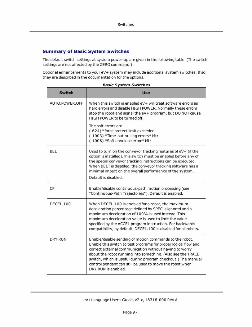
Summary of Basic System Switches
The default switch settings at system power-up are given in the following table. (The switchsettings are not affected by the ZERO command.)
Optional enhancements to your eV+ system may include additional system switches. If so,they are described in the documentation for the options.
Switch Use
AUTO.POWER.OFF When this switch is enabled eV+ will treat software errors ashard errors and disable HIGH POWER. Normally these errorsstop the robot and signal the eV+ program, but DONOT causeHIGH POWER to be turned off.
The soft errors are:(-624) *force protect limit exceeded(-1003) *Time-out nulling errors* Mtr(-1006) *Soft envelope error* Mtr
BELT Used to turn on the conveyor tracking features of eV+ (if theoption is installed).This switch must be enabled before any ofthe special conveyor tracking instructions can be executed.When BELT is disabled, the conveyor tracking software has aminimal impact on the overall performance of the system.
Default is disabled.
CP Enable/disable continuous-path motion processing (see"Continuous-Path Trajectories"). Default is enabled.
DECEL.100 When DECEL.100 is enabled for a robot, the maximumdeceleration percentage defined by SPEC is ignored and amaximum deceleration of 100% is used instead. Thismaximum deceleration value is used to limit the valuespecified by the ACCEL program instruction. For backwardscompatibility, by default, DECEL.100 is disabled for all robots.
DRY.RUN Enable/disable sending of motion commands to the robot.Enable this switch to test programs for proper logical flow andcorrect external communication without having to worryabout the robot running into something. (Also see the TRACEswitch, which is useful during program checkout.) The manualcontrol pendant can still be used tomove the robot whenDRY.RUN is enabled.
Basic System Switches
Switches
eV+Language User's Guide, v2.x, 18318-000 Rev A
Page 97

Switch Use
Default is disabled.
FORCE Controls whether the (optional) stop-on-force feature of theeV+ system is active. Default is disabled.
MESSAGES Controls whether output from TYPE instructions will bedisplayed on the terminal. Default is enabled.
POWER Tracks the status of Robot Power. This switch is automaticallyenabled whenever Robot Power is turned on. This switch canbe used to turn Robot Power on or off-enabling the switchturns on Robot Power and disabling the switch turns off RobotPower. Default is disabled.
ROBOT This is an array of switches that control whether or not thesystem should access robots normally controlled by thesystem.Default is disabled.
UPPER Determines whether comparisons of string values will considerlowercase letters the same as uppercase letters. When thisswitch is enabled, all lowercase letters are considered asthough they are uppercase. Default is enabled.
Switches
eV+Language User's Guide, v2.x, 18318-000 Rev A
Page 98

Motion Control OperationsThe following topics are described in this chapter:
Introduction 101Location Variables 102Creating and Altering Location Variables 109Motion Control Instructions 116Tool Transformations 124Summary of Motion Keywords 126
Motion Control Operations
eV+Language User's Guide, v2.x, 18318-000 Rev A
Page 99

Motion Control Operations
eV+Language User's Guide, v2.x, 18318-000 Rev A
Page 100
IntroductionA primary focus of the eV+ language is to drive motion devices. This chapter discusses thelanguage elements that generate controller output to move amotion device from onelocation to another. Before we introduce the eV+ motion instructions, we should examinethe eV+ location variables and see how they relate to the space in which the motion deviceoperates.
Introduction
eV+Language User's Guide, v2.x, 18318-000 Rev A
Page 101

Location VariablesLocations can be specified in two ways in eV+: transformations and precision points.
A transformation is a set of six components that uniquely identifies a location in Cartesianspace and the orientation of the motion device end-of-arm tooling at that location. Atransformation can also represent the location of an arbitrary local reference frame.
A precision point includes an element for each joint in the motion device. Rotational jointvalues are measured in degrees; translational joint values are measured in millimeters.These values are absolute with respect to the motion device's home sensors and cannot bemade relative to other locations or coordinate frames.
Coordinate Systems
The following figure shows the world coordinate system for an Omron Adept SCARA robot andan Omron Adept Cartesian robot. Ultimately, all transformations are based on a worldcoordinate system. The eV+ language contains several instructions for creating localreference frames, building relative transformations, and changing the origin of the base(world) coordinate frame. Therefore, an individual transformation may be relative to anothertransformation, a local reference frame, or an altered base reference frame.
Different robots andmotion devices designates different locations as the origin of the worldcoordinate system. See the user's guide for Omron Adept robots to determine the origin andorientation of the world coordinate frame.
Location Variables
eV+Language User's Guide, v2.x, 18318-000 Rev A
Page 102

Omron Adept Robot Cartesian Space
Transformations
The first three components of a transformation variable are the values for the points on theX, Y, and Z axes. In an Omron Adept SCARA robot, the origin of this Cartesian space is thebase of the robot. The Z axis points straight up through the middle of the robot column. TheX axis points straight out, and the Y axis runs left to right as you face the robot. The firstrobot in the figure Omron Adept Robot Cartesian Space shows the orientation of theCartesian space for an Omron Adept SCARA robot. The location of the world coordinatesystem for other robots andmotion devices depends on the kinematic model of the motiondevice. For example, the second robot in the figure Omron Adept Robot Cartesian Spaceshows the world coordinate frame for a robot built on the Cartesian coordinate model. Seethe kinematic device module documents for your particular motion device.
When a transformation is defined, a local reference frame is created at the X, Y, Z locationwith all three local frame axes parallel to the world coordinate frame. The figure XYZElements of a Transformation shows the first part of a transformation. This transformationhas the value X = 30, Y = 100, Z = 125, yaw = 0, pitch = 0, and roll = 0.
Location Variables
eV+Language User's Guide, v2.x, 18318-000 Rev A
Page 103

XYZ Elements of a Transformation
The second three components of a transformation variable specify the orientation of the end-of-arm tooling. These three components are yaw, pitch, and roll. These elements are figuredas ZYZ' Euler values. The following figures demonstrate how these values are interpreted.
Yaw
Yaw is a rotation about the local reference frame Z axis. This rotation is not about the primaryreference frame Z axis, but is centered at the origin of the local frame of reference. The figureYaw shows the yaw axis with a rotation of 30 degrees. Note that it is parallel to the primaryreference frame Z axis but may be centered at any point in that space. In this example, theyaw value is 30 degrees, resulting in a transformation with the value (X = 30, Y = 100, Z =125, yaw = 30, pitch = 0, and roll = 0).
Location Variables
eV+Language User's Guide, v2.x, 18318-000 Rev A
Page 104

When you are using a robot, the local frame of reference defined by the XYZ components islocated at the end of the robot tool flange. (This local reference frame is referred to as thetool coordinate system.) In the figure Yaw, the large Cartesian space represents a worldcoordinate system. The small Cartesian space represents a local tool coordinate system(which is centered at the motion device tooling flange).
Yaw
Location Variables
eV+Language User's Guide, v2.x, 18318-000 Rev A
Page 105

Pitch
Pitch is defined as a rotation about the local reference frame Y axis, after yaw has beenapplied. The figure Pitch shows the local reference frame with a yaw of 30 degrees and a pitchof 40 degrees.
For example, deflection of a wrist joint is reflected in the pitch component. The movement ofa fifth axis on a SCARA robot is reflected in the pitch component. In this example, the motiondevice end-of-arm tooling has a pitch of 40 degrees, resulting in a transformation with thevalue (X = 30, Y = 100, Z = 125, yaw = 30, pitch = 40, and roll = 0). This location can bereached only by amechanism with a fifth axis. Pitch is represented as ±180°, not as 360° ofrotation. Thus, a positive rotation of 190° is shown as -170 degrees.
Location Variables
eV+Language User's Guide, v2.x, 18318-000 Rev A
Page 106
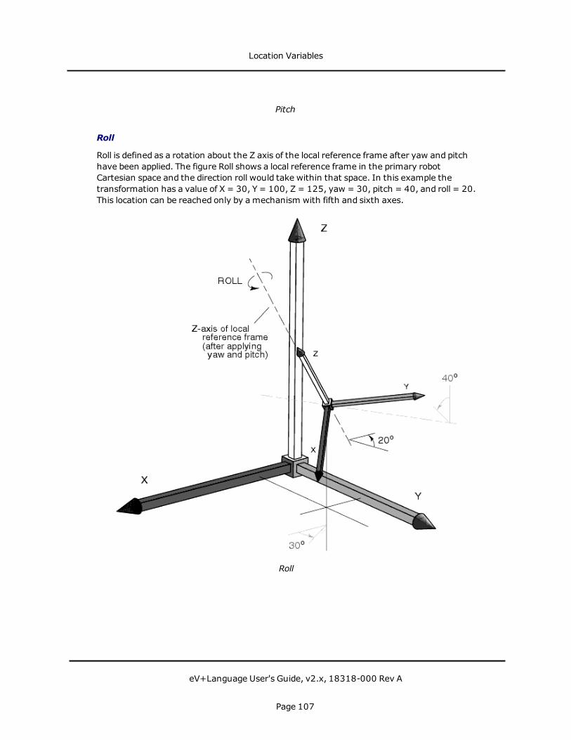
Pitch
Roll
Roll is defined as a rotation about the Z axis of the local reference frame after yaw and pitchhave been applied. The figure Roll shows a local reference frame in the primary robotCartesian space and the direction roll would take within that space. In this example thetransformation has a value of X = 30, Y = 100, Z = 125, yaw = 30, pitch = 40, and roll = 20.This location can be reached only by amechanism with fifth and sixth axes.
Roll
Location Variables
eV+Language User's Guide, v2.x, 18318-000 Rev A
Page 107

Special Situations
When the Z axes of the local and primary reference frames are parallel, roll and yaw producethe samemotion in the same plane, although the twomotions may be in different directions.This is always the case with a four-axis SCARA robot. The system automatically reflectsrotation of the quill in the roll component of a transformation variable, and the yawcomponent is forced to 0 degrees. In a SCARA robot equippedwith a fifth axis, rotation of thequill is reflected in the yaw component andmotion of a rotating end-effector (sixth axis) isreflected in the roll component.
Notice in the figure XYZ Elements of a Transformation that the local reference frame pointsstraight up. This corresponds to a situation where the end of arm tooling points straight backalong the third axis. In a mechanism not equippedwith a 360 degree wrist, this is animpossible position. For a four-axis SCARA, this component must point straight down (pitch =180 degrees). For a mechanism with a fifth axis, this component must be within the range ofmotion of the fifth axis.
NOTE:When thinking about a transformation, remember that the rules of ZYZ' Eulerangles require that the orientation components be applied in order after the localreference frame has been defined. After calculating the Cartesian components and placinga local reference frame with x, y, and z axes parallel to the primary reference frame X, Y,and Z axes, the orientation components are applied in a strict order—yaw is applied first,then pitch, and, finally, roll.
Location Variables
eV+Language User's Guide, v2.x, 18318-000 Rev A
Page 108

Creating and Altering Location Variables
Creating Location Variables
The most straightforwardmethod of creating a location variable is to place the robot ormotion device at a location and enter the monitor command:
HERE loc_name
Transformations vs. Precision Points
A location can be specified using either the six components described in the previous section,or by specifying the state the robot joints would be in when a location is reached. The formermethod results in a transformation variable. Transformations are the most flexible andefficient location variables.
Precision points record the joint values of each joint in the motion device. Precision pointsmay be more accurate, and they are the only way of extracting joint information that willallow you tomove an individual joint. Precision points are identified by a leading pound sign(#). The command:
HERE #pick
will create the precision point #pick equal to the current robot joint values.
Modifying Location Variables
A location variable can be duplicated using the SET program instruction. The programinstruction:
SET loc_name = loc_value
results in the variable loc_name being given the value of loc_value.
The following functions return transformation values:
TRANS Create a location by specifying individual components of a transformation. A valuecan be specified for each component.SHIFT Alter the Cartesian components of an existing transformation.
The SET operation can be used in conjunction with the transformation functions SHIFT andTRANS to create location variables based on specific modifications of existing variables.
SET loc_name = SHIFT(loc_value BY 5, 5, 5)
will create the location variable loc_name. The location of loc_name are shifted 5 mm in thepositive X, Y, and Z directions from loc_value.
Creating and Altering Location Variables
eV+Language User's Guide, v2.x, 18318-000 Rev A
Page 109

Relative Transformations
Relative transformations allow you tomake one location relative to another and to build localreference frames to which that transformations can be relative. For example, you may bebuilding an assembly whose location in the workcell changes periodically. If all the locationson the assembly are taught relative to the world coordinate frame, each time the assembly islocated differently in the workcell, all the locations must be retaught. If, however, you createa frame based on identifiable features of the assembly, you will have to reteach only thepoints that define the frame.
Examples of Modifying Location Variables
The figure Relative Transformation shows how relative transformations work. The magnitudeand direction elements (x, y, z), but not the orientation elements (y, p, r), of an Omron Adepttransformation can be represented as a 3-D vector, as shown by the dashed lines and arrowsin the figure Relative Transformation. The following code generates the locations shown inthat figure.
; Define a simple transformationSET loc_a = TRANS(300,50,350,0,180,0)
; Move to the locationMOVE loc_aBREAK
; Move to a location offset -50mm in X, 20mm in Y,; and 30mm in Z relative to "loc_a"
MOVE loc_a:TRANS(-50, 20, 30)BREAK
; Define "loc_b" to be the current location relative; to "loc_a"
HERE loc_a:loc_b ;loc_b = -50, 20, 30, 0, 0, 0BREAK
; Define "loc_c" as the vector sum of "loc_a" and "loc_b"SET loc_c = loc_a:loc_b ;loc_c = 350, 70, 320, 0, 180, 0
Once this code has run, loc_b exists as a transformation that is completely independent ofloc_a. The following instruction moves the robot another -50 mm in the x, 20 mm in the y,and 30 mm in the z direction (relative to loc_c):
MOVE loc_c:loc_b
Multiple relative transformations can be chained together. If we define loc_d to have thevalue 0, 50, 0, 0, 0, 0:
SET loc_d = TRANS(0,50)
and then issue the followingMOVE instruction:
MOVE loc_a:loc_b:loc_d
the robot moves to a position x = -50 mm, y =70 mm, and z = 30 mm relative to loc_a.
Creating and Altering Location Variables
eV+Language User's Guide, v2.x, 18318-000 Rev A
Page 110

In the figure Relative Transformation, the transformation loc_b defines the transformationneeded to get from the local reference frame defined by loc_a to the local reference framedefined by loc_c.
The transformation needed to go in the opposite direction (from loc_c to loc_a) can becalculated by:
INVERSE(loc_b)
Thus, the instruction:
MOVE loc_c:INVERSE(loc_b)
effectively moves the robot back to loc_a.
Creating and Altering Location Variables
eV+Language User's Guide, v2.x, 18318-000 Rev A
Page 111
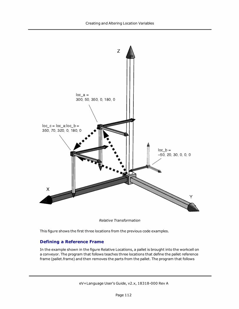
Relative Transformation
This figure shows the first three locations from the previous code examples.
Defining a Reference Frame
In the example shown in the figure Relative Locations, a pallet is brought into the workcell ona conveyor. The program that follows teaches three locations that define the pallet referenceframe (pallet.frame) and then removes the parts from the pallet. The program that follows
Creating and Altering Location Variables
eV+Language User's Guide, v2.x, 18318-000 Rev A
Page 112

runs regardless of where the pallet is placed in the workcell as long as it is within the robot'sworking envelope.
Relative Locations
; Get the locations to define the pallet
DETACH () ;Release robot for use by the MCPPROMPT "Place robot at pallet origin. ", $ansHERE loc.origin ;Record the frame origin
PROMPT "Place robot at point on the pallet x-axis. ", $ansHERE loc.x.axis ;Record point on x-axis
PROMPT "Place robot at point in positive y direction. ", $ansHERE loc.pos.y ;Record positive y direction
ATTACH () ;Reattach the robot
Creating and Altering Location Variables
eV+Language User's Guide, v2.x, 18318-000 Rev A
Page 113

; Create the local reference frame "pallet.frame"
SET pallet.frame = FRAME(loc.origin, loc.x.axis,loc.pos.y, loc.origin)
cell.space = 50 ;Spacing of cells on pallet
; Remove the palletized items
FOR i = 0 TO 3FOR J = 0 TO 2
APPRO pallet.frame:TRANS(i*cell.space, j*cell.space), 25MOVE pallet.frame:TRANS(i*cell.space, j*cell.space)BREAK ;Settle robotCLOSEI ;Grab the partDEPART 25 ;MOVE to the drop off location
ENDEND
In the above example, the code that teaches the pallet framemust run only when the palletlocation changes.
If you are building an assembly that does not have regularly spaced locations like the aboveexample, the following code teaches individual locations relative to the frame:
; Get the locations to define the pallet frame
DETACH () ;Release robot for use by the MCPPROMPT "Place robot at assembly origin. ", $ansHERE loc.origin ;Record the frame origin
PROMPT "Place robot at point on the assm. x-axis. ", $ansHERE loc.x.axis ;Record point on x-axis
PROMPT "Place robot at point in positive y direction. ", $ansHERE loc.pos.y ;Record positive y direction
; Create the local reference frame "assm.frame"
SET assm.frame = FRAME(loc.origin, loc.x.axis, loc.pos.y, loc.origin)
; Teach the locations on the assembly
PROMPT "Place the robot in the first location. ", $ansHERE assm.frame:loc.1 ;Record the first location
PROMPT "Place the robot in the second location. ", $ansHERE assm.frame:loc.2 ;Record the second location
; etc.
; Move to the locations on the assembly
ATTACH () ;Reattach the robot
Creating and Altering Location Variables
eV+Language User's Guide, v2.x, 18318-000 Rev A
Page 114

APPRO assm.frame:loc.1, 25MOVE assm.frame:loc.1;Activate gripperDEPART 25
APPRO assm.frame:loc.1, 25MOVE assm.frame:loc.2;Activate gripperDEPART 25
; etc.
In the above example, the framemust be taught each time the assembly moves-thelocations on the assembly must be taught only once.
The instruction HERE assm.frame:loc.1 tells the system to record the location loc.1 relativeto assm.frame rather than relative to the world coordinate frame. If a subassembly is beingbuilt relative to loc.1, the instruction:
HERE assm.frame:loc.1:sub.loc.1
creates a compound transformation where sub.loc.1 is relative to the transformationassm.frame:loc.1.
Miscellaneous Location Operations
The instruction:
DECOMPOSE array_name[] = #loc_name
places the joint values of #loc_name in the array array_name. DECOMPOSE works withtransformations and precision points.
The command:
WHERE
displays the current robot location.
Creating and Altering Location Variables
eV+Language User's Guide, v2.x, 18318-000 Rev A
Page 115

Motion Control InstructionseV+ processes robot motion instructions differently from the way you might expect. WitheV+, a motion instruction such as MOVE part is interpreted tomean start moving the robot tolocation 'part'. As soon as the robot starts moving to the specified destination, the eV+program continues without waiting for the robot motion to complete. The instructionsequence:
MOVE part.1SIGNAL 1MOVE part.2SIGNAL 2
causes external output signal #1 to be turned on immediately after the robot begins movingto part.1, rather than waiting for it to arrive at the location. When the secondMOVEinstruction is encountered, eV+ waits until the motion to part.1 is completed. Externaloutput signal #2 is turned on just after the motion to part.2 begins. This is known as forwardprocessing. See Breaking Continuous-Path Operation for details on how to defeat forwardprocessing.
This parallel operation of program execution and robot motion makes possible the proceduralmotions described later in this chapter.
Basic Motion Operations
Joint-Interpolated Motion vs. Straight-Line Motion
The path a motion device takes when moving from one location to another can be either ajoint-interpolatedmotion or a straight-line motion. Joint-interpolatedmotions move eachjoint at a constant velocity (except during the acceleration/deceleration phases-see RobotSpeed). Typically, the robot tool tipmoves in a series of arcs that represents the leastprocessing-intensive path the trajectory generator can formulate. Straight-line motionsensure that the robot tool tip traces a straight line, useful for cutting a straight line or laying abead of sealant. The instruction:
MOVE pick
causes the robot to move to the location pick using joint-interpolatedmotion. Theinstruction:
MOVES pick
causes the robot to move the pick using a straight-line motion.
Safe Approaches and Departures
In many cases you will want to approach a location from a distance offset along the tool Z axisor depart from a location along the tool Z axis before moving to the next location. Forexample, if you were inserting components into a crowded circuit board, you would want the
Motion Control Instructions
eV+Language User's Guide, v2.x, 18318-000 Rev A
Page 116

robot arm to approach a location from directly above the board so nearby parts are notdisturbed. Assuming you were using a four-axis Omron Adept robot, the instructions:
APPRO place, 50MOVE placeDEPART 50
causes joint-interpolatedmotion to a point 50 mm above place, movement down to place,andmovement straight up to 50 mm above place.
If the instructions APPROS, DEPARTS, andMOVES had been used, the motions would havebeen straight line instead of joint interpolated.
NOTE:Approaches and departs are based on the tool coordinate system, not the worldcoordinate system. Thus, if the location specifies a pitch of 135 degrees, the robot willapproach at a 45 degree angle relative to the world coordinate system. For a descriptionof the tool coordinate system, see Yaw on page 104.
Moving an Individual Joint
You can move an individual joint of a robot using the instruction DRIVE. The instructions:
DRIVE 2,50.0, 100DRIVE 3,25, 100
moves joint 2 through 50 degrees of motion and then move joint 3 a distance of 25 mm atSPEED 100%.
End-Effector Operation Instructions
The instructions described in this section depend on the use of two digital signals. They areused to open, close, or relax a gripper. The utility program SPEC specifies which signalscontrol the end effector. See the Instructions for Adept Utility Programs.
The instruction OPEN opens the gripper during the ensuingmotion instruction. Theinstruction OPENI opens the gripper before any additional motion instructions are executed.CLOSE and CLOSEI are the complementary instructions.
When an OPEN(I) or CLOSE(I) instruction is issued, one solenoid is activated and the other isreleased. To completely relax both solenoids, use the instruction RELAX or RELAXI.
Use the system parameter HAND.TIME to set the duration of the motion delay that occursduring an OPENI, CLOSEI, or RELAXI instruction.
Use the function HAND to return the current state of the gripper.
Continuous-Path Trajectories
When a single motion instruction is processed, such as the instruction:
Motion Control Instructions
eV+Language User's Guide, v2.x, 18318-000 Rev A
Page 117

MOVE pick
the robot begins moving toward the location by accelerating smoothly to the commandedspeed. Sometime later, when the robot is close to the destination location pick, the robotdecelerates smoothly to a stop at location pick. This motion is referred to as a single motionsegment, since it is produced by a single motion instruction.
When a sequence of motion instructions is executed, such as:
MOVE loc.1MOVE loc.2
the robot begins moving toward loc.1 by accelerating smoothly to the commanded speed1just as before. However, the robot does not decelerate to a stop when it gets close to loc.1.Instead, it smoothly changes its direction and begins moving toward loc.2. Finally, when therobot is close to loc.2, it decelerates smoothly to a stop at loc.2. This motion consists of twomotion segments since it is generated by twomotion instructions.
Making smooth transitions between motion segments without stopping the robot motion iscalled continuous-path operation. That is the normal method eV+ uses to perform robotmotions. If desired, continuous-path operation can be disabled with the CP switch. When theCP switch is disabled, the robot decelerates and stops at the end of each motion segmentbefore beginning tomove to the next location.
NOTE: Disabling continuous-path operation does not affect forward processing (theparallel operation of robot motion and program execution).
Continuous-path transitions can occur between any combination of straight-line and joint-interpolatedmotions. For example, a continuousmotion could consist of a straight-linemotion (for example, DEPARTS) followed by a joint-interpolatedmotion (for example, APPRO)and a final straight-line motion (for example, MOVES). Any number of motion segments canbe combined this way.
Breaking Continuous-Path Operation
Certain eV+ program instructions cause program execution to be suspended until the currentrobot motion reaches its destination location and comes to a stop. This is called breakingcontinuous path. Such instructions are useful when the robot must be stoppedwhile someoperation is performed (for example, closing the hand). Consider the instruction sequence:
MOVE loc.1BREAKSIGNAL 1
The MOVE instruction starts the robot moving to loc.1. Program execution then continuesand the BREAK instruction is processed. BREAK causes the eV+ program to wait until themotion to loc.1 completes. The external signal is not turned on until the robot stops. (Recallthat without the BREAK instruction the signal would be turned on immediately after themotion to loc.1 starts.)
Motion Control Instructions
eV+Language User's Guide, v2.x, 18318-000 Rev A
Page 118

The following instructions always cause eV+ to suspend program execution until the robotstops (see the eV+ Language Reference Guide for detailed information on theseinstructions):
BREAK CLOSEI CPOFF DETACH (0)
HALT OPENI PAUSE RELAXI TOOL
Also, the robot decelerates to a stop when the BRAKE (not to be confusedwith BREAK)instruction is executed (by any program task), andwhen the reaction associated with aREACTI instruction is triggered. These events could happen at any point within a motionsegment. (Note that these events can be initiated from a different program task.)
The robot also decelerates and comes to a stop if no new motion instruction is encounteredbefore the current motion completes. This situation can occur for a variety of reasons:
l AWAIT or WAIT.EVENT instruction is executed and the wait condition is not satisfiedbefore the robot motion completes.
l A PROMPT instruction is executed and no response is entered before the robot motioncompletes.
l The eV+ program instructions between motion instructions take longer to executethan the robot takes to perform its motion.
Procedural Motion
The ability to move in straight lines and joint-interpolated arcs is built into the basicoperation of eV+. The robot tool can also move along a path that is prerecorded, or describedby amathematical formula. Such motions are performed by programming the robottrajectory as the robot is moving. Such a program is said to perform a procedural motion.
A procedural motion is a program loop that computes many short motions and issues theappropriate motion requests. The parallel execution of robot motions and non-motioninstructions allows each successive motion to be definedwithout stopping the robot. Thecontinuous-path feature of eV+ automatically smoothes the transitions between thecomputedmotion segments.
Procedural Motion Examples
Two simple examples of procedural motions are described below. In the first example, therobot tool is moved along a trajectory described by locations stored in the array path. (TheLAST function is used to determine the size of the array.)
SPEED 0.75 IPS ALWAYSFOR index = 0 TO LAST(path[])
MOVES path[index]END
Motion Control Instructions
eV+Language User's Guide, v2.x, 18318-000 Rev A
Page 119

The robot tool moves at the constant speed of 0.75 inch per second through each locationdefined in the array path[].
In the next example, the robot tool is to be moved along a circular arc. However, the path isnot prerecorded-it is describedmathematically, based on the radius and center of the arc tobe followed.
The program segment below assumes that a real variable radius has already been assignedthe radius of the desired arc, and x.center and y.center have been assigned the respectivecoordinates of the center of curvature. The variables start and last are assumed to have beendefined to describe the portion of the circle to be traced. Finally, the variable angle.step isassumed to have been defined to specify the (angular) increment to be traversed in eachincremental motion. (Because the DURATION instruction is used, the program moves therobot tool angle.step degrees around the arc every 0.5 second.)
When this program segment is executed, the X and Y coordinates of points on the arc arerepeatedly computed. They are then used to create a transformation that defines thedestination for the next robot motion segment.
DURATION 0.5 ALWAYSFOR angle = start TO last STEP angle.step
x = radius*COS(angle)+x.centery = radius*SIN(angle)+y.centerMOVE TRANS(x, y, 0, 0, 180, 0)
END
Timing Considerations
Because of the computation time required by eV+ to perform the transitions between motionsegments, there is a limit on how closely spaced commanded locations can be.Whenlocations are too close together, there is not enough time for eV+ to compute and performthe transition from onemotion to the next, and there will be a break in the continuous-pathmotion. This means that the robot stops momentarily at intermediate locations.
The minimum spacing that can be used between locations before this effect occurs isdetermined by the time required to complete the motion from one location to the next.Straight-line motions can be used if the motion segments take more than about 32milliseconds each. Joint-interpolatedmotions can be usedwith motion segments as short asabout 16 milliseconds each.
NOTE:The standard trajectory generation frequency is 62.5 Hz. With an optional softwarelicense, trajectory frequencies of 125 Hz, 250 Hz, and 500 Hz are possible.
The minimum motion times for joint and straight-line motions must be greater than orequal to the configured trajectory cycle time. As a convenience, if they are set to be lessthan the configured trajectory cycle time (for example 0), the trajectory cycle time is usedas the minimum motion time.
Motion Control Instructions
eV+Language User's Guide, v2.x, 18318-000 Rev A
Page 120
Robot Speed
A robot move has three phases: an acceleration phase where the robot accelerates to themaximum speed specified for the move, a velocity phase where the robot moves at a ratenot exceeding the specifiedmaximum speed, and a deceleration phase where the robotdecelerates to a stop (or transitions to the next motion).
Robot speed can mean two things: how fast the robot moves between the acceleration anddeceleration phases of a motion (referred to in this manual as robot speed), or how fast therobot gets from one place to another (referred to in this manual as robot performance).
The robot speed between the acceleration and deceleration phases is specified as either apercentage of normal speed or an absolute rate of travel of the robot tool tip. Speed set as apercentage of normal speed is the default. The speed of a robot move based on normal speedis determined by the following factors:
l The program speed (set with the SPEED program instruction). This speed is set to 100when program execution begins.
l The monitor speed (set with the SPEEDmonitor command or a SPEED programinstruction that specifies MONITOR). This speed is normally set to 50 at systemstartup(start-up SPEED can be set with the ACE Controller Config Tools). (The effectsof the two SPEED operations are slightly different. See the SPEED program instructionfor further details.)
Robot speed is the product of these two speeds. With monitor speed and programspeed set to 100, the robot moves at its normal speed.With monitor speed set to 50and program speed set to 50, the robot moves at 25% of its normal speed.
Tomove the robot tool tip at an absolute rate of speed, a speed rate in inches per second ormillimeters per second is specified in the SPEED program instruction. The instruction:
SPEED 25 MMPS ALWAYS
specifies an absolute tool tip speed of 25 millimeters per second for all robot motions until thenext SPEED instruction. In order for the tool tip to actually move at the specified speed:
l The monitor speedmust be 100.
l The locations must be far enough apart so that the robot can accelerate to the desiredspeed and decelerate to a stop at the end of the motion.
Robot performance is a function of the SPEED settings and the following factors:
l The robot acceleration profile and ACCEL settings. The default acceleration profile isbased on a normal maximum rate of acceleration and deceleration. The ACCELcommand can scale down these maximum rates so that the robot acceleration and/ordeceleration takes more time.
You can also define optional acceleration profiles that alter the maximum rate ofchange for acceleration and deceleration
Motion Control Instructions
eV+Language User's Guide, v2.x, 18318-000 Rev A
Page 121
l The location tolerance settings (COARSE/FINE, NULL/NONULL) for the move. Themore accurately a robot must get to the actual location, the more time the move willtake.
l Any DURATION setting. DURATION forces a robot move to take aminimum time tocomplete regardless of the SPEED settings.
l The maximum allowable velocity. For Omron Adept robots, maximum velocity isfactory set.
l The inertial loading of the robot and the tuning of the robot.
l Straight-line vs. joint-interpolatedmotions-for complex geometries, straight-line andjoint-interpolated paths produce different dynamic responses and, therefore, differentmotion times.
Robot performance for a given application can be greatly enhanced or severely degraded bythese settings. For example:
l A heavily loaded robot may actually show better performance with slower SPEED andACCEL settings, which lessens overshoot at the end of a move and allows the robot tosettle more quickly.
l Applications such as picking up bags of product with a vacuum gripper do not requirehigh accuracy and can generally run faster with a COARSE tolerance.
Motion Modifiers
The following instructions modify the characteristics of individual motions. These instructionsare summarized in Motion Control Operations.
NOTE:The instructions listed below with an asterisk (*) can take ALWAYS as anargument.
l ABOVE/BELOWl ACCELl BREAKl COARSE/FINE*l CPON/CPOFFl DURATION*l FLIP/NOFLIPl LEFTY/RIGHTYl NOOVERLAP/OVERLAP*l NULL/NONULL*BRAKEl SINGLE/MULTIPLE*l SPEED*
Motion Control Instructions
eV+Language User's Guide, v2.x, 18318-000 Rev A
Page 122

Customizing the Calibration Routine
The following information is required only if you need to customize the calibration sequence.Most AdeptMotion users do not need to do this.
When a CALIBRATE command or instruction is processed, the eV+ system loads the fileCAL_UTIL.V2 (see the dictionary page for the CALIBRATE command for details) and executesa program contained in that file. The main calibration program then examines the SPEC datafor the robot to determine the name of the disk file that contains the specific calibrationprogram for the current robot, and the name of that program.
The standard routine used for AdeptMotion devices is stored on the system disk in\CALIB\STANDARD.CAL (and the routine is named .standard.cal). That file is protected andthus cannot be viewed. However, a read-only copy of the file is provided, in\CALIB\STANDARD.V2, as a basis for developing a custom calibration routine that can thenbe substituted for the standard file. (The name of the robot-specific calibration file andprogram can be changed using the ACE Controller Config Tools..)
1See the SPEEDmonitor command and SPEED program instructions.
Motion Control Instructions
eV+Language User's Guide, v2.x, 18318-000 Rev A
Page 123

Tool TransformationsA tool transformation is a special transformation that is used to account for robot grippers (orparts held in grippers) that are offset from the center of the robot tool flange. If a location istaught using a part secured by an offset gripper, the actual location recorded is not the partlocation, but the center of the tool flange to which the offset gripper is attached, as shown inthe following figure. If the same location is taught with a tool transformation in place, thelocation recorded is the center of the gripper, not the center of the tool flange. This allows youto change grippers and still have the robot reach the correct location. The following figureshows the location of the robot when a location is taught and the actual location that isrecordedwhen no tool transformation is in effect. If the proper tool transformation is in effectwhen the location is taught, the location recordedwill be the part location and not the centerof the tool flange.
Recording Locations
Tool transformations are most important when:
l Grippers are changed frequently
l The robot is vision guided
l Robot locations are loaded directly from CAD data
Tool Transformations
eV+Language User's Guide, v2.x, 18318-000 Rev A
Page 124

Defining a Tool Transformation
A tool transformation can be defined using the Tool Offset wizard, which is available in theGripper object editor in the ACE software. The Tool Offset wizard will ask you questions aboutthe application, and then calculate the proper tool offset, based on your responses. For moredetails, see the Gripper Editor topic in the ACE User's Guide.
Tool Transformations
eV+Language User's Guide, v2.x, 18318-000 Rev A
Page 125
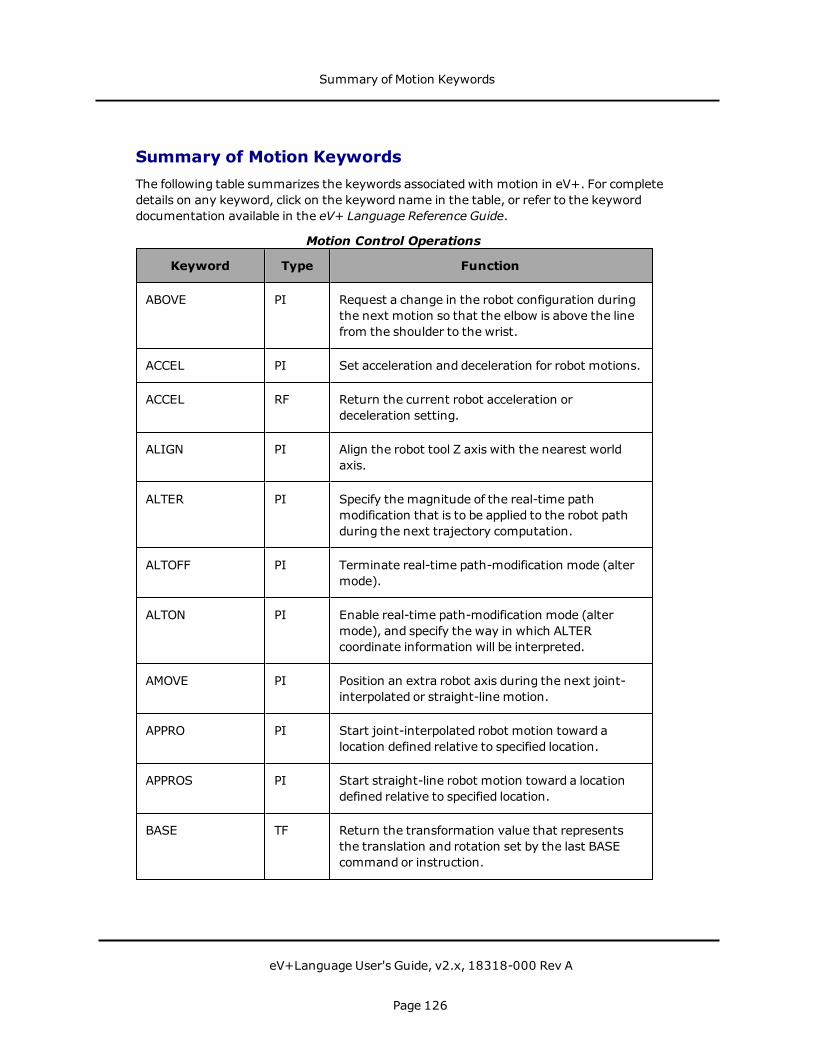
Summary of Motion KeywordsThe following table summarizes the keywords associated with motion in eV+. For completedetails on any keyword, click on the keyword name in the table, or refer to the keyworddocumentation available in the eV+ Language Reference Guide.
Keyword Type Function
ABOVE PI Request a change in the robot configuration duringthe next motion so that the elbow is above the linefrom the shoulder to the wrist.
ACCEL PI Set acceleration and deceleration for robot motions.
ACCEL RF Return the current robot acceleration ordeceleration setting.
ALIGN PI Align the robot tool Z axis with the nearest worldaxis.
ALTER PI Specify the magnitude of the real-time pathmodification that is to be applied to the robot pathduring the next trajectory computation.
ALTOFF PI Terminate real-time path-modification mode (altermode).
ALTON PI Enable real-time path-modification mode (altermode), and specify the way in which ALTERcoordinate information will be interpreted.
AMOVE PI Position an extra robot axis during the next joint-interpolated or straight-line motion.
APPRO PI Start joint-interpolated robot motion toward alocation defined relative to specified location.
APPROS PI Start straight-line robot motion toward a locationdefined relative to specified location.
BASE TF Return the transformation value that representsthe translation and rotation set by the last BASEcommand or instruction.
Motion Control Operations
Summary of Motion Keywords
eV+Language User's Guide, v2.x, 18318-000 Rev A
Page 126
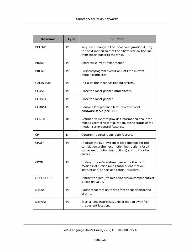
Keyword Type Function
BELOW PI Request a change in the robot configuration duringthe next motion so that the elbow is below the linefrom the shoulder to the wrist.
BRAKE PI Abort the current robot motion.
BREAK PI Suspend program execution until the currentmotion completes.
CALIBRATE PI Initialize the robot positioning system.
CLOSE PI Close the robot gripper immediately.
CLOSEI PI Close the robot gripper.
COARSE PI Enable a low-precision feature of the robothardware servo (see FINE).
CONFIG RF Return a value that provides information about therobot's geometric configuration, or the status of themotion servo-control features.
CP S Control the continuous-path feature.
CPOFF PI Instruct the eV+ system to stop the robot at thecompletion of the next motion instruction (for allsubsequent motion instructions) and null positionerrors.
CPON PI Instruct the eV+ system to execute the nextmotion instruction (or all subsequent motioninstructions) as part of a continuous path.
DECOMPOSE PI Extract the (real) values of individual components ofa location value.
DELAY PI Cause robot motion to stop for the specified periodof time.
DEPART PI Start a joint-interpolated robot motion away fromthe current location.
Summary of Motion Keywords
eV+Language User's Guide, v2.x, 18318-000 Rev A
Page 127
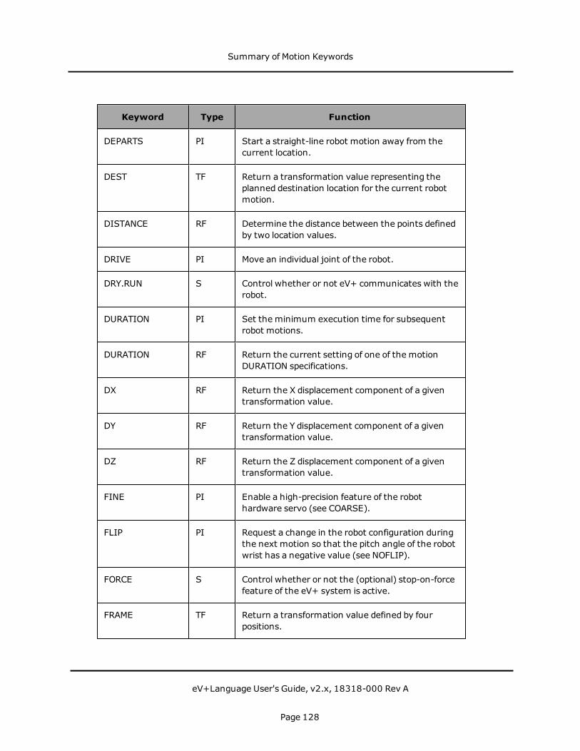
Keyword Type Function
DEPARTS PI Start a straight-line robot motion away from thecurrent location.
DEST TF Return a transformation value representing theplanned destination location for the current robotmotion.
DISTANCE RF Determine the distance between the points definedby two location values.
DRIVE PI Move an individual joint of the robot.
DRY.RUN S Control whether or not eV+ communicates with therobot.
DURATION PI Set the minimum execution time for subsequentrobot motions.
DURATION RF Return the current setting of one of the motionDURATION specifications.
DX RF Return the X displacement component of a giventransformation value.
DY RF Return the Y displacement component of a giventransformation value.
DZ RF Return the Z displacement component of a giventransformation value.
FINE PI Enable a high-precision feature of the robothardware servo (see COARSE).
FLIP PI Request a change in the robot configuration duringthe next motion so that the pitch angle of the robotwrist has a negative value (see NOFLIP).
FORCE S Control whether or not the (optional) stop-on-forcefeature of the eV+ system is active.
FRAME TF Return a transformation value defined by fourpositions.
Summary of Motion Keywords
eV+Language User's Guide, v2.x, 18318-000 Rev A
Page 128
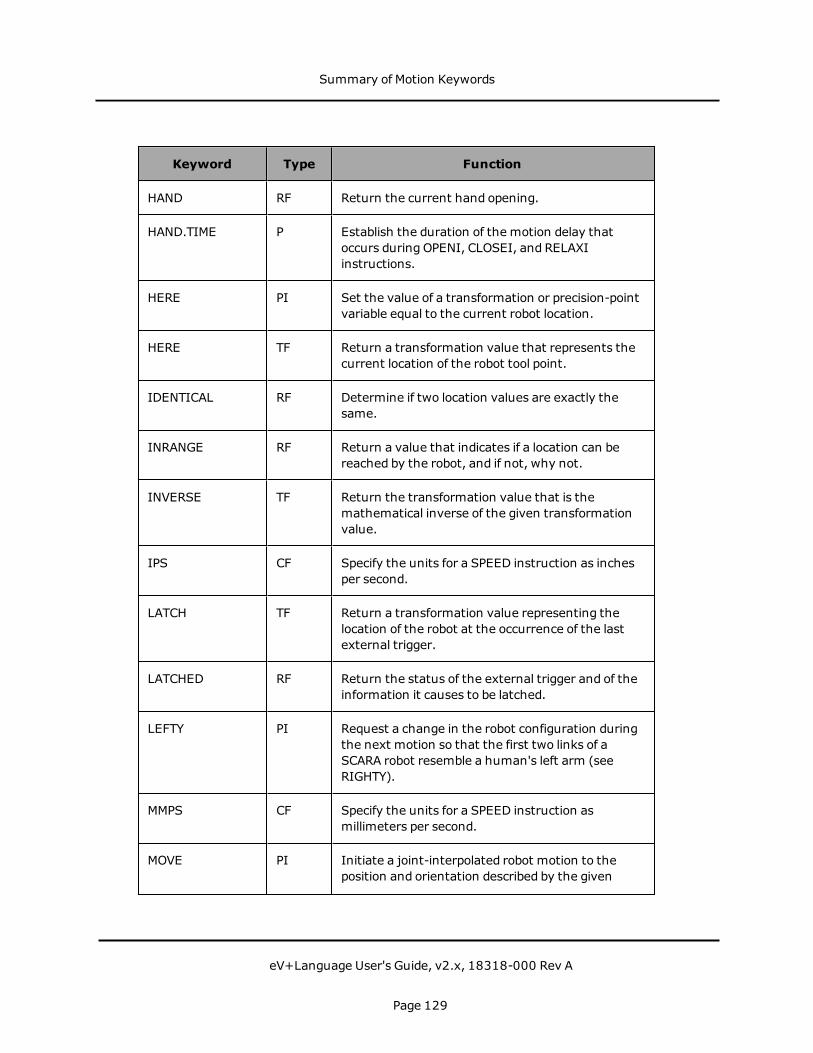
Keyword Type Function
HAND RF Return the current hand opening.
HAND.TIME P Establish the duration of the motion delay thatoccurs during OPENI, CLOSEI, and RELAXIinstructions.
HERE PI Set the value of a transformation or precision-pointvariable equal to the current robot location.
HERE TF Return a transformation value that represents thecurrent location of the robot tool point.
IDENTICAL RF Determine if two location values are exactly thesame.
INRANGE RF Return a value that indicates if a location can bereached by the robot, and if not, why not.
INVERSE TF Return the transformation value that is themathematical inverse of the given transformationvalue.
IPS CF Specify the units for a SPEED instruction as inchesper second.
LATCH TF Return a transformation value representing thelocation of the robot at the occurrence of the lastexternal trigger.
LATCHED RF Return the status of the external trigger and of theinformation it causes to be latched.
LEFTY PI Request a change in the robot configuration duringthe next motion so that the first two links of aSCARA robot resemble a human's left arm (seeRIGHTY).
MMPS CF Specify the units for a SPEED instruction asmillimeters per second.
MOVE PI Initiate a joint-interpolated robot motion to theposition and orientation described by the given
Summary of Motion Keywords
eV+Language User's Guide, v2.x, 18318-000 Rev A
Page 129

Keyword Type Function
location.
MOVES PI Initiate a straight-line robot motion to the positionand orientation described by the given location.
MOVEF PI Initiate a three-segment pick-and-place joint-interpolated robot motion to the specifieddestination, moving the robot at the fastestallowable speed.
MOVESF PI Initiate a three-segment pick-and-place straight-line robot motion to the specified destination,moving the robot at the fastest allowable speed.
MOVET PI Initiate a joint-interpolated robot motion to theposition and orientation described by the givenlocation and simultaneously operate the hand.
MOVEST PI Initiate a straight-line robot motion to the positionand orientation described by the given location andsimultaneously operate the hand.
MULTIPLE PI Allow full rotations of the robot wrist joints (seeSINGLE).
NOFLIP PI Request a change in the robot configuration duringthe next motion so that the pitch angle of the robotwrist has a positive value (see FLIP).
NONULL PI Instruct the eV+ system not to wait for positionerrors to be nulled at the end of continuous-pathmotions (see NULL).
NOOVERLAP PI Disable the NOOVERLAP limit-error checking (seeOVERLAP.)
NORMAL TF Correct a transformation for any mathematicalround-off errors.
NOT.CALIBRATED P Indicate (or assert) the calibration status of therobots connected to the system.
Summary of Motion Keywords
eV+Language User's Guide, v2.x, 18318-000 Rev A
Page 130

Keyword Type Function
NULL TF Return a null transformation value-one with all zerocomponents.
NULL PI Enable nulling of joint position errors.
OPEN PI Open the robot gripper.
OPENI PI Open the robot gripper immediately.
OVERLAP PI Generate a program error if a subsequent motion isplanned that causes a selectedmulti-turn axis tomove more than ±180 degrees to avoid a limit stop(see NOOVERLAP).
#PDEST PF Return a precision-point value representing theplanned destination location for the current robotmotion.
#PHERE PF Return a precision-point value representing thecurrent location of the currently selected robot.
#PLATCH PF Return a precision-point value representing thelocation of the robot at the occurrence of the lastexternal trigger.
POWER S Control or monitor the status of Robot Power.
#PPOINT PF Return a precision-point value composed from thegiven components.
REACTI PI Initiate continuousmonitoring of a specified digitalsignal. Automatically stop the current robot motionif the signal properly transitions and optionallytrigger a subroutine call.
READY PI Move the robot to the READY location above theworkspace, which forces the robot into a standardconfiguration.
RELAX PI Limp the pneumatic hand.
Summary of Motion Keywords
eV+Language User's Guide, v2.x, 18318-000 Rev A
Page 131

Keyword Type Function
RELAXI PI Limp the pneumatic hand immediately.
RIGHTY PI Request a change in the robot configuration duringthe next motion so that the first two links of therobot resemble a human's right arm (see LEFTY).
ROBOT S Enable or disable one robot or all robots.
RX TF Return a transformation describing a rotation aboutthe x axis.
RY TF Return a transformation describing a rotation aboutthe y axis.
RZ TF Return a transformation describing a rotation aboutthe z axis.
SCALE TF Return a transformation value equal to thetransformation parameter with the position scaledby the scale factor.
SCALE.ACCEL S Enable or disable the scaling of acceleration anddeceleration as a function of program speed.
SCALE.ACCEL.ROT S Specify whether or not the SCALE.ACCEL switchtakes into account the Cartesian rotational speedduring straight-line motions.
SELECT PI Select the unit of the named device for access bythe current task.
SELECT RF Return the number of the currently selected unit ofthe named device type.
SET PI Set the value of the location variable on the leftequal to the location value on the right of the equalsign.
SHIFT TF Return a transformation value resulting fromshifting the position of the transformationparameter by the given shift amounts.
Summary of Motion Keywords
eV+Language User's Guide, v2.x, 18318-000 Rev A
Page 132

Keyword Type Function
SINGLE PI Limit rotations of the robot wrist joint to the range -180 degrees to +180 degrees (see MULTIPLE).
SOLVE.ANGLES PI Compute the robot joint positions (for the currentrobot) that are equivalent to a specifiedtransformation.
SOLVE.FLAGS RF Return bit flags representing the robot configurationspecified by an array of joint positions.
SOLVE.TRANS PI Compute the transformation equivalent to a givenset of joint positions for the current robot.
SPEED PI Set the nominal speed for subsequent robotmotions.
SPEED RF Return one of the system motion speed factors.
STATE RF Return a value that provides information about therobot system state.
TOOL PI Set the internal transformation used to representthe location and orientation of the tool tip relative tothe tool mounting flange of the robot.
TOOL TF Return the value of the transformation specified inthe last TOOL command or instruction.
TRANS TF Return a transformation value computed from thegiven X, Y, Z position displacements and y, p, rorientation rotations.
PI: Program Instruction, RF: Real-Valued Function, TF: Transformation Function, S:Switch, P: Parameter, PF: Precision-Point Function, CF: Conversion Factor
Summary of Motion Keywords
eV+Language User's Guide, v2.x, 18318-000 Rev A
Page 133


Input/Output OperationsThe following topics are described in this chapter:
Digital I/O 137Serial and Disk I/O Basics 139Disk I/O 143Advanced Disk Operations 148Serial Line I/O 152DeviceNet 156Summary of I/O Operations 157
Input/Output Operations
eV+Language User's Guide, v2.x, 18318-000 Rev A
Page 135

Input/Output Operations
eV+Language User's Guide, v2.x, 18318-000 Rev A
Page 136

Digital I/OOmron Adept controllers can communicate in a digital fashion with external devices usingthe Digital I/O capability. Digital input reads the status of a signal controlled by user-installedequipment. A typical digital input operation is to wait for a microswitch on a workcellconveyor to close, indicating that an assembly is in the proper place. The WAIT instructionand SIG function are used to halt program execution until a digital input channel signalachieves a specified state. The program line:
WAIT SIG(1001)
halts program execution until a switching device attached to digital input channel 1001 isclosed. If signal 1002 is a sensor indicating a part feeder is empty, the code:
IF SIG(1002) THENCALL service.feeder()
END
checks the sensor state and calls a routine to service the feeder if the sensor is on.
The SIGNAL instruction is used for digital output. In the above example, the conveyor beltmay need to be stopped after digital input signal 1001 signals that a part is in place. Theinstruction:
SIGNAL(-33)
turns off digital output signal 33, causing the conveyor belt connected to signal 33 to stop.When processing on the part is finished and the part needs to be moved out of the work area,the instruction:
SIGNAL(33)
turns the conveyor belt back on. The digital I/O channels must be installed before they canbe accessed by the SIG function or SIGNAL instruction. The SIG.INS function returns anindication of whether a given signal number is available. The code line:
IF SIG.INS(33) THEN
can be used to ensure that a digital signal is available before you attempt to access it. Themonitor command IO displays the status of all digital I/O channels. For details on installingdigital I/O hardware, see the SmartController EX User's Guide.
Digital output channels are numbered from 1 to 512. Input channels are in the range 1001to 1512. Multiple signals can be turned ON or OFF with a single instruction.
SIGNAL(33),(-34),(35)or
SIGNAL(-33),(34),(-35)
Digital I/O
eV+Language User's Guide, v2.x, 18318-000 Rev A
Page 137
High-Speed Interrupts
Normally, the digital I/O system is checked once every eV+ major cycle (every 16 ms). Insome cases, the delay or uncertainty resultingmay be unacceptable. Digital signals 1001 -1004 can be configured as high-speed interrupts. When a signal configured as a high-speedinterrupt transitions, its state is read at system interrupt level, resulting in a maximum delayof 1 ms. The ACE software Controller Configuration Tools are used to configure high-speedinterrupts.
Soft Signals
Soft signals are used primarily as global flags. The soft signals are in the range 2001 - 2512and can be usedwith SIG and SIGNAL. A typical use of soft signals is for intertaskcommunication. See "REACT and REACTI" and the REACT_ instructions in the eV+ LanguageReference Guide.
Digital I/O and Third Party Boards
When eV+ starts, default blocks of system memory are assigned to the digital I/O system.eV+ expects to find the digital I/O image at these locations. If you are using a third partydigital I/O board, you must remap these memory locations to correspond to the actualmemory location of the digital I/O image on your board. See the description of DEF.DIO in theeV+ Language Reference Guide for details.
Digital I/O and DeviceNet
When eV+ starts, default blocks of system memory are assigned to the DeviceNet system.eV+ expects to find the DeviceNet image at these locations. For additional information, seeDeviceNet on page 156.
Digital I/O
eV+Language User's Guide, v2.x, 18318-000 Rev A
Page 138

Serial and Disk I/O BasicsThe following sections describe the basic procedures that are common to both serial and diskI/O operations. Disk I/O on page 143 covers disk I/O in detail. Serial Line I/O on page 152covers serial I/O in detail.
Logical Units
All eV+ serial and disk I/O operations reference an integer value called a Logical Unit Numberor LUN. The LUN provides a shorthandmethod of identifying which device or file is beingreferenced by an I/O operation. See the ATTACH command in the eV+ Language ReferenceGuide for the default device LUN numbers.
Disk devices are different from all the other devices in that they allow files to be opened. Eachprogram task can have one file open on each disk LUN. That is, each program task can havemultiple files open simultaneously (on the same or different disk units).
NOTE: Nomore than 60 disk files can be open by the entire system at any time. Thatincludes files opened by programs and by the system monitor (for example, for the FCOPYcommand). The error *Device not ready* results if an attempt is made to open a 61st file.
For details on accessing the graphics window LUNs, see Graphics Programming on page 161.
Error Status
Unlike most other eV+ instructions, I/O operations are expected to fail under certaincircumstances. For example, when reading a file, an error status is returned to the programto indicate when the end of the file is reached. The program is expected to handle this errorand continue execution. Similarly, a serial line may return an indication of a parity error,which should cause the program to retry a data transmission sequence.
For these reasons, eV+ I/O instructions normally do not stop program execution when anerror occurs. Instead, the success or failure of the operation is saved internally for access bythe IOSTAT real-valued function. For example, a reference to IOSTAT(5) returns a valueindicating the status of the last I/O operation performed on LUN 5. The values returned byIOSTAT fall into one of following three categories:
Value Explanation
1 The I/O operation completed successfully.
0 The I/O operation has not yet completed. This value appears only if apre-read or no-wait I/O is being performed.
<0 The I/O operation completed with an error. The error code indicates
IOSTAT Return Values
Serial and Disk I/O Basics
eV+Language User's Guide, v2.x, 18318-000 Rev A
Page 139
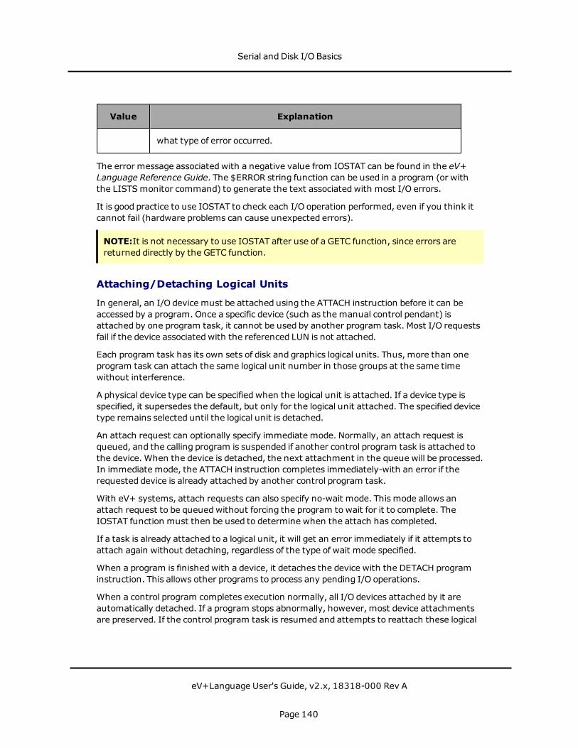
Value Explanation
what type of error occurred.
The error message associated with a negative value from IOSTAT can be found in the eV+Language Reference Guide. The $ERROR string function can be used in a program (or withthe LISTSmonitor command) to generate the text associated with most I/O errors.
It is good practice to use IOSTAT to check each I/O operation performed, even if you think itcannot fail (hardware problems can cause unexpected errors).
NOTE:It is not necessary to use IOSTAT after use of a GETC function, since errors arereturned directly by the GETC function.
Attaching/Detaching Logical Units
In general, an I/O device must be attached using the ATTACH instruction before it can beaccessed by a program. Once a specific device (such as the manual control pendant) isattached by one program task, it cannot be used by another program task. Most I/O requestsfail if the device associated with the referenced LUN is not attached.
Each program task has its own sets of disk and graphics logical units. Thus, more than oneprogram task can attach the same logical unit number in those groups at the same timewithout interference.
A physical device type can be specified when the logical unit is attached. If a device type isspecified, it supersedes the default, but only for the logical unit attached. The specified devicetype remains selected until the logical unit is detached.
An attach request can optionally specify immediate mode. Normally, an attach request isqueued, and the calling program is suspended if another control program task is attached tothe device. When the device is detached, the next attachment in the queue will be processed.In immediate mode, the ATTACH instruction completes immediately-with an error if therequested device is already attached by another control program task.
With eV+ systems, attach requests can also specify no-wait mode. This mode allows anattach request to be queuedwithout forcing the program to wait for it to complete. TheIOSTAT function must then be used to determine when the attach has completed.
If a task is already attached to a logical unit, it will get an error immediately if it attempts toattach again without detaching, regardless of the type of wait mode specified.
When a program is finishedwith a device, it detaches the device with the DETACH programinstruction. This allows other programs to process any pending I/O operations.
When a control program completes execution normally, all I/O devices attached by it areautomatically detached. If a program stops abnormally, however, most device attachmentsare preserved. If the control program task is resumed and attempts to reattach these logical
Serial and Disk I/O Basics
eV+Language User's Guide, v2.x, 18318-000 Rev A
Page 140

units, it may fail because of the attachments still in effect. The KILL monitor commandforces a program to detach all the devices it has attached.
If attached by a program, the terminal andmanual control pendant are detachedwheneverthe program halts or pauses for any reason, including error conditions and single-stepmode.If the program is resumed, the terminal and the manual control pendant are automaticallyreattached if they were attached before the termination.
NOTE: It is possible that another program task could have attached the terminal ormanual control pendant. That would result in an error message when the stopped task isrestarted.
Reading
The READ instruction processes input from all devices. The basic READ instruction issues arequest to the device attached on the indicated LUN andwaits until a complete data record isreceived before program execution continues. (The length of the last record read can beobtainedwith the IOSTAT function with its second argument set to 2.)
The GETC real-valued function returns the next data byte from an I/O device without waitingfor a complete data record. It is commonly used to read data from the serial lines or thesystem terminal. It also can be used to read disk files in a byte-by-byte manner.
Special mode bits to allow reading with no echo are supported for terminal read operations.Terminal input also can be performed using the PROMPT instruction.
The GETEVENT instruction can be used to read input from the system terminal. This may beuseful in writing programs that operate on both graphics and nongraphics-based systems.
To read data from a disk device, a file must be open on the corresponding logical unit. TheFOPEN_ instructions open disk files.
Writing
TheWRITE instruction processes output to serial and disk devices and to the terminal. Thebasic WRITE instruction issues a request to the device attached on the indicated LUN, andwaits until the complete data record is output before program execution continues.
WRITE instructions accept format control specifiers that determine how output data isformatted, andwhether or not an end of recordmark should be written at the end of therecord.
Terminal output also can be performed using the PROMPT or TYPE instructions.
A file must be open using the FOPENW or FOPENA instructions before data can be written toa disk device. FOPENW opens a new file. FOPENA opens an existing file and appends data tothat file.
Serial and Disk I/O Basics
eV+Language User's Guide, v2.x, 18318-000 Rev A
Page 141
Input Wait Modes
Normally, eV+ waits until the data from an input instruction is available before continuingwith program execution. However, the READ instruction and GETC function accept anoptional argument that specifies no-wait mode. In no-wait mode, these instructions returnimmediately with the error status -526 (No data received) if there is no data available. Aprogram can loop and use these operations repeatedly until a successful read is completed oruntil some other error is received.
The disk devices do not recognize no-wait mode on input and treat such requests as normalinput-with-wait requests.
Output Wait Modes
Normally, eV+ waits for each I/O operation to be completed before continuing to the nextprogram instruction. For example, the instruction:
TYPE /X50
causes eV+ to wait for the entire record of 50 spaces to be transmitted (about 50 millisecondswith the terminal set to 9600 baud) before continuing to the next program instruction.
Similarly, WRITE instructions to serial lines or disk files will wait for any required physicaloutput to complete before continuing.
This waiting is not performed if the /N (no wait) format control is specified in an outputinstruction. Instead, eV+ immediately executes the next instruction. The IOSTAT functionchecks whether or not the output has completed. It returns a value of zero if the previous I/Ois not complete.
If a second output instruction for a particular LUN is encountered before the first no-waitoperation has completed, the second instruction automatically waits until the first is done.This schememeans the no-wait output is effectively double-buffered. If an error occurs in thefirst operation, the second operation is canceled, and the IOSTAT value is correct for the firstoperation.
With eV+, the IOSTAT function can be usedwith a second argument of 3 to explicitly checkfor the completion of a no-wait write.
Serial and Disk I/O Basics
eV+Language User's Guide, v2.x, 18318-000 Rev A
Page 142

Disk I/O
NOTE: The ACE software provides the following functionality through its graphical userinterface. Therefore, Omron Adept strongly recommends that you use the ACE software.
The following sections discuss disk I/O.
Attaching Disk Devices
A disk LUN refers to a local disk device, such as the SDI card in a SmartController EX system.Also, a remote disk may be accessed via a network.
The type of device to be accessed is determined by the DEFAULT command or the ATTACHinstruction. If the default device type set by the DEFAULT command is not appropriate at aparticular time, the ATTACH instruction can be used to override the default. The syntax ofthe ATTACH instruction is:
ATTACH (lun, mode) $device
See the documentation for the ATTACH program instruction for the mode options andpossible device names. The instruction:
ATTACH (dlun, 4) "DISK"
attaches to an available disk logical unit and returns the number of the logical unit in thevariable dlun, which can then be used in other disk I/O instructions.
If the device name is omitted from the instruction, the default device for the specified LUN isused. Omron Adept recommends that you always specify a device name with the ATTACHinstruction. (The device SYSTEM refers to the device specified with the DEFAULTmonitorcommand.)
Once the attachment is made, the device cannot be changed until the logical unit isdetached. However, any of the units available on the device can be specified when opening afile. For example, the eV+ DISK units are A, C and D. After attaching a DISK device LUN, aprogram can open and close files on either of these disk units before detaching the LUN.
Disk I/O and the Network File System (NFS)
In addition to local disk devices, an Omron Adept system equippedwith Ethernet hardwareand the TCP/IP license can access remote disk drives in the same fashion as local disks.
The following sections describe accessing a disk drive regardless of whether it is a local driveor a remotely-accessed drive.
Disk Directories
The FOPEN_ instructions, which open disk files for reading andwriting, use directory paths inthe same fashion as the monitor commands LOAD, STORE, etc. Files on a disk are grouped in
Disk I/O
eV+Language User's Guide, v2.x, 18318-000 Rev A
Page 143
directories. If a disk is thought of as a file cabinet, then a directory can be thought of as adrawer in that cabinet. Directories allow files (the file folders in our file cabinet analogy) thathave some relationship to each other to be grouped together and separated from other files.See the chapter Using Files in the eV+ Operating System User's Guide for more details on thedirectory structure.
Disk File Operations
All I/O requests to a disk device are made to a file on that device. A disk file is a logicalcollection of data records1 on a disk. Each disk file has a name, and all the names on a disk arestored in a directory on the disk. The FDIRECTORYmonitor command displays the names ofthe files on a disk.
A disk file can be accessed either sequentially, where data records are accessed from thebeginning of the file to its end, or randomly, where data records are accessed in any order.Sequential access is simplest and is assumed in this section. Random access is described laterin this chapter.
Opening a Disk File
Before a disk file can be opened, the disk the file is on must be ATTACHed.
The FOPEN_ instructions open disk files (and file directories). These instructions associate aLUN with a disk file. Once a file is open, the READ, GETC, andWRITE instructions access thefile. These instructions use the assigned LUN to access the file so that multiple files may beopen on the same disk and the I/O operations for the different disk files will not affect eachother.2
The simplified syntax for FOPEN_ is:
FOPEN_ (lun)file_spec
where:
lun logical unit number used in the ATTACH instruction
file_spec file specification in the form, unit:path\filename.ext
unit is an optional disk unit name. The standard local diskunits are A, C, and D. If no unit is specified, the colonalso must be omitted. Then the default unit (asdetermined by the DEFAULT command) is assumed.
path\ is an optional directory path string. The directory pathis defined by one or more directory names, eachfollowed by a \ character. The actual directory path isdetermined by combining any specified path with thepath set by the DEFAULT command. If path is
Disk I/O
eV+Language User's Guide, v2.x, 18318-000 Rev A
Page 144
precededwith a \, the path is absolute. Otherwise, thepath is relative and is added to the current DEFAULTpath specification. (If unit is specified and is differentfrom the default unit, the path is always absolute.)
filename is a name with 1 to 8 characters, which is used as thename of the file on the disk.
ext is the filename extension-a string with 0 to 3characters, which is used to identify the file type.
The four open commands are:
1. Open for read only (FOPENR). If the disk file does not exist, an error is returned. Nowrite operations are allowed, so data in the file cannot be modified.
2. Open for write (FOPENW). If the disk file already exists, an error is returned.Otherwise, a new file is created. Both read andwrite operations are allowed.
3. Open for append (FOPENA). If the disk file does not exist, a new file is created.Otherwise, an existing file is opened. No error is returned in either case. A sequentialwrite or a random write with a zero record number appends data to the end of the file.
4. Open for directory read (FOPEND). The last directory in the specified directory path isopened. Only read operations are allowed. Each record read returns an ASCII stringcontaining directory information. Directories should be opened using variable-lengthsequential-access mode.
While a file is open for write or append access, another control program task cannot accessthat file. However, multiple control program tasks can access a file simultaneously in read-only mode.
Writing to a Disk
The instruction:
WRITE (dlun) $in.string
writes the string stored in $in.string to the disk file open on dlun. The instruction:
error = IOSTAT(dlun)
returns any errors generated during the write operation.
Reading From a Disk
The instruction:
READ (dlun) $in.string
Disk I/O
eV+Language User's Guide, v2.x, 18318-000 Rev A
Page 145

reads (from the open file on dlun) up to the first CR/LF (or end of file if it is encountered) andstore the result in $in.string. When the end of file is reached, eV+ error number -504Unexpected end of file is generated. The IOSTAT() function must be used to recognize thiserror and halt reading of the file:
DOREAD (dlun) $in.stringTYPE $in.string
UNTIL IOSTAT(dlun) == -504
The GETC function reads the file byte by byte if you want to examine individual bytes fromthe file (or if the file is not delimited by CR/LFs).
Detaching
When a disk logical unit is detached, any disk file that was open on that unit is automaticallyclosed. However, error conditions detected by the close operation may not be reported.Therefore, it is good practice to use the FCLOSE instruction to close files and to check theerror status afterwards. FCLOSE ensures that all buffered data for the file is written to thedisk, and updates the disk directory to reflect any changesmade to the file. The DETACHinstruction frees up the logical unit. The following instructions close a file and detach a diskLUN:
FCLOSE (dlun)IF IOSTAT(dlun) THEN
TYPE $ERROR(IOSTAT(dlun))END
DETACH (dlun)
When a program completes normally, any open disk files are automatically closed. If aprogram stops abnormally and execution does not proceed, the KILL monitor commandcloses any files left open by the program.
CAUTION: While a file is open on a floppy disk, do not replace thefloppy disk with another disk: Data may be lost and the new disk maybe corrupted.
Disk I/O Example
The following example creates a disk file, writes to the file, closes the file, reopens the file, andreads back its contents.
AUTO dlun, iAUTO $file.name$file.name = "data.tst"
; Attach to a disk logical unitATTACH (dlun, 4) "DISK"
Disk I/O
eV+Language User's Guide, v2.x, 18318-000 Rev A
Page 146

IF IOSTAT(dlun) < 0 GOTO 100
; Open a new file and check statusFOPENW (dlun) $file.nameIF IOSTAT(dlun) < 0 GOTO 100
; Write the textFOR i = 1 TO 10
WRITE (dlun) "Line "+$ENCODE(i)IF IOSTAT(dlun) < 0 GOTO 100
END
; Close the fileFCLOSE (dlun)IF IOSTAT(dlun) < 0 GOTO 100
; Reopen the file and read its contentsFOPENR (dlun) $file.nameIF IOSTAT(dlun) < 0 GOTO 100READ (dlun) $txtWHILE IOSTAT(dlun) > 0 DO
TYPE $txtREAD (dlun) $txt
END ;End of file or errorIF (IOSTAT(dlun) < 0) AND (IOSTAT(dlun) <> -504) THEN
100 TYPE $ERROR(IOSTAT(dlun)) ;Report any errorsENDFCLOSE (dlun) ;Close the fileIF IOSTAT(dlun) < 0 THEN
TYPE $ERROR(IOSTAT(dlun))ENDDETACH (dlun) ;Detach the LUN
1A variable-length record is a text string terminated by a CR/LF (ASCII 13/ASCII 10).
2When accessing files on a remote system, the unit can be any name string, and the filename and extension can be any arbitrary string of characters.
Disk I/O
eV+Language User's Guide, v2.x, 18318-000 Rev A
Page 147

Advanced Disk OperationsThis section introduces additional parameters to the FOPEN and FOPENR programinstructions. For details, see the FOPEN and FOPENR documentation in the eV+ LanguageReference Guide for details.
Variable-Length Records
The default disk file access mode is variable-length recordmode. In this mode, records canhave any length (up to a maximum of 512 bytes) and can cross the boundaries of 512-bytesectors. The end of a record is indicated by a Line-Feed character (ASCII 10). Also, the end ofthe file is indicated by the presence of a Ctrl+Z character (26 decimal) in the file. Variable-length records should not contain any internal Line-Feed or Ctrl+Z characters as data. Thisformat is used for loading and storing eV+ programs, and is compatible with the IBM PCstandard ASCII file format.
Variable-length recordmode is selected by setting the record length parameter in theFOPEN_ instruction to zero, or by omitting the parameter completely. In this mode,WRITEinstructions automatically append Return (ASCII 13) and Line-Feed characters to the outputdata-which makes it a complete record. If the /S format control is specified in an outputspecification, no Return/Line-Feed is appended. Then any subsequent WRITE will have itsdata concatenated to the current data as part of the same record. If the /Cn format control isspecified, n Return/Line-Feeds are written, creatingmultiple records with a single WRITE.
When a variable-length record is read using a READ instruction, the Return/Line-Feedsequence at the end is removed before returning the data to the eV+ program. If the GETCfunction is used to read from a disk file, all characters are returned as they appear in the file-including Return, Line-Feed, and Ctrl+Z characters.
Fixed-Length Records
In fixed-length recordmode, all records in the disk file have the same specific length. Thenthere are no special characters embedded in the file to indicate where records begin or end.Records are contiguous andmay freely cross the boundaries of 512-byte sectors.
Fixed-length recordmode is selected by setting the record length parameter in the FOPEN_instruction to the size of the record, in bytes. WRITE instructions then pad data records withzero bytes or truncate records as necessary to make the record length the size specified. Noother data bytes are appended, and the /S format control has no effect.
In fixed-length mode, READ instructions always return records of the specified length. If thelength of the file is such that it cannot be divided into an even number of records, a READ ofthe last record will be paddedwith zero bytes to make it the correct length.
Sequential-Access Files
Normally, the records within a disk file are accessed in order from the beginning to the endwithout skipping any records. Such files are called sequential files. Sequential-access files
Advanced Disk Operations
eV+Language User's Guide, v2.x, 18318-000 Rev A
Page 148

may contain either variable-length or fixed-length records.
Random-Access Files
In some applications, disk files need to be read or written in a nonsequential or randomorder. eV+ supports random access only for files with fixed-length records. Records arenumbered starting with 1. The position of the first byte in a random-access record can becomputed by:
byte_position = 1 + (record_number -1) * record_length
Random access is selected by setting the random-access bit in the mode parameter of theFOPEN_ instruction. A nonzero record length must also be specified.
A specific record is accessed by specifying the record number in a READ or WRITE instruction.If the record number is omitted, or is zero, the record following the one last accessed is used.(See the FOPEN documentation.)
Buffering and I/O Overlapping
All physical disk I/O occurs as 512-byte sector reads andwrites. Records are unpacked fromthe sector buffer on input, and additional sectors are read as needed to complete a record. Tospeed up read operations, eV+ automatically issues a read request for the next sector whileit is processing the current sector. This request is called a preread. Preread is selected bydefault for both sequential-access and random-access modes. It can be disabled by setting abit in the mode parameter of the FOPEN_ instruction. If prereads are enabled, opening a filefor read access immediately issues a read for the first sector in the file.
Preread operations may actually degrade system performance if records are accessed in trulyrandom order, since sectors would be read that would never be used. In this case, prereadsshould be disabled and the FSEEK instruction should be used to initiate a preread of the nextrecord to be used.
The function IOSTAT(lun, 1) returns the completion status for a pending preread or FSEEKoperation.
On output, records are packed into sector buffers andwritten after the buffers are filled. Ifno-wait mode is selected for a write operation by using the /N format control, the WRITEinstruction does not wait for a sector to be written before allowing program execution tocontinue.
In random-access mode, a sector buffer is not normally written to disk until a record notcontained in that buffer is accessed. The FEMPTY instruction empties the current sectorbuffer by immediately writing it to the disk.
A file may be opened in nonbufferedmode, which ismuch slower than normal bufferedmode, but it guarantees that information that is written will not be lost due to a systemcrash or power failure. This mode was intended primarily for use with log files that are left
Advanced Disk Operations
eV+Language User's Guide, v2.x, 18318-000 Rev A
Page 149

opened over an extended period of time and intermittently updated. For these types of files,the additional (significant) overhead of this mode is not as important as the benefit.
When a file is being created, information about the file size is not stored in the disk directoryuntil the file is closed. Closing a file also forces any partial sector buffers to be written to thedisk. Note that aborting a program does not force files associated with it to be closed. The filesare not closed (and the directory is not updated) until a KILL command is executed or untilthe aborted program is executed again.
Disk Commands
There are several disk-orientedmonitor commands that do not have a correspondingprogram instruction. The FCMND instruction must be used to perform the following actionsfrom within a program:
l Rename a file
l Format a disk
l Create a subdirectory
l Delete a subdirectory
The MCS instruction can be used to issue an FCOPY command from within a program.
FCMND is similar to other disk I/O instructions in that a logical unit must be attached and thesuccess or failure of the command is returned via the IOSTAT real-valued function. Fordetails, see the documentation for the FCMND program instruction.
The FCMND instruction is described in detail in the eV+ Language Reference Guide. See theMV Controller User's Guide
Accessing the Disk Directories
The eV+ directory structure is identical to that used by the IBM PC DOS operating system(version 2.0 and later). For each file, the directory structure contains the file name,attributes, creation time and date, and file size. Directory entries may be read aftersuccessfully executing an FOPEND instruction.
Each directory record returned by a READ instruction contains an ASCII string with theinformation shown in the following table.
Byte Size Description
1-7 7 Attribute codes, paddedwith blanks onright
Disk Directory Format
Advanced Disk Operations
eV+Language User's Guide, v2.x, 18318-000 Rev A
Page 150
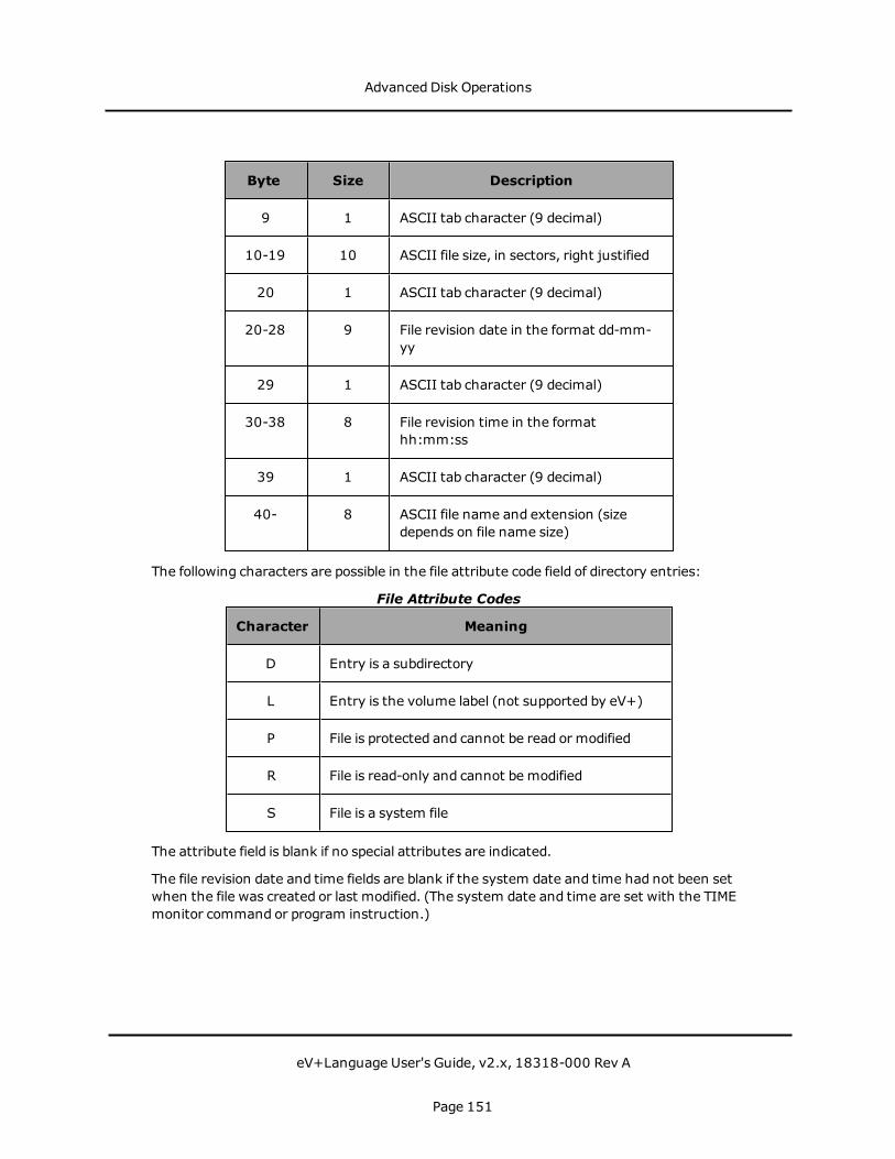
Byte Size Description
9 1 ASCII tab character (9 decimal)
10-19 10 ASCII file size, in sectors, right justified
20 1 ASCII tab character (9 decimal)
20-28 9 File revision date in the format dd-mm-yy
29 1 ASCII tab character (9 decimal)
30-38 8 File revision time in the formathh:mm:ss
39 1 ASCII tab character (9 decimal)
40- 8 ASCII file name and extension (sizedepends on file name size)
The following characters are possible in the file attribute code field of directory entries:
Character Meaning
D Entry is a subdirectory
L Entry is the volume label (not supported by eV+)
P File is protected and cannot be read or modified
R File is read-only and cannot be modified
S File is a system file
File Attribute Codes
The attribute field is blank if no special attributes are indicated.
The file revision date and time fields are blank if the system date and time had not been setwhen the file was created or last modified. (The system date and time are set with the TIMEmonitor command or program instruction.)
Advanced Disk Operations
eV+Language User's Guide, v2.x, 18318-000 Rev A
Page 151

Serial Line I/OThe eV+ controller has several serial lines that are available for general use. This sectiondescribes how these lines are used for simple serial communications.
I/O Configuration
In addition to selecting the protocol to be used, the controller configuration program allowsthe baud rate and byte format for each serial line to be defined. Once the serial lineconfiguration is defined on the eV+ system boot disk, the serial lines are set up automaticallywhen the eV+ system is loaded and initialized. The following byte formats are available:
l Byte data length of 7 or 8 bits, not including parity
l One or two stop bits
l Parity disabled or enabled
l Odd or even parity (adds 1 bit to byte length)
The following baud rates are available:
110, 300, 600, 1200, 2400, 4800, 7200, 9600, 19200, 38400
In addition, eV+ provides automatic buffering with optional flow control for each serial line.The I/O configuration program can be used to enable output flow control with which eV+recognizes Ctrl+S (19 decimal) and Ctrl+Q (17 decimal) and uses them to suspend andresume, respectively, serial line output. The configuration program can also enable input flowcontrol, with which eV+ generates Ctrl+S and Ctrl+Q to suspend and resume, respectively,input from an external source. With Ctrl+S and Ctrl+Q flow control disabled, all input andoutput is totally transparent, and all 8-bit data bytes can be sent and received.
Serial lines may also be configured to use hardware modem control lines for flow control. (TheRTS/CTS lines must be installed in the modem cable-standardmodem cables often leavethese lines out.) For pin assignments, see the documentation on serial I/O connectors in theSmartController EX User's Guide.
Attaching/Detaching Serial I/O Lines
Serial lines must be attached before any I/O operations can take place. Note that only onecontrol program task can be attached to a single serial line at any one time. All otherattachment requests will queue or fail, depending on the setting of the mode parameter inthe ATTACH program instructions.
Attaching or detaching a serial line automatically stops any output in progress and clears allinput buffers. Serial lines are not automatically detached from a program unless it completeswith success, so it is possible to single-step through a program or proceed from a PAUSEinstruction without loss of data.
Serial Line I/O
eV+Language User's Guide, v2.x, 18318-000 Rev A
Page 152

Input Processing
Input data is received by eV+ according to the byte format specified by the I/O configurationprogram. The size of the buffer can be set with the ACE software Controller ConfigurationTools. Data errors such as parity or framing errors are also buffered and are returned in theproper order.
The possible data errors from the serial input lines are:
-522 *Data error on device*
A data byte was receivedwith incorrect parity, or the byte generated aframing error.
-524 *Communications overrun*
Data bytes were received after the input buffer was full, or faster thaneV+ could process them.
-526 *No data received*
If data is expected, continue polling the serial line.
-504 *Unexpected end of file*
A BREAKwas received from the remote device.
Serial line input data is normally read using the GETC function, since it allows the mostflexible response to communications errors. The READ instruction also can be used providedthat input data is terminated by a Line-Feed character (10 decimal).
eV+ does not support input echoing or input line editing for the serial lines.
Output Processing
All serial line output is performed using the WRITE instruction. All binary data (includingNULL characters) is output without conversion. If the serial line is configured to supportparity, a parity bit is automatically appended to each data byte.
By default, the WRITE instruction appends a Return character (13 decimal) and a Line-Feedcharacter (10 decimal) to each data record unless the /S format control is specified in theinstruction parameter list.
If output flow control is enabled and output has been suspended by a Ctrl+S character fromthe remote device, a WRITE request may wait indefinitely before completing.
Serial I/O Examples
The first example attaches to a serial line and performs simple WRITEs and READs on theline:
Serial Line I/O
eV+Language User's Guide, v2.x, 18318-000 Rev A
Page 153

.PROGRAM serial.io(); ABSTRACT: Example program to write and read lines of; text to and from serial port 1 on the SIO module.
AUTO slun ;Logical unit to communicate to serial portAUTO $text
; Attach to a logical unit(open communications path; to serial port)
ATTACH (slun, 4) "SERIAL:1"IF IOSTAT(slun) < 0 GOTO 100
; Write text out to the serial port
WRITE (slun) "Hello there! "IF IOSTAT(slun) < 0 GOTO 100
; Read a line of text from the serial port. The incoming; line of text must be terminated by a carriage return and; line feed. The READ instruction will wait until a line of; text is received.
READ (slun) $textIF IOSTAT(slun) < 0 GOTO 100
; Display any errors
100 IF (IOSTAT(slun) < 0) THENTYPE IOSTAT(slun), " ", $ERROR(IOSTAT(slun))
END
DETACH (slun) ;Detach from logical unit.END
The next example reads data from a serial line using the GETC function with no-wait mode.Records that are received are displayed on the terminal. In this program, data records on theserial line are assumed to be terminated by an ETX character, which is not displayed. Anempty record terminates the program.
.PROGRAM display(); ABSTRACT: Monitor a serial line and read data when; available
AUTO $buffer, c, done, etx, ienod, lineetx = 3 ;ASCII code for ETX characterienod = -526 ;Error code for no dataATTACH (line, 4) "SERIAL:1"IF IOSTAT(line) < 0 GOTO 90 ;Check for errors$buffer = "" ;Initialize buffer to emptydone = FALSE ;Assert not doneDO
CLEAR.EVENTc = GETC(line,1) ;Read byte from the ser. line
Serial Line I/O
eV+Language User's Guide, v2.x, 18318-000 Rev A
Page 154

WHILE c == ienod DO ;While there is no data...WAIT.EVENT 1 ;Wait for an eventCLEAR.EVENTc = GETC(line,1) ;Read byte from the ser. line
ENDIF c < 0 GOTO 90 ;Check for errorsIF c == etx THEN ;If ETX seen...
TYPE $buffer, /N ;Type bufferdone = (LEN($buffer) == 0) ;Done if buffer length is 0$buffer = "" ;Set buffer to empty
ELSE$buffer = $buffer+$CHR(c) ;Append next byte
;to buffer
ENDUNTIL done ;Loop until empty buffer seen
GOTO 100 ;Exit90 TYPE "SERIAL LINE I/O ERROR: ", $ERROR(IOSTAT(line))
PAUSE100 DETACH (line)
RETURN.END
Serial Line I/O
eV+Language User's Guide, v2.x, 18318-000 Rev A
Page 155
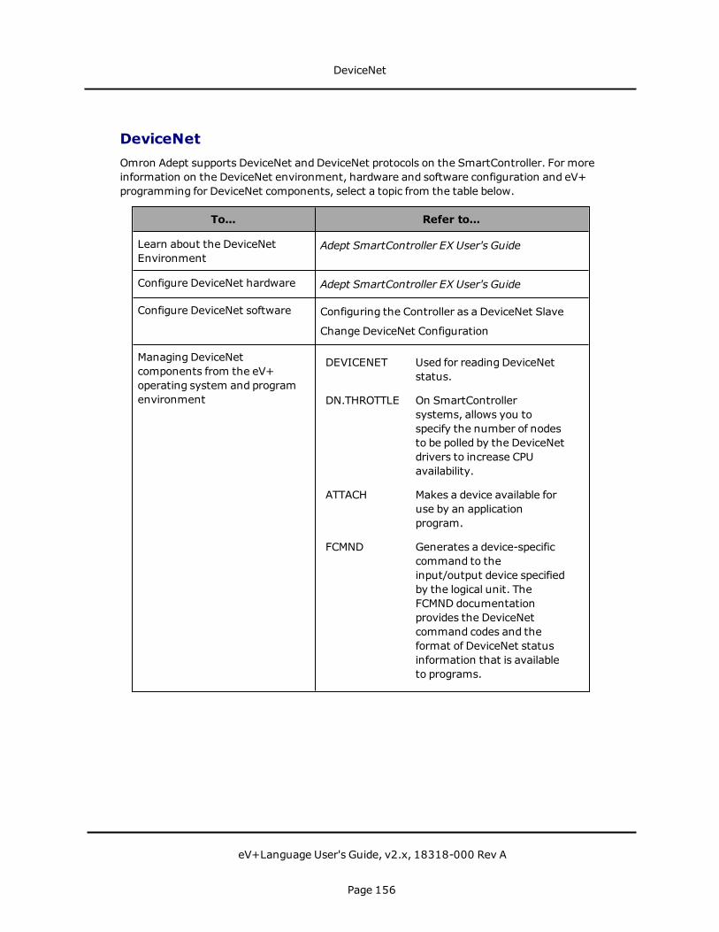
DeviceNetOmron Adept supports DeviceNet and DeviceNet protocols on the SmartController. For moreinformation on the DeviceNet environment, hardware and software configuration and eV+programming for DeviceNet components, select a topic from the table below.
To... Refer to...
Learn about the DeviceNetEnvironment
Adept SmartController EX User's Guide
Configure DeviceNet hardware Adept SmartController EX User's Guide
Configure DeviceNet software Configuring the Controller as a DeviceNet Slave
Change DeviceNet Configuration
Managing DeviceNetcomponents from the eV+operating system and programenvironment
DEVICENET Used for reading DeviceNetstatus.
DN.THROTTLE On SmartControllersystems, allows you tospecify the number of nodesto be polled by the DeviceNetdrivers to increase CPUavailability.
ATTACH Makes a device available foruse by an applicationprogram.
FCMND Generates a device-specificcommand to theinput/output device specifiedby the logical unit. TheFCMND documentationprovides the DeviceNetcommand codes and theformat of DeviceNet statusinformation that is availableto programs.
DeviceNet
eV+Language User's Guide, v2.x, 18318-000 Rev A
Page 156
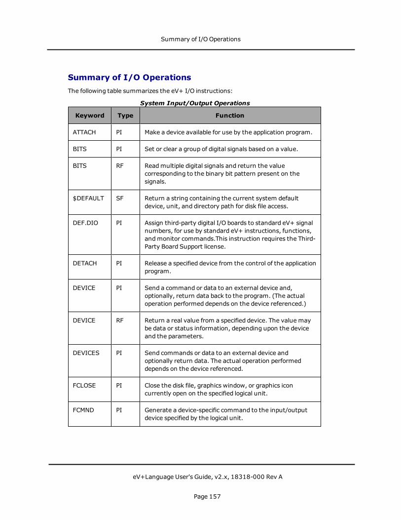
Summary of I/O OperationsThe following table summarizes the eV+ I/O instructions:
Keyword Type Function
ATTACH PI Make a device available for use by the application program.
BITS PI Set or clear a group of digital signals based on a value.
BITS RF Readmultiple digital signals and return the valuecorresponding to the binary bit pattern present on thesignals.
$DEFAULT SF Return a string containing the current system defaultdevice, unit, and directory path for disk file access.
DEF.DIO PI Assign third-party digital I/O boards to standard eV+ signalnumbers, for use by standard eV+ instructions, functions,andmonitor commands.This instruction requires the Third-Party Board Support license.
DETACH PI Release a specified device from the control of the applicationprogram.
DEVICE PI Send a command or data to an external device and,optionally, return data back to the program. (The actualoperation performed depends on the device referenced.)
DEVICE RF Return a real value from a specified device. The value maybe data or status information, depending upon the deviceand the parameters.
DEVICES PI Send commands or data to an external device andoptionally return data. The actual operation performeddepends on the device referenced.
FCLOSE PI Close the disk file, graphics window, or graphics iconcurrently open on the specified logical unit.
FCMND PI Generate a device-specific command to the input/outputdevice specified by the logical unit.
System Input/Output Operations
Summary of I/O Operations
eV+Language User's Guide, v2.x, 18318-000 Rev A
Page 157

Keyword Type Function
FEMPTY PI Empty any internal buffers in use for a disk file or a graphicswindow by writing the buffers to the file or window ifnecessary.
FOPENR PI Open a disk file for read-only.
FOPENW PI Open a disk file for read-write.
FOPENA PI Open a disk file for read-write-append.
FOPEND PI Open a disk directory for read.
FSEEK PI Position a file open for random access and initiate a readoperation on the specified record.
GETC RF Return the next character (byte) from a device or inputrecord on the specified logical unit.
IOSTAT RF Return status information for the last input/outputoperation for a device associated with a logical unit.
PROMPT PI Display a string on the system terminal andwait foroperator input.
READ PI Read a record from an open file or from an attached devicethat is not file oriented.
RESET PI Turn off all the external output signals.
SETDEVICE PI Initialize a device or set device parameters. (The actualoperation performed depends on the device referenced.)
SIG RF Return the logical AND of the states of the indicated digitalsignals.
SIG.INS RF Return an indication of whether or not a digital I/O signal isconfigured for use by the system, or whether or not asoftware signal is available in the system.
SIGNAL PI Turn on or off external digital output signals or internalsoftware signals.
Summary of I/O Operations
eV+Language User's Guide, v2.x, 18318-000 Rev A
Page 158

Keyword Type Function
TYPE PI Display the information described by the outputspecifications on the system terminal. A blank line is outputif no argument is provided.
WRITE PI Write a record to an open file or to an attached device thatis not file oriented.
PI: Program Instruction, RF: Real-Valued Function, P: Parameter, SF: StringFunction
Summary of I/O Operations
eV+Language User's Guide, v2.x, 18318-000 Rev A
Page 159


Graphics Programming
NOTE: This feature is not supported in eV+ version v2.x.
The ACE software provides a graphical interface for programming your motion (and vision)system. Further, the User Interface Designer, which is includedwith the ACE software,provides a complete tool set for building custom interfaces for your applications. Therefore,Omron Adept strongly recommends that you use the ACE software for this functionality. Formore details, see the chapter User Interface Designer in the ACE User's Guide.
Graphics Programming
eV+Language User's Guide, v2.x, 18318-000 Rev A
Page 161
Creating WindowseV+ communicates to windows through logical units, with logical unit numbers (LUNs) 20 to23 reserved for window use. (Each task has access to its own set of four LUNs.) The basicstrategy for using a window (or any of the graphics instructions) is:
1. ATTACH to a logical unit
2. FOPEN a window on the logical unit
3. Perform the window's tasks (or graphics operations)
4. FCLOSE the window
5. FDELETE the window
6. DETACH from the logical unit
ATTACH Instruction
The ATTACH instruction sets up a communications path so a window can be written to andread from. The syntax for the ATTACH instruction is:
ATTACH (glun, 4) "GRAPHICS"
glun variable that receives the number of the attached graphics logical unit.(All menus and graphics commands that take place within a window willalso use glun.)
FOPEN Instruction
FOPEN creates a new window or reselects an existing window for input and output. When awindow is created, its name is placed in the list of available windows displayedwhen theadept logo is clicked on. The simplified syntax for FOPEN is:
FOPEN (glun) "window_name /MAXSIZE width height"
glun The logical unit already ATTACHed to.
window_name
The title that appears at the top of the window. Also used to close andselect the window.
width/height Specify the largest size the window can be opened to.
This instruction will give you a window with all the default attributes. See the description ofFOPEN and FSET in the eV+ Language Reference Guide for details on how to control theattributes of a window e6 for example, background color, size, and scrolling.
CreatingWindows
eV+Language User's Guide, v2.x, 18318-000 Rev A
Page 162

FCLOSE Instruction
FCLOSE closes a window to input and output (but does not erase it or remove it frommemory). The syntax for FCLOSE is:
FCLOSE (glun)
glun The logical unit number specified in the FOPEN instruction that openedthe window.
FDELETE Instruction
FDELETE removes a closed, attachedwindow from the screen and from graphics memory.The syntax for FDELETE is
FDELETE (glun) "window_name"
glun The same values as specified in the FOPEN instruction that created thewindow.
DETACH Instruction
DETACH frees up a LUN for use by a subsequent ATTACH instruction. The syntax for DETACHis:
DETACH (glun)
glun The LUN specified in a previous ATTACH instruction.
Custom Window Example
This section of code will create and delete a window:
AUTO glun ; Graphics window LUN
ATTACH (glun, 4) "GRAPHICS" ; Attach to a window LUN
; Open the window "Test" with a maximum size of; 400 x 300 pixels
FOPEN(glun) "Test","/MAXSIZE 400 300"
; Your code for processing within the window; goes here; e.g:
GTYPE (glun) 10, 10, "Hello!"
; When the window is no longer needed, close and delete the; window and detach from the logical unit
FCLOSE (glun)
CreatingWindows
eV+Language User's Guide, v2.x, 18318-000 Rev A
Page 163

FDELETE (glun) "Test"DETACH (glun)
CreatingWindows
eV+Language User's Guide, v2.x, 18318-000 Rev A
Page 164
Monitoring EventsThe key to pointing-device-driven programming is an event loop. In an event loop, you waitfor an event (from the keyboard or pointer device) andwhen the correct event occurs in theproper place, your program initiates some appropriate action. eV+ can monitor manydifferent events including button up, button down, double click, open window, andmenuselect. The example code in the following sections will use event 2, button up, and event 14,menu select. For details on the different events that can be monitored, see thedocumentation for the GETEVENT program instruction in the eV+ Language ReferenceGuide.
The basic strategy for an event loop is:
1. Wait for an event to occur.
2. When an event is detected:
a. If it is the desired event, go to step 3
b. Otherwise, return to step 1.
3. Check the data from the event array (not necessary for event 14, menu select):
a. If it is appropriate, go to step 4.
b. Otherwise, return to step 1.
4. Initiate appropriate action.
5. Return to step 1.
GETEVENT Instruction
The instruction that initiates monitoring of pointer device and keyboard events is GETEVENT.Its simplified syntax is:
GETEVENT (lun) event[]
lun Logical unit number of the window to be monitored.
event[] Array into which the results of the detected event are stored. Thevalue stored in event[0] indicates which event was detected.
If event[0] is 2, a button-up event was detected, in which case:
event[1] indicates the number of the button pressed. (For two-buttondevices, 2 = left button, 4 = right button. For three-buttondevices, 1 = left button, 2 = middle button, 4 = right button.)
event[2] is the X value of the pointer location of the click.
event[3] is the Y value of the pointer location of the click.
Monitoring Events
eV+Language User's Guide, v2.x, 18318-000 Rev A
Page 165
If event[0] is 14, a click on amenu bar selection was detected, in which case:
If event[1] is 0, a click has been made to the top-level menu bar. In this case,an FSET instruction must be executed to display the pull-downoptions under the menu bar selection and event[2] is the number(from left to right) of the menu bar option selected.
If event[1] is 1, then a selection from a pull-down menu has been made andevent[2] is the number of the pull-down option selected.
You cannot use the GETEVENT instruction to specify which events to monitor. It monitors allthe events that are enabled for the window. For details on using the /EVENT argument forenabling and disabling the monitoring of various events, see the documentation for theFOPEN and FSET program instructions in the eV+ Language Reference Guide.
FSET Instruction
FSET is used to alter the characteristics of a window openedwith an FOPEN instruction, andto display pull-down menus. We are going to describe only the use of FSET to create the top-level menu bar, create the pull-down menu selections below the top-level menu, and initiatemonitoring of events. The instruction for displaying a top-level menu is:
FSET (glun) " /MENU 'item1' 'item2' ... 'item10' "
glun is the logical unit of the window the menu is displayed in.
item1-item10 are the menu titles for a top-level bar menu. The items appearfrom left to right.
The instruction to display a pull-down menu (called when event[0] = 14 and event[1] = 0) is:
FSET (glun) "/PULLDOWN", top_level#," 'item1' ... ' itemn '"
top_level# is the number of the top-level selection the pull-down menu is to appearunder.
item1-itemn
are the menu items in the pull-down menu. The items appear from topto bottom.
The relationship between these two uses of FSET will become clear when we actually build amenu structure.
The basic FSET instruction for monitoringmenu andmouse events is:
FSET (glun) "/EVENT BUTTON MENU"
Monitoring Events
eV+Language User's Guide, v2.x, 18318-000 Rev A
Page 166
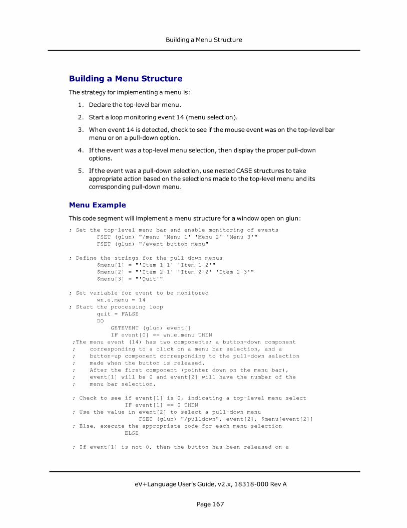
Building a Menu StructureThe strategy for implementing amenu is:
1. Declare the top-level bar menu.
2. Start a loopmonitoring event 14 (menu selection).
3. When event 14 is detected, check to see if the mouse event was on the top-level barmenu or on a pull-down option.
4. If the event was a top-level menu selection, then display the proper pull-downoptions.
5. If the event was a pull-down selection, use nested CASE structures to takeappropriate action based on the selections made to the top-level menu and itscorresponding pull-down menu.
Menu Example
This code segment will implement a menu structure for a window open on glun:
; Set the top-level menu bar and enable monitoring of eventsFSET (glun) "/menu 'Menu 1' 'Menu 2' 'Menu 3'"FSET (glun) "/event button menu"
; Define the strings for the pull-down menus$menu[1] = "'Item 1-1' 'Item 1-2'"$menu[2] = "'Item 2-1' 'Item 2-2' 'Item 2-3'"$menu[3] = "'Quit'"
; Set variable for event to be monitoredwn.e.menu = 14
; Start the processing loopquit = FALSEDO
GETEVENT (glun) event[]IF event[0] == wn.e.menu THEN
;The menu event (14) has two components; a button-down component; corresponding to a click on a menu bar selection, and a; button-up component corresponding to the pull-down selection; made when the button is released.; After the first component (pointer down on the menu bar),; event[1] will be 0 and event[2] will have the number of the; menu bar selection.
; Check to see if event[1] is 0, indicating a top-level menu selectIF event[1] == 0 THEN
; Use the value in event[2] to select a pull-down menuFSET (glun) "/pulldown", event[2], $menu[event[2]]
; Else, execute the appropriate code for each menu selectionELSE
; If event[1] is not 0, then the button has been released on a
Building a Menu Structure
eV+Language User's Guide, v2.x, 18318-000 Rev A
Page 167

; pull-down selection and:; event[1] will have the value of the top-level selection (menu); event[2] will have the value of the pull-down selection (item)
menu = event[1]item = event[2]
; The outer CASE structure checks the top-level menu selection; The inner CASE structure checks the item selected from the pull-down
CASE menu OFVALUE 1: ;Menu 1
CASE item OFVALUE 1:
;code for Item 1-1VALUE 2:
;code for Item 1-2END
VALUE 2: ;Menu 2CASE item OF
VALUE 1:;code for Item 2-1
VALUE 2:;code for Item 2-2
VALUE 3:;code for Item 2-3
ENDVALUE 3: ;Menu 3
CASE item OFVALUE 1:
quit = TRUE ;time to quitEND
END ; case menu ofEND ; if event[1]
END ; if event[0]UNTIL quit
.END
Implementing the above code and then clicking on Menu 2 would result in the window shownin the following figure.
Building a Menu Structure
eV+Language User's Guide, v2.x, 18318-000 Rev A
Page 168

Sample Menu
Defining Keyboard Shortcuts
If you are using AdeptWindows, you can create keyboard shortcuts on menu and pull-downitems by placing an ampersand (&) before the desired letter. For example:
FSET(lun) "/menu '&File' '&Edit'"
In this example, the letters F and E are used as shortcuts when pressedwith the ALT key.Thus, pressing ALT+F displays the File menu and ALT+E displays the Edit menu. The lettersF and E are underlined on the menu or pull-down item to indicate the keyboard shortcut.
Building a Menu Structure
eV+Language User's Guide, v2.x, 18318-000 Rev A
Page 169

Creating ButtonsCreating a button in a window is a simple matter of placing a graphic representing yourbutton on the screen, and then looking to see if a mouse event occurred within the confinesof that graphic.
GPANEL Instruction
The GPANEL instruction is useful for creating standard button graphics. The syntax forGPANEL is:
GPANEL (glun, mode) x, y, dx, dy
glun The logical unit of the window the button is in.
mode is replacedwith:
0 indicating a raised, ungrooved panel
2 indicating a sunken, ungrooved panel
4 indicating a raised, grooved panel
6 indicating a sunken, grooved panel
(Adding 1 to any of the mode values fills the panel with foregroundcolor.)
x y Coordinates of the upper left corner of the button.
dx dy Width and height of the button.
Button Example
This code segment places a button on the screen and then monitor a button-up event at thatbutton (the logical unit the button is accessingmust be ATTACHed and FOPENed):
; Initialize monitoring of button events for a buttonFSET (glun) "/event button"
; Draw a 45x45 pixel panel at window coordinates 100,100GPANEL (glun, 0) 100, 100, 45, 45
; Put a label in the buttonGTYPE (glun) 102, 122, "Label"
; Declare a variable for pointer event 2 (button up)btn.up = 2
; Set a variable that will stop the monitoring of button; events
hit = FALSE; Start a loop waiting for a button-up event
DOGETEVENT (glun) event[]
Creating Buttons
eV+Language User's Guide, v2.x, 18318-000 Rev A
Page 170

; The status of a button event will be stored in event[0].; Look to see ifthat event was a button-up event.
IF event[0] == btn.up THEN; Check if the button-up event was within the button area; The x location is in event[1], the y location in event[2]
hit = (event[2] > 99) AND (event[2] < 146)hit = hit AND (event[3] > 99) AND (event[3] < 146)
ENDUNTIL hit
; The code for reacting to a button press is placed here.
This code will work for a single button but will become very unwieldy if several buttons areused. In the case of several buttons, you should place the button locations in arrays (or atwo-dimensional array) and then pass these locations to a subroutine that checks whetherthe mouse event was within the array parameters passed to it.
Creating Buttons
eV+Language User's Guide, v2.x, 18318-000 Rev A
Page 171
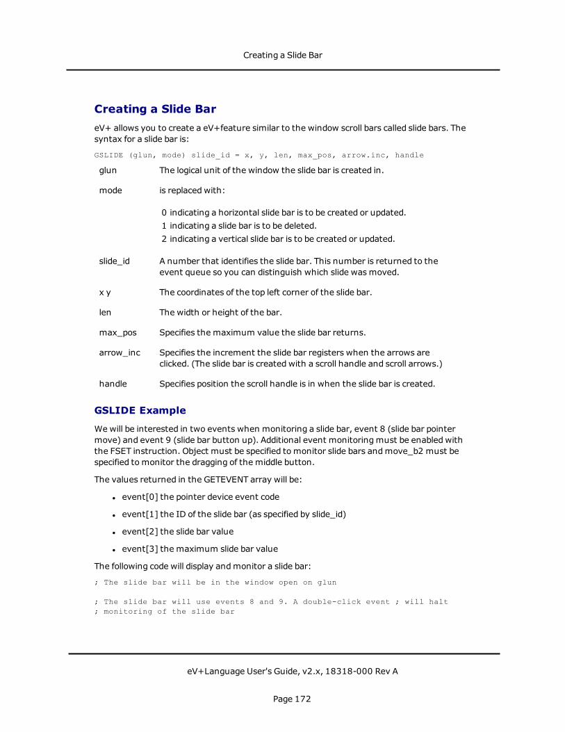
Creating a Slide BareV+ allows you to create a eV+feature similar to the window scroll bars called slide bars. Thesyntax for a slide bar is:
GSLIDE (glun, mode) slide_id = x, y, len, max_pos, arrow.inc, handle
glun The logical unit of the window the slide bar is created in.
mode is replacedwith:
0 indicating a horizontal slide bar is to be created or updated.1 indicating a slide bar is to be deleted.2 indicating a vertical slide bar is to be created or updated.
slide_id A number that identifies the slide bar. This number is returned to theevent queue so you can distinguish which slide wasmoved.
x y The coordinates of the top left corner of the slide bar.
len The width or height of the bar.
max_pos Specifies the maximum value the slide bar returns.
arrow_inc Specifies the increment the slide bar registers when the arrows areclicked. (The slide bar is created with a scroll handle and scroll arrows.)
handle Specifies position the scroll handle is in when the slide bar is created.
GSLIDE Example
Wewill be interested in two events when monitoring a slide bar, event 8 (slide bar pointermove) and event 9 (slide bar button up). Additional event monitoringmust be enabled withthe FSET instruction. Object must be specified to monitor slide bars andmove_b2 must bespecified to monitor the dragging of the middle button.
The values returned in the GETEVENT array will be:
l event[0] the pointer device event code
l event[1] the ID of the slide bar (as specified by slide_id)
l event[2] the slide bar value
l event[3] the maximum slide bar value
The following code will display andmonitor a slide bar:
; The slide bar will be in the window open on glun
; The slide bar will use events 8 and 9. A double-click event ; will halt; monitoring of the slide bar
Creating a Slide Bar
eV+Language User's Guide, v2.x, 18318-000 Rev A
Page 172
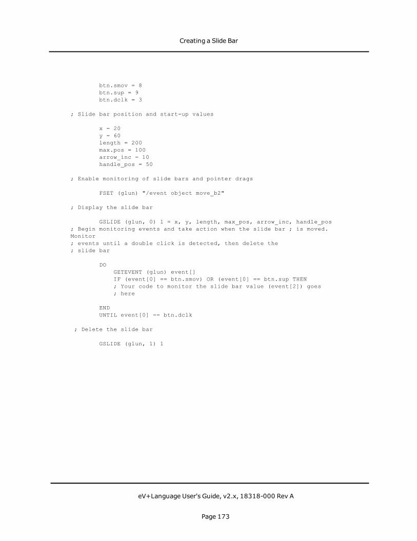
btn.smov = 8btn.sup = 9btn.dclk = 3
; Slide bar position and start-up values
x = 20y = 60length = 200max.pos = 100arrow_inc = 10handle_pos = 50
; Enable monitoring of slide bars and pointer drags
FSET (glun) "/event object move_b2"
; Display the slide bar
GSLIDE (glun, 0) 1 = x, y, length, max_pos, arrow_inc, handle_pos; Begin monitoring events and take action when the slide bar ; is moved.Monitor; events until a double click is detected, then delete the; slide bar
DOGETEVENT (glun) event[]IF (event[0] == btn.smov) OR (event[0] == btn.sup THEN; Your code to monitor the slide bar value (event[2]) goes; here
ENDUNTIL event[0] == btn.dclk
; Delete the slide bar
GSLIDE (glun, 1) 1
Creating a Slide Bar
eV+Language User's Guide, v2.x, 18318-000 Rev A
Page 173

Graphics Programming ConsiderationsButtons andmenus can be monitored in the same window. However, the code will getcomplicated, and you might consider using different windows when the button andmenustructure becomes complex.
Only one pull-down menu can be active at any time.
Design your windows with the followingmechanical and aesthetic considerations:
l Keep your windows as simple and uncluttered as possible. Use color carefully andpurposefully.
l If you are usingmultiple windows, use similar graphic elements so the screenelements become familiar and intuitive.
l Let the operator know what is going on. Never leave the operator in the dark as to thestatus of a button push or menu selection.
l Whenever possible, have your windowsmimic the real work world of the operator.
In the interest of clarity, the examples in this chapter have not been generalized. When youactually program an application, use generalized subroutine calls for commonly used code, oryour code will quickly become unmanageable.
Using IOSTAT( )
The example code in this chapter leaves out critical error detection and recovery procedures.Effective application code requires these procedures. The IOSTAT function should be used tobuild error-handling routines for use with every ATTACH, FOPEN, FCLOSE, and FSETinstruction. The syntax for using IOSTAT to check the status of I/O requests is:
IOSTAT(lun)
lun The LUN specified in the previous I/O request.
The IOSTAT function returns the following values:
1 if the last operation was successful
0 if the last operation is not yet complete
< 0 if the last operation failed, a negative number corresponding to a standardOmron Adept error code will be returned.
The following code checks for I/O errors:
; Issue I/O instruction (ATTACH, FOPEN, etc.)IF IOSTAT(lun) < 0 THEN
;your code to handle the errorEND
; The ERROR function can be used to return the text
Graphics Programming Considerations
eV+Language User's Guide, v2.x, 18318-000 Rev A
Page 174

; of an error number. The code line is:TYPE $ERROR(IOSTAT(lun))
Managing Windows
Windows can be:
l Hidden (but not deleted)
A hidden window is removed from the screen but not from graphics memory, and itcan be retrieved at any time:
FSET(glun) "/NODISPLAY" ;Hide a windowFSET(glun) "/DISPLAY" ;Redisplay a window
l Sent behind the parent's window stack:
FSET(glun) "/STACK -1"
l Brought to the front of the window stack:
FSET(glun) "STACK 1"
If you will not be reading events from a window, open it in write-only mode to save memoryand processing time.
Only the task that opened a window in read/write mode can read from it (monitor events).
Multiple tasks can write to an open window. A second task can write to an already openwindow by executing its own ATTACHandOPEN for the window. The logical units' numbersneed not match, but the window namemust be the same. If a task has the window Testopen, other tasks can write to the window by:
ATTACH(lun_1, 4) "GRAPHICS"FOPEN(lun_1) "Test /MAXSIZE 200 200 /WRITEONLY"
Graphics Programming Considerations
eV+Language User's Guide, v2.x, 18318-000 Rev A
Page 175

Communicating With the System WindowsThe system has three operating system level windows: the main window, the monitorwindow, and the vision window (on systems with the AdeptVision option).
The Main Window
You can place menu options on the top-level menu bar by opening the window \Screen_1.For example:
ATTACH (glun, 2) "GRAPHICS"FOPEN(glun)"\Screen_1"FSET (glun)"/event menu"FSET (glun)"/menu 'item1' 'item2' 'item3'"
opens the main window and place three items on the top-level menu bar. Pull-downs andevent monitoring can proceed as described earlier. The instruction:
FSET (glun) "/menu "
deletes the menu items.
The Monitor Window
The monitor window can be opened in write-only mode to change the characteristics of themonitor window. For example, the following instruction opens the monitor window, disablesscrolling, and disallowsmoving of the window:
FOPEN (glun) "Monitor /WRITEONLY /SPECIAL NOPOSITION NOSIZE"
To prevent a user from accessing the monitor window, use the instruction:
FOPEN (glun) "Monitor /WRITEONLY /NOSELECTABLE"
To allow access:
FSET (glun) "/SELECTABLE"
The Vision Window
For systems equippedwith the Adept Vision option, text or graphics can be output to thevision window, and events can be monitored in the vision window. To communicate with thevision window, you open it just as you would any other window. For the window name youmust use Vision. For example:
FOPEN (glun) "Vision"
Remember, graphics output to the vision window is displayed only when a graphics displaymode or overlay is selected. When you are finished communicating with the vision window,close and detach from it just as you would any other window. This will free up the logical unit,
CommunicatingWith the System Windows
eV+Language User's Guide, v2.x, 18318-000 Rev A
Page 176

but will not delete the vision window. You can close and detach from the vision window, butyou cannot delete it.
To preserve the vision system pull-down menus, open the window in write-only mode:
FOPEN (glun) "Vision /WRITEONLY"
The following example opens the vision window, writes to the vision window, and detachesthe vision window:
.PROGRAM label.blob()
; ABSTRACT: This program demonstrates how to attach to the; vision window and how to use the millimeter scaling mode of; the GTRANS instruction to label a "blob" in the vision; window.;
AUTO vluncam = 1; Attach the vision window and get a logical unit numberATTACH (vlun, 4) "GRAPHICS"IF IOSTAT(vlun) < 0 GOTO 100FOPEN (vlun) "Vision" ;Open the vision windowIF IOSTAT(vlun) < 0 GOTO 100; Select display mode and graphics modeVDISPLAY (cam) 1, 1 ;Display grayscale frame and graphics; Take a picture and locate an objectVPICTURE (cam) ;Take a processed pictureVLOCATE (cam, 2) "?" ;Attempt to locate an objectIF VFEATURE(1) THEN ;If an object was found...
GCOLOR (vlun) 1 ;Select the color blackGTRANS (vlun, 2) ;Select millimeter scalingGTYPE (vlun) DX(vis.loc), DY(vis.loc), "Blob", 3
ELSE ;Else if object was NOT found...GCOLOR (vlun) 3 ;Select the color redGTRANS (vlun, 0) ;Select pixel scalingGTYPE (vlun) 100, 100, "No object found!", 3
END; Detach (frees up the communications path)DETACH (vlun)
100 IF (IOSTAT(vlun) < 0) THEN ; Check for errorsTYPE $ERROR(IOSTAT(vlun))
END
.END
CommunicatingWith the System Windows
eV+Language User's Guide, v2.x, 18318-000 Rev A
Page 177

Additional Graphics InstructionsThe following table lists the graphics instructions available in the eV+ programming language.For complete details on any instruction, click on the command name in the table, or refer tothe keyword documentation available in the eV+ Language Reference Guide.
Command Action
GARC Draw an arc or circle in a graphics window.
GCHAIN Draw a chain of points.
GCLEAR Clear an entire window to the background color.
GCLIP Constrain the area of a window within which graphics are displayed.
GCOLOR Set the foreground and background colors for subsequent graphicsinstructions.
GCOPY Copy one area of a graphics window to another area in the window.
GFLOOD Flood an area with foreground color.
GICON Allows you to display icons on the screen. You can access thepredefined Omron Adept icons or use your own icons.
GLINE Draw a line.
GLINES Draw multiple lines.
GLOGICAL Set the drawingmode for the next graphics instruction. (Useful forerasing existing graphics and simulating the dragging of a graphicacross the screen.)
GPOINT Draw a single point.
GRECTANGLE Draw a rectangle.
GSCAN Draw a series of horizontal lines.
GSLIDE Create a slide bar.
GTEXTURE Develop a texture for subsequent graphics. Set subsequent graphics
List of Graphics Instructions
Additional Graphics Instructions
eV+Language User's Guide, v2.x, 18318-000 Rev A
Page 178
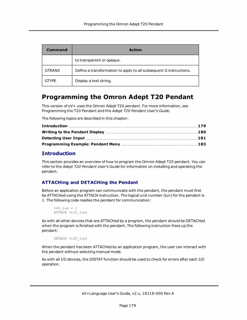
Command Action
to transparent or opaque.
GTRANS Define a transformation to apply to all subsequent G instructions.
GTYPE Display a text string.
Programming the Omron Adept T20 PendantThis version of eV+ uses the Omron Adept T20 pendant. For more information, seeProgramming the T20 Pendant and the Adept T20 Pendant User's Guide.
The following topics are described in this chapter:
Introduction 179Writing to the Pendant Display 180Detecting User Input 181Programming Example: Pendant Menu 183
IntroductionThis section provides an overview of how to program the Omron Adept T20 pendant. You canrefer to the Adept T20 Pendant User’s Guide for information on installing and operating thependant.
ATTACHing and DETACHing the Pendant
Before an application program can communicate with the pendant, the pendant must firstbe ATTACHed using the ATTACH instruction. The logical unit number (lun) for the pendant is1. The following code readies the pendant for communication:
t20_lun = 1ATTACH (t20_lun)
As with all other devices that are ATTACHed by a program, the pendant should be DETACHedwhen the program is finishedwith the pendant. The following instruction frees up thependant:
DETACH (t20_lun)
When the pendant has been ATTACHed by an application program, the user can interact withthe pendant without selectingmanual mode.
As with all I/O devices, the IOSTAT function should be used to check for errors after each I/Ooperation.
Programming the Omron Adept T20 Pendant
eV+Language User's Guide, v2.x, 18318-000 Rev A
Page 179
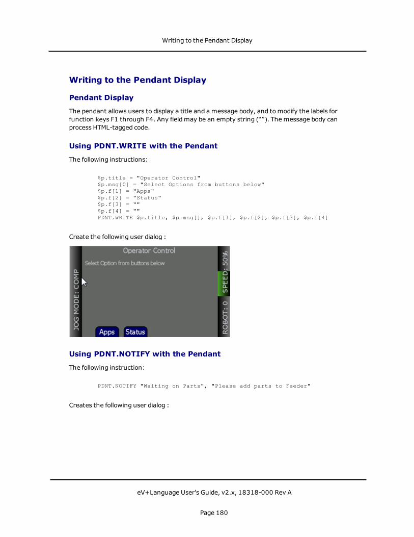
Writing to the Pendant Display
Pendant Display
The pendant allows users to display a title and amessage body, and tomodify the labels forfunction keys F1 through F4. Any fieldmay be an empty string (“”). The message body canprocess HTML-tagged code.
Using PDNT.WRITE with the Pendant
The following instructions:
$p.title = "Operator Control"$p.msg[0] = "Select Options from buttons below"$p.f[1] = "Apps"$p.f[2] = "Status"$p.f[3] = ""$p.f[4] = ""PDNT.WRITE $p.title, $p.msg[], $p.f[1], $p.f[2], $p.f[3], $p.f[4]
Create the following user dialog :
Using PDNT.NOTIFY with the Pendant
The following instruction:
PDNT.NOTIFY "Waiting on Parts", "Please add parts to Feeder"
Creates the following user dialog :
Writing to the Pendant Display
eV+Language User's Guide, v2.x, 18318-000 Rev A
Page 180
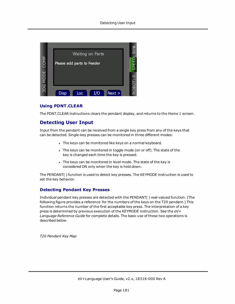
Using PDNT.CLEAR
The PDNT.CLEAR instructions clears the pendant display, and returns to the Home 1 screen.
Detecting User InputInput from the pendant can be received from a single key press from any of the keys thatcan be detected. Single-key presses can be monitored in three different modes:
l The keys can be monitored like keys on a normal keyboard.
l The keys can be monitored in toggle mode (on or off). The state of thekey is changed each time the key is pressed.
l The keys can be monitored in level mode. The state of the key isconsidered ON only when the key is held down.
The PENDANT( ) function is used to detect key presses. The KEYMODE instruction is used toset the key behavior.
Detecting Pendant Key Presses
Individual pendant key presses are detected with the PENDANT( ) real-valued function. (Thefollowing figure provides a reference for the numbers of the keys on the T20 pendant.) Thisfunction returns the number of the first acceptable key press. The interpretation of a keypress is determined by previous execution of the KEYMODE instruction. See the eV+Language Reference Guide for complete details. The basic use of these two operations isdescribed below.
T20 Pendant Key Map
Detecting User Input
eV+Language User's Guide, v2.x, 18318-000 Rev A
Page 181

Keyboard Mode
The default mode is Keyboard. If a PENDANT( ) function requests any keyboard input, the keynumber of the first Keyboardmode key pressed is returned. The following code detects thefirst function key pressed:
; Set the function keys to keyboard modeKEYMODE 1,4 = 0
; Wait for a key press from keys 1 - 4DO
key = PENDANT(0)UNTIL key < 5
The arguments to the KEYMODE instruction indicate that pendant keys 1 through 4 are to beconfigured in Keyboardmode. The 0 argument to the PENDANT( ) function indicates that thekey number of the first key pressed is to be returned.
Toggle Mode
To detect the state of a key in Toggle mode, the PENDANT( ) function must specify the key tobe monitored.
When a key is configured as a toggle key, its state is maintained as ON (-1) or OFF (0). Thestate is toggled each time the key is pressed. The following code sets the F1 key to Togglemode andwaits until F1 is pressed:
; Set the F1 key to toggleKEYMODE 1 = 1
; Wait until the F1 key is pressedWHILE NOT PENDANT(1) DO
RELEASE -1END
Level Mode
To detect the state of a key in Level mode, the PENDANT( ) function must specify the key tobe monitored.
When a key has been configured as a level key, the state of the key is ON as long as the key ispressed. When the key is not pressed, its state is OFF. The following code will poll the OKbutton's state until it has been held down for an amount of time. If it is released prematurely,the counter is reset.
ATTACH(1) "PENDANT"counter = 0KEYMODE 18, 18 = 2
WHILE counter < 20 DOIF PENDANT(18) THEN
counter = counter+1ELSE
counter = 0END
Detecting User Input
eV+Language User's Guide, v2.x, 18318-000 Rev A
Page 182
WAIT.EVENT , 0.1ENDDETACH (1)
Notes on Key Behaviors
On the T20 pendant, all Green keys and Select Robot will still have their normal functionalitywhen in a Custom Window (through PDNT.WRITE). All other keys will have their primaryfunctionality disabled. These keys are intended to be read by the eV+ program through thePENDANT instruction.
Monitoring the Pendant Speed Signal
The speed that is sent from the pendant has a value from 1 to 100 depending on thecurrently displayed speed on the Pendant. An argument of -2 to the PENDANT( ) functionreturns this value to eV+. The following example shows how to print the currently displayedPendant speed to the monitor.
; Set the OK key to toggleKEYMODE 18 = 1
; Display speed value until the OK key is pressedDO
TYPE PENDANT(-2)WAIT
UNTIL PENDANT(18)
Reading the State of the Pendant
It is good programming practice to check the state of the pendant before ATTACHing to it.The instruction:
cur.state = PENDANT(-3)
returns a value to be interpreted as follows:
1. Indicates that the pendant is in the Background state (not ATTACHed to anapplication program).
2. Indicates that an error is being displayed.
3. Indicates that the pendant is in the USER state (ATTACHed to an applicationprogram).
See the section Programming Example: Pendant Menu for a program example that checksthe pendant state.
Programming Example: Pendant MenuThe following code implements a menu structure on the Omron Adept T20 pendant. Theresulting screens are shown after the code sample.
Programming Example: Pendant Menu
eV+Language User's Guide, v2.x, 18318-000 Rev A
Page 183
.PROGRAM operatorcontrol(); ABSTRACT: This program creates and monitors a menu structure on the T20.;; INPUT PARAMS: None;; OUTPUT PARAMS: None;; GLOBAL VARS: None
AUTO $p.title, $p.msg[15], $p.f[15], key, app.selAUTO pendant.lun
pendant.lun = 1
; Attach to the Pendant
ATTACH (pendant.lun)
; Verify ATTACH was successful
IF IOSTAT(pendant.lun) <> 1 THENTYPE "Pendant is either busy or not connected"GOTO 100 ;ERROR
END
; Menu elements
$prog.list[0] = "Cookie1"$prog.list[1] = "Cookie2"$prog.list[2] = "Cookie3"$prog.list[3] = "Cookie4"$prog.list[4] = "Cookie5"prog.len = 5
; Initialize variables
key = -1app.sel = 0$p.title = ""FOR i = 0 TO 10
$p.msg[i] = ""ENDFOR i = 0 TO 4
$p.f[i] = ""END
; Screen 1 - Operator Control
$p.title = "Operator Control"$p.msg[0] = "Select Option from buttons below"$p.f[1] = "Apps"$p.f[2] = "Status"$p.f[3] = ""$p.f[4] = ""
Programming Example: Pendant Menu
eV+Language User's Guide, v2.x, 18318-000 Rev A
Page 184

; Display Custom Message
PDNT.WRITE $p.title, $p.msg[], $p.f[1], $p.f[2], $p.f[3], $p.f[4]
WHILE TRUE DOKEYMODE 1, 4 = 0 ;Set Keymode of F keys detect next keypresskey = PENDANT(0) ;Obtain Pressed keyCASE key OF
VALUE 1: ;Apps pressed, continue to Screen 2GOTO 10
VALUE 2: ;Display Filler Notification; This will be cleared on Pendant by pressing OK or CancelPDNT.NOTIFY "Status", "No Program Running" ;Obtain info of
task 1 hereEND
END
; Setup Screen 2
10 $p.title = "List of Applications"$p.f[1] = "Run"$p.f[2] = "Up"$p.f[3] = "Down"$p.f[4] = "Done"FOR i = 0 TO 10
$p.msg[i] = ""ENDFOR i = 0 TO prog.len-1
IF i == app.sel THEN; Underline the currently selected Application$p.msg[i] = $p.msg[i]+"<center><u>"+$prog.list[i]+"
</u></center>"ELSE
$p.msg[i] = $p.msg[i]+"<center>"+$prog.list[i]+"</center>"END
END
; Display Screen 2 - List of Applications
PDNT.WRITE (prog.len) $p.title, $p.msg[], $p.f[1], $p.f[2], $p.f[3],$p.f[4]
KEYMODE 1, 28 = 0WHILE TRUE DO
key = PENDANT(0)CASE key OF
VALUE 1, 18: ;F1 or OKCALLS $prog.list[app.sel]()GOTO 10 ;
VALUE 2, 17: ;F2 or Up arrowapp.sel = (app.sel-1) MOD prog.lenGOTO 10
VALUE 3, 21: ;F3 or Down arrowapp.sel = (app.sel+1) MOD prog.len
Programming Example: Pendant Menu
eV+Language User's Guide, v2.x, 18318-000 Rev A
Page 185

GOTO 10VALUE 4: ;F4
GOTO 90END
END
; Finished normally, clear screen and detach
90 PDNT.CLEARDETACH (1)
100 RETURN
.END
Screen 1
Screen 2
Programming Example: Pendant Menu
eV+Language User's Guide, v2.x, 18318-000 Rev A
Page 186

Conveyor TrackingThis chapter describes the Conveyor Tracking (moving-line) feature.
The ACE software provides a graphical interface for programming your Omron Adept motion(and vision) system. Further, the ACE Process Manager, which is includedwith the ACEsoftware, allows you to build conveyor-tracking applications through a point-and-clickinterface. Therefore, Omron Adept strongly recommends that you use the ACE software forthis functionality. For more details, see the chapter Process Control in the ACE User's Guide.Optionally, you can use eV+ tomanually program a conveyor-tracking application, asdescribed in this chapter.
The following sections contain installation and application instructions for using theconveyor-tracking feature in eV+. Before using this chapter, you should be familiar with eV+and the basic operation of the robot.
Introduction to Conveyor Tracking 189Installation 190Calibration 191Basic Programming Concepts 192Conveyor-Tracking Programming 199Sample Programs 201
Conveyor Tracking
eV+Language User's Guide, v2.x, 18318-000 Rev A
Page 187

Conveyor Tracking
eV+Language User's Guide, v2.x, 18318-000 Rev A
Page 188
Introduction to Conveyor Tracking
NOTE: The ACE software provides the following functionality through its graphical userinterface. Therefore, Omron Adept strongly recommends that you use the ACE software.
This chapter describes the Conveyor Tracking (moving-line) feature. The moving-line featureallows the programs to specify locations that are automatically modified to compensate forthe instantaneous position of a conveyor belt. Motion locations that are defined relative to abelt can be taught and played back while the belt is stationary or moving at arbitrarilyvarying speeds. Conveyor tracking is available only for systems that have the optional eV+Extensions software.
For eV+ to determine the instantaneous position and speed of a belt, the belt must beequippedwith a device to measure its position and speed. As part of the moving-linehardware option, Omron Adept provides an interface for coordinating two separate conveyorbelts. Robot motions and locations can be specified relative to either belt.
There are no restrictions concerning the placement or orientation of a conveyor belt relativeto the robot. In fact, belts that move uphill or downhill (or at an angle to the reference frameof the robot) can be treated as easily as those that move parallel to an axis of the robotreference frame. The only restriction regarding a belt is that its motion must follow astraight-line path in the region where the robot is to work.
The following sections contain installation and application instructions for using the moving-line feature. Before using this chapter, you should be familiar with eV+ and the basicoperation of the robot.
Introduction to Conveyor Tracking
eV+Language User's Guide, v2.x, 18318-000 Rev A
Page 189
InstallationTo set up a conveyor belt for use with a robot controlled by the eV+ system:
1. Install all the hardware components and securely fasten them in place. The conveyorframe and robot base must be mounted rigidly so that nomotion can occur betweenthem.
2. Install the encoder on the conveyor.
3. Since any jitter of the encoder will be reflected as jitter in motions of the robot whiletracking the belt, make sure the mechanical connection between the belt and theencoder operates smoothly. In particular, eliminate any backlash in gear-drivensystems.
4. Wire the encoder to the robot controller. (See the Adept MV Controller User's Guide forlocation of the encoder ports.)
5. Start up the robot system controller in the normal manner.
6. Use the Belt Calibration group in the ACE Process Manager to calibrate the location ofthe conveyor belt relative to the robot. For details, see the section Belt Calibrations inthe ACE User's Guide.
When these steps have been completed, the system is ready for use. The next sectiondescribes loading belt calibration.
Installation
eV+Language User's Guide, v2.x, 18318-000 Rev A
Page 190
CalibrationThe position and orientation of the conveyor belt must be precisely known in order for therobot to track motion of the belt. Use the Belt Calibration group in the ACE Process Managerto calibrate the location of the conveyor belt relative to the robot. For details, see the sectionBelt Calibrations in the ACE User's Guide.
The DEFBELT andWINDOW program instructions must be executed before the associatedbelt is referenced in a eV+ program. For details, see Belt Variable Definitions on page 199.We suggest you include these instructions in an initialization section of your applicationprogram. Although these instructions need be executed only once, no harm is done if theyare executed subsequently.
While the robot is moving relative to a belt (includingmotions to and from the belt), allmotions must be of the straight-line type. Thus APPROS, DEPARTS, MOVES, andMOVESTcan be used, but APPRO, DEPART, DRIVE, MOVE, andMOVET cannot. Motion relative to a beltis terminated when the robot moves to a location that is not defined relative to the beltvariable or when a belt-window violation occurs.
Calibration
eV+Language User's Guide, v2.x, 18318-000 Rev A
Page 191

Basic Programming ConceptsThis section describes the basic concepts of the conveyor-tracking feature. First, the dataused to describe the relationship of the conveyor belt to the robot is presented. Then adescription is given of how belt-relative motion instructions are specified. Finally, a descriptionis presented of how belt-relative locations are taught.
The eV+ operations associated with belt tracking are disabled when the BELT system switchis disabled. Thus, application programs that use those operations must be sure the BELTswitch is enabled.
Belt Variables
The primary mechanism for specifyingmotions relative to a belt is a eV+ data type called abelt variable. By defining a belt variable, the program specifies the relationship between aspecific belt encoder and the location and speed of a reference frame that maintains a fixedposition and orientation relative to the belt. Alternatively, a belt variable can be thought of asa transformation (with a time-varying component) that defines the location of a referenceframe fixed to a moving conveyor. As a convenience, more than one belt variable can beassociated with the same physical belt and belt encoder. In this way, several work stationscan be easily referenced on the same belt.
Like other variable names in eV+, the names of belt variables are assigned by theprogrammer. Each namemust start with a letter and can contain only letters, numbers,periods, and underline characters. (Letters used in variable names can be entered in eitherlowercase or uppercase. eV+ always displays variable names in lowercase.)
To differentiate belt variables from other data types, the name of a belt variable must bepreceded by a percent sign (%). As with all other eV+ data types, arrays of belt variables arepermitted. Hence the following are all valid belt-variable names:
%pallet.on.belt %base.plate %belt[1]
The DEFBELT instruction must be used to define belt variables (see Conveyor-TrackingProgramming on page 199). Thus, the following are not valid operations:
SET %new_belt = %old_belt or HERE %belt[1]
Compared to other eV+ data types, the belt variable is rather complex in that it containsseveral different types of information. Briefly, a belt variable contains the followinginformation:
1. The nominal transformation for the belt. This defines the position and direction oftravel of the belt and its approximate center.
2. The number of the encoder used for reading the instantaneous location of the belt(from 1 to 6).
3. The belt encoder scaling factor, which is used for converting encoder counts to
Basic Programming Concepts
eV+Language User's Guide, v2.x, 18318-000 Rev A
Page 192

millimeters of belt travel.
4. An encoder offset, which is used to adjust the origin of the belt frame of reference.
5. Window parameters, which define the working range of the robot along the belt.
These components of belt variables are described in detail in the following sections.
Unlike other eV+ data types, belt variables cannot be stored in a disk file for later loading.However, the location and real-valued data used to define a belt variable can be stored andloaded in the normal ways. After the data is loaded from disk, DEFBELT andWINDOWinstructions must be executed to define the belt variable. For details, see Belt VariableDefinitions on page 199. (The file LOADBELT.V2 on the Utility Disk contains a subroutinethat will read belt data from a disk file and execute the appropriate DEFBELT andWINDOWinstructions.)
Nominal Belt Transformation
The position, orientation, and direction of motion of a belt are defined by a transformationcalled the nominal belt transformation. This transformation defines a reference framealignedwith the belt as follows: its X-Y plane coincides with the plane of the belt, its X axis isparallel to the direction of belt motion, and its origin is located at a point (fixed in space)chosen by the user.
Since the direction of the X axis of the nominal belt transformation is taken to be thedirection alongwhich the belt moves, this component of the transformation must bedeterminedwith great care. Furthermore, while the point defined by this transformation(the origin of the frame) can be selected arbitrarily, it normally should be approximately atthe middle of the robot's working range on the belt. This transformation is usually definedusing the FRAME location-valued function with recorded robot locations on the belt. (Theeasiest way to define the nominal belt transformation is with the conveyor belt calibrationprogram provided by Omron Adept.)
The instantaneous location described by the belt variable will almost always be different fromthat specified by the nominal transformation. However, since the belt is constrained tomovein a straight line in the working area, the instantaneous orientation of a belt variable isconstant and equal to that defined by the nominal belt transformation.
To determine the instantaneous location defined by a belt variable, the eV+ system performsa computation that is equivalent to multiplying a unit vector in the X direction of the nominaltransformation by a distance (which is a function of the belt encoder reading) and adding theresult to the position vector of the nominal belt transformation. Symbolically, this can berepresented as
instantaneous_XYZ =nominal_XYZ + (belt_distance * X_direction_of_nominal_transform)
where
belt_distance =(encoder_count - encoder_offset) * encoder_scaling_factor
Basic Programming Concepts
eV+Language User's Guide, v2.x, 18318-000 Rev A
Page 193

The encoder variables contained in this final equation are described in later sections.
The Belt Encoder
Six belt encoders are supported by the conveyor tracking feature.
Each belt encoder generates pulses that indicate both the distance that the belt has movedand the direction of travel. The pulses are counted by the belt interface, and the count isstored as a signed 24-bit number. Therefore, the value of an encoder counter can range from223 -1 (8,388,607) to -2 23 (-8,388,608). For example, if a single count of the encodercorresponds to 0.02 millimeters (0.00008 inch) of belt motion, then the full range of thecounter would represent motion of the belt from approximately -167 meters (-550 feet) to+167 meters (+550 feet).
After a counter reaches its maximum positive or negative value, its value will roll over to themaximum negative or positive value, respectively. This means that if the encoder value isincreasing and a rollover occurs, the sequence of encoder counter values will be ... ;8,388,606; 8,388,607; -8,388,608; -8,388,607; ... As long as the distance between theworkspace of the robot and the nominal transformation of the belt is within the distance thatcan be represented by the maximum encoder value, eV+ application programs normally donot have to take into account the fact that the counter will periodically roll over. The belt_distance equation described above is based upon a relative encoder value:
encoder_count - encoder_offset
and eV+ automatically adjusts this calculation for any belt rollover that may occur.
Care must be exercised, however, if an application processes encoder values in any way. Forexample, a program may save encoder values associated with individual parts on theconveyor, and then later use the values to determine which parts should be processed by therobot. In such situations the application program may need to consider the possibility ofrollover of the encoder value.
The Encoder Scaling Factor
For any given conveyor/encoder installation, the encoder scaling factor is a constant numberthat represents the amount the encoder counter changes during a change in belt position.The units of the scaling factor are millimeters/count.
This factor can be determined either directly from the details of the mechanical coupling ofthe encoder to the belt or experimentally by reading the encoder as the belt is moved. Thebelt calibration program supports either method of determining the encoder scaling factor.
If the encoder counter decreases as the belt moves in its normal direction of travel, thescaling factor will have a negative value.
Basic Programming Concepts
eV+Language User's Guide, v2.x, 18318-000 Rev A
Page 194

The Encoder Offset
The last encoder value needed for proper operation of the conveyor-tracking system is thebelt encoder offset. The belt encoder offset is used by eV+ to establish the instantaneouslocation of the belt reference frame relative to its nominal location.
In particular, if the belt offset is set equal to the current belt encoder reading, theinstantaneous belt transformation will be equal to the nominal transformation. The beltencoder offset can be used, in effect, to zero the encoder reading, or to set it to a particularvalue whenever necessary. Unlike the encoder scaling factor, which is constant for any givenconveyor/encoder setup, the value of the belt encoder offset is variable andwill usually bechanged often.
Normally, the instantaneous location of the reference frame will be established usingexternal input from a sensory device such as a photocell. The DEVICE real-valued functionalso returns latched or unlatched encoder values for use with SETBELT.
The encoder offset is set with the SETBELT program instruction, described in Belt VariableDefinitions on page 199.
The Belt Window
The belt window controls the region of the belt in which the robot is to work. The figureConveyor Terms illustrates the terms used here. A window is a segment of the belt boundedby two planes that are perpendicular to the direction of travel of the belt. When defining thewindow, ensure that the robot can reach all conveyor locations within the belt window. Thisis especially important for revolute (i.e., non-Cartesian) robots.
NOTE: The window has limits only in the direction along the belt.
Within eV+, a belt window is defined by two transformations with a WINDOW programinstruction. The window boundaries are computed by eV+ as planes that are perpendicularto the direction of travel of the belt and that pass through the positions defined by thetransformations.
If the robot attempts to move to a belt-relative location that has not yet come within thewindow (is upstream of the window), the robot can be instructed either to pause until it canaccomplish the motion or immediately generate a program error. If a destination moves outof the window (is downstream of the window), it is flagged as an error condition and theapplication program can specify what action is to be taken. (See the description of theBELT.MODE system parameter in eV+ Language Reference Guide.)
If the normal error testing options are selected, whenever the eV+ system is planning arobot motion to a belt-relative location and the destination is outside the belt window butupstream, the system automatically delays motion planning until the destination is withinthe window. However, if an application program attempts to perform amotion to a belt-relative destination that is out of the window at planning time (or is predicted to be out bythe time the destination would be reached) and this destination is downstream, a window-
Basic Programming Concepts
eV+Language User's Guide, v2.x, 18318-000 Rev A
Page 195

violation condition exists. Also, if during the execution of a belt-relative motion or while therobot is tracking the belt, the destination moves outside the belt window for any reason, awindow violation occurs. Depending upon the details of the application program, the programeither prints an error message and halts execution or branches to a specified subroutinewhen a window violation occurs.
In order to provide flexibility with regard to the operation of the window-testingmechanism,several modifications to the normal algorithms can be selected by modifying the value of theBELT.MODE system parameter.
To assist in teaching the belt window, the conveyor belt calibration program contains routinesthat lead the operator through definition of the required bounding transformations.
Conveyor Terms
Belt-Relative Motion Instructions
To define a robot motion relative to a conveyor belt, or to define a relative transformationwith respect to the instantaneous location of a moving frame of reference, a belt variable canbe used in place of a regular transformation in a compound transformation. For example, theinstruction
MOVES %belt:loc_1
directs the robot to perform a straight-line motion to location loc_1, which is specified relativeto the location defined by the belt variable %belt. If a belt variable is specified, it must be thefirst (that is, leftmost) element in a compound transformation. Only one belt variable canappear in any compound transformation.
Motions relative to a belt can be only of the straight-line type. Attempting a joint-interpolatedmotion relative to a belt causes an error and halts execution of the application program.Except for these restrictions, motion statements that are defined relative to a belt are treatedjust like any other motion statement. In particular, continuous-path motions relative to beltsare permitted.
Basic Programming Concepts
eV+Language User's Guide, v2.x, 18318-000 Rev A
Page 196

Once the robot has been moved to a destination that is defined relative to a belt, the robottool will continue to track the belt until it is directed to a location that is not relative to thebelt. For example, the following series of instructions wouldmove the tool to a locationrelative to a belt, open the hand, track the belt for two seconds, close the hand, and finallymove off the belt to a fixed location.
MOVES %belt[1]:location3OPENIDELAY 2.00CLOSEIMOVES fixed.location
If this example did not have the secondMOVES statement, the robot would continue to trackthe belt until a belt window violation occurred.
As with motions defined relative to a belt, motions that move the tool off a belt (that is, to afixed location)must be of the straight-line type.
Motion Termination
When moving the robot relative to a belt, special attention must be paid to the conditionsused to determine when amotion is completed. At the conclusion of a continuous-pathmotion eV+ normally waits until all the joints of the manipulator have achieved their finaldestinations to within a tight error tolerance before proceeding to the next instruction. Inthe case of motions relative to a belt, the destination is constantly changing and, dependingupon the magnitude and variability of the belt speed, the robot may not always be able toachieve final positions with the default error tolerance.
Therefore, if a motion does not successfully complete (that is, it is aborted due to a Time-outnulling error), or if it takes an excessive amount of time to complete, the error tolerance forthe motion should be increased by preceding the motion instruction with a COARSEinstruction. In extreme situations it may even be necessary to entirely disable checking ofthe final error tolerance. This can be done by specifying NONULL before the start of themotion.
Defining Belt-Relative Locations
In order to define locations relative to a belt, belt-relative compound transformations can beused as parameters to all the standard eV+ teaching aids. For example, all the followingcommands define a location loc_1 relative to the current belt location:1
HERE %belt:loc_1
In each of these cases, the instantaneous location corresponding to%belt would bedetermined (based upon the reading of the belt encoder associated with %belt); loc_1 wouldbe set equal to the difference between the current tool location and the instantaneouslocation defined by%belt.
Basic Programming Concepts
eV+Language User's Guide, v2.x, 18318-000 Rev A
Page 197

While a belt variable can be used as the first (leftmost) element of a compoundtransformation to define a transformation value, a belt variable cannot appear by itself. Forexample, LISTL will not display a belt variable directly. To view the value of a belt variable,enter the command:
LISTL %belt_variable:NULL
1Before defining a location relative to a belt, you must make sure the belt encoder offset is setproperly. That usually involves issuing amonitor command in the form:
DO SETBELT %belt = BELT(%belt)
Basic Programming Concepts
eV+Language User's Guide, v2.x, 18318-000 Rev A
Page 198

Conveyor-Tracking ProgrammingThis section describes how to access the conveyor-tracking capabilities within eV+. Afunctional overview is presented that summarizes the extensions to eV+ for ConveyorTracking. All the eV+ conveyor-tracking keywords are described in detail in the eV+Language Reference Guide.
The conveyor-tracking extensions to eV+ include:
l Instructions and functions (there are nomonitor commands)
l System switch
l System parameters
Instructions and Functions
This section summarizes the eV+ instructions and functions dedicated to conveyor-trackingprocessing. The belt-related functions return real values.
Belt Variable Definitions
The following keywords are used to define the parameters of belt variables. Someparameters are typically set once, based upon information derived from the belt calibrationprocedure. Other parameters are changed dynamically as the application program isexecuting.
DEFBELT Program instruction that creates a belt variable and defines its staticcharacteristics: nominal transformation, encoder number, and encoderscaling factor.
SETBELT Program instruction to set the encoder offset of a belt variable. Thisdefines the instantaneous belt location relative to that of the nominalbelt transformation.
WINDOW Program instruction for establishing the belt window boundaries andspecifying a window-violation error subroutine.
Encoder Position and Velocity Information
The following function is used to read information concerning the encoder associated with abelt variable.
BELT Real-valued function that returns the instantaneous encoder countervalue or the rate of change of the encoder counter value.
Conveyor-Tracking Programming
eV+Language User's Guide, v2.x, 18318-000 Rev A
Page 199

Window Testing
The following function allows an application program to incorporate its own specializedworking-region strategy, independent of the strategy provided as an integral part of the eV+conveyor tracking system.
WINDOW Real-valued function that indicates where a belt-relative location is(or will be at some future time) relative to a belt window.
Status Information
The following function indicates the current operating status of the conveyor-trackingsoftware.
BSTATUS Real-valued function that returns bit flags indicating the status of theconveyor-tracking software.
System Switch
The switch BELT enables/disables the operation of the conveyor-tracking software. (See thedescription of ENABLE, DISABLE, and SWITCH for details on setting and displaying the valueof BELT.)
BELT This switch must be enabled before any conveyor tracking processingbegins.
System Parameters
The following parameter selects alternative modes of operation of the belt window testingroutines. See the description of PARAMETER for details on setting and displaying theparameter values.
BELT.MODE Bit flags for selecting special belt window testingmodes of operation.
Conveyor-Tracking Programming
eV+Language User's Guide, v2.x, 18318-000 Rev A
Page 200

Sample ProgramsThe following program is an example of a robot task working from amoving conveyor belt.The task consists of the following steps:
1. Wait for a signal that a part is present.
2. Pick up the part.
3. Place the part at a new location on the belt.
4. Return to a rest location to wait for the next part.
CAUTION: These programs are meant only to illustrate programmingtechniques useful in typical applications. Moving-line programs arehardware dependent because of the belt parameters, so care must beexercised if you attempt to use these programs.
; *** PROGRAM TO RELOCATE PART ON CONVEYOR ***; Set up belt parameters
ENABLE BELTPARAMETER BELT.MODE = 0belt.scale = 0.03067 ;Encoder scale factor
; Define belt twice, for two stations
DEFBELT %b1 = belt, 1, 32, belt.scaleWINDOW %b1 = window.1, window.2, window.errorDEFBELT %b2 = belt, 2, 32, belt.scaleWINDOW %b2 = window.1, window.2, window.error
WHILE TRUE DO ;Loop indefinitelyWAIT part.ready ;Wait for signal that part presentbx = BELT(%b1) ;Read present belt positionSETBELT %b1 = bx ;Set encoder offset for pick-up...SETBELT %b2 = bx ;... and drop-off stationsAPPROS %b1:p1, 50 ;Move to the part and pick it upMOVES %b1:p1CLOSEIDEPARTS 50APPROS %b2:p2, 50 ;Carry part to drop-off locationMOVES %b2:p2OPENIDEPARTS 50MOVES wait.location ;Return to rest location
END ;Wait for the next part; *** End of program ***
Sample Programs
eV+Language User's Guide, v2.x, 18318-000 Rev A
Page 201

TheWINDOW instruction in the above program indicates that whenever a window violationoccurs, a subroutine namedwindow.error is to be executed. The following is an example ofwhat such a routine might contain.
; *** WINDOW VIOLATION ROUTINE ***TYPE /B, /C1, "** WINDOW ERROR OCCURRED **", /C1
; Find out which end of window was violated
IF DISTANCE(HERE,window.1) < DISTANCE(HERE,window.2) THEN
; Error occurred at window.2
TYPE "Part moved downstream out of reach"
;...(Respond to downstream window error) .
ELSE ; Error occurred at window.1TYPE "Part moved upstream out of reach"
;...(Respond to upstream window error) .END
MOVES wait.location ;Move robot to rest location
; Use digital output signals to sound alarm and stop belt
SIGNAL alarm, stop.beltHALT ;Halt program execution
Sample Programs
eV+Language User's Guide, v2.x, 18318-000 Rev A
Page 202

Multiprocessor Systems
NOTE: This feature is no longer supported.
The ACE software allows you to control multiple instances of eV+ (each instance runs on aseparate controller) and communicate information between each instance. For more details,see the ACE User's Guide.
Multiprocessor Systems
eV+Language User's Guide, v2.x, 18318-000 Rev A
Page 203


Example eV+ ProgramsThe following topics are described in this chapter:
Introduction 207Pick and Place 208Menu Program 212
Example eV+ Programs
eV+Language User's Guide, v2.x, 18318-000 Rev A
Page 205

Example eV+ Programs
eV+Language User's Guide, v2.x, 18318-000 Rev A
Page 206
IntroductionThis chapter contains a sampling of eV+ programs. This chapter contains a sample eV+program. The first program is presented twice: once in its entirety exactly as it is displayed byeV+ and a second time with a line-by-line explanation.
The program keywords are detailed in the eV+ Language Reference Guide.
NOTE:The programs in this manual are not necessarily complete. In most cases furtherrefinements could be added to improve the programs. For example, the programs couldbe mademore tolerant of unusual events such as error conditions.
Introduction
eV+Language User's Guide, v2.x, 18318-000 Rev A
Page 207

Pick and PlaceThis program demonstrates a simple pick-and-place application. The robot picks up parts atone location and places them at another.
Features Introduced
l Program initialization
l Variable assignment
l System parameter modification
l FOR loop
l Motion instructions
l Hand control
l Terminal output
Program Listing.PROGRAM move.parts()
; ABSTRACT: Pick up parts at location pick and put them down at place
parts = 100 ;Number of parts to be processed
height1 = 25.4 ;Approach/depart height at "pick"
height2 = 50.8 ;Approach/depart height at "place"
PARAMETER HAND.TIME = 0.16 ;Set up for slow hand
OPEN ;Make sure the hand is openRIGHTY ;Make sure configuration is correctMOVE start ;Move to safe starting location
FOR i = 1 TO parts ;Process the parts
APPRO pick, height1 ;Go toward the pick-upMOVES pick ;Move to the partCLOSEI ;Close the handDEPARTS height1 ;Back away
APPRO place, height2 ;Go toward the put-downMOVES place ;Move to the destinationOPENI ;Release the partDEPARTS height2 ;Back away
END ;Loop for next part
TYPE "All done. ", /I0, parts, " parts processed"
Pick and Place
eV+Language User's Guide, v2.x, 18318-000 Rev A
Page 208

RETURN;End of the program
.END
Detailed Description
This program has five sections: formal introduction, initialization of variables, initialization ofthe robot location, performance of the desiredmotion sequence, and notice to the operatorof completion of the task. Each of these sections is described in detail below.
The first line of every program must have the form of the line below. It is a good practice tofollow that line with a brief description of the purpose of the program. If there are any specialrequirements for use of the program, they should be included as well.
.PROGRAM move.parts()
This line identifies the program to the eV+ system. In this case we see that the name of theprogram is move.parts.
; ABSTRACT: Pick up parts at location "pick" and put them down at"place"
This is a very brief description of the operation performed by the program. (Most programsrequires a more extensive summary.)
Use variables to represent constants for two reasons: Using a variable name throughout aprogram makes the program easier to understand, and only one program line must bemodified if the value of the constant is changed.
parts = 100
Tell the program how many parts to process during a production run. In this case, 100 partsare processed.
height1 = 25.4
Height1 controls the height of the robot path when approaching and departing from thelocation where the parts are to be picked up. Here it is set to 25.4 millimeters (that is, 1inch).
height2 = 50.8
Similar to height1, height2 sets the height of the robot path when approaching anddeparting from the put-down location. It is set to 50.8 millimeters (2 inches).
PARAMETER HAND.TIME 0.16
Set the system parameter HAND.TIME so that sufficient time is allowed to actuate the robothand.
This setting causes OPENI and CLOSEI instructions to delay program execution for 160milliseconds while the hand is actuated.
Pick and Place
eV+Language User's Guide, v2.x, 18318-000 Rev A
Page 209

Initially, you should also make sure that the robot has the desired hand opening, is at a safestarting location, and that SCARA robots have the desired configuration.
RIGHTY
Make sure the robot has a right-handed configuration (with the elbow of the robot to the rightside of the workspace). This is important if there are obstructions in the workspace that mustbe avoided.
This instruction causes the robot to assume the requested configuration during its nextmotion.
OPEN
Make sure the hand is initially open. This instruction is executed during the next robotmotion, rather than immediately as is done by the OPENI instruction.
MOVE start
Move to a safe starting location. Because of the preceding two instructions, the robotassumes a right-handed configuration with the hand open.
The location startmust be defined before the program is executed. That can be done, forexample, with the HERE command. The location must be chosen such that the robot canmove from it to the pick-up location for the parts without hitting anything.
After initialization, the following program section performs the application tasks.
FOR i = 1 TO parts
Start a program loop. The following instructions (down to the END) will be executed partstimes. After the last time the loop is executed, program execution continues with the TYPEinstruction following the END below.
APPRO pick, height1
Move the robot to a location that is height1millimeters above the location pick.
The APPROS instruction is not used here because its straight-line motion would be slowerthan the motion commanded by APPRO.
MOVES pick
Move the robot to the pick-up location pick, which must have been defined previously.
The straight-line motion commanded by MOVES assures that the hand does not hit the partduring the motion. A MOVE instruction could be used here if there is sufficient clearancebetween the hand and the part to allow for a nonstraight-line path.
CLOSEI
Close the hand. To assure that the part is grasped before the robot moves away, the I form ofthe CLOSE instruction is used-program execution will be suspendedwhile the hand is closing.
Pick and Place
eV+Language User's Guide, v2.x, 18318-000 Rev A
Page 210

DEPARTS height1
Now that the robot is grasping the part, we can back away from the part holder. Thisinstruction moves the hand back height1millimeters, following a straight-line path to makesure the part does not hit its holder.
APPRO place, height2MOVES placeOPENIDEPARTS height2
Similar to the above motion sequence, these instructions cause the part to be moved to theput-down location and released.
END
This marks the end of the FOR loop. When this instruction is executed, control is transferredback to the FOR instruction for the next cycle through the loop (unless the loop countspecified by parts is exceeded).
The final section of the program simply displays a message on the system terminal andterminates execution.
TYPE "All done. ", /I0, parts, " pieces processed."
The above instruction outputs the message:
All done. 100 pieces processed.
(The /I0 format specification in the instruction causes the value of parts to be output as aninteger value without a decimal point.)
RETURN
Although not absolutely necessary for proper execution of the program, it is goodprogramming practice to include a RETURN (or STOP) instruction at the end of everyprogram.
.END
This line is automatically included by the eV+ editor to mark the program's end.
Pick and Place
eV+Language User's Guide, v2.x, 18318-000 Rev A
Page 211
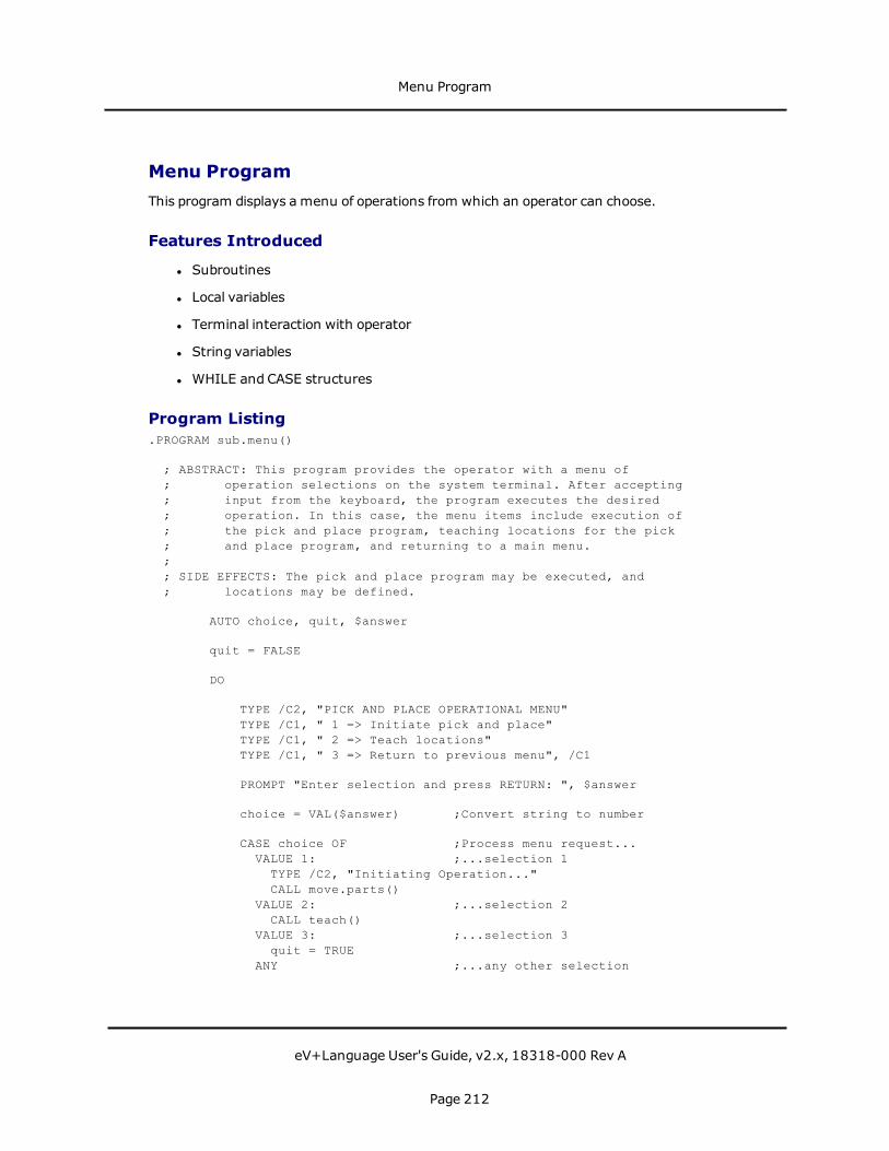
Menu ProgramThis program displays a menu of operations from which an operator can choose.
Features Introduced
l Subroutines
l Local variables
l Terminal interaction with operator
l String variables
l WHILE and CASE structures
Program Listing.PROGRAM sub.menu()
; ABSTRACT: This program provides the operator with a menu of; operation selections on the system terminal. After accepting; input from the keyboard, the program executes the desired; operation. In this case, the menu items include execution of; the pick and place program, teaching locations for the pick; and place program, and returning to a main menu.;; SIDE EFFECTS: The pick and place program may be executed, and; locations may be defined.
AUTO choice, quit, $answer
quit = FALSE
DO
TYPE /C2, "PICK AND PLACE OPERATIONAL MENU"TYPE /C1, " 1 => Initiate pick and place"TYPE /C1, " 2 => Teach locations"TYPE /C1, " 3 => Return to previous menu", /C1
PROMPT "Enter selection and press RETURN: ", $answer
choice = VAL($answer) ;Convert string to number
CASE choice OF ;Process menu request...VALUE 1: ;...selection 1
TYPE /C2, "Initiating Operation..."CALL move.parts()
VALUE 2: ;...selection 2CALL teach()
VALUE 3: ;...selection 3quit = TRUE
ANY ;...any other selection
Menu Program
eV+Language User's Guide, v2.x, 18318-000 Rev A
Page 212
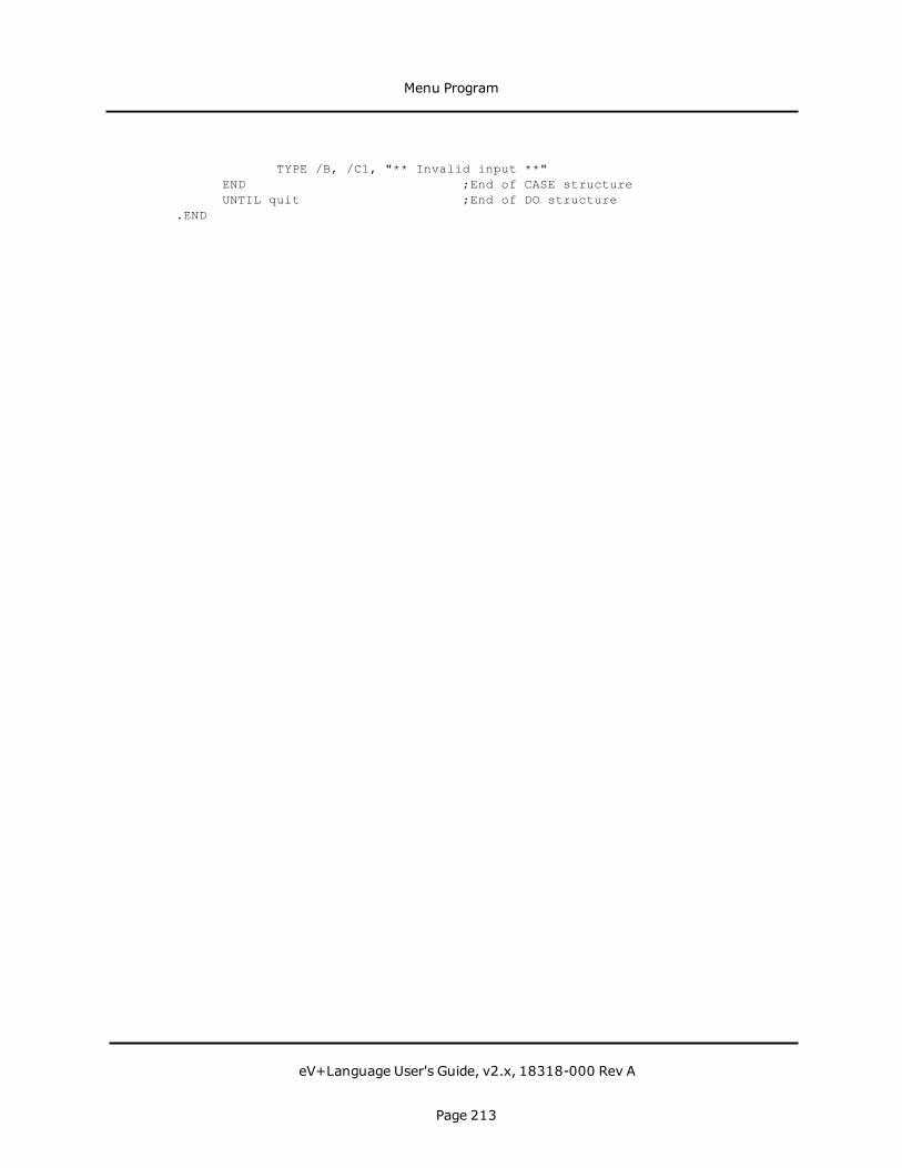
TYPE /B, /C1, "** Invalid input **"END ;End of CASE structureUNTIL quit ;End of DO structure
.END
Menu Program
eV+Language User's Guide, v2.x, 18318-000 Rev A
Page 213


External Encoder DeviceThe following topics are described in this chapter:
Introduction 217Parameters 218Device Setup 219Reading Device Data 220
External Encoder Device
eV+Language User's Guide, v2.x, 18318-000 Rev A
Page 215

External Encoder Device
eV+Language User's Guide, v2.x, 18318-000 Rev A
Page 216
IntroductionThe external-encoder inputs on the system controller are normally used for conveyor belttracking with a robot. However, these inputs can also be used for other sensing applications.In such applications, the DEVICE real-valued function and SETDEVICE program instructionallow the external encoders to be accessed in a more flexible manner than the belt-orientedinstructions and functions.
This appendix describes the use of the DEVICE real-valued function and theSETDEVICEprogram instruction to access the external encoder device.
In general, SETDEVICE allows a scale factor, offset, and limits to be specified for a specifiedexternal encoder unit. The DEVICE real-valued function returns error status, position, orvelocity information for the specified encoder.
Accessing the external encoders via DEVICE and SETDEVICE is independent of any belt-tracking commands or instructions. Setting belt parameters with SETBELT and settingencoder parameters with SETDEVICE have no effect on each other. The only exceptions arethe SETDEVICE initialize command and reset command, which reset all errors for thespecified external encoder, including any belt-related errors.
NOTE: See the eV+ Language Reference Guide. for complete information on the DEVICEreal-valued function and the SETDEVICE program instruction.
Introduction
eV+Language User's Guide, v2.x, 18318-000 Rev A
Page 217
ParametersThe external encoder device type is 0. This means that the type parameter in all DEVICE orSETDEVICE instructions that reference the external encoders must have a value of zero.
The standard controller allows two external encoder units. These units are numbered 0 and1. All DEVICE functions and SETDEVICE instructions that reference the external encodersmust specify one of these unit numbers for the unit parameter.
Parameters
eV+Language User's Guide, v2.x, 18318-000 Rev A
Page 218

Device SetupThe SETDEVICE program instruction allows the external encoders to be initialized andvarious parameters to be set up. The action taken by the SETDEVICE instruction dependsupon the value of the command parameter.
The syntax of the SETDEVICE instruction is
SETDEVICE (0, unit, error, command) p1, p2
The following table describes the valid commands.
Command Description
0 Initialize DeviceThis command sets all scale factors, offsets, and limits to their defaultvalues, as follows: offset = 0; scale factor = 1; no limit checking. Thiscommand also resets any errors for the specified device.Thiscommand should be issued before any other commands for aparticular unit and before using the DEVICE real-valued function forthe unit.
1 Reset DeviceThis command clears any errors associated with this encoder unit. Itdoes not affect the scale factor, offset, or limits.
8 Set Scale FactorThis command sets the position and velocity scale factor for thisencoder unit to the value of parameter p1. The units are millimetersper encoder count. The scale factor must be set before setting theoffset or limits. If the scale factor is changed, the offset and limitvalues will need to be updated.
9 Set Position OffsetThis command sets the position offset for this encoder unit to thevalue of parameter p1. The units are millimeters. The scale factormust be set before setting the offset.
10 Set Position LimitsThis command sets the position limits for the encoder unit to thevalues of optional parameters p1 and p2, which are the lower andupper limits, respectively. If a parameter is omitted, no checking isperformed for that limit. The units are millimeters. The scale factormust be set before setting the limits.
Command Parameter Values
Device Setup
eV+Language User's Guide, v2.x, 18318-000 Rev A
Page 219

Reading Device DataThe DEVICE real-valued function returns information about the encoder error status,position, and velocity. The scale factor, offset, and limits defined by the SETDEVICEinstruction affect the velocity and position values returned.
The syntax for this function is
DEVICE(0, unit, error, select)
The value returned depends upon the value of the select parameter, as described in thefollowing table.
select Description
0 Read Hardware Status
The error status of the encoder unit is returned as a 24-bit value. Thevalid error bits for this device are listed below. The corresponding errorlisted is the one eV+ would report if the error occurred while tracking abelt encoder.
Bit # Bit Mask Corresponding Error Message and Code19 ^H040000 *Lost encoder sync* (-1012)20 ^H080000 *Encoder quadrature error* (-1013)21 ^H100000 *No zero index* (-1011)
Only bit #20, for encoder quadrature error, is detected by the errorparameter of the DEVICE function to generate an error.
1 Read Position
The current position of the encoder (in millimeters) is returned, subjectto the scale factor, offset, and limits defined by the SETDEVICEinstruction. The value returned is computed by:
position = scale*(encoder-offset)position = MAX(position, lower_limit)position = MIN(position, upper_limit)
2 Read Velocity
The current value of the encoder velocity (in millimeters per second) isreturned, subject to the scale factor defined by the SETDEVICEinstruction. The value returned is computed by:
velocity = scale*encoder_velocity
Select Parameter Values
Reading Device Data
eV+Language User's Guide, v2.x, 18318-000 Rev A
Page 220

select Description
3 Read Predicted Position
The predicted position of the encoder (in millimeters) is returned. Theposition is predicted 32 milliseconds in the future, based upon thecurrent position and velocity. The value is scaled the same as thecurrent position described above.
4 Read Latched Position
The position or the encoder (in millimeters) when the last externaltrigger occurred is returned. The LATCHED real-valued function may beused to determinedwhen an external trigger has occurred and a validposition has been recorded.
Reading Device Data
eV+Language User's Guide, v2.x, 18318-000 Rev A
Page 221

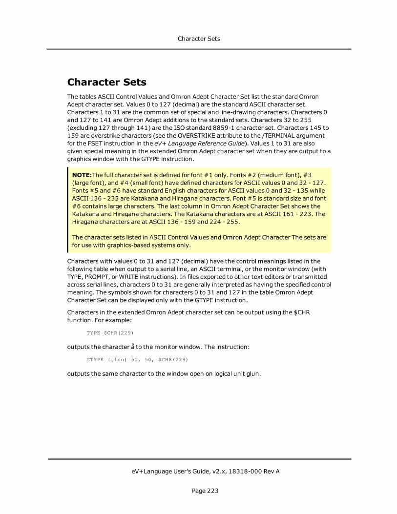
Character SetsThe tables ASCII Control Values and Omron Adept Character Set list the standard OmronAdept character set. Values 0 to 127 (decimal) are the standard ASCII character set.Characters 1 to 31 are the common set of special and line-drawing characters. Characters 0and 127 to 141 are Omron Adept additions to the standard sets. Characters 32 to 255(excluding 127 through 141) are the ISO standard 8859-1 character set. Characters 145 to159 are overstrike characters (see the OVERSTRIKE attribute to the /TERMINAL argumentfor the FSET instruction in the eV+ Language Reference Guide). Values 1 to 31 are alsogiven special meaning in the extended Omron Adept character set when they are output to agraphics window with the GTYPE instruction.
NOTE:The full character set is defined for font #1 only. Fonts #2 (medium font), #3(large font), and#4 (small font) have defined characters for ASCII values 0 and 32 - 127.Fonts #5 and#6 have standard English characters for ASCII values 0 and 32 - 135 whileASCII 136 - 235 are Katakana and Hiragana characters. Font #5 is standard size and font#6 contains large characters. The last column in Omron Adept Character Set shows theKatakana and Hiragana characters. The Katakana characters are at ASCII 161 - 223. TheHiragana characters are at ASCII 136 - 159 and 224 - 255.
The character sets listed in ASCII Control Values and Omron Adept Character The sets arefor use with graphics-based systems only.
Characters with values 0 to 31 and 127 (decimal) have the control meanings listed in thefollowing table when output to a serial line, an ASCII terminal, or the monitor window (withTYPE, PROMPT, or WRITE instructions). In files exported to other text editors or transmittedacross serial lines, characters 0 to 31 are generally interpreted as having the specified controlmeaning. The symbols shown for characters 0 to 31 and 127 in the table Omron AdeptCharacter Set can be displayed only with the GTYPE instruction.
Characters in the extended Omron Adept character set can be output using the $CHRfunction. For example:
TYPE $CHR(229)
outputs the character å to the monitor window. The instruction:
GTYPE (glun) 50, 50, $CHR(229)
outputs the same character to the window open on logical unit glun.
Character Sets
eV+Language User's Guide, v2.x, 18318-000 Rev A
Page 223

Charac-ter
Deci-malValue
He-x.Val-ue
Meaning ofControlCharacter
NUL 000 00 Null
SOH 001 01 Start ofheading
STX 002 02 Start of text
ETX 003 03 End of text
EOT 004 04 End oftransmission
ENQ 005 05 Enquiry
ACK 006 06 Acknowledg-ment
BEL 007 07 Bell
BS 008 08 Backspace
HT 009 09 Horizontaltab
LF 010 0A Line feed
VT 011 0B Vertical tab
FF 012 0C Form feed
CR 013 0D Carriagereturn
SO 014 0E Shift out
SI 015 0F Shift in
ASCII Control Values
Character Sets
eV+Language User's Guide, v2.x, 18318-000 Rev A
Page 224
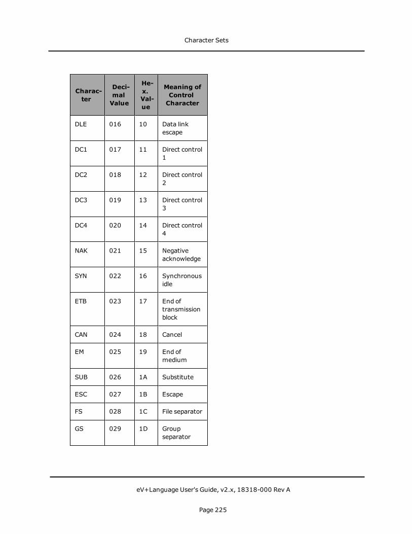
Charac-ter
Deci-malValue
He-x.Val-ue
Meaning ofControlCharacter
DLE 016 10 Data linkescape
DC1 017 11 Direct control1
DC2 018 12 Direct control2
DC3 019 13 Direct control3
DC4 020 14 Direct control4
NAK 021 15 Negativeacknowledge
SYN 022 16 Synchronousidle
ETB 023 17 End oftransmissionblock
CAN 024 18 Cancel
EM 025 19 End ofmedium
SUB 026 1A Substitute
ESC 027 1B Escape
FS 028 1C File separator
GS 029 1D Groupseparator
Character Sets
eV+Language User's Guide, v2.x, 18318-000 Rev A
Page 225
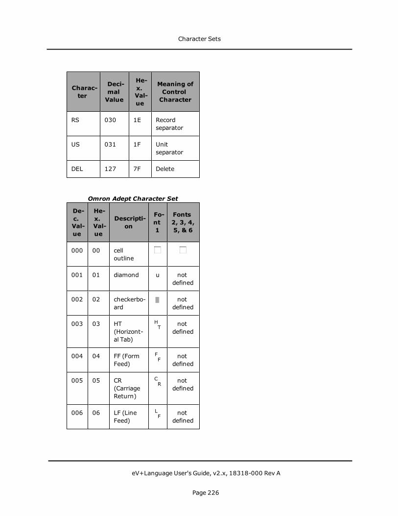
Charac-ter
Deci-malValue
He-x.Val-ue
Meaning ofControlCharacter
RS 030 1E Recordseparator
US 031 1F Unitseparator
DEL 127 7F Delete
De-c.Val-ue
He-x.Val-ue
Descripti-on
Fo-nt1
Fonts2, 3, 4,5, & 6
000 00 celloutline
001 01 diamond u notdefined
002 02 checkerbo-ard
notdefined
003 03 HT(Horizont-al Tab)
HT not
defined
004 04 FF (FormFeed)
FF not
defined
005 05 CR(CarriageReturn)
CR not
defined
006 06 LF (LineFeed)
LF not
defined
Omron Adept Character Set
Character Sets
eV+Language User's Guide, v2.x, 18318-000 Rev A
Page 226

De-c.Val-ue
He-x.Val-ue
Descripti-on
Fo-nt1
Fonts2, 3, 4,5, & 6
007 07 degreesymbol
o notdefined
008 08 plus/minu-s
± notdefined
009 09 NL (Newline)
NL not
defined
010 0A VT(VerticalTab)
VT not
defined
011 0B lowerrightcorner
notdefined
012 0C upperrightcorner
notdefined
013 0D upper leftcorner
notdefined
014 0E lower leftcorner
notdefined
015 0F intersecti-on
notdefined
016 10 scan line3
- notdefined
017 11 scan line6
- notdefined
018 12 scan line9
- notdefined
Character Sets
eV+Language User's Guide, v2.x, 18318-000 Rev A
Page 227

De-c.Val-ue
He-x.Val-ue
Descripti-on
Fo-nt1
Fonts2, 3, 4,5, & 6
019 13 scan line12
- notdefined
020 14 scan line15
- notdefined
021 15 left T-bar notdefined
022 16 right T-bar
notdefined
023 17 bottom T-bar
notdefined
024 18 top T-bar notdefined
025 19 verticalbar
| notdefined
026 1A less thanor equalto
≤ notdefined
027 1B greaterthan orequal to
≥ notdefined
028 1C pi(lowercas-e)
π notdefined
029 1D not equalto
≠ notdefined
030 1E sterling £ notdefined
Character Sets
eV+Language User's Guide, v2.x, 18318-000 Rev A
Page 228

De-c.Val-ue
He-x.Val-ue
Descripti-on
Fo-nt1
Fonts2, 3, 4,5, & 6
031 1F centereddot
· notdefined
032 20 space notdefined
033 21 exclamati-on
! !
034 22 doublequote
" "
035 23 pound # #
036 24 dollar sign $ $
037 25 percent % %
038 26 ampersan-d
& &
039 27 singlequote
' '
040 28 openparen
( (
041 29 closeparen
) )
042 2A asterisk * *
043 2B plus + +
044 2C comma , ,
045 2D hyphen - -
046 2E period . .
Character Sets
eV+Language User's Guide, v2.x, 18318-000 Rev A
Page 229
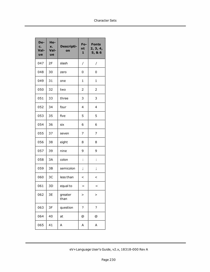
De-c.Val-ue
He-x.Val-ue
Descripti-on
Fo-nt1
Fonts2, 3, 4,5, & 6
047 2F slash / /
048 30 zero 0 0
049 31 one 1 1
050 32 two 2 2
051 33 three 3 3
052 34 four 4 4
053 35 five 5 5
054 36 six 6 6
055 37 seven 7 7
056 38 eight 8 8
057 39 nine 9 9
058 3A colon : :
059 3B semicolon ; ;
060 3C less than < <
061 3D equal to = =
062 3E greaterthan
> >
063 3F question ? ?
064 40 at @ @
065 41 A A A
Character Sets
eV+Language User's Guide, v2.x, 18318-000 Rev A
Page 230

De-c.Val-ue
He-x.Val-ue
Descripti-on
Fo-nt1
Fonts2, 3, 4,5, & 6
066 42 B B B
067 43 C C C
068 44 D D D
069 45 E E E
070 46 F F F
071 47 G G G
072 48 H H H
073 49 I I I
074 4A J J J
075 4B K K K
076 4C L L L
077 4D M M M
078 4E N N N
079 4F O O O
080 50 P P P
081 51 Q Q Q
082 52 R R R
083 53 S S S
084 54 T T T
Character Sets
eV+Language User's Guide, v2.x, 18318-000 Rev A
Page 231
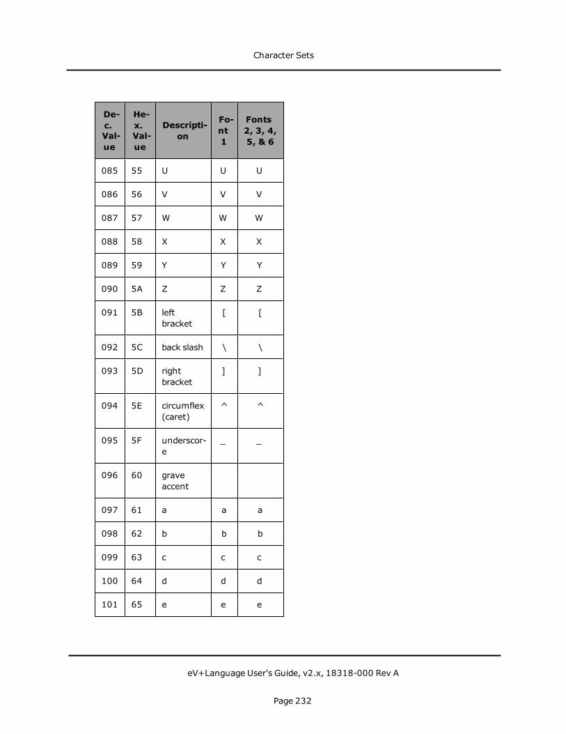
De-c.Val-ue
He-x.Val-ue
Descripti-on
Fo-nt1
Fonts2, 3, 4,5, & 6
085 55 U U U
086 56 V V V
087 57 W W W
088 58 X X X
089 59 Y Y Y
090 5A Z Z Z
091 5B leftbracket
[ [
092 5C back slash \ \
093 5D rightbracket
] ]
094 5E circumflex(caret)
^ ^
095 5F underscor-e
_ _
096 60 graveaccent
097 61 a a a
098 62 b b b
099 63 c c c
100 64 d d d
101 65 e e e
Character Sets
eV+Language User's Guide, v2.x, 18318-000 Rev A
Page 232

De-c.Val-ue
He-x.Val-ue
Descripti-on
Fo-nt1
Fonts2, 3, 4,5, & 6
102 66 f f f
103 67 g g g
104 68 h h h
105 69 i i i
106 6A j j j
107 6B k k k
108 6C l l l
109 6D m m m
110 6E n n n
111 6F o o o
112 70 p p p
113 71 q q q
114 72 r r r
115 73 s s s
116 74 t t t
117 75 u v u
118 76 v v v
119 77 w w w
120 78 x x x
Character Sets
eV+Language User's Guide, v2.x, 18318-000 Rev A
Page 233

De-c.Val-ue
He-x.Val-ue
Descripti-on
Fo-nt1
Fonts2, 3, 4,5, & 6
121 79 y y y
122 7A z z z
123 7B rightbrace
124 7C bar | |
125 7D left brace
126 7E tilde ~ ~
127 7F solid
128 80 copyright © ©
129 81 registeredtrademar-k
® ®
130 82 trademar-k
TM TM
131 83 bullet ·
132 84 superscrip-t +
+
133 85 doublequote(modified)
"
134 86 checkmar-k
135 87 right-pointing
Character Sets
eV+Language User's Guide, v2.x, 18318-000 Rev A
Page 234

De-c.Val-ue
He-x.Val-ue
Descripti-on
Fo-nt1
Fonts2, 3, 4,5, & 6
triangle
136 88 approxim-atelyequalsymbol
≈ ≈
137 89 OEligature
a
138 8A oeligature
i
139 8B beta ß u
140 8C Sigma Σ e
141 8D Omega Ω o
142 8E blank ya
143 8F blank yu
144 90 dotless i ı yo
145 91 graveaccent
Dblnextconson-ant
146 92 acuteaccent
-
147 93 circumflex A
148 94 tilde I
149 95 macron ¯ U
Character Sets
eV+Language User's Guide, v2.x, 18318-000 Rev A
Page 235

De-c.Val-ue
He-x.Val-ue
Descripti-on
Fo-nt1
Fonts2, 3, 4,5, & 6
150 96 breve ˘ E
151 97 dot accent ˙ O
152 98 dieresis ¨ KA
153 99 blank KI
154 9A ring ˚ KU
155 9B cedilla ¸ KE
156 9C blank KO
157 9D hungaru-mlaut
˝ SA
158 9E ogonek ˛ SHI
159 9F caron ˇ SU
160 A0 blank Yensymbol
161 A1 invertedexclamati-on point
¡ Closedcircle
162 A2 cent ¢ Startquote
163 A3 sterling £ Endquote
164 A4 currency ¤ Comma
165 A5 yen ¥ Endsentenc-
Character Sets
eV+Language User's Guide, v2.x, 18318-000 Rev A
Page 236

De-c.Val-ue
He-x.Val-ue
Descripti-on
Fo-nt1
Fonts2, 3, 4,5, & 6
e
166 A6 brokenbar
¦ o
167 A7 section § a
168 A8 dieresis ¨ i
169 A9 copyright © u
170 AA feminineordinal
ª e
171 AB leftguillemot
« o
172 AC logical not ¬ ¬ya
173 AD en dash - yu
174 AE registered ® yo
175 AF macron ¯ Dblnextconson-ant
176 B0 degree ° -
177 B1 plus/minu-s
± A
178 B2 superscrip-t 2
² I
179 B3 superscrip-t 3
³ U
Character Sets
eV+Language User's Guide, v2.x, 18318-000 Rev A
Page 237
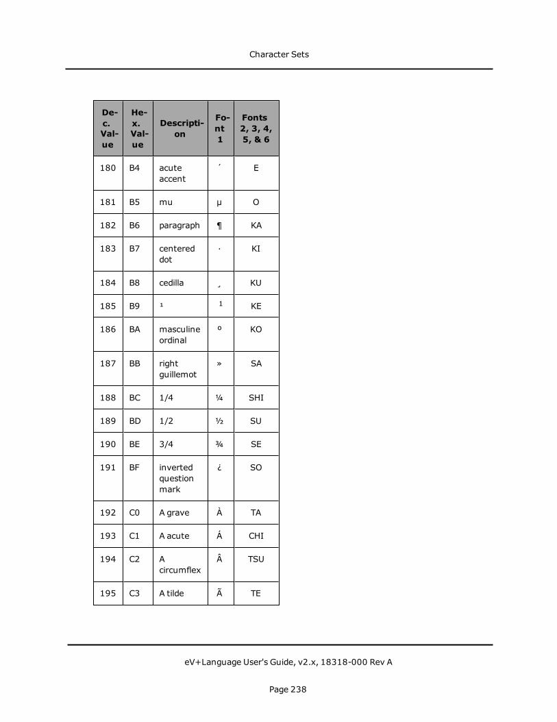
De-c.Val-ue
He-x.Val-ue
Descripti-on
Fo-nt1
Fonts2, 3, 4,5, & 6
180 B4 acuteaccent
´ E
181 B5 mu µ O
182 B6 paragraph ¶ KA
183 B7 centereddot
· KI
184 B8 cedilla ¸ KU
185 B9 ¹ 1 KE
186 BA masculineordinal
º KO
187 BB rightguillemot
» SA
188 BC 1/4 ¼ SHI
189 BD 1/2 ½ SU
190 BE 3/4 ¾ SE
191 BF invertedquestionmark
¿ SO
192 C0 A grave À TA
193 C1 A acute Á CHI
194 C2 Acircumflex
 TSU
195 C3 A tilde à TE
Character Sets
eV+Language User's Guide, v2.x, 18318-000 Rev A
Page 238

De-c.Val-ue
He-x.Val-ue
Descripti-on
Fo-nt1
Fonts2, 3, 4,5, & 6
196 C4 A dieresis Ä TO
197 C5 A ring Å NA
198 C6 AEligature
Æ NI
199 C7 C cedilla Ç NU
200 C8 E grave È NE
201 C9 E acute É NO
202 CA Ecircumflex
Ê HA
203 CB E dieresis Ë HI
204 CC I grave Ì FU
205 CD I acute Í HE
206 CE Icircumflex
Î HO
207 CF I dieresis Ï MA
208 D0 Eth Ð MI
209 D1 N tilde Ñ MU
210 D2 O grave Ò ME
211 D3 O acute Ó MO
212 D4 Ocircumflex
Ô YA
Character Sets
eV+Language User's Guide, v2.x, 18318-000 Rev A
Page 239

De-c.Val-ue
He-x.Val-ue
Descripti-on
Fo-nt1
Fonts2, 3, 4,5, & 6
213 D5 O tilde Õ YU
214 D6 O dieresis Ö YO
215 D7 multiply × RA
216 D8 O slash Ø RI
217 D9 U grave Ù RU
218 DA U acute Ú RE
219 DB Ucircumflex
Û RO
220 DC U dieresis Ü WA
221 DD Y acute Ý N
222 DE Thorn Þ Voicedconson-ant
223 DF Germandouble s
ß Voicedconson-ant-P
224 E0 a grave à SE
225 E1 a acute á SO
226 E2 acircumflex
â TA
227 E3 a tilde ã CHI
228 E4 a dieresis ä TSU
Character Sets
eV+Language User's Guide, v2.x, 18318-000 Rev A
Page 240
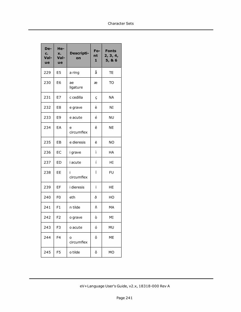
De-c.Val-ue
He-x.Val-ue
Descripti-on
Fo-nt1
Fonts2, 3, 4,5, & 6
229 E5 a ring å TE
230 E6 aeligature
æ TO
231 E7 c cedilla ç NA
232 E8 e grave è NI
233 E9 e acute é NU
234 EA ecircumflex
ê NE
235 EB e dieresis ë NO
236 EC i grave ì HA
237 ED i acute í HI
238 EE icircumflex
î FU
239 EF i dieresis ï HE
240 F0 eth ð HO
241 F1 n tilde ñ MA
242 F2 o grave ò MI
243 F3 o acute ó MU
244 F4 ocircumflex
ô ME
245 F5 o tilde õ MO
Character Sets
eV+Language User's Guide, v2.x, 18318-000 Rev A
Page 241

De-c.Val-ue
He-x.Val-ue
Descripti-on
Fo-nt1
Fonts2, 3, 4,5, & 6
246 F6 o dieresis ö YA
247 F7 divide ÷ YU
248 F8 o slash ø YO
249 F9 u grave ù RA
250 FA u acute ú RI
251 FB ucircumflex
û RU
252 FC u dieresis ü RE
253 FD y acute ý RO
254 FE thorn þ WA
255 FF y dieresis ÿ N
Character Sets
eV+Language User's Guide, v2.x, 18318-000 Rev A
Page 242


Authorized Distributor:
In the interest of product improvement, specifications are subject to change without notice.
Cat. No. I604-E-01
Printed in USA0316
© OMRON Corporation 2016 All Rights Reserved.
OMRON Corporation Industrial Automation Company
OMRON ELECTRONICS LLC2895 Greenspoint Parkway, Suite 200 Hoffman Estates, IL 60169 U.S.A.Tel: (1) 847-843-7900/Fax: (1) 847-843-7787
OMRON ADEPT TECHNOLOGIES, INC. 4550 Norris Canyon Road, Suite 150, San Ramon, CA 94583 U.S.A.Tel: (1) 925-245-3400/Fax: (1) 925-960-0590
Regional HeadquartersOMRON EUROPE B.V.Wegalaan 67-69, 2132 JD HoofddorpThe NetherlandsTel: (31)2356-81-300/Fax: (31)2356-81-388
Contact: industrial.omron.euKyoto, JAPAN
OMRON ASIA PACIFIC PTE. LTD.No. 438A Alexandra Road # 05-05/08 (Lobby 2), Alexandra Technopark, Singapore 119967Tel: (65) 6835-3011/Fax: (65) 6835-2711 OMRON (CHINA) CO., LTD.
Room 2211, Bank of China Tower, 200 Yin Cheng Zhong Road, PuDong New Area, Shanghai, 200120, ChinaTel: (86) 21-5037-2222/Fax: (86) 21-5037-2200
Related Documents