Welcome message from author
This document is posted to help you gain knowledge. Please leave a comment to let me know what you think about it! Share it to your friends and learn new things together.
Transcript

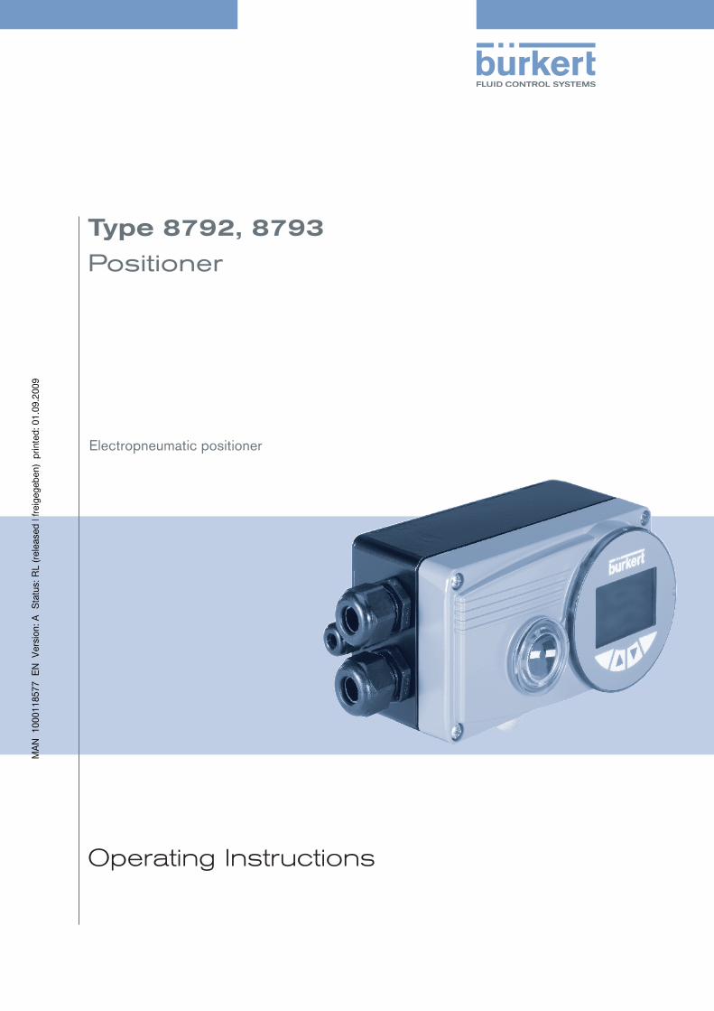
Operating Instructions
Type8792,8793
Positioner
Electropneumatic positioner

We reserve the right to make technical changes without notice.Technische Änderungen vorbehalten.Sous resérve de modification techniques.
© 2009 Bürkert Werke GmbH & Co. KG
Operating Instructions 0908/01_EN-en_00806089
3
Table of conTenTs
General InformatIon and Safety InStructIonS.....................................................................................................7
1.. Operating.Instructions.........................................................................................................................................................8
2.. Authorized.use.........................................................................................................................................................................9
3.. Basic.Safety.Instructions.................................................................................................................................................10
4.. General.Information...........................................................................................................................................................12
deScrIptIon of SyStem....................................................................................................................................................................15
5.. Description.and.features.of.the.positioner............................................................................................................16
6.. Structure.of.the.positioner.............................................................................................................................................20
7.. Type.8792.with.position.controller.function..........................................................................................................22
8.. Type.8793.with.process.controller.function..........................................................................................................26
9.. Interfaces.of.the.positioner............................................................................................................................................30
10.. Technical.Data.......................................................................................................................................................................31
control and dISplay elementS, operatInG modeS............................................................................................35
11.. Control.and.display.elements.......................................................................................................................................36
12.. Operating.modes.................................................................................................................................................................39
13.. Operating.levels....................................................................................................................................................................43
InStallatIon................................................................................................................................................................................................45
14.. Attachment.and.assembly..............................................................................................................................................47
15.. Fluid.connection...................................................................................................................................................................59
16.. Electrical.connection.-.multi-pole.plug.version...................................................................................................61
17.. Electrical.Connection.-.Terminal.Model.for.Cable.Gland...............................................................................66
InItIal Start-up.........................................................................................................................................................................................71
18.. Initial.start-up.........................................................................................................................................................................72
positioner typ 8792, 8793
Type8792,8793
english
Contents

4
Start-up and operatIon of the poSItIon controller type 8792..........................................................77
19.. Starting.up.and.adjusting.the.position.controller...............................................................................................79
20.. Operating.the.position.controller................................................................................................................................85
21.. Configuring.the.auxiliary.functions............................................................................................................................90
Start-up and operatIon of the poSItIon controller type 8793....................................................... 121
22.. Starting.up.and.adjusting.the.process.controller............................................................................................ 123
23.. Operation.of.the.process.controller....................................................................................................................... 145
24.. Auxiliary.functions.for.the.process.controller................................................................................................... 150
operatInG Structure of the poSItIoner................................................................................................................... 167
25.. Operating.structure.positioner.................................................................................................................................. 168
profIBuS-dp.............................................................................................................................................................................................. 175
26.. General.Information........................................................................................................................................................ 176
28.. Safety.Settings.if.the.Bus.Fails................................................................................................................................. 177
30.. Electrical.Connections................................................................................................................................................... 178
31.. Settings.on.the.positioner............................................................................................................................................ 182
32.. Functional.Deviations.from.the.Standard.Model............................................................................................. 186
33.. Configuration.in.the.Profibus-DP.Master............................................................................................................. 187
34.. Bus.status.display............................................................................................................................................................ 189
35.. Configuration.with.Siemens.Step7......................................................................................................................... 190
ServIcInG and trouBleShootInG the poSItIon controller type 8792........................................ 193
36.. Maintenance........................................................................................................................................................................ 194
ServIcInG and trouBleShootInG the proceSS controller type 8793........................................ 197
38.. Maintenance........................................................................................................................................................................ 198
packaGInG, StoraGe, dISpoSal............................................................................................................................................. 203
40.. Packaging.and.Transport.............................................................................................................................................. 204
addItIonal technIcal InformatIon.................................................................................................................................. 205
43.. Selection.criteria.for.continuous.valves............................................................................................................... 206
44.. Properties.of.PID.Controllers..................................................................................................................................... 208
Type8792,8793
english
Contents
5
45.. Adjustment.rules.for.PID.Controllers..................................................................................................................... 213
taBleS for cuStomer-SpecIfIc SettInGS................................................................................................................... 217
46.. Table.for.Your.Settings.on.the.Position.Controller......................................................................................... 218
47.. Table.for.Your.Settings.on.the.Process.Controller.8793............................................................................. 219
maSter code............................................................................................................................................................................................ 221
48.. Master.cod............................................................................................................................................................................ 222
Type8792,8793
english
Contents

6
Type8792,8793
english
Contents

7
conTenTs
1.. OPErATInG.InSTruCTIOnS.........................................................................................................................................................8
1.1.. Symbols.......................................................................................................................................................................................8
2.. AuThOrIzED.uSE..............................................................................................................................................................................9
2.1.. restrictions................................................................................................................................................................................9
2.2.. Predictable.Misuse.................................................................................................................................................................9
3.. BASIC.SAFETY.InSTruCTIOnS...............................................................................................................................................10
4.. GEnErAl.InFOrMATIOn..............................................................................................................................................................12
4.1.. Scope.of.Supply...................................................................................................................................................................12
4.2.. Warranty....................................................................................................................................................................................13
4.3.. Master.code............................................................................................................................................................................13
4.4.. Information.on.the.Internet.............................................................................................................................................13
General Information and Safety Instructions
english
Type8792,8793

8
General InformationSafety Instructions
OperaTinginsTrucTiOns1.
The operating instructions describe the entire life cycle of the device. Keep these instructions in a location which is easily accessible to every user and make these instructions available to every new owner of the device.
WarnInG!
The.operating.instructions.contain.important.safety.information!
Failure to observe these instructions may result in hazardous situations.
The operating instructions must be read and understood.•
symbols1.1.
danGer!
Warns.of.an.immediate.danger!
Failure to observe the warning may result in a fatal or serious injury.•
WarnInG!
Warns.of.a.potentially.dangerous.situation!
Failure to observe the warning may result in serious injuries or death. •
cautIon!
Warns.of.a.possible.danger!
Failure to observe this warning may result in a medium or minor injury. •
note!
Warns.of.damage.to.property!
Failure to observe the warning may result in damage to the device or the equipment. •
indicates important additional information, tips and recommendations which are important for your safety and the flawless functioning of the device.
refers to information in these operating instructions or in other documentation.
designates a procedure that must be carried out. →
english
Type8792,8793Type8792,8793

9
General InformationSafety Instructions
auThOrizeduse2.
Incorrect.use.of.the.positioner.Type.8792.and.Type.8793.can.be.dangerous.to.people,.nearby.equipment.and.the.environment..
The device is designed for the open-loop control and closed-loop control of media.
The device must not be exposed to direct sunlight.•
Pulsating direct voltage (rectified alternating voltage without smoothing) must not be used as power supply.•
During use observe the permitted data, the operating conditions and conditions of use specified in the con-• tract documents and operating instructions, as described in chapter “System Description” - “Technical Data” in this manual and in the valve manual for the respective pneumatically actuated valve.
The device may be used only in conjunction with third-party devices and components recommended and • authorised by Bürkert.
In view of the wide range of possible application cases, check whether the positioner is suitable for the spe-• cific application case and check this out if required.
Correct transportation, correct storage and installation and careful use and maintenance are essential for reli-• able and faultless operation.
Use the positioner Type 8792 and Type 8793 only as intended.•
restrictions2.1.
If exporting the system/device, observe any existing restrictions.
predictableMisuse2.2.
The positioners Type 8792 and Type 8793 must not be used in areas where there is a risk of explosion.•
Do not supply the medium connectors of the system with aggressive or flammable mediums.•
Do not supply the medium connectors with any liquids.•
Do not put any loads on the housing (e.g. by placing objects on it or standing on it).•
Do not make any external modifications to the device housings. Do not paint the housing parts or screws.•
english
Type8792,8793Type8792,8793

10
General InformationSafety Instructions
BasicsafeTyinsTrucTiOns3.These safety instructions do not make allowance for any
contingencies and events which may arise during the installation, operation and maintenance of the devices.•
local safety regulations – the operator is responsible for observing these regulations, also with reference to the • installation personnel.
Danger.–.high.pressure!.
Before loosening the lines and valves, turn off the pressure and vent the lines.•
risk.of.electric.shock!
Before reaching into the device or the equipment,• switch off the power supply and secure to prevent reactivation!
Observe applicable accident prevention and safety regulations for electrical equipment!•
risk.of.burns/risk.of.fire.if.used.continuously.through.hot.device.surface!
Keep the device away from highly flammable substances and media and do not touch with bare hands.•
General.hazardous.situations.
To prevent injury, ensure that:
That the system cannot be activated unintentionally.•
Installation and repair work may be carried out by authorised technicians only and with the appropriate tools.•
After an interruption in the power supply or pneumatic supply, ensure that the process is restarted in a defined • or controlled manner.
The device may be operated only when in perfect condition and in consideration of the operating instructions.•
The general rules of technology apply to application planning and operation of the device.•
note!
Electrostatic.sensitive.components./.modules!
The device contains electronic components which react sensitively to electrostatic discharge (ESD). Contact with electrostatically charged persons or objects is hazardous to these components. In the worst case scenario, they will be destroyed immediately or will fail after start-up.
Observe the requirements in accordance with EN 61340-5-1 and 5-2 to minimise or avoid the possibility of • damage caused by sudden electrostatic discharge!
Also ensure that you do not touch electronic components when the power supply voltage is present! •
english
Type8792,8793Type8792,8793
11
General InformationSafety Instructions
The positioners Type 8792 and Type 8793 were developed with due consideration given to the accepted safety rules and are state-of-the-art. Nevertheless, dangerous situations may occur.
Failure to observe this operating manual and its operating instructions as well as unauthorized tampering with the device release us from any liability and also invalidate the warranty covering the devices and accessories!
english
Type8792,8793Type8792,8793
12
General InformationSafety Instructions
generalinfOrMaTiOn4.
scopeofsupply4.1.
Check immediately upon receipt of the delivery that the contents are not damaged and that the type and scope agree with the delivery note and packing list.
Generally the product package consists of: positioner, type 8792 / 8793 and the associated operating instructions
We will provide you with attachment kits for push drives or swivel actuators as accessories. For the multipole version of the positioners we will provide you with cable connectors as accessories.
If there are any discrepancies, please contact us immediately.
Germany
Contact address:
Bürkert Fluid Control Systems Sales Center Chr.-Bürkert-Str. 13-17 D-74653 Ingelfingen Tel. + 49 (0) 7940 - 10 91 111 Fax + 49 (0) 7940 - 10 91 448 E-mail: [email protected]
International
Contact addresses can be found on the final pages of these operating instructions.
And also on the internet at:
www.burkert.com Bürkert Company Locations
english
Type8792,8793Type8792,8793

13
General InformationSafety Instructions
Warranty4.2.
This document contains no promise of guarantee. Please refer to our general terms of sales and delivery. The war-ranty is only valid if the positioners Type 8792 and Type 8793 are used as intended in accordance with the specified application conditions.
The warranty extends only to defects in the positioners Type 8792 and Type 8793 and their components.
We accept no liability for any kind of collateral damage which could occur due to failure or malfunction of the device.
Mastercode4.3.
Operation of the device can be locked via a freely selectable user code. In addition, there is a non-changeable master code with which you can perform all operator control actions on the device. This 4-digit master code can be found on the last pages of these operating instructions in the chapter entitled “Master code”.
If required, cut out the code and keep it separate from these operating instructions.
informationontheinternet4.4.
The operating instructions and data sheets for Type 8792 and Type 8793 can be found on the Internet at:
www.burkert.com Documentation Type 8792 or Type 8793
There is also complete documentation on CD. The complete operating instructions can be ordered by quoting the following identification number: 804625
english
Type8792,8793Type8792,8793

14
General InformationSafety Instructions
english
Type8792,8793

15
conTenTs
5.. DESCrIPTIOn.AnD.FEATurES.OF.ThE.POSITIOnEr................................................................................................16
5.1.. General.Description............................................................................................................................................................16
5.1.1. Features .....................................................................................................................................................16
5.1.2. Combination with valve types and mounting versions ....................................................................17
5.1.3. Overview of the mounting options.......................................................................................................18
5.2.. Designs.....................................................................................................................................................................................19
5.2.1. Type 8792, positioner with position control function ......................................................................19
5.2.2. Type 8793, positioner with process control function .....................................................................19
6.. STruCTurE.OF.ThE.POSITIOnEr........................................................................................................................................20
6.1.. representation......................................................................................................................................................................20
6.2.. Function.diagram.................................................................................................................................................................21
6.2.1. Diagram illustrating single-acting actuator ........................................................................................21
7.. TYPE.8792.WITh.POSITIOn.COnTrOllEr.FunCTIOn..............................................................................................22
7.1.. Schematic.representation.of.the.position.control.............................................................................................23
7.2.. Properties.of.the.position.controller.software.....................................................................................................24
8.. TYPE.8793.WITh.PrOCESS.COnTrOllEr.FunCTIOn..............................................................................................26
8.1.. Schematic.representation.of.process.control......................................................................................................27
8.2.. Properties.of.the.position.controller.software.....................................................................................................28
9.. InTErFACES.OF.ThE.POSITIOnEr........................................................................................................................................30
10.. TEChnICAl.DATA..............................................................................................................................................................................31
10.1.. Safety.positions.after.failure.of.the.electrical.or.pneumatic.auxiliary.power......................................31
10.2.. Factory.settings.of.the.positioner...............................................................................................................................32
10.3.. Specifications.of.the.Positioner...................................................................................................................................33
10.3.1. Operating Conditions .............................................................................................................................33
10.3.2. Conformity .................................................................................................................................................33
10.3.3. Mechanical data .......................................................................................................................................33
10.3.4. Electrical data ...........................................................................................................................................33
10.3.5. Pneumatic data ........................................................................................................................................34
description of System
English
Types8792,8793
16
Description of System
descripTiOnandfeaTuresOfThe5.pOsiTiOner
generaldescription5.1.
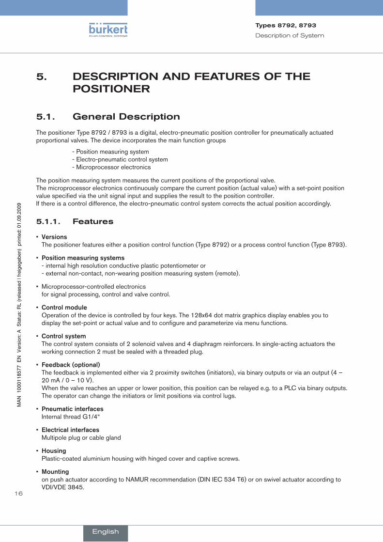
The positioner Type 8792 / 8793 is a digital, electro-pneumatic position controller for pneumatically actuated proportional valves. The device incorporates the main function groups
- Position measuring system - Electro-pneumatic control system - Microprocessor electronics
The position measuring system measures the current positions of the proportional valve. The microprocessor electronics continuously compare the current position (actual value) with a set-point position value specified via the unit signal input and supplies the result to the position controller. If there is a control difference, the electro-pneumatic control system corrects the actual position accordingly.
features5.1.1.
Versions.• The positioner features either a position control function (Type 8792) or a process control function (Type 8793).
Position.measuring.systems.• - internal high resolution conductive plastic potentiometer or - external non-contact, non-wearing position measuring system (remote).
Microprocessor-controlled electronics • for signal processing, control and valve control.
Control.module.• Operation of the device is controlled by four keys. The 128x64 dot matrix graphics display enables you to display the set-point or actual value and to configure and parameterize via menu functions.
Control.system.• The control system consists of 2 solenoid valves and 4 diaphragm reinforcers. In single-acting actuators the working connection 2 must be sealed with a threaded plug.
Feedback.(optional).• The feedback is implemented either via 2 proximity switches (initiators), via binary outputs or via an output (4 – 20 mA / 0 – 10 V). When the valve reaches an upper or lower position, this position can be relayed e.g. to a PLC via binary outputs. The operator can change the initiators or limit positions via control lugs.
Pneumatic.interfaces.• Internal thread G1/4“
Electrical.interfaces.• Multipole plug or cable gland
housing.• Plastic-coated aluminium housing with hinged cover and captive screws.
Mounting.• on push actuator according to NAMUR recommendation (DIN IEC 534 T6) or on swivel actuator according to VDI/VDE 3845.
English
Types8792,8793
17
Description of System
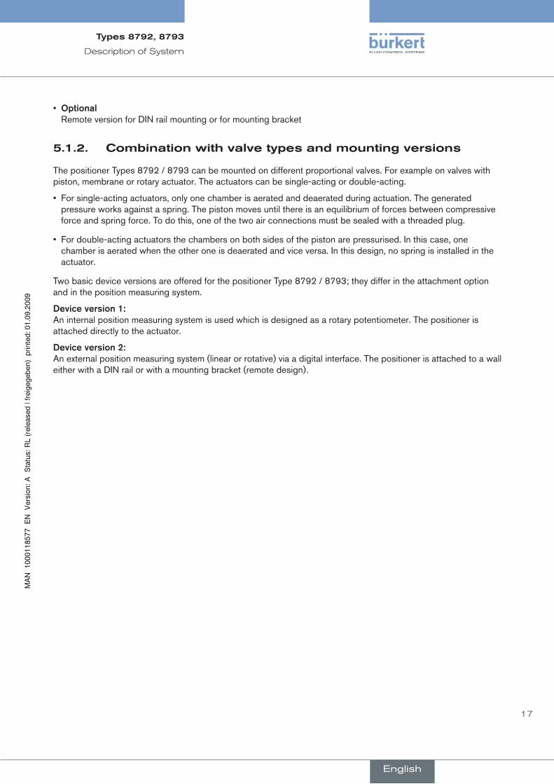
Optional.• Remote version for DIN rail mounting or for mounting bracket
combinationwithvalvetypesandmountingversions5.1.2.
The positioner Types 8792 / 8793 can be mounted on different proportional valves. For example on valves with piston, membrane or rotary actuator. The actuators can be single-acting or double-acting.
For single-acting actuators, only one chamber is aerated and deaerated during actuation. The generated • pressure works against a spring. The piston moves until there is an equilibrium of forces between compressive force and spring force. To do this, one of the two air connections must be sealed with a threaded plug.
For double-acting actuators the chambers on both sides of the piston are pressurised. In this case, one • chamber is aerated when the other one is deaerated and vice versa. In this design, no spring is installed in the actuator.
Two basic device versions are offered for the positioner Type 8792 / 8793; they differ in the attachment option and in the position measuring system.
Device.version.1: An internal position measuring system is used which is designed as a rotary potentiometer. The positioner is attached directly to the actuator.
Device.version.2:.An external position measuring system (linear or rotative) via a digital interface. The positioner is attached to a wall either with a DIN rail or with a mounting bracket (remote design).
English
Types8792,8793
18
Description of System
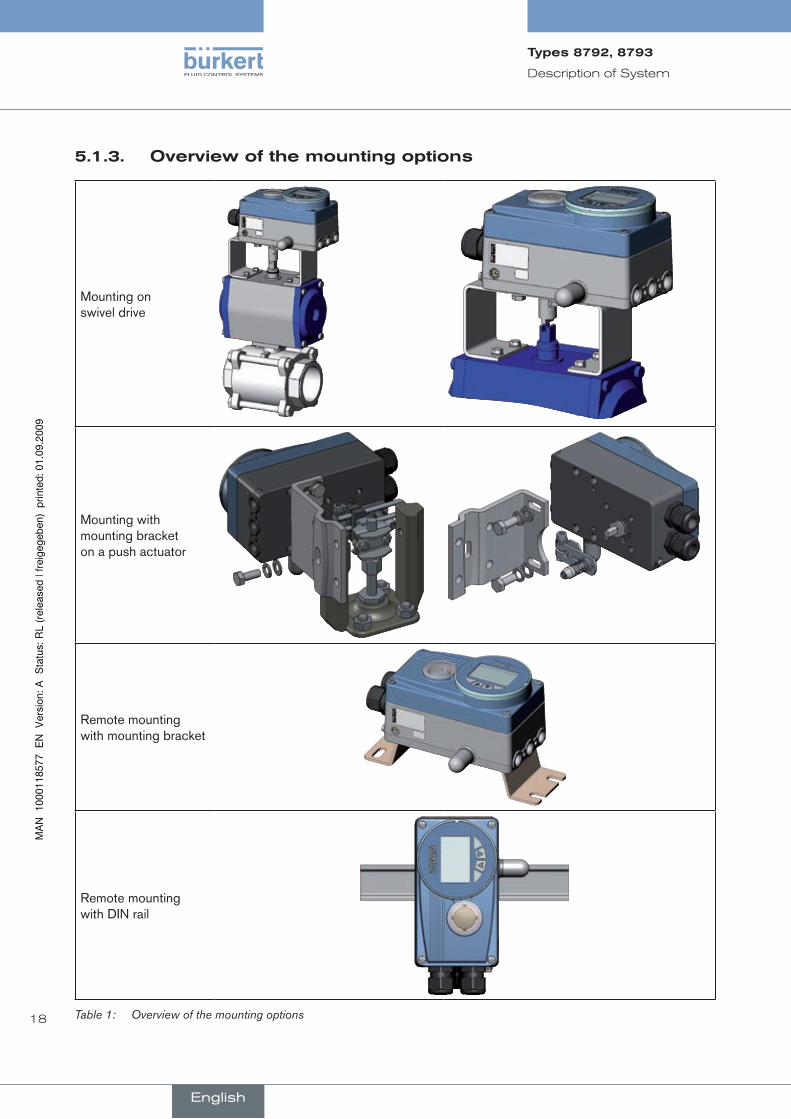
Overviewofthemountingoptions5.1.3.
Mounting on swivel drive
Mounting with mounting bracket on a push actuator
Remote mounting with mounting bracket
Remote mounting with DIN rail
Overview of the mounting optionsTable 1:
English
Types8792,8793

19
Description of System
designs5.2.
Type8792,positionerwithpositioncontrolfunction5.2.1.
The position of the actuator is regulated according to the position set-point value. The position set-point value is specified by an external uniform signal (or via field bus).
Type8793,positionerwithprocesscontrolfunction5.2.2.
The positioner Type 8793 also features a PID controller which, apart from actual position control, can also be used to implement process control (e.g. level, pressure, flow rate, temperature) in the sense of a cascade control.
The positioner Type 8793 is operated with a 128 x 64 dot matrix graphics display and a keypad with 4 keys.
The positioner is linked to a control circuit. The position set-point value of the valve is calculated from the process set-point value and the actual process value via the control parameters (PID controller). The process set-point value can be set by an external signal.
English
Types8792,8793
20
Description of System
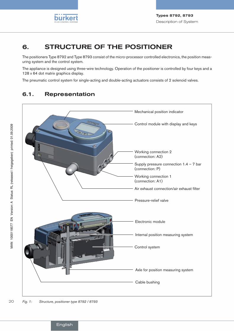
sTrucTureOfThepOsiTiOner6.The positioners Type 8792 and Type 8793 consist of the micro-processor controlled electronics, the position meas-uring system and the control system.
The appliance is designed using three-wire technology. Operation of the positioner is controlled by four keys and a 128 x 64 dot matrix graphics display.
The pneumatic control system for single-acting and double-acting actuators consists of 2 solenoid valves.
representation6.1.
Pressure-relief valve
Mechanical position indicator
Control module with display and keys
Working connection 2 (connection: A2)
Supply pressure connection 1.4 – 7 bar (connection: P)
Working connection 1 (connection: A1)
Air exhaust connection/air exhaust filter
Internal position measuring system
Axle for position measuring system
Cable bushing
Electronic module
Control system
Fig. 1: Structure, positioner type 8792 / 8793
English
Types8792,8793
21
Description of System
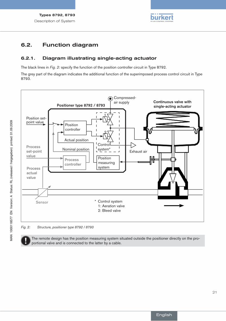
functiondiagram6.2.
diagramillustratingsingle-actingactuator6.2.1.
The black lines in Fig. 2: specify the function of the position controller circuit in Type 8792.
The grey part of the diagram indicates the additional function of the superimposed process control circuit in Type 8793.
* Control system 1: Aeration valve 2: Bleed valve
Compressed-air supply
Position measuring system
Process.controller
Position controller
Control system*
1
2
Process.set-point.value
Process.actual.value
Position set-point value
Exhaust air
Positioner.type.8792./.8793Continuous.valve.with..single-acting.actuator
Sensor
Actual position
Nominal position
Fig. 2: Structure, positioner type 8792 / 8793
The remote design has the position measuring system situated outside the positioner directly on the pro-portional valve and is connected to the latter by a cable.
English
Types8792,8793

22
Description of System
7. Type8792WiThpOsiTiOncOnTrOllerfuncTiOn
The position measuring system records the current position (POS) of the pneumatic actuator. The position controller compares this actual position value with the set-point value (CMD) which is specified as a norm signal. If there is a control difference (Xd1), the actuator is aerated and deaerated via the control system. In this way the position of the actuator is changed until control difference is 0. Z1 represents a disturbance variable.
Valve opening
Continuous valve
Control system Solenoid valves
Position measuring system
Position controller
Position set-point value
CMD Xd1B1
E1PK
Z1
POS
position control circuit
+ -
Position control circuit in Type 8792Fig. 3:
English
Types8792,8793

23
Description of System
schematicrepresentationofthepositioncontrol7.1.
4 –
20
mA
0
– 2
0 m
A
0 –
10
V
0 –
5 V
DIR
.CM
DS
PLT
RN
GC
HA
RA
CT
CU
TOFF
X.T
IME
DIR
.AC
TX
.LIM
IT
X.C
ON
TRO
L
DB
ND
PO
S
CM
D
INP
PO
S
CM
D
TEM
P
INP
UT
Schematic representation of position controlFig. 4:
English
Types8792,8793
24
Description of System
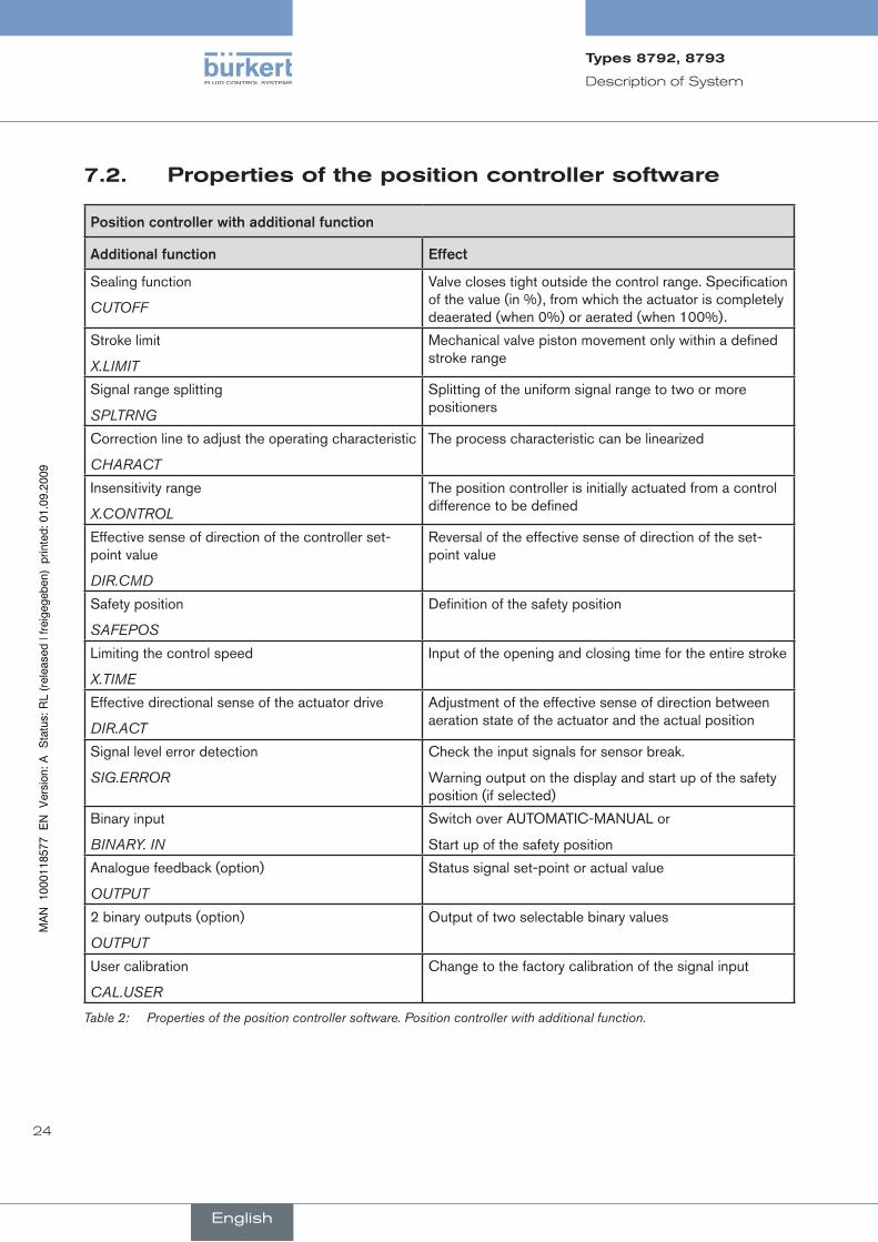
propertiesofthepositioncontrollersoftware7.2.
Position.controller.with.additional.function
Additional.function Effect
Sealing function
CUTOFF
Valve closes tight outside the control range. Specification of the value (in %), from which the actuator is completely deaerated (when 0%) or aerated (when 100%).
Stroke limit
X.LIMIT
Mechanical valve piston movement only within a defined stroke range
Signal range splitting
SPLTRNG
Splitting of the uniform signal range to two or more positioners
Correction line to adjust the operating characteristic
CHARACT
The process characteristic can be linearized
Insensitivity range
X.CONTROL
The position controller is initially actuated from a control difference to be defined
Effective sense of direction of the controller set-point value
DIR.CMD
Reversal of the effective sense of direction of the set-point value
Safety position
SAFEPOS
Definition of the safety position
Limiting the control speed
X.TIME
Input of the opening and closing time for the entire stroke
Effective directional sense of the actuator drive
DIR.ACT
Adjustment of the effective sense of direction between aeration state of the actuator and the actual position
Signal level error detection
SIG.ERROR
Check the input signals for sensor break.
Warning output on the display and start up of the safety position (if selected)
Binary input
BINARY. IN
Switch over AUTOMATIC-MANUAL or
Start up of the safety position
Analogue feedback (option)
OUTPUT
Status signal set-point or actual value
2 binary outputs (option)
OUTPUT
Output of two selectable binary values
User calibration
CAL.USER
Change to the factory calibration of the signal input
Properties of the position controller software. Position controller with additional function.Table 2:
English
Types8792,8793

25
Description of System
hierarchical.control.concept.for.easy.control.on.the.following.levels
Additional.function Effect
Process control On this level switch between AUTOMATIC and MANUAL mode.
Configuration and Parameterization On this level specify certain basic functions during start-up and, if required, configure additional functions
Properties of the position controller software. Position controller with additional function; hierarchical control Table 3: concept.
English
Types8792,8793
26
Description of System
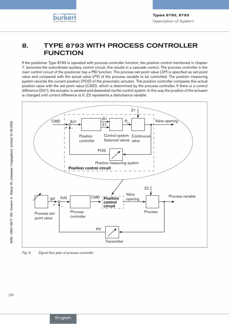
Type8793WiThprOcesscOnTrOller8.funcTiOn
If the positioner Type 8793 is operated with process controller function, the position control mentioned in chapter 7. becomes the subordinate auxiliary control circuit; this results in a cascade control. The process controller in the main control circuit of the positioner has a PID function. The process set-point value (SP) is specified as set-point value and compared with the actual value (PV) of the process variable to be controlled. The position measuring system records the current position (POS) of the pneumatic actuator. The position controller compares this actual position value with the set-point value (CMD), which is determined by the process controller. If there is a control difference (Xd1), the actuator is aerated and deaerated via the control system. In this way the position of the actuator is changed until control difference is 0. Z2 represents a disturbance variable.
Valve opening
Continuous valve
Control system Solenoid valves
Position measuring system
Position controller
CMD Xd1B1E1
PK
Z1
POS
position control circuit
+ -
Process variable
Process
Transmitter
Process controller
Process set-point value
SP Xd2 CMDValve opening
Z2
PV
+ -
position control circuit
Signal flow plan of process controllerFig. 5:
English
Types8792,8793

27
Description of System
schematicrepresentationofprocesscontrol8.1.
4 –
20
mA
0
– 2
0 m
A
0 –
10
V
0 –
5 V
DIR
.CM
DC
HA
RA
CT
CU
TOFF
X.T
IME
DIR
.AC
TX
.LIM
IT
X.C
ON
TRO
L
DB
Dx
PO
S
CM
D
PV
PO
S
CM
D
PV
SP
TEM
P
PV
SC
ALE
P
V
SP
SC
ALE
S
P
SP
P.C
ON
TRO
L PA
RA
ME
TER
S
ETU
P
- +
+-
Q
FILT
ER
Schematic representation of process controlFig. 6:
English
Types8792,8793
28
Description of System
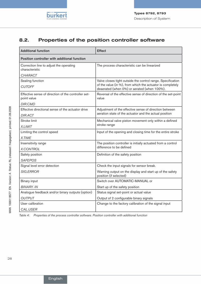
propertiesofthepositioncontrollersoftware8.2.
Additional.function Effect
Position.controller.with.additional.function
Correction line to adjust the operating characteristic
CHARACT
The process characteristic can be linearized
Sealing function
CUTOFF
Valve closes tight outside the control range. Specification of the value (in %), from which the actuator is completely deaerated (when 0%) or aerated (when 100%).
Effective sense of direction of the controller set-point value
DIR.CMD
Reversal of the effective sense of direction of the set-point value
Effective directional sense of the actuator drive
DIR.ACT
Adjustment of the effective sense of direction between aeration state of the actuator and the actual position
Stroke limit
X.LIMIT
Mechanical valve piston movement only within a defined stroke range
Limiting the control speed
X.TIME
Input of the opening and closing time for the entire stroke
Insensitivity range
X.CONTROL
The position controller is initially actuated from a control difference to be defined
Safety position
SAFEPOS
Definition of the safety position
Signal level error detection
SIG.ERROR
Check the input signals for sensor break.
Warning output on the display and start up of the safety position (if selected)
Binary input
BINARY. IN
Switch over AUTOMATIC-MANUAL or
Start up of the safety position
Analogue feedback and/or binary outputs (option)
OUTPUT
Status signal set-point or actual value
Output of 2 configurable binary signals
User calibration
CAL.USER
Change to the factory calibration of the signal input
Properties of the process controller software. Position controller with additional functionTable 4:
English
Types8792,8793
29
Description of System
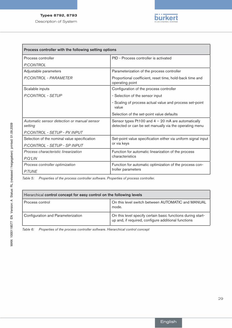
Process.controller.with.the.following.setting.options
Process controller
P.CONTROL
PID - Process controller is activated
Adjustable parameters
P.CONTROL - PARAMETER
Parameterization of the process controller
Proportional coefficient, reset time, hold-back time and operating point
Scalable inputs
P.CONTROL - SETUP
Configuration of the process controller
- Selection of the sensor input
- Scaling of process actual value and process set-point value
Selection of the set-point value defaults
Automatic sensor detection or manual sensor setting
P.CONTROL - SETUP - PV INPUT
Sensor types Pt100 and 4 – 20 mA are automatically detected or can be set manually via the operating menu
Selection of the nominal value specification
P.CONTROL - SETUP - SP INPUT
Set-point value specification either via uniform signal input or via keys
Process characteristic linearization
P.Q‘LIN
Function for automatic linearization of the process characteristics
Process controller optimization
P.TUNE
Function for automatic optimization of the process con-troller parameters
Properties of the process controller software. Properties of process controller.Table 5:
Hierarchical control.concept.for.easy.control.on.the.following.levels
Process control On this level switch between AUTOMATIC and MANUAL mode.
Configuration and Parameterization On this level specify certain basic functions during start-up and, if required, configure additional functions
Properties of the process controller software. Hierarchical control conceptTable 6:
English
Types8792,8793
30
Description of System
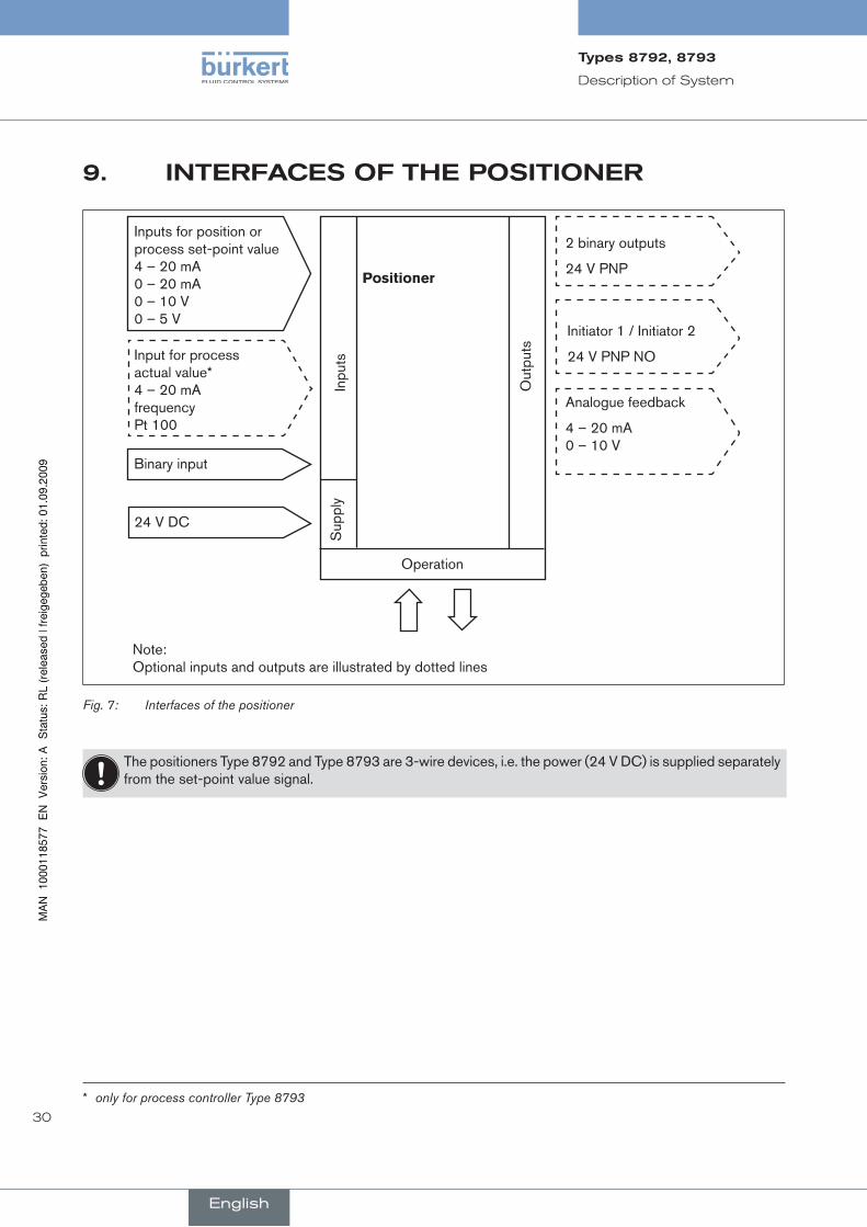
inTerfacesOfThepOsiTiOner9.
Inputs for position or process set-point value 4 – 20 mA 0 – 20 mA 0 – 10 V 0 – 5 V
Input for process actual value* 4 – 20 mA frequency Pt 100
Binary input
24 V DC
positioner
2 binary outputs
24 V PNP
Initiator 1 / Initiator 2
24 V PNP NO
Analogue feedback
4 – 20 mA 0 – 10 V
Inpu
ts
Out
puts
Sup
ply
Operation
Note: Optional inputs and outputs are illustrated by dotted lines
Interfaces of the positionerFig. 7:
The positioners Type 8792 and Type 8793 are 3-wire devices, i.e. the power (24 V DC) is supplied separately from the set-point value signal.
* only for process controller Type 8793
English
Types8792,8793

31
Description of System
TechnicaldaTa10.
10.1. safetypositionsafterfailureoftheelectricalorpneumaticauxiliarypower
In single-acting actuators the safety position depends on the fluid connection of the drive to the working connec-tions A1 or A2 (see Fig. 8: and Fig. 9:)
Actuator.system Designation
Safety.positions.after.failure.of.the.auxiliary.power
electrical pneumatic
up
down
single-acting
Control function A
Connection according to Fig. 8:
downdown
Connection according to
Fig. 9:
up
up
down
single-acting
control function B
Connection according to
Fig. 8:
up upConnection according to
Fig. 9:
down
up
down
double-acting
Control function I
down / up (depending on the con-nection of the control
cables)
not defined
Safety PositionsTable 7:
Sealing working connection 2
Sealing working connection 1
Fig. 8: Connection A1 Fig. 9: Connection A2
English
Types8792,8793
32
Description of System
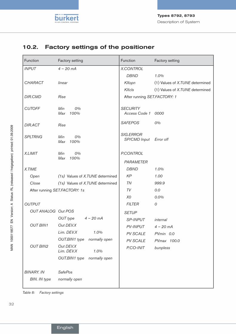
factorysettingsofthepositioner10.2.
Function Factory setting Function Factory setting
INPUT 4 – 20 mA
CHARACT linear
DIR.CMD Rise
CUTOFF Min 0% Max 100%
DIR.ACT Rise
SPLTRNG Min 0% Max 100%
X.LIMIT Min 0% Max 100%
X.TIME
Open (1s) Values of X.TUNE determined
Close (1s) Values of X.TUNE determined
After running SET.FACTORY: 1s
OUTPUT
OUT ANALOG Out POS
OUT type 4 – 20 mA
OUT BIN1 Out DEV.X
Lim. DEV.X 1.0%
OUT.BIN1 type normally open
OUT BIN2 Out DEV.X Lim. DEV.X 1.0%
OUT.BIN1 type normally open
BINARY. IN SafePos
BIN. IN type normally open
X.CONTROL
DBND 1.0%
KXopn (1) Values of X.TUNE determined
KXcls (1) Values of X.TUNE determined
After running SET.FACTORY: 1
SECURITY Access Code 1 0000 SAFEPOS 0%
SIG.ERROR SP/CMD Input Error off
P.CONTROL
PARAMETER
DBND 1.0%
KP 1.00
TN 999.9
TV 0.0
X0 0.0%
FILTER 0
SETUP
SP-INPUT internal
PV-INPUT 4 – 20 mA
PV SCALE PVmin 0.0
PV SCALE PVmax 100.0
P.CO-INIT bunpless
Factory settingsTable 8:
English
Types8792,8793
33
Description of System
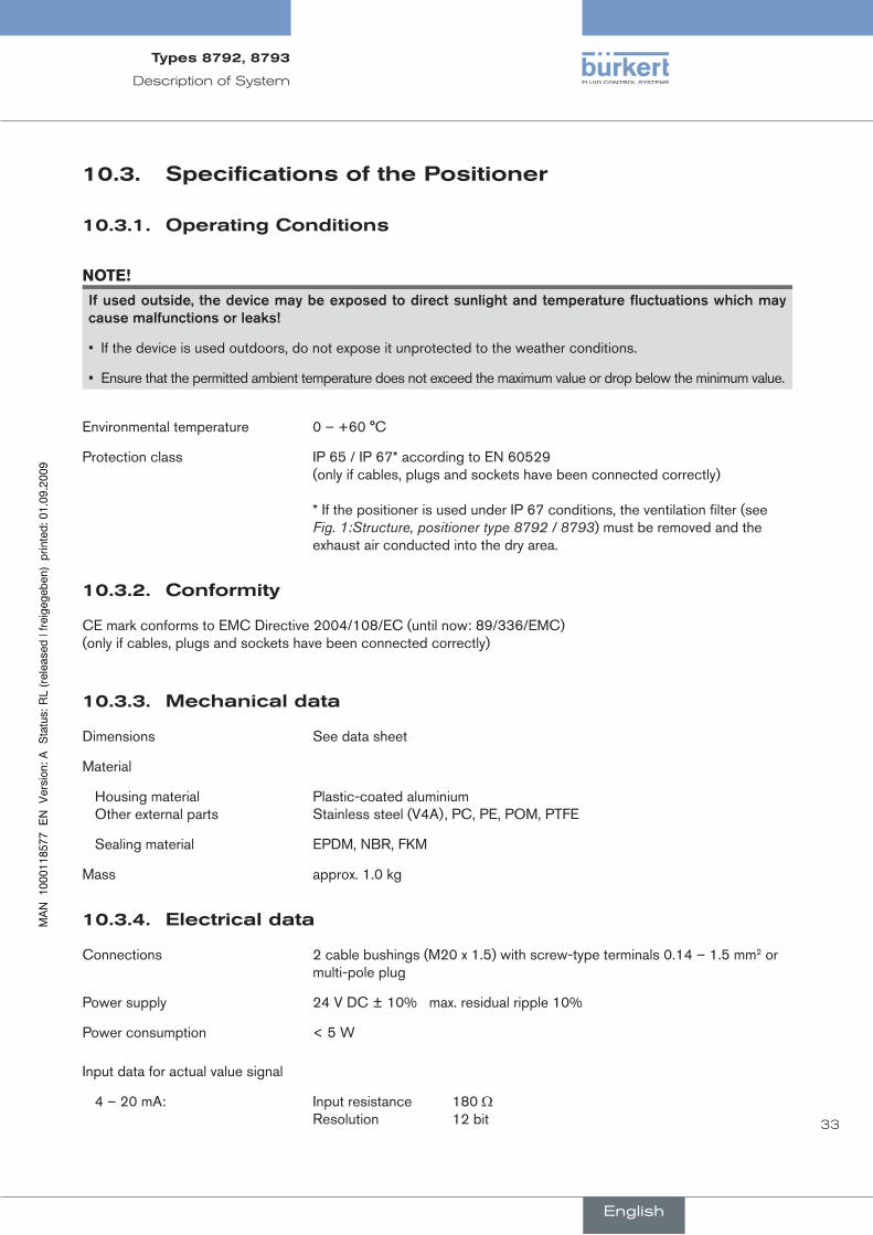
specificationsofthepositioner10.3.
Operatingconditions10.3.1.
note!
If.used.outside,.the.device.may.be.exposed.to.direct.sunlight.and.temperature.fluctuations.which.may.cause.malfunctions.or.leaks!
If the device is used outdoors, do not expose it unprotected to the weather conditions. •
Ensure that the permitted ambient temperature does not exceed the maximum value or drop below the minimum value.•
Environmental temperature 0 – +60 °C
Protection class IP 65 / IP 67* according to EN 60529 (only if cables, plugs and sockets have been connected correctly) * If the positioner is used under IP 67 conditions, the ventilation filter (see Fig. 1:Structure, positioner type 8792 / 8793) must be removed and the exhaust air conducted into the dry area.
conformity10.3.2.
CE mark conforms to EMC Directive 2004/108/EC (until now: 89/336/EMC) (only if cables, plugs and sockets have been connected correctly)
Mechanicaldata10.3.3.
Dimensions See data sheet
Material
Housing material Plastic-coated aluminium Other external parts Stainless steel (V4A), PC, PE, POM, PTFE
Sealing material EPDM, NBR, FKM
Mass approx. 1.0 kg
electricaldata10.3.4.
Connections 2 cable bushings (M20 x 1.5) with screw-type terminals 0.14 – 1.5 mm2 or multi-pole plug
Power supply 24 V DC ± 10% max. residual ripple 10%
Power consumption < 5 W
Input data for actual value signal
4 – 20 mA: Input resistance 180 Ω Resolution 12 bit
English
Types8792,8793
34
Description of System
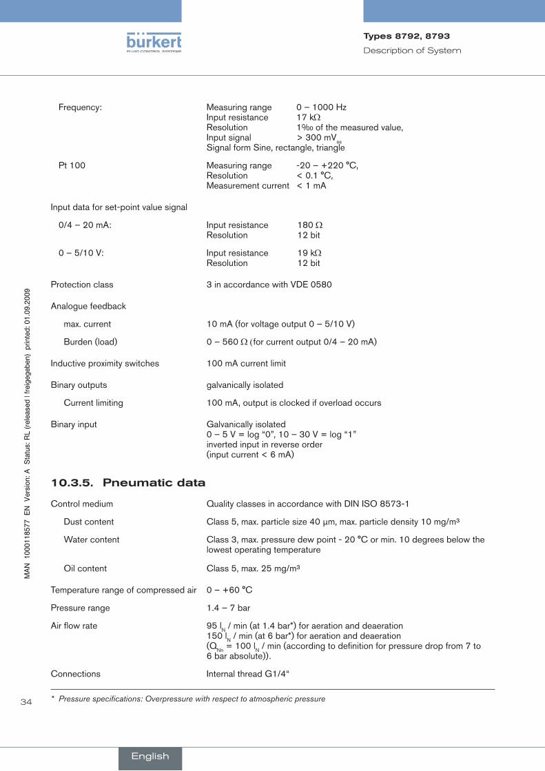
Frequency: Measuring range 0 – 1000 Hz Input resistance 17 kΩ Resolution 1‰ of the measured value, Input signal > 300 mVss Signal form Sine, rectangle, triangle
Pt 100 Measuring range -20 – +220 °C, Resolution < 0.1 °C, Measurement current < 1 mA
Input data for set-point value signal
0/4 – 20 mA: Input resistance 180 Ω Resolution 12 bit
0 – 5/10 V: Input resistance 19 kΩ Resolution 12 bit
Protection class 3 in accordance with VDE 0580
Analogue feedback
max. current 10 mA (for voltage output 0 – 5/10 V)
Burden (load) 0 – 560 Ω (for current output 0/4 – 20 mA)
Inductive proximity switches 100 mA current limit
Binary outputs galvanically isolated
Current limiting 100 mA, output is clocked if overload occurs
Binary input Galvanically isolated 0 – 5 V = log “0”, 10 – 30 V = log “1” inverted input in reverse order (input current < 6 mA)
pneumaticdata10.3.5.
Control medium Quality classes in accordance with DIN ISO 8573-1
Dust content Class 5, max. particle size 40 µm, max. particle density 10 mg/m³
Water content Class 3, max. pressure dew point - 20 °C or min. 10 degrees below the lowest operating temperature
Oil content Class 5, max. 25 mg/m³
Temperature range of compressed air 0 – +60 °C
Pressure range 1.4 – 7 bar
Air flow rate 95 lN / min (at 1.4 bar*) for aeration and deaeration 150 lN / min (at 6 bar*) for aeration and deaeration (QNn = 100 lN / min (according to definition for pressure drop from 7 to 6 bar absolute)).
Connections Internal thread G1/4“
* Pressure specifications: Overpressure with respect to atmospheric pressure
English
Types8792,8793

35
control and display elements, operating modes
conTenTs
11.. COnTrOl.AnD.DISPlAY.ElEMEnTS....................................................................................................................................36
11.1.. Control.and.display.elements.of.the.positioner..................................................................................................36
11.2.. Configuration.of.the.keys................................................................................................................................................37
11.3.. Information.on.the.display..............................................................................................................................................38
12.. OPErATInG.MODES........................................................................................................................................................................39
12.1.. Operating.state.....................................................................................................................................................................39
12.2.. AuTOMATIC.Operating.State.for.Type.8792.........................................................................................................40
12.3.. AuTOMATIC.Operating.State.for.Type.8793.........................................................................................................41
12.4.. MAnuAl.operating.state.................................................................................................................................................42
13.. OPErATInG.lEVElS........................................................................................................................................................................43
13.1.. Switching.between.the.operating.levels.................................................................................................................43
english
Type8792,8793
36
Control and display elements,
operating modes
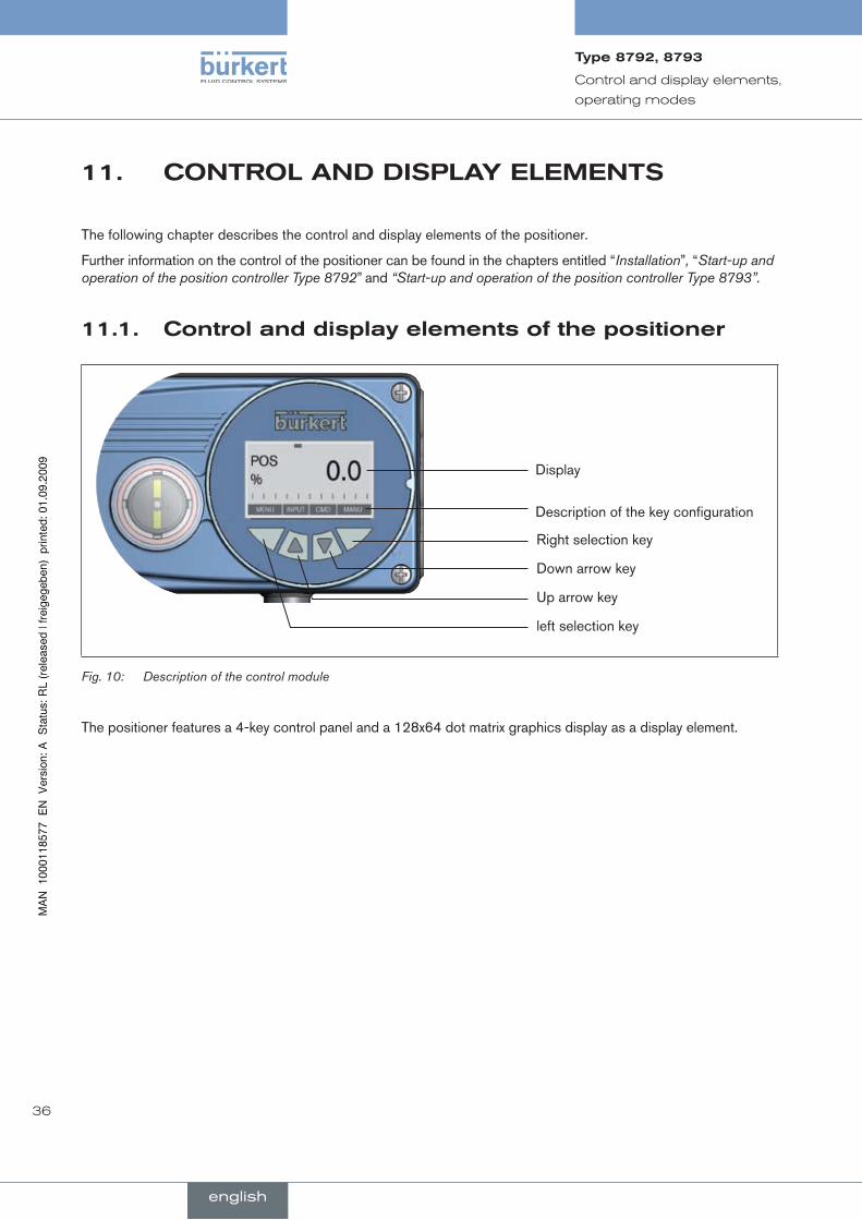
11. cOnTrOlanddisplayeleMenTs
The following chapter describes the control and display elements of the positioner.
Further information on the control of the positioner can be found in the chapters entitled “Installation”, “Start-up and operation of the position controller Type 8792” and “Start-up and operation of the position controller Type 8793”.
controlanddisplayelementsofthepositioner11.1.
Display
Description of the key configuration
Right selection key
Down arrow key
Up arrow key
left selection key
Description of the control moduleFig. 10:
The positioner features a 4-key control panel and a 128x64 dot matrix graphics display as a display element.
english
Type8792,8793
37
Control and display elements,
operating modes
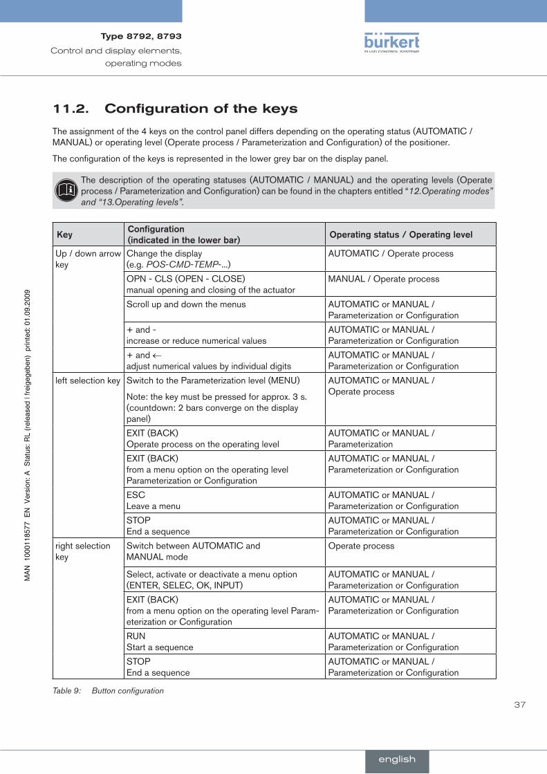
11.2. configurationofthekeys
The assignment of the 4 keys on the control panel differs depending on the operating status (AUTOMATIC / MANUAL) or operating level (Operate process / Parameterization and Configuration) of the positioner.
The configuration of the keys is represented in the lower grey bar on the display panel.
The description of the operating statuses (AUTOMATIC / MANUAL) and the operating levels (Operate process / Parameterization and Configuration) can be found in the chapters entitled “12.Operating modes” and “13.Operating levels”.
KeyConfiguration..(indicated.in.the.lower.bar)
Operating.status./.Operating.level
Up / down arrow key
Change the display (e.g. POS-CMD-TEMP-...)
AUTOMATIC / Operate process
OPN - CLS (OPEN - CLOSE) manual opening and closing of the actuator
MANUAL / Operate process
Scroll up and down the menus AUTOMATIC or MANUAL / Parameterization or Configuration
+ and - increase or reduce numerical values
AUTOMATIC or MANUAL / Parameterization or Configuration
+ and ← adjust numerical values by individual digits
AUTOMATIC or MANUAL / Parameterization or Configuration
left selection key Switch to the Parameterization level (MENU)
Note: the key must be pressed for approx. 3 s. (countdown: 2 bars converge on the display panel)
AUTOMATIC or MANUAL / Operate process
EXIT (BACK) Operate process on the operating level
AUTOMATIC or MANUAL / Parameterization
EXIT (BACK) from a menu option on the operating level Parameterization or Configuration
AUTOMATIC or MANUAL / Parameterization or Configuration
ESC Leave a menu
AUTOMATIC or MANUAL / Parameterization or Configuration
STOP End a sequence
AUTOMATIC or MANUAL / Parameterization or Configuration
right selection key
Switch between AUTOMATIC and MANUAL mode
Operate process
Select, activate or deactivate a menu option (ENTER, SELEC, OK, INPUT)
AUTOMATIC or MANUAL / Parameterization or Configuration
EXIT (BACK) from a menu option on the operating level Param-eterization or Configuration
AUTOMATIC or MANUAL / Parameterization or Configuration
RUN Start a sequence
AUTOMATIC or MANUAL / Parameterization or Configuration
STOP End a sequence
AUTOMATIC or MANUAL / Parameterization or Configuration
Button configurationTable 9:
english
Type8792,8793
38
Control and display elements,
operating modes
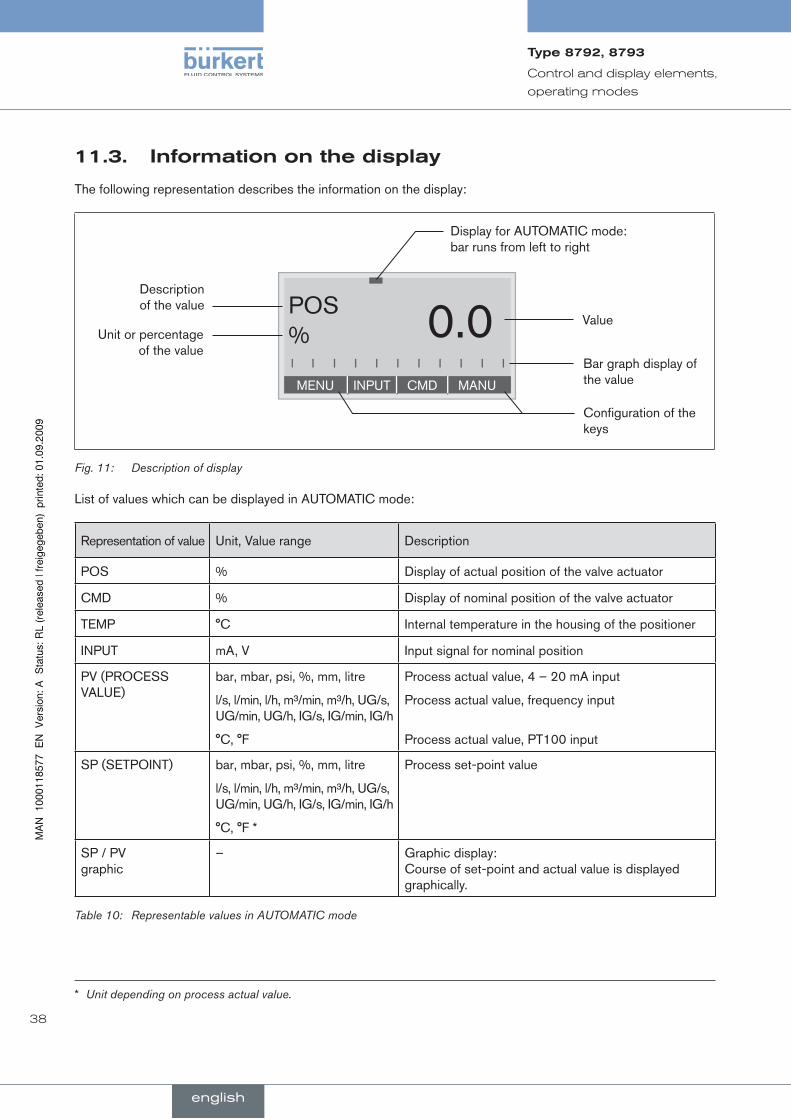
informationonthedisplay11.3.
The following representation describes the information on the display:
MENU INPUT CMD MANU
POS% 0.0
Description of the value
Unit or percentage of the value
Display for AUTOMATIC mode: bar runs from left to right
Value
Bar graph display of the value
Configuration of the keys
Description of displayFig. 11:
List of values which can be displayed in AUTOMATIC mode:
Representation of value Unit, Value range Description
POS % Display of actual position of the valve actuator
CMD % Display of nominal position of the valve actuator
TEMP °C Internal temperature in the housing of the positioner
INPUT mA, V Input signal for nominal position
PV (PROCESS VALUE)
bar, mbar, psi, %, mm, litre
l/s, l/min, l/h, m³/min, m³/h, UG/s, UG/min, UG/h, IG/s, IG/min, IG/h
°C, °F
Process actual value, 4 – 20 mA input
Process actual value, frequency input
Process actual value, PT100 input
SP (SETPOINT) bar, mbar, psi, %, mm, litre
l/s, l/min, l/h, m³/min, m³/h, UG/s, UG/min, UG/h, IG/s, IG/min, IG/h
°C, °F *
Process set-point value
SP / PV graphic
– Graphic display: Course of set-point and actual value is displayed graphically.
Representable values in AUTOMATIC modeTable 10:
* Unit depending on process actual value.
english
Type8792,8793
39
Control and display elements,
operating modes
12. OperaTingMOdes
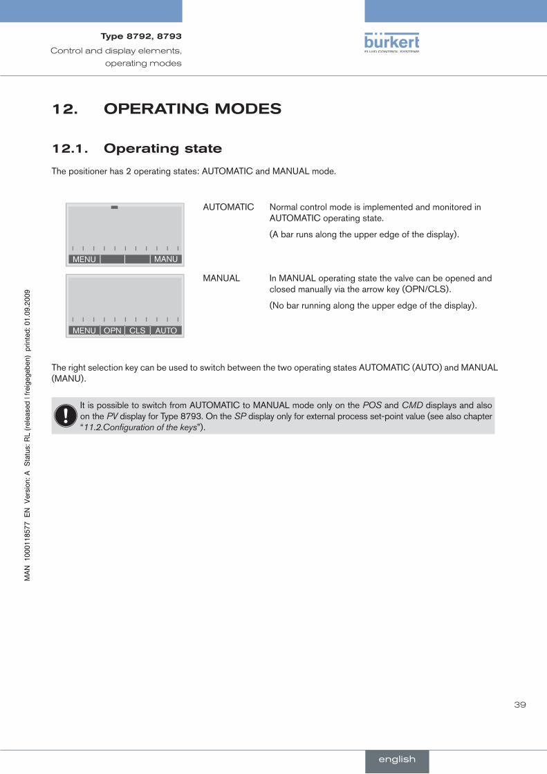
Operatingstate12.1.
The positioner has 2 operating states: AUTOMATIC and MANUAL mode.
MANUMENU
AUTOMATIC Normal control mode is implemented and monitored in AUTOMATIC operating state.
(A bar runs along the upper edge of the display).
AUTOMENU OPN CLS
MANUAL In MANUAL operating state the valve can be opened and closed manually via the arrow key (OPN/CLS).
(No bar running along the upper edge of the display).
The right selection key can be used to switch between the two operating states AUTOMATIC (AUTO) and MANUAL (MANU).
It is possible to switch from AUTOMATIC to MANUAL mode only on the POS and CMD displays and also on the PV display for Type 8793. On the SP display only for external process set-point value (see also chapter “11.2.Configuration of the keys”).
english
Type8792,8793
40
Control and display elements,
operating modes
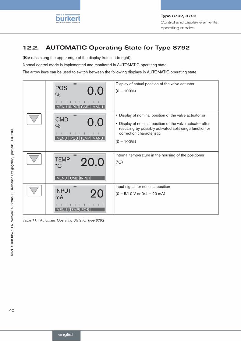
auTOMaTicOperatingstateforType879212.2.
(Bar runs along the upper edge of the display from left to right)
Normal control mode is implemented and monitored in AUTOMATIC operating state.
The arrow keys can be used to switch between the following displays in AUTOMATIC operating state:
MENU INPUT CMD MANU
POS% 0.0
Display of actual position of the valve actuator
(0 – 100%)
MENU POS TEMP MANU
CMD% 0.0
Display of nominal position of the valve actuator or•
Display of nominal position of the valve actuator after • rescaling by possibly activated split range function or correction characteristic
(0 – 100%)
MENU CMD INPUT
TEMP*C 20.0
Internal temperature in the housing of the positioner
(°C)
MENU TEMP POS
INPUTmA 20
Input signal for nominal position
(0 – 5/10 V or 0/4 – 20 mA)
Automatic Operating State for Type 8792Table 11:
english
Type8792,8793
41
Control and display elements,
operating modes
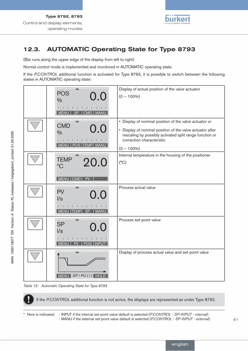
auTOMaTicOperatingstateforType879312.3.
(Bar runs along the upper edge of the display from left to right)
Normal control mode is implemented and monitored in AUTOMATIC operating state.
If the P.CONTROL additional function is activated for Type 8793, it is possible to switch between the following states in AUTOMATIC operating state:
MENU SP CMD MANU
POS% 0.0
Display of actual position of the valve actuator
(0 – 100%)
MENU POS TEMP MANU
CMD% 0.0
Display of nominal position of the valve actuator or•
Display of nominal position of the valve actuator after • rescaling by possibly activated split range function or correction characteristic
(0 – 100%)
MENU CMD PV
TEMP*C 20.0
Internal temperature in the housing of the positioner
(°C)
MENU TEMP SP MANU
PVl/s 0.0
Process actual value
MENU PV POS INPUT*
SPl/s 0.0
Process set-point value
MENU HOLDSP / PU ( t )
Display of process actual value and set-point value
Automatic Operating State for Type 8793Table 12:
If the P.CONTROL additional function is not active, the displays are represented as under Type 8792.
* Here is indicated: - INPUT if the internal set-point value default is selected (P.CONTROL - SP-INPUT - internal). - MANU if the external set-point value default is selected (P.CONTROL - SP-INPUT - external).
english
Type8792,8793

42
Control and display elements,
operating modes
Manualoperatingstate12.4.
(no bar running along upper edge of display)
In MANUAL operating state the valve can be opened and closed manually via the arrow keys.
Meaning of the arrow keys in MANUAL operating state:
Press the up arrow key:
Aerate the actuator
Control function A (SFA): Valve opens Control function B (SFB): Valve closes Control function I (SFI): Connection 2.1 aerated
Press the down arrow key:
Deaerate the actuator
Control function A (SFA): Valve closes Control function B (SFB): Valve opens Control function I (SFI): Connection 2.2 aerated
Meaning of the arrow keys in MANUAL operating stateTable 13:
SFA: Actuator spring force closing
SFB: Actuator spring force opening
SFI: Actuator double-acting
english
Type8792,8793
43
Control and display elements,
operating modes
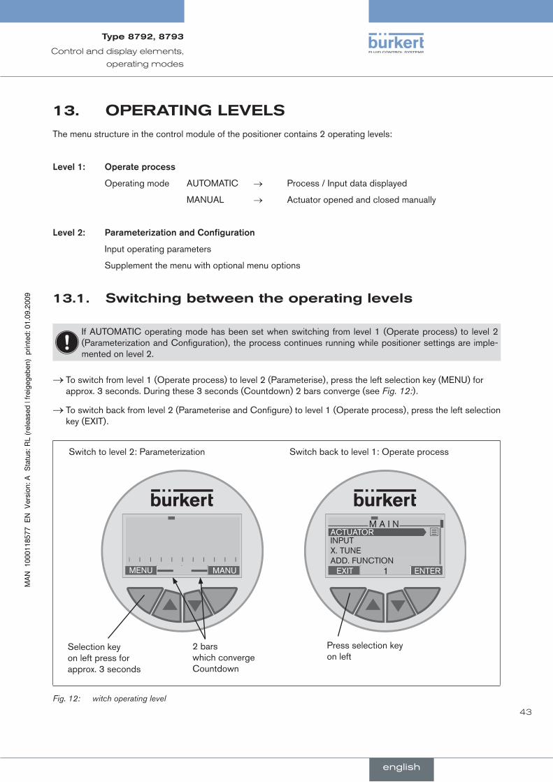
13. OperaTinglevelsThe menu structure in the control module of the positioner contains 2 operating levels:
level.1:. . Operate.process
Operating mode AUTOMATIC → Process / Input data displayed
MANUAL → Actuator opened and closed manually
level.2:. . Parameterization.and.Configuration
Input operating parameters
Supplement the menu with optional menu options
switchingbetweentheoperatinglevels13.1.
If AUTOMATIC operating mode has been set when switching from level 1 (Operate process) to level 2 (Parameterization and Configuration), the process continues running while positioner settings are imple-mented on level 2.
To switch from level 1 (Operate process) to level 2 (Parameterise), press the left selection key (MENU) for →approx. 3 seconds. During these 3 seconds (Countdown) 2 bars converge (see Fig. 12:).
To switch back from level 2 (Parameterise and Configure) to level 1 (Operate process), press the left selection →key (EXIT).
MENU MANU
Selection key on left press for approx. 3 seconds
2 bars which converge Countdown
EXIT ENTER1
M A I NACTUATORINPUT X. TUNE ADD. FUNCTION
Switch to level 2: Parameterization Switch back to level 1: Operate process
Press selection key on left
Fig. 12: witch operating level
english
Type8792,8793

44
Control and display elements,
operating modes
english
Type8792,8793

45
Type8792,8793
english
conTenTs
14.. ATTAChMEnT.AnD.ASSEMBlY.................................................................................................................................................47
14.1.. Safety.Instructions:.............................................................................................................................................................47
14.2.. Attachment.to.a.proportional.valve.with.push.drives.according.to.nAMur.......................................48
14.2.1. Attachment kit for push drives (serial no. 787 215)........................................................................48
14.2.2. Installation .................................................................................................................................................49
14.2.3. Attaching mounting bracket ..................................................................................................................51
14.2.4. Aligning lever mechanism ......................................................................................................................52
14.3.. Attachment.to.a.proportional.valve.with.swivel.actuator...............................................................................53
14.3.1. Mounting kit on swivel actuator (part no. 787338) .........................................................................53
14.3.2. Installation .................................................................................................................................................53
14.4.. remote.operation.with.external.position.measuring.system......................................................................56
14.4.1. Mounting accessories ............................................................................................................................56
14.4.2. Connection and start-up of the Remote Sensor Type 8798 ........................................................57
14.4.3. Connection and start-up via a 4 – 20 mA path sensor (for type 8793 remote model only) .58
15.. FluID.COnnECTIOn.......................................................................................................................................................................59
15.1.. Safety.instructions..............................................................................................................................................................59
16.. ElECTrICAl.COnnECTIOn.-.MulTI-POlE.PluG.VErSIOn....................................................................................61
16.1.. Type.8792.-.designation.of.the.circular.connectors.........................................................................................61
16.2.. Connection.of.the.position.controller.Type.8792...............................................................................................62
16.2.1. Input signals of the control centre (e.g. PLC) - M12, 8-pole plug ...............................................62
16.2.2. Output signals to the control centre (e.g. PLC) - M 12, 8-pole plug (required for analogue output option only) ..................................................................................................................................62
16.2.3. Output signals to the control centre (e.g. PLC) - M8, 4-pole socket (for binary outputs option only) ............................................................................................................................................................63
16.2.4. Operating voltage - M12, 8-pole circular connector .....................................................................63
16.3.. Type.8793.-.designation.of.the.circular.connectors.and.contacts............................................................64
16.4.. Connecting.the.process.controller.8793.................................................................................................................65
16.4.1. Plug assignments of the process actual value input (M8 circular plug) .....................................65
17.. ElECTrICAl.COnnECTIOn.-.TErMInAl.MODEl.FOr.CABlE.GlAnD..............................................................66
Installation
46
Installation
Type8792,8793
english
17.1.. Connection.board.of.the.positioner.with.screw-type.terminals.................................................................66
17.2.. Terminal.Assignment.for.Cable.Gland.-.Position.Controller.Type.8792................................................67
17.2.1. Input signals from the control centre (e.g. PLC) ..............................................................................67
17.2.2. Output signals to the control centre (e.g. PLC) (required for Analogue output and/or Binary output option only) ..................................................................................................................................67
17.2.3. Operating voltage ....................................................................................................................................68
17.2.4. Connecting the external position measuring system (for remote model only) ..........................68
17.3.. Terminal.Assignment.for.Cable.Gland.-.Position.Controller.Type.8793................................................69
17.3.1. Terminal assignments of the process actual value input ................................................................69
47
Installation
Type8792,8793
english
aTTachMenTandasseMBly14.
The dimensions of the positioner and the different device versions can be found on the data sheet.
safetyinstructions:14.1.
WarnInG!
risk.of.injury.from.improper.installation!
Installation may be carried out by authorised technicians only and with the appropriate tools!•
risk.of.injury.from.unintentional.activation.of.the.system.and.an.uncontrolled.restart!
Secure system from unintentional activation.•
Following assembly, ensure a controlled restart.•
48
Installation
Type8792,8793
english
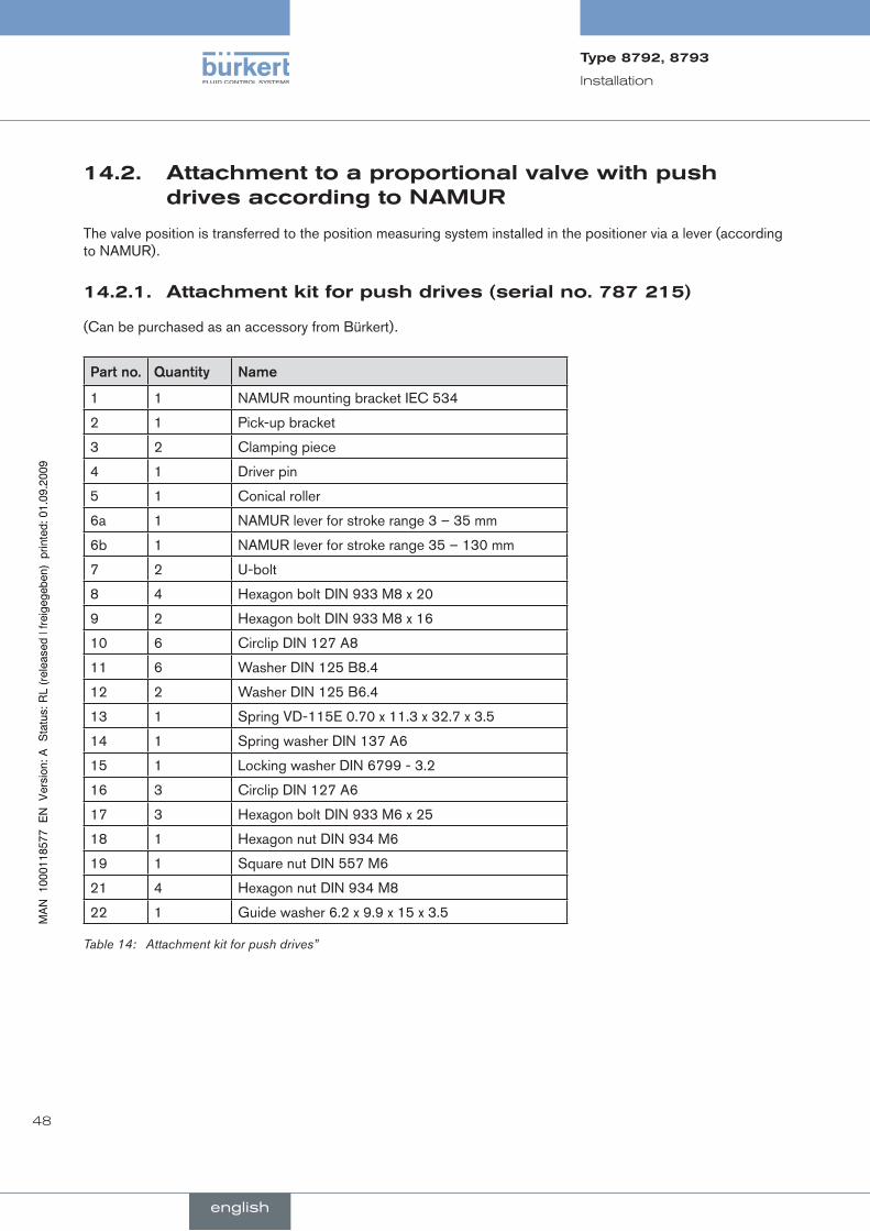
14.2. attachmenttoaproportionalvalvewithpushdrivesaccordingtonaMur
The valve position is transferred to the position measuring system installed in the positioner via a lever (according to NAMUR).
attachmentkitforpushdrives(serialno.787215)14.2.1.
(Can be purchased as an accessory from Bürkert).
Part.no. Quantity name
1 1 NAMUR mounting bracket IEC 534
2 1 Pick-up bracket
3 2 Clamping piece
4 1 Driver pin
5 1 Conical roller
6a 1 NAMUR lever for stroke range 3 – 35 mm
6b 1 NAMUR lever for stroke range 35 – 130 mm
7 2 U-bolt
8 4 Hexagon bolt DIN 933 M8 x 20
9 2 Hexagon bolt DIN 933 M8 x 16
10 6 Circlip DIN 127 A8
11 6 Washer DIN 125 B8.4
12 2 Washer DIN 125 B6.4
13 1 Spring VD-115E 0.70 x 11.3 x 32.7 x 3.5
14 1 Spring washer DIN 137 A6
15 1 Locking washer DIN 6799 - 3.2
16 3 Circlip DIN 127 A6
17 3 Hexagon bolt DIN 933 M6 x 25
18 1 Hexagon nut DIN 934 M6
19 1 Square nut DIN 557 M6
21 4 Hexagon nut DIN 934 M8
22 1 Guide washer 6.2 x 9.9 x 15 x 3.5
Table 14: Attachment kit for push drives”
49
Installation
Type8792,8793
english
installation14.2.2.
WarnInG!
risk.of.injury.from.improper.installation!
Installation may be carried out by authorised technicians only and with the appropriate tools!•
risk.of.injury.from.unintentional.activation.of.the.system.and.an.uncontrolled.restart!
Secure system from unintentional activation.•
Following assembly, ensure a controlled restart.•
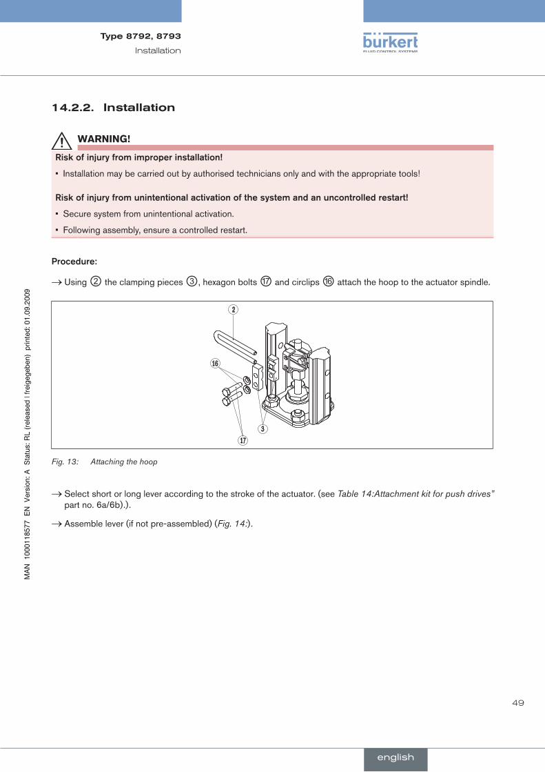
Procedure:
Using → ② the clamping pieces ③, hexagon bolts ⑰ and circlips ⑯ attach the hoop to the actuator spindle.
317
2
16
Attaching the hoopFig. 13:
Select short or long lever according to the stroke of the actuator. (see → Table 14:Attachment kit for push drives” part no. 6a/6b).).
Assemble lever (if not pre-assembled) ( → Fig. 14:).

50
Installation
Type8792,8793
english
17
16
12
6
19 18
14
12
22
5
4
13
15
Fig. 14: Assembling the lever
The gap between the driver pin and the axle should be the same as the drive stroke. As a result, the lever has a swivel range of 60° (see Fig. 15:).
Slewing.range.of.the.position.measuring.system:..The maximum slewing range of the position measuring system is 120°.
Swivel.range.of.the.lever:..To ensure that the position measuring system operates at a good resolution, the swivel range of the lever must be at least 60°.
The swivel movement of the lever must be within the position measuring system slewing range of 120°.
The scale printed on the lever is not relevant.
60°
Sw
ivel
rang
e of
the
leve
r The swivel movement of the lever must be within the position measuring system slewing range of 120 °.
Fig. 15: Slewing range of the lever
Attach lever to the axle of the positioner and screw tight. →
51
Installation
Type8792,8793
english
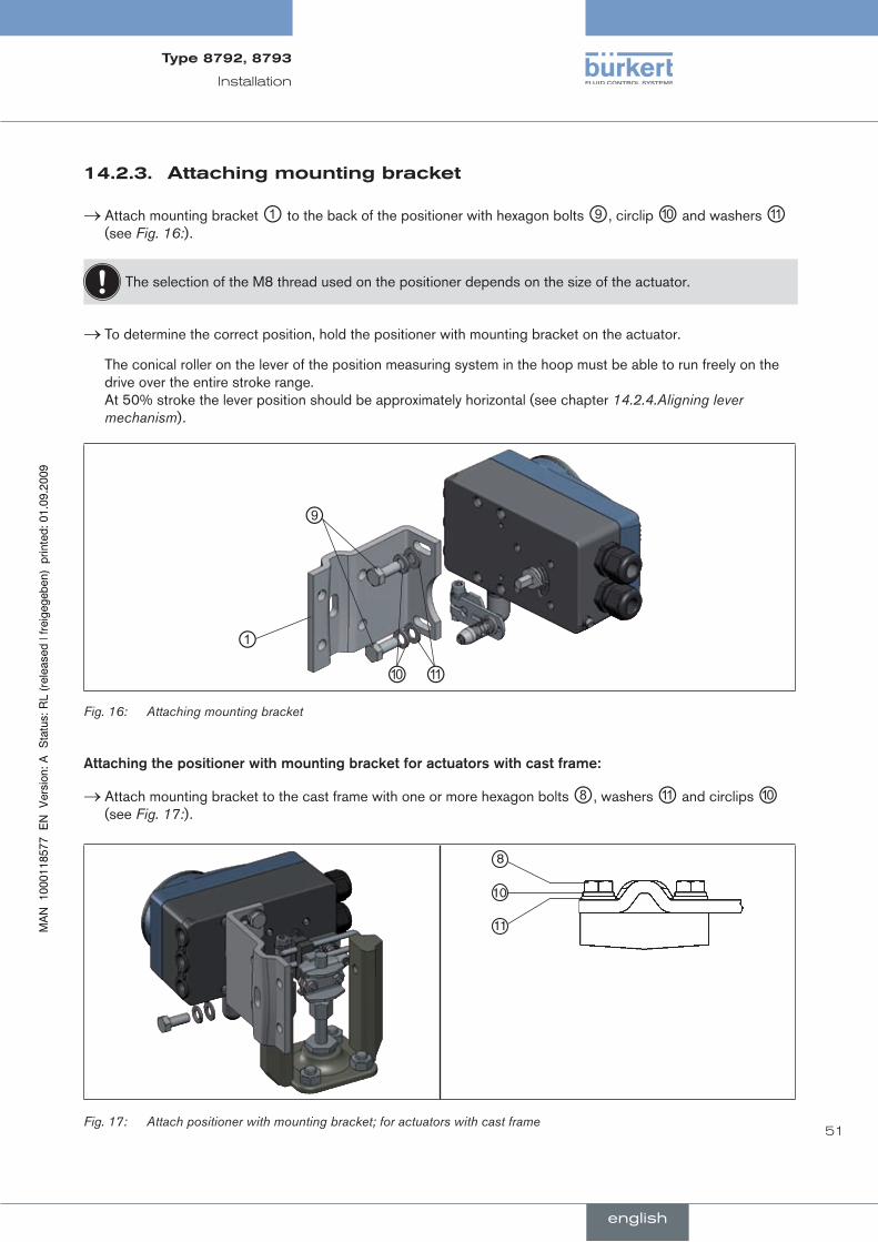
attachingmountingbracket14.2.3.
Attach mounting bracket → ① to the back of the positioner with hexagon bolts ⑨, circlip ⑩ and washers ⑪ (see Fig. 16:).
The selection of the M8 thread used on the positioner depends on the size of the actuator.
To determine the correct position, hold the positioner with mounting bracket on the actuator. →
The conical roller on the lever of the position measuring system in the hoop must be able to run freely on the drive over the entire stroke range. At 50% stroke the lever position should be approximately horizontal (see chapter 14.2.4.Aligning lever mechanism).
①
⑨
⑩ ⑪Fig. 16: Attaching mounting bracket
Attaching.the.positioner.with.mounting.bracket.for.actuators.with.cast.frame:
Attach mounting bracket to the cast frame with one or more hexagon bolts → ⑧, washers ⑪ and circlips ⑩ (see Fig. 17:).
8
10
11
Fig. 17: Attach positioner with mounting bracket; for actuators with cast frame
52
Installation
Type8792,8793
english
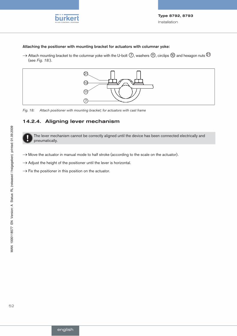
Attaching.the.positioner.with.mounting.bracket.for.actuators.with.columnar.yoke:
Attach mounting bracket to the columnar yoke with the U-bolt → ⑦, washers ⑪, circlips ⑩ and hexagon nuts 21 (see Fig. 18:).
21
10
11
7
Fig. 18: Attach positioner with mounting bracket; for actuators with cast frame
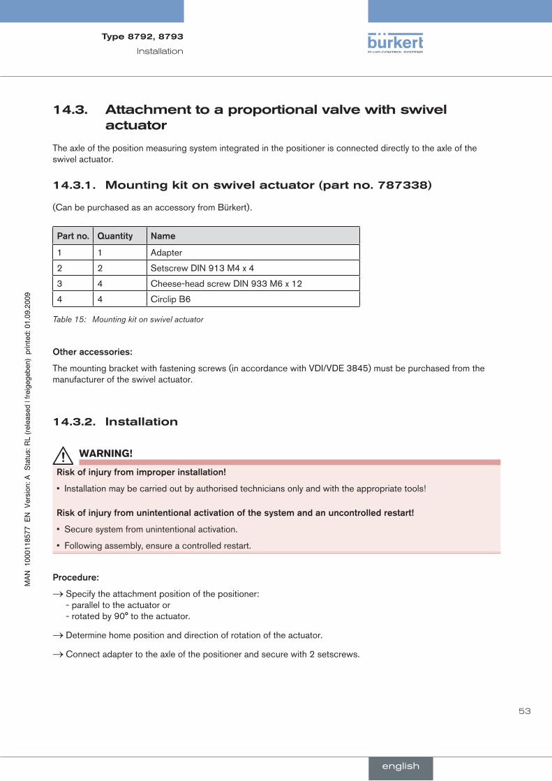
14.2.4. aligninglevermechanism
The lever mechanism cannot be correctly aligned until the device has been connected electrically and pneumatically.
Move the actuator in manual mode to half stroke (according to the scale on the actuator). →
Adjust the height of the positioner until the lever is horizontal. →
Fix the positioner in this position on the actuator. →
53
Installation
Type8792,8793
english
14.3. attachmenttoaproportionalvalvewithswivelactuator
The axle of the position measuring system integrated in the positioner is connected directly to the axle of the swivel actuator.
Mountingkitonswivelactuator(partno.787338)14.3.1.
(Can be purchased as an accessory from Bürkert).
Part.no. Quantity name
1 1 Adapter
2 2 Setscrew DIN 913 M4 x 4
3 4 Cheese-head screw DIN 933 M6 x 12
4 4 Circlip B6
Table 15: Mounting kit on swivel actuator
Other.accessories:
The mounting bracket with fastening screws (in accordance with VDI/VDE 3845) must be purchased from the manufacturer of the swivel actuator.
installation14.3.2.
WarnInG!
risk.of.injury.from.improper.installation!
Installation may be carried out by authorised technicians only and with the appropriate tools!•
risk.of.injury.from.unintentional.activation.of.the.system.and.an.uncontrolled.restart!
Secure system from unintentional activation.•
Following assembly, ensure a controlled restart.•
Procedure:
Specify the attachment position of the positioner: →- parallel to the actuator or - rotated by 90° to the actuator.
Determine home position and direction of rotation of the actuator. →
Connect adapter to the axle of the positioner and secure with 2 setscrews. →
54
Installation
Type8792,8793
english
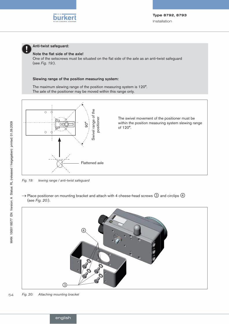
Anti-twist.safeguard:
note.the.flat.side.of.the.axle!..One of the setscrews must be situated on the flat side of the axle as an anti-twist safeguard (see Fig. 19:).
Slewing.range.of.the.position.measuring.system:
The maximum slewing range of the position measuring system is 120°. The axle of the positioner may be moved within this range only.
90°
Sw
ivel
rang
e of
the
posi
tione
r The swivel movement of the positioner must be within the position measuring system slewing range of 120°.
Flattened axle
Fig. 19: lewing range / anti-twist safeguard
Place positioner on mounting bracket and attach with 4 cheese-head screws → ③ and circlips ④ (see Fig. 20:).
③
④
Fig. 20: Attaching mounting bracket
55
Installation
Type8792,8793
english
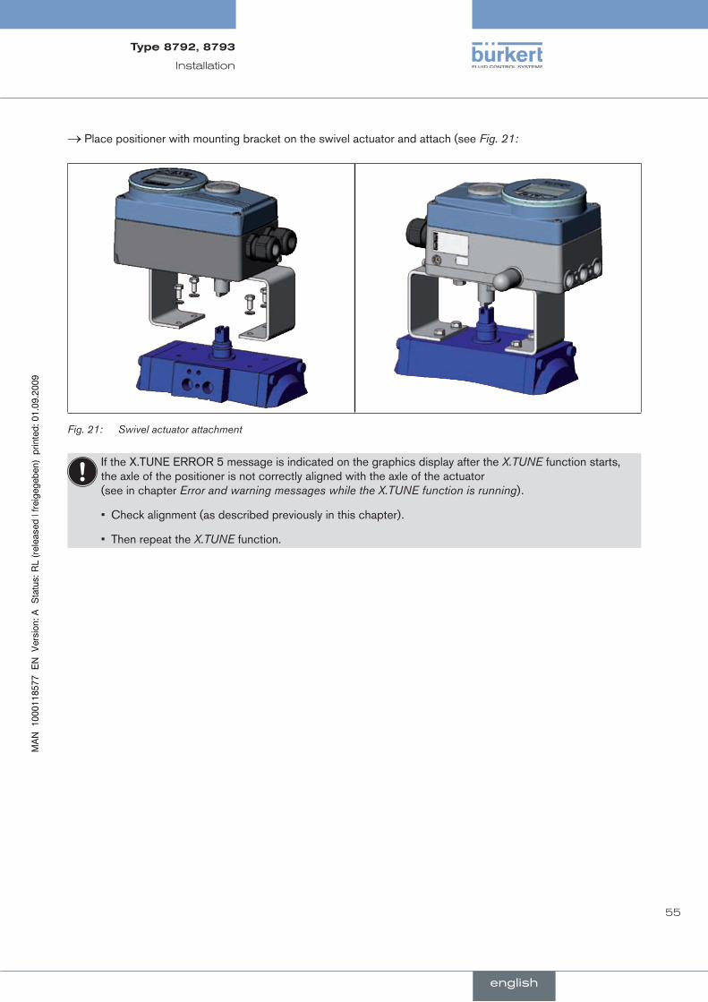
Place positioner with mounting bracket on the swivel actuator and attach (see → Fig. 21:
Fig. 21: Swivel actuator attachment
If the X.TUNE ERROR 5 message is indicated on the graphics display after the X.TUNE function starts, the axle of the positioner is not correctly aligned with the axle of the actuator (see in chapter Error and warning messages while the X.TUNE function is running).
Check alignment (as described previously in this chapter).•
Then repeat the • X.TUNE function.

56
Installation
Type8792,8793
english
remoteoperationwithexternalposition14.4.measuringsystem
In the case of this model the positioner has no position measuring system in the form of a rotary position sensor, but an external remote sensor.
Either the remote sensor type 8798 can be connected via a serial, digital interface or any high-resolution path sensor can be connected via a 4 – 20 mA interface.
Mountingaccessories14.4.1.
There are two options of attaching the positioner in remote operation (see Fig. 22:).
Installation on a DIN rail with accessory kit, part no. 675702
Installation on a wall with accessory kit, part no. 675715
Fig. 22: Attachment types in remote operation

57
Installation
Type8792,8793
english
connectionandstart-upoftheremotesensorType879814.4.2.
WarnInG!
risk.of.injury.from.improper.start-up!
Start-up may be carried out by authorised technicians only and with the appropriate tools!•
risk.of.injury.from.unintentional.activation.of.the.system.and.an.uncontrolled.restart!
Secure system from unintentional activation.•
Following assembly, ensure a controlled restart.•
Connect the 4 wires of the sensor cable to the designated screw-type terminals of the positioner →(see chapter 17.2.4.Connecting the external position measuring system (for remote model only)).
Attach remote sensor on the actuator. →The correct procedure is described in the brief instructions for the remote sensor.
Connect compressed air to positioner. →
Connect positioner pneumatically to the actuator. →
Switch on power supply to the positioner. →
Run the → X.TUNE function.
58
Installation
Type8792,8793
english
connectionandstart-upviaa4–20mapathsensor(for14.4.3.type8793remotemodelonly)
When a 4 – 20 mA path sensor is connected, the process controller type 8793 can be used as a position controller only, as the process actual value input is used as input for the path sensor.
In principle, any path sensor with a 4 – 20 mA output can be connected which has an adequate resolution of the path signal.
Good control properties are obtained if the resolution of the path sensor allows at least 1000 measuring steps over the path to be measured.
Example: Path sensor with 150 mm measurement range Of which used measurement range (= stroke) 100 mm
Required minimum resolution of the sensor:
100 mm= 0.1 mm
1000 Steps
WarnInG!
risk.of.injury.from.improper.start-up!
Start-up may be carried out by authorised technicians only and with the appropriate tools!•
risk.of.injury.from.unintentional.activation.of.the.system.and.an.uncontrolled.restart!
Secure system from unintentional activation.•
Following assembly, ensure a controlled restart.•
Connect 4 – 20 mA path sensor to the terminals 1 - 4 of the process controller type 8793 remote model. (see chapter 17.3.1., Table 25:Terminal assignments of the process actual value input / row 1 or 3).
Attach path sensor to the drive. →The correct procedure is described in the instructions for the path sensor.
Connect compressed air to the process controller type 8793. →
Connect process controller type 8793 pneumatically to the drive →
Switch on positioner power supply. →
To obtain the best possible control precision, adjust the path sensor so that path to be measured corresponds →to the signal range 4 – 20 mA (only if the path sensor includes this function).
In the menu activate the → POS.SENSOR function via ADDFUNCTION and set to ANALOG. (see chapter POS.SENSOR).
Run the → X.TUNE function.
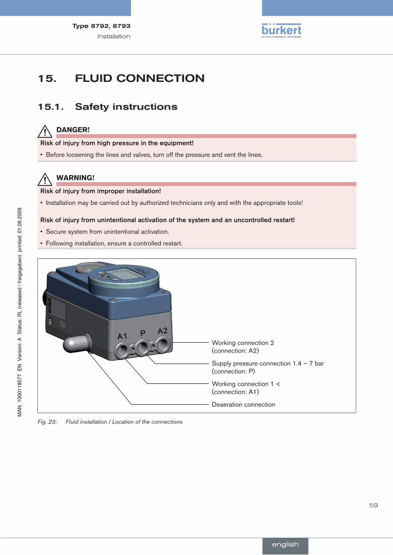
59
Installation
Type8792,8793
english
fluidcOnnecTiOn15.
safetyinstructions15.1.
danGer!
risk.of.injury.from.high.pressure.in.the.equipment!
Before loosening the lines and valves, turn off the pressure and vent the lines.•
WarnInG!
risk.of.injury.from.improper.installation!
Installation may be carried out by authorized technicians only and with the appropriate tools!•
risk.of.injury.from.unintentional.activation.of.the.system.and.an.uncontrolled.restart!
Secure system from unintentional activation.•
Following installation, ensure a controlled restart.•
Working connection 2 (connection: A2)
Supply pressure connection 1.4 – 7 bar (connection: P)
Working connection 1 < (connection: A1)
Deaeration connection
Fluid installation / Location of the connectionsFig. 23:

60
Installation
Type8792,8793
english
Procedure:
Apply supply pressure (1.4 – 7 bar) to the supply pressure connection P. →
For.single-acting.actuators:
Connect one working connection (A1 or A2, depending on required safety position) to the chamber of the →single-acting actuator. Safety positions see chapter 10.1.Safety positions after failure of the electrical or pneumatic auxiliary power).
Seal a working connection which is not required with a plug. →
For.double-acting.actuators:
Connect working connections A1 and A2 to the respective chambers of the double-acting actuator. →
Important.information.for.perfect.control.behaviour!
This ensures that the control behaviour is not extremely negatively affected in the upper stroke range on account of too little pressure difference.
keep the applied supply pressure at least 0.5 – 1 bar above the pressure which is required to move the • pneumatic actuator to its end position.
If fluctuations are greater, the control parameters measured with the X.TUNE function are not optimum.
during operation keep the fluctuations of the supply pressure as low as possible (max. ±10%).•

61
Installation
Type8792,8793
english
elecTricalcOnnecTiOn-16.MulTi-pOleplugversiOn
danGer!
risk.of.injury.due.to.electrical.shock!
Before reaching into the device or the equipment, switch off the power supply and secure to prevent • reactivation!
Observe applicable accident prevention and safety regulations for electrical equipment!•
WarnInG!
risk.of.injury.from.improper.installation!
Installation may be carried out by authorized technicians only and with the appropriate tools!•
risk.of.injury.from.unintentional.activation.of.the.system.and.an.uncontrolled.restart!
Secure system from unintentional activation.•
Following installation, ensure a controlled restart.•
using.the.4.–.20.mA.nominal.value.input
If the operating voltage of one positioner device fails in a series connection of several devices, the input of the failed positioner device becomes highly resistive. As a result, the 4 – 20 mA standard signal fails. In this case please contact Bürkert Service directly. If.PrOFIBuS.DP.or.Devicenet: The designation of the multipole plugs and sockets and the contacts can be found in the respective chapters.
Type8792-designationofthecircularconnectors16.1.
M8, 4-pole socketM12, 8-pole plug Function earth FE
Operating voltage and diverse signals
Binary outputs optional
42
1 3
12
3
4
5
6
7
8
Type 8792; designation of the circular connectors and contactsFig. 24:

62
Installation
Type8792,8793
english
16.2. connectionofthepositioncontrollerType8792
inputsignalsofthecontrolcentre(e.g.plc)-16.2.1.M12,8-poleplug
Pin Wire.colour* Configuration External.circuit./.Signal.level
1 white Set-point value + (0/4 – 20 mA or 0 – 5/10 V
1 + (0/4 – 20 mA or 0 – 5 / 10 V) completely galvanically isolated
2 brown Set-point value GND 2 GND
5 grey Binary input 5 + 0 – 5 V (log. 0)
10 – 30 V (log. 1)
6 pink Binary input GND 6 GND
* The indicated wire colours refer to the connection cable, part no. 919061, available as an accessory.
Pin assignment; input signals of the control centre - M12, 8-pole plugTable 16:
Outputsignalstothecontrolcentre(e.g.plc)-16.2.2.M12,8-poleplug(requiredforanalogueoutputoptiononly)
Connect pins according to the model (options) of the positioner. →
Pin Wire.colour* Configuration External.circuit./.signal.level
8 red Analogue feedback + 8 + (0/4 – 20 mA or 0 – 5 / 10 V) completely galvanically isolated
7 blue Analogue feedback GND 7 GND
* The indicated wire colours refer to the connection cable, part no. 919061, available as an accessory.
Pin assignment; output signals to the control centre - M12, 8-pole plugTable 17:
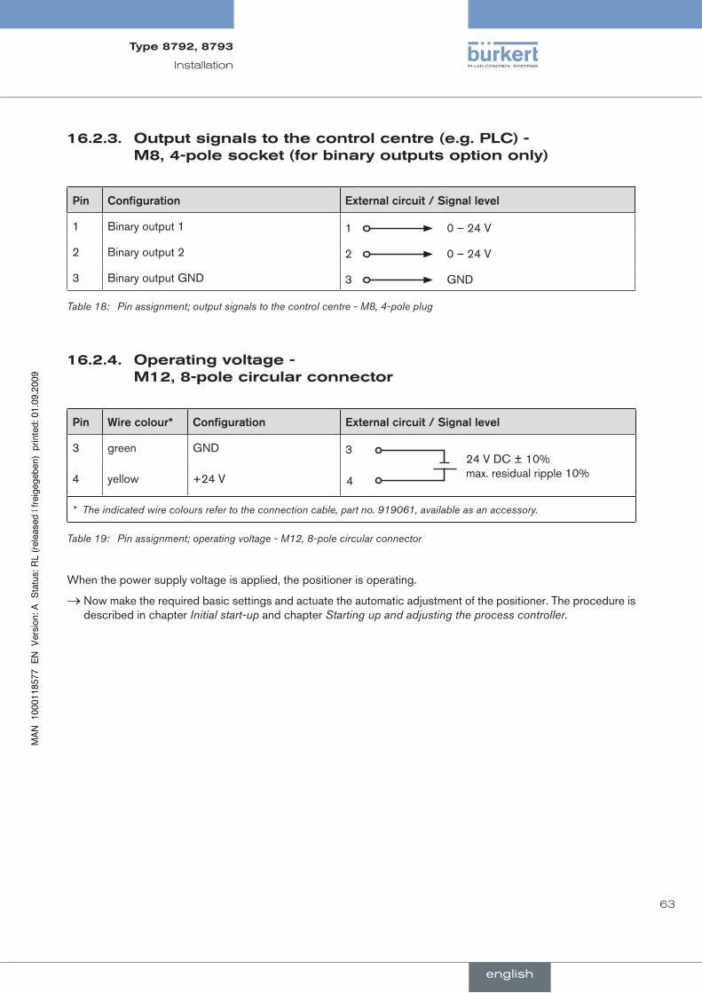
63
Installation
Type8792,8793
english
Outputsignalstothecontrolcentre(e.g.plc)-16.2.3.M8,4-polesocket(forbinaryoutputsoptiononly)
Pin Configuration External.circuit./.Signal.level
1 Binary output 1 1 0 – 24 V
2 Binary output 2 2 0 – 24 V
3 Binary output GND 3 GND
Pin assignment; output signals to the control centre - M8, 4-pole plugTable 18:
Operatingvoltage-16.2.4.M12,8-polecircularconnector
Pin Wire.colour* Configuration External.circuit./.Signal.level
3 green GND 3
4
24 V DC ± 10% max. residual ripple 10%4 yellow +24 V
* The indicated wire colours refer to the connection cable, part no. 919061, available as an accessory.
Pin assignment; operating voltage - M12, 8-pole circular connectorTable 19:
When the power supply voltage is applied, the positioner is operating.
Now make the required basic settings and actuate the automatic adjustment of the positioner. The procedure is →described in chapter Initial start-up and chapter Starting up and adjusting the process controller.

64
Installation
Type8792,8793
english
Type8793-designationofthecircularconnectors16.3.andcontacts
Function earth FE
M12, 8-pole plug
Operating voltage and diverse signals
M8, 4-pole plug
Binary outputs
M8, 4-pole socket
Process actual value
24
3 1
42
1 3
12
3
4
5
6
7
8
Type 8793; designation of the multi-pole connectors and contactsFig. 25:
location.of.the.DIP.switch:
Symbols for switch position
Location of the DIP switch
Switch on left
Switch on right
Location of the DIP switch; symbols for switch positionFig. 26:
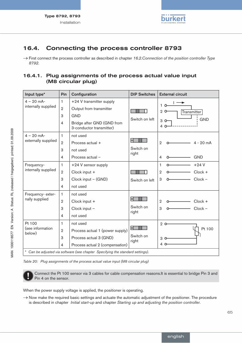
65
Installation
Type8792,8793
english
connectingtheprocesscontroller879316.4.
First connect the process controller as described in chapter → 16.2.Connection of the position controller Type 8792.
plugassignmentsoftheprocessactualvalueinput16.4.1.(M8circularplug)
Input.type* Pin Configuration DIP.Switches External.circuit
4 – 20 mA- internally supplied
1 +24 V transmitter supply
Switch on left
1
2
34
Transmitter
GND
I2 Output from transmitter
3 GND
4 Bridge after GND (GND from 3-conductor transmitter)
4 – 20 mA- externally supplied
1 not used
Switch on right
2 Process actual + 2 4 - 20 mA
3 not used
4 Process actual – 4 GND
Frequency- internally supplied
1 +24 V sensor supply
Switch on left
1 +24 V
2 Clock input + 2 Clock +
3 Clock input – (GND) 3 Clock –
4 not used
Frequency- exter-nally supplied
1 not used
Switch on right
2 Clock input + 2 Clock +
3 Clock input – 3 Clock –
4 not used
Pt 100 (see information below)
1 not used
Switch on right
2
34
Pt 1002 Process actual 1 (power supply)
3 Process actual 3 (GND)
4 Process actual 2 (compensation)
* Can be adjusted via software (see chapter Specifying the standard settings).
Plug assignments of the process actual value input (M8 circular plug)Table 20:
Connect the Pt 100 sensor via 3 cables for cable compensation reasons.It is essential to bridge Pin 3 and Pin 4 on the sensor.
When the power supply voltage is applied, the positioner is operating.
Now make the required basic settings and actuate the automatic adjustment of the positioner. The procedure →is described in chapter Initial start-up and chapter Starting up and adjusting the position controller.
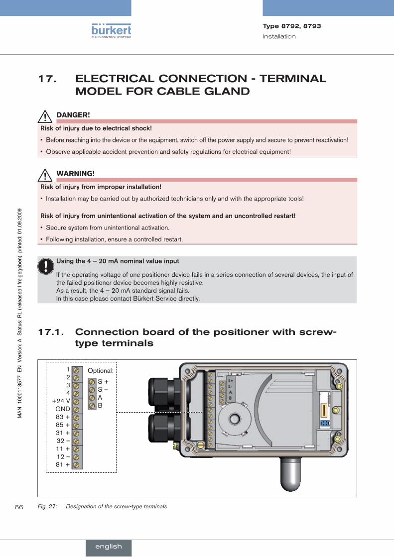
66
Installation
Type8792,8793
english
elecTricalcOnnecTiOn-TerMinal17.MOdelfOrcaBlegland
danGer!
risk.of.injury.due.to.electrical.shock!
Before reaching into the device or the equipment, switch off the power supply and secure to prevent reactivation!•
Observe applicable accident prevention and safety regulations for electrical equipment!•
WarnInG!
risk.of.injury.from.improper.installation!
Installation may be carried out by authorized technicians only and with the appropriate tools!•
risk.of.injury.from.unintentional.activation.of.the.system.and.an.uncontrolled.restart!
Secure system from unintentional activation.•
Following installation, ensure a controlled restart.•
using.the.4.–.20.mA.nominal.value.input
If the operating voltage of one positioner device fails in a series connection of several devices, the input of the failed positioner device becomes highly resistive. As a result, the 4 – 20 mA standard signal fails. In this case please contact Bürkert Service directly.
connectionboardofthepositionerwithscrew-17.1.typeterminals
1 2 3 4
+24 V GND 83 + 85 + 31 + 32 – 11 + 12 – 81 +
S + S – A B
Optional:
Designation of the screw-type terminalsFig. 27:
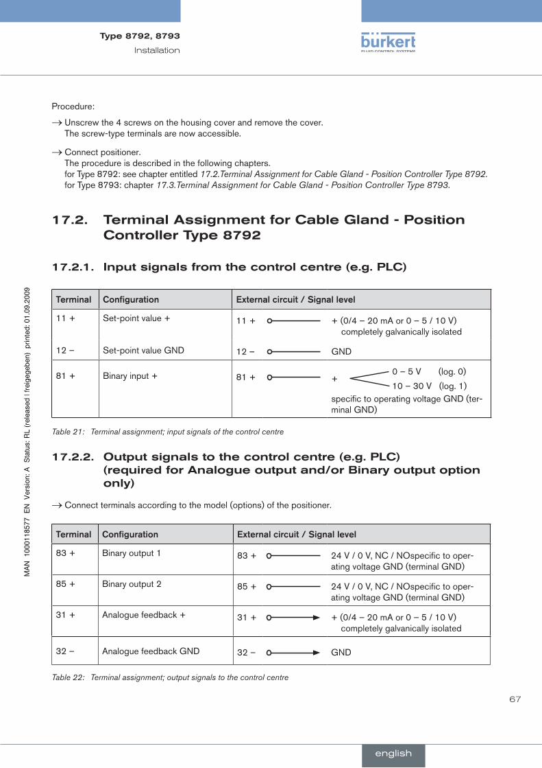
67
Installation
Type8792,8793
english
Procedure:
Unscrew the 4 screws on the housing cover and remove the cover. →The screw-type terminals are now accessible.
Connect positioner. →The procedure is described in the following chapters. for Type 8792: see chapter entitled 17.2.Terminal Assignment for Cable Gland - Position Controller Type 8792. for Type 8793: chapter 17.3.Terminal Assignment for Cable Gland - Position Controller Type 8793.
17.2. Terminalassignmentforcablegland-positioncontrollerType8792
inputsignalsfromthecontrolcentre(e.g.plc)17.2.1.
Terminal Configuration External.circuit./.Signal.level
11 + Set-point value + 11 + + (0/4 – 20 mA or 0 – 5 / 10 V) completely galvanically isolated
12 – Set-point value GND 12 – GND
81 +
Binary input +
81 +
+ 0 – 5 V (log. 0)
10 – 30 V (log. 1) specific to operating voltage GND (ter-minal GND)
Terminal assignment; input signals of the control centre Table 21:
Outputsignalstothecontrolcentre(e.g.plc)17.2.2.(requiredforanalogueoutputand/orBinaryoutputoptiononly)
Connect terminals according to the model (options) of the positioner. →
Terminal Configuration External.circuit./.Signal.level
83 + Binary output 1 83 + 24 V / 0 V, NC / NOspecific to oper-ating voltage GND (terminal GND)
85 + Binary output 2 85 + 24 V / 0 V, NC / NOspecific to oper-ating voltage GND (terminal GND)
31 + Analogue feedback + 31 + + (0/4 – 20 mA or 0 – 5 / 10 V) completely galvanically isolated
32 – Analogue feedback GND 32 – GND
Terminal assignment; output signals to the control centre Table 22:

68
Installation
Type8792,8793
english
Operatingvoltage17.2.3.
Terminal Configuration External.circuit./.Signal.level
+24 V Operating voltage + +24 V
GND
24 V DC ± 10% max. residual ripple 10%GND Operating voltage GND
Pin assignment; operating voltage - M12, 8-pole circular connectorTable 23:
17.2.4. connectingtheexternalpositionmeasuringsystem(forremotemodelonly)
Terminal Configuration External.circuit./.Signal.level
S + Supply sensor + S + +Remote
Sensor
Typ 8798
S - Supply sensor – S – –
A Serial interface, A cable A A line
B Serial interface, B-cable B B line
Terminal assignment; external position measuring systemTable 24:
When the power supply voltage is applied, the positioner is operating.
Now make the required basic settings and actuate the automatic adjustment of the positioner. The procedure is →described in chapter Initial start-up and chapter Starting up and adjusting the position controller.
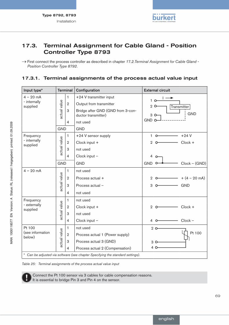
69
Installation
Type8792,8793
english
17.3. Terminalassignmentforcablegland-positioncontrollerType8793
First connect the process controller as described in chapter → 17.2.Terminal Assignment for Cable Gland - Position Controller Type 8792.
17.3.1. Terminalassignmentsoftheprocessactualvalueinput
Input.type* Terminal Configuration External.circuit
4 – 20 mA - internally supplied
actu
al v
alue
1 +24 V transmitter input1
2
3GND
Transmitter
GND
I
2 Output from transmitter
3 Bridge after GND (GND from 3-con-ductor transmitter)
4 not used
GND GND
Frequency - internally supplied
actu
al v
alue
1 +24 V sensor supply 1 +24 V
2 Clock input + 2 Clock +
3 not used
4 Clock input – 4
GND GND GND Clock – (GND)
4 – 20 mA
actu
al v
alue
1 not used
2 Process actual + 2 + (4 – 20 mA)
3 Process actual – 3 GND
4 not used
Frequency - externally supplied
actu
al v
alue
1 not used
2 Clock input + 2 Clock +
3 not used
4 Clock input – 4 Clock –
Pt 100 (see information below)
actu
al v
alue
1 not used 2
34
Pt 1002 Process actual 1 (Power supply)
3 Process actual 3 (GND)
4 Process actual 2 (Compensation)
* Can be adjusted via software (see chapter Specifying the standard settings).
Table 25: Terminal assignments of the process actual value input
Connect the Pt 100 sensor via 3 cables for cable compensation reasons. It is essential to bridge Pin 3 and Pin 4 on the sensor.
70
Installation
Type8792,8793
english
When the power supply voltage is applied, the positioner is operating.
Now make the required basic settings and actuate the automatic adjustment of the positioner. The procedure →is described in chapter Initial start-up and chapter Starting up and adjusting the position controller.

71
Type8792,8793
english
conTenTs
18.. InITIAl.STArT-uP.............................................................................................................................................................................72
18.1.. Safety.instructions..............................................................................................................................................................72
18.2.. Installation...............................................................................................................................................................................72
18.3.. Specifying.the.standard.settings.................................................................................................................................72
18.3.1. Setting the Input Signal (Standard Signal) .......................................................................................73
18.3.2. Running the Automatic Adjustment X.TUNE ..................................................................................74
18.3.3. Overview of the operating structure for initial start-up ...................................................................75
Initial start-up
english
Type8792,8793
72
Initial start-up
Type8792,8793
english
18. iniTialsTarT-up
This section enables you to start up the positioner quickly in order to perform a function check. Additional functions which are not required are not dealt with in this chapter.
safetyinstructions18.1.
danGer!
risk.of.injury.from.high.pressure.in.the.equipment!
Before loosening the lines and valves, turn off the pressure and vent the lines.•
WarnInG!
risk.of.injury.from.improper.start-up!
Start-up may be carried out by authorised technicians only and with the appropriate tools!•
risk.of.injury.from.unintentional.activation.of.the.system.and.an.uncontrolled.restart!
Secure system from unintentional activation.•
Following start-up, ensure a controlled restart.•
installation18.2.
Before start-up, carry out fluid and electrical installation of the positioner and valve. →
When the operating voltage is applied, the positioner is operating and is in the AUTOMATIC operating state.
18.3. specifyingthestandardsettings
The basic settings of the positioner are implemented at the factory.
Before the positioner can undergo a function check, the unit input signal (standard signal) must still be set following installation of the device and the X.TUNE function run to adjust the device to local conditions.
To specify the basic settings, switch from the process operating level to the configuration level.
Hold down the left selection key (MENU) for approx. 3 seconds (countdown: two bars converge on the display). Then the main menu (MAIN) is indicated on the display together with the menu options which can be individually marked via the arrow keys and then selected via the right selection key (ENTER). (see Fig. 28:Operating module; Specifying the Basic Settings).
english
Type8792,8793
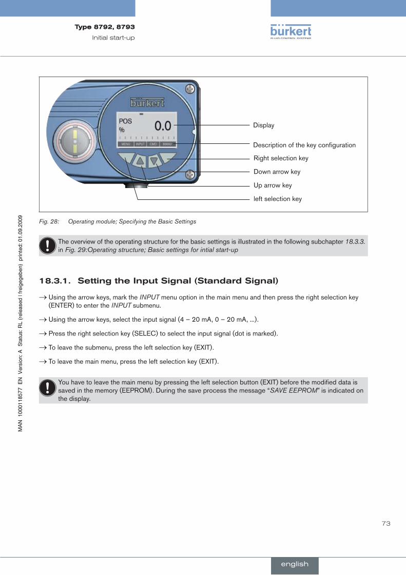
73
Initial start-up
Type8792,8793
english
Display
Description of the key configuration
Right selection key
Down arrow key
Up arrow key
left selection key
Fig. 28: Operating module; Specifying the Basic Settings
The overview of the operating structure for the basic settings is illustrated in the following subchapter 18.3.3. in Fig. 29:Operating structure; Basic settings for intial start-up
settingtheinputsignal(standardsignal)18.3.1.
Using the arrow keys, mark the → INPUT menu option in the main menu and then press the right selection key (ENTER) to enter the INPUT submenu.
Using the arrow keys, select the input signal (4 – 20 mA, 0 – 20 mA, ...). →
Press the right selection key (SELEC) to select the input signal (dot is marked). →
To leave the submenu, press the left selection key (EXIT). →
To leave the main menu, press the left selection key (EXIT). →
You have to leave the main menu by pressing the left selection button (EXIT) before the modified data is saved in the memory (EEPROM). During the save process the message “SAVE EEPROM” is indicated on the display.
english
Type8792,8793
74
Initial start-up
Type8792,8793
english
runningtheautomaticadjustment18.3.2. X.TUNE
An exact description of the X.TUNE function can be found in the chapter entitled Start-up and operation of the position controller Type 8792.
WarnInG!
uncontrolled.valve.movements.while.the.X:TUNE.function.is.running!
While this function is running, the valve automatically moves from its current position!
Never run • X.TUNE while a process is running!
Take appropriate measures to prevent the equipment from being unintentionally actuated!•
note!
An.incorrect.supply.pressure.or.incorrectly.connected.operating.medium.pressure.may.cause.the.con-troller.to.be.wrongly.adjusted!
X.TUNE• at the supply pressure available during subsequent operation (= pneumatic auxiliary energy).
Run the • X.TUNE function preferably without operating medium pressure to exclude interference caused by flow forces.
To enter the main menu, hold down the left selection key (MENU) for approx. 3 s (countdown on the display). →
Using the arrow keys, select the → X.TUNE menu option.
To start the automatic adjustment → X.TUNE, hold down the right selection key (RUN) for approx. 3 s (countdown on the display).
While the automatic adjustment is running, messages on the progress of the X.TUNE (e.g. “TUNE #1....”) are indi-cated on the display.
When the automatic adjustment completes, the message “X.TUNE READY” is indicated.
To return to the main menu, press any key. →
To leave the main menu, press the left selection key (EXIT). →
You have to leave the main menu by pressing the left selection button (EXIT) before the modified data is saved in the memory (EEPROM). During the save process the message “SAVE EEPROM” is indicated on the display.
english
Type8792,8793
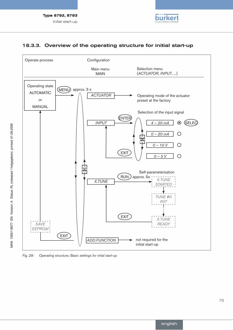
75
Initial start-up
Type8792,8793
english
18.3.3. Overviewoftheoperatingstructureforinitialstart-up
Operating state
AUTOMATIC
or
MANUAL
MENUACTUATOR
INPUT
X.TUNE
ADD.FUNCTION
SAVE EEPROM
SELEC4 – 20 mA
EXIT
ENTER
approx. 3 s
RUN approx. 5sX.TUNE
STARTED
TUNE #0 INIT
X.TUNE READY
EXIT
0 – 20 mA
0 – 10 V
0 – 5 V
EXIT
Main menu MAIN
Selection menu (ACTUATOR, INPUT, ...)
Operate process Configuration
Operating mode of the actuator preset at the factory
not required for the initial start-up
Selection of the input signal
Self-parameterization
Fig. 29: Operating structure; Basic settings for intial start-up
english
Type8792,8793

76
Initial start-up
english
Type8792,8793
english

77
conTenTs
19.. STArTInG.uP.AnD.ADjuSTInG.ThE.POSITIOn.COnTrOllEr...............................................................................79
19.1.. Safety.instructions..............................................................................................................................................................79
19.2.. Installation...............................................................................................................................................................................79
19.3.. Procedure.for.specifying.the.settings......................................................................................................................79
19.4.. Factory.settings.of.the.position.controller.............................................................................................................80
19.5.. Specifying.the.standard.settings.................................................................................................................................81
19.6.. Description.of.the.basic.functions.in.the.main.menu......................................................................................82
19.6.1. Main menu of the positioner ...............................................................................................................82
19.6.2. Inputting the input signal .....................................................................................................................83
19.6.3. Automatic adjustment (autotune) of the position controller ........................................................83
19.6.4. Adding auxiliary functions ...................................................................................................................84
19.6.5. Leaving the main menu ........................................................................................................................84
20.. OPErATInG.ThE.POSITIOn.COnTrOllEr..........................................................................................................................85
20.1.. Switching.between.the.operating.states................................................................................................................85
20.2.. Switching.between.the.operating.levels.................................................................................................................86
20.3.. AuTOMATIC.operating.state..........................................................................................................................................86
20.3.1. Meaning of the keys .............................................................................................................................86
20.3.2. Information on the display ...................................................................................................................87
20.3.3. Operating structure ..............................................................................................................................87
20.4.. MAnuAl.operating.state.................................................................................................................................................88
20.4.1. Meaning of the keys .............................................................................................................................88
20.4.2. Information on the display ...................................................................................................................89
20.4.3. Operating structure ..............................................................................................................................89
21.. COnFIGurInG.ThE.AuxIlIArY.FunCTIOnS......................................................................................................................90
21.1.. Keys.at.the.Configuration.level....................................................................................................................................90
21.2.. Configuration.menu............................................................................................................................................................91
21.2.1. Switching between process operating level and configuration level ........................................91
21.2.2. Including auxiliary functions in the main menu ...............................................................................91
Start-up and operation of the position controller type 8792
english
Type8792,8793

78
Start-up, operation
position controller Type 8792
21.2.3. Removing auxiliary functions from the main menu .........................................................................92
21.2.4. Setting numerical values .....................................................................................................................92
21.2.5. Principle of including auxiliary functions in the main menu .........................................................93
21.3.. Auxiliary.functions...............................................................................................................................................................94
21.3.1. Overview of auxiliary functions for the position controller Type 8792 ......................................94
21.3.2. CHARACTSelect the transfer characteristic between input signal (position set-point value) and stroke ...................................................................................................................................95
21.3.3. Inputting the freely programmable characteristic ..........................................................................96
21.3.4. CUTOFFSealing function for the position controller type Type 8792 .................................99
21.3.5. DIR.CMDEffective sense (direction) of the position controller set-point value ............ 100
21.3.6. DIR.ACTEffective sense (direction) of the actuator driv ...................................................... 101
21.3.7. SPLTRNGSignal split range ....................................................................................................... 102
21.3.8. X.LIMITLimits the mechanical stroke range ........................................................................... 104
21.3.9. X.LIMITLimiting the control speed ........................................................................................... 105
21.3.10.X.CONTROLParameterization of the position controller ..................................................... 106
21.3.11.SECURITYCode protection for the settings .......................................................................... 107
21.3.12.SAFEPOSInput the safety position .......................................................................................... 108
21.3.13.SIG-ERRORConfiguration of signal level fault detection .................................................... 109
21.3.14.BINARY-INActivation of the binary input ................................................................................. 110
21.3.15.OUTPUT (option)Configuring the outputs .............................................................................. 111
21.3.16.CAL.USERCalibrating the actual value display and the inputs for the position set-point value ...................................................................................................................................................... 116
21.3.17.SET.FACTORYResetting to the factory settings ................................................................... 118
21.3.18.SER.I\OSettings of the serial interface .................................................................................. 119
21.3.19.EXTRAS .....................................................................................................120
21.3.20.POS.SENSOR ..........................................................................................120
21.3.21.SERVICE ...................................................................................................120
english
Type8792,8793Type8792,8793

79
Start-up, operation
position controller Type 8792
19. sTarTingupandadjusTingThepOsiTiOncOnTrOller
safetyinstructions19.1.
danGer!
risk.of.injury.from.high.pressure.in.the.equipment!
Before loosening the lines and valves, turn off the pressure and vent the lines.•
WarnInG!
risk.of.injury.from.improper.start-up!
Start-up may be carried out by authorised technicians only and with the appropriate tools!•
risk.of.injury.from.unintentional.activation.of.the.system.and.an.uncontrolled.restart!
Secure system from unintentional activation.•
Following start-up, ensure a controlled restart.•
installation19.2.
Before start-up, carry out fluid and electrical installation of the positioner and valve. →
procedureforspecifyingthesettings19.3.
When the operating voltage has been switched on, the positioner is at the process operating level in the AUTOMATIC operating state.
To specify the standard settings, switch to the configuration level.
Hold down the left selection key (MENU) for approx. 3 seconds (wait for countdown on display). →
Then the main menu is indicated on the display (MAIN).
Use the arrow keys to switch between the main menu options and select a menu. →
Press the right selection key (ENTER/RUN) to confirm the selection. →
Depending on the function, a menu sub-option or a selection screen is indicated on the display.
Use the arrow keys to switch between the submenu options and select the required settings.
Press the right selection key (SELEC/ENTER) to confirm the selection (the dot after the selected parameter is →now marked).
To return to the main menu, press the left selection key (EXIT). →
english
Type8792,8793Type8792,8793

80
Start-up, operation
position controller Type 8792
To save the changed settings, leave the configuration level by pressing the left selection key (EXIT). →
The positioner is now back on the process operating level.
Only when you leave the configuration level by pressing the right selection key, are the changed param-eters and settings saved (“save EEPROM”).
19.4. factorysettingsofthepositioncontroller
Function... . .Factory.setting Function... . . Factory.setting
INPUT 4 – 20 mA
CHARACT linear
DIR.CMD Rise
CUTOFF Min 0% Max 100%
DIR.ACT Rise
SPLTRNG Min 0% Max 100%
X.LIMIT Min 0% Max 100% X.TIME
Open (1s) Values of X.TUNE determined
Close (1s) Values of X.TUNE determined
After running SET.FACTORY: 1 s
BINARY. IN SafePos
BIN. IN type normally open
X.CONTROL
DBND . 1.0%
KXopn (1) Values of X.TUNE determined
KXcls (1) Values of X.TUNE determined
After running SET.FACTORY: 1
SECURITY
. Access Code 1 0000 SAFEPOS 0%
SIG.ERROR . SP/CMD Input Error off
OUTPUT*
OUT ANALOG Out POS
OUT type 4 – 20 mA
OUT BIN1 Out DEV.X
Lim. DEV.X 1.0%
OUT.BIN1 type normally open
OUT BIN2 Out DEV.X
. . . . . . . Lim. DEV.X 1.0%
OUT.BIN1 type normally open
* only optional
Factory settings of the position controller Table 26:
english
Type8792,8793Type8792,8793
81
Start-up, operation
position controller Type 8792
19.5. specifyingthestandardsettings
When starting up the positioner for the first time, implement the following standard settings:
Specify the selected unit signal input for the set-point value default ( → INPUT) (4 – 20 mA; 0 – 20 mA; 0 – 10 V or 0 – 5 V).
Start automatic adjustment of the position controller to the particular operating conditions ( → X.TUNE)
The exact description of the INPUT and X.TUNE functions can be found in the chapter entitled 19.6.Description of the basic functions in the main menu.
The basic settings for the positioner are implemented at the factory. During start-up, however, it is essential to input the unit signal (INPUT) and run X.TUNE. Using the X.TUNE function, the positioner automatically determines the optimum settings for the current operating conditions.
If the auxiliary function X.CONTROL is in the main menu while X.TUNE is running, the position controller dead band DBND is also determined automatically depending on the friction behaviour of the actuator drive (see chapter entitled 21.3.10.X.CONTROL Parameterization of the position controller).
english
Type8792,8793Type8792,8793

82
Start-up, operation
position controller Type 8792
19.6. descriptionofthebasicfunctionsinthemainmenu
Mainmenuofthepositioner19.6.1.
Operating state
AUTOMATIC
or
MANUAL
MENU
INPUT
X.TUNE
ADD.FUNCTION
SAVE EEPROM
SELEC4 – 20 mA
EXIT
ENTERapprox. 3 s
RUN
ENTER
approx. 3 s X.TUNE STARTED
TUNE #0 INIT
X.TUNE READY
EXIT
ENTERCHARACT
0 – 20 mA
0 – 10 V
0 – 5 V
CUTOFF
ENTERSERVICEEXIT
EXIT
Main menu MAIN
Selection menu (ACTUATOR, INPUT, ...)
Operate process Configuration
*
* ADD.FUNCTION is not required for the initial start-up
Operating structure; Basic settingsFig. 30:
english
Type8792,8793Type8792,8793
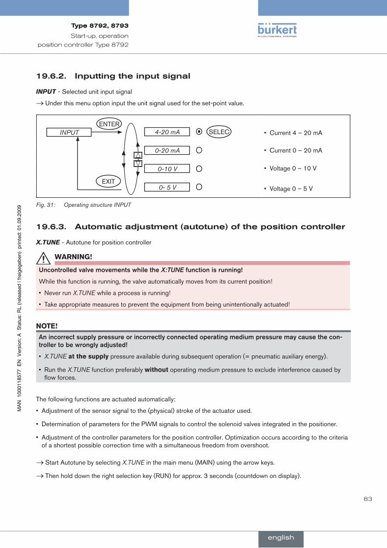
83
Start-up, operation
position controller Type 8792
inputtingtheinputsignal19.6.2.
INPUT- Selected unit input signal
Under this menu option input the unit signal used for the set-point value. →
INPUT SELEC4-20 mA
EXIT
ENTER
0-20 mA
0-10 V
0- 5 V
Current 4 – 20 mA•
Current 0 – 20 mA•
Voltage 0 – 10 V•
Voltage 0 – 5 V•
Operating structure INPUTFig. 31:
automaticadjustment(autotune)ofthepositioncontroller19.6.3.
X.TUNE - Autotune for position controller
WarnInG!
uncontrolled.valve.movements.while.the.X:TUNE.function.is.running!
While this function is running, the valve automatically moves from its current position!
Never run • X.TUNE while a process is running!
Take appropriate measures to prevent the equipment from being unintentionally actuated!•
note!
An.incorrect.supply.pressure.or.incorrectly.connected.operating.medium.pressure.may.cause.the.con-troller.to.be.wrongly.adjusted!
X.TUNE• at the supply pressure available during subsequent operation (= pneumatic auxiliary energy).
Run the • X.TUNE function preferably without operating medium pressure to exclude interference caused by flow forces.
The following functions are actuated automatically:
Adjustment of the sensor signal to the (physical) stroke of the actuator used.•
Determination of parameters for the PWM signals to control the solenoid valves integrated in the positioner.•
Adjustment of the controller parameters for the position controller. Optimization occurs according to the criteria • of a shortest possible correction time with a simultaneous freedom from overshoot.
Start Autotune by selecting → X.TUNE in the main menu (MAIN) using the arrow keys.
Then hold down the right selection key (RUN) for approx. 3 seconds (countdown on display). →
english
Type8792,8793Type8792,8793
84
Start-up, operation
position controller Type 8792
When the automatic adjustment completes, the message “X.TUNE READY” is indicated.
If an error occurs, the “TUNE err/break” message is indicated.
To return to the main menu, press any key. →
To stop X.TUNE, press the left or right selection key (STOP).
Sequence.for.automatic.adjustment.of.the.position.controller.to.the.particular.operating.conditions
Display Description
X.TUNE started
Start of X.TUNE
TUNE #0 Init
TUNE #1 Max-Pos
TUNE #2 Min-Pos
:
Display of the X.TUNE phase which is currently running (progress is indicated by a progress bar along the upper edge of the display).
X.TUNE ready
Display at the end of the X.TUNE
TUNE err/break
Display when a fault occurs
Automatic adjustment of the position controllerTable 27:
addingauxiliaryfunctions19.6.4.
ADD.FUNCTION
With ADD.FUNCTION auxiliary functions can be included in the main menu.
See chapter 21.Configuring the auxiliary functions.
Jump this menu option during the initial start-up.
leavingthemainmenu19.6.5.
To leave the main menu, press the left selection key (EXIT). →
You have to leave the main menu by pressing the left selection button (EXIT) before the modified data is saved in the memory (EEPROM). During the save process the message “SAVE EEPROM” is indicated on the display.
When the main menu is left, the device is back in the same operating state in which it was before the switchover to the main menu (MANUAL or AUTOMATIC).
english
Type8792,8793Type8792,8793
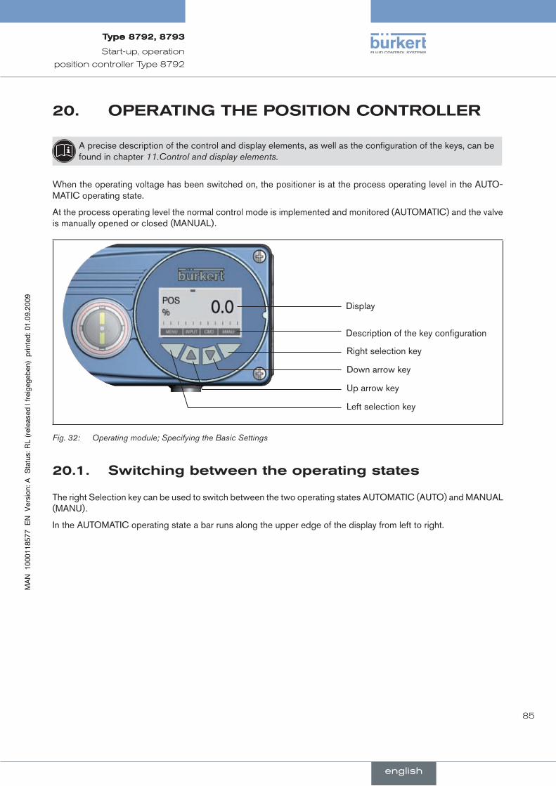
85
Start-up, operation
position controller Type 8792
OperaTingThepOsiTiOncOnTrOller20.
A precise description of the control and display elements, as well as the configuration of the keys, can be found in chapter 11.Control and display elements.
When the operating voltage has been switched on, the positioner is at the process operating level in the AUTO-MATIC operating state.
At the process operating level the normal control mode is implemented and monitored (AUTOMATIC) and the valve is manually opened or closed (MANUAL).
Display
Description of the key configuration
Right selection key
Down arrow key
Up arrow key
Left selection key
Operating module; Specifying the Basic SettingsFig. 32:
switchingbetweentheoperatingstates20.1.
The right Selection key can be used to switch between the two operating states AUTOMATIC (AUTO) and MANUAL (MANU).
In the AUTOMATIC operating state a bar runs along the upper edge of the display from left to right.
english
Type8792,8793Type8792,8793
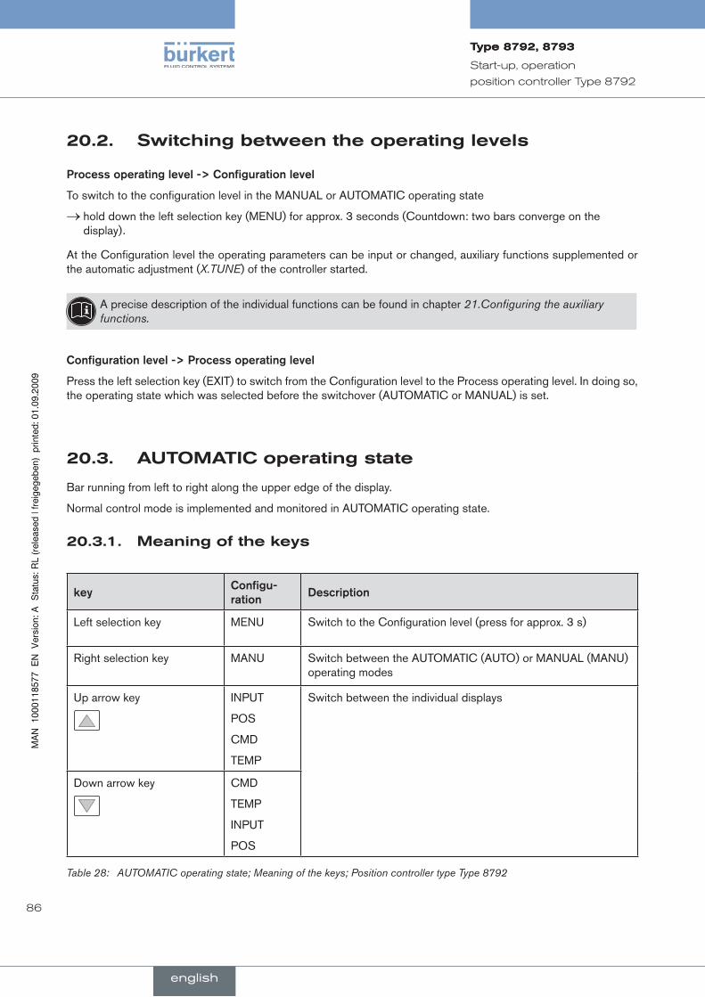
86
Start-up, operation
position controller Type 8792
switchingbetweentheoperatinglevels20.2.
Process.operating.level.->.Configuration.level
To switch to the configuration level in the MANUAL or AUTOMATIC operating state
hold down the left selection key (MENU) for approx. 3 seconds (Countdown: two bars converge on the →display).
At the Configuration level the operating parameters can be input or changed, auxiliary functions supplemented or the automatic adjustment (X.TUNE) of the controller started.
A precise description of the individual functions can be found in chapter 21.Configuring the auxiliary functions.
Configuration.level.->.Process.operating.level
Press the left selection key (EXIT) to switch from the Configuration level to the Process operating level. In doing so, the operating state which was selected before the switchover (AUTOMATIC or MANUAL) is set.
auTOMaTicoperatingstate20.3.
Bar running from left to right along the upper edge of the display.
Normal control mode is implemented and monitored in AUTOMATIC operating state.
Meaningofthekeys20.3.1.
keyConfigu-ration
Description
Left selection key MENU Switch to the Configuration level (press for approx. 3 s)
Right selection key MANU Switch between the AUTOMATIC (AUTO) or MANUAL (MANU) operating modes
Up arrow key INPUT
POS
CMD
TEMP
Switch between the individual displays
Down arrow key CMD
TEMP
INPUT
POS
AUTOMATIC operating state; Meaning of the keys; Position controller type Type 8792Table 28:
english
Type8792,8793Type8792,8793
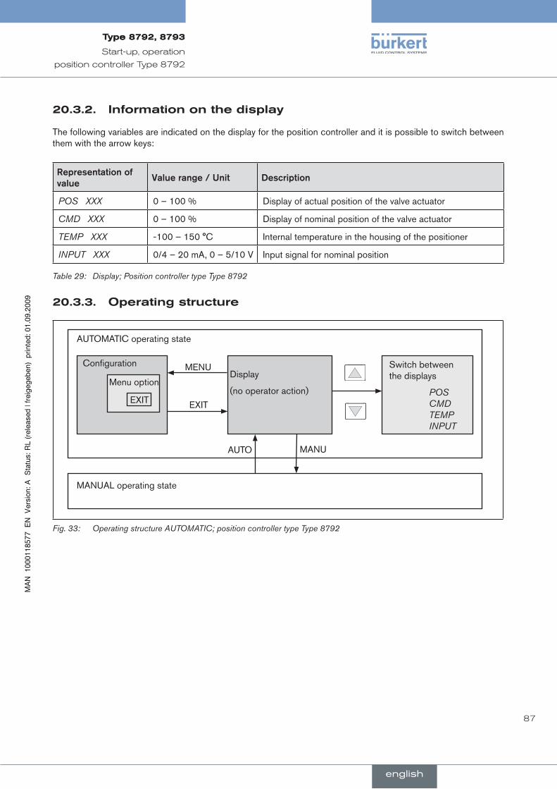
87
Start-up, operation
position controller Type 8792
informationonthedisplay20.3.2.
The following variables are indicated on the display for the position controller and it is possible to switch between them with the arrow keys:
representation.of.value
Value.range./.unit Description
POS XXX 0 – 100 % Display of actual position of the valve actuator
CMD XXX 0 – 100 % Display of nominal position of the valve actuator
TEMP XXX -100 – 150 °C Internal temperature in the housing of the positioner
INPUT XXX 0/4 – 20 mA, 0 – 5/10 V Input signal for nominal position
Display; Position controller type Type 8792Table 29:
Operatingstructure20.3.3.
Configuration
Menu option
EXIT
Display
(no operator action)
Switch between the displays
POS CMD TEMP INPUT
EXIT
MENU
AUTOMATIC operating state
MANUAL operating state
MANUAUTO
Operating structure AUTOMATIC; position controller type Type 8792Fig. 33:
english
Type8792,8793Type8792,8793

88
Start-up, operation
position controller Type 8792
Manualoperatingstate20.4.
Without bar running from left to right along the upper edge of the display.
In MANUAL operating state the valve can be opened or closed manually.
Meaningofthekeys20.4.1.
keyConfigu-ration
Description
Left selection key MENU Switch to the Configuration level (press for approx. 3 s)
Right selection key MANU Switch between the AUTOMATIC (AUTO) or MANUAL (MANU) operating modes
Up arrow key OPN
CLS*
Aerate the actuator
Control function A (SFA): Valve opens Control function B (SFB): Valve closes Control function I (SFI): Connection A1 aerated
Down arrow key CLS
OPN*
Deaerate the actuator
Control function A (SFA): Valve closes Control function B (SFB): Valve opens Control function I (SFI): Connection A2 aerated
* only if “Fall” is set in the DIR.ACT auxiliary function
AUTOMATIC operating state; meaning of the keysTable 30:
SFA: Actuator closes by spring force
SFB: Actuator opens by spring force
SFI: Actuator double-acting
english
Type8792,8793Type8792,8793
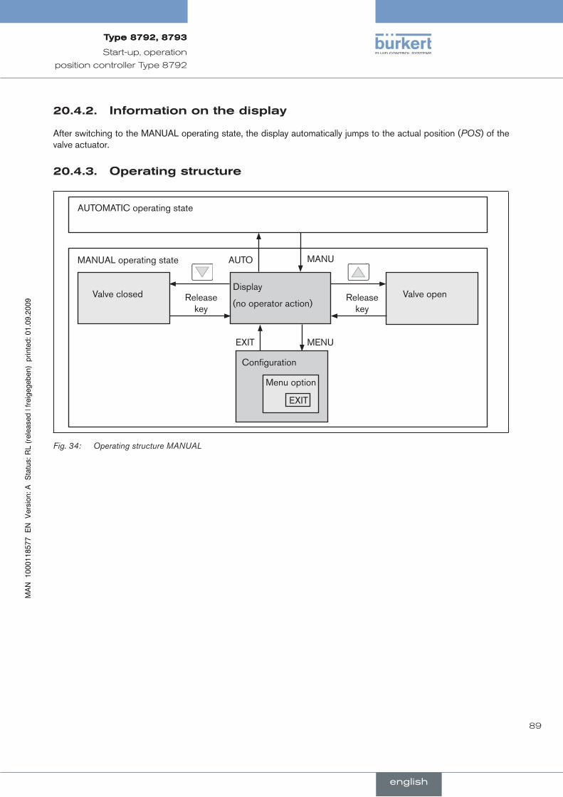
89
Start-up, operation
position controller Type 8792
informationonthedisplay20.4.2.
After switching to the MANUAL operating state, the display automatically jumps to the actual position (POS) of the valve actuator.
Operatingstructure20.4.3.
Configuration
Menu option
EXIT
Display
(no operator action)Valve open
EXIT MENU
AUTOMATIC operating state
MANUAL operating state MANUAUTO
Release key
Release key
Valve closed
Operating structure MANUAL Fig. 34:
english
Type8792,8793Type8792,8793
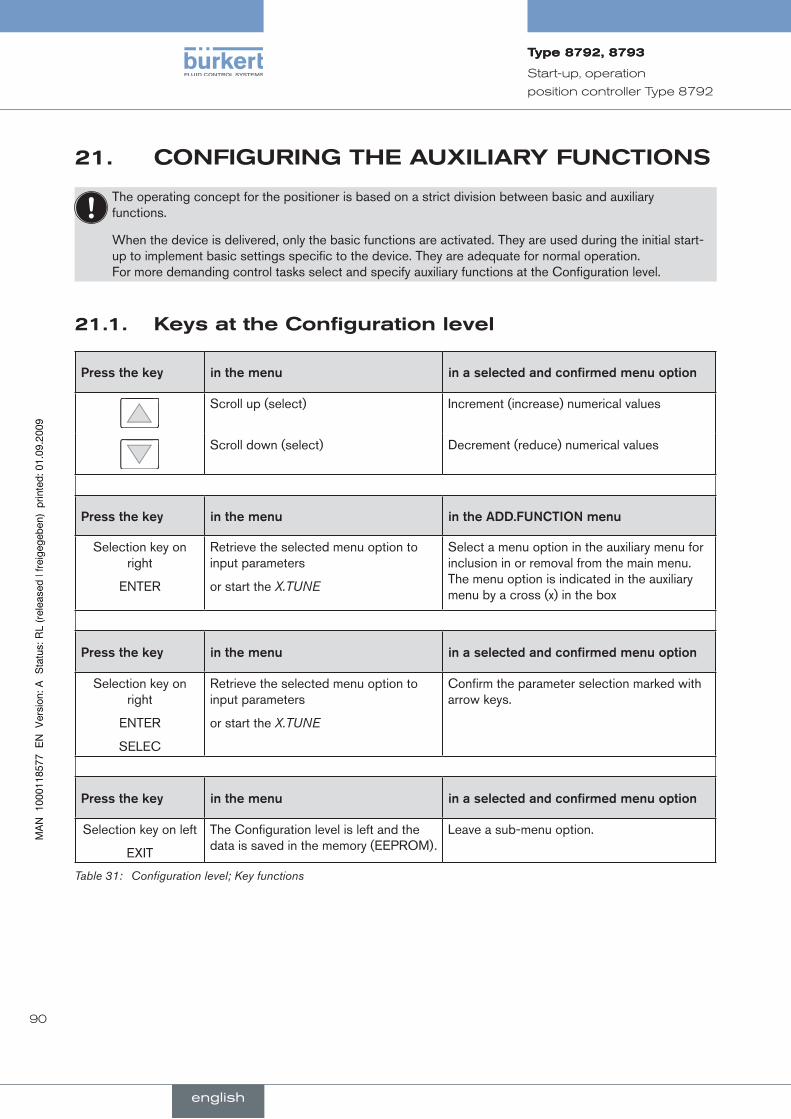
90
Start-up, operation
position controller Type 8792
21. cOnfiguringTheauxiliaryfuncTiOns
The operating concept for the positioner is based on a strict division between basic and auxiliary functions.
When the device is delivered, only the basic functions are activated. They are used during the initial start-up to implement basic settings specific to the device. They are adequate for normal operation. For more demanding control tasks select and specify auxiliary functions at the Configuration level.
Keysattheconfigurationlevel21.1.
Press.the.key in.the.menu in.a.selected.and.confirmed.menu.option
Scroll up (select) Increment (increase) numerical values
Scroll down (select) Decrement (reduce) numerical values
Press.the.key in.the.menu in.the.ADD.FunCTIOn.menu
Selection key on right
ENTER
Retrieve the selected menu option to input parameters
or start the X.TUNE
Select a menu option in the auxiliary menu for inclusion in or removal from the main menu. The menu option is indicated in the auxiliary menu by a cross (x) in the box
Press.the.key in.the.menu in.a.selected.and.confirmed.menu.option
Selection key on right
ENTER
SELEC
Retrieve the selected menu option to input parameters
or start the X.TUNE
Confirm the parameter selection marked with arrow keys.
Press.the.key in.the.menu in.a.selected.and.confirmed.menu.option
Selection key on left
EXIT
The Configuration level is left and the data is saved in the memory (EEPROM).
Leave a sub-menu option.
Configuration level; Key functionsTable 31:
english
Type8792,8793Type8792,8793
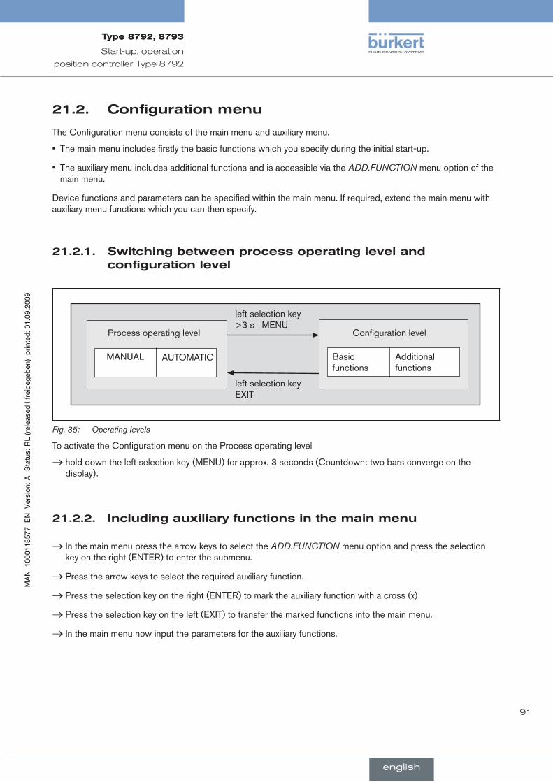
91
Start-up, operation
position controller Type 8792
configurationmenu21.2.
The Configuration menu consists of the main menu and auxiliary menu.
The main menu includes firstly the basic functions which you specify during the initial start-up. •
The auxiliary menu includes additional functions and is accessible via the • ADD.FUNCTION menu option of the main menu.
Device functions and parameters can be specified within the main menu. If required, extend the main menu with auxiliary menu functions which you can then specify.
switchingbetweenprocessoperatingleveland21.2.1.configurationlevel
Process operating level
MANUAL AUTOMATIC Basic functions
Additional functions
Configuration level
left selection key >3 s MENU
left selection key EXIT
Operating levelsFig. 35:
To activate the Configuration menu on the Process operating level
hold down the left selection key (MENU) for approx. 3 seconds (Countdown: two bars converge on the →display).
includingauxiliaryfunctionsinthemainmenu21.2.2.
In the main menu press the arrow keys to select the → ADD.FUNCTION menu option and press the selection key on the right (ENTER) to enter the submenu.
Press the arrow keys to select the required auxiliary function. →
Press the selection key on the right (ENTER) to mark the auxiliary function with a cross (x). →
Press the selection key on the left (EXIT) to transfer the marked functions into the main menu. →
In the main menu now input the parameters for the auxiliary functions. →
english
Type8792,8793Type8792,8793
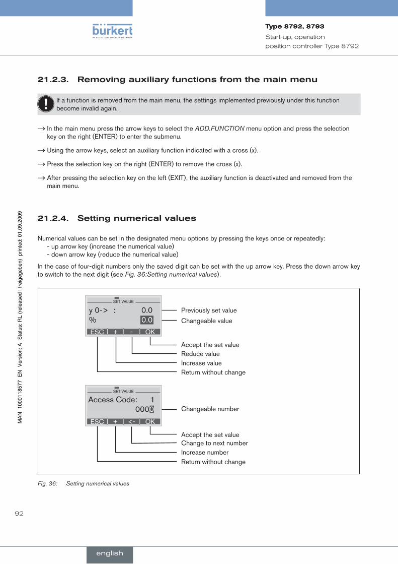
92
Start-up, operation
position controller Type 8792
removingauxiliaryfunctionsfromthemainmenu21.2.3.
If a function is removed from the main menu, the settings implemented previously under this function become invalid again.
In the main menu press the arrow keys to select the → ADD.FUNCTION menu option and press the selection key on the right (ENTER) to enter the submenu.
Using the arrow keys, select an auxiliary function indicated with a cross (x). →
Press the selection key on the right (ENTER) to remove the cross (x). →
After pressing the selection key on the left (EXIT), the auxiliary function is deactivated and removed from the →main menu.
settingnumericalvalues21.2.4.
Numerical values can be set in the designated menu options by pressing the keys once or repeatedly: - up arrow key (increase the numerical value)
- down arrow key (reduce the numerical value)
In the case of four-digit numbers only the saved digit can be set with the up arrow key. Press the down arrow key to switch to the next digit (see Fig. 36:Setting numerical values).
Accept the set value
Return without change
Previously set value
ESC OK+ <-
SET VALUE
Access Code: 1 0000
ESC OK+ -
SET VALUE
y 0 -> : 0.0 % 0.0 Changeable value
Change to next numberIncrease number
Increase valueReduce value
Changeable number
Accept the set value
Return without change
Fig. 36: Setting numerical values
english
Type8792,8793Type8792,8793
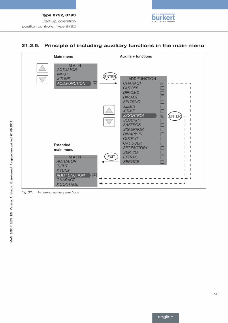
93
Start-up, operation
position controller Type 8792
principleofincludingauxiliaryfunctionsinthemainmenu21.2.5.
ACTUATOR INPUT X.TUNE ADD.FUNCTION
M A I N
ENTER
CHARACT CUTOFF DIR.CMD DIR.ACT SPLTRNG X.LIMIT X.TIME X.CONTROL SECURITY SAFEPOS SIG.ERROR BINARY. IN OUTPUT CAL.USER SET.FACTORY SER. I/O EXTRAS SERVICE
ENTER
EXITM A I N
ADD.FUNKTION
Auxiliary.functionsMain.menu
Extended.main.menu
ACTUATOR INPUT X.TUNE ADD.FUNCTION CHARACT X.CONTROL
Including auxiliary functionsFig. 37:
english
Type8792,8793Type8792,8793
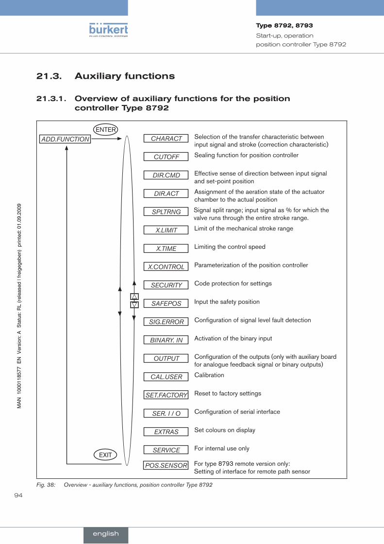
94
Start-up, operation
position controller Type 8792
auxiliaryfunctions21.3.
Overviewofauxiliaryfunctionsfortheposition21.3.1.controllerType8792
POS.SENSOR For type 8793 remote version only: Setting of interface for remote path sensor
ENTERCHARACT
EXIT
ADD.FUNCTION Selection of the transfer characteristic between input signal and stroke (correction characteristic)
CUTOFF Sealing function for position controller
DIR.CMD Effective sense of direction between input signal and set-point position
DIR.ACT Assignment of the aeration state of the actuator chamber to the actual position
SPLTRNG Signal split range; input signal as % for which the valve runs through the entire stroke range.
X.LIMIT Limit of the mechanical stroke range
X.TIME Limiting the control speed
X.CONTROL Parameterization of the position controller
SECURITY Code protection for settings
SAFEPOS Input the safety position
SIG.ERROR Configuration of signal level fault detection
BINARY. IN Activation of the binary input
OUTPUT Configuration of the outputs (only with auxiliary board for analogue feedback signal or binary outputs)
CAL.USER Calibration
SET.FACTORY Reset to factory settings
SER. I / O Configuration of serial interface
EXTRAS Set colours on display
SERVICE For internal use only
Overview - auxiliary functions, position controller Type 8792Fig. 38:
english
Type8792,8793Type8792,8793
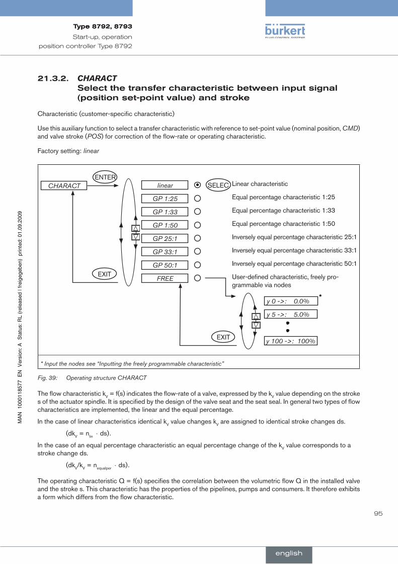
95
Start-up, operation
position controller Type 8792
21.3.2. CHARACT selectthetransfercharacteristicbetweeninputsignal(positionset-pointvalue)andstroke
Characteristic (customer-specific characteristic)
Use this auxiliary function to select a transfer characteristic with reference to set-point value (nominal position, CMD) and valve stroke (POS) for correction of the flow-rate or operating characteristic.
Factory setting: linear
CHARACT SELEClinear
EXIT
ENTER
GP 1:25
GP 1:33
GP 1:50
GP 25:1
GP 33:1
GP 50:1
FREE
y 0 ->: 0.0%
y 5 ->: 5.0%
y 100 ->: 100%EXIT
*
Linear characteristic
Equal percentage characteristic 1:25
Equal percentage characteristic 1:33
Equal percentage characteristic 1:50
Inversely equal percentage characteristic 25:1
Inversely equal percentage characteristic 33:1
Inversely equal percentage characteristic 50:1
User-defined characteristic, freely pro-grammable via nodes
* Input the nodes see “Inputting the freely programmable characteristic”
Operating structure CHARACTFig. 39:
The flow characteristic kV = f(s) indicates the flow-rate of a valve, expressed by the kV value depending on the stroke s of the actuator spindle. It is specified by the design of the valve seat and the seat seal. In general two types of flow characteristics are implemented, the linear and the equal percentage.
In the case of linear characteristics identical kV value changes kV are assigned to identical stroke changes ds.
(dkV = nlin ⋅ ds).
In the case of an equal percentage characteristic an equal percentage change of the kV value corresponds to a stroke change ds.
(dkV/kV = nequalper ⋅ ds).
The operating characteristic Q = f(s) specifies the correlation between the volumetric flow Q in the installed valve and the stroke s. This characteristic has the properties of the pipelines, pumps and consumers. It therefore exhibits a form which differs from the flow characteristic.
english
Type8792,8793Type8792,8793

96
Start-up, operation
position controller Type 8792
Position set-point value [%] CMD
Standardised valve stroke [%] (POS)
CharacteristicsFig. 40:
In the case of control tasks for closed-loop control systems it is usually particular demands which are placed on the course of the operating characteristic, e.g. linearity. For this reason it is occasionally necessary to correct the course of the operating characteristic in a suitable way. For this purpose the positioner features a transfer element which implements different characteristics. These are used to correct the operating characteristic.
Equal percentage characteristics 1:25, 1:33, 1:50, 25:1, 33:1 and 50:1 and a linear characteristic can be set. Furthermore, a characteristic can be freely programmed via nodes or automatically calibrated.
inputtingthefreelyprogrammablecharacteristic21.3.3.
The characteristic is defined via 21 nodes which are distributed uniformly via the position set-point values ranging from 0 – 100%. Their distance is 5%. A freely selectable stroke (adjustment range 0 – 100%) is assigned to each node. The difference between the stroke values of two adjacent nodes must not be larger than 20%.
FREE y 0 ->: 0.0%
y 5 ->: 5.0%
y 100 ->: 100%EXIT
SELEC INPUT+
-y 0 ->: 0.0%OK
INPUT+
-y 5 ->: 5.0%OK
INPUT+
-y 100 ->: 100%OK
*
*
*
* If the sub-menu is left by pressing the selection key on the left (ESC), the value remains unchanged.
Fig. 12: Operating structure CHARACT FREE
english
Type8792,8793Type8792,8793

97
Start-up, operation
position controller Type 8792
Procedure:
To input the characteristic points (function values), select the → FREE sub-menu option using the arrow keys and confirm by pressing the selection key on the right (SELEC).
Another sub-menu (FREE) opens in which the individual nodes are listed (as %).
Select the individual nodes using the arrow keys and confirm by pressing the selection key on the right (INPUT) in →order to change the value in the SET VALUE sub-menu.
ESC OK+ –
SET VALUE
y 0 -> : 0.0 % 0.0
This value (as %) is changed with the arrow keys
Accept the set valueReturn without change
Previously set value (as %)
Display CHARACT FREEFig. 41:
Using the arrow keys (+/-), set the function value from 0 to 100% and confirm by pressing the selection key on →the right (OK).
When all changes have been made, leave the sub-menu by pressing the selection key on the left (EXIT). →
Press the selection key on the left again (EXIT) to return to the → CHARACT menu option.
Changed values are not transferred into the memory (EEPROM) until the main menu (MAIN) is left.
english
Type8792,8793Type8792,8793

98
Start-up, operation
position controller Type 8792
Example.of.a.programmed.characteristic
Valve stroke [&] (POS)
Unit signal [%] (CMD)
10
20
30
40
50
60
70
80
90
100
10 20 30 40 50 60 70 80 90 1000
4 – 20 mA 0 – 20 mA 0 – 10 V 0 – 5 V
Example of a programmed characteristicFig. 42:
In the section “Tables for customer-specific settings” in chapter “Settings of the Freely Program-mable Characteristic” there is a table in which you can enter your settings for the freely programmable characteristic.
english
Type8792,8793Type8792,8793
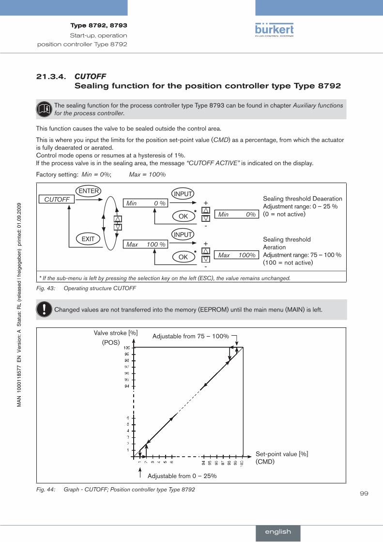
99
Start-up, operation
position controller Type 8792
21.3.4. CUTOFFsealingfunctionforthepositioncontrollertypeType8792
The sealing function for the process controller type Type 8793 can be found in chapter Auxiliary functions for the process controller.
This function causes the valve to be sealed outside the control area.
This is where you input the limits for the position set-point value (CMD) as a percentage, from which the actuator is fully deaerated or aerated. Control mode opens or resumes at a hysteresis of 1%. If the process valve is in the sealing area, the message “CUTOFF ACTIVE” is indicated on the display.
Factory setting: Min = 0%; Max = 100%
CUTOFF Min 0 %
Max 100 %EXIT
ENTER INPUT+
-Min 0%OK
INPUT+
-Max 100%OK
*
*
Sealing threshold Deaeration Adjustment range: 0 – 25 % (0 = not active)
Sealing threshold Aeration Adjustment range: 75 – 100 % (100 = not active)
* If the sub-menu is left by pressing the selection key on the left (ESC), the value remains unchanged.
Operating structure CUTOFFFig. 43:
Changed values are not transferred into the memory (EEPROM) until the main menu (MAIN) is left.
Valve stroke [%] Adjustable from 75 – 100%
Set-point value [%](CMD)
Adjustable from 0 – 25%
(POS)
Graph - CUTOFF; Position controller type Type 8792Fig. 44:
english
Type8792,8793Type8792,8793
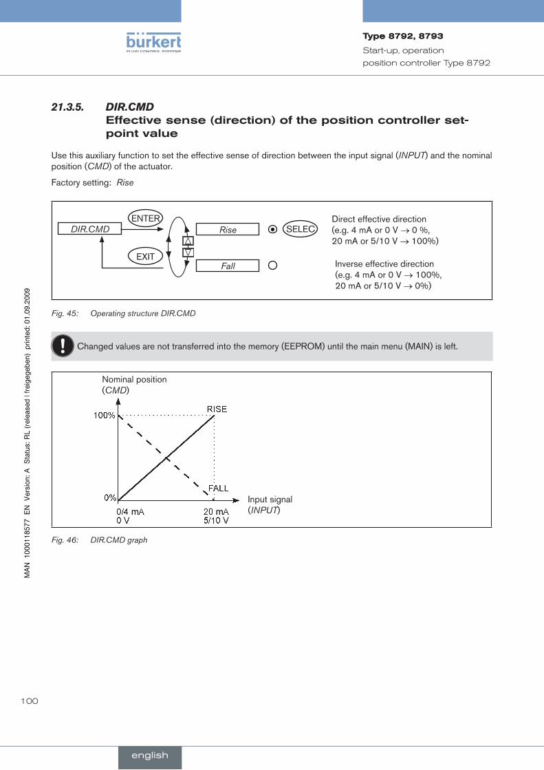
100
Start-up, operation
position controller Type 8792
DIR.CMD21.3.5. effectivesense(direction)ofthepositioncontrollerset-pointvalue
Use this auxiliary function to set the effective sense of direction between the input signal (INPUT) and the nominal position (CMD) of the actuator.
Factory setting: Rise
DIR.CMDENTER
SELECRise
EXITFall
Direct effective direction (e.g. 4 mA or 0 V → 0 %, 20 mA or 5/10 V → 100%)
Inverse effective direction (e.g. 4 mA or 0 V → 100%, 20 mA or 5/10 V → 0%)
Operating structure DIR.CMDFig. 45:
Changed values are not transferred into the memory (EEPROM) until the main menu (MAIN) is left.
Nominal position (CMD)
Input signal (INPUT)
DIR.CMD graphFig. 46:
english
Type8792,8793Type8792,8793
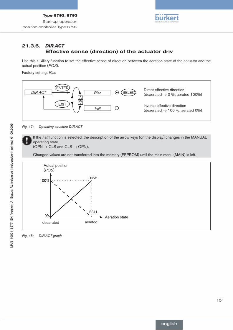
101
Start-up, operation
position controller Type 8792
21.3.6. DIR.ACTeffectivesense(direction)oftheactuatordriv
Use this auxiliary function to set the effective sense of direction between the aeration state of the actuator and the actual position (POS).
Factory setting: Rise
ENTERSELECRise
EXITFall
DIR.ACTDirect effective direction (deaerated → 0 %; aerated 100%)
Inverse effective direction (deaerated → 100 %; aerated 0%)
Operating structure DIR.ACTFig. 47:
If the Fall function is selected, the description of the arrow keys (on the display) changes in the MANUAL operating state (OPN → CLS and CLS → OPN).
Changed values are not transferred into the memory (EEPROM) until the main menu (MAIN) is left.
Actual position (POS)
Aeration statedeaerated aerated
DIR.ACT graph Fig. 48:
english
Type8792,8793Type8792,8793

102
Start-up, operation
position controller Type 8792
21.3.7. SPLTRNG signalsplitrange
Min. and max. values of the input signal as % for which the valve runs through the entire stroke range.
Factory setting: Min = 0%; Max = 100%
This function is effective only im Betrieb as a position controller.
Use this auxiliary function to limit the position set-point value range of the positioner by specifying a minimum and a maximum value.
As a result, it is possible to divide a utilised unit signal range (4 – 20 mA; 0 – 20 mA; 0 – 10 V or 0 – 5 V) into several positioners (without or with overlapping).
This allows several valves to be used alternately or in the case of overlapping set-point value ranges simultane-ously as actuators.
ENTERSPLTRNG Min 0 %
Max 100 %EXIT
INPUT+
-Min 0 %OK
INPUT+
-Max 100 %OK
*
*
Input the minimum value of the input signal as %
Adjustment range: 0 – 75 %
Input the maximum value of the input signal as %
Adjustment range: 25 – 100 %
* If the sub-menu is left by pressing the selection key on the left (ESC), the value remains unchanged.
Operating structure SPLTRNGFig. 49:
Changed values are not transferred into the memory (EEPROM) until the main menu (MAIN) is left.
english
Type8792,8793Type8792,8793

103
Start-up, operation
position controller Type 8792
Splitting.a.unit.signal.range.into.two.set-point.value.ranges
Valve stroke [%] (POS)
Set-point value [mA] (INP)
Set-point value range Position controller 1
Set-point value range Position controller 2
SPLTRNG graph Fig. 50:
english
Type8792,8793Type8792,8793

104
Start-up, operation
position controller Type 8792
21.3.8. X.LIMITlimitsthemechanicalstrokerange
This auxiliary function limits the (physical) stroke to specified % values (minimum and maximum). In doing so, the stroke range of the limited stroke is set equal to 100%.
If the limited stroke range is left during operation, negative POS values or POS values greater than 100% are indicated.
Factory setting: Min = 0%, Max = 100%
ENTERMin 0%
Max 100%EXIT
INPUT+
-Min 0%OK
INPUT+
-Max 100%OK
*
*
X.LIMITInput the initial value of the stroke range as %
Adjustment range: 0 – 50% of the total stroke
Input the final value of the stroke range as %,
Adjustment range: 50 – 100% of the total stroke
The minimum gap between Min and Max is 50%
* If the sub-menu is left by pressing the selection key on the left (ESC), the value remains unchanged.
Operating structure X.LIMITFig. 51:
Changed values are not transferred into the memory (EEPROM) until the main menu (MAIN) is left.
Limited stroke
Unlimited stroke
Physical stroke (%) (POS)
Limited stroke (%) (POS)
Set-point value [mA] (INPUT)
Adj
ustm
ent r
ange
in M
AN
UA
L m
ode
Con
trol
rang
e in
AU
TO-
MAT
IC m
ode
X.LIMIT graphFig. 52:
english
Type8792,8793Type8792,8793
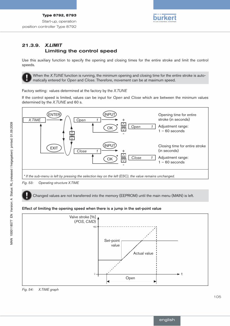
105
Start-up, operation
position controller Type 8792
21.3.9. X.LIMITlimitingthecontrolspeed
Use this auxiliary function to specify the opening and closing times for the entire stroke and limit the control speeds.
When the X.TUNE function is running, the minimum opening and closing time for the entire stroke is auto-matically entered for Open and Close. Therefore, movement can be at maximum speed.
Factory setting: values determined at the factory by the X.TUNE
If the control speed is limited, values can be input for Open and Close which are between the minimum values determined by the X.TUNE and 60 s.
ENTER
EXIT
INPUT+
-OK
INPUT+
-OK
*
*
X.TIME Open 1
Close 1
Open 1
Close 1
Opening time for entire stroke (in seconds)
Adjustment range: 1 – 60 seconds
Closing time for entire stroke (in seconds)
Adjustment range: 1 – 60 seconds
* If the sub-menu is left by pressing the selection key on the left (ESC), the value remains unchanged.
Operating structure X.TIMEFig. 53:
Changed values are not transferred into the memory (EEPROM) until the main menu (MAIN) is left.
Effect.of.limiting.the.opening.speed.when.there.is.a.jump.in.the.set-point.value
Set-point value
Actual value
Opent
Valve stroke [%] (POS, CMD)
X.TIME graphFig. 54:
english
Type8792,8793Type8792,8793

106
Start-up, operation
position controller Type 8792
21.3.10.X.CONTROLparameterizationofthepositioncontroller
Use this function to set the parameters for the position controller (dead band and amplification factors).
X.CONTROL DBND 1%
KXopn 1
KXcls 1
EXIT
ENTER INPUT+
-DBND 1%
INPUT+
-KXopn 0001
INPUT+
-KXcls 0001
OK*
OK*
OK*
* If the sub-menu is left by pressing the selection key on the left (ESC), the value remains unchanged.
Operating structure X.CONTROLFig. 55:
DBnD.. . .Insensitivity.range.(dead.band).of.the.position.controller.
Input the dead band as %, relating to the scaled stroke range; i.e. X.LIMIT Max - X.LIMIT Min (see Auxiliary function 21.3.8.X.LIMIT Limits the mechanical stroke range).
This function causes the controller to respond only from a specific control difference; as a result the solenoid valves in the positioner and the pneumatic actuator are protected.
If the auxiliary function X.CONTROL is in the main menu while X.TUNE (Autotune of the position con-troller) is running, the dead band DBND is determined automatically depending on the friction behaviour of the actuator drive. The guide value determined in this way can be re-adjusted manually.
Position set-point value
Control difference
Xd1
Position actual value
to the controller
Xd1‘
Dead band
Xd1
Xd1‘
X.CONTROL graphFig. 56:
KX XXX Parameter of the position controller KXopn Amplification factor of the position controller (for closing the valve) KXcls Amplification factor of the position controller (for opening the valve)
english
Type8792,8793Type8792,8793

107
Start-up, operation
position controller Type 8792
21.3.11.SECURITYcodeprotectionforthesettings
Use the SECURITY function to prevent the positioner or individual functions from being accessed unintentionally.
Factory setting: Access Code: 0000
If the code protection is activated, the code (set access code or master code) must be input whenever operator action is disabled.
All operator actions can be implemented with the non-changeable master code. This 4-digit master code can be found in the appendix of these operating instructions in the chapter entitled “Master code”.
SECURITY
CODE
EXIT
ENTER
OK
SELEC
INPUT
ESC OK+ <-
MAIN
MANU/AUTO
ADDFUNCT
X.TUNE
SET VALUE
Access Code: 1 0000
①
②③④⑤
Operating structure SECURITY, position controller type Type 8792Fig. 57:
①Input screen for inputting or changing the access code (for description of input see below)
②Blocking access to the configuration level
③Blocking switchover between the MANUAL / AUTOMATIC (MANU/AUTO) operating states
④Blocking the input of auxiliary function
⑤Blocking the activation of self-parameterization (Autotune)
Inputting.the.access.code:
To access the input screen with marked selection menu CODE, press the selection key on the right (INPUT). →
ESC OK+ <-
SET VALUE
Access Code: 1 0000
The four-digit code can be changed via the arrow keys.
Down arrow key (←) Select the individual digits. Up arrow key (+) Change the selected digit.
Left selection button (ESC) Leave the input screen without making a change.
Right selection button (OK) Leave the input screen saving the input or making a change.
english
Type8792,8793Type8792,8793
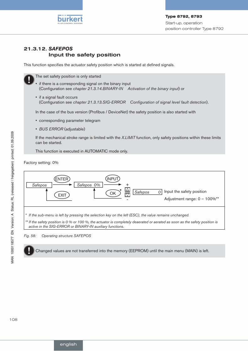
108
Start-up, operation
position controller Type 8792
21.3.12.SAFEPOS inputthesafetyposition
This function specifies the actuator safety position which is started at defined signals.
The set safety position is only started
if there is a corresponding signal on the binary input • (Configuration see chapter 21.3.14.BINARY-IN Activation of the binary input) or
if a signal fault occurs • (Configuration see chapter 21.3.13.SIG-ERROR Configuration of signal level fault detection).
In the case of the bus version (Profibus / DeviceNet) the safety position is also started with
corresponding parameter telegram•
BUS ERROR• (adjustable)
If the mechanical stroke range is limited with the X.LIMIT function, only safety positions within these limits can be started.
This function is executed in AUTOMATIC mode only.
Factory setting: 0%
Safepos Safepos 0%
EXIT
ENTER INPUT+
-Safepos 0OK
* Input the safety position
Adjustment range: 0 – 100%**
* If the sub-menu is left by pressing the selection key on the left (ESC), the value remains unchanged.
** If the safety position is 0 % or 100 %, the actuator is completely deaerated or aerated as soon as the safety position is active in the SIG-ERROR or BINARY-IN auxiliary functions.
Operating structure SAFEPOSFig. 58:
Changed values are not transferred into the memory (EEPROM) until the main menu (MAIN) is left.
english
Type8792,8793Type8792,8793
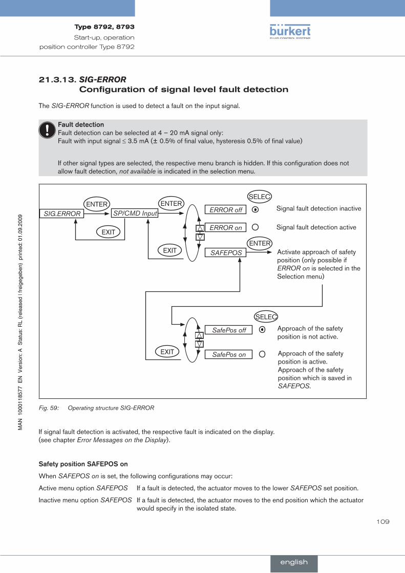
109
Start-up, operation
position controller Type 8792
21.3.13.SIG-ERROR configurationofsignallevelfaultdetection
The SIG-ERROR function is used to detect a fault on the input signal.
Fault.detection.Fault detection can be selected at 4 – 20 mA signal only: Fault with input signal ≤ 3.5 mA (± 0.5% of final value, hysteresis 0.5% of final value)
If other signal types are selected, the respective menu branch is hidden. If this configuration does not allow fault detection, not available is indicated in the selection menu.
SIG.ERRORENTER
SELEC
ERROR off
EXIT SAFEPOS
Signal fault detection inactive
Activate approach of safety position (only possible if ERROR on is selected in the Selection menu)
SP/CMD Input
ERROR on Signal fault detection active
SELEC
SafePos off Approach of the safety position is not active.
SafePos on Approach of the safety position is active. Approach of the safety position which is saved in SAFEPOS.
EXIT
EXIT
ENTER
ENTER
Operating structure SIG-ERRORFig. 59:
If signal fault detection is activated, the respective fault is indicated on the display. (see chapter Error Messages on the Display).
Safety.position.SAFEPOS.on
When SAFEPOS on is set, the following configurations may occur:
Active menu option SAFEPOS If a fault is detected, the actuator moves to the lower SAFEPOS set position.
Inactive menu option SAFEPOS If a fault is detected, the actuator moves to the end position which the actuator would specify in the isolated state.
english
Type8792,8793Type8792,8793

110
Start-up, operation
position controller Type 8792
21.3.14.BINARY-INactivationofthebinaryinput
This function activates the binary input.
The following settings can be implemented for this:
Approaching the safety position or•
Switching over the MANUAL/AUTOMATIC operating mode•
SELEC
SafePos
EXIT BIN.IN type
Safety position
Selection Type of the binary input
BINARY-INENTER
MANU/AUTO
ENTER
Operating mode switchover
SELEC
normally open normally closed (0 – 5 V = 1; 10 – 30 V = 0)
normally closed normally open (0 – 5 V = 0; 10 – 30 V = 1)
EXIT
Operating structure BINARY-INFig. 60:
SAFEPOS.safety.position
Approaching a safety position:
Active menu option SAFEPOS The actuator moves to the lower SAFEPOS set position.
Inactive SAFEPOS menu option The actuator moves to the end position which it would specify in the isolated state.
Operating.mode.switchover.MAnu/AuTO
Switch over the operating state to MANUAL or AUTOMATIC:
Binary input = 0 → AUTOMATIC operating mode
Binary input = 1 → MANUAL operating mode
If operating mode switchover is selected, you can no longer switch over the operating mode via the selection key on the right (MANU/AUTO).
english
Type8792,8793Type8792,8793
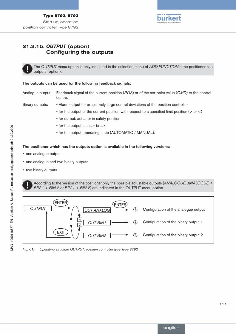
111
Start-up, operation
position controller Type 8792
21.3.15.OUTPUT(option) configuringtheoutputs
The OUTPUT menu option is only indicated in the selection menu of ADD.FUNCTION if the positioner has outputs (option).
The.outputs.can.be.used.for.the.following.feedback.signals:
Analogue output: Feedback signal of the current position (POS) or of the set-point value (CMD) to the control centre.
Binary outputs: • Alarm output for excessively large control deviations of the position controller
• for the output of the current position with respect to a specified limit position (> or <)
• for output: actuator in safety position
• for the output: sensor break
• for the output: operating state (AUTOMATIC / MANUAL).
The.positioner.which.has.the.outputs.option.is.available.in.the.following.versions:
one analogue output•
one analogue and two binary outputs•
two binary outputs•
According to the version of the positioner only the possible adjustable outputs (ANALOGUE, ANALOGUE + BIN 1 + BIN 2 or BIN 1 + BIN 2) are indicated in the OUTPUT menu option.
OUTPUT OUT ANALOG
OUT BIN2EXIT
ENTER ENTERConfiguration of the analogue output
OUT BIN1 Configuration of the binary output 1
Configuration of the binary output 2
①
②
③
Operating structure OUTPUT; position controller type Type 8792Fig. 61:
english
Type8792,8793Type8792,8793
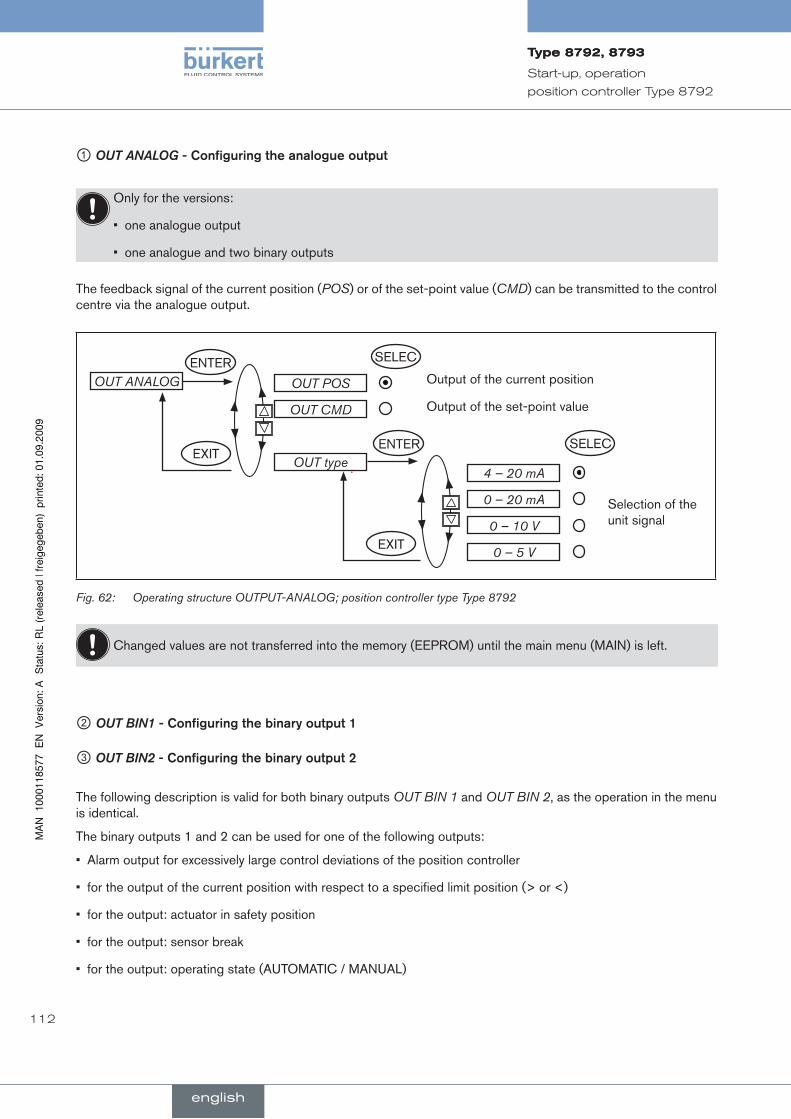
112
Start-up, operation
position controller Type 8792
① OUT ANALOG -.Configuring.the.analogue.output
Only for the versions:
one analogue output•
one analogue and two binary outputs•
The feedback signal of the current position (POS) or of the set-point value (CMD) can be transmitted to the control centre via the analogue output.
OUT POS
EXITOUT type
Output of the current positionOUT ANALOG
OUT CMD Output of the set-point value
4 – 20 mA
Selection of the unit signal
0 – 20 mA
0 – 10 V
0 – 5 V
ENTER SELEC
SELECENTER
EXIT
Operating structure OUTPUT-ANALOG; position controller type Type 8792Fig. 62:
Changed values are not transferred into the memory (EEPROM) until the main menu (MAIN) is left.
② OUT BIN1 -.Configuring.the.binary.output.1
③ OUT BIN2 -.Configuring.the.binary.output.2
The following description is valid for both binary outputs OUT BIN 1 and OUT BIN 2, as the operation in the menu is identical.
The binary outputs 1 and 2 can be used for one of the following outputs:
Alarm output for excessively large control deviations of the position controller•
for the output of the current position with respect to a specified limit position (> or <)•
for the output: actuator in safety position•
for the output: sensor break•
for the output: operating state (AUTOMATIC / MANUAL)•
english
Type8792,8793Type8792,8793
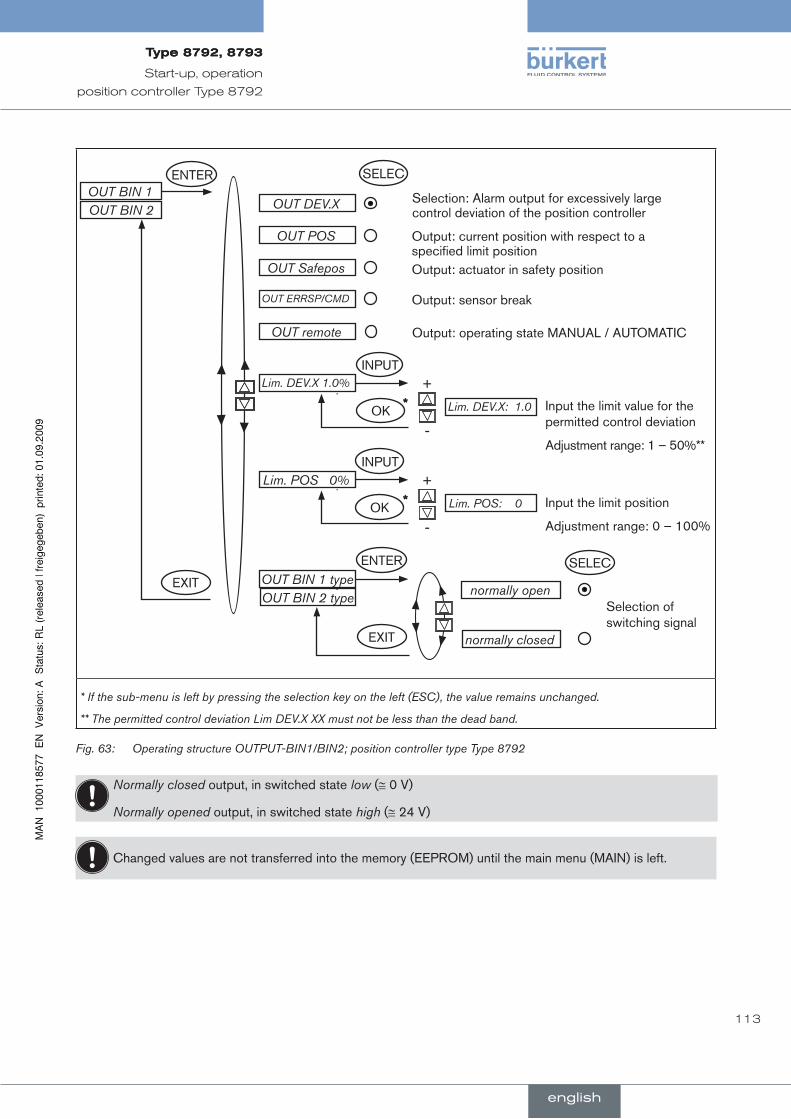
113
Start-up, operation
position controller Type 8792
OUT DEV.X
Lim. DEV.X 1.0%
Selection: Alarm output for excessively large control deviation of the position controller
OUT BIN 1
OUT POS Output: current position with respect to a specified limit position
OUT Safepos Output: actuator in safety position
OUT ERRSP/CMD Output: sensor break
INPUT+
-Lim. DEV.X: 1.0OK
* Input the limit value for the permitted control deviation
Adjustment range: 1 – 50%**
Lim. POS 0%INPUT
+
-Lim. POS: 0* Input the limit position
Adjustment range: 0 – 100%
OUT BIN 1 typenormally open
Selection of switching signal
normally closed
OUT BIN 2
OUT BIN 2 type
OUT remote Output: operating state MANUAL / AUTOMATIC
EXIT
ENTER
SELECENTER
EXIT
SELEC
OK
* If the sub-menu is left by pressing the selection key on the left (ESC), the value remains unchanged.
** The permitted control deviation Lim DEV.X XX must not be less than the dead band.
Operating structure OUTPUT-BIN1/BIN2; position controller type Type 8792Fig. 63:
Normally closed output, in switched state low (≅ 0 V)
Normally opened output, in switched state high (≅ 24 V)
Changed values are not transferred into the memory (EEPROM) until the main menu (MAIN) is left.
english
Type8792,8793Type8792,8793

114
Start-up, operation
position controller Type 8792
OUT DEV.X..Alarm.output.for.excessively.large.control.deviation.of.the.position.controller:
Press the arrow keys to mark the → OUT DEV.X menu option and confirm with the selection key on the right (SELEC).
Press the arrow keys to input the → the limit value for the permitted control deviation in the Lim. DEV.X menu option and accept with the selection key on the right (OK).
The permitted control deviation Lim. DEV.X XX must not be less than the dead band.
In the → OUT BIN1/2 type menu option input the required switching status (normally open / normally closed) (see Table 32:).
OUT POS . Output.of.the.current.position.with.respect.to.a.specified.limit.position:
Press the arrow keys to mark the → OUT POS menu option and confirm with the selection key on the right (SELEC).
Press the arrow keys to input the → value of the limit position in the Lim. POS 0% menu option and accept with the selection key on the right (OK).
In the → OUT BIN1/2 type menu option input the required switching status (normally open / normally closed) (see Table 32:).
OUT BIN1/2 normally open* normally closed**
POS > LIM 0 V 24 V
POS < LIM 24 V 0 V
* Normally open- output, in switched state high (≅ 24 V)
** Normally closed- output, in switched state low (≅ 0 V)
Table 32: Switching status OUT BIN - POS > LIM; position controller type Type 8792
english
Type8792,8793Type8792,8793
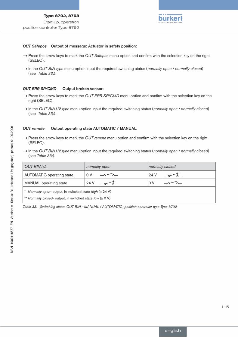
115
Start-up, operation
position controller Type 8792
OUT Safepos. Output.of.message:.Actuator.in.safety.position:.
Press the arrow keys to mark the → OUT Safepos menu option and confirm with the selection key on the right (SELEC).
In the → OUT BIN type menu option input the required switching status (normally open / normally closed) (see Table 33:).
OUT ERR SP/CMD.. Output.broken.sensor:
Press the arrow keys to mark the → OUT ERR SP/CMD menu option and confirm with the selection key on the right (SELEC).
In the → OUT BIN1/2 type menu option input the required switching status (normally open / normally closed) (see Table 33:).
OUT remote.. Output.operating.state.AuTOMATIC./.MAnuAl:
Press the arrow keys to mark the → OUT remote menu option and confirm with the selection key on the right (SELEC).
In the → OUT BIN1/2 type menu option input the required switching status (normally open / normally closed) (see Table 33:).
OUT BIN1/2 normally open normally closed
AUTOMATIC operating state 0 V 24 V
MANUAL operating state 24 V 0 V
* Normally open- output, in switched state high (≅ 24 V)
** Normally closed- output, in switched state low (≅ 0 V)
Table 33: Switching status OUT BIN - MANUAL / AUTOMATIC; position controller type Type 8792
english
Type8792,8793Type8792,8793

116
Start-up, operation
position controller Type 8792
21.3.16.CAL.USER calibratingtheactualvaluedisplayandtheinputsforthepositionset-pointvalue
The following points can be manually calibrated with this function:
Position display (• POS) 0 – 100%
Position set-point value display (• INPUT)
ENTER ENTER
EXIT
calibr. POSCAL. USER OPN
CLS
POS lower 0POS lower 0
INPUT
OK*
OPN
CLS
POS upper 0POS upper 0
*
calibr. INPINP 4mA 0
INP 4mA 0***
INP 20mA 0INP 20mA 0**
*
copyFACT->USERRUN
Press forapprox. 3 s
Reset the settings of CAL.USER to factory settings
ENTER
INPUT
INPUT
INPUTEXIT
EXIT
OK
OK
OK
* If the sub-menu is left by pressing the selection key on the left (ESC), the value remains unchanged.
** The signal type is displayed which is selected in the INPUT menu (4 – 20 mA; 0 – 20 mA; 0 – 5 V; 0 – 10 V).
Operating structure CAL.USER; position controller type Type 8792Fig. 64:
Remove the CAL.USER auxiliary function to re-activate the factory calibration.
english
Type8792,8793Type8792,8793

117
Start-up, operation
position controller Type 8792
procedure:
calibr. POS..Calibrating.the.actual.value.display.POS.(0.–.100%):
In the → CAL. USER menu press the arrow keys to select the calibr. POS and confirm with the selection key on the right (ENTER).
Accept the minimum position:
Press the arrow keys to mark the → POS lower X menu option and confirm with the selection key on the right (SELEC).
Approach the minimum position of the valve using the arrow keys (OPN/CLS) and confirm this value by pressing →the selection key on the right (OK).
Accept the maximum position:
Press the arrow keys to mark the → POS upper X menu option and confirm with the selection key on the right (SELEC).
Approach the maximum position of the valve using the arrow keys (OPN/CLS) and confirm this value by pressing →the selection key on the right (OK).
calibr. INP.. Calibrating.the.position.set-point.value.(4.–.20.mA;.0.–.20.mA;.0.–.5.V;.0.–.10.V):
In the → CAL. USER menu press the arrow keys to select the calibr. INP and confirm with the selection key on the right (ENTER).
Accept the minimum input signal (0 mA; 4 mA; 0 V):
Using the arrow keys, select the → INP (0 mA; 4 mA; 0 V) menu option and confirm with the selection key on the right (INPUT).
Specify the minimum value of the unit signal at the input and confirm this value with the selection key on the →right (OK).
Accept the maximum input signal (20 mA; 5 V; 10 V):
Using the arrow keys, select the → INP (20 mA; 5 V; 10 V) menu option and confirm with the selection key on the right (INPUT).
Specify the maximum value of the unit signal at the input and confirm this value with the selection key on the →right (OK).
copy FACT→USER.. resetting.the.settings.under.CAl.uSEr.to.the.factory.settings:.
In the → CAL.USER menu select the copy FACT→USER menu option using the arrow keys and confirm with the selection key on the right (ENTER).
Hold down the selection key on the right (RUN) (for approx. 3 seconds) until the countdown has elapsed. →
english
Type8792,8793Type8792,8793

118
Start-up, operation
position controller Type 8792
21.3.17.SET.FACTORY resettingtothefactorysettings
This function allows all settings implemented by the user to be reset to the delivery status.
All EEPROM parameters with the exception of the calibration values are reset to default values. Then a hardware reset is implemented.
SET.FACTORYRUN press for
approx. 3 s factory reset
Operating structure SET.FACTORYFig. 65:
To activate the → SET.FACTORY function, hold down the selection key on the right (RUN) for approx. 3 s until the countdown has elapsed.
To adjust the positioner to the operating parameters, re-implement self-parameterization of the position controller (X.TUNE).
english
Type8792,8793Type8792,8793
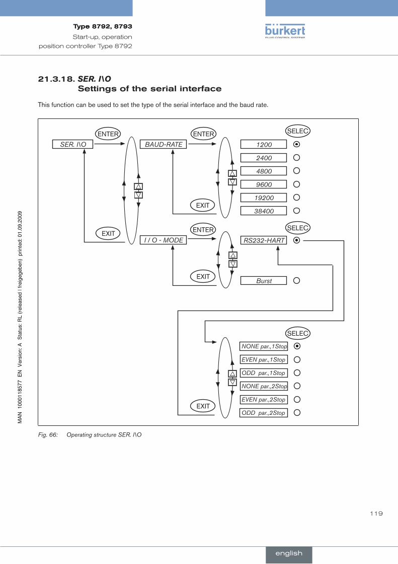
119
Start-up, operation
position controller Type 8792
21.3.18.SER.I\O settingsoftheserialinterface
This function can be used to set the type of the serial interface and the baud rate.
SER. I\O BAUD-RATE
I / O - MODE
1200
2400
4800
9600
19200
38400
RS232-HART
Burst
NONE par.,1Stop
EVEN par.,1Stop
ODD par.,1Stop
NONE par.,2Stop
EVEN par.,2Stop
ODD par.,2Stop
ENTER
ENTERENTER SELEC
SELEC
SELEC
EXIT
EXIT
EXIT
EXIT
Operating structure SER. I\OFig. 66:
english
Type8792,8793Type8792,8793

120
Start-up, operation
position controller Type 8792
21.3.19.EXTRAS
This function can be used to set the representation on the display.
normalBlack font on light backgroundEXTRAS
invers White font on dark background
DISPLAY
ENTER ENTER
EXIT
SELEC
Operating structure EXTRASFig. 67:
21.3.20.POS.SENSOR
The remote model of the process controller type 8793 can be connected to the path sensor by means of different interfaces (the position controller type 8792 remote model with digital interface only).
The POS.SENSOR menu option does not appear in the ADD.FUNCTION selection menu unless a process controller type 8793 is a remote model.
If the ANALOG interface setting is selected, the positioner can be operated as a position controller only and no longer as a process controller.
The P:CONTROL menu option is removed automatically.
POS.SENSOR DIGITAL
EXIT
ENTER ENTERThe position signal of the path sensor is transmitted digitally
ANALOG The position signal of the path sensor is transmitted analogically
①
②
Operating structure POS.SENSORBild 1:
①Digital interface (menu option POS.SENSOR → DIGITAL): The positioner is connected to the path sensor type 8791 via a digital interface (see chapter 17.2.4.).
②Analog interface (menu point POS.SENSOR → ANALOG): The positioner is connected via a 4 – 20 mA interface to any path sensor with a 4 – 20 mA output signal.
If the path sensor requires an additional power supply voltage of 24 V DC, this can be supplied via the posi-tioner (see chapter 17.3.1..
21.3.21.SERVICE
This function is of no importance to the operator of the positioner. It is for internal use only.
english
Type8792,8793Type8792,8793
121
conTenTs
22.. STArTInG.uP.AnD.ADjuSTInG.ThE.PrOCESS.COnTrOllEr............................................................................ 123
22.1.. Safety.instructions........................................................................................................................................................... 123
22.2.. Installation............................................................................................................................................................................ 123
22.3.. Procedure.for.specifying.the.settings................................................................................................................... 123
22.4.. Factory.settings.of.the.process.controller.......................................................................................................... 124
22.5.. Procedure.for.setting.up.a.process.control....................................................................................................... 125
22.6.. Setting.up.the.position.controller.. .................................................................................................................. 126
22.7.. Setting.up.the.process.controller............................................................................................................................ 126
22.7.1. P.CONTROLStarting the auxiliary function ................................................ 126
22.7.2. P.CONTROLBasic settings for the function ............................................... 127
22.7.3. P.Q’LINLinearization of the process characteristic ...................................................... 141
22.7.4. P.TUNE Self-optimization of the process controller (process tune) ...................... 142
23.. OPErATIOn.OF.ThE.PrOCESS.COnTrOllEr............................................................................................................... 145
23.1.. Switching.between.the.operating.states............................................................................................................. 145
23.2.. Switching.between.the.operating.levels.............................................................................................................. 146
23.3.. AuTOMATIC.operating.state....................................................................................................................................... 146
23.3.1. Meaning of the keys .......................................................................................................................... 146
23.3.2. Information on the display ................................................................................................................ 147
23.3.3. Operating structure ........................................................................................................................... 147
23.3.4. Manually Changing the Process Set-Point Value ....................................................................... 148
23.4.. MAnuAl.operating.state.............................................................................................................................................. 148
23.4.1. Meaning of the keys .......................................................................................................................... 148
23.4.2. Information on the display ................................................................................................................ 149
23.4.3. Operating structure ........................................................................................................................... 149
Start-up and operation of the position controller type 8793
english
Type8792,8793

122
Start-up, operation
process controller Type 8793
24.. AuxIlIArY.FunCTIOnS.FOr.ThE.PrOCESS.COnTrOllEr.................................................................................. 150
24.1.. Overview.of.the.auxiliary.functions......................................................................................................................... 150
24.1.1. Including auxiliary functions in the main menu ............................................................................ 151
24.1.2. Removing auxiliary functions from the main menu ...................................................................... 151
24.2. CUTOFFSealing.function.for.the.position.controller.Type.8793........................................................ 152
24.3. SECURITYCode.protection.for.the.settings.................................................................................................. 154
24.4.. SIG-ERRORConfiguration.of.signal.level.fault.detection...................................................................... 156
24.5. OUTPUT.(option)Configuring.the.outputs...................................................................................................... 157
24.6. CAL.USERCalibrating.the.actual.value.display.and.the.inputs.for.the.process.values........ 162
english
Type8792,8793
english
123
Start-up, operation
process controller Type 8793
22. sTarTingupandadjusTingTheprOcesscOnTrOller
safetyinstructions22.1.
danGer!
risk.of.injury.from.high.pressure.in.the.equipment!
Before loosening the lines and valves, turn off the pressure and vent the lines.•
WarnInG!
risk.of.injury.from.improper.start-up!
Start-up may be carried out by authorised technicians only and with the appropriate tools!•
risk.of.injury.from.unintentional.activation.of.the.system.and.an.uncontrolled.restart!
Secure system from unintentional activation.•
Following start-up, ensure a controlled restart.•
installation22.2.
Before start-up, carry out fluid and electrical installation of the positioner and valve..→
To set up the positioner as a process controller, it is first necessary to specify the basic functions of the position controller and then supplement the auxiliary functions for the process control.
procedureforspecifyingthesettings22.3.
When the operating voltage has been switched on, the positioner is at the process operating level in the AUTOMATIC operating state.
To specify the standard settings, switch to the configuration level.
Hold down the left selection key (MENU) for approx. 3 seconds (wait for countdown on display)..→
Then the main menu is indicated on the display (MAIN).
Use the arrow keys to switch between the main menu options and select a menu. .→
Press the right selection key (ENTER/RUN) to confirm the selection..→
Depending on the function, a menu sub-option or a selection screen is indicated on the display.
Use the arrow keys to switch between the submenu options and select the required settings.
Press the right selection key (SELEC/ENTER) to confirm the selection (the dot after the selected parameter is .→now marked).
english
Type8792,8793
english

124
Start-up, operation
process controller Type 8793
To return to the main menu, press the left selection key (EXIT). .→
To save the changed settings, leave the configuration level by pressing the left selection key (EXIT)..→
The positioner is now back on the process operating level.
Only when you leave the configuration level by pressing the right selection key, are the changed param-eters and settings saved (“save EEPROM”).
factorysettingsoftheprocesscontroller22.4.
Function Factory setting Function Factory setting
P.CONTROL
PARAMETER
DBND 1.0%
KP 1.00
TN 999.9
TV 0.0
X0 0.0%
FILTER 0
SETUP
PV-INPUT 4 – 20 mA
PV SCALE PVmin 0.0
PVmax 100.0
SP-INPUT internal
P.CO-INIT bumpless
Factory settings; process controller Type 8793Table 34:
The factory settings of the position controller can be found in chapter Factory settings of the position controller.
english
Type8792,8793
english

125
Start-up, operation
process controller Type 8793
procedureforsettingupaprocesscontrol22.5.
The.process.control.cannot.be.implemented.until.the.position.controller.has.been.automatically.adjusted.(X.TUNE)!
To operate the positioner as a process controller, implement the following steps in the indicated sequence:
Setting.up.the.position.controller:
Specify the basic settings of the positioner and implement automatic adjustment of the position con-.→troller (X.TUNE).
Setting.up.the.process.controller:
Start the .→ P.CONTROL auxiliary function via the configuration menu in the main menu. The P.CONTROL function also inserts the P.Q’LIN and P.TUNE function into the main menu.
Implement the basic settings for the process controller under .→ P.CONTROL.
Linearization of the process characteristic
Implement the P.Q’LIN function..→
Self-optimization of the process controller
Activate the .→ P.TUNE function.
english
Type8792,8793
english

126
Start-up, operation
process controller Type 8793
settingupthepositioncontroller22.6.
Specification of the basic settings is described in the chapter entitled Start-up and operation of the position controller Type 8792 / Specifying the standard settings.
When starting up the positioner for the first time, implement the following basic settings:
Specify the selected unit signal input for the set-point value default (.→ INPUT) (4 – 20 mA; 0 – 20 mA; 0 – 10 V or 0 – 5 V).
Start automatic adjustment of the position controller to the particular operating conditions (.→ X.TUNE).
The exact description of the INPUT and X.TUNE functions can be found in the chapter entitled Start-up and operation of the position controller Type 8792 / Description of the basic functions in the main menu.
The basic settings for the positioner are implemented at the factory.
Essential.inputs.for.start-up:
Input the input signal (• INPUT) and
Run • X.TUNE
X.TUNE• function, the positioner automatically determines the optimum settings for the current operating conditions.
s22.7. ettinguptheprocesscontroller
22.7.1. P.CONTROLstartingtheauxiliaryfunction
How to start the auxiliary functions is described in the chapter entitled Start-up and operation of the position controller Type 8792 / Configuring the auxiliary functions.
Press the left selection key (MENU) to switch to the configuration level in the main menu (MAIN)..→
Using the arrow keys, select the .→ ADD.FUNCTION menu option and confirm by pressing the right selection key (ENTER).
Using the arrow keys, select the .→ P.CONTROL menu option and confirm by pressing the right selection key (ENTER).
Press the left selection key (EXIT) to return to the main menu..→
The main menu now contains the P.CONTROL, P.Q‘LIN and P.TUNE auxiliary functions.
english
Type8792,8793
english

127
Start-up, operation
process controller Type 8793
22.7.2. P.CONTROLBasicsettingsforthefunction
P.CONTROL PARAMETER
SETUP
DBND 1 %
KP 1.00
TN 999.9
TV 0.0
X0 0.0%
PV INPUT
PV SCALE
SP INPUT
SP SCALE*
FILTER 0
P.CO INIT
ENTER ENTER
ENTER ENTEREXIT
EXIT
EXIT
INPUT①②③④⑤⑥
⑦⑧a/b/c
⑨⑩⑪
* The SP SCALE function is indicated only if the external set-point value default (external) menu option is activated under SP INPUT.
Operating structure P.CONTROLFig. 68:
legend: ①Insensitivity range (dead band) of the PID process controller ②Amplification factor of the process controller ③Reset time ④Hold-back time ⑤Working point ⑥Filtering of the process actual value input ⑦Specification of the signal type for process actual value ⑧aScaling the process controller for signal type 4 – 20 mA ⑧bScaling the process controller for frequency input signal type ⑧cScaling the process controller for selection of the Pt 100 input ⑨Type of set-point value default (internal or external) ⑩Scaling of the position controller (for external set-point default value only) ⑪Enables a smooth switchover between AUTOMATIC and MANUAL mode
22.7.2.1. Parameterssettingparametersfortheprocesscontroller
These positioner functions are used to manually set the control parameters of the process controller.
The setting can be implemented automatically by means of the P.TUNE function (see chapter 22.7.4.).
english
Type8792,8793
english
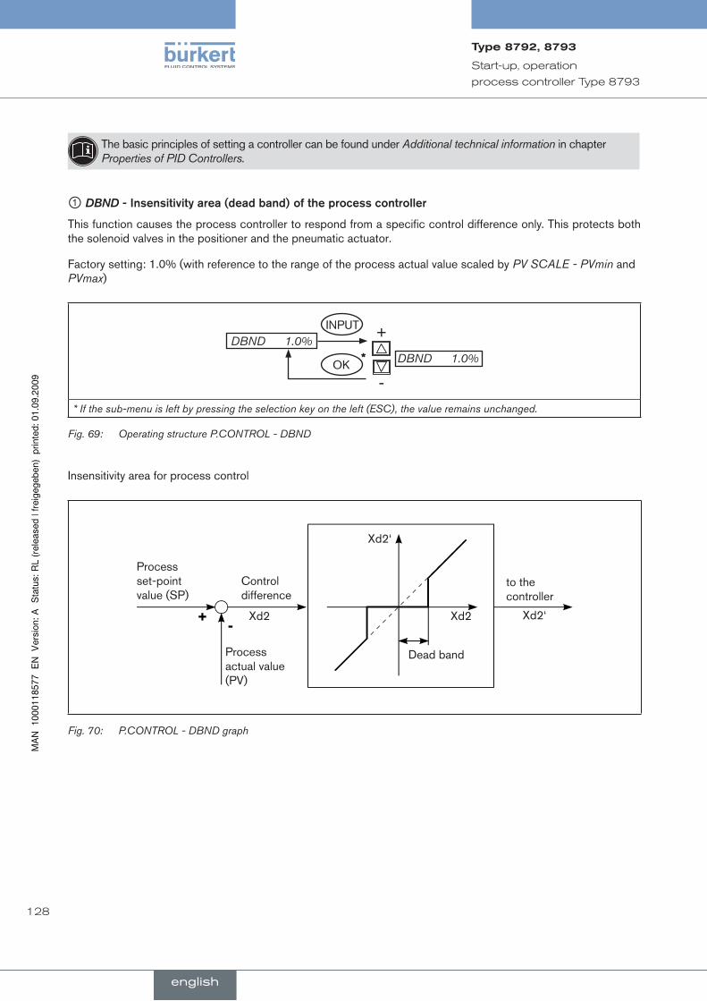
128
Start-up, operation
process controller Type 8793
The basic principles of setting a controller can be found under Additional technical information in chapter Properties of PID Controllers.
① DBND.-.Insensitivity.area.(dead.band).of.the.process.controller
This function causes the process controller to respond from a specific control difference only. This protects both the solenoid valves in the positioner and the pneumatic actuator.
Factory setting: 1.0% (with reference to the range of the process actual value scaled by PV SCALE - PVmin and PVmax)
+
-DBND 1.0%
DBND 1.0%INPUT
OK*
* If the sub-menu is left by pressing the selection key on the left (ESC), the value remains unchanged.
Operating structure P.CONTROL - DBNDFig. 69:
Insensitivity area for process control
Process set-point value (SP)
Control difference
Xd2
Process actual value (PV)
Xd2
Xd2‘
Xd2‘
to the controller
Dead band
P.CONTROL - DBND graphFig. 70:
english
Type8792,8793
english

129
Start-up, operation
process controller Type 8793
② KP.-.Amplification.factor.of.the.process.controller
The amplification factor specifies the P-contribution of the PID controller.
Factory setting: 1.00
+
←
KP 1.00KP 1.00
INPUT
OK* Adjustment range:
0 – 99.99 (% / set unit)
Operating structure P.CONTROL - KPFig. 71:
The KP amplification of the process controller refers to the scaled unit.
③ TN.-.reset.time.of.the.process.controller
Specifies the I-contribution of the PID controller.
Factory setting: 999.9 s
+
←
TN 999.9TN 0.5
INPUT
OK* Adjustment range:
0.5 – 999.9 s
Operating structure P.CONTROL - TNFig. 72:
④ TV.-.hold-back.time.of.the.process.controller
Specifies the D-contribution of the PID controller.
Factory setting: 0.0 s
+
←
TV 0.0TV 0.0
INPUT
OK* Adjustment range:
0 – 999.9 s
Operating structure P.CONTROL - TVFig. 73:
* If the sub-menu is left by pressing the selection key on the left (ESC), the value remains unchanged.
english
Type8792,8793
english
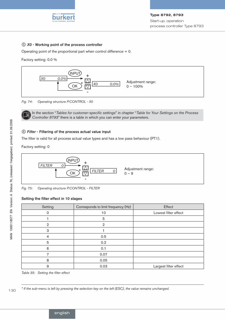
130
Start-up, operation
process controller Type 8793
⑤ X0.-.Working.point.of.the.process.controller
Operating point of the proportional part when control difference = 0.
Factory setting: 0.0 %
+
-X0 0.0%
X0 0.0%INPUT
OK* Adjustment range:
0 – 100%
Operating structure P.CONTROL - X0Fig. 74:
In the section “Tables for customer-specific settings” in chapter “Table for Your Settings on the Process Controller 8793” there is a table in which you can enter your parameters.
⑥ Filter.-.Filtering.of.the.process.actual.value.input
The filter is valid for all process actual value types and has a low pass behaviour (PT1).
Factory setting: 0
+
-FILTER 0
FILTER 0INPUT
OK* Adjustment range:
0 – 9
Operating structure P.CONTROL - FILTERFig. 75:
Setting.the.filter.effect.in.10.stages
Setting Corresponds to limit frequency (Hz) Effect
0 10 Lowest filter effect
1 5
2 2
3 1
4 0.5
5 0.2
6 0.1
7 0.07
8 0.05
9 0.03 Largest filter effect
Setting the filter effectTable 35:
* If the sub-menu is left by pressing the selection key on the left (ESC), the value remains unchanged.
english
Type8792,8793
english
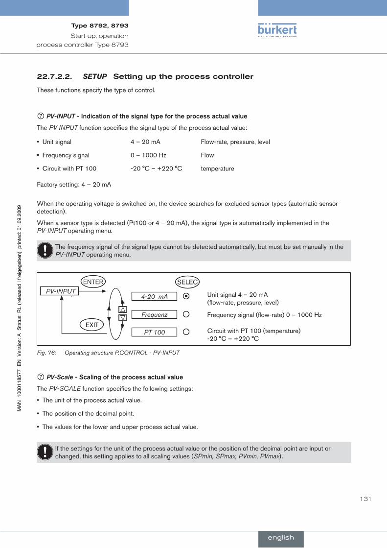
131
Start-up, operation
process controller Type 8793
22.7.2.2. SETUPsettinguptheprocesscontroller
These functions specify the type of control.
⑦ PV-INPUT.-.Indication.of.the.signal.type.for.the.process.actual.value
The PV INPUT function specifies the signal type of the process actual value:
Unit signal 4 – 20 mA Flow-rate, pressure, level•
Frequency signal 0 – 1000 Hz Flow•
Circuit with PT 100 -20 °C – +220 °C temperature•
Factory setting: 4 – 20 mA
When the operating voltage is switched on, the device searches for excluded sensor types (automatic sensor detection).
When a sensor type is detected (Pt100 or 4 – 20 mA), the signal type is automatically implemented in the PV-INPUT operating menu.
The frequency signal of the signal type cannot be detected automatically, but must be set manually in the PV-INPUT operating menu.
PV-INPUT4-20 mA Unit signal 4 – 20 mA
(flow-rate, pressure, level)
Frequenz Frequency signal (flow-rate) 0 – 1000 Hz
PT 100 Circuit with PT 100 (temperature) -20 °C – +220 °C
ENTER SELEC
EXIT
Operating structure P.CONTROL - PV-INPUTFig. 76:
⑦ PV-Scale.-.Scaling.of.the.process.actual.value
The PV-SCALE function specifies the following settings:
The unit of the process actual value.•
The position of the decimal point.•
The values for the lower and upper process actual value.•
If the settings for the unit of the process actual value or the position of the decimal point are input or changed, this setting applies to all scaling values (SPmin, SPmax, PVmin, PVmax).
english
Type8792,8793
english
132
Start-up, operation
process controller Type 8793
Procedure.for.setting.the.scaling.values:
Inputting.the.unit.and.the.position.of.the.decimal.point.for.the.scaling.values.(possible.in.PVmin.only):
Using the arrow keys, select the .→ PV SCALE menu option and confirm by pressing the right selection key (ENTER).
Press the right selection key (INPUT) to switch to the input screen for .→ PVmin.
On the display the field for the unit has a dark background and is therefore marked.
Press the up arrow key (+) to select the unit (bar, mbar, .... °F) for the scaling values. The units indicated here .→depend on the signal type (PV INPUT).
Press the down arrow key (.→ ←) to change the dark highlighted background to the decimal point of the value.
Press the up arrow key (+) to specify the position of the decimal point..→
Inputting.the.scaling.value:
Press the down arrow key (.→ ←) to change the dark highlighted background to the last digit of the value.
Press the up arrow key (+) to specify the value of the individual digit. .→
Press the down arrow key (.→ ←) to switch to the next digit.
When all input values have been specified, confirm the values by pressing the right selection key (OK). .→The menu then jumps back to the selection screen.
⑧a ..PV-SCALE.-.Scaling.the.process.actual.value.for.signal.type.4.–.20.mA (PV-INPUT 4 – 20 mA)
With the PV-SCALE function for signal type 4 – 20 mA the following settings are specified:
The unit of the process actual value.•
The position of the decimal point.•
The values for the lower and upper process actual value are assigned to the respective current value of the unit • signal.
If the settings for the unit of the process actual value or the position of the decimal point are input or changed, this setting applies to all scaling values (PVmin, PVmax, SPmin, SPmax).
english
Type8792,8793
english
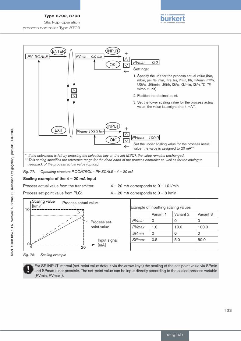
133
Start-up, operation
process controller Type 8793
+
←
PVmin 0.0
PVmin 0.0 barINPUT
OK*
Settings:
1. Specify the unit for the process actual value (bar, mbar, psi, %, mm, litre, l/s, l/min, l/h, m³/min, m³/h, UG/s, UG/min, UG/h, IG/s, IG/min, IG/h, °C, °F, without unit).
2. Position the decimal point.
3. Set the lower scaling value for the process actual value; the value is assigned to 4 mA**.
PV SCALE
+
←
PVmax 100.0
PVmax 100.0 barINPUT
OK*
Set the upper scaling value for the process actual value; the value is assigned to 20 mA**
ENTER
EXIT
* If the sub-menu is left by pressing the selection key on the left (ESC), the value remains unchanged. ** This setting specifies the reference range for the dead band of the process controller as well as for the analogue
feedback of the process actual value (option).
Operating structure P.CONTROL - PV-SCALE - 4 – 20 mAFig. 77:
Scaling.example.of.the.4.–.20.mA.input
Process actual value from the transmitter: 4 – 20 mA corresponds to 0 – 10 l/min
Process set-point value from PLC: 4 – 20 mA corresponds to 0 – 8 l/min
Scaling value [l/min]
Input signal [mA]
Process set-point value
Process actual value
4 0
10
20
Example of inputting scaling values
Variant 1 Variant 2 Variant 3
PVmin 0 0 0
PVmax 1.0 10.0 100.0
SPmin 0 0 0
SPmax 0.8 8.0 80.0
Scaling exampleFig. 78:
For SP INPUT internal (set-point value default via the arrow keys) the scaling of the set-point value via SPmin and SPmax is not possible. The set-point value can be input directly according to the scaled process variable (PVmin, PVmax ).
english
Type8792,8793
english

134
Start-up, operation
process controller Type 8793
⑧b .PV-SCALE.-.PV-SCAlE.-.2.-.Scaling.of.the.process.actual.value.for.frequency.input.signal.type..(PV.InPuT.frequency)
The PV-SCALE function specifies the following settings for frequency input signal type:
The unit of the process actual value.•
The position of the decimal point.•
The values for the lower and upper process actual value.•
The K-factor.•
If the settings for the unit of the process actual value or the position of the decimal point are input or changed, this setting applies to all scaling values (PVmin, PVmax, SPmin, SPmax).
+
←
PVmin 0.0 PVmin 0.0 l/s
*
PV SCALE
+
←
PVmax 100.0 PVmax 100.0 l/s
*
K-Factor VALUE 1
TEACH IN
ENTER
EXIT
EXIT
OK
OK
INPUT
INPUT
ENTER
* If the sub-menu is left by pressing the selection key on the left (ESC), the value remains unchanged.
Operating structure P.CONTROL - PV-SCALE - FrequencyFig. 79:
english
Type8792,8793
english
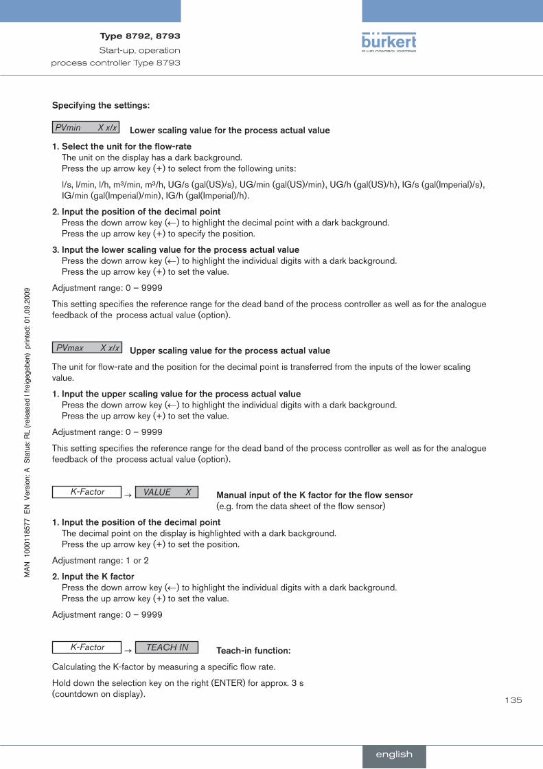
135
Start-up, operation
process controller Type 8793
Specifying.the.settings:
PVmin X x/x lower.scaling.value.for.the.process.actual.value
1...Select.the.unit.for.the.flow-rate The unit on the display has a dark background. Press the up arrow key (+) to select from the following units:
l/s, l/min, l/h, m³/min, m³/h, UG/s (gal(US)/s), UG/min (gal(US)/min), UG/h (gal(US)/h), IG/s (gal(Imperial)/s), IG/min (gal(Imperial)/min), IG/h (gal(Imperial)/h).
2...Input.the.position.of.the.decimal.point Press the down arrow key (←) to highlight the decimal point with a dark background. Press the up arrow key (+) to specify the position.
3...Input.the.lower.scaling.value.for.the.process.actual.value Press the down arrow key (←) to highlight the individual digits with a dark background. Press the up arrow key (+) to set the value.
Adjustment range: 0 – 9999
This setting specifies the reference range for the dead band of the process controller as well as for the analogue feedback of the process actual value (option).
PVmax X x/x upper.scaling.value.for.the.process.actual.value
The unit for flow-rate and the position for the decimal point is transferred from the inputs of the lower scaling value.
1...Input.the.upper.scaling.value.for.the.process.actual.value Press the down arrow key (←) to highlight the individual digits with a dark background. Press the up arrow key (+) to set the value.
Adjustment range: 0 – 9999
This setting specifies the reference range for the dead band of the process controller as well as for the analogue feedback of the process actual value (option).
K-Factor → VALUE X Manual.input.of.the.K.factor.for.the.flow.sensor (e.g. from the data sheet of the flow sensor)
1...Input.the.position.of.the.decimal.point The decimal point on the display is highlighted with a dark background. Press the up arrow key (+) to set the position.
Adjustment range: 1 or 2
2...Input.the.K.factor Press the down arrow key (←) to highlight the individual digits with a dark background. Press the up arrow key (+) to set the value.
Adjustment range: 0 – 9999
K-Factor → TEACH IN Teach-in.function:
Calculating the K-factor by measuring a specific flow rate.
Hold down the selection key on the right (ENTER) for approx. 3 s (countdown on display).
english
Type8792,8793
english
136
Start-up, operation
process controller Type 8793
When this menu is entered, the valve is closed in order to have a defined initial state for implementation of the Teach-in function.
Starting.the.measurement Press the selection key on the right (START) to start the measurement (the message “Teach-in at work” is dis-played briefly). The valve is opened and the container is filled (“→ fill ..” is indicated on the display).
Ending.the.measurement Press the selection key on the right (STOP) to end the measurement and to display the input screen for the volume.
Input.the.position.of.the.decimal.point.The decimal point on the display is highlighted with a dark background. Press the up arrow key (+) to specify the position.
Input.the.measured.volume Press the down arrow key (←) to highlight the individual digits with a dark background. Press the up arrow key (+) to set the value.
Adjustment range: 0 – 9999
english
Type8792,8793
english

137
Start-up, operation
process controller Type 8793
⑧c .PV-SCALE - Scaling of the process.actual.value for selection of the PT 100 input (PV INPUT PT 100)
The PV-SCALE function specifies the following settings for the PT 100 signal type:
The unit of the process actual value.•
Position of the decimal point.•
The values for the lower and upper process actual value.•
If the settings for the unit of the process actual value or the position of the decimal point are input or changed, this setting applies to all scaling values (PVmin, PVmax, SPmin, SPmax).
+
←
PVmin 0 PVmin 0 *C
*
PV SCALE
+
←
PVmax 100.0 PVmax 100.0 *C
*
ENTER
EXIT
OK
OK
INPUT
INPUT
* If the sub-menu is left by pressing the selection key on the left (ESC), the value remains unchanged.
Operating structure P-CONTROL-PV-SCALE - PT100Fig. 80:
Specifying.the.settings:
PVmin X *X lower.scaling.value.for.the.process.actual.value
1..Select.the.unit.for.the.temperature The unit on the display is highlighted with a dark background. Press the up arrow key (+) to select from the fol-lowing units:
°C or °F.
2..Input.the.position.of.the.decimal.point Press the down arrow key (←) to highlight the decimal point with a dark background. Press the up arrow key (+) to specify the position.
Adjustment range: 1 or 2
3..Input.the.lower.scaling.value.for.the.process.actual.value.Press the down arrow key (←) to highlight the individual digits with a dark background. Press the up arrow key (+) to set the value.
Adjustment range: -200 – 800
Measurement range of the PT 100: -20 °C – 220 °C or -4 °F – 428 °F
This setting specifies the reference range for the dead band of the process controller as well as for the analogue feedback of the process actual value (option)
english
Type8792,8793
english
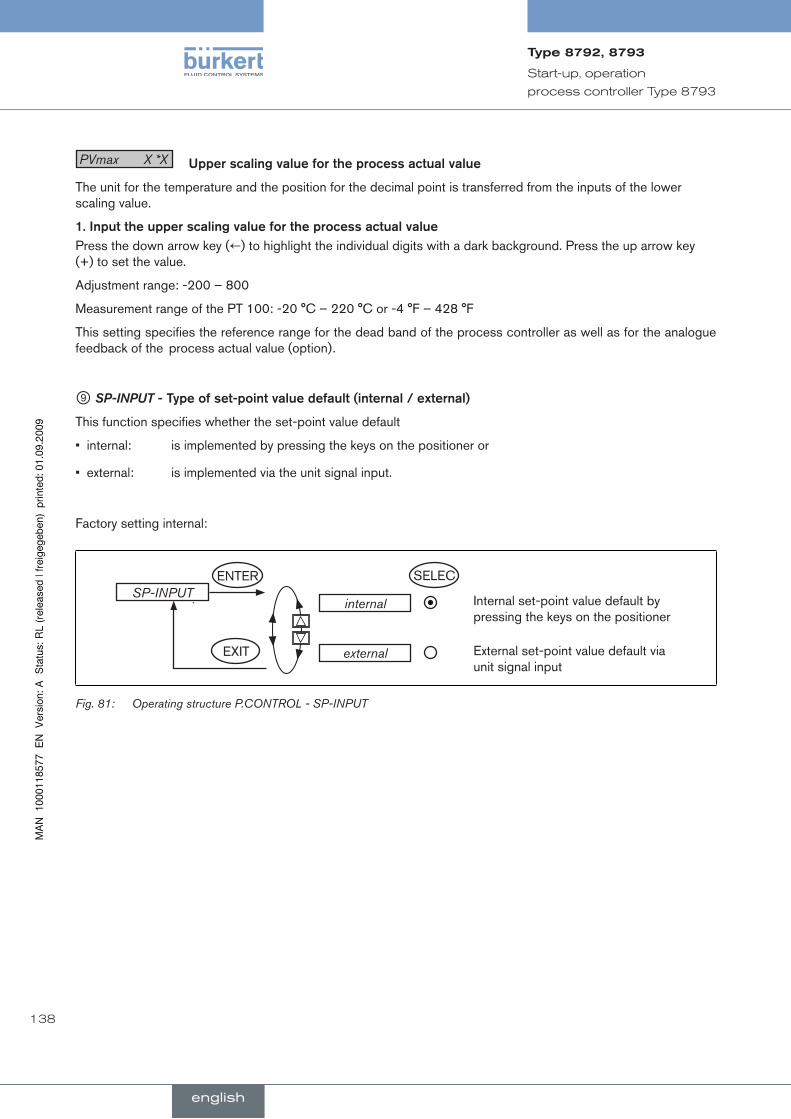
138
Start-up, operation
process controller Type 8793
PVmax X *X upper.scaling.value.for.the.process.actual.value
The unit for the temperature and the position for the decimal point is transferred from the inputs of the lower scaling value.
1..Input.the.upper.scaling.value.for.the.process.actual.value Press the down arrow key (←) to highlight the individual digits with a dark background. Press the up arrow key (+) to set the value.
Adjustment range: -200 – 800
Measurement range of the PT 100: -20 °C – 220 °C or -4 °F – 428 °F
This setting specifies the reference range for the dead band of the process controller as well as for the analogue feedback of the process actual value (option).
⑨ SP-INPUT -.Type.of.set-point.value.default.(internal./.external)
This function specifies whether the set-point value default
internal: is implemented by pressing the keys on the positioner or •
external: is implemented via the unit signal input.•
Factory setting internal:
SP-INPUTinternal Internal set-point value default by
pressing the keys on the positioner
external External set-point value default via unit signal input
ENTER
EXIT
SELEC
Operating structure P.CONTROL - SP-INPUTFig. 81:
english
Type8792,8793
english

139
Start-up, operation
process controller Type 8793
⑩ SP-SCALE -.Scaling.of.the.process.set-point.value
This function is indicated in the selection menu only if the external set-point value default (external) has been selected in the SP INPUT menu option.
The SP-SCALE function assigns the values for the lower and upper process set-point value to the particular current or voltage value of the unit signal.
+
←
SPmin 0.0
SPmin 0.0 barINPUT
OK*
Set the lower scaling value for the process set-point value. The value is assigned to the lowest current or voltage value of the unit signal.
SP SCALEENTER
EXIT +
←
SPmax 100.0
SPmax 100.0 barINPUT
OK*
Set the upper scaling value for the process set-point value. The value is assigned to the largest current or voltage value of the unit signal.
* If the sub-menu is left by pressing the selection key on the left (ESC), the value remains unchanged.
Operating structure P.CONTROL - SP-SCALEFig. 82:
Procedure.for.setting.the.scaling.values.(in.the.example.of.the.lower.scaling.value.SPmin):
Press the right selection key (INPUT) to select the input screen for .→ SPmin.
On the display the last digit of the value is highlighted with a dark background.
Press the up arrow key (+) to specify the value of the individual digit. .→
Press the down arrow key (.→ ←) to switch to the next digit.
When all input values have been specified, confirm the values by pressing the right selection key (OK). .→The menu then jumps back to the selection screen.
english
Type8792,8793
english

140
Start-up, operation
process controller Type 8793
⑪ P.CO INIT.-.Setting.the.smooth.switchover.between.MAnuAl.and.AuTOMATIC
The P.CO INIT function enables a smooth switchover between the MANUAL and AUTOMATIC operating states.
Factory setting: bumpless
P.CO-INITbumpless Gentle switchover activated
standard Gentle switchover deactivated
ENTER
EXIT
SELEC
Operating structure P.CO INITFig. 83:
english
Type8792,8793
english

141
Start-up, operation
process controller Type 8793
22.7.3. P.Q’LINlinearizationoftheprocesscharacteristic
This function automatically linearises the process characteristic.
When the P.CONTROL function is activated, the P.Q’LIN functions required for process control are copied into the main menu. This function starts the program which automatically determines the nodes for a correction characteristic.
Start the routine to linearise the process characteristic by selecting the .→ P.Q’LIN menu option in the main menu and press the selection key on the right (RUN) for approx. 3 seconds (countdown).
The program goes through the valve stroke in 20 steps from 0 to 100 % and measures the associated process variable. The value pairs of the correction characteristic are placed as a freely programmable characteristic under the CHARACT / FREE menu option and can be viewed under this menu option.
If the CHARACT menu option under the ADDFUNCTION menu option was not transferred into the main menu, the transfer occurs automatically when the P.Q'LIN function is implemented. At the same time the CHARACT / FREE menu option is activated.
Displays.on.the.panel.during.selection.and.implementation.of.the.routine
Display Description
Q.LIN #0 CMD=0%
Q.LIN #1 CMD=10%
:
Q.LIN #10 CMD=100%
Q.LIN ready
or
Q.LIN err/break
Display of the node which is just being started (progress is indicated by a bar running along the upper edge of the display)
Display at the end of the routine
Display if an error occurs
Display for P,Q‘LIN - Linearization of the process characteristicTable 36:
english
Type8792,8793
english
142
Start-up, operation
process controller Type 8793
P.TUNE22.7.4. self-optimizationoftheprocesscontroller
(processtune)
The control system of the type 8793 has an integrated PID process controller. When an appropriate sensor is connected, any process variable such as flow rate, temperature, pressure, etc. can be controlled.
To obtain a good control performance, the structure and parameterization of the controller must be adjusted to the properties of the process (controlled system). This task requires experience in control technology as well as in measurement aids and is time-consuming. Therefore, the control system of type 8793 features the P.TUNE self-optimization function which determines the structure and parameters of the process controller at the press of a button. The determined PID parameters can be seen via the operating menu and modified at will.
Operatingmode22.7.4.1.
When the P.TUNE function runs, the process is automatically identified. To do this, the process is initiated with a defined disturbance variable. Characteristic process parameters are derived from the response signal and are the basis for determining the structure and parameters of the process controller.
If the P.TUNE self-optimization is used, optimum results are obtained based on the following requirements:
Stable or stationary conditions with reference to the process actual value PV when • P.TUNE starts.
Implementation of the • P.TUNE in the operating point or in the operating range of the process control.
Operation22.7.4.2.
The P.TUNE function can be run when the process controller is either in automatic or manual mode.
When P.TUNE ends, the control system is in the operating mode which was set previously.
The procedures described in the following sections a) and b) are not mandatory requirements for running the P.TUNE function. However, they increase the quality of the result.
a) P.TUNE in manual mode
The operator is on the process operating level.
Press the arrow keys to display the process value PV..→
Switch the control system to manual mode by pressing the right key HAND..→
The requirements mentioned in the previous chapter to obtain optimum results are set in the following Way:
Manually open or close the control valve by pressing the OPEN / CLOSE arrow keys and move the process .→value up to the required operating point or operating range.
As soon as the obtained setting is temporally constant, start the P.TUNE function (see chapter 22.7.4.3. Start .→the P.TUNE function).
english
Type8792,8793
english

143
Start-up, operation
process controller Type 8793
b) P.TUNE in automatic mode
The operator is on the process operating level.
Specify a process set-point value SP via the keyboard or via the analog set-point value input. .→In.doing.so,.observe.the.setting.for.the.internal.or.external.set-point.value.default! The selected set-point value SP should be near the future operating point.
According to the set-point value default the process variable PV changes on the basis of the PID parameters preset at the factory.
To satisfy the requirements mentioned in the chapter for obtaining optimum results, wait until the .→ PV reaches a stable state.
When PV is oscillating permanently, the preset value KP of the process controller should be reduced in the P.CONTROL → PARAMETER menu.
.→
To observe PV, you can select the graphical display SP/PV(t) by pressing the arrow keys.
As soon as the.→ PV is temporally constant, start the P.TUNE function (see the following chapter).
startthe22.7.4.3. P.TUNE fundtion
WarnInG!
risk.of.injury.due.to.uncontrolled.process!
While the P.TUNE function is running, the control valve automatically changes the momentary degree of opening and engages in the current process.
Using suitable measures, prevent the permitted process limits from being exceeded. • For example by: - an automatic emergency shutdown - stopping the P.TUNE function by pressing the STOP key (press left or right key).
The operator is on the configuration and parameterization level.
In the main menu select the .→ P.TUNE function by pressing the arrow keys.
Hold down the right .→ RUN key for approx. 3 s (countdown on display). The P.TUNE self-optimization function runs according to the diagram indicated in the following Table 37:. At the end the TUNE ready message is indicated.
Press any key to return to the main menu..→
To stop the P.TUNE self-optimization function, press the left or right key STOP key.
english
Type8792,8793
english
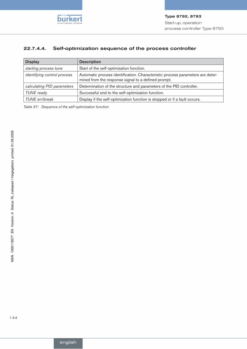
144
Start-up, operation
process controller Type 8793
self-optimizationsequenceoftheprocesscontroller22.7.4.4.
Display Description
starting process tune Start of the self-optimization function.
identifying control process Automatic process identification. Characteristic process parameters are deter-mined from the response signal to a defined prompt.
calculating PID parameters Determination of the structure and parameters of the PID controller.
TUNE ready Successful end to the self-optimization function.
TUNE err/break Display if the self-optimization function is stopped or if a fault occurs.
Sequence of the self-optimization functionTable 37:
english
Type8792,8793
english
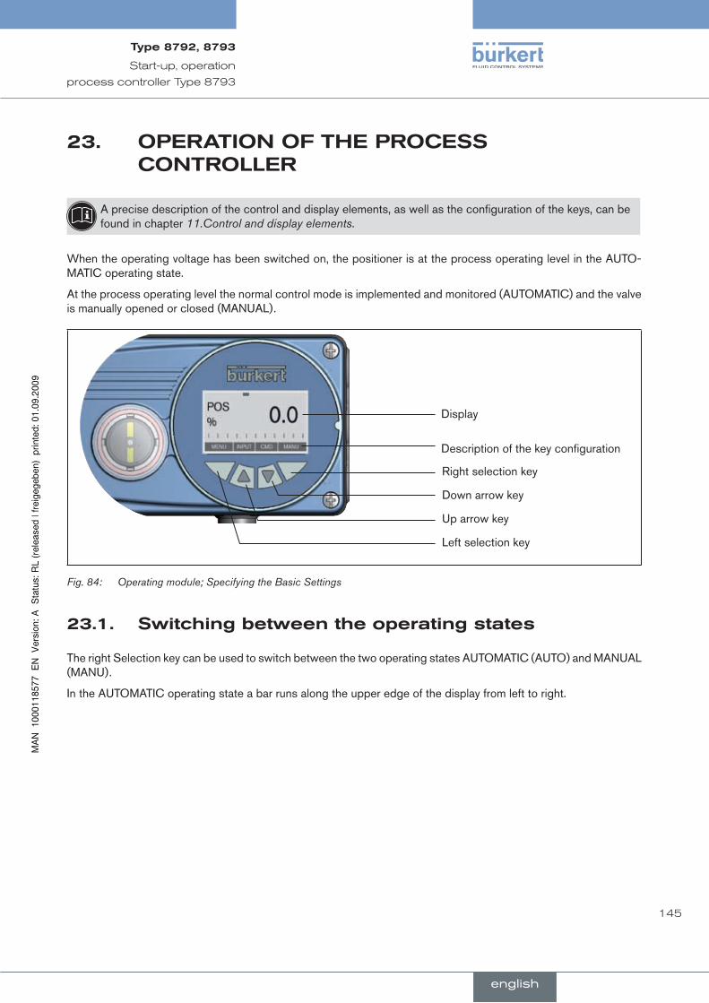
145
Start-up, operation
process controller Type 8793
OperaTiOnOfTheprOcess23.cOnTrOller
A precise description of the control and display elements, as well as the configuration of the keys, can be found in chapter 11.Control and display elements.
When the operating voltage has been switched on, the positioner is at the process operating level in the AUTO-MATIC operating state.
At the process operating level the normal control mode is implemented and monitored (AUTOMATIC) and the valve is manually opened or closed (MANUAL).
Display
Description of the key configuration
Right selection key
Down arrow key
Up arrow key
Left selection key
Operating module; Specifying the Basic SettingsFig. 84:
switchingbetweentheoperatingstates23.1.
The right Selection key can be used to switch between the two operating states AUTOMATIC (AUTO) and MANUAL (MANU).
In the AUTOMATIC operating state a bar runs along the upper edge of the display from left to right.
english
Type8792,8793
english

146
Start-up, operation
process controller Type 8793
switchingbetweentheoperatinglevels23.2.
Process.operating.level.->.Configuration.level
To switch to the configuration level in the MANUAL or AUTOMATIC operating state
hold down the left selection key (MENU) for approx. 3 seconds (countdown: two bars converge on the .→display).
At the Configuration level the operating parameters can be input or changed, auxiliary functions supplemented or the automatic adjustment (X.TUNE) of the controller started.
A precise description of the individual functions can be found in chapter Configuring the auxiliary functions.
Configuration.level.->.Process.operating.level
Press the left selection key (EXIT) to switch from the Configuration level to the Process operating level. In doing so, the operating state which was selected before the switchover (AUTOMATIC or MANUAL) is set.
auTOMaTicoperatingstate23.3.
Bar running from left to right along the upper edge of the display.
Normal control mode is implemented and monitored in AUTOMATIC operating state.
Meaningofthekeys23.3.1.
key Configuration* Description
Left selection key MENU Switch to the Configuration level (press for approx. 3 s)
Right selection key MANU Switch between the AUTOMATIC (AUTO) or MANUAL (MANU) operating modes
Up arrow key SP
SP/PV graphic
POS
CMD
TEMP
PV
Switch between the individual displays
Down arrow key CMD
TEMP
PV
SP
SP/PV graphic
POS
* Displayed only when P.CONTROL auxiliary function activated
AUTOMATIC operating state; Meaning of the keys; Process controller Type 8793Table 38:
english
Type8792,8793
english

147
Start-up, operation
process controller Type 8793
informationonthedisplay23.3.2.
The following variables are indicated on the display for the process controller and it is possible to switch between them with the arrow keys:
representation.of.value
Value.range./.unit Description
POS XXX 0 – 100 % Display of actual position of the valve actuator
CMD XXX 0 – 100 % Display of nominal position of the valve actuator
TEMP XXX -100 – 150 °C Internal temperature in the housing of the positioner
PV XXX Depending on the signal type Process actual value
SP XXX Depending on the signal type Process set-point value
Display; process controller Type 8793Table 39:
Operatingstructure23.3.3.
Configuration
Menu option
EXIT
Display
(no operator action)
Switch between the displays*
POS PV CMD SP TEMP
EXIT
MENU
AUTOMATIC operating state
MANUAL operating state
MANUAUTO
active**SP
Set process set-point value
INPUT
OK
* Displayed only when P.CONTROL auxiliary function activated.
** only active if the internal set-point value default (P.CONTROL / SETUP / SP INPUT / internal) has been selected.
Operating structure AUTOMATIC; process controller Type 8793Fig. 85:
english
Type8792,8793
english
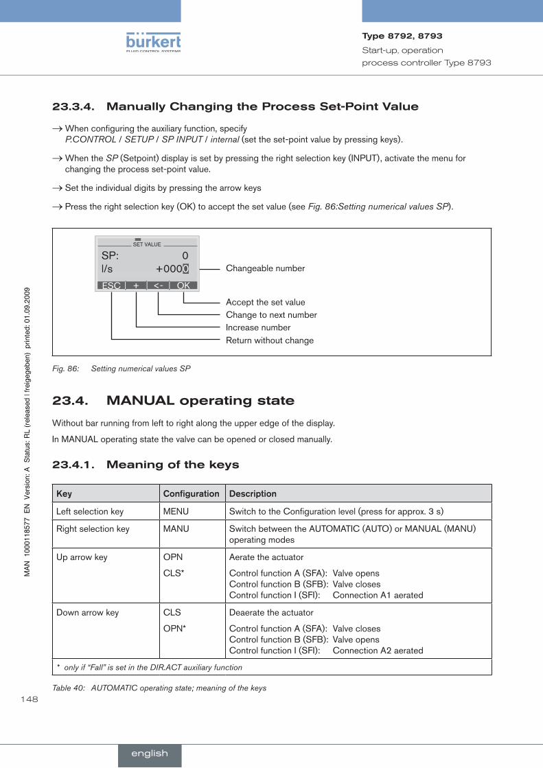
148
Start-up, operation
process controller Type 8793
Manuallychangingtheprocessset-pointvalue23.3.4.
When configuring the auxiliary function, specify .→P.CONTROL / SETUP / SP INPUT / internal (set the set-point value by pressing keys).
When the .→ SP (Setpoint) display is set by pressing the right selection key (INPUT), activate the menu for changing the process set-point value.
Set the individual digits by pressing the arrow keys .→
Press the right selection key (OK) to accept the set value (see .→ Fig. 86:Setting numerical values SP).
Accept the set value
Return without change
ESC OK+ <-
SET VALUE
SP: 0 l/s +0000
Change to next numberIncrease number
Changeable number
Fig. 86: Setting numerical values SP
Manualoperatingstate23.4.
Without bar running from left to right along the upper edge of the display.
In MANUAL operating state the valve can be opened or closed manually.
Meaningofthekeys23.4.1.
Key Configuration Description
Left selection key MENU Switch to the Configuration level (press for approx. 3 s)
Right selection key MANU Switch between the AUTOMATIC (AUTO) or MANUAL (MANU) operating modes
Up arrow key OPN
CLS*
Aerate the actuator
Control function A (SFA): Valve opens Control function B (SFB): Valve closes Control function I (SFI): Connection A1 aerated
Down arrow key CLS
OPN*
Deaerate the actuator
Control function A (SFA): Valve closes Control function B (SFB): Valve opens Control function I (SFI): Connection A2 aerated
* only if “Fall” is set in the DIR.ACT auxiliary function
AUTOMATIC operating state; meaning of the keysTable 40:
english
Type8792,8793
english

149
Start-up, operation
process controller Type 8793
SFA: Actuator closes by spring force
SFB: Actuator opens by spring force
SFI: Actuator double-acting
informationonthedisplay23.4.2.
After switching to the MANUAL operating state, the display automatically jumps to the actual position (POS) of the valve actuator.
Operatingstructure23.4.3.
Configuration
Menu option
EXIT
Display
(no operator action)Valve open
EXIT MENU
AUTOMATIC operating state
MANUAL operating state MANUAUTO
Release key
Release key
Valve closed
Operating structure MANUAL Fig. 87:
english
Type8792,8793
english
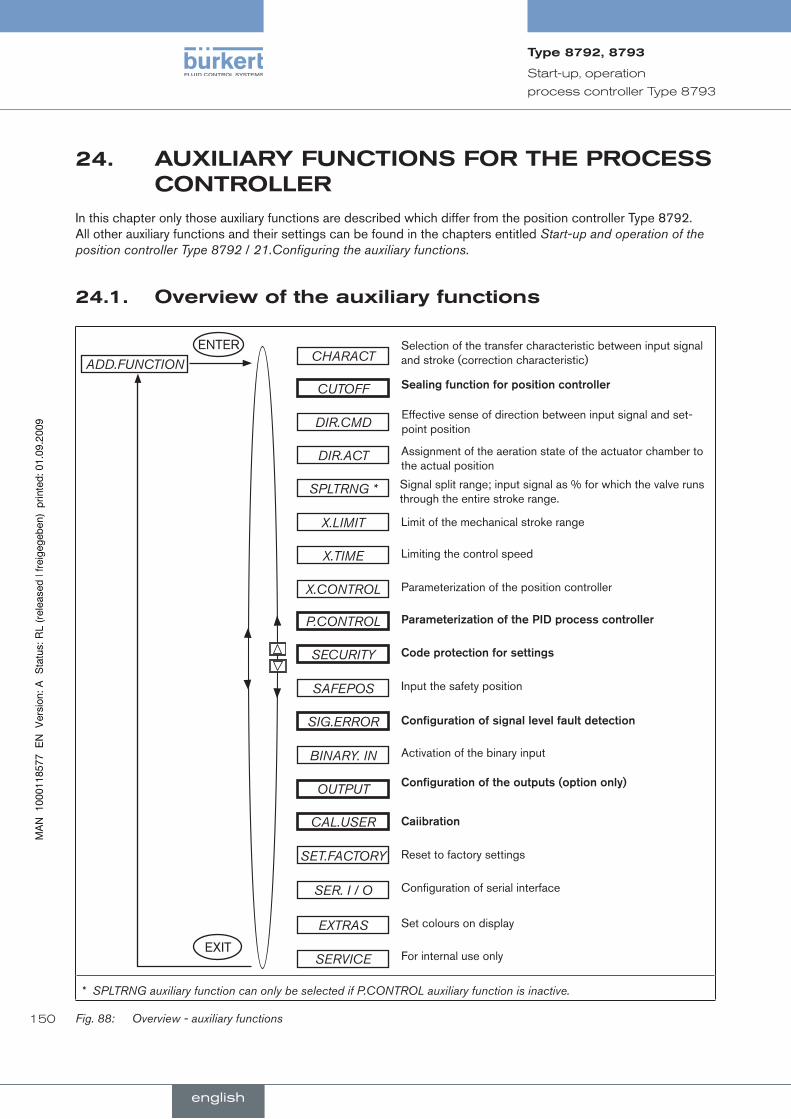
150
Start-up, operation
process controller Type 8793
24. auxiliaryfuncTiOnsfOrTheprOcesscOnTrOller
In this chapter only those auxiliary functions are described which differ from the position controller Type 8792. All other auxiliary functions and their settings can be found in the chapters entitled Start-up and operation of the position controller Type 8792 / 21.Configuring the auxiliary functions.
Overviewoftheauxiliaryfunctions24.1.
ENTERCHARACT
ADD.FUNCTIONSelection of the transfer characteristic between input signal and stroke (correction characteristic)
CUTOFF Sealing.function.for.position.controller.
DIR.CMDEffective sense of direction between input signal and set-point position
DIR.ACT Assignment of the aeration state of the actuator chamber to the actual position
SPLTRNG * Signal split range; input signal as % for which the valve runs through the entire stroke range.
X.LIMIT Limit of the mechanical stroke range
X.TIME Limiting the control speed
X.CONTROL
P.CONTROL
Parameterization of the position controller
Parameterization.of.the.PID.process.controller
SECURITY Code.protection.for.settings
SAFEPOS Input the safety position
SIG.ERROR Configuration.of.signal.level.fault.detection
BINARY. IN Activation of the binary input
OUTPUT Configuration.of.the.outputs.(option.only)
CAL.USER Caiibration
SET.FACTORY Reset to factory settings
SER. I / O Configuration of serial interface
EXTRAS Set colours on display
SERVICE For internal use onlyEXIT
* SPLTRNG auxiliary function can only be selected if P.CONTROL auxiliary function is inactive.
Fig. 88: Overview - auxiliary functions
english
Type8792,8793
english

151
Start-up, operation
process controller Type 8793
If the P.CONTROL auxiliary function is active for the process controller Type 8793, the following auxiliary func-tions differ from those described for the position controller Type 8792 (highlighted in Fig. 88:):
CUTOFF•
P.CONTROL•
SECURITY•
SIG.ERROR•
OUTPUT•
CAL. USER•
includingauxiliaryfunctionsinthemainmenu24.1.1.
In the main menu press the arrow keys to select the .→ ADD.FUNCTION menu option and press the selection key on the right (ENTER) to enter the submenu.
Press the arrow keys to select the required auxiliary function. .→
Press the selection key on the right (ENTER) to mark the auxiliary function with a cross (x). .→
Press the selection key on the left (EXIT) to transfer the marked functions into the main menu. .→
In the main menu now input the parameters for the auxiliary functions..→
removingauxiliaryfunctionsfromthemainmenu24.1.2.
If a function is removed from the main menu, the settings implemented previously under this function become invalid again.
In the main menu press the arrow keys to select the .→ ADD.FUNCTION menu option and press the selection key on the right (ENTER) to enter the submenu.
Using the arrow keys, select an auxiliary function indicated with a cross (x)..→
Press the selection key on the right (ENTER) to remove the cross (x). .→
After pressing the selection key on the left (EXIT), the auxiliary function is deactivated and removed from the .→main menu.
How to operate the auxiliary functions is described exactly in the chapter entitled Start-up and operation of the position controller Type 8792 / 21.Configuring the auxiliary functions.
english
Type8792,8793
english

152
Start-up, operation
process controller Type 8793
24.2. CUTOFF sealingfunctionforthepositioncontrollerType8793
This function causes the valve to be sealed outside the control area.
This is where you input the limits for the position set-point value (CMD) as a percentage or for the process set-point value (SP) as a percentage of the scaling range, from which the actuator is fully deaerated or aerated.
Control mode opens or resumes at a hysteresis of 1%.
If the process valve is in the sealing area, the message “CUTOFF ACTIVE” is indicated on the display.
Factory setting: Min= 0%; Max = 100%; CUT type = Type PCO
CUTOFF Min 0 %
Max 100 %
EXIT
INPUT+
-Min 0 %OK
INPUT+
-Max 100 %OK
*
*
Sealing threshold Deaeration (0 = not active)
Adjustment range: 0 – 25 %
Sealing threshold Aeration (100 = not active)
Adjustment range: 75 – 100%
CUT typeType PCO Select process
set-point value
EXIT Type XCOSelect position set-point value
ENTER
ENTER
SELEC
* If the sub-menu is left by pressing the selection key on the left (ESC), the value remains unchanged.
Operating structure CUTOFF, process controller type Type 8793Fig. 89:
Changed values are not transferred into the memory (EEPROM) until the main menu (MAIN) is left.
english
Type8792,8793
english
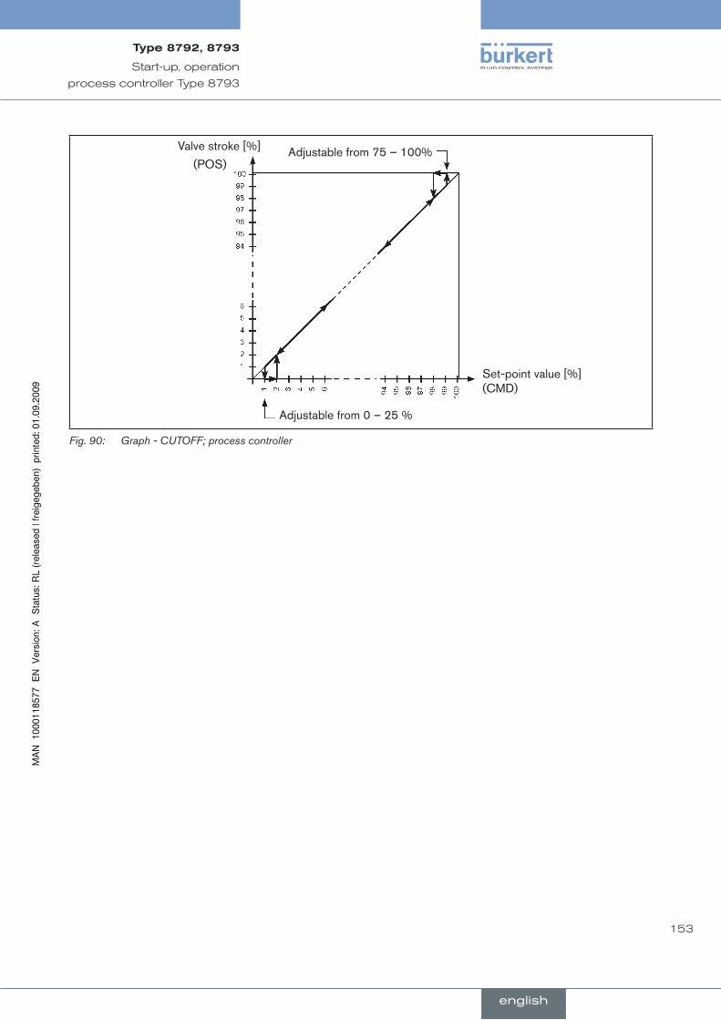
153
Start-up, operation
process controller Type 8793
Valve stroke [%] Adjustable from 75 – 100%
Set-point value [%](CMD)
Adjustable from 0 – 25 %
(POS)
Graph - CUTOFF; process controllerFig. 90:
english
Type8792,8793
english

154
Start-up, operation
process controller Type 8793
24.3. SECURITY codeprotectionforthesettings
Use the SECURITY function to prevent the positioner or individual functions from being accessed unintentionally.
Factory setting: Access Code: 0000
If the code protection is activated, the code (set access code or master code) must be input whenever operator action is disabled.
All operator actions can be implemented with the non-changeable master code. This 4-digit master code can be found in the appendix of these operating instructions in the chapter entitled “Master code”.
SECURITY
CODE
EXIT
ENTER
OK
SELEC
INPUT
ESC OK+ <-
MAIN
MANU/AUTO
ADDFUNCT
X.TUNE
P.Q‘LIN
SET VALUE
Access Code: 1 0000
①
②③④⑤⑥
Operating structure SECURITY; process controllerFig. 91:
①Input screen for inputting or changing the access code (for description of input see below)
②Blocking access to the configuration level
③Blocking switchover between the MANUAL / AUTOMATIC (MANU/AUTO) operating states
④Blocking the input of auxiliary function
⑤Blocking the activation of self-parameterization (Autotune)
⑥Blocking the activation of the linearization of the process characteristic
Inputting.the.access.code:
To access the input screen with marked selection menu CODE, press the selection key on the right (INPUT)..→
english
Type8792,8793
english

155
Start-up, operation
process controller Type 8793
ESC OK+ <-
SET VALUE
Access Code: 1 0000
The four-digit code can be changed via the arrow keys.
Down arrow key (←) Select the individual digits. Up arrow key (+) Change the selected digit.
Left selection button (ESC) Leave the input screen without making a change.
Right selection button (OK) Leave the input screen saving the input or making a change.
english
Type8792,8793
english
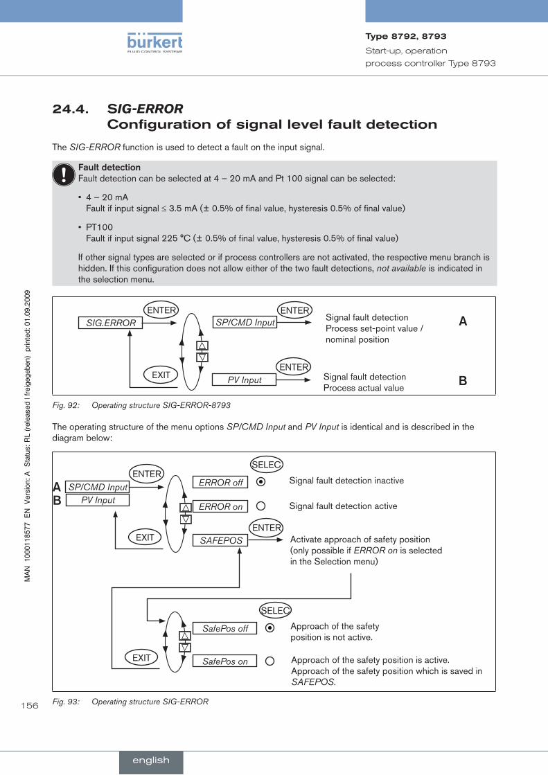
156
Start-up, operation
process controller Type 8793
24.4. sIG-ERROR configurationofsignallevelfaultdetection
The SIG-ERROR function is used to detect a fault on the input signal.
Fault.detection.Fault detection can be selected at 4 – 20 mA and Pt 100 signal can be selected:
4 – 20 mA • Fault if input signal ≤ 3.5 mA (± 0.5% of final value, hysteresis 0.5% of final value)
PT100 • Fault if input signal 225 °C (± 0.5% of final value, hysteresis 0.5% of final value)
If other signal types are selected or if process controllers are not activated, the respective menu branch is hidden. If this configuration does not allow either of the two fault detections, not available is indicated in the selection menu.
SIG.ERROR SP/CMD Input
PV Input
Signal fault detection Process set-point value / nominal position
Signal fault detection Process actual value
ENTER
ENTERENTER
EXIT
A
B
Operating structure SIG-ERROR-8793Fig. 92:
The operating structure of the menu options SP/CMD Input and PV Input is identical and is described in the diagram below:
AB
SELEC
ERROR off
EXIT SAFEPOS
Signal fault detection inactive
Activate approach of safety position (only possible if ERROR on is selected in the Selection menu)
SP/CMD Input
ERROR on Signal fault detection active
SELEC
SafePos off Approach of the safety position is not active.
SafePos on Approach of the safety position is active. Approach of the safety position which is saved in SAFEPOS.
EXIT
ENTER
ENTER
PV Input
Operating structure SIG-ERRORFig. 93:
english
Type8792,8793
english
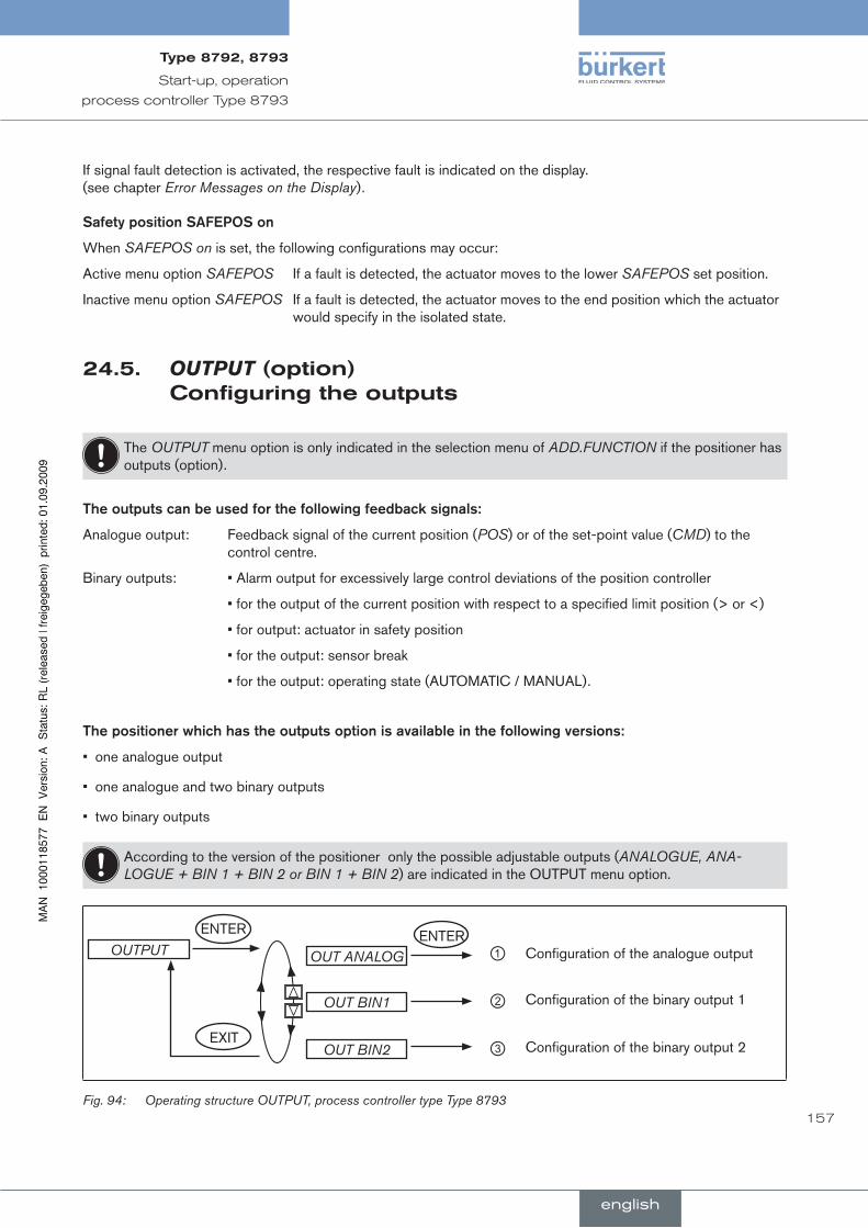
157
Start-up, operation
process controller Type 8793
If signal fault detection is activated, the respective fault is indicated on the display. (see chapter Error Messages on the Display).
Safety.position.SAFEPOS.on
When SAFEPOS on is set, the following configurations may occur:
Active menu option SAFEPOS If a fault is detected, the actuator moves to the lower SAFEPOS set position.
Inactive menu option SAFEPOS If a fault is detected, the actuator moves to the end position which the actuator would specify in the isolated state.
24.5. OUTPUT(option) configuringtheoutputs
The OUTPUT menu option is only indicated in the selection menu of ADD.FUNCTION if the positioner has outputs (option).
The.outputs.can.be.used.for.the.following.feedback.signals:
Analogue output: Feedback signal of the current position (POS) or of the set-point value (CMD) to the control centre.
Binary outputs: • Alarm output for excessively large control deviations of the position controller
• for the output of the current position with respect to a specified limit position (> or <)
• for output: actuator in safety position
• for the output: sensor break
• for the output: operating state (AUTOMATIC / MANUAL).
The.positioner.which.has.the.outputs.option.is.available.in.the.following.versions:
one analogue output•
one analogue and two binary outputs•
two binary outputs•
According to the version of the positioner only the possible adjustable outputs (ANALOGUE, ANA-LOGUE + BIN 1 + BIN 2 or BIN 1 + BIN 2) are indicated in the OUTPUT menu option.
OUTPUT OUT ANALOG
OUT BIN2EXIT
ENTER ENTERConfiguration of the analogue output
OUT BIN1 Configuration of the binary output 1
Configuration of the binary output 2
①
②
③
Operating structure OUTPUT, process controller type Type 8793Fig. 94:
english
Type8792,8793
english
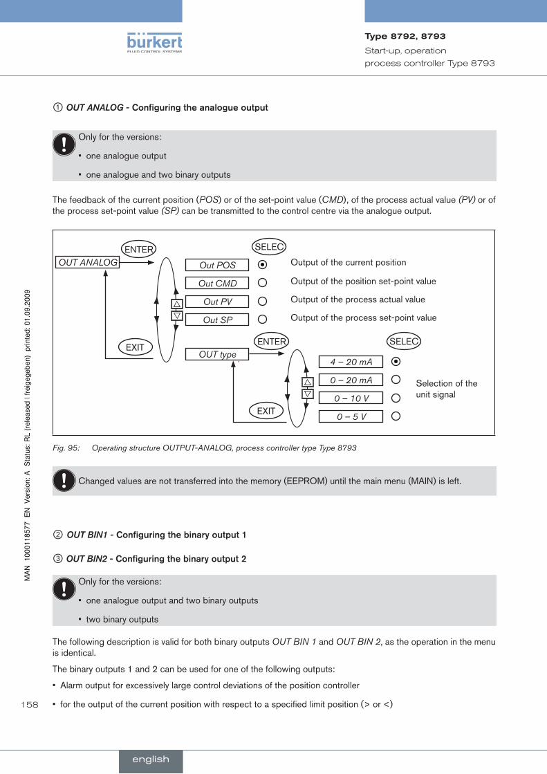
158
Start-up, operation
process controller Type 8793
① OUT ANALOG -.Configuring.the.analogue.output
Only for the versions:
one analogue output•
one analogue and two binary outputs•
The feedback of the current position (POS) or of the set-point value (CMD), of the process actual value (PV) or of the process set-point value (SP) can be transmitted to the control centre via the analogue output.
Out POS
EXITOUT type
Output of the current positionOUT ANALOG
Out CMD
Out PV
Out SP
Output of the position set-point value
Output of the process actual value
Output of the process set-point value
4 – 20 mA
Selection of the unit signal
0 – 20 mA
0 – 10 V
0 – 5 V
ENTER SELEC
SELECENTER
EXIT
Operating structure OUTPUT-ANALOG, process controller type Type 8793Fig. 95:
Changed values are not transferred into the memory (EEPROM) until the main menu (MAIN) is left.
②OUT BIN1 -.Configuring.the.binary.output.1
③ OUT BIN2 -.Configuring.the.binary.output.2
Only for the versions:
one analogue output and two binary outputs•
two binary outputs•
The following description is valid for both binary outputs OUT BIN 1 and OUT BIN 2, as the operation in the menu is identical.
The binary outputs 1 and 2 can be used for one of the following outputs:
Alarm output for excessively large control deviations of the position controller•
for the output of the current position with respect to a specified limit position (> or <)•
english
Type8792,8793
english
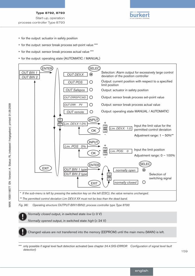
159
Start-up, operation
process controller Type 8793
for the output: actuator in safety position•
for the output: sensor break process set-point value ***•
for the output: sensor break process actual value ***•
for the output: operating state (AUTOMATIC / MANUAL)•
OUT DEV.X
Lim. DEV.X 1.0%
Selection: Alarm output for excessively large control deviation of the position controller
OUT BIN 1
OUT POS Output: current position with respect to a specified limit position
OUT Safepos Output: actuator in safety position
OUT ERRSP/CMD
OUT ERR PV
Output: sensor break process set-point value
Output: sensor break process actual value
INPUT+
-Lim. DEV.X: 1.0
OK*
Input the limit value for the permitted control deviation
Adjustment range: 1 – 50%**
Lim. POS 0%INPUT
+
-Lim. POS: 0* Input the limit position
Adjustment range: 0 – 100%
OUT BIN 1 type normally openSelection of switching signal
normally closed
OUT BIN 2
OUT BIN 2 type
OUT remote Output: operating state MANUAL / AUTOMATIC
EXIT
ENTER
SELECENTER
EXIT
SELEC
OK
* If the sub-menu is left by pressing the selection key on the left (ESC), the value remains unchanged.
** The permitted control deviation Lim DEV.X XX must not be less than the dead band.
Operating structure OUTPUT-BIN1/BIN2; process controller type Type 8793Fig. 96:
Normally closed output, in switched state low (≅ 0 V)
Normally opened output, in switched state high (≅ 24 V)
Changed values are not transferred into the memory (EEPROM) until the main menu (MAIN) is left.
*** only possible if signal level fault detection activated (see chapter 24.4.SIG-ERROR Configuration of signal level fault detection)
english
Type8792,8793
english
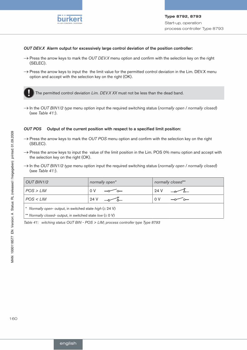
160
Start-up, operation
process controller Type 8793
OUT DEV.X..Alarm.output.for.excessively.large.control.deviation.of.the.position.controller:
Press the arrow keys to mark the .→ OUT DEV.X menu option and confirm with the selection key on the right (SELEC).
Press the arrow keys to input the.→ the limit value for the permitted control deviation in the Lim. DEV.X menu option and accept with the selection key on the right (OK).
The permitted control deviation Lim. DEV.X XX must not be less than the dead band.
In the .→ OUT BIN1/2 type menu option input the required switching status (normally open / normally closed) (see Table 41:).
OUT POS . Output.of.the.current.position.with.respect.to.a.specified.limit.position:
Press the arrow keys to mark the .→ OUT POS menu option and confirm with the selection key on the right (SELEC).
Press the arrow keys to input the.→ value of the limit position in the Lim. POS 0% menu option and accept with the selection key on the right (OK).
In the .→ OUT BIN1/2 type menu option input the required switching status (normally open / normally closed) (see Table 41:).
OUT BIN1/2 normally open* normally closed**
POS > LIM 0 V 24 V
POS < LIM 24 V 0 V
* Normally open- output, in switched state high (≅ 24 V)
** Normally closed- output, in switched state low (≅ 0 V)
Table 41: witching status OUT BIN - POS > LIM; process controller type Type 8793
english
Type8792,8793
english
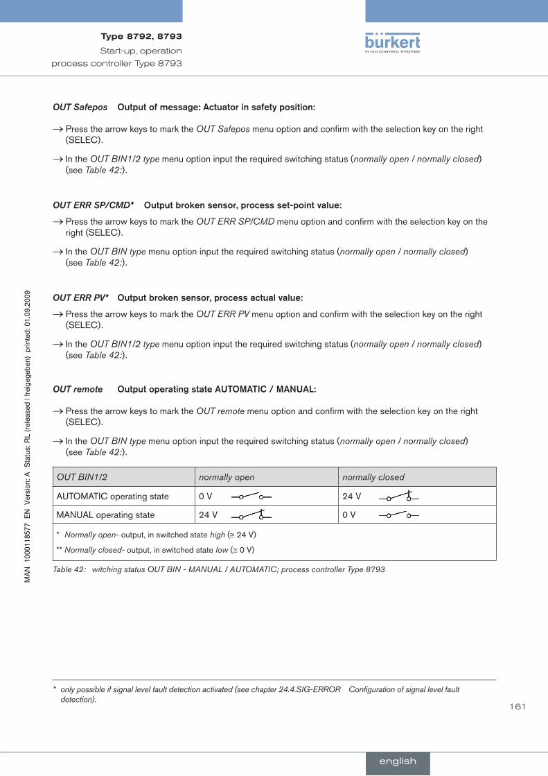
161
Start-up, operation
process controller Type 8793
OUT Safepos. Output.of.message:.Actuator.in.safety.position:.
Press the arrow keys to mark the .→ OUT Safepos menu option and confirm with the selection key on the right (SELEC).
In the .→ OUT BIN1/2 type menu option input the required switching status (normally open / normally closed) (see Table 42:).
OUT ERR SP/CMD*.. Output.broken.sensor,.process.set-point.value:
Press the arrow keys to mark the .→ OUT ERR SP/CMD menu option and confirm with the selection key on the right (SELEC).
In the .→ OUT BIN type menu option input the required switching status (normally open / normally closed) (see Table 42:).
OUT ERR PV*.. Output.broken.sensor,.process.actual.value:
Press the arrow keys to mark the .→ OUT ERR PV menu option and confirm with the selection key on the right (SELEC).
In the .→ OUT BIN1/2 type menu option input the required switching status (normally open / normally closed) (see Table 42:).
OUT remote.. Output.operating.state.AuTOMATIC./.MAnuAl:
Press the arrow keys to mark the .→ OUT remote menu option and confirm with the selection key on the right (SELEC).
In the .→ OUT BIN type menu option input the required switching status (normally open / normally closed) (see Table 42:).
OUT BIN1/2 normally open normally closed
AUTOMATIC operating state 0 V 24 V
MANUAL operating state 24 V 0 V
* Normally open- output, in switched state high (≅ 24 V)
** Normally closed- output, in switched state low (≅ 0 V)
Table 42: witching status OUT BIN - MANUAL / AUTOMATIC; process controller Type 8793
* only possible if signal level fault detection activated (see chapter 24.4.SIG-ERROR Configuration of signal level fault detection).
english
Type8792,8793
english
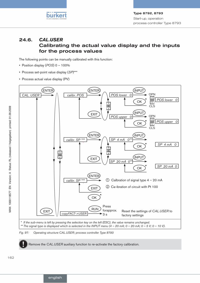
162
Start-up, operation
process controller Type 8793
24.6. CAL.USER calibratingtheactualvaluedisplayandtheinputsfortheprocessvalues
The following points can be manually calibrated with this function:
Position display (• POS) 0 – 100%
Process set-point value display (• SP)***
Process actual value display (PV) •
ENTER ENTER
EXIT
calibr. POSCAL. USER OPN
CLS
POS lower 0POS lower 0
INPUT
OK*
OPN
CLS
POS upper 0POS upper 0
*
calibr. SP ***
calibr. SP ***
SP 4 mA 0SP 4 mA 0**
*
SP 20 mA 0SP 20 mA 0**
*
copyFACT->USERRUN
Press forapprox. 3 s
Reset the settings of CAL.USER to factory settings
ENTER
ENTER
INPUT
INPUT
INPUTEXIT
EXIT
EXIT
OK
OK
OK
*OK
①②
Calbration of signal type 4 – 20 mA
Ca-ibration of circuit with Pt 100
* If the sub-menu is left by pressing the selection key on the left (ESC), the value remains unchanged. ** The signal type is displayed which is selected in the INPUT menu (4 – 20 mA; 0 – 20 mA; 0 – 5 V; 0 – 10 V).
Operating structure CAL.USER; process controller Type 8793Fig. 97:
Remove the CAL.USER auxiliary function to re-activate the factory calibration.
english
Type8792,8793
english

163
Start-up, operation
process controller Type 8793
procedure:
calibr. POS..Calibrating.the.actual.value.display.POS.(0.–.100%):
In the .→ CAL. USER menu press the arrow keys to select the calibr. POS and confirm with the selection key on the right (ENTER).
Accept the minimum position:
Press the arrow keys to mark the .→ POS lower X menu option and confirm with the selection key on the right (SELEC).
Approach the minimum position of the valve using the arrow keys (OPN/CLS) and confirm this value by pressing .→the selection key on the right (OK).
Accept the maximum position:
Press the arrow keys to mark the .→ POS upper X menu option and confirm with the selection key on the right (SELEC).
Approach the maximum position of the valve using the arrow keys (OPN/CLS) and confirm this value by pressing .→the selection key on the right (OK).
calibr. SP ***..Calibrating.the.process.set-point.value.(4.–.20.mA;.0.–.20.mA;.0.–.5.V;.0.–.10.V):
In the .→ CAL. USER menu press the arrow keys to select the calibr. INP and confirm with the selection key on the right (ENTER).
Accept the minimum input signal (0 mA; 4 mA; 0 V)**:
Using the arrow keys, select the .→ INP (0 mA; 4 mA; 0 V)** menu option and confirm with the selection key on the right (INPUT).
Specify the minimum value of the unit signal at the input and confirm this value with the selection key on the .→right (OK).
Accept the maximum input signal (20 mA; 5 V; 10 V)**:
Using the arrow keys, select the .→ INP (20 mA; 5 V; 10 V)** menu option and confirm with the selection key on the right (INPUT).
Specify the maximum value of the unit signal at the input and confirm this value with the selection key on the .→right (OK).
** The signal type is displayed which is selected in the INPUT menu (4 – 20 mA; 0 – 20 mA; 0 – 5 V; 0 – 10 V).
*** Only if external set-point value default is set in the P.CONTROL / SETUP / SP-INPUT menu
english
Type8792,8793
english
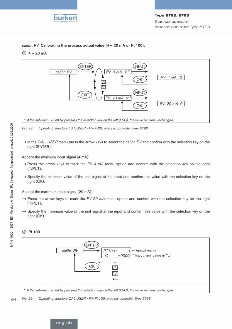
164
Start-up, operation
process controller Type 8793
calibr. PV..Calibrating.the.process.actual.value.(4.–.20.mA.or.Pt.100):
①.4.–.20.mA
calibr. PVPV 4 mA 0
PV 4 mA 0**INPUT
OK*
PV 20 mA 0PV 20 mA 0**
INPUT
OK*
ENTER
EXIT
* If the sub-menu is left by pressing the selection key on the left (ESC), the value remains unchanged.
Operating structure CAL.USER - PV-4-20; process controller Type 8793Fig. 98:
In the .→ CAL. USER menu press the arrow keys to select the calibr. PV and confirm with the selection key on the right (ENTER).
Accept the minimum input signal (4 mA):
Press the arrow keys to mark the .→ PV 4 mA menu option and confirm with the selection key on the right (INPUT).
Specify the minimum value of the unit signal at the input and confirm this value with the selection key on the .→right (OK).
Accept the maximum input signal (20 mA):
Press the arrow keys to mark the .→ PV 20 mA menu option and confirm with the selection key on the right (INPUT).
Specify the maximum value of the unit signal at the input and confirm this value with the selection key on the .→right (OK).
②.Pt.100
calibr. PV PT100 : 0 °C +0000
+
←
*
Input new value in °CActual value
ENTER
OK
* If the sub-menu is left by pressing the selection key on the left (ESC), the value remains unchanged.
Operating structure CAL.USER - PV-Pt 100; process controller Type 8793Fig. 99:
english
Type8792,8793
english
165
Start-up, operation
process controller Type 8793
Press the right selection key (ENTER) to select the input screen for .→ Pt 100.
On the display the last digit of the value is highlighted with a dark background.
Press the up arrow key (+) to specify the value of the individual digit. .→
Press the down arrow key (.→ ←) to switch to the next digit.
When all input values have been specified, confirm the values by pressing the right selection key (OK). .→The menu then jumps back to the selection screen.
copy FACT→USER.. resetting.the.settings.under.CAl.uSEr.to.the.factory.settings:.
In the .→ CAL.USER menu select the copy FACT→USER menu option using the arrow keys and confirm with the selection key on the right (ENTER).
Hold down the selection key on the right (RUN) (for approx. 3 seconds) until the countdown has elapsed..→
english
Type8792,8793
english

166
Start-up, operation
process controller Type 8793
english
Type8792,8793

167
conTenTs
25.. OPErATInG.STruCTurE.POSITIOnEr............................................................................................................................ 168
operating structure of the positioner
english
Type8792,8793

168
Operating structure of the positioner
OperaTingsTrucTurepOsiTiOner25.
ACTUATOR
INPUT
SINGLE
4 – 20 mA
DOUBLE
0 – 20 mA
0 – 10 V
0 – 5 V
Address X
BUS FAIL
BUS PDO *5
BUS.COMM *3
BUS PDI *5
X.TUNE
BAUDRATE *4
SafePos off
CMD / Setpoint*2
Address: XXX
SafePos on
Operation mode
Error reset
Position
CMD
Temperature
Operation mode
Errors
P.CONTRL active*1
P.CONTRL active*1
Process value *2
Setpoint *2
125 kBd
250 kBd
500 kBd
X.TUNE STARTED TUNE #0 INIT... TUNE READY
Operating structure - 1Fig. 100:
*1 only process controller 8793 *2 only process controller 8793 and activated process controller *3 only field bus *4 only DeviceNet *5 only Profibus DP
english
Type8792,8793
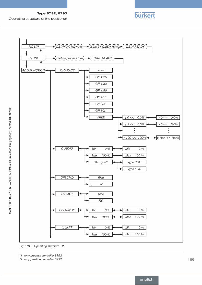
169
Operating structure of the positioner
ADD.FUNCTION CHARACT linear
GP 1:25
GP 1:33
GP 1:50
GP 25:1
GP 33:1
GP 50:1
FREE y 0 ->: 0,0%
y 5 ->: 5,0%
y 100 ->: 100%
y 0 ->: 0,0%
y 5 ->: 5,0%
y 100 ->: 100%
CUTOFF Min 0 %
Max 100 %
Min 0 %
Max 100 %
CUT type*1 Type PCO
Type XCO
DIR.CMD Rise
Fall
DIR.ACT Rise
Fall
SPLTRNG*2 Min 0 %
Max 100 %
Min 0 %
Max 100 %
X.LIMIT Min 0 %
Max 100 %
Min 0 %
Max 100 %
Q.LIN#0 CMD=0%
starting process tune
Q.LIN#1 CMD=10%... Q.LIN READY
TUNE READY
P.Q‘LIN
P.TUNE
Operating structure - 2Fig. 101:
*1 only process controller 8793 *2 only position controller 8792
english
Type8792,8793

170
Operating structure of the positioner
X.TIME Open 1
Close 1
Open 1
Close 1
X.CONTROL DBND 1%
KXopn 1
KXcls 1
DBND 1%
KXopn 0001
KXcls 0001
P.CONTROL*1 PARAMETER
SETUP
DBND 1%
KP 1.00
TN 999.9
TV 0.0
X0 0.0%
PV INPUT
PV SCALE
SP INPUT
FILTER 0
DBND 1%
KP 1.00
TN 999.9
TV 0.0
X0 0.0%
FILTER 0
4 – 20 mA
Frequenz
PT 100
PVmin 0.0
PVmin 0.0 bar
PVmax 100.0
PVmax 100.0 bar
K-Factor*2
VALUE TEACH IN
internal
external
Operating structure - 3Fig. 102:
*1 only process controller 8793 *2 only for frequency signal type (PV INPUT / frequency)
english
Type8792,8793

171
Operating structure of the positioner
P.CO INIT
SP SCALE*2
SPmin 0.0
SPmin 0.0 bar
SPmax 100.0
SPmax 100.0 bar
bumpless
standard
SECURITY CODE
MAIN
MANU/AUTO
ADDFUNCT
X.TUNE
P.Q‘LIN *1
Access Code CODE
Safepos Safepos 0% Safepos 0
SIG.ERROR SP/CMD Input
PV Input *1
ERROR off
SAFEPOS
ERROR on
SafePos off
SafePos on
ERROR off
SAFEPOS
ERROR on
SafePos off
SafePos on
Operating structure - 4Fig. 103:
*1 only process controller 8793 *2 only for external set-point value default (SP INPUT / external)
english
Type8792,8793
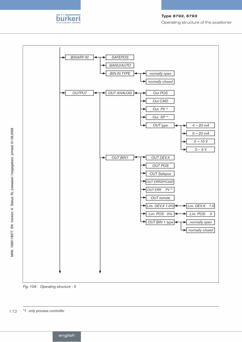
172
Operating structure of the positioner
SAFEPOS
BIN.IN TYPE
BINARY-IN
MANU/AUTO
normally open
normally closed
OUTPUT OUT ANALOG
OUT BIN1
Out POS
OUT type
Out CMD
Out PV *1
Out SP *1
4 – 20 mA
0 – 20 mA
0 – 10 V
0 – 5 V
OUT DEV.X
Lim. DEV.X 1.0%
OUT POS
OUT Safepos
OUT ERR PV *1
Lim. DEV.X: 1.0
Lim. POS 0% Lim. POS: 0
OUT BIN 1 type normally open
normally closed
OUT remote
OUT ERRSP/CMD
Operating structure - 5Fig. 104:
*1 only process controller
english
Type8792,8793

173
Operating structure of the positioner
OUT BIN2
PT100 0
OUT DEV.X
Lim. DEV.X 1.0%
OUT POS
OUT Safepos
OUT ERR PV *1
Lim. DEV.X: 1.0
Lim. POS 0% Lim. POS: 0
OUT BIN 2 type normally open
normally closed
OUT remote
OUT ERRSP/CMD
calibr. POSCAL. USER POS lower 0POS lower 0
POS upper 0POS upper 0
calibr. PV *5
copyFACT->USER
calibr. SP*4 SP 4 mA 0SP 4 mA 0*3
SP 20 mA 0SP 20 mA 0*3
calibr. INP*2 INP 4 mA 0INP 4 mA 0*3
INP 20 mA 0INP 20 mA 0*3
calibr. PV *6
PV 4 mA 0PV 4 mA 0
PV 20 mA 0PV 20 mA 0
SET.FACTORY Factory reset
Countdown
Operating structure - 6Fig. 105:
*1 only process controller 8793 *2 only position controller 8792 *3 The signal type is displayed which is selected in the INPUT menu *4 only 8793, only for external set-point value default (P.CONTROL / SETUP / SP-INPUT / external) *5 only 8793, only for signal type 4 – 20 mA *6 only 8793, only for circuit with PT 100
english
Type8792,8793
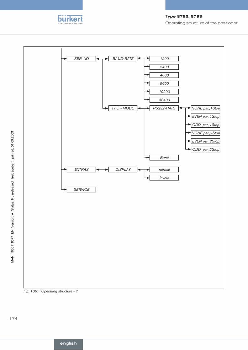
174
Operating structure of the positioner
SER. I\O BAUD-RATE
I / O - MODE
1200
2400
4800
9600
19200
38400
RS232-HART
Burst
NONE par.,1Stop
EVEN par.,1Stop
ODD par.,1Stop
NONE par.,2Stop
EVEN par.,2Stop
ODD par.,2Stop
normalEXTRAS
invers
DISPLAY
SERVICE
Operating structure - 7Fig. 106:
english
Type8792,8793

175
conTenTs
26.. GEnErAl.InFOrMATIOn........................................................................................................................................................... 176
27.. TEChnICAl.DATA........................................................................................................................................................................... 176
28.. SAFETY.SETTInGS.IF.ThE.BuS.FAIlS.............................................................................................................................. 177
29.. InTErFACES..................................................................................................................................................................................... 177
30.. ElECTrICAl.COnnECTIOnS.................................................................................................................................................. 178
30.1.. Connection.diagram.Type.8792................................................................................................................................ 179
30.2.. Connection.diagram.Type.8793................................................................................................................................ 179
30.3.. Operating.voltage.-.M12,.8-pole.connector....................................................................................................... 180
30.4.. Bus.connection.-.socket/connector.M12,.5-pole............................................................................................ 180
30.5.. Process.actual.value.(M8.circular.connector).-.Type.8793.only.............................................................. 181
31.. SETTInGS.On.ThE.POSITIOnEr.......................................................................................................................................... 182
31.1. BUS.COMMDescription.of.menu........................................................................................................................ 183
31.1.1.BUS.COMM Operating structure position controller ............................................................... 183
31.1.2.BUS.COMM Operating structure process controller .............................................................. 184
31.1.3.BUS.COMM Description of the menu options .......................................................................... 185
32.. FunCTIOnAl.DEVIATIOnS.FrOM.ThE.STAnDArD.MODEl................................................................................. 186
33.. COnFIGurATIOn.In.ThE.PrOFIBuS-DP.MASTEr.................................................................................................... 187
33.1.. Configuration.of.the.Process.Values..................................................................................................................... 187
34.. BuS.STATuS.DISPlAY................................................................................................................................................................ 189
35.. COnFIGurATIOn.WITh.SIEMEnS.STEP7........................................................................................................................ 190
35.1.. Example.1.of.a.position.controller.(Type.8792):.Transfer.of.set-point.and.actual.value........... 190
35.2.. Example.2.of.a.process.controller.(Type.8793):.Transfer.of.several.process.values.................. 191
profIBuS-dp
english
Type8792,8793
176
PROFIBUS-DP
generalinfOrMaTiOn26.The following sections of the general operating instructions do not apply to the positioner with PROFIBUS-DP:
Variants of the positioner•
Initial start-up•
Electrical connection•
Specifying the standard settings•
Function INPUT
Function SPLTRNG
Function BINARY-IN
Function OUTPUT
Function CAL.USER / calibr. INP
Function CAL.USER / calibr. SP
TechnicaldaTa27.The protocol sequence complies with the standard DIN 19245 Part 3.
GSD.file BUER0C1E.gsd
Bitmap.files BUER0C1E.bmp
PnO-ID. 0C1E Hex
Baud.rate Max. 12 mbaud (is automatically set by the positioner)
Sync.and.Freeze.mode Are not supported
Diagnosis.telegram No device-specific diagnosis
Parameter.telegram No user parameters
The process data is configured in the positioner and in the PROFIBUS master.
Maximum 10 process values (total INPUT and OUTPUT) can be transferred.
english
Type8792,8793
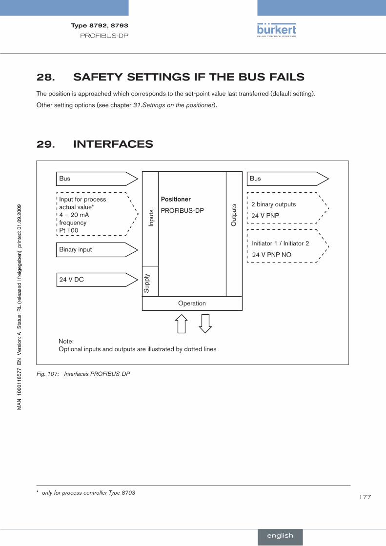
177
PROFIBUS-DP
safeTyseTTingsifTheBusfails28.The position is approached which corresponds to the set-point value last transferred (default setting).
Other setting options (see chapter 31.Settings on the positioner).
inTerfaces29.
Input for process actual value* 4 – 20 mA frequency Pt 100
Binary input
24 V DC
Positioner
PROFIBUS-DP2 binary outputs
24 V PNP
Initiator 1 / Initiator 2
24 V PNP NO
Inpu
ts
Out
puts
Sup
ply
Operation
Note: Optional inputs and outputs are illustrated by dotted lines
BusBus
Interfaces PROFIBUS-DPFig. 107:
* only for process controller Type 8793
english
Type8792,8793

178
PROFIBUS-DP
elecTricalcOnnecTiOns30.
danGer!
risk.of.injury.due.to.electrical.shock!
Before reaching into the device or the equipment, switch off the power supply and secure to prevent • reactivation!
Observe applicable accident prevention and safety regulations for electrical equipment!•
WarnInG!
risk.of.injury.from.improper.installation!
Installation may be carried out by authorized technicians only and with the appropriate tools!•
risk.of.injury.from.unintentional.activation.of.the.system.and.an.uncontrolled.restart!
Secure system from unintentional activation.•
Following installation, ensure a controlled restart.•
For operation of the device always connect the 5-pole, inversely coded M12 socket and the 8-pole M12 plug .→(power supply).
note!
Electromagnetic.compatibility.(EMC).is.only.ensured.if.the.appliance.is.connected.correctly.to.an.earthing.point.
On the outside of the housing is a TE terminal for connection of the technical earth (TE).
Connect the TE terminal to the earthing point via a shortest possible cable (maximum length 30 cm).•
english
Type8792,8793

179
PROFIBUS-DP
connectiondiagramType879230.1.
12
3
4
5
6
7
8
M12, 8-pole plug M12, 5-pole plug (inversely coded, PROFIBUS-DP)
1
43
25
M12, 5-pole socket (inversely coded, PROFIBUS-DP)
FunctionearthFE
2
34
1
5
Connection PROFIBUS-DP, position controller Typ 8792Fig. 108:
connectiondiagramType879330.2.
12
3
4
5
6
7
8
M12, 5-pole plug (inversely coded, PROFIBUS-DP)
2
34
1
5
M8, 4-pole plug
M12, 8-pole plug
1
43
25
M12, 5-pole socket (inversely coded, PROFIBUS-DP)
FunctionearthFE
24
3 1
Fig. 109: Connection PROFIBUS-DP, process controller Typ 8793
english
Type8792,8793
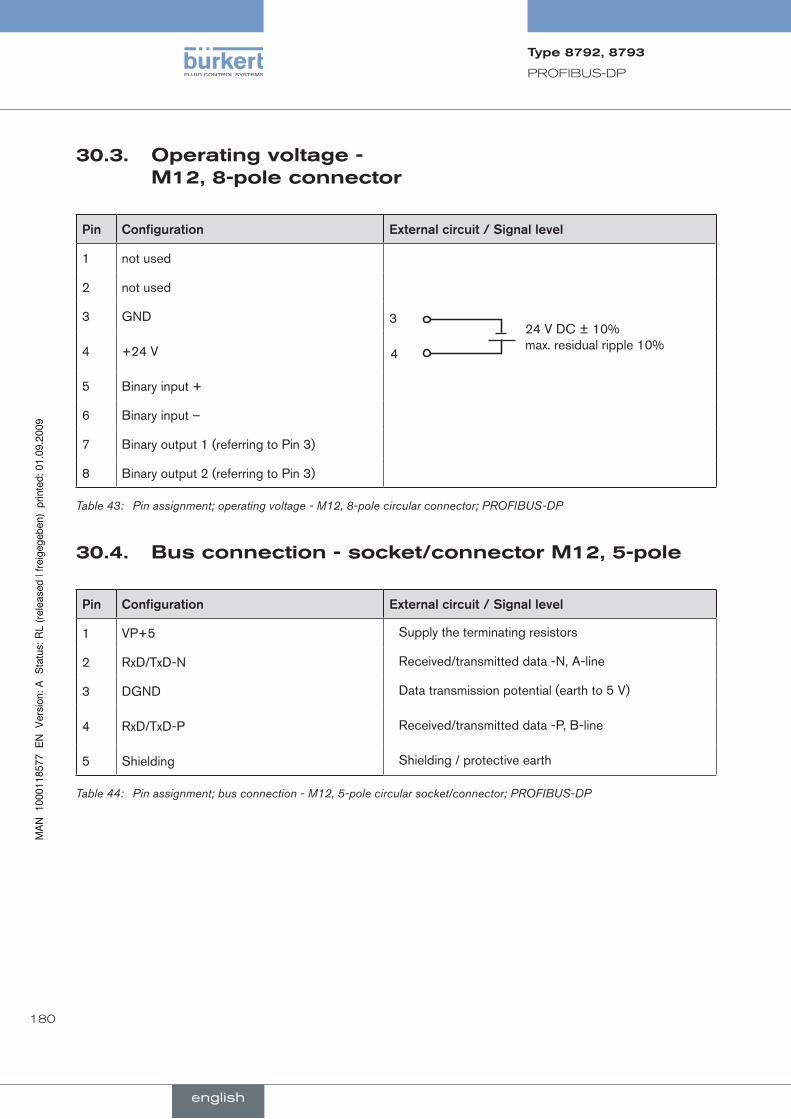
180
PROFIBUS-DP
Operatingvoltage-30.3.M12,8-poleconnector
Pin Configuration External.circuit./.Signal.level
1 not used
2 not used
3 GND 3
4
24 V DC ± 10% max. residual ripple 10%4 +24 V
5 Binary input +
6 Binary input –
7 Binary output 1 (referring to Pin 3)
8 Binary output 2 (referring to Pin 3)
Pin assignment; operating voltage - M12, 8-pole circular connector; PROFIBUS-DPTable 43:
Busconnection-socket/connectorM12,5-pole30.4.
Pin Configuration External.circuit./.Signal.level
1 VP+5 Supply the terminating resistors
2 RxD/TxD-N Received/transmitted data -N, A-line
3 DGND Data transmission potential (earth to 5 V)
4 RxD/TxD-P Received/transmitted data -P, B-line
5 Shielding Shielding / protective earth
Pin assignment; bus connection - M12, 5-pole circular socket/connector; PROFIBUS-DPTable 44:
english
Type8792,8793

181
PROFIBUS-DP
processactualvalue(M8circularconnector)-30.5.Type8793only
Input.type* Pin ConfigurationDIP.switches**
External.circuit
4 – 20 mA - internally supplied
1 +24 V transmitter supply
Switch on left
1
2
34
Transmitter
GND
I2 Output from transmitter
3 GND
4 Bridge after GND (GND from 3-conductor transmitter)
4 – 20 mA - externally supplied
1 not used
Switch on right
2 Process actual + 2 4 – 20 mA
3 not used
4 Process actual – 4 GND
Frequency - internally supplied
1 +24 V sensor supply
Switch on left
1 +24 V
2 Clock input + 2 Clock +
3 Clock input – (GND) 3 Clock –
4 not used
Frequency - externally supplied
1 not used
Switch on right
2 Clock input + 2 Clock +
3 Clock input – 3 Clock –
4 not used
Pt 100 (see information below)
1 not used
Switch on right
2
34
Pt 1002 Process actual 1 (power supply)
3 Process actual 3 (GND)
4 Process actual 2 (compensation)
* Can be adjusted via software (see chapter 18.3.Specifying the standard settings).
** The switch is located under the screw connection (see Fig. 109:Connection PROFIBUS-DP, process controller Typ 8793)
Plug assignments of the process actual value input (M8 circular plug)Table 45:
Connect the Pt 100 sensor via 3 cables for cable compensation reasons. It is essential to bridge Pin 3 and Pin 4 on the sensor.
english
Type8792,8793

182
PROFIBUS-DP
31. seTTingsOnThepOsiTiOner
Specify the basic settings on the positioner for .→ ACTUATOR and X.TUNE.
Specification of the basic settings is described in the chapter entitled Start-up and operation of the position controller Type 8792 / 19.5.Specifying the standard settings.
Implement the settings in the .→ BUS.COMM menu option. The procedure is described in the following chapter 31.1.BUS.COMM Description of menu.
Operating state
AUTOMATIC
or
MANUAL
MENUACTUATOR
BUS.COMM
X.TUNE
ADD.FUNCTION
SINGLE
SAVE EEPROM
Address 0
approx. 3 s
ca. 3 sX.TUNE
STARTED
TUNE #0 INIT
X.TUNE READY
CHARACT
DOUBLE
BUS FAIL
BUS PDI
BUS PDO
CUTOFF
SERVICE
ENTERENTER
ENTER
ENTER
ENTER
ENTER
ENTER
ENTER
INPUT
SELEC
EXIT
EXIT
EXIT
EXIT
EXIT
RUN
Operating structure - basic settings - PROFIBUS-DPFig. 110:
english
Type8792,8793

183
PROFIBUS-DP
31.1. BUS.COMMdescriptionofmenu
31.1.1. BUS.COMMOperatingstructurepositioncontroller
OK
Address X
BUS FAIL
BUS PDO
+
-
SafePos off
CMD
Address: XXX
SafePos on
Operation mode
Error reset
BUS.COMM
BUS PDI Position
CMD
Temperature
Operation mode
Errors
ENTER
ENTER
ENTER
ENTER
ENTER
ENTER
SELEC
EXIT
EXIT
EXIT
EXIT
INPUT
Operating structure - BUS-COMM; position controller 8792Fig. 111:
english
Type8792,8793

184
PROFIBUS-DP
31.1.2. BUS.COMMOperatingstructureprocesscontroller
OK
Address X
BUS FAIL
BUS PDO
+
-Address: XXX
BUS.COMM
BUS PDI
SafePos off
Setpoint**
SafePos on
Operation mode
P.CONTROL active
Error reset
Position
CMD
Process value*
Setpoint
Temperature
Operation mode
Errors
P.CONTROL active
ENTER
ENTER
ENTER
ENTER
ENTER
ENTER
SELEC
EXIT
EXIT
EXIT
EXIT
INPUT
* only when process controller activated ** only when process controller activated, otherwise CMD
Operating structure - BUS-COMM; process controller 8793Fig. 112:
english
Type8792,8793
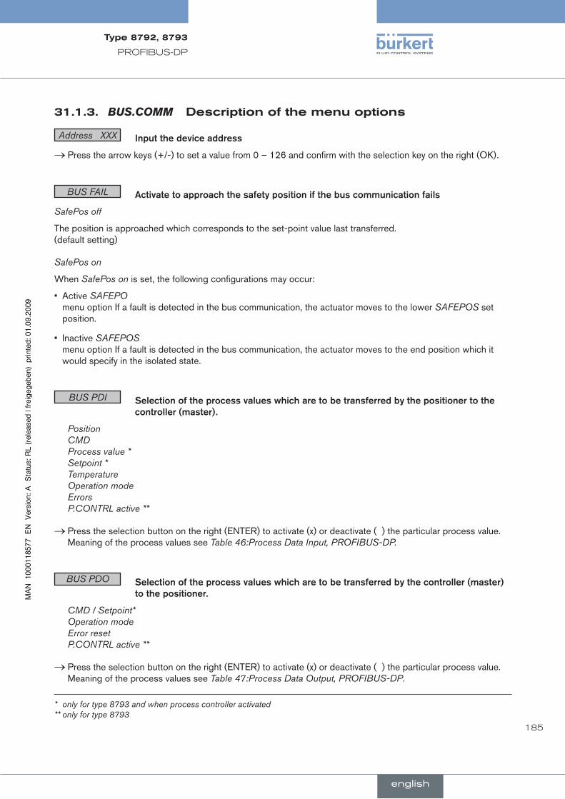
185
PROFIBUS-DP
31.1.3. BUS.COMMdescriptionofthemenuoptions
Address XXX Input.the.device.address
Press the arrow keys (+/-) to set a value from 0 – 126 and confirm with the selection key on the right (OK)..→
BUS FAIL Activate.to.approach.the.safety.position.if.the.bus.communication.fails
SafePos off
The position is approached which corresponds to the set-point value last transferred. (default setting)
SafePos on
When SafePos on is set, the following configurations may occur:
Active • SAFEPO menu option If a fault is detected in the bus communication, the actuator moves to the lower SAFEPOS set position.
Inactive • SAFEPOS menu option If a fault is detected in the bus communication, the actuator moves to the end position which it would specify in the isolated state.
BUS PDI .Selection.of.the.process.values.which.are.to.be.transferred.by.the.positioner.to.the.controller.(master).
Position CMD Process value * Setpoint * Temperature Operation mode Errors P.CONTRL active **
Press the selection button on the right (ENTER) to activate (x) or deactivate ( ) the particular process value..→Meaning of the process values see Table 46:Process Data Input, PROFIBUS-DP.
BUS PDO .Selection.of.the.process.values.which.are.to.be.transferred.by.the.controller.(master).to.the.positioner.
CMD / Setpoint* Operation mode Error reset P.CONTRL active **
Press the selection button on the right (ENTER) to activate (x) or deactivate ( ) the particular process value. .→Meaning of the process values see Table 47:Process Data Output, PROFIBUS-DP.
* only for type 8793 and when process controller activated ** only for type 8793
english
Type8792,8793
186
PROFIBUS-DP
funcTiOnaldeviaTiOnsfrOMThe32.sTandardMOdel
It is possible to switch between the MANUAL and AUTOMATIC operating states on the process operating level either via the keyboard on the positioner or via the bus.
It is no longer possible to switch between MANUAL / AUTOMATIC on the keyboard if an operating mode (under PDO MODE) is transferred to the positioner via the bus.
english
Type8792,8793

187
PROFIBUS-DP
cOnfiguraTiOninTheprOfiBus-dp33.MasTer
User parameters (hexparameters) are not required.
configurationoftheprocessvalues33.1.
The PDI (Process Data Input) input first..→
PDI: Process.Data.Input (from the positioner to the controller)
name Description Identifier
PDI:POS Actual position (position)
Actual value of position controller as ‰. Value range 0 – 1000. Values < 0 or > 1000 are possible if e.g. Autotune has not run through correctly.
GSD file: PDI:POS
Identifier (HEX): 41, 40, 00
PDI:CMD Nominal position (command)
Set-point value of position controller as ‰. Value range 0 – 1000.
GSD file: PDI:CMD
Identifier (HEX): 41, 40, 01
PDI:PV
PDI:SP
Process actual value (process value)
Actual value of process controller in physical unit (as set in the menu P.CO INP or P.CO SCAL), max. value range -999 – 9999, depending on internal scaling
Process set-point value (setpoint)
Set-point value of process controller in physical unit (as set in the menu P.CO INP or P.CO SCAL), max. value range -999 – 9999, depending on internal scaling
GSD file: PDI:PV
Identifier (HEX): 41, 40, 02
GSD file: PDI:SP
Identifier (HEX): 41, 40, 03
PDI:TEMP Device temperature (temperature)
Temperature of 0.1 °C is measured on the CPU board by the sensor,
Value range -550 (-55 °C) – +1250 (+125 °C)
GSD file: PDI:TEMP
Identifier (HEX): 41, 40, 04
PDI:MODE Operating mode (operation mode)
Operating mode:
GSD file: PDI:MODE
0: AUTO
1: MANUAL
2: XTUNE
9: P.QLIN
10: P.TUNE
12: BUSSAFEPOS Identifier (HEX): 41, 00, 05
english
Type8792,8793

188
PROFIBUS-DP
name Description Identifier
PDI:ERR Error
Indicates the number of the process value (output) which was not written. The value is retained until it is deleted with PDO:ERR.
HEX
14 PDO:CMD / SP
16 PDO:MODE
GSD file: PDI:ERR
Identifier (HEX): 41, 00, 06
PDI: PCONact
0: Position controller
1: Process controller
GSD file: PDI:PCONact
Identifier (HEX): 41, 00, 0A
Table 46: Process Data Input, PROFIBUS-DP
PDI:PV and PDI:SP can be selected for Type 8793 (process controller) only and are beneficial only when process controller activated.PDI:PCONact can be selected for Type 8793 (process controller) only.
Then the process data output input..→
PDO: Process.Data.Output (from the controller to the positioner)
name Description Identifier
PDO:CMD/SP
for position controller Type 8792: Set-point position (input)
Set-point value of position controller as ‰. Value range 0 – 1000
If the value is too small or too large, the last valid value is used and is indicated in ERR with HEX 14.
GSD file: PDO:CMD/SP
Identifier (HEX): 81, 40, 14
for process controller Type 8793: Process set-point value (setpoint)
Set-point value of process controller in physical unit (as set in the menu P.CO INP or P.CO SCAL), max. value range -999 – 9999, depending on internal scaling.
If the value is too small or too large, the last valid value is used and is indicated in ERR with HEX 14.
PDO:MODE Operating mode (operation mode)
Value range 0, 1 or 12:
0: AUTO / 1: HAND / 12: BUSSAFEPOS
If the value is too small or too large, the last valid value is used and is indicated in ERR with HEX 16.
GSD file: PDO:MODE
Identifier (HEX): 81, 00, 16
PDO:ERR Reset error display
If the value > 0, ERR is reset
GSD file: PDO:ERR
Identifier (HEX): 81, 00, 17
PDO: CONact
0: Position controller
1: Process controller
GSD file: PDO:CONact
Identifier (HEX): 81, 00, 19
Table 47: Process Data Output, PROFIBUS-DP
english
Type8792,8793

189
PROFIBUS-DP
BussTaTusdisplay34.The bus status is indicated on the display on the device.
Display Device.status Explanation Troubleshooting
BUS offline
is displayed approx. every 3 seconds
offline
Device is not connected to the bus
Bus connection including • plug assignment correct.
Check power supply and • bus connection of the other nodes.
Bus status display; PROFIBUS-DPTable 48:
english
Type8792,8793

190
PROFIBUS-DP
cOnfiguraTiOnWiThsieMenssTep735.
example1ofapositioncontroller(Type8792):35.1.Transferofset-pointandactualvalue
ScreenShot PROFIBUS Fig. 113:
Pull the slave Type 8792 / 8793 onto the bus line with drag-and-drop..→
ScreenShot position controllerFig. 114:
Pull the modules PDI:POS and PDO:CMD/SP into the slave Type 8792 / 8793 with drag-and-drop..→
english
Type8792,8793

191
PROFIBUS-DP
example2ofaprocesscontroller(Type8793):35.2.Transferofseveralprocessvalues.
ScreenShot PROFIBUSFig. 115:
Pull the slave Type 8792 / 8793 onto the bus line with drag-and-drop..→
ScreenShot process controllerFig. 116:
Pull the modules into the slave Type 8792 / 8793 with drag-and-drop..→
english
Type8792,8793
192
PROFIBUS-DP
english
Type8792,8793
193
conTenTs
36.. MAInTEnAnCE................................................................................................................................................................................ 194
37.. ErrOr.MESSAGES.AnD.MAlFunCTIOnS..................................................................................................................... 194
37.1.. Error.Messages.on.the.Display................................................................................................................................. 194
37.1.1. General Error Messages ..................................................................................................................... 194
37.1.2. Error and warning messages while the X.TUNE function is running ................................... 195
37.2.. Other.faults.......................................................................................................................................................................... 195
Servicing and troubleshooting the position controller type 8792
english
Type8792,8793

194
Servicing and Troubleshooting the Position Controller Type 8792
MainTenance36.The.positioner.Type.8792.is.maintenance-free.when.operated.according.to.the.instructions.in.this.manual.
errOrMessagesandMalfuncTiOns37.
37.1. errorMessagesonthedisplay
generalerrorMessages37.1.1.
Display Causes.of.error remedial.action
min
Minimum input value has been reached Do not reduce value further
max
Maximum input value has been reached Do not increase value further
CMD error Signal error
Set-point value position controller
Check signal
EEPROM fault EEPROM defective Not possible, device defective
MFI fault Field bus board defective
invalid code Incorrect access code Input correct access code
General error message, position controller Type 8792Table 49:
english
Type8792,8793
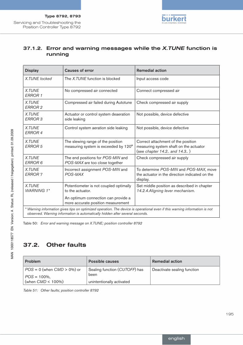
195
Servicing and Troubleshooting the Position Controller Type 8792
37.1.2. errorandwarningmessageswhiletheX.TUNEfunctionisrunning
Display Causes.of.error remedial.action
X.TUNE locked The X.TUNE function is blocked Input access code
X.TUNE ERROR 1
No compressed air connected Connect compressed air
X.TUNE ERROR 2
Compressed air failed during Autotune Check compressed air supply
X.TUNE ERROR 3
Actuator or control system deaeration side leaking
Not possible, device defective
X.TUNE ERROR 4
Control system aeration side leaking Not possible, device defective
X.TUNE ERROR 5
The slewing range of the position measuring system is exceeded by 120°
Correct attachment of the position measuring system shaft on the actuator (see chapter 14.2.. and 14.3.. )
X.TUNE ERROR 6
The end positions for POS-MIN and POS-MAX are too close together
Check compressed air supply
X.TUNE ERROR 7
Incorrect assignment POS-MIN and POS-MAX
To determine POS-MIN and POS-MAX, move the actuator in the direction indicated on the display.
X.TUNE WARNING 1*
Potentiometer is not coupled optimally to the actuator.
An optimum connection can provide a more accurate position measurement
Set middle position as described in chapter 14.2.4.Aligning lever mechanism.
* Warning information gives tips on optimized operation. The device is operational even if this warning information is not observed. Warning information is automatically hidden after several seconds.
Table 50: Error and warning message on X.TUNE; position controller 8792
Otherfaults37.2.
Problem Possible.causes remedial.action
POS = 0 (when CMD > 0%) or
POS = 100%, (when CMD < 100%)
Sealing function (CUTOFF) has been
unintentionally activated
Deactivate sealing function
Other faults; position controller 8792Table 51:
english
Type8792,8793
196
Servicing and Troubleshooting the Position Controller Type 8792
english
Type8792,8793
197
conTenTs
38.. MAInTEnAnCE................................................................................................................................................................................ 198
39.. ErrOr.MESSAGES.AnD.MAlFunCTIOnS..................................................................................................................... 198
39.1.. Error.Messages.on.the.Display................................................................................................................................. 198
39.1.1. General Error Messages ..................................................................................................................... 198
39.1.2. Error and warning messages while the X.TUNE function is running ................................... 199
39.1.3. Error Messages while the P.Q'LIN Function is Running .......................................................... 200
39.1.4. Error Messages while the P.TUNE Function is Running ......................................................... 200
39.1.5. Error Messages on Field Bus Devices ............................................................................................ 201
39.2.. Other.faults.......................................................................................................................................................................... 202
Servicing and troubleshooting the process controller type 8793
english
Type8792,8793

198
Servicing and Troubleshooting the Process Controller Type 8793
MainTenance38.The.positioner.Type.8793.is.maintenance-free.when.operated.according.to.the.instructions.in.this.manual.
errOrMessagesandMalfuncTiOns39.
39.1. errorMessagesonthedisplay
generalerrorMessages39.1.1.
Display Causes.of.error remedial.action
min
Minimum input value has been reached Do not reduce value further
max
Maximum input value has been reached Do not increase value further
CMD error Signal error
Set-point value position controller
Check signal
SP error Signal error
Set-point value process controller
Check signal
PV error Signal error
Actual value process controller
Check signal
PT100 error Signal error
Actual value Pt-100
Check signal
invalid code Incorrect access code Input correct access code
EEPROM fault EEPROM defective Not possible, device defective
MFI fault * Field bus board defective
* field bus only
General error message, process controller Type 8793Table 52:
english
Type8792,8793

199
Servicing and Troubleshooting the Process Controller Type 8793
errorandwarningmessageswhilethe39.1.2. X.TUNEfunctionisrunning
Display Causes.of.error remedial.action
X.TUNE locked The X.TUNE function is blocked Input access code
X.TUNE ERROR 1
No compressed air connected Connect compressed air
X.TUNE ERROR 2
Compressed air failed during Autotune Check compressed air supply
X.TUNE ERROR 3
Actuator or control system deaeration side leaking
Not possible, device defective
X.TUNE ERROR 4
Control system aeration side leaking Not possible, device defective
X.TUNE ERROR 5
The slewing range of the position measuring system is exceeded by 120°
Correct attachment of the position measuring system shaft on the actuator (see chapter 14.2. and 14.3.)
X.TUNE ERROR 6
The end positions for POS-MIN and POS-MAX are too close together
Check compressed air supply
X.TUNE ERROR 7
Incorrect assignment POS-MIN and POS-MAX
To determine POS-MIN and POS-MAX, move the actuator in the direction indicated on the display.
X.TUNE WARNING 1*
Potentiometer is not coupled optimally to the actuator.
An optimum connection can provide a more accurate position measurement.
Set middle position as described in chapter 14.2.4.Aligning lever mechanism.
* Warning information gives tips on optimized operation. The device is operational even if this warning information is not observed. Warning information is automatically hidden after several seconds.
Error and warning message for X.TUNE; process controller 8793Table 53:
english
Type8792,8793
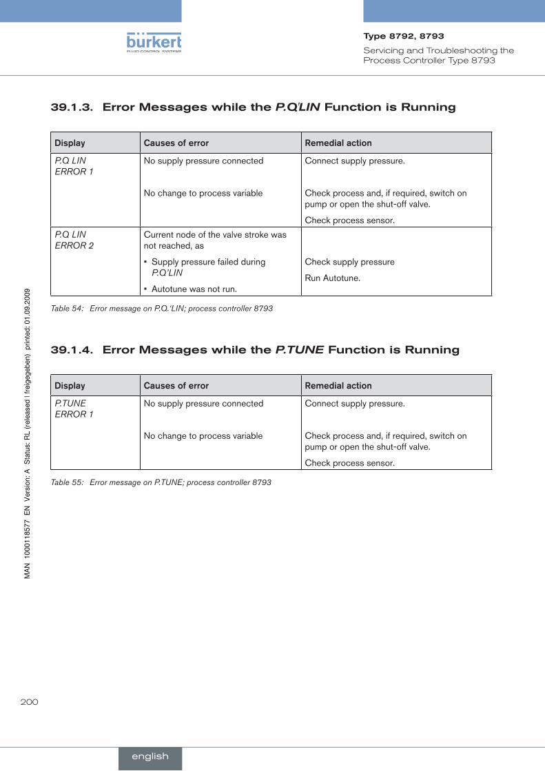
200
Servicing and Troubleshooting the Process Controller Type 8793
errorMessageswhilethe39.1.3. P.Q'LINfunctionisrunning
Display Causes.of.error remedial.action
P.Q LIN ERROR 1
No supply pressure connected
No change to process variable
Connect supply pressure.
Check process and, if required, switch on pump or open the shut-off valve.
Check process sensor.
P.Q LIN ERROR 2
Current node of the valve stroke was not reached, as
Supply pressure failed during • P.Q’LIN
Autotune was not run.•
Check supply pressure
Run Autotune.
Error message on P.Q.‘LIN; process controller 8793Table 54:
errorMessageswhilethe39.1.4. P.TUNEfunctionisrunning
Display Causes.of.error remedial.action
P.TUNE ERROR 1
No supply pressure connected
No change to process variable
Connect supply pressure.
Check process and, if required, switch on pump or open the shut-off valve.
Check process sensor.
Error message on P.TUNE; process controller 8793Table 55:
english
Type8792,8793
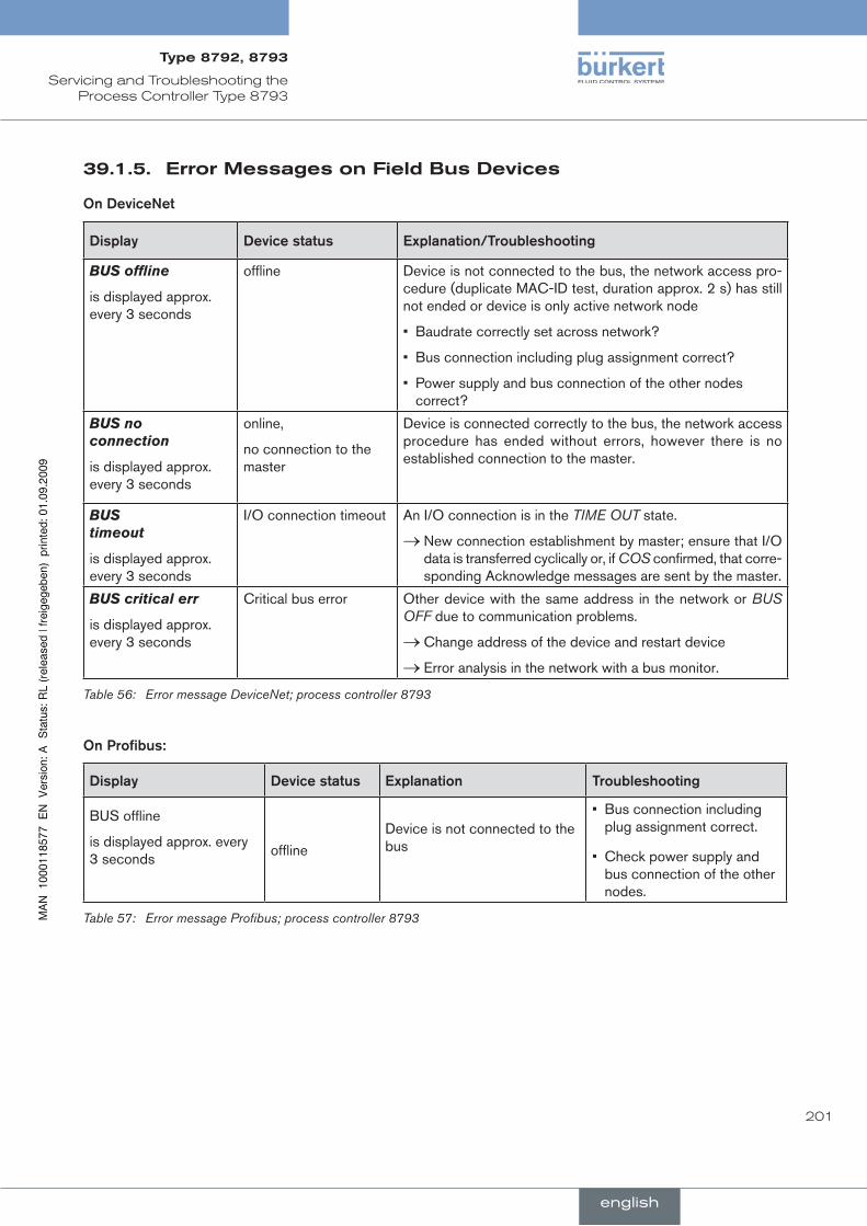
201
Servicing and Troubleshooting the Process Controller Type 8793
errorMessagesonfieldBusdevices39.1.5.
On.Devicenet
Display Device.status Explanation/Troubleshooting
BUSoffline
is displayed approx. every 3 seconds
offline Device is not connected to the bus, the network access pro-cedure (duplicate MAC-ID test, duration approx. 2 s) has still not ended or device is only active network node
Baudrate correctly set across network?•
Bus connection including plug assignment correct?•
Power supply and bus connection of the other nodes • correct?
BUSnoconnection
is displayed approx. every 3 seconds
online,
no connection to the master
Device is connected correctly to the bus, the network access procedure has ended without errors, however there is no established connection to the master.
BUStimeout
is displayed approx. every 3 seconds
I/O connection timeout An I/O connection is in the TIME OUT state.
New connection establishment by master; ensure that I/O →data is transferred cyclically or, if COS confirmed, that corre-sponding Acknowledge messages are sent by the master.
BUScriticalerr
is displayed approx. every 3 seconds
Critical bus error Other device with the same address in the network or BUS OFF due to communication problems.
Change address of the device and restart device →Error analysis in the network with a bus monitor. →
Error message DeviceNet; process controller 8793Table 56:
On.Profibus:
Display Device.status Explanation Troubleshooting
BUS offline
is displayed approx. every 3 seconds
offline
Device is not connected to the bus
Bus connection including • plug assignment correct.
Check power supply and • bus connection of the other nodes.
Error message Profibus; process controller 8793Table 57:
english
Type8792,8793
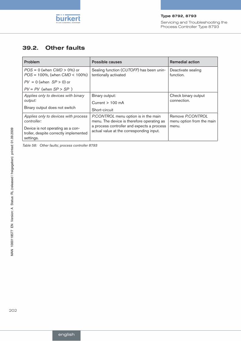
202
Servicing and Troubleshooting the Process Controller Type 8793
Otherfaults39.2.
Problem Possible.causes remedial.action
POS = 0 (when CMD > 0%) or POS = 100%, (when CMD < 100%)
PV = 0 (when SP > 0) or
PV = PV (when SP > SP )
Sealing function (CUTOFF) has been unin-tentionally activated
Deactivate sealing function.
Applies only to devices with binary output:
Binary output does not switch
Binary output:
Current > 100 mA
Short-circuit
Check binary output connection.
Applies only to devices with process controller:
Device is not operating as a con-troller, despite correctly implemented settings.
P.CONTROL menu option is in the main menu. The device is therefore operating as a process controller and expects a process actual value at the corresponding input.
Remove P.CONTROL menu option from the main menu.
Other faults; process controller 8793Table 58:
english
Type8792,8793

203
conTenTs
40.. PACKAGInG.AnD.TrAnSPOrT............................................................................................................................................. 204
41.. STOrAGE............................................................................................................................................................................................ 204
42.. DISPOSAl.......................................................................................................................................................................................... 204
packaging, Storage, disposal
english
Type8792,8793

204
Packaging, Storage, Disposal
pacKagingandTranspOrT40.
note!
Transport.damages!
Inadequately protected equipment may be damaged during transport.
During transportation protect the device against wet and dirt in shock-resistant packaging. •
Avoid exceeding or dropping below the allowable storage temperature.•
sTOrage41.
note!
Incorrect.storage.may.damage.the.device.
Store the device in a dry and dust-free location!•
Storage temperature. -20 – +65 °C.•
dispOsal42.Dispose of the device and packaging in an environmentally friendly manner. →
note!
Damage.to.the.environment.caused.by.device.components.contaminated.with.media.
Observe applicable disposal regul• ations and environmental regulations.
Observe national waste disposal regulations.
english
Type8792,8793
205
conTenTs
43.. SElECTIOn.CrITErIA.FOr.COnTInuOuS.VAlVES.................................................................................................. 206
44.. PrOPErTIES.OF.PID.COnTrOllErS................................................................................................................................ 208
44.1.. P-portion................................................................................................................................................................................ 208
44.2.. I-portion.................................................................................................................................................................................. 209
44.3.. D-portion................................................................................................................................................................................ 210
44.4.. Superposition.of.P,.I.and.D.Portions...................................................................................................................... 211
44.5.. Implemented.PID.controller........................................................................................................................................ 212
44.5.1. D Portion with Delay ............................................................................................................................ 212
44.5.2. Function of the Real PID Controller ................................................................................................. 212
45.. ADjuSTMEnT.rulES.FOr.PID.COnTrOllErS........................................................................................................... 213
45.1.. Adjustment.rules.according.to.ziegler.and.nichols.(Oscillation.Method)....................................... 213
45.2.. Adjustment.rules.according.to.Chien,.hrones.and.reswick..(Actuating.Variable.jump.Method).......................................................................................................................... 215
additional technical information
english
Type8792,8793

206
Additional technical information
selecTiOncriTeriafOrcOnTinuOus43.valves
The following criteria are crucial for optimum control behaviour and to ensure that the required maximum flow is reached:
the correct selection of the flow coefficient which is defined primarily by the orifice of the valve;•
close coordination between the nominal width of the valve and the pressure conditions in consideration of the • remaining flow resistance in the equipment.
Design guidelines can be given on the basis of the flow coefficient (kV value). The kV value refers to standardised conditions with respect to pressure, temperature and media properties.
The kV value describes the flow rate of water through a component in m³/h at a pressure difference of ∆p = 1 bar and T = 20 °C.
The “kVS value” is also used for continuous valves. This indicates the kV value when the continuous valve is fully open.
Depending on the specified data, it is necessary to differentiate between the two following cases when selecting the valve:
a) The pressure values p1 and p2, known before and after the valve, represent the required maximum flow-rate Qmax which is to be reached:
The required kVS value is calculated as follows:
(1)pp
Qk0
0max s v
ρρ
⋅∆∆
= ⋅
Meaning of the symbols: kVS flow coefficient of the continuous valve when fully open [m³/h] Qmax maximum volume flow rate [m³/h] ∆p0 = 1 bar; pressure loss on the valve according to the definition of the kV value ρ0 = 1000 kg/m³; density of water (according to the definition of the kV value) ∆p pressure loss on the valve [bar] ρ density of the medium [kg/m³]
b) The pressure values, known at the input and output of the entire equipment (p1 and p2), represent the required maximum flow-rate Qmax which is to be reached:
1st step: Calculate the flow coefficient of the entire equipment kVges according to equation (1).
2nd step: Determine the flow-rate through the equipment without the continuous valve (e.g. by "short-circuiting" the line at the installation location of the continuous valve).
3rd step: Calculate the flow coefficient of the equipment without the continuous valve (kVa) according to equation (1).
4th step: Calculate the required kVS value of the continuous valve according to equation (2):
(2)
²k1
²k1
1k
a VVges
s v
−=
english
Type8792,8793

207
Additional technical information
The kVS value of the continuous valve should have at least the value which is calculated according to equation (1) or (2) which is appropriate to the application, however it should never be far above the calcu-lated value.
The rule of thumb "slightly higher is never harmful" often used for switching valves may greatly impair the control behaviour of continuous valves!
The upper limit for the kVS value of the continuous valve can be specified in practice via the so-called valve authority Ψ:
(3)²k²k
²kpp
S Va V
a V
0
0 V
+=
∆∆
=ψ)()(
(∆p)V0 Pressure drop over the fully opened valve
(∆p)0 Pressure drop over the entire equipment
If.the.valve.authority.Ψ.<.0.3.the.continuous.valve.has.been.oversized.
When the continuous valve is fully open, the flow resistance in this case is significantly less than the flow resistance of the remaining fluid components in the equipment. This means that the valve position pre-dominates in the operating characteristic in the lower opening range only. For this reason the operating characteristic is highly deformed.
By selecting a progressive (equal percentage) transfer characteristic between position nominal value and valve stroke, this can be partially compensated and the operating characteristic linearised within certain limits. however,.the.valve.authority.Ψ.should.be.>.0.1.even.if.a.correction.characteristic.is.used..
The control behaviour (control quality, transient time) depends greatly on the working point if a correction characteristic is used.
english
Type8792,8793

208
Additional technical information
44. prOperTiesOfpidcOnTrOllersA PID controller has a proportional, an integral and a differential portion (P, I and D portion).
p-portion44.1.
Function:
(4)d XpK Y ⋅=
Kp is the proportional coefficient (amplification factor). It is the ratio of the adjusting range ∆Y to the proportional range ∆Xd.
Characteristic.and.step.response.of.the.P.portion.of.a.PID.controller
Characteristic Step response
Xd
X
Ymax
Ymin
Y0Kp⋅Xd
t
tXd
Y
Proportional range ∆Xd
Y
Adj
ustm
ent
rang
e ∆Y
Characteristic and step response of the P portion of a PID controllerFig. 117:
Properties
In theory a pure P-controller functions instantaneously, i.e. it is quick and therefore dynamically favourable. It has a constant control difference, i.e. it does not fully correct the effects of malfunctions and is therefore statically relatively unfavourable.
english
Type8792,8793
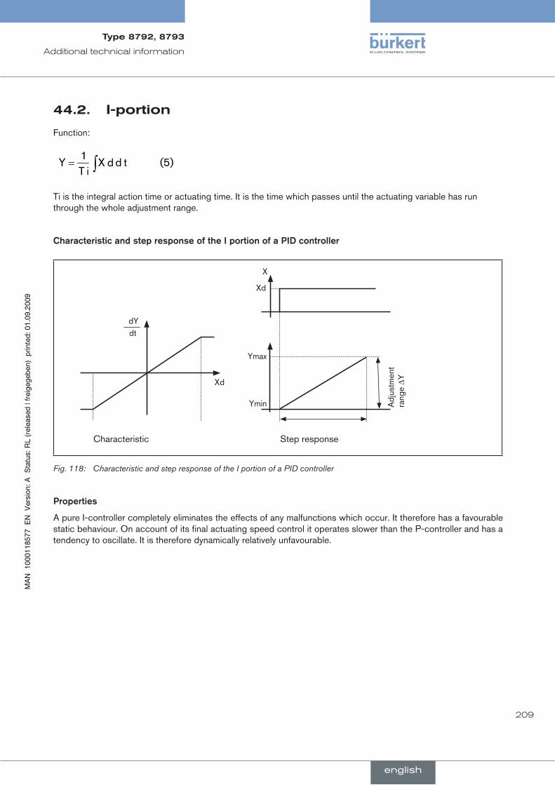
209
Additional technical information
i-portion44.2.
Function:
(5)t d d Xi T
1Y ∫=
Ti is the integral action time or actuating time. It is the time which passes until the actuating variable has run through the whole adjustment range.
Characteristic.and.step.response.of.the.I.portion.of.a.PID.controller
Characteristic Step response
X
Xd
Ymax
Ymin Adj
ustm
ent
rang
e ∆YXd
dYdt
Characteristic and step response of the I portion of a PID controllerFig. 118:
Properties
A pure I-controller completely eliminates the effects of any malfunctions which occur. It therefore has a favourable static behaviour. On account of its final actuating speed control it operates slower than the P-controller and has a tendency to oscillate. It is therefore dynamically relatively unfavourable.
english
Type8792,8793

210
Additional technical information
d-portion44.3.
Function:
(6)t dd X d
dK Y ⋅=
Kd is the derivative action coeffficient. The larger Kd is, the greater the D-effect is.
Characteristic.and.step.response.of.the.I.portion.of.a.PID.controller
Step response Ramp response
X
Xd
Y Y
X
t
t
Characteristic and step response of the D portion of a PID controllerFig. 119:
Properties
A controller with a D portion responds to changes in the control variable and may therefore reduce any control dif-ferences more quickly.
english
Type8792,8793

211
Additional technical information
superpositionofp,ianddportions44.4.
Function:
∫ ++⋅= (7)t dd X d
dK t d d Xi T
1d XpK Y
Where Kp · Ti = Tn and Kd/Kp = Tv the function of the pId controller is calculated according to the following equation:
∫ ++⋅= (8) )t dd X d
v Tt d d Xn T
1d X (pK Y
Kp Proportional coefficient / amplification factor
Tn Reset time (Time which is required to obtain an equally large change in the actuating variable by the I portion, as occurs due to the P portion)
Tv Derivative time (Time by which a certain actuating variable is reached earlier on account of the D portion than with a pure P-controller)
Step.response.and.ramp.response.of.the.PID.controller
Step response of the PID controller Ramp response of the PID controller
Xd
X
D-portion
X
Y
I-portion
P-portion
I-portion
P-portion
D-portion
Y
Reset time Tn Hold-back time Tv
Kp⋅Xd
t
t
t
t
Characteristic of step response and ramp response of PID controllerFig. 120:
english
Type8792,8793
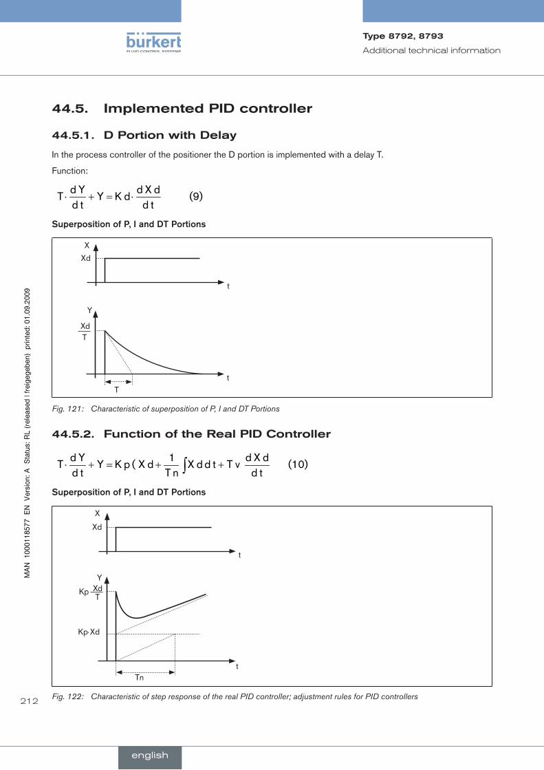
212
Additional technical information
implementedpidcontroller44.5.
dportionwithdelay44.5.1.
In the process controller of the positioner the D portion is implemented with a delay T.
Function:
(9)t dd X d
dK Yt dY d
T ⋅=+⋅
Superposition.of.P,.I.and.DT.Portions
X
Xd
Y
t
t
XdT
T
Characteristic of superposition of P, I and DT PortionsFig. 121:
functionoftherealpidcontroller44.5.2.
(10)t dd X d
v Tt d d Xn T
1d X ( pK Y
t dY d
T ∫ ++=+⋅
Superposition.of.P,.I.and.DT.Portions
X
Xd
Y
t
tTn
Kp⋅Xd
XdT
Kp
Characteristic of step response of the real PID controller; adjustment rules for PID controllersFig. 122:
english
Type8792,8793
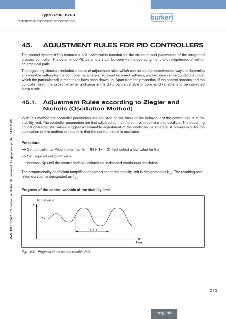
213
Additional technical information
adjusTMenTrulesfOrpidcOnTrOllers45.The control system 8793 features a self-optimization function for the structure and parameters of the integrated process controller. The determined PID parameters can be seen via the operating menu and re-optimized at will for an empirical path.
The regulatory literature includes a series of adjustment rules which can be used in experimental ways to determine a favourable setting for the controller parameters. To avoid incorrect settings, always observe the conditions under which the particular adjustment rules have been drawn up. Apart from the properties of the control process and the controller itself, the aspect whether a change in the disturbance variable or command variable is to be corrected plays a role.
adjustmentrulesaccordingtozieglerand45.1.nichols(OscillationMethod)
With this method the controller parameters are adjusted on the basis of the behaviour of the control circuit at the stability limit. The controller parameters are first adjusted so that the control circuit starts to oscillate. The occurring critical characteristic values suggest a favourable adjustment of the controller parameters. A prerequisite for the application of this method of course is that the control circuit is oscillated.
Procedure
Set controller as P-controller (i.e. Tn = 999, Tv = 0), first select a low value for Kp →Set required set-point value →Increase Kp until the control variable initiates an undamped continuous oscillation. →
The proportionality coefficient (amplification factor) set at the stability limit is designated as Kkrit. The resulting oscil-lation duration is designated as Tkrit.
Progress.of.the.control.variable.at.the.stability.limit
X
Time
Tkrit t
Actual value
Progress of the control variable PIDFig. 123:
english
Type8792,8793
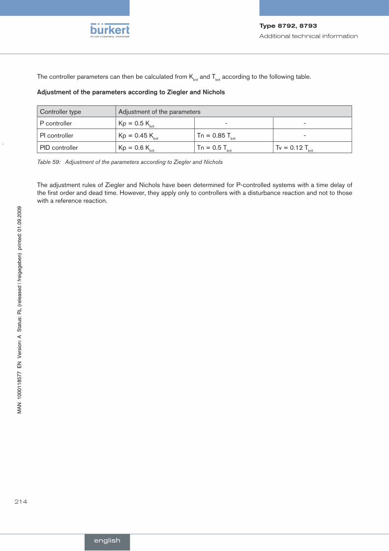
214
Additional technical information
The controller parameters can then be calculated from Kkrit and Tkrit according to the following table.
Adjustment.of.the.parameters.according.to.ziegler.and.nichols
Controller type Adjustment of the parameters
P controller Kp = 0.5 Kkrit - -
PI controller Kp = 0.45 Kkrit Tn = 0.85 Tkrit -
PID controller Kp = 0.6 Kkrit Tn = 0.5 Tkrit Tv = 0.12 Tkrit
Adjustment of the parameters according to Ziegler and NicholsTable 59:
The adjustment rules of Ziegler and Nichols have been determined for P-controlled systems with a time delay of the first order and dead time. However, they apply only to controllers with a disturbance reaction and not to those with a reference reaction.
english
Type8792,8793
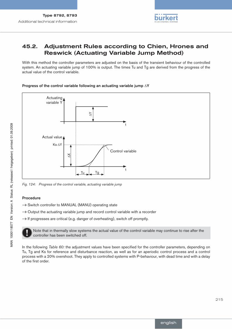
215
Additional technical information
adjustmentrulesaccordingtochien,hronesand45.2.reswick(actuatingvariablejumpMethod)
With this method the controller parameters are adjusted on the basis of the transient behaviour of the controlled system. An actuating variable jump of 100% is output. The times Tu and Tg are derived from the progress of the actual value of the control variable.
Progress.of.the.control.variable.following.an.actuating.variable.jump.∆Y
Actuating variable Y
Ks⋅∆Y
Actual value
∆X
Tu Tg
Control variable
t
∆Y
t
Progress of the control variable, actuating variable jumpFig. 124:
Procedure
Switch controller to MANUAL (MANU) operating state →Output the actuating variable jump and record control variable with a recorder →If progresses are critical (e.g. danger of overheating), switch off promptly. →
Note that in thermally slow systems the actual value of the control variable may continue to rise after the controller has been switched off.
In the following Table 60: the adjustment values have been specified for the controller parameters, depending on Tu, Tg and Ks for reference and disturbance reaction, as well as for an aperiodic control process and a control process with a 20% overshoot. They apply to controlled systems with P-behaviour, with dead time and with a delay of the first order.
english
Type8792,8793
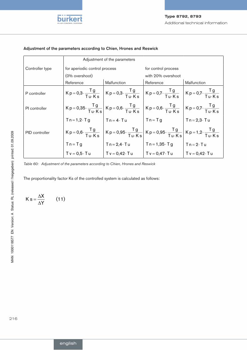
216
Additional technical information
Adjustment.of.the.parameters.according.to.Chien,.hrones.and.reswick
Adjustment of the parameters
Controller type for aperiodic control process
(0% overshoot)
for control process
with 20% overshoot
Reference Malfunction Reference Malfunction
P controllersK u T
g T30pK
⋅⋅= ,
sK u Tg T
30pK ⋅
⋅= ,sK u T
g T70pK
⋅⋅= ,
sK u Tg T
70pK ⋅
⋅= ,
PI controllersK u T
g T0,35pK
⋅⋅=
sK u Tg T
0,6pK ⋅
⋅=sK u T
g T0,6pK
⋅⋅=
sK u Tg T
70pK ⋅
⋅= ,
g T1,2n T ⋅= u T4n T ⋅= g Tn T = u T2,3n T ⋅=
PID controllersK u T
g T0,6pK
⋅⋅=
sK u Tg T
0,95pK ⋅
⋅=sK u T
g T0,95pK
⋅⋅=
sK u Tg T
1,2pK ⋅
⋅=
g Tn T = u T2,4n T ⋅= g T1,35n T ⋅= u T2n T ⋅=
u T0,5v T ⋅= u T0,42v T ⋅= u T0,47v T ⋅= u T0,42v T ⋅=
Table 60: Adjustment of the parameters according to Chien, Hrones and Reswick
The proportionality factor Ks of the controlled system is calculated as follows:
(11)YX
sK ∆∆
=
english
Type8792,8793
217
tables for customer-specific settings
conTenTs
46.. TABlE.FOr.YOur.SETTInGS.On.ThE.POSITIOn.COnTrOllEr...................................................................... 218
46.1.. Settings.of.the.Freely.Programmable.Characteristic.................................................................................... 218
47.. TABlE.FOr.YOur.SETTInGS.On.ThE.PrOCESS.COnTrOllEr.8793.......................................................... 219
47.1.. Set.Parameters.of.the.Process.Controller.......................................................................................................... 219
english
Type8792,8793

218
Tables for customer-specific settings
TaBlefOryOurseTTingsOnThe46.pOsiTiOncOnTrOller
46.1. settingsofthefreelyprogrammablecharacteristic
node (position set-point value as %)
valve stroke [%]
date: date: date: date:
0
5
10
15
20
25
30
35
40
45
50
55
60
65
70
75
80
85
90
95
100
english
Type8792,8793

219
Tables for customer-specific settings
47. TaBlefOryOurseTTingsOnTheprOcesscOnTrOller8793
setparametersoftheprocesscontroller47.1.
date: date: date: date:
kp
tn
tv
X0
dBnd
dp
pvmin
pvmax
Spmin
Spmax
unIt
k factor
fIlter
Inp
english
Type8792,8793

220
Tables for customer-specific settings
english
Type8792,8793

221
conTenTs
48.. MASTEr.CODE................................................................................................................................................................................ 222
master code
english
Type8792,8793
222
Master code
MasTercOde48.
Master code
3108
english
Type8792,8793

www.burkert.com
Related Documents