1 TUTORIAL PMSM Drive with Sensorless Control April 2017

Welcome message from author
This document is posted to help you gain knowledge. Please leave a comment to let me know what you think about it! Share it to your friends and learn new things together.
Transcript
1
TUTORIAL
PMSM Drive with Sensorless Control
April 2017
PMSM Drive with Sensorless Control
2
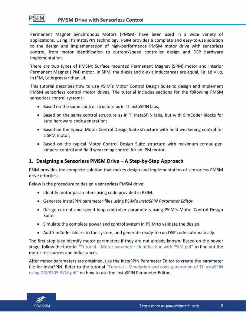
Permanent Magnet Synchronous Motors (PMSM) have been used in a wide variety of applications. Using TI’s InstaSPIN technology, PSIM provides a complete and easy‐to‐use solution to the design and implementation of high‐performance PMSM motor drive with sensorless control, from motor identification to current/speed controller design and DSP hardware implementation.
There are two types of PMSM: Surface mounted Permanent Magnet (SPM) motor and Interior Permanent Magnet (IPM) motor. In SPM, the d‐axis and q‐axis inductances are equal, i.e. Ld = Lq. In IPM, Lq is greater than Ld.
This tutorial describes how to use PSIM’s Motor Control Design Suite to design and implement PMSM sensorless control motor drives. The tutorial includes sections for the following PMSM sensorless control systems:
Based on the same control structure as in TI InstaSPIN labs;
Based on the same control structure as in TI InstaSPIN labs, but with SimCoder blocks for auto hardware code generation;
Based on the typical Motor Control Design Suite structure with field weakening control for a SPM motor;
Based on the typical Motor Control Design Suite structure with maximum torque‐per‐ampere control and field weakening control for an IPM motor.
1. Designing a Sensorless PMSM Drive – A Step‐by‐Step Approach
PSIM provides the complete solution that makes design and implementation of sensorless PMSM drive effortless.
Below is the procedure to design a sensorless PMSM drive:
Identify motor parameters using code provided in PSIM.
Generate InstaSPIN parameter files using PSIM’s InstaSPIN Parameter Editor.
Design current and speed loop controller parameters using PSIM’s Motor Control Design Suite.
Simulate the complete power and control system in PSIM to validate the design.
Add SimCoder blocks to the system, and generate ready‐to‐run DSP code automatically.
The first step is to identify motor parameters if they are not already known. Based on the power stage, follow the tutorial “Tutorial – Motor parameter identification with PSIM.pdf” to find out the motor resistances and inductances.
After motor parameters are obtained, use the InstaSPIN Parameter Editor to create the parameter file for InstaSPIN. Refer to the tutorial “Tutorial – Simulation and code generation of TI InstaSPIN using DRV8305 EVM.pdf” on how to use the InstaSPIN Parameter Editor.

PMSM Drive with Sensorless Control
3
With the InstaSPIN parameter file ready, use this tutorial to design PI controller parameters for current loop and speed loop.
With the controller parameters designed, apply them back into the system, and follow the procedure in the tutorial “Tutorial – Simulation and code generation of TI InstaSPIN using DRV8305 EVM.pdf” to perform overall system simulation and generate code for DSP hardware.
2. Motor Control Design Suite for PMSM Sensorless Control
The following new design templates are added to the Motor Control Design Suite:
‐ PMSM Sensorless Drive (InstaSPIN):
For PMSM sensorless drive (both SPM and IPM) using the InstaSPIN lab control structure
‐ PMSM Sensorless Drive (InstaSPIN SimCoder):
For PMSM sensorless drive (both SPM and IPM), with auto code generation, using the InstaSPIN lab control structure
‐ PMSM (SPM) Sensorless Drive (InstaSPIN):
For PMSM (SPM) sensorless drive using the Motor Control Design Suite control structure with field weakening control
‐ PMSM (IPM) Sensorless Drive (InstaSPIN):
For PMSM (IPM) sensorless drive using the Motor Control Design Suite control structure with maximum torque‐per‐ampere control and field weakening control
Note that all these templates use the InstaSPIN block as the sensorless estimator. Since the InstaSPIN block is part of the PIL Module, one must have the PIL Module in the PSIM license in order to run these templates.
The sections below describe how to use these templates.
3. PMSM Sensorless Drive with InstaSPIN Lab Control Structure
To design a sensorless PMSM drive with the same control structure as in TI InstaSPIN Lab 11, in PSIM, select Design Suites >> Motor Control Design Suite >> PMSM Sensorless Drive (InstaSPIN). After files are unpacked, the following schematic will appear.
On the left of the schematic is a list of parameters. These are the input parameters that need to be specified as inputs. Once all parameters are entered, click on Update Parameter File to obtain the new design parameters in the “parameters‐main.txt” file.
There is another parameter file called “InstaSPIN_params.txt”. This file is for the InstaSPIN block, and needs to be generated separately using PSIM’s InstaSPIN Parameter Editor. This file must be placed in the same folder as the schematic file.
The default settings of this template use the DRV8305 EVM hardware and the Anaheim BLDC motor BLY172S‐24V‐4000. If the hardware or the motor is different, the InstaSPIN parameter file “InstaSPIN_params.txt” needs to be regenerated and the input parameters need to be updated.
PMSM Drive with Sensorless Control
4
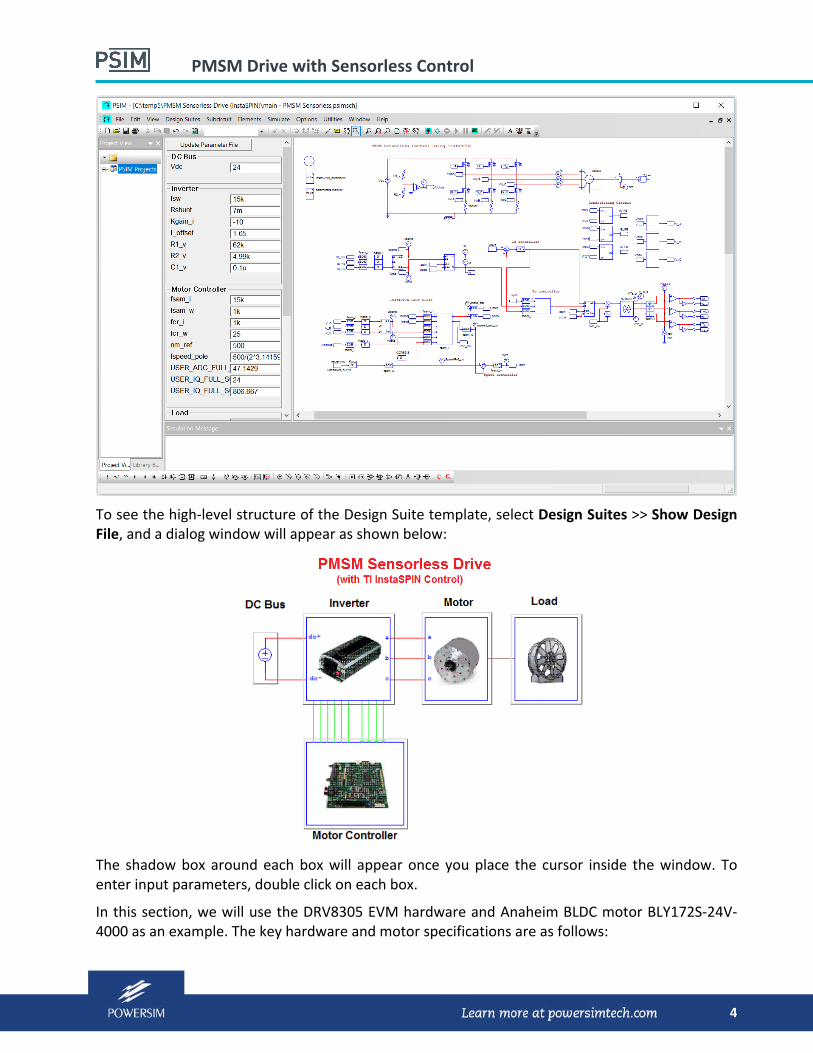
To see the high‐level structure of the Design Suite template, select Design Suites >> Show Design File, and a dialog window will appear as shown below:
The shadow box around each box will appear once you place the cursor inside the window. To enter input parameters, double click on each box.
In this section, we will use the DRV8305 EVM hardware and Anaheim BLDC motor BLY172S‐24V‐4000 as an example. The key hardware and motor specifications are as follows:

PMSM Drive with Sensorless Control
5
‐ Inverter: 24 Vdc, 15 kHz ‐ Motor: Anaheim motor BLY172S‐24V‐4000 (24 V, 11 A (peak), 55 W, 4000 rpm)
Based on the DRV8305 EVM hardware and the motor parameters, use the InstaSPIN Parameter Editor to obtain the parameter file “InstaSPIN_params.txt”. By default, the file “InstaSPIN_params.txt” in the schematic folder is for the DRV8305 EVM and the Anaheim motor BLY172S‐24V‐4000 already, and is ready to use. But if the hardware or the motor is different, this file needs to be re‐generated and placed in the schematic folder.
For the Design Suite template, enter the following parameters:
For DC Bus: Operating DC Bus Voltage (Vdc): 24
For Inverter: Shunt Resistance (Rshunt): 7m [current shunt resistor] Conditioning Circuit Gain (Kgain_i): ‐10 [current conditioning circuit gain] DC Offset (I_offset): 1.65 [current conditioning offset] Resistance R1 (R1_v): 62k [voltage divider resistance] Resistance R2 (R2_v): 4.99k [voltage divider resistance]
For Motor: Moment of Inertia (J_motor) 4.8u Shaft Time Constant (T_shaft) 0.05
For Load: Load Torque (T_load): 0 Load Moment of Inertia (J_load): 4u
For Motor Controller: Current Loop Sampling Freq. (fsam_i): 15k Speed Loop Sampling Freq. (fsam_w): 1k Current Loop Crossover Freq. (fcr_i): 1k [Used in current loop design] Speed Loop Crossover Freq. (fcr_w): 25 [Used in speed loop design] Motor Speed Reference (nm_ref): 500
Parameters Kgain_i and I_offset come from the current conditioning circuit. For DRV8305 EVM, the gain Kgain is ‐10., and it can be changed by adjusting the op. amp. feedback resistance.
Parameters R1_v and R2_v come from the voltage divider circuit in the DRV8305 EVM hardware.
There are several input and InstaSPIN parameters that have noticeable impact on the control performance, and need special attention when defining them:
‐ Maximum motor current USER_MOTOR_MAX_CURRENT ‐ Maximum motor speed ‐ Voltage feedback filter frequency USER_VOLTAGE_FILTER_POLE_Hz ‐ Speed feedback internal filter frequency USER_SPEED_POLE_rps ‐ Current loop crossover frequency fcr_i ‐ Speed loop crossover frequency fcr_w
PMSM Drive with Sensorless Control
6
The maximum motor current determines the current loop controller limit.
The maximum motor speed affects the IQ full scale frequency USER_IQ_FULL_SCALE_FREQ_Hz.
The filter frequency of the voltage feedback, USER_VOLTAGE_FILTER_POLE_Hz, together with the voltage divider resistances R1_v and R2_v, determines the capacitance C1_v. The filter frequency needs to be selected carefully for the InstaSPIN sensorless control algorithm to work. It must be less than the IQ full scale frequency USER_IQ_FULL_SCALE_FREQ_Hz.
The parameter USER_SPEED_POLE_rps, in rad/sec, is the frequency of the 1st‐order low‐pass filter internal to the InstaSPIN block. A recommended range of USER_SPEED_POLE_rps is from 100 to 500 rad/sec. (or 15.9 to 79.6 Hz). When selecting the speed loop crossover frequency fcr_w, make sure that it is lower than half of this filter frequency. If the speed loop response is not fast enough, increase the values of USER_SPEED_POLE_rps and fcr_w.
For the current loop, a good starting point of the current loop crossover frequency fcr_i is around 1/10 of the current loop sampling frequency fsam_i.
With the correct InstaSPIN parameter file, after all input parameters are entered in the parameter panel, click on Update Parameter File. Current loop PI controller parameters Kpi_d, Tpi_d, Kpi_q, Tpi_q and the speed loop PI controller parameters Kpi_w and Tpi_w will be designed automatically. In this case, the designed parameters are:
Kpi_d = 4.02 Tpi_d = 0.0016 Kpi_q = 4.02 Tpi_q = 0.0016 Kpi_w = 2.63 Tpi_w = 0.0175
The current loops have a phase margin of 86°, and the speed loop has a phase margin of 50°.
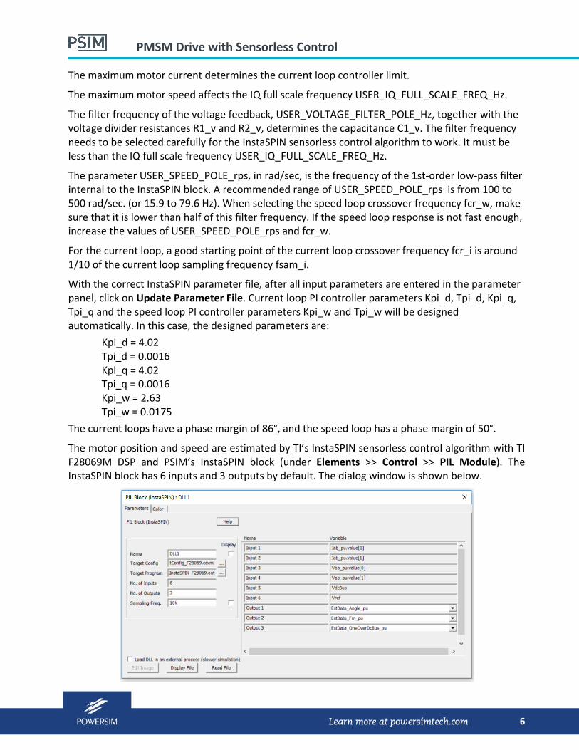
The motor position and speed are estimated by TI’s InstaSPIN sensorless control algorithm with TI F28069M DSP and PSIM’s InstaSPIN block (under Elements >> Control >> PIL Module). The InstaSPIN block has 6 inputs and 3 outputs by default. The dialog window is shown below.

PMSM Drive with Sensorless Control
7
The number of inputs is fixed, while the number of outputs can be changed. All inputs are in per unit, and the data format is IQ24.
The InstaSPIN block requires additional parameters, and these parameters are defined in a parameter file called “InstaSPIN_params.txt”. The file name is hard coded, and it cannot be changed. This file must be in the same folder as the schematic file.
There are many parameters that need to be defined and calculated for InstaSPIN, based on motor parameters, inverter operating conditions, and voltage and current sensing circuits. To ease the process of preparing the parameter file, PSIM provides an InstaSPIN Parameter Editor to help users quickly generate and modify the required “InstaSPIN_params.txt” file. Refer to “Tutorial – Simulation and code generation of TI InstaSPIN using DRV8305 EVM.pdf” for more details.
To run simulation, connect a F28069M hardware to the computer, and select Run Simulation. Refer to the same tutorial above for more details.
Simulation results from this example are shown below. The top trace shows the motor speed with the reference set to 500 rpm. The middle traces show the motor currents, and the bottom trace shows the motor torque.
0
-200
200
400
600
800
nm
0
-2
-4
-6
2
4
6Ia Ib Ic
0 0.02 0.04 0.06 0.08 0.1
Time (s)
0
-0.05
0.05
0.1
0.15
0.2
Tem_PMSM32
Speed (rpm)
Motor currents
Torque
PMSM Drive with Sensorless Control
8
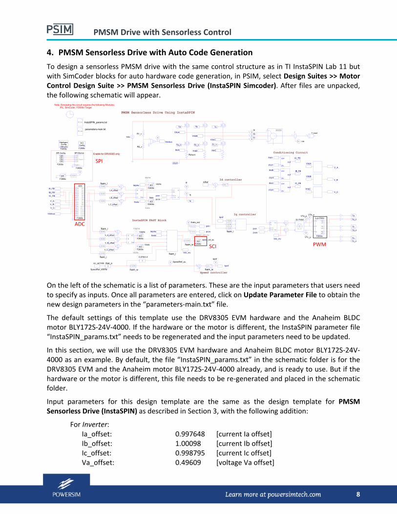
4. PMSM Sensorless Drive with Auto Code Generation
To design a sensorless PMSM drive with the same control structure as in TI InstaSPIN Lab 11 but with SimCoder blocks for auto hardware code generation, in PSIM, select Design Suites >> Motor Control Design Suite >> PMSM Sensorless Drive (InstaSPIN Simcoder). After files are unpacked, the following schematic will appear.
Vdc
Rshunt
PMSM Sensorless Drive Using InstaSPIN
Ta
Ta_n
Tb
Tb_n
Tc
Tc_n
IhbA IhbB IhbC
ITOT
VhbA
VhbB
VhbC
R1_v
R2_v
V
AIa
AIb
AIc
PMSM
V theta_est
Vdcbus
in+
out
in-
IhbA
ITOT
in+
out
in-
in+
out
in-ITOT
ITOT
IhbB
IhbC
VhbA
VhbB
VhbC
IA_FB
IC_FB
V_A
V_B
V_C
IB_FB
Vspeed_est_pu
V SpeedRef_pu
ZOH
fsam_w
ZOH
b
a
c
al
be
b
a
c
al
be
V
Ialpha
V
Ibeta
VValpha
VVbeta
sinu
cosu
VVTa_p V
VTb_p
V
VTc_p
V
Iqref
psin
pcos
psin
pcos
V
id
V iq
ZOH
fsam_w
K
0.275/3.3
KKwr_s
InstaSPIN_params.txt
nm_ref/1000
SpeedRef_KRPM
IdRef
psin
pcos
Id controller
Iq controller
Speed controller
Conditioning Circuit
InstaSPIN FAST Block
Ialpha
Ibeta
Vdc_inv
Vdc_inv
Iqref
Iqref
Ialpha
Ibeta
ZOH
ZOH
fsam_i
fsam_i
albe
sincos
d
q
zPI
File
nm
1 T_load
zPI
fsam_w
d alq
besincos
SV PWM
Iq
parameters-main.txt
File
Ta
Ta_n
Tb
Tb_n
Tc
Tc_n
u
v
w
F2806x
wpwn
vn
unup
vp
3-ph PWM
ZOHfsam_i
ZOH
ZOH
ZOHfsam_i
ZOH
ZOH
IA_FB
IB_FB
IC_FB
V_A
V_B
V_C
Vdcbus
ZOH
fsam_i
ADCA0
B7
A1A2A3A4A5A6A7B0B1B2B3B4B5B6
D0
D15
D1D2D3D4D5D6D7D8D9D10D11D12D13D14
F2806x
I_A_offset
I_B_offset
I_C_offset
V_A_offset
V_B_offset
V_C_offset
ConfigSCI
F2806x
CS0CS1CS2CS3
F2806x
SPI ConfigCS0CS1CS2CS3
Sync
Intr
SPI Device
F2806x
F2806x
SPIin
V
ZOH
Enable for DRV8305 only
F2806x
SCIout Ialpha
F2806x
SCIout
Ibeta
F2806x
SCIout
Valpha
F2806x
SCIout Vbeta F2806x
SCIout speed_est_pu
Note: Simulating this circuit requires the following Modules: PIL, SimCoder, F2806x Target
HardwareConfig
(100-pin)F2806x
On the left of the schematic is a list of parameters. These are the input parameters that users need to specify as inputs. Once all parameters are entered, click on Update Parameter File to obtain the new design parameters in the “parameters‐main.txt” file.
The default settings of this template use the DRV8305 EVM hardware and the Anaheim BLDC motor BLY172S‐24V‐4000. If the hardware or the motor is different, the InstaSPIN parameter file “InstaSPIN_params.txt” needs to be regenerated and the input parameters need to be updated.
In this section, we will use the DRV8305 EVM hardware and Anaheim BLDC motor BLY172S‐24V‐4000 as an example. By default, the file “InstaSPIN_params.txt” in the schematic folder is for the DRV8305 EVM and the Anaheim motor BLY172S‐24V‐4000 already, and is ready to use. But if the hardware or the motor is different, this file needs to be re‐generated and placed in the schematic folder.
Input parameters for this design template are the same as the design template for PMSM Sensorless Drive (InstaSPIN) as described in Section 3, with the following addition:
For Inverter: Ia_offset: 0.997648 [current Ia offset] Ib_offset: 1.00098 [current Ib offset] Ic_offset: 0.998795 [current Ic offset] Va_offset: 0.49609 [voltage Va offset]
ADC
PWM
SPI
SCI

PMSM Drive with Sensorless Control
9
Vb_Offset: 0.4954 [voltage Vb offset] Vc_Offset: 0.4964 [voltage Vc offset]
These are the offsets measured from the hardware circuit.
To perform auto code generation, ADC, PWM, SCI, and SPI blocks, as highlighted in red boxes, are added in the circuit. They simulate the functions of the corresponding F28069 hardware peripheral blocks. SCI blocks are used to display DSP waveforms in real time, and SPI blocks are used to set the configurations in the DRV8305 chip.
Proper settings of ADC, PWM, SCI and SPI blocks in the circuit are required for the simulation and code generation. For more information on how to generate code and run on F2806x DSP, refer to “Tutorial – Simulation and code generation of TI InstaSPIN using DRV8305 EVM.pdf” for more details. For more information on how to use SCI for real‐time waveform display, refer to “Tutorial – Using SCI for waveform monitoring.pdf”.
With the default parameter settings, the InstaSPIN parameters and the current loop/speed loop PI parameters will be the same as in Section 3. The simulation results are also the same.

PMSM Drive with Sensorless Control
10
5. PMSM (SPM) Sensorless Drive with Field Weakening Control
PSIM offers a generic PMSM (SPM) sensorless drive platform based on the advanced Motor Control Design Suite structure with field weakening control.
To design a sensorless PMSM drive based on the Motor Control Design Suite structure for a SPM motor, in PSIM, select Design Suites >> Motor Control Design Suite >> PMSM (SPM) Sensorless Drive (InstaSPIN). After files are unpacked, the following schematic will appear.
Vdc
PMSM (SPM) Sensorless Drive Using InstaSPIN
Ta
Ta_n
Tb
Tb_n
Tc
Tc_n
VhbA
VhbB
VhbC
AIa
AIb
AIc
PMSM
V theta_est
ZOHfsam_i
ZOH
ZOH
ZOHfsam_i
ZOH
ZOH
V_A
V_B
V_C
VhbA
VhbB
VhbC
V_A
V_B
V_C
V speed_est_puZOH
fsam_w
b
a
c
al
be
b
a
c
al
be
V
Ialpha
V
Ibeta
VValpha
VVbeta
sinu
cosu
psin
pcos
V
id
V iq
File
ZOH
fsam_i
KKadc_v
K
0.275/3.3
KKadc_i
K
K
K
Kadc_v
K
K
K
Kwr_s
InstaSPIN_params.txt
SpeedRef_KRPM
nm_ref/1000
psin
pcos
Conditioning Circuit
InstaSPIN FAST Block
Ialpha
Ibeta
Vdc_inv
Ialpha
Ibeta
ZOH
fsam_i
ZOH
ZOH
ZOH
ZOH
ZOH
fsam_iVdc_pu
V
Wm_ref_pu Speed Control
Motor Controller
Iq_pu
Id_pu
flag_FW flag_FW
Field Weakening Control
Dynamic Torque Limit Control Current Control
1z
fsam_w
I_max/Ib
-I_max/Ib
VS_FW
K
Tb/(K_TA*Ib) SVPWM
Vtri*2
180
fsw
Vdc_pu
Wm_pu
Wm_puVdc_pu
Wm_pu
0 ZOH
fsam_i
ZOH
fsam_i
ZOH
fsam_i
ZOH
fsam_i
ZOHfsam_i
1z
fsam_i
1z
fsam_i
1z
fsam_i
VVma
parameters-main.txt
Ki_sen
Isa
Isb
Isc
nm
1T_load
Wm_pu
Tc_n
Tc
Tb_n
Tb
Ta_n
Ta
Group 1
Dynamic Torque
Id
Iq
Vdc
Wm
Tcmd FW
Te
Wm_th
Is
Wm
Id
Iq
Field Weakening (SPM)
Vdc
albe
sincos
d
qIq_pu
Id_pu
File
Isa
IsbIsc
R1_v
R2_v
V
Vdcbus
Vdcbus
Vdcbus
psin
pcos
d alq
besincos
SV PWM
Note: Simulating this circuit requires the PIL Module.
The default settings of this template use the DRV8305 EVM hardware and the Anaheim BLDC motor BLY172S‐24V‐4000. If the hardware or the motor is different, the InstaSPIN parameter file “InstaSPIN_params.txt” needs to be regenerated and the input parameters need to be updated.
On the left of the schematic is a list of parameters. These are the input parameters that users need to specify as inputs. Once all parameters are entered, click on Update Parameter File to obtain the new design parameters in the “parameters‐main.txt” file.
The Motor Control Design Suite control structure shown above is different from the one in TI InstaSPIN Lab 11. There are two advanced control blocks added to the circuit: Dynamic Torque
PMSM Drive with Sensorless Control
11
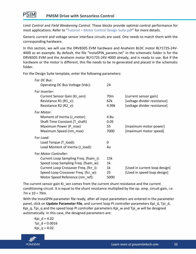
Limit Control and Field Weakening Control. These blocks provide optimal control performance for most applications. Refer to “Tutorial – Motor Control Design Suite.pdf” for more details.
Generic current and voltage sensor interface circuits are used. One needs to match them with the corresponding hardware.
In this section, we will use the DRV8305 EVM hardware and Anaheim BLDC motor BLY172S‐24V‐4000 as an example. By default, the file “InstaSPIN_params.txt” in the schematic folder is for the DRV8305 EVM and the Anaheim motor BLY172S‐24V‐4000 already, and is ready to use. But if the hardware or the motor is different, this file needs to be re‐generated and placed in the schematic folder.
For the Design Suite template, enter the following parameters:
For DC Bus: Operating DC Bus Voltage (Vdc): 24
For Inverter: Current Sensor Gain (Ki_sen): 70m [current sensor gain] Resistance R1 (R1_v): 62k [voltage divider resistance] Resistance R2 (R2_v): 4.99k [voltage divider resistance]
For Motor: Moment of Inertia (J_motor) 4.8u Shaft Time Constant (T_shaft) 0.05 Maximum Power (P_max) 55 [maximum motor power] Maximum Speed (nm_max) 7000 [maximum motor speed]
For Load: Load Torque (T_load): 0 Load Moment of Inertia (J_load): 4u
For Motor Controller: Current Loop Sampling Freq. (fsam_i): 15k Speed Loop Sampling Freq. (fsam_w): 1k Current Loop Crossover Freq. (fcr_i): 1k [Used in current loop design] Speed Loop Crossover Freq. (fcr_w): 25 [Used in speed loop design] Motor Speed Reference (nm_ref): 5000
The current sensor gain Ki_sen comes from the current shunt resistance and the current conditioning circuit. It is equal to the shunt resistance multiplied by the op. amp. circuit gain, i.e. 7m x 10 = 70m.
With the InstaSPIN parameter file ready, after all input parameters are entered in the parameter panel, click on Update Parameter File, and current loop PI controller parameters Kpi_d, Tpi_d, Kpi_q, Tpi_q and the speed loop PI controller parameters Kpi_w and Tpi_w will be designed automatically. In this case, the designed parameters are:
Kpi_d = 4.02 Tpi_d = 0.0016 Kpi_q = 4.02

PMSM Drive with Sensorless Control
12
Tpi_q = 0.0016 Kpi_w = 11.49 Tpi_w = 0.0175
To run the simulation, connect a F28069M hardware to the computer, and select Run Simulation.
The simulation results are shown below. The first trace from the trop is the motor speed, with the reference set to 5000 rpm. In the initial speed ramp up period, the control operates in the maximum torque mode, with the motor currents (the 2nd traces from the top) limited by the maximum motor current of 5A. As the speed reaches the reference, the torque is reduced and is settled to the steady state after a short transient. In the whole duration, the control does not enter into the field weakening control mode, as indicated by the field weakening flag (the bottom trace).
0K
-1K
1K
2K
3K
4K
5K
6K
nm
0
-2
-4
-6
2
4
6
Ia Ib Ic
0
-0.025
0.025
0.05
0.075
0.1
0.125
0.15
Tem_PMSM32
0 0.02 0.04 0.06 0.08 0.1 0.12 0.14
Time (s)
0
0.2
0.4
0.6
0.8
1
S_FW
Speed (rpm)
Motor currents
Torque
FW flag
PMSM Drive with Sensorless Control
13
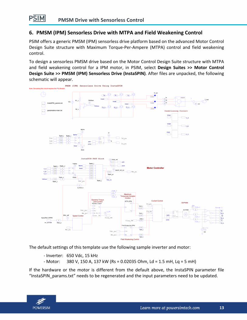
6. PMSM (IPM) Sensorless Drive with MTPA and Field Weakening Control
PSIM offers a generic PMSM (IPM) sensorless drive platform based on the advanced Motor Control Design Suite structure with Maximum Torque‐Per‐Ampere (MTPA) control and field weakening control.
To design a sensorless PMSM drive based on the Motor Control Design Suite structure with MTPA and field weakening control for a IPM motor, in PSIM, select Design Suites >> Motor Control Design Suite >> PMSM (IPM) Sensorless Drive (InstaSPIN). After files are unpacked, the following schematic will appear.
Vdc
PMSM (IPM) Sensorless Drive Using InstaSPIN
Ta
Ta_n
Tb
Tb_n
Tc
Tc_n
VhbA
VhbB
VhbC
AIa
AIb
AIc
PMSM
V theta_est
ZOHfsam_i
ZOH
ZOH
ZOHfsam_i
ZOH
ZOH
V_A
V_B
V_C
VhbA
VhbB
VhbC
V_A
V_B
V_C
V speed_est_puZOH
fsam_w
b
a
c
al
be
b
a
c
al
be
V
Ialpha
V
Ibeta
VValpha
VVbeta
sinu
cosu
psin
pcos
V
id
V iq
File
ZOH
fsam_i
KKadc_v
K
0.275/3.3
KKadc_i
K
K
K
Kadc_v
K
K
InstaSPIN_params.txt
SpeedRef_KRPM
nm_ref/1000
psin
pcos
Conditioning Circuit
InstaSPIN FAST Block
Ialpha
Ibeta
Vdc_inv
Ialpha
Ibeta
ZOH
fsam_i
ZOH
ZOH
ZOH
ZOH
ZOH
fsam_iVdc_pu
V
Wm_ref Speed Control
Motor Controller
Iq_pu
Id_pu
flag_FW
flag_FW
Field Weakening Control
Dynamic Torque Limit Control Current Control
1z
fsam_w
VS_FW
SVPWM
fswVtri*2
180
Vdc_pu
Wm_pu
Wm_puVdc_pu
Wm_pu
ZOH
fsam_i
ZOH
fsam_i
ZOH
fsam_i
ZOH
fsam_i
ZOHfsam_i
1z
fsam_i
1z
fsam_i
1z
fsam_i
VVma
parameters-main.txt
Ki_sen
Isa
Isb
Isc
nm
1T_load
Wm_pu
Tc_n
Tc
Tb_n
Tb
Ta_n
Ta
Group 1
Iq_pu
Id_pu
File
Isa
IsbIsc
R1_v
R2_v
V
Vdcbus
Vdcbus
Vdcbus
K
Kwr_s
psin
pcos
1z
fsam_w
MaximumTorque-per-Ampere
Control
Note: Simulating this circuit requires the PIL Module.
albe
sincos
d
q
MTPA (IPM)
Is
Iq
IdDynamic Torque
Id
Iq
Vdc
Wm
Tcmd FW
Is
Wm_th
Is
Wm
Id
Iq
Field Weakening (IPM)
Vdc
d alq
besincos
SV PWM
The default settings of this template use the following sample inverter and motor:
‐ Inverter: 650 Vdc, 15 kHz ‐ Motor: 380 V, 150 A, 137 kW (Rs = 0.02035 Ohm, Ld = 1.5 mH, Lq = 5 mH)
If the hardware or the motor is different from the default above, the InstaSPIN parameter file “InstaSPIN_params.txt” needs to be regenerated and the input parameters need to be updated.

PMSM Drive with Sensorless Control
14
On the left of the schematic is a list of parameters. These are the input parameters that users need to specify as inputs. Once all parameters are entered, click on Update Parameter File to obtain the new design parameters in “parameters‐main.txt” file.
The Motor Control Design Suite control structure shown above is different from the one in TI InstaSPIN Lab 11. There are three advanced control blocks added to the circuit: Dynamic Torque Limit Control, Maximum‐Torque‐per‐Ampere Control, and Field Weakening Control. These blocks provide optimal control performance in most applications. Please refer to “Tutorial – Motor Control Design Suite.pdf” for more details.
Generic current and voltage sensor interface circuits are provided. One needs to match them with the corresponding hardware.
In this example, we will use the default inverter and motor. By default, the file “InstaSPIN_params.txt” in the schematic folder is for the default hardware and motor already, and is ready to use. But if the hardware or the motor is different, this file needs to be re‐generated and placed in the schematic folder.
For the Design Suite template, enter the following parameters:
For DC Bus: Operating DC Bus Voltage (Vdc): 650
For Inverter: Current Sensor Gain (Ki_sen): 8.25m [current sensor gain] Resistance R1 (R1_v): 500k [voltage divider resistance] Resistance R2 (R2_v): 2.55k [voltage divider resistance]
For Motor: Moment of Inertia (J_motor) 0.206 Shaft Time Constant (T_shaft) 100 Maximum Power (P_max) 137k Maximum Speed (nm_max) 5000
For Load: Load Torque (T_load): 50 Load Moment of Inertia (J_load): 0.01
For Motor Controller: Current Loop Sampling Freq. (fsam_i): 15k Speed Loop Sampling Freq. (fsam_w): 1k Current Loop Crossover Freq. (fcr_i): 1k [Used in current loop design] Speed Loop Crossover Freq. (fcr_w): 10 [Used in speed loop design] Motor Speed Reference (nm_ref): 3000
Parameters R1_v and R2_v come from the voltage divider in the hardware circuit.
One should follow the same design guideline as described in Section 3 when selecting the current and speed loop crossover frequencies and other parameters.
PMSM Drive with Sensorless Control
15
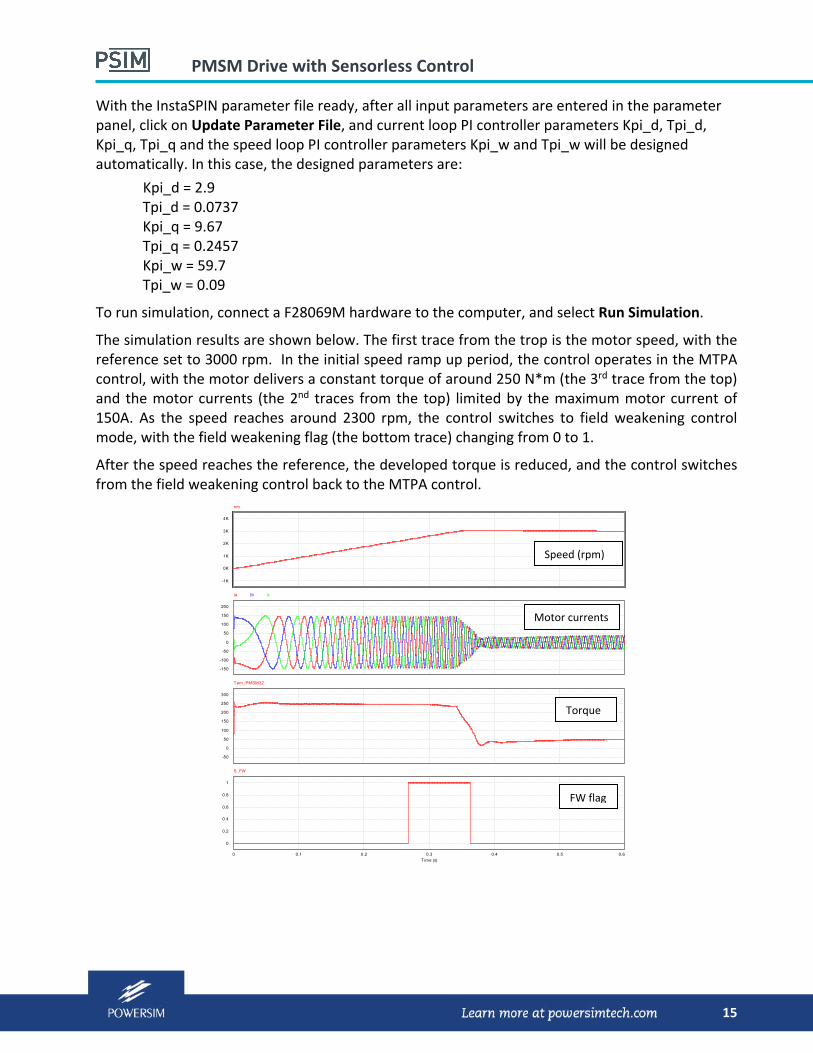
With the InstaSPIN parameter file ready, after all input parameters are entered in the parameter panel, click on Update Parameter File, and current loop PI controller parameters Kpi_d, Tpi_d, Kpi_q, Tpi_q and the speed loop PI controller parameters Kpi_w and Tpi_w will be designed automatically. In this case, the designed parameters are:
Kpi_d = 2.9 Tpi_d = 0.0737 Kpi_q = 9.67 Tpi_q = 0.2457 Kpi_w = 59.7 Tpi_w = 0.09
To run simulation, connect a F28069M hardware to the computer, and select Run Simulation.
The simulation results are shown below. The first trace from the trop is the motor speed, with the reference set to 3000 rpm. In the initial speed ramp up period, the control operates in the MTPA control, with the motor delivers a constant torque of around 250 N*m (the 3rd trace from the top) and the motor currents (the 2nd traces from the top) limited by the maximum motor current of 150A. As the speed reaches around 2300 rpm, the control switches to field weakening control mode, with the field weakening flag (the bottom trace) changing from 0 to 1.
After the speed reaches the reference, the developed torque is reduced, and the control switches from the field weakening control back to the MTPA control.
0K
-1K
1K
2K
3K
4K
nm
0
-50
-100
-150
50
100
150
200
Ia Ib Ic
0
-50
50
100
150
200
250
300
Tem_PMSM32
0 0.1 0.2 0.3 0.4 0.5 0.6
Time (s)
0
0.2
0.4
0.6
0.8
1
S_FW
Speed (rpm)
Motor currents
Torque
FW flag
PMSM Drive with Sensorless Control
16
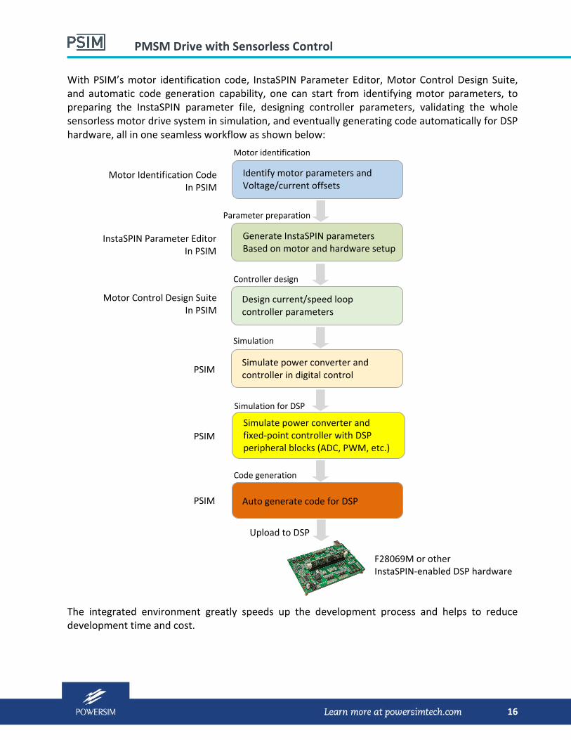
With PSIM’s motor identification code, InstaSPIN Parameter Editor, Motor Control Design Suite, and automatic code generation capability, one can start from identifying motor parameters, to preparing the InstaSPIN parameter file, designing controller parameters, validating the whole sensorless motor drive system in simulation, and eventually generating code automatically for DSP hardware, all in one seamless workflow as shown below:
The integrated environment greatly speeds up the development process and helps to reduce development time and cost.
Simulate power converter and controller in digital control
Simulate power converter and fixed‐point controller with DSP peripheral blocks (ADC, PWM, etc.)
Auto generate code for DSP
PSIM
PSIM
PSIM
Upload to DSP
F28069M or other InstaSPIN‐enabled DSP hardware
Simulation
Simulation for DSP
Code generation
Parameter preparation
Generate InstaSPIN parameters Based on motor and hardware setup
InstaSPIN Parameter Editor In PSIM
Motor identification
Motor Identification Code In PSIM
Identify motor parameters and Voltage/current offsets
Design current/speed loop controller parameters
Controller design
Motor Control Design Suite In PSIM
Related Documents