5 Sensorless Vector Control of Induction Motor Drive - A Model Based Approach Jogendra Singh Thongam 1 and Rachid Beguenane 2 1 Department of Renewable Energy Systems, STAS Inc., Chicoutimi, QC 2 Department of ECE, Royal Military College, Kingston, ON Canada 1. Introduction Induction machines are more rugged, compact, cheap and reliable in comparison to other machines used in similar applications. Vector controlled induction motor drive outperforms the dc motor drive because of higher transient current capability, increased speed range and lower rotor inertia. Sensors widely used in electric drives degrade the reliability of the system especially in hostile environments and require special attention to electrical noise. Moreover, it is difficult to mount sensors in certain applications in addition to extra expenses involved. Therefore, a lot of researches are underway to develop accurate speed estimation techniques. With sensorless vector control we have a decoupled control structure similar to that of a separately excited dc motor retaining the inherent ruggedness of the induction motor at the same time. Speed sensorless control technique first appeared in (Abbondante & Brennen, 1975). The commonly used methods for speed estimation are Model Reference Adaptive System (MRAS) (Schauder, 1992; Tajima & Hori, 1993; Peng & Fukao, 1994; Choy et al., 1996), Neural Networks (Simoes & Bose, 1995; Fodor et al., 1995; Ben-Brahim & Kudor, 1995; Kim et al., 2001; Toqeer & Bayindir, 2003; Haghgoeian et al., 2005), Extended Kalman Filter (EKF) (Kim et al.,1994, Comnac et al., 2001; Ma & Gui, 2002; Du et al., 1995; Thongam & Thoudam, 2004) and Nonlinear Observer (Bodson et al., 1995; Liu et al., 2001, Pappano et al., 1998). The aim of this chapter is to provide with a brief overview of high performance sensorless induction motor drive. There exist two approaches to speed estimation for sensorless control of induction machine: non model based approach and model based approach. The non model based technique tracks a machine anisotropy: either saturation for flux estimation or rotor slotting for rotor position estimation, whereas the model based technique rely mostly on back emf voltage associated with fundamental component excitation of the machine. Model-based observers are considered very well adapted for state estimation and allow, in most cases, a stability proof and a methodology to tune observer gains. Among the observers the reduced order observers are more frequently implemented than the full order ones as they don’t require heavy computations. Two sensorless vector control strategies using machine model-based estimation are presented in this chapter. www.intechopen.com

Welcome message from author
This document is posted to help you gain knowledge. Please leave a comment to let me know what you think about it! Share it to your friends and learn new things together.
Transcript
5
Sensorless Vector Control of Induction Motor Drive - A Model Based Approach
Jogendra Singh Thongam1 and Rachid Beguenane2 1Department of Renewable Energy Systems,
STAS Inc., Chicoutimi, QC 2Department of ECE, Royal Military College,
Kingston, ON Canada
1. Introduction
Induction machines are more rugged, compact, cheap and reliable in comparison to other machines used in similar applications. Vector controlled induction motor drive outperforms the dc motor drive because of higher transient current capability, increased speed range and lower rotor inertia. Sensors widely used in electric drives degrade the reliability of the system especially in hostile environments and require special attention to electrical noise. Moreover, it is difficult to mount sensors in certain applications in addition to extra expenses involved. Therefore, a lot of researches are underway to develop accurate speed estimation techniques. With sensorless vector control we have a decoupled control structure similar to that of a separately excited dc motor retaining the inherent ruggedness of the induction motor at the same time. Speed sensorless control technique first appeared in (Abbondante & Brennen, 1975). The commonly used methods for speed estimation are Model Reference Adaptive System (MRAS) (Schauder, 1992; Tajima & Hori, 1993; Peng & Fukao, 1994; Choy et al., 1996), Neural Networks (Simoes & Bose, 1995; Fodor et al., 1995; Ben-Brahim & Kudor, 1995; Kim et al., 2001; Toqeer & Bayindir, 2003; Haghgoeian et al., 2005), Extended Kalman Filter (EKF) (Kim et al.,1994, Comnac et al., 2001; Ma & Gui, 2002; Du et al., 1995; Thongam & Thoudam, 2004) and Nonlinear Observer (Bodson et al., 1995; Liu et al., 2001, Pappano et al., 1998). The aim of this chapter is to provide with a brief overview of high performance sensorless induction motor drive. There exist two approaches to speed estimation for sensorless control of induction machine: non model based approach and model based approach. The non model based technique tracks a machine anisotropy: either saturation for flux estimation or rotor slotting for rotor position estimation, whereas the model based technique rely mostly on back emf voltage associated with fundamental component excitation of the machine. Model-based observers are considered very well adapted for state estimation and allow, in most cases, a stability proof and a methodology to tune observer gains. Among the observers the reduced order observers are more frequently implemented than the full order ones as they don’t require heavy computations. Two sensorless vector control strategies using machine model-based estimation are presented in this chapter.
www.intechopen.com

Electric Machines and Drives
78
2. Speed estimation
Rotor speed has been considered as a constant by many researchers in speed estimation problem (Schauder, 1992; Tajima & Hori, 1993; Peng & Fukao, 1994; Kim et al., 1994; Comnac et al., 2001; Ma & Gui, 2002; Du et al., 1995; Minami et al., 1991; Veleyez-Reyes & Verghese., 1992; Veleyez-Reyes et al., 1989). The idea is that the speed changes slowly compared to electrical variables. Adopting such an approach allowed speed estimation without requiring the knowledge of mechanical parameters of the drive system such as load torque, inertia etc. In (Schauder, 1992; Tajima & Hori, 1993; Peng & Fukao, 1994) speed was estimated using model reference adaptive system considering it as an unknown constant parameter. In (Kim et al., 1994; Comnac et al., 2001; Ma & Gui, 2002; Du et al., 1995) the speed was considered as an unknown constant state of the machine and extended kalman filter (EKF) was used to estimate it. Recursive least square estimation method was used in (Minami et al., 1991; Veleyez-Reyes & Verghese, 1992; Veleyez-Reyes et al., 1989) for speed estimation considering speed as an unknown constant parameter and found out the value of estimated speed that best fits the measured and calculated data in the dynamic equations of the motor. In this section we present a sensorless vector control strategy using machine model-based speed estimation (Thongam & Ouhrouche, 2007). The proposed method does not require taking derivative of the measured signals unlike that of (Peng & Fukao, 1994; Minami et al., 1991; Veleyez-Reyes & Verghese, 1992; Veleyez-Reyes et al., 1989). The method is also simpler to implement than implementing EKF. In this method the model of the motor used for estimation is derived by introducing a new variable which is a function of rotor flux and speed assuming that rotor speed varies slowly in comparison to electrical states and hence its derivative can be conveniently equated to zero in the machine model used for estimation. The sensorless method presented here in this chapter is based on observing this new variable. A reduced order observer is implemented for estimating the new variable using which the rotor speed is estimated.
2.1 Induction machine model
The induction motor model in stationary stator reference frame α β− may be written in
vector matrix form as
11 12= +rr s
d
dtA A i
ψ ψ (1)
21 22 23s
r s s
d
dt= + +i
A A i A vψ (2)
where ( )11 r rR / L ω= − +A I J , ( )12 m r rL R / L=A I , ( ){ }21m
r rs r
LR / L
L Lωσ= −A I J ,
( ) ( ){ }2 222 / /s s r m s rR L R L L Lσ σ= − +A I , ( )23 1 s/ Lσ=A I ,
1 0
0 1
⎡ ⎤= ⎢ ⎥⎣ ⎦I , 0 1
1 0
−⎡ ⎤= ⎢ ⎥⎣ ⎦J ,
T
r r rα βψ ψ⎡ ⎤= ⎣ ⎦ψ is the rotor flux, T
s s si iα β⎡ ⎤= ⎣ ⎦i is the stator current, T
s s sv vα β⎡ ⎤= ⎣ ⎦v is
the stator voltage and 21 /( )m s rL L Lσ = − is the leakage coefficient.
www.intechopen.com
Sensorless Vector Control of Induction Motor Drive - A Model Based Approach
79
Now, we introduce a new quantity into the motor model which when introduced will make the right hand side of conventional motor model given by equations (1) and (2) independent of the unknowns – the rotor flux and speed. Let’s define the new quantity as
11 r= −Z A ψ (3)
A new motor model is obtained after introducing the new quantity as given below:
12 14r
s
d
dt= +A i A Z
ψ (4)
22 23 24s
s s
d
dt= + +i
A i A v A Z (5)
32 34s
d
dt= +Z
A i A Z (6)
where 14 = −A I , ( ){ }24 /m s rL L Lσ=A I , ( ) ( )2 232 / /m r r m r rL R L L R Lω= −A I J and 34 11=A A .
2.2 Observer structure and speed estimation
The proposed speed estimation algorithm is based on observing the newly defined quantity which is a function of rotor flux and speed. Equation (5) and (6) are used for constructing a Gopinath’s reduced order observer (Gopinath, 1971) for estimating the newly defined quantity. The observer is as given below
32 34
ˆˆˆ s s
s
d dd
dt dt dt
⎛ ⎞= + + −⎜ ⎟⎜ ⎟⎝ ⎠i iZ
A i A Z G (7)
where 1 2
2 1
g g
g g
−⎡ ⎤= ⎢ ⎥⎣ ⎦G is the observer gain. Using equation (5) for ˆsd
dt
i the observer equation
becomes
32 34 22 23 24
ˆˆ ˆs
s s s
ddv
dt dt
⎛ ⎞= + + − − −⎜ ⎟⎝ ⎠iZ
A i A Z G A i A A Z (8)
The observer poles can be placed at the desired locations in the stable region of the complex plane by properly choosing the values of the elements of the G matrix. In order to avoid taking derivative of the stator current in the algorithm we introduce another new quantity
ˆs= −D Z Gi (9)
Finally, the observer is of the following form:
( ) ( )32 34 22 24 23 34 24s s
d
dt= + − − − + −F A A G GA GA G i GA v A GA D ` (10)
www.intechopen.com
Electric Machines and Drives
80
ˆs= +Z D Gi (11)
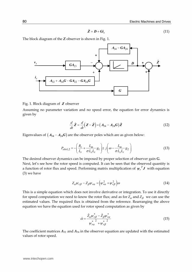
The block diagram of the Z observer is shown in Fig. 1.
Fig. 1. Block diagram of Z observer
Assuming no parameter variation and no speed error, the equation for error dynamics is given by
( ) ( )34 24ˆd d
dt dt= − = −Z Z Z A A G Z# # (12)
Eigenvalues of ( )34 24−A A G are the observer poles which are as given below:
1,2 1 2m mr
obsr s r s r
L LRP g j g
L L L L Lωσ σ
⎛ ⎞ ⎛ ⎞= − + ± −⎜ ⎟ ⎜ ⎟⎜ ⎟ ⎜ ⎟⎝ ⎠ ⎝ ⎠ (13)
The desired observer dynamics can be imposed by proper selection of observer gain G.
Next, let’s see how the rotor speed is computed. It can be seen that the observed quantity is
a function of rotor flux and speed. Performing matrix multiplication of Trψ J with equation
(3) we have
( )2 2r r r rZ Zα β β α α βψ ψ ψ ψ ω− = + (14)
This is a simple equation which does not involve derivative or integration. To use it directly
for speed computation we need to know the rotor flux; and as for Zα and Zβ we can use the
estimated values. The required flux is obtained from the reference. Rearranging the above
equation we have the equation used for rotor speed computation as given by
* *
2 2* *
ˆ ˆˆ
r r
r r
Z Zα β β αα βψ ψω ψ ψ
−=+
(15)
The coefficient matrices A32 and A34 in the observer equation are updated with the estimated values of rotor speed.
34 24−A GA
32 34 22 24+ − −A A G GA GA G
sv
si
G
_
+
+
+
+
Z 23GA
D
www.intechopen.com
Sensorless Vector Control of Induction Motor Drive - A Model Based Approach
81
It is to be noted here that the model of the motor used in implementing the observer
algorithm has been developed assuming that the derivative of the rotor speed is zero. It is
valid to make such an assumption since the dynamics of rotor speed is much slower than
that of electrical states. Moreover, such an assumption allows estimation without requiring
the knowledge of mechanical quantities of the drive such as load torque, inertia etc.
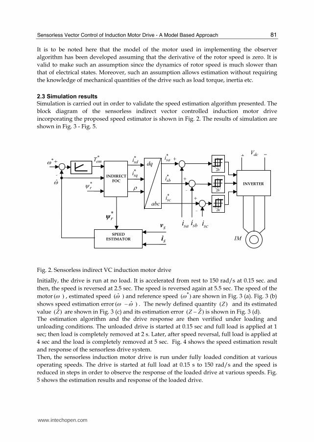
2.3 Simulation results
Simulation is carried out in order to validate the speed estimation algorithm presented. The
block diagram of the sensorless indirect vector controlled induction motor drive
incorporating the proposed speed estimator is shown in Fig. 2. The results of simulation are
shown in Fig. 3 - Fig. 5.
Fig. 2. Sensorless indirect VC induction motor drive
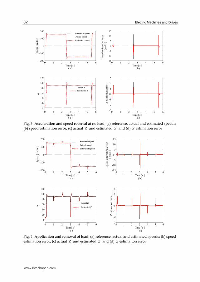
Initially, the drive is run at no load. It is accelerated from rest to 150 rad/s at 0.15 sec. and
then, the speed is reversed at 2.5 sec. The speed is reversed again at 5.5 sec. The speed of the
motor ( )ω , estimated speed ˆ( )ω and reference speed *( )ω are shown in Fig. 3 (a). Fig. 3 (b)
shows speed estimation error ˆ( )ω ω− . The newly defined quantity ( )Z and its estimated
value ˆ( )Z are shown in Fig. 3 (c) and its estimation error ˆ( )Z Z− is shown in Fig. 3 (d). The estimation algorithm and the drive response are then verified under loading and
unloading conditions. The unloaded drive is started at 0.15 sec and full load is applied at 1
sec; then load is completely removed at 2 s. Later, after speed reversal, full load is applied at
4 sec and the load is completely removed at 5 sec. Fig. 4 shows the speed estimation result
and response of the sensorless drive system.
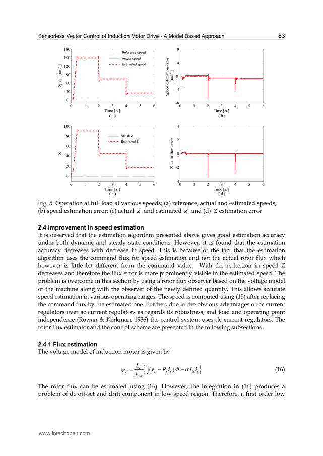
Then, the sensorless induction motor drive is run under fully loaded condition at various
operating speeds. The drive is started at full load at 0.15 s to 150 rad/s and the speed is
reduced in steps in order to observe the response of the loaded drive at various speeds. Fig.
5 shows the estimation results and response of the loaded drive.
dq
ω
sv
siSPEED
ESTIMATOR
*emT
*rψ
*rψ
INDIRECT
FOC
+_
*ω
sbi
*sdi
ρ*sqi
+
_
_
_
IM
INVERTER
+_
dcV
scisai
*sbi
*sci +
+
*sai
abc
2h
2h
2h
www.intechopen.com
Electric Machines and Drives
82
0 1 2 3 4 5 6-200
-100
0
100
200
Time [ s ] ( a )
Speed [
rad
/s ]
0 1 2 3 4 5 6-15
-10
-5
0
5
10
15
Time [ s ] ( b )
Sp
eed
est
imati
on
err
or
[
rad
/s ]
0 1 2 3 4 5 6
0
20
40
60
80
100
120
Time [ s ] ( c )
Z
0 1 2 3 4 5 6-3
-2
-1
0
1
2
3
Time [ s ] ( d )
Z e
stim
ati
on
err
or
Reference speed
Actual speed
Estimated speed
Actual Z
Estimated Z
Fig. 3. Acceleration and speed reversal at no load; (a) reference, actual and estimated speeds;
(b) speed estimation error; (c) actual Z and estimated Z and (d) Z estimation error
0 1 2 3 4 5 6-200
-100
0
100
200
Time [ s ] ( a )
Sp
eed
[ r
ad
/s ]
0 1 2 3 4 5 6-15
-10
-5
0
5
10
15
Time [ s ] ( b )
Sp
eed
est
imati
on
err
or
[ r
ad
/s ]
0 1 2 3 4 5 6
0
20
40
60
80
100
120
Time [ s ] ( c )
Z
0 1 2 3 4 5 6-3
-2
-1
0
1
2
3
Time [ s ] ( d )
Z e
stim
ati
on
err
or
Reference speed
Estimated speed
Actual speed
Actual Z
Estimated Z
Fig. 4. Application and removal of load; (a) reference, actual and estimated speeds; (b) speed
estimation error; (c) actual Z and estimated Z and (d) Z estimation error
www.intechopen.com
Sensorless Vector Control of Induction Motor Drive - A Model Based Approach
83
0 1 2 3 4 5 6
0
30
60
90
120
150
180
Time [ s ] ( a )
Speed [
rad/s
]
0 1 2 3 4 5 6-4
-2
0
2
4
Time [ s ] ( d )
Z e
stim
ati
on
err
or
0 1 2 3 4 5 6
0
20
40
60
80
100
Time [ s ] ( c )
Z
0 1 2 3 4 5 6-8
-4
0
4
8
Time [ s ] ( b )
Speed
est
imati
on
err
or
[r
ad/s
]
Reference speed
Actual speed
Estimated speed
Actual Z
Estimated Z
Fig. 5. Operation at full load at various speeds; (a) reference, actual and estimated speeds;
(b) speed estimation error; (c) actual Z and estimated Z and (d) Z estimation error
2.4 Improvement in speed estimation
It is observed that the estimation algorithm presented above gives good estimation accuracy
under both dynamic and steady state conditions. However, it is found that the estimation
accuracy decreases with decrease in speed. This is because of the fact that the estimation
algorithm uses the command flux for speed estimation and not the actual rotor flux which
however is little bit different from the command value. With the reduction in speed Z
decreases and therefore the flux error is more prominently visible in the estimated speed. The
problem is overcome in this section by using a rotor flux observer based on the voltage model
of the machine along with the observer of the newly defined quantity. This allows accurate
speed estimation in various operating ranges. The speed is computed using (15) after replacing
the command flux by the estimated one. Further, due to the obvious advantages of dc current
regulators over ac current regulators as regards its robustness, and load and operating point
independence (Rowan & Kerkman, 1986) the control system uses dc current regulators. The
rotor flux estimator and the control scheme are presented in the following subsections.
2.4.1 Flux estimation
The voltage model of induction motor is given by
{ }( )rr s s s s s
m
LR dt L
Lσ= − −∫ψ v i i (16)
The rotor flux can be estimated using (16). However, the integration in (16) produces a problem of dc off-set and drift component in low speed region. Therefore, a first order low
www.intechopen.com

Electric Machines and Drives
84
pass filter (LPF) is used instead of integration. The phase error in the low speed region produced due to LPF is approximately compensated by adding low pass filtered reference flux with the same time constant as above, and producing the estimated rotor flux (Ohtani et al., 1992). The estimator equation is given as
* 1ˆ ( )
1 1 1
rr s s s s s r
m
L sR L
L s s s
τ τστ τ τ⎧ ⎫= − − +⎨ ⎬+ + +⎩ ⎭ψ v i i Ψ (17)
where τ is the LPF time constant. The command rotor flux *rΨ in (17) is obtained as follows:
* * *r r*
r * * *r r
cos
sin
αβ
Ψ Ψ ρΨ Ψ ρ⎡ ⎤ ⎡ ⎤⎢ ⎥ ⎢ ⎥= =⎢ ⎥ ⎢ ⎥⎣ ⎦⎣ ⎦
Ψ (18)
where * *r m sdL iΨ = and *ρ , the command rotor flux angle, is as given by
* *e dtρ ω= ∫ (19)
*eω , the command rotor flux speed, is computed as given below
* *e sl ˆω ω ω= + (20)
The command slip speed *slω is given by
*
*
*
r qssl
r ds
R i
L iω = (21)
2.4.2 Speed estimation
The equation (15) after modification is used for speed computation. In place of reference flux, estimated flux is used for speed computation as given below
2 2
ˆ ˆˆ ˆˆ
ˆ ˆ
r r
r r
Z Zα β β αα βψ ψω ψ ψ
−=+
(22)
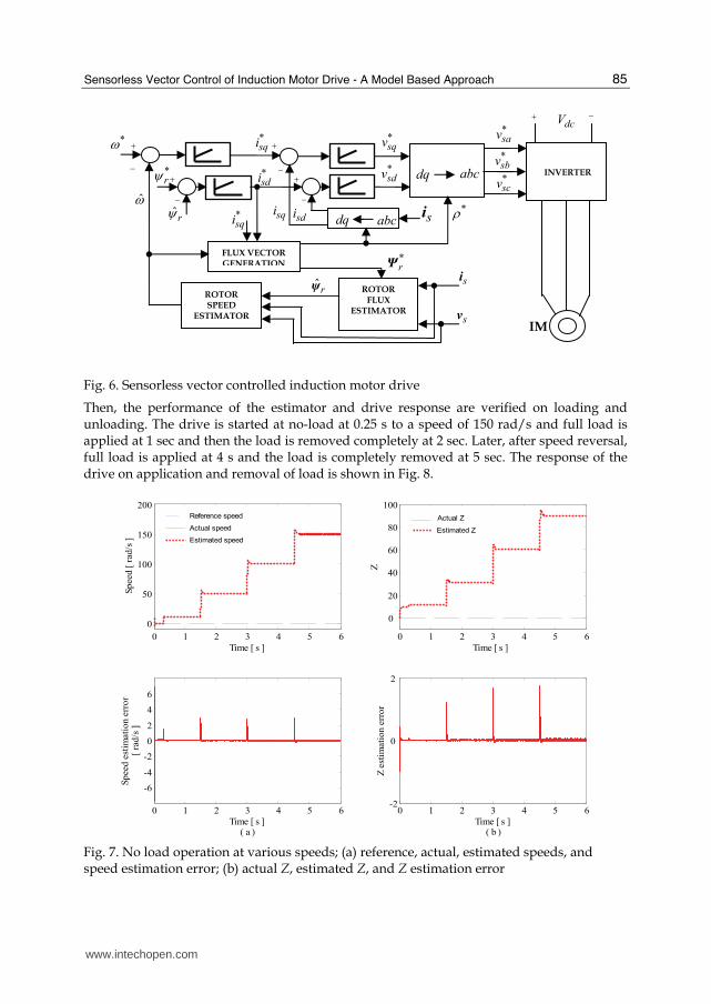
2.4.3 Simulation results
Simulation is carried out in order to verify the accuracy of the estimation algorithm and to see
the response of the sensorless drive system. The block diagram of sensorless vector controlled
induction motor drive incorporating the flux and speed estimators is shown in Fig. 6.
First, the sensorless drive is run at no load at various speeds to verify the performance of the
observer under no load condition. The drive is started at no-load and is run at various
speeds by increasing it in steps to 10 rad/s, 50 rad/s, 100 rad/s and 150 rad/s at 0.3 sec, 1.5
sec, 3 sec and 4.5 sec respectively. The speed of the motor ( )ω , estimated speed ˆ( )ω ,
reference speed *( )ω and speed estimation error ˆ( )ω ω− are shown in Fig. 7 (a). Fig. 7 (b)
shows the actual Z, estimated Z and Z estimation error ( ˆZ Z− ).
www.intechopen.com
Sensorless Vector Control of Induction Motor Drive - A Model Based Approach
85
Fig. 6. Sensorless vector controlled induction motor drive
Then, the performance of the estimator and drive response are verified on loading and unloading. The drive is started at no-load at 0.25 s to a speed of 150 rad/s and full load is applied at 1 sec and then the load is removed completely at 2 sec. Later, after speed reversal, full load is applied at 4 s and the load is completely removed at 5 sec. The response of the drive on application and removal of load is shown in Fig. 8.
0 1 2 3 4 5 6
0
50
100
150
200
Time [ s ]
Sp
eed
[ r
ad
/s ]
0 1 2 3 4 5 6
-6
-4
-2
0
2
4
6
Time [ s ] ( a )
Sp
eed
est
imati
on e
rro
r [
rad
/s ]
0 1 2 3 4 5 6
0
20
40
60
80
100
Time [ s ]
Z
0 1 2 3 4 5 6-2
0
2
Time [ s ] ( b )
Z e
stim
ati
on
err
or
Reference speed
Estimated speed
Actual speed
Actual Z
Estimated Z
Fig. 7. No load operation at various speeds; (a) reference, actual, estimated speeds, and speed estimation error; (b) actual Z, estimated Z, and Z estimation error
dcV *ω + +
+ INVERTER
−
−
−−
+
IM
*sdi
*sqi
abc
ω
dq
ROTOR
FLUX
ESTIMATOR
abcdq
ROTOR
SPEED
ESTIMATOR
si
sv
*sqv
*sdv
*sav
*sbv
*scv
*ρ*rψ
FLUX VECTOR
GENERATION
+
ˆrψ−
sdisqi*sqi
*rΨ
si
ˆrψ
www.intechopen.com
Electric Machines and Drives
86
0 1 2 3 4 5 6-200
-100
0
100
200
Time [ s ]
Sp
eed
[ r
ad
/s ]
0 1 2 3 4 5 6-8
-4
0
4
8
Time [ s ] ( a )
Sp
eed
est
imati
on
err
or
[ ra
d/s
]
0 1 2 3 4 5 6
0
20
40
60
80
100
120
Time [ s ]
Z
0 1 2 3 4 5 6-3
-2
-1
0
1
2
3
Time [ s ] ( b )
Z e
stim
ati
on
err
or
Reference speed
Estimated speed
Actual speed
Actual Z
Estimated Z
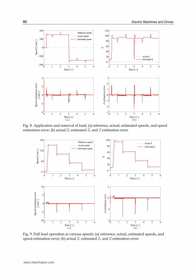
Fig. 8. Application and removal of load; (a) reference, actual, estimated speeds, and speed estimation error; (b) actual Z, estimated Z, and Z estimation error.
0 1 2 3 4 5 6
0
60
120
180
Time [ s ]
Sp
eed
[ r
ad
/s ]
0 1 2 3 4 5 6-10
-5
0
5
10
Time [ s ]( a )
Sp
eed
est
imati
on e
rro
r [
rad
/s ]
0 1 2 3 4 5 6
0
20
40
60
80
100
Time [ s ]
Z
0 1 2 3 4 5 6-4
-2
0
2
Time [ s ] ( b )
Z e
stim
ati
on e
rro
r
Reference speed
Estimated speed
Actual speedActual Z
Estimated Z
Fig. 9. Full load operation at various speeds; (a) reference, actual, estimated speeds, and speed estimation error; (b) actual Z, estimated Z, and Z estimation error.
www.intechopen.com
Sensorless Vector Control of Induction Motor Drive - A Model Based Approach
87
The estimator performance and drive response are then verified under fully loaded condition of the drive at various operating speeds. The fully loaded machine is accelerated to 150 rad/s at 0.3 s, and then the speed is reduced in steps to 100 rad/s, 50 rad/s and 10 rad/s at 1.5 sec, 3 sec and 4.5 sec respectively. Fig. 9 shows the estimation results and response of the drive during the operation. Good speed estimation accuracy was obtained under both dynamic and steady state conditions under various operating conditions and response of the VC induction motor drive incorporating the estimation algorithms was found to be good. The speed estimation algorithm presented in this section depends upon the knowledge of the rotor flux, whereas, the rotor flux estimator is independent of rotor speed and requiring only the measurable stator terminal quantities, the stator voltage and current.
3. Flux and speed estimation
Induction machines do not allow rotor flux to be easily measured. The current model and
the voltage model are the traditional solutions, and their benefits and drawbacks are well
known. Various observers for flux estimation were analyzed in the work by Verghese and
Sanders (Verghese & Sanders, 1988) and Jansen and Lorenz (Jansen & Lorenz, 1994). Over
the years several other have been presented, many of which include speed estimation
(Tajima & Hori, 1993; Kim et al., 1994; Ohtani et al., 1992; Kubota et al., 1993; Sathiakumar,
2000; Yan et al., 2000).
Tajima & Hori (Tajima & Hori, 1993) proposed MRAS (Schauder, 1992) with novel pole
allocation method for speed estimation while rotor flux estimation was done using
Gopinath’s observer. Extended Kalman Filter was used in (Kim et al., 1994) for estimating
the rotor flux and speed using a full order model of the motor assuming that rotor speed is a
constant. Ohtani et al (Ohtani et al., 1992) used the voltage model for flux estimation
overcoming the problem associated with integrator and low pass filter while speed was
obtained using a frequency controller. A speed adaptive flux observer was proposed in
(Kubota et al., 1993) for estimating rotor flux and speed. Gopinath style reduced order
observer was used in (Sathiakumar, 2000) for estimating the rotor flux while the speed was
computed using an equation derived from the motor model. Yan et al (Yan et al., 2000)
proposed a flux and speed estimator based on the sliding-mode control methodology.
In this section, we present a new flux estimation algorithm for speed sensorless rotor flux
oriented controlled induction motor drive (Thongam & Ouhrouche, 2006). The proposed
method is based on observing the variable Z introduced in Section 2 which when
introduced makes the right hand side of the conventional motor model independent of
rotor flux and speed. Rotor flux estimation is achieved using an equation obtained after
introduction of the newly defined quantity into the Blaschke equation or commonly
known as the current model; while, speed is computed using a simple equation obtained
using the new quantity Z.
3.1 Estimation of rotor flux and speed
The speed computation equation (22) obtained in section 2.4.2 requires the knowledge of
rotor flux and Z. Here, we present a joint rotor flux and speed estimation algorithm. The
block diagram of the proposed rotor flux and speed estimation algorithm is shown in
Fig. 10.
www.intechopen.com
Electric Machines and Drives
88
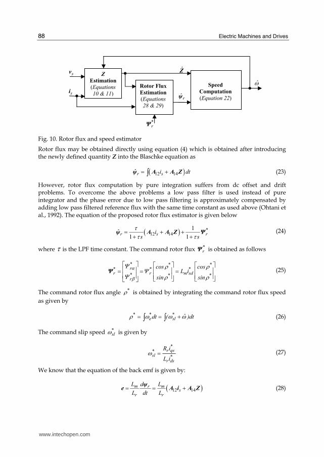
Fig. 10. Rotor flux and speed estimator
Rotor flux may be obtained directly using equation (4) which is obtained after introducing the newly defined quantity Z into the Blaschke equation as
( )12 14ˆ r si dt= +∫ψ A A Z (23)
However, rotor flux computation by pure integration suffers from dc offset and drift problems. To overcome the above problems a low pass filter is used instead of pure integrator and the phase error due to low pass filtering is approximately compensated by adding low pass filtered reference flux with the same time constant as used above (Ohtani et al., 1992). The equation of the proposed rotor flux estimator is given below
( ) *12 14
1ˆ
1 1r s ri
s s
ττ τ= + ++ +ψ A A Z Ψ (24)
where τ is the LPF time constant. The command rotor flux *rΨ is obtained as follows
* * *r* * *
r r m sd* * *r
cos cosL i
sin sin
αβ
Ψ ρ ρΨΨ ρ ρ⎡ ⎤ ⎡ ⎤ ⎡ ⎤⎢ ⎥ ⎢ ⎥ ⎢ ⎥= = =⎢ ⎥ ⎢ ⎥ ⎢ ⎥⎣ ⎦ ⎣ ⎦⎣ ⎦
Ψ (25)
The command rotor flux angle *ρ is obtained by integrating the command rotor flux speed
as given by
* * *e sl ˆdt ( )dtρ ω ω ω= = +∫ ∫ (26)
The command slip speed *slω is given by
*
*
*
r qssl
r ds
R i
L iω = (27)
We know that the equation of the back emf is given by:
( )12 14m mr
sr r
L Ld
L dt L= = +ψ
e A i A Z (28)
ω
sv
Speed
Computation
(Equation 22)
ZZ
Estimation
(Equations
10 & 11)si Rotor Flux
Estimation
(Equations
28 & 29)
rψ
*rΨ
www.intechopen.com
Sensorless Vector Control of Induction Motor Drive - A Model Based Approach
89
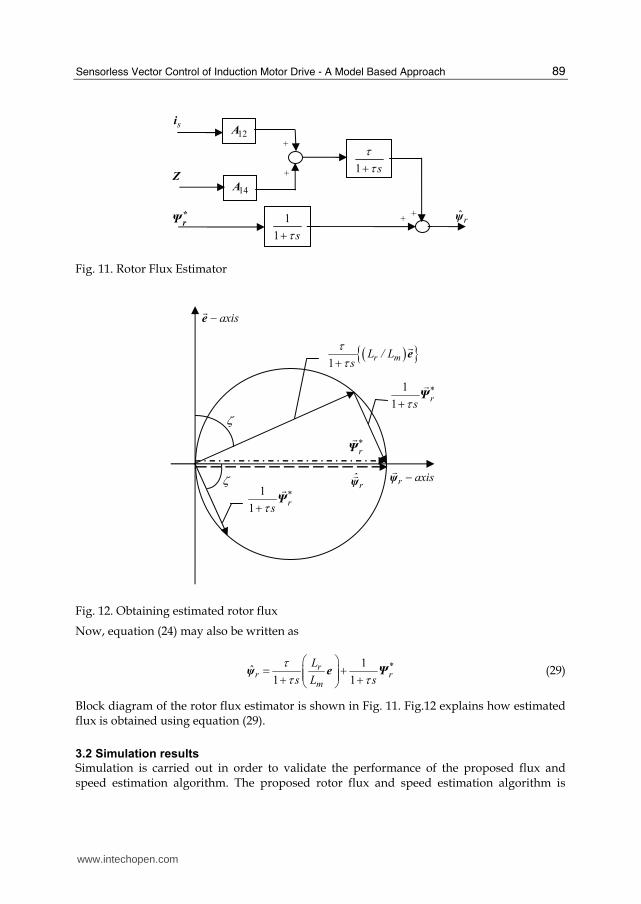
Fig. 11. Rotor Flux Estimator
Fig. 12. Obtaining estimated rotor flux
Now, equation (24) may also be written as
*1ˆ
1 1
rr r
m
L
s L s
ττ τ
⎛ ⎞= +⎜ ⎟⎜ ⎟+ +⎝ ⎠ψ e Ψ (29)
Block diagram of the rotor flux estimator is shown in Fig. 11. Fig.12 explains how estimated flux is obtained using equation (29).
3.2 Simulation results
Simulation is carried out in order to validate the performance of the proposed flux and speed estimation algorithm. The proposed rotor flux and speed estimation algorithm is
axis−ef
*rΨ
f
r axis−ψf
ζ
ζ1
1
*r
sτ+ Ψf
( ){ }1
r mL / Ls
ττ+ e
f
1
1
*r
sτ+ Ψf
rψf
si
Z
*
rΨ ˆrψ
12A
1
1 sτ++
+
1 s
ττ+
14A
+
+
www.intechopen.com
Electric Machines and Drives
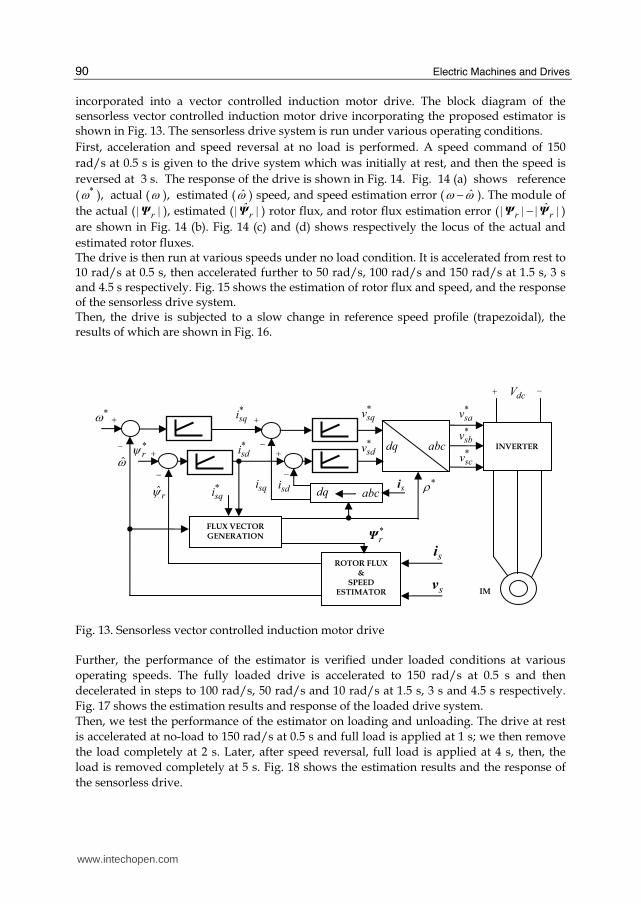
90
incorporated into a vector controlled induction motor drive. The block diagram of the sensorless vector controlled induction motor drive incorporating the proposed estimator is shown in Fig. 13. The sensorless drive system is run under various operating conditions.
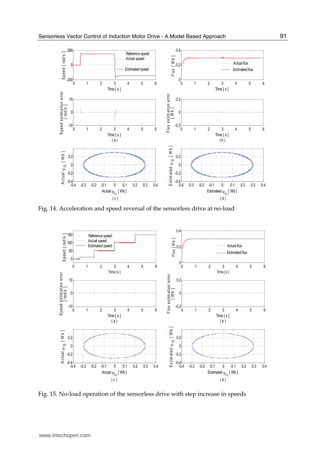
First, acceleration and speed reversal at no load is performed. A speed command of 150
rad/s at 0.5 s is given to the drive system which was initially at rest, and then the speed is
reversed at 3 s. The response of the drive is shown in Fig. 14. Fig. 14 (a) shows reference
( *ω ), actual (ω ), estimated ( ω ) speed, and speed estimation error ( ˆω ω− ). The module of
the actual ( r| |Ψ ), estimated ( rˆ| |Ψ ) rotor flux, and rotor flux estimation error ( r r
ˆ| | | |−Ψ Ψ )
are shown in Fig. 14 (b). Fig. 14 (c) and (d) shows respectively the locus of the actual and
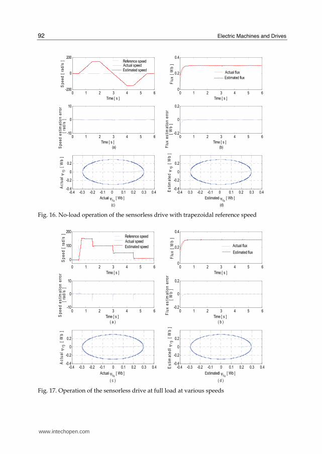
estimated rotor fluxes. The drive is then run at various speeds under no load condition. It is accelerated from rest to 10 rad/s at 0.5 s, then accelerated further to 50 rad/s, 100 rad/s and 150 rad/s at 1.5 s, 3 s and 4.5 s respectively. Fig. 15 shows the estimation of rotor flux and speed, and the response of the sensorless drive system. Then, the drive is subjected to a slow change in reference speed profile (trapezoidal), the results of which are shown in Fig. 16.
Fig. 13. Sensorless vector controlled induction motor drive Further, the performance of the estimator is verified under loaded conditions at various
operating speeds. The fully loaded drive is accelerated to 150 rad/s at 0.5 s and then
decelerated in steps to 100 rad/s, 50 rad/s and 10 rad/s at 1.5 s, 3 s and 4.5 s respectively.
Fig. 17 shows the estimation results and response of the loaded drive system.
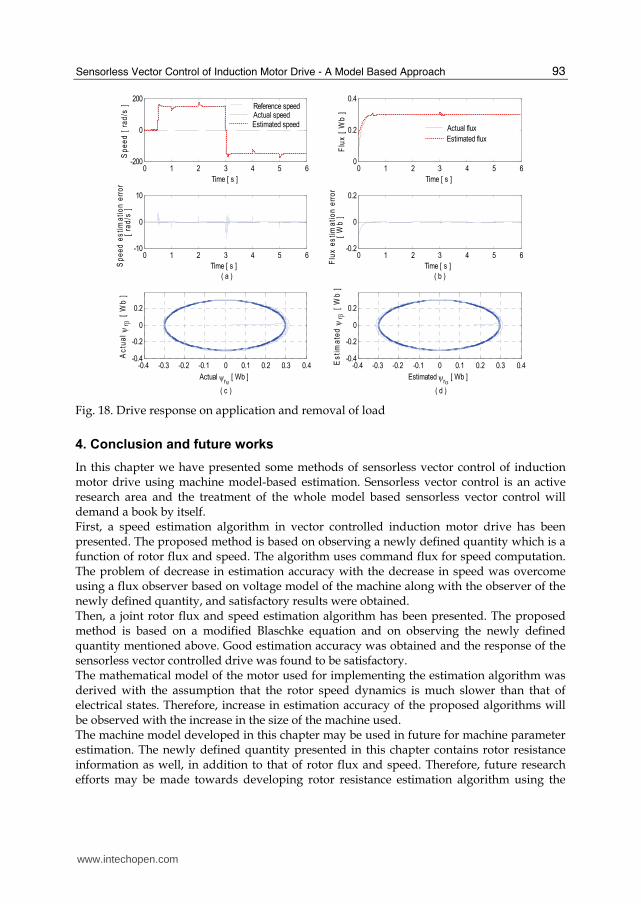
Then, we test the performance of the estimator on loading and unloading. The drive at rest
is accelerated at no-load to 150 rad/s at 0.5 s and full load is applied at 1 s; we then remove
the load completely at 2 s. Later, after speed reversal, full load is applied at 4 s, then, the
load is removed completely at 5 s. Fig. 18 shows the estimation results and the response of
the sensorless drive.
*ω
dcV
+ +
+ INVERTER
−
−
−−
+
IM
*sdi
*sqi
abc
ω dq
ROTOR FLUX
&
SPEED
ESTIMATOR
abcdq
si
sv
*sqv
*sdv
*sav
*sbv
*scv
*ρ
*rψ
FLUX VECTOR GENERATION
+
ˆrψ
−sdisqi*
sqi
*rΨ
si
www.intechopen.com
Sensorless Vector Control of Induction Motor Drive - A Model Based Approach
91
0 1 2 3 4 5 6-200
0
200
Sp
ee
d [
ra
d/s
]
Time [ s ]
0 1 2 3 4 5 6-10
0
10
Time [ s ]
( a )
Sp
ee
d e
sti
ma
tio
n e
rro
r
[ r
ad
/s ]
0 1 2 3 4 5 60
0.2
0.4
Time [ s ]
Flu
x [
Wb
]
0 1 2 3 4 5 6-0.2
0
0.2
Time [ s ]
( b )
Flu
x e
sti
ma
tio
n e
rro
r
[ W
b ]
-0.4 -0.3 -0.2 -0.1 0 0.1 0.2 0.3 0.4-0.4
-0.2
0
0.2
Actual ψrα [ Wb ]
( c )
Ac
tua
l ψ r β
[ W
b ]
-0.4 -0.3 -0.2 -0.1 0 0.1 0.2 0.3 0.4-0.4
-0.2
0
0.2
Estimated ψrα [ Wb ]
( d )
Es
tim
ate
d ψ r
β [ W
b ]
Reference speedActual speed
Estimated speed
Actual flux
Estimated flux
Fig. 14. Acceleration and speed reversal of the sensorless drive at no-load
0 1 2 3 4 5 6
0
50
100
150
Time [ s ]
Sp
ee
d [
ra
d/s
]
0 1 2 3 4 5 6-10
0
10
Time [ s ]
( a )
Sp
ee
d e
sti
ma
tio
n e
rro
r[
rad
/s ]
0 1 2 3 4 5 60
0.2
0.4
Time [ s ]
Flu
x [
Wb
]
0 1 2 3 4 5 6-0.2
0
0.2
Time [ s ]
( b )
Flu
x e
sti
ma
tio
n e
rro
r[
Wb
]
-0.4 -0.3 -0.2 -0.1 0 0.1 0.2 0.3 0.4-0.4
-0.2
0
0.2
Actual ψrα [ Wb ]
( c )
Ac
tua
l ψ r β
[ W
b ]
-0.4 -0.3 -0.2 -0.1 0 0.1 0.2 0.3 0.4-0.4
-0.2
0
0.2
Estimated ψrα [ Wb ]
( d )
Es
tim
ate
d ψ r
β [ W
b ]
Reference speedActual speedEstimated speed Actual flux
Estimated flux
Fig. 15. No-load operation of the sensorless drive with step increase in speeds
www.intechopen.com
Electric Machines and Drives
92
0 1 2 3 4 5 6-200
0
200
Time [ s ]
Sp
ee
d [
ra
d/s
]
0 1 2 3 4 5 60
0.2
0.4
Time [ s ]
Flu
x [
Wb
]
0 1 2 3 4 5 6-10
0
10
Time [ s ]
(a) Sp
ee
d e
sti
ma
tio
n e
rro
r
[
ra
d/s
]
0 1 2 3 4 5 6-0.2
0
0.2
Time [ s ]
(b) Flu
x e
sti
ma
tio
n e
rro
r
[
Wb
]
-0.4 -0.3 -0.2 -0.1 0 0.1 0.2 0.3 0.4 -0.4
-0.2
0
0.2
Actual ψrα [ Wb ]
(c)
Ac
tua
l ψ r β
[ W
b ]
-0.4 0.3 -0.2 -0.1 0 0.1 0.2 0.3 0.4 -0.4
-0.2
0
0.2
Estimated ψrα [ Wb ]
(d)
Es
tim
ate
d ψ r
β [ W
b ]
Reference speedActual speedEstimated speed
Actual flux
Estimated flux
Fig. 16. No-load operation of the sensorless drive with trapezoidal reference speed
0 1 2 3 4 5 6
0
100
200
Time [ s ]
Sp
ee
d [
ra
d/s
]
0 1 2 3 4 5 6-10
0
10
Time [ s ]
( a )
Sp
ee
d e
sti
ma
tio
n e
rro
r [
rad
/s ]
0 1 2 3 4 5 60
0.2
0.4
Time [ s ]
Flu
x [
Wb
]
0 1 2 3 4 5 6-0.2
0
0.2
Time [ s ]
( b )
Flu
x e
sti
ma
tio
n e
rro
r [
Wb
]
-0.4 -0.3 -0.2 -0.1 0 0.1 0.2 0.3 0.4-0.4
-0.2
0
0.2
Actual ψrα [ Wb ]
( c )
Ac
tua
l ψ r β
[ W
b ]
-0.4 -0.3 -0.2 -0.1 0 0.1 0.2 0.3 0.4-0.4
-0.2
0
0.2
Estimatedl ψrα [ Wb ]
( d )
Es
tim
ate
dl ψ r β
[ W
b ]
Reference speed
Estimated speed
Actual speedActual flux
Estimated flux
Fig. 17. Operation of the sensorless drive at full load at various speeds
www.intechopen.com
Sensorless Vector Control of Induction Motor Drive - A Model Based Approach
93
0 1 2 3 4 5 6-200
0
200
Time [ s ]
Sp
ee
d [
ra
d/s
]
0 1 2 3 4 5 60
0.2
0.4
Time [ s ]
Flu
x [
Wb
]
0 1 2 3 4 5 6-10
0
10
Time [ s ]
( a )
Sp
ee
d e
sti
ma
tio
n e
rro
r
[
ra
d/s
]
0 1 2 3 4 5 6-0.2
0
0.2
Time [ s ]
( b )
Flu
x e
sti
ma
tio
n e
rro
r
[ W
b ]
-0.4 -0.3 -0.2 -0.1 0 0.1 0.2 0.3 0.4-0.4
-0.2
0
0.2
Actual ψrα [ Wb ]
( c )
Ac
tua
l ψ r β
[ W
b ]
-0.4 -0.3 -0.2 -0.1 0 0.1 0.2 0.3 0.4-0.4
-0.2
0
0.2
Estimated ψrα [ Wb ]
( d )
Es
tim
ate
d ψ r
β [ W
b ]
Reference speedActual speedEstimated speed Actual flux
Estimated flux
Fig. 18. Drive response on application and removal of load
4. Conclusion and future works
In this chapter we have presented some methods of sensorless vector control of induction motor drive using machine model-based estimation. Sensorless vector control is an active research area and the treatment of the whole model based sensorless vector control will demand a book by itself. First, a speed estimation algorithm in vector controlled induction motor drive has been presented. The proposed method is based on observing a newly defined quantity which is a function of rotor flux and speed. The algorithm uses command flux for speed computation. The problem of decrease in estimation accuracy with the decrease in speed was overcome using a flux observer based on voltage model of the machine along with the observer of the newly defined quantity, and satisfactory results were obtained. Then, a joint rotor flux and speed estimation algorithm has been presented. The proposed method is based on a modified Blaschke equation and on observing the newly defined quantity mentioned above. Good estimation accuracy was obtained and the response of the sensorless vector controlled drive was found to be satisfactory. The mathematical model of the motor used for implementing the estimation algorithm was derived with the assumption that the rotor speed dynamics is much slower than that of electrical states. Therefore, increase in estimation accuracy of the proposed algorithms will be observed with the increase in the size of the machine used. The machine model developed in this chapter may be used in future for machine parameter estimation. The newly defined quantity presented in this chapter contains rotor resistance information as well, in addition to that of rotor flux and speed. Therefore, future research efforts may be made towards developing rotor resistance estimation algorithm using the
www.intechopen.com
Electric Machines and Drives
94
new machine model. Further, in the proposed algorithms rotor flux was necessary for speed estimation. Future research efforts may also be made towards developing a speed estimation algorithm for which the knowledge of rotor flux is not necessary.
5. References
Abbondante, A. & Brennen, M. B. (1975). Variable speed induction motor drives use electronic slip calculator based on motor voltages and currents. IEEE Trans. Ind. Appl, Vol. 1A-11, No. 5, Sept/Oct, pp. 483-488.
Ben-Brahim, L. & Kudor, T. (1995). Implementation of an induction motor speed estimator using neural networks. Proceedings of International Power Electronics Conference, IPEC 1995, Yokohama, April, pp. 52-58.
Bodson, M.; Chiasson, J. & Novotnak, R. T. (1995). Nonlinear Speed Observer for High Performance Induction Motor Control. IEEE Trans. Ind. Elec, Vol. 42, No. 4, Aug. pp. 337-343.
Choy, I.; Kwon, S. H.; Lim J. & Hong, S. W. (1996). Robust Speed Estimation for Tacholess Induction Motor Drives. IEEE Electronics Letters, Vol. 32, No. 19, pp. 1836-1838.
Comnac V.; Cernat M.; Cotorogea, M. & Draghici, I. (2001). Sensorless Direct Torque and Stator Flux Control of Induction Machines Using an Extended Kalman Filter", Proceedings of IEEE Int. Conf. on Control Appl, Mexico, Sept. 5-7, pp. 674-679.
Du T.; Vas, P. & Stronach, F. (1995). Design and Application of Extended Observers for Joint State and Parameter Estimation in High Performance AC Drives. IEE Proc. Elec. Power Appl., Vol. 142, No. 2, pp. 71-78.
Fodor, D. ; Ionescu, F. ; Floricau, D. ; Six, J.P. ; Delarue, P. ; Diana, D. & Griva, G. (1995). Neural Networks Applied for Induction Motor Speed Sensorless Estimation. Proceedings of the IEEE International Symposium on Industrial Electronics, ISIE’ 95, July 10-14, Athens, pp. 181-186.
Gopinath, B. (1971). On the Control of Linear Multiple Input-Output Systems. Bell System Technical Journal, Vol. 50, No. 3, March, pp. 1063-1081.
Haghgoeian, F.; Ouhrouche, M. & Thongam, J. S. (2005). MRAS-based speed estimation for an induction motor sensorless drive using neural networks. WSEAS Transactions on Systems, Vol. 4, No. 12, December, pp. 2346-2352.
Jansen, P. L. & Lorenz, R. D. (1994). A physically insightful approach to the design and accuracy assessment of flux observers for field oriented induction machine drives. IEEE Trans. Ind. App., Vol. 30, No. l, Jan. /Feb., pp. 101-110.
Kim, S. H.; Park, T. S.; Yoo, J. Y. & Park, G. T. (2001). Speed-sensorless vector control of an induction motor using neural network speed estimation. IEEE Trans. Ind. Elec, Vol. 48, No. 3, June, pp. 609-614.
Kim, Y. R.; Sul S. K. & and Park, M. H. (1994). Speed sensorless vector control of induction motor using extended Kalman filter. IEEE Trans. Ind. Appl., Vol. 30, No. 5, Sept/Oct, pp. 1225-1233.
Kubota, H.; Matsuse K. & Nakano, T. (1993). DSP-based speed adaptative flux observer of induction motor. IEEE Trans. Ind. Appl, Vol. 29, No. 2, March/April, pp. 344-348.
Liu, J. J.; Kung, I. C. & Chao, H. C. (2001). Speed estimation of induction motor using a non-linear identification technique. Proc. Natl. Sci. Counc. ROC (A), Vol. 25, No. 2, pp. 107-114.
www.intechopen.com
Sensorless Vector Control of Induction Motor Drive - A Model Based Approach
95
Ma, X. & Gui, Y. (2002). Extended Kalman filter for speed sensor-less DTC based on DSP. Proc. of the 4th World Cong. on Intelligent Control and Automation, Shanghai, China, June 10-14, pp. 119-122.
Minami, K.; Veley-Reyez, M.; Elten, D.; Verghese, G. C. & Filbert, D. (1991). Multi-stage speed and parameter estimation for induction machines. Proceedings of the IEEE Power Electronics Specialists Conf., Boston, USA, pp. 596-604.
Ohtani, T.; Takada, N. & and Tanaka, K. (1992). Vector control of induction motor without shaft encoder. IEEE Trans. Ind. Appl, Vol. 28, No. 1, Jan/Feb, pp. 157-164.
Pappano, V.; Lyshevski, S. E. & Friedland, B. (1998). Identification of induction motor parameters. Proceedings of the 37th IEEE Conf. on Decision and Control, Tampa, Florida, USA, December 16-18, pp. 989-994.
Peng, F. Z. & Fukao, T. (1994). Robust speed identification for speed sensorless vector control of induction motors. IEEE Trans. Ind. Appl, Vol. 30, No. 5, Sept/Oct., pp. 1234-1240.
Rowan, T. M. & Kerkman, R. J. (1986). A new synchronous current regulator and an analysis of current-regulated PWM inverters. IEEE Trans. Ind. Appl, Vol. IA-22, No. 4, July/Aug., pp. 678-690.
Schauder, C. (1992). Adaptive speed identification for vector control of induction motors without rotational transducers. IEEE Trans. Ind. Appl, Vol. 28, No. 5, Sept./Oct., pp. 1054-1061.
Sathiakumar, S. (2000). Dynamic flux observer for induction motor speed control. Proceedings of Australian Universities Power Engineering Conf. AUPEC 2000, Brisbane, Australia, 24-27 Sept., pp. 108-113.
Simoes, M. G. & Bose, B. K. (1995). Neural network based estimation of feedback signals for a vector controlled induction motor drive. IEEE Trans. Ind. Appl., Vol. 31, May/June, pp. 620-629.
Tajima, H. & Hori, Y. (1993). Speed sensorless field-orientation control of the induction machine. IEEE Trans. Ind. Appl., Vol. 29, No. 1, pp. 175-180.
Thongam, J. S. & Thoudam, V. P. S. (2004). Stator flux based speed estimation of induction motor drive using EKF. IETE Journal of Research, India, Vol. 50, No. 3. May-June, pp 191-197.
Thongam, J. S. & Ouhrouche, M. (2006). Flux estimation for speed sensorless rotor flux oriented controlled induction motor drive. WSEAS Transactions on Systems, Vol. 5, No. 1, Jan., pp. 63-69.
Thongam, J. S. & Ouhrouche, M. (2007). A novel speed estimation algorithm in indirect vector controlled induction motor drive. International Journal of Power and Energy Systems, Vol. 27, No. 3, 2007, pp. 294-298.
Toqeer, R. S. & Bayindir, N. S. (2003). Speed estimation of an induction motor using Elman neural network. Neuro Computing, Volume 55, Issues 3-4, October, pp. 727- 730.
Velez-Reyes, M.; Minami, K. & Verghese, G. C. (1989). Recursive speed and parameter estimation for induction machines", IEEE/IAS Ann. Meet. Conf. Rec., San Diego, pp. 607-611.
Veleyez-Reyes, M. & Verghese, G. C. (1992). Decomposed algorithms for speed and parameter estimation in induction machines. IFAC Symposium on Nonlinear Control System Design, Bordeaux, France, pp. 77-82.
www.intechopen.com

Electric Machines and Drives
96
Verghese, G. C. & Sanders, S. R. (1988). Observers for flux estimation in induction machines. IEEE Trans. Ind. Elec, Vol. 35, No. 1, Feb., pp. 85-94.
Yan, Z.; Jin C. & Utkin, V. I. (2000). Sensorless sliding-mode control of induction motors. IEEE Trans. Ind. Elec, Vol. 47, No. 6, Dec., pp. 1286-1297.
www.intechopen.com

Electric Machines and DrivesEdited by Dr. Miroslav Chomat
ISBN 978-953-307-548-8Hard cover, 262 pagesPublisher InTechPublished online 28, February, 2011Published in print edition February, 2011
InTech EuropeUniversity Campus STeP Ri Slavka Krautzeka 83/A 51000 Rijeka, Croatia Phone: +385 (51) 770 447 Fax: +385 (51) 686 166www.intechopen.com
InTech ChinaUnit 405, Office Block, Hotel Equatorial Shanghai No.65, Yan An Road (West), Shanghai, 200040, China
Phone: +86-21-62489820 Fax: +86-21-62489821
The subject of this book is an important and diverse field of electric machines and drives. The twelve chaptersof the book written by renowned authors, both academics and practitioners, cover a large part of the field ofelectric machines and drives. Various types of electric machines, including three-phase and single-phaseinduction machines or doubly fed machines, are addressed. Most of the chapters focus on modern controlmethods of induction-machine drives, such as vector and direct torque control. Among others, the bookaddresses sensorless control techniques, modulation strategies, parameter identification, artificial intelligence,operation under harsh or failure conditions, and modelling of electric or magnetic quantities in electricmachines. Several chapters give an insight into the problem of minimizing losses in electric machines andincreasing the overall energy efficiency of electric drives.
How to referenceIn order to correctly reference this scholarly work, feel free to copy and paste the following:
Jogendra Singh Thongam and Rachid Beguenane (2011). Sensorless Vector Control of Induction Motor Drive- A Model Based Approach, Electric Machines and Drives, Dr. Miroslav Chomat (Ed.), ISBN: 978-953-307-548-8, InTech, Available from: http://www.intechopen.com/books/electric-machines-and-drives/sensorless-vector-control-of-induction-motor-drive-a-model-based-approach
Related Documents