SUPROCK TECHNOLOGIES Turbine Generator Torsional Vibration Monitoring using the TDMS System – Recent Applications Chris Suprock, PhD - Suprock Technologies Kevin Myers, P.E. - MPR Associates

Welcome message from author
This document is posted to help you gain knowledge. Please leave a comment to let me know what you think about it! Share it to your friends and learn new things together.
Transcript
SUPROCK TECHNOLOGIES
Turbine Generator Torsional Vibration Monitoring using the TDMS System – Recent Applications
Chris Suprock, PhD - Suprock TechnologiesKevin Myers, P.E. - MPR Associates
2 / 2 9
OutlineIntroductionBackground tutorial / refresher
Torsional vibration issue summaryDesign/acceptance criteriaImportance of, and methods for, mode identificationMethods of testing
TDMS SystemDescriptionRecent nuclear installation experienceExample data analysisPotential future applications / advancements
3 / 2 9
Introduction
Suprock Technologies• Developed Turbine Dynamics Monitoring System (TDMS) under EPRI
Program 65 funded initiative• Specialization in advanced sensor technology and machine
monitoring
MPR Associates• Has supported the power generation industry since 1964• Modeled, tested and/or analyzed >100 rotor trains with respect to
torsional vibration issues
Teaming approach to execute torsional vibration tests and related analysis for power generation industry
4 / 2 9
Torsional Vibration Background – Issue Summary
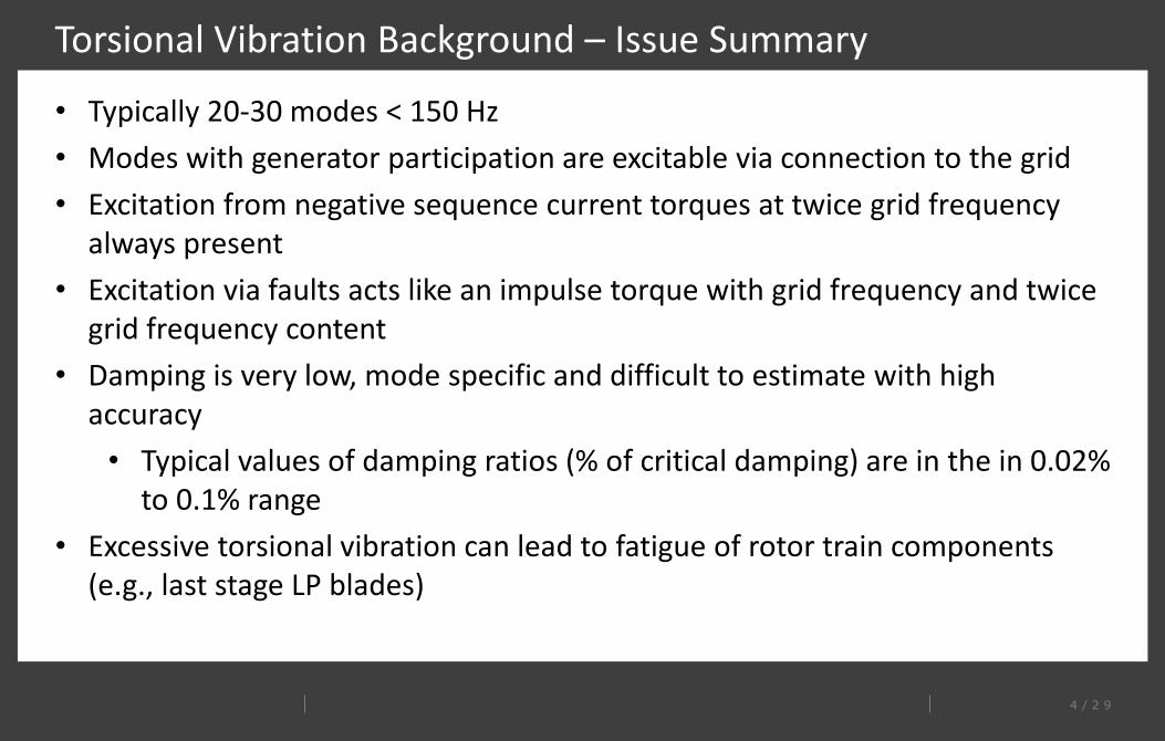
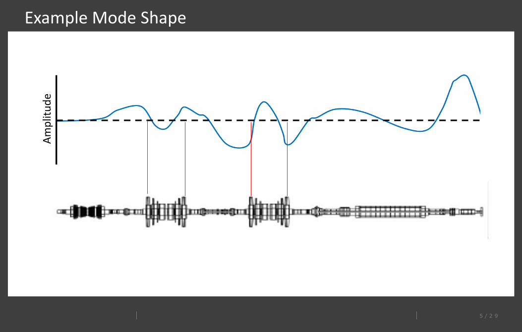
• Typically 20-30 modes < 150 Hz• Modes with generator participation are excitable via connection to the grid• Excitation from negative sequence current torques at twice grid frequency
always present• Excitation via faults acts like an impulse torque with grid frequency and twice
grid frequency content• Damping is very low, mode specific and difficult to estimate with high
accuracy• Typical values of damping ratios (% of critical damping) are in the in 0.02%
to 0.1% range• Excessive torsional vibration can lead to fatigue of rotor train components
(e.g., last stage LP blades)
5 / 2 9
Example Mode ShapeAm
plitu
de
6 / 2 9
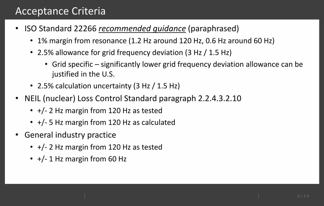
Acceptance Criteria• ISO Standard 22266 recommended guidance (paraphrased)
• 1% margin from resonance (1.2 Hz around 120 Hz, 0.6 Hz around 60 Hz)• 2.5% allowance for grid frequency deviation (3 Hz / 1.5 Hz)
• Grid specific – significantly lower grid frequency deviation allowance can be justified in the U.S.
• 2.5% calculation uncertainty (3 Hz / 1.5 Hz)• NEIL (nuclear) Loss Control Standard paragraph 2.2.4.3.2.10
• +/- 2 Hz margin from 120 Hz as tested• +/- 5 Hz margin from 120 Hz as calculated
• General industry practice• +/- 2 Hz margin from 120 Hz as tested• +/- 1 Hz margin from 60 Hz
7 / 2 9
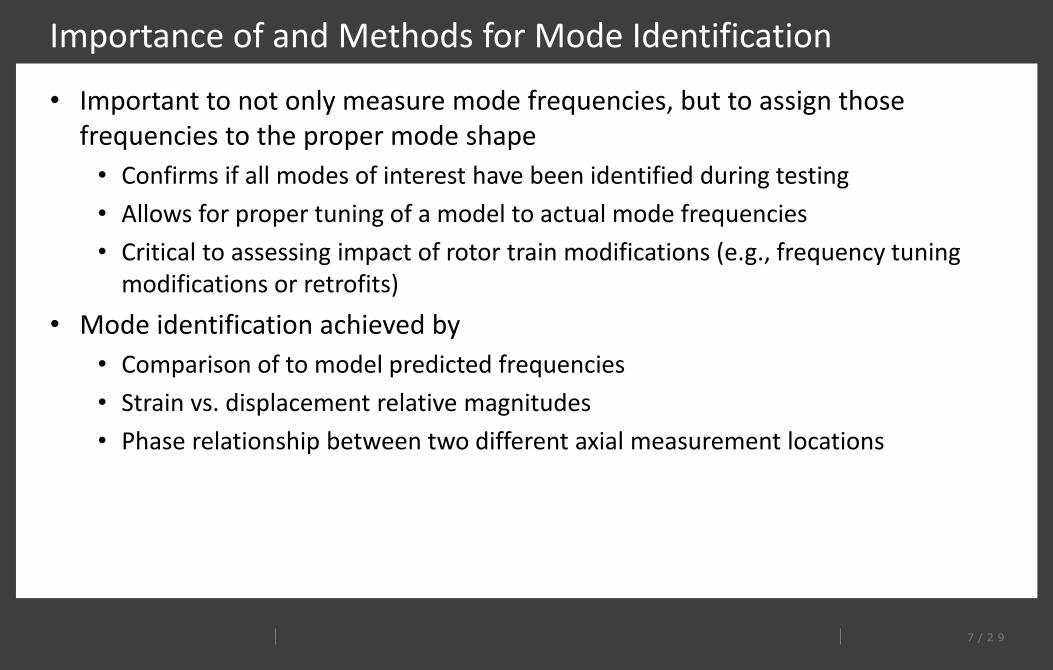
Importance of and Methods for Mode Identification
• Important to not only measure mode frequencies, but to assign those frequencies to the proper mode shape
• Confirms if all modes of interest have been identified during testing• Allows for proper tuning of a model to actual mode frequencies• Critical to assessing impact of rotor train modifications (e.g., frequency tuning
modifications or retrofits)• Mode identification achieved by
• Comparison of to model predicted frequencies• Strain vs. displacement relative magnitudes• Phase relationship between two different axial measurement locations
8 / 2 9
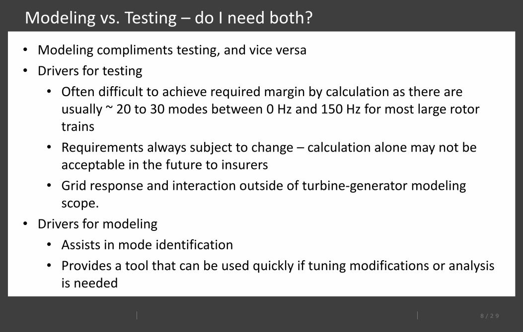
Modeling vs. Testing – do I need both?
• Modeling compliments testing, and vice versa• Drivers for testing
• Often difficult to achieve required margin by calculation as there are usually ~ 20 to 30 modes between 0 Hz and 150 Hz for most large rotor trains
• Requirements always subject to change – calculation alone may not be acceptable in the future to insurers
• Grid response and interaction outside of turbine-generator modeling scope.
• Drivers for modeling• Assists in mode identification• Provides a tool that can be used quickly if tuning modifications or analysis
is needed
9 / 2 9
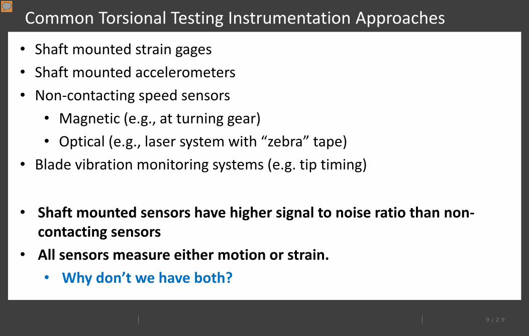
Common Torsional Testing Instrumentation Approaches Testing• Shaft mounted strain gages
• Shaft mounted accelerometers• Non-contacting speed sensors
• Magnetic (e.g., at turning gear)• Optical (e.g., laser system with “zebra” tape)
• Blade vibration monitoring systems (e.g. tip timing)
• Shaft mounted sensors have higher signal to noise ratio than non-contacting sensors
• All sensors measure either motion or strain. • Why don’t we have both?
Presenter
Presentation Notes
Discuss strain gage as still being “gold standard” to due to high sensitivity and ability to cancel out bending modes
1 0 / 2 9
EPRI developed TDMS
• TDMS- Turbine Dynamics Monitoring System• Patent and commercial license through EPRI.
• EPRI response to industry need for torsional testing.• Simple engineering documentation.• Rapid response time to test requests (days, not months or years).• Multi-dynamics telemetry increases test confidence.• Capable of long term operation during extended startups and/or monitoring.
1 1 / 2 9
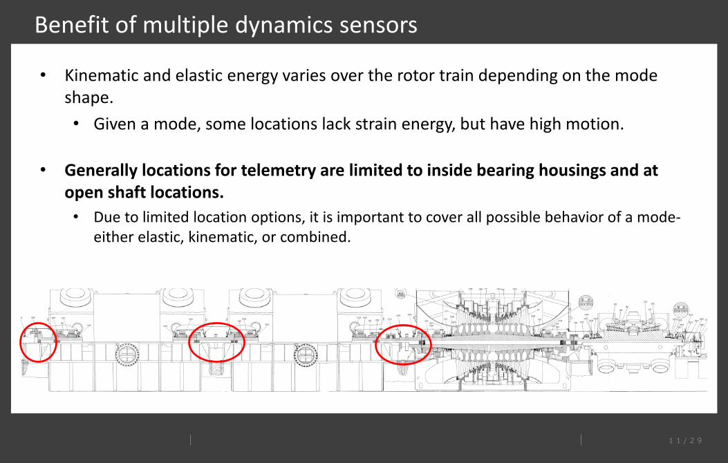
Benefit of multiple dynamics sensors
• Kinematic and elastic energy varies over the rotor train depending on the mode shape.• Given a mode, some locations lack strain energy, but have high motion.
• Generally locations for telemetry are limited to inside bearing housings and at open shaft locations.• Due to limited location options, it is important to cover all possible behavior of a mode-
either elastic, kinematic, or combined.
1 2 / 2 9
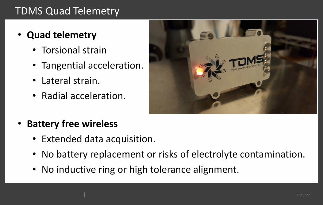
TDMS Quad Telemetry
• Quad telemetry• Torsional strain• Tangential acceleration.• Lateral strain.• Radial acceleration.
• Battery free wireless• Extended data acquisition.• No battery replacement or risks of electrolyte contamination.• No inductive ring or high tolerance alignment.
1 3 / 2 9
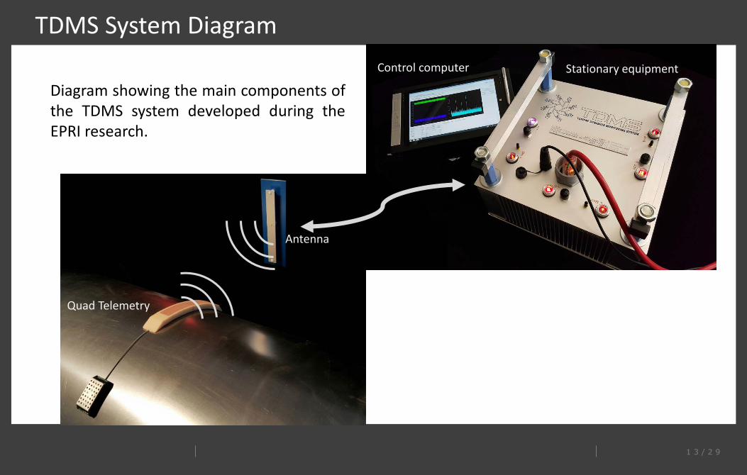
TDMS System Diagram
Radio signal
Coaxial cable
Antenna
Control computer Stationary equipment
Quad Telemetry
Diagram showing the main components ofthe TDMS system developed during theEPRI research.
1 4 / 2 9
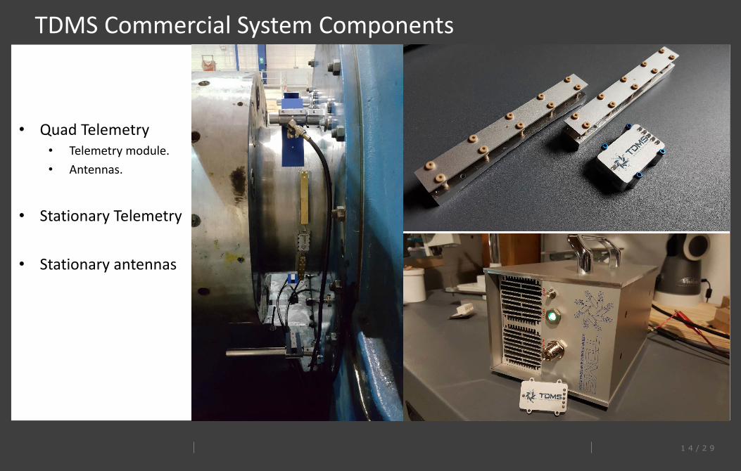
TDMS Commercial System Components
• Quad Telemetry• Telemetry module.• Antennas.
• Stationary Telemetry
• Stationary antennas
1 5 / 2 9
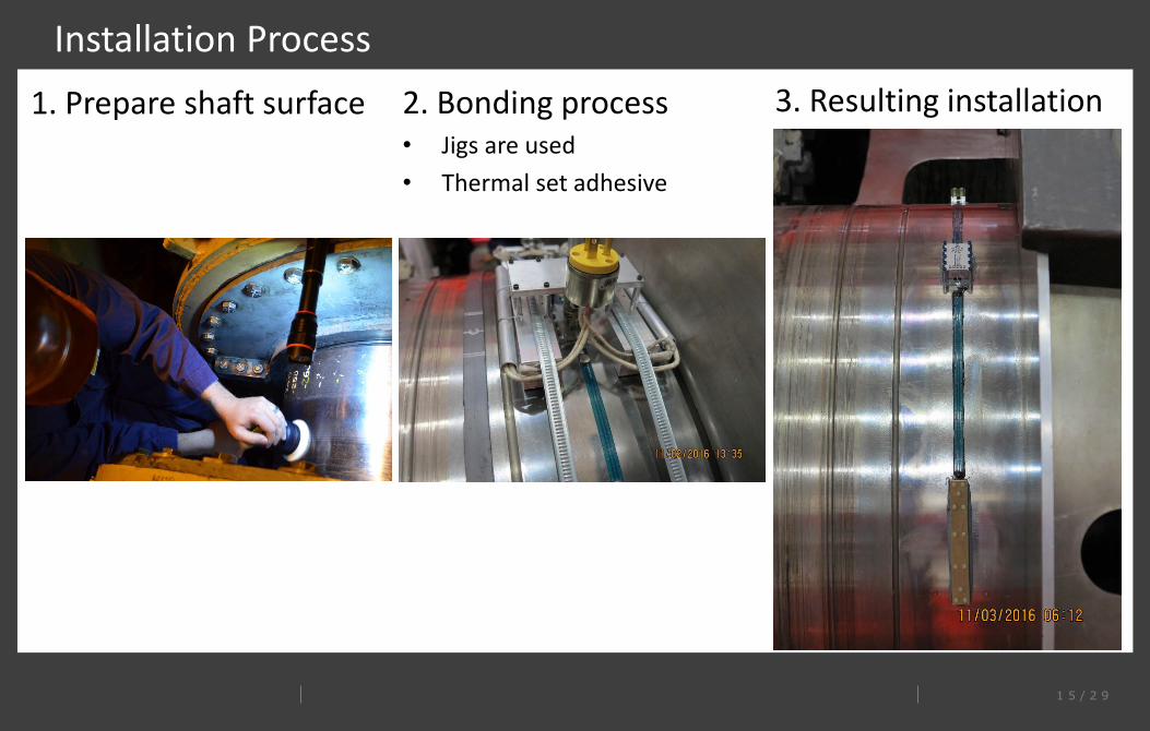
Installation Process1. Prepare shaft surface 2. Bonding process
• Jigs are used • Thermal set adhesive
3. Resulting installation
1 6 / 2 9
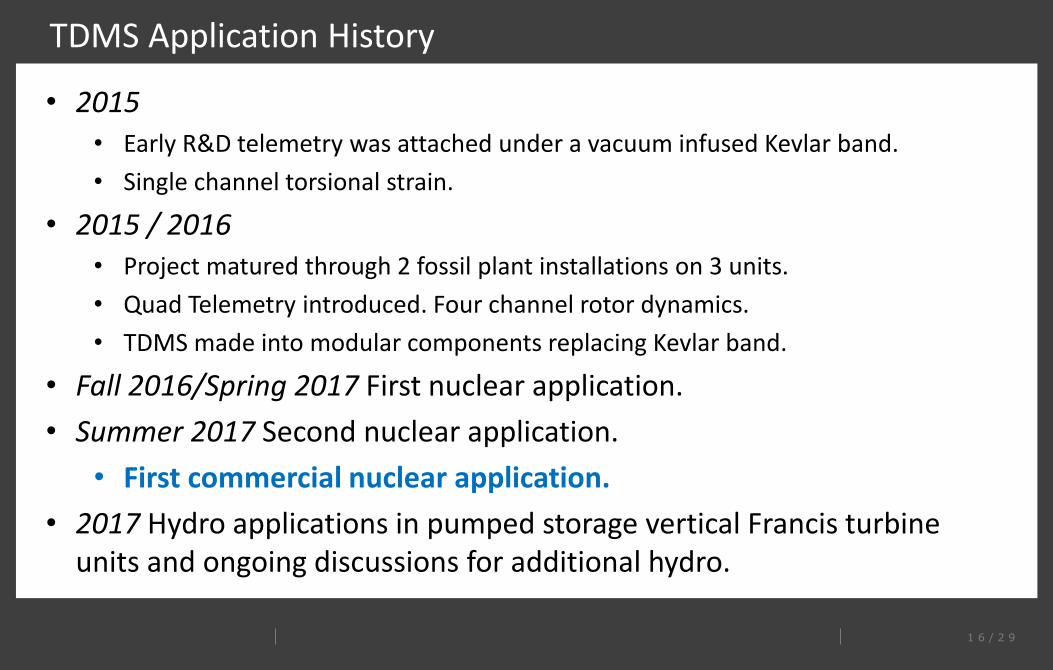
TDMS Application History
• 2015• Early R&D telemetry was attached under a vacuum infused Kevlar band.• Single channel torsional strain.
• 2015 / 2016 • Project matured through 2 fossil plant installations on 3 units.• Quad Telemetry introduced. Four channel rotor dynamics. • TDMS made into modular components replacing Kevlar band.
• Fall 2016/Spring 2017 First nuclear application.• Summer 2017 Second nuclear application.
• First commercial nuclear application.• 2017 Hydro applications in pumped storage vertical Francis turbine
units and ongoing discussions for additional hydro.
1 7 / 2 9
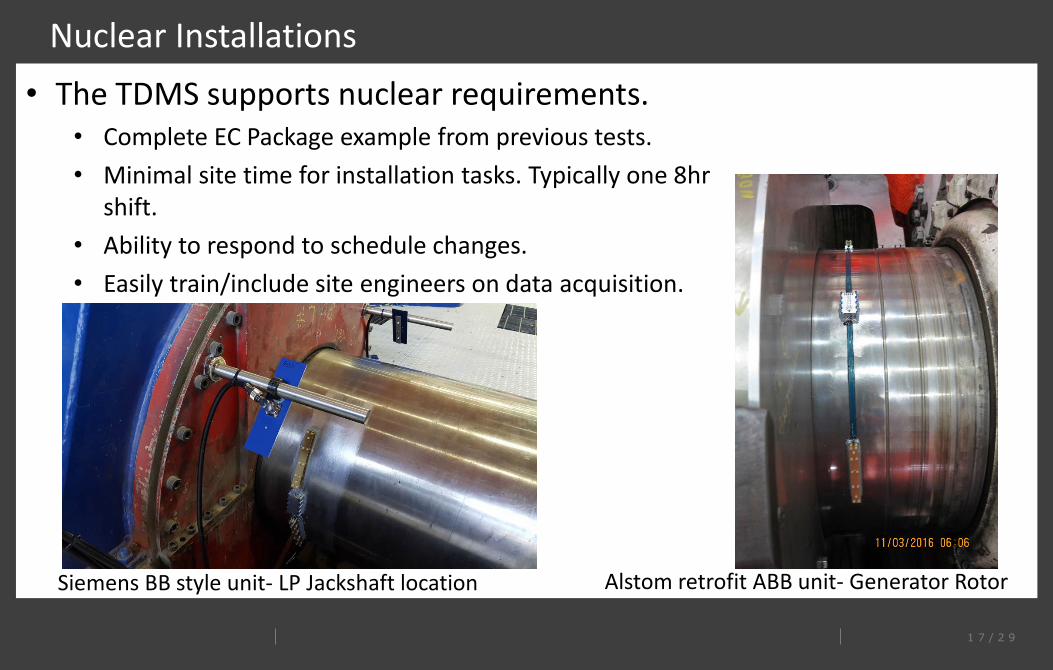
Nuclear Installations• The TDMS supports nuclear requirements.
• Complete EC Package example from previous tests.• Minimal site time for installation tasks. Typically one 8hr
shift. • Ability to respond to schedule changes.• Easily train/include site engineers on data acquisition.
Siemens BB style unit- LP Jackshaft location Alstom retrofit ABB unit- Generator Rotor
1 8 / 2 9
Data Analysis / Post-Processing
• EPRI sponsored software for the TDMS. • Suprock provides software to TDMS utilities at no cost.• Empowers utilities to continue to use equipment on-demand.• Allows engineers to post process data for reports, communication, and
documentation.
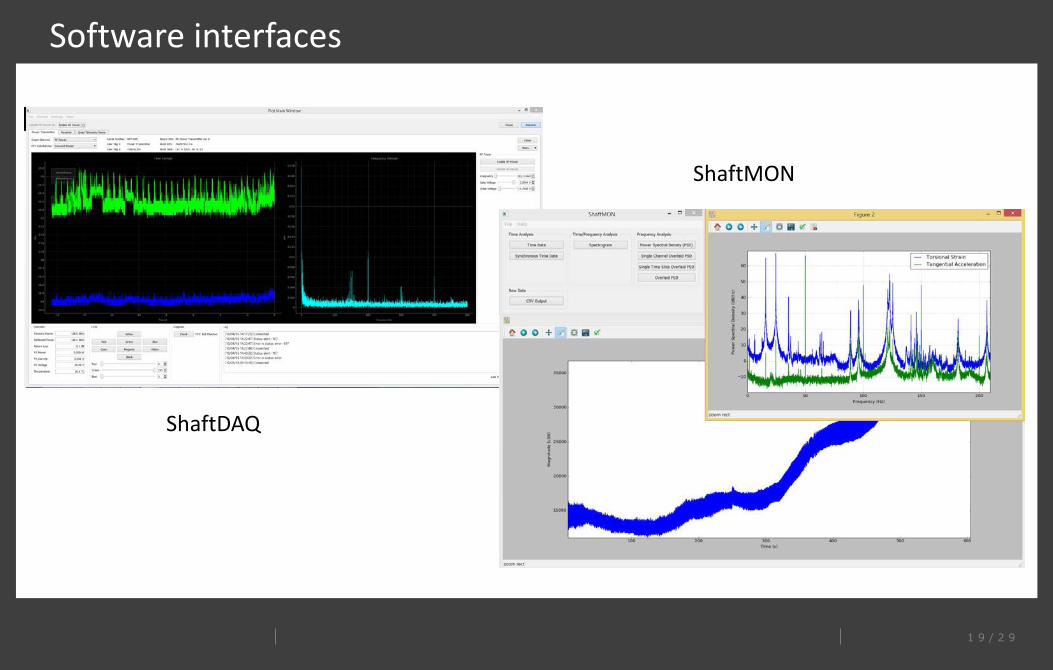
• ShaftDAQ – Data acquisition for the TDMS system• User friendly control over the DAQ process.• Utility engineers can use
• ShaftMON – Data plotting and time/frequency analysis.• PSD plots of frequency• Overlays of different sensors/time windows• Spectrograms (frequency/magnitude vs. time)• Combination of plots
1 9 / 2 9
Software interfaces
ShaftMON
ShaftDAQ
2 0 / 2 9
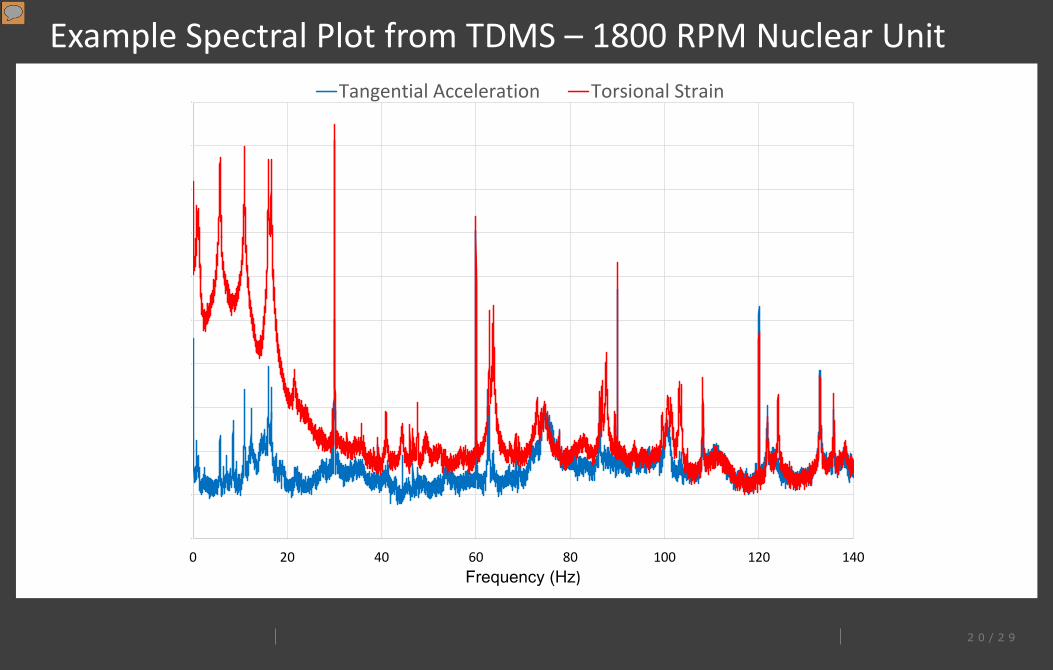
Example Spectral Plot from TDMS – 1800 RPM Nuclear Unit
-20
-10
0
10
20
30
40
50
60
70
80
0 20 40 60 80 100 120 140Frequency (Hz)
Tangential Acceleration Torsional Strain
Presenter
Presentation Notes
Highlight sensitivity of system, benefits of both strain and acceleration data for confirmation of torsional mode, and mode identification
2 1 / 2 9
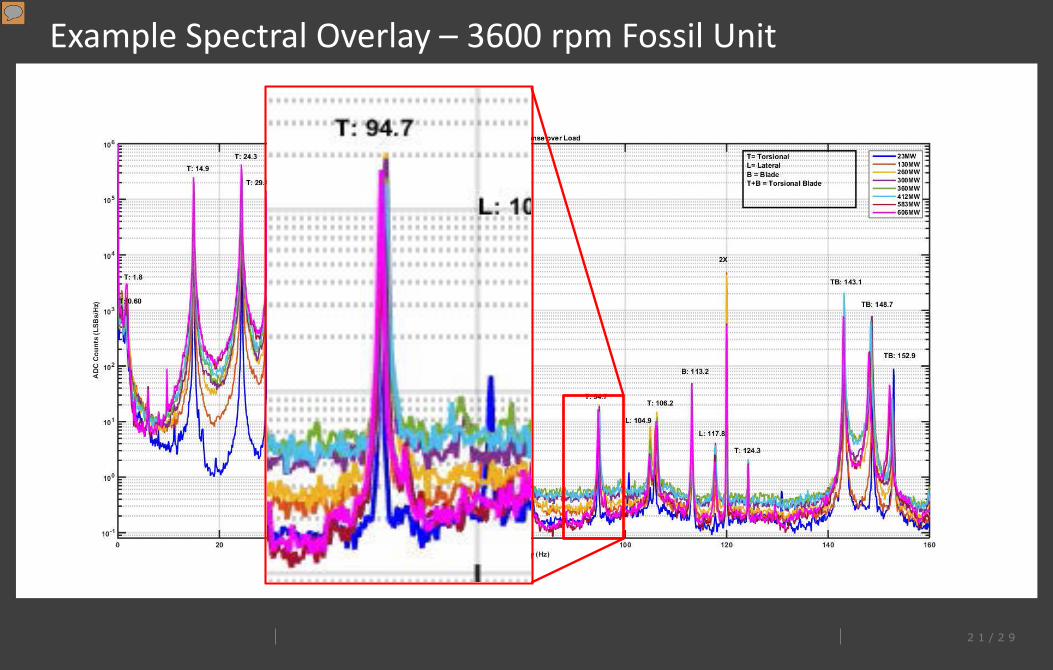
Example Spectral Overlay – 3600 rpm Fossil Unit
Presenter
Presentation Notes
Will discuss what is going on in this plot, and benefits of this information to mode identification
2 2 / 2 9
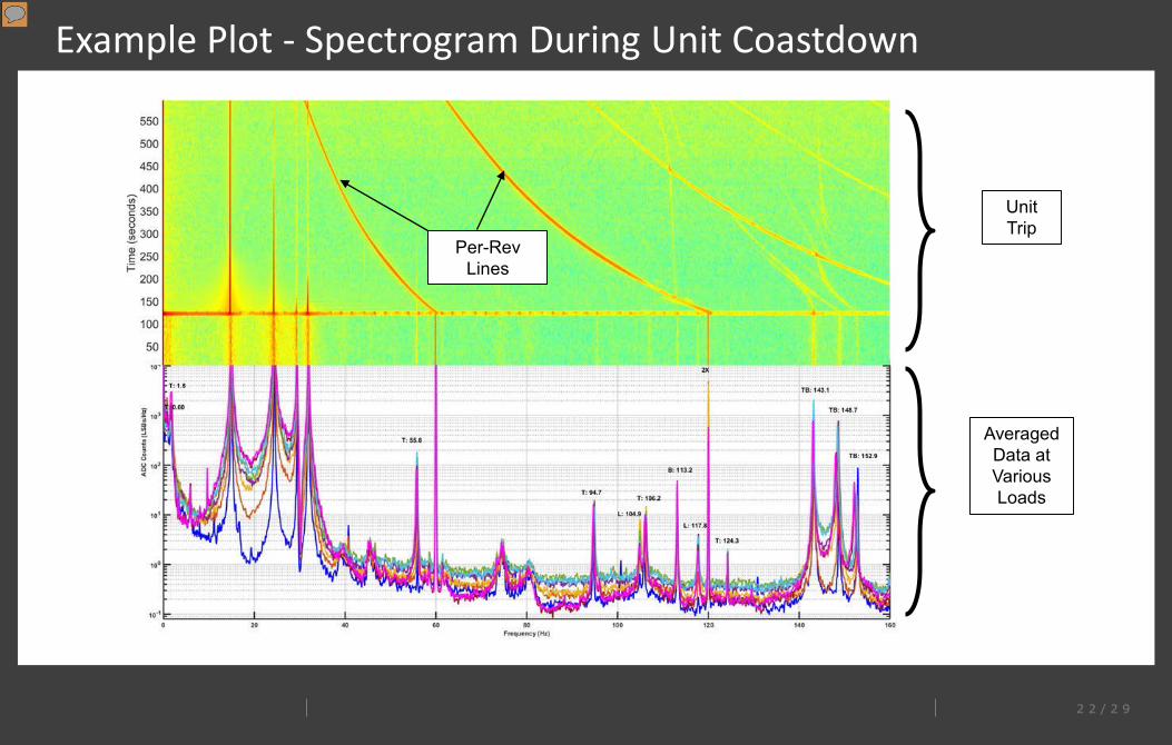
Example Plot - Spectrogram During Unit Coastdown
Per-Rev Lines
Unit Trip
Averaged Data at Various Loads
Presenter
Presentation Notes
Will discuss what is going on in this plot, and benefits of this information to mode identification
2 3 / 2 9
Reporting
• Initial evaluation can be performed near real-time• Remote monitoring has been demonstrated over network connection.• Triggered automatic monitoring is being implemented.
• Formal report typically follows within 3 weeks (can be expedited if needed)• Typically includes a table of mode frequencies as measured.• Comparison to model predicted frequencies is done if a model exists for
the rotor train.
2 4 / 2 9
Considerations for Pursuing Torsional Testing
• Is a torsional analysis available already (including level of confidence in the analysis)
• Pre-retrofit vs. Post-retrofit testing• Pre-retrofit test should be done early in (or before) retrofit design process
begins• Number of locations to instrument• Lead time with TDMS
• Equipment typically 3-6 weeks. Emergencies can be handled in days.• Installation package development (nuclear) – < 1 week• Equipment can be ready in parallel to EC package preparation.
2 5 / 2 9
Continued Evolution of the TDMS
• Existing system is proven and commercialized• Working on applications tolerant of extreme temperatures• Combustion turbines (simple and combined cycle)• Long term monitoring including APR data intake• Historian integration
• Installation simplification and standardization • Plans in process to train other installers, OEM, and utilities.
2 6 / 2 9
Questions?
Christopher SuprockSuprock Technologiescasuprock@suprocktech.com603-686-9954www.suprocktech.com
Kevin MyersMPR Associates, [email protected]
Related Documents