Part No. 52 800 881 Turbidity Transmitter Trb 8300 F/S Instruction Manual

Welcome message from author
This document is posted to help you gain knowledge. Please leave a comment to let me know what you think about it! Share it to your friends and learn new things together.
Transcript

Part No. 52 800 881
Turbidity TransmitterTrb 8300 F/S
Instruction Manual

IMPORTANT SAFETY INFORMATION
• Follow all warnings, cautions, and instructions indicated on and supplied with this product.
• Install equipment as specified in this instruction manual. Follow appropriate local and national codes.
• Use only factory documented components for repair. Tampering or unauthorized substitution of parts and procedurescan affect the performance and cause unsafe operation of your process.
• Protective covers must be in place unless qualified personnel are performing maintenance.
• If this equipment is used in a manner not specified by the manufacturer, the protection provided by it against hazardsmay be impaired.
WARNINGS:• Installation of cable connections and servicing of this product require access to shock hazard voltage levels.
• Main power and relay contacts wired to separate power source must be disconnected before servicing.
• Main power must employ a switch or circuit breaker as the disconnecting device for the equipment.
• Electrical installation must be in accordance with the National Electrical Code and/or any other applicable national orlocal codes.
• Safety and performance require that this instrument be connected and properly grounded through a three-wire powersource.
• RELAY CONTROL ACTION: the Trb 8300 F/S instrument relays will always de-energize on loss of power, equivalent tonormally open state, regardless of relay state setting for powered operation. Configure any control system using theserelays with fail-safe logic accordingly.
• PROCESS UPSETS: Because process and safety conditions may depend on consistent operation of this instrument,provide appropriate means to maintain operation during sensor cleaning, replacement or sensor or instrumentcalibration.
This instrument complies with the safety standards as outlined on our Ratings.
This manual includes safety information with the following designations and formats:
WARNING: POTENTIAL FOR PERSONAL INJURY
CAUTION: possible instrument damage or malfunction
NOTE: important operating information
Definition of Equipment Symbols
On the instrument indicates: Caution, risk of electric shock
On the instrument indicates: Caution (refer to accompanying documents)
~ On the instrument indicates: There is alternating current (AC) present.

TABLE OF CONTENTS
CHAPTER 1:INTRODUCTION......................................... 1At the very beginning ...................................... 1Intended Use..................................................... 1Description of Unit............................................ 1Measurement and Control System .............. 2
CHAPTER 2:INSTALLING THE Trb 8300 F/S ....... 3Unpacking.......................................................... 3Instrument Description.................................... 3Instrument Installation..................................... 5
Panel Mount................................................ 5Wall Mount .................................................. 5
Connections ...................................................... 6Input Power ................................................. 6Sensor Connections.................................. 7Other Connections..................................... 8
Initial Start-Up ................................................... 9Display Contrast Adjustment................... 9
CHAPTER 3:GETTING STARTED..........................10Operating Modes............................................10
Measure Mode..........................................10Menu Mode ...............................................10
Using the Display and Keypad....................11Display........................................................11Keypad .......................................................11Data Entry..................................................12
CHAPTER 4:USING MENUS .........................................13Introduction......................................................13Main Menu.......................................................13
Access........................................................13Exit ..............................................................13
Parameter Set Menu .....................................14Parameter Set ..........................................14Sensor ........................................................14Units............................................................14Name ..........................................................14
Factory Data and Calibration Menu ...........14Milliamp (mA) Outputs Menu .......................14
mA output # ...............................................15Scaling Type..............................................15Low Value ..................................................150/4 mA.........................................................15Mid...............................................................1520 mA..........................................................15Num of Decades.......................................15On failure 22 mA ......................................15Current out.................................................15
Set Hold Mode ................................................16Filter...................................................................16Relays Menu....................................................16
Select Relay ..............................................16Limit 1 and 2 ....................................................17
Signal (for InPro8500 sensors only) ....17Value ...........................................................17Delay ...........................................................17Hysteresis ..................................................17Set Point.....................................................17State............................................................17
Alarm ................................................................17Delay ...........................................................17State............................................................17Use alarm if mA outputs areunder-/over-range ....................................17
Wash .................................................................17Interval ........................................................17Wash Time.................................................17State............................................................18
Save/Recall Menu ..........................................18Select ..........................................................18P-Set ...........................................................18
Reset Menu .....................................................18System........................................................18P-Set ...........................................................18Cal ...............................................................18
Security Menu .................................................19Go to... ........................................................19Change Lockout .......................................19Change Password....................................19
Lockout status ..........................................19Diagnostics Menu ..........................................19
Sensor ........................................................20Sensor Simulator .....................................20Lamp...........................................................20Self Tests...................................................20Relays.........................................................20Inputs..........................................................20Serial Port..................................................20Meter Test .................................................20Keypad .......................................................20Display........................................................20mA Output .................................................20
Language Menu .............................................20Other Menus ...................................................21
Set Date/Time...........................................21Cal Table ...................................................21Set Unit Name ..........................................21Lost Passwords........................................21RS232 set-up............................................21Print Configuration...................................21Software Revs ..........................................21Service Only..............................................21
CHAPTER 5:FACTORY DATA ANDCALIBRATIONS .......................................22Introduction......................................................22Calibration Types ...........................................22
Factory Calibration (Factory Data).......22Process Calibration/Zero Point Adjustment ............................22Multipoint Calibration ..............................23
Factory Data Menu ........................................23Manual Input .............................................23Automatic Download ...............................23
Calibration Menu............................................24Use..............................................................24Process ......................................................24Multipoint Calibration ..............................25
CHAPTER 6:MAINTENANCE &TROUBLESHOOTING...........................27Maintenance ....................................................27
Front Panel Cleaning...............................27Troubleshooting Checklist ............................27Error Messages...............................................28
CHAPTER 7:UPGRADE....................................................29Upgrades..........................................................29
Main Program Software Upgrade.........29
CHAPTER 8:ACCESSORIES ANDSPARE PARTS..........................................31Accessories .....................................................31Spare/Replacement Parts ............................31
APPENDIX A:MENU TREES ............................................32
APPENDIX B:SET-UP PARAMETER RECORD ....47
APPENDIX C:SPECIFICATIONS ...................................49
APPENDIX D:RATINGS ......................................................52
APPENDIX E:WARRANTY................................................53

Chapter 1 Introduction 1
CHAPTER 1: INTRODUCTION
AT THE VERY BEGINNING
We thank you for having purchased the METTLER TOLEDOTurbidity Transmitter Trb 8300 F/S.
This manual covers routine operation, service andcommunication of the Trb 8300 F/S.
The instruction manual must always be stored close at hand,in a place accessible to all persons working with the turbidityTransmitter Trb 8300 F/S.
If you have questions, which are not or insufficientlyanswered in this instruction manual, please contact yourMETTLER TOLEDO supplier. They will be glad to assist you.
INTENDED USE
The METTLER TOLEDO Turbidity Transmitter Trb 8300 F/Scombined with the sensors InPro8400 and InPro8500 areintended solely for measurements in liquids, as described inthis instruction manual. Any other use, or use not mentionedhere, that is incompatible with the technical specifications isdeemed inappropriate. The operator is solely responsible forany damage arising from such use.
Other prerequisites for appropriate use include:
- Observing the instructions, notes and requirements setout in this instruction manual.
- Observing all local safety regulations concerning safetyat work.
- Observing all information and warnings in thedocumentation dealing with products used together withthe transmitter (sensors, housings etc.)
- Observing the prescribed environmental and operationalconditions
DESCRIPTION OF UNIT
The Trb 8300 F/S is a transmitter for high accuracymeasurement and control. It accepts input from METTLERTOLEDO InPro8400 and InPro8500 sensor series only.
The measuring system can be used for applications inchemical and pharmaceutical industry as well as in thebeverage industry, in breweries and other industrialprocesses.
A METTLER TOLEDO turbidity system consists of:
- Trb 8300 F/S transmitter (100…240 VAC or 20…32VDC power supply)
- one sensor type InPro8400 or InPro8500
The present manual describes the operation of both,100…240 VAC and 20…32 VDC power supply version.Furthermore it contains information on both sensor types:
- InPro 8400 forward scattered light sensors
- InPro 8500 combined forward/90° scattered lightsensors
For detailed information on installation, operation andmaintenance of InPro8400/8500 sensors please refer to thesensors manual which is delivered which every sensor. Youcan also download the manuals from our Website( www.mtpro.com/turbidity ).
A system consisting of the Trb 8300 F/S transmitter and anoptical InPro8400 or InPro8500 sensor measures:
- turbidity from 0…400 FTU (NTU) or 0…100 EBC on aFormazin based scale
or
- concentration of suspended (undissolved) solids oroil in water from 0…1000 ppm or 0…1.0 g/l derivedfrom measurements with suspended diatomaceousearth as reference substance

Chapter 1 Getting Started 2
The transmitter has many user-friendly and safety featureswhich include:
- RS232 interface for download of sensor factorycalibration data as well as data transfer of configurationsand software updating
- Process and Multipoint Calibration procedures- three retrievable, independently configurable Parameter
Sets with remote access via digital inputs- full text menu guide in three languages- online help texts- menu password protection on two levels- four 0/4...20 mA outputs galvanically isolated from the
measurement circuitry according to NAMUR NE43guideline
- 2 programmable limit setpoints, 1 alarm relay (SPDTtype)
- HOLD input and Wash contact (SPDT type)
Turbidity measurements take advantage of the interaction oflight and undissolved particles or emulsified droplets (oil inwater).
The light source is placed in the sensor and is powered bythe transmitter via the lamp cable. The receiving siliconphotodiodes are placed in the sensor as well. The producedphoto currents are transmitted to the transmitter via thedetector cable. In InPro8400 sensors photodiodes areplaced in angles of 0° (direct beam) and 12° (forwardscattered beam) of the emitted light beam. In InPro8500sensors photodiodes are placed in angles of 0°, 12° and 90°(sideward scattered beam) of the emitted light beam. The 0°detector measures the direct light, the 12° and 90° detectorsmeasure the intensity of the scattered light.
METTLER TOLEDO InPro8400 and InPro8500 seriesturbidity sensors take advantage of the so called ratiomeasurement. The signals of scattered and direct lightdetectors will be processed by the transmitter, amplified,divided and shown as turbidity values on the display and mAoutputs:
Turbidity = scattered light signal/direct light signal
With increasing turbidity the particles inside the processliquid decrease the intensity of the direct light and increasethe intensity of the scattered light. Color of the liquid causedby dissolved substances decreases the intensity of directand scattered light in the same ratio – as a result theturbidity reading is independent of color changes. Lampageing and possible optical window fouling within the sensorare compensated by this ratio also.
Flow-through sensors of the InPro8400 and InPro8500series are factory calibrated and available in typical industrialline sizes and with standard process connections for pipemounting (see also InPro8400/8500 Instruction Manual, partnumber 52 800 883 (English), 52 800 879 (German) and52 800 884 (French)).
MEASUREMENT AND CONTROLSYSTEM
A typical measurement system consists of:
- Turbidity process transmitter Trb 8300 F/S
- A sensor InPro8400 or InPro8500
- A final control element such as pump or valve
- Device for recording measured values

Chapter 2 Installing the Trb 8300 F/S 3
CHAPTER 2: INSTALLING THE Trb 8300 F/S
UNPACKING
Carefully unpack the Trb 8300 F/S, the carton should contain:
• Trb 8300 F/S instrument • 4 mounting screws
• Trb 8300 F/S InstructionManuals
(English, French and Germanversions)
• panel mountinggasket
• Connector blocks forTB2 to TB7 and TB9
INSTRUMENT DESCRIPTION
Shown below are the Trb 8300 F/S enclosure dimensions:
MET
TLER
TOL
EDO
Menu
Page
(exit)
DownPage
Help
Up
7
4
STU
JKL
/=:
0
8
._
9
PQR
YZ#
5
VWX
MNO
6
ABC
1GHI
2DEF
3
Enter
Trb 8300 F/S
4.50 "
114.3 mm
4.92
"
125.
0 m
m
front dimensions – [mm] inches
45.3 mm1.78"
106.4 mm4.19"
90.2
mm
3.55
"
118.6 mm4.67"
163.3mm6.43"
side dimensions – [mm] inches

Chapter 2 Installing the Trb 8300 F/S 4
18-32VDC
TB1
FUSE
REF
10 REF-
14 SHIELD
13 LAMP-
11 SHIELD
12 LAMP+
LAM
P
TB7 TB6 TB5 LABELSIDESEE
9 REF+
3 SHIELD
6 SHIELD
FORW
ARD
BEAM
8 SB+
TB8
SID
EBE
AM 7 SB-
4 FB-
5 FB+
TB9
DIR
ECT
BEAM 2 DB+
1 DB-
20
17
18
19
TB3
16
15
12
14
13
11
PS+
PS-
10
7
8
9
5
6 TB2
2
3
4
1
6-32 UNF thread x 0.30" deep (4 places)
92.0 mm3.62"
11.2 mm 0.44"
92.0
mm
3.62
"
100.7 mm3.97"
111.
4 m
m4.
39"
6.8 mm0.27"
6.8 mm0.27"
16.5
mm
0.
65"
rear dimensions – [mm] inches

Chapter 2 Installing the Trb 8300 F/S 5
Front PanelDisplay:The backlit LCD display has four lines of 20 characters each.
Keypad:The keypad consists of 9 function keys and 11 alphanumericentry keys. See Chapter 3: Getting Started for a detaileddescription of each key.
MET
TLER
TOL
EDO
Menu
Page
(exit)
DownPage
Help
Up
7
4
STU
JKL
/=:
0
8
._
9
PQR
YZ#
5
VWX
MNO
6
ABC
1GHI
2DEF
3
Enter
Trb 8300 F/S
front panel
Rear PanelAll electrical, relay, input, output, and communicationconnections are made via the rear panel of the Trb 8300F/S. See CONNECTIONS later in this section.
INSTRUMENT INSTALLATION
Panel MountThe Trb 8300 F/S is supplied with four mounting screws anda gasket to provide a seal at the panel cutout.
To mount the Trb 8300 F/S in an instrument panel:
1. Use the illustration below to mark panel cutouts.
3.97 "100.7 mm
4.
39 "
11
1.4
mm
0.30"7.7 mm3.78 "
96.0 mm
4.50 "114.3 mm
0.36 "9.1 mm
0.09 "2.4 mm
0.17 " 4.3 mm
3.78
"96
.0 m
m
0.57 "14.5 mm
inchesmm
Panel mount cutout
Gasket placed here
4.92
"12
5.0
mm
Mounting screws installed here4 places
(4 pl
aces
)
panel cutout – [mm] inches
If multiple instruments are to be mounted in the samepanel, allow enough space for the flanges to overlap thepanel between instruments (dotted outline).
2. Make the panel cutout and drill the mounting screwholes; all cutouts should be clean and free of burrs.
3. Remove the backing paper and slide the adhesivegasket onto the rear of the instrument flange. Align itevenly and press into place. The two small pins neareach screw hole are intended to control compression ofthe gasket for optimum sealing.
4. Slide the Trb 8300 F/S into the panel and secure withfour 6-32 mounting screws (supplied) from the back.
Wall MountFor wall mounting the transmitter Trb 8300 F/S needs to beinstalled in an additional stainless steel IP66 (NEMA 4X)field housing (METTLER TOLEDO part number 52 800 867).

Chapter 2 Installing the Trb 8300 F/S 6
CONNECTIONS
All connections are made via the rear panel. InPro8400 andInPro8500 series sensor cable wires are marked withcorresponding numbers found on TB7 and TB9. Outputs onTB2 and TB3 include 4 analog outputs, RS232 plus 4discrete inputs. Four relays are on TB5 and TB6.
TB2
TB3
FORW
ARD
BEAM
6 SHIELD
9 REF+
10 REF-
11 SHIELD
12 LAMP+
13 LAMP-
14 SHIELD
LAM
P
TB7
TB8
REF
SID
EBE
AM
8 SB+
5 FB+
7 SB-
TB1
TB6 TB5
SEE
LABELSIDE
FUSE
19
20
16
18
17
10
9
8
7
6
3 SHIELD
DIR
ECT
BEAM 2 DB+
4 FB-
1
2
3
4
5
6
7
8
9
10
11
12
TB9
1 DB-12
15
14
13
11
2
5
4
3
1
20…32 VDC
PS-
PS+
rear panel terminal boards
WARNING: MAKE SURE POWER TO ALL WIRES ISTURNED OFF BEFORE PROCEEDING WITH THEINSTALLATION. HIGH VOLTAGE MAY BE PRESENT ONTHE INPUT POWER WIRES AND RELAY WIRES.
Acceptable wire sizes for Trb 8300 F/S terminals are from22 AWG (0.326 mm2) to 14 AWG (2.08 mm2) for allconnections except relays. For TB5 and TB6 relay terminalsuse 26 AWG (0.126 mm2) to 14 AWG (2.08 mm2). If morethan one wire has to be connected to a terminal, wire sizemust be further limited.
Input PowerThe Trb 8300 F/S, part number 52 800 865, has a universalpower supply for operation in the range of 100...240 VAC,47...63 Hz.
Terminal block TB1 provides the connections for the inputline power. See above section for wire sizes. Turn theterminal screws fully counterclockwise, then insert theappropriate wire into its terminal and securely tightenadjacent screw.
CAUTION: a full 0.5 in. (13 mm) of bare conductor mustbe exposed for reliable power connection to these deepterminals. This is much more than is required for otherterminals. For AC power, make connections as follows:
Board Terminal Connection
Earth ground
TB1 N AC power, neutral
L AC power, hot
The Trb 8300 F/S, part number 52 800 866, has a universalpower supply for operation in the range of 20...32 VDC.
Terminal block TB1 provides the connections for the inputline power. See above section for wire sizes. Turn theterminal screws fully counterclockwise, then insert theappropriate wire into its terminal and securely tightenadjacent screw.
CAUTION: a full 0.5 in. (13 mm) of bare conductor mustbe exposed for reliable power connection to these deepterminals. This is much more than is required for otherterminals. For AC power, make connections as follows:
Board Terminal Connection
Earth ground
TB1 PS- DC power, minus
PS+ DC power, plus
WARNING: MISWIRING THE POWER MAY CAUSE AHAZARD, DAMAGE THE INSTRUMENT AND WILL VOIDALL WARRANTIES.
Chapter 2 Installing the Trb 8300 F/S 7
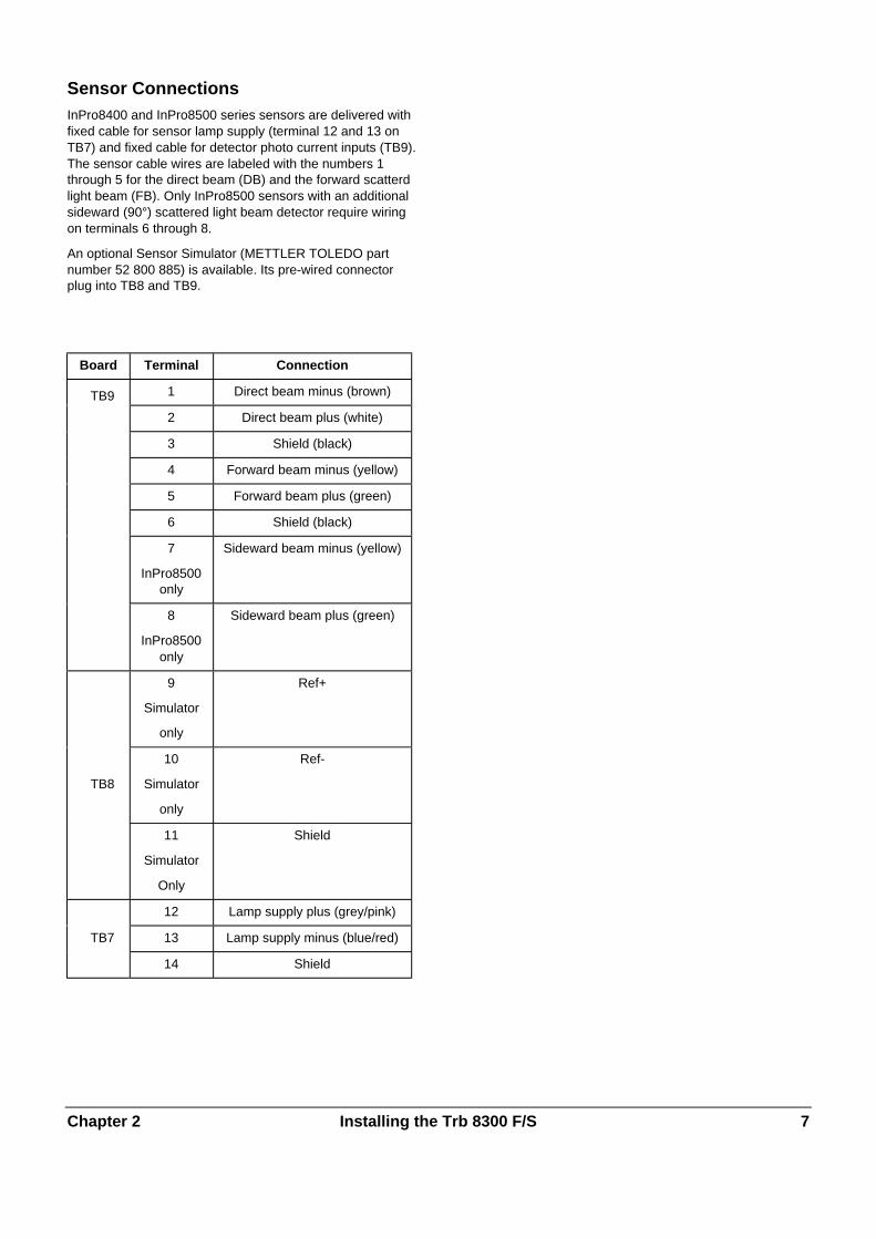
Sensor ConnectionsInPro8400 and InPro8500 series sensors are delivered withfixed cable for sensor lamp supply (terminal 12 and 13 onTB7) and fixed cable for detector photo current inputs (TB9).The sensor cable wires are labeled with the numbers 1through 5 for the direct beam (DB) and the forward scatterdlight beam (FB). Only InPro8500 sensors with an additionalsideward (90°) scattered light beam detector require wiringon terminals 6 through 8.
An optional Sensor Simulator (METTLER TOLEDO partnumber 52 800 885) is available. Its pre-wired connectorplug into TB8 and TB9.
Board Terminal Connection
TB9 1 Direct beam minus (brown)
2 Direct beam plus (white)
3 Shield (black)
4 Forward beam minus (yellow)
5 Forward beam plus (green)
6 Shield (black)
7
InPro8500only
Sideward beam minus (yellow)
8
InPro8500only
Sideward beam plus (green)
9
Simulator
only
Ref+
TB8
10
Simulator
only
Ref-
11
Simulator
Only
Shield
12 Lamp supply plus (grey/pink)
TB7 13 Lamp supply minus (blue/red)
14 Shield

Chapter 2 Installing the Trb 8300 F/S 8
Other ConnectionsEach connection terminal and terminal block are labeled bynumber. The following tables identify each connection.
Board Terminal Connection
1 Do not use !
2 Return Parameter Set A, Band HOLD
3 Do not use !
4 Parameter Set B
TB2 5 Do not use !
6 HOLD
7 Parameter Set A
8 RS232 ground
9 RS232 receive
10 RS232 transmit
11 Do not use !
12 Return Parameter Set C
13 Parameter Set C
14 Do not use
TB3 15 Analog mA output 4 +
16 Analog mA output 3 +
17 Analog mA output -
18 Analog mA output -
19 Analog mA output 2 +
20 Analog mA output 1 +
TB5 1 Alarm, normally closed
2 Alarm common
3 Alarm, normally open
4 Wash, normally closed
5 Wash, common
6 Wash, normally open
TB6 7 Limit 1, normally closed
8 Limit 1, common
9 Limit 1, normally open
10 Limit 2, normally closed
11 Limit 2, common
12 Limit 2, normally open
Discrete Inputs
Discrete (digital) inputs (TB2-4,6,7 and TB3-13) allowexternal dry isolated contacts to pull their +5V logic level tocommon (TB2-2 and TB3-12) to provide discrete controlaction within the Trb 8300 F/S. This control may be used tohold the current (mA) outputs (see Chapter 4 Set HOLDMode) and to select one of three Parameter Sets .
CAUTION: Route wiring to discrete inputs away frompower or switching circuits and provide shielding to anearth ground at the far end of the cable.
Current (mA) Outputs
Connections for current outputs are on TB3. Note thatconnections use common terminal (18) for current outputs 1and 2 and common terminal (17) for current outputs 3 and 4.Current outputs are self-powered and have a maximum loadcapacity of 500 ohms.
CAUTION: Do not connect current outputs to circuitssupplying power. They are already powered.

Chapter 2 Installing the Trb 8300 F/S 9
INITIAL START UP
When power is first supplied to the Trb 8300 F/S, a messagesimilar to the following will be displayed:
* * * * * * * * * * * * * * * * * * * * M E T T L E R T O L E D O T r b 8 3 0 0 F / S v X . X X * * * * * * * * * * * * * * * * * * * *
The second line indicates the instrument main softwareversion.
After a first time start-up of a factory-new transmitter, theinstrument goes into a language menu after powering-up.Select your menu language - english, german or french.Then the instrument automatically goes to the Factory Datamenu in which you have to type in or download the sensorspecific calibration coefficients.
See “USING THE DISPLAY AND KEYPAD” in CHAPTER 3:GETTING STARTED to make yourself familiar with the basicoperations to navigate through the Factory Data menu.
Caution: Before starting measurements the sensorcalibration data have to be entered into the transmitteror must be downloaded into the transmitter via theRS232 interface.
For detailed calibration instructions, see Chapter 5, FactoryData Menu.
After initialization, the display will go to measurement mode.
Display Contrast AdjustmentDepending on ambient lighting and temperature conditions,some adjustment of the LCD display contrast may beneeded. Allow the instrument to warm up to operatingconditions before making an adjustment. Loosen the twocaptive front panel screws and lift the front panel off. Using afine screwdriver, adjust the small potentiometer on the leftside below the display to obtain the desired contrast.Replace the front panel.

Chapter 3 Getting Started 10
CHAPTER 3: GETTING STARTED
Please read this chapter for an overview of the Trb 8300F/S. It will help you understand the operating system andhow to use the display and keypad for data entry.
The following chapters provide detailed information on usingthe Trb 8300 F/S:
Chapter 4: Using Menus – understanding the menusystem, options, and configuration for your applications.
Chapter 5: Calibrations – understanding the different typesof calibrations available, factory calibration, processcalibration, and multi point calibrations.
For help diagnosing and resolving measurement problems,see Chapter 6: Troubleshooting.
OPERATING MODES
The Trb 8300 F/S has two operating modes:
• Measure – used to present measurement data; theinstrument will usually be in this mode.
• Menu – used to set up the system for your specificapplications and access all other operational features.
Measure ModeThree Parameter Sets can be configured in the Trb 8300F/S. In display mode, the measurement of the activeParameter Set (P-Set) is displayed.
P-Sets
Parameter Sets (P-Sets) are termed A through C. In each P-Set the instrument can be configured according to therequirements of a specific application. Each configurationincludes calibration, ranging of current outputs, definition ofsetpoints, and wash intervals and lengths. If the applicationchanges the corresponding P-Set can be retrieved, modifiedand saved again if necessary. This feature is extremelyhelpful if the sensor is installed in a pipe in which differentprocess liquids or process requirements have to bemonitored.
Measurement Units
The Trb 8300 F/S accommodates the followingmeasurement units:
• FTU – Formazin Turbidity Units
• NTU – Nephelometric Turbidity Units
• EBC – European Brewery Convention
• ppm – Parts per million
• g/l – grams per liter
with 1 FTU = 1 NTU = 0.25 EBC = 2.5 ppm = 0.0025 g/l
The turbidity values FTU, NTU or EBC are used if theturbidity of the process liquid is measured on a Formazinbased scale.
ppm or g/l is used when the undissolved solid content hasbeen determined by an alternative measurement, i.e. drymass measurements of grab samples or offline oil in watermeasurements.
The factory adjusted factor of 2.5 (1 FTU = 2.5 ppm) resultsfrom a representative measurement with diatomaceous earthas turbidity reference substance.
Menu ModeMenu mode allows you to set up the Trb 8300 F/Sspecifically for your applications.
The Main Menu consists of many sub-menus in a loop,which can be scrolled through for easy access. These sub-menus allow you to:
• Define Parameter Sets
• Calibrate the system
• Define current (mA) outputs
• Define limit setpoints and wash intervals
• Save/Retrieve Parameter Sets
• Reset different configurations
• Define Security levels
• Perform diagnostic functions
• Define your dialog language
• Configure less commonly used unit functions
• Enter sensor specific factory calibration coefficients

Chapter 3 Getting Started 11
Each menu may consist of one or more screens, or pages,where you define the desired settings.
The remainder of this chapter describes how to use thekeypad and display to define settings and enter informationin menu mode.
The next chapter, Chapter 4: Using Menus, details thecontent of each menu.
USING THE DISPLAYAND KEYPAD
The Trb 8300 F/S operating system is very straightforward,but understanding a few rules will make it easier to navigate.
DisplayThe four-line display provides read-out of measurement dataas well as all menu screens and data entry fields.
Most display information and prompts are self-explanatory,for further assistance press «Help» and page down to readthe message. Press «Help» again to return to the originalscreen.
If an up or down arrow is shown on the right side of thedisplay, then more screens of information are available.
A flashing value in the display mode indicates a setpoint forthat measurement has been exceeded. A high alarmcondition is indicated by “>” after the value. A low alarmcondition is indicated by “<”.
A flashing “H” on the display indicates that the transmitter isin HOLD mode. A flashing “ProCal” in the measurementdisplay indicates that a Process Calibration has been startedand is waiting to be finished (see Chapter 5: Calibrations).Example display:
M e a s u r e m e n t P - S e t A ( P r o c e s s 1 ) F W : 1 0 . 2 F T U P r o C a l S W : 1 0 . 2 F T U H
A letter before the measurement unit indicates a multiplier.The units multipliers are:
• m (milli) = multiply value by 0.001 (10-3)
• _ (units) = multiply value by 1
KeypadThe keypad consists of 9 function keys and 11 alphanumericentry keys.
«Menu (exit)»
Press «Menu (exit)» to access the menu mode. Press«Menu (exit)» again to exit the menu mode.
«Page Up» / «Page Down»
Press «Page Down» to move to the next screen of infor-mation (if any). Press «Page Up» to move to the previousscreen of information (if any). Additional screens areindicated by an up or down arrow on the right side of display.
When finished with a data entry screen, press «PageDown» to go to the next one.
«Help»
Press «Help» to view more information or instructionsregarding the current screen or data entry field.
Press «Page Up» or «Page Down» as necessary to viewthe entire message. Press «Help» again to return to theoriginal screen.
«Enter»
Press «Enter» to select a menu option, to select an optionfrom a list, to complete an alphanumeric entry, or move tothe next data entry field.
Arrow keys
The four arrow keys function as follows:
• «�» – press to view the next item in a list of options.
• «�» – press to view the previous item in a list of options.• «�» – press to move the cursor left in a line of text or
numbers (may also move cursor to the previous field).• «�» – press to move the cursor right in a line of text or
numbers (may also move cursor to the next field).
Alphanumeric keys
The alphanumeric keys are multi-functional. For example,the «1» key can be used to type the letters “A, B, C” in eitherupper or lower case, as well as the numeral “1”
Repetitive presses of the same key produce the differententries. Using the «1» key as an example:
• first press = A
• second press = B
• third press = C
• fourth press = a
• fifth press = b
• sixth press = c
• seventh press = 1
then the sequence repeats.

Chapter 3 Getting Started 12
Notes:
The «0» key will yield the following characters: / = : ( ) 0
The «-» key will yield the following characters:. - + ^ _ ! $
If another letter from the same key is desired, the «�» arrowkey must be used to move the cursor to the next position inthe data entry field.
When a different key is pressed, the cursor automaticallymoves to the next position.
If a lower case letter is selected, the next key pressed willbegin the sequence with the lower case.
The «�» and «�» arrow keys can be used to scroll throughthe entire alphabet.
If the Trb 8300 F/S is expecting a numeric entry, the firstpress will yield the number on the key.
Data EntryIn menu mode, each line of the display presents an optionfollowed by a data entry field.
If a colon “:” follows the field name, use the «�» and «�»arrow keys to scroll through a list of options.
If an equal sign “=” follows the field name, use thealphanumeric keys to enter the required information. (SeeAlphanumeric Keys above.)
When the desired option is selected or the alphanumericentry complete, press «Enter» to move the cursor to thenext field. (When the last field on a screen has beencompleted, pressing «Enter» will return the cursor to the topof the screen.)
If the menu consists of more than one screen of fields, press«Page Down» to continue.
Chapter 4 Using Menus 13
CHAPTER 4: USING MENUS
INTRODUCTION
After installation and entry of sensor factory calibration dataare complete, use the menu system to set up the Trb 8300F/S for your measurements.
First, set up the Parameter Set for each application. Then gothrough the rest of the menus for calibration and to set anyoutputs, setpoints, relays and other functions as necessary.Menu selections are automatically saved as you make them,although on exiting menus you can restore previous settings.
If desired, photocopy the Measurement Parameters Recordform provided in Appendix B to record the menu optionsselected.
After all menu options have been set, return to display modeto view measurement readings.
MAIN MENU
The Main Menu is used for all instrument functions exceptthe actual display of measurements. The following sub-menus are available from the Main Menu:
• Parameter Set – define measurement unit and name of P-Set.
• Calibration – select and perform the appropriatecalibration routine for your measurement. This is onlynecessary if you do mot want to work with the factorycalibration.
• mA Outputs – scale current outputs, and define HOLDmode and type of signal filtering.
• Relays – define limit setpoints, type (high, low), alarmrelay action, and wash cycles.
• Save/Recall – activate a P-Set by recalling it or save yourcurrent settings to another P-Set.
• Reset – return settings to default values.
• Security – enable password protection.• Diagnostic – access a series of diagnostic testing
routines.• Language – select your dialog language (English,
German or French)• Factory data – enter the sensor factory calibration
coefficients
• Other Menus – access to less commonly used menus.
Set Date/Time – enter date and time.Set Unit Name – enter a descriptive name for thisinstrument.
Lost Passwords – retrieve lost passwords.RS232 Set-up – format the Data outputcommunication parametersPrint Config – print current set-up information via theRS-232 port.
Software Revs – display revision of installedsoftware.Service Only – for use by METTLER TOLEDOService personnel only.
AccessTo access the Main Menu, press «Menu (exit)». If security isactive, a prompt for a password will appear.
Press the «�» or «�» key to step through the main Menu.Press «Enter» to select a menu.
NOTE: Access to menu functions can be passwordprotected for security. If you are locked out, you can stillreview settings but not change them. Press anyalphanumeric key as the (wrong) password and press«Enter» to review menu settings.
ExitAfter completing all data entry for one menu option:
• Press «Page Up» until you return to the Main Menu toselect another menu option; or
• Press «Menu (exit)» twice to save settings, exit the menusystem and return to display mode.
• If no keys are pressed for 5 minutes, the Measure modewill resume automatically and settings will be saved.
To exit menus and discard any changes made:
• Press «Menu (exit)» once and then press «1» to exit themenu system, revert to the prior menu settings, and returnto the display mode.

Chapter 4 Using Menus 14
PARAMETER SET MENU
Parameter SetThree different Parameter Sets may be defined in thesystem memory. Each Parameter Set definition will beidentified by a letter (A through C) which will become a lineon the display in the normal measuring mode and othermenus as P-Set.
SensorThe designation “FW” indicates that you a currently using aMETTLER TOLEDO f or w ard scattering light sensor, seriesInPro8400. The designation “FW/SW” indicates that you acurrently using a METTLER TOLEDO combinedf or w ard/ s ide w ard scattering light sensor, series InPro8500.
UnitsThe Trb 8300 F/S accommodates the followingmeasurement units:
• FTU – Formazin Turbidity Units
• NTU – Nephelometric Turbidity Units
• EBC – European Brewery Convention
• ppm – Parts per million
• g/l – grams per liter
with 1 FTU = 1 NTU = 0.25 EBC = 2.5 ppm = 0.0025 g/l
The turbidity values FTU, NTU or EBC are used if theturbidity of the process liquid is measured on a Formazinbased scale.
ppm and g/l is used when the undissolved solid content hasbeen determined by an alternative measurement, i.e. drymass measurements of grab samples or offline oil in watermeasurements.
The factory adjusted factor of 2.5 (1 FTU = 2.5 ppm) resultsfrom a representative measurement with diatomaceous earthas turbidity reference substance.
NameEach Parameter Set can be given a custom name for easieridentification (up to eight alphanumeric or symbolcharacters). If a name is not entered, the Parameter Set willdefault to "none". The name may be overwritten as desired.
Note: See Chapter 3: Getting Started for instructions onusing the alphanumeric keys
To exit the Parameter Set menu see Chapter 4: Usingmenus.
Press «Menu (exit)» to go to the Measure Mode beforeaccessing the Calibration Menu.
FACTORY DATA ANDCALIBRATION MENU
METTLER TOLEDO InPro 8400/8500 sensors are factorycalibrated with Formazin turbidity solutions. On initial start-upof the measuring system the corresponding sensorcalibration data have to be entered into the transmitter. Thisdata is found on the sensor calibration sheet as well as onthe corresponding sensor compact disk.
Caution: Before starting measurements the sensorcalibration data have to be entered into the transmitteror must be downloaded into the transmitter via theRS232 interface.
For detailed calibration instructions, see Chapter 5. Correctstart-up and calibration as well as the understanding ofspecial calibration routines are absolutely necessary foraccurate measurements.
MILLIAMP (mA) OUTPUTS MENU
The 0/4-20 mA Outputs Menu is used to assign currentoutputs to measurements and define any necessary options.Furthermore HOLD Mode and Signal Filters for all fouroutputs are defined.
NOTE: Outputs are programmed to fulfill requirementsof NAMUR NE43. This means that in an over-rangecondition, the outputs will be set to 20.5 mA. In anunder-range condition the outputs will be set to 0 mA or3.8 mA (if low value is set to 4 mA).
Use the «�» and «�» arrow keys in the mA Output menu toselect mA-Output # ( = number), then press «Enter» tocontinue with setting up one of the current outputs.
Four current outputs are provided. Each output can beprogrammed to operate as a normal (i.e., linear), bi-linear,auto-range, or logarithmic output and to send a 22 mA signalif a system failure is detected.
See Chapter 2: Installing the Trb 8300 F/S for connectioninformation.

Chapter 4 Using Menus 15
mA Output #Select Signal (for InPro8500 sensors only)
Use the «�» and «�» arrow keys to select the desiredsignal. Select FW (forward) to assign the turbidity value ofthe forward scattered light sensor to one of the mA outputs.Select SW (sideward) to assign the turbidity value of the 90°scattered light sensor to one of the mA outputs. Press«Page Down» to continue.
mA output #
Use the «�» and «�» arrow keys to select the desiredoutput (1 through 4), then press «Enter» to continue withset-up for that output. Complete all set-up parameters forone output before starting another.
To set up the next output, press «Page Up» until you returnto the initial current output screen and then select anothercurrent output number.
Scaling TypeThe following types of output scaling are available: normal,bi-linear, auto-range, and logarithmic.
Normal scaling provides a linear 4 mA (or 0 mA) to 20 mAoutput. Low and high measurement values can be entered tocorrespond to those outputs.
Bi-linear scaling provides two scaling ranges for a singlelinear strip chart: usually a wide measurement range at thehigh end of the scale, and a narrower range with highresolution at the low end.
In addition to entering low and high values, a mid-rangescaling value must be defined. For example, a user maywant to monitor a particle breakthrough into the liquid phaseduring a liquid/solids separation process. Measurements arenormally in the range of 5-20 FTU but during a particlebreakthrough, a range of up to 200 FTU is desirable.Settings for the low, mid and high values might be 5, 20 and201 FTU, to give convenient plotting on a 10-division stripchart.
Auto-Range scaling provides two ranges of output. It isdesigned to work with a PLC or two points of a multipointstrip chart recorder to meet the same needs as bi-linearscaling above.
Two separate settings are used, one for the high limit of thehigh range and one for the high limit of the low range, for thesingle 0/4-20 mA signal. The low value is always zero.
For the particle breakthrough example above, with risingconcentration, the 0/4-20 mA signal would go from 0-100%for 0-20 FTU, decrease to 10% , then go 10-100% for 20-200 FTU. Thus both 0-20 and 0-200 FTU ranges may berecorded on the same chart using a single signal.
Logarithmic scaling provides an output for use withlogarithmic chart paper. A high value and the number ofdecades must be entered. The low value is defined by theother two settings. For example, a high value of 1000 ppmwith 3 decades would give a range of 1–10–100–1000 ppm
Low Value(signal level)Select 4 mA or 0 mA as the low value of the output signal.
0/4 mA(scaling limit)Enter the measurement value that will correspond to 4 mA(or 0 mA).
Whenever the measurement is equal to this number, theoutput signal will be set to its minimum value. Whenever themeasurement is less to this number it will be set to 0 mA or3.8 mA when 4 mA has been selected (NAMUR NE43).
If the output scaling type is auto-range, the low value isalways zero.
Note: Output signals can be "inverted" by setting theminimum value higher than the maximum.
Mid(Bi-linear scaling only)Enter the measurement value that will correspond to themiddle of the range (10 or 12 mA).
20 mA(scaling limit)Enter the measurement value that will correspond to 20 mA.
Whenever the measurement is equal to this number, theoutput signal will be set to its maximum value. Whenever themeasurement is greater than this number it will be set to20.5 mA (NAMUR NE43).
Num of Decades(logarithmic scaling only)Select the number of decades for the scale, from 1 to 6 (e.g.,1 to 100 is two decades).
On failure 22 mAIf the system or measurement fails, the system can failsafeto either 22 mA or not. In the case that the failsafe is set tooff, the output will go to 20.5 mA. This state is displayed asasterisks “*****” on the front panel display.
Current OutDisplays the actual current (mA) being outputted.

Chapter 4 Using Menus 16
SET HOLD MODE
The Set HOLD Mode menu is used to configure the HOLDstate of the transmitter. During configuration and washintervals, the transmitter can remain in the HOLD state forreasons of safety. The output currents are frozen (at lastvalue or at a preset fixed value, depending on theconfiguration), limit and alarm relays are set to their non-activated status. If a meter is on hold, this is indicated by aflashing “H“ on the display.
HOLD state:No HOLD: The transmitter is never set to a HOLD state. It isalways in a live state.
CAUTION: this setting can lead to unintentionalswitching of alarm/ and limit relays as well as tounexpected mA output readings when configuring thetransmitter.
Fix: The current outputs (1-4) are frozen to a defined valuewhen the transmitter goes into the HOLD state.
Fix Value: Enter the mA output value for the HOLD state.
Last: The current outputs are frozen to the last value assoon as the transmitter goes into the HOLD state.
NOTE: The transmitter is also set into the HOLD state if thecorresponding discrete input is activated (see chapter 2,Discrete Inputs). If “No HOLD” has been selected in thesoftware menu, mA-outputs are only frozen at their last valuewhen the digital input activates the HOLD.
FILTER
Filtering stabilizes measurement readings in applicationswith noisy signals. The following options are available:“none” or “Low Pass” Filter.
RELAYS MENU
The Relays Menu is used to define measurement limits,alarm conditions, a wash interval and length. All relays areSPDT (Single Pole Double Throw) types.
CAUTION: The default software settings for the relays,and the descriptions of the relay operations below,assume that the relays are wired in the following manner(see Chapter 2):
Limit 1 to TB6 pins 8 and 9 (normally open)
Limit 2 to TB6 pins 11 and 12 (normally open)
Alarm to TB5 pins 1 and 2 (normally closed)
Wash to TB5 pins 5 and 6 (normally open)
When the measurement value is higher than a high limitvalue or lower than a low limit value, an alarm conditionexists. Limit alarm conditions are indicated by a flashingmeasurement reading when in the display mode. Also, thecorresponding relay is closed when a limit value isexceeded.
The Alarm relay is opened in case of a system or powerfailure.
NOTE: Setpoints are defined for a specific Parameter Set.The active Parameter Set is displayed in the Relay menus .
Select RelayUse the «�» and «�» arrow key to select a Relay (Limit 1 or2, Alarm or Wash), then press «Page Down» to continuewith the set-up for that relay. Complete all set-up parametersfor one relay before starting another.
To set-up the next relay, press «Page Up» until you return tothe initial relay screen and then select another relay.

Chapter 4 Using Menus 17
LIMIT 1 AND 2
Signal (for InPro8500 sensors only)Select FW (forward) to define a limit value for the forwardscattered light sensor. Select SW (sideward) to assign a limitvalue for the 90° scattered light sensor. Press «Enter» tocontinue.
ValueEnter the desired setpoint value in the measuring unitsdisplayed.
DelayA time delay requires the limit value to be exceededcontinuously for a specified length of time before activatingthe relay. Enter the delay time in seconds.
If the condition disappears before the delay period is over,the relay will not be activated.
HysteresisA hysteresis value requires the measurement to return withinthe limit value by a specified percentage before the relay isdeactivated.
For a high setpoint, the measurement must decrease morethan the indicated percentage below the limit value beforethe relay is deactivated. With a low setpoint, themeasurement must rise at least this percentage above thelimit value before the relay is deactivated. For example, ahigh setpoint is set at 100 and the measurement is currentlyabove this value so that the setpoint is exceeded and therelay is activated. If the hysteresis value is 10%, then themeasurement must fall below 90 before the relay isdeactivated.
Enter a percentage value. No greater than 50%.
Set PointSelect high or low. Select Off to disable the Set Point and toavoid relay triggering.
StateThe State setting allows the operator to decide whether therelay will be physically activated or not during normaloperation. If the N.O. state is selected then the relaycontacts will be open when the limit is not exceeded or whenthe power is off (relay deactivated). The relay contacts willclose when the limit is exceeded (relay activated). This isthe default setting. If the N.C. state is selected then therelay contacts will be open when the limit is exceeded andwhen power is off (relay deactivated). The relay contacts willbe closed when the measurement is within the limits (relayactivated). This assumes that the contacts are wired asdescribed at the start of the relay section.
ALARM
The alarm relay is activated in case of system or powerfailure.
DelayA time delay requires the alarm state to exist continuouslyfor a specified length of time before activating the relay.Enter the delay time in seconds.
If the alarm condition disappears before the delay period isover, the relay will not be activated.
StateThe State for the Alarm relay can not be changed. The relaywill always be activated and the contact is open when thereis no alarm. The relay contact will close when there is analarm or when the power fails or is shut off.
Use alarm if mA outputs are under-/over-rangeIf one of the defined measuring ranges (see Chapter 4, mAOutput #) is exceeded, the Alarm relay can be activated.Select yes or no.
WASH
The Wash relay is used to activate an appropriate cleaningdevice for the sensor.
IntervalEnter the time between two wash cycles in hours. Thesmallest possible value is 0.010 hr (36 seconds). Thegreatest possible value is 999.9 hours. The Wash relay willbe activated when the interval time has been counted down.Enter 0.000 hr for deactivating the wash function. Press«Enter».
Depending on HOLD state settings, the instrument will gointo the HOLD state when a wash cycle has been started(see chapter 3, HOLD state).
Wash timeEnter the time which is needed for a washing cycle inseconds. The greatest possible value is 600 seconds. Press«Enter». The wash relay will be activated for the lengthdefined here plus a fixed post delay time of 20 seconds.After this time the instrument will leave the HOLD state - ifactivated.

Chapter 4 Using Menus 18
StateThe State setting allows the operator to decide whether therelay will be physically activated or not during normaloperation. If the N.O. state is selected then the relaycontacts will be open when the wash is off or when thepower is off (relay deactivated). The relay contacts will closewhen wash starts (relay activated). This is the defaultsetting. If the N.C. state is selected then the relay contactswill be open when the wash is on or when power is off (relaydeactivated). The relay contacts will be closed when thewash is off (relay activated). This assumes that the contactsare wired as described at the start of the relay section.
SAVE/RECALL MENU
In the previous sections all settings for a certain applicationhave been defined in one Parameter Set (P-Set A throughC) and have been automatically saved.
In this menu you can copy the current settings to anotherParameter Set or you can recall another Parameter Set, i.e.when the application changes.
Another Parameter Set can be recalled in the followingmenus or by using the corresponding discrete input (seeChapter 2, other connections).
SelectSelect Save if you want to copy the current settings of aParameter Set to another one. This is helpful if you want toduplicate your current settings as an initial state for anotherParameter Set. Select Recall if you want to activate a certainParameter Set. Press «Page Down».
P-SetSelect the Parameter Set you want to save or recall. Press«Enter».
RESET MENU
The Reset Menu is used to clear user programming andreturn settings to their default values; for the entire system,for single Parameter Sets, or Calibration settings of theactive Parameter Set.Note: The sensor factory data can not be cleared via theReset Menu. If you connect the transmitter to anothersensor, the factory data have to be entered as described inChapter 5, Factory Data and Calibration.
Use the «�» and «�» arrow keys to select the desiredoption to reset, then press «Enter». The available optionsare: “System”, “P-Set”, and “Cal”.
SystemA system reset will:
• Clear and disable all relays, setpoints, and mA outputs inall P-Sets
• Clear all Calibration Settings in all P-Sets.• Set the serial port to 38.4K baud and even parity. The data
output is turned off.Note: A system reset will neither clear the sensor factorydata nor change the unit number.
Press Page Down to reset the system.
P-SetA P-Set reset will:
• Clear and disable all relays, setpoints, and mA outputs inthe active P-Set
• Clear all Calibration Settings in the active P-Set.• Set the serial port to 38.4K baud and even parity. The data
output is turned off.Note: A system reset will not clear the sensor factory data.
Press Page Down to reset the active P-Set.
CalA Cal reset will clear all calibration settings of the active P-Set.
Note: A system reset will not clear the sensor factory data.
Press «Page Down» to rest calibration settings of the activeP-Set.

Chapter 4 Using Menus 19
SECURITY MENU
The Security Menu is used to prevent unauthorized changingof parameters. Users can be locked out of all menufunctions, locked out of calibration only, or locked out of allmenus except calibration. Without the correct numericpassword, the user will only be able to view the menus.
A master password is required to change any passwords,lockout options, or to enable/disable the security program.Two user passwords can be defined.
The initial master and user passwords are set to a default of00000.
Note: It is highly recommended to acivate the "Lock CalOnly" feature to prevent unauthorized changing of thesensor factory calbration data in the "Factory Data"menu. Unintentional changes of Factory Data will lead tofalse measurements.
Go to …Use the «�» and «�» arrow keys to select the desiredsecurity option, then press «Enter». The available optionsare: Change Lockout, Change Password, Lockout Statusand Lost Passwords.
To select another option after completing any of theseoptions, press «Page Up» to return to this screen and select.
Change LockoutEnter the master password to change any of the securitylockout options.
Lockout
If lockout is enabled, users must enter their password to gainaccess to the menus. If disabled, no passwords will berequired.
User 1
Select the desired lockout for User 1. The available lockoutoptions are: “Lockout All”, “Lock Cal Only”, and “Open CalOnly”.
User 2
Select the desired lockout for User 2.
Change PasswordUse to change any of the passwords.
Which password to change
Select the desired user or master password.
Master Pass
Enter the master password to proceed.
New password
Enter a new 5 character password and press «Enter». Youwill then be prompted to re-enter the password to confirm it.
Lockout StatusThe status fields are for display only.
Lockout is
Displays whether security lockout is disabled or enabled.
User 1
Displays current lockout option for User 1.
User 2
Displays current lockout option for User 2.
Time since last access in menus
Displays the elapsed time since the menus were lastaccessed by any user.
DIAGNOSTICS MENU
During measurements there are diagnostic testing routinesrunning in the background of the transmitter software inorder to alarm the user in case of any system failure.
In addition, there is a Diagnostic Menu used to run a seriesof diagnostic testing routines to verify the operation of thesystem components, including: transmitter, sensor, mAoutputs, serial port, display, keypad, inputs and relays.
Use the «�» and «�» arrow keys to select a component totest, then press «Enter». The indicated test will beperformed and the results displayed. Press «Enter» toperform the next test.
To test another component, press «Page Up» to return tothe Diagnostic Menu and select the next component.
After completing the desired diagnostics, press «Menu(exit)» twice to exit the menu system and return to displaymode.
CAUTION: Some diagnostic tests may interrupt normaloperation of current outputs and relays and could upsetrelated processes.
See the appropriate section below for information regardingthe specific diagnostic tests.
Chapter 4 Using Menus 20
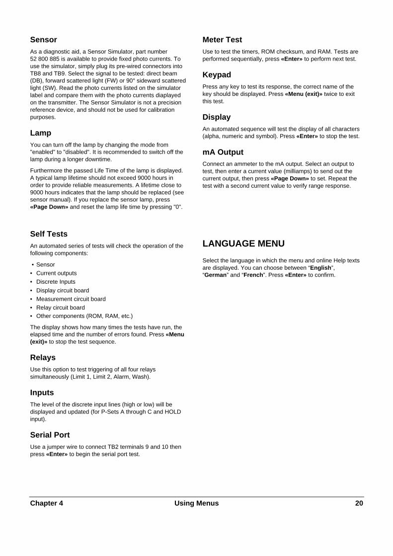
SensorAs a diagnostic aid, a Sensor Simulator, part number52 800 885 is available to provide fixed photo currents. Touse the simulator, simply plug its pre-wired connectors intoTB8 and TB9. Select the signal to be tested: direct beam(DB), forward scattered light (FW) or 90° sideward scatteredlight (SW). Read the photo currents listed on the simulatorlabel and compare them with the photo currents diaplayedon the transmitter. The Sensor Simulator is not a precisionreference device, and should not be used for calibrationpurposes.
LampYou can turn off the lamp by changing the mode from"enabled" to "disabled". It is recommended to switch off thelamp during a longer downtime.
Furthermore the passed Life Time of the lamp is displayed.A typical lamp lifetime should not exceed 9000 hours inorder to provide reliable measurements. A lifetime close to9000 hours indicates that the lamp should be replaced (seesensor manual). If you replace the sensor lamp, press«Page Down» and reset the lamp life time by pressing "0".
Self TestsAn automated series of tests will check the operation of thefollowing components:
• Sensor
• Current outputs
• Discrete Inputs
• Display circuit board
• Measurement circuit board
• Relay circuit board• Other components (ROM, RAM, etc.)
The display shows how many times the tests have run, theelapsed time and the number of errors found. Press «Menu(exit)» to stop the test sequence.
RelaysUse this option to test triggering of all four relayssimultaneously (Limit 1, Limit 2, Alarm, Wash).
InputsThe level of the discrete input lines (high or low) will bedisplayed and updated (for P-Sets A through C and HOLDinput).
Serial PortUse a jumper wire to connect TB2 terminals 9 and 10 thenpress «Enter» to begin the serial port test.
Meter TestUse to test the timers, ROM checksum, and RAM. Tests areperformed sequentially, press «Enter» to perform next test.
KeypadPress any key to test its response, the correct name of thekey should be displayed. Press «Menu (exit)» twice to exitthis test.
DisplayAn automated sequence will test the display of all characters(alpha, numeric and symbol). Press «Enter» to stop the test.
mA OutputConnect an ammeter to the mA output. Select an output totest, then enter a current value (milliamps) to send out thecurrent output, then press «Page Down» to set. Repeat thetest with a second current value to verify range response.
LANGUAGE MENU
Select the language in which the menu and online Help textsare displayed. You can choose between “English”,“German” and “French”. Press «Enter» to confirm.

Chapter 4 Using Menus 21
OTHER MENUS
The Other Menu is used to access less commonly usedfeatures, including:
• Set Time/Date
• Cal Table
• Set Unit Name
• Lost Passwords
• RS232 Set-up
• Print Configuration
• Software Revisions• Service Only
Set Date/TimeUse to enter the correct date and time. Note that the internalclock does not run when power is off. It is only aconvenience for setting the dates of calibration.
Time
Enter time in hours, minutes and seconds (hh:mm:ss).
Date
Enter date in month, day and year format (mm/dd/yy).
Cal TableUse this function to read-out the single calibrationcoefficients for the Factory, Multipoint and or Processcalibration. This is a view-only menu. You can use a spreadsheet to visualize the single calibration curves.
Set Unit NameThis feature is especially useful when more than one unit isused. Enter the name or location of this unit (up to 20characters).
The unit name is displayed whenever exiting menus andappears in configuration printouts.
Lost PasswordsTo recover lost passwords, record the codes displayed onthe screen and then call the METTLER TOLEDO CustomerService for assistance (phone +41 1 736 2525).
RS232 set-upThe RS232 Menu is used to format the data outputcommunication parameters (baud, parity, etc.).
For detailed digital communications with regards to MainProgram Software Upgrades see Chapter 7.
Data output: Selected to on, the current measurement witha time stamp can be recorded via the RS232 using a printeror a communication software package on a PC when thisbecomes available.
Print ConfigurationA computer or printer can be used to record all set-upinformation (P-Sets A through C). If a device is connected tothe RS232 output, press «Enter» to print. If the RS-232output is connected to a computer, then a program likeHyper Terminal can read all of the set-up information.
Software RevsDisplays the engineering revision numbers of the currentlyinstalled system circuit boards (main, measurement, displayoption).
Service OnlyThese are service password protected functions for use byMETTLER TOLEDO Service Personnel only.

Chapter 5 Calibrations 22
CHAPTER 5: FACTORY DATA AND CALIBRATIONS
INTRODUCTION
A METTLER TOLEDO forward or combinedforward/sideward scattered light turbidity system consists ofa transmitter type Trb 8300 F/S and a InPro sensor type8400 or 8500. InPro8400/8500 sensors are available indifferent sizes and with different process connections.InPro8400/8500 sensors are directly installed in a processpipe (see also sensor manual InPro 8400/8500, part number52 800 883 (English), 52 800 879 (German), 52 800 884(French)).
For maximum user flexibility, sensor and transmitter are notmatched with each other. Each sensor is factory calibrated.The specific calibration data is provided on a calibrationsheet and on a compact disk (CD), both included in thesensor package. When starting up the system, these sensorspecific calibration data have to be entered into thetransmitter. This step is mandatory before starting ameasurement. User and application defined calibrationroutines allow a later calibration for fine tuning the system ifnecessary.
CALIBRATION TYPES
In each Parameter Set (Set A to C) three different types ofcalibration are possible: Factory Calibration (FactoryData), Multipoint Calibration and Process Calibration.
Factory Calibration (Factory Data)This is the basic calibration for a specific sensor. It varieswith every sensor. Consequently the sensor calibration datahave to be entered into the transmitter for starting up thesystem or if a sensor is replaced by another one or if thetransmitter is replaced by another one. The FactoryCalibration data are automatically loaded into all threeParameter Sets (A, B, and C) for immediate use.
Caution: when starting a new transmitter the first time,the user is asked to enter the sensor specific calibrationdata. Measurements are only possible after thisoperation step. Unauthorized changing of the FactoryCalibration data can lead to false measurements. Userscan be locked out from this menu point by using thesecurity features of the Trb 8300 F/S (see chapter 4Security Menu).
Sensor specific calibration data result from a multiple pointfactory calibration performed with Formazin to guaranteebest linearity for the whole measuring range.
Process Calibration/Zero PointAdjustmentThis type of calibration is an online calibration, where theuser enters the Process Cal menu and saves the currentturbidity reading. The user then takes a “grab sample” of theprocess to measure it against a laboratory instrument to geta reference turbidity measurement.
Before the Process Calibration can be completed, thelaboratory reference turbidity measurement must be enteredinto the transmitter. During the period when the grab sampleis being analyzed the transmitter retains the measuredturbidity signal reading in memory. The transmitter returns todisplay the measurement and functions normally and themessage “ProCal” is displayed. The user can go into anymenu except the calibration menu. Upon returning to theonline transmitter, the user re-enters the Process Calibrationmenu. The menu allows the user to adjust the slope oroffset with the new value that is to be entered. The next stepallows the user to enter the reference turbidity value that wasobtained in a lab. Also shown is the stored value that thetransmitter saved during the initial entry into ProcessCalibration. Note the current reading may be very differentthan the stored value due to the time that has elapsed whileobtaining the laboratory measurement. Finishing the menuentries completes the Process Calibration. The ProcessCalibration routine is also used for zero point adjustment. Ifthe zero point solution is inside sensor flow-cell, the zeropoint is adjusted via the offset adjustment. Of course, takinga grab sample is not necessary here.
If the user previously completed a Multipoint calibration(see below), the user is reminded when entering the Processcalibration menu that this has occurred. Also depending onwhether the slope or offset was adjusted, the Multipointcalibration curve will also be adjusted. A user will most likelygo into a Process Calibration after a Factory Calibration or aMultipoint calibration to fine tune the process.
Chapter 5 Calibrations 23
Multipoint CalibrationThis calibration is intended to be used for offline calibrationswith a turbidity standard – typically Formazin. The sensorhas to be removed from the pipe first in order to pour thedifferent calibration solutions into the sensor body. In normaloperation it is not necessary to perform a MultipointCalibration because the InPro 8400 and 8500 sensors arealready factory calibrated with Formazin. However, if anotherturbidity standard is used it might be useful to perform aMultipoint calibration. For additional user flexibility, amultipoint calibration can be performed if turbidity is notmeasured on a Formazin scale (FTU, NTU or EBC) but on appm or g/l scale with the respective process liquid itself.Consequently the real concentration of these cal sampleshas to be determined by alternative analytical techniques.
FACTORY DATA MENU
When starting the transmitter Trb 8300 F/S the first time theuser is automatically guided into the Factory Data menu. Forlater use (e.g. when a sensor is replaced by another one) theFactory Data Menu can be accessed via the main menu.
Note: To prevent the Factory Data menu fromunauthorized access it can be protected using thesecurity features of the Trb 8300 F/S (see Chapter 4SECURITY MENU).
The sensor specific factory calibration data can be enteredinto the transmitter in two alternative ways:
- Manual input via the keypad of the Trb 8300 F/S- Automatic download via the RS232 interface of the
Trb 8300 F/S
Manual InputCaution: Make sure the sensor calibration sheet you usehas the same serial number as the one printed on thesensor. Mismatching of sheets and sensors leads tofaulty measurements.
Go to the Factory Data menu in the Main Menu and press«Enter» if you have not been guided there automatically incase you powered up the transmitter the first time.
Sensor Type
Select FW (forward) for InPro 8400 sensor, select FW/SWfor forward and 90° scattered light measurements (combinedmeasurements) with InPro8500 sensors. Press «Enter».
FTU # 1…12
Enter the corresponding turbidity values which are printed onthe sensor calibration sheet via the alphanumeric keys.Press «Enter».
FW
Type in the corresponding "Forward" (FW) coefficient for thecurrent turbidity which is printed on the sensor calibration aswell. Press «Enter».
SW (InPro8500 sensors only)
Type in the corresponding "Sideward" (SW) coefficient forthe current turbidity which is printed on the sensor calibrationas well. Press «Enter».
After the entry of the last coefficient press «Page down» toaccept your inputs or "Page-up" to modify them again.
The transmitter is now programmed with the specificfactory calibration data and ready to be used forturbidity measurements based on the Formazin scale inevery Parameter Set. If you later on perform a Processor Multipoint Calibration, the original factory calibrationdata can be re-activated by the “Use” command in theCalibration menu (see Chapter Calibration Menu).
Automatic downloadCaution: Make sure the start-up CD you use has thesame serial number as the one printed on the sensor.Mismatching of CD´s and sensors leads to faultymeasurements.
The program is started directly from the CD. The programruns on computers using Windows98 or later.
Procedure
1. For a new transmitter being started for the first time:exit the Factory Data menu by pressing «Menu (exit)»two times.For previousely calibrated transmitters: go into themeasuring mode.
2. Make sure the Trb 8300 is configured forcommunications and connected to a serial port of yourcomputer (see also the port wiring diagram in Chapter 7,a RS232 interface cable is available from METTLERTOLEDO, part number 58 080 111)Press «Menu (exit)». Select “Other Menus” using the«�» or «�» key, then press «Enter». Select “RS232Set-up” using the «�» or «�» key, then press «Enter»again. Set Baud = 38.4K, Par = None, Data Output =Off, if these parameters are not already set like this.
Chapter 5 Calibrations 24
3. Your computer must have Microsoft.NET FrameworkPackage. This is included on the CD. To install it:
a. Double click on the dotnetfx.exe icon in your CDdirectory.
b. Answer yes to “Would you like to installMicrosoft.NET Framework Package?”
c. Answer next to “Welcome to the .NET setup wizardwhich will guide you through the installationprocess.”
d. Answer OK to “Installation of Microsoft.NETFramework vXXXXX is complete.”
4. Your computer must have the DownloadCalPointsprogram. This is included on the CD. To install it:
a. Insert the Mettler-Toledo Turbidity CD into yourcomputer.
b. Using Windows Explorer, find the CD and locate theprogram “Setup.exe”.
c. Double click on “Setup.exe” to start the installationprogram.
d. The setup program will guide you through theinstallation. For each screen you can accept thedefault parameters by pressing the “Next” button.
e. After the installation is complete you may closeWindows Explorer.
5. From the Windows Start button select “Program”, then“Download Calibration Points”, then“DownloadCalPoints”.
6. Using the menus of the DownloadCalPoints program,select “Communications”.
7. Setup the communication port. Select the com port thatyou are using. Set the parameters as 38,400 baud, 8bits, no parity, flow control = None, and 1 stop bit. PressOK when done.
8. Press the “Open File” button. Find the data file thatcontains the calibration data. This file is located on theCD and has the extension “.csv”. Press the “Open”button to load the file.
9. The DownloadCalPoints program will display thecalibration to transfer this information to your meter.
10. Press the “Send” button to transfer this information toyour computer.
The transmitter is now programmed with the specificfactory calibration data and ready to be used forturbidity measurements based on the Formazin scale inevery Parameter Set. If you later on perform a Processor Multipoint Calibration, the original factory calibrationdata can be re-activated by the “Use” command in theCalibration menu (see Chapter Calibration Menu).
CALIBRATION MENU
Select Use, Process or Multi Point and confirm with «Enter».
USEHere you can select which type of Calibration shall be activein the current Parameter Set.
Factory – uses the sensor calibration data provided on thecorresponding sensor CD or calibration sheet. This is thedefault mode after programming the Factory Data (seeChapter Factory Data Menu).
Process – uses the current Process Calibration data, ifpreviously set by the user. For the InPro8500, the forwardand side calibration need to be set independently
Multi Point – uses the current MultiPoint Calibration data, ifpreviously set by the user. For the InPro8500, the forwardand side calibration data are simultaneously set.
PROCESSProcess Calibration is intended to be used for onlinecalibrations. It is applicable after both, Factory datacalibration and Multipoint calibration to update the calibrationdata when measuring against a grab sample value.
Typically use of Process Calibration:
- The clearest (= zero turbidity) process liquid is flowingthrough the sensor body and the instrument reading is notzero (zero point adjustment)
- Routine updates of inline measurements against offlinelaboratory measurements for quality assurance reasons.
- The optical setup of your laboratory turbidimeter isdifferent to the setup of the InPro sensors, i.e. a differentwavelength range or scattering angle.
Having started a Process Calibration you are being asked topress «Page Down» to save the current reading. Thisshould happen at the same time that you take the grabsample from the process or you know that the clearest liquid(zero point solution) is inside the pipe if you want to adjustthe zero point.
The transmitter goes back to the measurement modereminding the user that a Process Calibration has beenstarted by a flashing “Process Cal” in display.
When you know the concentration of the grab sample, enterthe Process Calibration Menu a second time: quick accesscan be done by pressing «Page Down» when the instrumentis in the measuring mode. For zero point adjustmentswithout taking a sample this steps follows immediately afterthe first step.
Adjust: Choose Slope or Offset depending on whether themeasuring curve shall be adapted to the grab sample valueby changing the offset or the slope value of the curve. Press«Page Down» to continue.

Chapter 5 Calibrations 25
Note: It is recommended to choose the Offset if the grabsample value is close or equal to zero or the sensorflow-cell is filled completely with the zero point solution.A repeated Process Calibration is possible if youexperience that an earlier change of slope or offset hasnot resulted in the desired measurements.
Value then Page-down to cal: Enter the known value ofyour grab sample and press Page-down. The instrumentperforms the Process Calibration and goes back to themeasuring mode.
A Process Calibration can be stopped without changes bypressing «Menu (Exit)» when you have entered the ProcessCalibration Menu the second time.
Multipoint CalibrationInPro8500 sensors:
Different to the Process Calibration routine, a Multi PointCalibration calibrates both channels – forward and 90° -at the same time to achieve an identical measuringvalue. This results from the use of the Formazin scale.By definition, a certain Formazin concentration providesa unique instrument reading independently from thescattering angle, i.e. a Formazin solution of 40 FTU (orNTU) shall produce a reading of 40 FTU on bothchannels. This concept is maintained with othercalibration solutions as well.
The Multipoint Calibration option is intended to be used foroffline calibrations. For the weld-in sensor versionsInPro8400T and InPro8400N only a process calibration ispossible.
Caution: Before removing the sensor from process pipe,make sure the process pipe is completely empty and thepipe and the surface of the sensor have cooled down toambient temperature. Any escape of hot medium underpressure may cause damage to material/equipment orinjury to persons. It is not necessary to remove opticalarms, cables or any other parts from the senor bodyitself.
Close one end of the sensor by installing a blind flange andgasket or a rubber stopper. Place the sensor vertically on abench, and pour in the calibration solutions . If HOLD modeis activated, the transmitter will go into HOLD when enteringthe Multipoint Calibration menu.
A Multipoint Calibration is performed when you are usingsamples with known turbidity or suspended particleconcentration, i.e. when turbidity standards like Formazin areused or the concentration of the samples has beendetermined by a reference measurement.
Due to different light scattering characteristics of differentsamples it is not possible to predict when a Multipointcalibration with more than two points is necessary. Three ormore point calibrations can become necessary with samplesshowing a very high optical density or when you experiencea divergence from linear signal output.
A Multipoint Calibration is reasonably performed in theconcentration range you are going to measure in yourprocess.
The recommended way to perform a Multipoint Calibration iswith samples prepared by defined dilution of a stock solution.This has the advantage that only the concentration value ofthe stock solution has to be determined by a referencemethod. The concentration of the other samples results fromthe defined dilution.
For example: half the volume of a stock solution with 100ppm suspended solids is diluted with the same volume ofclear solvent to get a concentration of 50 ppm. Half of thevolume of this 50 ppm solution is diluted by the same volumeof clear solvent to get a concentration of 25 ppm. Thefollowing four point calibration is performed with 0, 25, 50and 100 ppm.
Typically 100-1000 ml of stock solution is necessary toperform an offline calibration, depending on the volume ofthe sensor body in use.
Note: During dilution and measurement make sure youare working with homogeneous samples. Sedimentationof particles has to be avoided by stirring the solution.
Type
Select 2, 3, 4 or 5 point depending on how many differentsamples you are going to use. Press «Page-down» tocontinue.
Cal Point
Pour the solution with the lowest concentration into thesensor body first. Make sure the liquid covers the opticalwindows inside the sensor body completely and no airbubbles are sticking on the windows. In order to eliminatelight from the surrounding cover sensor body with a blackpiece of paper or something similar. On the second line ofthe display you will see the current reading. Enter the knownmeasured value of your sample and press «Page-down». Amessage shows up indicating that calibration is in progress.
FW / SW (InPro8500 sensors only)
The displayed FW (forward) and SW (sideward) are thephoto current ratios of forward (sideward) and direct beam.These values are unitless and are part of the cubic splinelinerazitaion calculation. If desired, the user can record theminto a spread sheet to look at the curve fit. This provides arepresentation of the actual computation curves and couldbe used for reference by the user.
Press «Page-down» to continue with the next calibrationpoint.
Rinse the sensor with clear solvent and dry the sensor withair or sterile lab wipes. Proceed to calibrate the second pointwith the second lowest concentration.
Typically the last point of a Multipoint Calibration isperformed with the stock solution itself.
Chapter 5 Calibrations 26
You can stop a Multipoint Calibration at any time by pressingthe «Menu (Exit)» key and then the «1» key .
Upon completion of the Multipoint calibration you are beingasked to accept this calibration with «Page-down» or tocheck and/or modify it with «Page-up». With «Page-up» youhave the possibility to re-calibrate a single point, adjust thecurrent turbidity reading or to accept a calibration point.Press «Page-up» until you see the calibration point youwould like to change.
Do, OK, Adjust
«Do» is the only option you have during the first calibrationcycle. In the modifying cycle you use «Do» to recalibrate asingle point. Rinse the sensor with clear solvent and proceedto calibrate this point with the new concentration.
Select «Adjust» to adjust a single calibration point withoutdoing a calibration with a defined turbidity solution.
Select «OK» if you do not want to modify the currentcalibration point and get to the next one.
If you have performed a successful calibration cycle you arebeing asked to press «Enter» to execute your Multipointcalibration in the active Parameter Set. With the «Use»command described above you still can select if you want towork with your calibration or the original factory calibration. Afollowing Process Calibration is executed on the currentcalibration in use.
Re-install the sensor again in your process.
Chapter 6 Maintenance & Troubleshooting 27
CHAPTER 6: MAINTENANCE & TROUBLESHOOTING
MAINTENANCE
Front Panel CleaningClean the front panel with a damp soft cloth (water only, nosolvents). Gently wipe the surface and dry with a soft cloth.
For Technical Support and repair information contact yourlocal METTLER TOLEDO dealer.
TROUBLESHOOTING CHECKLIST
If the equipment is used in a manner not specified by METTLER TOLEDO, the protection provided by the equipment may beimpaired.
Review the table below for possible causes of common problems:
Problem Possible Cause
Display is blank. No power to Trb 8300 F/S.
Blown fuse.
LCD display contrast set incorrectly.
Hardware failure.
Display shows flashing “H” Transmitter is currently in HOLD mode
Display shows flashing “ProCal” A Process Cal has been started.
Display shows ****** Calibration settings not suitable for current media
Incorrect measurement readings. Wrong sensor wiring.
Unit programmed with wrong sensor factory calibration data.
Sensor window fouling or coating.
Process pipe not filled completely.
System needs calibration.
Hardware failure.
Measurement readings not stable. Low Pass filter off.
Gas bubbles in process media.
Process pipe not filled completely.
Sensor failure.
Displayed measurement reading is flashing. Limit value is in alarm condition (limit value exceeded).
Cannot change menu settings. User locked out for security reasons.
Data not sent out to serial port. Serial port miswired.
Baud rate and/or parity set incorrectly.

Chapter 7 Maintenance & Troubleshooting 28
ERROR MESSAGES
Following is a list of error messages, their meaning, and possible causes.
Message Meaning / Possible Cause
FW Over Range
SW Over Range
DB Over Range
Forward, Side, or Direct Beam signal is too high. The flow-cellis not filled with a liquid.
A/D Cal Failed The main analog to digital converter failed to perform periodictemperature self-calibration, but can still performmeasurements. Ship transmitter back for repair.
A/D Vref Failed The main analog to digital voltage reference source failed.Ship transmitter back for repair.
A/D Failed The main analog to digital converter failed and is not able tomake measurements. Ship transmitter back for repair.
DB Signal Low The Direct Beam signal is below usable limit. The turbidity istoo high or the sensor is not connected.
Lamp Error The unit could not set a nominal lamp current, due to possiblehardware failure. Ship transmitter back for repair.
Lamp Over Range Lamp voltage is too high. This could be caused by lampburnout or broken or misconnected wire or sensor lamp armcable is not connected to transmitter
Lamp Under Range Lamp voltage is too low, due to short circuit or hardwaremalfunction. Ship transmitter back for repair.
Check Lamp Cal Lamp circuit needs to be recalibrated. Ship back transmitterfor repair.
Lamp Off Lamp has been turned off.
Check Measure PCB Measurement board is missing, failed, or not properlyconnected. Ship transmitter back for repair.

Chapter 7 Upgrade 2 9
CHAPTER 7: UPGRADE
UPGRADES
There is software for various functions located in the Trb8300 F/S. The need for field upgrade is likely to occuronly with the Main Program and Measurement software.
Main program Software UpgradeOver the life of the instrument, it may become desirableto upgrade the main operating software of the Trb 8300F/S to a newer version. The main operating softwarerevision number can be displayed by stepping throughthe menus: Other Menus/Software Revs/Main Program.
The main program software is changed by downloadingthe new operating file using METTLER TOLEDOThornton utility program Max95.exe. It runs on computers
using Windows95 or later and occupies about 0.7 MB ofhard disk space.
NOTE: Not all menus of the Max95 program arefunctional—use only those needed for the upgrade asdescribed in the procedure below.
A cable is required with connector for the computer’sRS232 port. Most computers use a DB9 connector asshown. Tinned leads at the other end connect to the Trb8300 F/S screw terminals.
Because the memory chip containing operating softwarealso contains extensive instrument calibration data, it isnot practical to upgrade software by replacing thememory chip.
Trb 8300 F/S to computer RS232 port wiring
Procedure1. Record all the configuration settings and the serial
number of the Trb 8300 F/S unit being upgraded.
2. Confirm that the Trb 8300 F/S is configured forcommunications. Press «Menu (exit)» and use «�»in Other Menus to display “RS232 Set-up”. Set Baud= 38.4K, Par = Even, Data Output = Off, if they arenot already set this way.
3. Connect the Trb 8300 F/S to the computer RS232port as shown above.
4. From e-mail or floppy disk, copy the programMax95.exe and the new Trb 8300 F/S software filee.g. 43714_14 into a convenient folder or desktop ofthe computer.
5. Run Max95.exe by double clicking it in WindowsExplorer and ignore any small incidental windowsthat may open.
6. Click to open “Communication” menu and “RS-232Functions” and select “Gateway Port Set-up”.
7. Select Port – COM 1 (or other port if you are usinganother).
8. Select Baud Rate – 38400.
9. Select Data Bits – 8.
10. Select Parity – Even.
11. Uncheck Enable Polling. Leave other settings asfound (Flow Control – Xon/Xoff, Stop Bits – 1).
12. Click OK and observe “Connected” in the lowerborder of the window when communications arefunctioning.
DB9 Connector tocomputer (view of endof cable that plugs into
computer)
15
69
12345678910
Trb 8300 FSTB2 terminals
GroundReceiveTransmit
Chapter 7 Upgrade 3 0
13. Click on the integrated circuit button (Program Unit,4th from right) on the tool bar.
14. Select Units to Program – One Unit and enter 1 inthe box. Leave Unit Type at Main.
15. Click “Read” and locate the new Trb 8300 F/Ssoftware file and click OK. The new software versionwill be loaded into computer memory.
16. Click ”Program”. Loading to the Trb 8300 F/S willtake several minutes. Allow to run until 100% isdisplayed.
17. Restore the serial number of the unit using theappropriate command in section RS232Communications.
18. Disconnect the RS-232 wiring from the Trb 8300 F/S.
19. If necessary, reconfigure the unit with the settingsrecorded in step 1.

Chapter 8 Accessories and Spare Parts 31
CHAPTER 8: ACCESSORIES AND SPARE PARTS
ACCESSORIES
Description Part Number
IP66 field-type enclosure for wall mounting 52 800 867incl. 5 pcs PG11 cable gland and front door with windowDimensions: H=200, W=250, L=230 mm H=7.87", W=9.84", L=9.10")Material: Stainless steel
RS 232 interface cable 2 m (6 ft.) 58 080 111
SPARE/REPLACEMENT PARTS
Description Part Number
10-Terminal plug-in connector (TB2 and TB3) 52 800 251*
6-Terminal plug-in connector (TB5 and TB6) 52 800 252*
Fuse, 0.5 A slow blow, 5 x 20 mm (Little fuse 215.500 or equivalent) 52 800 253*
Panel mounting screws (6-32 x 7/16”, 4 required) 52 800 254
Screws for front panel (2 required) 52 800 255
Retaining washers for front panel (2 required) 52 800 256
Liquid crystal display module (order mounting standoffs separately) 52 800 257
Display standoffs (4 required for display above) 52 800 258
*Recommended Spare parts

Appendix A Menu Trees 3 2
APPENDIX A: MENU TREES
The following menu trees illustrate the general sequenceof settings available in the Trb 8300 F/S.
The screens below will appear after pressing «Menu»only if security has been enabled. Otherwise pressing«Menu» accesses the Main Menu directly, as shown onthe following pages.
ENTER PASSWORDA password is needed
to enter the menusPassword = *****
EXIT MENUS?Press 0 to go back
1 to discard/exitany key to save/exit
Menu (exit) key
Menu (exit) key
Enter key
MeasurementP-Set A (None )FW: xxxx FTUSW: yyyy FTU
MeasurementP-Set A (None )FW: xxxx FTU
Correct Password
Wrong Password
ENTER PASSWORDInvalid password, Youcan view menus only
Press Enter if OK
MAIN MENUView Only
MAIN MENUNormal operation
When exit menus
Sensor factory data menu
Language options:EnglishDeutschFrançais
Appears only when starting a new meter out of the box
No sensor cal data!Enter sensor factorydata. Press Enter.
Appears only when starting a new meter out of the box
LanguageSelect language use then press EnterLanguage: English
↑,↓
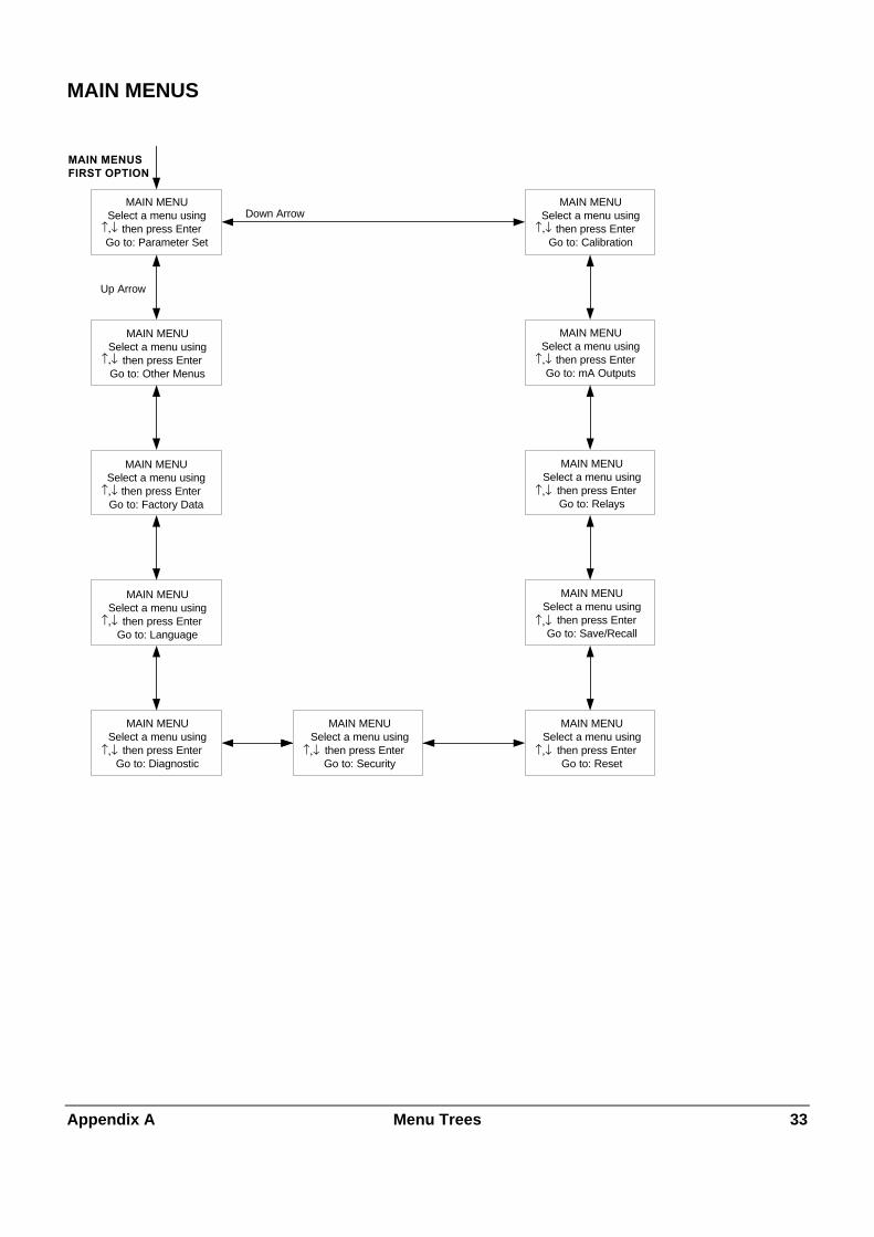
Appendix A Menu Trees 3 3
MAIN MENUS
MAIN MENUSFIRST OPTION
MAIN MENUSelect a menu using then press Enter
Go to: Parameter Set
MAIN MENUSelect a menu using then press Enter
Go to: Other Menus
MAIN MENUSelect a menu using then press EnterGo to: Factory Data
MAIN MENUSelect a menu using then press EnterGo to: Language
MAIN MENUSelect a menu using then press EnterGo to: Diagnostic
MAIN MENUSelect a menu using then press Enter
Go to: Reset
MAIN MENUSelect a menu using then press EnterGo to: Save/Recall
MAIN MENUSelect a menu using then press Enter
Go to: Relays
MAIN MENUSelect a menu using then press EnterGo to: mA Outputs
MAIN MENUSelect a menu using then press EnterGo to: Calibration
Down Arrow
Up Arrow
↑,↓
↑,↓
↑,↓
↑,↓
↑,↓
↑,↓
↑,↓
↑,↓
↑,↓
↑,↓
MAIN MENUSelect a menu using then press Enter
Go to: Security↑,↓
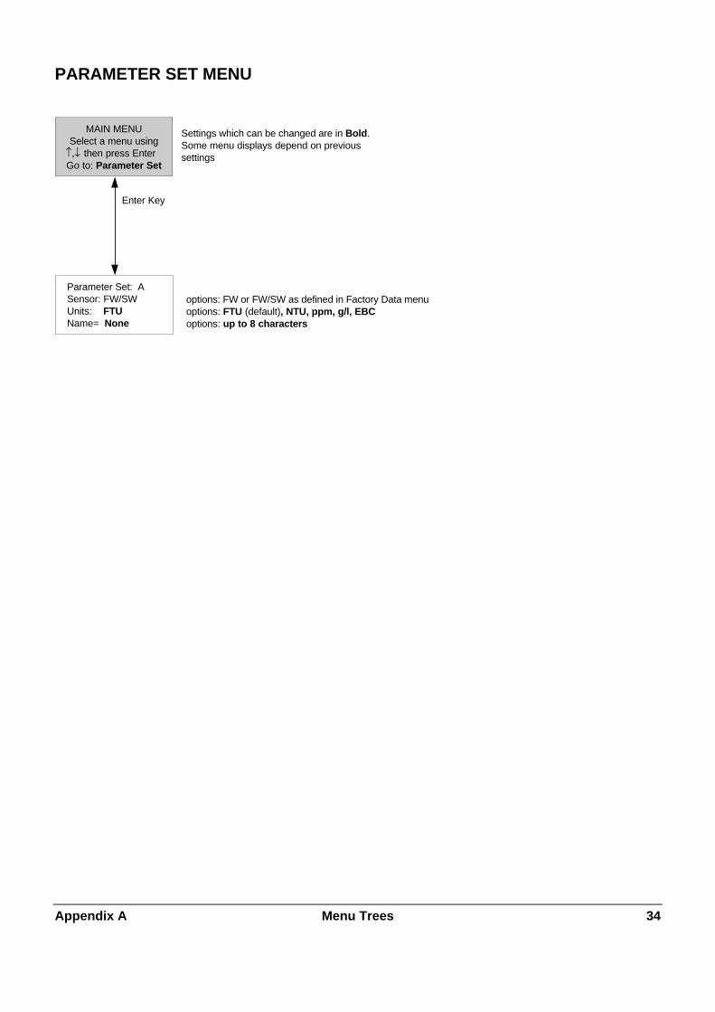
Appendix A Menu Trees 3 4
PARAMETER SET MENU
MAIN MENUSelect a menu using then press Enter
Go to: Parameter Set
Settings which can be changed are in Bold.Some menu displays depend on previous settings
Parameter Set: ASensor: FW/SWUnits: FTUName= None
options: FW or FW/SW as defined in Factory Data menuoptions: FTU (default), NTU, ppm, g/l, EBCoptions: up to 8 characters
Enter Key
↑,↓

Appendix A Menu Trees 3 5
CALIBRATION MENUS
CALIBRATIONP-Set A (None )Select, Press Enter:xxxxx Options:
Process Multi PointUse
Options: FactoryProcess Multi Point
PROCESS CALP-Set A (None )FW Read: XXXXX FTUPage-Down to do cal
MULTI PT CALP-Set A (None )Type: 5 - Point FTUPage-Down when set
MeasurementP-Set A (None)FW: XXXXX FTU ProCal
PROCESS CALP-Set A (None )Adjust: offsetPress Page-Down
PROCESS CALStored: 0.000 FTU FWValue then Page-Downto cal: XXXXX FTU
PROCESS CAL DONE
↑
↑
↓↑
↓
↑
↓
Please wait Point 1: XXXXX FTU
Reading: XXXXX
↓
↑
Point 1: XXXXX FTUReading: XXXXX
Page-Down when done
MULTI PT CALis complete. Press Enterkey to execute.Page-up to modify
MULTI PT CALFW: XXXXX SW: XXXXX
Cal Point 2: XXXXXCalibrate: DO
↑
↓
Saving Setup Data .....
Multi Point
Process
Page-Down
Saving Setup Data .....
PROCESS CALP-Set A (None )Signal to be calibrated:FW
↑
↓
Enter Key
USE CALP-Set A (None )Select, Press Enter:FACTORY
P-Set A (None)Factory has been
selectedPress the ENTER key
If m and/or p is emptydisplay: “Not available”
↓
↑
MULTI PT CALP-Set A (None )Remove sensor fromprocess. Press Enter
***
Note: For FW sensors (SW) will not appear.
MAIN MENUSelect a menu using then press EnterGo to: Calibration
↑,↓for InPro8500: FW and SW are calibrated simultaneously
Up arrow will not appear on first Multi Point
“Please wait” will disappear after calculation
Options: 2-point3-point4-point5-point
MULTI PT CALReading: XXXXX FTU
Cal Point 1: XXXXXCalibrate: DO ↓
↑Options: OKDOADJUST
Options: offsetslope
Option: Stored: 0.000 FTU SW for InPro8500 only
flashing ProCal remindsthe user that a ProcessCal has been started
Options: FW, SW
appears only with InPro8500 sensors

Appendix A Menu Trees 3 6
mA OUTPUTS MENUS
mA OUTPUT #1Range 1 Settings:4mA = 0.000 (FTU)20mA = 0.000 (FTU)
MAIN MENUSelect a menu using
Go to: mA Outputs
mA OutputsSelect a menu using
↑,↓ then press EnterGo to: xxxxx Options: mA Output # (default), Set Hold Mode, FilteringOu
mA OUTPUT #1P-Set: A (None )
Type: NormalLow Value: 4mA
mA OUTPUT #1On failure 22mA:Yes
Current Out = 22.00mA
mA OUTPUT #1P-Set A (None )
4mA = 0.000 (FTU )20mA = 0.000 (FTU )
mA OUTPUT #14mA = 0.0000 (FTU )Mid = 0.000020mA = 0.0000
mA OUTPUT #120mA = 0.0000 (FTU )
Num of Decades:1more
SIGNAL FILTERINGFilter: None
Bi-Linear
mA OUTPUT #1On failure 22mA: Yes
Current Out = 22.00mA
AutoRange
mA OUTPUT #1Range 2 Settings:4mA = 0.000 (FTU)20mA = 0.000 (FTU)
mA OUTPUT #1On failure 22mA: Yes
Current Out = 22.00mA
Logarithmic
mA OUTPUT #1On failure 22mA: Yes
Current Out = 22.00mA
Normal
Options: 1, 2, 3, 4
only for InPro8500 sensors
Options: FW, SW
Options: Normal, Bi-Linear AutoRange, LogarithmicOptions: 4 mA (default), 0 mA
Filtering
Filter Options:None (default)LowPass
SET HOLD MODEP-Set A (None )Hold state:xxxxx
mA Output #
SET HOLD FIXP-Set A (None )Fix Value: 22.0 mA
On failure: 22mA Options: Yes, No
On failure: 22mA Options:Yes, No
Set Hold Mode
Options:No Hold (default)FixLast
Enter Key
↑
↑
↓
mA OUTPUT #1P-Set: A (None )Select signal: FW
↑
↓
↑
↓
↑
↓
↑
↑
↓
↑
↑
↓
↑
↑
↓
↑
↑
↓
↑
↑,↓ then press Enter

Appendix A Menu Trees 3 7
RELAYS MENUS (for InPro8400)
MAIN MENUSelect a menu using
then press EnterGo to:
Alarm Limit1 Limit2
Delay in seconds
WASHP-Set A (None )Interval = 0.00hrWash Time = 0000 sec
WASHP-Set A (None )State = N.O.
ALARMP-Set A (None )Delay = 0000 sec
State: N.C.
Wash
LIMIT1P-Set A (None )State = N.O.
LIMIT2P-Set A (None )State = N.O.
LIMIT1P-Set A (None )Hysteresis = 0.00%Set Point = Off
LIMIT2P-Set A (None )Hysteresis = 0.00%Set Point =Off
RELAY SETUPP-Set A ( None )Select Relay:xxxxx
Options:Limit 1 (default)Limit 2AlarmWash
Interval in hourWash time in seconds
LIMIIT 1P-Set A (None )Value: 0.000 FTUDelay: 0000 sec
LIMIIT 2P-Set A (None )Value: 0.000 FTUDelay: 0000 sec
Relays
Enter Key
ALARMUse alarm if mA
outputs are under /over range: No
Alarm options: Yes, No
↑,↓
↑
↓
↑
↓
↑
↓
↑
↓
↑ ↑ ↑
↓
↑
↓
↑ ↑
Set point options:Low (default)HighOff
State options:N.O. (default)N.C.
State options: N.C. (default)N.O.
State options: N.O. (default)N.C.

Appendix A Menu Trees 3 8
RELAYS MENUS (for InPro8500)
MAIN MENUSelect a menu using
then press EnterGo to:
Alarm Limit1 Limit2
Delay in seconds
WASHP-Set A (None )Interval = 0.00hrWash Time = 0000 sec
WASHP-Set A (None )State = N.O.
ALARMP-Set A (None )Delay = 0000 sec
State: N.C.
Wash
RELAY SETUPP-Set A ( None )Select Relay:xxxxx
Options:Limit 1 (default)Limit 2AlarmWash
Interval in hourWash time in seconds
LIMIT 1P-SET A (None )Select signal: FWValue: 0.000 FTU
LIMIT 2P-SET A (None )Select signal: FWValue: 0.000 FTU
LIMIT 1P-SET A (None )Delay: 0000 secHysteresis= 0.00 %
LIMIT 2P-SET A (None )Delay: 0000 secHysteresis= 0.00 %
LIMIT 1P-SET A (None )Setpoint: LowState: N.O.
LIMIT 2P-SET A (None )Setpoint: LowState: N.O.
Relays
Enter Key
ALARMUse alarm if mA
outputs are under /over range: No
Alarm options: Yes, No
↑,↓
↑
↓
↑
↓
↑
↓
↑
↓
↑ ↑ ↑
↓
↑
↓
↑ ↑
Set point options:Low (default)HighOff
State options:N.O. (default)N.C.
State options: N.C. (default)N.O.
State options: N.O. (default)N.C.

Appendix A Menu Trees 3 9
SAVE/RECALL MENUS
MAIN MENUSelect a menu using
then press Enter
Go to: Save/Recall
Select Option: Save, Recall
P-Set options: ABC
P-Set options: ABC
SAVE/RECALLSave or recall aParameter Set.Select xxxxx
RECALLP-Set AEnter to confirm!
SAVEP-Set AErases old settings!Enter to confirm!
P-Set A hasbeen saved.
Press the Enter key
P-Set A hasbeen recalled.
Press the Enter key
SAVE RECALL
Enter Key
Page-Down key
↑,↓
↑
↓
↑ ↑

Appendix A Menu Trees 4 0
RESET MENUS
MAIN MENU
Select a menu using then press Enter
Go to:
System
Reset
RESETSelect a type using
then press EnterReset: xxxxx
RESET SYSTEMP
Only Factory sensor data is still present
In active P-Set only Factory sensor data, mA, relay andRS232 settings are still present
Only Factory sensor data is still presentin this P-Set
ress Page-Down whenready to reset orother keys to quit
The system has beenreset
Press the Enter key
The P-SET A has beenreset
Press the Enter key
Reset Options:P-Set (default)SystemCal
RESET CALPress Page-Down whenready to reset orother keys to quit
Cal has beenreset
Press the Enter key
RESET P-SET APress Page-Down whenready to reset orother keys to quit
Cal P-SET
Enter Key
↑,↓
↑,↓
↑ ↑ ↑
↑

Appendix A Menu Trees 4 1
SECURITY MENUS
VERIFY PASSWORDConfirm new passwordThen press Enter key
New Password = *****
CHANGE PASSWORDWhich password to
change: xxxxxMaster Pass? = *****
CHANGE PASSWORDEnter a new Master
password
New Password = *****
Goto Option: Change Lockout Change Password Lockout Status Lost Passwords
LOCKOUT STATUSLockout is DisabledUser1 Lockout AllUser2 Lockouit All
LOCKOUT STATUSTime since lastchange in meter
setup was 00:36:09
LOCKOUT MENULockout: DisabledUser1: Lockout AllUser2: Lockout All
CHANGE LOCKOUTTo Change lockoutenter the Master
Password = *****
Change Options:Master, User 1, User2
The Master Password hasbeen set
Press the Enter key
Wrong password wasentered
Press the Enter key
Enter Key
CorrectPassword
Wrong password wasentered
Press the Enter key
WrongPassword
Lockout Options: Enabled, Disabled
User Options:Lockout All, Lock Cal Only,Open Cal Only
VERIFY PASSWORDConfirm new passwordThen press Enter key
New Password = *****
CHANGE PASSWORDEnter a new User 1
password
New Password = *****
The Users Password hasbeen set
Press the Enter key
Passwords did notmatch
Press the Enter key
Master
MAIN MENUSelect a menu using then press Enter
Goto : Security
SECURITY MENUSelect option using then press Enter
Goto : xxxxx
User 1, User 2
RECOVER PASSWORDSMaster: ACEGIUser #1: CFILOUser #2: GKOSW
Lost Passwords
↑,↓
↑,↓
↑
↑
↑
↑
↑
↑
↑
↑
↑
↑↑
↑
↓

Appendix A Menu Trees 4 2
DIAGNOSTICS MENUS
MAIN MENUSelect a menu using
Go to: Diagnostic
Go to Option:Sensor, mA Outputs, Display, KeypadMeter Test, Serial Port, Relays, Self tests, Lamp
KEYPAD TESTPress MENU twiceto exitKey Pressed: xx
SERIAL PORT TESTConnect TXD TO RXDon TB2, Press Enterwhen ready
mA OUTPUT TESTmA Output #1Set Output @12.00mAPage-Down to set
TEST MENUSelect a test using
Test: FW signal
DIAGNOSTIC TESTTest: TimersResult: PassedENTER for next test
INPUT TESTIn A=Hi In B=HiIn C=Hi Hold=LowPage-Up to return
DIAGNOSTIC TESTkey 1 = Relays openkey 2 = Relays closedPage-up to return
Test options:FW signalSW signalDB signal
Result: currents in appropriate units
Options:enableddisabled
5 digits for lifetime
mA OutputOptions:1, 2, 3, 4, ALLOutput Option:0< value < 24
DIAGONSTIC MENUSelect a test using
Go to: xxxxxx
Sensor
mA Outputs
Display
Keypad Meter TestTest options:Timers, ROMChecksum, RAM
Result:Passed,Failed
Serial Port
Inputs
Relays
This unit under testTest# 00:00:00
Testing inputs
Self Test
ENTER KEY
ENTER KEY
mA OUTPUT TESTmA Output #1
Set Output @ 12.00mACurrent Set @ 12.00mA
SERIAL PORT TESTTest Passed
ENTER key to repeat
Test options:PassedFailed
then press Enter↑,↓
↑,↓
↑
↑
↑
↑
↑
↑↑
LAMP MENUMode: enabledLife time: xxxxx hPage-Down for more
Lamp
↑
LAMP MENULife time: xxxxx hPress "0" to reset life time
SENSOR TESTFW Signal TestCurrent: xx.x mA
Errors = 0
1111111111111111111111111111111111111111
1111111111111111111111111111111111111111
then press Enter
↑,↓ then press Enter

Appendix A Menu Trees 4 3
LANGUAGE MENUS
MAIN MENUSelect a menu using
Go to:
Language Option:EnglishGermanFrench
Language
LANGUAGESelect language use
Language English
Enter Key
↑,↓ then press Enter
↑,↓ then press Enter

Appendix A Menu Trees 4 4
FACTORY DATA MENUS
MAIN MENU
Select a menu using
Go to: Factory Data
En
for InPro8500 for InPro8400
ter Key
↑,↓ then press Enter
Options: FW/SWFW
........ ........
Sensor factory dataset complete.
Page-down to accept.Page-up to edit.
Sensor factory dataSensor type: FW# of cal point. 24Press Page-Down
FTU #1 xxxxFW: xxxxSW: xxxxPress Page-Down
FTU #1 xxxxFW: xxxxPress Page-Down
Sensor factory dataset complete.
Page-down to accept.Page-up to edit.
No sensor cal data. Entersensor factory data
Press Enter
If Factory Data aredefined the followwingmessage appears
No sensor cal data. Entersensor factory data
Press Enter
Do you want to overwrite sensor data?
If yes pressPage-Down.
Sensor factory dataSensor type: FW/SW
# of cal point: 36Press Page-Down
EXIT MENUS?Press 0 to go back
1 to discard/exit and key to save/exit
EXIT MENUS?Press 0 to go back
1 to discard/exit and key to save/exit
go to measuringmode
go to measuringmode
FTU #12 xxxxFW: xxxxSW: xxxxPress Page-Down
FTU #12 xxxxFW: xxxxPress Page-Down
↑
↓
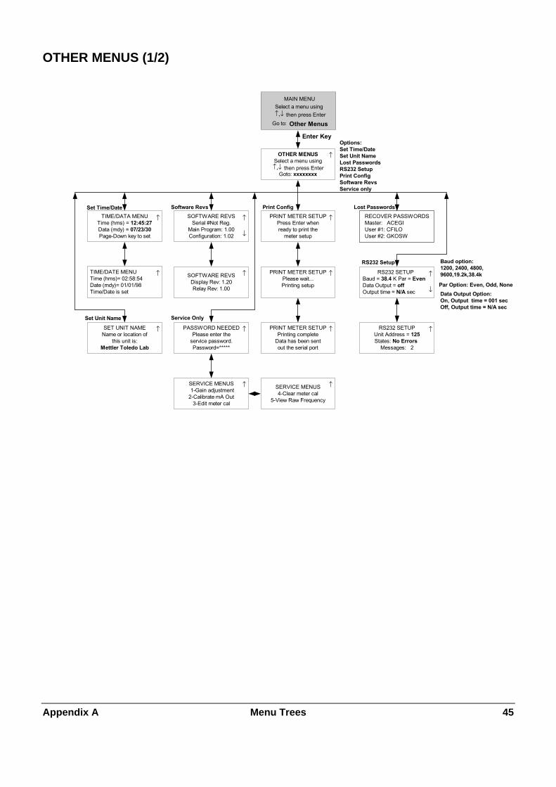
Appendix A Menu Trees 4 5
OTHER MENUS (1/2)
MAIN MENU
Select a menu using
Go to:
RECOVER PASSWORDSMaster: ACEGIUser #1: CFILOUser #2: GKOSW
TIME/DATE MENUTime (hms)= 02:58:54Date (mdy)= 01/01/98Time/Date is set
PRINT METER SETUPPress Enter whenready to print the
meter setup
Options: Set Time/Date Set Unit Name Lost Passwords RS232 Setup Print Config Software Revs Service only
PRINT METER SETUPPrinting complete
Data has been sentout the serial port
PRINT METER SETUPPlease wait...Printing setup
TIME/DATA MENUTime (hms) = 12:45:27Data (mdy) = 07/23/30Page-Down key to set
SOFTWARE REVSSerial #Not Reg.
Main Program: 1.00Configuration: 1.02
SOFTWARE REVSDisplay Rev: 1.20Relay Rev: 1.00
SET UNIT NAMEName or location of
this unit is:Mettler Toledo Lab
OTHER MENUSSelect a menu using
Goto: xxxxxxxx
RS232 SETUPBaud = 38.4 K Par = EvenData Output = offOutput time = N/A sec
RS232 SETUPUnit Address = 125
States: No ErrorsMessages: 2
Baud option:1200, 2400, 4800,9600,19.2k,38.4k
Par Option: Even, Odd, None
Data Output Option:On, Output time = 001 secOff, Output time = N/A sec
Service Only
SERVICE MENUS1-Gain adjustment
2-Calibrate mA Out3-Edit meter cal
Set Time/Date Software Revs Print Config Lost Passwords
Set Unit Name
RS232 Setup
PASSWORD NEEDEDPlease enter the
service password.Password=*****
Other Menus
SERVICE MENUS4-Clear meter cal
5-View Raw Frequency
Enter Key
↑,↓ then press Enter
↑,↓ then press Enter
↑
↑
↑
↑
↑
↑
↓
↑ ↑
↓
↑↑
↑
↑
↑
↑

Appendix A Menu Trees 4 6
OTHER MENUS (2/2)
Mult PT TableNTU: XXXXFW: XXXXSW: XXXX
Mult PT TableNTU: XXXXFW: XXXXSW: XXXX
CAL Table: FactoryP-Set ASelect the typeThen press Enter
Factory TableNTU: XXXXFW: XXXXSW: XXXX
Mult PT Table Factory Table Process Table
OTHER MENUSSelect a menu using then press EnterGoto: CAL TABLE
CAL TABLE
CAL TABLE Options:FACTORYMULTI PTFW PROC
Factory TableNTU: XXXXFW: XXXXSW: XXXX
Process TableNTU: XXXXFW: XXXXSW: XXXX
Process TableNTU: XXXXFW: XXXXSW: XXXX
Press Down Arrow Press Down Arrow Press Down Arrow

Appendix B Set-Up Parameter Record 4 7
APPENDIX B: SET-UP PARAMETER RECORD
MEASUREMENT PARAMETERS RECORD 1/2
Photocopy this form for each Parameter Set programmed into the Trb 8300 F/S.
Unit Name: Date:
Sensor installed:
Model: S/N:
Cable length:
Parameter Set:
Units: Name:
Calibration routine: Calibration solution:
Date of last calibration:
Analog Output 1
Output Type: Range:
On failure set output to 22 mA:
Analog Output 2
Output Type: Range:
On failure set output to 22 mA:
Analog Output 3
Output Type: Range:
On failure set output to 22 mA:
Analog Output 4
Output Type: Range:
On failure set output to 22 mA:
Filter: HOLD mode:
Limit Value 1:
Value: Delay:
Hysteresis: Setpoint :
State:
Limit Value 2
Value: Delay:
Hysteresis: Setpoint :
State:

Appendix B Set-Up Parameter Record 4 8
MEASUREMENT PARAMETERS RECORD 2/2
Wash contact:
Interval: Wash time:
State:
Alarm:
Delay: State:
Use alarm if mA outputs are under/over range:
Passwords
Master: User1 :
User2:
Language:
RS232 Settings
Baud: Parity:
Data output: Output time:
Unit adress:

Appendix C Specifications 4 9
APPENDIX C: SPECIFICATIONS
Power supply 100…240 VAC 25 Watts maximum, 47-63 Hz (part number 52 800 865)
20…32 VDC 25 Watts maximum (part number 52 800 866)
On power loss, all stored values are retained in non-volatile memory without batteries.Clock does not run when power is off.
Sensors 1 input /output (approx. 5 VDC sensor lamp supply) for InPro8400 or InPro8500 opticalsensor (forward or combined forward/sideward (90°) sacttered light principle)
Measurement range selectable between
0…400 FTU (Formazin Turbidity Units)
0…400 NTU ( Nephelometric Turbidity Units)
0…100 EBC (turbidity according European Brewery Convention)
0…1000 ppm
0…1.0 g/l
Transmitter signal accuracy ≤1% of supplied photoelectric current
Repeatability of measured value ≤2%
Resolution 0.01 FTU or 1% of measured value (whatever is bigger)
Parameter Sets Three configurable Parameter Sets (A - C), storable and retrievable via software menu orremote access via digital inputs
Digital Input 4 buffered digital inputs (0-5 V)
– 1 digital input for HOLD function
– 3 digital inputs for activating stored Parameter Sets A-C
System Calibration (Operating modes)
Factory-defined calibration Specific factory-set sensor data can be imported via RS232 interface or manually viakeypad.
Process Calibration Single-point calibration simultaneously with sampling (adjustment of offset or slope, userdefined)
Multipoint Calibration Automatic 2, 3, 4 or 5 point automatic calibration using calibration solutions or definedconcentration in order to linearize the measurement curve.
Preset calibration parameter: Software reset restores calibration data to factory-set sensor data
Password protection Password-protected menu access for different operator levels (Master, User 1 and 2), ableto be activated
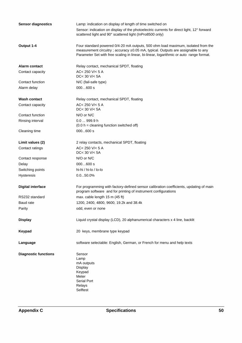
Appendix C Specifications 5 0
Sensor diagnostics Lamp: indication on display of length of time switched on
Sensor: indication on display of the photoelectric currents for direct light, 12° forwardscattered light and 90° scattered light (InPro8500 only)
Output 1-4 Four standard powered 0/4-20 mA outputs, 500 ohm load maximum, isolated from themeasurement circuitry ; accuracy ±0.05 mA, typical. Outputs are assignable to anyParameter Set with free scaling in linear, bi-linear, logarithmic or auto range format.
Alarm contact Relay contact, mechanical SPDT, floating
Contact capacity AC< 250 V/< 5 ADC< 30 V/< 5A
Contact function N/C (fail-safe type)
Alarm delay 000…600 s
Wash contact Relay contact, mechanical SPDT, floating
Contact capacity AC< 250 V/< 5 ADC< 30 V/< 5A
Contact function N/O or N/C
Rinsing interval 0.0 ... 999.9 h(0.0 h = cleaning function switched off)
Cleaning time 000...600 s
Limit values (2) 2 relay contacts, mechanical SPDT, floating
Contact ratings AC< 250 V/< 5 ADC< 30 V/< 5A
Contact response N/O or N/C
Delay 000…600 s
Switching points hi-hi / hi-lo / lo-lo
Hysteresis 0.0...50.0%
Digital interface For programming with factory-defined sensor calibration coefficients, updating of mainprogram software and for printing of instrument configurations
RS232 standard max. cable length 15 m (45 ft)
Baud rate 1200, 2400, 4800, 9600, 19.2k and 38.4k
Parity odd, even or none
Display Liquid crystal display (LCD), 20 alphanumerical characters x 4 line, backlit
Keypad 20 keys, membrane type keypad
Language software selectable: English, German, or French for menu and help texts
Diagnostic functions SensorLampmA outputsDisplayKeypadMeterSerial PortRelaysSelftest

Appendix C Specifications 5 1
Data retention Configuration and calibration data in non-battery supported, non-volatile memory
CE
Emissions EN 55022:1994 Class A ITE emissions
Immunity EN 61326:1997 Measurement, Control and Laboratory Equipment EMC Requirements –Industrial Use
Safety IEC 61010-1 Safety requirements for electrical equipment for measurement,control and laboratory use
US UL 3111-1 Electrical Measuring and Test Equipment
CAN / CSA C22.2, No. 1010.1
Nominal operating conditions
Ambient temperature –10…+55 °C (14 ... 131 °F)
Transport/Storage temp –20…+80 °C (-4 ... 176 °F)
Relative humidity 0…80 % up to 31 °C (88 °F), decreasing linearly to 50 % at 40°C (104 °F)
Enclosure
Alloy ABS-PC, UV and chemically resistant
Assembly Panel mounting, cutout 96 x 96 mm (3.78“ x 3.78“)1/4 DIN
Dimensions H 125 mm, W 114 mm, L 162 mm (H 4.92“, W 4.50, L 6.39“)
Protection sealed face, IP65 (Nema 4X)
Weight Approx. 0.9 kg (2 lbs.)

Appendix D Ratings 5 2
APPENDIX D: RATINGS
Declaration of Conformity
We,
Declare under our sole responsibility that the product:
Trb 8300 F/S Transmitter
to which this declaration relates, is in conformity with the following European, harmonized and published standards at the dateof this declaration:
Emissions:EN 55022:1994 Class A ITE emissions
Immunity:EN 61326:1997 Measurement, Control and Laboratory Equipment EMC
Requirements – Industrial Use
Safety:IEC 61010-1 “Safety requirements for electrical equipment for
measurement, control and laboratory use” incorporatingAmendments Nos. 1 & 2
Testing for compliance was carried out to the following specifications:
Following the provisions of the directives 89/336/EEC Electromagnetic Compatibility
Amendment to the above directive: 93/68/EEC
Low Voltage. Directive 73/23/EEC
Amendment to the above directive: 93/68/EEC
UL RecognitionThornton Inc., 1432 Main Street, Waltham, MA 02451, USA has obtained Underwriters Laboratories’ Recognition for Trb 8300F/S Transmitters. They bear the cULUS recognition mark, signifying that the products have been evaluated to the applicableANSI/UL and CSA Standards for use in the U.S. and Canada.
US UL 3111-1 Electrical Measuring and Test EquipmentCAN/CSA C22.2, No. 1010.1

Appendix E Warranty 5 3
APPENDIX E: WARRANTY
METTLER TOLEDO guarantees the quality of materials and workmanship within a narrow range of manufacturing tolerances,so that the product purchased is free from any substantial deviations from material and manufacturing quality standards. Thewarranty is valid for the period of one year from date of delivery ex works. If within this warranty period, any repair orreplacement should become necessary, and such cause is not due to misuse or incorrect application, please return theproduct, carriage paid, to your appropriate METTLER TOLEDO agency. Repair work will be carried out free of charge. Finaldecision on whether the defect is due to a manufacturing error or to incorrect operation of the product by the customer is madeat the option of the Customer Service department of METTLER TOLEDO. After expiry of the period of warranty, faultyproducts will be repaired or replaced on an exchange basis against payment of the costs involved.

BR Mettler-Toledo Ind. e Com. Ltda., Alameda Araguaia, 451 - Alphaville, BR – 06455-000 Barueri / SP, BrazilTel. +55 11 4166 74 00, Fax +55 11 4166 74 01
CH Mettler-Toledo (Schweiz) AG, Im Langacher, CH – 8606 Greifensee, SwitzerlandTel. 01 944 45 45, Fax 01 944 45 10
D Mettler-Toledo GmbH, Prozeßanalytik, Ockerweg 3, D – 35396 Gießen, GermanyTel. (0641) 507-333, Fax (0641) 507-397
F Mettler-Toledo Analyse Industrielle Sàrl, 30 Bld. de Douaumont, BP 949, F – 75829 Paris, FranceTel. (1) 47 37 0600, Fax (1) 47 37 4626
USA Mettler-Toledo Process Analytical Inc., 299 Washington Street, Woburn, MA 01801, USATel. (781) 939-6300, Fax (781) 939-6390
Mettler-Toledo GmbH, Process Analytics, Industrie Nord, CH – 8902 Urdorf, Tel. 01 736 22 11, Fax 01 736 26 36, www.mtpro.comSubject to technical changes. 12 / 03 © Mettler-Toledo GmbH. Printed in Switzerland. 52 800 880
Related Documents