MEASUREMENT OF ALTERNATING SIGNALS T T R R M M 1 1 ARDETEM – TA CO/07 V1.7x C 11/08 – Any data in this documentation may be modified without prior notice. ® Tel : 04 72 31 31 30 - Fax : 04 72 31 31 31 http://www.ardetem.com - e-mail : [email protected] Route de Brindas - Parc d’activité d’Arbora - N°2 69510 SOUCIEU EN JARREST - FRANCE

Welcome message from author
This document is posted to help you gain knowledge. Please leave a comment to let me know what you think about it! Share it to your friends and learn new things together.
Transcript
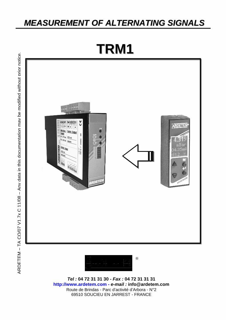
MMEEAASSUURREEMMEENNTT OOFF AALLTTEERRNNAATTIINNGG SSIIGGNNAALLSS
TTRRMM11
AR
DE
TE
M–
TA
CO
/07
V1
.7x
C1
1/0
8–
An
yd
ata
inth
isd
ocu
me
nta
tio
nm
ay
be
mo
difie
dw
ith
ou
tp
rio
rn
otice
.
®
Tel : 04 72 31 31 30 - Fax : 04 72 31 31 31http://www.ardetem.com - e-mail : [email protected]
Route de Brindas - Parc d’activité d’Arbora - N°269510 SOUCIEU EN JARREST - FRANCE

USE 3
1. RECEIPT AND STARTING OF THE INSTRUMENT 32. ORGANISATION OF THE FRONT FACE 33. LIST OF THE MEASURED PARAMETERS 44. ODDNESS OF THE SIGNED PARAMETERS 45. USE OF THE « CUT OFF » 46. LIST OF THE DISPLAYED ERRORS 57. MEANING OF THE VARIOUS ENERGY METERS 5
USE OF THE µCONSOLE8. INTRODUCTION TO THE µCONSOLE 69. INFORMATION RELATING TO THE INSTRUMENT - FEATURES 610. CHOICE OF THE LANGUAGE 611. ACCESS TO THE MAIN MENU 612. READING OF THE MEASURES 7
12-1. Changing of displayed parameter 712-2. Display of the parameter name and unit 712-3. Reading of harmonics 7
13. ANALYSIS OF THE RS PATTERNS 7
PROGRAMMING 8PROGRAMMING BY PC SOFTWARE
1. ACCESS TO THE CONFIGURATION 82. CONFIGURATION OF THE NETWORKS 8
2-1. Choice of the measure network 82-2. Entering of the CT and VT ratios 82-3. Choice of the digital filtering 82-4. Choice of the mode 82-5. Programming of the cosine 82-6. Programming of the « cut off » 8
3. CONFIGURATION OF THE OUTPUTS 9
3.1 Configuration of a relay output 93.2 Configuration of an analog output 11
4. CONFIGURATION OF A DIGITAL OUTPUT (RS) 13
4-1. General information 134-2. Configuration of the output : procedure to be followed 134-3. Addresses of the measures 144-4. Format of the measures 174-5. CRC16 calculation algorythm 19
PROGRAMMING BY THE CONSOLE1. ORGANISATION OF THE MENUS AND SPECIFIC ENTERINGS 202. ACCESS TO THE MAIN MENU 213. CHOICE OF THE LANGUAGE 21

4. MODIFICATION OF THE CONFIGURATION – [ PROGRAM ] 21
4-1. Input parameters - [ INPUT ] 214-2. Parameters of the RS output - [ MODBUS ] 224-3. Parameters of the optional outputs – [ OUTPUT ] 24
5. ZERO RESET OF THE ENERGIES – [ ENRGY ] 26
TECHNICAL FEATURES 27
1. GENERAL FEATURES 272. ELECTRICAL FEATURES 273. POSSIBLE OUTPUTS 294. DIMENSIONS 30
WIRING 31
1. WIRING RECOMMENDATIONS 312. WIRING OF THE POWER SUPPLY 313. WIRING OF A SINGLE-PHASE NETWORK : « 1 PHAS » 324. WIRING OF A 3-PHASE BALANCED NETWORK WITHOUT NEUTRAL : « 3W BAL » 325. WIRING OF A 3-PHASE BALANCED NETWORK WITH NEUTRAL : « 4W BAL » 336. WIRING OF THE RELAY & ANALOG OUTPUTS 337. WIRING OF THE DIGITAL OUTPUT RS485 34
7-1. Wiring RS485 / 422 4 wire 347-2. Wiring RS485 / 422 2 wire 347-3. Termination 34
ANNEXE 1 : READING OF THE HARMONICS BY THE DIGITAL DATA LINK 35
3
USE
1. RECEIPT & STARTING OF THE INSTRUMENT
Check that the instrument configuration (see label on the case side) corresponds to yourorder. In case of servicing or on-line assistance, the instrument’s programme version and itsidentification number will be necessary (they can be read with the µconsole or with the PCprogramme). Latch the instrument on a DIN rail. Connect the power supply (see wiring diagrams),
The ON tension LED lights up. The instrument then starts to measure. It has a standard configuration (unless indicated onyour order). The instrument can now be programmed, preferably before connecting the measure signals. Then connect all signals : see wiring diagrams. The standard communication parameters of the PC software or the digital output are thefollowing : slave number = 250 speed = 9600 bauds without parity 1 stop bit
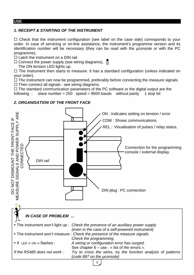
2. ORGANISATION OF THE FRONT FACE
IN CASE OF PROBLEM …
The instrument won’t light up : Check the presence of an auxiliary power supply(even in the case of a self-powered instrument)
The instrument won’t measure : Check the presence of the measure signals.Check the programming.
If LED « ON » flashes : A wiring or configuration error has surged.See chapter 6 – use : « list of the errors ».
If the RS485 does not work : Try to cross the wires, try the function analysis of patterns(code 887 on the µconsole)
DIN rail
ON : Indicates setting on tension / error
COM : Shows communications.
REL : Visualisation of pulses / relay status.
Connection for the programmingconsole / external display.
DIN plug : PC connection
DO
NO
TD
ISM
OU
NT
TH
EF
RO
NT
FA
CE
IFM
EA
SU
RE
SIG
NA
LS
AN
DP
OW
ER
SU
PP
LY
AR
EC
ON
NE
CT
ED

4
3. LIST OF THE MEASURED PARAMETERS
N° Measured parameter 1P
HA
S
3W
BA
L
4W
BA
L
1 U13 (mesh voltage) X X21 UL1 (single voltage) X X4 IL1 (line current IL1) X X X7 P (total active power P) X X X8 Q (total reactive power Q) X X X9 S (total apparent power S) X X X
24 PL1 (active power phase 1) X27 QL1 (reactive power phase 1) X10 FREQ (frequency) X X X11 COS (cos total / power factor) X X X13 Ea.O (active energy OUT / drawn) X X X15 Ea.I (active energy IN / generated) X X X17 Er.L (reactive inductive energy) X X X19 Er.C (reactive capacitive energy) X X X56 ALAR (defects / measure errors) X X X
4. ODD CASE OF THE SIGNED PARAMETERS :
Powers are always transmitted on the digital output with their sign.Moreover, the cosine display allows a determination of this sign :
- If the programmed COS type is electrical, the reactive power sign can be known, theCOS indicates the load nature (L or C on the micro-console, + or – on the software)
- If the programmed COS type is mathematical, the active power sign can be known, theCOS indicates the current direction : + = Generating and - = Receiving
5. USE OF THE « CUT OFF »
The « cut off » is a programming option on the instrument that allows separate setting of thedisplay to zero for U and I low values (see chapter « programming of the CUT OFF »).Once the menu is validated, the instrument will measure the values on its inputs and enforce tozero any value under the programmed « cut off » in percentage of the full scale.
1P
HA
S:
sin
gle
-ph
ase
3W
BA
L:
3-p
ha
se
-ba
lan
ce
d3
wire
(with
ou
tn
eu
tra
l)4
WB
AL
:3
-ph
ase
ba
lan
ce
d4
wire
(with
ne
utr
al)

5
6. LIST OF THE DISPLAYED ERRORS
AL Types of errors Notes1 Wiring error Wrong wiring of measure signals U / I2 Pulse value too low The programmed energy pulse is lower than the
minimum admissible by the instrument (1 pulse./s)4 Current caliber overstepping CTs not adapted8 Voltage caliber overstepping VTs not adapted – wiring error – network type
programming error16 Frequency out of range [45Hz to 65
Hz]Signals parasited or deformed – frequency too high
32 Configuration loss Re-programme the instrument64 Calibration loss Return to the factory for recalibrating
In the case where there are several errors, numbers will be added. Example : 1 + 8 = 9
7. MEANING OF THE VARIOUS ENERGY METERS :
PROGRAMMING IN MODE RECEIVER
PROGRAMMING IN MODE GENERATOR
P displayed >0Q displayed >0
Counts energiesactive OUT and reactive inductiveCounts energies
Active IN andreactive capacitive
The choice between an electricalCOS or a mathematical COS isprogrammable
Counts energiesactive OUT and reactive capacitive
Counts energiesactive IN and reactive inductive
cos elec.<0cos math<0
cos elec.>0cos math>0
cos elec.<0cos math>0
cos elec.>0cos math<0
Generatinginductive
Motorcapacitive
Motorinductive
Generatingcapacitive
P- Q+ P+ Q+
P- Q- P+ Q-
P+P-
Q-
Q+
P displayed >0Q displayed >0
Counts energiesactive OUT and reactive inductiveCounts energies
Active IN andreactive cap.
The choice between an electricalCOS or a mathematical COS isprogrammable
Counts energiesactive OUT and reactive capacitive
Counts energiesactive IN and reactive inductive
cos elec.<0cos math<0
cos elec.>0cos math>0
cos elec.<0cos math>0
cos elec.>0cos math<0
Motorinductive
Generatingcapacitive
Generatinginductive
Motorcapacitive
P- Q+ P+ Q+
P- Q- P+ Q-
P+P-
Q-
Q+

6
USE OF THE µCONSOLE
8. INTRODUCTION TO THE µCONSOLE
The µconsole allows you to see the instrument measures. (the decimal point blinksin order to be more visible). It also allows configuration modifications.It can be plugged either before setting the instrument on tension, or while it isoperating.
9. INFORMATION RELATING TO THE INSTRUMENT – FEATURESThe instrument shows its features on setting on tension (if the µconsole is plugged) or afterpressing the menu key (M).
10. CHOICE OF THE LANGUAGEOn setting on tension, after the features, if the µconsole is plugged, the instrument will proposea choice of languages for the menus.
11. ACCESS TO THE MAIN MENU: Key menu allows access to the configurationThe instrument displays its features and then opens access to the main menu.
TRM1
1A1R
NH
V19
ID
207
Instrument type
Present optional outputs : 1A – 1 analog output, 1R – 1 relay output
Measure options : N – RS422/485, H – Harmonics, P – Power, E - Energies
Programme version
Identification number : 207
Choice of language of menus : FRANÇAIS / ENGLISHFRANCAIS
Validate the choice to pass on to the display of the measures
Access to the instrument configuration in reading onlyREAD
Modification of the instrument configurationPROGRAM
Zero reset of the energy countersENERGY
Validate to enter the chosen menu.
ValidationPass on to next character for data enteringUnit display for a measure
You can press this key any time to :- Access configuration- Revert to previous menu
Increase / navigationNext measure
Decrease / navigationPrevious measure

7
12. READING OF THE MEASURESMeasures are displayed on 4 ciphers + the sign. The decimal point blinks in order to be morevisible.
12.1 Changing of displayed parameterPressing the above keys allows switching to next / previous parameter according to the ranksshown in the « table of measured parameters ». After pressing the key, the measured value andthe parameter name will appear alternating. After a while only the value will be displayed.
12.2 Display of the parameter name and unitPressing this key allows alternate display, during a while, of the parameter name, the measuredvalue and its unit.
12.3 Reading of harmonics – enter menu [ HARMONIC ]In the main menu, choose menu [ READING ], and then [ HARMONIC ].
13. ANALYSIS OF THE RS PATTERNS
Reading of the configuration of the measures (input parameters)
Reading of harmonics (THD + rank 1 to 50) – If option present.
CONFIG
WIRING
HARMONIC
Validate the choice to go on.
wait The instrument shows « wait » during a while, and then goes on.
thd
0
H02
0
The name thd appears alternating with its value.After a few seconds without any key being pressed, the instrument willautomatically revert to measure.
Pressing on key [ UP ] / [ DOWN ] allows display of ranks 1 to 50.After a few seconds without any key being pressed, the instrument willautomatically revert to measure.
At any time, you can press [ MENU ] to come back to the choice of themeasure channel.
Validate to go on.
Choose the channel on which harmonics will be read.Choice : IL3 / IL2 / IL1 / UL3 / UL2 / UL1
IL3
PROGRAM code 887 Launching of an analysis.
in 11s 1st byte 2s 2 2nd byte Received pattern
out 11s 1st byte 2s 2 2nd byte Sent pattern

8
PROGRAMMING BY PC SOFTWARE
1. ACCESS TO THE CONFIGURATION
In the software supervision, choose headline « configuration ».After selecting the instrument, you can access a detailed configuration.The configuration is proposed in several groups : INPUT, MODBUS, OUTPUT.
If option RS is not present the transmission of measures is not possible, but theinstrument can be configured with the default parameters :Slave = 250, Speed = 9600 bd.
2. CONFIGURATION OF THE NETWORKS
2-1. Choice of the measure network
2-2. Entering of CT and VT ratios
NETWORK
1 PHAS
CALIBERU
500 V
CALIBERI
5 A
1 PHAS : single-phase.4W BAL : 3-phase balanced with neutral.3W BAL : 3-phase balanced without neutral..
Choice of voltage caliber150v / 500v (caliber of single voltages in 4wires or mesh voltages in 3 wires).And choice of current caliber 1A / 5A
PRIMARYCT
5.00 k
SECONDARYCT
05.0
PRIMARYVT
500 1
Programming of CT primary and its unit(1=unit, k=kilo.)Programming of CT secondary without unit
Programming of VT primary and its unit(1=unit, k=kilo.)Programming of VT secondary without unit
SECONDARYVT
500
FILTERING
Nr 1
Choice of the digital filtering weight.OFF, Nr 1,Nr 2 …Increase the value in case ofunsteady measures.
2-3. Choice of the digital filtering
DIRECTION I
REC
Choice of mode receiver orgenerator : defines thedirection of current. (180°rotation in the 4-quadrantsdiagram)
2-4. Choice of the mode
COSTYPE
ELEC
Choice of the cosine type : Electrical or Mathematical.Choice of the cosine centering : +/-1, or centered on 0.See chapter 3.
OUTPUT
COS+/-1
2-5. Programming of the cosine
CUT-OFFI (%)
05.0
CUT-OFFU (%)
05.0
Programming of the current and voltage cut-offs.It is the value below which the instrument will enforce themeasure to zero. It is entered in percentage of the caliber fullscale.
2-6. Programming of the « cut off »

9
3. CONFIGURATION OF THE OUTPUTS
There are 2 types of outputs for this instrument : Relay (pulses / alarm) and analog.The software Supervision will recognise for each of the output its dedicated type and proposethe relevant configuration data.
3-1. Configuration of a relay output (alarm or pulses)Each output can be configurated either as alarm, or as pulses.
3-11.Configuration in mode pulses :This configuration is accessible only for the counting of energies.
Procedure to be followed :
3-12. Configuration in mode setpoint (alarms) :2 modes and 2 types of safeties are possible.
MODE SINGLE WITH 1 SETPOINT, LOW SAFETY :
Setpoint
Contact closed
Parameter valueContact open
The hysteresis is centered around the setpoint (0 to 15%)
MODE SINGLE WITH 1 SETPOINT, HIGH SAFETY :
Contact open
Parameter value
Contact closed
SetpointThe hysteresis is centered around the setpoint (0 to 15%)
100 to 400ms
250ms to 1s mini
OUT 2
PULSE
Choice of output type: eg if output 2 is relaysALARM / PULSE
PARAMETER
13Ea.I
Choice of the parameter dedicated to the output.(the parameter name and number appear).
PULSEVAL
1.00 k
Programming of the weight and unit of the pulses :1, k=kilo, M=MEGA, G=GIGA
WIDTH
400 mS
Choice of the pulse width:100, 200 or 400ms

10
Procedure to be followed:
Note : one setpoint can be dedicated to the error parameter (N°56). With a value of 0.5 allerrors will be watched. With a value of 17 only programming or calibration loss will be watched(see « list of errors»).
MODE WINDOW WITH 2 SETPOINTS , LOW SAFETY :
Setpoint 1 Setpoint 2
The hysteresis are centered around the setpoint (0 to 15%)
Contact open Contact openContactclosed
Value of the parameter
MODE WINDOW WITH 2 SETPOINTS , HIGH SAFETY :
The hysteresis are centered around the setpoint (0 to 15%)
Value of the parameter
Contact closed Contact closedContactopened
Setpoint 1 Setpoint 2
OUT 2
ALARM
WINDOW
YES
PARAMETER
4IL1
Choice of output type: eg. if output 2 is relaysALARM / PULSE(pulse is proposed only if the instrument measures the energies)
Choice of the parameter assigned to the output.(the parameter name and number appear ).
YES = choice of mode window (2 setpoints)NO = choice of mode single (1 setpoint)
SECURITY
LO
1
1
Choice of the safety type :HIGH / LOW
Setpoint sign (powers only + / - ).Value of the 1st setpoint and its unit : 1, k, M, G
DELAY.(S)
0
HYST.(%)
2
Setpoint sign (powers only + / - ).Value of the 2nd setpoint and its unit : 1, k, M, GIn mode single this value is not taken into account.
Programming of the response time (0-15s) andthe hysteresis (0-15%).
THRESHOLDN° 1
2.00
THRESHOLDN° 2
4.00

11
3-2. CONFIGURATION OF AN ANALOG OUTPUT
3-21. Operating mode of an analog output – General case :To configurate a current output, you must define :
- The output type : 4-20mA , 0-20mA , -20+20mA , -5+5mA , -10+10mA , 0 5mA , 0 10mA- the n° of the parameter dedicated to the output (see list of parameters)- the down and full scale for the measured parameter- The return value for the saturation in case of alarm
N.B : on setting on tension , the output will deliver –22mA during a few seconds.
Example : output 4-20mA for Vr from 50kV to 500Kv. Example : output –20+20mAfor Q from –10kW to +10kW.
3-22. Odd case of the power factor ( COS) :
The power factor can be transmitted on a current output in 3 different ways : MATHEMATICAL COSINE : the cosine sign indicates the direction of current (receiving or
generating)
Example : the load can be either current receiving or generating, a cosine between –0.5 and+0,5 is sent on a 4-20mA output
ELECTRICAL COSINE CENTERED ON 0 :The cosine sign indicates the load nature (capacitive or inductive).
Example : a network is measured with a cosine compensation by capacitors , the load nature isinductive, but if you compensate too much you may obtain a capacitive load. The cosineoscillates around +/- 1. A 4-20mA ouptut is programmed for a cosine between –1 and +1.
500kV50kV
4mA
20mA
-0.5 20mA4mA
12mA
+0.5
COS=0
+10k
-20mA
-10kW
+20mA
The cosine oscillates around +/-1, the currentoutput jumps from 4 to 20mA.A viewmeter can not be used, but the lineartransfer function allows the use of a digital panelmeter on the current output.
-0.5
+20mA
4mA
+0.5
-1
+20mA
4mA
+1
12mA
0CAPACITIVE LOAD INDUCTIVE LOAD
OUTPUTCOS
0
COS TYPE
ELEC
COS TYPE
MATH

12
To avoid the jumps from 4 to 20mA, use following configuration :
ELECTRICAL COSINE CENTERED ON +/-1 :The cosine sign always indicates the load nature(capacitive or inductive, but the current output will be centered on a +/-1 cosine).
Example : taking up the previous example ,the 4-20mA output is programmed for a –0.5 to +0.,5 cosine
As the cosine oscillates between +/-1 , the current output remains around 12mA.The unlinear transfer funtion forbids the use of a digital panel meter on the current output.
3-23. Configuration of an output : procedure to be followed
20mA
4mA
-1 -0.5 0 +0.5 +1
-0.5 20mA4mA
12mA
+0.5
-1/+1COS
OUTPUTCOS
+/-1
COS TYPE
ELEC
PARAMETER
4IL1
RANGE
020
1
FOLDDOWN
22 mA
Choice of the parameter dedicated to the output.(the parameter name and number appear ).
Choice of the output type: -20/+20, -10/+10, -5/+5, 0/20 etc.
Programming of the sign only for powersProgramming of the down scale and its unit.1, k, M, G
Programming of the sign only for powersProgramming of the full scale and its unit.1, k, M, G
Choice of the return value in mA from +22mA to -22mA.It is the value to which the output will automatically revert in case of error.
LO RANGEPARA
2.00
HI RANGEPARA
3.00 1

13
4. CONFIGURATION OF A DIGITAL OUTPUT (RS)
4-1. General information :
Transmission format :
- 1 start bit- 8 data bits- parity : without/even/odd- 1 or 2 stop bits
Transmission speeds :
Programmable :- 4800 bauds- 9600 bauds- 19200 bauds
Slave number :
Programmable from 1 to 250
Measures are coded in integerformat (2 bytes).
Maximum length of the RS pattern : 209 bytes (i.e. 100 measures) And double integer for energies Interface : The format is programmable.The instrument integrates an internal board RS485 / RS422 (2 or 4 wire)Rx and Tx are indicated on page 6 respectively by LEDs kilo and Giga.A function analysis of patterns is available (see p.7)For an RS485 2-wire connection, check that your communication board and software (PC/PLC) acceptdialogues in 2 wires.
Used MODBUS functions :
- Function 1 : Reading of N bits(only for 8 bit sequences).
- Function 3 : Reading of N words.- Function 6 : Writing of 1 word.- Function 7 : Fast reading of instrument type.- Function 15 : Writing of N bits
(only for 8 bit sequences).- Function 16 : writing of N words.
Exception codes :
- N°1 : Function unknown.- N°2 : Address incorrect.- N°3 : Data incorrect.- N°8 : Writing error.- N°9 : Area overlapping.
Durations to be respected :- Request processing time : 75ms< pT <130ms - rT = 10ms min.- Request repeat time (in ms) : (N = number of requested measures).
4800Bds : Td > 4N+168 9600Bds : Td > 2N+154 19200Bds : Td > N+147Example : at 9600bds for 10 measures : Td > 174ms
4-2. Output configuration : how to proceed.
For a fast reading of 12 mesures on choice, the area of addresses from 39 to 50 can be used to programme the 12required consecutive measures. Following programming is given as example :
request response request response request responseTt Tr Tt Tr
Td
Instrument n°1 Instrument n°2 Instrument n°3
Td
inPut
ModbuS
OutPut
SLAVE
12
Enter the instrument configurationmenu and choose MODBUS.
Choose the slave number assignedto the instrument (1-250).
Choose the number of stop bits :1 or 2 bits
BIT STOP
1bit
PARITY
WITHOUT
Choice of the parity bit :WITHOUT, EVEN, ODD
Option H onlyType of harmonics retransmission :6CH/H15 = the 15 odd harmonics of the 6channels (U & I) are transmitted1CH/H50 = the 50 harmonics of the selectedchannel are transmitted(See annexe 1)
Harmonic
6CHH15

14
4-3. Addresses of the measuresThe value read in the 1
sttable gives the measure module (on 4 significant ciphers, resolution x10) To know the unit
and the decimal point of this measure, they must be read in the 2nd
table.The unit and decimal point do not vary. They depend only on the programmed CT/VT ratios.Hence, the 2nd table does not need to be read permanently. This allows a quick reading of measures coded ona single integer.
Instrument measure type Address Measure units
1-U13 (mesh voltage) E 0 V, kV2-Not used Not avail. 1 -3- Not used Not avail. 2 -4-IL1 (line current phase 1) E 3 A, kA5- Not used Not avail. 4 -6- Not used Not avail. 5 -7-Total active power E 6 W,kW,MW8-Total reactive power E 7 Var,kVar,Mvar9-Total apparent power E 8 VA,kVA,MVA10-Frequency E 9 Hz11-total COS (power factor) E 10 -12- Not used Not avail. 11 -13-Drawn active energy - LSB E 12 Wh,kWh,MWh,GWh14-Drawn active energy- MSB E 13 Wh,kWh,MWh,GWh15-Supplied active energy - LSB E 14 Wh,kWh,MWh,GWh16-Supplied active energy - MSB E 15 Wh,kWh,MWh,GWh17-Reactive inductive energy - LSB E 16 Varh,kVarh,MVarh,GVarh18-Reactive inductive energy - MSB E 17 Varh,kVarh,MVarh,GVarh19-Capacitive energy - LSB E 18 Varh,kVarh,MVarh,GVarh20-Capacitive energy - MSB E 19 Varh,kVarh,MVarh,GVarh21-UL1 (single voltage phase 1) E 20 V, kV22- Not used Not avail. 21 -23- Not used Not avail. 22 -24-PL1 (active power phase 1) E 23 W,kW,MW25- Not used Not avail. 24 -26- Not used Not avail. 25 -27-QL1 (reactive power phase 1) E 26 Var,kVar,Mvar28- Not used Not avail. 27 -29- Not used Not avail. 28 -30- Not used Not avail. 29 -31- Not used Not avail. 30 -32- Not used Not avail. 31 -33- Not used Not avail. 32 -34- Not used Not avail. 33 -35- Not used Not avail. 34 -36- Not used Not avail. 35 -37- Not used Not avail. 36 -38- Not used Not avail. 37 -39- Not used Not avail. 38 -
1
40- Not used Not avail. 39 -
FORMAT
Nr12143
PARAMETER
4IL1
Choose the communication speed :4800, 9600, 19200 bauds.
PARAMETER
…
Programming of the format of the meas.1-2143 or 2-4321 or 3-1234 or 4-3412(see format details next pages)
Programming of the 12 parametersto be read consecutively :Programming of the 1
stchosen meas.
Programming of the other chosenmeasures. Caution : an energy willtake 2 locations.
SPEED
9600bd

15
41-Not used Not avail. 40 -42- Not used Not avail. 41 -43- Not used Not avail. 42 -44- Not used Not avail. 43 -45- Not used Not avail. 44 -46- Not used Not avail. 45 -47- Not used Not avail. 46 -48- Not used Not avail. 47 -49- Not used Not avail. 48 -50- Not used Not avail. 49 -
51- Not used Not avail. 50 -52- Not used Not avail. 51 -53- Not used Not avail. 52 -54- Not used Not avail. 53 -55- Not used Not avail. 54 -56-diagnosis / measure errors E 55 -
1
57- Not used Not avail. 56 -58-Choice of measure n° 1 E 5759-Choice of measure n° 2 E 58 -…
2
69-Choice of measure n° 12 E 68 -3 70-Selection of the harmo. channel (see annexe 1) EH 69 -
71-THD Area of harmonics measurement EH 70 %… (see annexe 1)120-H50 EH 119 %
121- Not used Not avail. 120 -122- Not used Not avail. 121 -123- Not used Not avail. 122 -124- Not used Not avail. 123 -
1
125-Test measure = 12345 E 124 -
1=measures in reading 2=configurable area 3=measure in reading / writing
Addresses of the measure units : 1 reading only (on start up) is enough.
Decimal points and units of the measures Adr Possible points / units
1-Dec.point (MSB) / Unit (LSB) U13 125 1,2,3 / 0,12- Dec.point (MSB) / Unit (LSB) U12 126 1,2,3 / 0,13- Dec.point (MSB) / Unit (LSB) U23 127 1,2,3 / 0,14- Dec.point (MSB) / Unit (LSB) IL1 128 1,2,3 / 0,15- Dec.point (MSB) / Unit (LSB) IL2 129 1,2,3 / 0,16- Dec.point (MSB) / Unit (LSB) IL3 130 1,2,3 / 0,17- Dec.point (MSB) / Unit (LSB) P 131 1,2,3 / 0,1,28- Dec.point (MSB) / Unit (LSB) Q 132 1,2,3 / 0,1,29- Dec.point (MSB) / Unit (LSB) S 133 1,2,3 / 0,1,210- Dec.point (MSB) / Unit (LSB) F 134 2 / 011- Dec.point (MSB) / Unit (LSB) COS 135 3 / 012- Dec.point (MSB) / Unit (LSB) In 136 1,2,3 / 013- Dec.point (MSB) / Unit (LSB) EA drawn–low weight 137 1,2,3 / 0,1,2,314- Dec.point (MSB) / Unit (LSB) EA drawn–top weight 138 1,2,3 / 0,1,2,315- Dec.point (MSB) / Unit (LSB) EA supplied–low weight 139 1,2,3 / 0,1,2,316- Dec.point (MSB) / Unit (LSB) EA supplied–top weight 140 1,2,3 / 0,1,2,317- Dec.point (MSB) / Unit (LSB) ER inductive–low weight 141 1,2,3 / 0,1,2,318- Dec.point (MSB) / Unit (LSB) ER inductive–top weight 142 1,2,3 / 0,1,2,319- Dec.point (MSB) / Unit (LSB) ER capacitive-low weight 143 1,2,3 / 0,1,2,320-Vi Dec.point (MSB) / Unit (LSB) ER capacitive-top weight 144 1,2,3 / 0,1,2,321- Dec.point (MSB) / Unit (LSB) UL1 145 1,2,3 / 0,1
1
22- Dec.point (MSB) / Unit (LSB) UL2 146 1,2,3 / 0,1
12chosen
measures

16
23- Dec.point (MSB) / Unit (LSB) UL3 147 1,2,3 / 0,124- Dec.point (MSB) / Unit (LSB) PL1 148 1,2,3 / 0,1,225- Dec.point (MSB) / Unit (LSB) PL2 149 1,2,3 / 0,1,226- Dec.point (MSB) / Unit (LSB) PL3 150 1,2,3 / 0,1,227- Dec.point (MSB) / Unit (LSB) QL1 151 1,2,3 / 0,1,228- Dec.point (MSB) / Unit (LSB) QL2 152 1,2,3 / 0,1,229- Dec.point (MSB) / Unit (LSB) QL3 153 1,2,3 / 0,1,230- Dec.point (MSB) / Unit (LSB) COSL1 154 3 / 031- Dec.point (MSB) / Unit (LSB) COSL2 155 3 / 032- Dec.point (MSB) / Unit (LSB) COSL3 156 3 / 0
33- Dec.point (MSB) / Unit (LSB) Tan 157 1 / 0
34- Dec.point (MSB) / Unit (LSB) 158 1 / 0
35- Dec.point (MSB) / Unit (LSB) CptH (operation hours) 159 1 / 0,136- Dec.point (MSB) / Unit (LSB) Z 160 1,2,3 / 0,137- Dec.point (MSB) / Unit (LSB) Average UL-L 161 1,2,3 / 0,138- Dec.point (MSB) / Unit (LSB) Average UL 162 1,2,3 / 0,139- Dec.point (MSB) / Unit (LSB) Average IL 163 1,2,3 / 0,140- Dec.point (MSB) / Unit (LSB) watching of UC 164 1,2,3 / 0,141- Dec.point (MSB) / Unit (LSB) watching of UL 165 1,2,3 / 0,142- Dec.point (MSB) / Unit (LSB) watching of IL 166 1,2,3 / 0,143- Dec.point (MSB) / Unit (LSB) maximum of IL1 167 1,2,3 / 0,144- Dec.point (MSB) / Unit (LSB) maximum of IL2 168 1,2,3 / 0,145- Dec.point (MSB) / Unit (LSB) maximum of IL3 169 1,2,3 / 0,146- Dec.point (MSB) / Unit (LSB) P average 170 1,2,3 / 0,1,247- Dec.point (MSB) / Unit (LSB) Q average 171 1,2,3 / 0,1,248- Dec.point (MSB) / Unit (LSB) highest P average 172 1,2,3 / 0,1,249- Dec.point (MSB) / Unit (LSB) highest Q average 173 1,2,3 / 0,1,250- Dec.point (MSB) / Unit (LSB) counting / external parameter n°1 174 0 / 051- Dec.point (MSB) / Unit (LSB) counting / external parameter n°2 175 0 / 052- Dec.point (MSB) / Unit (LSB) counting / external parameter n°3 176 0 / 053- Dec.point (MSB) / Unit (LSB) DC input n°1 177 0 / 054- Dec.point (MSB) / Unit (LSB) DC input n°2 178 0 / 055- Dec.point (MSB) / Unit (LSB) DC input n°3 179 0 / 056- Dec.point (MSB) / Unit (LSB) Diagnosis 180 0 / 0
1
57- Dec.point (MSB) / Unit (LSB) Free 181 0 / 058- Dec.point (MSB) / Unit (LSB) Choice of measure 1 182 -59- Dec.point (MSB) / Unit (LSB) Choice of measure 2 183 -…2
69- Dec.point (MSB) / Unit (LSB) Choice of measure 12 193 -3 70- Dec.point (MSB) / Unit (LSB) Channel of harmonics 194 0 / 0
71- Dec.point (MSB) / Unit (LSB) THD 195 0 / 072- Dec.point (MSB) / Unit (LSB) H2 196 0 / 0…120- Dec.point (MSB) / Unit (LSB) H50 244 0 / 0121- Dec.point (MSB) / Unit (LSB) Year 245 0 / 0122- Dec.point (MSB) / Unit (LSB) Day + month x 256 246 0 / 0123- Dec.point (MSB) / Unit (LSB) Min + hour 256 247 0 / 0124- Dec.point (MSB) / Unit (LSB) Memory filling rate 248 0 / 0
1
125- Dec.point (MSB) / Unit (LSB) Test measure 249 2 / 11 / x = measure in resolution x 10 : example P = 2534 1 / 2 i.e. 253.4 MW0 / x = measure without decimal point : example memory filling rate = 98 0 / 0 i.e. 98 %decimal point : 0 : xxxx. 1 : xxx.x 2 : xx.xx 3 : x.xxx unit : 0 : x1 1 : kilo 2 : Mega 3 : Giga
17
Example : CT ratio = 5kA / 1A, display =5.00kA5000 is transmitted in the table of measures , and 3/1 is transmitted in the table ofdecimal points / units
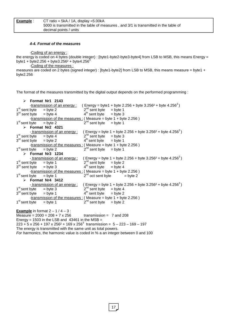
4-4. Format of the measures
-Coding of an energy :the energy is coded on 4 bytes (double integer) : [byte1-byte2-byte3-byte4] from LSB to MSB, this means Energy =byte1 + byte2.256 + byte3.256² + byte4.256
3
-Coding of the measures :measures are coded on 2 bytes (signed integer) : [byte1-byte2] from LSB to MSB, this means measure = byte1 +byte2.256
The format of the measures transmitted by the digital output depends on the performed programming :
Format Nr1 2143-transmission of an energy : ( Energy = byte1 + byte 2.256 + byte 3.256² + byte 4.256
3)
1st
sent byte = byte 2 2nd
sent byte = byte 13
rdsent byte = byte 4 4
thsent byte = byte 3
-transmission of the measures : ( Measure = byte 1 + byte 2.256 )1
stsent byte = byte 2 2
ndsent byte = byte 1
Format Nr2 4321- transmission of an energy : ( Energy = byte 1 + byte 2.256 + byte 3.256² + byte 4.256
3)
1st
sent byte = byte 4 2nd
sent byte = byte 33
rdsent byte = byte 2 4
thsent byte = byte 1
-transmission of the measures : ( Measure = byte 1 + byte 2.256 )1
stsent byte = byte 2 2
ndsent byte = byte 1
Format Nr3 1234- transmission of an energy : ( Energy = byte 1 + byte 2.256 + byte 3.256² + byte 4.256
3)
1st
sent byte = byte 1 2nd
sent byte = byte 23
rdsent byte = byte 3 4
thsent byte = byte 4
-transmission of the measures : ( Measure = byte 1 + byte 2.256 )1
stsent byte = byte 1 2
ndoct sent byte = byte 2
Format Nr4 3412- transmission of an energy : ( Energy = byte 1 + byte 2.256 + byte 3.256² + byte 4.256
3)
1st
sent byte = byte 3 2nd
sent byte = byte 43
rdsent byte = byte 1 4
thsent byte = byte 2
-transmission of the measures : ( Measure = byte 1 + byte 2.256 )1
stsent byte = byte 1 2
ndsent byte = byte 2
Example in format 2 – 1 / 4 – 3 :Measure = 2000 = 208 + 7 x 256 transmission = 7 and 208Energy = 1503 in the LSB and 43461 in the MSB =223 + 5 x 256 + 197 x 256² + 169 x 256
3transmission = 5 – 223 – 169 – 197
The energy is transmitted with the same unit as total powers.For harmonics, the harmonic value is coded in % a an integer between 0 and 100

18
Tables of decimal points / units : given for information if you do not want to read the 2nd
MODBUS table
3-phase network with neutral without neutral All networksVT primary UL-L CT primary IL10.0 – 99.9 V 2 / 0 1.00 – 9.99 A 3 / 0100 – 999 V 1 / 0 10.0 – 99.9 A 2 / 0
1.00 – 9.99 kV 3 / 1 100 – 999 A 1 / 010.0 – 99.9 kV 2 / 1 1.00 – 9.99 kA 3 / 1100 – 999 kV 1 / 1 10.0 – 99.9 kA 2 / 1
Example :For a 3-phase unbalanced 4 wire network (with neutral) 230Vac without external VT, CT 2500A / 5AProgramme as VT ratio : 230 / 230 as CT ratio : 2.50 kA / 5.0AThe VT primary is 230-which gives for the single voltage 1 / 0 (1 cipher after the decimal point in V)-for the mesh voltage 1 / 0 (1 cipher after the decimal point in V)The CT primary is 2.50 kA-which gives for the current 3 / 1 (3 ciphers after the decimal point in kA)
Calculation of the product of CT and VT primaries :3-phase network with neutral
3-phase network without neutral
Example :Let us take previous example again :The product VT primary x CT primary = 575 kW-which gives for powers per phase 1 / 0 (1 cipher after the decimal point in W)-for total powers and energies 3 / 1 (3 ciphers after the decimal point in kW)
VT primary UL-L UL-N10.0 – 57.7 V 2 / 0 2 / 057.8 – 99.9 V 1 / 0 2 / 0100 – 577 V 1 / 0 1 / 0578 – 999 V 3 / 1 1 / 0
1.00 – 5.77 kV 3 / 1 3 / 15.78 – 9.99 kV 2 / 1 3 / 110.0 – 57.7 kV 2 / 1 2 / 157.8 – 99.9 kV 1 / 1 2 / 1
Product VT primary x CT primary PL / QL P / Q / S / Ener10 W – 33.3 W 2 / 0 2 / 0
33.4 W – 99.9 W 2 / 0 1 / 0100 W – 333 W 1 / 0 1 / 0334 W – 999 W 1 / 0 3 / 1
1.00 kW – 3.33 kW 3 / 1 3 / 13.34 kW – 9.99 kW 3 / 1 2 / 110.0 kW – 33.3 kW 2 / 1 2 / 133.4 kW – 99.9 kW 2 / 1 1 / 1100 kW – 333 kW 1 / 1 1 / 1334 kW – 999 kW 1 / 1 3 / 2
1.00 MW – 3.33 MW 3 / 2 3 / 23.34 MW – 9.99 MW 3 / 2 2 / 210.0 MW – 33.3 MW 2 / 2 2 / 233.4 MW – 99.9 MW 2 / 2 1 / 2100 MW – 333 MW 1 / 2 1 / 2334 MW – 999 MW 1 / 2 3 / 3
Product VT priamry x CT primary P / Q / S / Ener10 W – 57.7 W 2 / 057.8 W – 577 W 1 / 0578 W – 5.77 kW 3 / 1
5.78 kW – 57.7 kW 2 / 157.8 kW – 577 kW 1 / 1578 kW – 5.77 MW 3 / 2
5.78 MW – 57.7 MW 2 / 257.8 MW – 577 MW 1 / 2

19
4-5. CRC16 calculation algorythm
Note 1 : = exclusive or Note 2 : poly = A001h Note 3 : the CRC16 calculation applies to
all bytes in the sequence (except CRC16) Note 4 : CAUTION in the CRC16, the first
byte sent is the least significant
Example :
Sequence 1 - 3 - 0 -75 - 0 - 2 - CRC16=180-29(in decimal)
FFFFh ->CRC
CRC BYTE ->CRC
N = 0
Shifts CRC by 1 bit to the right
carry
CRC poly ->CRC
N = N+1
N > 7
Next byte
End of sequence
END
no
yes
yes
yes
no
no
20
Version …
Language
Measures
Start
1 2 3 . 4
1 2 3 . 4
1 2 3 . 4
1 2 3 . 4
1 2 3 . 4
Yes
Save
PROGRAMMING BY THE µCONSOLE
1. ORGANISATION OF THE MENUS AND SPECIFIC ENTERINGS
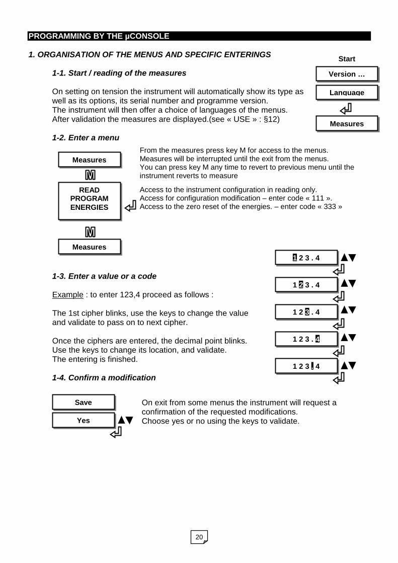
1-1. Start / reading of the measures
On setting on tension the instrument will automatically show its type aswell as its options, its serial number and programme version.The instrument will then offer a choice of languages of the menus.After validation the measures are displayed.(see « USE » : §12)
1-2. Enter a menu
1-3. Enter a value or a code
Example : to enter 123,4 proceed as follows :
The 1st cipher blinks, use the keys to change the valueand validate to pass on to next cipher.
Once the ciphers are entered, the decimal point blinks.Use the keys to change its location, and validate.The entering is finished.
1-4. Confirm a modification
READPROGRAMENERGIES
Measures
Access to the instrument configuration in reading only.Access for configuration modification – enter code « 111 ».Access to the zero reset of the energies. – enter code « 333 »
From the measures press key M for access to the menus.Measures will be interrupted until the exit from the menus.You can press key M any time to revert to previous menu until theinstrument reverts to measure
Measures
On exit from some menus the instrument will request aconfirmation of the requested modifications.Choose yes or no using the keys to validate.

21
2. ACCES TO THE MAIN MENU: Key menu allows access to the configurationThe instrument will show its features, and then open access to the main menu.
3. CHOICE OF THE LANGUAGEOn setting on tension, after the features, if the µconsole is connected, the instrument will offer achoice of language of the menus.
4. MODIFICATION OF THE CONFIGURATION – [ PROGRAM ]
4-1. Input parameters – [ INPUT ]
Validate to go on.
After choosing the menu PROGRAM, the instrument will request a codeCODE
Enter 111 to access the configuration in writing.111
Configuration of the measures (input parameters)INPUT
Configuration of the RS422/485 – Only if the option is presentMODBUS
Configuration of the outputs – According to the present optional outputs.OUTPUT
Validate the choice to go on.
Validate to go on.
Choice among 3 types of networks: 1 PHAS : single phaseNETWORK
3W BAL 3 phase bal. without neutral – 4W BAL 3 phase balanced with neutral1 PHAS
Choice of the network type
Choose the language of the menus : FRANÇAIS / ENGLISH. Validate the choice.FRANCAIS
Access to the instrument configuration in reading onlyREAD
Modification of the instrument configurationPROGRAM
Zero reset of the energy countersENERGY
Then validate (key enter).

22
Validate to go on.
Choice of the voltage caliberRANGE U
Choose between 500V / 150V500V
Validate to go on.
Choice of the current caliberRANGE I
Choose between 5A / 1A5A
Entering of the CT primaryPRIMARY CT
Enter the value and the decimal point location.5.00
Choice of the unit : x1 / KILO / MEGA / GIGAx1
Validate the choice to go on.
Validate to go on.
Entering of the CT secondarySECONDARY
Enter the value and the decimal point location.05.0
Entering of the VT primaryPRIMARY VT
Enter the value and the decimal point location.5.00
Choice of the unit : x1 / KILO / MEGA / GIGAx1
Validate the choice to go on.
Validate to go on.
Entering of the VT secondarySECONDARY
Enter the value and the decimal point location.05.0
Validate to go on.
Choice of the weight of the digital filtering applied to the measuresFILTERING
Choose the value : OFF / Nr1 / Nr2.Nr.1
Validate to go on.
Choose the direction of the currentDIRECTION I
REC : Receiving / GEN Generating.REC

23
4-2. Parameters of the RS output – [ MODBUS ]
If option RS N is not present the parameters are : Slave = 250, Speed = 9600. Only the
instrument configuration can be accessed via the modbus, no measure can be transmitted.
Validate to go on.
Choice of the cosine type (see. PROGRAMMING BY PC SOFTWARE - 3.21)COS TYPE
MATH : Mathematical / ELEC : Electrical.ELEC
Validate to go on.
Choice of the cosine centering (see. PROG. BY PC SOFTWARE - 3.21)COS OUTPUT
COS +/-1 : Centered on +/-1 / COS 0 : centered on 0. (Incidence on the ana. output)+/-1
Validate to go on.
Entering of the currents cut off in %CUT-OFF I(%)
Enter the value. The decimal point location is fixed.05.0
Validate to revert to menu [PROGRAM]
Entering of the voltages cut off in %CUT-OFF U(%)
Enter the value. The decimal point location is fixed.05.0
Validate to go on
Choice of the Modbus slave numberSLAVE
Choice from 1 to 250.250
Validate to go on
Choice of the communication speedSPEED
Choice among 4800 bd / 9600 bd / 19.2 kbd.9600 bd
Validate to go on
Choose the number of stop bitsSTOP BIT
1 or 2 stop bits.1 BIT
Validate to go on
Choice of the parityPARITY
On choice : without parity, even or oddNO

24
4-3. Parameters of the optional outputs – [ OUTPUT ]
4-31. Output 1 – Analog
Validate to go on.
Choice of the output Choice : Analog / Relay1 / Relay2ANALOG
Validate to go on.
Parameter assigned to the outputPARAMETER
Choice of the parameter number. (see PROG BY PC SOFTWARE – chap. 4-3).4 IL1
Validate to go on.
Output scaleRANGE I
Choice –20/20mA -10/10mA –5/5mA 4/20mA 0/20mA 0/10mA 0/5mA4 20mA
Entering of the input down scaleLO RANGE
Enter the value and the decimal point location.0.000
Choice of the unit : x1 / KILO / MEGA / GIGAx1
Validate the choice to go on.
Validate to go on
Choice of the 1st parameter transmitted by modbusPARAMETER
Choice of the parameter number. (see PROG BY PC SOFTWARE – chapter 4-3).1 U13
…
Validate to revert to menu [PROGRAM]
Choice of the 12th (and last) parameter transmitted by modbusPARAMETER
Choice of the parameter number. (cf. PROG BY PC SOFTWARE– chapter 4-3).4 IL1
Validate to go on
Transmission format of the measuresFORMAT
Choose the rank of the transmitted bytes : 2-1/4-3 or 4-3/2-1 or 1-2/3-4 or 3-4/1-22-1 4-3
25
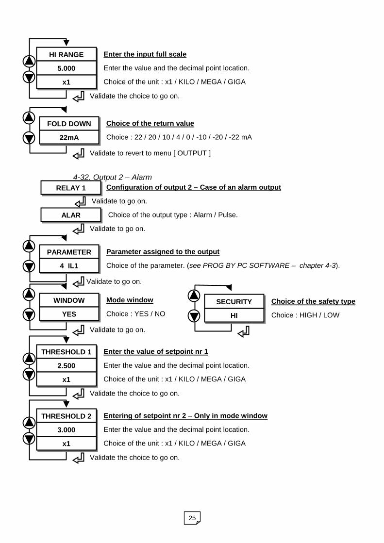
4-32. Output 2 – Alarm
Enter the input full scaleHI RANGE
Enter the value and the decimal point location.5.000
Choice of the unit : x1 / KILO / MEGA / GIGAx1
Validate the choice to go on.
Validate to revert to menu [ OUTPUT ]
Choice of the return valueFOLD DOWN
Choice : 22 / 20 / 10 / 4 / 0 / -10 / -20 / -22 mA22mA
Validate to go on.
Parameter assigned to the outputPARAMETER
Choice of the parameter. (see PROG BY PC SOFTWARE – chapter 4-3).4 IL1
Configuration of output 2 – Case of an alarm output
Validate to go on.
RELAY 1
Choice of the output type : Alarm / Pulse.
Validate to go on.
ALAR
Validate to go on.
Mode windowWINDOW
Choice : YES / NOYES
Enter the value of setpoint nr 1THRESHOLD 1
Enter the value and the decimal point location.2.500
Choice of the unit : x1 / KILO / MEGA / GIGAx1
Validate the choice to go on.
Entering of setpoint nr 2 – Only in mode windowTHRESHOLD 2
Enter the value and the decimal point location.3.000
Choice of the unit : x1 / KILO / MEGA / GIGAx1
Validate the choice to go on.
Choice of the safety typeSECURITY
Choice : HIGH / LOWHI
26
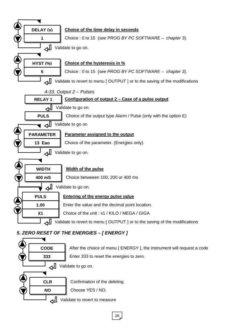
4-33. Output 2 – Pulses
5. ZERO RESET OF THE ENERGIES – [ ENERGY ]
Validate to go on.
After the choice of menu [ ENERGY ], the instrument will request a codeCODE
Enter 333 to reset the energies to zero.333
Validate to revert to measure
Confirmation of the deletingCLR
Choose YES / NO.NO
Validate to go on.
Choice of the time delay in secondsDELAY (s)
Choice : 0 to 15 (see PROG BY PC SOFTWARE – chapter 3).1
Validate to revert to menu [ OUTPUT ] or to the saving of the modifications
Choice of the hysteresis in %HYST (%)
Choice : 0 to 15 (see PROG BY PC SOFTWARE – chapter 3).5
Entering of the energy pulse valuePULS
Enter the value and the decimal point location.1.00
Choice of the unit : x1 / KILO / MEGA / GIGAX1
Validate to revert to menu [ OUTPUT ] or to the saving of the modifications
Validate to go on.
Parameter assigned to the outputPARAMETER
Choice of the parameter. (Energies only).13 Eao
Configuration of output 2 – Case of a pulse output
Validate to go on.
RELAY 1
Choice of the output type Alarm / Pulse (only with the option E)
Validate to go on
PULS
Validate to go on.
Width of the pulseWIDTH
Choice betweeen 100, 200 or 400 ms400 mS

27
TECHNICAL FEATURES
1. GENERAL FEATURES
Case Self-extinguishing black ABS .UL94VO.Format (H x L x D) 75 x 22.5 x 120 mmMounting Latching on DIN railProtection Case IP30 (with terminals).Connectings By removable screwed connectors (wire section 2.5 mm2).Indicators 3 LED.Programming Micro-console or PC programme
2. ELECTRICAL FEATURESPOWER SUPPLY
Voltage Version High Voltage or Low Voltage (specify on order)2 : 90 to 270 VAC or 88 to 350VDC
3 : 20 to 40 VAC or 20 to 60VDC
Power draw 5 VA max.INPUTS
Voltages 2 programmable calibers Un=150VAC and 500VAC. Oversteppings120% Un
Currents 2 programmable calibers 1A et 5A : In=1,2A et 6A. Oversteppings120% In
Overloads Permanent : 750V, 10ADuring 10 s : 1000V, 50A
Power draws Voltage inputs : resistance 1M Current inputs : < 0.2VATest voltage 2KV, 50Hz /1min.Frequency 45 … 50 … 65Hz (as standard)Network type Single or 3-phase balanced with or without neutral.Thermic drifts <200ppm
MEASURES
Number of parameters 12 measurable parametersAccuracy rating In digital output Cl. 0.2 voltage/current, cl. 0.5 powers (IEC60688-1).Measure cycle 55 ms for all types of networksMeasuring method Fast simultaneous sampling of voltages and currents.
Digital calculation (32 bits). Measurement of disturbed signals pass-band 800Hz.
Harmonics analysis Harmonics analysis up to rank 50 on the 6 channels.Digital filtering Various levels on choice by programming.Energies Saved every 5 min. Active energy accuracy :
caliber 5A = class 1 / caliber 1A = class 2 - (IEC62053-21)TEST AND OPERATING CONDITIONS
Reference T° 23°COperating T° 0°C to 55°C (others on request) IEC 60068-2-1 and IEC 60068-2-2… in damp area 40°C to 93% condense-free dampness IEC 60068-2-30Storage T° -25°C to 70°C IEC 60068-2-1 and IEC 60068-2-2T° gradiant in storage 3°C/min from –20°C to +70°C IEC 60068-2-14Relative dampness 5% to 95% without condensation IEC 60068-2-30Rayed field HF IEC 61000.4.3 level 3Electrostatic disch. IEC 61000.4.2 level 3Conducted field RF IEC 61000.4.6 level 3Magnetic field 50Hz IEC 61000.4.8 level 3

28
Shockwaves 1.2/50s IEC 61000.4.5 level 3 mode series/commonFast transient IEC 61000.4.4 level 3 mode commonRF GSM field ENV 50204Generic standards Immunity : IEC 61000-6-2 emissions : 61000-6-4Vibrationwithstanding
+/-150µm from 10 to 57 Hz and +/- 2G from 57Hz to 500Hz according toIEC 60068-2-6CE Marking
29
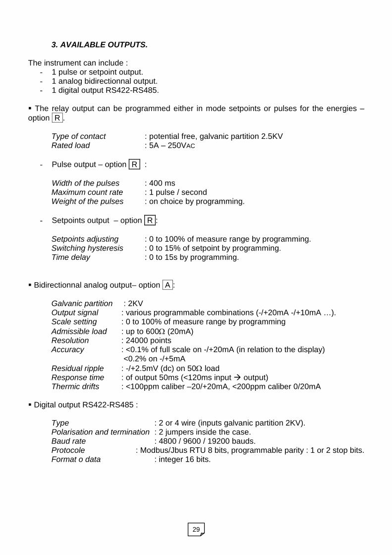
3. AVAILABLE OUTPUTS.
The instrument can include :- 1 pulse or setpoint output.- 1 analog bidirectionnal output.- 1 digital output RS422-RS485.
The relay output can be programmed either in mode setpoints or pulses for the energies –option R .
Type of contact : potential free, galvanic partition 2.5KVRated load : 5A – 250VAC
- Pulse output – option R :
Width of the pulses : 400 msMaximum count rate : 1 pulse / secondWeight of the pulses : on choice by programming.
- Setpoints output – option R :
Setpoints adjusting : 0 to 100% of measure range by programming.Switching hysteresis : 0 to 15% of setpoint by programming.Time delay : 0 to 15s by programming.
Bidirectionnal analog output– option A :
Galvanic partition : 2KVOutput signal : various programmable combinations (-/+20mA -/+10mA …).Scale setting : 0 to 100% of measure range by programmingAdmissible load : up to 600 (20mA)Resolution : 24000 pointsAccuracy : <0.1% of full scale on -/+20mA (in relation to the display)
<0.2% on -/+5mAResidual ripple : -/+2.5mV (dc) on 50 loadResponse time : of output 50ms (<120ms input output)Thermic drifts : <100ppm caliber –20/+20mA, <200ppm caliber 0/20mA
Digital output RS422-RS485 :
Type : 2 or 4 wire (inputs galvanic partition 2KV).Polarisation and termination : 2 jumpers inside the case.Baud rate : 4800 / 9600 / 19200 bauds.Protocole : Modbus/Jbus RTU 8 bits, programmable parity : 1 or 2 stop bits.Format o data : integer 16 bits.
30
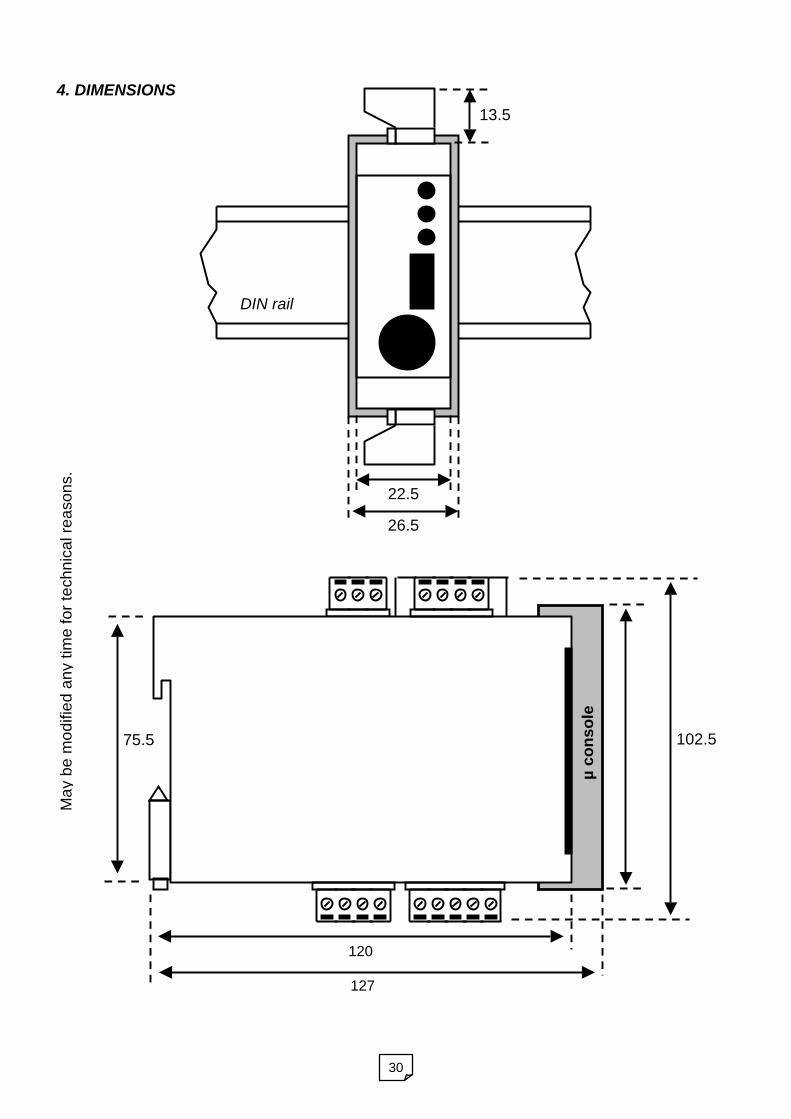
4. DIMENSIONS
Ma
yb
em
od
ifie
da
ny
tim
efo
rte
ch
nic
alre
aso
ns.
75.5
120
127
µc
on
so
le
102.5
DIN rail
22.5
13.5
26.5
31
WIRING
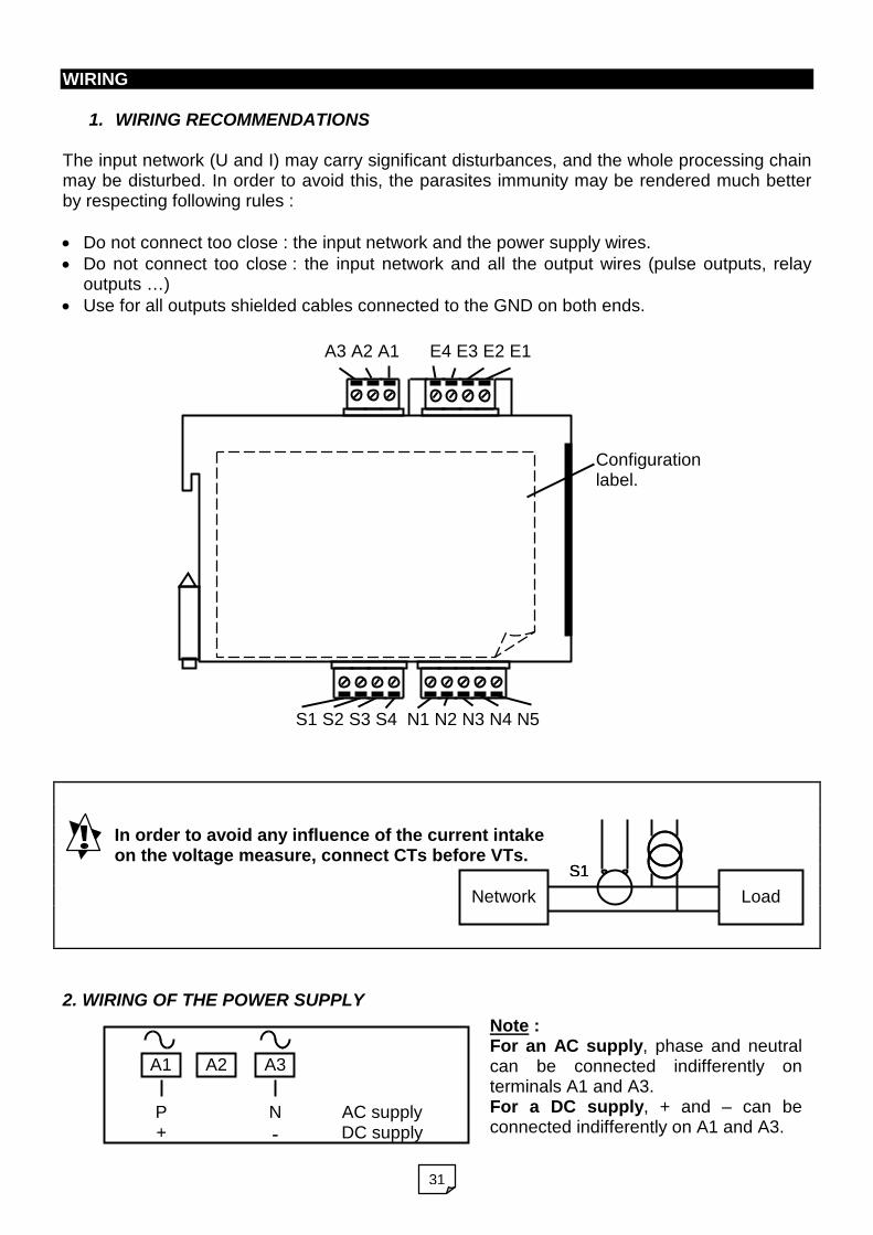
1. WIRING RECOMMENDATIONS
The input network (U and I) may carry significant disturbances, and the whole processing chainmay be disturbed. In order to avoid this, the parasites immunity may be rendered much betterby respecting following rules :
Do not connect too close : the input network and the power supply wires. Do not connect too close : the input network and all the output wires (pulse outputs, relay
outputs …) Use for all outputs shielded cables connected to the GND on both ends.
In order to avoid any influence of the current intakeon the voltage measure, connect CTs before VTs.
2. WIRING OF THE POWER SUPPLY
A3 A2 A1 E4 E3 E2 E1
S1 S2 S3 S4 N1 N2 N3 N4 N5
Configurationlabel.
Note :For an AC supply, phase and neutralcan be connected indifferently onterminals A1 and A3.For a DC supply, + and – can beconnected indifferently on A1 and A3.
A1 A3A2
P+
N
-AC supplyDC supply
LoadNetwork
S1S1
32
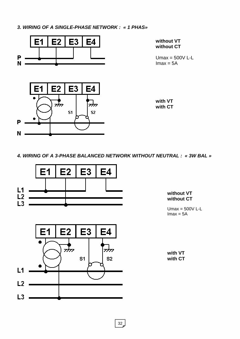
3. WIRING OF A SINGLE-PHASE NETWORK : « 1 PHAS»
4. WIRING OF A 3-PHASE BALANCED NETWORK WITHOUT NEUTRAL : « 3W BAL »
without VTwithout CT
Umax = 500V L-LImax = 5A
with VTwith CT
without VTwithout CT
Umax = 500V L-LImax = 5A
with VTwith CT

33
5. WIRING OF A 3-PHASE BALANCED NETWORK WITH NEUTRAL : « 4W BAL »
6. WIRING OF THE RELAY & ANALOG OUTPUT
without VTwithout CT
Umax = 500V L-NImax = 5A
With VTWith CT
Respect connectings :S1 corresponds to P1 and S2 corresponds to P2.S2 secondaries of CTs and VTs must be connected to the earth.
I
Lr< 600 (20 mA)
+ -
S2S1 S4S3
Potential free contact 5A/250V

34
7. WIRING OF THE DIGITAL OUTPUT RS485- The end of line resistor Zo on the master reduces the influence of reflections on the lines.
For speeds <9600 bauds the resistor is not necessary, from 1000m at 9600 bd and 700mat 19200 bd it is compulsory.
- The use of shielded cables is preferable to reduce the environment influence. Connectthe earth to both ends of the cable shielding, and the GND to one of the ends.
- In case of communication problem : invert Rx and Tx polarities on the master. Check thatthe master’s emission arrives on the Tx wire.
- Switch termination and polarisation resistance Zo on the end of line instrument (120 Ohm).7-1. Wiring RS485 / 422 4 wire
7-2. Wiring RS485 2 wire
7-3. Terminations
CAUTION : The master must always polarise the lines. Switch the end of line andpolarisation resistors et the level of the master. If necessary place the Zo resistor on the endof line instrument (see above).
Notes : In 4 wire, the master’s emission driver must always be enabled. This is performed
either with the software if it has a selection 2/4 wire, or in the interface 485/422using a micro-switch.
In 2 wire, the master’s emission driver must be validated only if it is sending . This isperformed either with the software if it has a selection 4/2 wire, or in the interfaceRS485 using a micro-switch which validates the emission driver with the signal RTS(or DTR).
GND Rx- Rx+ Tx- Tx+
RS485 / interface
Zo
GND Rx- Rx+ Tx- Tx+
Instrument n°1
N1 N2 N3 N4 N5
PC / PLC
Transmission lineEarth (EMC GND)
GND Rx- Rx+ Tx- Tx+
RS485 / interface
Zo
GND Rx- Rx+ Tx- Tx+
Instrument n°1
N1 N2 N3 N4 N5
PC / PLC
Transmission lineEarth (EMC GND)
35
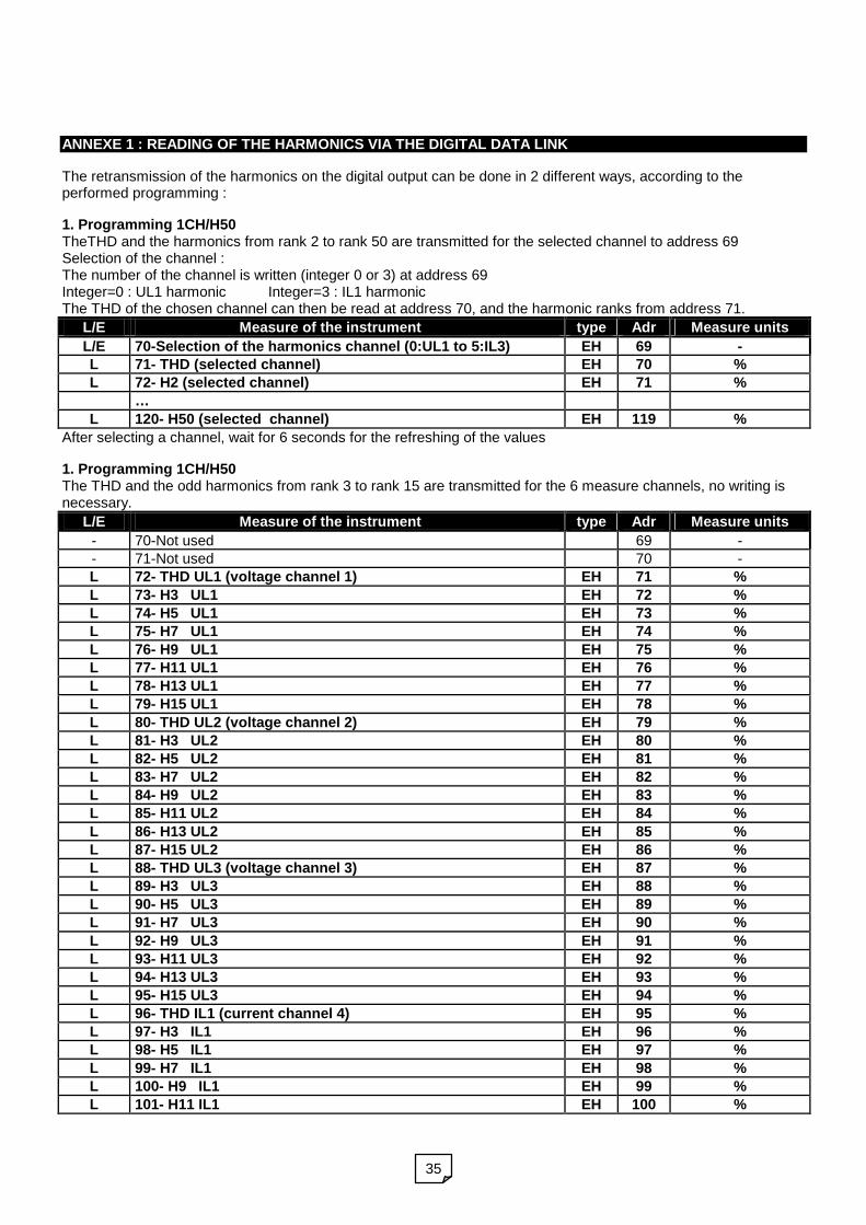
ANNEXE 1 : READING OF THE HARMONICS VIA THE DIGITAL DATA LINK
The retransmission of the harmonics on the digital output can be done in 2 different ways, according to theperformed programming :
1. Programming 1CH/H50TheTHD and the harmonics from rank 2 to rank 50 are transmitted for the selected channel to address 69Selection of the channel :The number of the channel is written (integer 0 or 3) at address 69Integer=0 : UL1 harmonic Integer=3 : IL1 harmonicThe THD of the chosen channel can then be read at address 70, and the harmonic ranks from address 71.
L/E Measure of the instrument type Adr Measure units
L/E 70-Selection of the harmonics channel (0:UL1 to 5:IL3) EH 69 -L 71- THD (selected channel) EH 70 %
L 72- H2 (selected channel) EH 71 %
…
L 120- H50 (selected channel) EH 119 %
After selecting a channel, wait for 6 seconds for the refreshing of the values
1. Programming 1CH/H50The THD and the odd harmonics from rank 3 to rank 15 are transmitted for the 6 measure channels, no writing isnecessary.
L/E Measure of the instrument type Adr Measure units
- 70-Not used 69 -- 71-Not used 70 -L 72- THD UL1 (voltage channel 1) EH 71 %
L 73- H3 UL1 EH 72 %
L 74- H5 UL1 EH 73 %
L 75- H7 UL1 EH 74 %
L 76- H9 UL1 EH 75 %
L 77- H11 UL1 EH 76 %
L 78- H13 UL1 EH 77 %
L 79- H15 UL1 EH 78 %
L 80- THD UL2 (voltage channel 2) EH 79 %
L 81- H3 UL2 EH 80 %
L 82- H5 UL2 EH 81 %
L 83- H7 UL2 EH 82 %
L 84- H9 UL2 EH 83 %
L 85- H11 UL2 EH 84 %
L 86- H13 UL2 EH 85 %
L 87- H15 UL2 EH 86 %
L 88- THD UL3 (voltage channel 3) EH 87 %
L 89- H3 UL3 EH 88 %
L 90- H5 UL3 EH 89 %
L 91- H7 UL3 EH 90 %
L 92- H9 UL3 EH 91 %
L 93- H11 UL3 EH 92 %
L 94- H13 UL3 EH 93 %
L 95- H15 UL3 EH 94 %
L 96- THD IL1 (current channel 4) EH 95 %
L 97- H3 IL1 EH 96 %
L 98- H5 IL1 EH 97 %
L 99- H7 IL1 EH 98 %
L 100- H9 IL1 EH 99 %
L 101- H11 IL1 EH 100 %

36
L 102- H13 IL1 EH 101 %
L 103- H15 IL1 EH 102 %
L 104- THD IL2 (current channel 5) EH 103 %
L 105- H3 IL2 EH 104 %
L 106- H5 IL2 EH 105 %
L 107- H7 IL2 EH 106 %
L 108- H9 IL2 EH 107 %
L 109- H11 IL2 EH 108 %
L 110- H13 IL2 EH 109 %
L 111- H15 IL2 EH 110 %
L 112- THD IL3 (current channel 6) EH 111 %
L 113- H3 IL3 EH 112 %
L 114- H5 IL3 EH 113 %
L 115- H7 IL3 EH 114 %
L 116- H9 IL3 EH 115 %
L 117- H11 IL3 EH 116 %
L 118- H13 IL3 EH 117 %
L 119- H15 IL3 EH 118 %
120-Not used 119 -
Related Documents