THESE INSTRUCTIONS APPLY TO THE FOLLOWING MODEL: TRIPOD USER INSTRUCTION MANUAL UFT510010

Welcome message from author
This document is posted to help you gain knowledge. Please leave a comment to let me know what you think about it! Share it to your friends and learn new things together.
Transcript
THESE INSTRUCTIONS APPLY TO THE FOLLOWING MODEL:
TRIPODUSER INSTRUCTION MANUAL
UFT510010
Do not skip this instruction manual. Read the instruction manual carefully before using the equipment. If failed in doing so it may cause serious Injury or Death.
Note: The user is advised to keep the user instructions document for the life of the product.
This manual must be read and understood in its entirety and used as part of fall protection training program as required by OSHA or
any state regularity agency. These instructions are intended to meet the manufacturer instructions as required by ANSI Z 359.18-
2017 and OSHA . The user must fully understand the proper equipment use and limitations.
KStrong Anchors should be used only with the combinations of components, sub-systems or both which may affect or interfere with the safe function of one another. Be certain that connecting devices are compatible and that other elements of the PFAS are safe and compatible before use.
SYSTEM LIMITATIONS and REQUIREMENTS: Consider the following limitations/requirements prior to installing or using this equipment:
Capacity: KStrong Tripod is designed for use by ONE person with a combined weight (clothing, tools, etc.) of no more than 310 lbs. Make sure all of the components in your system are rated to a capacity appropriate to your application. KStrong Tripod is rated 5000lbs.
Ÿ Free Fall: Personal fall arrest systems used with this equipment must be rigged to limit the free fall to 6 feet per ANSI Z359.1.
IMPORTANT INFORMATION:Ÿ It is important to inspect the equipment according to the manufacturer's instructions before each use.Ÿ Inspection of equipment should be done on a regular basis by a qualified person and the results should be recorded in
the inspection log.Ÿ DO NOT REMOVE product labels which include important warnings and information for the “Authorized person”. Ÿ "Authorized Person" is a person who is exposed to fall hazards during the course of their work. This individual requires
formal training in the use of personal fall protection equipment and systems. The term "Authorized Person" may be used interchangeably with "User" and "End-User".
Ÿ DO NOT ALTER the equipment in any way. Ÿ Always send the equipment back to the manufacturer, or to the persons or entities authorized in writing by the
manufacturer, for any repairs if required. Ÿ Never use any natural material like manila, cotton, etc. as part of the Fall Protection System.Ÿ Fall protection equipment should only be used for the purpose for which it has been designed.Ÿ This equipment should never be used for towing and hoisting or for any other purpose than its intended use.Ÿ A competent person must ensure compatibility of the system to minimize any potential for accidental disengagement. Ÿ Authorized persons or users shall be trained on all warnings and instructions provided in this manual.Ÿ It is important for all authorized persons and users to refer to the applicable ANSI Standards and to the regulations
governing occupational safety.Ÿ Take proper precautions to remove any debris, material, obstructions, etc., from the work area which could cause
injury, or otherwise interfere with the functioning of the system.Ÿ
Ÿ Always check for obstructions below the work area to make sure that the potential fall path is clear.Ÿ Keep the equipment away from anything that could damage it such as sharp edges, rough or abrasive surfaces, high
temperature surfaces, heat and welding sources, moving machinery, electrical hazards, etc.Ÿ It is important to keep in mind environmental hazards when selecting fall protection equipment.Ÿ Do not expose the equipment to chemicals, highly corrosive or caustic environments, or to direct sunlight and UV
radiation, which may cause UV degradation. Ÿ Such harmful environments require a more frequent inspection and servicing program of the fall protection equipment
to maintain the integrity and safety of the equipment. Contact KStrong if in doubt.Ÿ All the synthetic material of fall protection equipment must be protected from slag, hot sparks, open flames or other
heat sources.Ÿ It is recommended that heat resistant materials are used in such applications. It is important to allow adequate fall
clearance below the work surface.Ÿ Always have a Rescue Plan ready and at hand when using this equipment.
WARNING !!
Ÿ Immediately discard any product which is exhibiting unusual wear, deformity or deterioration.Ÿ Immediately remove from service any equipment that has been subjected to a fall.
Ÿ
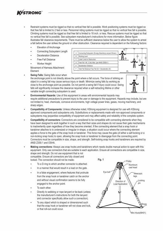
Ÿ Restraint systems must be rigged so that no vertical free fall is possible. Work positioning systems must be rigged so that free fall is limited to 2 feet or less. Personnel riding systems must be rigged so that no vertical free fall is possible. Climbing systems must be rigged so that free fall is limited to 18 inch. or less. Rescue systems must be rigged so that no vertical free fall is possible. See subsystem manufacturer's instructions for more information. Below figure illustrates fall clearance requirements. There must be sufficient clearance below the user to allow the system to arrest a fall before the user strikes the ground or other obstruction. Clearance required is dependent on the following factors:
Elevation of Anchorage
Connecting Subsystem Length
Deceleration Distance
Free Fall Distance
Worker Height
Movement of Harness Attachment Element
Swing Falls: Swing falls occur when the anchorage point is not directly above the point where a fall occurs. The force of striking an object in a swing fall may cause serious injury or death. Minimize swing falls by working as close to the anchorage point as possible. Do not permit a swing fall if injury could occur. Swing falls will significantly increase the clearance required when a self-retracting lifeline or other variable length connecting subsystem is used.
Environmental Hazards: Use of this equipment in areas with environmental hazards may require additional precautions to prevent injury to the user or damage to the equipment. Hazards may include, but are not limited to; heat, chemicals, corrosive environments, high voltage power lines, gases, moving machinery, and sharp edges.
Compatibility of Components: Unless otherwise noted, KStrong equipment is designed for use with KStrong approved components and subsystems only. Substitutions or replacements made with non-approved components or subsystems may jeopardize compatibility of equipment and may affect safety and reliability of the complete system.
Compatibility of connectors: Connectors are considered to be compatible with connecting elements when they have been designed to work together in such a way that their sizes and shapes do not cause their gate mechanisms to inadvertently open regardless of how they become oriented. If the connecting element that a snap hook or karabiner attaches to is undersized or irregular in shape, a situation could occur where the connecting element applies a force to the gate of the snap hook or karabiner. This force may cause the gate (of either a self-locking or a non-locking snap hook) to open, allowing the snap hook or karabiner to disengage from the connecting point. Connectors must be compatible in size, shape, and strength. Self-locking snap hooks and karabiners are required by ANSI Z359.1 and OSHA.
Making connections: Always use snap hooks and karabiners which needs double manual action to open with this equipment. Only use connectors that are suitable to each application. Ensure all connections are compatible in size, shape and strength. Do not use equipment that is not compatible. Ensure all connectors are fully closed and locked. The connection should not be made-
To a D-ring to which another connector is attached.
In a manner that would result in a load on the gate.
In a false engagement, where features that protrude
from the snap hook or karabiner catch on the anchor
and without visual confirmation seems to be fully
engaged to the anchor point.
To each other.
Directly to webbing or rope lanyard or tie-back (unless the manufacturer's instructions for both the lanyard and connector specifically allow such a connection).
To any object which is shaped or dimensioned such that the snap hook or karabiner will not close and lock, or that roll-out could occur.
Ÿ
Ÿ
Ÿ
Ÿ
Ÿ
Ÿ
Ÿ
Ÿ
Ÿ
Ÿ
Ÿ
Ÿ
Ÿ
Ÿ
Ÿ
Ÿ
D
F
E
C
B
A
Fig. 1
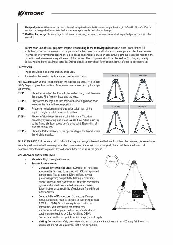
Mini Hook(MH01)
Aluminumcast head
Pulley
Telescopiclegs
Lockingpin
Shoes
Eye bolt
Direction ofLoad Application
A Connecting Subsystem (Energy Absorbing Lanyard Shown)
B Working Level
C Lower Level or Obstruction
D Free Fall - 6ft. (1.8m) Max. (per ANSI Z3559.1)
E Deceleration Distance
F Total Fall Distance Free Fall (D) + Deceleration (E)
NOTE: Other than 3,600 lbs. gated hooks, large throat opening snap hooks should not be connected to standard size D-rings or similar objects which will result in a load on the gate if the hook or D-ring twists or rotates. Large throat snap hooks are designed for use on fixed structural elements such as rebar or cross members that are not shaped in a way that can capture the gate of the hook.
RESTRICTIONS REGARDING MAKING CONNECTIONS:
Ÿ Use connectors conforming to ANSI standards to make connections.
Do not make connections where the hook locking mechanism can come into contact with a structural member or other equipment and potentially release the hook.
Do not connect a snap hook into a loop or thimble of a wire rope or attach in any way to a slack wire rope.
The snap hook must be free to align with the applied load as intended (regardless of the size or shape of the mating connector)
A karabiner may be used to connect to a single or pair of soft loops on a body support such as a body belt or full body harness, provided the karabiner can fully close and lock. This type of connection is not allowed for snap hooks.
A karabiner may be connected to a loop or ring connector that is already occupied by an automatic closing connector.
Ÿ
Ÿ
Ÿ
Ÿ
Ÿ
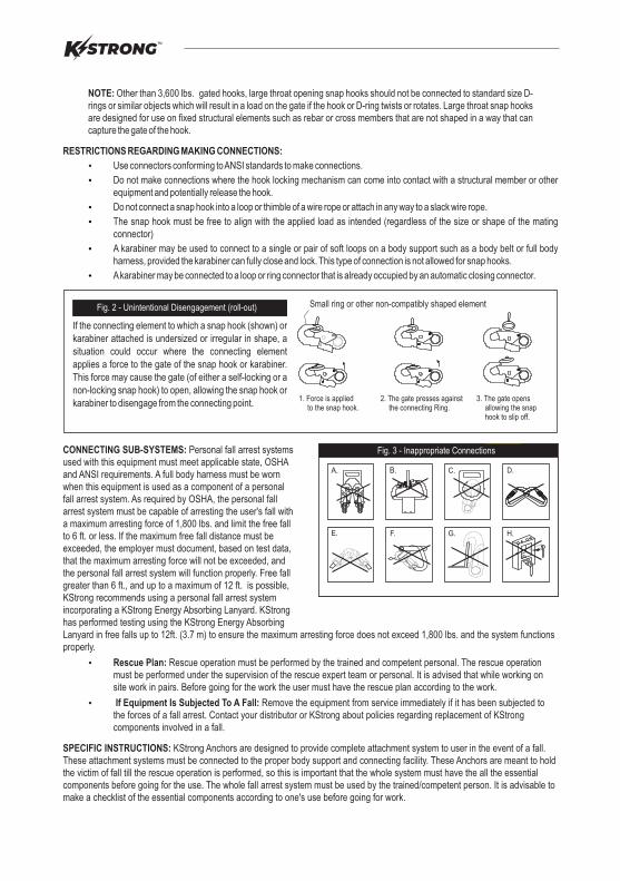
C.B.A.
F.E.
D.
G.
Fig. 3 - Inappropriate Connections
H.
If the connecting element to which a snap hook (shown) or karabiner attached is undersized or irregular in shape, a situation could occur where the connecting element applies a force to the gate of the snap hook or karabiner. This force may cause the gate (of either a self-locking or a non-locking snap hook) to open, allowing the snap hook or karabiner to disengage from the connecting point.
Small ring or other non-compatibly shaped element
1. Force is applied to the snap hook.
2. The gate presses against the connecting Ring.
3. The gate opens allowing the snap hook to slip off.
Fig. 2 - Unintentional Disengagement (roll-out)
CONNECTING SUB-SYSTEMS: Personal fall arrest systems used with this equipment must meet applicable state, OSHA and ANSI requirements. A full body harness must be worn when this equipment is used as a component of a personal fall arrest system. As required by OSHA, the personal fall arrest system must be capable of arresting the user's fall with a maximum arresting force of 1,800 lbs. and limit the free fall to 6 ft. or less. If the maximum free fall distance must be exceeded, the employer must document, based on test data, that the maximum arresting force will not be exceeded, and the personal fall arrest system will function properly. Free fall greater than 6 ft., and up to a maximum of 12 ft. is possible, KStrong recommends using a personal fall arrest system incorporating a KStrong Energy Absorbing Lanyard. KStrong has performed testing using the KStrong Energy Absorbing Lanyard in free falls up to 12ft. (3.7 m) to ensure the maximum arresting force does not exceed 1,800 lbs. and the system functions properly.
Ÿ Rescue Plan: Rescue operation must be performed by the trained and competent personal. The rescue operation must be performed under the supervision of the rescue expert team or personal. It is advised that while working on site work in pairs. Before going for the work the user must have the rescue plan according to the work.
Ÿ If Equipment Is Subjected To A Fall: Remove the equipment from service immediately if it has been subjected to the forces of a fall arrest. Contact your distributor or KStrong about policies regarding replacement of KStrong components involved in a fall.
SPECIFIC INSTRUCTIONS: KStrong Anchors are designed to provide complete attachment system to user in the event of a fall. These attachment systems must be connected to the proper body support and connecting facility. These Anchors are meant to hold the victim of fall till the rescue operation is performed, so this is important that the whole system must have the all the essential components before going for the use. The whole fall arrest system must be used by the trained/competent person. It is advisable to make a checklist of the essential components according to one's use before going for work.
USE OF FALL ARREST SYSTEM: The fall arrest system MUST ONLY be connected to the back attaching element on the harness provided for the purpose (”D” ring or webbing attachment extension) or to the chest anchorage points (“webbing link” or “D” link). The chest anchorage points must imperatively be used together. The D-rings on the belt and the ventral anchorage point must only be used for the attachment of a work positioning or retaining system and never with a fall arrest system.During use, check regularly the adjustment and/or attachment points.
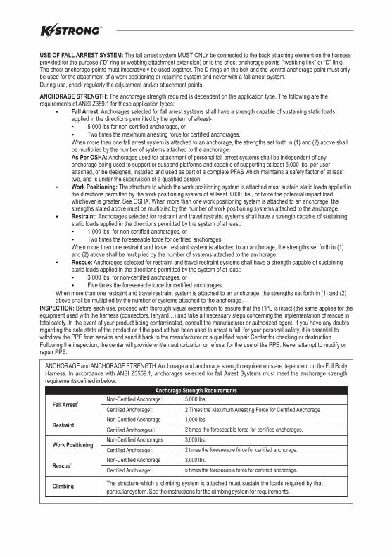
ANCHORAGE STRENGTH: The anchorage strength required is dependent on the application type. The following are the requirements of ANSI Z359.1 for these application types:
Ÿ
Ÿ
Ÿ
Ÿ
Fall Arrest: Anchorages selected for fall arrest systems shall have a strength capable of sustaining static loads applied in the directions permitted by the system of atleast-
5,000 lbs for non-certified anchorages, or Two times the maximum arresting force for certified anchorages.
When more than one fall arrest system is attached to an anchorage, the strengths set forth in (1) and (2) above shall be multiplied by the number of systems attached to the anchorage. As Per OSHA: Anchorages used for attachment of personal fall arrest systems shall be independent of any anchorage being used to support or suspend platforms and capable of supporting at least 5,000 lbs. per user attached, or be designed, installed and used as part of a complete PFAS which maintains a safety factor of at least two, and is under the supervision of a qualified person.
Work Positioning: The structure to which the work positioning system is attached must sustain static loads applied in the directions permitted by the work positioning system of at least 3,000 lbs., or twice the potential impact load, whichever is greater. See OSHA. When more than one work positioning system is attached to an anchorage, the strengths stated above must be multiplied by the number of work positioning systems attached to the anchorage.
Restraint: Anchorages selected for restraint and travel restraint systems shall have a strength capable of sustaining static loads applied in the directions permitted by the system of at least:
1,000 lbs. for non-certified anchorages, or Two times the foreseeable force for certified anchorages.
When more than one restraint and travel restraint system is attached to an anchorage, the strengths set forth in (1) and (2) above shall be multiplied by the number of systems attached to the anchorage.
Rescue: Anchorages selected for restraint and travel restraint systems shall have a strength capable of sustaining static loads applied in the directions permitted by the system of at least:
3,000 lbs. for non-certified anchorages, or Five times the foreseeable force for certified anchorages.
When more than one restraint and travel restraint system is attached to an anchorage, the strengths set forth in (1) and (2) above shall be multiplied by the number of systems attached to the anchorage.
INSPECTION: Before each use, proceed with thorough visual examination to ensure that the PPE is intact (the same applies for the equipment used with the harness (connectors, lanyard…) and take all necessary steps concerning the implementation of rescue in total
Ÿ
Ÿ
Ÿ
Ÿ
Ÿ
Ÿ
safety. In the event of your product being contaminated, consult the manufacturer or authorized agent. If you have any doubts regarding the safe state of the product or if the product has been used to arrest a fall, for your personal safety, it is essential to withdraw the PPE from service and send it back to the manufacturer or a qualified repair Center for checking or destruction. Following the inspection, the center will provide written authorization or refusal for the use of the PPE. Never attempt to modify or repair PPE.
ANCHORAGE and ANCHORAGE STRENGTH: Anchorage and anchorage strength requirements are dependent on the Full Body Harness. In accordance with ANSI Z3559.1, anchorages selected for fall Arrest Systems must meet the anchorage strength requirements defined in below:
Anchorage Strength Requirements
1Fall Arrest
1Restraint
1Work Positioning
1Rescue
Climbing
Non-Certified Anchorage
2Certified Anchorage :
Non-Certified Anchorage:
2Certified Anchorage :
Non-Certified Anchorage
2Certified Anchorages :
Non-Certified Anchorages
2Certified Anchorage :
5,000 lbs.
2 Times the Maximum Arresting Force for Certified Anchorage
1,000 lbs.
2 times the foreseeable force for certified anchorages.
3,000 lbs.
2 times the foreseeable force for certified anchorage.
3,000 lbs.
5 times the foreseeable force for certified anchorage.
The structure which a climbing system is attached must sustain the loads required by that particular system. See the instructions for the climbing system for requirements.
Ÿ
Ÿ
Ÿ
Ÿ
Ÿ
Ÿ
Ÿ
Ÿ
Before each use of this equipment inspect it according to the following guidelines: A formal inspection of fall protection products/components must be performed at least every six months by a competent person other than the user. The frequency of formal inspections should be based on conditions of use or exposure. Record the inspection results in the inspection and maintenance log at the end of this manual. The component should be checked for Cut, Frayed, Heavily Soiled, welding burns etc. Metal parts like D-rings should be duly check for the crack, bent, deformities, corrosions etc.
LIMITATIONS:
Tripod should be a personal property of its user.
It should not be used in highly acidic or basic environments.
FITTING and SIZING:
STEP 1: Place the Tripod on the floor with the feet on the ground. Remove the locking Pins from the head and the legs.
STEP 2: Fully spread the legs and then replace the locking pins on head to secure the legs in the open positions.
STEP 3: Resecure the locking pins int legs, after adjustment of the required height or in fully extended position.
STEP 4: Place the Tripod over the entry point. Adjust the Tripod as necessary by removing pins in one leg at a time. Adjust each leg so the Tripod sits level above user's entry point. Ensure that all pins are re-installed.
STEP 5: Place the Retrieval Block on the opposite leg of the Tripod, where the winch is installed.
FALL CLEARANCE: If there is a risk of fall or if the only anchorage is below the attachment points on the harness, it is essential to
use a lanyard provided with an energy absorber. Before using a shock-absorbing lanyard, check that there is sufficient fall
clearance below the user to prevent any collision with the structure or the ground.
The Tripod comes in two variants i.e. 7ft.(2.10) and 10ft (3.05). Depending on the condition of usage one can choose best option as per requirement.
MATERIAL and CONSTRUCTION:
Materials: High Strength Aluminium
System Requirements:
Compatibility of Components: KStrong Fall Protection equipment is designed to be used with KStrong approved components. Please contact KStrong if you have a question regarding compatibility. Making substitutions without approval from KStrong Fall Protection may lead to injuries and or death. A Qualified person can make a determination on compatibility of equipment from different manufacturers.
Compatibility of Connectors: Connectors (D-rings, hooks, karabiners) must be capable of supporting at least 5,000 lbs. (23kN). Do not use equipment that is not compatible. Non-compatible connectors may unintentionally disengage. Self-locking snap hooks and karabiners are required by CSA, ANSI and OSHA. Connectors must be compatible in size, shape, and strength.
Making Connections: Only use self-locking snap hooks and karabiners with any KStrong Fall Protection equipment. Do not use equipment that is not compatible.
SA 17 (7ft.) SA 17 (10ft.)
SA 17W (7ft.) SA 17W (10ft.)
1 Multiple Systems: When more than one of the defined system is attached to an anchorage, the strength defined for Non- Certified or certified anchorage shall be multiplied by the number of systems attached to the anchorage.
2 Certified Anchorage: An anchorage for fall arrest, positioning, restraint, or rescue systems that a qualified person certifies to be capable.
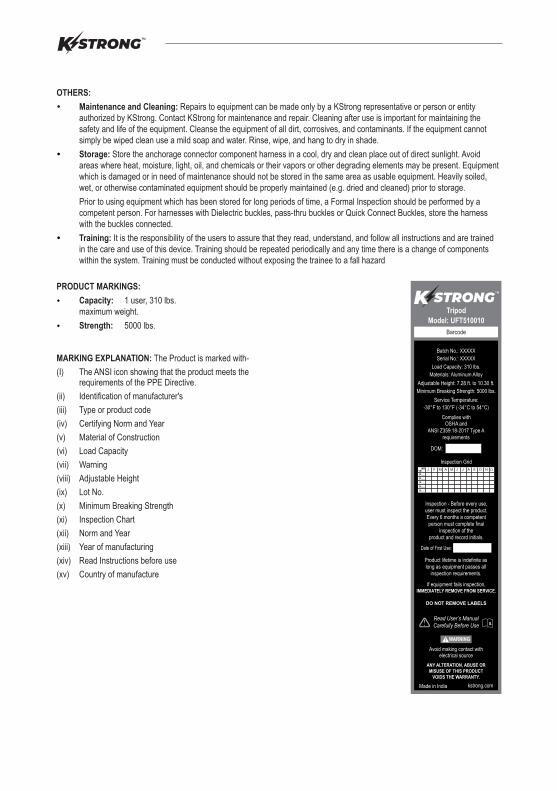
PRODUCT MARKINGS:
Capacity: 1 user, 310 lbs.maximum weight.
Strength: 5000 lbs.
Ÿ
Ÿ
OTHERS:
Ÿ Maintenance and Cleaning: Repairs to equipment can be made only by a KStrong representative or person or entity authorized by KStrong. Contact KStrong for maintenance and repair. Cleaning after use is important for maintaining the safety and life of the equipment. Cleanse the equipment of all dirt, corrosives, and contaminants. If the equipment cannot simply be wiped clean use a mild soap and water. Rinse, wipe, and hang to dry in shade.
Storage: Store the anchorage connector component harness in a cool, dry and clean place out of direct sunlight. Avoid areas where heat, moisture, light, oil, and chemicals or their vapors or other degrading elements may be present. Equipment which is damaged or in need of maintenance should not be stored in the same area as usable equipment. Heavily soiled, wet, or otherwise contaminated equipment should be properly maintained (e.g. dried and cleaned) prior to storage.
Prior to using equipment which has been stored for long periods of time, a Formal Inspection should be performed by a competent person. For harnesses with Dielectric buckles, pass-thru buckles or Quick Connect Buckles, store the harness with the buckles connected.
Training: It is the responsibility of the users to assure that they read, understand, and follow all instructions and are trained in the care and use of this device. Training should be repeated periodically and any time there is a change of components within the system. Training must be conducted without exposing the trainee to a fall hazard
Ÿ
Ÿ
MARKING EXPLANATION: The Product is marked with-
(I) The ANSI icon showing that the product meets the requirements of the PPE Directive.
(ii) Identification of manufacturer's
(iii) Type or product code
(iv) Certifying Norm and Year
(v) Material of Construction
(vi) Load Capacity
(vii) Warning
(viii) Adjustable Height
(ix) Lot No.
(x) Minimum Breaking Strength
(xi) Inspection Chart
(xii) Norm and Year
(xiii) Year of manufacturing
(xiv) Read Instructions before use
(xv) Country of manufacture
PERIODIC EXAMINATION: Keep these instructions with the product and fill in the identification sheet, entering the information taken from the markings.
The periodic examination is essential to test the resistance and condition of the equipment and to guarantee the safety of the user.
A qualified person must examine this equipment at least once each year in strict compliance with the instructions of the manufacturer and the previous check must be recorded on the attached sheet.
LIFESPAN: The estimated product Lifespan is 5 years from the date of first use. The following factors can reduce the Lifespan of the product: intense use, contact with chemical substances, specially aggressive environments, extreme temperature exposure, UV exposure, abrasions, cuts, violent impacts, bad use or maintenance.
DISCLAIMER:
Ÿ
Ÿ
Ÿ The frequency of inspection should be increased in accordance with the regulations, if the equipment is in heavy usage or if the equipment is used in harsh environments. Check also that the markings are legible.
Prior to use, the end user must read and understand the manufacturer's instructions supplied with this product at the time of shipment and seek training from their employer's trained personnel on the proper usage of the product. Manufacturer is not liable or responsible for any loss, damage or injury caused or incurred by any person on grounds of improper usage or installation of this product.
Periodic examinationnext due date
Product
Model & type/Identification
Trade Name
Address
Identification number
Manufacturer
Tel, email into use
Year of manufacture
Purchase Date
Date first put into use
Other relevant information (e.g. document number)
PERIODIC EXAMINATION AND REPAIR HISTORY
Date
Name and signature
of competent personReason for entry
(periodic examinationor repair)
Defects noted, repairs
relevant information carried out and other
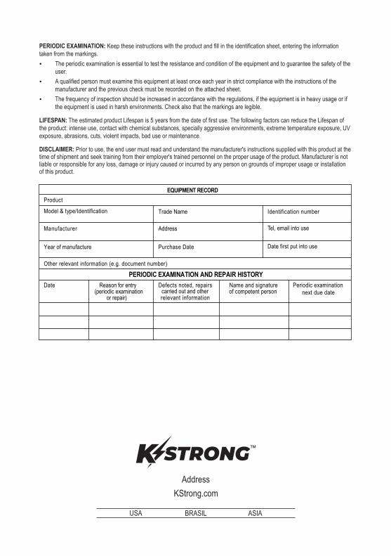
EQUIPMENT RECORD
Address
KStrong.com
USA BRASIL ASIA
Related Documents