Field Measuring Instruments 2019 Solutions for Maintenance, Repair and Operations

Welcome message from author
This document is posted to help you gain knowledge. Please leave a comment to let me know what you think about it! Share it to your friends and learn new things together.
Transcript
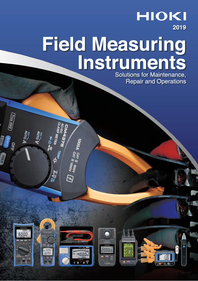
Field Measuring Instruments
2019
Solutions for Maintenance, Repair and Operations
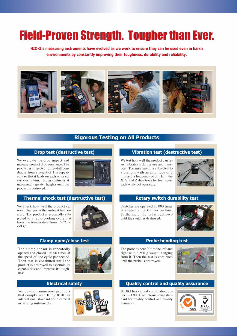
Field-Proven Strength. Tougher than Ever.HIOKI’s measuring instruments have evolved as we work to ensure they can be used even in harsh
environments by constantly improving their toughness, durability and reliability.
Rigorous Testing on All Products
Probe bending test
Rotary switch durability test
Quality control and quality assurance
HIOKI has earned certification un-der ISO 9001, an international stan-dard for quality control and quality assurance.
Switches are operated 10,000 times at a speed of 1,800 times per hour. Furthermore, the test is continued until the switch is destroyed.
The probe is bent 90° to the left and right with a 500 g weight hanging from it. Then the test is continued until the probe is destroyed.
Vibration test (destructive test)
We test how well the product can re-sist vibrations during use and trans-port. The instrument is subjected to vibrations with an amplitude of 2 mm and a frequency of 33 Hz in the X, Y, and Z directions for four hours each while not operating.
Clamp open/close test
Thermal shock test (destructive test)
We check how well the product can resist changes in the ambient temper-ature. The product is repeatedly sub-jected to a rapid-cooling cycle that takes the temperature from 150°C to -50°C.
The clamp sensor is repeatedly opened and closed 10,000 times at the speed of one cycle per second. Then test is continued until the product is destroyed to ascertain its capabilities and improve its tough-ness.
Drop test (destructive test)
We evaluate the drop impact and increase product drop resistance. The product is subjected to free-fall con-ditions from a height of 1 m repeat-edly so that it lands on each of its six surfaces in turn. Testing continues at increasingly greater heights until the product is destroyed.
Electrical safety
We develop numerous products that comply with IEC 61010, an international standard for electrical measuring instruments. IEC61010
Signal Generator, Battery Testers
Data Loggers
FieldMeasuring
PV Maintenance, LAN Cable Testers
Power Meters
Memory Recorders
DMM,Testers
ClampMeters
InsulationTesters
Other testing equipment
Other testing equipment
EnvironmentalMeasuring
Other testing equipment
TemperatureTesters
Contens
3
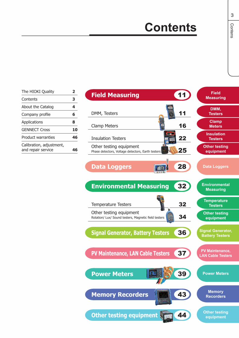
Field Measuring 11
Signal Generator, Battery Testers 36
Power Meters 39
Memory Recorders 43
Other testing equipment 44
11DMM, Testers
16Clamp Meters
22Insulation Testers
25Other testing equipmentPhase detectors, Voltage detectors, Earth testers
PV Maintenance, LAN Cable Testers 37
Data Loggers 28
Environmental Measuring 32
34Other testing equipmentRotation/ Lux/ Sound testers, Magnetic field testers
32Temperature Testers
Contents
2
3
4
6
8
10
46
46
The HIOKI Quality
Contents
About the Catalog
Company profile
Applications
GENNECT Cross
Product warranties
Calibration, adjustment, and repair service
4
About the catalog
About the Catalog
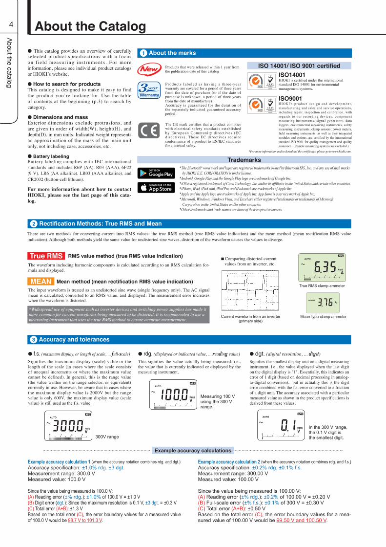
There are two methods for converting current into RMS values: the true RMS method (true RMS value indication) and the mean method (mean rectification RMS value indication). Although both methods yield the same value for undistorted sine waves, distortion of the waveform causes the values to diverge.
True RMSThe waveform including harmonic components is calculated according to an RMS calculation for-mula and displayed.
RMS value method (true RMS value indication)
The input waveform is treated as an undistorted sine wave (single frequency only). The AC signal mean is calculated, converted to an RMS value, and displayed. The measurement error increases when the waveform is distorted.
MEAN Mean method (mean rectification RMS value indication)
Current waveform from an inverter (primary side)
True RMS clamp ammeter
■ Comparing distorted current values from an inverter, etc.
Mean-type clamp ammeter
Rectification Methods: True RMS and Mean2
About the marks1
*Widespread use of equipment such as inverter devices and switching power supplies has made it more common for current waveforms being measured to be distorted. It is recommended to use a measuring instrument that uses the true RMS method to ensure accurate measurement.
Accuracy and tolerances3
l f.s. (maximum display, or length of scale, ... full-scale)Signifies the maximum display (scale) value or the length of the scale (in cases where the scale consists of unequal increments or where the maximum value cannot be defined). In general, this is the range value (the value written on the range selector, or equivalent) currently in use. However, be aware that in cases where the maximum display value is 2000V but the range value is only 600V, the maximum display value (scale value) is still used as the f.s. value.
300V range
l rdg. (displayed or indicated value, ... reading value)This signifies the value actually being measured, i.e., the value that is currently indicated or displayed by the measuring instrument.
Measuring 100 V using the 300 V range
l dgt. (digital resolution, ... digit)Signifies the smallest display unit on a digital measuring instrument, i.e., the value displayed when the last digit on the digital display is "1". Essentially, this indicates an error of 1 digit (based on decimal processing in analog-to-digital conversion), but in actuality this is the digit error combined with the f.s. error converted to a fraction of a digit unit. The accuracy associated with a particular measured value as shown in the product specifications is derived from these values.
In the 300 V range, the 0.1 V digit is the smallest digit.
Example accuracy calculations
Example accuracy calculation 1 (when the accuracy notation combines rdg. and dgt.)Accuracy specification: ±1.0% rdg. ±3 dgt.Measurement range: 300.0 VMeasured value: 100.0 V
Since the value being measured is 100.0 V:(A) Reading error (±% rdg.): ±1.0% of 100.0 V = ±1.0 V(B) Digit error (dgt.): Since the maximum resolution is 0.1 V, ±3 dgt. = ±0.3 V(C) Total error (A+B): ±1.3 VBased on the total error (C), the error boundary values for a measured value of 100.0 V would be 98.7 V to 101.3 V.
Example accuracy calculation 2 (when the accuracy notation combines rdg. and f.s.)Accuracy specification: ±0.2% rdg. ±0.1% f.s.Measurement range: 300.00 VMeasured value: 100.00 V
Since the value being measured is 100.00 V:(A) Reading error (±% rdg.): ±0.2% of 100.00 V = ±0.20 V(B) Full-scale error (±% f.s.): ±0.1% of 300 V = ±0.30 V(C) Total error (A+B): ±0.50 VBased on the total error (C), the error boundary values for a mea-sured value of 100.00 V would be 99.50 V and 100.50 V.
ISO 14001/ ISO 9001 certified
ISO9001H I O K I' s p r o d u c t d e s i g n a n d d e v e l o p m e n t , manufacturing and sales and service operations, including repair, inspection and calibration, with regards to our recording devices , component measuring instruments, signal generators, data loggers, environmental measuring instruments, safety measuring instruments, clamp sensors, power meters, field measuring instruments, as well as their integrated modules and options, are certified by the international standard ISO 9001 for quality management and quality assurance. (Remote measuring systems are excluded.)
ISO14001HIOKI is certified under the international standard ISO 14001 for environmental management systems.
*For more information and to download the certificates, please go to www.hioki.com.
l This catalog provides an overview of carefully selected product specifications with a focus on f ield measuring instruments. For more information, please see individual product catalogs or HIOKI’s website.
l How to search for productsThis catalog is designed to make it easy to find the product you’re looking for. Use the table of contents at the beginning (p.3) to search by category.
l Dimensions and massExterior dimensions exclude protrusions, and are given in order of width(W), height(H), and depth(D), in mm units. Indicated weight represents an approximation of the mass of the main unit only, not including case, accessories, etc.
l Battery labelingBattery labeling complies with IEC international standards and includes R6P (AA), R03 (AAA), 6F22 (9 V), LR6 (AA alkaline), LR03 (AAA alkaline), and CR2032 (button-cell lithium).
For more information about how to contact HIOKI, please see the last page of this cata-log.
*The Bluetooth® word mark and logos are registered trademarks owned by Bluetooth SIG, Inc. and any use of such marks by HIOKI E.E. CORPORATION is under license.
*Android, Google Play and the Google Play logo are trademarks of Google Inc.*iOS is a registered trademark of Cisco Technology, Inc. and/or its affiliates in the United States and certain other countries.*iPhone, iPad, iPad mini, iPad Pro and iPod touch are trademarks of Apple Inc.*Apple and the Apple logo are trademarks of Apple Inc. App Store is a service mark of Apple Inc.*Microsoft, Windows, Windows Vista, and Excel are either registered trademarks or trademarks of Microsoft
Corporation in the United States and/or other countries.*Other trademarks and trade names are those of their respective owners.
Trademarks
Products that were released within 1 year from the publication date of this catalog
Products labeled as having a three-year warranty are covered for a period of three years from the date of purchase (or if the date of purchase is unknown, a period of three years from the date of manufacture)Accuracy is guaranteed for the duration of the separately indicated guaranteed accuracy period.
The CE mark certifies that a product complies with electrical safety standards established by European Community directives (EC directives). These EC directives require conformance of a product to EN/IEC standards for electrical safety.
About the catalog
5
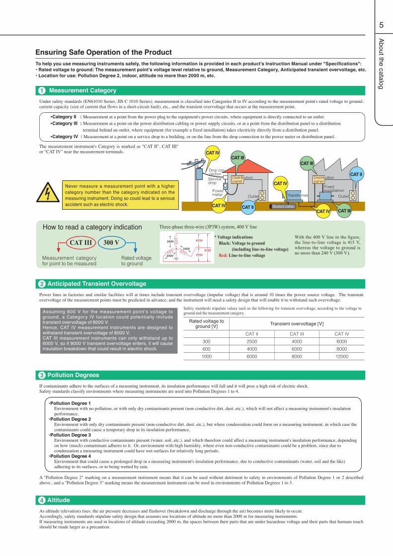
Never measure a measurement point with a higher category number than the category indicated on the measuring instrument. Doing so could lead to a serious accident such as electric shock.
Measurement Category1
To help you use measuring instruments safely, the following information is provided in each product's Instruction Manual under "Specifications":• Rated voltage to ground: The measurement point's voltage level relative to ground, Measurement Category, Anticipated transient overvoltage, etc.• Location for use: Pollution Degree 2, indoor, altitude no more than 2000 m, etc.
* Voltage indications Black: Voltage to ground (including line-to-line voltage) Red: Line-to-line voltage
With the 400 V line in the figure, the line-to-line voltage is 415 V, whereas the voltage to ground is no more than 240 V (300 V).
How to read a category indication
Measurement category for point to be measured
Rated voltage to ground
CAT III 300 V
Three-phase three-wire (3P3W) system, 400 V line
Under safety standards (EN61010 Series, JIS C 1010 Series), measurement is classified into Categories II to IV according to the measurement point's rated voltage to ground, current capacity (size of current that flows in a short-circuit fault), etc., and the transient overvoltage that occurs at the measurement point.
The measurement instrument's Category is marked as "CAT II", CAT III" or "CAT IV" near the measurement terminals.
A "Pollution Degree 2" marking on a measurement instrument means that it can be used without detriment to safety in environments of Pollution Degree 1 or 2 described above,, and a "Pollution Degree 3" marking means the measurement instrument can be used in environments of Pollution Degrees 1 to 3.
Anticipated Transient Overvoltage2Power lines in factories and similar facilities will at times include transient overvoltage (impulse voltage) that is around 10 times the power source voltage. The transient overvoltage of the measurement points must be predicted in advance, and the instrument will need a safety design that will enable it to withstand such overvoltage.
Assuming 600 V for the measurement point's voltage to ground, a Category IV location could potentially include transient overvoltage of 8000 V.Hence, CAT IV measurement instruments are designed to withstand transient overvoltage of 8000 V.CAT III measurement instruments can only withstand up to 6000 V, so if 8000 V transient overvoltage enters, it will cause insulation breakdown that could result in electric shock.
Pollution Degrees3
Altitude4
•Pollution Degree 1Environment with no pollution, or with only dry contaminants present (non-conductive dirt, dust, etc.), which will not affect a measuring instrument's insulation performance.
•Pollution Degree 2Environment with only dry contaminants present (non-conductive dirt, dust, etc.), but where condensation could form on a measuring instrument, in which case the contaminants could cause a temporary drop in its insulation performance.
•Pollution Degree 3Environment with conductive contaminants present (water, soil, etc.), and which therefore could affect a measuring instrument's insulation performance, depending on how (much) contaminant adheres to it. Or, environment with high humidity, where even non-conductive contaminants could be a problem, since due to condensation a measuring instrument could have wet surfaces for relatively long periods.
•Pollution Degree 4Environment that could cause a prolonged drop in a measuring instrument's insulation performance, due to conductive contaminants (water, soil and the like) adhering to its surfaces, or to being wetted by rain.
If contaminants adhere to the surfaces of a measuring instrument, its insulation performance will fall and it will pose a high risk of electric shock.Safety standards classify environments where measuring instruments are used into Pollution Degrees 1 to 4.
As altitude (elevation) rises, the air pressure decreases and flashover (breakdown and discharge through the air) becomes more likely to occur.Accordingly, safety standards stipulate safety design that assumes use locations of altitude no more than 2000 m for measuring instruments.If measuring instruments are used in locations of altitude exceeding 2000 m, the spaces between their parts that are under hazardous voltage and their parts that humans touch should be made larger as a precaution.
Safety standards stipulate values such as the following for transient overvoltage, according to the voltage to ground and the measurement category.
Rated voltage to ground [V] Transient overvoltage [V]
CAT II CAT III CAT IV300 2500 4000 6000600 4000 6000 8000
1000 6000 8000 12000
Ensuring Safe Operation of the Product
•Category II : Measurement at a point from the power plug to the equipment's power circuits, where equipment is directly connected to an outlet.•Category III : Measurement at a point on the power distribution cabling or power supply circuits, or at a point from the distribution panel to a distribution terminal behind an outlet, where equipment (for example a fixed installation) takes electricity directly from a distribution panel.•Category IV : Measurement at a point on a service drop to a building, or on the line from the drop connection to the power meter or distribution panel.

Com
pany profile
6
With all operations centralized at our Solution Factory,we aim to deliver high-quality products to customers across the globe.
SOLUTION FACTORYNagano
Electrical Measuring Instruments from Shinshu Ueda
In 2015, HIOKI celebrated the 80th anniversary of our founding in 1935. Going
forward, we remain committed to developing professional tools for electrical
measurement that deliver the solutions customers need. All development,
production, sales, and service departments are based at our Head Office
and manufacturing facilities in the lush region of Shinshu Ueda. By
keeping the full range of development and production in-house, we
confidently meet customer needs with unparalleled speed.
Vacuum deposition
Board population
Assembly
Customer Support
Repair and calibration
Shipment
In-house printing
Design
Board design
Development
DevelopmentDelivering high added
value through proprietary technologies
Empowering customers through
solutions-based sales
Production
Sales
Leveraging HIOKI's production system to
provide high-quality, low-cost products quickly

Com
pany profile
7
Electrical Measuring Instruments from Shinshu Ueda
Worldwide Sales and Service NetworkWorldwide Sales and Service Network
HIOKI WebsiteHIOKI Website
Following up on the establishment of HIOKI USA Corporation in the United States in 1998, we have continued to expand to local markets by establishing sales companies in China, Singapore, South Korea, Europe, as well as a service company in India. In addition, HIOKI operates representative offices in Taiwan and Dubai to provide a more immediate level of support for its distributors' sales activities. We also have the support of distributors in more than 30 countries, reflecting our effort to build sales structures for our products in every region of the world.
Sales or service subsidiary Sales subsidiary facilityPrincipal overseas distributor Representative office
For more information, please visit us at
www.hioki.com
Head Office
HIOKI USA Corporation
HIOKI SINGAPOREPte. Ltd.
Middle East
HIOKI India Engineering Private Limited
HIOKI EUROPEGmbH
HIOKI KOREACo., Ltd.
HIOKI TAIWANCo., Ltd.
HIOKI (Shanghai)Sales & TradingCo., Ltd.
ShenyangBeijingTianjin
Xi’an
ChengduWuhan
GuangzhouVietnam
ShenzhenThailand
MalaysiaHIOKI SINGAPORE Pte. Ltd.
Indonesia
HIOKI TAIWAN Co., Ltd.
HIOKI (Shanghai)Sales & Trading Co., Ltd.
HIOKI KOREA Co., Ltd.
Suzhou
JinanNanjing
CAT II
CAT IIICAT IV
Cubicle
Connection box
Solar panel
Solar panel
Junction box
Junction box
Distribution panel for lighting
Lights
Electrical outlet
Transformers
MCCB
Power line
Lighting line
8
Applications
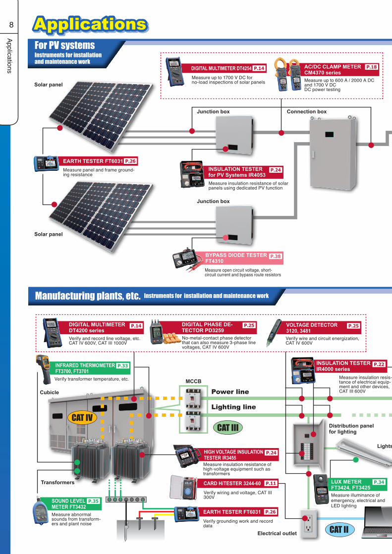
For PV systemsInstruments for installationand maintenance work
Manufacturing plants, etc. Instruments for installation and maintenance work
Verify transformer temperature, etc.
LUX METER FT3424, FT3425
P.34
Measure illuminance of emergency, electrical and LED lighting
HIGH VOLTAGE INSULATION TESTER IR3455
P.24
Measure insulation resistance of high-voltage equipment such as transformers
AC/DC CLAMP METER CM4370 series
P.18
Measure up to 600 A / 2000 A DCand 1700 V DCDC power testing
EARTH TESTER FT6031 P.26
Measure panel and frame ground-ing resistance
DIGITAL MULTIMETER DT4254 P.14
Measure up to 1700 V DC for no-load inspections of solar panels
Measure insulation resistance of solar panels using dedicated PV function
Verify wire and circuit energization, CAT IV 600V
DIGITAL MULTIMETER DT4200 series
P.14
Verify and record line voltage, etc.CAT IV 600V, CAT III 1000V
No-metal-contact phase detector that can also measure 3-phase line voltages, CAT IV 600V
Measure insulation resis-tance of electrical equip-ment and other devices, CAT III 600V
EARTH TESTER FT6031 P.26
Verify grounding work and record data
CARD HiTESTER 3244-60 P.11
Verify wiring and voltage, CAT III 300V
SOUND LEVEL METER FT3432
P.35
Measure abnormal sounds from transform-ers and plant noise
Applications
INSULATION TESTER for PV Systems IR4053
P.24
INFRARED THERMOMETER FT3700, FT3701
P.33
DIGITAL PHASE DE-TECTOR PD3259
P.25 VOLTAGE DETECTOR 3120, 3481
P.25
BYPASS DIODE TESTER FT4310
P.38
Measure open circuit voltage, short-circuit current and bypass route resistors
P.22INSULATION TESTERIR4000 series
Lights
Power conditioner
Cubicle
Air-conditioning power distribution
panel
Injection Molding Machine
Machine Tool
Air Handling Unit
Motor Driver
Welding robot
To grid
Transformer
Applications
9
Measure insulation resis-tance of electrical equip-ment and other devices, CAT III 600V
EARTH TESTER FT6031 P.26
Verify grounding work and record data
Measure air-conditioning tempera-ture
Measure motor RPM
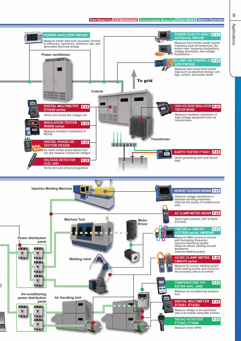
MEMORY HiCORDER MR8880 P.43
Observe voltage waveforms in injection-molding machinesImprove the quality of molded prod-ucts
AC CLAMP METER CM3289 P.16
Verify load currents, CAT III 600V (Current)
P.15
Measure voltage on the secondary side of an inverter using filter function
Measure and record time-series data such as electrical energy, volt-age, current, and power factor
POWER QUALITY ANALYZ-ER PQ3100, PW3198
P.41
CLAMP ON POWER LOG-GER PW3360
P.39
Measure and monitor power quality indicators such as harmonics, dis-tortion rate, frequency fluctuations, voltage anomalies, and voltage fluctuations
CM7290 or CM7291+CT7000 series +MR8880
P.42
Measure RMS current in circuits with fluctuating frequencyImprove machining qualityObserve robotic welding current waveformsImprove welding quality
TEMPERATURE HiT-ESTER 3441, 3442
P.32
TACHO HiTESTER FT3405, FT3406
P.33
AC/DC CLAMP METER CM4370 series
P.18
Measure DC current, welding current, motor starting current, and current on the secondary side of an inverter
P.14
Verify and record line voltage, etc.
VOLTAGE DETECTOR 3120, 3481
P.25
Verify wire and circuit energization
Measure insulation resistance of MCCB
DIGITAL PHASE DE-TECTOR PD3259
P.25
HIGH VOLTAGE INSULATION TESTER IR3455
P.24
No-metal-contact phase detector that can also measure 3-phase line voltages
POWER ANALYZER PW3390Measure power data such as power convert-er efficiency, harmonics, distortion rate, and generated electrical energy
Field Measuring Environmental MeasuringPV Maintenance Power Meters Memory Recorders
Measure insulation resistance of high-voltage equipment such as transformers
Power distribution panel
DIGITAL MULTIMETER DT4200 series
DIGITAL MULTIMETER DT4281, DT4282
P.22INSULATION TESTERIR4000 series
GEN
NEC
T Cross
10
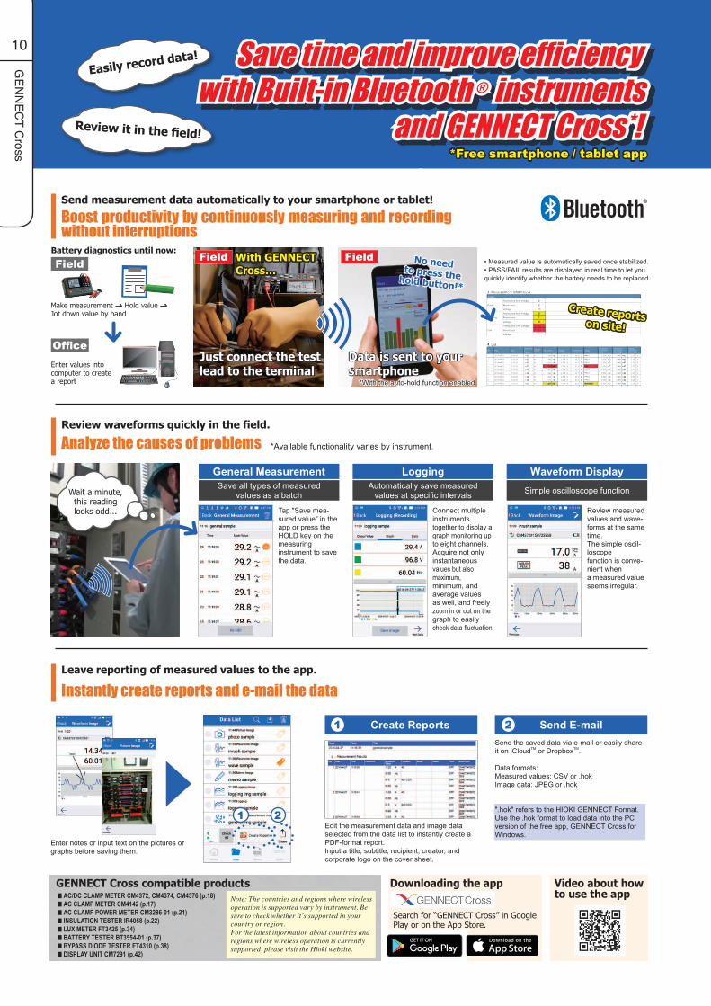
• Measured value is automatically saved once stabilized.• PASS/FAIL results are displayed in real time to let you quickly identify whether the battery needs to be replaced.
Send measurement data automatically to your smartphone or tablet!
Boost productivity by continuously measuring and recording without interruptions
Review waveforms quickly in the field.
Analyze the causes of problems
Leave reporting of measured values to the app.
Instantly create reports and e-mail the data
General MeasurementSave all types of measured
values as a batch
Tap "Save mea-sured value" in the app or press the HOLD key on the measuringinstrument to save the data.
LoggingAutomatically save measured
values at specific intervals
Connect multiple instrumentstogether to display a graph monitoring up to eight channels.Acquire not only instantaneousvalues but also maximum,minimum, and average valuesas well, and freely zoom in or out on the graph to easilycheck data fluctuation.
Waveform DisplaySimple oscilloscope function
Review measured values and wave-forms at the same time.The simple oscil-loscopefunction is conve-nient whena measured value seems irregular.
*Available functionality varies by instrument.
Enter notes or input text on the pictures or graphs before saving them.
1 2
Create Reports1 Send E-mail2
Edit the measurement data and image data selected from the data list to instantly create a PDF-format report.Input a title, subtitle, recipient, creator, and corporate logo on the cover sheet.
Send the saved data via e-mail or easily share it on iCloudTM or DropboxTM.
Data formats:Measured values: CSV or .hokImage data: JPEG or .hok
".hok" refers to the HIOKI GENNECT Format.Use the .hok format to load data into the PC version of the free app, GENNECT Cross for Windows.
Battery diagnostics until now:
Field
Office
Make measurement → Hold value → Jot down value by hand
Just connect the test lead to the terminal
Data is sent to your smartphone
With GENNECT Cross…
No needto press the hold button!*
Enter values into computer to create a report
Field Field
Wait a minute, this reading looks odd...
Easily record data!
Review it in the field!
Save time and improve efficiency with Built-in Bluetooth ® instruments
and GENNECT Cross*!*Free smartphone / tablet app
GENNECT Cross compatible products Downloading the app Video about how to use the app
Search for “GENNECT Cross” in Google Play or on the App Store.
n AC/DC CLAMP METER CM4372, CM4374, CM4376 (p.18)n AC CLAMP METER CM4142 (p.17)n AC CLAMP POWER METER CM3286-01 (p.21)n INSULATION TESTER IR4058 (p.22)n LUX METER FT3425 (p.34)n BATTERY TESTER BT3554-01 (p.37)n BYPASS DIODE TESTER FT4310 (p.38)n DISPLAY UNIT CM7291 (p.42)
Note: The countries and regions where wireless operation is supported vary by instrument. Be sure to check whether it’s supported in your country or region.For the latest information about countries and regions where wireless operation is currently supported, please visit the Hioki website.
Create reports on site!
*With the auto-hold function enabled
11
DM
M, Testers
ANALOG/ POCKET
Test lead fits neatly into back of instrument
3246-70: Skeleton model (blue)
Basic Analog Tester(20kΩ/V)
HiTESTER 3030-10
*Note: This system is not for protecting the instrument from damage but for securing safety.
New insulated test pin sleeves prevents short-circuits
Note: With cap removed, operates as a CAT II device. For more information, please see above.Note: When measuring in a CAT III environment, be sure to attach the sleeve to the test leads.
Note: The temperature scale on Model 3030-10 is not effective without Model 9021-01 tem-perature probe, which has been discontinued.
DC300mA
AC/DC600V 3MΩ
■ Basic specifications (Accuracy guaranteed for 1 year, Post-adjustment accuracy guaranteed for 1 year)
AccessoriesSpare fuse
R6P manganesebattery×2
Instructionmanual
CARRYINGCASE9390
HIGH-VOLTAGE PROBE 9017(Not CE marked)
TEST LEAD L9207-30
Options
DC voltage 0 to 0.3/3/12/30/120/300/600 VAccuracy ±2.5 % of f.s. readingAC voltage 0 to 12/30/120/300/600 VAccuracy ±2.5 % of f.s. reading (12V: ±4 %)DC current 0 to 60 μA/30/300 mAAccuracy ±3 % of f.s. readingResistance 0 to 3kΩ, R×1/×10/×100/×1kAccuracy ±3 % of scale length
Protective systemShort circuit protection of power line by fuse* (up to 250 VAC commercial power input), Overload protection of meter device by diode
Functions Battery checkDrop proof 4
Power supply For resistance measurement range, R6P (AA) manganese battery× 2
Dimensions and mass
95 mm (3.74 in) W × 141 mm (5.55 in) H × 39 mm (1.54 in) D, 280 g (9.9 oz)
Measurem
ent rangeFunctions
Sleeve attached
Order Code: 3030-10
Compact ! Palm Size Body, Less Than 1cm Thin!
Cable length:46 cm (17.7 in)
Pencil-type DMM with LED light
Note: When measuring in a CAT IV or CAT III environment, be sure to attach the sleeve to the test leads.
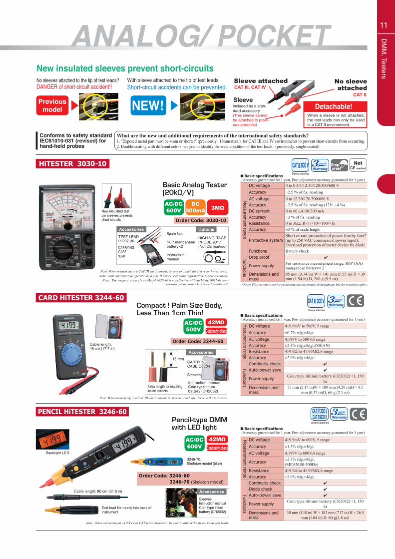
New insulated sleeves prevent short-circuitsNo sleeves attached to the tip of test leads?DANGER of short-circuit accident!!
Previousmodel
s
NEW!
s
With sleeve attached to the tip of test leads,Short-circuit accidents can be prevented.
Detachable!When a sleeve is not attached, the test leads can only be used in a CAT II environment.
included as a stan-dard accessory(This sleeve cannot be attached to previ-ous products)
Sleeve
Sleeve attachedCAT III, CAT IV
No sleeve attached
CAT II
Conforms to safety standardIEC61010-031 (revised) for hand-held probes
What are the new and additional requirements of the international safety standards?1. "Exposed metal part must be 4mm or shorter" (previously, 19mm max.) for CAT III and IV environments to prevent short-circuits from occurring.2. Double-coating with different colors lets you to identify the wear condition of the test leads. (previously, single-coated)
DC voltage 419.9mV to 500V, 5 rangeAccuracy ±0.7% rdg.±4dgt.AC voltage 4.199V to 500V,4 rangeAccuracy ±2.3% rdg.±8dgt.(MEAN)Resistance 419.9Ω to 41.99MΩ,6 rangeAccuracy ±2.0% rdg.±4dgt.Continuity check 4
Auto-power save 4
Power supplyCoin type lithium battery (CR2032) ×1, 150
hrDimensions and mass
55 mm (2.17 in)W × 109 mm (4.29 in)H × 9.5 mm (0.37 in)D, 60 g (2.1 oz)
DC voltage 419.9mV to 600V, 5 rangeAccuracy ±1.3% rdg.±4dgt.AC voltage 4.199V to 600V,4 range
Accuracy±2.3% rdg.±8dgt.(MEAN,50-500Hz)
Resistance 419.9Ω to 41.99MΩ,6 rangeAccuracy ±2.0% rdg.±4dgt.Continuity check 4
Diode check 4
Auto-power save 4
Power supplyCoin type lithium battery (CR2032) ×1, 150
hrDimensions and mass
30 mm (1.18 in) W × 182 mm (7.17 in) H × 26.5 mm (1.04 in) D, 80 g(2.8 oz)
CARD HiTESTER 3244-60
PENCIL HiTESTER 3246-60
Sleeve attached
AC/DC500V
42MΩContinuity check
Order Code: 3244-60
Extra length for reaching inside sockets
15 mmAccessories
Instruction manual Coin type litiumbattery (CR2032)
CARRYINGCASE C0204
Sleeves
CARRYINGCASE C0204
Sleeves
Note: When measuring in a CAT III environment, be sure to attach the sleeve to the test leads.
■ Basic specifications (Accuracy guaranteed for 1 year, Post-adjustment accuracy guaranteed for 1 year)
Backlight LED
Cable length: 80 cm (31.5 in)
Order Code: 3246-60 3246-70 (Skeleton model)
LED light
SleevesInstruction manual Coin type litiumbattery (CR2032)
Accessories
■ Basic specifications (Accuracy guaranteed for 1 year, Post-adjustment accuracy guaranteed for 1 year)
Sleeve attached
AC/DC600V
42MΩContinuity check
Measurem
ent rangeM
easurement range
FunctionsFunctions
12
DM
M, Testers
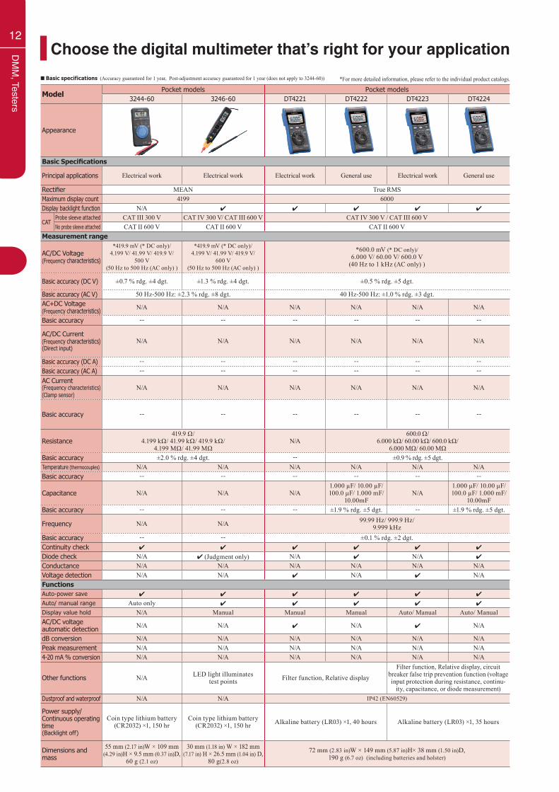
Choose the digital multimeter that’s right for your application*For more detailed information, please refer to the individual product catalogs.■ Basic specifications (Accuracy guaranteed for 1 year, Post-adjustment accuracy guaranteed for 1 year (does not apply to 3244-60))
ModelPocket models Pocket models
3244-60 3246-60 DT4221 DT4222 DT4223 DT4224
Appearance
Basic Specifications
Principal applications Electrical work Electrical work Electrical work General use Electrical work General use
Rectifier MEAN True RMSMaximum display count 4199 6000Display backlight function N/A 4 4 4 4 4
CATProbe sleeve attached CAT III 300 V CAT IV 300 V/ CAT III 600 V CAT IV 300 V / CAT III 600 VNo probe sleeve attached CAT II 600 V CAT II 600 V CAT II 600 V
Measurement range
AC/DC Voltage(Frequency characteristics)
*419.9 mV (* DC only)/4.199 V/ 41.99 V/ 419.9 V/
500 V(50 Hz to 500 Hz (AC only) )
*419.9 mV (* DC only)/4.199 V/ 41.99 V/ 419.9 V/
600 V(50 Hz to 500 Hz (AC only) )
*600.0 mV (* DC only)/6.000 V/ 60.00 V/ 600.0 V
(40 Hz to 1 kHz (AC only) )
Basic accuracy (DC V) ±0.7 % rdg. ±4 dgt. ±1.3 % rdg. ±4 dgt. ±0.5 % rdg. ±5 dgt.
Basic accuracy (AC V) 50 Hz-500 Hz: ±2.3 % rdg. ±8 dgt. 40 Hz-500 Hz: ±1.0 % rdg. ±3 dgt.AC+DC Voltage(Frequency characteristics) N/A N/A N/A N/A N/A N/A
Basic accuracy -- -- -- -- -- --
AC/DC Current(Frequency characteristics)(Direct input)
N/A N/A N/A N/A N/A N/A
Basic accuracy (DC A) -- -- -- -- -- --Basic accuracy (AC A) -- -- -- -- -- --AC Current(Frequency characteristics)(Clamp sensor)
N/A N/A N/A N/A N/A N/A
Basic accuracy -- -- -- -- -- --
Resistance419.9 Ω/
4.199 kΩ/ 41.99 kΩ/ 419.9 kΩ/4.199 MΩ/ 41.99 MΩ
N/A600.0 Ω/
6.000 kΩ/ 60.00 kΩ/ 600.0 kΩ/6.000 MΩ/ 60.00 MΩ
Basic accuracy ±2.0 % rdg. ±4 dgt. -- ±0.9 % rdg. ±5 dgt.Temperature (thermocouples) N/A N/A N/A N/A N/A N/ABasic accuracy -- -- -- -- -- --
Capacitance N/A N/A N/A1.000 µF/ 10.00 µF/ 100.0 µF/ 1.000 mF/
10.00mFN/A
1.000 µF/ 10.00 µF/ 100.0 µF/ 1.000 mF/
10.00mFBasic accuracy -- -- -- ±1.9 % rdg. ±5 dgt. -- ±1.9 % rdg. ±5 dgt.
Frequency N/A N/A 99.99 Hz/ 999.9 Hz/9.999 kHz
Basic accuracy -- -- ±0.1 % rdg. ±2 dgt.Continuity check 4 4 4 4 4 4
Diode check N/A 4 (Judgment only) N/A 4 N/A 4
Conductance N/A N/A N/A N/A N/A N/AVoltage detection N/A N/A 4 N/A 4 N/AFunctionsAuto-power save 4 4 4 4 4 4
Auto/ manual range Auto only 4 4 4 4 4
Display value hold N/A Manual Manual Manual Auto/ Manual Auto/ ManualAC/DC voltageautomatic detection N/A N/A 4 N/A 4 N/A
dB conversion N/A N/A N/A N/A N/A N/APeak measurement N/A N/A N/A N/A N/A N/A4-20 mA % conversion N/A N/A N/A N/A N/A N/A
Other functions N/A LED light illuminatestest points Filter function, Relative display
Filter function, Relative display, circuit breaker false trip prevention function (voltage input protection during resistance, continu-
ity, capacitance, or diode measurement)Dustproof and waterproof N/A N/A IP42 (EN60529)
Power supply/Continuous operating time(Backlight off)
Coin type lithium battery (CR2032) ×1, 150 hr
Coin type lithium battery (CR2032) ×1, 150 hr Alkaline battery (LR03) ×1, 40 hours Alkaline battery (LR03) ×1, 35 hours
Dimensions and mass
55 mm (2.17 in)W × 109 mm (4.29 in)H × 9.5 mm (0.37 in)D,
60 g (2.1 oz)
30 mm (1.18 in) W × 182 mm (7.17 in) H × 26.5 mm (1.04 in) D,
80 g(2.8 oz)
72 mm (2.83 in)W × 149 mm (5.87 in)H× 38 mm (1.50 in)D, 190 g (6.7 oz) (including batteries and holster)
13
DM
M, Testers
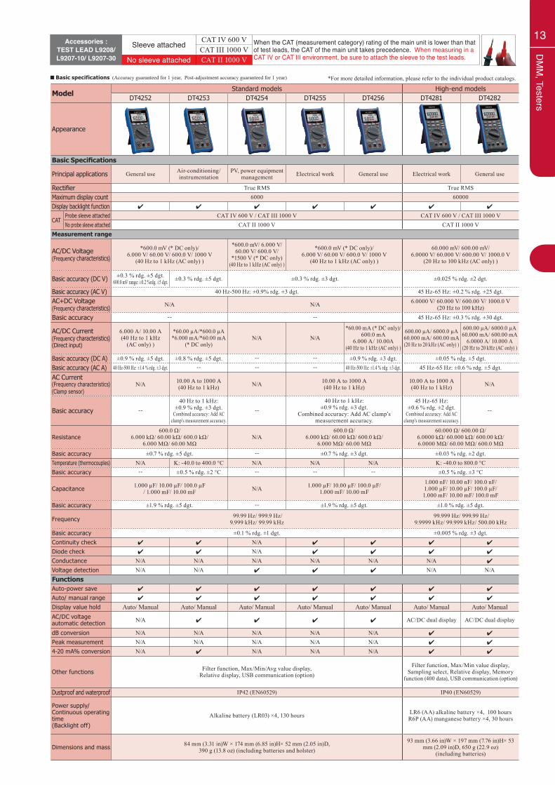
■ Basic specifications (Accuracy guaranteed for 1 year, Post-adjustment accuracy guaranteed for 1 year) *For more detailed information, please refer to the individual product catalogs.
ModelStandard models High-end models
DT4252 DT4253 DT4254 DT4255 DT4256 DT4281 DT4282
Appearance
Basic Specifications
Principal applications General use Air-conditioning/instrumentation
PV, power equipment management Electrical work General use Electrical work General use
Rectifier True RMS True RMSMaximum display count 6000 60000Display backlight function 4 4 4 4 4 4 4
CATProbe sleeve attached CAT IV 600 V / CAT III 1000 V CAT IV 600 V / CAT III 1000 VNo probe sleeve attached CAT II 1000 V CAT II 1000 V
Measurement range
AC/DC Voltage(Frequency characteristics)
*600.0 mV (* DC only)/6.000 V/ 60.00 V/ 600.0 V/ 1000 V
(40 Hz to 1 kHz (AC only) )
*600.0 mV/ 6.000 V/ 60.00 V/ 600.0 V/
*1500 V (* DC only)(40 Hz to 1 kHz (AC only) )
*600.0 mV (* DC only)/6.000 V/ 60.00 V/ 600.0 V/ 1000 V
(40 Hz to 1 kHz (AC only) )
60.000 mV/ 600.00 mV/6.0000 V/ 60.000 V/ 600.00 V/ 1000.0 V
(20 Hz to 100 kHz (AC only) )
Basic accuracy (DC V) ±0.3 % rdg. ±5 dgt.600.0 mV range: ±0.2 %rdg. ±5 dgt. ±0.3 % rdg. ±5 dgt. ±0.3 % rdg. ±3 dgt. ±0.025 % rdg. ±2 dgt.
Basic accuracy (AC V) 40 Hz-500 Hz: ±0.9% rdg. ±3 dgt. 45 Hz-65 Hz: ±0.2 % rdg. ±25 dgt.AC+DC Voltage(Frequency characteristics) N/A N/A 6.0000 V/ 60.000 V/ 600.00 V/ 1000.0 V
(20 Hz to 100 kHz)
Basic accuracy -- -- 45 Hz-65 Hz: ±0.3 % rdg. ±30 dgt.
AC/DC Current(Frequency characteristics)(Direct input)
6.000 A/ 10.00 A(40 Hz to 1 kHz
(AC only) )
*60.00 µA/*600.0 µA*6.000 mA/*60.00 mA
(* DC only)N/A N/A
*60.00 mA (* DC only)/600.0 mA
6.000 A/ 10.00A(40 Hz to 1 kHz (AC only) )
600.00 µA/ 6000.0 µA60.000 mA/ 600.00 mA(20 Hz to 20 kHz (AC only) )
600.00 µA/ 6000.0 µA60.000 mA/ 600.00 mA
6.0000 A/ 10.000 A(20 Hz to 20 kHz (AC only) )
Basic accuracy (DC A) ±0.9 % rdg. ±5 dgt. ±0.8 % rdg. ±5 dgt. -- -- ±0.9 % rdg. ±3 dgt. ±0.05 % rdg. ±5 dgt.Basic accuracy (AC A) 40 Hz-500 Hz: ±1.4 % rdg. ±3 dgt. -- -- -- 40 Hz-500 Hz: ±1.4 % rdg. ±3 dgt. 45 Hz-65 Hz: ±0.6 % rdg. ±5 dgt.
AC Current(Frequency characteristics)(Clamp sensor)
N/A 10.00 A to 1000 A(40 Hz to 1 kHz) N/A 10.00 A to 1000 A
(40 Hz to 1 kHz)10.00 A to 1000 A(40 Hz to 1 kHz) N/A
Basic accuracy --40 Hz to 1 kHz:
±0.9 % rdg. ±3 dgt.Combined accuracy: Add AC
clamp’s measurement accuracy.
--40 Hz to 1 kHz:
±0.9 % rdg. ±3 dgt.Combined accuracy: Add AC clamp’s
measurement accuracy.
45 Hz-65 Hz: ±0.6 % rdg. ±2 dgt.
Combined accuracy: Add AC clamp’s measurement accuracy.
--
Resistance600.0 Ω/
6.000 kΩ/ 60.00 kΩ/ 600.0 kΩ/6.000 MΩ/ 60.00 MΩ
N/A600.0 Ω/
6.000 kΩ/ 60.00 kΩ/ 600.0 kΩ/6.000 MΩ/ 60.00 MΩ
60.000 Ω/ 600.00 Ω/6.0000 kΩ/ 60.000 kΩ/ 600.00 kΩ/6.0000 MΩ/ 60.00 MΩ/ 600.0 MΩ
Basic accuracy ±0.7 % rdg. ±5 dgt. -- ±0.7 % rdg. ±3 dgt. ±0.03 % rdg. ±2 dgt.Temperature (thermocouples) N/A K: -40.0 to 400.0 °C N/A N/A N/A K: -40.0 to 800.0 °C Basic accuracy -- ±0.5 % rdg. ±2 °C -- -- -- ±0.5 % rdg. ±3 °C
Capacitance 1.000 µF/ 10.00 µF/ 100.0 µF/ 1.000 mF/ 10.00 mF N/A 1.000 µF/ 10.00 µF/ 100.0 µF/
1.000 mF/ 10.00 mF
1.000 nF/ 10.00 nF/ 100.0 nF/1.000 µF/ 10.00 µF/ 100.0 µF/1.000 mF/ 10.00 mF/ 100.0 mF
Basic accuracy ±1.9 % rdg. ±5 dgt. -- ±1.9 % rdg. ±5 dgt. ±1.0 % rdg. ±5 dgt.
Frequency 99.99 Hz/ 999.9 Hz/9.999 kHz/ 99.99 kHz
99.999 Hz/ 999.99 Hz/9.9999 kHz/ 99.999 kHz/ 500.00 kHz
Basic accuracy ±0.1 % rdg. ±1 dgt. ±0.005 % rdg. ±3 dgt.Continuity check 4 4 N/A 4 4 4 4
Diode check 4 4 N/A 4 4 4 4
Conductance N/A N/A N/A N/A N/A N/A 4
Voltage detection N/A N/A 4 4 4 N/A N/AFunctionsAuto-power save 4 4 4 4 4 4 4
Auto/ manual range 4 4 4 4 4 4 4
Display value hold Auto/ Manual Auto/ Manual Auto/ Manual Auto/ Manual Auto/ Manual Auto/ Manual Auto/ ManualAC/DC voltageautomatic detection N/A 4 4 4 4 AC/DC dual display AC/DC dual display
dB conversion N/A N/A N/A N/A N/A 4 4
Peak measurement N/A N/A N/A N/A N/A 4 4
4-20 mA% conversion N/A 4 N/A N/A N/A 4 4
Other functions Filter function, Max/Min/Avg value display, Relative display, USB communication (option)
Filter function, Max/Min value display, Sampling select, Relative display, Memory
function (400 data), USB communication (option)
Dustproof and waterproof IP42 (EN60529) IP40 (EN60529)
Power supply/Continuous operating time(Backlight off)
Alkaline battery (LR03) ×4, 130 hours LR6 (AA) alkaline battery ×4, 100 hoursR6P (AA) manganese battery ×4, 30 hours
Dimensions and mass 84 mm (3.31 in)W × 174 mm (6.85 in)H× 52 mm (2.05 in)D, 390 g (13.8 oz) (including batteries and holster)
93 mm (3.66 in)W × 197 mm (7.76 in)H× 53 mm (2.09 in)D, 650 g (22.9 oz)
(including batteries)
Accessories :TEST LEAD L9208/ L9207-10/ L9207-30
Sleeve attached CAT IV 600 V When the CAT (measurement category) rating of the main unit is lower than that of test leads, the CAT of the main unit takes precedence. When measuring in a CAT IV or CAT III environment, be sure to attach the sleeve to the test leads.
CAT III 1000 VNo sleeve attached CAT II 1000 V
14
DM
M, Testers
DIGITAL MULTIMETERDT4252, DT4253, DT4254, DT4255, DT4256
Standard modelsIntroducing a line of field-optimized instruments that can be chosen based on the application at hand
• Standard DMM that Delivers Top Safety and Reliability• High-speed 0.9 s response for AC voltage measurement
DT4255: Use as a replacement for the Digital HiTester 3255-50 (discontinued).
Sleeve attached DT4254/55/56
Specifications (Function/ Range)
DC Voltage600.0mV - 1000V 4 4 4 4 4
1700V N/A N/A 4 N/A N/AAC Voltage 6.000V - 1000V 4 4 4 4 4
AC/DC voltage automatic detection 600.0V N/A 4 4 4 4
DC Current
60.00μA - 60.00mA N/A 4 N/A N/A N/A60.00mA - 600.0mA N/A N/A N/A N/A 4
6.000A - 10.00A 4 N/A N/A N/A 4
AC Current600.0mA N/A N/A N/A N/A 4
6.000A - 10.00A 4 N/A N/A N/A 4
AC Current (Clamp sensor) 10.00A - 1000A N/A 4 N/A 4 4
Resistance 600.0Ω - 60.00MΩ 4 4 N/A 4 4
Temperature (thermocouples) -40.0 ˚C - +400.0 ˚C N/A 4 N/A N/A N/ACapacitance 1.000uF - 10.00mF 4 4 N/A 4 4
Frequency 99.99Hz - 99.99kHz 4 4 4 4 4
Continuity check 600.0Ω 4 4 N/A 4 4
Diode check 1.500V 4 4 N/A 4 4
Voltage detection Hi/Lo N/A N/A 4 4 4
Model (DT42 ) 52 53 54 55 56Features
CAT III 1000V, CAT IV 600V 4 4 4 4 4
No current terminals (to prevent short-circuits) N/A N/A 4 4 N/AVoltage measurement function only N/A N/A 4 N/A N/AVoltage measurement terminals with current-limiting resistor and fast-blow fuse N/A N/A N/A 4 N/AHigh-speed 0.9 s response for AC voltage measurement 4 4 4 4 4
AC/DC voltage automatic detection N/A 4 4 4 4
1700 V DC measurement (for measuring solar panel open-circuit voltage) N/A N/A 4 N/A N/AHigh-precision mV measurement at ±0.2% rdg. 4 N/A N/A N/A N/AVery low current (μA/mA)/ Temperature measurement N/A 4 N/A N/A N/AUSB communications function supports PC measurements (optional) 4 4 4 4 4
Dual display lets you check voltage and frequency simultaneously/ Backlight 4 4 4 4 4
Broad -25°C (-13°F) to 65°C (149°F) operating temperature range N/A N/A 4 4 4
SafetyO
thersM
easurement
Order Code: DT4252 (For laboratory and research use) DT4253 (For instrumentation 4-20mA) DT4254 (Voltage measurement only model) DT4255 (For electrical work in the field) DT4256 (Multifunction model)
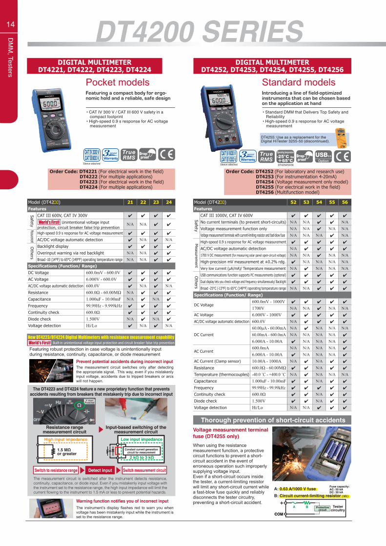
DT4200 SERIESDIGITAL MULTIMETER
DT4221, DT4222, DT4223, DT4224
Pocket modelsFeaturing a compact body for ergo-nomic hold and a reliable, safe design
• CAT IV 300 V / CAT III 600 V safety in a compact footprint• High-speed 0.9 s response for AC voltage measurement
Prevent potential accidents during incorrect inputThe measurement circuit switches only after detecting the appropriate signal. This way, even if you mistakenly input voltage, accidents due to tripped breakers or arcs will not happen.
Featuring robust protection in case voltage is unintentionally input during resistance, continuity, capacitance, or diode measurement
Warning function notifies you of incorrect inputThe instrument’s display flashes red to warn you when voltage has been mistakenly input while the instrument is set to the resistance range.
Sleeve attached
Order Code: DT4221 (For electrical work in the field) DT4222 (For multiple applications) DT4223 (For electrical work in the field) DT4224 (For multiple applications)
Specifications (Function/ Range)DC Voltage 600.0mV - 600.0V 4 4 4 4
AC Voltage 6.000V - 600.0V 4 4 4 4
AC/DC voltage automatic detection 600.0V 4 N/A 4 N/AResistance 600.0Ω - 60.00MΩ N/A 4 4 4
Capacitance 1.000uF - 10.00mF N/A 4 N/A 4
Frequency 99.99Hz - 9.999kHz 4 4 4 4
Continuity check 600.0Ω 4 4 4 4
Diode check 1.500V N/A 4 N/A 4
Voltage detection Hi/Lo 4 N/A 4 N/A
Model (DT42 ) 21 22 23 24Features
CAT III 600V, CAT IV 300V 4 4 4 4
Unintentional voltage input protection, circuit breaker false trip prevention
N/A N/A 4 4
High-speed 0.9 s response for AC voltage measurement 4 4 4 4
AC/DC voltage automatic detection 4 N/A 4 N/A
Backlight display 4 4 4 4
Overinput warning via red backlight N/A N/A 4 4
Broad -10 (14°F) to 65°C (149°F) operating temperature range N/A N/A 4 4
SafetyO
thersMeasurement
World's First!
New DT4223/DT4224 Digital Multimeters with resistance measurement capability Built-in unintentional voltage input protection and circuit breaker false trip preventionWorld's First!
Switch to resistance range Switch measurement circuitThe measurement circuit is switched after the instrument detects resistance, continuity, capacitance, or diode input. Even if you mistakenly input voltage with the instrument set to the resistance range, the high input impedance will limit the current flowing to the instrument to 1.5 mA or less to prevent potential hazards.
Detect input
Resistance range measurement circuit
Input-based switching of the measurement circuit
High input impedance
1.5 MΩ or greater
Low input impedance
Constant current generationcircuit for measurement
2 kΩ to 3 kΩ
The DT4223 and DT4224 feature a new proprietary function that prevents accidents resulting from breakers that mistakenly trip due to incorrect input
Thorough prevention of short-circuit accidents
When using the resistance measurement function, a protective circuit functions to prevent a short-circuit accident in the event of erroneous operation such improperly supplying voltage input.Even if a short-circuit occurs inside the tester, a current-limiting resistor will limit any short-circuit current while a fast-blow fuse quickly and reliably disconnects the tester circuitry, preventing a short-circuit accident.
A: 0.63 A/1000 V fuseB: Circuit current-limiting resistor ( 5Ω )
COM
BA+
Testercircuitry
Protectivecircuit
Fuse capacity: AC: 50 kADC: 30 kA
Voltage measurement terminal fuse (DT4255 only)
15
DM
M, Testers
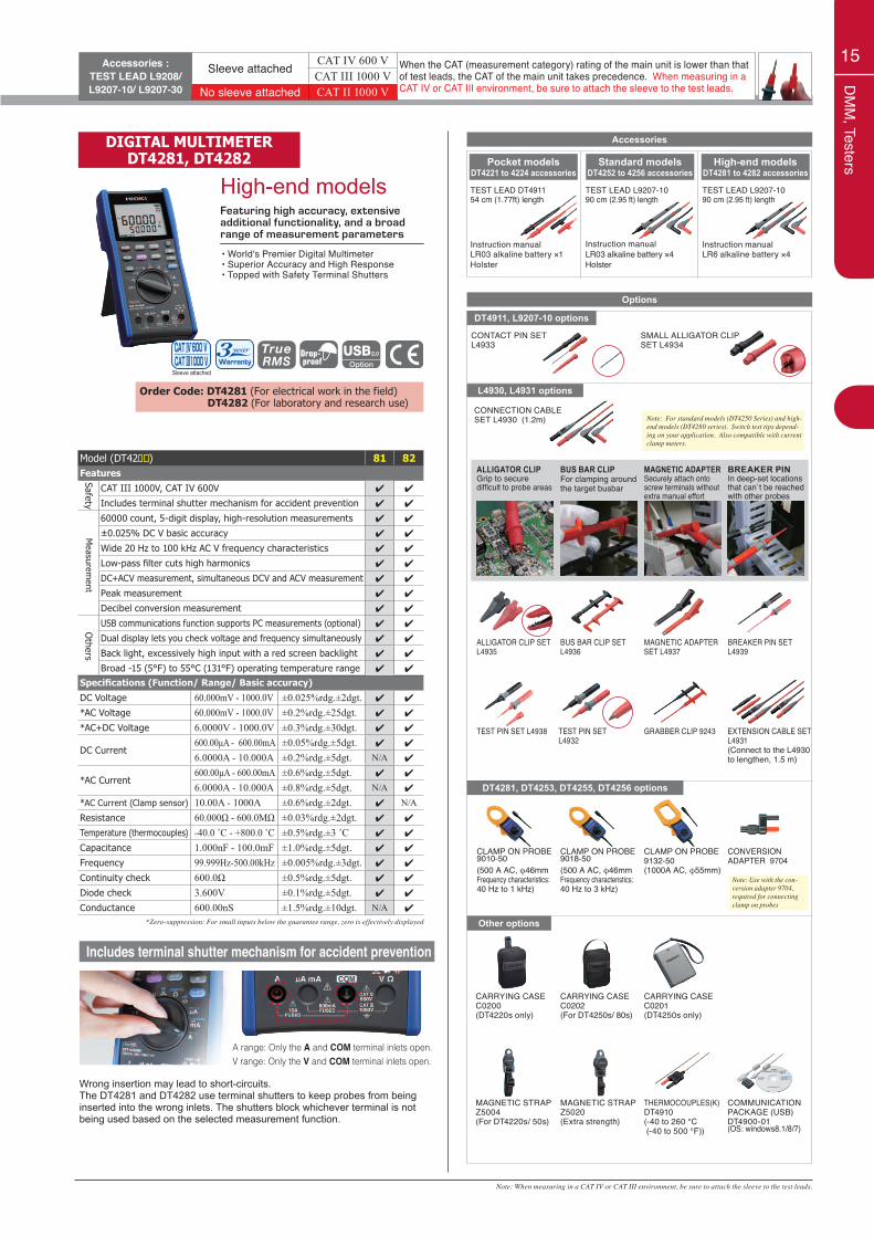
DIGITAL MULTIMETERDT4281, DT4282
High-end modelsFeaturing high accuracy, extensive additional functionality, and a broad range of measurement parameters
• World's Premier Digital Multimeter • Superior Accuracy and High Response• Topped with Safety Terminal Shutters
Sleeve attached
Specifications (Function/ Range/ Basic accuracy)DC Voltage 60.000mV - 1000.0V ±0.025%rdg.±2dgt. 4 4
*AC Voltage 60.000mV - 1000.0V ±0.2%rdg.±25dgt. 4 4
*AC+DC Voltage 6.0000V - 1000.0V ±0.3%rdg.±30dgt. 4 4
DC Current600.00μA - 600.00mA ±0.05%rdg.±5dgt. 4 4
6.0000A - 10.000A ±0.2%rdg.±5dgt. N/A 4
*AC Current600.00μA - 600.00mA ±0.6%rdg.±5dgt. 4 4
6.0000A - 10.000A ±0.8%rdg.±5dgt. N/A 4
*AC Current (Clamp sensor) 10.00A - 1000A ±0.6%rdg.±2dgt. 4 N/AResistance 60.000Ω - 600.0MΩ ±0.03%rdg.±2dgt. 4 4
Temperature (thermocouples) -40.0 ˚C - +800.0 ˚C ±0.5%rdg.±3 ˚C 4 4
Capacitance 1.000nF - 100.0mF ±1.0%rdg.±5dgt. 4 4
Frequency 99.999Hz-500.00kHz ±0.005%rdg.±3dgt. 4 4
Continuity check 600.0Ω ±0.5%rdg.±5dgt. 4 4
Diode check 3.600V ±0.1%rdg.±5dgt. 4 4
Conductance 600.00nS ±1.5%rdg.±10dgt. N/A 4
Model (DT42 ) 81 82Features
CAT III 1000V, CAT IV 600V 4 4
Includes terminal shutter mechanism for accident prevention 4 4
60000 count, 5-digit display, high-resolution measurements 4 4
±0.025% DC V basic accuracy 4 4
Wide 20 Hz to 100 kHz AC V frequency characteristics 4 4
Low-pass filter cuts high harmonics 4 4
DC+ACV measurement, simultaneous DCV and ACV measurement 4 4
Peak measurement 4 4
Decibel conversion measurement 4 4
USB communications function supports PC measurements (optional) 4 4
Dual display lets you check voltage and frequency simultaneously 4 4
Back light, excessively high input with a red screen backlight 4 4
Broad -15 (5°F) to 55°C (131°F) operating temperature range 4 4
SafetyO
thersM
easurement
Order Code: DT4281 (For electrical work in the field) DT4282 (For laboratory and research use)
*Zero-suppression: For small inputs below the guarantee range, zero is effectively displayed
CONNECTION CABLE SET L4930 (1.2m)
EXTENSION CABLE SET L4931(Connect to the L4930 to lengthen, 1.5 m)
GRABBER CLIP 9243TEST PIN SETL4932
L4930, L4931 options
TEST PIN SET L4938
CARRYING CASE C0202(For DT4250s/ 80s)
ALLIGATOR CLIP SET L4935
BUS BAR CLIP SET L4936
MAGNETIC ADAPTER SET L4937
BREAKER PIN SET L4939
THERMOCOUPLES(K) DT4910(-40 to 260 °C (-40 to 500 °F))
CARRYING CASE C0201(DT4250s only)
COMMUNICATION PACKAGE (USB) DT4900-01(OS: windows8.1/8/7)
CARRYING CASE C0200(DT4220s only)
MAGNETIC STRAP Z5020(Extra strength)
MAGNETIC STRAP Z5004(For DT4220s/ 50s)
DT4911, L9207-10 options
SMALL ALLIGATOR CLIP SET L4934
CONTACT PIN SET L4933
DT4281, DT4253, DT4255, DT4256 options
Other options
Note: Use with the con-version adapter 9704, required for connecting clamp on probes
Note: For standard models (DT4250 Series) and high-end models (DT4280 series). Switch test tips depend-ing on your application. Also compatible with current clamp meters.
TEST LEAD DT491154 cm (1.77ft) length
TEST LEAD L9207-1090 cm (2.95 ft) length
TEST LEAD L9207-1090 cm (2.95 ft) length
Instruction manualLR6 alkaline battery ×4
Instruction manualLR03 alkaline battery ×4Holster
Instruction manualLR03 alkaline battery ×1Holster
Pocket models DT4221 to 4224 accessories
Standard models DT4252 to 4256 accessories
High-end models DT4281 to 4282 accessories
Accessories
Options
ALLIGATOR CLIPGrip to secure difficult to probe areas
BUS BAR CLIPFor clamping around the target busbar
MAGNETIC ADAPTERSecurely attach onto screw terminals without extra manual effort
BREAKER PINIn deep-set locations that can`t be reached with other probes
CLAMP ON PROBE9010-50(500 A AC, φ46mmFrequency characteristics: 40 Hz to 1 kHz)
CLAMP ON PROBE9018-50(500 A AC, φ46mmFrequency characteristics: 40 Hz to 3 kHz)
CLAMP ON PROBE9132-50(1000A AC, φ55mm)
CONVERSION ADAPTER 9704
Note: When measuring in a CAT IV or CAT III environment, be sure to attach the sleeve to the test leads.
A range: Only the A and COM terminal inlets open.V range: Only the V and COM terminal inlets open.
Includes terminal shutter mechanism for accident prevention
Wrong insertion may lead to short-circuits.The DT4281 and DT4282 use terminal shutters to keep probes from being inserted into the wrong inlets. The shutters block whichever terminal is not being used based on the selected measurement function.
Accessories :TEST LEAD L9208/ L9207-10/ L9207-30
Sleeve attached CAT IV 600 V When the CAT (measurement category) rating of the main unit is lower than that of test leads, the CAT of the main unit takes precedence. When measuring in a CAT IV or CAT III environment, be sure to attach the sleeve to the test leads.
CAT III 1000 VNo sleeve attached CAT II 1000 V
16
Clam
p meters
φ46mm3282
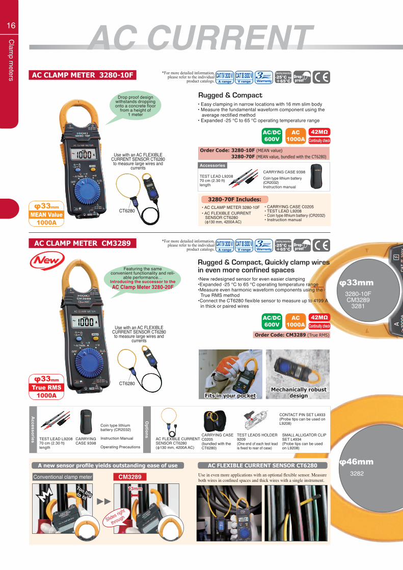
AC CLAMP METER CM3289 *For more detailed information, please refer to the individual
product catalogs.
• Easy clamping in narrow locations with 16 mm slim body• Measure the fundamental waveform component using the average rectified method• Expanded -25 °C to 65 °C operating temperature range
•New redesigned sensor for even easier clamping •Expanded -25 °C to 65 °C operating temperature range•Measure even harmonic waveform components using the True RMS method•Connect the CT6280 flexible sensor to measure up to 4199 A in thick or paired wires
Drop proof design withstands dropping onto a concrete floor
from a height of 1 meter
AC/DC600V
AC1000A
42MΩContinuity check
Order Code: 3280-10F (MEAN value) 3280-70F (MEAN value, bundled with the CT6280)
AC CLAMP METER 3280-10F
Rugged & Compact
TEST LEAD L920870 cm (2.30 ft) length
CARRYING CASE 9398Coin type lithium battery (CR2032)Instruction manual
Accessories
3280-70F Includes:
• AC FLEXIBLE CURRENT SENSOR CT6280 (φ130 mm, 4200A AC)
• AC CLAMP METER 3280-10F • CARRYING CASE C0205 • TEST LEAD L9208• Coin type lithium battery (CR2032)• Instruction manual
φ33mm
1000AMEAN Value
*For more detailed information, please refer to the individual
product catalogs.
Use with an AC FLEXIBLE CURRENT SENSOR CT6280 to measure large wires and
currents
CT6280
Use with an AC FLEXIBLE CURRENT SENSOR CT6280 to measure large wires and
currents
CT6280
φ33mm3280-10FCM3289
3281
Rugged & Compact, Quickly clamp wires in even more confined spacesFeaturing the same
convenient functionality and reli-able performance…
Introducing the successor to theAC Clamp Meter 3280-20F
φ33mm
1000ATrue RMS
AC/DC600V
AC1000A
42MΩContinuity check
Order Code: CM3289 (True RMS)
A new sensor profile yields outstanding ease of use AC FLEXIBLE CURRENT SENSOR CT6280
CM3289Conventional clamp meter
Slides right
through
13mmToo big to fit
Use in even more applications with an optional flexible sensor. Measure both wires in confined spaces and thick wires with a single instrument.
Accessories
Options
TEST LEAD L920870 cm (2.30 ft) length
CARRYING CASE 9398
Coin type lithium battery (CR2032)
Instruction Manual
Operating Precautions
CARRYING CASE C0205(bundled with the CT6280)
AC FLEXIBLE CURRENT SENSOR CT6280(φ130 mm, 4200A AC)
CONTACT PIN SET L4933 (Probe tips can be used on L9208)
SMALL ALLIGATOR CLIP SET L4934(Probe tips can be used on L9208)
TEST LEADS HOLDER 9209(One end of each test lead is fixed to rear of case)
Mechanically robust designFits in your pocket
AC CURRENT
17
Clam
p meters
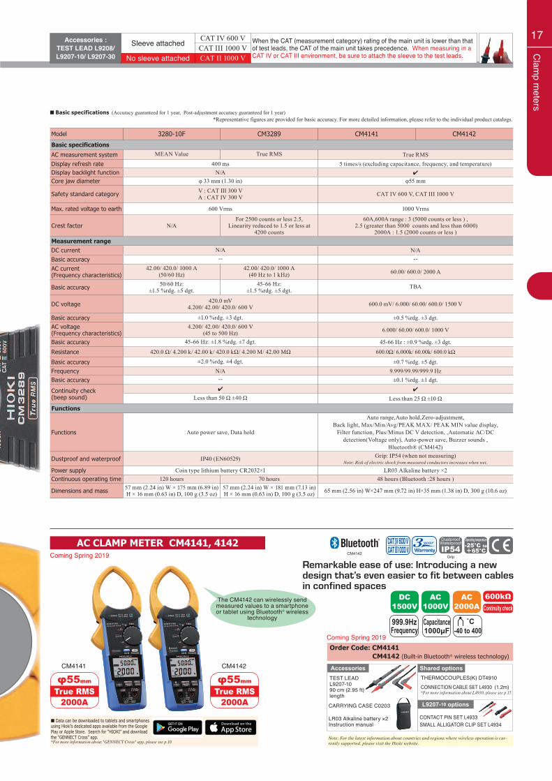
Order Code: CM4141 CM4142 (Built-in Bluetooth® wireless technology)
AC CLAMP METER CM4141, 4142
φ55mm
2000ATrue RMS
CM4141
φ55mm
2000ATrue RMS
CM4142
*Representative figures are provided for basic accuracy. For more detailed information, please refer to the individual product catalogs.
Model 3280-10F CM3289 CM4141 CM4142
Basic specifications
AC measurement system MEAN Value True RMS True RMSDisplay refresh rate 400 ms 5 times/s (excluding capacitance, frequency, and temperature) Display backlight function N/A 4
Core jaw diameter φ 33 mm (1.30 in) φ55 mm
Safety standard category V : CAT III 300 VA : CAT IV 300 V CAT IV 600 V, CAT III 1000 V
Max. rated voltage to earth 600 Vrms 1000 Vrms
Crest factor N/AFor 2500 counts or less 2.5,
Linearity reduced to 1.5 or less at 4200 counts
60A,600A range : 3 (5000 counts or less ) , 2.5 (greater than 5000 counts and less than 6000)
2000A : 1.5 (2000 counts or less )Measurement rangeDC current N/A N/ABasic accuracy -- --
AC current(Frequency characteristics)
42.00/ 420.0/ 1000 A(50/60 Hz)
42.00/ 420.0/ 1000 A(40 Hz to 1 kHz) 60.00/ 600.0/ 2000 A
Basic accuracy 50/60 Hz: ±1.5 %rdg. ±5 dgt.
45-66 Hz: ±1.5 %rdg. ±5 dgt.
TBA
DC voltage 420.0 mV4.200/ 42.00/ 420.0/ 600 V 600.0 mV/ 6.000/ 60.00/ 600.0/ 1500 V
Basic accuracy ±1.0 %rdg. ±3 dgt. ±0.5 %rdg. ±3 dgt.AC voltage(Frequency characteristics)
4.200/ 42.00/ 420.0/ 600 V(45 to 500 Hz) 6.000/ 60.00/ 600.0/ 1000 V
Basic accuracy 45-66 Hz: ±1.8 %rdg. ±7 dgt. 45-66 Hz : ±0.9 %rdg. ±3 dgt.
Resistance 420.0 Ω/ 4.200 k/ 42.00 k/ 420.0 kΩ/ 4.200 M/ 42.00 MΩ 600.0Ω/ 6.000k/ 60.00k/ 600.0 kΩ
Basic accuracy ±2.0 %rdg. ±4 dgt. ±0.7 %rdg. ±5 dgt.Frequency N/A 9.999/99.99/999.9 HzBasic accuracy -- ±0.1 %rdg. ±1 dgt.
Continuity check(beep sound)
4 4
Less than 50 Ω ±40 Ω Less than 25 Ω ±10 Ω
Functions
Functions Auto power save, Data hold
Auto range,Auto hold,Zero-adjustment,Back light, Max/Min/Avg/PEAK MAX/ PEAK MIN value display,
Filter function, Plus/Minus DC V detection, ,Automatic AC/DC detection(Voltage only), Auto-power save, Buzzer sounds ,
Bluetooth® (CM4142)
Dustproof and waterproof IP40 (EN60529) Grip: IP54 (when not measuring)Note: Risk of electric shock from measured conductors increases when wet.
Power supply Coin type lithium battery CR2032×1 LR03 Alkaline battery ×2Continuous operating time 120 hours 70 hours 48 hours (Bluetooth :28 hours )
Dimensions and mass 57 mm (2.24 in) W × 175 mm (6.89 in) H × 16 mm (0.63 in) D, 100 g (3.5 oz)
57 mm (2.24 in) W × 181 mm (7.13 in) H × 16 mm (0.63 in) D, 100 g (3.5 oz) 65 mm (2.56 in) W×247 mm (9.72 in) H×35 mm (1.38 in) D, 300 g (10.6 oz)
■ Basic specifications (Accuracy guaranteed for 1 year, Post-adjustment accuracy guaranteed for 1 year)
Accessories :TEST LEAD L9208/ L9207-10/ L9207-30
Sleeve attached CAT IV 600 V When the CAT (measurement category) rating of the main unit is lower than that of test leads, the CAT of the main unit takes precedence. When measuring in a CAT IV or CAT III environment, be sure to attach the sleeve to the test leads.
CAT III 1000 VNo sleeve attached CAT II 1000 V
Coming Spring 2019
Coming Spring 2019
The CM4142 can wirelessly send measured values to a smartphone or tablet using Bluetooth® wireless
technology
GripCM4142
Note: For the latest information about countries and regions where wireless operation is cur-rently supported, please visit the Hioki website.
AC1000V
DC1500V
AC2000A
600kΩContinuity check
999.9HzFrequency
Capacitance1000μF
˚C-40 to 400
Shared optionsTHERMOCOUPLES(K) DT4910CONNECTION CABLE SET L4930 (1.2m)*For more information about L4930, please see p.15
TEST LEAD L9207-1090 cm (2.95 ft) length
CARRYING CASE C0203
LR03 Alkaline battery ×2Instruction manual
L9207-10 options
CONTACT PIN SET L4933SMALL ALLIGATOR CLIP SET L4934
Accessories
■ Data can be downloaded to tablets and smartphonesusing Hioki’s dedicated apps available from the GooglePlay or Apple Store. Search for “HIOKI” and downloadthe “GENNECT Cross” app.*For more information about "GENNECT Cross" app, please see p.10
Remarkable ease of use: Introducing a new design that’s even easier to fit between cables in confined spaces
18
Clam
p meters
φ 35mm32873288
3288-20
φ 55mm3285
CM4373CM4374
φ 34mmCM4375CM4376
φ 33mm3284
CM4371CM4372
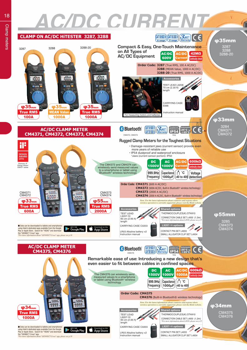
CLAMP ON AC/DC HiTESTER 3287, 3288
Compact & Easy, One-Touch Maintenance on All Types ofAC/DC Equipment
φ35mm
100ATrue RMS
3287
φ35mm
1000AMEAN Value
3288 3288-20
φ35mm
1000ATrue RMS
TEST LEAD L920870 cm (2.30 ft) length
CARRYING CASE 9398
For measuring motors and batteries
Accessories
AC/DC600V
AC/DCCurrent
42MΩContinuity check
Instruction manual
AC/DC CURRENTOrder Code: 3287 (True RMS, 100 A AC/DC) 3288 (MEAN Value, 1000 A AC/DC) 3288-20 (True RMS, 1000 A AC/DC)
CM4373CM4374
Rugged Clamp Meters for the Toughest Situations• Damage-resistant jaws (current sensor) provide even more years of reliable use• IP54 dustproof and waterproof enclosure *Jaws (current sensor portion): IP50
The CM4372 and CM4374 can wirelessly send measured values to a smartphone or tablet using Bluetooth® wireless technology
The CM4376 can wirelessly send measured values to a smartphone or tablet using Bluetooth® wireless
technology
AC/DC CLAMP METERCM4371, CM4372, CM4373, CM4374
AC1000V
DC1500V
AC/DCCurrent
600kΩContinuity check
999.9HzFrequency
Capacitance1000μF
Voltagedetection
˚C-40 to 400
AC1000V
DC1500V
AC/DC1000A
600kΩContinuity check
999.9HzFrequency
Capacitance1000μF
˚C-40 to 400
CM4371CM4372
φ33mm
600ATrue RMS
φ55mm
2000ATrue RMS
φ34mm
1000ATrue RMS
Order Code: CM4371 (600 A AC/DC) CM4372 (600A AC/DC, Built-in Bluetooth® wireless technology) CM4373 (2000 A AC/DC) CM4374 (2000 A AC/DC, Built-in Bluetooth® wireless technology)
Order Code: CM4375 CM4376 (Built-in Bluetooth® wireless technology)
Shared optionsTHERMOCOUPLES(K) DT4910CONNECTION CABLE SET L4930 (1.2m)*For more information about L4930, please see p.15
TEST LEAD L9207-1090 cm (2.95 ft) length
CARRYING CASE C0203
LR03 Alkaline battery ×2Instruction manual
L9207-10 options
CONTACT PIN SET L4933SMALL ALLIGATOR CLIP SET L4934
Accessories
GripCM4372, CM4374
Germany iF Design AwardCM4371 series
■ Data can be downloaded to tablets and smartphonesusing Hioki’s dedicated apps available from the GooglePlay or Apple Store. Search for “HIOKI” and downloadthe “GENNECT Cross” app.*For more information about "GENNECT Cross" app, please see p.10
■ Data can be downloaded to tablets and smartphonesusing Hioki’s dedicated apps available from the GooglePlay or Apple Store. Search for “HIOKI” and downloadthe “GENNECT Cross” app.*For more information about "GENNECT Cross" app, please see p.10
GripCM4376
Note: For the latest information about countries and regions where wireless operation is currently supported, please visit the Hioki website.
Note: For the latest information about countries and regions where wireless operation is currently supported, please visit the Hioki website.
AC/DC CLAMP METERCM4375, CM4376
Remarkable ease of use: Introducing a new design that’s even easier to fit between cables in confined spaces
19
Clam
p meters
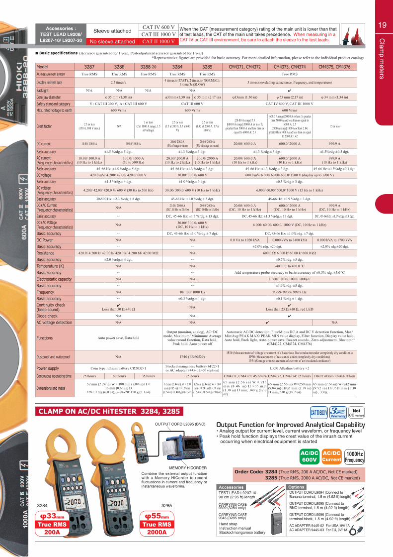
*Representative figures are provided for basic accuracy. For more detailed information, please refer to the individual product catalogs.■ Basic specifications (Accuracy guaranteed for 1 year, Post-adjustment accuracy guaranteed for 1 year)
Output Function for Improved Analytical Capability• Analog output for current level, current waveform, or frequency level• Peak hold function displays the crest value of the inrush current occurring when electrical equipment is started
φ55mm
2000ATrue RMS
3285
CLAMP ON AC/DC HiTESTER 3284, 3285
AC/DC600V
AC/DCCurrent
1000HzFrequency
AC ADAPTER 9445-02 For USA, 9V/ 1AAC ADAPTER 9445-03 For EU, 9V/ 1A
OUTPUT CORD L9094 (Connect to Banana terminal, 1.5 m (4.92 ft) length)
OUTPUT CORD L9095 (Connect to BNC terminal, 1.5 m (4.92 ft) length)
OUTPUT CORD L9096 (Connect to terminal block, 1.5 m (4.92 ft) length)
TEST LEAD L9207-1090 cm (2.95 ft) length
CARRYING CASE 9399 (3284 only)
CARRYING CASE 9345 (3285 only)Hand strapInstruction manualStacked manganese battery
Accessories Options
Order Code: 3284 (True RMS, 200 A AC/DC, Not CE marked) 3285 (True RMS, 2000 A AC/DC, Not CE marked)
φ33mm
200ATrue RMS
3284
MEMORY HiCORDERCombine the external output function with a Memory HiCorder to record fluctuations in current and frequency or instantaneous waveforms.
OUTPUT CORD L9095 (BNC)
Accessories :TEST LEAD L9208/ L9207-10/ L9207-30
Sleeve attached CAT IV 600 V When the CAT (measurement category) rating of the main unit is lower than that of test leads, the CAT of the main unit takes precedence. When measuring in a CAT IV or CAT III environment, be sure to attach the sleeve to the test leads.
CAT III 1000 VNo sleeve attached CAT II 1000 V
Model 3287 3288 3288-20 3284 3285 CM4371, CM4372 CM4373, CM4374 CM4375, CM4376AC measurement system True RMS True RMS True RMS True RMS True RMS True RMS
Display refresh rate 2.5 times/s 4 times/s (FAST), 2 times/s (NORMAL), 1 time/3s (SLOW) 5 times/s (excluding capacitance, frequency, and temperature)
Backlight N/A N/A N/A N/A 4
Core jaw diameter φ 35 mm (1.38 in) φ33mm (1.30 in) φ 55 mm (2.17 in) φ33mm (1.30 in) φ 55 mm (2.17 in) φ 34 mm (1.34 in)
Safety standard category V : CAT III 300 V, A : CAT III 600 V CAT III 600 V CAT IV 600 V, CAT III 1000 V
Max. rated voltage to earth 600 Vrms 600 Vrms 600 Vrms
Crest factor 2.5 or less (150 A, 100 V max.) N/A
3 or less(2 at 1000 A range, 1.5
at Voltage)
2.5 or less (1.5 at 200 A, 1.7 at 600
V)
2.5 or less (1.42 at 2000 A, 1.7 at
600 V)
[20.00 A range] 7.5[600.0 A range] 500.0 A or less: 3;
greater than 500.0 A and less than or equal to 600.0 A: 2.5
[600.0 A range] 500.0 A or less: 3; greater than 500.0 A and less than or equal to
600.0 A: 2.5[2000 A range] 1000 A or less: 2.84;
greater than 1000 A and less than or equal to 2000 A: 1.42
1.5 or less
DC current 10.00/ 100.0 A 100.0/ 1000 A 20.00/ 200.0 A(5% of range or more)
200.0/ 2000 A(5% of range or more) 20.00/ 600.0 A 600.0/ 2000 A 999.9 A
Basic accuracy ±1.5 %rdg.± 5 dgt. ±1.3 %rdg.± 3 dgt. ±1.3 %rdg.± 3 dgt. ±1.3%rdg.±0.3 dgt.
AC current(Frequency characteristics)
10.00/ 100.0 A(10 Hz to 1 kHz)
100.0/ 1000 A(10 to 500 Hz)
20.00/ 200.0 A(10 Hz to 2 kHz)
200.0/ 2000 A(10 Hz to 1 kHz)
20.00/ 600.0 A(10 Hz to 1 kHz)
600.0/ 2000 A(10 Hz to 1 kHz)
999.9 A(10 Hz to 1 kHz)
Basic accuracy 45-66 Hz: ±1.5 %rdg.± 5 dgt. 45-66 Hz: ±1.3 %rdg.± 3 dgt. 45-66 Hz: ±1.3 %rdg.± 3 dgt. 45-66 Hz: ±1.3%rdg.±0.3 dgt.
DC voltage 420.0 mV/ 4.200/ 42.00/ 420.0/ 600 V 30.00/ 300.0/ 600 V 600.0 mV/ 6.000/ 60.00/ 600.0/ 1500 V (display up to 1700 V)
Basic accuracy ±1.3 %rdg.± 4 dgt. ±1.0 %rdg.± 3 dgt. ±0.5 %rdg.± 3 dgt.
AC voltage(Frequency characteristics)
4.200/ 42.00/ 420.0 V/ 600 V (30 Hz to 500 Hz) 30.00/ 300.0/ 600 V (10 Hz to 1 kHz) 6.000/ 60.00/ 600.0/ 1000 V (15 Hz to 1 kHz)
Basic accuracy 30-500 Hz: ±2.3 %rdg.± 8 dgt. 45-66 Hz: ±1.0 %rdg.± 3 dgt. 45-66 Hz: ±0.9 %rdg.± 3 dgt.
DC+AC Current(Frequency characteristics)
N/A 20.00/ 200.0 A(DC, 10 Hz to 2 kHz)
200.0/ 2000 A(DC, 10 Hz to 1 kHz)
20.00/ 600.0 A(DC, 10 Hz to 1 kHz)
600.0/ 2000 A(DC, 10 Hz to 1 kHz)
999.9 A(DC, 10 Hz to 1 kHz)
Basic accuracy -- DC, 45-66 Hz: ±1.3 %rdg.± 13 dgt. DC, 45-66 Hz: ±1.3 %rdg.± 13 dgt. DC, 45-66 Hz: ±1.3%rdg.±13 dgt.
DC+AC Voltage(Frequency characteristics)
N/A 30.00/ 300.0/ 600 V(DC, 10 Hz to 1 kHz) 6.000/ 60.00/ 600.0/ 1000 V (DC, 10 Hz to 1 kHz)
Basic accuracy -- DC, 45-66 Hz: ±1.0 %rdg.± 7 dgt. DC, 45-66 Hz: ±1.0% rdg. ±7 dgt.
DC Power N/A N/A 0.0 VA to 1020 kVA 0.000 kVA to 3400 kVA 0.000 kVA to 1700 kVA
Basic accuracy -- -- ±2.0% rdg. ±20 dgt. ±2.0% rdg.±20 dgt.
Resistance 420.0/ 4.200 k/ 42.00 k/ 420.0 k/ 4.200 M/ 42.00 MΩ N/A 600.0 Ω/ 6.000 k/ 60.00 k/ 600.0 kΩ
Basic accuracy ±2.0 %rdg.± 4 dgt. -- ±0.7% rdg. ±5 dgt.
Temperature (K) N/A N/A -40.0 ˚C to 400.0 ˚C
Basic accuracy -- -- Add temperature probe accuracy to basic accuracy of ±0.5% rdg. ±3.0 ˚C
Electrostatic capacity N/A N/A 1.000/ 10.00/ 100.0/ 1000μF
Basic accuracy -- -- ±1.9% rdg. ±5 dgt.
Frequency N/A 10/ 100/ 1000 Hz 9.999/ 99.99/ 999.9 Hz
Basic accuracy -- ±0.3 %rdg.± 1 dgt. ±0.1 %rdg.± 1 dgt.
Continuity check(beep sound)
4Less than 50 Ω ±40 Ω N/A 4
Less than 25 Ω ±10 Ω, red LED
Diode check N/A N/A 4
AC voltage detection N/A N/A 4 N/A
Functions Auto power save, Data holdOutput (monitor, analog), AC+DC
mode, Maximum/ Minimum/ Average value record function, Data hold,
Peak hold, Auto power off
Automatic AC/DC detection, Plus/Minus DC A and DC V detection function, Max/Min/Avg/PEAK MAX/ PEAK MIN value display, Filter function, Display value hold, Auto hold, Back light, Auto-power save, Buzzer sounds , Zero-adjustment, Bluetooth®
(CM4372, CM4374, CM4376)
Dustproof and waterproof N/A IP40 (EN60529)IP20 (Measurement of voltage or current of a hazardous live conductorunder completely dry conditions)
IP50 (Measurement of resistance under completely dry conditions)IP54 (Storage or measurement of current of an insulated conductor)
Power supply Coin type lithium battery CR2032×1 Stacked manganese battery 6F22×1or AC adapter 9445-02/-03 (option) LR03 Alkaline battery ×2
Continuous operating time 25 hours 60 hours 35 hours 25 hours CM4371, CM4373: 45 hours/ CM4372, CM4374: 25 hours CM4375: 40 hours/ CM4376: 20 hours
Dimensions and mass57 mm (2.24 in) W × 180 mm (7.09 in) H ×
16 mm (0.63 in) D3287: 170g (6.0 oz), 3288/-20: 150 g (5.3 oz)
62 mm (2.44 in) W × 230 mm (9.05 in) H × 39 mm
(1.54 in) D, 460 g (16.2 oz)
62 mm (2.44 in) W × 260 mm (10.24 in) H × 39 mm (1.54 in) D, 540 g (19.0 oz)
65 mm (2.56 in) W × 215 m m (8.46 in) H ×35 m m (1.38 in) D mm, 340 g (12.0 oz)
65 mm (2.56 in) W×250 mm (9.84 in) H×35 mm (1.38 in) D mm, 530 g (18.7 oz)
65 mm (2.56 in) W×242 mm (9.52 in) H×35D mm (1.38 in) , 330g
20
Clam
p meters
φ40mm3283
3283-20
LEAKAGE CURRENT
φ24mm3293-50
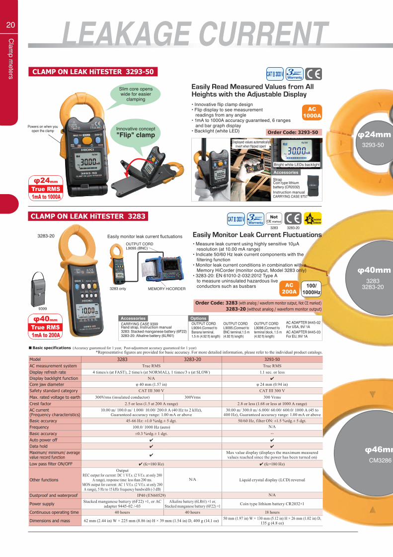
Model 3283 3283-20 3293-50AC measurement system True RMS True RMSDisplay refresh rate 4 times/s (at FAST), 2 time/s (at NORMAL), 1 times/3 s (at SLOW) 1.1 sec. or lessDisplay backlight function N/A 4
Core jaw diameter φ 40 mm (1.57 in) φ 24 mm (0.94 in)Safety standard category CAT III 300 V CAT III 300 VMax. rated voltage to earth 300Vrms (insulated conductor) 300Vrms 300 VrmsCrest factor 2.5 or less (1.5 at 200 A range) 2.8 or less (1.68 or less at 1000 A range)AC current (Frequency characteristics)
10.00 m/ 100.0 m/ 1.000/ 10.00/ 200.0 A (40 Hz to 2 kHz),Guaranteed accuracy range: 1.00 mA or above
30.00 m/ 300.0 m/ 6.000/ 60.00/ 600.0/ 1000 A (45 to 400 Hz), Guaranteed accuracy range: 1.00 mA or above
Basic accuracy 45-66 Hz: ±1.0 %rdg.± 5 dgt. 50/60 Hz, filter ON: ±1.5 %rdg.± 5 dgt.Frequency 100.0/ 1000 Hz (auto) N/A
Basic accuracy ±0.3 %rdg.± 1 dgt. --Auto power off 4 4
Data hold 4 4
Maximum/ minimum/ average value record function 4
Max value display (displays the maximum measured values reached since the power has been turned on)
Low pass filter ON/OFF 4 (fc=180 Hz) 4 (fc=180 Hz)
Other functions
OutputREC output for current: DC 1 V/f.s. (2 V/f.s. at only 200
A range), response time: less than 200 ms.MON output for current: AC 1 V/f.s. (2 V/f.s. at only 200 A range), 5 Hz to 15 kHz frequency bandwidth (-3 dB)
N/A Liquid crystal display (LCD) reversal
Dustproof and waterproof IP40 (EN60529) N/A
Power supply Stacked manganese battery (6F22) ×1, or AC adapter 9445-02 /-03
Alkaline battery (6LR61) ×1 or, Stacked manganese battery (6F22) ×1 Coin type lithium battery CR2032×1
Continuous operating time 40 hours 40 hours 18 hours
Dimensions and mass 62 mm (2.44 in) W × 225 mm (8.86 in) H × 39 mm (1.54 in) D, 400 g (14.1 oz) 50 mm (1.97 in) W × 130 mm (5.12 in) H × 26 mm (1.02 in) D, 135 g (4.8 oz)
*Representative figures are provided for basic accuracy. For more detailed information, please refer to the individual product catalogs.■ Basic specifications (Accuracy guaranteed for 1 year, Post-adjustment accuracy guaranteed for 1 year)
Easily Read Measured Values from AllHeights with the Adjustable Display• Innovative flip clamp design• Flip display to see measurement readings from any angle• 1mA to 1000A accuracy guaranteed, 6 ranges and bar graph display• Backlight (white LED)
AC1000A
CLAMP ON LEAK HiTESTER 3293-50
Displayed values automatically invert when flipped open!
StrapCoin type lithiumbattery (CR2032)Instruction manualCARRYING CASE 9757
Bright white LEDs backlight
Powers on when you open the clamp
Accessories
Order Code: 3293-50
CLAMP ON LEAK HiTESTER 3283
Easily Monitor Leak Current Fluctuations• Measure leak current using highly sensitive 10μA resolution (at 10.00 mA range)• Indicate 50/60 Hz leak current components with the filtering function• Monitor leak current conditions in combination with a Memory HiCorder (monitor output, Model 3283 only)• 3283-20: EN 61010-2-032:2012 Type A to measure uninsulated hazardous live conductors such as busbars
3283-20
Order Code: 3283 (with analog / waveform monitor output, Not CE marked) 3283-20 (without analog / waveform monitor output)
3283-203283
φ24mm
1mA to 1000ATrue RMS
AC 200A
100/1000Hz
CARRYING CASE 9399Hand strap, Instruction manual 3283: Stacked manganese battery (6F22) 3283-20: Alkaline battery (6LR61)
AccessoriesAC ADAPTER 9445-02For USA, 9V/ 1AAC ADAPTER 9445-03For EU, 9V/ 1A
OUTPUT CORD L9094 (Connect to Banana terminal,1.5 m (4.92 ft) length)
OUTPUT CORD L9095 (Connect to BNC terminal,1.5 m (4.92 ft) length)
OUTPUT CORD L9096 (Connect to terminal block, 1.5 m (4.92 ft) length)
Optionsφ40mm
1mA to 200ATrue RMS
Easily monitor leak current fluctuations
Innovative concept"Flip" clamp
Slim core opens wide for easier
clamping
3283 only
OUTPUT CORD L9095 (BNC)
MEMORY HiCORDER
9399
φ46mmCM3286
21
Clam
p meters
φ46mmCM3286
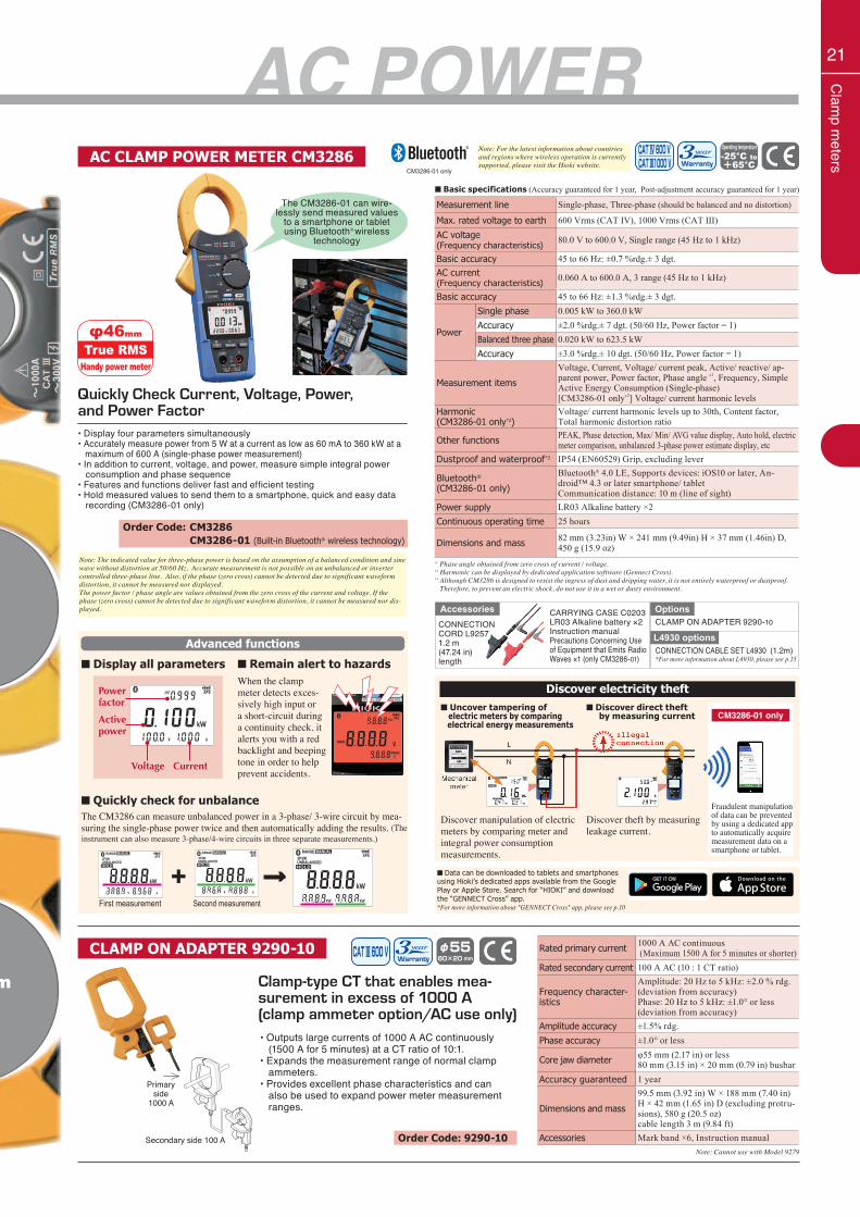
AC POWERAC CLAMP POWER METER CM3286
φ46mm
Handy power meterTrue RMS
Discover electricity theft
Clamp-type CT that enables mea-surement in excess of 1000 A (clamp ammeter option/AC use only)
CLAMP ON ADAPTER 9290-10
• Outputs large currents of 1000 A AC continuously (1500 A for 5 minutes) at a CT ratio of 10:1.• Expands the measurement range of normal clamp ammeters.• Provides excellent phase characteristics and can also be used to expand power meter measurement ranges.
Primary side
1000 A
Secondary side 100 A
Rated primary current 1000 A AC continuous (Maximum 1500 A for 5 minutes or shorter)
Rated secondary current 100 A AC (10 : 1 CT ratio)
Frequency character-istics
Amplitude: 20 Hz to 5 kHz: ±2.0 % rdg. (deviation from accuracy)Phase: 20 Hz to 5 kHz: ±1.0° or less (deviation from accuracy)
Amplitude accuracy ±1.5% rdg.Phase accuracy ±1.0° or less
Core jaw diameter φ55 mm (2.17 in) or less80 mm (3.15 in) × 20 mm (0.79 in) busbar
Accuracy guaranteed 1 year
Dimensions and mass
99.5 mm (3.92 in) W × 188 mm (7.40 in) H × 42 mm (1.65 in) D (excluding protru-sions), 580 g (20.5 oz)cable length 3 m (9.84 ft)
Accessories Mark band ×6, Instruction manualNote: Cannot use with Model 9279
Order Code: 9290-10
■ Basic specifications (Accuracy guaranteed for 1 year, Post-adjustment accuracy guaranteed for 1 year)
Note: For the latest information about countries and regions where wireless operation is currently supported, please visit the Hioki website.
CM3286-01 only
Measurement line Single-phase, Three-phase (should be balanced and no distortion)
Max. rated voltage to earth 600 Vrms (CAT IV), 1000 Vrms (CAT III)AC voltage(Frequency characteristics)
80.0 V to 600.0 V, Single range (45 Hz to 1 kHz)
Basic accuracy 45 to 66 Hz: ±0.7 %rdg.± 3 dgt.AC current(Frequency characteristics)
0.060 A to 600.0 A, 3 range (45 Hz to 1 kHz)
Basic accuracy 45 to 66 Hz: ±1.3 %rdg.± 3 dgt.
Power
Single phase 0.005 kW to 360.0 kWAccuracy ±2.0 %rdg.± 7 dgt. (50/60 Hz, Power factor = 1)Balanced three phase 0.020 kW to 623.5 kWAccuracy ±3.0 %rdg.± 10 dgt. (50/60 Hz, Power factor = 1)
Measurement items
Voltage, Current, Voltage/ current peak, Active/ reactive/ ap-parent power, Power factor, Phase angle *1, Frequency, Simple Active Energy Consumption (Single-phase)[CM3286-01 only*2] Voltage/ current harmonic levels
Harmonic (CM3286-01 only*2)
Voltage/ current harmonic levels up to 30th, Content factor, Total harmonic distortion ratio
Other functions PEAK, Phase detection, Max/ Min/ AVG value display, Auto hold, electric meter comparison, unbalanced 3-phase power estimate display, etc
Dustproof and waterproof*3 IP54 (EN60529) Grip, excluding lever
Bluetooth®
(CM3286-01 only)
Bluetooth® 4.0 LE, Supports devices: iOS10 or later, An-droid™ 4.3 or later smartphone/ tabletCommunication distance: 10 m (line of sight)
Power supply LR03 Alkaline battery ×2Continuous operating time 25 hours
Dimensions and mass 82 mm (3.23in) W × 241 mm (9.49in) H × 37 mm (1.46in) D, 450 g (15.9 oz)
Quickly Check Current, Voltage, Power, and Power Factor• Display four parameters simultaneously• Accurately measure power from 5 W at a current as low as 60 mA to 360 kW at a maximum of 600 A (single-phase power measurement)• In addition to current, voltage, and power, measure simple integral power consumption and phase sequence• Features and functions deliver fast and efficient testing• Hold measured values to send them to a smartphone, quick and easy data recording (CM3286-01 only)
Order Code: CM3286 CM3286-01 (Built-in Bluetooth® wireless technology)
■ Data can be downloaded to tablets and smartphones using Hioki’s dedicated apps available from the Google Play or Apple Store. Search for “HIOKI” and download the “GENNECT Cross” app.*For more information about "GENNECT Cross" app, please see p.10
*1 Phase angle obtained from zero cross of current / voltage.*2 Harmonic can be displayed by dedicated application software (Gennect Cross).*3 Although CM3286 is designed to resist the ingress of dust and dripping water, it is not entirely waterproof or dustproof. Therefore, to prevent an electric shock, do not use it in a wet or dusty environment.
OptionsCLAMP ON ADAPTER 9290-10
CONNECTION CABLE SET L4930 (1.2m)*For more information about L4930, please see p.15
CONNECTION CORD L92571.2 m(47.24 in)length
CARRYING CASE C0203LR03 Alkaline battery ×2Instruction manualPrecautions Concerning Use of Equipment that Emits Radio Waves ×1 (only CM3286-01)
L4930 options
Accessories
■ Uncover tampering of electric meters by comparing electrical energy measurements
■ Discover direct theft by measuring current
Advanced functions
■ Display all parameters ■ Remain alert to hazardsWhen the clamp meter detects exces-sively high input or a short-circuit during a continuity check, it alerts you with a red backlight and beeping tone in order to help prevent accidents.
Power factor
Activepower
Voltage Current
■ Quickly check for unbalanceThe CM3286 can measure unbalanced power in a 3-phase/ 3-wire circuit by mea-suring the single-phase power twice and then automatically adding the results. (The instrument can also measure 3-phase/4-wire circuits in three separate measurements.)
First measurement
+ →Second measurement
The CM3286-01 can wire-lessly send measured values
to a smartphone or tablet using Bluetooth® wireless
technology
Discover manipulation of electric meters by comparing meter and integral power consumption measurements.
Discover theft by measuring leakage current.
CM3286-01 only
Fraudulent manipulation of data can be prevented by using a dedicated app to automatically acquire measurement data on a smartphone or tablet.
Note: The indicated value for three-phase power is based on the assumption of a balanced condition and sine wave without distortion at 50/60 Hz. Accurate measurement is not possible on an unbalanced or inverter controlled three-phase line. Also, if the phase (zero cross) cannot be detected due to significant waveform distortion, it cannot be measured nor displayed.The power factor / phase angle are values obtained from the zero cross of the current and voltage. If the phase (zero cross) cannot be detected due to significant waveform distortion, it cannot be measured nor dis-played.
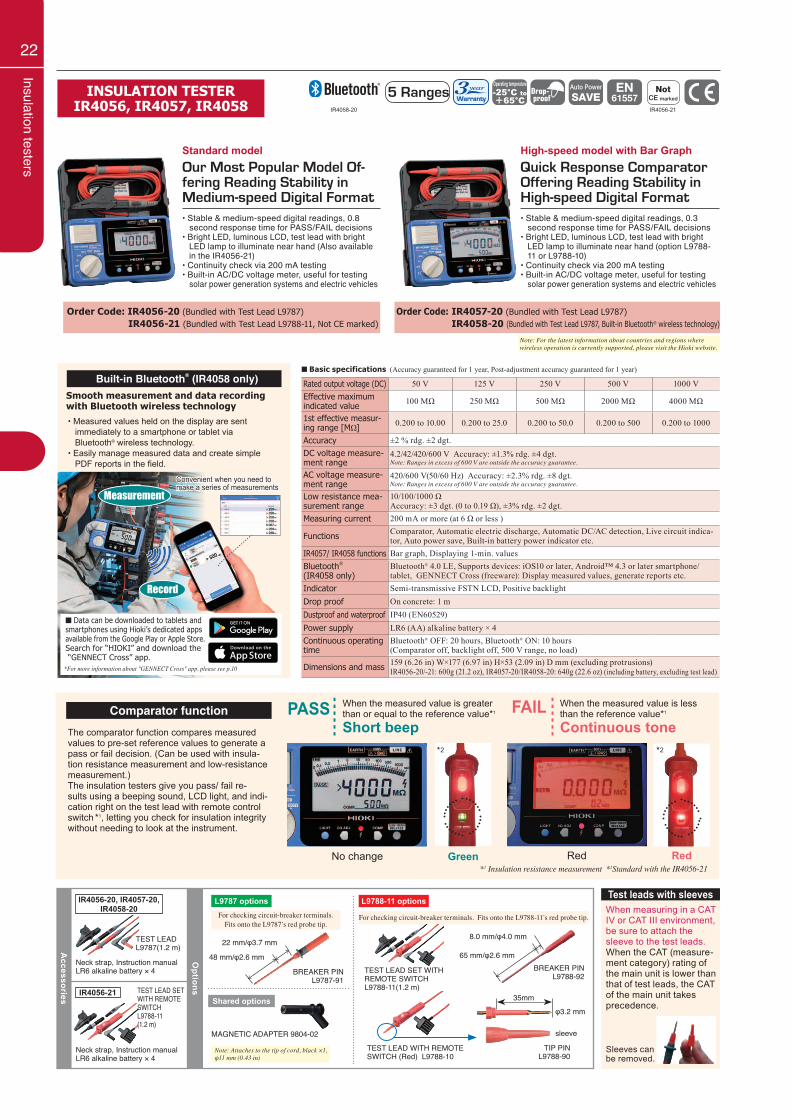
22
Insulation testers
INSULATION TESTERIR4056, IR4057, IR4058
The comparator function compares measured values to pre-set reference values to generate a pass or fail decision. (Can be used with insula-tion resistance measurement and low-resistance measurement.)The insulation testers give you pass/ fail re-sults using a beeping sound, LCD light, and indi-cation right on the test lead with remote control switch *1, letting you check for insulation integrity without needing to look at the instrument.
Comparator function PASS When the measured value is greater than or equal to the reference value*1
Short beep
No change Green
*2
*1 Insulation resistance measurement *2Standard with the IR4056-21
FAIL When the measured value is less than the reference value*1
Continuous tone
Red Red
*2
Rated output voltage (DC) 50 V 125 V 250 V 500 V 1000 V Effective maximum indicated value 100 MΩ 250 MΩ 500 MΩ 2000 MΩ 4000 MΩ
1st effective measur-ing range [MΩ] 0.200 to 10.00 0.200 to 25.0 0.200 to 50.0 0.200 to 500 0.200 to 1000
Accuracy ±2 % rdg. ±2 dgt.DC voltage measure-ment range
4.2/42/420/600 V Accuracy: ±1.3% rdg. ±4 dgt.Note: Ranges in excess of 600 V are outside the accuracy guarantee.
AC voltage measure-ment range
420/600 V(50/60 Hz) Accuracy: ±2.3% rdg. ±8 dgt. Note: Ranges in excess of 600 V are outside the accuracy guarantee.
Low resistance mea-surement range
10/100/1000 ΩAccuracy: ±3 dgt. (0 to 0.19 Ω), ±3% rdg. ±2 dgt.
Measuring current 200 mA or more (at 6 Ω or less )
Functions Comparator, Automatic electric discharge, Automatic DC/AC detection, Live circuit indica-tor, Auto power save, Built-in battery power indicator etc.
IR4057/ IR4058 functions Bar graph, Displaying 1-min. valuesBluetooth®
(IR4058 only)Bluetooth® 4.0 LE, Supports devices: iOS10 or later, Android™ 4.3 or later smartphone/ tablet, GENNECT Cross (freeware): Display measured values, generate reports etc.
Indicator Semi-transmissive FSTN LCD, Positive backlightDrop proof On concrete: 1 mDustproof and waterproof IP40 (EN60529)Power supply LR6 (AA) alkaline battery × 4Continuous operating time
Bluetooth® OFF: 20 hours, Bluetooth® ON: 10 hours(Comparator off, backlight off, 500 V range, no load)
Dimensions and mass 159 (6.26 in) W×177 (6.97 in) H×53 (2.09 in) D mm (excluding protrusions)IR4056-20/-21: 600g (21.2 oz), IR4057-20/IR4058-20: 640g (22.6 oz) (including battery, excluding test lead)
■ Basic specifications (Accuracy guaranteed for 1 year, Post-adjustment accuracy guaranteed for 1 year)
Accessories
TEST LEAD L9787(1.2 m)
TEST LEAD SET WITH REMOTE SWITCHL9788-11(1.2 m)
Neck strap, Instruction manualLR6 alkaline battery × 4
Neck strap, Instruction manualLR6 alkaline battery × 4
Options
L9787 options
Shared options
For checking circuit-breaker terminals.Fits onto the L9787’s red probe tip.
For checking circuit-breaker terminals. Fits onto the L9788-11’s red probe tip.
BREAKER PINL9787-91
BREAKER PINL9788-92
MAGNETIC ADAPTER 9804-02
L9788-11 options
TEST LEAD WITH REMOTE SWITCH (Red) L9788-10
35mm
TIP PINL9788-90
φ3.2 mm
sleeve
65 mm/φ2.6 mm
8.0 mm/φ4.0 mm
48 mm/φ2.6 mm
22 mm/φ3.7 mm
TEST LEAD SET WITH REMOTE SWITCHL9788-11(1.2 m)
Note: Attaches to the tip of cord, black ×1, φ11 mm (0.43 in)
When measuring in a CAT IV or CAT III environment, be sure to attach the sleeve to the test leads.When the CAT (measure-ment category) rating of the main unit is lower than that of test leads, the CAT of the main unit takes precedence.
Test leads with sleeves
Sleeves can be removed.
Our Most Popular Model Of-fering Reading Stability in Medium-speed Digital Format• Stable & medium-speed digital readings, 0.8 second response time for PASS/FAIL decisions• Bright LED, luminous LCD, test lead with bright LED lamp to illuminate near hand (Also available in the IR4056-21)• Continuity check via 200 mA testing• Built-in AC/DC voltage meter, useful for testing solar power generation systems and electric vehicles
Order Code: IR4056-20 (Bundled with Test Lead L9787) IR4056-21 (Bundled with Test Lead L9788-11, Not CE marked)
Order Code: IR4057-20 (Bundled with Test Lead L9787) IR4058-20 (Bundled with Test Lead L9787, Built-in Bluetooth® wireless technology)
Quick Response Comparator Offering Reading Stability in High-speed Digital Format
5 RangesIR4058-20
Note: For the latest information about countries and regions where wireless operation is currently supported, please visit the Hioki website.
IR4056-21
High-speed model with Bar GraphStandard model
• Stable & medium-speed digital readings, 0.3 second response time for PASS/FAIL decisions• Bright LED, luminous LCD, test lead with bright LED lamp to illuminate near hand (option L9788- 11 or L9788-10)• Continuity check via 200 mA testing• Built-in AC/DC voltage meter, useful for testing solar power generation systems and electric vehicles
Smooth measurement and data recording with Bluetooth wireless technology• Measured values held on the display are sent immediately to a smartphone or tablet via Bluetooth® wireless technology.• Easily manage measured data and create simple PDF reports in the field.
Convenient when you need to make a series of measurements
Measurement
Record
■ Data can be downloaded to tablets andsmartphones using Hioki’s dedicated appsavailable from the Google Play or Apple Store.Search for “HIOKI” and download the “GENNECT Cross” app.
*For more information about "GENNECT Cross" app, please see p.10
IR4056-20, IR4057-20, IR4058-20
IR4056-21
Built-in Bluetooth® (IR4058 only)
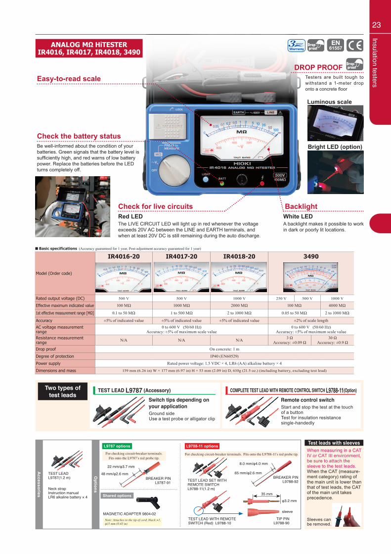
23Insulation testers
ANALOG MΩ HiTESTERIR4016, IR4017, IR4018, 3490
Luminous scale
Bright LED (option)
DROP PROOFTesters are built tough to withstand a 1-meter drop onto a concrete floor
Easy-to-read scale
Check the battery status
Check for live circuits BacklightRed LEDThe LIVE CIRCUIT LED will light up in red whenever the voltage exceeds 20V AC between the LINE and EARTH terminals, and when at least 20V DC is still remaining during the auto discharge.
Be well-informed about the condition of your batteries. Green signals that the battery level is sufficiently high, and red warns of low battery power. Replace the batteries before the LED turns completely off.
White LEDA backlight makes it possible to work in dark or poorly lit locations.
Two types oftest leads
When measuring in a CAT IV or CAT III environment, be sure to attach the sleeve to the test leads.When the CAT (measure-ment category) rating of the main unit is lower than that of test leads, the CAT of the main unit takes precedence.
Test leads with sleeves
Sleeves can be removed.
Ground sideUse a test probe or alligator clip
Start and stop the test at the touch of a buttonTest for insulation resistance single-handedly
TEST LEAD L9787 (Accessory) COMPLETE TEST LEAD WITH REMOTE CONTROL SWITCH L9788-11(Option)Switch tips depending on your application
Remote control switch
Accessories
TEST LEAD L9787(1.2 m)
Neck strapInstruction manualLR6 alkaline battery × 4
Options
L9787 options
Shared options
BREAKER PINL9787-91
MAGNETIC ADAPTER 9804-02
L9788-11 options
TEST LEAD WITH REMOTE SWITCH (Red) L9788-10
35 mm
TIP PINL9788-90
φ3.2 mm
sleeve
65 mm/φ2.6 mm
8.0 mm/φ4.0 mm
48 mm/φ2.6 mm
22 mm/φ3.7 mm
TEST LEAD SET WITH REMOTE SWITCHL9788-11(1.2 m)
For checking circuit-breaker terminals.Fits onto the L9787’s red probe tip.
For checking circuit-breaker terminals. Fits onto the L9788-11’s red probe tip.
Model (Order code)
IR4016-20 IR4017-20 IR4018-20 3490
Rated output voltage (DC) 500 V 500 V 1000 V 250 V 500 V 1000 V
Effective maximum indicated value 100 MΩ 1000 MΩ 2000 MΩ 100 MΩ 4000 MΩ
1st effective measurement range [MΩ] 0.1 to 50 MΩ 1 to 500 MΩ 2 to 1000 MΩ 0.05 to 50 MΩ 2 to 1000 MΩ
Accuracy ±5% of indicated value ±5% of indicated value ±5% of indicated value ±2% of scale lengthAC voltage measurement range
0 to 600 V (50/60 Hz)Accuracy: ±5% of maximum scale value
0 to 600 V (50/60 Hz)Accuracy: ±5% of maximum scale value
Resistance measurement range N/A N/A N/A 3 Ω
Accuracy: ±0.09 Ω30 Ω
Accuracy: ±0.9 ΩDrop proof On concrete: 1 m
Degree of protection IP40 (EN60529)
Power supply Rated power voltage: 1.5 VDC × 4, LR6 (AA) alkaline battery × 4
Dimensions and mass 159 mm (6.26 in) W × 177 mm (6.97 in) H × 53 mm (2.09 in) D, 610g (21.5 oz.) (including battery, excluding test lead)
■ Basic specifications (Accuracy guaranteed for 1 year, Post-adjustment accuracy guaranteed for 1 year)
Note: Attaches to the tip of cord, black ×1, φ11 mm (0.43 in)
BREAKER PINL9788-92
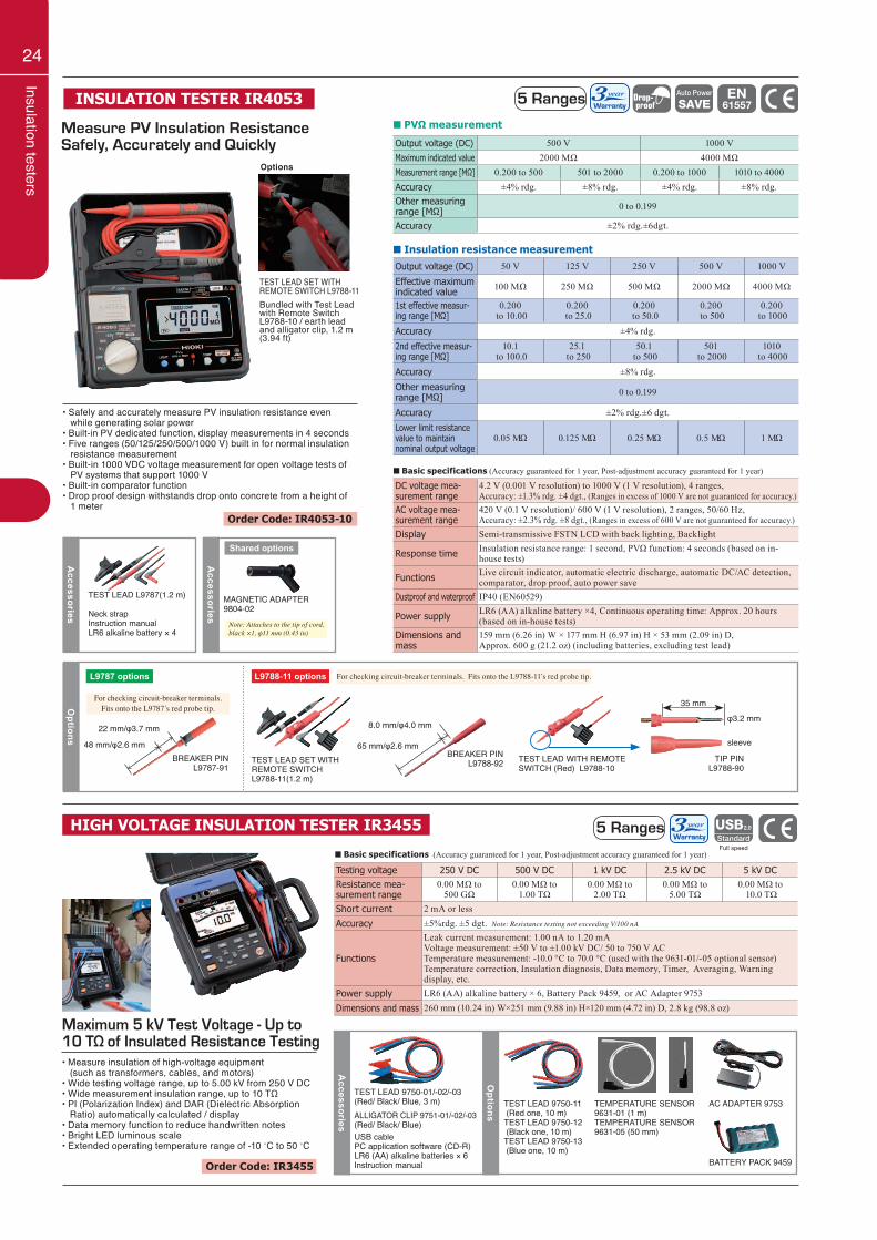
24
Insulation testers
■ Insulation resistance measurement
Output voltage (DC) 50 V 125 V 250 V 500 V 1000 V
Effective maximum indicated value 100 MΩ 250 MΩ 500 MΩ 2000 MΩ 4000 MΩ
1st effective measur-ing range [MΩ]
0.200 to 10.00
0.200 to 25.0
0.200 to 50.0
0.200 to 500
0.200 to 1000
Accuracy ±4% rdg.
2nd effective measur-ing range [MΩ]
10.1 to 100.0
25.1 to 250
50.1 to 500
501 to 2000
1010 to 4000
Accuracy ±8% rdg.
Other measuring range [MΩ] 0 to 0.199
Accuracy ±2% rdg.±6 dgt.
Lower limit resistance value to maintainnominal output voltage
0.05 MΩ 0.125 MΩ 0.25 MΩ 0.5 MΩ 1 MΩ
Output voltage (DC) 500 V 1000 VMaximum indicated value 2000 MΩ 4000 MΩMeasurement range [MΩ] 0.200 to 500 501 to 2000 0.200 to 1000 1010 to 4000Accuracy ±4% rdg. ±8% rdg. ±4% rdg. ±8% rdg.Other measuringrange [MΩ] 0 to 0.199
Accuracy ±2% rdg.±6dgt.
■ PVΩ measurement
Accessories
TEST LEAD L9787(1.2 m)
Measure PV Insulation Resistance Safely, Accurately and Quickly
INSULATION TESTER IR4053 5 Ranges
• Safely and accurately measure PV insulation resistance even while generating solar power• Built-in PV dedicated function, display measurements in 4 seconds• Five ranges (50/125/250/500/1000 V) built in for normal insulation resistance measurement• Built-in 1000 VDC voltage measurement for open voltage tests of PV systems that support 1000 V• Built-in comparator function• Drop proof design withstands drop onto concrete from a height of 1 meter
Order Code: IR4053-10
Neck strapInstruction manualLR6 alkaline battery × 4
Options
L9787 options
For checking circuit-breaker terminals.Fits onto the L9787’s red probe tip.
For checking circuit-breaker terminals. Fits onto the L9788-11’s red probe tip.L9788-11 optionsA
ccessories
MAGNETIC ADAPTER 9804-02
Shared options
■ Basic specifications (Accuracy guaranteed for 1 year, Post-adjustment accuracy guaranteed for 1 year)
DC voltage mea-surement range
4.2 V (0.001 V resolution) to 1000 V (1 V resolution), 4 ranges, Accuracy: ±1.3% rdg. ±4 dgt., (Ranges in excess of 1000 V are not guaranteed for accuracy.)
AC voltage mea-surement range
420 V (0.1 V resolution)/ 600 V (1 V resolution), 2 ranges, 50/60 Hz, Accuracy: ±2.3% rdg. ±8 dgt., (Ranges in excess of 600 V are not guaranteed for accuracy.)
Display Semi-transmissive FSTN LCD with back lighting, Backlight
Response time Insulation resistance range: 1 second, PVΩ function: 4 seconds (based on in-house tests)
Functions Live circuit indicator, automatic electric discharge, automatic DC/AC detection, comparator, drop proof, auto power save
Dustproof and waterproof IP40 (EN60529)
Power supply LR6 (AA) alkaline battery ×4, Continuous operating time: Approx. 20 hours (based on in-house tests)
Dimensions and mass
159 mm (6.26 in) W × 177 mm H (6.97 in) H × 53 mm (2.09 in) D,Approx. 600 g (21.2 oz) (including batteries, excluding test lead)
TEST LEAD SET WITH REMOTE SWITCH L9788-11Bundled with Test Lead with Remote Switch L9788-10 / earth lead and alligator clip, 1.2 m (3.94 ft)
Options
Testing voltage 250 V DC 500 V DC 1 kV DC 2.5 kV DC 5 kV DCResistance mea-surement range
0.00 MΩ to 500 GΩ
0.00 MΩ to 1.00 TΩ
0.00 MΩ to 2.00 TΩ
0.00 MΩ to 5.00 TΩ
0.00 MΩ to 10.0 TΩ
Short current 2 mA or lessAccuracy ±5%rdg. ±5 dgt. Note: Resistance testing not exceeding V/100 nA
Functions
Leak current measurement: 1.00 nA to 1.20 mAVoltage measurement: ±50 V to ±1.00 kV DC/ 50 to 750 V ACTemperature measurement: -10.0 °C to 70.0 °C (used with the 9631-01/-05 optional sensor)Temperature correction, Insulation diagnosis, Data memory, Timer, Averaging, Warning display, etc.
Power supply LR6 (AA) alkaline battery × 6, Battery Pack 9459, or AC Adapter 9753Dimensions and mass 260 mm (10.24 in) W×251 mm (9.88 in) H×120 mm (4.72 in) D, 2.8 kg (98.8 oz)
■ Basic specifications (Accuracy guaranteed for 1 year, Post-adjustment accuracy guaranteed for 1 year)
HIGH VOLTAGE INSULATION TESTER IR3455Full speed
Maximum 5 kV Test Voltage - Up to 10 TΩ of Insulated Resistance Testing• Measure insulation of high-voltage equipment (such as transformers, cables, and motors)• Wide testing voltage range, up to 5.00 kV from 250 V DC• Wide measurement insulation range, up to 10 TΩ• PI (Polarization Index) and DAR (Dielectric Absorption Ratio) automatically calculated / display• Data memory function to reduce handwritten notes• Bright LED luminous scale• Extended operating temperature range of -10 ˚C to 50 ˚C
Accessories
Options
TEMPERATURE SENSOR 9631-01 (1 m)TEMPERATURE SENSOR 9631-05 (50 mm)
BATTERY PACK 9459
AC ADAPTER 9753TEST LEAD 9750-11 (Red one, 10 m)TEST LEAD 9750-12 (Black one, 10 m)TEST LEAD 9750-13 (Blue one, 10 m)
USB cablePC application software (CD-R)LR6 (AA) alkaline batteries × 6Instruction manual
TEST LEAD 9750-01/-02/-03(Red/ Black/ Blue, 3 m)ALLIGATOR CLIP 9751-01/-02/-03(Red/ Black/ Blue)
5 Ranges
Order Code: IR3455
Note: Attaches to the tip of cord, black ×1, φ11 mm (0.43 in)
BREAKER PINL9787-91
BREAKER PINL9788-92 TEST LEAD WITH REMOTE
SWITCH (Red) L9788-10
35 mm
TIP PINL9788-90
φ3.2 mm
sleeve65 mm/φ2.6 mm
8.0 mm/φ4.0 mm
48 mm/φ2.6 mm
22 mm/φ3.7 mm
TEST LEAD SET WITH REMOTE SWITCHL9788-11(1.2 m)
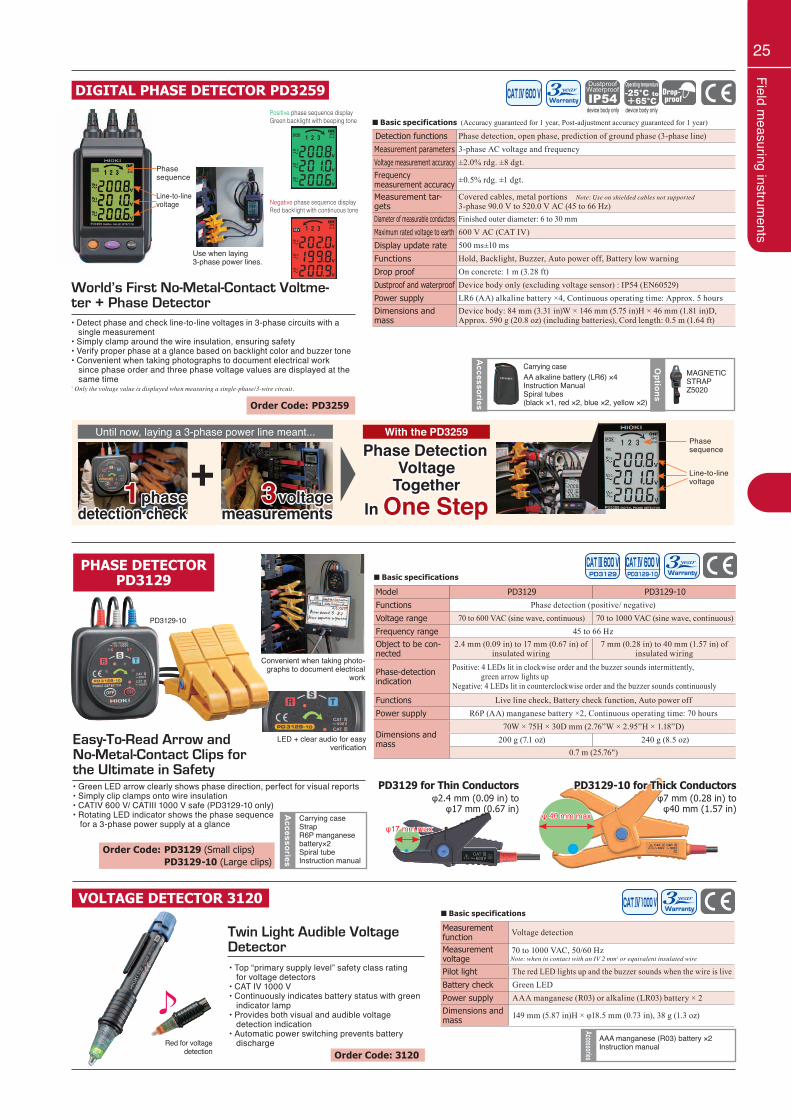
25Field m
easuring instruments
Measurement function Voltage detection
Measurement voltage
70 to 1000 VAC, 50/60 HzNote: when in contact with an IV 2 mm2 or equivalent insulated wire
Pilot light The red LED lights up and the buzzer sounds when the wire is liveBattery check Green LEDPower supply AAA manganese (R03) or alkaline (LR03) battery × 2Dimensions and mass 149 mm (5.87 in)H × φ18.5 mm (0.73 in), 38 g (1.3 oz)
■ Basic specifications
Red for voltagedetection
Twin Light Audible Voltage Detector• Top “primary supply level” safety class rating for voltage detectors• CAT IV 1000 V• Continuously indicates battery status with green indicator lamp• Provides both visual and audible voltage detection indication• Automatic power switching prevents battery discharge
VOLTAGE DETECTOR 3120
AAA manganese (R03) battery ×2Instruction manual
AccessoriesOrder Code: 3120
LED + clear audio for easy verification
Convenient when taking photo-graphs to document electrical
work
PHASE DETECTORPD3129 ■ Basic specifications
Model PD3129 PD3129-10Functions Phase detection (positive/ negative)Voltage range 70 to 600 VAC (sine wave, continuous) 70 to 1000 VAC (sine wave, continuous)Frequency range 45 to 66 HzObject to be con-nected
2.4 mm (0.09 in) to 17 mm (0.67 in) of insulated wiring
7 mm (0.28 in) to 40 mm (1.57 in) of insulated wiring
Phase-detection indication
Positive: 4 LEDs lit in clockwise order and the buzzer sounds intermittently, green arrow lights upNegative: 4 LEDs lit in counterclockwise order and the buzzer sounds continuously
Functions Live line check, Battery check function, Auto power offPower supply R6P (AA) manganese battery ×2, Continuous operating time: 70 hours
Dimensions and mass
70W × 75H × 30D mm (2.76”W × 2.95”H × 1.18”D)200 g (7.1 oz) 240 g (8.5 oz)
0.7 m (25.76")
φ17 mm maxφ 40 mm max
Easy-To-Read Arrow and No-Metal-Contact Clips for the Ultimate in Safety• Green LED arrow clearly shows phase direction, perfect for visual reports• Simply clip clamps onto wire insulation• CATIV 600 V/ CATIII 1000 V safe (PD3129-10 only)• Rotating LED indicator shows the phase sequence for a 3-phase power supply at a glance
Carrying caseStrapR6P manganese battery×2Spiral tubeInstruction manual
Accessories
PD3129-10
Order Code: PD3129 (Small clips) PD3129-10 (Large clips)
PD3129 for Thin Conductorsφ2.4 mm (0.09 in) to
φ17 mm (0.67 in)
PD3129-10 for Thick Conductorsφ7 mm (0.28 in) to
φ40 mm (1.57 in)
■ Basic specifications (Accuracy guaranteed for 1 year, Post-adjustment accuracy guaranteed for 1 year)
DIGITAL PHASE DETECTOR PD3259
Order Code: PD3259
World’s First No-Metal-Contact Voltme-ter + Phase Detector• Detect phase and check line-to-line voltages in 3-phase circuits with a single measurement• Simply clamp around the wire insulation, ensuring safety• Verify proper phase at a glance based on backlight color and buzzer tone• Convenient when taking photographs to document electrical work since phase order and three phase voltage values are displayed at the same time* Only the voltage value is displayed when measuring a single-phase/3-wire circuit.
Accessories
Options
AA alkaline battery (LR6) ×4Instruction ManualSpiral tubes(black ×1, red ×2, blue ×2, yellow ×2)
Carrying caseMAGNETIC STRAPZ5020
Use when laying 3-phase power lines.
V1-2
V
V
VV3-1
V2-3
REV 1 2 3 APS
Positive phase sequence displayGreen backlight with beeping tone
Negative phase sequence displayRed backlight with continuous tone
V1-2
V
V
VV3-1
V2-3
POS 1 2 3 APS Detection functions Phase detection, open phase, prediction of ground phase (3-phase line) Measurement parameters 3-phase AC voltage and frequencyVoltage measurement accuracy ±2.0% rdg. ±8 dgt.Frequencymeasurement accuracy ±0.5% rdg. ±1 dgt.
Measurement tar-gets
Covered cables, metal portions Note: Use on shielded cables not supported3-phase 90.0 V to 520.0 V AC (45 to 66 Hz)
Diameter of measurable conductors Finished outer diameter: 6 to 30 mmMaximum rated voltage to earth 600 V AC (CAT IV)Display update rate 500 ms±10 msFunctions Hold, Backlight, Buzzer, Auto power off, Battery low warningDrop proof On concrete: 1 m (3.28 ft)Dustproof and waterproof Device body only (excluding voltage sensor) : IP54 (EN60529)Power supply LR6 (AA) alkaline battery ×4, Continuous operating time: Approx. 5 hoursDimensions and mass
Device body: 84 mm (3.31 in)W × 146 mm (5.75 in)H × 46 mm (1.81 in)D, Approx. 590 g (20.8 oz) (including batteries), Cord length: 0.5 m (1.64 ft)
Phasesequence
Line-to-linevoltage
device body only device body only
Until now, laying a 3-phase power line meant... With the PD3259
Phase Detection Voltage
TogetherIn One Step
+Phasesequence
Line-to-linevoltage1 phase
detection check3 voltage
measurements
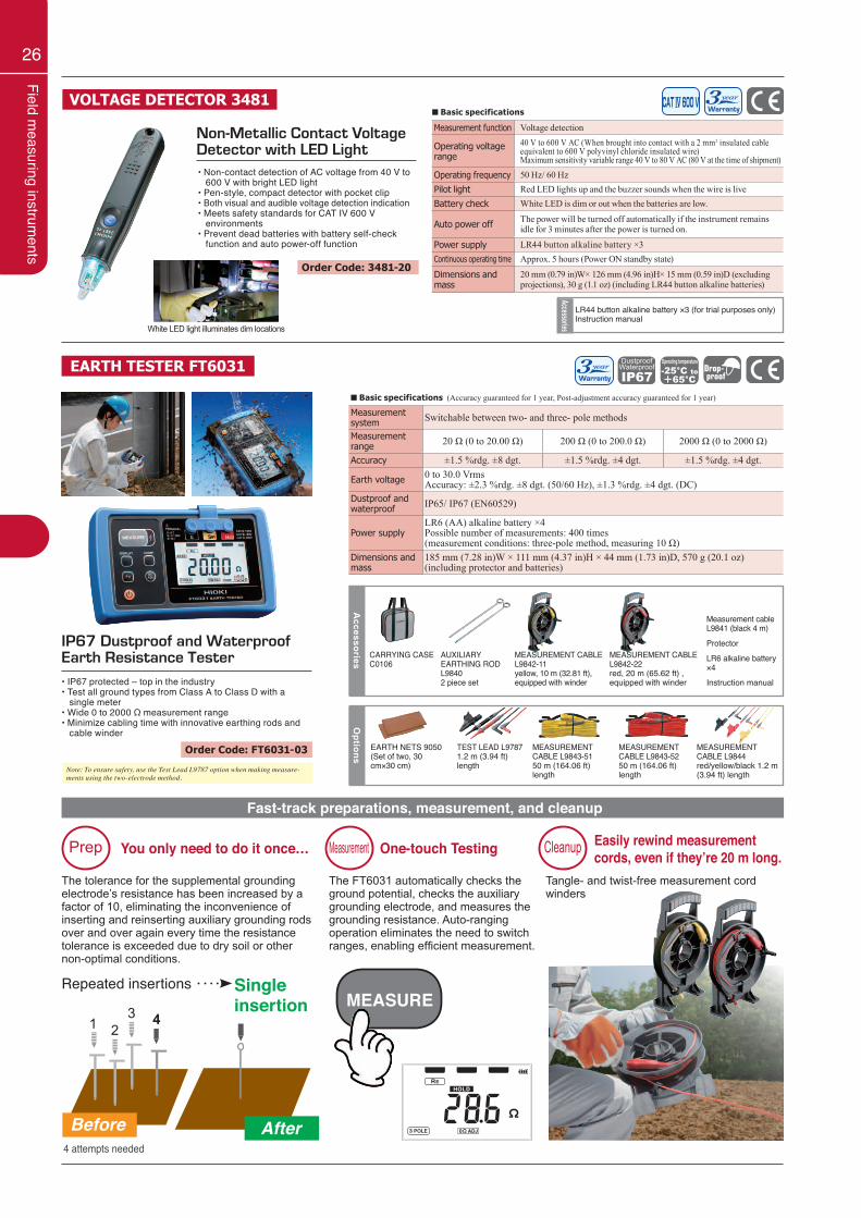
26
Field measuring instrum
ents
EARTH TESTER FT6031
IP67 Dustproof and Waterproof Earth Resistance Tester• IP67 protected – top in the industry• Test all ground types from Class A to Class D with a single meter• Wide 0 to 2000 Ω measurement range• Minimize cabling time with innovative earthing rods and cable winder
Options
EARTH NETS 9050(Set of two, 30 cm×30 cm)
TEST LEAD L97871.2 m (3.94 ft) length
MEASUREMENT CABLE L9843-5150 m (164.06 ft) length
MEASUREMENT CABLE L9843-5250 m (164.06 ft) length
MEASUREMENT CABLE L9844red/yellow/black 1.2 m (3.94 ft) length
Accessories CARRYING CASE
C0106AUXILIARY EARTHING ROD L98402 piece set
Measurement cable L9841 (black 4 m)
Protector
LR6 alkaline battery ×4
Instruction manual
MEASUREMENT CABLE L9842-11yellow, 10 m (32.81 ft), equipped with winder
MEASUREMENT CABLE L9842-22red, 20 m (65.62 ft) , equipped with winder
Fast-track preparations, measurement, and cleanup
The tolerance for the supplemental grounding electrode’s resistance has been increased by a factor of 10, eliminating the inconvenience of inserting and reinserting auxiliary grounding rods over and over again every time the resistance tolerance is exceeded due to dry soil or other non-optimal conditions.
1
Before After
You only need to do it once… One-touch Testing Easily rewind measurement cords, even if they’re 20 m long.
Single insertion
Repeated insertionsMEASURE
Prep Measurement Cleanup
The FT6031 automatically checks the ground potential, checks the auxiliary grounding electrode, and measures the grounding resistance. Auto-ranging operation eliminates the need to switch ranges, enabling efficient measurement.
Tangle- and twist-free measurement cord winders
Order Code: FT6031-03
■ Basic specifications (Accuracy guaranteed for 1 year, Post-adjustment accuracy guaranteed for 1 year)
Measurement system Switchable between two- and three- pole methods
Measurement range 20 Ω (0 to 20.00 Ω) 200 Ω (0 to 200.0 Ω) 2000 Ω (0 to 2000 Ω)
Accuracy ±1.5 %rdg. ±8 dgt. ±1.5 %rdg. ±4 dgt. ±1.5 %rdg. ±4 dgt.
Earth voltage 0 to 30.0 VrmsAccuracy: ±2.3 %rdg. ±8 dgt. (50/60 Hz), ±1.3 %rdg. ±4 dgt. (DC)
Dustproof and waterproof IP65/ IP67 (EN60529)
Power supplyLR6 (AA) alkaline battery ×4Possible number of measurements: 400 times (measurement conditions: three-pole method, measuring 10 Ω)
Dimensions and mass
185 mm (7.28 in)W × 111 mm (4.37 in)H × 44 mm (1.73 in)D, 570 g (20.1 oz)(including protector and batteries)
4 attempts needed
23 4
■ Basic specifications
Non-Metallic Contact Voltage Detector with LED Light• Non-contact detection of AC voltage from 40 V to 600 V with bright LED light• Pen-style, compact detector with pocket clip• Both visual and audible voltage detection indication• Meets safety standards for CAT IV 600 V environments • Prevent dead batteries with battery self-check function and auto power-off function
VOLTAGE DETECTOR 3481
LR44 button alkaline battery ×3 (for trial purposes only)Instruction manual
Accessories
Order Code: 3481-20
White LED light illuminates dim locations
Measurement function Voltage detection
Operating voltage range
40 V to 600 V AC (When brought into contact with a 2 mm2 insulated cable equivalent to 600 V polyvinyl chloride insulated wire)Maximum sensitivity variable range 40 V to 80 V AC (80 V at the time of shipment)
Operating frequency 50 Hz/ 60 HzPilot light Red LED lights up and the buzzer sounds when the wire is liveBattery check White LED is dim or out when the batteries are low.
Auto power off The power will be turned off automatically if the instrument remains idle for 3 minutes after the power is turned on.
Power supply LR44 button alkaline battery ×3Continuous operating time Approx. 5 hours (Power ON standby state)
Dimensions and mass
20 mm (0.79 in)W× 126 mm (4.96 in)H× 15 mm (0.59 in)D (excluding projections), 30 g (1.1 oz) (including LR44 button alkaline batteries)
Note: To ensure safety, use the Test Lead L9787 option when making measure-ments using the two-electrode method.
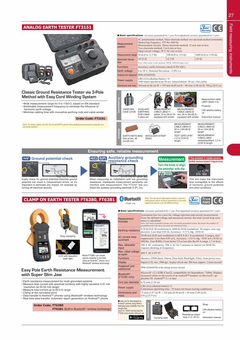
27Field m
easuring instruments
CLAMP ON EARTH TESTER FT6380, FT6381
Easy Pole Earth Resistance Measurement with Super Slim Jaw• Earth resistance measurement for multi-grounded systems• Measure leak current with absolute certainty with highly sensitive 0.01 mA resolution (at 20.00 mA range)• Measure load current up to 60.0 A range• Clamp at the narrowest point• Data transfer to Android™ phones using Bluetooth® wireless technology• Real time data transfer, automatic report generation on Android™ phone
Accessories
Carrying caseResistance check loop (1 Ω, 25 Ω)
Strap
LR6 alkaline battery ×2
Instruction manual
LCD with beautiful back light
Easy clamping
Model FT6381 can create reports instantly in the field using an AndroidTM phone via a Bluetooth® wireless technology
FT6381 only
Order Code: FT6380 FT6381 (Built-in Bluetooth® wireless technology)
■ Basic specifications (Accuracy guaranteed for 1 year, Post-adjustment accuracy guaranteed for 1 year)
Measurement Principle
Instrument has two cores for voltage injection and current measurement. From the defined voltage and measured current, the total circuit loop resis-tance is calculatedNote: For multi grounded systems only. In a multi-grounded system, the larger the number of grounding poles, the more accurate the measured value.
Earthing resistance 0.20 Ω (0.01 Ω resolution) to 1600 Ω (20 Ω resolution), 10 ranges, zero sup-pression: Less than 0.02 Ω, Accuracy: ±1.5 % rdg. ±0.02 Ω
AC current mea-surement
20.00 mA (0.01 mA resolution) to 60.0 A (0.1 A resolution), 5 ranges, zero suppression: Less than 0.05 mA, Accuracy: ±2.0 % rdg. ±0.05 mA (30 Hz to 400 Hz, True RMS), Crest factor 5.0 or less (for the 60 A range, 1.7 or less)
Max. allowable input
100 A AC continuous, 200 A AC for 2 minutes or shorter (at 50/60 Hz, requires derating at frequency)
Max. rated voltage to earth 600 V AC CAT IV
Functions Memory (2000 data), Alarm, Data hold, Backlight, Filter, Auto power saveDisplay Digital LCD, max. 2000 dgt., display refresh rate: 500 msec (approx. 2 times/second)Dustproof andwaterproof IP40 (EN60529) with clamp sensor closed
Bluetooth®
(FT6381 only)
Bluetooth® v2.1+EDR (Class2), compatibility for Smartphone / Tablet, Displays measured values on the screen of an Android™ handset via Bluetooth®, ap-plicable OS: Android™ 2.1 or later
Core jaw diameter φ 32 mm (1.26 in)
Power supply LR6 (AA) alkaline battery×2Continuous operating time : 35 hours (in-house testing conditions)
Dimensions and mass
73 mm (2.87 in) W × 218 mm (8.58 in) H × 43 mm (1.69 in) D,620 g (21.9 oz)
■ Basic specifications (Accuracy guaranteed for 1 year, Post-adjustment accuracy guaranteed for 1 year)
Measurement system
AC potentiometer method, Three-electrode method/ two-electrode method (switchable)Measuring frequency: 575 Hz/ 600 HzMeasurement current: Three-electrode method: 15 mA rms or less;Two-electrode method: 3 mA rms or lessOpen circuit voltage: 50 V AC rms or less
Measurement range 10 Ω (0 to 11.5 Ω) 100 Ω (0 to 115 Ω) 1000 Ω (0 to 1150 Ω)
Nominal Devia-tion
±0.25 Ω ±2.5 Ω ±25 ΩNote: when using 2-pole method, 100 Ω, 1000 Ω ranges only
Functions Auxiliary earth resistance check S (P)/ H(C)Earth voltage 0 to 30 V, Nominal Deviation: ±3.0% f.s.Dustproof and waterproof IP40 (EN60529)
Power supply LR6 (AA) alkaline battery ×61100 times operation (at 30 sec. measurement/ 30 sec. rest cycle)
Dimensions and mass 164 mm (6.46 in) W × 119 mm (4.69 in) H × 88 mm (3.46 in) D, 760 g (26.8 oz)
ANALOG EARTH TESTER FT3151
Classic Ground Resistance Tester via 3-Pole Method with Easy Cord Winding System• Wide measurement range for 0 to 1150 Ω, based on EN standard• Switchable measurement frequency to minimize the influence of harmonic earth voltage• Minimize cabling time with innovative earthing rods and cable winder
Order Code: FT3151O
ptions EARTH NETS 9050(Set of two, 30 cm×30 cm)
SHOULDER STRAPZ5022
TEST LEAD L97871.2 m (3.94 ft) length
MEASUREMENT CABLE L9843-5150 m (164.06 ft) length
MEASUREMENT CABLE L9843-5250 m (164.06 ft) lengthMEASUREMENT CABLE L9844red/yellow/black 1.2 m (3.94 ft) length
Accessories CARRYING
CASE C0106AUXILIARY EARTHING ROD L98402 piece set
Measurement cable L9841 (black 4 m)
Protector
LR6 alkaline battery ×6
Instruction manual
MEASUREMENT CABLE L9842-11yellow, 10 m (32.81 ft), equipped with winder
MEASUREMENT CABLE L9842-22red, 20 m (65.62 ft) , equipped with winder
■ Data can be downloaded to AndroidTM phones using Hioki’s dedicated apps available from the Google Play. Search for “HIOKI” and download the “FT6381 Communication Software” app.
Note: For the latest information about countries and regions where wireless operation is currently supported, please visit the Hioki website.
Ensuring safe, reliable measurementGround potential check Auxiliary grounding
resistance check
When measuring an installation with low grounding resistance, inadequate measurement sensitivity can interfere with measurement. The FT3151 lets you check the auxiliary grounding electrode S (P), too.
This will make the instrument less susceptible to the effects of harmonic ground potential and other conditions.
Easily check for ground potential.Distorted ground potential can result in measurement errors, so it’s important to eliminate any impact, for example by turning off electrical devices.
Turn the knob to alignMeasurement Switch measurement frequencies.
If the ammeter’s needle wavers…H(C) S(P)
▼ ▼V
Within 5 kΩ (within green bar)Read from the scale
the ammeter with the [ ▼ ] mark.
Note: To ensure safety, use the Test Lead L9787 option when making measurements using the two-electrode method.
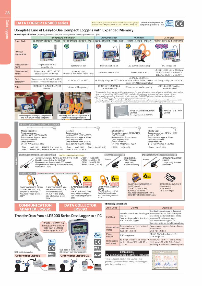
Data loggers
28
Complete Line of Easy-to-Use Compact Loggers with Expanded Memory
DATA LOGGER LR5000 series Note: Analysis of measurement data on a PC requires the optional Communication Adapter LR5091 or Data Collector LR5092-20.
*1 Representative figures are provided for basic accuracy. For more information, please refer to the individual product catalogs. Accuracy for the LR5001, LR5011, and LR5051 is calculated by adding the instrument and sensor accuracy figures. For more information about the accuracy of other sensors for the LR5051, please see individual product catalogs.*2 Current and leak current that occur intermittently cannot be measured. The Clamp Logger LR5051 may be affected by high-frequency noise during leak current measurement. Please contact Hioki for more information if you plan to use the instrument in an environment where it would be affected by such noise.
Recording and managing temperature and humidity in offices and plants
Recording and measuring current in plant and building equipment
Options
MAGNETIC STRAP Z5004
WALL-MOUNTED HOLDER LR9901Not compatible with Model LR5051
Temperature or humidity Instrumentation AC current DC voltageOrder Code HUMIDITY LOGGER LR5001 TEMPERATURE LOGGER LR5011 INSTRUMENTATION LOGGER LR5031 CLAMP LOGGER LR5051*2 VOLTAGE LOGGER LR5041, LR5042, LR5043
Physicalappearance
Measurement items
Temperature 1ch and humidity 1ch Temperature 1ch Instrumentation 1ch AC current (2 channels) DC voltage 1ch
Measurement range
Temperature : -40°C to 85°CHumidity : 0% to 100%rh
-40.0˚C to 180˚C*Depends on measurement range of sensor. -30.00 to 30.00mA DC 0.00 to 1000 A AC
LR5041: -50.00 mV to 50.00 mVLR5042: -5.000 V to 5.000 VLR5043: -50.00 V to 50.00 V
Basic accuracy*1
Temperature : ±0.5°C(at 0°C to 35°C )Humidity : ±5%rh(at 50%rh or less, 25°C) ±0.5˚C (at 0˚C to 35˚C ) ±0.5%rdg. ±5dgt. (at 23˚C±5˚C)
±2.0%rdg. ±0.13% f.s.(at Main unit+ CT6500, 500.0 A range, 50/60 Hz typical value)
±0.5%rdg. ±5dgt. (at 23°C±5°C)
Other HUMIDITY SENSOR LR9504 bundled Sensor sold separately CONNECTION CABLE
LR9801 bundled Clamp sensor sold separately CONNECTION CABLE LR9802 bundled
Order Code LR5091 LR5092-20
Function
Transfer data from a data logger to a PC.Send settings and the time from a PC to a data logger.
Send data from a data logger to the internal memory or an SD card, then display a graph. Send settings and the time from the internal memory or SD card to a data logger. Send data from a data logger to a PC. Send settings and the time from a PC to a data logger.
Communications method
Between data loggers: Infrared communicationsWith PC: USB 2.0
Between data loggers: Infrared com-municationsWith PC: USB 2.0
Power supply USB bus power LR6 (AA) alkaline battery ×2
USB bus power
Dimensions and mass
83 mm(3.27 in)W × 61 mm(2.40 in) H × 19 mm(0.75 in)D, 43 g (1.5 oz)
91 mm(3.58 in)W×141 mm(5.55 in)H×31 mm(1.22 in)D, 215 g(7.6 oz) (excluding batteries and SD memory card)
Transfer Data from a LR5000 Series Data Logger to a PC
COMMUNICATION ADAPTER LR5091
DATA COLLECTORLR5092
USB cable is bundledUSB cable is bundledSD memory card sold separately. LR5000 Utility
(PC communications software; included)Table and graph display, data analysis, data processing transmission of setting to data loggers, print functionality, etc.
LR5091 or LR5092-20 is necessary to transfer
data from a LR5000 series logger to a PC
■ Basic specifications
Options
(Lug type)Temperature range : -30°C to 180°C (-22˚F to 356˚F)Response time : Approx. 45 sec (90% response time)Outer diameter: 7 mm (0.26 in)Inner diameter: 3.2 mm (0.13 in)LR9611 1 m (3.28 ft) LR9612 5 m (16.41 ft)LR9613 10 m (32.81 ft)
(Sheathed type)Temperature range : -40°C to 120°C (-40˚F to 248˚F)Response time : Approx. 90 sec (90% response time)Sensor head size:φ 4 × 180 mm (0.16in × 7.09 in)LR9621 1 m (3.28 ft)
(Needle type)Temperature range : -40°C to 120°C (-40˚F to 248˚F)Response time : Approx. 20 sec(90% response time)Sensor head size:φ 1.3 × 25 mm (0.05 in × 0.98 in)LR9631 1 m (3.28 ft)LR9601 1 m (3.28 ft) LR9602 5 m (16.41 ft)
LR9603 10 m (32.81 ft) LR9604 45 mm (1.77 in)
(Molded plastic type)Temperature range : -40°C to 180°C (-40˚F to 356˚F)Response time : Approx. 100 sec(90% response time)Sensor head size:φ 6 × 28 mm (0.24 in×1.10 in)
LR5011 options: TEMPERATURE SENSOR
LR5001 options: HUMIDITY SENSOR
LR5051 options
Temperature range : -40 °C to 85 °C (-40˚F to 185˚F)Humidity range : 0.0%rh to 100.0%rhResponse time : Approximately 300 seconds(Temperature and humidity; 90% response time)Waterproof : None
LR9501 1 m (3.28 ft)LR9502 5 m (16.41 ft)LR9503 10 m (32.81 ft) LR9504 40 mm (1.57 in)
CLAMP ON SENSOR CT6500500 A AC, φ46 mm (1.81") ,3 m (9.84 ft) cord length,Max. rated voltage to earth : 600 V
CLAMP ON SENSOR 96691000 A AC, φ55 mm (2.17") , 80 mm×20 mm busbar,3 m (9.84 ft) cord length,Max. rated voltage to earth : 600 V
CONNECTION CABLE 9219For connecting Model 9695-023 m (9.84 ft) length
CLAMP ON SENSOR 9695-02Not CE marked50 A AC, φ15 mm (0.59") ,80 mm×20 mm busbarMax. rated voltage to earth : 300 VCONNECTION CABLE 9219 required
LR5031 accessoriesCONNECTION CABLE LR98011 m (3.28 ft), Bundled accessory
2 wires
LR5041, LR5042, LR5043 accessoriesCONNECTION CABLE LR98021 m (3.28 ft), Bundled accessory
4 wires
Order code: LR5092-20
CLAMP ON LEAK SENSOR 9675*5 A AC , φ30 mm (1.18 in),3 m (9.84 ft) cord lengthMax. rated voltage to earth:300 V
LeakageCurrent
CLAMP ON LEAK SENSOR 9657-10*5 A AC, φ40 mm (1.57 in),3 m (9.84 ft) cord lengthMax. rated voltage to earth: 300 V
LeakageCurrent
■ Basic specifications (Accuracy guaranteed for 1 year, Post-adjustment accuracy guaranteed for 1 year)
Note: LR9504 is bundled accessory.
Order code: LR5091
*Maximum measurable current when used with the LR5051
Temperature/humidity sensors and clamp sensors guaranteed for 1 year.
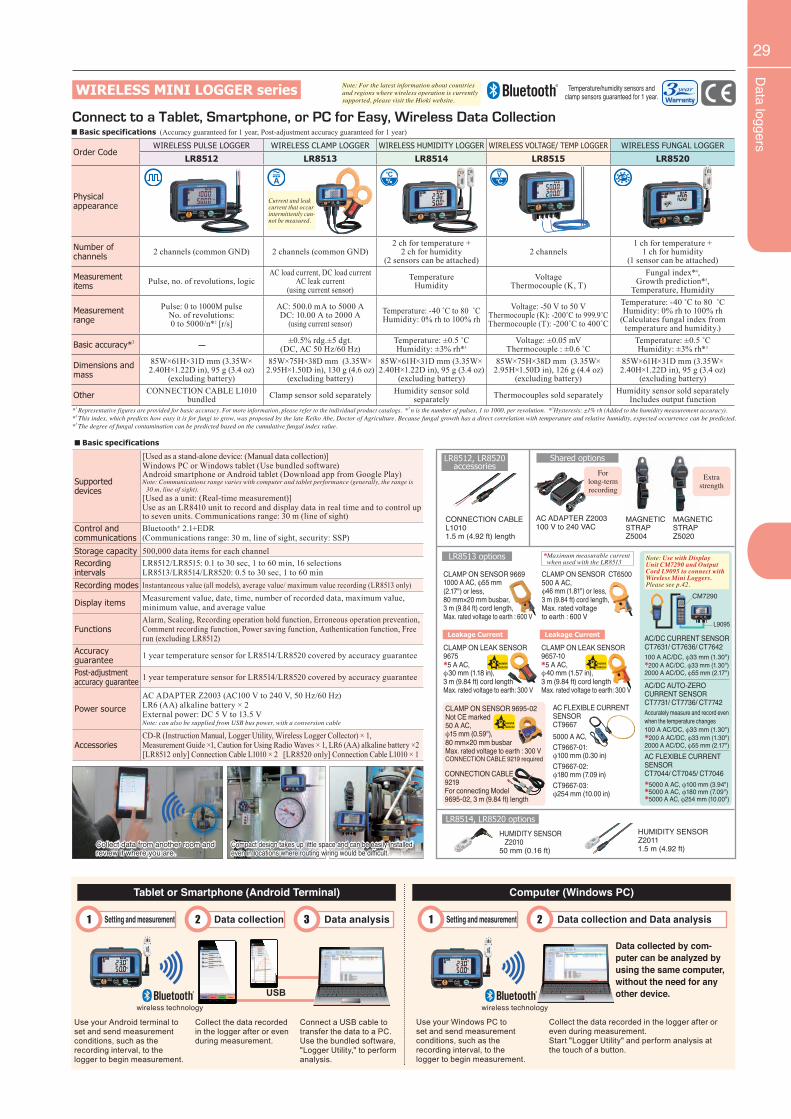
Data loggers
29
CLAMP ON SENSOR 96691000 A AC, φ55 mm(2.17") or less,80 mm×20 mm busbar,3 m (9.84 ft) cord length,Max. rated voltage to earth : 600 V
*1 Representative figures are provided for basic accuracy. For more information, please refer to the individual product catalogs. *2 n is the number of pulses, 1 to 1000, per revolution. *3Hysteresis: ±1% rh (Added to the humidity measurement accuracy).*4 This index, which predicts how easy it is for fungi to grow, was proposed by the late Keiko Abe, Doctor of Agriculture. Because fungal growth has a direct correlation with temperature and relative humidity, expected occurrence can be predicted. *5 The degree of fungal contamination can be predicted based on the cumulative fungal index value.
Connect to a Tablet, Smartphone, or PC for Easy, Wireless Data Collection
WIRELESS MINI LOGGER series
Order CodeWIRELESS PULSE LOGGER WIRELESS CLAMP LOGGER WIRELESS HUMIDITY LOGGER WIRELESS VOLTAGE/ TEMP LOGGER WIRELESS FUNGAL LOGGER
LR8512 LR8513 LR8514 LR8515 LR8520
Physicalappearance
Number ofchannels 2 channels (common GND) 2 channels (common GND)
2 ch for temperature + 2 ch for humidity
(2 sensors can be attached)2 channels
1 ch for temperature + 1 ch for humidity
(1 sensor can be attached)
Measurement items Pulse, no. of revolutions, logic
AC load current, DC load currentAC leak current
(using current sensor)Temperature
HumidityVoltage
Thermocouple (K, T)Fungal index*4,
Growth prediction*5,Temperature, Humidity
Measurementrange
Pulse: 0 to 1000M pulseNo. of revolutions: 0 to 5000/n*2 [r/s]
AC: 500.0 mA to 5000 ADC: 10.00 A to 2000 A
(using current sensor)Temperature: -40 ˚C to 80 ˚CHumidity: 0% rh to 100% rh
Voltage: -50 V to 50 VThermocouple (K): -200˚C to 999.9˚CThermocouple (T): -200˚C to 400˚C
Temperature: -40 ˚C to 80 ˚CHumidity: 0% rh to 100% rh
(Calculates fungal index from temperature and humidity.)
Basic accuracy*1 ±0.5% rdg.±5 dgt.(DC, AC 50 Hz/60 Hz)
Temperature: ±0.5 ˚CHumidity: ±3% rh*3
Voltage: ±0.05 mVThermocouple : ±0.6 ˚C
Temperature: ±0.5 ˚CHumidity: ±3% rh*3
Dimensions and mass
85W×61H×31D mm (3.35W× 2.40H×1.22D in), 95 g (3.4 oz)
(excluding battery)
85W×75H×38D mm (3.35W× 2.95H×1.50D in), 130 g (4.6 oz)
(excluding battery)
85W×61H×31D mm (3.35W× 2.40H×1.22D in), 95 g (3.4 oz)
(excluding battery)
85W×75H×38D mm (3.35W× 2.95H×1.50D in), 126 g (4.4 oz)
(excluding battery)
85W×61H×31D mm (3.35W× 2.40H×1.22D in), 95 g (3.4 oz)
(excluding battery)
Other CONNECTION CABLE L1010 bundled Clamp sensor sold separately Humidity sensor sold
separately Thermocouples sold separately Humidity sensor sold separatelyIncludes output function
LR8513 options
LR8514, LR8520 options
CLAMP ON SENSOR CT6500500 A AC,φ46 mm (1.81") or less,3 m (9.84 ft) cord length,Max. rated voltageto earth : 600 V
CLAMP ON LEAK SENSOR 9675*5 A AC,φ30 mm (1.18 in),3 m (9.84 ft) cord lengthMax. rated voltage to earth: 300 V
HUMIDITY SENSOR Z2010
50 mm (0.16 ft)
HUMIDITY SENSOR Z20111.5 m (4.92 ft)
Shared options
AC ADAPTER Z2003100 V to 240 VAC
MAGNETIC STRAP Z5004
MAGNETIC STRAP Z5020
Forlong-termrecording
Extra strength
LR8512, LR8520 accessories
CONNECTION CABLE L10101.5 m (4.92 ft) length
CONNECTION CABLE9219For connecting Model 9695-02, 3 m (9.84 ft) length
Collect data from another room and review it where you are.
Compact design takes up little space and can be easily installed even in locations where routing wiring would be difficult.
Tablet or Smartphone (Android Terminal) Computer (Windows PC)
Use your Android terminal to set and send measurement conditions, such as the recording interval, to the logger to begin measurement.
Use your Windows PC to set and send measurement conditions, such as the recording interval, to the logger to begin measurement.
Collect the data recorded in the logger after or even during measurement.
Connect a USB cable to transfer the data to a PC.Use the bundled software, "Logger Utility," to perform analysis.
wireless technology wireless technology
Data collected by com-puter can be analyzed by using the same computer, without the need for any other device.
Data collection Data collection and Data analysis Data analysis Setting and measurement1 Setting and measurement12 23
USB
Collect the data recorded in the logger after or even during measurement.Start "Logger Utility" and perform analysis at the touch of a button.
■ Basic specifications (Accuracy guaranteed for 1 year, Post-adjustment accuracy guaranteed for 1 year)
Current and leak current that occur intermittently can-not be measured.
Leakage Current
■ Basic specifications
Supported devices
[Used as a stand-alone device: (Manual data collection)]Windows PC or Windows tablet (Use bundled software)Android smartphone or Android tablet (Download app from Google Play)Note: Communications range varies with computer and tablet performance (generally, the range is
30 m, line of sight).[Used as a unit: (Real-time measurement)]Use as an LR8410 unit to record and display data in real time and to control up to seven units. Communications range: 30 m (line of sight)
Control andcommunications
Bluetooth® 2.1+EDR(Communications range: 30 m, line of sight, security: SSP)
Storage capacity 500,000 data items for each channelRecordingintervals
LR8512/LR8515: 0.1 to 30 sec, 1 to 60 min, 16 selectionsLR8513/LR8514/LR8520: 0.5 to 30 sec, 1 to 60 min
Recording modes Instantaneous value (all models), average value/ maximum value recording (LR8513 only)
Display items Measurement value, date, time, number of recorded data, maximum value, minimum value, and average value
FunctionsAlarm, Scaling, Recording operation hold function, Erroneous operation prevention, Comment recording function, Power saving function, Authentication function, Free run (excluding LR8512)
Accuracyguarantee 1 year temperature sensor for LR8514/LR8520 covered by accuracy guarantee
Post-adjustment accuracy guarantee 1 year temperature sensor for LR8514/LR8520 covered by accuracy guarantee
Power source
AC ADAPTER Z2003 (AC100 V to 240 V, 50 Hz/60 Hz)LR6 (AA) alkaline battery × 2 External power: DC 5 V to 13.5 V Note: can also be supplied from USB bus power, with a conversion cable
AccessoriesCD-R (Instruction Manual, Logger Utility, Wireless Logger Collector) × 1, Measurement Guide ×1, Caution for Using Radio Waves × 1, LR6 (AA) alkaline battery ×2 [LR8512 only] Connection Cable L1010 × 2 [LR8520 only] Connection Cable L1010 × 1
AC/DC CURRENT SENSOR CT7631/ CT7636/ CT7642100 A AC/DC, φ33 mm (1.30")*200 A AC/DC, φ33 mm (1.30")2000 A AC/DC, φ55 mm (2.17")
AC/DC AUTO-ZERO CURRENT SENSOR CT7731/ CT7736/ CT7742Accurately measure and record even when the temperature changes100 A AC/DC, φ33 mm (1.30")*200 A AC/DC, φ33 mm (1.30")2000 A AC/DC, φ55 mm (2.17")AC FLEXIBLE CURRENT SENSORCT7044/ CT7045/ CT7046*5000 A AC, φ100 mm (3.94")*5000 A AC, φ180 mm (7.09")*5000 A AC, φ254 mm (10.00")
Note: For the latest information about countries and regions where wireless operation is currently supported, please visit the Hioki website.
*Maximum measurable current when used with the LR8513
CLAMP ON LEAK SENSOR 9657-10*5 A AC, φ40 mm (1.57 in),3 m (9.84 ft) cord lengthMax. rated voltage to earth: 300 V
Leakage Current
CLAMP ON SENSOR 9695-02Not CE marked50 A AC,φ15 mm (0.59"),80 mm×20 mm busbarMax. rated voltage to earth : 300 VCONNECTION CABLE 9219 required
AC FLEXIBLE CURRENT SENSOR CT96675000 A AC,CT9667-01: φ100 mm (0.30 in)CT9667-02:φ180 mm (7.09 in)CT9667-03:φ254 mm (10.00 in)
Note: Use with Display Unit CM7290 and Output Cord L9095 to connect with Wireless Mini Loggers. Please see p.42.
L9095
CM7290
Temperature/humidity sensors and clamp sensors guaranteed for 1 year.
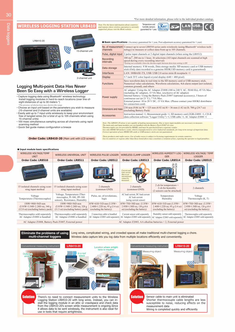
Data loggers
30
WIRELESS LOGGING STATION LR8410
Logging Multi-point Data Has Never Been So Easy with a Wireless Logger• Capture logging data using Bluetooth® wireless technology Install logging modules in hard-to-reach locations (over line-of- sight distances of up to 30 meters *) *The presence of obstructions may shorten this range• Choose an input unit based on the parameters you wish to measure (15-channel and 2-channel units are available)• Easily add up to 7 input units wirelessly to keep your environment free of tangled wires (for a total of up to 105 channels when using 15-channel units)• 100 msec simultaneous sampling across all channels using rapid scanning method• Quick Set guide makes configuration a breeze
LR8410-20
15-channel unit
2-channel unit
Order Code: LR8410-20 (Main unit with LCD screen)
■ Basic specifications (Accuracy guaranteed for 1 year, Post-adjustment accuracy guaranteed for 1 year)
No. of measurementchannels
Connect up to seven LR8510 series units wirelessly (using Bluetooth® wireless tech-nology) to measure or collect data from up to 105 channels.
Pulse, digital input 2 pulse input channels or 2 digital input channels (when using the LR8512)
Recordingintervals
100 ms*, 200 ms to 1 hour, 16 selections (All input channels are scanned at high speed during every recording interval)*Setting not available when the thermocouple burnout detection setting is ON
Data storage Internal memory: 8 M-words, Data storage media: SD memory card or USB memory stick (Only data recorded to a genuine HIOKI SD memory card is guaranteed)
Interfaces LAN: 100BASE-TX, USB: USB 2.0 series mini-B receptacle ×1Display 5.7 inch TFT color liquid crystal display (640 × 480 pixel)
FunctionsSave waveform data in real time to the SD memory card or USB memory stick, Numerical value calculations, Waveform calculations, 4ch alarm output (not isolated, common ground), and others
Power supply
AC adapter: Using the AC Adapter Z1008 (100 to 240 V AC, 50/60 Hz), 45 VA Max. (including AC adapter), 15 VA Max. (exclusive of AC adapter)Internal battery: Using the Battery Pack Z1007 (optional accessory), 3 hours of continuous use (at 23 ˚C), 7 VA Max.External power: 10 to 28 V DC, 15 VA Max. (Please contact your HIOKI distributor for connection cord)
Dimensions and mass 230 mm (9.06 in) W × 125 mm (4.92 in) H × 36 mm (1.42 in) D, 700 g (24.7 oz)(excluding Battery Pack)
Accessories Instruction manual ×1, Measurement guide ×1, SD memory card (2GB) Z4001 ×1, CD-R (data collection software “Logger Utility”) ×1, USB cable ×1, AC Adapter Z1008 ×1
Note: The LR8410-20 alone is not capable of making measurements. One or more input modules are necessary to measure. The main unit and input modules are not bundled with the Battery Pack Z1007 (Li-ion). Thermocouples are not provided by HIOKI, and must be purchased from a separate vendor.Use only HIOKI SD memory cards, which is manufactured to strict industrial standards, for long-term storage of important data.Correct operation of non-HIOKI SD cards or USB memory sticks are not guaranteed.
These products emit radio waves. Use of radio waves is subject to licensing requirements in certain countries. Use in countries or regions other than those listed above may constitute a violation of law, exposing the operator to legal penalties.
*For more detailed information, please refer to the individual product catalogs.
Eliminate the problems of using multi-channel loggers
Long wires, complicated wiring, and crowded spaces all make traditional multi-channel logging a chore. Wireless data capture lets you log data from multiple locations efficiently and conveniently.
There’s no need to connect measurement units to the Wireless Logging Station LR8410-20 with long wires. Instead, you can in-stall the logging module in an attic or crawlspace and check data from the LR8410-20’s screen while measurement is ongoing.Since it allows data to be sent wirelessly, the instrument is also ideal for use in tests that require airtightness.
Sensor cable to main unit is eliminatedShorter thermocouple cable lengths are less susceptible to noise, reducing effects on the measurement dataWiring is completed quickly and efficiently
Conventional measuring instrument Conventional measuring instrument LR8410-20LR8410-20
In a roof space
At an air-conditioner
vent
Outside a window
Location where airtight-ness is required
Crawl space
Measuring object
SolutionSolution
In a roof space
Measuring object
■ Input module basic specifications
WIRELESS VOLTAGE/TEMP UNIT
WIRELESS UNIVERSAL UNIT WIRELESS PULSE LOGGER WIRELESS CLAMP LOGGERWIRELESS HUMIDITY LOG-
GERWIRELESS VOLTAGE/ TEMP
LOGGER
Order Code: LR8510 Order Code: LR8511 Order Code: LR8512 Order Code: LR8513 Order Code: LR8514 Order Code: LR8515
15 isolated channels using scan-ning input method
15 isolated channels using scan-ning input method
2 channels(common GND)
2 channels(common GND)
2 ch for temperature + 2 ch for humidity
(2 sensors can be attached)2 channels
VoltageTemperature (Thermocouples)
Voltage, Temperature (Ther-mocouples, Pt 100, JPt 100
sensor), Resistance, Humidity
Pulse, no. of revolutions, logic
AC load current, DC load currentAC leak current
(using current sensor)
TemperatureHumidity
VoltageThermocouple (K, T)
150W×90H×56D mm (5.91W×3.54H×2.20D in), 340 g
(12.0 oz) (excluding battery pack)
150W×90H×56D mm (5.91W×3.54H×2.20D in), 320 g
(11.3 oz) (excluding battery pack)
85W×61H×31D mm (3.35W× 2.40H×1.22D in), 95 g (3.4 oz) (excluding the battery)
85W×75H×38D mm (3.35W× 2.95H×1.50D in), 130 g (4.6 oz) (excluding the battery)
85W×61H×31D mm (3.35W× 2.40H×1.22D in), 95 g (3.4 oz) (excluding the battery)
85W×75H×38D mm (3.35W× 2.95H×1.50D in), 126 g (4.4 oz) (excluding the battery)
Thermocouples sold separatelyAC Adapter Z1008 is bundled
Thermocouples sold separatelyAC Adapter Z1008 is bundled
Connection cable is bundledAC Adapter Z2003 sold separately
Current sensor sold separatelyAC Adapter Z2003 sold separately
Humidity sensor sold separatelyAC Adapter Z2003 sold separately
Thermocouples sold separatelyAC Adapter Z2003 sold separately
AC Adapter Z1008, Battery Pack Z1007, External power AC Adapter Z2003, AA alkaline batteries × 2, External power
Current and leak current that occur intermittently cannot be measured.
Note: For the latest information about countries and regions where wireless operation is currently supported, please visit the Hioki website.
Temperature and humidity sensors
guaranteed for 1 year.
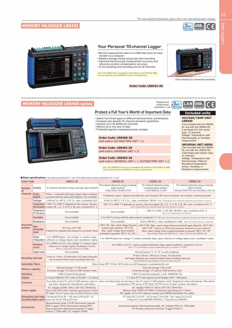
Data loggers
31
MEMORY HiLOGGER LR8431
Your Personal 10-channel Logger• Record measurement data on a USB flash drive for easy transfer to a computer• Replace storage media during real-time recording• Improved thermocouple measurement accuracy and reference junction compensation accuracy• 10 ms sampling and recording across all channels
Ultra-compact for convenient portability
• Select from three types of different terminal block combinations• Compact size despite 30-channel standard capabilities• Expand up to 30 additional channels• Record up to one year of data• Protected against unexpected power outages
Protect a Full Year's Worth of Important Data
Order Code LR8431-20 LR8400-20 LR8401-20 LR8402-20
Number ofchannels
Analog 10 isolated channels using scanning input method30 isolated channels using scanning
input methodVOLTAGE/TEMP UNIT
30 isolated channels usingscanning input method
UNIVERSAL UNIT
30 isolated channels using scanning input method
VOLTAGE/TEMP UNIT 15ch+UNIVERSAL UNIT 15chPulse, Digital
Pulse: 4 channels (all pulse inputs share common ground with the main unit) Digital: Not available 8 channels, pulse / digital selectable for each channel, M3 screw terminal, not isolated, common ground
Measurement parameters
Voltage ±100 mV to ±60 V, 1-5V f.s., max. resolution 5µV 10 mV to 100 V, 1-5 V f.s. , max. resolution: 500 nV Note: Isolated between channels and from each channel to chassis
Temperature (thermocouples)
−200 ˚C to 1800 ˚C (depend on the sensor), thermo-couples (K, J, E, T, N, R, S, B), max. resolution 0.1 ˚C
-200 ˚C to 2000 ˚C (depends on sensor), thermocouples (K, J, E, T, N, R, S, B, W), max. resolution 0.01 ˚CNote: Isolated between channels and from each channel to chassis
Temperature (Pt 100 sensor) Not available Not available -200 ˚C to 800 ˚C (Pt 100, JPt100) , max. resolution 0.01 ˚C
Note: Not isolated between channels
Humidity Not available 5.0 to 95.0 % rh (use with the option sensor), resolution 0.1 % rh Note: Not isolated between channels nor from each channel to chassis
Resistance Not available Not available 0 Ω to 200 Ω f.s., max. resolution 0.5 mΩ Note: Not isolated between channels
Max. allowable input
30 Vrms, 60 V DCChannel-to-channel and channel-to-ground: Same
±100 V DC, Max. rated voltage between isolated input channels: 250 V DC, Max. rated voltage from isolated
terminals to ground: 300 V AC, DC
±100 V DC, Max. rated voltage between isolated input channels: 250 V DC*1,300 V DC*2 (However, RTD and resistance channels are not isolated.)Max. rated voltage from isolated terminals to ground: 300 V AC, DC
*1Note:Voltage/ Temp unit LR8500 only *2Note: Universal unit LR8501 only
Pulseintegration
0 to 1000M pulse, (no-voltage ‘a’ contact, open collector or voltage input), max. resolution 1 pulse 0 to 1000 M pulse (no-voltage 'a' contact; normally open, open collector or voltage input), max. resolution 1 pulse
Rotation count
0 to 5000/n (r/s) f.s. (no-voltage ‘a’ contact, open collector or voltage input), resolution 1/n (r/s)
Note: n = pulses per rotation (1 to 1000)
0 to 5000 /n (r/s) f.s. (same as pulse totalization input signal condition), resolution 1/n (r/s) Note: "n" is the number of sensor output pulses per revolution, 1 to 1000
Digital input Not available Record logical "1" or "0" at each sampling
Recording intervals 10 ms to 1 hour, 19 selections (All input channels are scanned within each recording interval)
10 ms to 50 ms, 100 ms to 1 hour, 19 selections (All input channels are scanned within each recording interval)
Note: limited by using channels at 10 ms to 50 ms interval
Selectable filters Select from OFF/ 50 Hz/ 60 Hz (the cut-off frequency is automatically set)
Memory capacity Internal storage: 3.5 M wordsExternal storage: CF card or USB memory stick
Internal storage: 8 M wordsExternal storage: CF card or USB memory stick
Interfaces USB 2.0 mini-B receptacle USB 2.0 mini-B receptacle, LAN: 100BASE-TXDisplay 4.3-inch WQVGA-TFT color LCD (480 × 272 dots) 5.7 inch TFT color liquid crystal display (640 × 480 pixel)
Functions Save data to the CF card or USB memory stick in real time, Numerical calculations, and others
Save waveform data in real time to the CF card or USB memory stick, Numerical value calculations, Waveform calculations, FTP server, FTP client, HTTP server, E-mail system, and others
Power supplyAC Adapter Z1005: 100 to 240 VAC (50/60 Hz)
Battery Pack 9780 (Ni-MH): Continuous operating time 2.5 hoursDC supply: 10 to 16 V (please contact your HIOKI distributor for cable)
AC Adapter 9418-15: 100 to 240 VAC (50/60 Hz)Battery Pack Z1000 (Ni-MH): Continuous operating time 5 hours
DC supply: 10 to 28 V (please contact your HIOKI distributor for cable)Dimensions and mass(excluding battery pack)
176 mm (6.93 in) W × 101 mm (3.98 in) H × 41 mm (1.61 in) D, 550 g (19.4 oz)
272 mm (10.71 in) W × 182.4 mm (7.18 in) H × 66.5 mm (2.62 in) D1.8 kg (63.5 oz) (LR8400/LR8402), 1.7kg (60 oz) (LR8401)
Accessories
Measurement guide, CD-R (Instruction manual PDF, Logger Utility Instruction manual PDF, Data acquisition application program "Logger Utility"), USB cable, AC Adapter Z1005
Instruction manual, Measurement guide, AC Adapter 9418-15, USB cable,CD-R (data collection software "Logger Utility")
■ Basic specifications (Accuracy guaranteed for 1 year, Post-adjustment accuracy guaranteed for 1 year)
MEMORY HiLOGGER LR8400 series
Note: The LR8400-20 series are not bundled with the Battery Pack Z1000 (Ni-MH). Correct operation of non-HIOKI CF cards is not guaranteed.
Note: The LR8431-20 is not bundled with the Battery Pack 9780 (Ni-MH).Correct operation of non-HIOKI CF cards is not guaranteed.
VOLTAGE/TEMP UNIT LR8500 (Two included with the LR8400-20, one with the LR8402-20)2 terminals M-3 mm screw type, 15 channelsVoltage, Temperature with thermocouple, or Humidity measurement
Included units
UNIVERSAL UNIT LR8501(Two included with the LR8401-20, one with the LR8402-20)4 terminals push-button type, 15 channelsVoltage, Temperature with thermocouple, Platinum Resistance temperature sensor, Humidity, or Resistance measurement
Order Code: LR8400-20(with built-in VOLTAGE/TEMP UNIT × 2)
Order Code: LR8401-20(with built-in UNIVERSAL UNIT × 2)
Order Code: LR8402-20(with built-in UNIVERSAL UNIT × 1, VOLTAGE/TEMP UNIT × 1)
*For more detailed information, please refer to the individual product catalogs.
Order Code: LR8431-20
Temperature and humidity sensors
guaranteed for 1 year.
32
Temperature testers
■ Basic specifications (Accuracy guaranteed for 6 months, Post-adjustment accuracy guaranteed for 6 months)
Measurement range −100 to 1300 ˚C (-148 °F to 2372 °F)Resolution −100 to 199.9 ˚C : 0.1 ˚C , 200 to 1300 ˚C : 1 ˚C
Accuracy −100 to 199.9 ˚C : ±0.1 % rdg. ±0.8 ˚C 200 to 1300 ˚C : ±0.2 % rdg. ±1 ˚C
Water-resistant con-struction (3442 only) IP54 (EN 60529)
Sampling rate 2 /second, Display: LCDContact compensation Auto compensation
Functions Max/Min temperature recording and display, Display data hold, Sensor disconnection display, Auto power save, Low battery warning
Power supply R6P(AA) × 4, or LR6(AA) × 4 Continuous operating time: 200 hours (with manganese battery× 4) Max.rated power 35 mVA
Dimensions and mass 74 mm(2.91 in)W × 155 mm(6.10 in)H × 24 mm(0.94 in)D, 160 g (5.6 oz)
TEMPERATURE HiTESTER 3441, 3442
Wide Measurement Range from -100°C to 1300°C• 3442 : Waterproof construction• Maximum/minimum value recording function and sensor disconnection check function
Op
tions
Accessories
Strap bandR6P (AA) manganese battery × 4Instruction manual
CARRYING CASE 9386-01
Various temperature probesNote: This product cannot conduct measurement alone. Please purchase a temperature
probe separately.
Thermometer options: Temperature sensors for various applications
Safety cap
Thermocouples K, Not drip-proof
l SHEATH TYPE TEMPERATURE PROBE 9180l SHEATH TYPE TEMPERATURE PROBE 9183
Safety cap
l SHEATH TYPE TEMPERATURE PROBE 9182
Safety cap
l SURFACE TEMPERATURE PROBE 9181
l SHEATH TYPE TEMPERATURE PROBE 9472l SHEATH TYPE TEMPERATURE PROBE 9473
l SHEATH TYPE TEMPERATURE PROBE 9474l SHEATH TYPE TEMPERATURE PROBE 9475
l SHEATH TYPE TEMPERATURE PROBE 9476
Thermocouples K, Waterproof construction (The 3441 instrument itself is not drip-proof)
Order Code: 3441 (K type thermocouple) 3442 (K type thermocouple, waterproof construction)
Thermocouples K, Not drip-proof
3442
■ Probe specifications (9472, 9473, 9474, 9475: Waterproof construction)Model 9472 9473 9474 9475 9476Material type K type thermocouple (Chromel / Almel)Contact type Non-grounded Non-grounded Non-grounded Non-grounded GroundedTolerance *2 *3Response (90%)*1 About 5 sec About 10 sec About 5 sec About 10 sec About 3 secSize of Sheath (mm), (inch)
φ 2.3 × 150 (mm)φ 0.09 × 5.91 (in)
φ 4.8 × 300 (mm)φ 0.19 × 11.81 (in)
φ 2.3 × 100 (mm)φ 0.09 × 3.94 (in)
φ 4.8 × 100 (mm)φ 0.19 × 3.94 (in)
φ 20 (mm)φ 0.79 (in)
Compensation lead Conventional type (-20 to 90˚C, -4 to 194˚F), 1m (3.28 ft)
Grip heat resistance 80 ˚C (176 ˚F)Measurement temperature
−100 to 300 °C–148 to 572 °F
0 to 800 °C32 to 1472 °F
−100 to 300 °C–148 to 572 °F
−100 to 500 °C–148 to 932 °F
−40 to 500 °C–40 to 932 °F
*1 Sheath type: Responsiveness in ice water at 0 °C (32 °F) and in boiling water at 100 °C (212 °F) Surface type: Responsiveness on a metal surface at 0 °C (32 °F) and at 100 °C (212 °F)*2 At -40 °C (-40 °F ) and more , the greater of ±1.5 °C (±2.7 °F) and ±0.4 % of the measured value*3 ±2.5 °C [ (T-Ts) ≤ 100°C ], -0.03 × T °C to +2.5 °C [100 °C < (T-Ts) ], T : measured temperature (-40 °C to 500 °C), Ts : environmental temperature (0 °C to 40 °C)
■ Probe specifications Model 9180, 9183 9181 9182Material type K type thermocouple (Chromel / Almel)Contact type Non-grounded Grounded Non-grounded
Tolerance 9180 : *49183 : *2
±2.5 ˚C (±4.5 ˚F ) [(T-Ts) ≤ 100 ˚C (180 ˚F )]−0.035×T ˚C to +2.5 ˚C [100 ˚C (180 ˚F ) < (T-Ts)]
T: measurement temp. (-50 °C to 400 °C)Ts: environment temp. (0 °C to 50 °C)
*4
Response (90%)*1 About 5 sec About 3 sec About 5 secSize of Sheath (mm), (inch)
φ 3.2 × 150 (mm)φ 0.13 × 5.91 (in)
φ 13 (mm)φ 0.51 (in)
φ 3.2 × 500 (mm)φ 0.13 × 19.69 (in)
Compensation lead Conventional type (-20 to 90˚C, -4 to 194˚F), 1m (3.28 ft) Heat resisting type (0 to 150
°C, 32 to 302 °F) 2m (6.56 ft)Grip heat resistance 150 °C (302 °F), Grip size φ 13 × 100 mm (φ0.51 in × 3.94 in) 90 °C (194 °F), clamp size φ
8 × 30 mm (φ 0.31 × 1.18 in)Measurement temperature
−50 to 750 °C–58 to 1382 °F
−50 to 400 °C–58 to 752 °F
−50 to 750°C–58 to 1382°F
*1 Sheath type: Responsiveness in ice water at 0 °C (32 °F) and in boiling water at 100 °C (212 °F) Surface type: Responsiveness on a metal surface at 0 °C (32 °F) and at 100 °C (212 °F)*2 At -40 °C (-40 °F ) and more , the greater of ±1.5 °C (±2.7 °F) and ±0.4 % of the measured value*4 At -40 °C (-40 °F ) and more , the greater of ±2.5 °C (±4.5 °F ) and ±0.75% of the measured value
Note: Due to short range ordering, type K thermocouples exhibit increased thermal electromotive force when used to measure temperatures from 250°C to 600°C.
Discontinuation scheduled
33Tem
perature testers
What is a infrared thermometer?All objects emit infrared energy depending on their temperature. Infrared thermometers measure this energy as a way of measuring the temperature of the object without actu-ally making contact with it. This technique works with all manner of target objects, for example objects you can’t reach, moving objects, objects you can’t touch, and objects with rough or grooved surfaces.
•Objects that would be dangerous to touch: Checking whether a battery is hot, etc.•Objects that cannot be touched for health and safety reasons: Checking storage of frozen food products or fresh food products•Development and repair work: Checking for errors or heating of electronic components
INFRARED THERMOMETERFT3700, FT3701
Note: Laser product cau-tion noticeA caution label is attached to the thermometer.Be sure to observe the operating precautions on the label.
Locations that cannot be touched due to moving parts
Locations that pose the risk of electric shock
Hard-to-reach locations
Non-Contact Infrared Thermometer Featuring Simple, One-Touch Measurement
Two models
(Long-focus)D : S=12 : 1
FT3700-20 S
D
φ167 φ83 φ55
5001000
2000
(Long-focus, Precise-field)D : S=30:1
FT3701-20φ52
10003000
6000
φ200φ100
S
D
D : Distance (mm) S : Spot (mm)
Two-point laser markerIdentify the measurement location reliably
Easy measurementNon-contact infrared thermometer featuring simple, one-touch mea-surement
Backlight
Accessories
Carrying case LR03 alkaline battery×2Instruction manual
Order Code: FT3700-20 (Long-focus type) FT3701-20 (Long-focus, precise-field type)
■ Basic specifications (Accuracy guaranteed for 1 year)
Measurement range
FT3700-20: -60.0 to 550.0 ˚C (-76 to 1022 ˚F)FT3701-20: -60.0 to 760.0 ˚C (-76 to 1400 ˚F)Note: Guaranteed accuracy range is -35 to 500°C. (-31.0 to 932.0 ˚F)
Accuracy
0.0 to 100.0 ˚C (-32.0 to 212.0 ˚F) : ±2 ˚C100.1 to 500.0 ˚C (212.1 to 932.0 ˚F) : ±2% rdg.-35.0 to -0.1 ˚C (-31.0 to 31.9 ˚F) : ±10 %rdg. ±2 ˚CNote: -60.0 to -35.1 ˚C (-76.0 to -31.1 ˚F), and over 500.1 ˚C (932.0 ˚F) : Accuracy not specified
Accuracy guarantee for temperature and humidity
23 ˚C ±3 ˚C (73 ˚F ±5 ˚F) 80%RH or less (non-condensating)
Temperature coefficient Measurement accurary × 0.1/ ˚C
Response time 1 second (90%)Measurement field diameter
83 mm at 1000 mm (Distance : Spot = 12 : 1)100 mm at 3000 mm (Distance : Spot = 30 : 1)
Detection element ThermopileSighting Two-point laser marker max 1mW (class 2), red
Measurement wavelength
8 to 14 µm Thermal emissivity compensation: ε=0.10 to 1.00 (0.01 step)
Functions MAX/ MIN/ DIF (MAX-MIN)/ AVG measurement, Alarm, Back-light, Continuous measurement mode, Auto power-off
Power supply LR03 alkaline battery × 2, 150 mA, Continuous operating time: Ap-prox. 140 hours (When laser marker and backlight are OFF)
Dimensions and mass
48 mm (1.89 in) W× 172 mm (6.77 in) H× 119 mm (4.69 in) D (excluding projections), 256 g (9.0 oz.) (including LR03 alkaline battery × 2)
Rugged Design and Optimal Functionality
• Non-contact detection distance of 500mm ensures safety for the user• Dustproof construction and drop- proof to 1 meter• Convenient analog and pulse output functions (FT3406 only)
■ Measurement ranges (Contactless measurement, AVG=ON)
r/min
Range Accuracy30.00 to 199.99
±1 dgt. (up to 9999)±2 dgt. (10000 or more)200.0 to 1999.9
2000 to 1999920000 to 99990 ±20 dgt.
r/s
Range Accuracy0.5000 to 1.9999
±1 dgt. (up to 9999)±2 dgt. (10000 or more)
2.000 to 19.99920.00 to 199.99200.0 to 1600.0
■ Basic specifications (Accuracy guaranteed for 1 year)
Measurement functions
[r/min] (30.00−199.99) to (20000−99990)[r/s] (0.5000−1.9999) to (200.0−1600.0)
Functions(FT3406 only)
[Analog output] 0 - 1 V f.s., Accuracy: ±2 % f.s., Output resistance: 1 kΩ[Pulse output] 0 - 3.3 V, Output resistance: 1 kΩPower supply input port, AC adapter detection, Output port setting
Functions MAX/MIN display, Display hold, Average, Auto power save, BuzzerDetection range 50 mm to 500 mm (1.97" to 19.7")Display refresh rate Approx. 0.5 to 10 times/sec
Drop proof 1m onto concrete surfaceDustproof and waterproof IP50 (EN60529)
Power supply LR6 alkaline battery ×2, Max.rated power 0.5VA Continuous operating time : 30 hours (FT3405), 25 hours (FT3406) or AC adapter Z1004 (FT3406 only)
Dimensions and mass
71 mm (2.80 in)W × 186 mm (7.32 in)H × 38 mm (1.5 in)D, 230 g (8.1 oz.) (including batteries)
TACHO HiTESTER FT3405, FT3406
Accessories
Options
OUTPUT CORD L9094(FT3406 only)
CARRYING CASE C0202
LR6 alkaline battery ×2
REFLECTIVE TAPE9211 ×1 sheet (30pieces/12mm (0.47in) × 12mm (0.47in) per piece)
METALCONTACT TIP 9032
RUBBERCONTACT TIP 9033
PERIPHERAL RING 9212 AC ADAPTER Z1004
(FT3406 only)
CONTACT ADAPTER Z5003(includes 9212 ×1, 9033 ×2, 9032 ×1), set model
REFLECTIVE TAPE 921130 pieces/sheet, 10 sheets/set, 12mm (0.47in) × 12mm (0.47in) per piece
Order Code: FT3405 (Basic model) FT3406 (Analog and pulse output functions)
Environmental m
easuring
34
■ Basic specifications (Accuracy guaranteed for 2 years, Post-adjustment accuracy guaranteed for 2 years)
Standards DIN 5032-7:1985 Class B/ JIS C 1609-1: 2006 General Class AALight receiving element Silicon photo diodeRange selection Auto/ ManualLinearity ±2% rdg. (Multiply by 1.5 for display values in excess of 3000 lx.)Accuracy guarantee for temperature and humidity 21°C to 27°C (69.8°F to 80.6°F), 75% rh or less (non-condensing)
Response time Auto range: within 5 seconds, Manual range: within 2 seconds
D/A output Output level: 2 V/ range f.s. (2.5 V is output when the range f.s. is exceeded.)Output accuracy: ±1% rdg. ±5 mV (at display count)
Functions Timer hold function, Memory function (Up to 99 measured data can be saved.), Hold, Auto power off, Buzzer sound, Backlight, Zero adjustment
Dustproof and waterproof IP40 (EN60529)Bluetooth®
(FT3425 only)Bluetooth® 4.0 LE, Supports devices: iOS10 or later, Android™ 4.3 or later smartphone/ tablet, GENNECT Cross (freeware): Display measured values, generate reports etc.
Power supply LR6 alkaline battery × 2 (Continuous operating time 300 hours, Bluetooth® OFF), Max. rated power 500 mVA, or R6 manganese battery× 2, or USB bus power (5 VDC)
Dimensions and mass 78 mm (3.07 in)W × 170 mm (6.69 in)H × 39 mm (1.54 in)D, 310 g (10.9 oz, FT3424) / 320 g (11.3 oz, FT3425)
High Reliability LUX METER Series, Complies with DIN Class B and JIS Class AA, Compatible with LED/OLED Lighting
LUX METER FT3424, FT3425
• Measured illuminance data is automatically sent to smartphone or tablet with Bluetooth® wireless technology (FT3425) • Compatible with LED/OLED lighting• Complies with DIN 5032-7:1985 class B and JIS C 1609-1:2006 general AA class• Timer hold function lets you make measurements in remote locations while avoiding the effects of shadows and reflections • Save up to 99 measured values in the instrument’s internal memory and transfer them to a computer later for improved work efficiency
FT3425 only
Note: For the latest information about countries and regions where wireless operation is currently supported, please visit the Hioki website.
■ Measurement ranges
Range Measurement range Display steps20 lx 0.00 lx to 20.00 lx 1 count step
200 lx 0.0 lx to 200.0 lx 1 count step2000 lx 0 lx to 2000 lx 1 count step
20000 lx 0.0 lx to 20000 lx 10 count step200000 lx 000 lx to 200000 lx 100 count step
Accessories
Carrying case (soft)Sensor cap (with strap)Strap (for instrument)USB cable (0.9 m) CD-RLR6 alkaline battery × 2Instruction manualPrecautions Concerning Use of Equipment that Emits Radio Waves ×1 (only FT3425)
Options
CONNECTION CABLE L9820
CARRYING CASE C0202 (Soft case)
CARRYING CASE C0201 (Semi-hard case)
OUTPUT CORD L9094 (Connect to Banana terminal, 1.5 m (4.92 ft) length)OUTPUT CORD L9095 (Connect to BNC terminal, 1.5 m (4.92 ft) length)OUTPUT CORD L9096 (Connect to terminal block, 1.5 m (4.92 ft) length)
Extendible length:0.5 m (1.64 ft) to1.6 m (5.25 ft)
EXTENSION CART Z5023
Order Code: FT3424 FT3425 (Built-in Bluetooth® wireless technology)
*For more information about "GENNECT Cross" app, please see p.10.
Repeated measurements are a breeze since there’s no need to squat down!
Measure with sensor and display units undocked
Timer hold function
Use the caster-equipped Extension Cart Z5023 to position the instrument and read its display without squatting down. (When using the FT3425 with a smartphone or tablet, there’s no need for a Connection Cable L9820.)
Sensor unit and main display can be separated to 2m, letting you measure at a distance away from the sensor in order to accommodate for difficult locations, shadows, and other issues.
Retain the measured value after a user-selected amount of time has elapsed from the time the TIMER key is pressed. In this way, you can time measurement to occur after you have moved away from the lux meter so that measurement is not affected by cloth-ing, shadows, etc.
Watch the video to see how convenient the Z5023 Extension Cart can be!
EXTENSION CART Z5023NEW
Prevent shadows from affecting your measurements
Sensor unit
Display unit
Z5023(Option)
Reduce burden and fatigue
L9820(Option)
Cut work time in half !NEW
FT3425 Built-in Bluetooth® wireless technology
Shorter work times
No more errors
Multi-point measurement capability is ideal forfinal inspections of electrical and lighting work
Measure and record results in all rooms where work was performed.The number of measurement locations ranges from a few points in single rooms to tens of thousands of points on large floors.Measurements must be made after the building is complete but before furnish-ings are installed, resulting in a rushed schedule and sometimes requiring work to be performed at night.Workers must compare readings with design data.
Create a report based on the recorded measured values after returning to the of-fice (where mistakes are likely due to reli-ance on visual observations, handwritten notes, and copying of results).Submit the report to the client.
“We want to complete the process of inspecting and recording results for
numerous locations quickly!”
“We want to accurately summarize an enormous volume of recorded
data in a report!”
Create report
Inspect(Illuminance measurement)
Record results
Present to client
■ Data can be downloaded to tablets and smartphones using Hioki’s dedicated apps available from the Google Play or Apple Store. Search for “HIOKI” and download the “GENNECT Cross” app.*For more information about "GENNECT Cross" app, please see p.10
FT3425
Simplify inspection, recording, report creation andsubmission with GENNECT Cross. (Free smartphone app)
Snap pictures of draw-ings and CAD data. (image files).
Tap the drawing on the screen to assign measured values to the desired points and record them.
Significantly shorten work times by prevent-ing mistakes that can occur during the in-
spection process, for example when visually observing measured values, jotting down handwritten memos, and entering data!
Easily create reports, output data as a CSV file, and send by email.
Effect of shadow Measurement delayed until operator is away from test area
BEEP
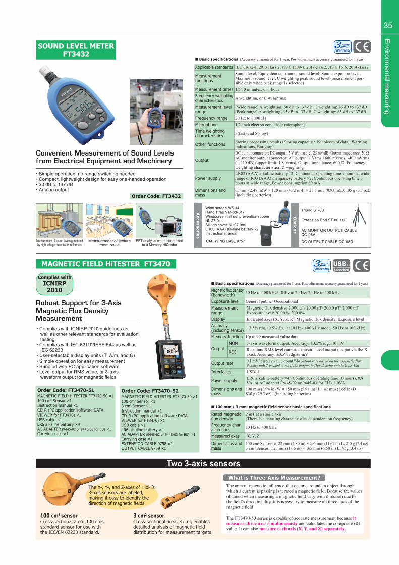
Environmental m
easuring
35
■ Basic specifications (Accuracy guaranteed for 1 year, Post-adjustment accuracy guaranteed for 1 year)
Applicable standards IEC 61672-1: 2013 class 2, JIS C 1509-1: 2017 class2, JIS C 1516: 2014 class2
Measurement functions
Sound level, Equivalent continuous sound level, Sound exposure level, Maximum sound level, C weighting peak sound level (measurement pos-sible only when peak range is selected)
Measurement times 1/5/10 minutes, or 1 hourFrequency weighting characteristics A weighting, or C weighting
Measurement level range
[Wide range] A weighting: 30 dB to 137 dB, C weighting: 36 dB to 137 dB[Peak range] A weighting: 65 dB to 137 dB, C weighting: 65 dB to 137 dB
Frequency range 20 Hz to 8000 HzMicrophone 1/2-inch electret condenser microphoneTime weighting characteristics F(fast) and S(slow)
Other functions Storing processing results (Storing capacity : 199 pieces of data), Warning indications, Bar graph
Output
DC output connector: DC output: 3 V (full scale), 25 mV/dB, Output impedance: 50 ΩAC monitor output connector: AC output: 1 Vrms +600 mVrms, -400 mVrms (at 110 dB) (upper limit: 1.8 Vrms), Output impedance: 600 Ω, Frequency weighting characteristics: Z weighting
Power supplyLR03 (AAA) alkaline battery ×2, Continuous operating time 9 hours at wide range or R03 (AAA) manganese battery ×2, Continuous operating time 3 hours at wide range, Power consumption 80 mA
Dimensions and mass
63 mm (2.48 in)W × 120 mm (4.72 in)H × 23.5 mm (0.93 in)D, 105 g (3.7 oz), (including batteries)
Convenient Measurement of Sound Levels from Electrical Equipment and Machinery
• Simple operation, no range switching needed• Compact, lightweight design for easy one-handed operation• 30 dB to 137 dB• Analog output
SOUND LEVEL METER FT3432
CARRYING CASE 9757
Wind screen WS-14Hand strap VM-63-017Windscreen fall out prevention rubber NL-27-014Silicon cover NL-27-089LR03 (AAA) alkaline battery ×2Instruction manual
Accessories
Options
Tripod ST-80
AC MONITOR OUTPUT CABLE CC-98A
DC OUTPUT CABLE CC-98D
Extension Rod ST-80-100
Order Code: FT3432
Two 3-axis sensors
Cross-sectional area: 3 cm2, enables detailed analysis of magnetic field distribution for measurement targets.
3 cm2 sensor100 cm2 sensorCross-sectional area: 100 cm2, standard sensor for use with the IEC/EN 62233 standard.
The X-, Y-, and Z-axes of Hioki’s 3-axis sensors are labeled, making it easy to identify the direction of magnetic fields.
The area of magnetic influence that occurs around an object through which a current is passing is termed a magnetic field. Because the values obtained when measuring a magnetic field vary with direction due to the field’s directionality, it is necessary to measure all three axes of the magnetic field.
The FT3470-50 series is capable of accurate measurement because it measures three axes simultaneously and calculates the composite (R) value. It can also measure each axis (X, Y, and Z) separately.
What is Three-Axis Measurement?
■ Basic specifications (Accuracy guaranteed for 1 year, Post-adjustment accuracy guaranteed for 1 year)
Magnetic flux density(bandwidth) 10 Hz to 400 kHz/ 10 Hz to 2 kHz/ 2 kHz to 400 kHz
Exposure level General public/ OccupationalMeasurement range
Magnetic flux density: 2.000 μT/ 20.00 μT/ 200.0 μT/ 2.000 mTExposure level: 20.00%/ 200.0%
Display Indicated axes (X, Y, Z, R), Magnetic flux density, Exposure levelAccuracy(including sensor) ±3.5% rdg.±0.5% f.s. (at 10 Hz - 400 kHz mode: 50 Hz to 100 kHz)
Memory function Up to 99 measured value data
OutputMON 3-axis waveform output, Accuracy: ±3.5% rdg.±10 mV
REC Resultant RMS level output/ exposure level output (output via the X-axis), Accuracy: ±3.5% rdg.±3 mV
Output rate 0.1 mV/ display value count *An output rate based on the magnetic flux density unit T is used, even if the magnetic flux density unit is G or A/m
Interfaces USB1.1
Power supply LR6 alkaline battery ×4 (Continuous operating time 10 hours), 0.8 VA, or AC adapter (9445-02 or 9445-03 for EU), 1.0VA
Dimensions and mass
100 mm (3.94 in) W × 150 mm (5.91 in) H × 42 mm (1.65 in) D830 g (29.3 oz), (including batteries)
■ 100 mm2/ 3 mm2 magnetic field sensor basic specifications
Rated magnetic flux density
2 mT at a single axis(There is a derating characteristics dependent on frequency)
Frequency char-acteristics 10 Hz to 400 kHz
Measured axes X, Y, Z
Dimensions and mass
100 cm2 Sensor: φ122 mm (4.80 in) × 295 mm (11.61 in) L, 210 g (7.4 oz)3 cm2 Sensor: □27 mm (1.06 in) × 165 mm (6.50 in) L, 95g (3.4 oz)
Robust Support for 3-Axis Magnetic Flux Density Measurement• Complies with ICNIRP 2010 guidelines as well as other relevant standards for evaluation testing• Complies with IEC 62110/IEEE 644 as well as IEC 62233• User-selectable display units (T, A/m, and G)• Simple operation for easy measurement• Bundled with PC application software• Level output for RMS value, or 3-axis waveform output for magnetic fields
MAGNETIC FIELD HiTESTER FT3470
Complies withICNIRP
2010
Order Code: FT3470-51MAGNETIC FIELD HiTESTER FT3470-50 ×1100 cm2 Sensor ×1Instruction manual ×1CD-R (PC application software DATA VIEWER for FT3470) ×1USB cable ×1LR6 alkaline battery ×4AC ADAPTER (9445-02 or 9445-03 for EU) ×1 Carrying case ×1
Order Code: FT3470-52MAGNETIC FIELD HiTESTER FT3470-50 ×1100 cm2 Sensor ×13 cm2 Sensor ×1Instruction manual ×1CD-R (PC application software DATA VIEWER for FT3470) ×1USB cable ×1LR6 alkaline battery ×4AC ADAPTER (9445-02 or 9445-03 for EU) ×1Carrying case ×1EXTENSION CABLE 9758 ×1OUTPUT CABLE 9759 ×1
Measurement of sound levels generated by high-voltage electrical transformers
Measurement of lecture room noise
FFT analysis when connected to a Memory HiCorder
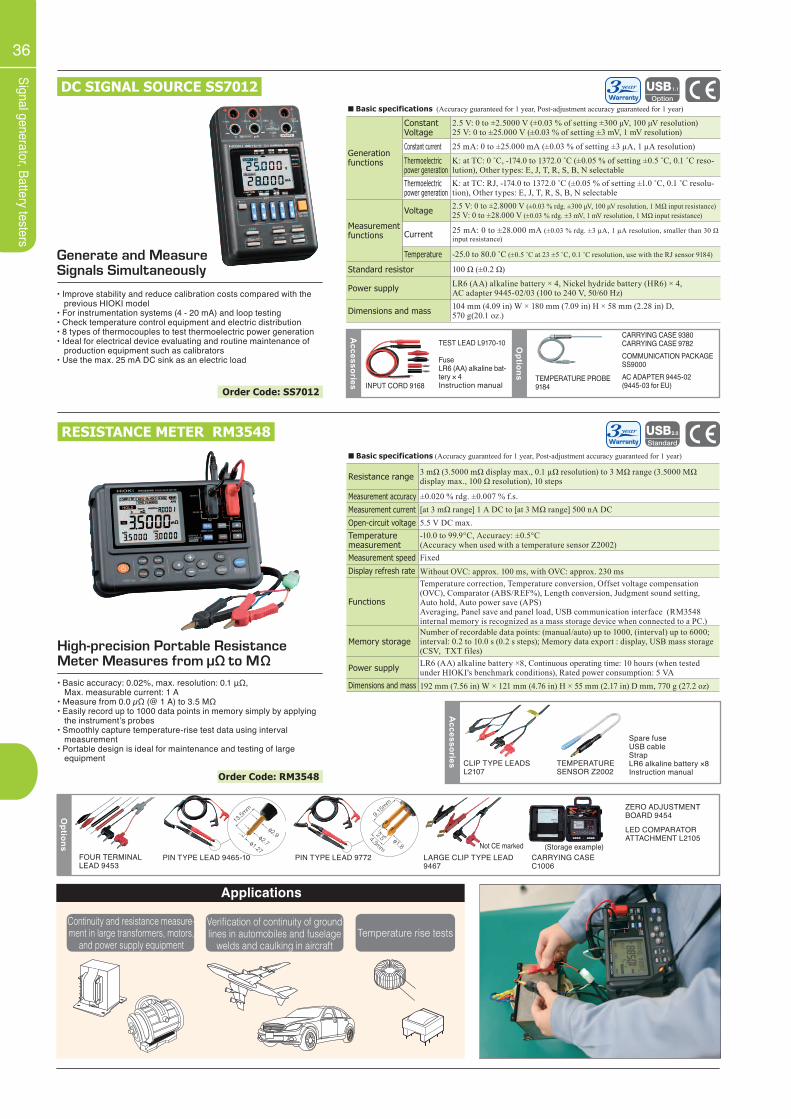
36
Signal generator, Battery testers
DC SIGNAL SOURCE SS7012
■ Basic specifications (Accuracy guaranteed for 1 year, Post-adjustment accuracy guaranteed for 1 year)
Resistance range 3 mΩ (3.5000 mΩ display max., 0.1 µΩ resolution) to 3 MΩ range (3.5000 MΩ display max., 100 Ω resolution), 10 steps
Measurement accuracy ±0.020 % rdg. ±0.007 % f.s.Measurement current [at 3 mΩ range] 1 A DC to [at 3 MΩ range] 500 nA DCOpen-circuit voltage 5.5 V DC max.Temperature measurement
-10.0 to 99.9°C, Accuracy: ±0.5°C (Accuracy when used with a temperature sensor Z2002)
Measurement speed FixedDisplay refresh rate Without OVC: approx. 100 ms, with OVC: approx. 230 ms
Functions
Temperature correction, Temperature conversion, Offset voltage compensation (OVC), Comparator (ABS/REF%), Length conversion, Judgment sound setting, Auto hold, Auto power save (APS)Averaging, Panel save and panel load, USB communication interface (RM3548 internal memory is recognized as a mass storage device when connected to a PC.)
Memory storageNumber of recordable data points: (manual/auto) up to 1000, (interval) up to 6000; interval: 0.2 to 10.0 s (0.2 s steps); Memory data export : display, USB mass storage (CSV, TXT files)
Power supply LR6 (AA) alkaline battery ×8, Continuous operating time: 10 hours (when tested under HIOKI's benchmark conditions), Rated power consumption: 5 VA
Dimensions and mass 192 mm (7.56 in) W × 121 mm (4.76 in) H × 55 mm (2.17 in) D mm, 770 g (27.2 oz)
Generate and Measure Signals Simultaneously
• Improve stability and reduce calibration costs compared with the previous HIOKI model• For instrumentation systems (4 - 20 mA) and loop testing• Check temperature control equipment and electric distribution• 8 types of thermocouples to test thermoelectric power generation• Ideal for electrical device evaluating and routine maintenance of production equipment such as calibrators• Use the max. 25 mA DC sink as an electric load
RESISTANCE METER RM3548
High-precision Portable Resistance Meter Measures from μΩ to MΩ• Basic accuracy: 0.02%, max. resolution: 0.1 μΩ, Max. measurable current: 1 A• Measure from 0.0 µΩ (@ 1 A) to 3.5 MΩ• Easily record up to 1000 data points in memory simply by applying the instrument’s probes• Smoothly capture temperature-rise test data using interval measurement• Portable design is ideal for maintenance and testing of large equipment
Options
FOUR TERMINAL LEAD 9453
PIN TYPE LEAD 9465-10 PIN TYPE LEAD 9772 LARGE CLIP TYPE LEAD 9467
CARRYING CASE C1006
ZERO ADJUSTMENT BOARD 9454
Accessories CLIP TYPE LEADS
L2107TEMPERATURE SENSOR Z2002
Spare fuseUSB cableStrapLR6 alkaline battery ×8Instruction manual
LED COMPARATORATTACHMENT L2105
■ Basic specifications (Accuracy guaranteed for 1 year, Post-adjustment accuracy guaranteed for 1 year)
Generation functions
Constant Voltage
2.5 V: 0 to ±2.5000 V (±0.03 % of setting ±300 μV, 100 μV resolution)25 V: 0 to ±25.000 V (±0.03 % of setting ±3 mV, 1 mV resolution)
Constant current 25 mA: 0 to ±25.000 mA (±0.03 % of setting ±3 μA, 1 μA resolution)
Thermoelectric power generation
K: at TC: 0 ˚C, -174.0 to 1372.0 ˚C (±0.05 % of setting ±0.5 ˚C, 0.1 ˚C reso-lution), Other types: E, J, T, R, S, B, N selectable
Thermoelectric power generation
K: at TC: RJ, -174.0 to 1372.0 ˚C (±0.05 % of setting ±1.0 ˚C, 0.1 ˚C resolu-tion), Other types: E, J, T, R, S, B, N selectable
Measurement functions
Voltage 2.5 V: 0 to ±2.8000 V (±0.03 % rdg. ±300 μV, 100 μV resolution, 1 MΩ input resistance)25 V: 0 to ±28.000 V (±0.03 % rdg. ±3 mV, 1 mV resolution, 1 MΩ input resistance)
Current 25 mA: 0 to ±28.000 mA (±0.03 % rdg. ±3 μA, 1 μA resolution, smaller than 30 Ω input resistance)
Temperature -25.0 to 80.0 ˚C (±0.5 ˚C at 23 ±5 ˚C, 0.1 ˚C resolution, use with the RJ sensor 9184)
Standard resistor 100 Ω (±0.2 Ω)
Power supply LR6 (AA) alkaline battery × 4, Nickel hydride battery (HR6) × 4, AC adapter 9445-02/03 (100 to 240 V, 50/60 Hz)
Dimensions and mass 104 mm (4.09 in) W × 180 mm (7.09 in) H × 58 mm (2.28 in) D,570 g(20.1 oz.)
Options TEMPERATURE PROBE
9184
CARRYING CASE 9380CARRYING CASE 9782COMMUNICATION PACKAGESS9000AC ADAPTER 9445-02(9445-03 for EU)INPUT CORD 9168
TEST LEAD L9170-10
Fuse LR6 (AA) alkaline bat-tery × 4Instruction manual
Accessories
(Storage example)
Applications
Continuity and resistance measure-ment in large transformers, motors,
and power supply equipment
Verification of continuity of ground lines in automobiles and fuselage
welds and caulking in aircraftTemperature rise tests
Not CE marked
Order Code: SS7012
Order Code: RM3548
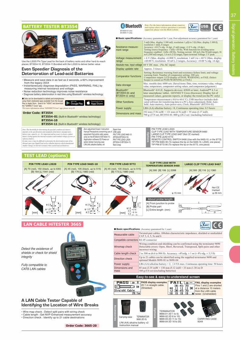
37
Signal generator, Battery testers
PIN TYPE LEAD L2020 PIN TYPE LEAD 9465-10 PIN TYPE LEAD 9772 CLIP TYPE LEAD WITH TEMPERATURE SENSOR 9460 LARGE CLIP TYPE LEAD 9467
[A] 70 (red), 150 (black, up to 630)[B] 164 [L] 1941 (red)
[A] 45 (red), 105 (black, up to 515)[B] 176 [L] 1883 (red)
[A] 45 (red), 105 (black, up to 515)[B] 173 [L] 1880 (red) [A] 300 [B] 106 [L] 2268 [A] 300 [B] 116 [L] 1360
■ Basic specifications (Accuracy guaranteed for 1 year, Post-adjustment accuracy guaranteed for 1 year)
Resistance measure-ment range
3 mΩ (Max. display 3.100 mΩ, resolution 1 μΩ) to 3 Ω (Max. display 3.100 Ω, resolution 1 mΩ), 4 rangesAccuracy: ±0.8 % rdg. ±6 dgt. (3 mΩ range: ±1.0 % rdg. ±8 dgt.)Testing source frequency: 1 kHz ±30 Hz, With function for avoiding noisefrequency enabled: 1 kHz ±80 Hz, Testing current: 160 mA (3m/30 mΩ range), 16 mA (300 mΩ range), 1.6 mA (3 Ω range), Open terminal Voltage: 5 V peak
Voltage measurement range
± 6 V (Max. display ±6.000 V, resolution: 1 mV) to ± 60 V (Max. display ±60.00 V, resolution: 10 mV), 2 ranges, Accuracy: ±0.08 % rdg. ±6 dgt.
Absolute max. input voltage 60 V DC max. (No AC input)Display update rate Approx. 3 times/s
Comparator functionsSetting: Resistance warning limit and resistance failure limit, and voltage warning limit, Number of comparator setting: 200 setsComparator output: LCD display of PASS, WARNING, or FAIL (Select beeper to sound on PASS/WARNING or FAIL)
Data storage Max. storable data: 6000 sets. (Saved items: Date, time, resistance value, voltage value, temperature, comparator setting values, and comparator judgement.)
Bluetooth®
(BT3554-01 and BT3554-11 only)
Bluetooth® 4.0 LE, Supports devices: iOS10 or later, Android™ 4.3 or later smartphone/ tablet, GENNECT Cross (freeware): Display list of measured values, generate reports, or display the trend (on the PC only)
Other functionsTemperature measurement (-10.0 to 60.0 °C), USB interface (includes dedi-cated software for transferring data to a PC), Zero-adjustment, Hold, Auto-hold, Auto-memory, Auto-power-save, Clock, Bluetooth® (BT3554-01)
Power supply LR6 (AA) alkaline battery ×8, Continuous operating time: 8.5 hours
Dimensions and mass 192 mm (7.56 in)W × 121 mm (4.76 in)H × 55 mm (2.17 in)D,790 g (27.9 oz), BT3554-01: 800 g (28.2 oz) (including batteries)
BATTERY TESTER BT3554
Even Speedier Diagnosis of the Deterioration of Lead-acid Batteries• Measure and save data in as fast as 2 seconds, a 60% improvement from the legacy 3554• Instantaneously diagnose degradation (PASS, WARNING, FAIL) by measuring internal resistance and voltage• Noise reduction technology improves noise resistance• Diagnose battery deterioration in real time using Bluetooth® wireless technology
TEST LEAD (options)
BT3554-01 andBT3554-11 only
Note: For the latest information about countries and regions where wireless operation is currently supported, please visit the Hioki website.
13.5
φ 2.7 1
φ 1.27
φ 2.9
Not CE marked
Order Code: BT3554 BT3554-01 (Built-in Bluetooth® wireless technology) BT3554-10 BT3554-11 (Built-in Bluetooth® wireless technology)
Options
Accessories
Zero adjustment board Instruction manual Precautions concerning use of equipment that emits radio waves(only for the BT3554-01/BT3554-11) Application software CD Power-on option sticker Carrying caseLR6 (AA) alkaline battery ×8
PIN TYPE LEAD L2020CLIP TYPE LEAD WITH TEMPERATURE SENSOR 9460LARGE CLIP TYPE LEAD 9467 (Not CE marked)PIN TYPE LEAD 9772REMOTE CONTROL SWITCH 9466 (Use with the 9465-10, or the 9772)TIP PIN 9465-90 (To replace the tip on the 9465-10, L2020, one piece)TIP PIN 9772-90 (To replace the tip on the 9772, one piece)
Note: The thresholds for determining the pass/fail condition of a battery depends on the specifications and standards of the battery manufacturer, battery type, capacity, etc. It is important and necessary to always conduct battery testing against the internal resistance and terminal voltage of a new or reference battery.In some cases, it may be difficult to determine the deterioration state of tra-ditional open type (liquid) lead-acid or alkaline batteries which demonstrate smaller changes in internal resistance than sealed lead acid batteries.
Spare fuseUSB cablePIN TYPE LEAD 9465-10 (BT3554/BT3554-10)PIN TYPE LEAD L2020 (BT3554-01/BT3554-11)Neck strap
■ Data can be downloaded to tablets and smartphonesusing Hioki’s dedicated apps available from the GooglePlay or Apple Store. Search for “HIOKI” and downloadthe “GENNECT Cross” app.*For more information about "GENNECT Cross" app, please see p.10
φ 15 mm φ 29 mm
■ Basic specifications (Accuracy guaranteed for 1 year)
Measurable cable Twisted-pair cables, 100ohm characteristic impedance, shielded or unshieldedCAT 3, 4, 5, 5e and 6
Compatible connectors RJ-45 connector
Wiremap checkWiring condition and shielding can be confirmed using the terminator 9690Detectable errors: Open, Short, Reversed, Transposed, Split pairs and other incorrect wiring
Cable length check 2 to 300 m (6.6 to 984 ft) Accuracy: ±4%rdg. ± 1 m (± 4% rdg. ± 3.3 ft)
Direction check Up to 21 cables can be identified using the supplied terminator 9690 and optional Models 9690-01 to 9690-04
Power supply LR6 (AA) alkaline battery × 2, 1.4 VA max. Continuous operating time: 50 hoursDimensions and mass
85 mm (3.35 in)W × 130 mm (5.12 in)H × 33 mm (1.30 in) D160 g (5.6 oz) (excluding batteries)
Detect the existence ofshields or check for shield integrity
Fully compatible toCAT6 LAN cables
PASS display examples20.1 m straight cable.(Shielded)
FAIL display examplesPins 1 and 2 are shorted at a distance 10 meters from the LAN cable tester. (Unshielded)
Easy-to-see & easy-to-understand screen
LAN CABLE HiTESTER 3665
A LAN Cable Tester Capable of Identifying the Location of Wire Breaks• Wire map check : Detect split pairs with wiring check• Cable length : Get NVP-Enhanced measurement accuracy• Direction check : Identify up to 21 cable destinations
Options
TERMINATOR9690-01 (ID 1 to 5)9690-02 (ID 6 to 10) 9690-03 (ID 11 to 15)9690-04 (ID 16 to 20)
CARRYING CASE 9249
Accessories Carrying case TERMINATOR
9690 (ID 0)LR6 (AA) alkaline battery ×2Instruction manualOrder Code: 3665-20
About probe length[A] From junction to probe [B] Probe part[L] Entire length (mm)
[mm][mm]
13.5
φ 2.7 1
φ 1.27
φ 2.9
[mm]
9.15
4.32.5
φ1.8
Use the L2020 Pin Type Lead for the back of battery racks and other hard-to-reachplaces; BT3554-10, BT3554-11:Bundled with the L2020 to deliver better value
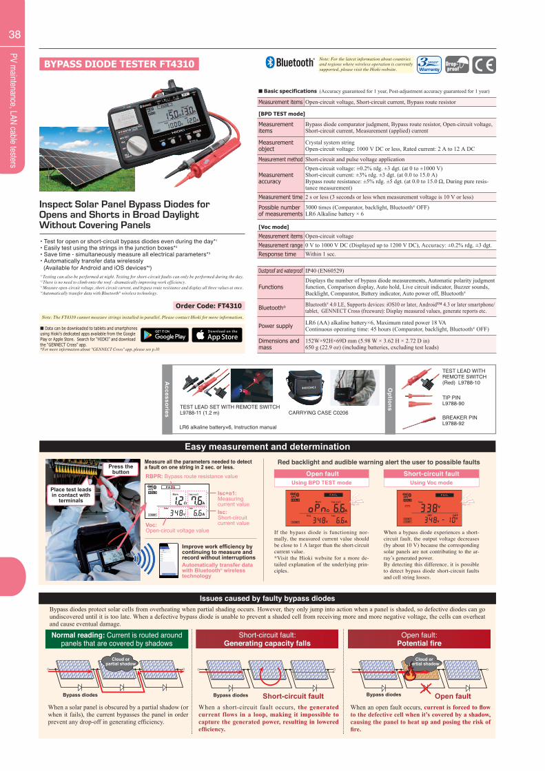
38
PV maintenance, LAN cable testers
Order Code: FT4310
Inspect Solar Panel Bypass Diodes for Opens and Shorts in Broad Daylight Without Covering Panels
BYPASS DIODE TESTER FT4310
Note: The FT4310 cannot measure strings installed in parallel. Please contact Hioki for more information.
• Test for open or short-circuit bypass diodes even during the day*1
• Easily test using the strings in the junction boxes*2
• Save time - simultaneously measure all electrical parameters*3
• Automatically transfer data wirelessly (Available for Android and iOS devices*4)*1 Testing can also be performed at night. Testing for short-circuit faults can only be performed during the day.*2 There is no need to climb onto the roof - dramatically improving work efficiency.*3 Measure open-circuit voltage, short-circuit current, and bypass route resistance and display all three values at once.*4Automatically transfer data with Bluetooth® wireless technology.
■ Basic specifications (Accuracy guaranteed for 1 year, Post-adjustment accuracy guaranteed for 1 year)
Measurement items Open-circuit voltage, Short-circuit current, Bypass route resistor
[BPD TEST mode]
Measurement items
Bypass diode comparator judgment, Bypass route resistor, Open-circuit voltage, Short-circuit current, Measurement (applied) current
Measurement object
Crystal system stringOpen-circuit voltage: 1000 V DC or less, Rated current: 2 A to 12 A DC
Measurement method Short-circuit and pulse voltage application
Measurement accuracy
Open-circuit voltage: ±0.2% rdg. ±3 dgt. (at 0 to ±1000 V)Short-circuit current: ±3% rdg. ±3 dgt. (at 0.0 to 15.0 A)Bypass route resistance: ±5% rdg. ±5 dgt. (at 0.0 to 15.0 Ω, During pure resis-tance measurement)
Measurement time 2 s or less (3 seconds or less when measurement voltage is 10 V or less)
Possible number of measurements
3000 times (Comparator, backlight, Bluetooth® OFF) LR6 Alkaline battery × 6
[Voc mode]
Measurement items Open-circuit voltageMeasurement range 0 V to 1000 V DC (Displayed up to 1200 V DC), Accuracy: ±0.2% rdg. ±3 dgt.Response time Within 1 sec.
Dustproof and waterproof IP40 (EN60529)
FunctionsDisplays the number of bypass diode measurements, Automatic polarity judgment function, Comparison display, Auto hold, Live circuit indicator, Buzzer sounds, Backlight, Comparator, Battery indicator, Auto power off, Bluetooth®
Bluetooth® Bluetooth® 4.0 LE, Supports devices: iOS10 or later, Android™ 4.3 or later smartphone/ tablet, GENNECT Cross (freeware): Display measured values, generate reports etc.
Power supply LR6 (AA) alkaline battery×6, Maximum rated power 18 VAContinuous operating time: 45 hours (Comparator, backlight, Bluetooth® OFF)
Dimensions and mass
152W×92H×69D mm (5.98 W × 3.62 H × 2.72 D in)650 g (22.9 oz) (including batteries, excluding test leads)
LR6 alkaline battery×6, Instruction manual
Accessories
Options
CARRYING CASE C0206
TEST LEAD WITH REMOTE SWITCH (Red) L9788-10
TIP PINL9788-90
BREAKER PINL9788-92
Note: For the latest information about countries and regions where wireless operation is currently supported, please visit the Hioki website.
Short-circuit fault:Generating capacity falls
Bypass diodes
Bypass diodes
Bypass diodes
Bypass diodes
Cloud orpartial shadow
Cloud orpartial shadow
When a short-circuit fault occurs, the generated current flows in a loop, making it impossible to capture the generated power, resulting in lowered efficiency.
Normal reading: Current is routed around panels that are covered by shadows
Bypass diodes
Bypass diodes
Bypass diodes
Bypass diodes
Cloud orpartial shadow
Cloud orpartial shadow
When a solar panel is obscured by a partial shadow (or when it fails), the current bypasses the panel in order prevent any drop-off in generating efficiency.
Open fault:Potential fire
Bypass diodes
Bypass diodes
Bypass diodes
Bypass diodes
Cloud orpartial shadow
Cloud orpartial shadow
When an open fault occurs, current is forced to flow to the defective cell when it’s covered by a shadow, causing the panel to heat up and posing the risk of fire.
Short-circuit fault Open fault
Issues caused by faulty bypass diodes
Easy measurement and determination
Place test leads in contact with
terminals
Press the button
Measure all the parameters needed to detect a fault on one string in 2 sec. or less.
V
A
AVoc
COMP
RBPR
APS PASS
Isc+α1:Measuring current valueIsc:Short-circuit current valueVoc:
Open-circuit voltage value
RBPR: Bypass route resistance value
V
A
AVoc
COMP
RBPR
APS FAIL
V
VV
Voc
DIFFREF
COMPCONT
APS FAIL
Red backlight and audible warning alert the user to possible faults
Open fault Short-circuit faultUsing BPD TEST mode Using Voc mode
If the bypass diode is functioning nor-mally, the measured current value should be close to 1 A larger than the short-circuit current value. *Visit the Hioki website for a more de-tailed explanation of the underlying prin-ciples.
When a bypass diode experiences a short-circuit fault, the output voltage decreases (by about 10 V) because the corresponding solar panels are not contributing to the ar-ray’s generated power. By detecting this difference, it is possible to detect bypass diode short-circuit faults and cell string losses.
Bypass diodes protect solar cells from overheating when partial shading occurs. However, they only jump into action when a panel is shaded, so defective diodes can go undiscovered until it is too late. When a defective bypass diode is unable to prevent a shaded cell from receiving more and more negative voltage, the cells can overheat and cause eventual damage.
Improve work efficiency by continuing to measure and record without interruptionsAutomatically transfer data with Bluetooth® wireless technology
TEST LEAD SET WITH REMOTE SWITCHL9788-11 (1.2 m)
■ Data can be downloaded to tablets and smartphonesusing Hioki’s dedicated apps available from the GooglePlay or Apple Store. Search for “HIOKI” and downloadthe “GENNECT Cross” app.*For more information about "GENNECT Cross" app, please see p.10
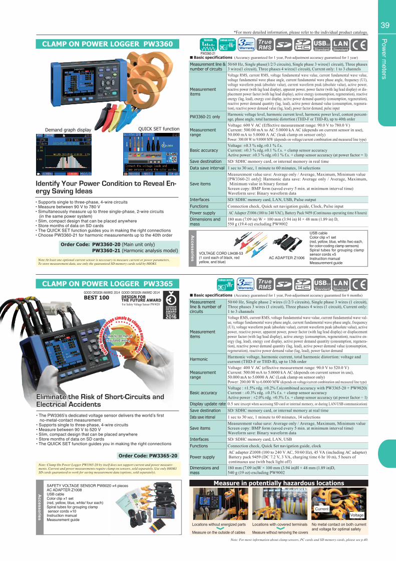
Power m
eters
39
Safely m
easu
re vo
ltage simply by clipping onto cables
6 mm to 30 mm of insulated wiring
CLAMP ON POWER LOGGER PW3360
CLAMP ON POWER LOGGER PW3365
Note:At least one optional current sensor is necessary to measure current or power parameters. To store measurement data, use only the guaranteed SD memory cards sold by HIOKI.
Note: For more information about clamp sensors, PC cards and SD memory cards, please see p.40.
■ Basic specifications (Accuracy guaranteed for 1 year, Post-adjustment accuracy guaranteed for 1 year)
Measurement line & number of circuits
50/60 Hz, Single phase(1/2/3 circuits), Single phase 3 wires(1 circuit), Three phases 3 wires(1 circuit), Three phases 4 wires(1 circuit), Current only: 1 to 3 channels
Measurement items
Voltage RMS, current RMS, voltage fundamental wave value, current fundamental wave value, voltage fundamental wave phase angle, current fundamental wave phase angle, frequency (U1), voltage waveform peak (absolute value), current waveform peak (absolute value), active power, reactive power (with lag/lead display), apparent power, power factor (with lag/lead display) or dis-placement power factor (with lag/lead display), active energy (consumption, regeneration), reactive energy (lag, lead), energy cost display, active power demand quantity (consumption, regeneration), reactive power demand quantity (lag, lead), active power demand value (consumption, regenera-tion), reactive power demand value (lag, lead), power factor demand, pulse input
PW3360-21 only Harmonic voltage level, harmonic current level, harmonic power level, content percent-age, phase angle, total harmonic distortion (THD-F or THD-R), up to 40th order
Measurement range
Voltage: 600 V AC (Effective measurement range: 90.0 V to 780.0 V)Current: 500.00 mA to AC 5.0000 kA AC (depends on current sensor in use),50.000 mA to 5.0000 A AC (leak clamp on sensor only)Power: 300.00 W to 9.0000 MW (depends on voltage/current combination and measured line type)
Basic accuracyVoltage: ±0.3 % rdg.±0.1 % f.s. Current: ±0.3 % rdg.±0.1 % f.s. + clamp sensor accuracyActive power: ±0.3 % rdg.±0.1 % f.s. + clamp sensor accuracy (at power factor = 1)
Save destination SD/ SDHC memory card, or internal memory in real timeData save interval 1 sec to 30 sec, 1 minute to 60 minutes, 14 selections
Save items
Measurement value save: Average only / Average, Maximum, Minimum value[PW3360-21 only]: Harmonic data save: Average only / Average, Maximum, Minimum value in binary format
Screen copy: BMP form (saved every 5 min. at minimum interval time)Waveform save: Binary waveform data
Interfaces SD/ SDHC memory card, LAN, USB, Pulse outputFunctions Connection check, Quick set navigation guide, Clock, Pulse inputPower supply AC Adapter Z1006 (100 to 240 VAC), Battery Pack 9459 (Continuous operating time 8 hours)Dimensions and mass
180 mm (7.09 in) W × 100 mm (3.94 in) H × 48 mm (1.89 in) D,550 g (19.4 oz) excluding PW9002
Accessories
VOLTAGE CORD L9438-53(1 cord each of black, red yellow, and blue)
USB cableColor clip ×1 set(red, yellow, blue, white /two each, for color-coding clamp sensors)Spiral tubes for grouping clamp sensor cords ×5Instruction manualMeasurement guide
AC ADAPTER Z1006
QUICK SET function
Identify Your Power Condition to Reveal En-ergy Saving Ideas• Supports single to three-phase, 4-wire circuits• Measure between 90 V to 780 V• Simultaneously measure up to three single-phase, 2-wire circuits (in the same power system)• Slim, compact design that can be placed anywhere• Store months of data on SD cards• The QUICK SET function guides you in making the right connections• Choose PW3360-21 for harmonic measurements up to the 40th order
Order Code: PW3360-20 (Main unit only) PW3360-21 (Harmonic analysis model)
*For more detailed information, please refer to the individual product catalogs.
Demand graph display
Note: Clamp On Power Logger PW3365-20 by itself does not support current and power measure-ments. Current and power measurements require clamp on sensors, sold separately. Use only HIOKI SD cards guaranteed to work for saving measurement data (options, sold separately).
Eliminate the Risk of Short-Circuits and Electrical Accidents• The PW3365’s dedicated voltage sensor delivers the world’s first no-metal-contact measurement• Supports single to three-phase, 4-wire circuits• Measure between 90 V to 520 V• Slim, compact design that can be placed anywhere• Store months of data on SD cards• The QUICK SET function guides you in making the right connections
Order Code: PW3365-20
No metal contact on both current and voltage for optimal safety
Measure in potentially hazardous locations
CurrentVoltage
Locations without energized parts
Measure on the outside of cables
Locations with covered terminals
Measure without removing the covers
■ Basic specifications (Accuracy guaranteed for 1 year, Post-adjustment accuracy guaranteed for 6 months)
Measurement line & number of circuits
50/60 Hz, Single phase 2 wires (1/2/3 circuits), Single phase 3 wires (1 circuit), Three phases 3 wires (1 circuit), Three phases 4 wires (1 circuit), Current only: 1 to 3 channels
Measurement items
Voltage RMS, current RMS, voltage fundamental wave value, current fundamental wave val-ue, voltage fundamental wave phase angle, current fundamental wave phase angle, frequency (U1), voltage waveform peak (absolute value), current waveform peak (absolute value), active power, reactive power, apparent power, power factor (with lag/lead display) or displacement power factor (with lag/lead display), active energy (consumption, regeneration), reactive en-ergy (lag, lead), energy cost display, active power demand quantity (consumption, regenera-tion), reactive power demand quantity (lag, lead), active power demand value (consumption, regeneration), reactive power demand value (lag, lead), power factor demand
Harmonic Harmonic voltage, harmonic current, total harmonic distortion: voltage and current (THD-F or THD-R), up to 13th order
Measurement range
Voltage: 400 V AC (effective measurement range: 90.0 V to 520.0 V)Current: 500.00 mA to 5.0000 kA AC (depends on current sensor in use),50.000 mA to 5.0000 A AC (Leak clamp on sensor only)Power: 200.00 W to 6.0000 MW (depends on voltage/current combination and measured line type)
Basic accuracyVoltage : ±1.5% rdg. ±0.2% f.s(combined accuracy with PW3365-20 + PW9020)Current : ±0.3% rdg. ±0.1% f.s. + clamp sensor accuracyActive power : ±2.0% rdg. ±0.3% f.s. + clamp sensor accuracy (at power factor = 1)
Display update rate 0.5 sec (except when accessing SD card or internal memory, or during LAN/USB communication)
Save destination SD/ SDHC memory card, or internal memory at real timeData save interval 1 sec to 30 sec, 1 minute to 60 minutes, 14 selections
Save itemsMeasurement value save: Average only / Average, Maximum, Minimum valueScreen copy: BMP form (saved every 5 min. at minimum interval time)Waveform save: Binary waveform data
Interfaces SD/ SDHC memory card, LAN, USBFunctions Connection check, Quick Set navigation guide, clock
Power supplyAC adapter Z1008 (100 to 240 V AC, 50/60 Hz), 45 VA (including AC adapter)Battery pack 9459 (DC 7.2 V, 3 VA, charging time 6 hr 10 m), 5 hours of continuous use (with back light off)
Dimensions and mass
180 mm (7.09 in)W × 100 mm (3.94 in)H × 48 mm (1.89 in)D,540 g (19 oz) excluding PW9002
Accessories
SAFETY VOLTAGE SENSOR PW9020 ×4 piecesAC ADAPTER Z1008USB cableColor clip ×1 set (red, yellow, blue, white/ four each)Spiral tubes for grouping clamp sensor cords ×10Instruction manualMeasurement guide
GOOD DESIGN AWARD 2014
BEST 100GOOD DESIGN AWARD 2014DESIGN FORTHE FUTURE AWARDFor Safety Voltage Sensor PW9020
PW3360-21
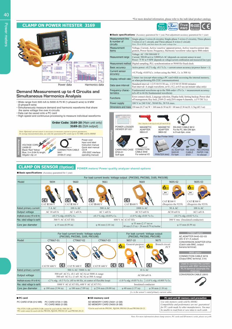
Power m
eters
40*For more detailed information, please refer to the individual product catalogs.
CLAMP ON POWER HiTESTER 3169
• Wide range from 500 mA to 5000 A/75 W (1-phase/2-wire) to 9 MW (3-phase/4-wire)• Simultaneously measure demand and harmonic waveforms that share the same voltage line over 4-circuits• Data can be saved onto a PC card• High-speed and continuous processing to measure individual waveforms
Demand Measurement up to 4 Circuits and Simultaneous Harmonics Analysis
■ Basic specifications (Accuracy guaranteed for 1 year, Post-adjustment accuracy guaranteed for 1 year)
Measurement line & number ofcircuits
Single-phase 2-wires (4 circuits), Single-phase 3-wires (2 circuits), Three-phases 3-wires (2 or 1 circuit), and Three-phases 4-wires (1 circuit) Note: 50 or 60 Hz, and that share the same voltage line
Measurement items
Voltage, Current, Active/ reactive/ apparent power, Active/ reactive power inte-gration, Power factor, Frequency, Harmonic waveform value (up to 40th order)
Measurement rangeVoltage: AC 150/300/600 VCurrent: 500.00 mA to 5.0000 kA AC (depends on current sensor in use)Power: 75 W to 9 MW (depends on voltage/current combination and measured line type)
Measurement method Digital sampling, PLL synchronization or 50/60 Hz fixed clockBasic accuracy Active power: ±0.2 % rdg. ±0.1 % f.s. + current sensor accuracy (at power factor = 1)Current sensor accuracy ±0.3%rdg.±0.01%f.s. (when using the 9661, f.s. is 500 A)
Display refresh rate 2 times /sec (except when using a PC card while accessing the internal memory, or when performing RS-232C communications)
Data save interval Standard interval: 1/2/5/10/15/30 sec, 1/2/5/10/15/30/60 minutesFast interval: A single waveform, or 0.1, 0.2, or 0.5 sec (at instant value only)
Frequency charac-terristics
Fundamental waveforms up to the 50th order ±3% f.s. + measurement accuracy (of a 45 to 66 Hz fundamental waveform)
Functions Error connect check, Language selection, Display hold, Setting backup, Power shut off management, Key lock, [3169-21 only] D/A output 4 channels, (±5 V DC f.s.)
Power supply 100 V to 240 VAC, 50/60 Hz, 30 VA max.Dimensions and mass 210 mm (8.27 in) W × 160 mm (6.30 in) H × 60 mm (2.36 in) D, 1.2 kg (42.3 oz)
Accessories
VOLTAGE CORDL9438-53Black/ Red/ Yellow/ Blue, 3 m (9.84 ft) length, Alligator clip ×4
CONNECTION CABLE 9441(3169-21 only)
Power cordInput cord labelInstruction manual Quick start manual CD-R (RS-232C interface operating manual)
■ PC card ■ SD memory card
PC CARD 9728 (512 MB) SD MEMORY CARD Z4001 (2 GB)SD MEMORY CARD Z4003 (8 GB)
*The 9729 (1 GB) and 9830 (2 GB) cannot be used with the 3169-20/-21.*PC cards cannot be used with the PW3198, PQ3100, PW3365-20 and PW3360-20/-21.
*Can be used with the PW3198, PQ3100, PW3365-20 and PW3360-20/-21.
PC CARD 9729 (1 GB)PC CARD 9830 (2 GB)
PC card and SD memory card precautionUse only memory cards sold by HIOKI. Compatibility and performance are not guaranteed for PC cards made by other manufacturers. You may be unable to read from or save data to such cards.
■ Basic specifications (Accuracy guaranteed for 1 year)
For load current levels: Voltage output (PW3365, PW3360, 3169, PW3198)
Model 9694 9660 9661 9669 9695-02 9695-03
Rated primary current 5 A AC 100 A AC 500 A AC 1000 A AC 50 A AC 100 A ACOutput voltage AC 10 mV/A AC 1 mV/A AC 1 mV/A AC 0.5 mV/A AC10 mV/A AC1 mV/AAmplitude accuracy (45 to 66 Hz) ±0.3 % rdg.±0.02% f.s. ±0.3 % rdg.±0.01% f.s. ±1.0 % rdg.±0.01 % f.s. ±0.3 % rdg.±0.02 % f.s.Max. rated voltage to earth 300 V AC (CAT III) 600 V AC (CAT III) 300 V rms (Insulated conductor)
Core jaw diameter φ 15 mm (0.59 in) φ 46 mm (1.81 in) φ 55 mm (2.17 in) or 80 mm (3.15 in) × 20 mm (0.79 in) busbar φ 15 mm (0.59 in)
CAT III 600 VCAT III 600 VCAT III 300 V CAT III 300 V
f.s. is the sensorʼs rated primary current value.
For load current levels: Voltage output(PW3365, PW3360, 3169, PW3198)
For leak current: Voltage output(PW3365, PW3360, PW3198)
Model CT9667-01 CT9667-02 CT9667-03 9657-10 9675
Rated primary current 500 A AC/ 5000 A AC 10 A AC
Output voltage 500 mV AC/f.s. (0.1 mV AC/A) at 5000 A range500 mV AC/f.s. (1 mV AC/A) at 500 A range AC100 mV/A
Amplitude accuracy (45 to 66 Hz) ±2 % rdg. ±0.3 % f.s. (45 to 66 Hz, at center of flexible loop) ±1.0 % rdg.±0.05 % f.s. ±1.0 % rdg.±0.005 % f.s. Max. rated voltage to earth 1000 V AC (CAT III), 600 V AC (CAT IV) Insulated conductorCore jaw diameter φ 100 mm (3.94 in) φ 180 mm (7.09 in) φ 254 mm (10.00 in) φ 40 mm (1.57 in) φ 30 mm (1.18 in)
General-purpose ZCT
CAT III 300 V(Requires the 9219)
CAT III 300 V(Requires the 9219)
Branch circuit ZCT
AC ADAPTER 9445-02/-03 (DC 9 V/1 A output)CONVERSION ADAPTER 9704(Catch side BNC, output banana terminal)
CONNECTION CABLE 9219(Output BNC terminal, 3 m)
CONVERSION CABLE L9910
CT9667 option
9695 option
Used to connect the current sensors with BNC terminal to PL14 terminal (example the
PQ3100)
CAT IV 600 V CAT IV 600 V CAT IV 600 V
Note: For more information about clamp sensors, PC cards and SD memory cards, please see p.40.
CLAMP ON SENSOR (Option) POWER meters/ Power quality analyzer shared options
Note: Optional current sensor is necessary to measure current or power parameters. To storage measurement data, use only the guaranteed PC cards (up to 512 MB) sold by HIOKI
Order Code: 3169-20 (Main unit only) 3169-21 (D/A output)
CONNECTION CABLE 9440For external I/O
RS-232C CABLE 9612For the PC, Mini DIN 9pin to D-sub 9pin, cross
CARRYING CASE 9720-01Soft type PRINTER 9442
AC ADAPTER 9443-02 EU type
RS-232C CABLE 9721
RECORDING PAPER 119610 rolls/set
Options
POWER LOGGER VIEWER SF1001
For the Printer 9442
MAGNETIC ADAPTER9804-01
MAGNETIC ADAPTER9804-02
Note: Attaches to the tip of cord, φ11 mm (0.43 in)
Harmonics dataPower data
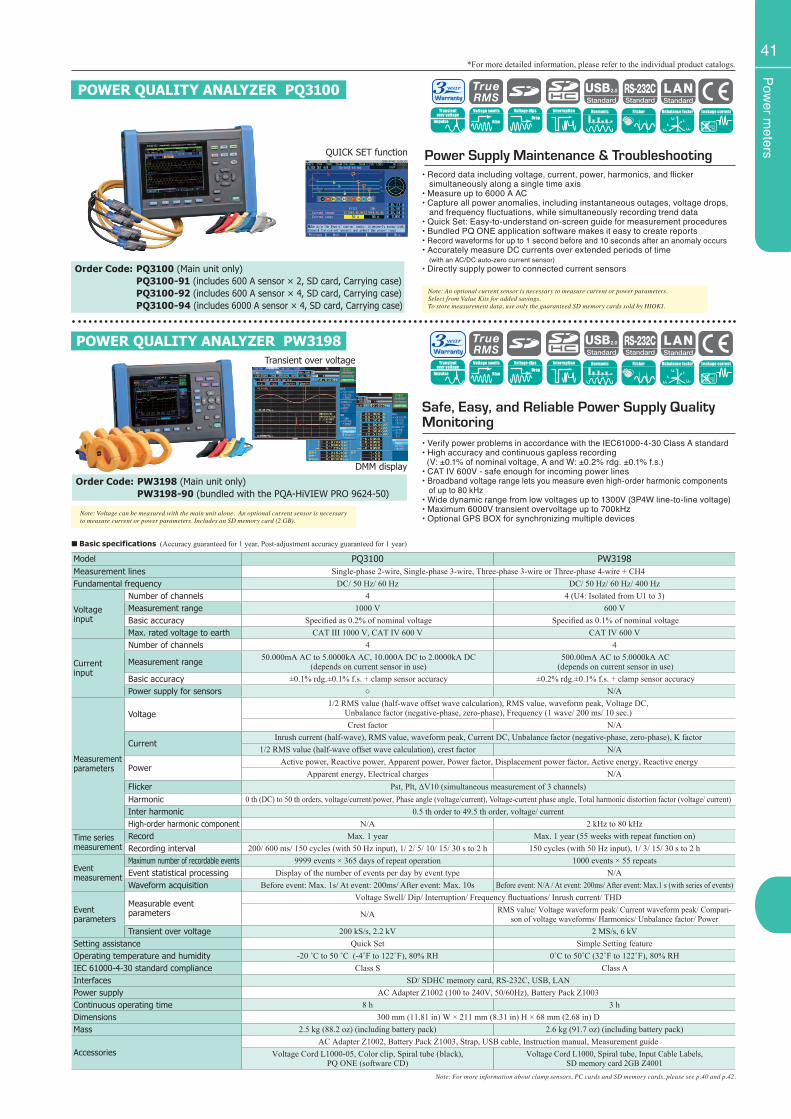
Power m
eters
41
DMM display
Note: For more information about clamp sensors, PC cards and SD memory cards, please see p.40 and p.42.
• Verify power problems in accordance with the IEC61000-4-30 Class A standard• High accuracy and continuous gapless recording (V: ±0.1% of nominal voltage, A and W: ±0.2% rdg. ±0.1% f.s.)• CAT IV 600V - safe enough for incoming power lines• Broadband voltage range lets you measure even high-order harmonic components of up to 80 kHz• Wide dynamic range from low voltages up to 1300V (3P4W line-to-line voltage)• Maximum 6000V transient overvoltage up to 700kHz• Optional GPS BOX for synchronizing multiple devices
Safe, Easy, and Reliable Power Supply Quality Monitoring
Note: Voltage can be measured with the main unit alone. An optional current sensor is necessary to measure current or power parameters. Includes an SD memory card (2 GB).
Order Code: PW3198 (Main unit only) PW3198-90 (bundled with the PQA-HiVIEW PRO 9624-50)
Note: An optional current sensor is necessary to measure current or power parameters. Select from Value Kits for added savings.To store measurement data, use only the guaranteed SD memory cards sold by HIOKI.
Order Code: PQ3100 (Main unit only) PQ3100-91 (includes 600 A sensor × 2, SD card, Carrying case) PQ3100-92 (includes 600 A sensor × 4, SD card, Carrying case) PQ3100-94 (includes 6000 A sensor × 4, SD card, Carrying case)
POWER QUALITY ANALYZER PW3198
QUICK SET function Power Supply Maintenance & Troubleshooting• Record data including voltage, current, power, harmonics, and flicker simultaneously along a single time axis• Measure up to 6000 A AC• Capture all power anomalies, including instantaneous outages, voltage drops, and frequency fluctuations, while simultaneously recording trend data • Quick Set: Easy-to-understand on-screen guide for measurement procedures• Bundled PQ ONE application software makes it easy to create reports• Record waveforms for up to 1 second before and 10 seconds after an anomaly occurs• Accurately measure DC currents over extended periods of time (with an AC/DC auto-zero current sensor)• Directly supply power to connected current sensors
■ Basic specifications (Accuracy guaranteed for 1 year, Post-adjustment accuracy guaranteed for 1 year)
Model PQ3100 PW3198Measurement lines Single-phase 2-wire, Single-phase 3-wire, Three-phase 3-wire or Three-phase 4-wire + CH4Fundamental frequency DC/ 50 Hz/ 60 Hz DC/ 50 Hz/ 60 Hz/ 400 Hz
Voltageinput
Number of channels 4 4 (U4: Isolated from U1 to 3)Measurement range 1000 V 600 VBasic accuracy Specified as 0.2% of nominal voltage Specified as 0.1% of nominal voltageMax. rated voltage to earth CAT III 1000 V, CAT IV 600 V CAT IV 600 V
Current input
Number of channels 4 4
Measurement range 50.000mA AC to 5.0000kA AC, 10.000A DC to 2.0000kA DC(depends on current sensor in use)
500.00mA AC to 5.0000kA AC (depends on current sensor in use)
Basic accuracy ±0.1% rdg.±0.1% f.s. + clamp sensor accuracy ±0.2% rdg.±0.1% f.s. + clamp sensor accuracyPower supply for sensors ○ N/A
Measurement parameters
Voltage1/2 RMS value (half-wave offset wave calculation), RMS value, waveform peak, Voltage DC,
Unbalance factor (negative-phase, zero-phase), Frequency (1 wave/ 200 ms/ 10 sec.)Crest factor N/A
CurrentInrush current (half-wave), RMS value, waveform peak, Current DC, Unbalance factor (negative-phase, zero-phase), K factor
1/2 RMS value (half-wave offset wave calculation), crest factor N/A
Power Active power, Reactive power, Apparent power, Power factor, Displacement power factor, Active energy, Reactive energy
Apparent energy, Electrical charges N/AFlicker Pst, Plt, ΔV10 (simultaneous measurement of 3 channels)Harmonic 0 th (DC) to 50 th orders, voltage/current/power, Phase angle (voltage/current), Voltage-current phase angle, Total harmonic distortion factor (voltage/ current)Inter harmonic 0.5 th order to 49.5 th order, voltage/ currentHigh-order harmonic component N/A 2 kHz to 80 kHz
Time seriesmeasurement
Record Max. 1 year Max. 1 year (55 weeks with repeat function on)Recording interval 200/ 600 ms/ 150 cycles (with 50 Hz input), 1/ 2/ 5/ 10/ 15/ 30 s to 2 h 150 cycles (with 50 Hz input), 1/ 3/ 15/ 30 s to 2 h
Eventmeasurement
Maximum number of recordable events 9999 events × 365 days of repeat operation 1000 events × 55 repeatsEvent statistical processing Display of the number of events per day by event type N/AWaveform acquisition Before event: Max. 1s/ At event: 200ms/ After event: Max. 10s Before event: N/A / At event: 200ms/ After event: Max.1 s (with series of events)
Eventparameters
Measurable eventparameters
Voltage Swell/ Dip/ Interruption/ Frequency fluctuations/ Inrush current/ THD
N/A RMS value/ Voltage waveform peak/ Current waveform peak/ Compari-son of voltage waveforms/ Harmonics/ Unbalance factor/ Power
Transient over voltage 200 kS/s, 2.2 kV 2 MS/s, 6 kVSetting assistance Quick Set Simple Setting featureOperating temperature and humidity -20 ˚C to 50 ˚C (-4˚F to 122˚F), 80% RH 0˚C to 50˚C (32˚F to 122˚F), 80% RHIEC 61000-4-30 standard compliance Class S Class AInterfaces SD/ SDHC memory card, RS-232C, USB, LANPower supply AC Adapter Z1002 (100 to 240V, 50/60Hz), Battery Pack Z1003Continuous operating time 8 h 3 hDimensions 300 mm (11.81 in) W × 211 mm (8.31 in) H × 68 mm (2.68 in) DMass 2.5 kg (88.2 oz) (including battery pack) 2.6 kg (91.7 oz) (including battery pack)
AccessoriesAC Adapter Z1002, Battery Pack Z1003, Strap, USB cable, Instruction manual, Measurement guide
Voltage Cord L1000-05, Color clip, Spiral tube (black),PQ ONE (software CD)
Voltage Cord L1000, Spiral tube, Input Cable Labels, SD memory card 2GB Z4001
POWER QUALITY ANALYZER PQ3100
*For more detailed information, please refer to the individual product catalogs.
Transient over voltage
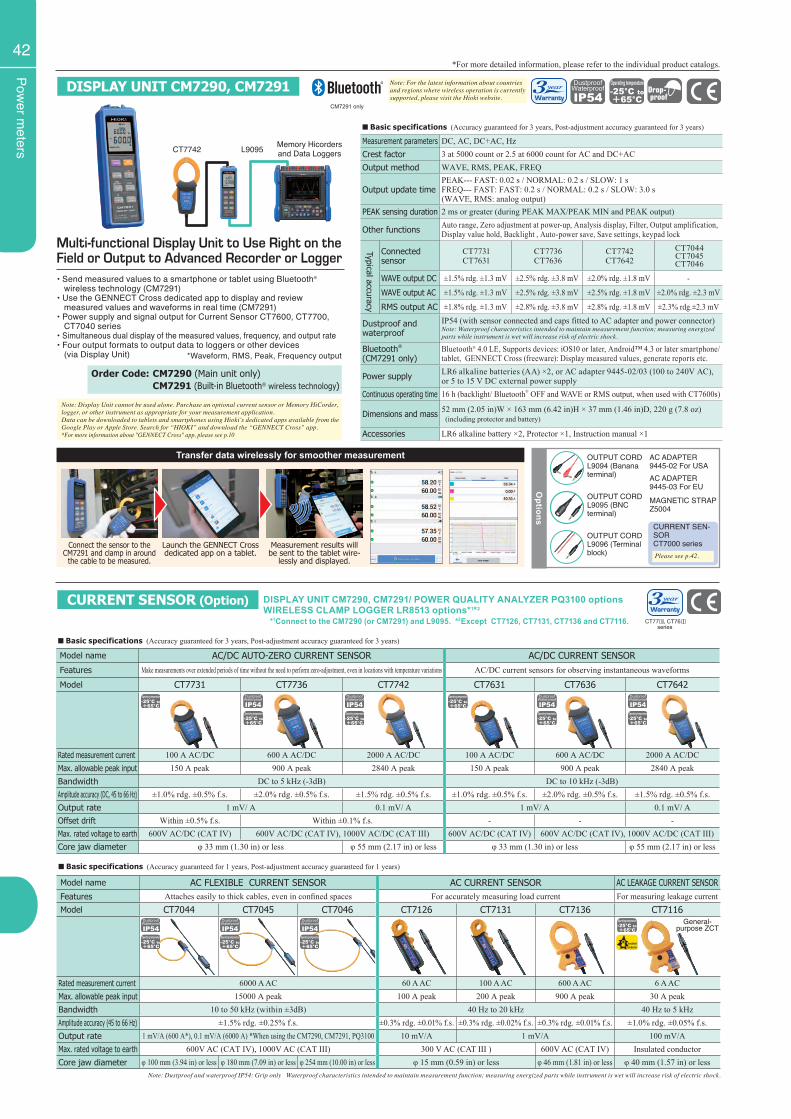
Power m
eters
42
CURRENT SENSOR (Option) DISPLAY UNIT CM7290, CM7291/ POWER QUALITY ANALYZER PQ3100 optionsWIRELESS CLAMP LOGGER LR8513 options*1*2
*1Connect to the CM7290 (or CM7291) and L9095. *2Except CT7126, CT7131, CT7136 and CT7116.
Model name AC FLEXIBLE CURRENT SENSOR AC CURRENT SENSOR AC LEAKAGE CURRENT SENSORFeatures Attaches easily to thick cables, even in confined spaces For accurately measuring load current For measuring leakage currentModel CT7044 CT7045 CT7046 CT7126 CT7131 CT7136 CT7116
Rated measurement current 6000 A AC 60 A AC 100 A AC 600 A AC 6 A ACMax. allowable peak input 15000 A peak 100 A peak 200 A peak 900 A peak 30 A peakBandwidth 10 to 50 kHz (within ±3dB) 40 Hz to 20 kHz 40 Hz to 5 kHzAmplitude accuracy (45 to 66 Hz) ±1.5% rdg. ±0.25% f.s. ±0.3% rdg. ±0.01% f.s. ±0.3% rdg. ±0.02% f.s. ±0.3% rdg. ±0.01% f.s. ±1.0% rdg. ±0.05% f.s.Output rate 1 mV/A (600 A*), 0.1 mV/A (6000 A) *When using the CM7290, CM7291, PQ3100 10 mV/A 1 mV/A 100 mV/AMax. rated voltage to earth 600V AC (CAT IV), 1000V AC (CAT III) 300 V AC (CAT III ) 600V AC (CAT IV) Insulated conductorCore jaw diameter φ 100 mm (3.94 in) or less φ 180 mm (7.09 in) or less φ 254 mm (10.00 in) or less φ 15 mm (0.59 in) or less φ 46 mm (1.81 in) or less φ 40 mm (1.57 in) or less
■ Basic specifications (Accuracy guaranteed for 1 years, Post-adjustment accuracy guaranteed for 1 years)
■ Basic specifications (Accuracy guaranteed for 3 years, Post-adjustment accuracy guaranteed for 3 years)
Model name AC/DC AUTO-ZERO CURRENT SENSOR AC/DC CURRENT SENSORFeatures Make measurements over extended periods of time without the need to perform zero-adjustment, even in locations with temperature variations AC/DC current sensors for observing instantaneous waveforms
Model CT7731 CT7736 CT7742 CT7631 CT7636 CT7642
Rated measurement current 100 A AC/DC 600 A AC/DC 2000 A AC/DC 100 A AC/DC 600 A AC/DC 2000 A AC/DC Max. allowable peak input 150 A peak 900 A peak 2840 A peak 150 A peak 900 A peak 2840 A peakBandwidth DC to 5 kHz (-3dB) DC to 10 kHz (-3dB)Amplitude accuracy (DC, 45 to 66 Hz) ±1.0% rdg. ±0.5% f.s. ±2.0% rdg. ±0.5% f.s. ±1.5% rdg. ±0.5% f.s. ±1.0% rdg. ±0.5% f.s. ±2.0% rdg. ±0.5% f.s. ±1.5% rdg. ±0.5% f.s.Output rate 1 mV/ A 0.1 mV/ A 1 mV/ A 0.1 mV/ AOffset drift Within ±0.5% f.s. Within ±0.1% f.s. - - -Max. rated voltage to earth 600V AC/DC (CAT IV) 600V AC/DC (CAT IV), 1000V AC/DC (CAT III) 600V AC/DC (CAT IV) 600V AC/DC (CAT IV), 1000V AC/DC (CAT III)Core jaw diameter φ 33 mm (1.30 in) or less φ 55 mm (2.17 in) or less φ 33 mm (1.30 in) or less φ 55 mm (2.17 in) or less
Note: Dustproof and waterproof IP54: Grip only Waterproof characteristics intended to maintain measurement function; measuring energized parts while instrument is wet will increase risk of electric shock.
Transfer data wirelessly for smoother measurement
Connect the sensor to the CM7291 and clamp in around
the cable to be measured.
Launch the GENNECT Cross dedicated app on a tablet.
Measurement results will be sent to the tablet wire-
lessly and displayed.
■ Basic specifications (Accuracy guaranteed for 3 years, Post-adjustment accuracy guaranteed for 3 years)
Measurement parameters DC, AC, DC+AC, HzCrest factor 3 at 5000 count or 2.5 at 6000 count for AC and DC+ACOutput method WAVE, RMS, PEAK, FREQ
Output update time PEAK--- FAST: 0.02 s / NORMAL: 0.2 s / SLOW: 1 sFREQ--- FAST: FAST: 0.2 s / NORMAL: 0.2 s / SLOW: 3.0 s(WAVE, RMS: analog output)
PEAK sensing duration 2 ms or greater (during PEAK MAX/PEAK MIN and PEAK output)
Other functions Auto range, Zero adjustment at power-up, Analysis display, Filter, Output amplification, Display value hold, Backlight , Auto-power save, Save settings, keypad lock
Connected sensor
CT7731CT7631
CT7736CT7636
CT7742CT7642
CT7044CT7045CT7046
WAVE output DC ±1.5% rdg. ±1.3 mV ±2.5% rdg. ±3.8 mV ±2.0% rdg. ±1.8 mV -
WAVE output AC ±1.5% rdg. ±1.3 mV ±2.5% rdg. ±3.8 mV ±2.5% rdg. ±1.8 mV ±2.0% rdg. ±2.3 mV
RMS output AC ±1.8% rdg. ±1.3 mV ±2.8% rdg. ±3.8 mV ±2.8% rdg. ±1.8 mV ±2.3% rdg.±2.3 mV
Dustproof andwaterproof
IP54 (with sensor connected and caps fitted to AC adapter and power connector)Note: Waterproof characteristics intended to maintain measurement function; measuring energized parts while instrument is wet will increase risk of electric shock.
Bluetooth®
(CM7291 only)Bluetooth® 4.0 LE, Supports devices: iOS10 or later, Android™ 4.3 or later smartphone/ tablet, GENNECT Cross (freeware): Display measured values, generate reports etc.
Power supply LR6 alkaline batteries (AA) ×2, or AC adapter 9445-02/03 (100 to 240V AC), or 5 to 15 V DC external power supply
Continuous operating time 16 h (backlight/ Bluetooth® OFF and WAVE or RMS output, when used with CT7600s)
Dimensions and mass 52 mm (2.05 in)W × 163 mm (6.42 in)H × 37 mm (1.46 in)D, 220 g (7.8 oz) (including protector and battery)
Accessories LR6 alkaline battery ×2, Protector ×1, Instruction manual ×1
Memory Hicorders and Data LoggersCT7742 L9095
Multi-functional Display Unit to Use Right on the Field or Output to Advanced Recorder or Logger
Options
OUTPUT CORD L9095 (BNC terminal)
OUTPUT CORD L9094 (Banana terminal)
OUTPUT CORD L9096 (Terminal block)
AC ADAPTER9445-02 For USAAC ADAPTER9445-03 For EU
MAGNETIC STRAPZ5004
Please see p.42.
CURRENT SEN-SORCT7000 series
• Send measured values to a smartphone or tablet using Bluetooth®
wireless technology (CM7291) • Use the GENNECT Cross dedicated app to display and review measured values and waveforms in real time (CM7291) • Power supply and signal output for Current Sensor CT7600, CT7700, CT7040 series• Simultaneous dual display of the measured values, frequency, and output rate• Four output formats to output data to loggers or other devices (via Display Unit) *Waveform, RMS, Peak, Frequency output
DISPLAY UNIT CM7290, CM7291CM7291 only
Note: For the latest information about countries and regions where wireless operation is currently supported, please visit the Hioki website.
*For more detailed information, please refer to the individual product catalogs.
Order Code: CM7290 (Main unit only) CM7291 (Built-in Bluetooth® wireless technology)
Note: Display Unit cannot be used alone. Purchase an optional current sensor or Memory HiCorder, logger, or other instrument as appropriate for your measurement application. Data can be downloaded to tablets and smartphones using Hioki’s dedicated apps available from the Google Play or Apple Store. Search for “HIOKI” and download the “GENNECT Cross” app.*For more information about "GENNECT Cross" app, please see p.10
Typical accuracy
General-purpose ZCT
CT77 , CT76series
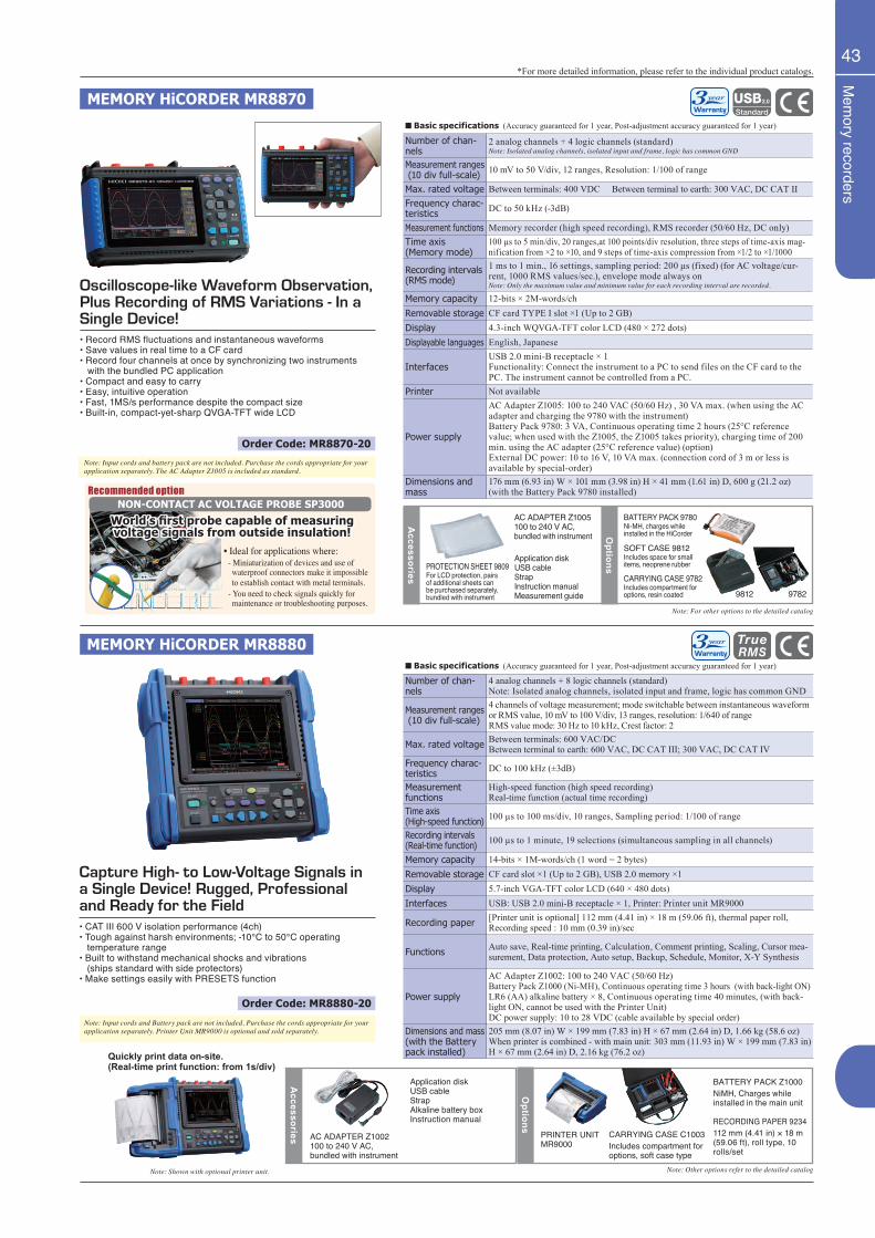
Mem
ory recorders
43
• Record RMS fluctuations and instantaneous waveforms• Save values in real time to a CF card• Record four channels at once by synchronizing two instruments with the bundled PC application• Compact and easy to carry• Easy, intuitive operation• Fast, 1MS/s performance despite the compact size• Built-in, compact-yet-sharp QVGA-TFT wide LCD
Oscilloscope-like Waveform Observation, Plus Recording of RMS Variations - In a Single Device!
MEMORY HiCORDER MR8870
MEMORY HiCORDER MR8880
Capture High- to Low-Voltage Signals in a Single Device! Rugged, Professional and Ready for the Field• CAT III 600 V isolation performance (4ch)• Tough against harsh environments; -10°C to 50°C operating temperature range• Built to withstand mechanical shocks and vibrations (ships standard with side protectors)• Make settings easily with PRESETS function
■ Basic specifications (Accuracy guaranteed for 1 year, Post-adjustment accuracy guaranteed for 1 year)
Number of chan-nels
2 analog channels + 4 logic channels (standard)Note: Isolated analog channels, isolated input and frame, logic has common GND
Measurement ranges (10 div full-scale) 10 mV to 50 V/div, 12 ranges, Resolution: 1/100 of range
Max. rated voltage Between terminals: 400 VDC Between terminal to earth: 300 VAC, DC CAT IIFrequency charac-teristics DC to 50 kHz (-3dB)
Measurement functions Memory recorder (high speed recording), RMS recorder (50/60 Hz, DC only)Time axis(Memory mode)
100 µs to 5 min/div, 20 ranges,at 100 points/div resolution, three steps of time-axis mag-nification from ×2 to ×10, and 9 steps of time-axis compression from ×1/2 to ×1/1000
Recording intervals(RMS mode)
1 ms to 1 min., 16 settings, sampling period: 200 μs (fixed) (for AC voltage/cur-rent, 1000 RMS values/sec.), envelope mode always onNote: Only the maximum value and minimum value for each recording interval are recorded.
Memory capacity 12-bits × 2M-words/chRemovable storage CF card TYPE I slot ×1 (Up to 2 GB)Display 4.3-inch WQVGA-TFT color LCD (480 × 272 dots)Displayable languages English, Japanese
InterfacesUSB 2.0 mini-B receptacle × 1Functionality: Connect the instrument to a PC to send files on the CF card to the PC. The instrument cannot be controlled from a PC.
Printer Not available
Power supply
AC Adapter Z1005: 100 to 240 VAC (50/60 Hz) , 30 VA max. (when using the AC adapter and charging the 9780 with the instrument)Battery Pack 9780: 3 VA, Continuous operating time 2 hours (25°C reference value; when used with the Z1005, the Z1005 takes priority), charging time of 200 min. using the AC adapter (25°C reference value) (option)External DC power: 10 to 16 V, 10 VA max. (connection cord of 3 m or less is available by special-order)
Dimensions and mass
176 mm (6.93 in) W × 101 mm (3.98 in) H × 41 mm (1.61 in) D, 600 g (21.2 oz) (with the Battery Pack 9780 installed)
■ Basic specifications (Accuracy guaranteed for 1 year, Post-adjustment accuracy guaranteed for 1 year)
Number of chan-nels
4 analog channels + 8 logic channels (standard) Note: Isolated analog channels, isolated input and frame, logic has common GND
Measurement ranges (10 div full-scale)
4 channels of voltage measurement; mode switchable between instantaneous waveform or RMS value, 10 mV to 100 V/div, 13 ranges, resolution: 1/640 of rangeRMS value mode: 30 Hz to 10 kHz, Crest factor: 2
Max. rated voltage Between terminals: 600 VAC/DCBetween terminal to earth: 600 VAC, DC CAT III; 300 VAC, DC CAT IV
Frequency charac-teristics DC to 100 kHz (±3dB)
Measurement functions
High-speed function (high speed recording)Real-time function (actual time recording)
Time axis(High-speed function) 100 µs to 100 ms/div, 10 ranges, Sampling period: 1/100 of range
Recording intervals(Real-time function) 100 µs to 1 minute, 19 selections (simultaneous sampling in all channels)
Memory capacity 14-bits × 1M-words/ch (1 word = 2 bytes)Removable storage CF card slot ×1 (Up to 2 GB), USB 2.0 memory ×1Display 5.7-inch VGA-TFT color LCD (640 × 480 dots)Interfaces USB: USB 2.0 mini-B receptacle × 1, Printer: Printer unit MR9000
Recording paper [Printer unit is optional] 112 mm (4.41 in) × 18 m (59.06 ft), thermal paper roll, Recording speed : 10 mm (0.39 in)/sec
Functions Auto save, Real-time printing, Calculation, Comment printing, Scaling, Cursor mea-surement, Data protection, Auto setup, Backup, Schedule, Monitor, X-Y Synthesis
Power supply
AC Adapter Z1002: 100 to 240 VAC (50/60 Hz)Battery Pack Z1000 (Ni-MH), Continuous operating time 3 hours (with back-light ON)LR6 (AA) alkaline battery × 8, Continuous operating time 40 minutes, (with back-light ON, cannot be used with the Printer Unit)DC power supply: 10 to 28 VDC (cable available by special order)
Dimensions and mass(with the Battery pack installed)
205 mm (8.07 in) W × 199 mm (7.83 in) H × 67 mm (2.64 in) D, 1.66 kg (58.6 oz)When printer is combined - with main unit: 303 mm (11.93 in) W × 199 mm (7.83 in) H × 67 mm (2.64 in) D, 2.16 kg (76.2 oz)
Note: Input cords and battery pack are not included. Purchase the cords appropriate for your application separately. The AC Adapter Z1005 is included as standard.
Note: Input cords and Battery pack are not included. Purchase the cords appropriate for your application separately. Printer Unit MR9000 is optional and sold separately.
Accessories
PROTECTION SHEET 9809For LCD protection, pairs of additional sheets can be purchased separately, bundled with instrument
AC ADAPTER Z1005100 to 240 V AC, bundled with instrument
Application disk USB cableStrapInstruction manualMeasurement guide
Options
BATTERY PACK 9780Ni-MH, charges while installed in the HiCorder
SOFT CASE 9812Includes space for small items, neoprene rubber
CARRYING CASE 9782Includes compartment for options, resin coated
Note: For other options to the detailed catalog
Accessories AC ADAPTER Z1002
100 to 240 V AC, bundled with instrument
Application diskUSB cableStrapAlkaline battery boxInstruction manual
Options
PRINTER UNIT MR9000
BATTERY PACK Z1000NiMH, Charges while installed in the main unit
RECORDING PAPER 9234112 mm (4.41 in) × 18 m (59.06 ft), roll type, 10 rolls/set
CARRYING CASE C1003Includes compartment for options, soft case type
Note: Other options refer to the detailed catalog
*For more detailed information, please refer to the individual product catalogs.
Quickly print data on-site. (Real-time print function: from 1s/div)
Note: Shown with optional printer unit.
Order Code: MR8880-20
Order Code: MR8870-20
9812 9782
Recommended option
• Ideal for applications where: - Miniaturization of devices and use of waterproof connectors make it impossible to establish contact with metal terminals. - You need to check signals quickly for maintenance or troubleshooting purposes.
NON-CONTACT AC VOLTAGE PROBE SP3000
World’s first probe capable of measuring voltage signals from outside insulation!
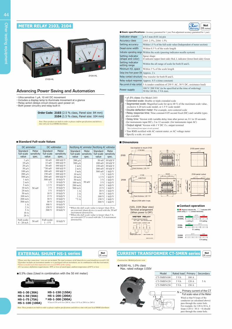
Other testing equipm
ent
44
Note: These products are built-to-order so please confirm specifications and delivery time with your local HIOKI distributor.
2103-HL2104-HL
*1When the full-scale value is larger than 20 A, an external shunt device is used with the 50 mV instrument denoted by.*2When the full-scale value is larger than 5 A, an external CT is used with the 5 A instrument denoted by.
DC ammeter DC voltmeterStandard full-scale
value
Meter sensitivity
spec.
Standard full-scale
value
Meter sensitivity
spec.1 μA
10 μA20 μA50 μA
100 μA200 μA500 μA
1 mA2 mA5 mA
10 mA20 mA50 mA
100 mA200 mA500 mA
1 A2 A5 A
10 A20 A
50 mV
10 mV15 mV30 mV
*150 mV100 mV150 mV300 mV500 mV
1 V1.5 V
3 V5 V
10 V15 V30 V50 V
100 V150 V300 V
100 kΩ/V100 kΩ/V100 kΩ/V100 kΩ/V100 kΩ/V100 kΩ/V100 kΩ/V10 kΩ/V10 kΩ/V10 kΩ/V10 kΩ/V10 kΩ/V10 kΩ/V10 kΩ/V10 kΩ/V10 kΩ/V10 kΩ/V10 kΩ/V10 kΩ/V
Full-scale: 4 - 20 mA 50 mV Full-scale:
1 - 5 V 10 kΩ/V
■ Standard Full-scale Values
Rectifying AC ammeter Rectifying AC voltmeter
Standard full-scale
value
Meter sensitivity
spec.
Standard full-scale
value
Meter sensitivity
spec.200 μA500 μA 1 mA2 mA5 mA
10 mA20 mA50 mA
100 mA200 mA500 mA
1 A2 A3 A
*25 A
50 mV
50 mV100 mV150 mV300 mV500 mV
1 V1.5 V
3 V5 V
10 V15 V30 V50 V
100 V150 V300 V
10 kΩ/V10 kΩ/V10 kΩ/V10 kΩ/V1 kΩ/V1 kΩ/V1 kΩ/V1 kΩ/V1 kΩ/V1 kΩ/V1 kΩ/V1 kΩ/V1 kΩ/V1 kΩ/V1 kΩ/V1 kΩ/V
■ Basic specifications (Accuracy guaranteed for 1 year, Post-adjustment accuracy guaranteed for 1 year)
Indicator shape φ 0.3 mm (0.01 in) pinAccuracy class 2103: 2.5%, 2104: 1.5%Setting accuracy Within 1.5 % of the full scale value (Independent of meter section)Dead-zone width Within 0.5 % of the scale lengthIndicator operating range Within the scale (passing indicator needle system)Setting indicator(shape and color)
Spear shapeH indicator (upper-limit side): Red, L indicator (lower-limit side): Green
Setting indicator setting range Within the all range of scale for both H and L
Minimum H/L space Within 3 % of the scale lengthDelay time from power ON Approx. 2 sRelay contact structure One transfer for both H and LRelay output response Approx. 0.5 s (time constant)Max.current of relay contact 5 A (under condition of 250 V AC, 30 V DC, resistance load)
Power supply 100 V/ 200 VAC (to be specified at the time of ordering)50 Hz/ 60 Hz, 3 VA max.
METER RELAY 2103, 2104
Advancing Power Saving and Automation• Ultra sensitive 1 µA, 10 mV DC movement• Includes a display lamp to illuminate movement at a glance• Relay action delays circuit closure upon power on• Both power circuitry and relay built in
Special specifications
• ±1.5% class: For Model 2103• Extended scale: Double or triple extended scale• Segmented scale: Magnified scale for up to 40 % of the maximum scale value, exclusive 4-20 mA scale model, or 1-5 V scale model• Double deflection meter: For example, zero-centered scale• Relay response time: Time constant 0.05 second fixed (DC) and variable types also available
• Delay time: Version with variable delay time after power on. 0.1 to 10 seconds: (for instruments input DC), 2 to 12 seconds: (for instruments input AC)
• Output signal: Version with 1 V DC /f.s. output terminal *Not isolated from input circuit ground.• True RMS rectified with AC current meter, or AC voltage meter• Specify a scale, or a unit
■ Dimensions
H setting
L setting
L setting H setting
2103HL2104HL
2103L2104L
2103H2104H
Regions indicate ON, indicates OFF.(when using – contact terminals)
■ Contact operation2103, 2104 (Rear view)Terminal arrangement(When power is OFF)
*Please note that connections’ cores are not included. The total resistance of all shunt devices used should not exceed 0.1 Ω. *If product includes an instrument number or is packaged with an instrument, use in combination with that instrument. *Select a model such that input does not exceed 80% of the rating. (0.5 accuracy definition requirements: 80% or less of rated input, ambient temperature of 60°C or less)
■ 0.5% class (Used in combination with the 50 mV meter)
EXTERNAL SHUNT HS-1 series
HS-1-30 (30A)HS-1-50 (50A)HS-1-75 (75A)HS-1-100 (100A) *Class 0.5% at 0 A to 200 A, class 1.0 % at 200 A to 240 A
Construction: Molded polyester resin
■ 50/60 Hz, 1.0% class Max. rated voltage 1150V
CURRENT TRANSFORMER CT-5MRN series
*
HS-1-150 (150A)HS-1-200 (200A)HS-1-300 (300A)
Wind so that N loops of the conductor (as calculated above) pass through the center hole. For example, for 120 A:30 A, 4 loops (120 A / 30 A = 4) should pass through the center hole.
Order Code: 2103 (2.5 % class, Panel size: 84 mm) 2104 (1.5 % class, Panel size: 104 mm)
Model Rated load Primary SecondaryCT-5MRN100 5 VA 100 A
5 ACT-5MRN120 5 VA 120 ACT-5MRN150 5 VA 150 A
Primary current of the CTFull scale value of the Meter
N =
Note: These products are built-to-order so please confirm specifications and delivery time with your local HIOKI distributor.
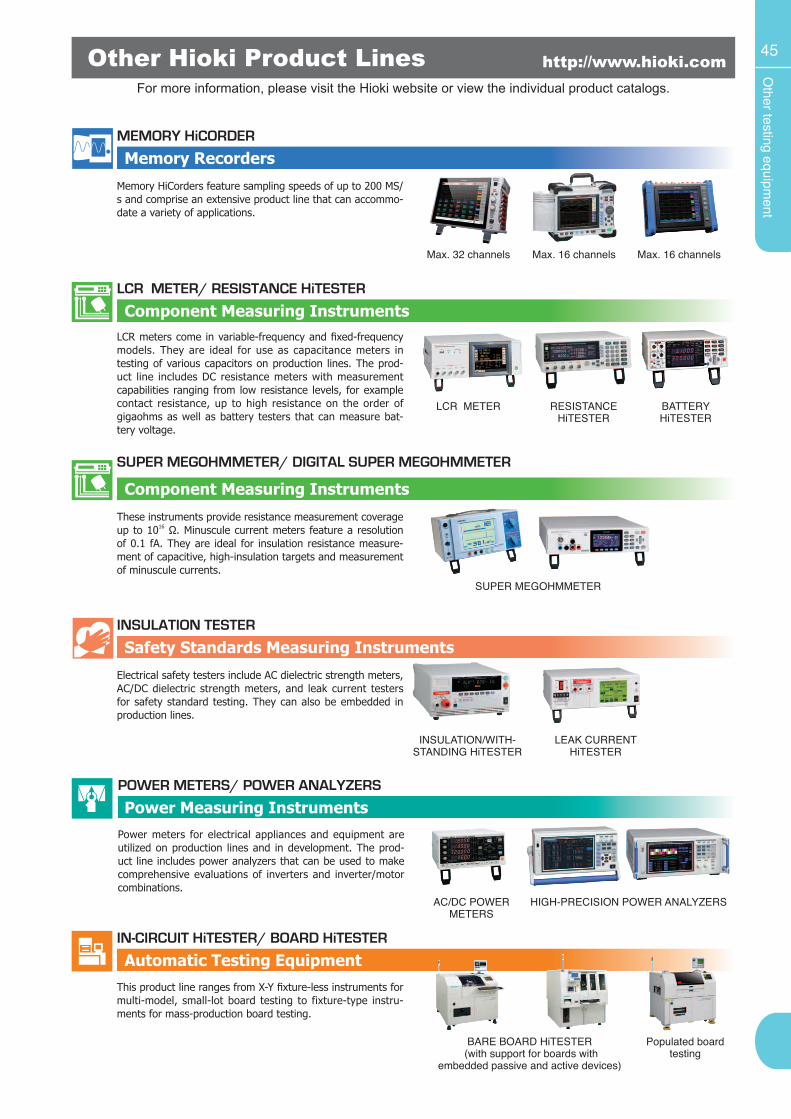
Other testing equipm
ent
45Other Hioki Product Lines http://www.hioki.com
Automatic Testing EquipmentIN-CIRCUIT HiTESTER/ BOARD HiTESTER
BARE BOARD HiTESTER (with support for boards with
embedded passive and active devices)
Populated board testing
This product line ranges from X-Y fixture-less instruments for multi-model, small-lot board testing to fixture-type instru-ments for mass-production board testing.
Power Measuring InstrumentsPOWER METERS/ POWER ANALYZERS
AC/DC POWER METERS
HIGH-PRECISION POWER ANALYZERS
Power meters for electrical appliances and equipment are utilized on production lines and in development. The prod-uct line includes power analyzers that can be used to make comprehensive evaluations of inverters and inverter/motor combinations.
For more information, please visit the Hioki website or view the individual product catalogs.
Safety Standards Measuring InstrumentsINSULATION TESTER
INSULATION/WITH-STANDING HiTESTER
LEAK CURRENT HiTESTER
Electrical safety testers include AC dielectric strength meters, AC/DC dielectric strength meters, and leak current testers for safety standard testing. They can also be embedded in production lines.
Component Measuring Instruments
SUPER MEGOHMMETER/ DIGITAL SUPER MEGOHMMETER
SUPER MEGOHMMETER
These instruments provide resistance measurement coverage up to 1016 Ω. Minuscule current meters feature a resolution of 0.1 fA. They are ideal for insulation resistance measure-ment of capacitive, high-insulation targets and measurement of minuscule currents.
Component Measuring InstrumentsLCR METER/ RESISTANCE HiTESTER
LCR METER RESISTANCE HiTESTER
BATTERY HiTESTER
LCR meters come in variable-frequency and fixed-frequency models. They are ideal for use as capacitance meters in testing of various capacitors on production lines. The prod-uct line includes DC resistance meters with measurement capabilities ranging from low resistance levels, for example contact resistance, up to high resistance on the order of gigaohms as well as battery testers that can measure bat-tery voltage.
Memory RecordersMEMORY HiCORDER
Max. 32 channels Max. 16 channels
Memory HiCorders feature sampling speeds of up to 200 MS/s and comprise an extensive product line that can accommo-date a variety of applications.
Max. 16 channels
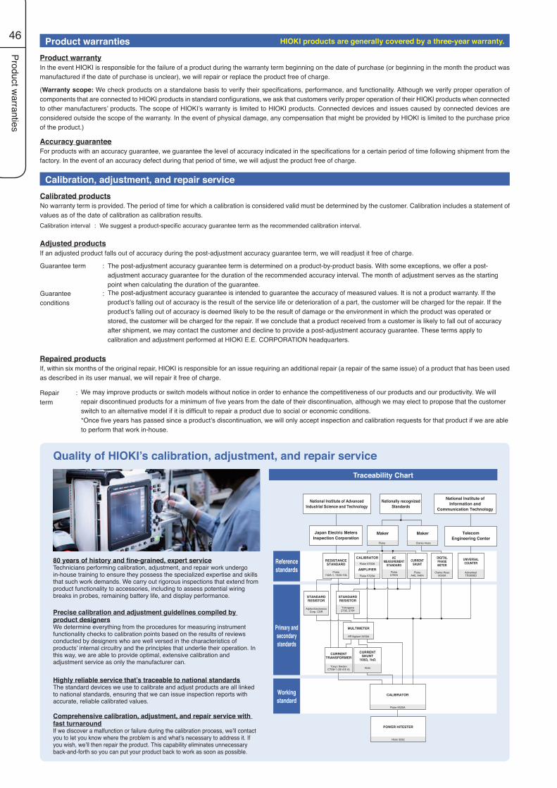
Product warranties
46 Product warrantiesProduct warrantyIn the event HIOKI is responsible for the failure of a product during the warranty term beginning on the date of purchase (or beginning in the month the product was manufactured if the date of purchase is unclear), we will repair or replace the product free of charge.
(Warranty scope: We check products on a standalone basis to verify their specifications, performance, and functionality. Although we verify proper operation of components that are connected to HIOKI products in standard configurations, we ask that customers verify proper operation of their HIOKI products when connected to other manufacturers’ products. The scope of HIOKI’s warranty is limited to HIOKI products. Connected devices and issues caused by connected devices are considered outside the scope of the warranty. In the event of physical damage, any compensation that might be provided by HIOKI is limited to the purchase price of the product.)
Accuracy guaranteeFor products with an accuracy guarantee, we guarantee the level of accuracy indicated in the specifications for a certain period of time following shipment from the factory. In the event of an accuracy defect during that period of time, we will adjust the product free of charge.
Calibration, adjustment, and repair service
Quality of HIOKI’s calibration, adjustment, and repair serviceTraceability Chart
80 years of history and fine-grained, expert serviceTechnicians performing calibration, adjustment, and repair work undergo in-house training to ensure they possess the specialized expertise and skills that such work demands. We carry out rigorous inspections that extend from product functionality to accessories, including to assess potential wiring breaks in probes, remaining battery life, and display performance.
Precise calibration and adjustment guidelines compiled by product designersWe determine everything from the procedures for measuring instrument functionality checks to calibration points based on the results of reviews conducted by designers who are well versed in the characteristics of products’ internal circuitry and the principles that underlie their operation. In this way, we are able to provide optimal, extensive calibration and adjustment service as only the manufacturer can.
Highly reliable service that’s traceable to national standardsThe standard devices we use to calibrate and adjust products are all linked to national standards, ensuring that we can issue inspection reports with accurate, reliable calibrated values.
Comprehensive calibration, adjustment, and repair service with fast turnaroundIf we discover a malfunction or failure during the calibration process, we’ll contact you to let you know where the problem is and what’s necessary to address it. If you wish, we’ll then repair the product. This capability eliminates unnecessary back-and-forth so you can put your product back to work as soon as possible.
Adjusted productsIf an adjusted product falls out of accuracy during the post-adjustment accuracy guarantee term, we will readjust it free of charge.
Guarantee term : The post-adjustment accuracy guarantee term is determined on a product-by-product basis. With some exceptions, we offer a post-adjustment accuracy guarantee for the duration of the recommended accuracy interval. The month of adjustment serves as the starting point when calculating the duration of the guarantee.
Guarantee conditions
: The post-adjustment accuracy guarantee is intended to guarantee the accuracy of measured values. It is not a product warranty. If the product’s falling out of accuracy is the result of the service life or deterioration of a part, the customer will be charged for the repair. If the product’s falling out of accuracy is deemed likely to be the result of damage or the environment in which the product was operated or stored, the customer will be charged for the repair. If we conclude that a product received from a customer is likely to fall out of accuracy after shipment, we may contact the customer and decline to provide a post-adjustment accuracy guarantee. These terms apply to calibration and adjustment performed at HIOKI E.E. CORPORATION headquarters.
Repaired productsIf, within six months of the original repair, HIOKI is responsible for an issue requiring an additional repair (a repair of the same issue) of a product that has been used as described in its user manual, we will repair it free of charge.
Repair term
: We may improve products or switch models without notice in order to enhance the competitiveness of our products and our productivity. We will repair discontinued products for a minimum of five years from the date of their discontinuation, although we may elect to propose that the customer switch to an alternative model if it is difficult to repair a product due to social or economic conditions.*Once five years has passed since a product’s discontinuation, we will only accept inspection and calibration requests for that product if we are able to perform that work in-house.
Calibrated productsNo warranty term is provided. The period of time for which a calibration is considered valid must be determined by the customer. Calibration includes a statement of values as of the date of calibration as calibration results. Calibration interval : We suggest a product-specific accuracy guarantee term as the recommended calibration interval.
Primary andsecondarystandards
Referencestandards
Workingstandard
National Institute of AdvancedIndustrial Science and Technology
Nationally recognizedStandards
CALIBRATOR
Fluke 5520A
POWER HiTESTER
Hioki 3332
National Institute ofInformation and
Communication Technology
Japan Electric MetersInspection Corporation
Maker
Fluke
Maker
Clarke Hess
TelecomEngineering Center
RESISTANCESTANDARD
Fluke742A-1, 742A-10k
CALIBRATORFluke 5700A
AMPLIFIER
Fluke 5725A
STANDARDRESISTOR
Alpha ElectronicsCorp. CSR
STANDARDRESISTOR
Yokogawa2792, 2794
CURRENTTRANSFORMER
Tokyo SeidenCTS8-1 (50 A/5 A)
CURRENTSHUNT
100Ω, 1kΩ
Hioki
ACMEASUREMENT
STANDARD
Fluke5790A
FlukeA40, A40A
CURRENTSHUNT
Clarke Hess6000A
DIGITALPHASEMETER
AdvantestTR5830D
UNIVERSALCOUNTER
MULTIMETER
HP/Agilent 3458A
HIOKI products are generally covered by a three-year warranty.
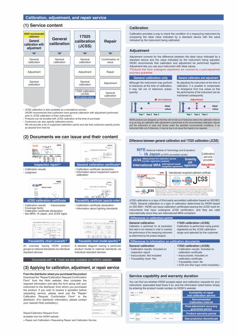
Calibration, adjustment, and repair service
(1) Service content
(2) Documents we can issue and their content
(3) Applying for calibration, adjustment, or repair service
•JCSScalibrationisalsoavailableasastandaloneservice.(HIOKIrecommendsthatcustomershavegeneralcalibrationwithadjustmentperformedpriortoJCSScalibrationoftheirinstrument.)
•ProductscanbebundledwithJCSScalibrationatthetimeofpurchase.•Customerscanalsospecifycalibrationpoints.Wewillprovidealistofsupportedcalibrationpointsandaskthatcustomersspecifypointsasdesiredfromthatlist.
Traceability chart (overall)An overview tracing HIOKI productgroupstonationalstandardsviaindividualstandarddevices
Documentswith""markarealsoavailableonHIOKI'swebsite.
Traceability chart (model-specific)A detailed diagram tracing a particularproductmodeltonationalstandardsviaindividualstandarddevices
General calibration with
adjustment
HIOKI recommended calibration
Adjustment
Generalcalibration
Generalcalibration
General calibration
Generalcalibration
Adjustment
17025 calibration
(JCSS)
Generalcalibration
Generalcalibration
17025calibration(JCSS)
JCSScalibrationcertificate
Confirmationofissue
Repair
Adjustment
Repair
Generalcalibration
•Calibrationresults•Judgment
Inspection report •Calibrationcertificatedeclaration•Informationaboutequipmentusedincalibration
General calibration certificate
•Calibrationresults•Inaccuracies•Coveragefactor•Calibrationcertificatedeclaration•ilac-MRA,IAJapan,andJCSSlogos
JCSS calibration certificate•Calibrationcertificatedeclaration•Informationaboutlightingstandards
Traceability certificate (special-order)
Differences in calibration points17025 calibration (JCSS)CalibrationisperformedusingpointsregisteredastheJCSScalibrationrangeandselectedbythecustomer.
General calibrationCalibration is performed for all parametersthatneedtobecheckedinordertomaintaintheperformanceofthemeasuringinstrumentasdeterminedbytheproductdesigner.
Differences in information on calibration documentsGeneral calibration•Calibrationresults:Includedoninspectionreport
•Inaccuracies:Notincluded•Traceabilitychart:Yes
17025 calibration (JCSS)•Calibrationresults:Includedoncalibrationcertificate
•Inaccuracies:Includedoncalibrationcertificate
•Traceabilitychart:No(*JCSSandotherlogoscertifytraceability.)
Calibration
Service capability and warranty duration
Adjustment
Difference between general calibration and 17025 calibration (JCSS)
Calibrationprovidesawaytochecktheconditionofameasuringinstrumentbycomparing the ideal value indicated by a standard device with the valueindicatedbytheinstrumentbeingcalibrated.
YoucanfindoutwhetherHIOKIacceptsrepairandcalibrationrequestsforyourinstrument,associatedleadtimesifso,andtheinformationlistedbelowsimplybyenteringtheproductmodelnumberonHIOKI’swebsite.
Availability of repair and calibration service
RecommendedCalibration Interval
Post-adjustment accuracyguarantee period
Product warranty period
Date production discontinued
Adjustmentcorrects for thedifferencebetweenthe idealvalue indicatedbyastandard device and the value indicated by the instrument being adjusted.HIOKI recommends that calibration and adjustment be performed together.Adjustmentletsyouuseyourinstrumentwithidealvalues.*Products thathaveundergoneadjustmentarecoveredbyapost-adjustmentaccuracyguarantee.
JCSScalibrationisatypeofthird-party-accreditedcalibrationbasedonISO/IEC17025.GeneralcalibrationisatypeofcalibrationdeterminedbyHIOKIbasedonISO9001.HIOKIcanissuecalibrationcertificatesbearingtheJCSSmarkforinstruments that have undergone JCSS certification, and they are validinternationallysincetheyareinternationalMRA-compliant.
Althoughtheinstrumentmayperformtotoleranceatthetimeofcalibration,it may fall out of tolerance subse-quently.
Byadjustingtheinstrumentatthetimeofcalibration, it is possible to compensatefor divergence from true values so thattheperformanceoftheinstrumentcanbemaintainedsubsequently.
HIOKIproductsaredesignedsothattheywillnotfalloutoftolerancebeforethecalibrationintervalisupaslongascalibrationwithadjustmentisperformedattherecommendedcalibrationintervaland the instrument is used and stored under the specified environmental conditions. If aninstrumentfallsoutoftolerance,itmaybeduetoanissuethatneedstoberepaired.
General calibration only General calibration and adjustment
Tole
ranc
e
Year 1 Year 2 Year 3
Out of tolerance
Ideal value
Adjustment
Ideal value
Tole
ranc
e
Year 1 Year 2 Year 3
Internationally recognized calibration certificate
NITE (National Institute of Technology and Evaluation)
IA Japan (a NITE-accredited center)
JCSSInternational MRA
Screeningand
registration
Calibrationserviceprovider
Issuance
This is the mark of the calibration service provider registration program based on the Measurement Act. JCSS-registered service providers are registered under the ISO/IEC 17025 standard. HIOKI E.E. CORPORATION is an international MRA-capable JCSS-accredited service provider. HIOKI’s accreditation number is JCSS 0156.
(Measurement Act calibration service provider registration program)
(international mutual recognition agreement)
From the distributor where you purchased the productDownloadthe“Repair/CalibrationRequestConfirmationForm” from the Hioki website, then complete therequiredinformationandtaketheformalongwithyourinstrumenttothedistributorfromwhomyoupurchasedtheproduct. If youwish to receiveaquotationbeforerequesting service, please send just the “Repair/Calibration Request Confirmation Form” to thedistributor. (For distributor information, please contactyournearestHiokisubsidiary.)
Repair/CalibrationRequestFormAvailablefromtheHIOKIwebsite:>RepairandCalibration>RequestingRepairandCalibrationService
*
*
*
*
*
■ All information correct as of December 1, 2018.■ Company names and Product names appearing in this catalog are trademarks or registered trademarks of
various companies.■ All specifications are subject to change without notice.
0002E11-8ZB-11KPrinted in Japan
DISTRIBUTED BY
This brochure has been printed with vegetable oil ink.
HEADQUARTERS 81 Koizumi Ueda, Nagano 386-1192 JAPAN www.hioki.com
H HIOKI USA CORPORATION6 Corporate Drive, Cranbury, NJ 08512, U.S.A.TEL +1-609-409-9109FAX [email protected]
Western Regional Office21250 Hawthorne Boulevard, Suite 500Torrance, CA 90503U.S.A.TEL +1-310-792-7041
H HIOKI (Shanghai) SALES & TRADING CO., LTD.Room 4705 Raffles City Office TowerNo.268 Xizang Road (M)Shanghai, 200001, P.R.ChinaTEL +86-21-6391-0090/0092FAX [email protected]
Beijing Representative OfficeUnit 808 Taikang Financial TowerNo.38 Dong San Huan Bei RoadChaoyang DistrictBeijing 100026, P.R.ChinaTEL +86-10-8587-9168FAX [email protected]
Guangzhou Representative OfficeRoom A-3206 Victory Plaza Services Center103 Tiyuxi Road, Tianhe DistrictGuangzhou, 510620, P.R.ChinaTEL +86-20-3839-2673/2676FAX +86-20-3839-2679 [email protected]
Shenzhen Representative OfficeRoom 1308 International Chamber of Commerce TowerNo.168 Fuhua Rd.3CBD Futian DistrictShenzhen, 518048, P.R.ChinaTEL +86-755-8303-8357/9243FAX +86-755-8303-9160 [email protected]
H HIOKI SINGAPORE PTE. LTD.33 Ubi Avenue 3, #03-02 Vertex, Singapore 408868TEL +65-6634-7677FAX [email protected]
Thailand Representative Office202 9th Floor, Room 906, Le Concorde TowerRatchadapisek Road, Huay kwangBangkok 10310, ThailandTEL +66-2-051-5323FAX [email protected]
Indonesia Representative OfficeGedung Graha MIR, 1st Floor, Zone CJl. Pemuda No. 9, Rawamangun, PulogadungJakarta Timur 13220, IndonesiaTEL +62-21-2956-9853FAX [email protected]
H HIOKI KOREA CO., LTD.Rm# 1705, East Tower, Hanshin Intervalley 24322 Teheran-ro, Gangnam-guSeoul, 06211, Rep. of KoreaTEL +82-2-2183-8847FAX [email protected]
H HIOKI EUROPE GmbHRudolf-Diesel-Strasse 565760 Eschborn, GermanyTEL +49-6173-31856-0FAX [email protected]
H HIOKI TAIWAN CO., LTD.4F., No.900, Jingguo RdLuzhu DistrictTaoyuan City 33858, Taiwan, R.O.C.TEL +886-3-3467160FAX [email protected]
HIOKI E.E. CORPORATION earned ISO 9001 certification in 1993 and ISO 14001 certification in 1997. For more information, please see “About the Catalog.”
Related Documents


