ORIGINAL ARTICLE Transverse changes determined by rapid and slow maxillary expansion – a low-dose CT-based randomized controlled trial R. Martina I. Cioffi M. Farella P. Leone P. Manzo G. Matarese M. Portelli R. Nucera G. Cordasco Authors' affiliations: R. Martina, I. Cioffi, M. Farella, P. Leone, P. Manzo, Department of Oral Sciences, Section of Orthodontics and Temporomandibular Disorders, University of Naples Federico II, Naples, Italy M. Farella, Department of Oral Sciences, Discipline of Orthodontics, University of Otago, Dunedin, New Zealand G. Matarese, M. Portelli, R. Nucera, G. Cordasco, University of Messina, School of Dentistry, Messina, Italy Correspondence to: Iacopo Cioffi Department of Oral Sciences, Section of Orthodontics and Temporomandibular disorders University of Naples Federico II Via Pansini 5 80131 Napoli Italy E-mails: iacopo.cioffi@gmail.com; iacopo.cioffi@unina.it Martina R., Cioffi I., Farella M., Leone P., Manzo P., Matarese G., Portelli M., Nucera R., Cordasco G. Transverse changes determined by rapid and slow maxillary expansion – a low-dose CT-based randomized controlled trial Orthod Craniofac Res 2012. Ó 2012 John Wiley & Sons A / S Structured Abstract Objectives – To compare transverse skeletal changes produced by rapid (RME) and slow (SME) maxillary expansion using low-dose computed tomography. The null hypothesis was that SME and RME are equally effective in producing skeletal maxillary expansion in patients with posterior crossbite. Setting and Sample Population – This study was carried out at the Department of Oral Sciences, University of Naples Federico II, Italy. Twelve patients (seven males, five females, mean age ± SD: 10.3 ± 2.5 years) were allocated to the SME group and 14 patients (six males, eight females, mean age ± SD: 9.7 ± 1.5 years) to the RME group. Materials and Methods – All patients received a two-band palatal expander and were randomly allocated to either RME or SME. Low-dose computed tomography was used to identify skeletal and dental landmarks and to measure transverse maxillary changes with treatment. Results – A significant increase in skeletal transverse diameters was found in both SME and RME groups (anterior expansion = 2.2 ± 1.4 mm, posterior expansion = 2.2 ± 0.9 mm, pterygoid expansion = 0.9 ±0.8 mm). No significant differences were found between groups at anterior (SME = 1.9 ± 1.3 mm; RME = 2.5 ± 1.5 mm) or posterior (SME = 1.9 ± 1.0 mm; RME = 2.4 ± 0.9 mm) locations, while a statistically significant difference was measured at the pterygoid processes (SME = 0.6 ± 0.6 mm; RME = 1.2 ± 0.9 mm, p = 0.04), which was not clinically relevant. Conclusion – Rapid maxillary expansion is not more effective than SME in expanding the maxilla in patients with posterior crossbite. Key words: low-dose computed tomography; palatal expansion; randomized controlled trial Date: Accepted 13 February 2012 DOI: 10.1111/j.1601-6343.2012.01543.x Ó 2012 John Wiley & Sons A / S

Welcome message from author
This document is posted to help you gain knowledge. Please leave a comment to let me know what you think about it! Share it to your friends and learn new things together.
Transcript
ORIGINAL ARTICLE
Transverse changes determined byrapid and slow maxillary expansion –a low-dose CT-based randomizedcontrolled trial
R. Martina
I. Cioffi
M. Farella
P. Leone
P. Manzo
G. Matarese
M. Portelli
R. Nucera
G. Cordasco
Authors' affiliations:R. Martina, I. Cioffi, M. Farella, P. Leone,
P. Manzo, Department of Oral Sciences,
Section of Orthodontics and
Temporomandibular Disorders, University
of Naples Federico II, Naples, Italy
M. Farella, Department of Oral Sciences,
Discipline of Orthodontics, University of
Otago, Dunedin, New Zealand
G. Matarese, M. Portelli, R. Nucera,
G. Cordasco, University of Messina, School
of Dentistry, Messina, Italy
Correspondence to:
Iacopo Cioffi
Department of Oral Sciences, Section of
Orthodontics and Temporomandibular
disorders
University of Naples Federico II
Via Pansini 5
80131 Napoli
Italy
E-mails: [email protected];
Martina R., Cioffi I., Farella M., Leone P., Manzo P., Matarese G., Portelli M.,
Nucera R., Cordasco G. Transverse changes determined by rapid and slow
maxillary expansion – a low-dose CT-based randomized controlled trial
Orthod Craniofac Res 2012. ! 2012 John Wiley & Sons A ⁄S
Structured Abstract
Objectives – To compare transverse skeletal changes produced by rapid
(RME) and slow (SME) maxillary expansion using low-dose computed
tomography. The null hypothesis was that SME and RME are equally
effective in producing skeletal maxillary expansion in patients with posterior
crossbite.
Setting and Sample Population – This study was carried out at the
Department of Oral Sciences, University of Naples Federico II, Italy. Twelve
patients (seven males, five females, mean age ± SD: 10.3 ± 2.5 years)
were allocated to the SME group and 14 patients (six males, eight females,
mean age ± SD: 9.7 ± 1.5 years) to the RME group.
Materials and Methods – All patients received a two-band palatal
expander and were randomly allocated to either RME or SME. Low-dose
computed tomography was used to identify skeletal and dental landmarks
and to measure transverse maxillary changes with treatment.
Results – A significant increase in skeletal transverse diameters was found
in both SME and RME groups (anterior expansion = 2.2 ± 1.4 mm,
posterior expansion = 2.2 ± 0.9 mm, pterygoid expansion = 0.9 ±0.8 mm).
No significant differences were found between groups at anterior (SME =
1.9 ± 1.3 mm; RME = 2.5 ± 1.5 mm) or posterior (SME = 1.9 ± 1.0 mm;
RME = 2.4 ± 0.9 mm) locations, while a statistically significant difference
was measured at the pterygoid processes (SME = 0.6 ± 0.6 mm;
RME = 1.2 ± 0.9 mm, p = 0.04), which was not clinically relevant.
Conclusion – Rapid maxillary expansion is not more effective than SME in
expanding the maxilla in patients with posterior crossbite.
Key words: low-dose computed tomography; palatal expansion;
randomized controlled trial
Date:
Accepted 13 February 2012
DOI: 10.1111/j.1601-6343.2012.01543.x
! 2012 John Wiley & Sons A ⁄ S
Introduction
Unilateral or bilateral posterior crossbite (PXB) is
a common malocclusion in primary and early
mixed dentition. Previous reports suggest that it
occurs in 8–20% of children (1, 2). Treatment is
recommended in growing patients to improve
occlusal relationships (3, 4), to prevent the
development of mandibular skeletal asymmetries
(5), and to improve jaw function (6). PXB is fre-
quently associated with a maxillary transverse
deficiency (3). Thus, maxillary expansion is often
advocated, which can be achieved using several
therapeutic approaches (7–9).
In growing patients, rapid maxillary expansion
(RME) and slow maxillary expansion (SME) are
routinely used, whereas in adults, surgically
assisted RME is the treatment of choice.
The biological and clinical effects of RME and
SME have been investigated in several studies (9–
13). RME occurs by heavy and continuous forces,
applied in short lapses of time, known to produce
immediate significant effects on maxillary trans-
verse widths. In contrast, SME occurs by more
intermittent and lower forces that are applied over
longer periods. According to the literature, both
expansion modalities appear to produce trans-
verse changes of the maxilla (3, 14–16).
In recent decades, RME has gained preference as
the treatment of choice for PXB. However, the side
effects, such as reported pain, relapse of the
expansion, tipping of the molars, bone loss, gingi-
val recession, and root resorption, have lead some
clinicians toprefer SME. SME is commonly thought
to produce less tissue resistance around the cir-
cum-maxillary structures and, therefore, improve
bone formation in the inter-maxillary suture,
reducing the force-related side effects of RME (15).
Currently, the choice among the two expansion
modalities relies on clinical experience and atti-
tude of the practitioner because of the lack of good
scientific evidence (i.e., randomized controlled
trials comparing the two treatment modalities).
The use of novel imaging techniques in the
craniofacial region as well as the availability of
new software for three-dimensional rendering
allows for high precision and accuracy when
measuring the distances between skeletal land-
marks and low radiation exposure for the patient
(17–19). The purpose of this study was to compare
the transverse skeletal changes determined by
RME and SME by means of low-dose computed
tomography (CT). The null hypothesis was that
SME and RME were equally effective in increasing
skeletal maxillary transverse widths in growing
patients affected with posterior crossbite.
Material and methods
The study was a randomized controlled trial. The
power analysis was based upon previous esti-
mates of RME transverse skeletal effects (20) and
indicated that 12 patients were needed for each
treatment group (difference to detect ‡2.5 mm,
SD = 2.0 mm, a = 0.05, power 80%).
Patients up to 13 years old (males) and 12 years
old (females) who were seeking orthodontic
treatment were screened by a clinical instructor
(PM) of the Postgraduate Programme in Ortho-
dontics at the Department of Orthodontics, Uni-
versity of Naples Federico II, Italy, between May
2006 and October 2007. Subjects with erupted
upper permanent first molars and unilateral or
bilateral molar full cusp PXB whose parents were
willing to participate in the study were included.
Patients with severe periodontal disease (peri-
odontal probing >4 mm) measured at permanent
first upper molars, congenital syndromes, defects,
or previous orthodontic treatment were excluded.
Enrolled subjects were allocated to the two
treatment groups, that is, RME or SME, by a bal-
anced block randomization using gender as
stratifying factor. A single operator (PL) allocated
the patients by means of a custom-made Java
script and was responsible for the allocation
concealment, that is, the allocation was disclosed
only when a new patient was enrolled in the trial.
The Institutional Review Board and the local
Ethics Committee approved this study. Informed
consent was provided by the patient!s parents.
Clinical protocol
For each patient, the medical and orthodontic
histories, intraoral and extraoral photographs, CT
2 Orthod Craniofac Res 2012
Martina et al. Rapid vs. slow maxillary expansion
data, and dental casts were collected prior to
placement of the appliance (T0 time).
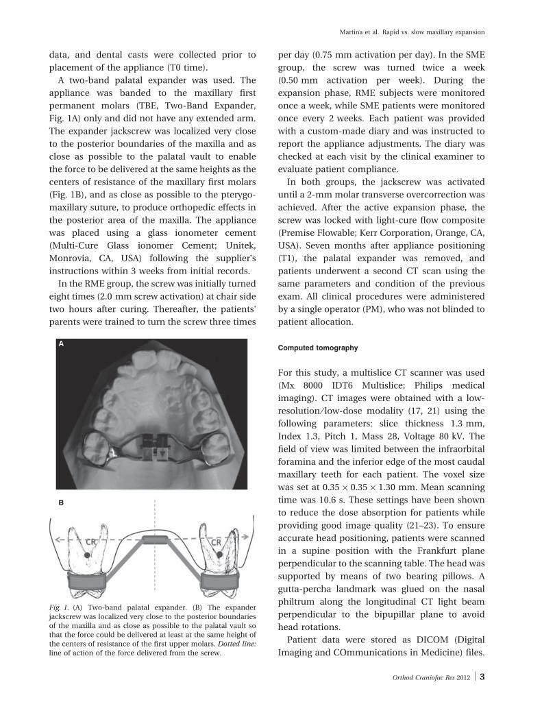
A two-band palatal expander was used. The
appliance was banded to the maxillary first
permanent molars (TBE, Two-Band Expander,
Fig. 1A) only and did not have any extended arm.
The expander jackscrew was localized very close
to the posterior boundaries of the maxilla and as
close as possible to the palatal vault to enable
the force to be delivered at the same heights as the
centers of resistance of the maxillary first molars
(Fig. 1B), and as close as possible to the pterygo-
maxillary suture, to produce orthopedic effects in
the posterior area of the maxilla. The appliance
was placed using a glass ionometer cement
(Multi-Cure Glass ionomer Cement; Unitek,
Monrovia, CA, USA) following the supplier!sinstructions within 3 weeks from initial records.
In the RME group, the screw was initially turned
eight times (2.0 mm screw activation) at chair side
two hours after curing. Thereafter, the patients!parents were trained to turn the screw three times
per day (0.75 mm activation per day). In the SME
group, the screw was turned twice a week
(0.50 mm activation per week). During the
expansion phase, RME subjects were monitored
once a week, while SME patients were monitored
once every 2 weeks. Each patient was provided
with a custom-made diary and was instructed to
report the appliance adjustments. The diary was
checked at each visit by the clinical examiner to
evaluate patient compliance.
In both groups, the jackscrew was activated
until a 2-mm molar transverse overcorrection was
achieved. After the active expansion phase, the
screw was locked with light-cure flow composite
(Premise Flowable; Kerr Corporation, Orange, CA,
USA). Seven months after appliance positioning
(T1), the palatal expander was removed, and
patients underwent a second CT scan using the
same parameters and condition of the previous
exam. All clinical procedures were administered
by a single operator (PM), who was not blinded to
patient allocation.
Computed tomography
For this study, a multislice CT scanner was used
(Mx 8000 IDT6 Multislice; Philips medical
imaging). CT images were obtained with a low-
resolution ⁄ low-dose modality (17, 21) using the
following parameters: slice thickness 1.3 mm,
Index 1.3, Pitch 1, Mass 28, Voltage 80 kV. The
field of view was limited between the infraorbital
foramina and the inferior edge of the most caudal
maxillary teeth for each patient. The voxel size
was set at 0.35 · 0.35 · 1.30 mm. Mean scanning
time was 10.6 s. These settings have been shown
to reduce the dose absorption for patients while
providing good image quality (21–23). To ensure
accurate head positioning, patients were scanned
in a supine position with the Frankfurt plane
perpendicular to the scanning table. The head was
supported by means of two bearing pillows. A
gutta-percha landmark was glued on the nasal
philtrum along the longitudinal CT light beam
perpendicular to the bipupillar plane to avoid
head rotations.
Patient data were stored as DICOM (Digital
Imaging and COmmunications in Medicine) files.
A
B
Fig. 1. (A) Two-band palatal expander. (B) The expanderjackscrew was localized very close to the posterior boundariesof the maxilla and as close as possible to the palatal vault sothat the force could be delivered at least at the same height ofthe centers of resistance of the first upper molars. Dotted line:line of action of the force delivered from the screw.
Orthod Craniofac Res 2012 3
Martina et al. Rapid vs. slow maxillary expansion
Thereafter, they were imported to software
(Materialise Mimics 8.1, Leuven, Belgium) for
post-processing.
Measurements
To construct a set of reference planes, two skeletal
landmarks were primarily identified in the CT
scans: the oval point right and left (OVPr ⁄OVPl),
which were defined as the most posterior points
of the right and left oval foramina in the cortex of
the sphenoid, at its middle cranio-caudal height.
These points were primarily localized in the ori-
ginal coronal CT slices. A segment connecting
OVPr and OVPl was then constructed. The original
axial CT slices were oriented according to the
segment OVpR – OVpL using the software.
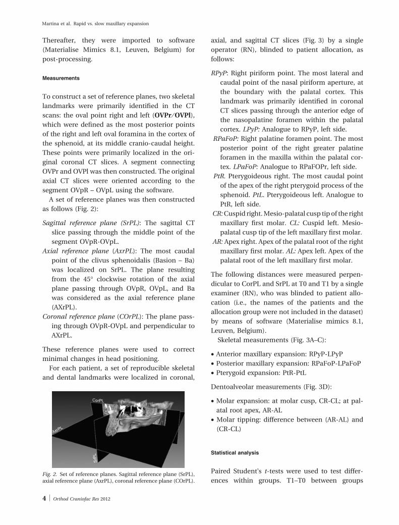
A set of reference planes was then constructed
as follows (Fig. 2):
Sagittal reference plane (SrPL): The sagittal CT
slice passing through the middle point of the
segment OVpR-OVpL.
Axial reference plane (AxrPL): The most caudal
point of the clivus sphenoidalis (Basion – Ba)
was localized on SrPL. The plane resulting
from the 45" clockwise rotation of the axial
plane passing through OVpR, OVpL, and Ba
was considered as the axial reference plane
(AXrPL).
Coronal reference plane (COrPL): The plane pass-
ing through OVpR-OVpL and perpendicular to
AXrPL.
These reference planes were used to correct
minimal changes in head positioning.
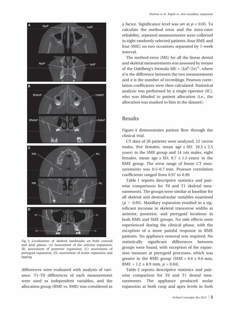
For each patient, a set of reproducible skeletal
and dental landmarks were localized in coronal,
axial, and sagittal CT slices (Fig. 3) by a single
operator (RN), blinded to patient allocation, as
follows:
RPyP: Right piriform point. The most lateral and
caudal point of the nasal piriform aperture, at
the boundary with the palatal cortex. This
landmark was primarily identified in coronal
CT slices passing through the anterior edge of
the nasopalatine foramen within the palatal
cortex. LPyP: Analogue to RPyP, left side.
RPaFoP: Right palatine foramen point. The most
posterior point of the right greater palatine
foramen in the maxilla within the palatal cor-
tex. LPaFoP: Analogue to RPaFOPr, left side.
PtR. Pterygoideous right. The most caudal point
of the apex of the right pterygoid process of the
sphenoid. PtL. Pterygoideous left. Analogue to
PtR, left side.
CR:Cuspid right.Mesio-palatal cusp tipof the right
maxillary first molar. CL: Cuspid left. Mesio-
palatal cusp tip of the left maxillary first molar.
AR: Apex right. Apex of the palatal root of the right
maxillary first molar. AL: Apex left. Apex of the
palatal root of the left maxillary first molar.
The following distances were measured perpen-
dicular to CorPL and SrPL at T0 and T1 by a single
examiner (RN), who was blinded to patient allo-
cation (i.e., the names of the patients and the
allocation group were not included in the dataset)
by means of software (Materialise mimics 8.1,
Leuven, Belgium).
Skeletal measurements (Fig. 3A–C):
• Anterior maxillary expansion: RPyP-LPyP
• Posterior maxillary expansion: RPaFoP-LPaFoP
• Pterygoid expansion: PtR-PtL
Dentoalveolar measurements (Fig. 3D):
• Molar expansion: at molar cusp, CR-CL; at pal-
atal root apex, AR-AL
• Molar tipping: difference between (AR-AL) and
(CR-CL)
Statistical analysis
Paired Student!s t-tests were used to test differ-
ences within groups. T1–T0 between groupsFig. 2. Set of reference planes. Sagittal reference plane (SrPL),axial reference plane (AxrPL), coronal reference plane (COrPL).
4 Orthod Craniofac Res 2012
Martina et al. Rapid vs. slow maxillary expansion
differences were evaluated with analysis of vari-
ance. T1–T0 differences of each measurement
were used as independent variables, and the
allocation group (RME vs. SME) was considered as
a factor. Significance level was set at p < 0.05. To
calculate the method error and the intra-rater
reliability, repeated measurements were collected
in eight randomly selected patients (four RME and
four SME) on two occasions separated by 1-week
interval.
The method error (ME) for all the linear dental
and skeletal measurements was assessed bymeans
of the Dahlberg!s formula ME = (Sd2 ⁄ 2n)!, where
d is the difference between the two measurements
and n is the number of recordings. Pearson corre-
lation coefficients were then calculated. Statistical
analysis was performed by a single operator (IC),
who was blinded to patient allocation (i.e., the
allocation was masked to him in the dataset).
Results
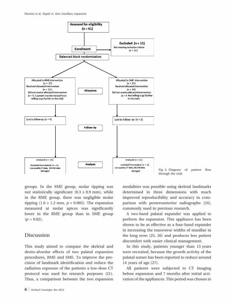
Figure 4 demonstrates patient flow through the
clinical trial.
CT data of 26 patients were analyzed, 12 (seven
males, five females, mean age ± SD: 10.3 ± 2.5
years) in the SME group and 14 (six males, eight
females, mean age ± SD; 9.7 ± 1.5 years) in the
RME group. The error range of linear CT mea-
surements was 0.5–0.7 mm. Pearson correlation
coefficients ranged from 0.97 to 0.99.
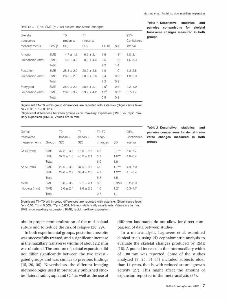
Table 1 reports descriptive statistics and pair-
wise comparisons for T0 and T1 skeletal mea-
surements. The groups were similar at baseline for
all skeletal and dentoalveolar variables examined
(p > 0.05). Maxillary expansion resulted in a sig-
nificant increase in skeletal transverse widths at
anterior, posterior, and pterygoid locations in
both RME and SME groups. No side effects were
experienced during the clinical phase, with the
exception of a more painful response in RME
patients. No appliance removal was required. No
statistically significant differences between
groups were found, with exception of the expan-
sion measure at pterygoid processes, which was
greater in the RME group (SME = 0.6 ± 0.6 mm,
RME = 1.2 ± 0.9 mm, p = 0.04).
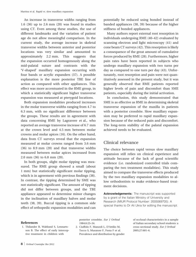
Table 2 reports descriptive statistics and pair-
wise comparison for T0 and T1 dental mea-
surements. The appliance produced molar
expansion at both cusp and apex levels in both
A
B
C
D
Fig. 3. Localization of skeletal landmarks on both coronaland axial planes. (A) Assessment of the anterior expansion;(B) assessment of posterior expansion; (C) assessment ofpterygoid expansion; (D) assessment of molar expansion andtipping
Orthod Craniofac Res 2012 5
Martina et al. Rapid vs. slow maxillary expansion
groups. In the SME group, molar tipping was
not statistically significant (0.3 ± 0.9 mm), while
in the RME group, there was negligible molar
tipping (1.0 ± 1.2 mm, p < 0.005). The expansion
measured at molar apices was significantly
lower in the RME group than in SME group
(p = 0.02).
Discussion
This study aimed to compare the skeletal and
dento-alveolar effects of two palatal expansion
procedures, RME and SME. To improve the pre-
cision of landmark identification and reduce the
radiation exposure of the patients a low-dose CT
protocol was used for research purposes (21).
Thus, a comparison between the two expansion
modalities was possible using skeletal landmarks
determined in three dimensions with much
improved reproducibility and accuracy in com-
parison with posteroanterior radiographs (24),
commonly used in previous research.
A two-band palatal expander was applied to
perform the expansion. This appliance has been
shown to be as effective as a four-band expander
in increasing the transverse widths of maxillae in
the long term (25, 26) and produces less patient
discomfort with easier clinical management.
In this study, patients younger than 13 years
were recruited, because the growth activity of the
palatal suture has been reported to reduce around
14 years of age (27).
All patients were subjected to CT imaging
before expansion and 7 months after initial acti-
vation of the appliances. This period was chosen to
Fig. 4. Diagram of patient flowthrough the trial.
6 Orthod Craniofac Res 2012
Martina et al. Rapid vs. slow maxillary expansion
obtain proper remineralization of the mid-palatal
suture and to reduce the risk of relapse (28, 29).
In both experimental groups, posterior crossbite
was successfully treated, and a significant increase
in themaxillary transverse widths of about 2.2 mm
was obtained. The amount of palatal expansion did
not differ significantly between the two investi-
gated groups and was similar to previous findings
(15, 20, 30). Nevertheless, the different imaging
methodologies used in previously published stud-
ies (lateral radiograph and CT) as well as the use of
different landmarks do not allow for direct com-
parison of data between studies.
In a meta-analysis, Lagravere et al. examined
clinical trials using 2D cephalometric analysis to
evaluate the skeletal changes produced by RME
(16). A pooled increase in the intermaxillary width
of 1.88 mm was reported. Some of the studies
analyzed (8, 25, 31–34) included subjects older
than 14 years, that is, with reduced sutural growth
activity (27). This might affect the amount of
expansion reported in the meta-analysis (35).
Table 1. Descriptive statistics and
pairwise comparisons for skeletal
transverse changes measured in both
groups
RME (n = 14) vs. SME (n = 12) skeletal transverse changes
Skeletal
transverse
measurements Group
T0
(mean ±
SD)
T1
(mean ±
SD) T1–T0 SD
95%
Confidence
interval
Anterior
expansion (mm)
SME 4.7 ± 1.9 6.6 ± 2.1 1.9 1.3** 1.0–2.1
RME 5.8 ± 3.8 8.2 ± 4.4 2.5 1.5** 1.6–3.3
Total 2.2 1.4
Posterior
expansion (mm)
SME 26.3 ± 2.2 28.2 ± 2.6 1.9 1.0** 1.3–2.5
RME 26.2 ± 2.3 28.6 ± 2.6 2.4 0.9** 1.8–2.9
Total 2.2 0.9
Pterygoid
expansion (mm)
SME 28.0 ± 2.1 28.6 ± 2.1 0.6" 0.6* 0.2–1.0
RME 28.0 ± 3.7 29.2 ± 4.2 1.2" 0.9** 0.7–1.7
Total 0.9 0.8
Significant T1–T0 within-group differences are reported with asterisks (Significance level:*p < 0.05, **p < 0.001)."Significant differences between groups (slow maxillary expansion (SME) vs. rapid max-illary expansion (RME)). Values are in mm.
Table 2. Descriptive statistics and
pairwise comparisons for dental trans-
verse changes measured in both
groups
Dental
transverse
measurements Group
T0
(mean ±
SD)
T1
(mean ±
SD)
T1–T0
mean
changes SD
95%
Confidence
interval
Cr-Cl (mm) SME 37.2 ± 3.4 43.6 ± 4.5 6.3 2.1*** 5.0–7.7
RME 37.3 ± 1.8 43.0 ± 2.4 5.7 1.6*** 4.8–6.7
Total 6.0 1.8
Ar-Al (mm) SME 28.5 ± 3.0 34.5 ± 3.5 6.0 1.7*** 4.9–7.0
RME 28.6 ± 2.3 33.4 ± 2.6 4.7 1.2*** 4.1–5.4
Total 5.3 1.5
Molar
tipping (mm)
SME 8.8 ± 3.9 9.1 ± 4.1 0.3 0.9NS 0.2–0.9
RME 8.6 ± 2.4 9.6 ± 2.6 1.0 1.2* 0.3–1.7
Total 0.7 1.1
Significant T1–T0 within-group differences are reported with asterisks (Significance level:*p < 0.05, **p < 0.005, ***p < 0.001, NS=not statistically significant). Values are in mm.
SME, slow maxillary expansion; RME, rapid maxillary expansion.
Orthod Craniofac Res 2012 7
Martina et al. Rapid vs. slow maxillary expansion
An increase in transverse widths ranging from
1.6 (36) up to 2.6 mm (20) was found in studies
using CT. Even among these studies, the use of
different landmarks and the variation of patient
age do not allow meaningful comparison. In the
current study, the average increase in skeletal
transverse widths between anterior and posterior
locations was very similar and amounted to
approximately 2.2 mm. This suggests that
the expansion occurred homogenously along the
mid-palatal suture and contrasts with the
#V-shaped! maxillary expansion occurring with
four bands or acrylic expanders (37). A possible
explanation is the more posterior TBE line of
action as compared with other appliances. This
effect was more accentuated in the RME group, in
which a statistically significant higher transverse
expansion was measured at pterygoid locations.
Both expansion modalities produced increases
in the molar transverse widths ranging from 4.7 to
6.3 mm, with no significant difference between
the groups. These results are in agreement with
data concerning RME by Lagravere et al., who
reported an average transverse increase of 6.7 mm
at the crown level and 4.5 mm between molar
crowns and molar apices (16). On the other hand,
data from CT surveys reveal that the expansion
measured at molar crowns ranged from 3.6 mm
(36) to 8.9 mm (20) and that transverse widths
measured between molar apices increased from
2.0 mm (36) to 6.8 mm (20).
In both groups, slight molar tipping was mea-
sured. The RME group showed a small (about
1 mm) but statistically significant molar tipping,
which is in agreement with previous findings (38).
In contrast, the tipping determined by SME was
not statistically significant. The amount of tipping
did not differ between groups, and the TBE
appliance appeared to determine minor changes
in the inclination of maxillary halves and molar
teeth (38, 39). Buccal tipping is a common side
effect of orthopedic expansion modalities and can
potentially be reduced using bonded instead of
banded appliances (38, 39) because of the higher
stiffness of bonded appliances.
Many authors report external root resorption in
individuals undergoing RME (40–42) evaluated by
scanning electron and light microscopy (41) and
cone beamCT surveys (42). This resorption is likely
a consequence of the great amount of cumulative
forces produced by RME (28). Furthermore, higher
pain rates have been reported in subjects who
undergo maxillary expansion with two turns per
day as compared to one turn per day (43). Unfor-
tunately, root resorption and pain were not quan-
titatively assessed in the present study, but it was
generally observed that RME patients reported
higher levels of pain and discomfort than SME
patients, especially during the initial activation.
In conclusion, this study demonstrated that
SME is as effective as RME in determining skeletal
transverse expansion of the maxilla in patients
with a posterior crossbite. Slow maxillary expan-
sion may be preferred to rapid maxillary expan-
sion because of the reduced pain and discomfort.
The long-term stability of the palatal expansion
achieved needs to be evaluated.
Clinical relevance
The choice between rapid versus slow maxillary
expansion still relies on clinical experience and
attitude because of the lack of good scientific
evidence (i.e. randomized controlled trials com-
paring the two treatment modalities). This study
aimed to compare the transverse effects produced
by the two maxillary expansion modalities to al-
low orthodontists to make evidence-based treat-
ment decisions.
Acknowledgements: The manuscript was supportedby a grant of the Italian Ministry of University andResearch (MIUR Protocol Number: 2005069705). Aspecial thanks to Dr Ali Ukra for editing the manuscript.
References1. Thilander B, Wahlund S, Lennarts-
son B. The effect of early intercep-
tive treatment in children with
posterior crossbite. Eur J Orthod
1984;6:25–34.
2. Ciuffolo F, Manzoli L, D!Attilio M,
Tecco S, Muratore F, Festa F et al.
Prevalence and distribution by gender
of occlusal characteristics in a sample
of Italian secondary school students: a
cross-sectional study. Eur J Orthod
2005;27:601–6.
8 Orthod Craniofac Res 2012
Martina et al. Rapid vs. slow maxillary expansion
3. Garrett BJ, Caruso JM, Rungcha-
rassaeng K, Farrage JR, Kim JS, Taylor
GD. Skeletal effects to the maxilla
after rapid maxillary expansion as-
sessed with cone-beam computed
tomography. Am J Orthod Dentofacial
Orthop 2008;134:8–9.
4. Baccetti T, Mucedero M, Leonardi M,
Cozza P. Interceptive treatment of
palatal impaction of maxillary canines
with rapid maxillary expansion: a
randomized clinical trial. Am J Orthod
Dentofacial Orthop 2009;136:657–61.
5. Kiki A, Kilic N, Oktay H. Condylar
asymmetry in bilateral posterior
crossbite patients. Angle Orthod
2007;77:77–81.
6. Andrade AS, Gameiro GH, Derossi M,
Gaviao MB. Posterior crossbite and
functional changes. A systematic re-
view. Angle Orthod 2009;79:380–6.
7. Hass AJ. Palatal expansion: just the
beginning of dentofacial orthopedics.
Am J Orthod Dentofacial Orthop
1970;57:219–55.
8. Asanza S, Cisneros GJ, Nieberg LG.
Comparison of Hyrax and bonded
expansion appliances. Angle Orthod
1997;67:15–22.
9. Huynh T, Kennedy DB, Joondeph DR,
Bollen AM. Treatment response and
stability of slow maxillary expansion
using Haas, hyrax, and quad-helix
appliances: a retrospective study. Am
J Orthod Dentofacial Orthop 2009;136:
331–9.
10. Mutinelli S, Cozzani M, Manfredi M,
Bee M, Siciliani G. Dental arch chan-
ges following rapid maxillary expan-
sion. Eur J Orthod 2008;30:469–76.
11. Marini I, BonettiGA,Achilli V, SalemiG.
A photogrammetric technique for the
analysis of palatal three-dimensional
changes during rapid maxillary expan-
sion. Eur J Orthod 2007;29:26–30.
12. Cao Y, Zhou Y, Song Y, Vanarsdall RL
Jr. Cephalometric study of slow max-
illary expansion in adults. Am J
Orthod Dentofacial Orthop 2009;136:
348–54.
13. Gracco A, Malaguti A, Lombardo L,
Mazzoli A, Raffaeli R. Palatal volume
following rapid maxillary expansion
in mixed dentition. Angle Orthod
2010;80:153–9.
14. Schiffman PH, Tuncay OC. Maxillary
expansion: a meta analysis. Clin Or-
thod Res 2001;4:86–96.
15. Lagravere MO, Major PW, Flores-Mir
C. Long-term skeletal changes with
rapid maxillary expansion: a system-
atic review. Angle Orthod
2005;75:1046–52.
16. Lagravere MO, Heo G, Major PW,
Flores-Mir C. Metaanalysis of imme-
diate changes with rapid maxillary
expansion treatment. J Am Dent Assoc
2006;137:44–53.
17. Diederichs CG, Engelke WG, Richter B,
Hermann KP, Oestmann JW. Must
radiation dose for CT of the maxilla and
mandible be higher than that for con-
ventionalpanoramic radiography?AJNR
Am J Neuroradiol 1996;17:1758–60.
18. Mozzo P, Procacci C, Tacconi A,
Tinazzi Martini P, Bergamo Adnreis
IA. A new volumetric CT machine for
dental imaging based on the cone-
beam technique: preliminary results.
Eur Radiol 1998;8:1558–64.
19. Nakajima A, Sameshima GT, Arai Y,
Homme Y, Shimizu N, Dougherty H
Sr. Two and three-dimensional
orthodontic imaging using limited
con beam-computed tomography.
Angle Orthod 2005;75:895–903.
20. Garib DG, Henriques JF, Janson G,
Freitas MR, Coelho RA. Rapid maxil-
lary expansion – tooth tissue-borne
versus tooth-borne expanders: a
computed tomography evaluation of
dentoskeletal effects. Angle Orthod
2005;75:548–57.
21. Matarese G, Portelli M, Mazza M,
Militi A, Nucera R, Gatto E et al.
Evaluation of skin dose in a low dose
spiral CT protocol. Eur J Paediatr
Dent 2006;7:77–80.
22. Ballanti F, Lione R, Fanucci E, Franchi
L, Baccetti T, Cozza P. Immediate and
post-retention effects of rapid maxil-
lary expansion investigated by com-
puted tomography in growing
patients. Angle Orthod 2009;79:24–9.
23. Ballanti F, Lione R, Baccetti T, Franchi
L, Cozza P. Treatment and posttreat-
ment skeletal effects of rapid
maxillary expansion investigated with
low-dose computed tomography in
growing subjects. Am J Orthod
Dentofacial Orthop 2010;138:311–7.
24. Leonardi R, Annunziata A, Caltabiano
M. Landmark identification error in
posteroanterior cephalometric radi-
ography. A systematic review. Angle
Orthod 2008;78:761–5.
25. Lamparski DG Jr, Rinchuse DJ, Close
JM, Sciote JJ. Comparison of skeletal
and dental changes between 2-point
and 4-point rapid palatal expanders.
Am J Orthod Dentofacial Orthop
2003;123:321–8.
26. Davidovitch M, Efstathiou S, Sarne O,
Vardimon AD. Skeletal and dental
response to rapid maxillary expansion
with 2- versus 4-band appliances.
Am J Orthod Dentofacial Orthop 2005;
127:483–92.
27. Melsen B. Palatal growth studied on
human autopsy material. A histologic
microradiographic study. Am J Orthod
1975;68:42–54.
28. Isaacson RJ, Wood JL, Ingram AH.
Forces produces by rapid maxillary
expansion. Angle Orthod 1964;34:
256–70.
29. Ekstrom C, Henrikson CO, Jensen R.
Mineralization in the midpalatal
suture after orthodontic expansion.
Am J Orthod 1977;71:449–55.
30. Kartalian A, Gohl E, Adamian M,
Enciso R. Cone-beam computerized
tomography evaluation of the
maxillary dentoskeletal complex
after rapid palatal expansion. Am J
Orthod Dentofacial Orthop 2010;138:
486–92.
31. Almeida G, Capeloza Filho L, Trinid-
ade ASJ. Rapid maxillary expansion: a
prospective study. Ortodontia
1999;32:45–56.
32. Kawakami RY, Henriques JFC, Pinzan
A, de Freitas MR, Janson G. Compar-
ison of dentoskeletal effects produced
by two types of rapid maxillary
expansion appliances by means of
lateral cephalometric evaluation.
Ortodontia 1999;32:8–27.
33. Faltin KJ, Moscatiello VA, Barrios EC.
Faltin Jr!s palatal expander: dentofa-
cial changes resulting from rapid
maxillary expansion. Rev Dent Press
Ortodont Ortopedi Facial 1999;4:5–13.
34. Mazziero ET, Henriques JFC, Freitas
MR. Study of frontal cephalometric
dentoskeletal changes after the rapid
maxillary expansion. Ortodontia
1996;29:31–42.
35. Baccetti T, Franchi L, Cameron CG,
McNamara JA Jr. Treatment timing
for rapid maxillary expansion. Angle
Orthod 2001;7:343–50.
36. Podesser B, Williams S, Crismani AG,
Bantleon HP. Evaluation of the effects
Orthod Craniofac Res 2012 9
Martina et al. Rapid vs. slow maxillary expansion
of rapid maxillary expansion in
growing children using computer
tomography scanning: a pilot study.
Eur J Orthod 2007;29:37–44.
37. Wertz R, Dreskin M. Midpalatal suture
opening: a normative study. Am J
Orthod 1977;71:367–81.
38. Kilic N, Kiki A, Oktay H. A comparison
of dentoalveolar inclination treated by
two palatal expanders. Eur J Orthod
2008;30:67–72.
39. Olmez H, Akin E, Karacay S. Multito-
mographic evaluation of the dental
effects of two different rapid palatal
expansion appliances. Eur J Orthod
2007;29:379–85.
40. Barber AF, Sims MR. Rapid maxillary
expansion and external root resorp-
tion in man: a scanning electron
microscope study. Am J Orthod
1981;79:630–52.
41. Langford SR, Sims MR. Root surface
resorption, repair, and periodontal
attachment following rapid maxillary
expansion in man. Am J Orthod
1982;81:108–15.
42. Baysal A, Karadede I, Hekimoglu S,
Ucar F, Ozer T, Veli I et al. Evalua-
tion of root resorption following ra-
pid maxillary expansion using cone-
beam computed tomography. Angle
Orthod. 2011; doi 10.2319/060411-
367.1.
43. Needleman HL, Hoang CD, Allred E,
Hertzberg J, Berde C. Reports of pain
by children undergoing rapid palatal
expansion. Pediatr Dent 2000;22:
221–6.
10 Orthod Craniofac Res 2012
Martina et al. Rapid vs. slow maxillary expansion
Related Documents

![Vertical and Transverse Management with Transpalatal …...on the first maxillary molar’s eruption, and DeBerardinis et al. [9] reported less posterior control and more open bite](https://static.cupdf.com/doc/110x72/601f83d47a99bc7c89086bb9/vertical-and-transverse-management-with-transpalatal-on-the-first-maxillary.jpg)