9CNW000146 Transformer bushings BRIT-90-35-200/1000 with RIP insulation voltage class 35 kV Operation manual GKSL 680205.021 RE Revision 4

Welcome message from author
This document is posted to help you gain knowledge. Please leave a comment to let me know what you think about it! Share it to your friends and learn new things together.
Transcript

9CNW000146
Transformer bushings
BRIT-90-35-200/1000
with RIP insulation
voltage class 35 kV
Operation manual
GKSL 680205.021 RE
Revision 4
TRANSFORMER BUSHINGS BRIT-90-35-200/1000 WITH RIP INSULATION, VOLTAGE CLASS 35 KV
Safety information
Keep this instruction available to those responsible for the installation, maintenance, and operation of the bushing.
The installation, operation, and maintenance of a bushing present numerous potential unsafe conditions,
including, but not limited to, the following:
■ High pressures
■ Lethal voltages
■ Moving machinery
■ Heavy components
■ Slip, stumble, or fall
Specialized procedures and instructions are required and must be adhered to when
working on such apparatus. Failure to follow the instructions could result in severe
personal injury, death, and/or product or property damage.
Additionally, all applicable safety procedures such as regional or local safety rules and regulations, safe working
practices, and good judgement must be used by the
personnel when installing, operating, maintaining and/or disposing such equipment.
Safety, as defined in this instruction, involves two conditions:
1. Personal injury or death.
2. Product or property damage (includes damage to the bushing or other property,
and reduced bushing life).
Safety notations are intended to alert personnel of possible personal injury, death or property damage. They have
been inserted in the instructional text prior to the step in which the condition is cited.
The safety conditions are headed by one of the three hazard intensity levels which are defined as follows:
DANGER:
Immediate hazard which will result in severe personal injury, death, or property damage.
WARNING: Hazard or unsafe practice which could result in severe personal injury, death, or property damage.
CAUTION: Hazard or unsafe practice which could result in minor personal injury, or property damage.
TRANSFORMER BUSHINGS BRIT-90-35-200/1000 WITH RIP INSULATION, VOLTAGE CLASS 35 KV
Table of Content
1. General .......................................................................................................................................................... 5
2. Purpose ......................................................................................................................................................... 5
3. Technical data ............................................................................................................................................... 5
4. Design ........................................................................................................................................................... 6
5. Marking .......................................................................................................................................................... 7
6. Packaging, transportation and storage ...................................................................................................... 7
6.1. Shipment ............................................................................................................................................. 7
6.2. Storage rules ....................................................................................................................................... 7
6.3. Proceeding after inexpert storage ....................................................................................................... 8
7. Installation .................................................................................................................................................... 8
7.1. Handling .............................................................................................................................................. 8
7.2. Installation on the transformer ............................................................................................................. 8
7.3. Cleaning the bushing surfaces and interfaces ..................................................................................... 8
7.4. Tightening order and tightening torques .............................................................................................. 9
7.5. Grounding the flange ......................................................................................................................... 10
7.6. Evacuating the transformer ............................................................................................................... 10
8. Measurements after installation ............................................................................................................... 10
9. Recommended maintenance and supervision ........................................................................................ 10
10. Testing ......................................................................................................................................................... 10
10.1. General ….. ....................................................................................................................................... 10
10.2. Capacitance C1 and tgδ1 measurements ............................................................................................ 11
10.3. Measuring equipment ........................................................................................................................ 12
10.3.1. Measuring bridge ............................................................................................................... 12
10.3.2. Power source ..................................................................................................................... 12
10.4. Installation and connection of the bridge ........................................................................................... 13
10.5. Measurement procedure ................................................................................................................... 13
10.6. Analysis of test results ....................................................................................................................... 13
11. Disposal ...................................................................................................................................................... 13
12. Scope of delivery ........................................................................................................................................ 14
13. Manufacturer ‘s address ............................................................................................................................ 14
TRANSFORMER BUSHINGS BRIT-90-35-200/1000 WITH RIP INSULATION, VOLTAGE CLASS 35 KV
General
The requirements of this instruction apply to 110 kV transformer bushings type BRIT-90-35-200/1000 with solid
RIP-insulation. This manual is designed for operational and maintenance personnel of power stations and power
network and installation companies’ staff. The manual provides basic instructions for installation and maintenance
of this type of bushings. The manual does not cover any repair aspects. If a bushing was damaged during
transportation, installation or usage, you should contact to Hitachi Energy Ltd for repair and retesting.
Purpose
Bushings with solid RIP-insulation (resin impregnated paper) are insulators used for getting out high voltage from
a transformer tank and are structurally independent devices. These bushings are intended for use in conditions
of climate O category 1 (according to GOST15150-69).
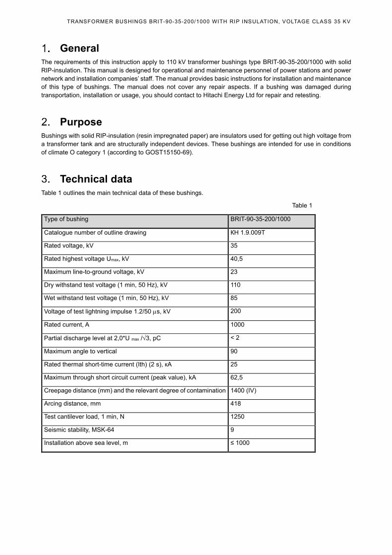
Technical data
Table 1 outlines the main technical data of these bushings.
Table 1
Type of bushing BRIT-90-35-200/1000
Catalogue number of outline drawing КН 1.9.009T
Rated voltage, kV 35
Rated highest voltage Umax, kV 40,5
Maximum line-to-ground voltage, kV 23
Dry withstand test voltage (1 min, 50 Hz), kV 110
Wet withstand test voltage (1 min, 50 Hz), kV 85
Voltage of test lightning impulse 1.2/50 s, kV 200
Rated current, A 1000
Partial discharge level at 2,0*U max /3, pC < 2
Maximum angle to vertical 90
Rated thermal short-time current (Ith) (2 s), кА 25
Maximum through short circuit current (peak value), kA 62,5
Creepage distance (mm) and the relevant degree of contamination 1400 (IV)
Arcing distance, mm 418
Test cantilever load, 1 min, N 1250
Seismic stability, MSK-64 9
Installation above sea level, m ≤ 1000
TRANSFORMER BUSHINGS BRIT-90-35-200/1000 WITH RIP INSULATION, VOLTAGE CLASS 35 KV
Design
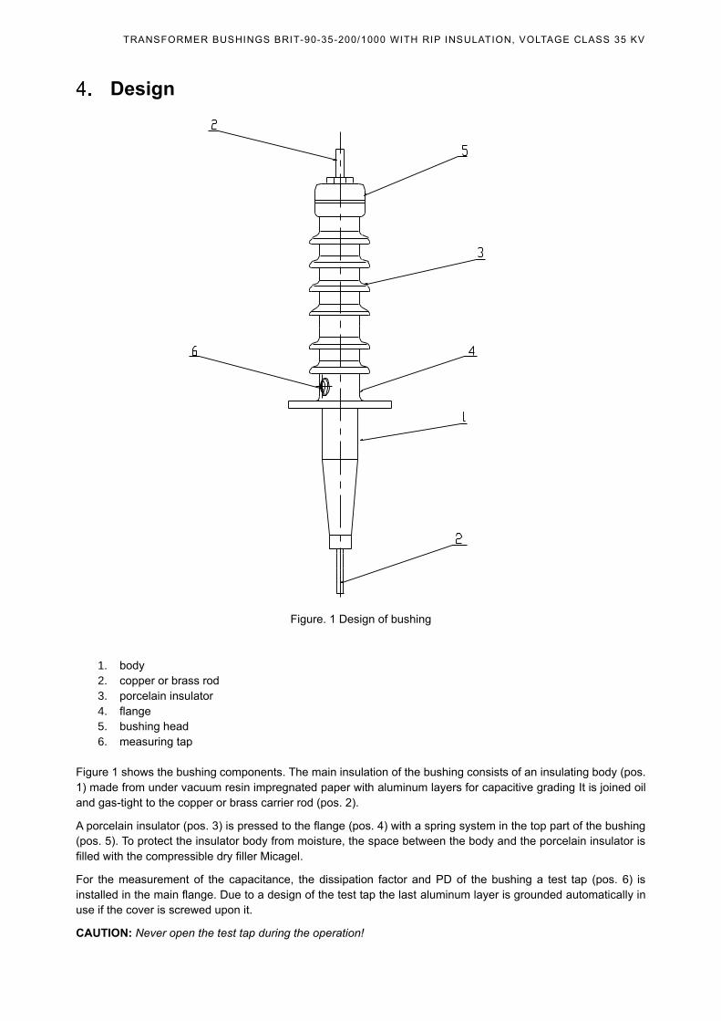
Figure. 1 Design of bushing
1. body
2. copper or brass rod
3. porcelain insulator
4. flange
5. bushing head
6. measuring tap
Figure 1 shows the bushing components. The main insulation of the bushing consists of an insulating body (pos.
1) made from under vacuum resin impregnated paper with aluminum layers for capacitive grading It is joined oil
and gas-tight to the copper or brass carrier rod (pos. 2).
A porcelain insulator (pos. 3) is pressed to the flange (pos. 4) with a spring system in the top part of the bushing
(pos. 5). To protect the insulator body from moisture, the space between the body and the porcelain insulator is
filled with the compressible dry filler Micagel.
For the measurement of the capacitance, the dissipation factor and PD of the bushing a test tap (pos. 6) is
installed in the main flange. Due to a design of the test tap the last aluminum layer is grounded automatically in
use if the cover is screwed upon it.
CAUTION: Never open the test tap during the operation!
TRANSFORMER BUSHINGS BRIT-90-35-200/1000 WITH RIP INSULATION, VOLTAGE CLASS 35 KV
Marking
On every bushing flange there is a designation plate with following information:
• manufacturer’s trade mark;
• country;
• the bushing’s identifying code;
• dimensional drawing number;
• production serial number;
• voltage and current rating;
• weight;
• maximum installation angle to vertical;
• C1 and tgδ1;
• C2 and tgδ2.
Packaging, transportation and storage
6.1. Shipment
Bushings are transported in wooden boxes rigidly fixed with elastic packing cradles. The top of the box is marked
with “Top”. Bushings are shipped and stored horizontally. The low part of bushing is protected from moisture by a
plastic case with a silica gel bag inside.
While storing plastic cases and silica gel bags are checked for consistency once in six months. A change of
indicating silica gel color from blue to pink points at its silica gel’s being damp. In this case the whole silica gel
must be changed.
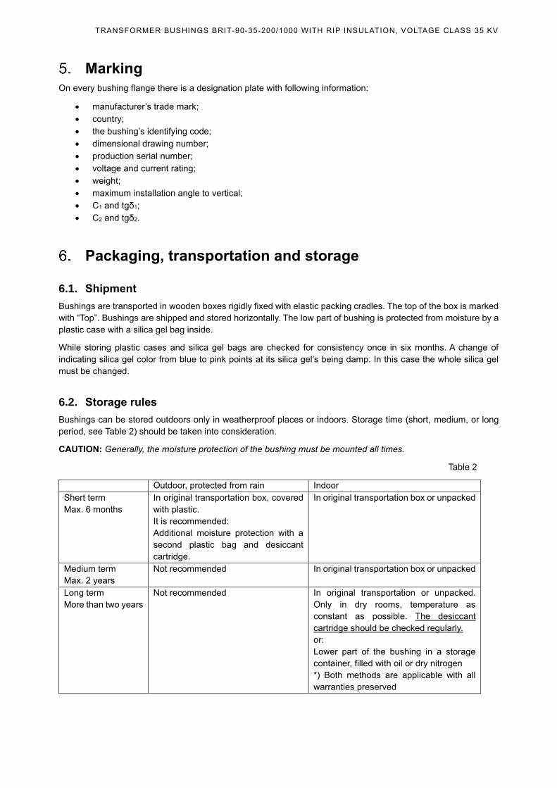
6.2. Storage rules
Bushings can be stored outdoors only in weatherproof places or indoors. Storage time (short, medium, or long
period, see Table 2) should be taken into consideration.
CAUTION: Generally, the moisture protection of the bushing must be mounted all times.
Table 2
Outdoor, protected from rain Indoor
Shert term
Max. 6 months
In original transportation box, covered
with plastic.
It is recommended:
Additional moisture protection with a
second plastic bag and desiccant
cartridge.
In original transportation box or unpacked
Medium term
Max. 2 years
Not recommended In original transportation box or unpacked
Long term
More than two years
Not recommended In original transportation or unpacked.
Only in dry rooms, temperature as
constant as possible. The desiccant
cartridge should be checked regularly.
or:
Lower part of the bushing in a storage
container, filled with oil or dry nitrogen
*) Both methods are applicable with all
warranties preserved
TRANSFORMER BUSHINGS BRIT-90-35-200/1000 WITH RIP INSULATION, VOLTAGE CLASS 35 KV
6.3. Proceeding after inexpert storage
If there is suspicious the weather storage conditions don’t conform to the table above, it is possible, that humidity
has been got into the insulation by a diffusion process. This must be diagnosed by capacitance and power factor
(tg) measurement at about 10 kV between head and measuring tap. If the deviation of the power factor is more
of a test report value at 0,1 %, please contact Hitachi Energy, Russia for further information about the drying
procedure.
Installation
7.1. Handling
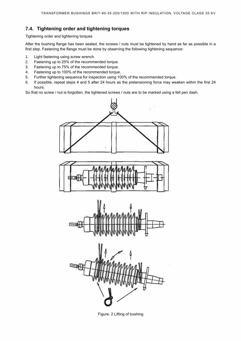
During unpacking be careful to avoid porcelain insulator damage. A sling and a lifting device (Figure 2) will be
required while taking the bushing out of the box. One end of the sling is put around the porcelain between the two
uppermost sheds. The other end is slung around the flange. If placed on the ground, the bushing shall be
supported at the same points as in the box.
Examine the bushing to make sure the porcelain insulator is undamaged, take off the plastic cover and make sure
that the body is undamaged too.
For bringing the bushing into vertical position the easiest this is done with two lifting gears and two textile slings.
One sling must be put around the flange and directly taken to one lifting gear. The other sling is fixed around the
two uppermost porcelain sheds and attached to the other lifting gear. With lifting gears, the bushing is first raised
horizontally and then the flange end is lowered.
CAUTION: The bushing should not be turned into vertical position with only one rope. The bushing can slip
through and fall down.
Another option for lifting a bushing into a vertical position is to use one crane. In this case instead of the crane
which used for lifting the flange side can be used another lifting gear, which hanged on the hook of the same
crane.
For lifting of a bushing at a certain angle with a single crane can be used a polyspast. For this one end of a sling
is fixed to the eye screw of the flange and another end through the polyspast is fixed to a hook of a crane. The
other sling is fixed around the two uppermost porcelain sheds and attached to the same lifting hook. The angle is
adjusting by the polyspast.
7.2. Installation on the transformer
The bushings type BRIT do not contain transformer oil and therefore can be mounted right after transporting or
storage without being kept upright for a certain period.
7.3. Cleaning the bushing surfaces and interfaces
The sealing faces on the transformer tank and at the bushing flange must be free from corrosion and
contamination and offer a high surface finish (max. Ra 3.2). Clean these sealing faces by soaking a lint-free cotton
cloth in the cleaning liquid and wiping them off.
Always make sure that the vent hole at the flange is not obstructed or closed e.g. by a flat seal.
The unshielded area of the bushing (insulating body at oil side) may not be scratched. If the lifting eyes at the
bottom of the flange protrude, they must be dismounted before tightening the flange. The fastening of the flange
must be designed in a way that no deformation may occur at the bushing flange. The support surface of the
transformer must have a flatness tolerance of max. 0.3 mm (no steps allowed).
Before the installation, the bushing must adapt to the environmental temperature to prevent condensation at the
bushing surface.
WARNING: Do not damage the sealing face!
TRANSFORMER BUSHINGS BRIT-90-35-200/1000 WITH RIP INSULATION, VOLTAGE CLASS 35 KV
7.4. Tightening order and tightening torques
Tightening order and tightening torques
After the bushing flange has been seated, the screws / nuts must be tightened by hand as far as possible in a
first step. Fastening the flange must be done by observing the following tightening sequence:
1. Light fastening using screw wrench.
2. Fastening up to 25% of the recommended torque.
3. Fastening up to 75% of the recommended torque.
4. Fastening up to 100% of the recommended torque.
5. Further tightening sequence for inspection using 100% of the recommended torque.
6. If possible, repeat steps 4 and 5 after 24 hours as the pretensioning force may weaken within the first 24
hours.
So that no screw / nut is forgotten, the tightened screws / nuts are to be marked using a felt pen dash.
Figure. 2 Lifting of bushing
TRANSFORMER BUSHINGS BRIT-90-35-200/1000 WITH RIP INSULATION, VOLTAGE CLASS 35 KV
7.5. Grounding the flange
DANGER: The flange of the bushing must always be ground by a safe earth connection (wire) after the
installation!
The bushings are provided with one or two threads M12 at the flange in order to ground the flange.
After tightening the bolts fixing the bushing to the transformer tank, the flange should be earthed. This prevents
electrical discharges between bushing flange and transformer tank during service. Apply a flexible cable between
the M12 earthing hole in the bushing flange and a corresponding connection point in the transformer. The
tightening force is 40 Nm.
7.6. Evacuating the transformer
Evacuating the transformer with the bushing installed is permitted. If the transformer oil is filled in under vacuum,
a subsequent deaeration at the bushing or the transformer dome is usually not necessary. If the transformer is
not evacuated, then the central inlet pipe must be deaerated using a plug screwed into the top of the upper
terminal
CAUTION: After deaeration of the central inlet pipe, it is necessary to check whether the plug is tightly screwed
into the deaeration hole.
The high voltage Un/3 should be applied to the bushing not earlier 12 hours after filling the transformer with
oil.
Measurements after installation
After installation of the bushing on the transformer С1 и tg1 measurement is recommended to compare with
values in a acceptance test report. A significant difference in the value of the capacity C1 from that specified in
the acceptance test report (more than 5%) may indicate damage (transport or during installation) and the
commissioning should not be put into operation.
A significant difference in the value of the capacity C1 from that specified in the acceptance test report (more than
5%) may indicate damage (transport or during installation) and the commissioning should not be put into
operation.
The essential difference between capacitance values C1 in the protocol from said acceptance tests (more than
5%) may indicate damage (for transport or during installation) and administered must not be put into operation.
Recommended maintenance and supervision
• Cleaning of insulator surface
• Measurement of capacitance and tan
• Thermovision (infraded camera) check for local overheating on connectors
Testing
10.1. General
Measurement of C1 and tgδ1 are carried out after the bushing was installed on the transformer or during a regular
check of the transformer.
The frequency of such measurements must be in accordance with local requirements.
WARNING: For diagnostic of the bushing insulation is used C1 and tgδ1. The recommended voltage for measuring
C1 and tgδ1 – 10 kV and C2 and tgδ2 – 1 kV.
TRANSFORMER BUSHINGS BRIT-90-35-200/1000 WITH RIP INSULATION, VOLTAGE CLASS 35 KV
The measurement of the resistance of the test tap must be used mega ohmmeter with the voltage not more than
1000 V DC.
It is not recommended to measure C2 and tgδ2 as the result of their measurement depends on environment
contamination and humidity.
Moreover, during operation condition, the outer layer is earthed. Consequently, the insulation between the outer
layer and the mounting flange are not subjected to an electrical field and thereby do not cause any dielectric heat
losses.
10.2. Capacitance C1 and tgδ1 measurements
First de-energize the transformer, then take the test tap cover off and connect the measuring equipment to it using
the test adapter, while the test power source is connected to the terminate plate of the bushing.
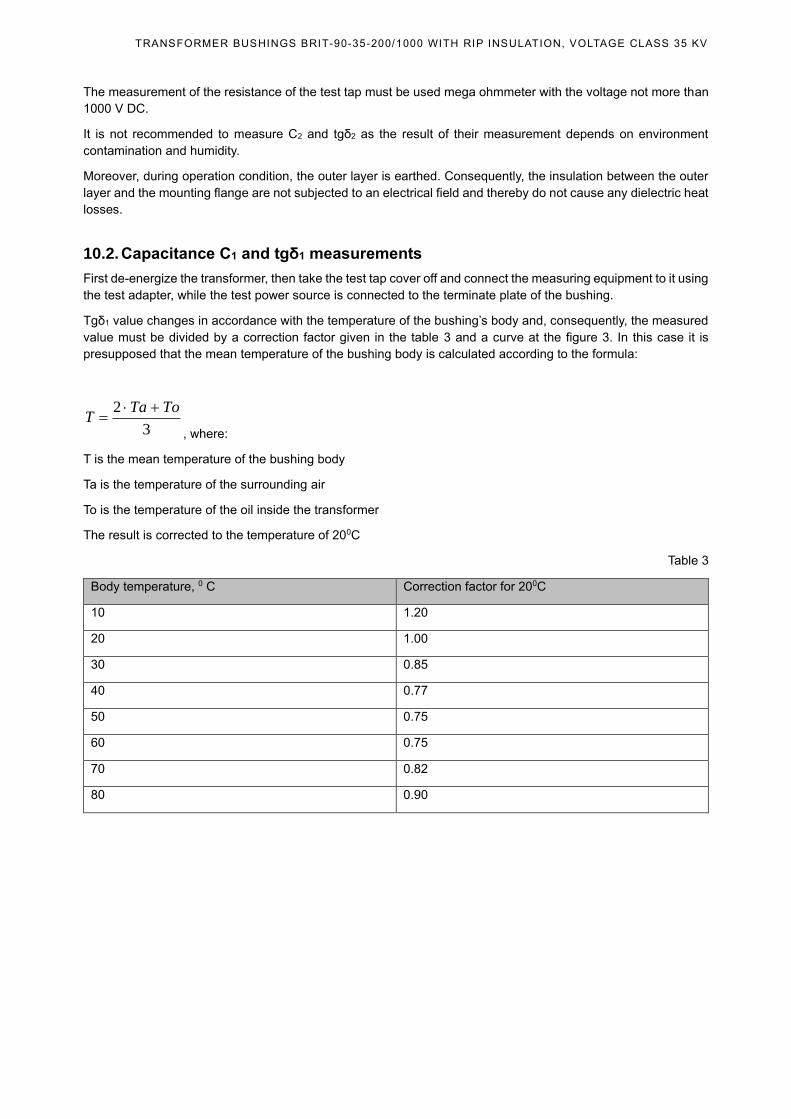
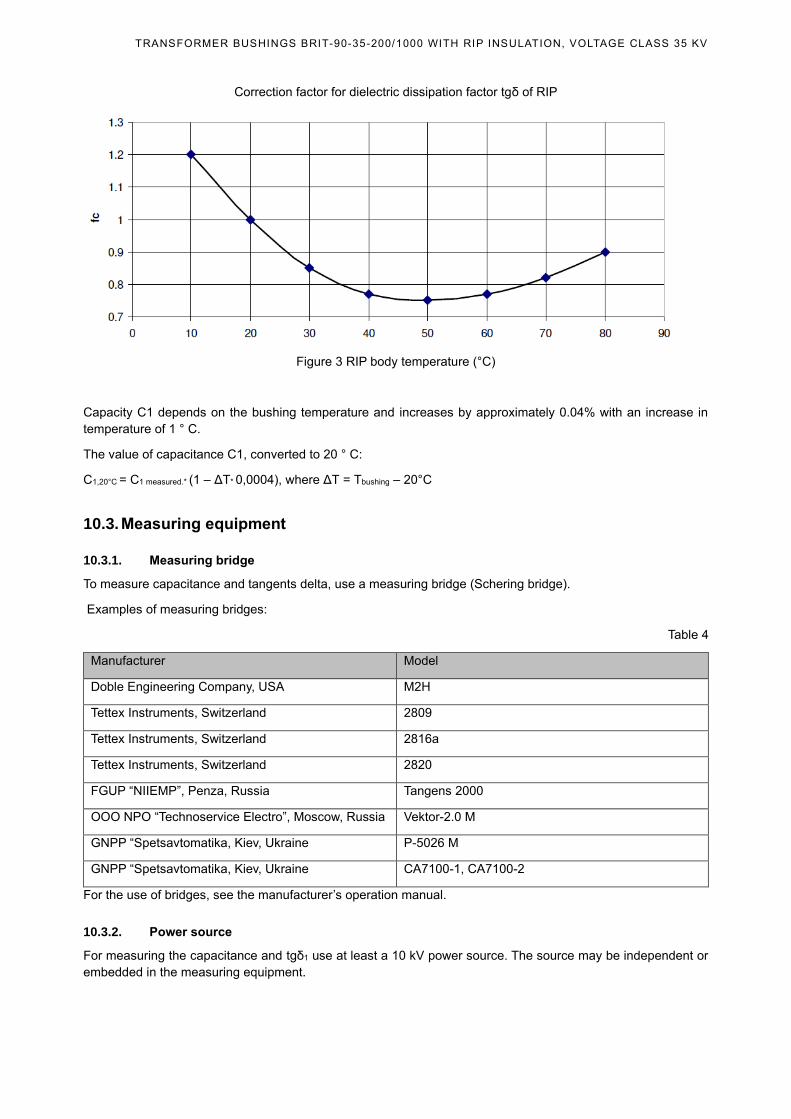
Tgδ1 value changes in accordance with the temperature of the bushing’s body and, consequently, the measured
value must be divided by a correction factor given in the table 3 and a curve at the figure 3. In this case it is
presupposed that the mean temperature of the bushing body is calculated according to the formula:
3
2 ToTaT
+=
, where:
T is the mean temperature of the bushing body
Ta is the temperature of the surrounding air
To is the temperature of the oil inside the transformer
The result is corrected to the temperature of 200C
Table 3
Body temperature, 0 C Correction factor for 200C
10 1.20
20 1.00
30 0.85
40 0.77
50 0.75
60 0.75
70 0.82
80 0.90
TRANSFORMER BUSHINGS BRIT-90-35-200/1000 WITH RIP INSULATION, VOLTAGE CLASS 35 KV
Correction factor for dielectric dissipation factor tgδ of RIP
Figure 3 RIP body temperature (°C)
Capacity C1 depends on the bushing temperature and increases by approximately 0.04% with an increase in
temperature of 1 ° C.
The value of capacitance C1, converted to 20 ° C:
С1,20°С = С1 measured.* (1 – ΔТ* 0,0004), where ΔТ = Тbushing – 20°С
10.3. Measuring equipment
10.3.1. Measuring bridge
To measure capacitance and tangents delta, use a measuring bridge (Schering bridge).
Examples of measuring bridges:
Table 4
Manufacturer Model
Doble Engineering Company, USA M2H
Tettex Instruments, Switzerland 2809
Tettex Instruments, Switzerland 2816a
Tettex Instruments, Switzerland 2820
FGUP “NIIEMP”, Penza, Russia Tangens 2000
OOO NPO “Technoservice Electro”, Moscow, Russia Vektor-2.0 M
GNPP “Spetsavtomatika, Kiev, Ukraine P-5026 M
GNPP “Spetsavtomatika, Kiev, Ukraine CA7100-1, CA7100-2
For the use of bridges, see the manufacturer’s operation manual.
10.3.2. Power source
For measuring the capacitance and tgδ1 use at least a 10 kV power source. The source may be independent or
embedded in the measuring equipment.
TRANSFORMER BUSHINGS BRIT-90-35-200/1000 WITH RIP INSULATION, VOLTAGE CLASS 35 KV
10.4. Installation and connection of the bridge
DANGER: Make sure that the transformer is off and out of service.
For safe and reduce influence of interference, short circuit all the transformer winding. Ground the windings that
are not connected to the bushing being tested.
Connect the measuring bridge to the test tap as required in the relevant operation manual.
Depending on which insulator is checked, connect the power source (test voltage) to the terminate plate or the
test tap.
Testing wires must be as short as possible and must not contact grounded objects.
The test tap must be clean and dry.
10.5. Measurement procedure
Connect the grounding terminal of the bridge to the transformer grounding terminal. The flange of the not installed
bushing on the transformer and to be measured, must be grounded.
Before putting the bushing into service, carry out a measurement of dissipation factor tgδ1 and capacity C1 at the
voltage up to 10 kV in order to have a reference for later checks.
We recommend take this measurements step by step: 2, 4, 6, 8, 10 sequence. The measurement results should
be very close. Significant differences may indicate the influence of external interference on the measuring circuit
or poor contact in the measuring circuit, for example, in connection to the test tap terminal.
The measurement procedure must comply with the instructions for the measuring bridge.
On completion of measuring, remove the test adapter from the test tap and screw on the protective cover to
protect the test tap from moisture and contamination (in this case the test tap is grounded automatically).
CAUTION: The test tap must not be open during service or storage.
10.6. Analysis of test results
The measured and corrected tgδ1 value is compared with that in the routine test report.
A considerable difference of the capacitance C1 from a value of the test report (more 5%) may indicate a damage
(transportation- or assembly-caused), so such bushing must not be used.
A value C2 depends on the way the bushing is embedded into the transformer and is not used for diagnostic.
The value tg2 is also not used for bushing diagnostic (see section 10.1).
During operation, the insulation of the bushing is aging, as evidenced by an increase in the value of tg1.
In the operation input is aging insulation, as evidenced by the increase in the value tg * 1.
The limiting value of tg1. should not exceed 0.7%.
An increase in the capacity C1 during operation may indicate a breakdown of one or more layers of the bushing
insulation.
Upon reaching the limit value tg1. or increasing the capacity C1 by more than 5%, please contact Hitachi Energy
Ltd., Russia for recommendations on the possibility of further operation of the bushing.
The service life of the bushing is at least 30 years.
Disposal
After reaching the end of lifetime, this product has to be disposed correctly according to local laws and regulations.
All the contained substances and material should be recycled separately. The product as a whole and its individual
parts do not contain any toxins.
TRANSFORMER BUSHINGS BRIT-90-35-200/1000 WITH RIP INSULATION, VOLTAGE CLASS 35 KV
Nether breathing- nor skin protection nor any special precautions are required. Apply the common and appropriate
safety standards to prevent working accidents. In case of uncertainties please contact Hitachi Energy Ltd., Russia
for advanced information and instructions.
Scope of delivery
The scope of delivery of each bushing shall include documentation and components:
• Documentation
• Test report
• Operational manual
• Dimensional drawing
• Packing sheet
Components
• Test adapter (1 item)
• Terminate plate (as specified in the order).
Manufacturer ‘s address
If you have any question concerning the installation and use of these bushings, please contact the manufacturer
at the address:
Russia, 141371, Moscow region, Khotkovo-1, PO 8,
Tel. (495) 777 1616, ext. 1200.
E-mail: [email protected]
www.hitachienergy.com
Service center for high-voltage equipment of Hitachi Energy Ltd., Russia:
Address: 117997, Cheboksary city, Rechnikov square, 3
Tel.: +7(8352) 220-07-22.
E-mail: [email protected]
Related Documents