TRAINING MODULES FOR WATERWORKS PERSONNEL Special Knowledge 2.11 Simple surveying and technical drawing

Welcome message from author
This document is posted to help you gain knowledge. Please leave a comment to let me know what you think about it! Share it to your friends and learn new things together.
Transcript
TRAINING MODULESFOR
WATERWORKS PERSONNEL
Special Knowledge2.11
Simple surveying and technical drawing

83-7
Training modules for waterworks personnelin developing countries
Foreword
Even the greatest optimists are no longer sure that the goals of the UN "International DrinkingWater Supply and Sanitation Decade", set in 1977 in Mar del Plata, can be achieved by 1990.High population growth in theThird World combined with stagnating financial and personnelresources have led to modifications to the strategies in cooperation with developing coun-tries. A reorientation process has commenced which can be characterized by the followingcatchwords:- use of appropriate, simple and - if possible - low-cost technologies,- lowering of excessively high water-supply and disposal standards,- priority to optimal operation and maintenance, rather than new investments,- emphasis on institution-building and human resources development.Our training modules are an effort to translate the last two strategies into practice. Experiencehas shown that a standardized training system for waterworks personnel in developingcountries does not meet our partners' varying individual needs. But to prepare specificdocuments for each new project or compile them anewfrom existing materials on hand can-not be justified from the economic viewpoint. We have therefore opted for a flexible system oftraining modules which can be combined to suit the situation and needs of the target groupin each case, and thus put existing personnel in a position to optimally maintain and operatethe plant.The modules will primarily be used as guidelines and basic training aids by GTZ staff andGTZ consultants in institution-building and operation and maintenance projects. In themedium term, however, they could be used by local instructors, trainers, plant managersand operating personnel in their daily work, as check lists and working instructions.45 modules are presently available, each covering subject-specific knowledge and skillsrequired in individual areas of waterworks operations, preventive maintenance and repair.Different combinations of modules will be required for classroom work, exercises, and prac-tical application, to suit in each case the type of project, size of plant and the previous qualifi-cations and practical experience of potential users.Practical day-to-day use will of course generate hints on how to supplement or modify thetexts. In other words: this edition is by no means a finalized version. We hope to receive yourcritical comments on the modules so that they can be optimized over the course of time.Our grateful thanks are due to
Prof. Dr.-lng. H.P. HaugandIng.-Grad. H. Hack
for their committed coordination work and also to the following co-authorsfor preparing the modules:
Dipl.-lng. Beyene Wolde GabrielIng.-Grad. K. H. EngelIng.-Grad. H. HackIng.-Grad. H. HauserDipl.-lng. H. R. JolowiczK. Ph. Muller-OswaldIng.-Grad. B. RollmannDipl.-lng. K. SchnabelDr. W. Schneider
It is my sincere wish that these training modules will be put to successful use and will thussupport world-wide efforts in improving water supply and raising living standards.
Dr. Ing. Klaus ErbelHead of DivisionHydraulic Engineering,Water Resources DevelopmentEschborn, May 1987

Training modules for waterworks personnelin developing countries
Module2.11
Page
Title: Simple surveying and technical drawing
Table of contents:1 Appliances and instruments1.1 Instruments used to measure length1.2 Instruments used to measure levels1.3 Instruments used to measure angles2 Setting out of longitudinal sections (pegging out)3 Setting out of cross-sections5 Boning4 Representation of bodies5.1 Stereoscopic representation of perspective5.2 Rules for the representation of cross-sections5.3 Rules for the dimensioning of drawings5.4 Rules for the representation of threads5.5 Rules for the indication of surface finishes5.6 Rules for the indication of tolerances6 Representation of pipelines and other components
of water-supply systems6.1 Pipes6.2 Joints6.3 Valves6.4 Equalizers6.5 Accessories6.6 Pipe supports6.7 Hydrants7 Pipe lay-out plans8 Bibliography
Page2246991011121620262931
33333334353536363741
Revised:

Training modules for'waterworks personnelin developing countries
Module2.11
Page2
1 Appliances and instruments
1.1 Instruments used to measure length
In simple measurements of length, a metrestick, measuringrod, linen tape measure or rolled steel band is used. Greaterprecision is obtained with the use of invar tapes, opticaldistance measurement or electro-optical distance measurement.
Metresticks
77771
? 2 3 i.i I I * .iiiliiiimiiliiiilimliiiiliiiiliiiiliiiil
Positioning of the metrestick
Metresticks are foldingrules, usually made of wood.They have a length of oneor two metres and are gradu-ated along their completelength in centimetres andmillimetres. Since the
graduation begins at the metal-clasped ends of the rule,the end can be placed flush against the staff, peg etc.where measuring begins. If the distance to be measured islonger than two metres, care must be taken to measure ina straight line.
Measuring rods (staffs)
Rod 2 Rod 1
White Red
Two rods placed end-to-end
These are made of well-seasoned, knot-free pine orfir and are supplied inpairs. Each rod is 5 m longand is graduated only indecimetres. Centimetres ormillimetres have to be
measured off with a metrestick. Whole metres are paintedalternately red and white (or black and white).
Fluctuations to temperature have very little effect on theaccuracy of measuring rods. On the other hand, they aresusceptible to damp (the wood swells), and should thereforealways be kept in a dry place.
Revised:

Training modules for waterworks personnelin developing countries
Module2.11
Page3
Use of rods to measure length
Measuring is always carried out with two rods. One of thesebegins with a metre length marked in red, the other witha metre length marked in white. For convenience, the measuringprocess should always be started with the same rod, e.g.the "red" rod.
Care must be taken,always to measure the horizontal distancebetween two points and to avoid any lateral divergence fromthe line of measurement.
On horizontal, level sites the rods are simply placedend-to-end on the ground. At the starting point of themeasurement, the end of the rod must be placed preciselyagainst the middle of the peg (nail) or the middle of therange pole. .
When measuring distances along sloping ground, the "stepping-down" method is generally used. In this,- the measuring rodsare adjusted to the horizontal one after the other withthe aid,of a spirit level and the ends of two rods positionedexactly one above the other using a plumb line.
6Q
Measuring a distanceby stepping down
Horizontal measurementusing rods (staffs)
Measuring tapes
Measuring tapes or bands are made of steel or plastics in •varicjs lengths (20, .0, 50and 100 m). When not in use,the tape is kept rolled up in aframe or case. Coated steel bands
Measuring tape ' with a length of 20 metres are
Revised:

Training modules for waterworks personnelin developing countries
Module2.11
Page4
the most widely used. The tape is graduated in centimetres,the first decimetre additionally in millimetres. These tapesare calibrated at a temperature of +20°C and a tensile stressof 50 N. Frequent cleaning is important; steel bands mustbe carefully dried and lightly oiled to prevent rusting.
Measurement using tapes
Measuring tapes are most widely used to measure distanceson level ground which are not longer than the tape itself.On sloping ground, the unrolled tape must be held in sucha way that both ends are at the same level (i.e. the distancemeasured is horizontal). A certain sag of the ta.pe is unavoid-able and is already taken into account in its calibration.The tape should therefore be held neither too loosely nortoo taughtly (standard tension approx. 50 N). The end ofthe tape must be plumbed above the measuring point. Thisis in principle the same method as stepping down a slopewith a measuring rod, but the rod gives more accurate results.
Measuring with a tape Position of zero lineup a slope
1.2 Instruments used to measure levels
In the measurement of leveli ("levelling"), the verticaldistance in level between two points is measured. Depending
. on the required degree of accuracy and the distance betweenthe two points, various different appliances are used.
Hose level
This consists of a hose, 15 to 25 m long, with a water gauge(glass tube) inserted into each end. The hose is filled
Revised:

Training modules for waterworks personnelin developing countries
Module2.11
Page5
Water
Hose level
,with water and moved about so,that air can escape. The glasstubes are then sealed temporarily.with corks, so that no water islost during transport. In com-municating vessels, liquidsstand at the same vertical height.In application of this principle,the surface of the water in oneof the glass tubes is placed
against a point with a known level, and the corresponding .level of the other water surface marked on the structureor sight rail.
Levelling staff
A levelling staff is used to measure the vertical differencein level and the horizontal distance between two points,
.which should not be too far away from each other. A dressedboard with a length of several metres can be used as levellingstaff, but better is a purpose-made, graduated rod.
.The levelling staff is placed on'a point and adjusted with theaid of'a spirit level until itis horizontal. Using a verticalmeasuring rod,(perhaps a metre-stick), the level at the undersideof the levelling staff is ascer-tained, also the horizontaldistance; the end of the level- •
Levelling ling staff being plumbed.
Level
Levels are used to ascertain varying levels over greaterdistances. The instrument consists of a telescope whichcan be turned on a sub-structure (the "levelling head")round an axis which is vertical to.the telescope (supporting
Levelling staff
Revised:

gz Training modules for waterworks personnelin developing countries
Module2.11
Page
6
Collimationline Supporting
!—axis
Po cussingscrew„ ,Foot screw
Eye-piece
Fill-boxI__L__1 bubble
Level
axis). With the aid of the pill-box bubble on the levelling head,the supporting axis is adjusteduntil it ,is approximately ver-tical. A bubble tube is used toadjust the telescope (line ofcollimation) until it is horizon-tal. The greater majority oflevels used nowadays have adevice which is responsiblefor automatic horizontal adjust-ment of the collimation line
of the telescope. Such instruments (automatic or autoset levels)have no bubble tube.
1.3 Instruments used to measure angles
Setting out of right angles
A full circle is divided into 360° (degrees) or 400 gons.90°, or 100 gons, make a right angle. Right angles are setout on a site with the aid of a cross staff or prism square.If neither of these is available, right angles can also beset out by an application of Pythagoras' theorem.
Application of geometrical principles
According to Pythagoras' therorem,any triangle of which' the sidesare in the ratio 3 : 4 : 5 mustbe right-angled. Assuming thata right angle is to be set outat point A, first of all point Bis marked at a distance of 3 m
from point A. Then two measuring rods are positioned in sucha way at points A and B that a triangle with its sides inthe ratio 3 : 4 : 5 is formed. If two measuring tapes areavailable, the same technique is used, but the distancesincreased proportionately.
Revised:

(vjupZ Training modules for waterworks personnelin developing countries
Module2.11
Page
7
i v0I.—i\)_____>—.
i A
. .A site square is made by nailingboards together into a trianglewith its sides in a 3 : 4 : 5ratio. Site squares are used toset out and check the accuracyof right angles. A right, anglecan also be -obtained with theaid of an isosceles triangle:
Two equal distances, b = b 1,are measured from point A. PointC is established by holding two
• measuring tapes of equal length(a = a) each with one end at
points B and B' and moving them through an angle until theymeet.
Cross staff .A cross staff consists of atruncated cone-shaped metalbody screwed onto a metal staffapprox. 1.40 m long. The staffis pointed at its other end, sothat it can be pushed into theground. The head of the cross-staff has sets of slits, i.e.two arranged vertically one .above the other, in opposite
faces (diopter slits). They are positioned in such a waythat sight lines are formed which are perpendicular to eachother. -
When a right angle has to be set out, the cross staff isfirst set up at the appropriate point on the survey lineand adjusted, with the aid of the pill-box bubble fastenedto it,s until it is vertical. Then the instrument is turneduntil a staff set up some distance away along the survey
Diopter
Diopter planes
Revised:
Training modules for waterworks personnelin developing countries
Module
2.llPage
8
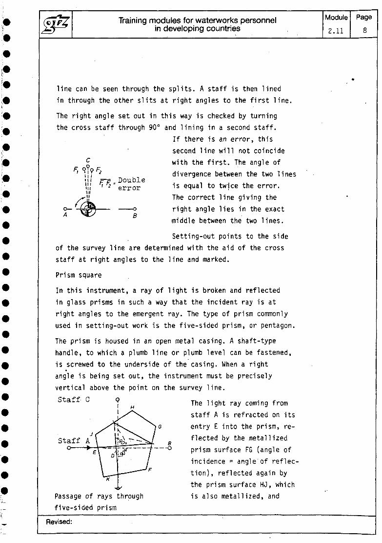
line can be seen through the splits. A staff is then linedin through the other slits at right angles to the first line.
The right angle set out in this way is checked by turningthe cross staff through 90° and lining in a second staff.
If there is an error, thissecond line will not coincide
£ with the first. The angle ofdivergence between the two linesis equal to twice the error.The correct line giving theright angle lies in the exactmiddle between the two lines.
IIIIIIIIIp-p _ Double,' 2 error
B
Setting-out points to the sideof the survey line are determined with the aid of the crossstaff at right angles to the line and marked.
Prism square
In th-is instrument, a ray of light is broken and reflectedin glass prisms in such a way that the incident ray is atright angles to the emergent ray. The type of prism commonlyused in setting-out work is the five-sided prism, or pentagon.
The prism is housed in an open metal casing. A shaft-typehandle, to which a plumb line or plumb level can be fastened,is screwed to the underside of the casing. When a rightangle is being set out, the instrument must be preciselyvertical above the point on the survey line.Staff C Q The 1ight ray conrjng from
staff A is refracted on itsentry E into the prism, re-flected by the metallizedprism surface FG (angle ofincidence = angle of reflec-tion), reflected again bythe prism surface HJ, whichis also metallized, and
K
Passage of rays throughfive-sided prism
Revised:

Training modules for waterworks personnelin developing countries
Module2.11
Page9
refracted again at its emergence in K, so that after emergencethe ray is at an angle of 90° to the direction of incidence.The eye sees staff A in the prism, above or below the prismstaff C. If staffs A and C form a straight line, the anglebetween points A, D and C is a right angle. .
Measurement of other angles
Other angles are measured with a magnetic compass, a prismdrum (Mexican be altered) or a level with horizontal circle.With the aid of a plumb bob, the level is set up exactlyabove the measuring point, and the measured angle read offthe 360° scale on the horizontal .'circle. A vertical circle'can also be provided for measurement of vertical angles.
2 Setting out of longitudinal sections (pegging out)
If work is being done on the axis, pegging must be carriedout .outside the area of work. A level peg H and number pegN are driven in at regular intervals, at the same distancea from and at right angles to the axis. Where the levelof the ground at right angles to the axis fluctuates quitewidely, and at bends, pegging is carried out on both sidesof the axis. .
3 Setting out of cross sections
Tiie toe'ol the slope and its angle are indicated with tem-plates. Since, in cutting and filling work, the axis peg
-A is removed when work starts, its position then has to,be established by the following method:
Revised:

Training modules for waterworks personnelin developing countries
Module
2.11Page
10
Embankment side
a = k + n (h .2
and Cutting side
n 2n
Boning
In boning, a slope is set out using boning rods (T-shapedstaffs). A rod with a black cross board is set up at a knownlevel at point a, and a boning rod with a black-and-whitecross board at a known level at point b. The peg at point cis driven into the ground until the top edge of the (red)boning rod coincides with the centre line on the board atpoint b.
Revised:
(£^7 Training modules for waterworks personnel Module Pagejjj-^ in developing countries 2.11 11
*
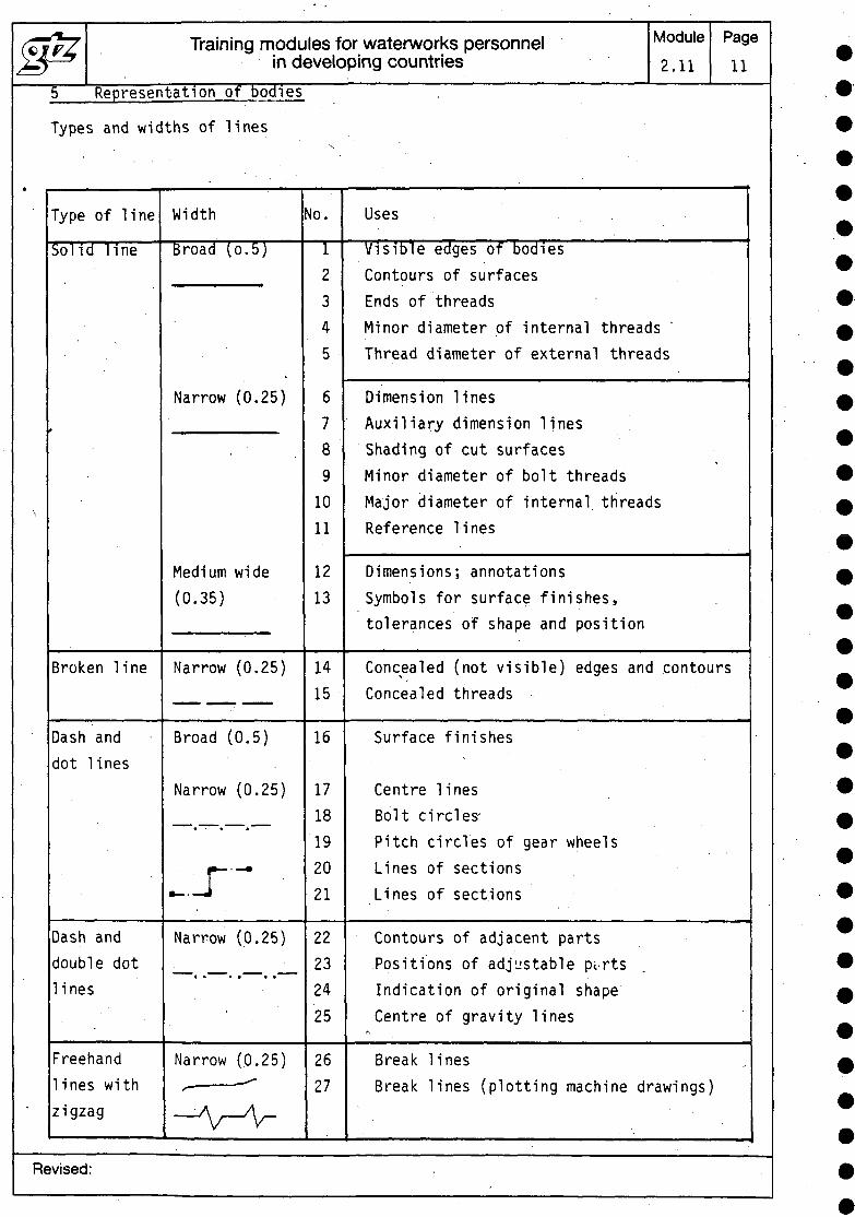
5 Representation of bodies
Types and widths of lines
Type of line
Solid line
Broken line
Dash anddot lines
Dash anddouble dotlines
Freehandlines withzigzag
Width
Broad (o.5)
Narrow (0.25)
Medium wide(0.35)
Narrow (0.25)
Broad (0.5.)
Narrow (0.25)
» ^ ~* * ^ ~*
_-r~Narrow (0.25)
• » ^ » • " ~~ • •
Narrow (0.25)/•' '
\
No.
12345
67891011
1213
1415
16
1718192021
22232425
2627
Uses . . .
Visible edges of bodiesContours of surfacesEnds of threadsMinor diameter of internal threadsThread diameter of external threads
Dimension linesAuxiliary dimension linesShading of cut surfacesMinor diameter of bolt threadsMajor diameter of internal threadsReference Tines
Dimensions; annotationsSymbols for surface finishes,tolerances of shape and position
Concealed (not visible) edges and contoursConcealed threads
Surface finishes
Centre linesBolt circles-Pitch circles of gear wheelsLines of sectionsLines of sections
Contours of adjacent partsPositions of adjustable pi rtsIndication of original shapeCentre of gravity lines
Break linesBreak lines (plotting machine drawings)
Revised:

Training modules for waterworks personnelin developing countries
Module
2.11
Page
12
5.1 Stereoscopic representation of perspective
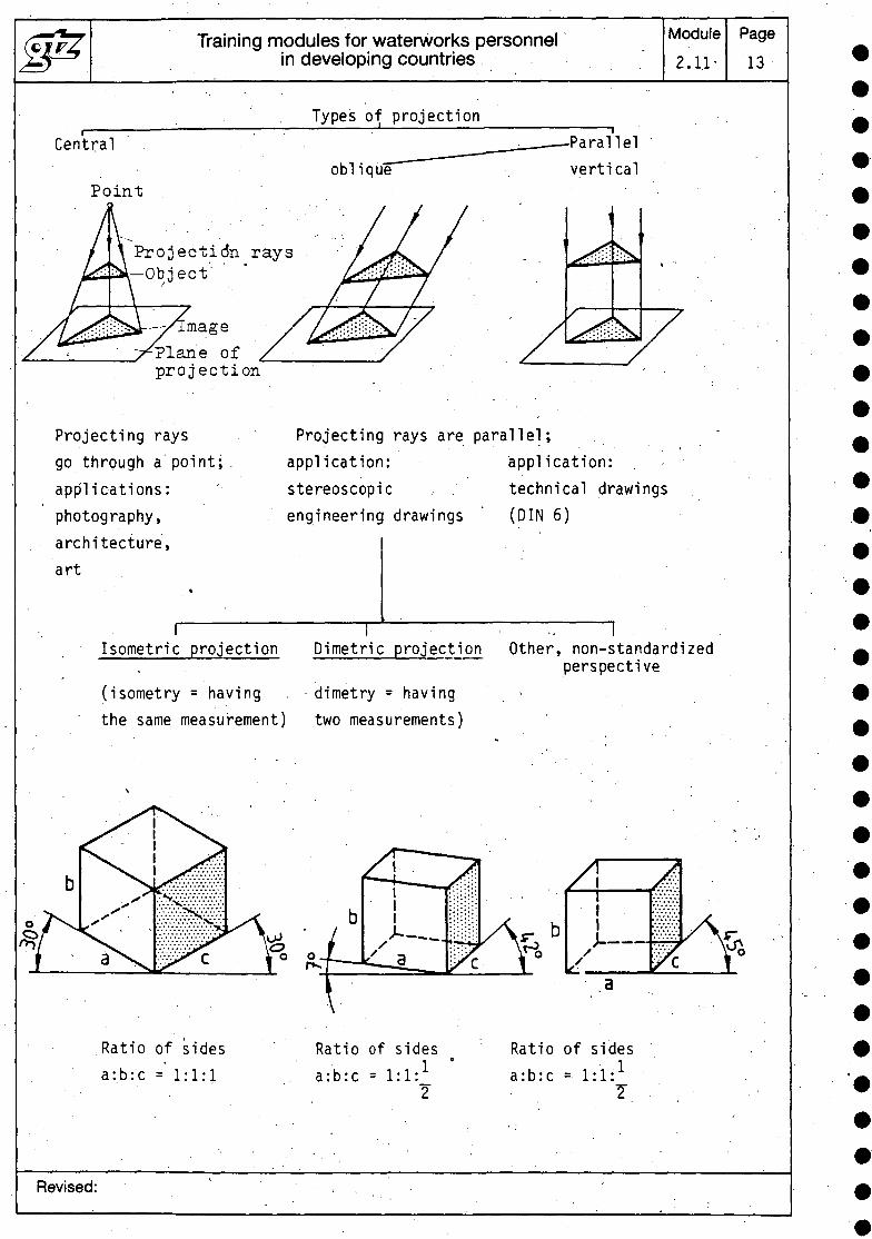
What is projection?
In projection, the object is represented on a plane surface(plane of projection) by means of projecting rays from alight source.
Revised:
J&Central
Poin
/I i^*£-+5*
Training modules for waterworks personnel Module Pagein developing countries 2.1.1- 13
Types of projection————————————————— -i ———————————————— ,^__________ — .Parallel
oblique verticalt ' • • • • ' . -
Projection rays /x«fNv / - ^^i^w u J U U I/ ^CZ^if1**^^^]
^-/fmage / /^^^J/ / >^ ./T^Plane of / / / /
projection - •
Projecting rays Projecting rays are parallel;go through a point; . application: application: . -applications: ' stereoscopic . technical drawingsphotography, engineering drawings (DIN 6)architecture,art
. 1 - . . • . . - .Isometric projection Dimetric projection Other, non-standardized
(iscthe
\
J<
perspectivemetry = having . dimetry = havingsame measurement) two measurements)
Tx. ' • ' • ' •-,^^^ £-+-—s^ /I As* •.s^xv.v'.-Xv.- J ;:;:;:;: . - • I •:•:•:•:•:.;
•i.x-XvX-XvX^j \^ • 1 )-. •••••:-: /\f b ! ••'•;':'::: /\f^^Pc p fJ la_ j^ Y° / pT r
Ratio of sides Ratio of sides t Ratio of sides.a:b:c =' 1:1:1 a:b:c = l:l:1 a :b:c = I:!:1
' . 2 , 1 '
Revised: ,
"otparallel , ^
th
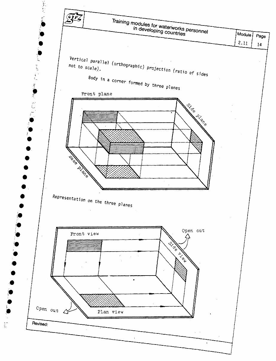
Front plane
tt
of 1(S7des
p,anes
[Module/ Page
2.11 / 14
Open out
Open
Revised:
out
Training modules for waterworks personnelin developing countries
Module
2.11
Page
15
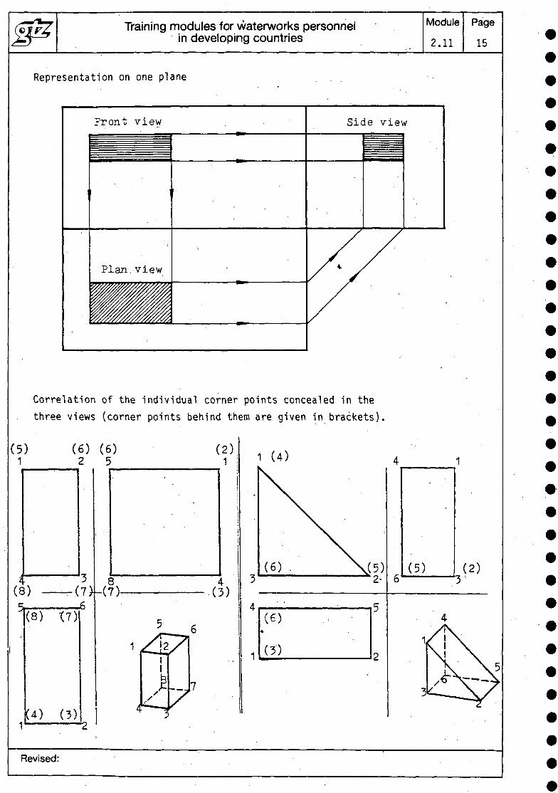
Representation on one plane
Front view Side view
Plan.view
Correlation of the individual corner points concealed in thethree views (corner points behind them are given in brackets).
(5)1
(6) (6)2 5
(8)
1
(8) X7)
(4) (3)
(7>U7)-
(2)1
4(3)
1 (4)
COi
(3)
(5) (2)
Revised:

Training modules for waterworks personnelin developing countries
Module
2.11
Page
16
Exercises:
(7)
(5)
5.2 Rules for the representation of cross-sectionsConcept:
A cross-se'ction is the plane figure produced by a cut througha solid body. The aim is to simplify representation anddimensioning of the drawn part and to facilitate compre-hension.
The imaginary cut is usually through the centre of the body.
When a cross-section is drawn, edges which were concealedbefore become visible. Concealed edges of the body are notrepresented.Types of cross-section:1. Full section2. Half section3. Part section
Revised:
Training modules for waterworks personnelin developing countries
Module
2.11Page
17
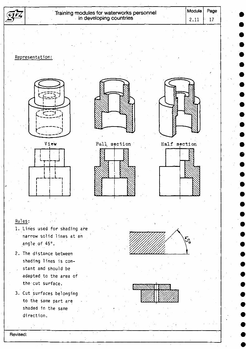
Representation:
View
L,.-L-II.
_L_
Pull, section Half section
Rules: •1. Lines used for shading are
narrow solid lines at. an .angle.of 45°.
2. The distance betweenshading lines is con-
, stant and should beadapted to the area ofthe cut surface.
3. Cut surfaces belongingto the same part areshaded in the same :direction.
Revised:
Training modules for waterworks personnelin developing countries
Module
2.11
Page
18
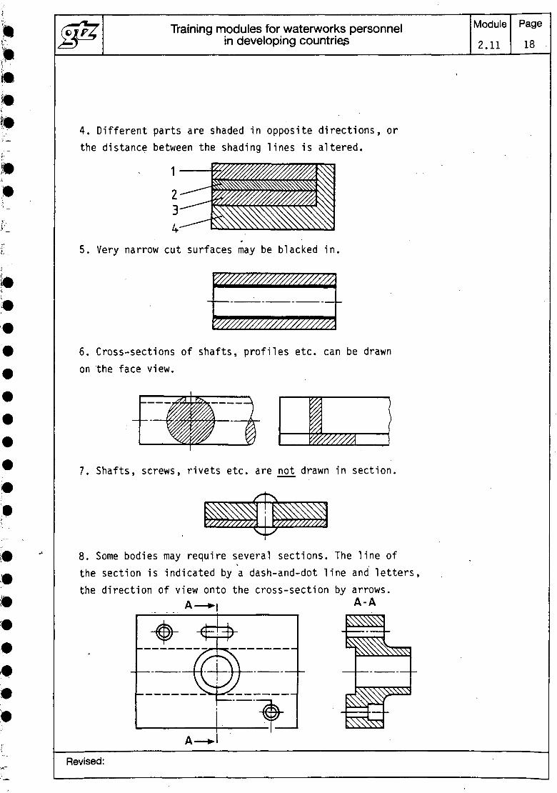
4. Different parts are shaded in opposite directions, orthe distance between the shading lines is altered.
1
5. Very narrow cut surfaces may be blacked in.
6. Cross-sections of shafts, profiles etc. can be drawnon the face view.
IW/////A
7. Shafts, screws, rivets etc. are not drawn in section.
8. Some bodies may require several sections. The line ofthe section is indicated by a dash-and-dot line and letters,the direction of view onto the cross-section by arrows.
A — A-A
Revised:
Training modules for waterworks personnelin developing countries
Module
2.11
Page
19
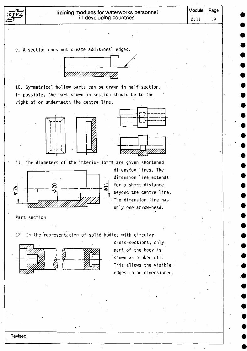
9. A section does not create additional edges.
'////////////////////STfl,
10. Symmetrical 'hollow parts can be drawn in half section.If-possible, the part shown in section should be to theright of or underneath the centre line.
\11. The diameters of the interior forms are given shortened
dimension lines. Thedimension line extendsfor a short distancebeyond the centre line.The dimension line hasonly one arrow-head.
Part section
oO-Je
'///////////////////. WM
-±~-e-
12. In the representation of solid bodies with circularcross-sections, onlypart of the body isshown as broken off.This allows the visibleedges to be dimensioned.
Revised:

Training modules for waterworks personnelin developing countries
Module2.11
Page20
Break lines
13. Objects can be drawn broken off. The break line ofcylindrical bodies is shown by curved free-hand lines.
5.3 Rules for the dimensioning of drawings
1. The dimensions in technical drawings give informationon aspects of the manufacture of a part, its functioningand test results.
Dimension lines
2. Dimension lines are narrow solid Lines.3. The first dimension line must be at least 8 mm away fromthe edge of the body; following this, the distance betweendimension lines is at least 5 mm.4. The dimension figure is written above - or where spaceis limited,, next to - the dimension line.
12
1,8
2,5
5. Edges of bodies and centre lines may not be used asdimension lines.6. Equally, dimension lines must not be drawn as extensionsof edges of bodies or centre lines.7. The dimension lines indicating the length of an arc orthe size of an angle are drawn as follows:
Revised:

Training modules for waterworks personnelin developing countries
Module2.11
Page21
Auxiliary dimension lines
8. Auxiliary dimension lines are narrow solid lines.9. Auxiliary dimension lines generally begin at the edgeof the body and at right angles to it. . , '10. Auxiliary dimension lines extend for 1 to 2 mm beyondthe dimension line.1.1. Wherever possible, auxiliarydimension lines should not crosseach other or any other line.12. Centre lines may be used asauxiliary dimension lines.Outside the edges of the body,these are then continued asnarrow solid lines.13. Auxiliary dimension lines must not be continued fromone view through to another.
Dimension arrows ,
14. The length of the arrow isequal to roughly five timesthe width of the lines usedfor the edges of the body.15. Where space is limited,the arrows are drawn on the ,outside, or points are used.16. Dimension lines for radii or shortened diameter dimensionlines have only one arrow-head.
Dimensions
17. The units of the dimensions are not named. Any unitswhich deviate from the others' must be given.18. The size of the lettering depends on that of the drawing;3.5 mm is normal.
Revised:
training modules for waterworks personnelin developing countries
Module
2.11Page22
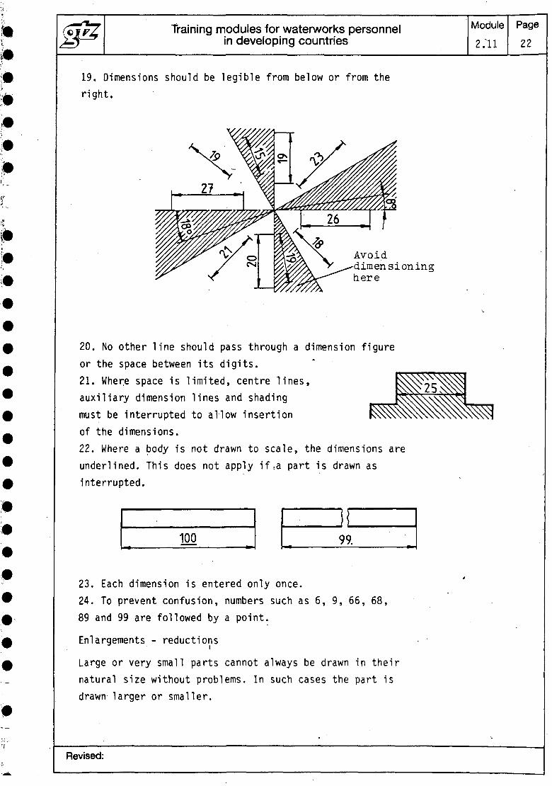
19. Dimensions should be legible from below or from theright.
Avoiddimensioninghere
20. No other line should pass through a dimension figureor the space between its digits.21. Where space is limited, centre lines,auxiliary dimension lines and shadingmust be interrupted to allow insertionof the dimensions.22. Where a body is not drawn to scale, the dimensions areunderlined. This does not apply if ,a part is drawn asinterrupted.
100 99.
23. Each dimension is entered only once.24. To prevent confusion, numbers such as 6, 9, 66, 68,89 and 99 are followed by a point.
Enlargements - reductions
Large or very small parts cannot always be drawn in theirnatural size without problems. In such cases the part isdrawn larger or smaller.
Revised:

Training modules for waterworks personnelin developing countries
Module
2.11
Page
23
In addition to the natural scale (1 :specifies the following scales:
Enlargements:2 : 1 5 : 1 1 0 : 1Reductions:1 : 2 1 : 5 11 : 20 1 : 50 11 : 200 1 : 500 1
1), DIN ISO 5455
101001000
When dimensioning the drawing,.it is always the actualdimensions of the part which are entered. In the title ofthe drawing, the main scale is given in large letteringand the other scales in small lettering. Where the scalediffers from the main scale, this is indicated next to therelevant part. . .
70
5 thick
20 1560
oCSI
iStht'ck
01;
i •; 1 : 260
Diameter
1. The height of the diameter sign is equal to that ofthe dimension figure.
Line at an angle of 75°—————•—- passes through the centre
of the circle
Circle the same sizeas small letters
Revised:
Training modules for waterworks personnelin developing countries
Module2.11
Page24
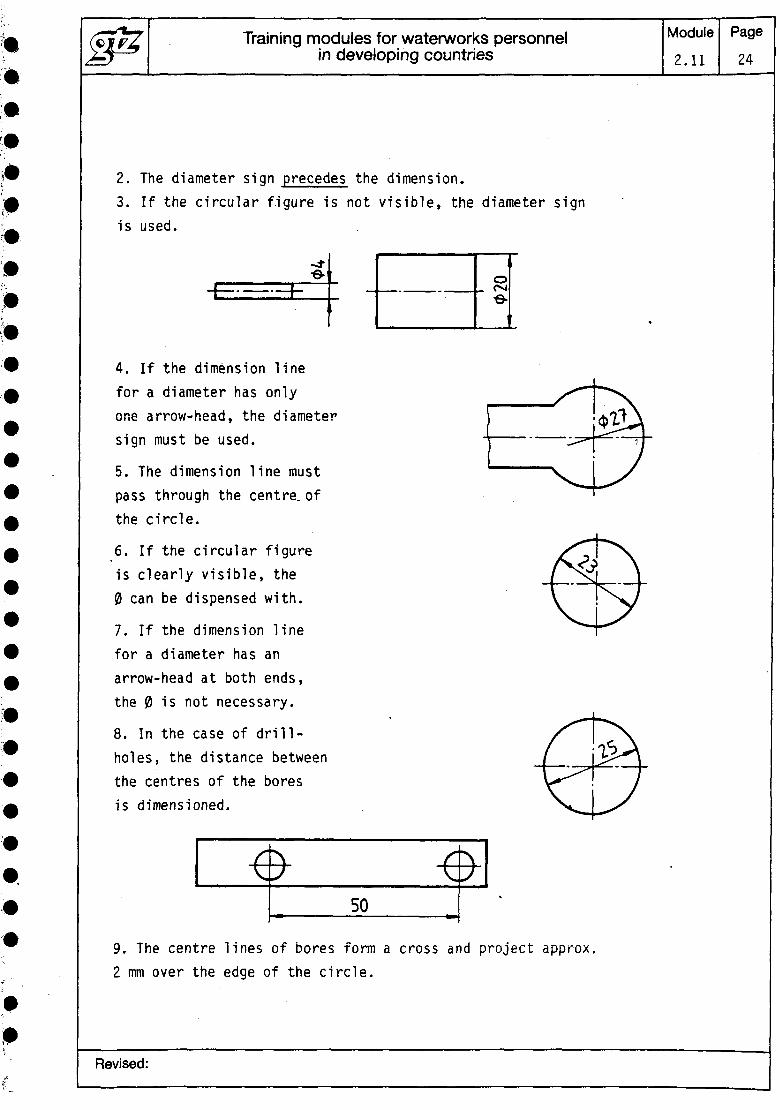
2. The diameter sign precedes the dimension.3. If the circular figure is not visible, the diameter signis used.
4. If the dimension linefor a diameter has onlyone arrow-head, the diametersign must be used.
5. The dimension line mustpass through the centre, ofthe circle.
6. If the circular figureis clearly visible, the0 can be dispensed with.
7. If the dimension linefor a diameter has anarrow-head at both ends,the 0 is not necessary.
8. In the case of drill-holes, the distance betweenthe centres of the boresis dimensioned.
o«•
50
9. The centre lines of bores form a cross and project approx.2 mm over the edge of the circle.
Revised:
Training modules for waterworks personnelin developing countries
Module2.11
Page25
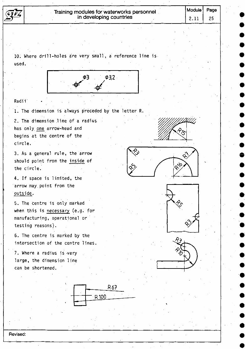
10. Where drill-holes are very small, a reference line isused.
03,2
Radii • (
1. The dimension is always preceded by the letter R
2. The dimension line of a radius,has only one arrow-head andbegins at the centre of thecircle.
3. As a general rule, the arrowshould point from the inside ofthe circle.
4. If space is limited, thearrow may point from theoutside.
5. The centre is only markedwhen this is necessary (e.g. formanufacturing, operational ortesting reasons).
6. The centre is marked by theintersection of the centre Tines.
7. Where a radius is-verylarge, the dimension linecan be shortened.
Revised:
Training modules for waterworks personnelin developing countries
Module2.11
Page26
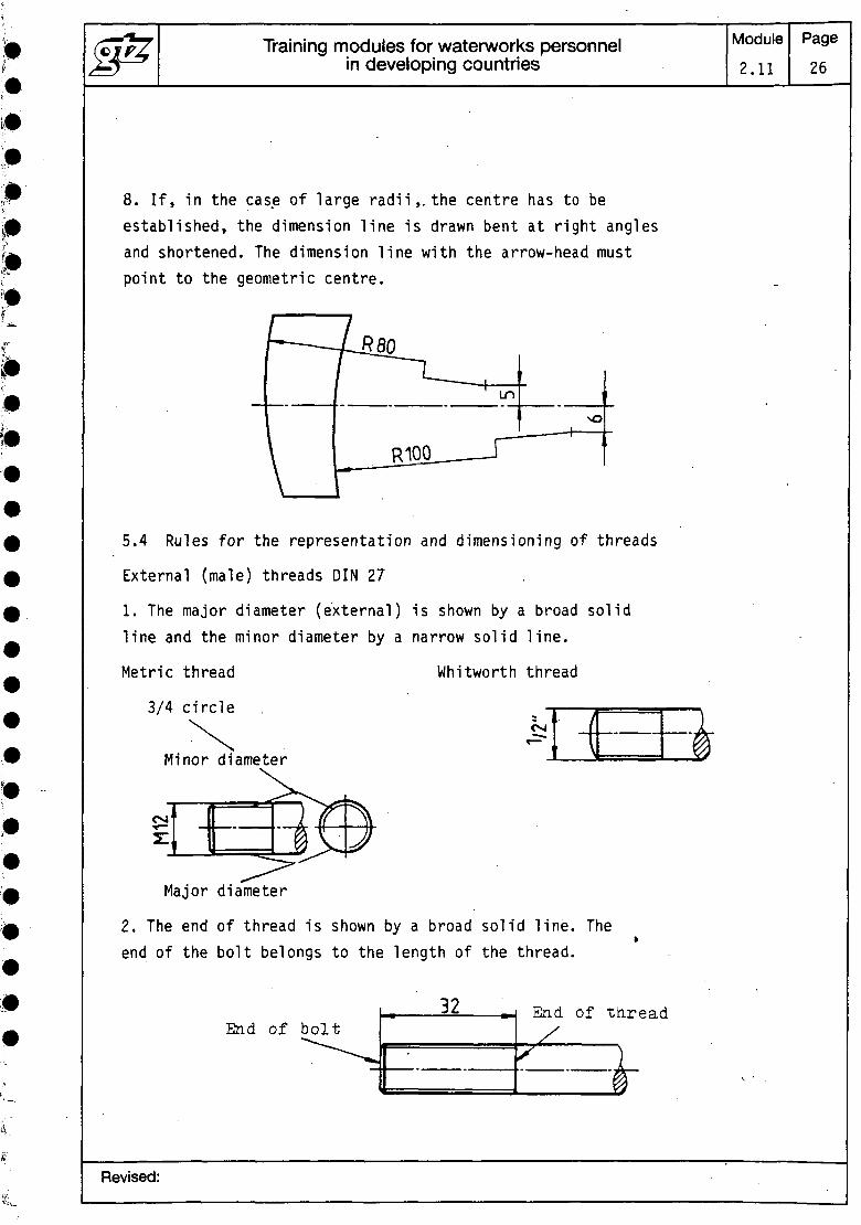
8. If, in the case of large radii,, the centre has to beestablished, the dimension line is drawn bent at right anglesand shortened. The dimension line with the arrow-head mustpoint to the geometric centre.
5.4 Rules for the representation and dimensioning of threads
External (male) threads DIN 27
1. The major diameter (external) is shown by a broad solidline and the minor diameter by a narrow solid line.
Metric thread Whitworth thread
3/4 circle
Minor diameter
CVI
Major diameter
2. The end of thread is shown by a broad solid line. Theend of the bolt belongs to the length of the thread.
End of bolt ^- -H End of th
s }
Revised:

Training modules for waterworks personnelin developing countries
Module2.11
Page27
3. The major diameter is dimensioned and given the appro-priate designation according to DIN 202, e.g.:M 12 • Metric thread, 0 - in mmM 20 x 1.5 Metric fine thread, 0 in mm
(•
1/2" Whitworth thread, 0 in inchesW 84 x 1/6" Whitworth fine thread, 0 in mm, pitch in inches
; • •Internal (female) threads
4. The minor diameter is.shown by a broad solid line andthe major diameter by a narrow solid line.
The shading is continued up to the broad solid line.
M12-LH
Left-handed thread (-LH)
M16 x 1,5
Right-handed thread (-RH)
5. For a tapped blind hole, the minor diameter must firstbe drilled and then the thread cut.
Revised:

Training modules for waterworks personnelin developing countries
Module
2.11
Page
28
6. A thread can also be drawn concealed.
Tapped blind hole, front and side view
s;-
7. Simplified representation of small internal threads.
Nominal diameter = 5 mmM3
M5
M3-LH
Screwed connections
8. In the representation of screwed connections, the screwsand nuts are not drawn.
Drawing of screw Internal threads areonly shown where theyare not concealed bythe bolt thread.
Revised:
Training modules for waterworks personnelin developing countries
Module2.11
Page29
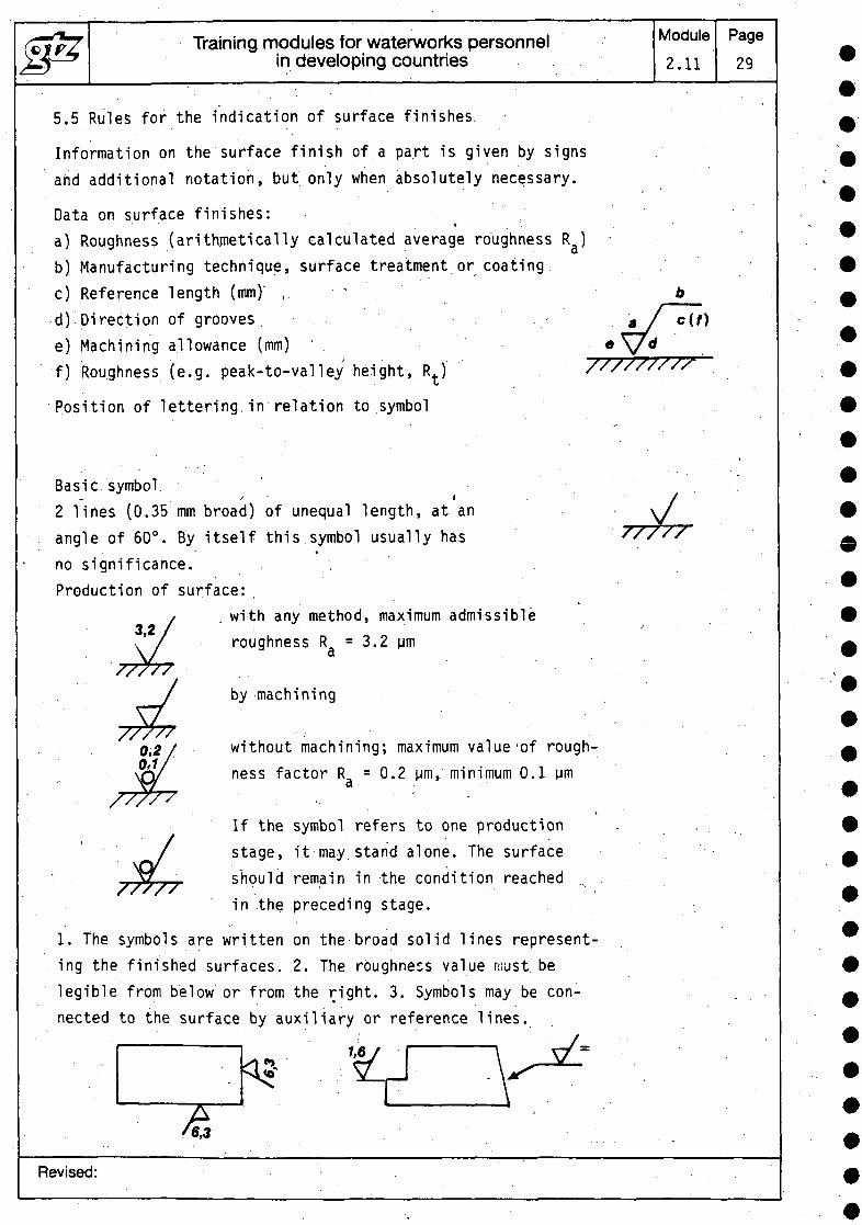
5.5 Rules for the indication of surface finishes.
Information on the surface finish of a part is given by signsand additional notation, but only when absolutely necessary.
Data on surface finishes:*
a) Roughness (arithmetically calculated average roughness R^)b) Manufacturing technique, surface treatment or coating.c) Reference length (mm)' , vd) Direction of grooves, . ,e) Machining allowance (mm)f) Roughness (e.g. peak-to-valley height, R^)
Position of lettering.in relation to symbol
Basic symbols I
2 lines (0.35 mm broad) of unequal length, at anangle of 60°. By itself this symbol usually hasno significance. . , .Production of surface:
i with any method, maximum admissibleroughness R, = 3.2 urna
by machining
without machining; maximum value'of rough-ness factor R, = 0.2 Mm, minimum 0.1 urna
If the symbol refers to one productionstage, it may.stand alone. The surfaceshould remain in the condition reachedin the preceding stage. . .
1. The symbols are written on the broad solid lines represent-ing the finished surfaces. 2. The roughness value must belegible from below or from the right. 3. Symbols may be con-nected to the surface by auxiliary or reference lines.
/&3
Revised:
Training modules for waterworks personnelin dsveloping countries
Module
2.11
Page
30
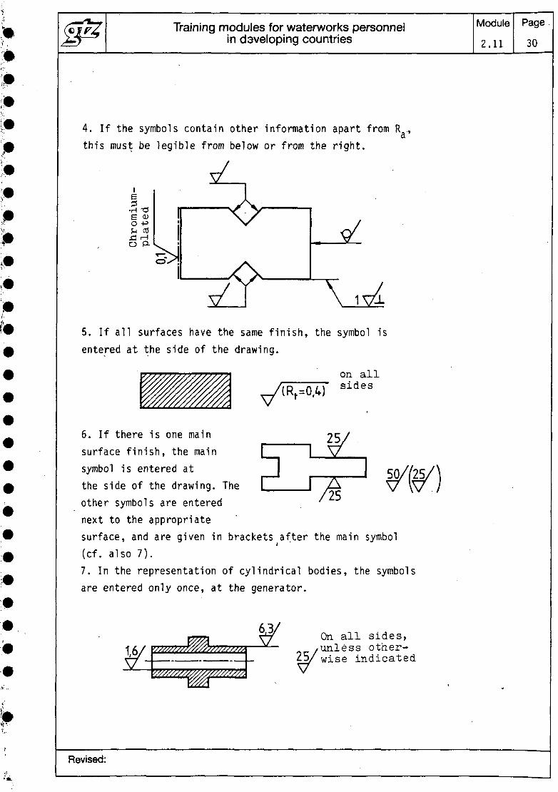
4. If the symbols contain other information apart from R ,a
this must be legible from below or from the right.
O
5. If all surfaces have the same finish, the symbol isentered at the side of the drawing.
on allsides
6. If there is one mainsurface finish, the mainsymbol is entered atthe side of the drawing. Theother symbols are enterednext to the appropriatesurface, and are given in brackets after the main symbol(cf. also 7).7. In the representation of cylindrical bodies, the symbolsare entered only once, at the generator.
'////////////////////S///
W//////V///7/////7/7/J r
On all sides,unless other-wise indicated
Revised:
Training modules for waterworks personnelin developing countries
Module2.11
Page31
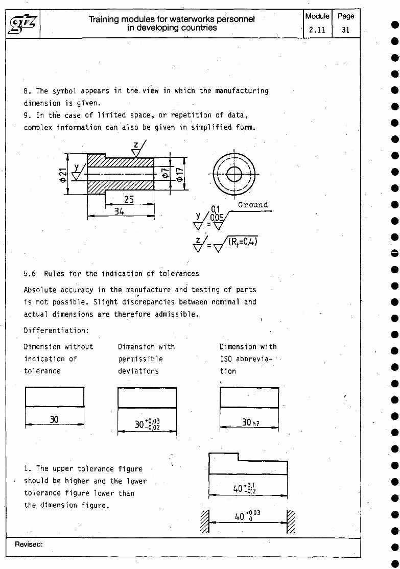
8. The symbol appears in the. view in which the manufacturingdimension is given.9. In the case of limited space, or repetition of data,complex information can also be given in simplified form.
Csl•©.?ffl////////////\y_
2534
r*-
5.6 Rules for the indication of tolerances
Absolute accuracy in the manufacture and testing of partstis not possible. Slight discrepancies between nominal andactual dimensions are therefore admissible.
Differentiation:
Dimension withoutindication oftolerance
30
Dimension withpermissibledeviations
.-0.02
Dimension withISO abbrevia-tion
30
1. The upper tolerance figureshould be higher and the lowertolerance figure lower thanthe dimension figure.
/n*0-40 -0-0;2
40
Revised:
Training modules for waterworks personnelin developing countries
Module2.11
Page32
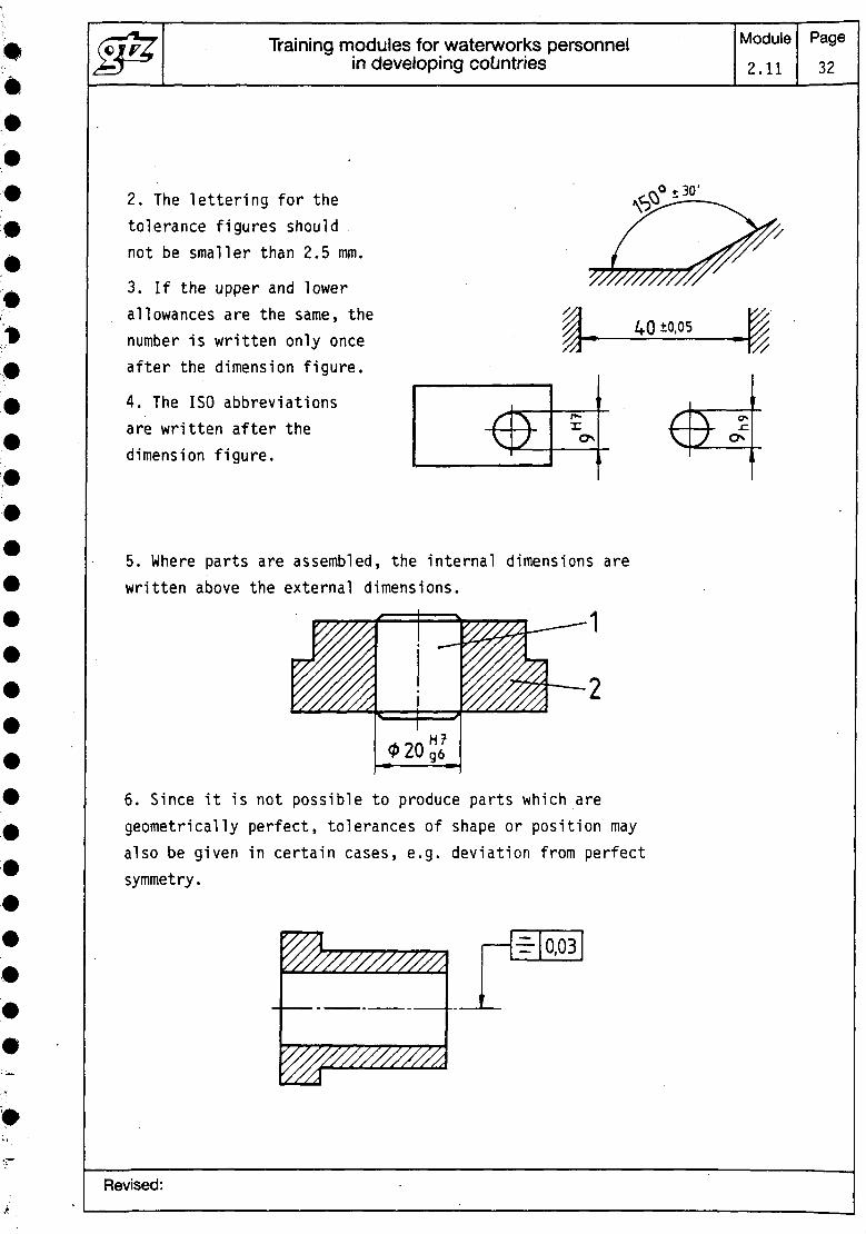
2. The lettering for thetolerance figures shouldnot be smaller than 2.5 mm.
3. If the upper and lowerallowances are the same, thenumber is written only onceafter the dimension figure.
4. The ISO abbreviationsare written after thedimension figure.
5. Where parts are assembled, the internal dimensions arewritten above the external dimensions.
6. Since it is not possible to produce parts which aregeometrically perfect, tolerances of shape or position mayalso be given in certain cases, e.g. deviation from perfectsymmetry.
Y///////7//7//ZA/ / / /\ . 1 1 1 1 1 « 1 1 1 1
Revised:

JS
6
Training modules for waterworks personnelin developing countries
e-
Representation of pipelines and other componentsof water-supply systems
Module Page
2.11 33
Pictograms ' .
Pictograms are highly schematized depictions of pipes, .valves and other parts in pipe lay-out and control plans. :
The pictograms can be shown in any position, correspondingto the direction taken by the pipes.
6.1 Pipes
1.
2.
3.
4.
Basic main(basic pictogram)
Control pulse main
Differential press-ure main
Extension main *
5. Mobile main
6.2
1.
3.
5.
7.
9 . -
— . — . —
0 -
6.
7.
8.
9.
10.
Jacketed main
Heater
Intersection oftwo mains with-out joint
Intersection oftwo mains withjoint
Branch
T T,
AV
I
Joints ' • • . . '
Pipe joint'basic pictogram)
:lange joint withblind hole ring
Socket joint
Slide-on socketjoint
Screwed joint
-tj--N
-^
-f-
2.
4.
6.
8.
10.
Flange joint
Blind flange
Ball '.socket joint
Clamp (supported)joint
Coupling
-
,(-x
^i — i
•— i± —TI-LL
Revised:

J^ Training modules for waterworks personnelin developing countries
11.
13.
15.
Welded or solderedjoint
Welded ball socketjoint
Welded-in valve
~^-
-Cx>-
12.
14.
Welded socketjoint
Welded slide-insocket joint
Module
,2.11
^V
— f
6.3 Valves
1.
3.
5.
7.
9.
11.
13.
15.
17.
Stop valve(basic pictogram)
Stop valve open
Stop valve withhand crank
with piston drive-
with motor drive
with float control
Gate valve
Spring-loadedsafety gate valve
Non-return valve,not closeable
1X1
i fc i^x^xj
tx]
&&^XI
CX3
la
2.
4.
6.
8.
10.
12.
14.
16.
18.
Stop valveclosed
Stop valve withhand wheel
Power-drivenstop valve
with magneto drive
with diaphragmcontrol
Control valve(basic pictogram)
Weight-loadedsafety gate valve
Non-return gatevalve, closeable
Foot valve
HXH-
OKI
X]
Sffi
XI
t*3
M
As
Page
34
Revised:
(£fp7 Training modules for waterworks personnelj^y— in developing countries
e
e-
•
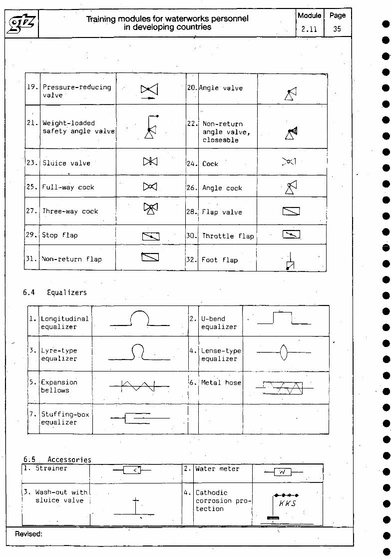
19.
21.
23.
25.
27.
29.
31.
Pressure-reducingvalve
Weight-loadedsafety angle valve
Sluice valve
Full-way cock
Three-way cock
Stop flap
Non-return flap
.KI
£wwL " ^«j
^ j ^^
sts
5.4 Equalizers
1.
3.
5.
7.
Longitudinalequalizer
Lyre-typeequalizer
Expansionbellows
Stuffing-boxequalizer
20.
22.
24.
26.
28.
30.
32.
-^V_ .
0\y\ /\
\/" \
5.5 , AccessoriesL. Strainer
5. Wash-out withsluice valve
Angle valve
Non-returnangle valve,closeable
Cock
Angle cock
Flap valve
Throttle flap
Foot flap
Module
2.11
£i*XI
•^csE],
^ \
2.
4.
6.
-03- :
. . ' T »
L
> _
;.
Revised:
U-bendequalizer
Lense-typeequalizer
Metal hose
A.
^.-
\ • / A.' V \
.
Water meter r—, — \
Cathodiccorrosion pro-tection
KKSt-
Page
35
\
Training modules for waterworks personnelin developing countries
Module
2.11
Page
36
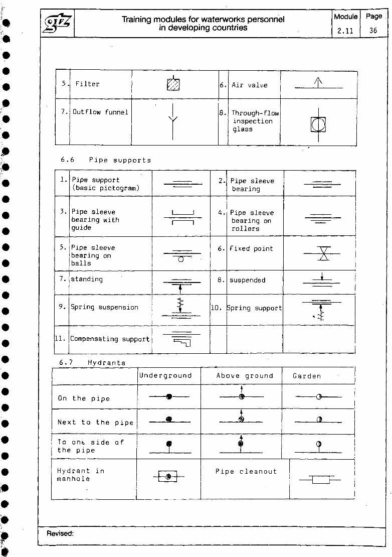
5.
7.
Filter
Outflow funnel\s
6.
8.
Air valve
Through- flowinspectionglass
'!
(
\
~\
6 .6 Pipe support s
1.
3.
5.
7.
9.
11.
Pipe support(basic pictogram)
Pipe sleevebearing withguide
Pipe sleevebearing onballs——————————————standing
'Spring suspension
———————————————
Compensating support
, ,
' '
~1
jL. ———— .
————
=n
2.
4.
6.
8.
10.
Pipe sleevebearing
Pipe sleevebearing onrollers
Fixed point
suspended
Spring support
|
|
^
i
T
6 . 7 Hydrants
On the pipe
Next to the pipe
To ont. side ofthe pipe
Hydrant inmanhole
Underground
9
t"1
Above ground
t
<?), tt>
Pipe cleanout
Garden
0
n>
ICO
•1i
' _____ 1 | ____ !
Revised:
(c7?Z Training modules for waterworks personnel Module Page^Jy—^ • in developing countries 2.11 37
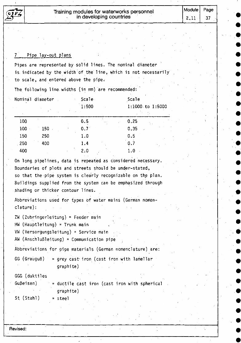
7 Pipe lay-out plans
-
Pipes are represented by solid lines. The nominal diameteris. indicated by the width of the line,to scale, and entered above the pipe.
The following line, widths (in mm) are
Nominal diameter . Scale, 1:500
100 0.5100 150 . 0.7150 250 1.0
.250 400 1.4400 2.0
On long pipelines, data is repeated asBoundaries of plots and streets should
which is not necessarily
recommended: ;
Scale1:1000 to 1:5000
0.250.350.50.7 .1.0
considered necessary.be under-stated,
so that theipipe system is clearly recognizable on the plan.Buildings supplied from the system can.shading or thicker contour lines.
Abbreviations used for types of waterclature) :
ZW (Zubringerleitung) = Feeder mainHW (Hauptleitung) = Trunk mainVW (Versorgungsleitung) = Service main
be emphasized through•
mains (German nomen-
. • •
AW (AnschluBleitung) = Communication pipe
Abbreviations for pipe materials (German nomenclature) are:
GG (GrauguR) = grey cast iron (castgraphite)
GGG (duktiles
iron with lamellar
Gu&eisen) = ductile cast iron (cast iron with spherical . . .• • graphite)
St (Stahl) = steel ..
Revised: . .

Training modules for waterworks personnelin developing countries
Module2.11
Page38
AZ (Asbestzement)Sb (Stahlbeton)Spb (Spannbeton)PEh (Polyathylen hart)PEw (Polyathylen weich)PVC (Polyvinylchlorid)
= asbestos cement= reinforced concrete= prestressed concrete= high-density polyethylene= low-density polyethylene= polyvinyl chloride
If protective coatings are named, the following abbreviationsare used in German:
External protection:
Ba (bituminbse Umhullung)dBa (doppelte bituminb'se Umhlillung)
- bituminous coating= double bituminous
coating= plastics coating
= bituminous lining= cement mortar lining= plastics lining
Ka (Kunststoffumhiillung)
Internal protection:
Bi (bituminbse Auskleidung)Zm (Zementmbrtelauskleidung)Ki (Kunststoffauskleidung)
The following abbreviations are used in German for thecommonest types of pipe joints:
No letters addedSr (Schraub-Muffen-Verbindung)'Sm (Steck-Muffen-Verbindung)Sw (SchweiB-Verbindung)Grr (Gummi-Rollring-Verbindung) = rubber 0-ring jointStb, (Stopfbuchs-Verbindung) = stuffing-box jointKl (Klebemuffe) = cemented socket jointKm (Klemm-Verbindung) = supported jointFl (Flansch-Verbindung) = flange joint
Transitions from one material or one diameter to another,or between two types of joint, are shown as follows:
= calked socket joint= screwed socket joint= slide-in socket joint= welded joint
GG St 100 200 Sm Sr
Revised:

Training modules for waterworks personnelin developing countries
Module2.11
Page39
Indications of the level of a water main apply optionallyeither to the upper or to the lower pipe edge in relationto m.s.l. Only one of the two options may normally be usedon the same plan. If there is some reason for not observingthis rule, the deviation must be clearly indicated.
The heights are written at right angles to the pipe andunderlined.. The line indicates the point in the lay-outplan to which the height refers.
The thickness of the soil covering over pipes is given inmetres, without "m", in brackets above the line representingthe pipe.
Where pipes intersect, the pipe which is uppermost is repre-sented by a continuous line. ———j———
Any other pipes which do not belong to the pipe system areshown by a broken line: _ _ _ _
The pressures .in water mains are, if required, noted abovethe drawn main, followed by the unit ("bars").
The following pictograms are also permissible for simplifiedrepresentation of stop valves:
Sluice valve Flap valve K Cock H
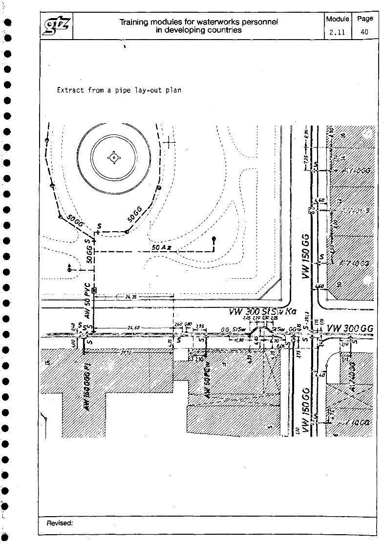
An extract from a pipe lay-out plan is shown on page 40.
Revised:
Training modules for waterworks personnelin developing countries
Module
2.11
Page
40
Extract from a pipe lay-out plan
Revised:
Training modules for waterworks personnel1in developing countries
Module
•2.11
Page41
8 Bibliography
H. Volquardts/K.. Matthews Vermessungskunde 1Teubner Stuttgart -
Sonntag/Kraus Bau-Technologi.eHandwerk u. .Technik
Scholz-GrUhn '--. Grundlehrgang Technisches/ • • • • •Zeichnen Metal.lGehlen Bad Homburg
The illustrations in section 5 were taken from thiscourse. . '
DIN standardsDIN 2425 . . .DIN 2429
Some passages of text were taken unaltered from thepublications named above. . .\ . .
Revised:

Deutsche Gesellschaftfur Technische Zusammenarbeit (GTZ) GmbHDag-Hamrrtarsk/old-V^g 1 * 2 D 6236 Eschbom 1 Te/efbn (061961 79-O Telex 407501-Ogtzd
The government-owned GTZ operates in the field of TechnicalCooperation. Some 4,500 German experts are working together withpartners from some 100 countries in Africa, Asia and Latin America inprojects covering practically every sector of agriculture, forestry, economicdevelopment, social services and institutional and physical infrastructure.- The GTZ is commissioned to do this work by the Government of theFederal Republic of Germany and by other national and internationalorganizations.
GTZ activities encompass:
- appraisal, technical planning, control and supervision of technicalcooperation projects commissioned by the Government of the FederalRepublic of Germany or by other authorities
- advisory services to other agencies implementing developmentprojects
- the recruitment selection, briefing and assignment of expert personneland assuring their welfare and technical backstopping during theirperiod of assignment
- provision of materials and equipment for projects, planning work,selection, purchasing and shipment to the developing countries
- management of all financial obligations to the partnercountry.
The series "Sonderpublikationen der GTZ" includes more than 190publications. A list detailing the subjects covered can be obtained from theGTZ-Unit 02: Press and Public Relations, or from the TZ-Veriagsgesell-schaft mbH, Postfach 36, D 6101 RoBdorf 1, Federal Republic of Germany.
TRAINING MODULESFOR WATERWORKS PERSONNEL
List of training modules:Basic Knowledge
0.1 Basic and applied arithmetic0.2 Basic concepts of physics0.3 Basic concepts of water chemistry0.4 Basic principles of water transport1.1 The function and technical composition of
a watersupply system1.2 Organisation and administration of
waterworks
Special Knowledge
2.1 Engineering, building and auxiliarymaterials
2.2 Hygienic standards of drinking water2.3a Maintenance and repair of diesel engines
and petrol engines2.3b Maintenance and repair of electric motors2.3c Maintenance and repair of simple driven
systems2.3d Design, functioning, operation, mainte-
nance and repair of power transmissionmechanisms
2.3e Maintenance and repair of pumps2.3f Maintenance and repair of blowers and
compressors2.3g Design, functioning, operation, mainte-
nance and repair of pipe fitt ings2.3h Design, functioning, operation, mainte-
nance and repair of hoisting gear2.3i Maintenance and repair of electrical motor
controls and protective equipment2.4 Process control and instrumentation2.5 Principal components of water-treatment
systems (definition and description)2.6 Pipe laying procedures and testing of
water mains2.7 General operation of water mam systems2.8 Construction of water supply units2.9 Maintenance of water supply units
Principles and general procedures2.10 Industrial safety and accident prevention2.11 Simple surveying and technical drawing
Special Skills
3.1 Basic skills in workshop technology3.2 Performance of simple water analysis3.3a Design and working principles of diesel
engines and petrol engines3.3 b Design and working principles of electric
motors3.3 c -3.3d Design and working principle of power
transmission mechanisms3.3e Installation, operation, maintenance and
repair of pumps3.3f Handling, maintenance and repair of
blowers and compressors3.3g Handling, maintenance and repair of
pipe fittings3.3h Handling, maintenance and repair of
hoisting gear3.3i Servicing and maintaining electrical
equipment3.4 Servicing and maintaining process
controls and instrumentation3.5 Water-treatment systems: construction
and operation of principal components:Part I - Part II
3.6 Pipe-laying procedures and testing ofwater mams
3.7 Inspection, maintenance and repair ofwater mains
3.8a Construction in concrete and masonry3.8 b Installation of appurtenances3.9 Maintenance of water supply units
Inspection and action guide3.10 -3.11 Simple surveying and drawing work
Deutsche Gesellschaft furTechnische Zusammenarbeit
(GTZ) GmbH
P 0 Box 5180Dag-Hammarskjo/d-Weg 1+ 2
D6236Eschborn/Ts 7Telephone (06196) 79-0
Telex 407501-0 gtzdFax A/o, (061'96) 75-7775 f
•
Related Documents

![Lecture 16 & 17 - Genetic Algorithms Fundamentals [Read-Only] · 2017-03-24 · GENETIC ALGORITHM Representation of Solutions: The Chromosome Rules Representation We can represent](https://static.cupdf.com/doc/110x72/5f7ae83c99734051ed317803/lecture-16-17-genetic-algorithms-fundamentals-read-only-2017-03-24-genetic.jpg)