SEIKAKU TECHNICAL GROUP LIMITED JAN.25.2011 A3 A4 A5 NH00149 5:2 NH002311:2 TPA GIG 7.800-15 TOPP PRO_V1.0 0.110KG/1 TPA GIG 7.800-15 NF03537 -RS 11PCS 22 NPD-TO-1012004 PHFUA102-20110100080

Tpa gig 7 800 15 topp pro v1-0
Nov 18, 2014
Manual Paquete de Audio profesional de 800 W, Top PRO
Welcome message from author
This document is posted to help you gain knowledge. Please leave a comment to let me know what you think about it! Share it to your friends and learn new things together.
Transcript
SE
IKA
KU
TE
CH
NIC
AL
GR
OU
PLIM
ITE
D
JAN
.25.2011
A3
A4
A5
NH
00
14
95
:2N
H0
02
311
:2
TP
AG
IG7
.80
0-1
5T
OP
PP
RO
_V
1.0
0.1
10
KG
/1
TP
AG
IG7
.80
0-1
5
NF
03
53
7
-RS
11
PC
S
22
NP
D-T
O-1
01
20
04
PH
FU
A1
02
-20
11
01
00
08
0

PLAY - PAUSEPLAY - PAUSE MAIN OUTMAIN OUTMONITOR OUTMONITOR OUTCOMP.COMP. / LIM.LIM.
POWERPOWER
OUTPUT
CH7-8
CH9-10CH9-10
ON
OFF
PROGRAM (PUSH)
DSPMUTE
FUNCTION
FOOTSWITCH
FX SEND
FX RETURN
Echo Verb++
++
+
00-09 Vocal10-19 Small Room20-29 Large Hall30-39 Echo40-49
60-69 Plate50-59 Flange Verb
70-79 Chorus GTR80-89 Rotary GTR90-99 Tremolo GTR
CLIP
MUTE
AMPLIFIER ASSIGN
12V LAMP
SG/PEAK SG/PEAK SG/PEAK SG/PEAK SG/PEAK SG/PEAK
MIC IN (bal.) MIC IN (bal.) MIC IN (bal.) MIC IN (bal.) MIC IN (bal.) MIC IN (bal.)
PHANTOM
24-Bit FX Processor
MIC/LEFT (bal.)IN
Right
TAPE OUT
TAPE IN
BRIDGEBRIDGE
R
R
L
L
AUX / DFX RET
1010
RL
BAL10
FX toMon
10
FX toMain
PAD LINE IN (bal.)
10
DSP/FXAUX1POST
10
10
MON
2.5KHz
MID0
1212
1515
LOW
80Hz
0
12KHz
HIGH0
1515
PAN
RL
SG/PEAK
10
DSP/FXAUX1POST
10
10
MON
2.5KHz
MID0
1212
1515
LOW
80Hz
0
12KHz
HIGH0
1515
PAN
RL
10
DSP/FXAUX1POST
10
10
MON
2.5KHz
MID0
1212
1515
LOW
80Hz
0
12KHz
HIGH0
1515
PAN
RL
10
DSP/FXAUX1POST
10
10
MON
2.5KHz
MID0
1212
1515
LOW
80Hz
0
12KHz
HIGH0
1515
PAN
RL
10
DSP/FXAUX1POST
10
10
MON
2.5KHz
MID0
1212
1515
LOW
80Hz
0
12KHz
HIGH0
1515
PAN
RL
10
DSP/FXAUX1POST
10
10
MON
2.5KHz
MID0
1212
1515
LOW
80Hz
0
12KHz
HIGH0
1515
PAN
RL
10
DSP/FXAUX1POST
10
10
MON
2.5KHz
MID0
1212
1515
LOW
80Hz
0
12KHz
HIGH0
1515
BAL
RL
PAD LINE IN (bal.) PAD LINE IN (bal.) PAD LINE IN (bal.) PAD LINE IN (bal.) LINE IN (bal.)PAD LINE IN (bal.)
LEVEL LEVEL LEVEL LEVEL LEVEL LEVEL LEVEL LEVEL
CH 1 CH 2 CH 3 CH 4 CH 5 CH 6 CH 7-8
CH 1 CH 2 CH 3 CH 4 CH 5 CH 6 CH 7-8 CH 9-10 MULTI - EFFECTS
ON
OFF
MAIN R
MONITOR
MAIN L
MAIN L+R
TPM 7.800
0
CLIP
MONITOR
30
10
LEVEL
10
63 160 400 1K 2 5K. 6 3K. 16K
0
9
9
15
15
0
9
9
15
15
FEEDBACK LOCATOR
POWER
63 160 400 1K 2.5K 6.3K 16K
MAIN
0
CLIP
L R
LEVEL
10
0
9
9
15
15
0
9
9
15
15
30
10
-
-
FEEDBACK LOCATOR
NF03537-1.0
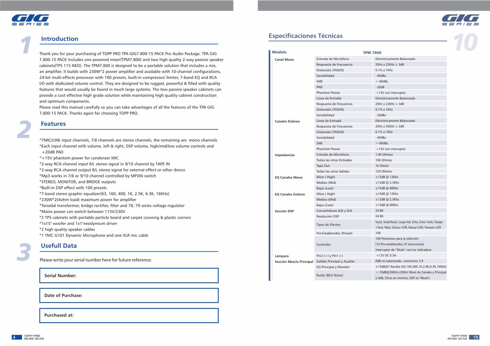
Thank you for your purchasing of TOPP PRO TPA GIG7.800-15 PACK Pro Audio Package. TPA GIG
7.800-15 PACK Includes one powered mixer(TPM7.800) and two high quality 2-way passive speaker
cabinets(TPS 115 NEO). The TPM7.800 is designed to be a portable solution that includes a mix,
an amplifier. It builds with 230W*2 power amplifier and available with 10-channel configurations,
24-bit multi-effects processor with 100 presets, built-in compressor/ limiter, 7-band EQ and RCA
I/O with dedicated volume control. They are designed to be rugged, powerful & filled with quality
features that would usually be found in much large systems. The two passive speaker cabinets can
provide a cost effective high grade solution while maintaining high quality cabinet construction
and optimum components.
Please read this manual carefully so you can take advantages of all the features of the TPA GIG
7.800-15 PACK. Thanks again for choosing TOPP PRO.
*7MIC/LINE input channels, 7/8 channels are stereo channels, the remaining are mono channels
*Each input channel with volume, left & right, DSP volume, high/mid/low volume controls and
+20dB PAD
*+15V phantom power for condenser MIC
*2-way RCA channel input R/L stereo signal in 9/10 channel by TAPE IN
*2-way RCA channel output R/L stereo signal for external effect or other device
*Mp3 works in 7/8 or 9/10 channel controlled by MP3IN switch
*STEREO, MONITOR, and BRIDGE outputs
*Built-in DSP effect with 100 presets
*7-band stereo graphic equalizer(63, 160, 400, 1K, 2.5K, 6.3K, 16KHz)
*230W*2(4ohm load) maximum power for amplifier
*Toroidal transformer, bridge rectifier, filter and 78, 79 series voltage regulator
*Mains power can switch between 115V/230V
*2 TPS cabinets with portable particle board and carpet covering & plastic corners
*1x15" woofer and 1x1"neodymium driver
*2 high quality speaker cables
*1 TMC G101 Dynamic Microphone and one XLR mic cable
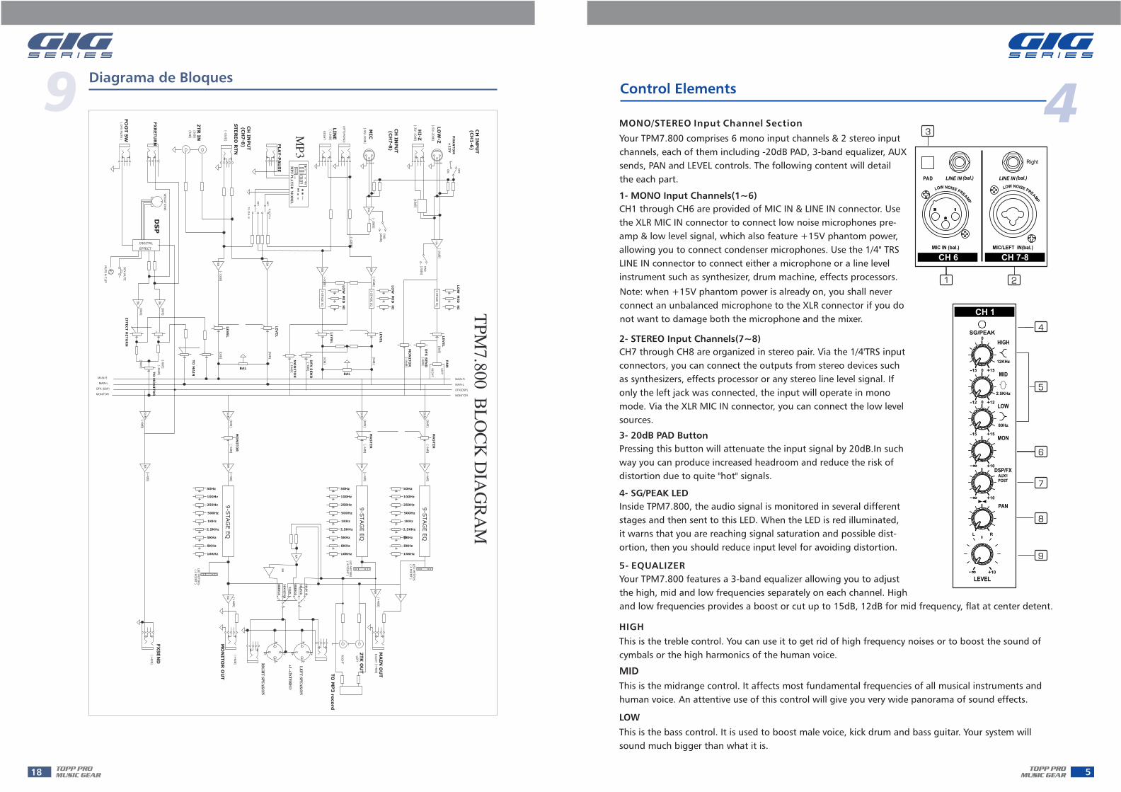
MONO/STEREO Input Channel Section
Your TPM comprises 6 mono input channels & 2 stereo input
channels, each of them including -20dB PAD, 3-band equalizer, AUX
sends, PAN and LEVEL controls. The following content will detail
the each part.
7.800
1- MONO Input Channels(1~6)
CH1 through CH6 are provided of MIC IN & LINE IN connector. Use
the XLR MIC IN connector to connect low noise microphones pre-
amp & low level signal, which also feature +15V phantom power,
allowing you to connect condenser microphones. Use the 1/4" TRS
LINE IN connector to connect either a microphone or a line level
instrument such as synthesizer, drum machine, effects processors.
Note: when +15V phantom power is already on, you shall never
connect an unbalanced microphone to the XLR connector if you do
not want to damage both the microphone and the mixer.
2- STEREO Input Channels(7~8)
CH7 through CH8 are organized in stereo pair. Via the 1/4'TRS input
connectors, you can connect the outputs from stereo devices such
as synthesizers, effects processor or any stereo line level signal. If
only the left jack was connected, the input will operate in mono
mode. Via the XLR MIC IN connector, you can connect the low level
sources.
3- 20dB PAD Button
Pressing this button will attenuate the input signal by 20dB.In such
way you can produce increased headroom and reduce the risk of
distortion due to quite "hot" signals.
4- SG/PEAK LED
Inside TPM , the audio signal is monitored in several different
stages and then sent to this LED. When the LED is red illuminated,
it warns that you are reaching signal saturation and possible dist-
ortion, then you should reduce input level for avoiding distortion.
7.800
5- EQUALIZER
Your TPM features a 3-band equalizer allowing you to adjust
the high, mid and low frequencies separately on each channel. High
and low frequencies provides a boost or cut up to 15dB, 12dB for mid frequency, flat at center detent.
7.800
HIGH
This is the treble control. You can use it to get rid of high frequency noises or to boost the sound of
cymbals or the high harmonics of the human voice.
MID
This is the midrange control. It affects most fundamental frequencies of all musical instruments and
human voice. An attentive use of this control will give you very wide panorama of sound effects.
LOW
This is the bass control. It is used to boost male voice, kick drum and bass guitar. Your system will
sound much bigger than what it is.

6- MON Control
Your TPM7.800 has two auxiliary sends which can be used for sending signals to external or
internal effects device or for creating a monitor mix, these sends are used to adjust the level of
respective channel signal sent to AUX bus, and the adjustable range goes from - to +10dB. The
control is configured as PRE-FADER, which means that the signal is sent out before reaching the
channel fader. It is used for a stage monitor mix in a live set, or for a headphone mix in recording
application.
7- DSP/FX Control
The control is configured as POST-FADER, so the AUX send level will be affected by channel fader.
Via the AUX 1 OUT jack, the AUX 1signal can be sent to an external effects device, furthermore,
the AUX1 signal can also be assigned to internal onboard effect module.
8- PAN Control
Abbreviation of PANORAMA control for mono and stereo channels. It is used to determine the
amount of channel signal sent to main mix left and right outputs. Keeping this control in center
position, the signal will be positioned in middle of "stereo field". Turn this control fully counterclock
wise, the signal will be present only on the left of main mix and vice-versa.
9- Channel LEVEL Control
This control is used to adjust the overall level of respective channel. The
adjustable range goes from- to +10dB.
10- LAMP Jack & Switch
This lovable LAMP is very convenient for your operation, it is located in
the top right corner of the front panel, and provides the 12V socket that
can drive standard BNC-type lamp.(PIN1 is connected to negative ter-
minal, PIN2 is connected to positive terminal). By pressing this switch, you can turn on the lamp.
11- +15V Phantom Power & LED
It is available only to the XLR MIC sockets. Never plug in a microphone when phantom power is
already on. The LED illuminates when the switch is ON. Before turning phantom power on, make
sure that all faders are all the way down. In this way you will protect your stage monitor and main
loudspeakers
This control allows sound engineer to manage the balance of a stereo
source or to place the channel mono signal in stereo front from hard
left to hard right. Of course, you can also use it to "move" the channel
in stereo front to create spatial effects.
12- Bal control
13- Channel LEVEL Control
This control is used to adjust the level of 9/10 channel. The adjustable
range goes from - to +10dB.
14- AUX IN
It is 3.5mm stereo jack, which enjoys the same mix bus with Tape IN. It can be connectedto Mp3, Mp4, CD player, computer, etc.
15- 2-TRACK IN/OUT
Use the Tape input if you wish to listen to your mix from a TapeRecorder or DAT.
-TRACK IN

Master Section
16- POWER AMP. MODE SwitchThis switch provides three modes: LEFT/MAIN; MAIN L+R/MONITOR; BRIDGE. Select any one of these
modes to specify the signals to be routed to the corresponding jacks according to the speaker conn-
ection at speaker jacks on the rear panel. The details refer to later content.
17- STEREO/MONO GRAPHIC EQ
Your TPM7.800 is equipped with a stereo graphic EQ for MAIN MIX, and a mono EQ for MONITOR
MIX. Each EQ provides 7-band fader control. Via these faders, you can boost/attenuate the selected
frequencyup to 15dB at a preset bandwidth. When all faders are at the center position, the equalizer
output is flat response. They are used to modify the frequency " contour" of a sound.
19- FEEDBACK LOCATOR MONITOR/MAIN LEDs
18- EQ LED
This LED lights up when the EQ is switched on.
When one LED lights up, it means the level of this corresponding frequency band is too high, i.e. There
is a little feedback occurring in this frequency band, which may result in unpleasant speaker "howling"
or " whistling". In this case, in order to eliminate feedback, you need to turn down corresponding fader.
20- LED METER Display
This LED meter display indicates the output signal level.
21- LEVEL Control
This control is used to adjust the level of output
signal with a range from - to +10dB.
22- COM./LIN.Switch & LED
Press this button, the LED lights up and you will activate the COM./LIM. Function.
-TRACK OUT
These RCA jacks will route the main mix into a tape recorder.
23- PLAY-PAUSE JackThis 1/4" can be used to connect an external foot switch to switch between PLAY and PAUSE mode.
PLAY - PAUSEPLAY - PAUSE MAIN OUTMAIN OUTMONITOR OUTMONITOR OUTCOMP.COMP. / LIM.LIM.
POWERPOWER
OUTPUT
CH7-8
CH9-10CH9-10
ON
OFF
Pushing this switch up will route the signal from Mp3 to CH7-8, MIC and LINE of CH7-8 path are dis-
connected, and the signal will be affected by CH7-8channel level control, while down will route the
signal from Mp3 to CH9-10 path, and the signal will be affected by CH9-10 channel level control.
24- OUTPUT Select Switch
25- MONITOR OUT Jack
Use the balanced MONITOR jack to connect the input of external monitor amplifier or activate
monitor speaker.
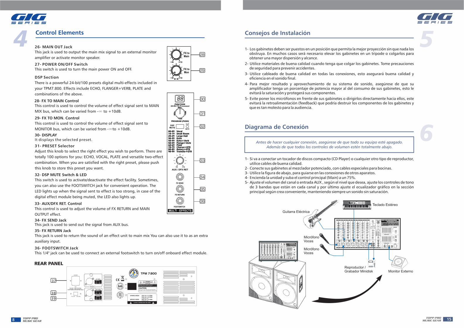
26- MAIN OUT Jack
This jack is used to output the main mix signal to an external monitor
amplifier or activate monitor speaker.
27- POWER ON/OFF Switch
This switch is used to turn the main power ON and OFF.
DSP Section
There is a powerful 24-bit/100 presets digital multi-effects included in
your TPM7.800. Effects include ECHO, FLANGER+VERB, PLATE and
combinations of the above.
28- FX TO MAIN Control
This control is used to control the volume of effect signal sent to MAIN
MIX bus, which can be varied from - to +10dB.
29- FX TO MON. Control
This control is used to control the volume of effect signal sent to
MONITOR bus, which can be varied from - to +10dB.
30- DISPLAYIt displays the selected preset.
31- PRESET Selector
Adjust this knob to select the right effect you wish to perform. There are
totally 100 options for you: ECHO, VOCAL, PLATE and versatile two-effect
combination. When you are satisfied with the right preset, please push
this knob to store this preset you want.
32- DSP MUTE Switch & LED
This switch is used to activate/deactivate the effect facility. Sometimes,
you can also use the FOOTSWITCH jack for convenient operation. The
LED lights up when the signal sent to effect is too strong, in case of the
digital effect module being muted, the LED also lights up.
34- FX SEND JackThis jack is used to send out the signal from AUX bus.
35- FX RETURN Jack
This jack is used to return the sound of an effect unit to main mix You can also use it to as an extra
auxiliary input.
36- FOOTSWITCH Jack
This 1/4" jack can be used to connect an external footswitch to turn on/off onboard effect module.
33- AUX/DFX RET. Control
This control is used to adjust the volume of FX RETURN and MAIN
OUTPUT effect.
110 127V- 220 240V-
AC INPUT
FUSE
110 127V 60Hz T6.3A 250V- ~220 240V 50Hz T3.15A 250V- ~
RATED POWER CONSUMPTION: 850W
OUTPUT 1
1+ 1-
POS NEG
LEFT/MAIN
BRIDGE
2+ 1+
POS NEG
BRIDGE MODE
RIGHT/MONO
OUTPUT 2
1+ 1-
POS NEG
OUTPUT 2
OUTPUT 1
SERIAL
MODEL
CAUTION:REPLACE WITH THE SAME TYPE FUSE AND RATINGDISCONNECT SUPPLY CORD BEFORE CHANGING FUSE
WARNING: SHOCK HAZARD- DO NOTOPEN
AVIS: RISQUE DE CHOC ELECTRIQUE- NE PAS OUVRIR
CAUTIONRISK OF ELECTRIC SHOCK
DO NOT OPEN
TPM 7.800
STEREO MODE: 400 W @ 4 OHM250 W @ 8 OHM(4 OHM MIN. LOAD)
BRIDGE MODE: 800 W @ 8 OHM(8 OHM MIN. LOAD)
CLASS 2 WIRING MAY BE USED
39
37
38
37- AC INPUT with FUSE Holder
Use it to connect your TPM to the main AC with the supplied AC cord. Please check the voltage
available in your country and how the voltage for your unit is configured before attempting to connect
your unit to the main AC.
7.800
38- VOLTAGE Selector
There are two kinds of voltages for your operation. From this switch you can select the voltage at
100~127VAC or 220~240VAC.
39- SPEAKERS Jacks
These jacks are used to connect speakers. They are configured with 4-way speakon connectors and
1/4" phone jacks. You can determine the signal that is output to these jacks according to the setting
of the AMPLIFIER MODE select switch.
Note: in order to avoid damage to the built-in amplifier, please pay attention to the allowed impedance
of the speaker. Very low load impedances may damage the amplifier.
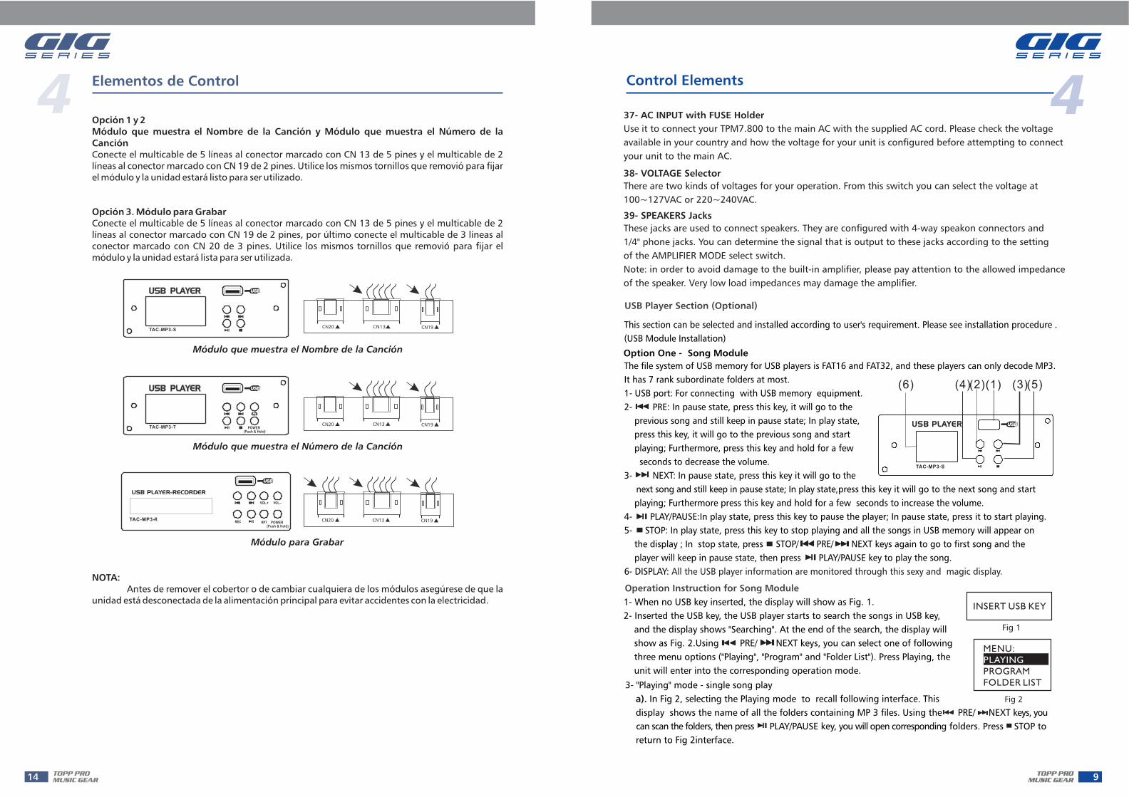
USB Player Section (Optional)
This section can be selected and installed according to user's requirement. Please see installation procedure .
(USB Module Installation)
The file system of USB memory for USB players is FAT16 and FAT32, and these players can only decode MP3.
It has 7 rank subordinate folders at most.
1- USB port: For connecting with USB memory equipment.
2- PRE: In pause state, press this key, it will go to the
previous song and still keep in pause state; In play state,
press this key, it will go to the previous song and start
playing; Furthermore, press this key and hold for a few
seconds to decrease the volume.
3- NEXT: In pause state, press this key it will go to the
next song and still keep in pause state; In play state,press this key it will go to the next song and start
playing; Furthermore press this key and hold for a few seconds to increase the volume.
4- PLAY/PAUSE:In play state, press this key to pause the player; In pause state, press it to start playing.
5- STOP: In play state, press this key to stop playing and all the songs in USB memory will appear on
the display ; In stop state, press STOP/ PRE/ NEXT keys again to go to first song and the
player will keep in pause state, then press PLAY/PAUSE key to play the song.
6- DISPLAY: All the USB player information are monitored through this sexy and magic display.
(1)(2) (3)(4) (5)(6)
TAC-MP3-S
USB PLAYER
Option One - Song Module
Operation Instruction for Song Module
1- When no USB key inserted, the display will show as Fig. 1.
2- Inserted the USB key, the USB player starts to search the songs in USB key,
and the display shows "Searching". At the end of the search, the display will
show as Fig. 2.Using PRE/ NEXT keys, you can select one of following
three menu options ("Playing", "Program" and "Folder List"). Press Playing, the
unit will enter into the corresponding operation mode.
INSERT USB KEY
Fig 1
MENU:
PROGRAM
FOLDER LIST
PLAYING
Fig 2
3- "Playing" mode - single song play
In Fig 2, selecting the Playing mode to recall following interface. This
display shows the name of all the folders containing MP 3 files. Using the PRE/ NEXT keys, you
can scan the folders, then press PLAY/PAUSE key, you will open corresponding folders. Press STOP to
return to Fig 2interface.
a).
FOLDER:
pop music
jazz music
classic music
Fig 3
PRE/ NEXT
PLAY/PAUSE
stop key. PLAY/PAUSE
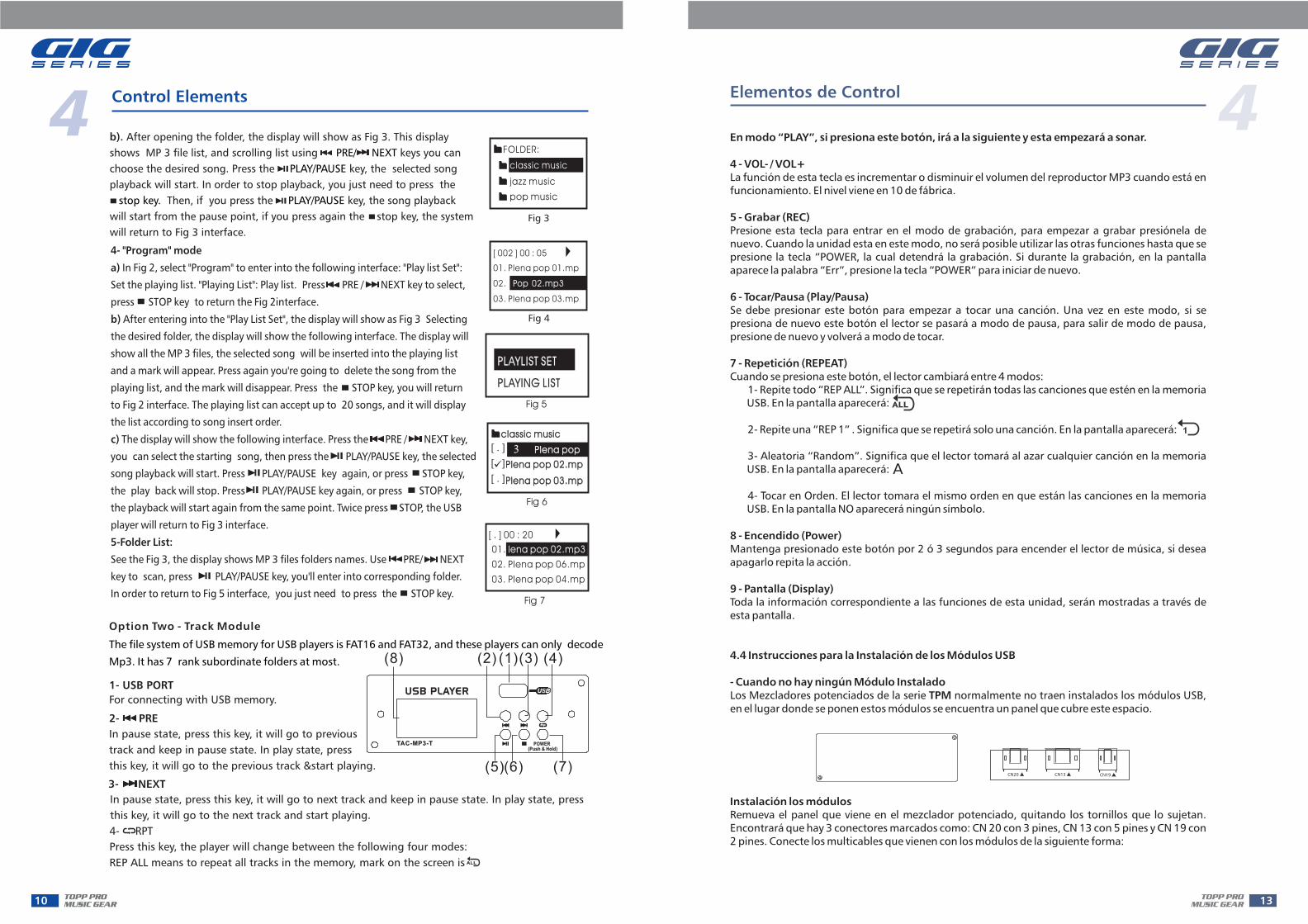
After opening the folder, the display will show as Fig 3. This display
shows MP 3 file list, and scrolling list using keys you can
choose the desired song. Press the key, the selected song
playback will start. In order to stop playback, you just need to press the
Then, if you press the key, the song playback
will start from the pause point, if you press again the stop key, the system
will return to Fig 3 interface.
b).
Fig 4
03. Plena pop 03.mp
02. Pop 02.mp3
01. Plena pop 01.mp
[ 002 ] 00 : 05
Fig 5
PLAYLIST SETPLAYLIST SET
PLAYING LISTPLAYING LIST
classic musicclassic music
Plena pop 03.mpPlena pop 03.mp
Plena pop 02.mpPlena pop 02.mp
Plena popPlena pop[ . ]p3
[ . ]
[ ]
Fig 6
Fig 7
03. Plena pop 04.mp
02. Plena pop 06.mp
01. lena pop 02.mp3
[ . ] 00 : 20
In Fig 2, select "Program" to enter into the following interface: "Play list Set":
Set the playing list. "Playing List": Play list. Press PRE / NEXT key to select,
press STOP key to return the Fig 2interface.
After entering into the "Play List Set", the display will show as Fig 3 Selecting
the desired folder, the display will show the following interface. The display will
show all the MP 3 files, the selected song will be inserted into the playing list
and a mark will appear. Press again you're going to delete the song from the
playing list, and the mark will disappear. Press the STOP key, you will return
to Fig 2 interface. The playing list can accept up to 20 songs, and it will display
the list according to song insert order.
The display will show the following interface. Press the PRE / NEXT key,
you can select the starting song, then press the PLAY/PAUSE key, the selected
song playback will start. Press PLAY/PAUSE key again, or press STOP key,
the play back will stop. Press PLAY/PAUSE key again, or press STOP key,
the playback will start again from the same point. Twice press STOP, the USB
player will return to Fig 3 interface.
PLAY/PAUSE key
4- "Program" mode
a)
b)
c)
5-Folder List:
See the Fig 3, the display shows MP 3 files folders names. Use PRE/ NEXT
key to scan, press , you'll enter into corresponding folder.
In order to return to Fig 5 interface, you just need to press the STOP key.
Option Two - Track Module
The file system of USB memory for USB players is FAT16 and FAT32, and these players can only decode
Mp3. It has 7 rank subordinate folders at most.
(5)(6) (7)
(1)(8) (3) (4)(2)
USB PLAYER
(Push & Hold)POWERTAC-MP3-T
1- USB PORT
For connecting with USB memory.
2- PRE
In pause state, press this key, it will go to previous
track and keep in pause state. In play state, press
this key, it will go to the previous track &start playing.
3- NEXT
In pause state, press this key, it will go to next track and keep in pause state. In play state, press
this key, it will go to the next track and start playing.
4- RPT
Press this key, the player will change between the following four modes:
REP ALL means to repeat all tracks in the memory, mark on the screen is
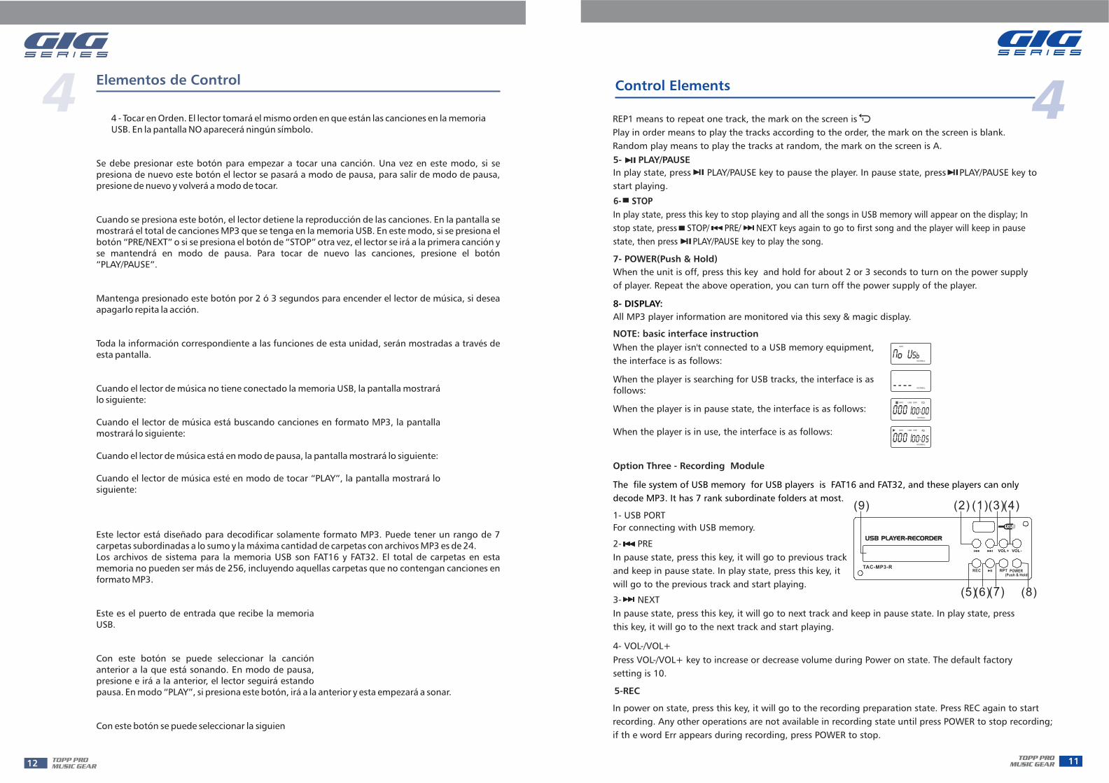
REP1 means to repeat one track, the mark on the screen is
Play in order means to play the tracks according to the order, the mark on the screen is blank.
Random play means to play the tracks at random, the mark on the screen is A.
All MP3 player information are monitored via this sexy & magic display.
5- PLAY/PAUSE
In play state, press PLAY/PAUSE key to pause the player. In pause state, press PLAY/PAUSE key to
start playing.
8- DISPLAY:
7- POWER(Push & Hold)
When the unit is off, press this key and hold for about 2 or 3 seconds to turn on the power supply
of player. Repeat the above operation, you can turn off the power supply of the player.
When the player is searching for USB tracks, the interface is asfollows:
NOTE: basic interface instruction
When the player isn't connected to a USB memory equipment,
the interface is as follows:
When the player is in pause state, the interface is as follows:
When the player is in use, the interface is as follows:
In play state, press this key to stop playing and all the songs in USB memory will appear on the display; In
stop state, press STOP/ PRE/ NEXT keys again to go to first song and the player will keep in pause
state, then press PLAY/PAUSE key to play the song.
6- STOP
Option Three - Recording Module
The file system of USB memory for USB players is FAT16 and FAT32, and these players can only
decode MP3. It has 7 rank subordinate folders at most.
(5)(6)(7)
(1)
(8)
(3)(4)(2)(9)
USB PLAYER-RECORDERUSB PLAYER-RECORDER
TAC-MP3-R
VOL+ VOL-
RPTREC(Push & Hold)
POWER
1- USB PORT
For connecting with USB memory.
2- PRE
In pause state, press this key, it will go to previous track
and keep in pause state. In play state, press this key, it
will go to the previous track and start playing.
3- NEXT
In pause state, press this key, it will go to next track and keep in pause state. In play state, press
this key, it will go to the next track and start playing.
4- VOL-/VOL+
Press VOL-/VOL+ key to increase or decrease volume during Power on state. The default factory
setting is 10.
In power on state, press this key, it will go to the recording preparation state. Press REC again to start
recording. Any other operations are not available in recording state until press POWER to stop recording;
if th e word Err appears during recording, press POWER to stop.
5-REC
Related Documents