TotalPac ® 3 Single interlock Preaction, Electric release Self-contained system 1 of 18 FM-076D-0-50G (Optional) DESCRIPTION This TOTALPAC ® 3 integrated fire protection system by FireFlex Systems Inc. consists of a preaction system trim totally pre- assembled, pre-wired and factory tested. All electrical and mechanical components of the system are contained in one single unit TOTALPAC ® 3 preaction systems are built around the Viking trim using deluge valves model F-1. Electrically operated, single interlock preaction system use an electric solenoid valve controlled by an approved system releasing control panel with a compatible detection system. In fire condition, when the detection condition is satisfied the system releasing control panel energizes the solenoid valve open, causing the deluge valve to open. If any sprinklers have opened, water will flow from the system. If sprinklers have not opened, water will be in the sprinkler system piping when the sprinkler operates. A sprinkler head must open before water flows from the system. All the valves are rated up to a maximum of 250 psi WWP (1724 kPa) max. and are available in the following diameters: 1½" (40 mm) 4" (100 mm) 2" (50 mm) 6" (150 mm) 3" (80 mm) 8" (200 mm) Standard features • cULus Listed & FM Approved as an assembled unit • Factory assembled, programmed and tested under ISO-9001 standards • Prewired to the Viking VFR-400 releasing control panel. • Easy and compact installation • Viking conventional trim rated at 250 psi (1724 kPa) • Galvanized trim piping • Serial number for easy reference • Corrosion resistant cabinet with flush type handle and lock • No open drain cup inside the unit • numerous modular options to meet the most demanding jobsite requirements • Four styles of modular air supply options • Inlet & outlet hydrostatic test ports • User-friendly standardized operation & installation manual • Free interactive simulator

Welcome message from author
This document is posted to help you gain knowledge. Please leave a comment to let me know what you think about it! Share it to your friends and learn new things together.
Transcript

TotalPac®3 Single interlock Preaction, Electric release
Self-contained system
1 of 18 FM-076D-0-50G
(Optional)
DESCRIPTION
This TOTALPAC®3 integrated fire protection system by FireFlex Systems Inc. consists of a preaction system trim totally pre-assembled, pre-wired and factory tested. All electrical and mechanical components of the system are contained in one single unit
TOTALPAC®3 preaction systems are built around the Viking trim using deluge valves model F-1.
Electrically operated, single interlock preaction system use an electric solenoid valve controlled by an approved system releasing control panel with a compatible detection system. In fire condition, when the detection condition is satisfied the system releasing control panel energizes the solenoid valve open, causing the deluge valve to open. If any sprinklers have opened, water will flow from the system. If sprinklers have not opened, water will be in the sprinkler system piping when the sprinkler operates. A sprinkler head must open before water flows from the system.
All the valves are rated up to a maximum of 250 psi WWP (1724 kPa) max. and are available in the following diameters:
1½" (40 mm) 4" (100 mm) 2" (50 mm) 6" (150 mm) 3" (80 mm) 8" (200 mm)
Standard features
• cULus Listed & FM Approved as an assembled unit
• Factory assembled, programmed and tested under ISO-9001 standards
• Prewired to the Viking VFR-400 releasing control panel.
• Easy and compact installation
• Viking conventional trim rated at 250 psi (1724 kPa)
• Galvanized trim piping
• Serial number for easy reference
• Corrosion resistant cabinet with flush type handle and lock
• No open drain cup inside the unit
• numerous modular options to meet the most demanding jobsite requirements
• Four styles of modular air supply options
• Inlet & outlet hydrostatic test ports
• User-friendly standardized operation & installation manual
• Free interactive simulator
TotalPac®3 Single interlock Preaction, Electric release
Self-contained system
FM-076D-0-50G 2 of 18
Cabinet
The TOTALPAC®3 cabinets are made of sturdy 14 gauge steel, they are available in four (4) sizes;
23" x 25" x 77" (58.4 x 63.5 x 195.6 cm) for 1½",and 2" systems,
36" x 25" x 77" (91.4 x 63.5 x 195.6 cm) for 3" and 4" system,
46" x 25" x 77" (116.8 x 63.5 x 195.6 cm) for 6" system
54" x 31" x 81" (137.2 x 78.7 x 205.7 cm) for 8" system
All surfaces are rust proof coated, inside and outside, with fire red, oven baked polyester powder on phosphate base. Cabinet is provided with one or two doors, all provided with a neoprene gasket to absorb vibrations.
A field wiring electrical junction boxes is integrated with the cabinet for connection of detection system, auxiliary contacts and signaling devices. All inputs & outputs are factory wired to a terminal strip (TBA) for contractor's field wiring.
Gauges to indicate air, water supply pressure and priming water pressure are all visible through clear Lexan windows. IMPORTANT: TOTALPAC®3 units are NOT designed to be installed where they will be subjected to outdoors and/or freezing conditions. Refer to environmental data for additional details. Subjecting the unit to conditions outside these limitations might tamper the normal operation of the system.
Cabinet doors are provided with hinges that can easily be disassembled on site to remove the door assemblies for servicing. The cabinet assembly is pre-assembled, pre-wired, and factory tested under ISO-9001 conditions.
Multiple unit installations are easily achieved by manifolding units together at their water inlets but drains shall remain separate and open.
Sequence of operation (see trim diagram)
In a fire condition, when the detection condition is satisfied, system releasing control panel activates an alarm and energizes normally closed solenoid valve (F1) open.
Pressure is released from the priming chamber of the deluge valve (A1) to the open drain manifold faster than it is supplied through the restricted orifice (B3). The Deluge Valve clapper opens to allow water to flow into the system piping and alarm devices, causing the alarm pressure switch (C1) and optional water motor alarm (C2) to activate. When a sprinkler head opens, water will flow from the system.
When the deluge valve operates, the sensing end of the PORV (B9) is pressurized, causing the PORV to open. When the PORV opens, it drains the priming water pressure to the priming chamber, preventing the deluge valve (A1) from resetting, even if the open releasing devices close. The deluge valve can only be reset after the system is taken out of service, and the outlet chamber of the deluge valve and associated trim piping is depressurized and drained.
Systems hydraulic limitations
WARNING The information contained herewith is for estimation and evaluation purposes only. Its use remains the responsibility of the designer. Designers should refer to the appropriate NFPA Standards and any other applicable codes for their final design. Also refer to FireFlex Systems Inc. appropriate user manuals and to manufacturer's data sheets for additional details. Systems limitations indicated below are nominal flow limitations.
System size (in.)
Usage Range (gpm)
Piping Equivalent Lengths w/o shut off valve
Piping Equivalent Lengths c/w shut off valve
Drain flow @ 250 PSIG w.p.
(m.) (ft.) (m.) (ft.) GPM 1½ 0 – 210 8.3 27.2 8.5 27.9 272 2 0 – 360 11.65 38.2 11.85 38.9 272 3 100 - 700 16.8 55.1 20.33 66.7 762 4 200 – 1400 21.89 71.8 25.33 83.1 1597 6 400 - 3500 33.28 109.15 37.28 122.3 1597 8 750 - 5250 41.15 135 44.71 146.7 1597
TotalPac®3 Single interlock Preaction, Electric release
Self-contained system
3 of 18 FM-076D-0-50G
Standard equipment
Releasing control panel
120 VAC / 60 Hz, 165VA. 220 VAC / 50 Hz, 185VA. 12VDC / 7Ah batteries. (factory installed) 12VDC / 12Ah batteries. (optional) Single Zone detection
(Activated by Zone 1 or Zone 2) Crossed-Zone detection
(Activated by Zone 1 and Zone 2)
The releasing control panel integrated into the TOTALPAC®3 cabinet is Viking's Model VFR-400. This panel includes four Class B, programmable detection zones (optional Class A); two Class B supervisory zones and four Class B, programmable output circuits (optional Class A). It is also provided with menu driven programming, including a specific program assigned at the factory. The panel is compatible with many types of fire alarm & supervisory devices such as linear heat detectors, spot-type heat and smoke detectors, water flow and release indicators, low and high air pressure switches, manual pull stations.
The releasing control panel also includes an alphanumeric display with 2 lines of 16 characters describing all the system conditions, as well as a set of red and yellow LED lamps individually indicating each of the alarm and trouble conditions of the system
Easy to operate control buttons are also provided to activate and operate the system's various functions.
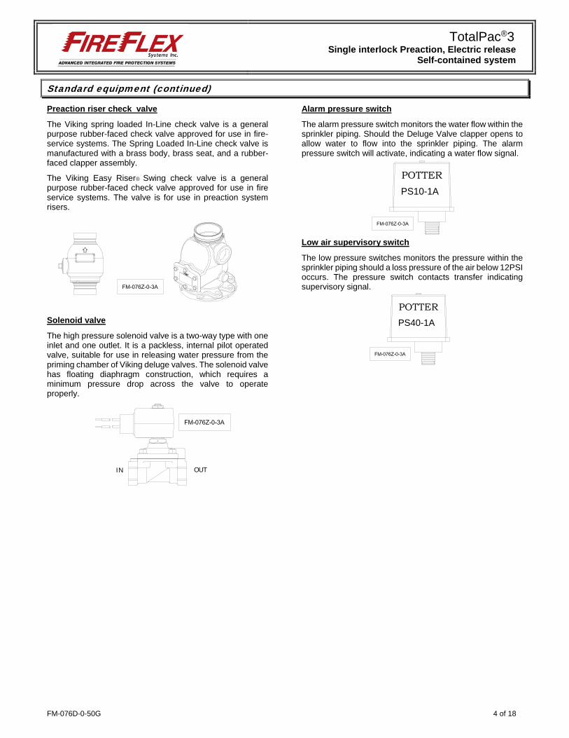
Releasing circuit disable switch
The releasing circuit disable switch is used to disable the releasing solenoid. When the key is set to “Disable”, the releasing solenoid will be disconnected from the control panel’s releasing circuit, causing a trouble signal and preventing accidental discharge during maintenance or inspection.
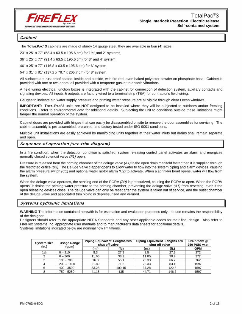
Deluge valve
The Viking Model deluge valve is a quick-opening, differential diaphragm, flood valve with one moving mechanism. The deluge valve is used to control water flow in deluge and preaction sprinkler systems. The valve is held closed by system water pressure trapped in the priming chamber, keeping the outlet chamber and system piping dry. In fire conditions, when the releasing system operates, pressure is released from the priming chamber. The deluge valve clapper opens to allow water to flow into the system piping.
Water supply control valve
The water inlet control valve is a supervised, indicating butterfly valve. Purpose of this vale is to manually shutoff the preaction system.
TotalPac®3 Single interlock Preaction, Electric release
Self-contained system
FM-076D-0-50G 4 of 18
Standard equipment (continued)
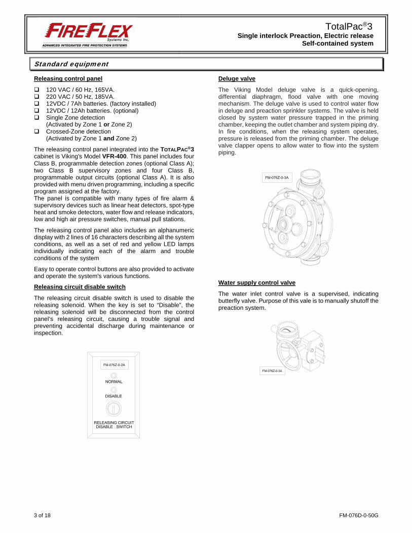
Preaction riser check valve
The Viking spring loaded In-Line check valve is a general purpose rubber-faced check valve approved for use in fire-service systems. The Spring Loaded In-Line check valve is manufactured with a brass body, brass seat, and a rubber-faced clapper assembly. The Viking Easy Riser® Swing check valve is a general purpose rubber-faced check valve approved for use in fire service systems. The valve is for use in preaction system risers.
Solenoid valve
The high pressure solenoid valve is a two-way type with one inlet and one outlet. It is a packless, internal pilot operated valve, suitable for use in releasing water pressure from the priming chamber of Viking deluge valves. The solenoid valve has floating diaphragm construction, which requires a minimum pressure drop across the valve to operate properly.
Alarm pressure switch
The alarm pressure switch monitors the water flow within the sprinkler piping. Should the Deluge Valve clapper opens to allow water to flow into the sprinkler piping. The alarm pressure switch will activate, indicating a water flow signal.
Low air supervisory switch
The low pressure switches monitors the pressure within the sprinkler piping should a loss pressure of the air below 12PSI occurs. The pressure switch contacts transfer indicating supervisory signal.
IN OUT
POTTERPS10-1A
POTTERPS40-1A
TotalPac®3 Single interlock Preaction, Electric release
Self-contained system
5 of 18 FM-076D-0-50G
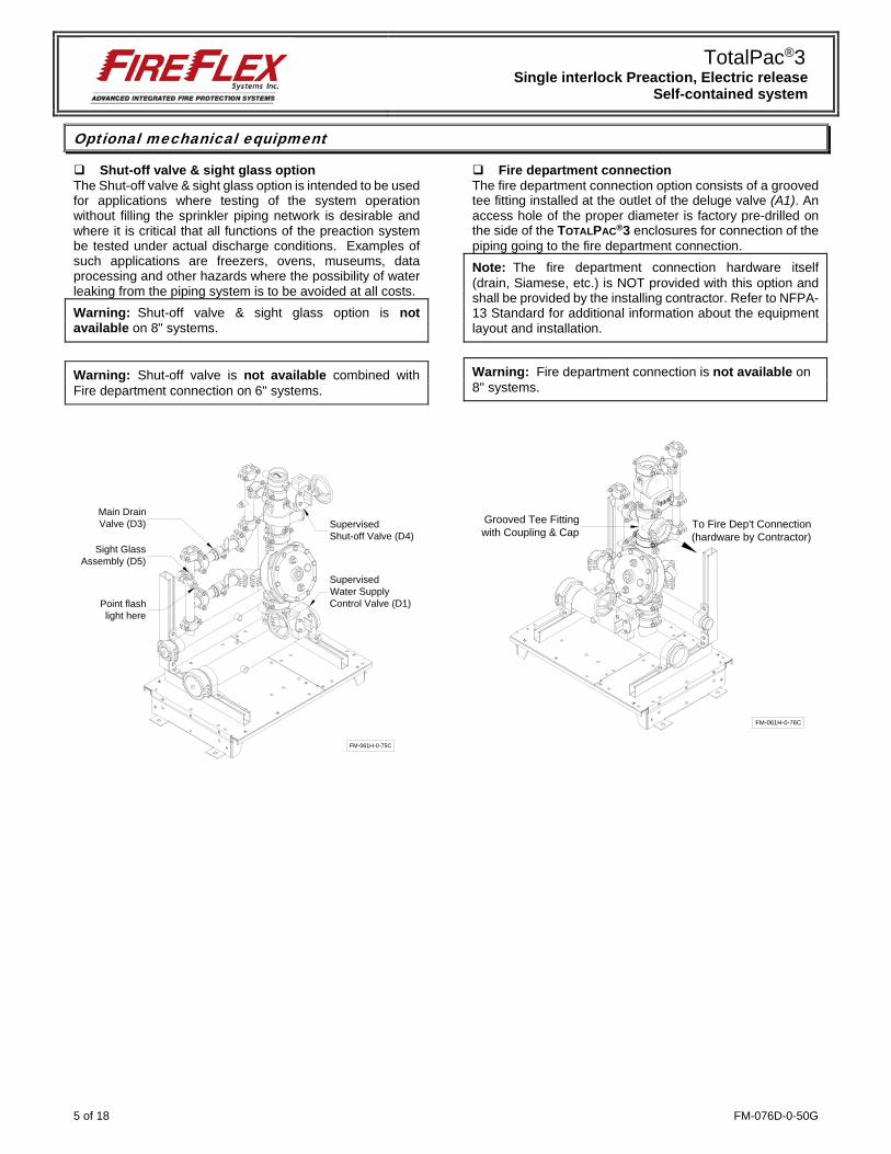
Optional mechanical equipment
Shut-off valve & sight glass option The Shut-off valve & sight glass option is intended to be used for applications where testing of the system operation without filling the sprinkler piping network is desirable and where it is critical that all functions of the preaction system be tested under actual discharge conditions. Examples of such applications are freezers, ovens, museums, data processing and other hazards where the possibility of water leaking from the piping system is to be avoided at all costs. Warning: Shut-off valve & sight glass option is not available on 8" systems.
Warning: Shut-off valve is not available combined with Fire department connection on 6" systems.
Fire department connection The fire department connection option consists of a grooved tee fitting installed at the outlet of the deluge valve (A1). An access hole of the proper diameter is factory pre-drilled on the side of the TOTALPAC®3 enclosures for connection of the piping going to the fire department connection. Note: The fire department connection hardware itself (drain, Siamese, etc.) is NOT provided with this option and shall be provided by the installing contractor. Refer to NFPA-13 Standard for additional information about the equipment layout and installation.
Warning: Fire department connection is not available on 8" systems.
Main DrainValve (D3) Supervised
Shut-off Valve (D4)Sight Glass
Assembly (D5)
Point flashlight here
SupervisedWater SupplyControl Valve (D1)
FM-061H-0-75C
Grooved Tee Fittingwith Coupling & Cap
FM-061H-0-76C
To Fire Dep't Connection(hardware by Contractor)

TotalPac®3 Single interlock Preaction, Electric release
Self-contained system
FM-076D-0-50G 6 of 18
Optional mechanical equipment (continued)
Semi and full flanged option When required by the user, TOTALPAC®3 units can be provided in either a semi-flanged of full flanged configuration. The semi flanged option provides flanged fittings only on the water inlet pipe (side needs to be specified at the time of order) and on the system riser outlet. The drain manifold is then provided with a threaded end that also needs to have its side specified (left or right). The rest of the fittings are the same as usual with the main components being provided in the standard grooved -grooved configuration. The full flanged option is the same as above but goes a step further with the main components being also provided with a flanged-flanged configuration. When provided, the face of the flanges will always be situated 6 inches from the outside face of the mounting base or cabinet surface.
Anti-column device option The model LD-1 anti-column device is an optional trim component designed for use with preaction sprinkler systems. The anti-column device automatically prevents an unwanted water column from establishing within the system riser. On preaction sprinkler systems the anti-column device prevents water from columning downstream of the easy riser check valve.
OSHPD option Pre-approved construction, under OSP-0341-10, using specific components.
Flanged fitting outside cabinet(when provided)
Flanged fitting outside cabinet(when provided)
Field connectionto Water Supply(specify side)
Threaded end
Field Connectionto Open Drain(specify side)
FM-061H-0-77C
From Sprinkler Riser
FM-061H-0-146ATo Drain Collector
TotalPac®3 Single interlock Preaction, Electric release
Self-contained system
7 of 18 FM-076D-0-50G
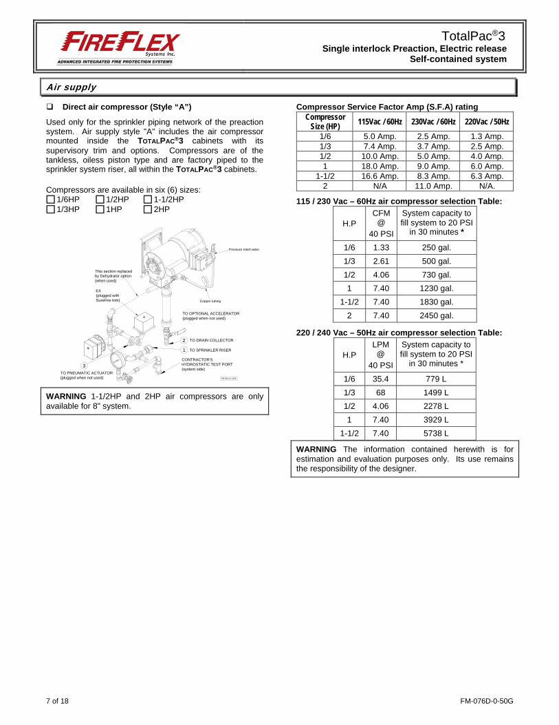
Air supply
Direct air compressor (Style “A”)
Used only for the sprinkler piping network of the preaction system. Air supply style "A" includes the air compressor mounted inside the TOTALPAC®3 cabinets with its supervisory trim and options. Compressors are of the tankless, oiless piston type and are factory piped to the sprinkler system riser, all within the TOTALPAC®3 cabinets.
Compressors are available in six (6) sizes: 1/6HP 1/2HP 1-1/2HP 1/3HP 1HP 2HP
WARNING 1-1/2HP and 2HP air compressors are only available for 8" system.
Compressor Service Factor Amp (S.F.A) rating Compressor
Size (HP) 115Vac / 60Hz 230Vac / 60Hz 220Vac / 50Hz
1/6 5.0 Amp. 2.5 Amp. 1.3 Amp. 1/3 7.4 Amp. 3.7 Amp. 2.5 Amp. 1/2 10.0 Amp. 5.0 Amp. 4.0 Amp. 1 18.0 Amp. 9.0 Amp. 6.0 Amp.
1-1/2 16.6 Amp. 8.3 Amp. 6.3 Amp. 2 N/A 11.0 Amp. N/A.
115 / 230 Vac – 60Hz air compressor selection Table:
H.P CFM
@ 40 PSI
System capacity to fill system to 20 PSI
in 30 minutes *
1/6 1.33 250 gal. 1/3 2.61 500 gal. 1/2 4.06 730 gal. 1 7.40 1230 gal.
1-1/2 7.40 1830 gal. 2 7.40 2450 gal.
220 / 240 Vac – 50Hz air compressor selection Table:
H.P LPM @
40 PSI
System capacity to fill system to 20 PSI
in 30 minutes *
1/6 35.4 779 L 1/3 68 1499 L 1/2 4.06 2278 L 1 7.40 3929 L
1-1/2 7.40 5738 L
WARNING The information contained herewith is for estimation and evaluation purposes only. Its use remains the responsibility of the designer.
FM-061H-0-118C
1
CONTRACTOR'SHYDROSTATIC TEST PORT(system side)
2 TO DRAIN COLLECTOR
TO SPRINKLER RISER
Copper tubing
This section replacedby Dehydrator option(when used)
TO OPTIONAL ACCELERATOR(plugged when not used)
3TO PNEUMATIC ACTUATOR(plugged when not used)
E4(plugged withSureFire trim)
Pressure relief valve
TotalPac®3 Single interlock Preaction, Electric release
Self-contained system
FM-076D-0-50G 8 of 18
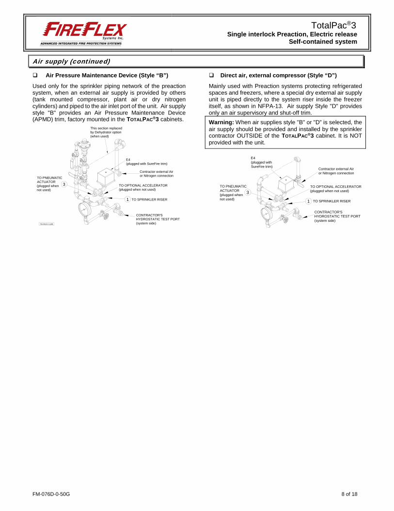
Air supply (continued)
Air Pressure Maintenance Device (Style “B”)
Used only for the sprinkler piping network of the preaction system, when an external air supply is provided by others (tank mounted compressor, plant air or dry nitrogen cylinders) and piped to the air inlet port of the unit. Air supply style "B" provides an Air Pressure Maintenance Device (APMD) trim, factory mounted in the TOTALPAC®3 cabinets.
Direct air, external compressor (Style “D”)
Mainly used with Preaction systems protecting refrigerated spaces and freezers, where a special dry external air supply unit is piped directly to the system riser inside the freezer itself, as shown in NFPA-13. Air supply Style "D" provides only an air supervisory and shut-off trim. Warning: When air supplies style "B" or "D" is selected, the air supply should be provided and installed by the sprinkler contractor OUTSIDE of the TOTALPAC®3 cabinet. It is NOT provided with the unit.
FM-061H-0-119B
1
CONTRACTOR'SHYDROSTATIC TEST PORT(system side)
TO SPRINKLER RISER
TO OPTIONAL ACCELERATOR(plugged when not used)
E4(plugged with SureFire trim)
This section replacedby Dehydrator option(when used)
Contractor external Airor Nitrogen connection
3TO PNEUMATICACTUATOR(plugged whennot used)
CONTRACTOR'SHYDROSTATIC TEST PORT(system side)
TO OPTIONAL ACCELERATOR(plugged when not used)
Contractor external Airor Nitrogen connection
3TO PNEUMATICACTUATOR(plugged whennot used) 1 TO SPRINKLER RISER
E4(plugged withSureFire trim)
TotalPac®3 Single interlock Preaction, Electric release
Self-contained system
9 of 18 FM-076D-0-50G
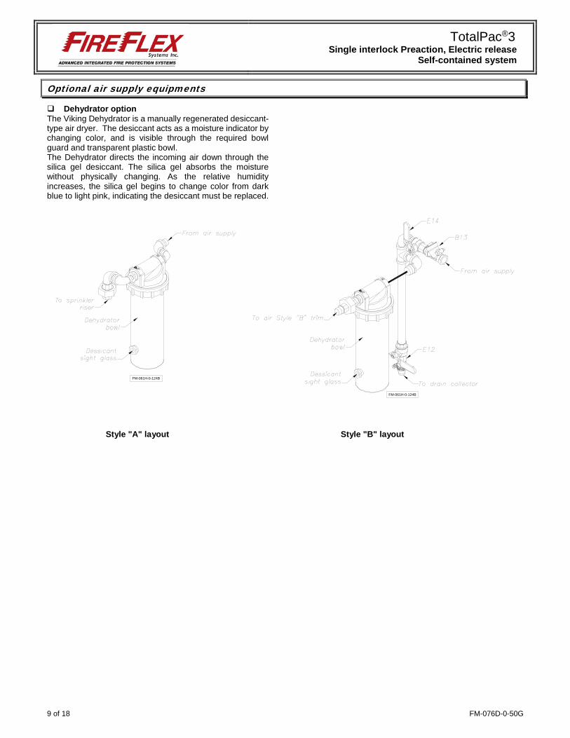
Optional air supply equipments
Dehydrator option The Viking Dehydrator is a manually regenerated desiccant-type air dryer. The desiccant acts as a moisture indicator by changing color, and is visible through the required bowl guard and transparent plastic bowl. The Dehydrator directs the incoming air down through the silica gel desiccant. The silica gel absorbs the moisture without physically changing. As the relative humidity increases, the silica gel begins to change color from dark blue to light pink, indicating the desiccant must be replaced.
Style "A" layout Style "B" layout
FM-061H-0-124B
FM-061H-0-124B
TotalPac®3 Single interlock Preaction, Electric release
Self-contained system
FM-076D-0-50G 10 of 18
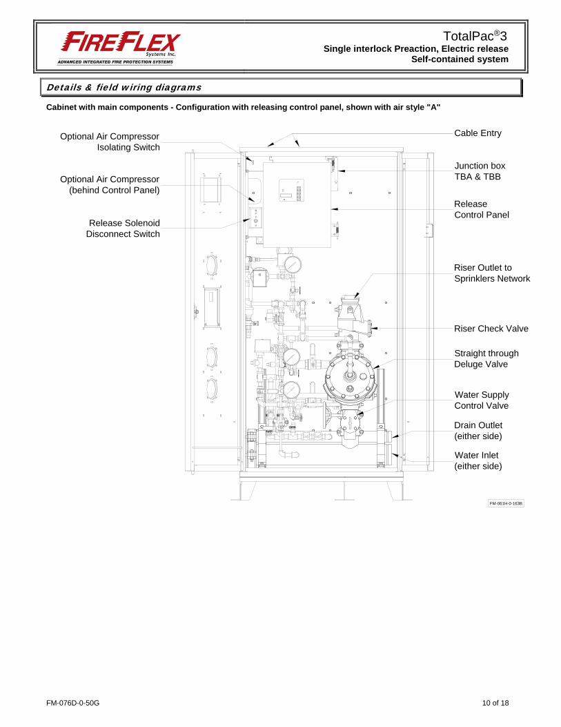
Details & field wiring diagrams
Cabinet with main components - Configuration with releasing control panel, shown with air style "A"
Junction boxTBA & TBB
ReleaseControl Panel
Release SolenoidDisconnect Switch
Optional Air CompressorIsolating Switch
Optional Air Compressor(behind Control Panel)
Riser Check Valve
Straight throughDeluge Valve
Water SupplyControl Valve
Riser Outlet toSprinklers Network
Cable Entry
Drain Outlet(either side)
Water Inlet(either side)
FM-061H-0-163B
TotalPac®3 Single interlock Preaction, Electric release
Self-contained system
11 of 18 FM-076D-0-50G
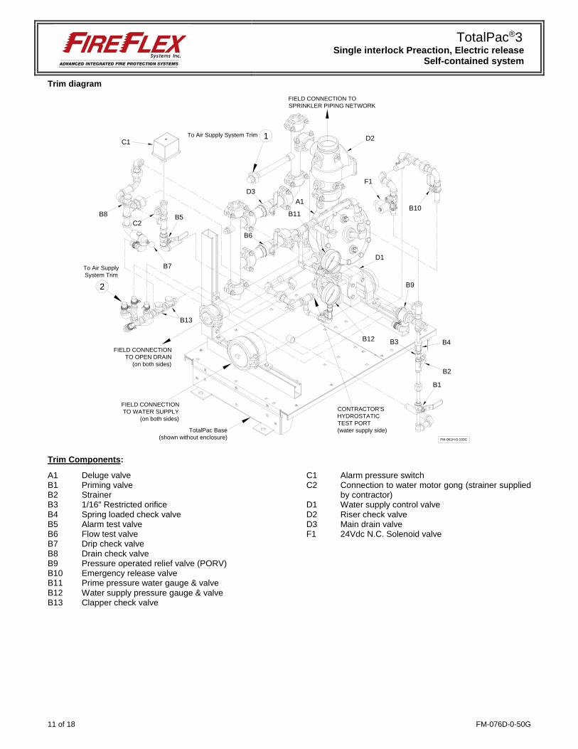
Trim diagram
Trim Components:
A1 Deluge valve B1 Priming valve B2 Strainer B3 1/16" Restricted orifice B4 Spring loaded check valve B5 Alarm test valve B6 Flow test valve B7 Drip check valve B8 Drain check valve B9 Pressure operated relief valve (PORV) B10 Emergency release valve B11 Prime pressure water gauge & valve B12 Water supply pressure gauge & valve B13 Clapper check valve
C1 Alarm pressure switch C2 Connection to water motor gong (strainer supplied
by contractor) D1 Water supply control valve D2 Riser check valve D3 Main drain valve F1 24Vdc N.C. Solenoid valve
FM-061H-0-103C
FIELD CONNECTIONTO OPEN DRAIN
(on both sides)
FIELD CONNECTIONTO WATER SUPPLY
(on both sides)
D1
C1
D3
B6
B5
B7
F1
B9
B1
B2
B4B3
D2
B13
A1
C2B11
B12
B10
2
CONTRACTOR'SHYDROSTATICTEST PORT(water supply side)
1To Air Supply System Trim
FIELD CONNECTION TOSPRINKLER PIPING NETWORK
TotalPac Base(shown without enclosure)
To Air SupplySystem Trim
B8
TotalPac®3 Single interlock Preaction, Electric release
Self-contained system
FM-076D-0-50G 12 of 18
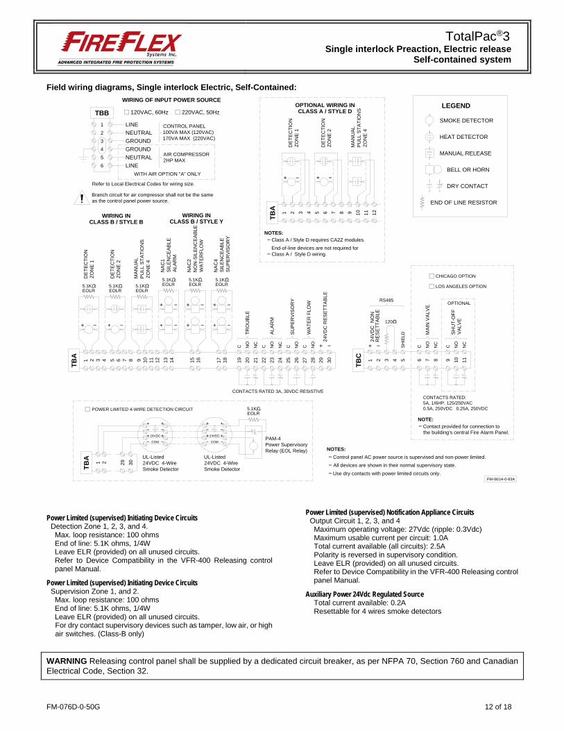
Field wiring diagrams, Single interlock Electric, Self-Contained:
Power Limited (supervised) Initiating Device Circuits Detection Zone 1, 2, 3, and 4. Max. loop resistance: 100 ohms End of line: 5.1K ohms, 1/4W Leave ELR (provided) on all unused circuits. Refer to Device Compatibility in the VFR-400 Releasing control panel Manual.
Power Limited (supervised) Initiating Device Circuits Supervision Zone 1, and 2. Max. loop resistance: 100 ohms End of line: 5.1K ohms, 1/4W Leave ELR (provided) on all unused circuits. For dry contact supervisory devices such as tamper, low air, or high air switches. (Class-B only)
Power Limited (supervised) Notification Appliance Circuits Output Circuit 1, 2, 3, and 4 Maximum operating voltage: 27Vdc (ripple: 0.3Vdc) Maximum usable current per circuit: 1.0A Total current available (all circuits): 2.5A Polarity is reversed in supervisory condition. Leave ELR (provided) on all unused circuits. Refer to Device Compatibility in the VFR-400 Releasing control panel Manual.
Auxiliary Power 24Vdc Regulated Source Total current available: 0.2A Resettable for 4 wires smoke detectors
WARNING Releasing control panel shall be supplied by a dedicated circuit breaker, as per NFPA 70, Section 760 and Canadian Electrical Code, Section 32.
FM-061H-0-83A
1
TBA
2 3 4 5 6 7 8 9 10 11 12
1234
TBB
56
1
TBA
2 3 4 5 6 7 8 9 10 11 12 13 14 15 16 17 18 19 20 21 22 23 24 25 26 27 28 29 30
EOLR5.1K
EOLR5.1K
EOLR5.1K EOLR
5.1KEOLR5.1K
EOLR5.1K
24V
DC
RES
ETTA
BLE
C NO
NC
C NO
NC
C NO
C NO
ALA
RM
TRO
UBL
E
SU
PE
RV
ISO
RY
WAT
ER F
LOW
DET
ECTI
ON
ZON
E 2
MAN
UAL
PU
LL S
TATI
ON
SZO
NE
4
NAC
1S
ILEN
CE
ABLE
ALA
RM
NAC
2N
ON
-SIL
ENC
EAB
LEW
ATER
FLO
W
NAC
4S
ILEN
CE
ABLE
SU
PE
RV
ISO
RY
DET
ECTI
ON
ZON
E 1
WIRING INCLASS B / STYLE B
DET
ECTI
ON
ZON
E 2
MAN
UAL
PU
LL S
TATI
ON
SZO
NE
4
DET
ECTI
ON
ZON
E 1
OPTIONAL WIRING INCLASS A / STYLE D
WIRING INCLASS B / STYLE Y
1
TBC
2 3 4 5
120
24VD
C N
ON
SH
IELD
RE
SE
TTAB
LE
RS485
LINENEUTRALGROUNDGROUNDNEUTRALLINE
120VAC, 60Hz 220VAC, 50Hz
CONTROL PANEL100VA MAX (120VAC)170VA MAX (220VAC)
AIR COMPRESSOR2HP MAX
CONTACTS RATED 3A, 30VDC RESISTIVE
WIRING OF INPUT POWER SOURCE
WITH AIR OPTION "A" ONLY
Branch circuit for air compressor shall not be the sameas the control panel power source.
6 7 8 9 10 11
C NO
NC
MA
IN V
ALVE
C NO
NC
SH
UT-
OFF
VA
LVE
Contact provided for connection tothe building's central Fire Alarm Panel.
OPTIONAL
LOS ANGELES OPTION
CHICAGO OPTION
NOTE:
Class A / Style D requires CA2Z modules.NOTES:
All devices are shown in their normal supervisory state.
NOTES:
Use dry contacts with power limited circuits only.
CONTACTS RATED:5A, 1/6HP, 125/250VAC0.5A, 250VDC 0.25A, 250VDC
HEAT DETECTOR
SMOKE DETECTOR
MANUAL RELEASE
DRY CONTACT
END OF LINE RESISTOR
LEGEND
BELL OR HORN
End-of-line devices are not required forClass A / Style D wiring.
Control panel AC power source is supervised and non-power limited.
Refer to Local Electrical Codes for wiring size.
1
TBA
2 29 30
24VDC
COM
EOLR5.1K
PAM-4Power SupervisoryRelay (EOL Relay)
UL-Listed24VDC 4-WireSmoke Detector
UL-Listed24VDC 4-WireSmoke Detector
24VDC
COM
POWER LIMITED 4-WIRE DETECTION CIRCUIT
TotalPac®3 Single interlock Preaction, Electric release
Self-contained system
13 of 18 FM-076D-0-50G
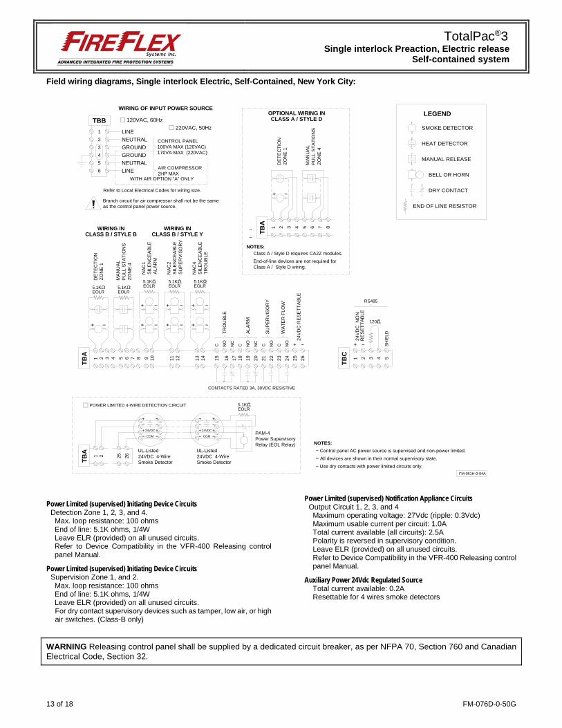
Field wiring diagrams, Single interlock Electric, Self-Contained, New York City:
Power Limited (supervised) Initiating Device Circuits Detection Zone 1, 2, 3, and 4. Max. loop resistance: 100 ohms End of line: 5.1K ohms, 1/4W Leave ELR (provided) on all unused circuits. Refer to Device Compatibility in the VFR-400 Releasing control panel Manual.
Power Limited (supervised) Initiating Device Circuits Supervision Zone 1, and 2. Max. loop resistance: 100 ohms End of line: 5.1K ohms, 1/4W Leave ELR (provided) on all unused circuits. For dry contact supervisory devices such as tamper, low air, or high air switches. (Class-B only)
Power Limited (supervised) Notification Appliance Circuits Output Circuit 1, 2, 3, and 4 Maximum operating voltage: 27Vdc (ripple: 0.3Vdc) Maximum usable current per circuit: 1.0A Total current available (all circuits): 2.5A Polarity is reversed in supervisory condition. Leave ELR (provided) on all unused circuits. Refer to Device Compatibility in the VFR-400 Releasing control panel Manual.
Auxiliary Power 24Vdc Regulated Source Total current available: 0.2A Resettable for 4 wires smoke detectors
WARNING Releasing control panel shall be supplied by a dedicated circuit breaker, as per NFPA 70, Section 760 and Canadian Electrical Code, Section 32.
EOLR5.1K
EOLR5.1K
EOLR5.1K
24V
DC
RES
ETTA
BLE
C NO
NC
C NO
NC
C NO
C NO
ALA
RM
TRO
UBL
E
SU
PE
RV
ISO
RY
WAT
ER F
LOW
MAN
UAL
PU
LL S
TATI
ON
SZO
NE
4
NAC
1S
ILEN
CE
ABLE
ALA
RM
NAC
2S
ILEN
CE
ABLE
SU
PE
RV
ISO
RY
NAC
4S
ILEN
CE
ABLE
TRO
UBL
E
DET
ECTI
ON
ZON
E 1
WIRING INCLASS B / STYLE B
WIRING INCLASS B / STYLE Y
1
TBC
2 3 4 5
120
24VD
C N
ON
SH
IELD
RE
SE
TTAB
LE
RS485
LINENEUTRALGROUNDGROUNDNEUTRALLINE
120VAC, 60Hz220VAC, 50Hz
CONTROL PANEL100VA MAX (120VAC)170VA MAX (220VAC)
AIR COMPRESSOR2HP MAX
CONTACTS RATED 3A, 30VDC RESISTIVE
WIRING OF INPUT POWER SOURCE
WITH AIR OPTION "A" ONLY
Branch circuit for air compressor shall not be the sameas the control panel power source.
Refer to Local Electrical Codes for wiring size.
1 2 3 4 5 6 7 8
MAN
UAL
PU
LL S
TATI
ON
SZO
NE
4
DET
ECTI
ON
ZON
E 1
OPTIONAL WIRING INCLASS A / STYLE D
Class A / Style D requires CA2Z modules.NOTES:
End-of-line devices are not required forClass A / Style D wiring.
FM-061H-0-84A
1234
TBB
56
1
TBA
2 3 4 5 6 7 8 9 10 11 12 13 14 15 16 17 18 19 20 21 22 23 24 25 26
EOLR5.1K
EOLR5.1K
TBA
All devices are shown in their normal supervisory state.
NOTES:
Use dry contacts with power limited circuits only.
Control panel AC power source is supervised and non-power limited.
1
TBA
2 25 26
24VDC
COM
EOLR5.1K
PAM-4Power SupervisoryRelay (EOL Relay)
UL-Listed24VDC 4-WireSmoke Detector
UL-Listed24VDC 4-WireSmoke Detector
24VDC
COM
POWER LIMITED 4-WIRE DETECTION CIRCUIT
HEAT DETECTOR
SMOKE DETECTOR
MANUAL RELEASE
DRY CONTACT
END OF LINE RESISTOR
LEGEND
BELL OR HORN
TotalPac®3 Single interlock Preaction, Electric release
Self-contained system
FM-076D-0-50G 14 of 18
Optional electrical equipments
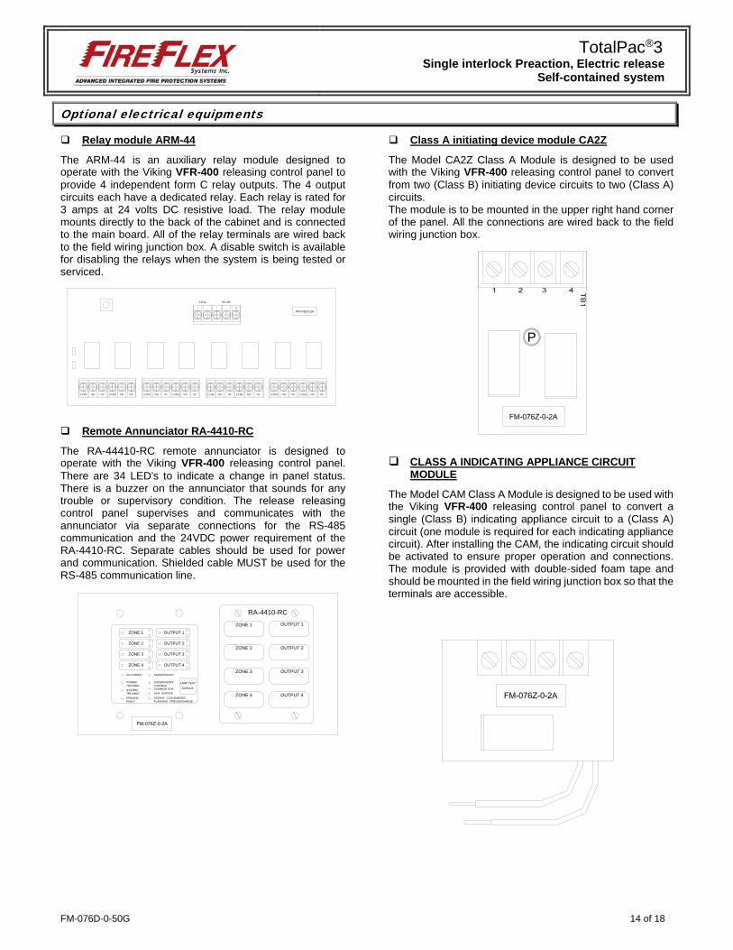
Relay module ARM-44
The ARM-44 is an auxiliary relay module designed to operate with the Viking VFR-400 releasing control panel to provide 4 independent form C relay outputs. The 4 output circuits each have a dedicated relay. Each relay is rated for 3 amps at 24 volts DC resistive load. The relay module mounts directly to the back of the cabinet and is connected to the main board. All of the relay terminals are wired back to the field wiring junction box. A disable switch is available for disabling the relays when the system is being tested or serviced.
Remote Annunciator RA-4410-RC
The RA-44410-RC remote annunciator is designed to operate with the Viking VFR-400 releasing control panel. There are 34 LED's to indicate a change in panel status. There is a buzzer on the annunciator that sounds for any trouble or supervisory condition. The release releasing control panel supervises and communicates with the annunciator via separate connections for the RS-485 communication and the 24VDC power requirement of the RA-4410-RC. Separate cables should be used for power and communication. Shielded cable MUST be used for the RS-485 communication line.
Class A initiating device module CA2Z
The Model CA2Z Class A Module is designed to be used with the Viking VFR-400 releasing control panel to convert from two (Class B) initiating device circuits to two (Class A) circuits. The module is to be mounted in the upper right hand corner of the panel. All the connections are wired back to the field wiring junction box.
CLASS A INDICATING APPLIANCE CIRCUIT
MODULE The Model CAM Class A Module is designed to be used with the Viking VFR-400 releasing control panel to convert a single (Class B) indicating appliance circuit to a (Class A) circuit (one module is required for each indicating appliance circuit). After installing the CAM, the indicating circuit should be activated to ensure proper operation and connections. The module is provided with double-sided foam tape and should be mounted in the field wiring junction box so that the terminals are accessible.
24Vdc RS-485
RA-4410-RCOUTPUT 1ZONE 1
OUTPUT 2ZONE 2
OUTPUT 3ZONE 3
OUTPUT 4ZONE 4
ZONE 1
ZONE 2
ZONE 3
ZONE 4
OUTPUT 1
OUTPUT 3
OUTPUT 4
OUTPUT 2
AC POWER
POWER TROUBLESYSTEMTROUBLEGROUNDFAULT
SUPERVISORYTROUBLE
STEADY : DISCHARGEDFLASHING : PRE-DISCHARGE
SUPERVISORY
COMMON ALM.ALM. SILENCE
LAMP TEST
SILENCE
P
TotalPac®3 Single interlock Preaction, Electric release
Self-contained system
15 of 18 FM-076D-0-50G
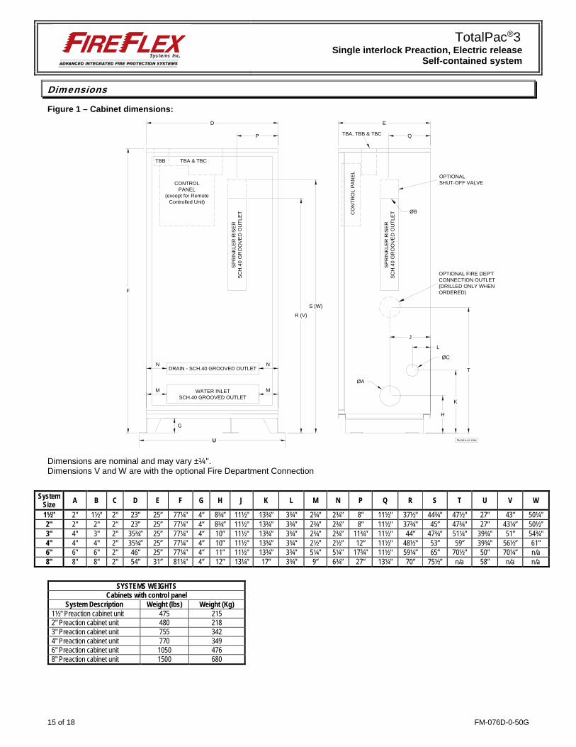
Dimensions
Figure 1 – Cabinet dimensions:
Dimensions are nominal and may vary ±¼". Dimensions V and W are with the optional Fire Department Connection
D
F
E
P
H
K
L
ØA
ØC
FM-061H-0-129A
WATER INLETSCH.40 GROOVED OUTLET
DRAIN - SCH.40 GROOVED OUTLET
SP
RIN
KLE
R R
ISE
RS
CH
.40
GR
OO
VE
D O
UTL
ET
OPTIONALSHUT-OFF VALVE
J
R (V)
S (W)
M M
T
SP
RIN
KLE
R R
ISE
RS
CH
.40
GR
OO
VE
D O
UTL
ET
Q
OPTIONAL FIRE DEP'TCONNECTION OUTLET(DRILLED ONLY WHENORDERED)
G
N N
TBB TBA & TBC
CO
NTR
OL
PA
NE
L
CONTROLPANEL
(except for RemoteControlled Unit)
TBA, TBB & TBC
ØB
U
System Size A B C D E F G H J K L M N P Q R S T U V W
1½" 2" 1½" 2" 23” 25” 77¼” 4” 8¾” 11½" 13¾” 3¾” 2¾” 2¾” 8” 11½" 37½" 44¾" 47½" 27” 43” 50¼” 2" 2" 2" 2" 23” 25” 77¼” 4” 8¾” 11½" 13¾” 3¾” 2¾” 2¾” 8” 11½" 37¾" 45” 47¾" 27” 43¼” 50½” 3" 4" 3" 2" 35¾” 25” 77¼” 4” 10” 11½" 13¾” 3¾” 2¾” 2¾” 11¾” 11½" 44” 47¾" 51¼” 39¾" 51” 54¾" 4" 4" 4" 2" 35¾” 25” 77¼” 4” 10” 11½" 13¾” 3¾” 2½” 2½” 12” 11½" 48½" 53” 59” 39¾" 56½” 61” 6" 6" 6" 2" 46” 25” 77¼” 4” 11” 11½" 13¾” 3¾” 5¼” 5¼” 17¾” 11½" 59¼” 65” 70½" 50” 70¼” n/a 8" 8" 8" 2" 54” 31” 81¼” 4” 12” 13¼” 17” 3¾” 9” 6¾” 27” 13¼” 70” 75½” n/a 58” n/a n/a
SYSTEMS WEIGHTS Cabinets with control panel
System Description Weight (lbs) Weight (Kg) 1½" Preaction cabinet unit 475 215 2" Preaction cabinet unit 480 218 3" Preaction cabinet unit 755 342 4" Preaction cabinet unit 770 349 6" Preaction cabinet unit 1050 476 8" Preaction cabinet unit 1500 680

TotalPac®3 Single interlock Preaction, Electric release
Self-contained system
FM-076D-0-50G 16 of 18
Figure 2 – Anchoring dimensions:
System
Size A B
1½” 25” 15"
2” 25” 15"
3” 37¾” 15"
4” 37¾” 15"
6" 48" 15"
8" 56" 21"
Figure 3 – Cabinet clearance dimensions
System
Size A B
1½” 24" 12”
2” 24" 12”
3” 24" 12”
4” 24" 12”
6" 24" 12”
8" 32" 12”
Figure 4 – Knockouts detail
5"
FM-061H-0-128A
A
FRONT
TOP VIEW
¾"
1"
B
A min.
B min.
TYPICALMECHANICAL
ROOM
FM-061H-0-130A
B min.
TOTALPACUNIT
3"
8½"
Top of Cabinet
FM-061H-0-68B-12
2½" Typ.3¾"
2½"
High voltage
Low voltage
TotalPac®3 Single interlock Preaction, Electric release
Self-contained system
17 of 18 FM-076D-0-50G
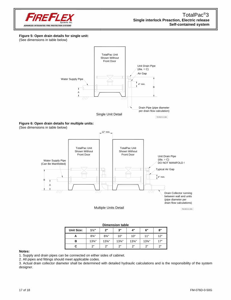
Figure 5: Open drain details for single unit: (See dimensions in table below)
Figure 6: Open drain details for multiple units: (See dimensions in table below)
Dimension table Unit Size: 1½" 2" 3" 4" 6" 8"
A 8¾" 8¾" 10" 10" 11" 12"
B 13¾" 13¾" 13¾" 13¾" 13¾" 17"
C 2" 2" 2" 2" 2" 2"
Notes: 1. Supply and drain pipes can be connected on either sides of cabinet. 2. All pipes and fittings should meet applicable codes. 3. Actual drain collector diameter shall be determined with detailed hydraulic calculations and is the responsibility of the system designer.
Air Gap
Water Supply Pipe
Unit Drain Pipe(dia. = C)
FM-061H-0-139A
A
B4'' min.
Drain Pipe (pipe diameterper drain flow calculation)
Single Unit Detail
TotalPac UnitShown Without
Front Door
FM-061H-0-140A
Drain Collector runningbetween wall and units(pipe diameter perdrain flow calculations)
Multiple Units Detail
A
B
Water Supply Pipe(Can Be Manifolded)
TotalPac UnitShown Without
Front Door
TotalPac UnitShown Without
Front Door
12'' min.
Typical Air Gap
Unit Drain Pipe(dia. = C)DO NOT MANIFOLD !
4'' min.

FM-076D-0-50G 18 of 18
1935, Lionel-Bertrand Blvd.
Boisbriand QC Canada J7H 1N8 Tel.: 450-437-3473 • Fax: 450-437-1930
Toll Free: 866-347-3353 Email: [email protected] • Web: www.fireflex.com
Related Documents