TotalPac ® 3 Wet pipe system c/w retard chamber 1 of 12 FM-076D-0-89C DESCRIPTION This TOTALPAC ® 3 integrated fire protection system by FireFlex Systems Inc. consists of an integrated wet type sprinkler riser assembly with retard chamber, totally pre-assembled, pre- wired and factory tested. All electrical and mechanical components of the system are contained in one single unit Standard wet Pipe systems are built around the Viking trim Alarm Check Valve Model J-1. The valves are rated up to a maximum of 250 psi WWP (1724 kPa) max and are available in the following diameters: 3" (100 mm) 4" (100 mm) 6" (150 mm) 8" (200 mm) Standard features • cULus Listed as an assembled unit • cULus Listed & FM Approved parts • Factory assembled, programmed and tested under ISO-9001 standards • Prewired to a terminal block • Easy and compact installation • Viking conventional trim rated at 250 psi (1724 kPa) • Galvanized trim piping • Serial number for easy reference • Corrosion resistant cabinet with flush type handle and lock • No open drain cup inside the unit • numerous modular options to meet the most demanding jobsite requirements • User-friendly standardized operation & installation manual • Free interactive simulator

Welcome message from author
This document is posted to help you gain knowledge. Please leave a comment to let me know what you think about it! Share it to your friends and learn new things together.
Transcript

TotalPac®3 Wet pipe system
c/w retard chamber
1 of 12 FM-076D-0-89C
DESCRIPTION
This TOTALPAC®3 integrated fire protection system by FireFlex Systems Inc. consists of an integrated wet type sprinkler riser assembly with retard chamber, totally pre-assembled, pre-wired and factory tested. All electrical and mechanical components of the system are contained in one single unit
Standard wet Pipe systems are built around the Viking trim Alarm Check Valve Model J-1. The valves are rated up to a maximum of 250 psi WWP (1724 kPa) max and are available in the following diameters:
3" (100 mm) 4" (100 mm)
6" (150 mm) 8" (200 mm)
Standard features
• cULus Listed as an assembled unit
• cULus Listed & FM Approved parts
• Factory assembled, programmed and tested under ISO-9001 standards
• Prewired to a terminal block
• Easy and compact installation
• Viking conventional trim rated at 250 psi (1724 kPa)
• Galvanized trim piping
• Serial number for easy reference
• Corrosion resistant cabinet with flush type handle and lock
• No open drain cup inside the unit
• numerous modular options to meet the most demanding jobsite requirements
• User-friendly standardized operation & installation manual
• Free interactive simulator
TotalPac®3 Wet pipe system
c/w retard chamber
FM-076D-0-89C 2 of 12
Cabinet
The TOTALPAC®3 cabinets are made of sturdy 14 gauge steel, they are available in two (2) sizes;
36" x 25" x 77" (91.4 x 63.5 x 195.6 cm) for 3" & 4”systems
46" x 25" x 77" (116.8 x 63.5 x 195.6 cm) for 6" systems
54" x 31" x 81" (137.2 x 78.7 x 205.7 cm) for 8” systems
All surfaces are rust proof coated, inside and outside, with fire red, oven baked polyester powder on phosphate base. Cabinet is provided with one or two doors, all provided with a neoprene gasket to absorb vibrations.
A field wiring electrical junction boxes is integrated with the cabinet for connection of all electrical components in the trim. Pressure switches, supervisory switches, etc. are all factory wired to a terminal strip (TBA) for contractor's field wiring.
Gauges to indicate air, water supply pressure and priming water pressure are all visible through clear Lexan windows.
IMPORTANT: TOTALPAC®3 units are NOT designed to be installed where they will be subjected to outdoors and/or freezing conditions. Refer to environmental data for additional details. Subjecting the unit to conditions outside these limitations might tamper the normal operation of the system.
Cabinet doors are provided with hinges that can easily be disassembled on site to remove the door assemblies for servicing. The cabinet assembly is pre-assembled, pre-wired, and factory tested under ISO-9001 conditions.
Multiple unit installations are easily achieved by manifolding units together at their water inlets but drains shall remain separate and open.
Sequence of operation (see trim diagram)
In a fire condition, the activation of at least one automatic sprinkler head is necessary to cause the water discharge. The activation of at least one automatic sprinkler head will trip the wet pipe valve and cause the system to spray through all open sprinklers. This will activate alarm and water flow switch contacts connected to the building fire alarm panel and sound an alarm.
Systems hydraulic limitations
WARNING The information contained herewith is for estimation and evaluation purposes only. Its use remains the responsibility of the designer. Designers should refer to the appropriate NFPA Standards and any other applicable codes for their final design. Also refer to FireFlex Systems Inc. appropriate user manuals and to manufacturer's data sheets for additional details. Systems limitations indicated below are nominal flow limitations.
System size (in.)
Usage Range (gpm)
Piping Equivalent Lengths Drain flow @ 250 PSIG w.p.
(m.) (ft.) GPM 3 125 - 700 20.76 68.1 762 4 250 - 1200 25.57 83.9 1581 6 750 - 2800 36.45 119.6 1581 8 750 - 5250 38.92 127.7 1581
TotalPac®3 Wet pipe system
c/w retard chamber
3 of 12 FM-076D-0-89C
Standard equipment
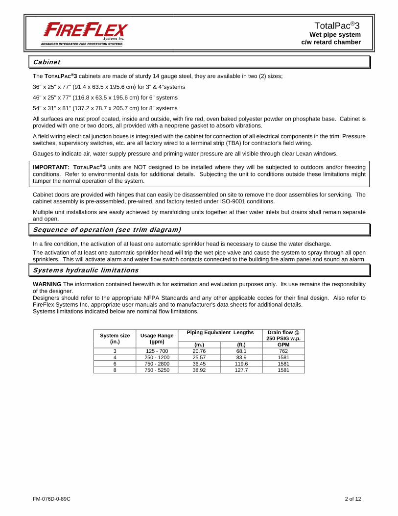
Alarm check valve
The Viking Model J-1 Alarm Check Valve serves as a check valve by trapping pressurized water above the clapper and preventing reverse flow from sprinkler piping. The valve is designed to initiate an alarm during a sustained flow of water (such as the flow required by an open sprinkler) by operating an optional water motor alarm and/or alarm pressure switch. The valve is made suitable for use on variable pressure water supplies by adding the optional retard chamber to the standard trim.
Water supply control valve The water inlet control valve is a supervised, indicating butterfly valve. Purpose of this vale is to manually shutoff the preaction system.
Retard Chamber
The Viking Model C-1 Retard Chamber is a surge tank used with Viking Alarm Check Valves to reduce the possibility of false alarms due to changes in the water supply pressure. When the clapper of the Alarm Check Valve opens, water flows through the restricted alarm line piping into the inlet of the Retard Chamber. The Retard Chamber begins to fill while simultaneously draining through the 1/8 inch (3.2 mm) Drain Restriction. During a sustained flow of water, the retard chamber fills faster than water can drain through the drain restriction. Pressurized water fills the retard chamber and pressurizes the alarm pressure switch. Pressure surge insufficient to overcome the volume and drain capacity of the retard chamber will not activate the alarm pressure switch.
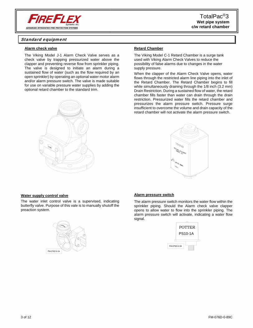
Alarm pressure switch
The alarm pressure switch monitors the water flow within the sprinkler piping. Should the Alarm check valve clapper opens to allow water to flow into the sprinkler piping. The alarm pressure switch will activate, indicating a water flow signal.
POTTERPS10-1A
TotalPac®3 Wet pipe system
c/w retard chamber
FM-076D-0-89C 4 of 12
Optional mechanical equipment
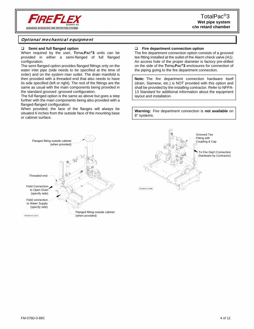
Semi and full flanged option When required by the user, TOTALPAC®3 units can be provided in either a semi-flanged of full flanged configuration. The semi flanged option provides flanged fittings only on the water inlet pipe (side needs to be specified at the time of order) and on the system riser outlet. The drain manifold is then provided with a threaded end that also needs to have its side specified (left or right). The rest of the fittings are the same as usual with the main components being provided in the standard grooved -grooved configuration. The full flanged option is the same as above but goes a step further with the main components being also provided with a flanged-flanged configuration. When provided, the face of the flanges will always be situated 6 inches from the outside face of the mounting base or cabinet surface.
Fire department connection option The fire department connection option consists of a grooved tee fitting installed at the outlet of the Alarm check valve (A1). An access hole of the proper diameter is factory pre-drilled on the side of the TOTALPAC®3 enclosures for connection of the piping going to the fire department connection.
Note: The fire department connection hardware itself (drain, Siamese, etc.) is NOT provided with this option and shall be provided by the installing contractor. Refer to NFPA-13 Standard for additional information about the equipment layout and installation.
Warning: Fire department connection is not available on 8" systems.
FM-061H-0-157A
Threaded end
Flanged fitting outside cabinet(when provided)
Field Connectionto Open Drain(specify side)
Field connectionto Water Supply
(specify side)
Flanged fitting outside cabinet(when provided)
To Fire Dep't Connection(hardware by Contractor)
Grooved TeeFitting withCoupling & Cap
FM-061H-0-158B
TotalPac®3 Wet pipe system
c/w retard chamber
5 of 12 FM-076D-0-89C
Details & field wiring diagrams
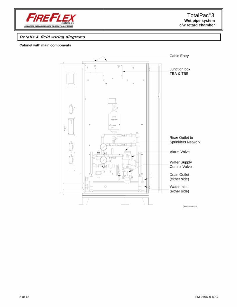
Cabinet with main components
FM-061H-0-203B
Junction boxTBA & TBB
Alarm Valve
Riser Outlet toSprinklers Network
Cable Entry
Water SupplyControl Valve
Drain Outlet(either side)
Water Inlet(either side)
TotalPac®3 Wet pipe system
c/w retard chamber
FM-076D-0-89C 6 of 12
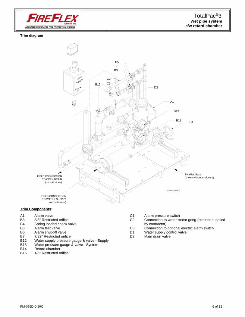
Trim diagram
Trim Components: A1 Alarm valve B3 3/8" Restricted orifice B4 Spring loaded check valve B5 Alarm test valve B6 Alarm shut-off valve B7 7/32" Restricted orifice B12 Water supply pressure gauge & valve - Supply B13 Water pressure gauge & valve - System B14 Retard chamber B15 1/8" Restricted orifice
C1 Alarm pressure switch C2 Connection to water motor gong (strainer supplied
by contractor) C3 Connection to optional electric alarm switch D1 Water supply control valve D3 Main drain valve
C2C3
B5
A1
D1
D3
B6B3
B15
B13
B12
FM-061H-0-116B
FIELD CONNECTIONTO OPEN DRAIN
(on both sides)
FIELD CONNECTIONTO WATER SUPPLY
(on both sides)
TotalPac Base(shown without enclosure)
TotalPac®3 Wet pipe system
c/w retard chamber
7 of 12 FM-076D-0-89C
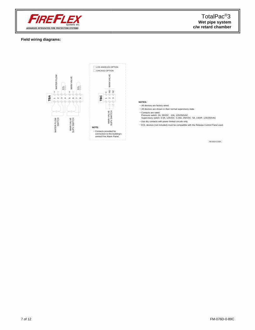
Field wiring diagrams:
FM-061H-0-99A
1
TBA
2 3 4 5 6 7 8
WA
TER
FLO
WW
ATE
R F
LOW
SW
ITC
H
EO
L
EO
L
MA
IN V
ALV
E S
UP
V S
WIT
CH
MA
IN V
ALV
E
1
TBC
2 3
C NO
NC
MA
IN V
ALV
E
Contacts provided forconnection to the building'scentral Fire Alarm Panel.
LOS ANGELES OPTION
CHICAGO OPTION
NOTE:
All devices are shown in their normal supervisory state.
NOTES:
Use dry contacts with power limited circuits only.
Contacts are rated:Pressure switch: 2A, 30VDC 10A, 125/250VACSupervisory switch: 0.5A, 125VDC 0.25A, 250VDC 5A, 1/6HP, 125/250VAC
EOL devices (not included) must be compatible with the Release Control Panel used.
All devices are factory wired.M
AIN
VA
LVE
SU
PV
SW
ITC
H
TotalPac®3 Wet pipe system
c/w retard chamber
FM-076D-0-89C 8 of 12
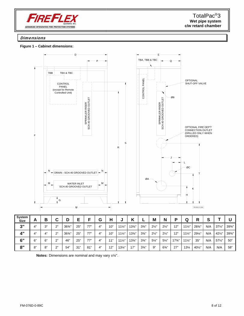
Dimensions
Figure 1 – Cabinet dimensions:
System
Size A B C D E F G H J K L M N P Q R S T U 3" 4" 3" 2" 36¾" 25" 77" 4" 10" 11½" 13¾" 3¾" 2½" 2½" 12" 11½" 28¾" N/A 37½" 39¾"
4" 4" 4" 2" 36¾" 25" 77" 4" 10" 11½" 13¾" 3¾" 2½" 2½" 12" 11½" 29¼" N/A 42½" 39¾"
6" 6" 6" 2" 46" 25" 77" 4" 11" 11½" 13¾" 3¾" 5¼" 5¼" 17¾" 11½" 35" N/A 57½" 50"
8" 8" 8" 2" 54” 31" 81" 4" 12" 13¼" 17" 3¾" 9" 6¾" 27" 13¼ 40½" N/A N/A 58"
Notes: Dimensions are nominal and may vary ±¼".
U
D
F
E
P
H
K
L
ØA
ØC
FM-061H-0-129A
WATER INLETSCH.40 GROOVED OUTLET
DRAIN - SCH.40 GROOVED OUTLET
SPR
INKL
ER R
ISER
SC
H.4
0 G
RO
OVE
D O
UTL
ET
OPTIONALSHUT-OFF VALVE
J
R
S
M M
T
SPR
INKL
ER R
ISER
SC
H.4
0 G
RO
OVE
D O
UTL
ET
Q
OPTIONAL FIRE DEP'TCONNECTION OUTLET(DRILLED ONLY WHENORDERED)
G
N N
TBB TBA & TBC
CO
NTR
OL
PAN
EL
CONTROLPANEL
(except for RemoteControlled Unit)
TBA, TBB & TBC
ØB
TotalPac®3 Wet pipe system
c/w retard chamber
9 of 12 FM-076D-0-89C
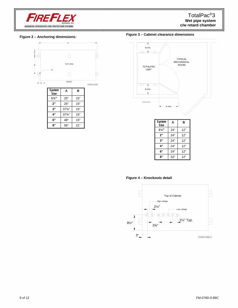
Figure 2 – Anchoring dimensions:
System
Size A B
1½” 25” 15"
2” 25” 15"
3” 37¾” 15"
4” 37¾” 15"
6" 48" 15"
8" 56" 21"
Figure 3 – Cabinet clearance dimensions
System
Size A B
1½” 24" 12”
2” 24" 12”
3” 24" 12”
4” 24" 12”
6" 24" 12”
8" 32" 12”
Figure 4 – Knockouts detail
5"
FM-061H-0-128A
A
FRONT
TOP VIEW
¾"
1"
B
A min.
B min.
TYPICALMECHANICAL
ROOM
FM-061H-0-130A
B min.
TOTALPACUNIT
3"
8½"
Top of Cabinet
FM-061H-0-68B-12
2½" Typ.3¾"
2½"
High voltage
Low voltage
TotalPac®3 Wet pipe system
c/w retard chamber
FM-076D-0-89C 10 of 12
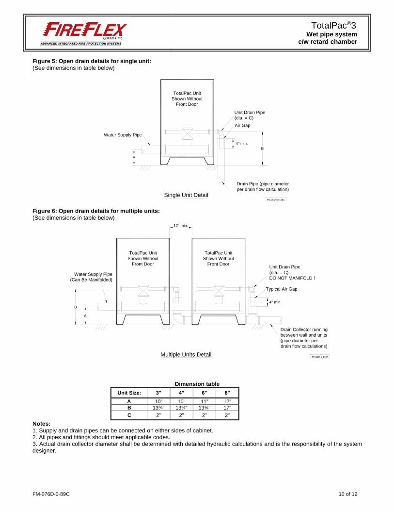
Figure 5: Open drain details for single unit: (See dimensions in table below)
Figure 6: Open drain details for multiple units: (See dimensions in table below)
Dimension table Unit Size: 3" 4" 6" 8"
A 10" 10" 11" 12" B 13¾" 13¾" 13¾" 17" C 2" 2" 2" 2"
Notes: 1. Supply and drain pipes can be connected on either sides of cabinet. 2. All pipes and fittings should meet applicable codes. 3. Actual drain collector diameter shall be determined with detailed hydraulic calculations and is the responsibility of the system designer.
Air Gap
Water Supply Pipe
Unit Drain Pipe(dia. = C)
FM-061H-0-139A
A
B4'' min.
Drain Pipe (pipe diameterper drain flow calculation)
Single Unit Detail
TotalPac UnitShown Without
Front Door
FM-061H-0-140A
Drain Collector runningbetween wall and units(pipe diameter perdrain flow calculations)
Multiple Units Detail
A
B
Water Supply Pipe(Can Be Manifolded)
TotalPac UnitShown Without
Front Door
TotalPac UnitShown Without
Front Door
12'' min.
Typical Air Gap
Unit Drain Pipe(dia. = C)DO NOT MANIFOLD !
4'' min.

TotalPac®3 Wet pipe system
c/w retard chamber
11 of 12 FM-076D-0-89C

FM-076D-0-89C 12 of 12
1935, Lionel-Bertrand Blvd.
Boisbriand QC Canada J7H 1N8 Tel.: 450-437-3473 • Fax: 450-437-1930
Toll Free: 866-347-3353 Email: [email protected] • Web: www.fireflex.com
Related Documents