ABB Motors / Cat. BA/M2BA GB 96-10 3 Totally enclosed squirrel cage three phase motors with cast iron frame Sizes 71 to 400, 0.25 to 710 kW Contents Page Mechanical design 4 Stator Drain holes Terminal box, connections Bearings Axially-locked bearing Transport locking Bearing seals Bearing life Pulley diameter Lubrication Permissible loadings on the shaft end Electrical design 14 t 6 -times Rating plates 14 Ordering information 15 Data tables, single-speed motors 16 Data tables, two-speed motors 24 Variant codes 30 Dimension drawings 36 Accessories 63 Cast iron motors in brief 68 ABB Motors product range 70 Cutaway view, M2BA 280 71 ABB Motors 73 ABB Motors reserves the right to change the design, technical specification and dimensions without prior notice.

Welcome message from author
This document is posted to help you gain knowledge. Please leave a comment to let me know what you think about it! Share it to your friends and learn new things together.
Transcript

ABB Motors / Cat. BA/M2BA GB 96-10 3
Totally enclosed squirrel cagethree phase motors with cast iron frameSizes 71 to 400, 0.25 to 710 kW
Contents
Page
Mechanical design 4StatorDrain holesTerminal box, connectionsBearingsAxially-locked bearingTransport lockingBearing sealsBearing lifePulley diameterLubricationPermissible loadings on the shaft end
Electrical design 14t6-times
Rating plates 14
Ordering information 15
Data tables, single-speed motors 16
Data tables, two-speed motors 24
Variant codes 30
Dimension drawings 36
Accessories 63
Cast iron motors in brief 68
ABB Motors product range 70
Cutaway view, M2BA 280 71
ABB Motors 73
ABB Motors reserves the right to changethe design, technical specification anddimensions without prior notice.

4 ABB Motors / Cat. BA/M2BA GB 96-10
Mechanical design
StatorThe motor frames including feet, bearing housing andterminal box are made of cast iron. Integrally cast feetallow a very rigid mounting and minimal vibration.
In the basic design, sizes 71 to 250 are suppliedwithout drain holes, although these can be provided asoption.
Motor sizes 280 to 400 are fitted with drain holes andplugs. The plugs are open on delivery. Check that thedrain holes and grease outlet face downwards, whenmounting designation differs from standard horizontalmounting.
Drain holes
Motors can be supplied for foot mounting, flangemounting and combinations of these.
In the case of vertical mounting, the upper plug must behammered home completely. In very dusty environ-ments, both plugs should be hammered home.
Terminal boxes are mounted either on the top of themotor, or on either side of the motor, see orderinginformation on page 15 and the table below.
Motors Terminal boxsize on top right side left side
71 normal - -80-132 normal on request on request160-400 normal on request on request
Terminal boxThe terminal box of motor sizes 71 to 250 can beturned 4x90° (as option in sizes 280 to 400) and inmotor sizes 280 to 400 rotated 2x180°, to allow cableentry from either side of the motor.
Degree of protection of standard terminal box is IP 55.
closed
open
open

ABB Motors / Cat. BA/M2BA GB 96-10 5
Co-ordination of terminal boxes andcable entries
Terminal box for motor sizes 160 to 250Terminal box for motor sizes 71 to 132
If no ordering information on the cable is given, it isassumed to be p.v.c. -insulated and termination partsare supplied according to the following tables.
Motor Terminal Max. rated Thread Max. size Cable Cablesize box current 6x... of conductor entry diameter
A mm2 mm mm
71 - 38 M4 6 2 x Pg 11 13.5 80, 90 - 38 M4 6 2 x Pg 16 16100, 112 - 71 M5 16 2 x Pg 21 20132 - 71 M5 16 2 x Pg 21 20
160 TB 20 94 M6 25 2 x Pg 29 28180 TB 20 94 M6 25 2 x Pg 29 28
200 TB 30 117 M8 35 2 x Pg 36 34225 TB 40 146 M8 50 2 x Pg 36 34250 TB 40 180 M10 70 2 x Pg 42 40
Motor sizes 71 to 250: Voltage 220 - 690 V, 50 Hz
Deviations from standard design according to thefollowing tables are available on request.
Non-standard design of terminal boxes; e.g. size,degree of protection, are available as options, seevariant codes page 34.
Motor sizes 71 to 250 are equipped with blank coverplates on delivery for connection flanges, but can beprovided with cable glands, see variant codes on page34.
In motor sizes 280 to 400 the terminal box is equippedwith cable glands or cable boxes as standard.
Terminations are suitable for Cu- and Al-cables (Al-cables on request for motor sizes 71 to 250). Cablesare connected to the terminals by cable lugs which arenot included with the motor.
To enable the supply of suitable terminations for themotor, please state cable type, quantity and size whenordering.
For dimension drawings of terminal boxes, see pages61-62.
6 ABB Motors / Cat. BA/M2BA GB 96-10
3000 r/min (2 poles) 1500 r/min (4 poles)
Voltage/Motor Term. Flange Cable Cable Term. Flange Cable Cable frequencyM2BA box box entry box box entry code
280 SM_ 122/2 MKLL 22/42 - 2xPg42 122/2 MKLL 22/42 - 2xPg42
315 SM_, ML_ 142/1 MKLL 32/48 - 2xPg48 142/1 MKLL 32/48 - 2xPg48
355 S 162/1 MPMM-ZL1 SK 172 1966 2xØ60 162/1 MPMM-ZL1 SK 172 1966 2xØ60 D142/2 - SK 172 1966 2xØ60 142/2 - SK 172 1966 2xØ60 E
355 SM_ 162/1 MPMM-ZL1 SK 172 1966 2xØ60 162/1 MPMM-ZL1 SK 172 1966 2xØ60355 ML_ 162/1 MPMM-ZL1 LNPB 3328 2xØ80 162/1 MPMM-ZL1 LNPB 3328 2xØ80
400 M_ 162/1 MPMM-ZL1 LNPB 3328 2xØ80 162/1 MPMM-ZL1 LNPB 3328 2xØ80
400 LKA 162/2 MPMM-ZL1 LNPB 3328 2xØ80 162/2 MPMM-ZL1 LNPB 3328 2xØ80 D162/2 MPMM-ZL1 LNPB 3328 2xØ80 162/1 MPMM-ZL1 LNPB 3328 2xØ80 E
400 LKB 162/2 MPMM-ZL1 LNPB 3328 2xØ80 162/2 MPMM-ZL1 LNPB 3328 2xØ80400 LKC - - - - 162/2 MPMM-ZL1 LNPB 3328 2xØ80
1000 r/min (6 poles) 750 r/min (8 poles)
Voltage/Motor Term. Flange Cable Cable Term. Flange Cable Cable frequencyM2BA box box entry box box entry code
280 SMA, SMB 122/2 MKLL 22/36 - 2xPg36 122/2 MKLL 22/36 - 2xPg36280 SMC 122/2 MKLL 22/42 - 2xPg42 122/2 MKLL 22/36 - 2xPg36
315 SM_ 142/1 MKLL 32/42 - 2xPg42 142/1 MKLL 32/42 - 2xPg42315 ML_ 142/1 MKLL 32/48 - 2xPg48 142/1 MKLL 32/48 - 2xPg48
355 S 142/2 - SK 172 1966 2xØ60 142/2 - SK 172 1966 2xØ60
355 SMA 142/2 - SK 172 1966 2xØ60 142/2 - SK 172 1966 2xØ60355 SMB 162/1 MPMM-ZL 1 SK 172 1966 2xØ60 - - - - D355 SMB 142/2 - SK 172 1966 2xØ60 - - - - E
355 MLA 162/1 MPMM-ZL 1 SK 172 1966 2xØ60 142/2 - SK 172 1966 2xØ60355 MLC 162/1 MPMM-ZL 1 SK 172 1966 2xØ60 162/1 MPMM-ZL 1 SK 172 1966 2xØ60 D355 MLC 162/1 MPMM-ZL 1 SK 172 1966 2xØ60 142/2 - SK 172 1966 2xØ60 E
400 M 162/1 MPMM-ZL 1 LNPB 3328 2xØ80 142/2 - SK 172 1966 2xØ60 D400 M 142/2 - SK 172 1966 2xØ60 142/2 - SK 172 1966 2xØ60 E
400 MA 162/1 MPMM-ZL 1 LNPB 3328 2xØ80 162/1 MPMM-ZL 1 SK 172 1966 2xØ60 D400 MA 162/1 MPMM-ZL 1 LNPB 3328 2xØ80 142/2 - SK 172 1966 2xØ60 E400 MB 162/1 MPMM-ZL 1 LNPB 3328 2xØ80 - - - -
400 LKA 162/1 MPMM-ZL 1 LNPB 3328 2xØ80 162/1 MPMM-ZL 1 LNPB 3328 2xØ80
400 LKB 162/2 MPMM-ZL 1 LNPB 3328 2xØ80 162/1 MPMM-ZL 1 LNPB 3328 2xØ80 D162/1 MPMM-ZL 1 LNPB 3328 2xØ80 162/1 MPMM-ZL 1 LNPB 3328 2xØ80 E
400 LKC 162/2 MPMM-ZL 1 LNPB 3328 2xØ80 - - - - D162/1 MPMM-ZL 1 LNPB 3328 2xØ80 - - - - E
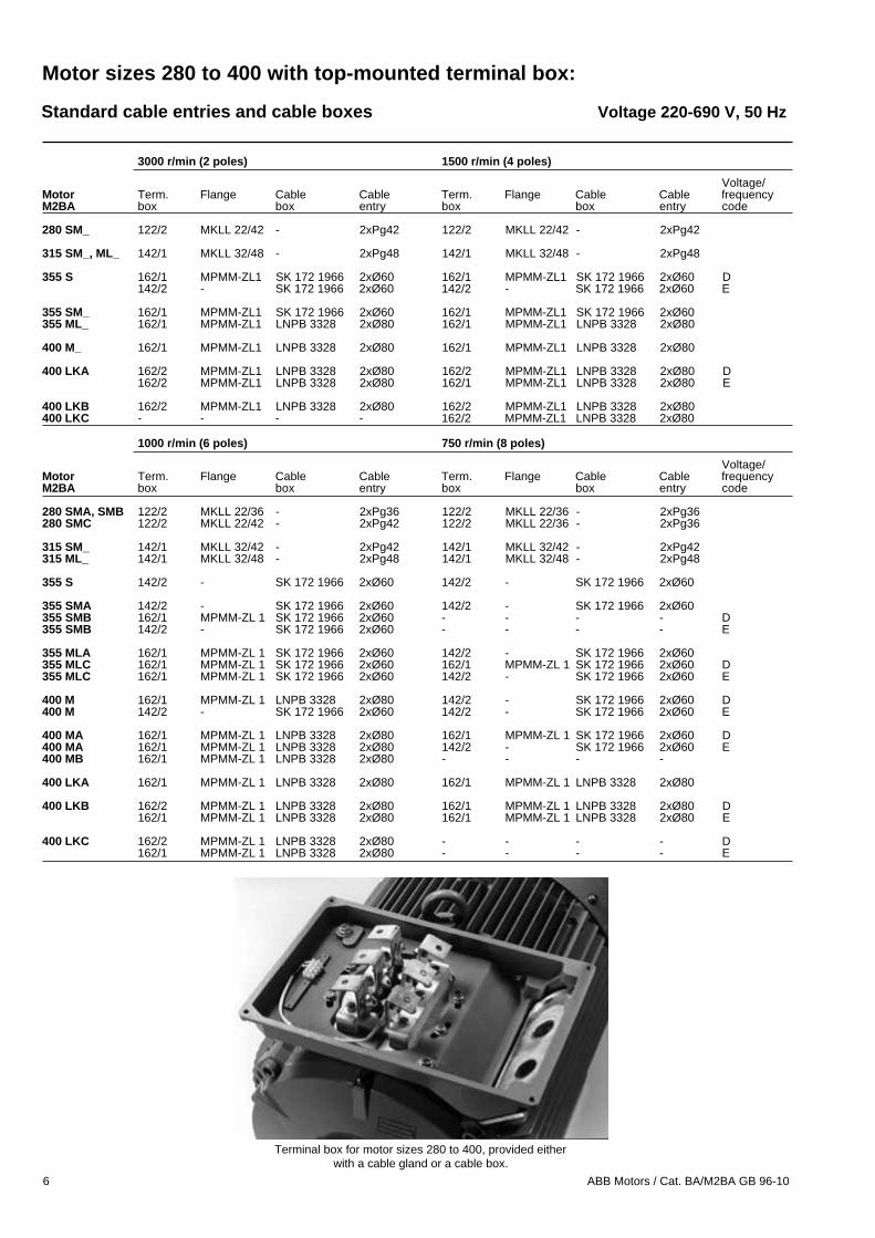
Motor sizes 280 to 400 with top-mounted terminal box:
Standard cable entries and cable boxes Voltage 220-690 V, 50 Hz
Terminal box for motor sizes 280 to 400, provided eitherwith a cable gland or a cable box.

ABB Motors / Cat. BA/M2BA GB 96-10 7
3000 r/min (2 poles) 1500 r/min (4 poles)
Voltage/Motor Term. Flange Cable Cable Term. Flange Cable Cable frequencyM2BA box box entry box box entry code
280 SM_ 122/7 MKLL 22/42 - 2xPg42 122/7 MKLL 22/42 - 2xPg42
315 SM_, ML_ 142/5 MKLL 32/48 - 2xPg48 142/5 MKLL 32/48 - 2xPg48
355 S 162/5 MKPD 3425 SK 172 1966 2xØ60 162/5 MKPD 3425 SK 172 1966 2xØ60 D142/10 - SK 172 1966 2xØ60 142/10 - SK 172 1966 2xØ60 E
355 SM_ 162/5 MKPD 3425 SK 172 1966 2xØ60 162/5 MKPD 3425 SK 172 1966 2xØ60355 ML_ 162/5 MKPD 3425 LNPB 3328 2xØ80 162/5 MKPD 3425 LNPB 3328 2xØ80
400 M_ 162/5 MKPD 3425 LNPB 3328 2xØ80 162/5 MKPD 3425 LNPB 3328 2xØ80
400 LKA 162/8 MKPD 3425 LNPB 3328 2xØ80 162/8 MKPD 3425 LNPB 3328 2xØ80 D162/8 MKPD 3425 LNPB 3328 2xØ80 162/5 MKPD 3425 LNPB 3328 2xØ80 E
400 LKB 162/8 MKPD 3425 LNPB 3328 2xØ80 162/8 MKPD 3425 LNPB 3328 2xØ80400 LKC - - - - 162/8 MKPD 3425 LNPB 3328 2xØ80
1000 r/min (6 poles) 750 r/min (8 poles)
Voltage/Motor Term. Flange Cable Cable Term. Flange Cable Cable frequencyM2BA box box entry box box entry code
280 SMA, SMB 122/7 MKLL 22/36 - 2xPg36 122/7 MKLL 22/36 - 2xPg36280 SMC 122/7 MKLL 22/42 - 2xPg42 122/7 MKLL 22/36 - 2xPg36
315 SM_ 142/5 MKLL 32/42 - 2xPg42 142/5 MKLL 32/42 - 2xPg42315 ML_ 142/5 MKLL 32/48 - 2xPg48 142/5 MKLL 32/48 - 2xPg48
355 S 142/10 - SK 172 1966 2xØ60 142/10 - SK 172 1966 2xØ60
355 SMA 142/10 - SK 172 1966 2xØ60 142/10 - SK 172 1966 2xØ60355 SMB 162/5 MKPD 3425 SK 172 1966 2xØ60 - - - - D355 SMB 142/10 - SK 172 1966 2xØ60 - - - - E
355 MLA 162/5 MKPD 3425 SK 172 1966 2xØ60 142/10 - SK 172 1966 2xØ60355 MLC 162/5 MKPD 3425 SK 172 1966 2xØ60 162/5 MKPD 3425 SK 172 1966 2xØ60 D355 MLC 162/5 MKPD 3425 SK 172 1966 2xØ60 142/10 - SK 172 1966 2xØ60 E
400 M 162/5 MKPD 3425 LNPB 3328 2xØ80 142/10 - SK 172 1966 2xØ60 D400 M 142/10 - SK 172 1966 2xØ60 142/10 - SK 172 1966 2xØ60 E
400 MA 162/5 MKPD 3425 LNPB 3328 2xØ80 162/5 MKPD 3425 SK 172 1966 2xØ60 D400 MA 162/5 MKPD 3425 LNPB 3328 2xØ80 142/10 - SK 172 1966 2xØ60 E400 MB 162/5 MKPD 3425 LNPB 3328 2xØ80 - - - -
400 LKA 162/5 MKPD 3425 LNPB 3328 2xØ80 162/5 MKPD 3425 LNPB 3328 2xØ80
400 LKB 162/8 MKPD 3425 LNPB 3328 2xØ80 162/5 MKPD 3425 LNPB 3328 2xØ80 D162/5 MKPD 3425 LNPB 3328 2xØ80 162/5 MKPD 3425 LNPB 3328 2xØ80 E
400 LKC 162/8 MKPD 3425 LNPB 3328 2xØ80 - - - - D162/5 MKPD 3425 LNPB 3328 2xØ80 - - - - E
Motor sizes 280 to 400 with side-mounted terminal box
Standard cable entries and cable boxes Voltage 220-690 V, 50 Hz
Voltage/frequency codes:D - 380-420 VD 50 Hz, 660-690 VY 50 Hz, 440-480 VD 60 HzE - 500 VD 50 Hz, 575 VD 60 Hz
The following examples explain the terminal box codings in the table above:
122/2 MKLL 22/42 - terminal box 122/2- flange MKLL 22/42- cable gland 2 x Pg 42
162/1 MPMM-ZL 1 SK 172 1966 2xØ60 - terminal box 162/1- adaptor MPMM-ZL 1- cable box SK 172 1966- cable entry 2xØ60
162/5 MKPD 3425 LNPB 3328 2xØ80 - terminal box 162/5- adaptor MKPD 3425- cable box LNPB 3328- cable entry 2xØ80
See drawings on the following page and on page 62.

8 ABB Motors / Cat. BA/M2BA GB 96-10
Motor sizes 280 to 400:
Alternatives for cable entries and cable boxes
The tables on pages 6 and 7 show the standardterminal boxes and termination parts that are deliveredwhen no information on the cable is given.
The table below shows the different alternativesavailable for cable boxes and cable entries. Other typeson request.
Motor Terminal box Opening Max. rated Max.size Cable Cable Blanksize on top on type current A of conductor gland box plate
side (D/Y-conn.) mm2
280 122/2 122/7 C (FL 21) 363/210 2x150 2xPg29...42 1xØ36...52/Ø48...60 MKLN 20
315 142/1 142/5 D (FL33) 640/370 2x240 1xPg36...42 1xØ36...52/Ø48...60 MKLN 302xPg36...48 2xØ48...60/Ø50...68
2xØ68.. .80
355, 400 142/2 142/10 D (FL33) 640/370 2x240 1xPg36...42 1xØ36...52/Ø48...60 MKLN 302xPg36...48 2xØ48...60/Ø50...68
2xØ68.. .80
162/1 162/5 E-D 1) 950/550 4x240 2xPg36...48 1xØ36...52/Ø48...601xPg36...42 2xØ48...60/Ø50...68
2xØ68.. .80
162/2 162/8 E-D 1) 1300/750 4x240 2xPg36...48 1xØ36...52/Ø48...601xPg36...42 2xØ48...60/Ø50...68
2xØ68.. .80
162/1 162/5 E-2D 1) 950/550 4x240 2x2xPg36...48 2x1xØ36...52/Ø48...602x1xPg36...42 2x2xØ48...60/Ø50...68
2x2xØ68.. .80
162/2 162/8 E-2D 1) 1300/750 4x240 2x2xPg36...48 2x1xØ36...52/Ø48...602x1xPg36...42 2x2xØ48...60/Ø50...68
2x2xØ68.. .80
1)Terminal box type 162 is used with a combination of one E-opening and one or two D-openings,see pictures below and on page 62.
D-openings
E-opening
Adaptor E - D
Terminal box 162 with adapting flange MPMM-ZL 1: Terminal box 162 with adapting flange MKPD 3425:
Opening c e f g d
C (FL 21) 62 193 62 193 M8
D (FL 33) 100 300 80 292 M10
E (FL 40) 115 370 100 360 M12

ABB Motors / Cat. BA/M2BA GB 96-10 9
Bearings
Standard version with deep groove Version with roller bearings,Motor Number ball bearings Variant code 037, page 30.size of poles D-end N-end D-end
71 2-6 6202 2RS C3 6202 2RS C3 –80 2-6 6204 2RS C3 6204 2RS C3 –90 2-6 6205 2RS C3 6205 2RS C3 –
100 2-6 6206 2RS C3 6206 2RS C3 –112 2-6 6207 2RS C3 6207 2RS C3 –132 2-6 6208 2RS C3 6208 2RS C3 –
160 2-12 6309-Z/C3 6309-Z/C3 NU 309 1)
180 2-12 6310-Z/C3 6310-Z/C3 NU 310 1)
200 2-12 6312-Z/C3 2) 6312-Z/C3 2) NU 312 1)
225 2-12 6313-Z/C3 2) 6313-Z/C3 2) NU 313 1)
250 2-12 6315-Z/C3 2) 6315-Z/C3 2) NU 315 1)
280 2 6316/C4 6316/C4 1)
4-12 6316/C3 6316/C3 NU 316/C3 1)
315 2 6316/C4 6316/C4 1)
4-12 6319/C3 6316/C3 NU319/C3 1)
355 2 6319M/P64 6319M/P64 1)
4-12 6322/C3 6319/C3 NU 322/C3 1)
400 2 6319M/P64 6319M/P64 1)
4-12 6322/C3 6319/C3 NU 322/C3 1)
1) On request2) Motors also stocked with greasable bearings
The motors are normally fitted with single-row deepgroove ball bearings as listed in the table below.
If the bearing at the D-end is replaced with a rollerbearing (NU- or NJ-), higher radial forces can behandled. Roller bearings are suitable for belt driveapplications.
When there are high axial forces, angular-contact ballbearings should be used. This option is available onrequest. When a motor with angular-contact ballbearings is ordered, the method of mounting anddirection and magnitude of the axial force must bespecified. For special bearings, please see the variantcodes 037 and 058 on page 30.
Standard bearing types
Axially-locked bearingsThe outer bearing at the D-end can be axially lockedwith an inner bearing cover; see table beside andvariant code 042 on page 30. The inner ring is lockedby tight tolerance to the shaft.
Motor size Foot-mounted Flange-mounted
71 - 132 on request on request160 - 180 optional standard200 - 400 standard standard
Transport lockingMotors that have roller bearings or an angular contactball bearing are fitted with a transport lock beforedespatch to prevent damage to the bearings duringtransport. In case of transport locked bearing, themotor is provided with a warning sign.
Locking may also be fitted in other cases wheretransport conditions are suspected of being potentiallydamaging.

10 ABB Motors / Cat. BA/M2BA GB 96-10
Bearing seals
Bearing lifeThe nominal life L
10 of a bearing is defined according to
ISO as the number of operating hours achieved orexceeded by 90% of identical bearings in a large testseries under certain specified conditions. 50% of thebearings achieve at least five times this figure.
The calculated bearing life L10
for power transmissionby means of a coupling (horizontal machine):Motor sizes M2BA 280 to 400 ³ 200.000 hours.
1. Motor sizes 160 to 250 1) 2. Motor sizes 280 to 400
Sealing plugs are not used inflange-mounted motors.
V-ring
Radialseal
b
B1
d1d3d2
Radialseal
Axialseal
1) Motor sizes 200 to 250 also stocked with greasable bearings.
Motor sizes 71 to 132 are equipped with sealedbearings (2RS). M2BA motors, sizes 160 to 250 have,as standard, axial seals at D-end, sizes 280 to 400 at
both ends. The size and type of suitable seals are inaccordance with the table below:
Motor Number d1
d2
d3
B1
b Axial seal Axial seal Radial seal 2)
size of poles D-end N-end (DIN 3760)
160 2-12 45 62 63 4.5 8 9RB45 - 45x62x8
180 2-12 50 68 72 5.5 8 9RB50 - 50x68x8
200 2-12 60 80 82 5.5 8 9RB60 - 60x80x8
225 2-12 65 85 87 5.5 10 9RB65 - 65x85x10
250 2-12 75 95 97 5.5 10 9RB75 - 75x95x10
280 2 80 100 13.5 10 VS 80 VS 80 80x100x101)
4-12 80 100 13.5 10 VS 80 VS 80 80x100x10
315 2 80 100 13.5 10 VS 80 VS 80 80x100x101)
4-12 95 120 13.5 12 VS 95 VS 80 95x120x12
355 2 95 120 13.5 12 VS 95 VS 95 95x120x121)
4-12 110 140 15.5 12 VS 110 VS 95 110x140x121)
400 2 95 120 13.5 12 VS 95 VS 95 95x120x121)
4-12 110 140 15.5 12 VS 110 VS 95 110x140x121)
1) Viton-seal2) On request

ABB Motors / Cat. BA/M2BA GB 96-10 11
Pulley diameter
On delivery, the motors are lubricated with a type ofgrease intended for use in dry or humid environments,at normal ambient temperature.
Standard versions of motors 71 to 250 are lubricatedfor life, with a lithium based, heat resistant grease. Onrequest, motors sizes 160 to 250 can be provided withgrease nipples in both bearings.
When the desired bearing life has been determined, theminimum permissible pulley diameter can be calculatedusing F
R, as follows:
D = 1.9 · 107 · K · P n · FR
Lubrication
The tables below give the permissible radial force inNewtons, assuming zero axial force. The values arebased on normal conditions at 50 Hz and calculatedbearing lives for motor sizes 71 to 132 of 20000 hoursand for motor sizes 160 to 400 of 20000 and 40000hours.
Motors are foot-mounted IM B3 version with forcedirected sideways. In some cases the strength of theshaft affects the permissible forces.
Motor sizes 200 to 250 are available from stock witheither permanent greased or, as against variant codes,with regreasable bearings.
Motors sizes 280 to 400 have grease valve lubricationfor lubrication in service. The lubrication intervals andgrease quantity are stated in the maintenanceinstruction which comes with the motor.
Motor sizes 71 to 132
Length of Ball bearingsshaft
Motor extension 20000 hourssize Poles E (mm) X0 (N) Xmax(N)
71 2 30 415 3354 30 415 3356 30 415 340
80 M_ AT 2 40 670 5454 40 890 7256 40 970 830
80 M_ BT 2 40 670 5454 40 890 7256 40 970 830
90 S 2 50 795 6254 50 995 7806 50 1135 880
90 L 2 50 780 6354 50 985 7906 50 1120 905
Length of Ball bearingsshaft
Motor extension 20000 hourssize Poles E (mm) X0 (N) Xmax(N)
100 2 60 1090 8754 60 1360 10956 60 1560 1250
112 2 60 1410 11204 60 1735 14006 60 2000 1620
132 S 2 80 1700 13304 80 2130 16606 80 2495 1935
132 M 2 80 1675 13454 80 2130 16756 80 2450 1960
where:D = diameter of pulley, mmP = power requirement, kWn = motor speed, r/minK = belt tension factor, dependent on belt type
and type of duty. A common value forV-belts is 2.5.
FR = permissible radial force
At 60 Hz the values must be reduced by 10 %. For two-speed motors, the values must be based on the higherspeed.
Permissible loads of simultaneous radial and axial forceswill be supplied on request.
Permissible loadings on the shaft end
Permissible radial forces

12 ABB Motors / Cat. BA/M2BA GB 96-10
Length of Ball bearings Roller bearingsshaft
Motor extension 20000 hours 40000 hours 20000 hours 40000 hourssize Poles E (mm) X
0 (N) X
max(N) X
0 (N) X
max(N) X
0 (N) X
max(N) X
0 (N) X
max(N)
160 2 110 2980 2310 2350 1810 5530 4260 4370 33604 110 3760 2900 2970 2290 6980 5380 5520 42506 110 4290 3300 3390 2750 7980 6150 6310 48608 110 4730 3660 3740 2880 8800 6780 6960 5360
180 2 110 3540 2880 2790 2260 6260 5080 4940 40104 110 4390 3560 3440 2790 7830 6350 6160 50006 110 5060 4110 3970 3220 9000 7300 7100 57508 110 5590 4540 4390 3560 9940 8060 7830 6350
200 ML_ 2 110 4510 3700 3530 2900 8520 7000 6710 55104 110 5660 4650 4430 3640 10710 8800 8440 69306 110 6470 5310 5050 4150 12250 10060 9640 79208 110 7160 5880 5600 5880 13520 11100 10650 8750
225 SM_ 2 110 4750 4010 3710 3130 9720 8200 7650 64504 140 6310 5040 4920 3840 12900 10310 10150 81206 140 7200 5760 5620 4500 14740 11800 11600 92808 140 7970 6375 6230 4980 16270 13010 12820 10250
250 SM_ 2 140 6100 4910 4750 3830 13600 10960 10710 86404 140 7650 6170 5960 5450 17100 13800 13470 108706 140 8700 7010 6760 5450 19520 15740 15360 124008 140 9630 7760 7505 6050 21550 17380 16970 13690
280 SM_ 2 140 7300 6200 5800 4900 20200 6600 16500 66004 140 9200 7800 7300 6200 25000 12000 20300 120006 140 10600 8900 8400 7100 28000 12000 23000 120008 140 11600 9800 9200 7800 30700 12000 25000 12000
315 SM_ 2 140 7300 6000 5800 4950 20200 6350 16500 63504 170 11300 9400 9000 7500 32500 10700 26500 107006 170 13000 10600 10300 8500 37000 10600 30000 106008 170 14300 10400 11300 9400 40000 10400 32700 10400
315 ML_ 2 140 7300 6000 5800 4950 20200 6000 16500 60004 170 11300 9400 9000 7500 32500 18400 26500 184006 170 13000 10800 10300 8500 37000 18400 30000 184008 170 14300 12000 11300 9400 40000 18200 32700 18200
355 S_ 2 140 9000 7900 6200 5300 26600 10100 21800 101004 210 15200 12500 12000 9850 45000 22300 36700 223006 210 17300 14200 13700 11300 51000 22300 41500 223008 210 19000 15600 15200 12400 55500 22200 45200 22200
355 SM_ 2 140 9000 7900 6100 5300 26700 8900 21800 89004 210 15200 12500 12000 9850 45000 21400 36700 213006 210 17300 14300 13700 11300 51000 21100 41500 211008 210 19000 15700 15200 12400 55500 21700 45200 21700
355 ML_ 2 140 9100 7100 6100 5400 26900 7100 21800 71004 210 15200 12800 12000 10100 45500 19500 36700 195006 210 17300 14600 13700 11500 51000 19000 41500 190008 210 19300 16200 15200 12700 55500 19500 45200 19500
400 M_ 2 140 9100 7100 6100 5400 26900 7100 21800 71004 210 15200 12800 12000 10100 45500 19500 36700 195006 210 17300 14600 13700 11500 51000 19000 41500 190008 210 19300 16200 15200 12700 55500 19500 45200 19500
400 LK_ 2 140 8900 3000 5700 3000 27000 3000 22000 30004 210 15000 13000 11700 10100 46000 15000 37000 150006 210 17200 13700 13600 11700 52000 13700 42000 137008 210 19200 15000 15000 12900 55500 15000 46000 15000
Motor sizes 160 to 400
If the radial force is applied between points X0 and Xmax,the permissible force FR can be calculated from thefollowing formula:
FR = FX0 - (FX0 - FXmax)
E = length of shaft extension in basic version
XE

ABB Motors / Cat. BA/M2BA GB 96-10 13
20000 hours 40000 hours2-pole 4-pole 6-pole 8-pole 2-pole 4-pole 6-pole 8-pole
Motor FAD FAZ FAD FAZ FAD FAZ FAD FAZ FAD FAZ FAD FAZ FAD FAZ FAD FAZsize N N N N N N N N N N N N N N N N
71 290 260 380 330 460 420 - - 1) 1) 1) 1) 1) 1) - -80 430 390 540 490 620 560 - - 1) 1) 1) 1) 1) 1) - -90 480 420 610 520 700 600 - - 1) 1) 1) 1) 1) 1) - -
100 680 580 880 740 990 840 - - 1) 1) 1) 1) 1) 1) - -112 890 760 1140 950 1280 1100 - - 1) 1) 1) 1) 1) 1) - -132 S_ 1100 910 1390 1120 1580 1300 - - 1) 1) 1) 1) 1) 1) - -132 M_ 1100 910 1430 1080 1680 1260 - - 1) 1) 1) 1) 1) 1) - -
160 2420 1820 3040 2280 3480 2600 3810 2920 1970 1370 2480 1720 2840 1960 3090 2200180 2860 2100 3690 2450 4160 2920 4530 3290 2300 1570 3050 1810 3400 2160 3690 2450200 3600 2500 4580 3120 5280 3530 5720 3980 2970 1870 3780 2320 4370 2620 4720 2980
225 4140 2740 5230 3440 6030 3900 6530 4400 3430 2030 4330 2550 5010 2870 5400 3270250 5020 3330 6380 4150 7440 4610 8050 5210 4160 2470 5290 3060 6200 3360 6680 3840280 8500 4300 9500 4600 11000 5500 12200 6600 6950 2700 7700 2800 8900 3350 9750 4200
315 SM_ 9000 3700 11600 5400 13500 6200 14500 7500 7450 2100 9450 3200 10900 3650 11900 4650315 ML_ 9600 3400 12400 5000 14800 5600 16200 7000 8100 1850 10100 2850 12200 3150 13200 4150
355 S_ 14100 1600 18500 3800 21200 5000 23000 6800 12200 1) 15700 10000 18000 1750 19400 3100355 SM_ 14900 800 19200 3100 22200 4100 24000 5800 13000 1) 16400 1) 18900 850 20300 2100355 ML_ 15000 1) 19800 1700 23100 2500 25000 4300 13100 1) 17000 1) 19800 1) 21300 1)
400 M_ 15000 1) 19800 1700 23100 2500 25000 4300 13100 1) 17000 1) 19800 1) 21300 1)
400 LK_ 17300 1) 21800 1) 24300 1000 26200 2500 15400 1) 18900 1) 21100 1) 22500 1)
1) On request
20000 hours 40000 hours2-pole 4-pole 6-pole 8-pole 2-pole 4-pole 6-pole 8-pole
Motor FAD FAZ FAD FAZ FAD FAZ FAD FAZ FAD FAZ FAD FAZ FAD FAZ FAD FAZsize N N N N N N N N N N N N N N N N
71 270 270 350 350 440 440 - - 1) 1) 1) 1) 1) 1) - -80 400 400 510 510 590 590 - - 1) 1) 1) 1) 1) 1) - -90 450 450 560 560 640 640 - - 1) 1) 1) 1) 1) 1) - -
100 620 620 780 780 890 890 - - 1) 1) 1) 1) 1) 1) - -112 810 810 1020 1020 1170 1170 - - 1) 1) 1) 1) 1) 1) - -132 S_ 980 980 1220 1220 1400 1400 - - 1) 1) 1) 1) 1) 1) - -132 M_ 980 980 1210 1210 1400 1400 - - 1) 1) 1) 1) 1) 1) - -
160 2120 2120 2660 2660 3040 3040 3360 3360 1670 1670 2100 2100 2400 2400 2640 2640180 2480 2480 3070 3070 3540 3540 3910 3910 1950 1950 2430 2430 2780 2780 3070 3070200 3050 3050 3850 3850 4400 4400 4850 4850 2430 2430 3050 3050 3500 3500 3850 3850
225 3440 3440 4340 4340 4960 4960 5460 5460 2730 2730 3440 3440 3940 3940 4340 4340250 4180 4180 5260 5260 6020 6020 6630 6630 3320 3320 4180 4180 4780 4780 5260 5260280 7300 5300 8000 6000 9000 7000 10000 8000 5750 3750 6200 4200 6900 4900 7700 5700
315 7000 5000 9000 7000 10600 8600 11600 9600 5600 3600 6900 4900 7900 5900 8900 6900355 10500 3500 13500 6500 15300 8300 16800 9800 8750 1750 10800 3800 12000 5000 13300 6300
400 M_ 10500 3500 13500 6500 15300 8300 16800 9800 8750 1750 10800 3800 12000 5000 13300 6300400 LK_ 10100 3200 13000 6000 15000 8000 16500 9500 8350 1350 10200 3250 11800 4800 13000 6000
1) On request
Permissible axial forces
FAZ
ê
éFAD
Mounting arrangement IM V1
Mounting arrangement IM B3 FADè çF
AZ
The following tables give the permissible axial forcesin Newton, assuming zero radial force. The values arebased on normal conditions at 50 Hz with standardbearings and calculated bearing lives of 20000 and40000 hours.At 60 Hz the values are to be reduced by 10%.
For two-speed motors, the values are to be based on thehigher speed. The permissible loads of simultaneousradial and axial forces will be supplied on request.Given axial forces F
AD, assumes D-bearing locked by
means of locking ring.

14 ABB Motors / Cat. BA/M2BA GB 96-10
Electrical design
t6-times for setting motorprotection devices
Setting of certain electronic motor protection devicesrequires knowledge of the t6 time.
t6 is defined as the acceptable time, from thermalconsiderations, for which a motor can withstand thelocked rotor condition with a supply current equal to 6times the rated value.
Note: the starting current of some smaller motor sizeswith normal supply voltage is less than 6 times therated value.
Rating plates
For motor sizes 71 to 132 the rating plate gives onecurrent value for the voltage area. That is the highestcurrent that can occur within the voltage area with thegiven output.
Motor sizes M2BA 160 to 400Motor sizes QU 71 to 132
t6 times in seconds
Motor size 2 poles 4 poles 6 poles 8 poles
71 16 14 16 -80 14 12 14 -90 12 12 14 -100 10 10 12 -
112 15 12 13 11132 16 12 13 13160 15 12 12 18180 15 12 13 18
200 17 12 12 20225 14 16 20 18250 15 20 16 18
280 12 15 14 12315 12 15 13 10355 12 16 15 24400 12 16 15 24
For motor sizes 160 to 400 the rating plate is in tableform giving values for speed, current and power factorfor six voltages.
M2BA 315 SMB 4 B3
14871487
1485148514881785
163232
169240225238
0.860.86
0.870.880.860.88
3GBA 312 220 - ADA
925
IEC 34-1
6316/C36319/C3
Cat. no15013213213213213250
5050
505060
690 Y400 D660 Y380 D415 D440 D
V Hz kW r/min A cos IA/IN t E/s
Ins.cl. F IP 55No
IEC 315 S/M 803 motor
ABB Motors
S1 3291111 7711 SM
ABB MotorsType QU 100 L4 AT IEC 34-13 Mot GS 2229936 B cos j 0.84
2.2 kW 50 Hz 2.6 kW 60 Hz1425 r/min 1720 r/min
220-240/380-420 D/Y V 250-280/440-480 D/Y V8.5 / 4.9 8.8 / 5.1
I.Cl. F IP 55

ABB Motors / Cat. BA/M2BA GB 96-10 15
Ordering informationSample order
When placing an order, the motor type, size and product code must be specified. The product code of the motor iscomposed in accordance with the following examples.
Explanation of the product code (C,D,E,F):Positions 1 to 4GST/ = Totally enclosed fan cooled squirrel cage3GBA motor with cast iron frame
Positions 5 and 6IEC-frame07 = 71 11 = 112 20 = 200 31 = 31508 = 80 13 = 132 22 = 225 35 = 35509 = 90 16 = 160 25 = 250 40 = 40010 = 100 18 = 180 28 = 280
Position 7Speed (Pole pairs)1 = 2 poles 6 = 12 poles2 = 4 poles 7 = > 12 poles3 = 6 poles 8 = Two-speed motors for fan drive4 = 8 poles 9 = Multi-speed motors, two-speed5 = 10 poles motors for constant torque
Position 8 to 10Serial number
Position 11- (dash)
Position 12Mounting arrangementA = Foot-mounted, top-mounted terminal boxR = Foot-mounted, terminal box RHS seen from D-endL = Foot-mounted, terminal box LHS seen from D-endB = Flange-mounted, large flangeC = Flange-mounted, small flange (sizes 71 to 112)H = Foot- and flange-mounted, terminal box
top-mountedS = Foot- and flange-mounted, terminal box RHS seen
from D-endT = Foot- and flange-mounted, terminal box LHS seen
from D-endF = Foot- and flange-mounted. Special flange.
Position 13Voltage and frequency codeSee appropriate pages with tables
Position 14Generation codeA, B, C...
The product code must be, if needed, followed byvariant codes:Please see pages 30-35.
1 - 4 5 - 6 7 8 - 10 11 12 13 14
Motor sizes 71 to 132
A B C D,E,FQU 100 L2 AT GST 101 510 - ADA
A Motor typeB Motor sizeC Product code
D Code for mounting arrangementE Voltage and frequency codeF Generation code
Motor sizes 160 to 400
A B C D,E,FM2BA_ 315 SMA 3GBA 312 210 - ADA
1 - 4 5 - 6 7 8 - 10 11 12 13 14
Explanation of the motor type (A):
M2BA = Totally enclosed fan cooled squirrel cagemotor with cast iron frame
Optional 5. letter (_):J = EEx e designK = Ex n or Ex N designL = Smoke venting designM = Marine designP = CSA designU = UL designSee corresponding variant codes in the product codeon pages 30-35.

16 ABB Motors / Cat. BA/M2BA GB 96-10
The two bullets in the product code indicate choice of mounting arrangement(page 15, pos 12.), voltage and frequency (below). The generation code (page 15, pos 14)is given above, by frame sizes 160-250 it can also be C or E.
Code letters for supplementting the product code for voltage and frequency:
A B D E F H380 VY 50 Hz 380 V∆ 50 Hz 380-420 V∆ 50 Hz 500 V∆ 50 Hz 500 VY 50 Hz 415 V∆ 50 Hz
660-690 VY 50 Hz 575 V∆ 60 Hz 575 VY 60 Hz440-480 V∆ 60 Hz
S T U X220-240 V∆ 50 Hz 660 V∆ 50 Hz 690 V∆ 50 Hz Other rated voltage,380-420 VY 50 Hz connection or frequency,440-480 VY 60 Hz max. 690 V
Totally enclosed squirrel cagethree phase motors, cast iron frameIP 55 IC 411
400 V 50 Hz
Effi- Power Current TorqueOutput Motor type Product code Speed ciency factor I
NIs
TN
Ts
Tmax
kW r/min % cos ϕ A IN Nm TN TN
3000 r/min = 2 poles Basic design
0.37 2) QU 71 M2 AT GST 071 310-••A 2770 67.0 0.82 0.97 4.3 1.28 2.3 2.40.55 2) 71 M2 BT 071 320-••A 2790 71.0 0.83 1.35 4.6 1.88 2.3 2.4
0.75 3) 80 M2 AT 081 310-••A 2830 77.0 0.88 1.6 5.5 2.53 2.5 2.11.1 3) 80 M2 BT 081 320-••A 2835 80.0 0.88 2.25 5.7 3.7 2.6 2.3
1.5 4) 90 S2 AT 091 110-••A 2850 81.5 0.88 3.0 6.2 5 2.6 2.52.2 4) 90 L2 AT 091 510-••A 2840 84.0 0.88 4.3 6.7 7.4 2.8 3.0
3 4) 100 L2 AT 101 510-••A 2870 85.0 0.88 5.8 7.0 10 2.7 3.1
4 4) 112 M2 AT 111 310-••A 2880 85.0 0.89 7.6 7.4 13 2.5 3.0
5.5 4) 132 S2 AT 131 110-••A 2900 87.0 0.88 10.4 6.7 18 2.5 3.07.5 4) 132 S2 BT 131 120-••A 2900 87.5 0.89 13.9 6.9 24.5 2.5 3.1
11 M2BA 160 MA 3GBA 161 310-••D 2930 91.2 0.88 20 6.3 36 1.9 2.515 160 M 161 300-••D 2920 91.7 0.90 26.5 6.6 49 2.3 2.518.5 160 L 161 500-••D 2920 92.4 0.91 32 7.3 60 2.6 2.7
22 180 M 181 300-••D 2930 92.8 0.89 38.5 7.2 71 2.5 2.7
30 200 MLA 201 410-••D 2955 93.2 0.88 53 7.3 97 2.4 3.137 200 MLB 201 420-••D 2950 93.6 0.89 64 7.3 120 2.5 3.2
45 225 SMB 221 220-••D 2960 93.9 0.88 79 7.3 145 2.5 2.8
55 250 SMA 251 210-••D 2970 94.4 0.89 95 7.5 177 2.0 3.0
75 280 SMA 281 210-••A 2977 94.9 0.88 131 7.5 241 2.3 3.390 280 SMB 281 220-••A 2975 95.1 0.90 152 7.6 289 2.3 3.1
110 315 SMA 311 210-••A 2982 95.1 0.86 194 7.6 352 2.0 3.0132 315 SMB 311 220-••A 2982 95.4 0.88 228 7.4 423 2.2 3.0160 315 SMC 311 230-••A 2981 96.1 0.89 269 7.5 513 2.3 3.0200 315 MLA 311 410-••A 2978 96.3 0.90 334 7.8 641 2.6 3.0
250 355 S 351 100-••A 2980 96.1 0.92 410 6.6 801 1.3 3.0315 355 SMA 351 210-••A 2978 96.6 0.92 510 7.7 1010 1.3 3.3355 1) 355 SMB 351 220-••A 2975 96.4 0.92 580 7.1 1140 1.2 3.2400 355 MLA 351 410-••A 2982 96.6 0.92 655 7.7 1281 1.6 3.3450 1) 355 MLC 351 430-••A 2977 96.6 0.92 730 7.9 1444 1.2 3.2
400 400 M 401 300-••A 2982 96.6 0.92 655 7.7 1281 1.6 3.3450 1) 400 MA 401 310-••A 2977 96.6 0.92 730 7.9 1444 1.2 3.2500 1) 400 LKA 401 510-••A 2980 96.6 0.93 795 7.0 1602 0.8 2.8560 1) 400 LKB 401 520-••A 2983 96.7 0.92 910 7.3 1793 0.7 3.4
3000 r/min = 2 poles High-output design
22 1) M2BA 160 LB 3GBA 161 520-••D 2920 92.1 0.91 38 7.1 72 2.6 2.630 1) 180 LB 181 320-••D 2945 93.7 0.89 53 8.3 97 3.1 3.445 200 MLC 201 430-••D 2950 93.8 0.89 78 7.3 146 2.6 3.3
55 225 SMC 221 230-••D 2960 94.3 0.89 95 7.0 177 2.5 2.975 250 SMB 251 220-••D 2970 95.2 0.90 127 7.3 241 2.1 3.0110 280 SMC 281 230-••A 2977 95.8 0.90 184 8.0 353 2.6 3.1
Updated 98-04-22

ABB Motors / Cat. BA/M2BA GB 96-10 17
1) Temperature rise class F.2) Voltage code letters E, S only.3) Voltage code letters E, S only.
Motors with terminal box on top, code letter E on request.4) Voltage code letters D, E, S only.
Motors with terminal box on top, code letter E on request.
Further details or special designs on request.
Please note that the frequency converter application in critical conditions mayrequire special rotor design within 355 and 400 frame motors. We thereforerecommend a separate checking.
Updated 98-04-22
Insulation class FTemperature rise class B
380 V 50 Hz 415 V 50 HzMoment of Sound
Effi- Power Current Effi- Power Current inertia pressure levelOutput Motor type Speed ciency factor I
NSpeed ciency factor I
NJ = ¼ GD2 Weight L
P
kW r/min % cos ϕ A r/min % cos ϕ A kgm2 kg dB(A)
3000 r/min = 2 poles Basic design
0.37 2) QU 71 M2 AT 2730 64.5 0.84 1.04 2790 66.2 0.80 0.97 0.00031 11 570.55 2) 71 M2 BT 2750 68.6 0.85 1.43 2810 70.3 0.81 1.34 0.0004 11 57
0.75 3) 80 M2 AT 2795 74.8 0.90 1.69 2845 76.5 0.86 1.59 0.00097 17 581.1 3) 80 M2 BT 2800 77.9 0.90 2.4 2850 79.6 0.86 2.25 0.0012 18 58
1.5 4) 90 S2 AT 2820 79.7 0.89 3.2 2865 81.2 0.87 2.95 0.0015 22 612.2 4) 90 L2 AT 2810 82.3 0.89 4.55 2855 83.8 0.87 4.2 0.002 25 61
3 4) 100 L2 AT 2845 83.5 0.89 6.1 2880 84.9 0.87 5.7 0.0044 34 65
4 4) 112 M2 AT 2855 83.7 0.89 8.2 2890 85.0 0.89 7.4 0.0075 45 68
5.5 4) 132 S2 AT 2880 85.9 0.88 11.1 2910 87.2 0.88 10 0.013 61 737.5 4) 132 S2 BT 2880 86.5 0.89 14.8 2910 87.9 0.89 13.3 0.016 68 73
11 M2BA 160 MA 2915 90.8 0.89 20.5 2935 91.3 0.86 19.4 0.039 105 7015 160 M 2905 91.2 0.90 27.5 2925 92.0 0.89 25.5 0.047 118 7018.5 160 L 2910 92.0 0.91 33.5 2930 92.6 0.90 31 0.054 133 70
22 180 M 2930 92.4 0.90 40.5 2945 93.0 0.88 37.5 0.077 178 72
30 200 MLA 2955 93.1 0.89 55 2960 93.3 0.86 52 0.15 250 7437 200 MLB 2950 93.4 0.89 68 2955 93.7 0.87 63 0.18 270 74
45 225 SMB 2955 93.7 0.89 82 2965 93.9 0.87 77 0.26 335 74
55 250 SMA 2960 94.3 0.89 100 2970 94.5 0.88 92 0.49 420 75
75 280 SMA 2974 94.8 0.89 137 2980 94.8 0.87 127 0.8 590 7790 280 SMB 2970 95.1 0.90 159 2978 95.1 0.89 147 0.9 630 77
110 315 SMA 2980 95.1 0.87 202 2983 95.1 0.85 190 1.2 860 80132 315 SMB 2980 95.4 0.89 238 2983 95.4 0.87 222 1.4 920 80160 315 SMC 2979 96.1 0.90 282 2982 96.1 0.89 262 1.7 1010 80200 1) 315 MLA 2977 96.3 0.90 350 2981 96.4 0.90 321 2.1 1170 80
250 355 S 2978 96.0 0.92 430 2982 96.1 0.92 395 3.8 1550 83315 355 SMA 2975 96.5 0.92 540 2980 96.6 0.92 490 4.8 1750 83355 1) 355 SMB 2973 96.4 0.92 610 2977 96.4 0.92 560 4.8 1750 83400 355 MLA 2980 96.5 0.92 690 2983 96.6 0.91 635 6.0 2150 83450 1) 355 MLC 2975 96.5 0.92 770 2979 96.6 0.92 705 6.0 2150 83
400 400 M 2980 96.5 0.92 690 2983 96.6 0.91 635 6.0 2200 83450 1) 400 MA 2975 96.5 0.92 770 2979 96.6 0.92 705 6.0 2200 83500 1) 400 LKA 2977 96.5 0.93 840 2982 96.6 0.93 770 7.5 2850 85560 1) 400 LKB 2981 96.7 0.92 965 2984 96.8 0.91 885 8.5 2900 85
3000 r/min = 2 poles High-output design
22 1) M2BA 160 LB 2910 91.6 0.91 40 2925 92.4 0.90 37 0.059 140 7030 1) 180 LB 2940 93.5 0.90 55 2950 93.8 0.87 52 0.092 194 7245 200 MLC 2935 93.5 0.89 82 2955 93.8 0.88 76 0.19 280 74
55 225 SMC 2950 94.2 0.89 100 2965 94.3 0.88 92 0.29 355 7475 250 SMB 2965 95.0 0.90 134 2970 95.3 0.89 123 0.57 465 75110 1) 280 SMC 2974 95.7 0.91 193 2979 95.8 0.90 179 1.15 690 77

18 ABB Motors / Cat. BA/M2BA GB 96-10
Totally enclosed squirrel cagethree phase motors, cast iron frameIP 55 IC 411
400 V 50 Hz
Effi- Power Current TorqueOutput Motor type Product code Speed ciency factor I
NIs
TN
Ts
Tmax
kW r/min % cos ϕ A IN
Nm TN
TN
1500 r/min = 4 poles Basic design
0.25 2) QU 71 M4 AT GST 072 310-••A 1390 66.0 0.74 0.74 3.5 1.72 2.0 2.30.37 2) 71 M4 BT 072 320-••A 1380 68.0 0.74 1.06 3.7 2.55 2.1 2.3
0.55 3) 80 M4 AT 082 310-••A 1420 75.0 0.77 1.37 4.7 3.7 2.5 2.20.75 3) 80 M4 BT 082 320-••A 1410 76.0 0.77 1.85 4.8 5 2.5 2.3
1.1 4) 90 S4 AT 092 110-••A 1410 78.5 0.77 2.65 4.8 7.45 2.2 2.31.5 4) 90 L4 AT 092 510-••A 1410 80.5 0.78 3.45 4.9 10.1 2.4 2.5
2.2 4) 100 L4 AT 102 510-••A 1425 82.5 0.84 4.6 5.6 14.7 2.6 2.83 4) 100 L4 BT 102 520-••A 1415 84.5 0.84 6.1 6.2 20.2 3.0 3.1
4 4) 112 M4 AT 112 310-••A 1435 85.5 0.84 8 6.7 26.6 2.8 3.2
5.5 4) 132 S4 AT 132 110-••A 1430 87.0 0.84 10.9 6.6 36.7 2.4 3.07.5 4) 132 M4 AT 132 310-••A 1430 88.5 0.86 14.2 6.9 50 2.7 3.1
11 M2BA 160 M 3GBA 162 300-••D 1460 90.3 0.81 21.5 6.7 72 2.9 2.815 160 L 162 500-••D 1455 91.1 0.84 28.5 6.8 98 3.0 2.8
18.5 180 M 182 300-••D 1470 92.3 0.84 35 7.0 120 3.1 2.722 180 L 182 500-••D 1470 92.4 0.83 41 7.0 143 2.9 2.8
30 200 MLA 202 410-••D 1475 92.9 0.83 56 6.7 194 2.6 2.8
37 225 SMA 222 210-••D 1480 93.6 0.84 68 6.6 239 2.4 2.545 225 SMB 222 220-••D 1480 94.2 0.83 83 6.7 290 2.7 2.6
55 250 SMA 252 210-••D 1480 94.6 0.86 98 7.5 355 2.3 2.8
75 280 SMA 282 210-••A 1484 95.0 0.86 135 6.9 483 2.6 2.890 280 SMB 282 220-••A 1483 95.2 0.87 158 7.2 580 2.6 2.7
110 315 SMA 312 210-••A 1487 95.6 0.87 192 7.2 706 2.0 2.5132 315 SMB 312 220-••A 1487 95.8 0.87 232 7.1 848 2.3 2.7160 315 SMC 312 230-••A 1486 96.0 0.86 282 7.2 1028 2.4 2.9200 315 MLA 312 410-••A 1486 96.2 0.86 351 7.2 1285 2.5 2.9
250 355 S 352 100-••A 1487 96.5 0.87 430 7.2 1606 2.3 2.7315 355 SMA 352 210-••A 1488 96.7 0.87 545 7.6 2022 2.5 2.9355 355 SMB 352 220-••A 1486 96.7 0.87 610 6.8 2281 2.2 2.6400 355 MLA 352 410-••A 1489 96.8 0.87 685 6.9 2565 1.6 2.8450 355 MLB 352 420-••A 1489 96.8 0.87 770 7.6 2886 1.5 3.0500 355 MLC 352 430-••A 1489 96.8 0.88 845 7.6 3207 1.3 2.9
400 400 M 402 300-••A 1489 96.8 0.87 685 6.9 2565 1.6 2.8450 400 MA 402 310-••A 1489 96.8 0.87 770 7.6 2886 1.5 3.0500 400 MB 402 320-••A 1489 96.8 0.88 845 7.6 3207 1.3 2.9560 400 LKA 402 510-••A 1489 96.9 0.90 925 6.6 3591 1.1 2.6630 400 LKB 402 520-••A 1489 96.9 0.87 1080 6.9 4040 1.2 2.8710 1) 400 LKC 402 530-••A 1489 96.9 0.87 1220 6.8 4556 1.2 2.7
1500 r/min = 4 poles High-output design
18.5 1) M2BA 160 LB 3GBA 162 520-••D 1450 90.5 0.84 36 6.9 122 2.9 2.930 1) 180 LB 182 520-••D 1465 92.5 0.84 56 6.9 195 3.2 2.837 200 MLB 202 420-••D 1475 93.4 0.84 68 7.8 236 3.6 3.2
55 225 SMC 222 230-••D 1480 94.6 0.84 100 7.3 355 3.1 2.875 250 SMB 252 220-••D 1480 95.0 0.86 132 7.0 484 2.4 3.0110 280 SMC 282 230-••A 1484 95.6 0.87 194 7.7 708 3.0 3.0
The two bullets in the product code indicate choice of mounting arrangement(page 15, pos 12.), voltage and frequency (below). The generation code (page 15, pos 14)is given above, by frame sizes 160-250 it can also be C or E.
Code letters for supplementting the product code for voltage and frequency:
A B D E F H380 VY 50 Hz 380 V∆ 50 Hz 380-420 V∆ 50 Hz 500 V∆ 50 Hz 500 VY 50 Hz 415 V∆ 50 Hz
660-690 VY 50 Hz 575 V∆ 60 Hz 575 VY 60 Hz440-480 V∆ 60 Hz
S T U X220-240 V∆ 50 Hz 660 V∆ 50 Hz 690 V∆ 50 Hz Other rated voltage,380-420 VY 50 Hz connection or frequency,440-480 VY 60 Hz max. 690 V
Updated 98-04-22

ABB Motors / Cat. BA/M2BA GB 96-10 19
1) Temperature rise class F.2) Voltage code letters E, S only.3) Voltage code lettersn E, S only .
Motors with terminal box on top, code letter E on request.4) Voltage code letters D, E, S only.
Motors with terminal box on top, code letter E on request.
Further details or special designs on request.
Please note that the frequency converter application in critical conditions mayrequire special rotor design within 355 and 400 frame motors. We thereforerecommend a separate checking.
Updated 98-04-22
Insulation class FTemperature rise class B
380 V 50 Hz 415 V 50 HzMoment of Sound
Effi- Power Current Effi- Power Current inertia pressure levelOutput Motor type Speed ciency factor I
NSpeed ciency factor I
NJ = ¼ GD2 Weight L
P
kW r/min % cos ϕ A r/min % cos ϕ A kgm2 kg dB(A)
1500 r/min = 4 poles Basic design
0.25 2) QU 71 M4 AT 1370 63.2 0.78 0.77 1400 63.0 0.71 0.78 0.0006 11 450.37 2) 71 M4 BT 1360 65.3 0.78 1.1 1390 65.3 0.71 1.11 0.00077 11 45
0.55 3) 80 M4 AT 1400 72.4 0.81 1.42 1430 72.6 0.74 1.42 0.0018 17 460.75 3) 80 M4 BT 1390 73.5 0.80 1.94 1420 73.9 0.74 1.91 0.0021 18 46
1.1 4) 90 S4 AT 1395 76.1 0.80 2.75 1415 76.7 0.75 2.65 0.0029 25 521.5 4) 90 L4 AT 1395 78.2 0.81 3.6 1415 79.0 0.76 3.5 0.0037 26 52
2.2 4) 100 L4 AT 1410 80.3 0.86 4.85 1430 81.3 0.82 4.6 0.0075 34 533 4) 100 L4 BT 1400 82.4 0.86 6.4 1420 83.6 0.82 6.1 0.0098 35 53
4 4) 112 M4 AT 1420 83.5 0.86 8.5 1440 84.9 0.83 7.9 0.014 44 56
5.5 4) 132 S4 AT 1415 85.1 0.85 11.6 1435 86.7 0.83 10.6 0.031 65 607.5 4) 132 M4 AT 1415 86.7 0.87 15.1 1435 88.4 0.85 13.9 0.04 79 60
11 M2BA 160 M 1450 89.9 0.83 22.5 1465 90.5 0.79 21.5 0.066 115 6615 160 L 1445 90.6 0.84 30 1460 91.4 0.83 28 0.09 127 66
18.5 180 M 1465 91.7 0.85 36 1470 92.2 0.83 34 0.161 175 6622 180 L 1465 92.1 0.85 42.5 1475 92.6 0.85 49 0.191 185 66
30 200 MLA 1470 92.6 0.83 59 1475 93.0 0.83 54 0.29 255 66
37 225 SMA 1475 93.4 0.84 72 1480 93.7 0.81 68 0.37 310 6845 225 SMB 1475 94.0 0.85 86 1480 94.2 0.81 82 0.42 330 68
55 250 SMA 1475 94.3 0.86 103 1480 94.7 0.84 96 0.72 420 68
75 280 SMA 1481 95.0 0.87 140 1485 95.0 0.84 131 1.25 590 6890 280 SMB 1481 95.2 0.88 165 1485 95.2 0.86 153 1.5 630 68
110 315 SMA 1486 95.5 0.88 200 1488 95.6 0.86 189 2.3 870 70132 315 SMB 1486 95.7 0.88 242 1488 95.8 0.86 227 2.6 925 70160 315 SMC 1485 95.9 0.87 294 1487 96.0 0.85 277 2.9 970 70200 1) 315 MLA 1484 96.1 0.87 365 1487 96.3 0.85 342 3.5 1080 70
250 355 S 1486 96.4 0.87 455 1488 96.5 0.86 420 6.5 1550 80315 355 SMA 1487 96.7 0.87 570 1489 96.7 0.86 525 8.2 1800 80355 355 SMB 1485 96.7 0.88 635 1487 96.7 0.86 595 8.2 1800 80400 355 MLA 1488 96.8 0.88 710 1490 96.8 0.86 670 10 2100 80450 355 MLB 1488 96.8 0.88 805 1490 96.8 0.86 750 10 2100 80500 355 MLC 1488 96.8 0.89 880 1490 96.8 0.87 830 10.5 2100 83
400 400 M 1488 96.8 0.88 710 1490 96.8 0.86 670 10 2150 80450 400 MA 1488 96.8 0.88 805 1490 96.8 0.86 750 10 2150 80500 400 MB 1488 96.8 0.89 880 1490 96.8 0.87 830 10.5 2150 83560 400 LKA 1487 96.8 0.91 965 1490 96.9 0.90 890 14 3050 85630 400 LKB 1488 96.8 0.88 1125 1490 96.9 0.87 1040 15 3150 85710 1) 400 LKC 1487 96.8 0.88 1270 1490 96.9 0.86 1180 15 3150 85
1500 r/min = 4 poles High-output design
18.5 1) M2BA 160 LB 1440 89.8 0.85 37 1450 90.8 0.83 34 0.102 135 6330 1) 180 LB 1465 92.2 0.85 58 1470 92.7 0.82 55 0.225 203 6337 200 MLB 1475 93.3 0.85 71 1475 93.3 0.82 67 0.34 275 63
55 225 SMC 1475 94.5 0.84 105 1480 94.6 0.82 99 0.49 355 6675 250 SMB 1475 94.5 0.87 139 1480 95.1 0.86 128 0.88 465 67110 280 SMC 1482 95.6 0.88 201 1486 95.7 0.86 189 1.85 690 68

20 ABB Motors / Cat. BA/M2BA GB 96-10
Totally enclosed squirrel cagethree phase motors, cast iron frameIP 55 IC 411
400 V 50 Hz
Effi- Power Current TorqueOutput Motor type Product code Speed ciency factor IN Is TN Ts Tmax
kW r/min % cos ϕ A IN
Nm TN
TN
1000 r/min = 6 poles Basic design
0.18 2) QU 71 M6 AT GST 073 310-••A 850 49.0 0.60 0.88 3.0 2 1.9 2.00.25 2) 71 M6 BT 073 320-••A 860 53.0 0.61 1.12 3.2 2.8 2.2 2.4
0.37 3) 80 M6 AT 083 310-••A 925 68.0 0.67 1.17 3.2 3.82 1.7 2.20.55 3) 80 M6 BT 083 320-••A 930 70.0 0.67 1.69 3.6 5.65 1.7 2.2
0.75 4) 90 S6 AT 093 110-••A 935 74.0 0.71 2.05 4.3 7.65 2.1 2.51.1 4) 90 L6 AT 093 510-••A 920 75.0 0.75 2.8 4.1 11.5 2.0 2.3
1.5 4) 100 L6 AT 103 510-••A 950 79.0 0.72 3.8 5.0 15 2.3 2.7
2.2 4) 112 M6 AT 113 310-••A 950 83.0 0.76 5 5.7 22 2.2 2.7
3 4) 132 S6 AT 133 110-••A 955 84.5 0.79 6.5 6.2 30 2.2 3.04 4) 132 M6 AT 133 310-••A 955 85.0 0.77 8.8 6.5 40 2.6 3.35.5 4) 132 M6 BT 133 320-••A 955 87.0 0.80 11.4 6.9 55 2.6 3.1
7.5 M2BA 160 M 3GBA 163 300-••D 970 89.3 0.79 15.4 6.7 74 2.0 2.811 160 L 163 500-••D 970 89.8 0.78 23 7.1 109 2.2 2.9
15 180 L 183 500-••D 970 90.8 0.78 31 7.0 148 2.1 3.0
18.5 200 MLA 203 410-••D 985 91.1 0.81 36 7.0 179 2.5 2.722 200 MLB 203 420-••D 980 91.7 0.81 43 7.2 214 2.5 2.7
30 225 SMB 223 220-••D 985 92.8 0.83 56 6.6 291 2.5 2.7
37 250 SMA 253 210-••D 985 93.7 0.83 69 7.3 359 2.8 2.8
45 280 SMA 283 210-••A 990 94.5 0.84 82 6.7 434 2.5 2.455 280 SMB 283 220-••A 990 94.7 0.84 101 7.0 531 2.7 2.6
75 315 SMA 313 210-••A 992 95.0 0.82 141 7.4 722 2.4 2.890 315 SMB 313 220-••A 992 95.5 0.84 163 7.5 866 2.4 2.8110 315 SMC 313 230-••A 991 95.6 0.83 202 7.4 1060 2.5 2.9132 315 MLA 313 410-••A 991 95.8 0.83 240 7.5 1272 2.7 3.0
160 355 S 353 100-••A 992 95.9 0.85 280 6.8 1540 1.8 2.7200 355 SMA 353 210-••A 992 95.9 0.85 355 7.1 1925 2.0 2.7250 355 SMB 353 220-••A 992 96.0 0.84 450 7.5 2407 2.2 2.8315 355 MLA 353 410-••A 991 96.2 0.84 565 7.3 3036 2.0 3.0355 355 MLC 353 430-••A 991 96.4 0.84 635 7.6 3421 1.5 3.0
250 400 M 403 300-••A 992 96.0 0.84 450 7.5 2407 2.2 2.8315 400 MA 403 310-••A 991 96.2 0.84 565 7.3 3036 2.0 3.0355 400 MB 403 320-••A 991 96.4 0.84 635 7.6 3421 1.5 3.0400 400 LKA 403 510-••A 992 96.5 0.85 700 6.4 3851 1.2 2.7450 400 LKB 403 520-••A 993 96.5 0.85 790 6.8 4328 1.3 2.8500 400 LKC 403 530-••A 992 96.5 0.85 880 6.8 4813 1.3 2.8
1000 r/min = 6 poles High-output design
15 1) M2BA 160 LB 3GBA 163 510-••D 960 89.1 0.77 29.5 7.6 139 2.7 3.118.5 1) 180 LB 183 510-••D 965 90.6 0.79 37.5 6.2 183 2.0 2.630 200 MLC 203 430-••D 980 91.7 0.81 56 7.5 292 3.3 3.0
37 225 SMC 223 230-••D 985 93.2 0.83 69 7.7 359 3.1 3.045 250 SMB 253 220-••D 985 94.1 0.84 82 7.3 436 2.8 2.875 280 SMC 283 230-••A 990 95.2 0.84 137 7.3 723 2.9 2.8
The two bullets in the product code indicate choice of mounting arrangement(page 15, pos 12.), voltage and frequency (below). The generation code (page 15, pos 14)is given above, by frame sizes 160-250 it can also be C or E.
Code letters for supplementting the product code for voltage and frequency:
A B D E F H380 VY 50 Hz 380 V∆ 50 Hz 380-420 V∆ 50 Hz 500 V∆ 50 Hz 500 VY 50 Hz 415 V∆ 50 Hz
660-690 VY 50 Hz 575 V∆ 60 Hz 575 VY 60 Hz440-480 V∆ 60 Hz
S T U X220-240 V∆ 50 Hz 660 V∆ 50 Hz 690 V∆ 50 Hz Other rated voltage,380-420 VY 50 Hz connection or frequency,440-480 VY 60 Hz max. 690 V
Updated 98-04-22

ABB Motors / Cat. BA/M2BA GB 96-10 21
1) Temperature rise class F.2) Voltage code letters E, S only.3) Voltage code lettersn E, S only.
Motors with terminal box on top, code letter E on request.4) Voltage code letters D, E, S only.
Motors with terminal box on top, code letter E on request.
Further details or special designs on request.
Please note that the frequency converter application in critical conditions may requirespecial rotor design within 355 and 400 frame motors. We therefore recommend aseparate checking.
Updated 98-04-22
Insulation class FTemperature rise class B
380 V 50 Hz 415 V 50 HzMoment of Sound
Effi- Power Current Effi- Power Current inertia pressure levelOutput Motor type Speed ciency factor IN Speed ciency factor IN J = ¼ GD2 Weight LP
kW r/min % cos ϕ A r/min % cos ϕ A kgm2 kg dB(A)
1000 r/min = 6 poles Basic design
0.18 2) QU 71 M6 AT 835 47.0 0.64 0.91 865 47.0 0.59 0.9 0.0006 11 470.25 2) 71 M6 BT 845 51.1 0.65 1.14 875 51.2 0.60 1.13 0.00082 11 47
0.37 3) 80 M6 AT 910 66.2 0.71 1.2 940 66.5 0.66 1.17 0.0019 17 480.55 3) 80 M6 BT 915 68.3 0.71 1.72 945 68.8 0.66 1.69 0.0024 18 48
0.75 4) 90 S6 AT 920 72.4 0.74 2.1 945 73.0 0.70 2.05 0.0039 21 481.1 4) 90 L6 AT 905 73.5 0.78 2.9 930 74.2 0.74 2.8 0.0049 24 48
1.5 4) 100 L6 AT 940 77.6 0.75 3.9 960 78.4 0.71 3.75 0.011 35 51
2.2 4) 112 M6 AT 940 81.7 0.79 5.2 955 82.6 0.74 5 0.017 44 54
3 4) 132 S6 AT 945 83.3 0.81 6.8 960 84.3 0.77 6.4 0.038 71 594 4) 132 M6 AT 945 83.9 0.79 9.2 960 85.0 0.75 8.7 0.049 78 595.5 4) 132 M6 BT 945 86.0 0.82 11.8 960 87.2 0.78 11.2 0.065 80 59
7.5 M2BA 160 M 960 88.7 0.80 16.1 970 89.6 0.77 15.1 0.089 115 5911 160 L 960 89.4 0.80 23.5 970 90.0 0.76 22.4 0.107 135 59
15 180 L 970 90.9 0.79 32 975 91.1 0.74 31 0.217 177 68
18.5 200 MLA 980 90.8 0.81 38 985 91.1 0.78 36 0.37 245 7322 200 MLB 980 91.6 0.81 45 985 91.8 0.79 42 0.43 260 73
30 225 SMB 985 92.6 0.83 59 985 92.9 0.82 55 0.64 320 67
37 250 SMA 985 93.5 0.84 72 990 93.8 0.81 67 1.16 415 68
45 280 SMA 988 94.2 0.85 87 991 94.4 0.83 81 1.85 570 6655 280 SMB 988 94.6 0.85 105 991 94.8 0.83 99 2.2 610 66
75 315 SMA 991 94.9 0.84 145 993 95.0 0.79 140 3.2 820 6890 315 SMB 991 95.4 0.85 169 993 95.5 0.82 160 4.1 910 68110 315 SMC 990 95.5 0.84 211 992 95.6 0.82 197 4.9 980 68132 315 MLA 990 95.7 0.84 250 992 95.8 0.82 236 5.8 1100 68
160 355 S 991 95.8 0.86 295 993 95.9 0.84 275 10.4 1500 75200 355 SMA 991 95.8 0.86 370 993 95.9 0.83 350 12.5 1800 75250 355 SMB 991 96.0 0.85 470 993 96.1 0.82 445 12.5 1800 75315 355 MLA 990 96.2 0.85 590 992 96.2 0.82 560 14.6 2100 75355 355 MLC 990 96.3 0.86 655 992 96.4 0.82 630 15.8 2100 78
250 400 M 991 96.0 0.85 470 993 96.1 0.82 445 12.5 2000 75315 400 MA 990 96.2 0.85 590 992 96.2 0.82 560 14.6 2150 75355 400 MB 990 96.3 0.86 655 992 96.4 0.82 630 15.8 2150 78400 400 LKA 991 96.3 0.86 730 992 96.4 0.84 680 16.5 2800 80450 400 LKB 992 96.5 0.86 825 993 96.5 0.83 790 19 3050 80500 400 LKC 991 96.5 0.86 920 993 96.5 0.83 870 19 3050 80
1000 r/min = 6 poles High-output design
14.5 1) M2BA 160 LB 955 88.7 0.79 30.5 965 89.2 0.75 29.2 0.127 148 6217.5 1) 180 LB 965 90.0 0.81 39 965 90.8 0.78 36.5 0.237 185 5930 200 MLC 980 91.5 0.83 57 985 91.9 0.83 53 0.49 275 63
37 225 SMC 980 93.0 0.83 72 985 93.2 0.81 68 0.75 345 6345 250 SMB 985 93.8 0.86 85 985 94.2 0.83 80 1.49 460 6375 280 SMC 988 95.2 0.85 143 991 95.3 0.83 132 2.85 690 66

22 ABB Motors / Cat. BA/M2BA GB 96-10
Totally enclosed squirrel cagethree phase motors, cast iron frameIP 55 IC 411
400 V 50 Hz
Effi- Power Current TorqueOutput Motor type Product code Speed ciency factor I
NIs
TN
Ts
Tmax
kW r/min % cos ϕ A IN
Nm TN
TN
750 r/min = 8 poles Basic design
4 M2BA 160 MA 3GBA 164 310-••D 715 84.1 0.69 10 5.2 54 2.1 2.45.5 160 M 164 300-••D 710 84.7 0.70 13.4 5.4 74 2.4 2.67.5 160 L 164 500-••D 715 86.3 0.70 18.1 5.4 100 2.4 2.8
11 180 L 184 500-••D 720 88.7 0.76 23.5 5.9 146 2.4 2.6
15 200 MLA 204 410-••D 740 91.1 0.82 29 7.4 194 1.8 3.0
18.5 225 SMA 224 210-••D 730 91.1 0.79 37 6.2 242 1.9 2.722 225 SMB 224 220-••D 730 91.5 0.77 45 6.0 288 1.9 2.7
30 250 SMA 254 210-••D 735 92.8 0.79 59 6.9 390 1.9 2.9
37 280 SMA 284 210-••A 741 93.4 0.78 74 7.3 477 1.8 3.145 280 SMB 284 220-••A 741 94.0 0.78 90 7.6 580 1.9 3.2
55 315 SMA 314 210-••A 740 94.3 0.81 104 7.1 710 1.6 2.775 315 SMB 314 220-••A 740 94.8 0.82 140 7.1 968 1.7 2.790 315 SMC 314 230-••A 740 95.1 0.82 167 7.4 1161 1.8 2.7110 315 MLA 314 410-••A 740 95.2 0.83 202 7.3 1420 1.8 2.7
132 355 S 354 100-••A 742 95.0 0.80 250 5.8 1699 1.5 2.3160 355 SMA 354 210-••A 742 95.2 0.80 305 6.3 2059 1.7 2.4200 355 MLA 354 410-••A 743 95.5 0.77 395 6.6 2571 1.8 2.7250 355 MLC 354 430-••A 744 95.7 0.80 470 6.6 3209 1.5 3.0
200 400 M 404 300-••A 743 95.5 0.77 395 6.6 2571 1.8 2.7250 400 MA 404 310-••A 744 95.7 0.80 470 6.6 3209 1.5 3.0315 400 LKA 404 510-••A 744 96.0 0.79 605 6.3 4043 1.4 2.6355 400 LKB 404 520-••A 744 96.2 0.79 680 6.6 4557 1.5 2.7
750 r/min = 8 poles High-output design
8.5 1) M2BA 160 LB 3GBA 164 520-••D 700 83.5 0.70 21 5.1 115 2.4 2.515 1) 180 LB 184 520-••D 720 88.0 0.76 32.5 6.0 199 2.5 2.618.5 200 MLB 204 420-••D 745 91.4 0.81 36 6.7 237 1.7 2.8
30 225 SMC 224 230-••D 735 91.8 0.79 60 7.2 390 2.1 3.337 250 SMB 254 220-••D 735 93.2 0.81 71 7.2 481 2.0 2.955 280 SMC 284 230-••A 741 94.4 0.79 108 7.8 709 1.9 3.2
The two bullets in the product code indicate choice of mounting arrangement(page 15, pos 12.), voltage and frequency (below). The generation code (page 15, pos 14)is given above, by frame sizes 160-250 it can also be C or E.
Code letters for supplementting the product code for voltage and frequency:
A B D E F H380 VY 50 Hz 380 V∆ 50 Hz 380-420 V∆ 50 Hz 500 V∆ 50 Hz 500 VY 50 Hz 415 V∆ 50 Hz
660-690 VY 50 Hz 575 V∆ 60 Hz 575 VY 60 Hz440-480 V∆ 60 Hz
S T U X220-240 V∆ 50 Hz 660 V∆ 50 Hz 690 V∆ 50 Hz Other rated voltage,380-420 VY 50 Hz connection or frequency,440-480 VY 60 Hz max. 690 V
Updated 98-04-22

ABB Motors / Cat. BA/M2BA GB 96-10 23
1) Temperature rise class F.
Further details or special designs on request.
Please note that the frequency converter application in critical conditions may requirespecial rotor design within 355 and 400 frame motors. We therefore recommend aseparate checking.
Data for motor sizes 71 to 132 on request.
Updated 98-04-22
Insulation class FTemperature rise class B
380 V 50 Hz 415 V 50 HzMoment of Sound
Effi- Power Current Effi- Power Current inertia pressure levelOutput Motor type Speed ciency factor I
NSpeed ciency factor I
NJ = ¼ GD2 Weight L
P
kW r/min % cos ϕ A r/min % cos ϕ A kgm2 kg dB(A)
750 r/min = 8 poles Basic design
4 M2BA 160 MA 710 83.8 0.71 10.2 720 84.5 0.66 9.9 0.072 100 595.5 160 M 705 84.0 0.72 13.8 715 85.0 0.68 13.3 0.091 113 597.5 160 L 710 85.7 0.72 18.6 715 86.6 0.68 17.8 0.131 126 59
11 180 L 715 88.2 0.77 24.5 720 89.0 0.75 23 0.224 177 59
15 200 MLA 735 91.0 0.83 30 740 91.2 0.79 29 0.45 250 60
18.5 225 SMA 730 91.0 0.79 39 735 91.3 0.76 36 0.61 305 6322 225 SMB 730 91.4 0.81 45 735 91.5 0.76 44 0.68 320 63
30 250 SMA 735 92.6 0.81 61 740 92.9 0.77 58 1.25 415 63
37 280 SMA 740 93.2 0.80 75 742 93.4 0.76 73 1.85 570 6545 280 SMB 740 93.8 0.80 92 742 94.0 0.75 90 2.2 610 65
55 315 SMA 739 94.2 0.83 108 741 94.4 0.80 102 3.2 820 6275 315 SMB 739 94.6 0.84 146 741 94.9 0.81 137 4.1 910 6290 315 SMC 739 94.9 0.84 173 741 95.1 0.81 164 4.9 980 64110 315 MLA 739 95.0 0.84 209 741 95.3 0.82 196 5.8 1100 72
132 355 S 741 94.8 0.81 260 743 95.0 0.79 245 10.4 1550 75160 355 SMA 741 95.1 0.81 315 743 95.2 0.79 295 12.5 1800 75200 355 MLA 742 95.5 0.79 410 744 95.5 0.75 390 14.6 2100 75250 355 MLC 743 95.7 0.82 485 744 95.7 0.78 470 15.8 2100 75
200 400 M 742 95.5 0.79 410 744 95.5 0.75 390 14.6 2150 75250 400 MA 743 95.7 0.82 485 744 95.7 0.78 470 15.8 2150 75315 400 LKA 743 96.0 0.81 615 744 96.0 0.78 590 16.5 2800 80355 400 LKB 743 96.2 0.81 690 744 96.2 0.77 675 19 3050 80
750 r/min = 8 poles High-output design
8.5 1) M2BA 160 LB 695 81.7 0.73 21.5 705 83.8 0.68 21 0.131 118 6213.5 1) 180 LB 715 87.6 0.78 33.5 720 88.3 0.74 32 0.24 155 6218.5 200 MLB 735 91.2 0.83 37 735 91.6 0.79 35 0.54 200 60
30 225 SMC 730 91.7 0.80 62 735 91.9 0.77 61 0.8 255 6337 250 SMB 735 92.5 0.82 74 735 93.2 0.81 71 1.52 320 6355 280 SMC 740 94.2 0.81 110 742 94.4 0.77 106 2.85 690 62

24 ABB Motors / Cat. BA/M2BA GB 96-10
Moment ofMotor Product Effi- Power Current Torque inertia
Output type code Speed ciency factor IN Is TN Ts Tmax J = ¼ GD2 WeightkW M2BA 3GBA r/min % cos ϕ A IN Nm TN TN kgm2 kg
3000/1500 r/min = 2/4 poles Fan drive, two separate windings
13/1.9 160 LA 168 511••D 2940/1470 88.5/79.5 0.92/0.79 23.0/4.4 7.8/6.4 42/12 2.1/2.1 3.0/2.5 0.054 13317.5/2.5 160 L 168 501••D 2925/1475 89.0/81.0 0.92/0.77 31.0/5.8 7.1/6.7 57/16 2.0/2.5 2.6/2.9 0.057 140
20/2.8 180 M 188 301••D 2930/1465 89.0/77.0 0.90/0.77 36.0/6.9 6.4/5.8 65/18 2.1/1.9 2.4/2.0 0.094 19425/3.6 180 MB 188 321••D 2940/1465 90.0/78.0 0.88/0.78 46.0/8.6 7.5/7.3 81/24 2.6/1.9 2.9/1.9 0.108 200
30/4.1 200 MLA 208 411••D 2945/1480 91.5/85.0 0.89/0.72 54/10 8.0/7.1 97/26 2.2/2.7 2.8/2.8 0.15 25038/5.5 200 MLB 208 421••D 2945/1480 92.5/86.5 0.91/0.74 67/13 7.7/6.8 123/35 2.2/2.6 2.6/2.6 0.19 270
43/6 225 SMB 228 221••D 2950/1475 92.5/86.5 0.90/0.78 75/13 7.1/5.8 139/39 2.3/2.7 2.4/2.0 0.26 33550/7 225 SMC 228 231••D 2955/1480 93.0/87.5 0.91/0.78 86/15 7.3/6.1 162/45 2.4/2.9 2.4/2.1 0.29 355
70/10 250 SMB 258 221••D 2965/1485 94.0/89.5 0.90/0.76 119/22 9.3/7.1 225/64 2.3/2.5 3.1/2.3 0.57 465
84/12 280 SMB 288 221••A 2978/1492 94.6/91.0 0.88/0.75 146/26 8.0/7.2 269/77 2.2/3.0 3.0/2.9 0.9 630100/15 280 SMC 288 231••A 2973/1492 94.8/91.5 0.91/0.76 169/32 6.8/7.2 321/96 1.8/3.1 2.5/2.8 1.15 690
125/18 315 SMB 318 221••A 2975/1490 95.0/91.5 0.89/0.76 216/38 6.5/6.6 401/115 1.7/2.7 2.6/3.0 1.4 920150/22 315 SMC 318 231••A 2974/1487 95.3/91.9 0.90/.079 253/44 6.5/5.8 482/141 1.8/2.3 2.5/2.6 1.7 1010190/27 315 MLA 318 411••A 2980/1487 95.8/92.5 0.90/0.79 320/54 8.0/5.6 609/173 2.8/2.5 3.1/2.6 2.1 1170
200/25 355 S 358 101••A 2977/1491 95.0/91.0 0.89/0.78 340/50 6.6/7.0 642/160 1.3/1.4 2.9/3.1 3 1550250/32 355 SMA 358 211••A 2972/1491 95.0/92.0 0.91/0.78 420/65 6.6/7.0 803/205 1.2/1.5 3.1/3.7 3.5 1750315/40 355 MLA 358 411••A 2986/1493 95.8/93.4 0.89/0.74 535/84 8.8/8.3 1007/256 1.8/2.2 3.7/3.8 4.4 2150
315/40 400 M 408 301••A 2986/1493 95.8/93.4 0.89/0.74 535/84 8.8/8.3 1007/256 1.8/2.2 3.7/3.8 4.4 22001) 400 LKA 408 511••A 1)
3000/1500 r/min = 2 - 4 poles Fan drive, Dahlander-connection
10/2 160 MA 168 318••D 2910/1465 85.0/83.5 0.89/0.73 19.0/4.8 5.9/6.1 30/43 1.5/2.4 2.3/2.8 0.039 11816/3.2 160 LA 168 518••D 2915/1465 87.5/86.5 0.92/0.76 28.5/7.0 6.6/6.3 52/21 1.8/2.5 2.4/2.8 0.054 13319.5/4.5 160 L 168 508••D 2930/1465 89.0/88.0 0.89/0.77 36/9.7 7.6/6.4 64/29 2.3/2.5 2.9/2.8 0.057 140
21.5/4.7 180 M 188 308••D 2935/1465 90.0/88.0 0.91/0.77 38/10 7.0/5.3 70/28 2.1/2.1 2.6/2.3 0.094 19426/5.2 180 MB 188 328••D 2940/1470 90.5/89.5 0.89/0.75 47/11 6.9/5.8 85/34 2.3/2.4 2.6/2.4 0.108 200
32/8 200 MLA 208 418••D 2940/1465 90.0/89.0 0.89/0.85 58/16 7.1/6.2 104/52 2.0/2.0 2.5/2.2 0.28 25539/10 200 MLB 208 428••D 2950/1475 91.5/91.0 0.89/0.85 69/19 7.4/6.2 126/65 2.0/2.0 2.6/2.3 0.34 27542/11 200 MLC 208 438••D 2950/1470 92.5/91.0 0.89/0.77 75/23 7.7/5.6 136/71 2.2/2.1 3.0/2.5 0.19 280
45/13 225 SMB 228 228••D 2955/1475 93.0/91.5 0.92/0.82 76/25 7.4/5.3 145/84 2.0/2.0 2.6/2.1 0.27 33555/15 225 SMC 228 238••D 2955/1475 93.5/92.5 0.91/0.82 94/29 7.3/5.4 178/97 2.0/2.0 2.6/2.2 0.3 355
75/25 250 SMB 258 228••D 2965/1475 94.5/93.0 0.92/0.82 125/48 8.9/5.5 241/162 2.3/2.0 3.1/2.2 0.36 465
90/30 280 SMB 288 228••A 2965/1484 93.8/93.8 0.91/0.86 153/54 7.3/5.8 290/193 1.4/1.7 3.0/2.2 1.5 630105/33 280 SMC 288 238••A 2970/1485 94.0/94.0 0.91/0.86 179/60 7.9/6.0 338/212 1.7/1.7 3.0/2.2 1.85 690
125/35 315 SMB 318 228••A 2970/1484 95.0/94.5 0.88/0.76 218/70 6.6/5.2 402/225 1.3/1.6 2.6/2.5 1.4 920175/45 315 MLA 318 418••A 2971/1484 95.5/95.0 0.89/0.77 300/90 7.2/5.5 562/290 1.7/1.8 2.7/2.5 2.1 1170
190/45 355 S 358 108••A 2987/1491 95.0/94.0 0.84/0.74 345/95 8.2/6.0 607/288 1.7/1.6 2.7/2.4 3.4 1550200/50 355 SMA 358 218••A 2987/1491 95.0/94.5 0.84/0.76 360/100 7.7/6.6 639/320 1.9/1.9 2.9/2.7 4.2 17501) 355 MLA 358 418••A 1)
1) 400 M 408 308••A 1)
1) 400 LKA 408 518••A 1)
400 V 50 Hz
The two bullets in the product code indicate choice of mounting arrangement(page 15, pos 12.), voltage and frequency (below). The generation code (page 15, pos 14)is given above, by frame sizes 160-250 it can also be C or E.
Code letters for supplementting the product code for voltage and frequency:
A B D E H S
220 V 50 Hz 380 V 50 Hz 380-400 V 50 Hz 500 V 50 Hz 400-415 V 50 Hz 220-230 V 50 Hz440-480 V 60 Hz 575 V 60 Hz 460-480 V 60 Hz
Totally enclosed squirrel cage three phase motors, cast iron frameIP 55 IC 411 two-speed motors
Updated 98-04-22

ABB Motors / Cat. BA/M2BA GB 96-10 25
Insulation class F Temperature rise class F
400 V 50 Hz
Moment ofMotor Product Effi- Power Current Torque inertia
Output type code Speed ciency factor IN Is TN Ts Tmax J = ¼ GD2 WeightkW M2BA 3GBA r/min % cos ϕ A IN Nm TN TN kgm2 kg
1500/1000 r/min = 4/6 poles Fan drive, two separate windings
10.5/3.5 160 M 168 304••D 1460/965 87.0/75.5 0.84/0.78 21/8.6 6.4/4.1 69/35 2.0/1.3 2.5/1.7 0.089 12714.5/4.5 160 L 168 504••D 1460/970 88.5/77.0 0.85/0.76 28/11.0 6.9/4.6 95/44 2.2/1.5 2.6/1.9 0.119 148
16/5 180 M 188 304••D 1470/980 89.0/78.0 0.83/0.73 31/12.5 6.3/4.6 104/49 1.9/1.5 2.5/2.0 0.176 19420/6.5 180 L 188 504••D 1470/980 90.0/79.5 0.83/0.74 39/16.0 7.2/5.0 130/63 2.4/1.8 2.7/2.0 0.224 207
23/7.2 200 MLA 208 414••D 1475/985 89.5/84.0 0.88/0.87 43/15 7.7/7.8 149/70 1.6/1.9 2.8/2.9 0.44 25030/9 200 MLB 208 424••D 1470/985 90.0/83.5 0.90/0.89 54/18 7.7/7.9 195/87 1.6/1.7 2.7/2.5 0.53 275
34/11 225 SMB 228 224••D 1470/985 91.0/85.0 0.91/0.89 60/21 7.7/6.7 221/107 1.5/1.3 2.7/2.3 0.67 32042/14 225 SMC 228 234••D 1475/985 91.5/89.0 0.89/0.89 75/27 8.4/6.8 272/136 1.7/1.4 3.0/2.3 0.78 345
63/18.5 250 SMB 258 224••D 1475/985 93.5/87.0 0.89/0.79 110/40 7.5/7.3 408/179 2.4/3.0 2.7/2.6 0.89 465
85/27 280 SMB 288 224••A 1483/990 94.1/90.2 0.85/0.75 154/58 6.2/6.6 547/260 2.2/2.9 2.5/2.8 1.5 630100/30 280 SMC 288 234••A 1485/990 94.7/90.0 0.86/0.79 180/61 7.8/7.5 643/289 2.5/3.1 2.9/2.7 1.85 690
120/36 315 SMB 318 224••A 1485/989 95.0/91.2 0.85/0.78 212/74 6.2/5.8 771/347 1.8/2.3 2.3/2.5 2.6 925145/43 315 SMC 318 234••A 1486/990 95.0/92.0 0.85/0.78 256/88 6.2/6.0 932/415 1.8/2.6 2.3/2.6 2.9 970180/54 315 MLA 318 414••A 1483/990 95.5/92.0 0.86/0.78 323/110 6.0/6.2 1159/521 1.9/2.8 2.6/2.6 3.5 1080
160/55 355 S 358 104••A 1483/986 95.0/91.5 0.89/0.83 275/105 6.0/5.2 1030/533 1.3/1.4 2.8/2.3 6.5 1550240/85 355 SMA 358 214••A 1487/988 95.5/93.0 0.89/0.84 410/160 7.7/6.6 1541/821 1.4/1.6 3.1/2.7 8.2 18001) 355 MLA 358 414••A 1)
1) 400 M 408 304••A 1)
1) 400 LKA 408 514••A 1)
1500/750 r/min = 4/8 poles Fan drive, two separate windings
9/1.3 160 M 168 302••D 1460/735 87.0/60.0 0.84/0.53 18/5.9 6.6/4.0 59/17 2.0/2.2 2.5/2.7 0.089 12713/1.8 160 L 168 502••D• 1455/735 88.0/64.0 0.85/0.53 26/8.2 6.0/4.1 89/26 1.9/2.2 2.3/2.6 0.119 148
16/2.3 180 M 188 302••D 1475/740 88.5/64.0 0.82/0.53 32/9.7 6.8/4.1 104/30 2.2/2.2 2.7/2.6 0.176 19419/2.7 180 L 188 502••D 1475/740 89.5/68.0 0.83/0.54 37/10.5 7.5/7.2 123/35 2.6/2.6 2.9/2.6 0.224 207
26/3.3 200 MLA 208 412••D 1475/740 91.0/73.0 0.85/0.59 49/11.0 6.9/4.6 168/46 2.1/2.2 2.5/2.3 0.28 25530/3.8 200 MLB 208 422••D 1470/740 91.5/75.5 0.86/0.59 55/12.5 6.7/4.6 195/49 2.1/2.2 2.4/2.2 0.34 275
38/5.2 225 SMB 228 222••D 1480/740 91.5/80.5 0.84/0.63 72/15 7.3/5.2 245/67 2.1/2.3 2.6/2.3 0.41 33046/7 225 SMC 228 232••D 1480/740 92.5/82.0 0.86/0.66 85/19 7.7/4.9 297/90 2.3/2.1 2.7/2.1 0.49 355
63/10 250 SMB 258 222••D 1475/740 93.5/83.0 0.89/0.65 110/27 7.5/6.0 408/129 2.4/3.0 2.7/2.7 0.89 465
85/12 280 SMB 288 222••A 1483/744 94.1/85.5 0.85/0.62 154/33 6.2/5.3 547/154 2.2/2.4 2.5/2.4 1.5 630100/15 280 SMC 288 232••A 1485/744 94.7/86.5 0.86/0.60 180/42 7.8/5.6 643/193 2.5/2.7 2.9/2.5 1.85 690
120/16 315 SMB 318 222••A 1485/740 95.0/85.0 0.85/0.73 212/38 6.2/4.0 771/206 1.8/1.7 2.3/2.1 2.6 925145/19 315 SMC 318 232••A 1486/741 95.0/87.0 0.85/0.71 256/45 6.2/4.5 932/245 1.8/2.1 2.3/2.3 2.9 970180/23 315 MLA 318 412••A 1483/741 95.5/87.2 0.86/0.70 323/55 6.0/4.5 1159/296 1.9/2.3 2.6/2.6 3.5 1080
180/30 355 S 358 102••A 1486/746 94.0/91.0 0.87/0.63 320/76 7.8/6.1 1157/384 1.6/2.0 3.1/2.8 6.5 1550230/40 355 SMA 358 212••A 1486/746 95.0/92.0 0.88/0.63 400/100 8.0/6.0 1478/512 1.6/2.2 3.2/2.9 8.2 1800300/55 355 MLA 358 412••A 1489/743 95.6/92.7 0.89/0.69 510/125 8.5/6.6 1924/707 1.7/1.8 3.4/2.8 10 2100
300/55 400 M 408 302••A 1489/743 95.6/92.7 0.89/0.69 510/125 8.5/6.6 1924/707 1.7/1.8 3.4/2.8 10 21501) 400 LKA 408 512••A 1)
1) On request
Please note that the frequency converter application in critical conditions may requirespecial rotor design within 355 and 400 frame motors. We therefore recommend aseparate checking.
Data for motor sizes 71 to 132 on request.
Updated 98-04-22

26 ABB Motors / Cat. BA/M2BA GB 96-10
Totally enclosed squirrel cage three phase motors, cast iron frameIP 55 IC 411 two-speed motors
400 V 50 Hz
Moment ofMotor Product Effi- Power Current Torque inertia
Output type code Speed ciency factor IN Is TN Ts Tmax J = ¼ GD2 WeightkW M2BA 3GBA r/min % cos ϕ A IN Nm TN TN kgm2 kg
1500/750 r/min = 4 - 8 poles Fan drive, Dahlander-connection
10.5/2.2 160 M 168 309••D 1460/735 87.5/79.0 0.84/0.54 21/7.4 6.9/3.7 69/29 2.2/1.5 2.7/2.3 0.089 12715.5/2.7 160 L 168 509••D 1460/735 88.5/79.5 0.85/0.51 30/9.5 6.9/3.9 101/35 2.2/1.7 2.6/2.6 0.119 148
17/3.4 180 M 188 309••D 1470/730 88.5/78.0 0.85/0.56 33/11 5.8/4.3 111/44 1.7/1.2 2.3/1.9 0.176 19422/4.4 180 L 188 509••D 1475/735 89.5/79.0 0.83/0.53 43/15 6.7/3.9 143/57 2.0/1.7 2.6/2.3 0.224 207
29/6.5 200 MLA 208 419••D 1470/730 90.5/86.0 0.86/0.64 54/17 6.9/4.2 188/81 2.2/1.9 2.4/1.9 0.28 25533/8 200 MLB 208 429••D 1475/730 91.5/86.5 0.86/0.64 61/21 7.8/4.2 214/105 2.6/1.9 2.6/1.8 0.34 275
42/10 225 SMB 228 229••D 1480/740 92.0/89.5 0.86/0.64 85/27 7.8/5.0 271/129 2.5/2.2 3.0/2.3 0.49 33550/11 225 SMC 228 239••D 1465/735 92.5/89.5 0.87/0.65 91/28 7.3/4.7 324/143 2.3/2.0 2.5/2.0 0.49 355
60/15 250 SMB 258 229••D 1475/735 93.0/90.0 0.86/0.70 104/34 7.9/4.7 388/195 2.6/2.1 2.7/2.0 0.89 465
80/18.5 280 SMB 288 229••A 1485/742 94.0/91.5 0.85/0.64 144/46 8.3/5.3 514/238 3.1/2.8 3.1/2.3 1.5 63090/20 280 SMC 288 239••A 1485/742 94.4/92.0 0.87/0.64 159/49 8.5/5.3 579/257 3.3/2.9 3.1/2.3 1.85 690
125/28 315 SMB 318 229••A 1488/744 95.2/92.7 0.85/0.60 225/72 7.3/4.7 802/359 2.4/2.1 2.9/2.3 2.6 925160/37 315 MLA 318 419••A 1486/741 94.7/93.2 0.86/0.64 285/90 6.8/4.3 1028/477 2.3/1.8 2.8/2.2 3.5 1080
155/38 355 S 358 109••A 1492/746 94.5/93.5 0.87/0.76 275/77 8.5/7.1 992/486 1.7/1.5 3.5/3.1 6.5 1550175/44 355 SMA 358 219••A 1492/746 95.0/94.0 0.87/0.76 305/90 8.6/7.2 1120/563 1.8/1.5 3.7/3.2 8.2 18001) 355 MLA 358 419••A 1)
1) 400 M 408 309••A 1)
1) 400 LKA 408 519••A 1)
1000/750 r/min = 6/8 poles Fan drive, two separate windings
160 M On request160 L On request180 M On request180 L On request
17/7.5 200 MLB 208 426••D 985/740 88.0/81.5 0.85/0.77 33/17 7.1/6.4 165/97 2.2/2.2 2.5/2.5 0.42 26020/9 200 MLC 208 436••D 985/740 88.5/82.5 0.84/0.74 39/21 7.6/7.0 194/116 2.4/2.6 2.7/2.9 0.48 275
26/12 225 SMB 228 226••D 985/740 89.5/84.5 0.85/0.76 49/27 7.4/7.1 252/155 2.2/2.4 2.5/2.7 0.63 32032/14 225 SMC 228 236••D 985/740 90.5/85.5 0.83/0.76 62/31 7.0/7.2 310/180 2.4/2.5 2.4/2.5 0.74 345
43/15 250 SMB 258 226••D 990/745 91.0/86.0 0.84/0.75 81/34 7.3/7.4 415/198 2.2/2.7 2.5/2.8 1.41 460
53/20 280 SMB 288 226••A 989/744 93.3/87.5 0.84/0.73 99/45 6.4/7.3 512/257 2.2/3.0 2.4/2.6 2.2 61070/26 280 SMC 288 236••A 991/744 94.0/89.5 0.82/0.74 132/57 7.9/7.6 675/334 2.7/3.2 2.8/2.7 2.85 690
84/36 315 SMB 318 226••A 991/744 94.0/90.4 0.82/0.73 160/79 6.9/6.8 809/462 2.0/2.6 2.6/2.9 4.1 910103/44 315 SMC 318 236••A 992/743 94.3/91.5 0.82/0.75 195/94 7.7/6.8 992/566 2.3/2.6 2.8/2.7 4.9 980123/52 315 MLA 318 416••A 991/741 94.5/91.0 0.83/0.75 229/112 7.5/6.9 1184/667 2.3/2.7 2.8/2.7 5.8 1100
115/55 355 S 358 106••A 991/744 94.5/92.5 0.85/0.77 210/115 7.1/7.8 1108/706 1.6/2.5 3.0/3.3 8.5 1550165/70 355 SMA 358 216••A 986/743 95.0/92.5 0.86/0.77 295/145 5.7/8.0 1598/900 1.4/2.6 2.5/3.4 10.5 1800225/95 355 MLA 358 416••A 992/745 95.2/93.3 0.85/0.75 400/200 7.4/7.9 2166/1218 1.8/2.4 3.1/3.2 12.6 2100
225/95 400 M 408 306••A 992/745 95.2/93.3 0.85/0.75 400/200 7.4/7.9 2166/1218 1.8/2.4 3.1/3.2 12.6 21001) 400 LKA 408 516••A 1)
The two bullets in the product code indicate choice of mounting arrangement(page 15, pos 12.), voltage and frequency (below). The generation code (page 15, pos 14)is given above, by frame sizes 160-250 it can also be C or E.
Code letters for supplementting the product code for voltage and frequency:
A B D E H S
220 V 50 Hz 380 V 50 Hz 380-400 V 50 Hz 500 V 50 Hz 400-415 V 50 Hz 220-230 V 50 Hz440-480 V 60 Hz 575 V 60 Hz 460-480 V 60 Hz
Updated 98-04-22

ABB Motors / Cat. BA/M2BA GB 96-10 27
Insulation class F Temperature rise class F
400 V 50 Hz
Moment ofMotor Product Effi- Power Current Torque inertia
Output type code Speed ciency factor IN Is TN Ts Tmax J = ¼ GD2 WeightkW M2BA 3GBA r/min % cos ϕ A IN Nm TN TN kgm2 kg
3000/1500 r/min = 2/4 poles Constant torque, two separate windings
12/6 160 LA 169 511••D 2835/1460 87.5/84.5 0.92/0.80 22/13.0 7.7/6.0 39/39 2.1/2.3 2.8/2.4 0.054 13315/7.5 160 L 169 501••D 2940/1460 88.5/84.5 0.93/0.78 27/16.5 7.9/6.0 49/49 2.2/2.4 2.9/2.4 0.057 140
18/9 180 MB 189 321••D 2945/1460 89.0/84.0 0.90/0.77 32/20 7.7/5.2 58/59 2.5/2.3 2.8/2.1 0.108 200
23/12 200 MLA 209 411••D 2960/1475 90.0/89.0 0.89/0.85 42/23 7.8/7.4 74/77 1.7/2.2 2.8/2.5 0.28 25530/16 200 MLB 209 421••D 2960/1475 91.0/90.0 0.90/0.87 53/30 8.2/7.3 97/104 1.8/2.2 2.9/2.5 0.34 275
36/18 225 SMB 229 221••D 2960/1480 91.5/91.5 0.91/0.76 63/38 8.0/7.2 116/116 2.5/3.8 2.7/2.5 0.26 33540/20 225 SMC 229 231••D 2960/1475 92.0/91.5 0.91/0.79 69/41 8.5/6.5 129/129 2.8/3.3 2.8/2.2 0.29 355
50/25 250 SMB 259 221••D 2965/1485 93.0/93.0 0.91/0.76 86/52 8.9/8.5 161/161 2.1/3.5 2.9/2.9 0.57 465
65/33 280 SMB 289 221••A 2978/1487 93.5/93.2 0.90/0.77 111/67 7.3/6.9 208/212 1.8/2.8 2.7/2.6 0.9 63082/41 280 SMC 289 231••A 2978/1478 94.2/93.8 0.91/0.78 140/81 7.7/7.1 263/263 2.0/3.0 2.9/2.6 1.15 690
100/50 315 SMB 319 221••A 2980/1488 94.3/94.3 0.89/0.75 173/102 7.3/6.5 320/321 1.9/3.0 3.1/2.7 1.4 920125/63 315 SMC 319 231••A 2978/1488 94.7/94.6 0.90/0.76 212/128 6.8/6.5 401/404 1.9/3.1 2.8/2.8 1.7 1010155/78 315 MLA 319 411••A 2977/1487 94.9/94.9 0.90/0.77 262/155 6.4/6.2 497/501 1.8/3.2 2.6/2.6 2.1 1170
160/80 355 S 359 101••A 2985/1491 94.8/94.8 0.90/0.77 270/160 7.1/6.5 512/512 1.3/1.9 3.1/2.9 3 1550200/100 355 SMA 359 211••A 2977/1493 95.0/94.5 0.91/0.76 335/200 7.7/7.7 642/640 1.3/1.9 3.4/3.6 3.5 17501) 355 MLA 359 411••A 1)
1) 400 M 409 301••A 1)
1) 400 LKA 409 511••A 1)
3000/1500 r/min = 2 - 4 poles Constant torque, Dahlander-connection
9/6.5 160 MA 169 318••D 2885/1440 83.0/82.0 0.92/0.74 17.1/15.6 4.6/4.3 40/43 1.3/1.7 1.9/1.9 0.039 11812.5/9 160 LA 169 518••D 2890/1440 85.5/85.5 0.93/0.80 22.5/19 5.2/4.6 41/60 1.4/1.8 1.9/1.9 0.054 13315/10.5 160 L 169 508••D 2900/1445 87.0/86.0 0.93/0.77 27/23 5.8/4.9 49/69 1.6/2.1 2.1/2.1 0.057 140
18/12 180 M 189 308••D 2940/1455 89.0/89.0 0.88/0.79 33/25 6.8/5.3 59/79 2.1/2.4 2.6/2.2 0.094 19424/17 180 MB 189 328••D 2945/1455 90.0/90.0 0.89/0.80 43/34 7.4/5.2 78/111 2.4/2.4 2.8/2.1 0.108 200
32/24 200 MLA 209 418••D 2940/1470 89.0/90.5 0.89/0.86 58/45 6.8/5.9 104/156 1.8/2.1 2.4/2.1 0.28 25539/29 200 MLB 209 428••D 2950/1470 90.5/91.0 0.84/0.86 75/53 6.8/7.0 126/188 1.7/2.2 2.6/2.4 0.34 275
42/32 225 SMB 229 228••D 2955/1475 92.5/93.0 0.92/0.88 71/57 7.1/6.5 136/207 1.5/1.9 2.5/2.3 0.49 33050/40 225 SMC 229 238••D 2960/1475 92.5/93.0 0.84/0.87 94/71 7.4/7.1 161/259 1.8/2.0 2.8/2.5 0.49 355
68/50 250 SMB 259 228••D 2940/1475 93.0/93.5 0.93/0.88 113/87 6.6/6.9 220/324 1.5/2.1 2.4/2.5 0.89 465
90/65 280 SMB 289 228••A 2965/1486 93.8/94.8 0.91/0.85 153/116 7.3/8.7 290/418 1.4/2.6 3.0/3.3 1.5 630105/75 280 SMC 289 238••A 2970/1487 94.0/94.9 0.91/0.86 179/134 7.9/8.7 338/482 1.7/2.5 3.0/3.3 1.85 690
125/85 315 SMB 319 228••A 2971/1485 95.0/95.0 0.88/0.73 218/178 6.6/6.3 402/546 1.3/2.5 2.6/2.5 1.4 920175/120 315 MLA 319 418••A 2971/1485 95.5/95.5 0.89/0.76 300/240 7.2/6.5 562/772 1.7/2.7 2.7/2.7 2.1 1170
170/125 355 S 359 108••A 2980/1486 95.0/94.5 0.91/0.74 285/260 7.7/5.5 545/803 1.2/1.3 3.4/3.0 3.4 1550180/150 355 SMA 359 218••A 2983/1487 95.0/95.5 0.92/0.79 300/290 8.0/5.8 576/963 1.2/1.2 3.4/2.8 4.2 17501) 355 MLA 359 418••A 1)
1) 400 M 409 308••A 1)
1) 400 LKA 409 518••A 1)
1) On request
Please note that the frequency converter application in critical conditions may requirespecial rotor design within 355 and 400 frame motors. We therefore recommend aseparate checking.
Data for motor sizes 71 to 132 on request.
Updated 98-04-22

28 ABB Motors / Cat. BA/M2BA GB 96-10
Totally enclosed squirrel cage three phase motors, cast iron frameIP 55 IC 411 two-speed motors
400 V 50 Hz
Moment ofMotor Product Effi- Power Current Torque inertia
Output type code Speed ciency factor IN Is TN Ts Tmax J = ¼ GD2 WeightkW M2BA 3GBA r/min % cos ϕ A IN Nm TN TN kgm2 kg
1500/1000 r/min = 4/6 poles Constant torque, two separate windings7.5/5.5 160 M 169 304••D 1465/965 85.5/80.5 0.83/0.77 15.5/13.0 7.1/4.7 49/54 2.1/1.8 2.7/1.9 0.089 12711.5/8.5 160 L 169 504••D 1465/965 86.5/82.5 0.84/0.76 23/19.5 7.0/4.9 75/84 2.1/1.8 2.8/2.0 0.119 148
13/8 180 M 189 304••D 1475/975 88.0/82.5 0.82/0.75 26/19.0 6.5/4.3 84/78 1.9/1.4 2.6/1.8 0.176 19415/10 180 L 189 504••D 1475/975 88.5/84.0 0.83/0.74 30/23 7.1/4.4 97/98 2.3/1.5 2.7/1.9 0.224 207
18/12 200 MLA 209 414••D 1475/985 88.5/86.0 0.91/0.86 33/24 7.6/7.8 117/116 2.1/2.6 2.5/2.6 0.42 26022/14.7 200 MLB 209 424••D 1480/985 89.5/86.5 0.89/0.87 40/29 8.2/7.6 142/143 2.4/2.6 2.8/2.5 0.48 27525/16.7 200 MLC 209 434••D 1475/980 89.0/85.5 0.87/0.88 47/32 7.7/6.7 162/162 2.3/2.3 2.6/2.2 0.48 275
32/21 225 SMB 229 224••D 1480/985 90.0/89.5 0.88/0.86 58/40 8.6/8.0 206/204 2.3/2.4 2.8/2.7 0.63 32036/24 225 SMC 229 234••D 1480/985 90.5/90.0 0.88/0.87 66/45 8.4/7.4 232/233 2.2/2.2 2.8/2.5 0.74 345
50/32 250 SMB 259 224••D 1475/985 92.5/90.5 0.89/0.80 89/65 7.5/7.1 324/310 2.3/3.1 2.6/2.6 0.89 465
65/43 280 SMB 289 224••A 1485/988 93.0/92.0 0.86/0.77 117/86 6.5/6.7 418/417 2.0/2.9 2.4/2.3 1.5 63076/50 280 SMC 289 234••A 1486/989 93.7/92.6 0.86/0.77 136/101 7.2/7.4 488/483 2.3/3.4 2.7/2.5 1.85 690
90/60 315 SMB 319 224••A 1490/991 94.3/93.7 0.84/0.75 167/124 7.3/6.7 577/578 2.0/2.9 3.0/2.7 2.6 925110/75 315 SMC 319 234••A 1490/992 94.5/94.0 0.85/0.74 200/158 7.4/6.9 705/722 2.0/3.1 2.7/2.9 2.9 970140/95 315 MLA 319 414••A 1489/990 95.0/94.2 0.85/0.77 253/191 6.9/5.7 898/916 2.0/2.6 2.7/2.3 3.5 1080
135/90 355 S 359 104••A 1486/991 94.0/93.5 0.88/0.80 235/175 6.9/7.4 868/867 1.4/1.9 3.0/3.2 6.5 1550200/130 355 SMA 359 214••A 1490/991 95.0/94.5 0.87/0.79 350/255 8.5/7.8 1282/1253 1.5/2.0 3.7/3.3 8.2 18001) 355 MLA 359 414••A 1)
1) 400 M 409 304••A 1)
1) 400 LKA 409 514••A 1)
1500/750 r/min = 4/8 poles Constant torque, two separate windings5.5/2.7 160 M 169 302••D 1465/730 85.0/71.0 0.83/0.57 11.5/9.6 6.8/4.0 36/35 2.1/2.0 2.6/2.3 0.089 1279/4.5 160 L 169 502••D 1465/730 86.5/73.5 0.83/0.56 18/16 7.0/4.1 59/59 2.1/2.1 2.7/2.5 0.119 148
14/7 180 L 189 502••D 1475/735 88.0/76.0 0.83/0.56 28/24 7.7/4.2 91/91 2.6/2.3 2.9/2.3 0.225 207
18.5/9.4 200 MLA 209 412••D 1475/730 89.5/82.5 0.85/0.65 35/26 7.3/4.3 120/123 2.2/1.9 2.5/1.8 0.28 25522/11 200 MLB 209 422••D 1480/735 90.5/83.0 0.84/0.60 42/32 8.4/4.7 142/143 2.6/2.4 2.9/2.2 0.34 275
28/14 225 SMB 229 222••D 1480/735 90.0/85.5 0.85/0.61 53/39 7.7/4.9 181/182 2.1/2.4 2.7/2.2 0.41 33034/17 225 SMC 229 232••D 1480/735 92.0/87.0 0.86/0.66 63/43 7.9/4.8 219/221 2.2/2.2 2.7/2.0 0.49 355
50/25 250 SMB 259 222••D 1480/740 92.5/88.0 0.87/0.60 90/68 8.6/6.0 323/323 2.6/3.5 3.0/2.9 0.89 465
60/30 280 SMB 289 222••A 1486/742 93.0/90.0 0.88/0.61 106/79 7.4/6.2 386/386 1.9/3.4 2.6/2.5 1.5 63074/37 280 SMC 289 232••A 1486/740 93.5/90.9 0.88/0.68 131/86 7.8/6.0 476/477 2.2/2.9 2.8/2.2 1.85 690
95/48 315 SMB 319 222••A 1489/741 94.3/91.5 0.84/0.65 172/114 6.8/4.5 609/619 1.9/2.4 2.6/2.1 2.6 925115/58 315 SMC 319 232••A 1489/742 94.6/92.1 0.83/0.63 214/144 6.7/4.3 738/746 1.9/2.4 2.6/2.1 2.9 970140/70 315 MLA 319 412••A 1488/741 94.0/92.5 0.85/0.64 255/170 6.6/4.5 898/902 1.9/2.4 2.5/2.1 3.5 1080
160/80 355 S 359 102••A 1488/741 94.5/93.0 0.87/0.72 280/175 8.1/5.3 1027/1031 1.5/1.4 3.4/2.3 6.5 1550180/90 355 SMA 359 212••A 1488/743 95.0/94.0 0.87/0.73 315/190 8.3/5.4 1155/1156 1.6/1.5 3.5/2.6 8.2 1800250/125 355 MLA 359 412••A 1489/741 95.3/94.0 0.87/0.72 435/270 8.8/5.6 1603/1611 1.8/1.6 3.7/2.5 10 2100
250/125 400 M 409 302••A 1489/741 95.3/94.0 0.87/0.72 435/270 8.8/5.6 1603/1611 1.8/1.6 3.7/2.5 10 21501) 400 LKA 409 512••A 1)
The two bullets in the product code indicate choice of mounting arrangement(page 15, pos 12.), voltage and frequency (below). The generation code (page 15, pos 14)is given above, by frame sizes 160-250 it can also be C or E.
Code letters for supplementting the product code for voltage and frequency:
A B D E H S
220 V 50 Hz 380 V 50 Hz 380-400 V 50 Hz 500 V 50 Hz 400-415 V 50 Hz 220-230 V 50 Hz440-480 V 60 Hz 575 V 60 Hz 460-480 V 60 Hz
Updated 98-04-22

ABB Motors / Cat. BA/M2BA GB 96-10 29
1) On request
Please note that the frequency converter application in critical conditions may requirespecial rotor design within 355 and 400 frame motors. We therefore recommend aseparate checking.
Data for motor sizes 71 to 132 on request.
Insulation class F Temperature rise class F
400 V 50 Hz
Moment ofMotor Product Effi- Power Current Torque inertia
Output type code Speed ciency factor IN Is TN Ts Tmax J = ¼ GD2 WeightkW M2BA 3GBA r/min % cos ϕ A IN Nm TN TN kgm2 kg
1500/750 r/min = 4 - 8 poles Constant torque, Dahlander-connection
8/4.5 160 M 169 309••D 1440/730 84.5/79.5 0.86/0.60 16/13.5 4.5/3.4 53/59 1.3/1.4 1.8/1.9 0.089 12712/7 160 L 169 509••D 1445/730 86.5/81.0 0.87/0.59 23/21 5.0/3.5 79/92 1.5/1.4 1.9/1.9 0.119 148
16/8 180 L 189 509••D 1460/730 88.0/78.5 0.86/0.53 31/28 1.9/3.4 105/104 1.4/1.6 1.9/2.1 0.224 207
22/13 200 MLA 209 419••D 1475/735 87.5/86.0 0.81/0.69 45/32 6.5/5.9 142/169 2.0/2.5 2.6/2.7 0.36 24525/15 200 MLB 209 429••D 1475/735 89.0/86.0 0.86/0.67 47/38 7.6/6.0 162/195 2.2/2.6 2.7/2.7 0.42 26029/17 200 MLC 209 439••D 1475/735 90.0/88.0 0.91/0.75 52/38 7.2/6.1 188/221 2.2/2.6 2.4/2.4 0.48 275
35/21 225 SMB 229 229••D 1475/735 90.0/89.0 0.90/0.74 63/47 6.7/5.8 227/273 1.7/2.1 2.2/2.3 0.63 32042/25 225 SMC 229 239••D 1475/735 91.0/89.5 0.91/0.75 74/54 6.8/5.9 272/325 1.8/2.1 2.2/2.2 0.74 345
55/33 250 SMB 259 229••D 1480/740 92.0/90.5 0.90/0.75 97/71 7.3/6.4 355/426 2.1/2.5 2.5/2.5 1.5 460
65/40 280 SMB 289 229••A 1486/743 93.1/92.0 0.88/0.69 115/92 7.7/7.2 418/514 2.1/3.1 2.7/2.7 2.2 61085/50 280 SMC 289 239••A 1487/743 93.8/92.8 0.88/0.68 149/115 8.5/7.7 546/643 2.5/3.4 2.9/2.9 2.85 690
95/65 315 SMB 319 229••A 1487/743 94.1/93.8 0.88/0.73 168/140 7.9/6.4 610/835 2.1/2.5 2.8/2.4 4.1 910150/95 315 MLA 319 419••A 1486/742 94.8/94.4 0.90/0.76 255/193 8.0/6.8 964/1223 1.8/2.0 3.1/2.8 5.8 1100
150/90 355 S 359 109••A 1491/741 94.0/93.0 0.89/0.73 260/195 7.1/3.8 960/1160 1.3/1.1 2.5/2.1 6.5 1550180/130 355 SMA 359 219••A 1487/741 95.0/94.0 0.88/0.72 310/280 7.0/4.6 1156/1675 1.6/1.4 2.8/2.3 8.2 1800210/160 355 MLA 359 419••A 1489/742 95.3/94.5 0.89/0.70 360/355 8.5/5.5 1347/2059 2.0/1.4 3.5/2.8 10 2100
210/160 400 M 409 309••A 1489/742 95.3/94.5 0.89/0.70 360/355 8.5/5.5 1347/2059 2.0/1.4 3.5/2.8 10 21501) 400 LKA 409 519••A 1)
1000/750 r/min = 6/8 poles Constant torque, two separate windings
160 M On request160 L On request180 M On request180 L On request
16/12 200 MLB 209 426••D 985/740 86.5/82.5 0.85/0.73 31/29 7.0/6.3 155/155 2.1/2.4 2.4/2.6 0.42 26018/13.5 200 MLC 209 436••D 985/740 87.5/83.5 0.83/0.72 36/32 7.9/6.6 174/174 2.5/2.6 2.8/2.8 0.48 275
23/17 225 SMB 229 226••D 985/740 89.0/85.5 0.84/0.78 46/37 7.9/6.3 222/220 2.3/2.2 2.7/2.3 0.63 32028/20 225 SMC 229 236••D 985/740 89.0/86.5 0.86/0.77 57/43 7.1/6.5 272/259 2.0/2.3 2.4/2.4 0.74 345
37/27 250 SMB 259 226••D 990/740 90.0/87.5 0.83/0.75 71/59 7.8/6.7 357/348 2.3/2.5 2.7/2.5 1.41 460
47/35 280 SMB 289 226••A 990/743 92.2/90.7 0.83/0.70 89/80 6.6/7.2 453/450 2.1/3.3 2.5/2.6 2.2 61060/45 280 SMC 289 236••A 992/742 93.0/91.6 0.82/0.76 114/93 7.7/6.5 578/579 2.4/2.7 2.8/2.2 2.85 690
72/54 315 SMB 319 226••A 993/744 93.3/92.7 0.82/0.74 137/115 7.1/7.0 692/693 1.9/2.8 2.8/2.7 4.1 91088/66 315 SMC 319 236••A 992/742 93.3/92.5 0.83/0.75 165/139 7.0/7.2 847/849 1.8/2.4 2.5/2.3 4.9 980106/80 315 MLA 319 416••A 992/740 93.7/92.9 0.82/0.78 202/162 7.9/6.0 1020/1032 2.3/2.2 3.0/2.5 5.8 1100
110/83 355 S 359 106••A 991/741 94.0/93.0 0.85/0.80 200/160 6.6/6.5 1060/1070 1.5/1.8 3.0/2.6 8.5 1550135/100 355 SMA 359 216••A 991/741 94.5/93.5 0.86/0.81 240/190 6.4/6.1 1301/1289 1.4/1.8 2.8/2.5 10.5 1800180/135 355 MLA 359 416••A 993/742 94.6/94.5 0.82/0.80 340/260 7.8/5.9 1731/1738 1.8/1.8 3.4/2.5 12.6 2100
180/135 400 M 409 306••A 993/742 94.6/94.5 0.82/0.80 340/260 7.8/5.9 1731/1738 1.8/1.8 3.4/2.5 12.6 21501) 400 LKA 409 516••A 1)
Updated 98-04-22

30 ABB Motors / Cat. BA/M2BA GB 96-10
Variant CodesMotor size
Code1) Variant QU QU QU M2BA M2BA M2BA M2BA71- 90- 112- 160- 200- 280- 355-80 100 132 180 250 315 400
Balancing052 Balancing to grade R (ISO 2373). L L L T T T T
417 Balancing to grade S (ISO 2373). L L L T T T T
426 Half key balancing. L L L T T T T
Bearings and lubrication036 Transport lock for bearings. L L L L L L L
037 Roller bearing at D-end. – – – L L L L
039 Cold resistant grease. L L L L L L LFor bearing temperatures -55 - +100°C.
041 Bearings regreasable via grease nipples. – – – L L S S042 Internal bearing cover, locked D-end. R R R L S S S
Standard for sizes 160-180, flange-mounted.
043 SPM nipples. L L L L L L S
058 Angular contact bearing at D-end, R R R R R L Lshaft force away from bearing.
107 Bearing mounted PT100 resistance elements. – – – T T T T108 Continuous bearing monitoring (SPM system 32). R R R R R T T
420 Bearing mounted PTC thermistors. – – – R R T T
Brakes412 Built-on brake. R R R T T T T
Branch standard designs071 Cooling tower duty. R R R R R T T
Only motors with shaft extensions downwards.
142 ”Manilla” winding connection. T T T T T T T(440 V series, 220 V parallel, 60 Hz).
415 Smoke venting design (short time duty in high ambient R R R T T T Ttemperature).
170 Smoke venting specification 200°C, 2 hours. T T T T T T T171 Smoke venting specification 300°C, 0.5 hour. T T T T T T T
172 Smoke venting specification 300°C, 1 hour. T T T T T T T
178 Stainless steel/acid proof bolts. L L L T T T T
209 Non-standard voltage or frequency (special winding). R R R T T T T411 Increased efficiency design. T T T T T T T
416 High speed design. R R R R R T T
419 Textile industry design. L L L L L R R425 Corrosion protected stator and rotor core. L L L T T T T
432 Copper bar rotor. – – – – – T T
785 Reinforced tropicalisation. L L L T T S S
1) Certain variant codes cannot be used simultaneously.R = On requestS = Included as standardL = On modification of a stocked motor; or on new manufacture,
the number per order may be limited.T = New manufacture only.

ABB Motors / Cat. BA/M2BA GB 96-10 31
1) Certain variant codes cannot be used simultaneously.R = On requestS = Included as standardL = On modification of a stocked motor; or on new manufacture,
the number per order may be limited.T = New manufacture only.
Cooling system044 Unidirectional fan, clockwise seen from D-end. – – – – – R R
045 Unidirectional fan, counter clockwise seen from D-end. – – – – – R R
054 Special fan for noise reduction. R R R R R L L068 Metal fan. L L L L L L L
490 Plastic fan with metal hub. – – – – – L S
075 Cooling method IC 418 (without fan). L L L T T T T183 Separate motor cooling (fan axial, N-end). – – – T T T T
422 Separate motor cooling (fan top or side, N-end). – – – – – T T
Coupling035 Assembly of customer supplied coupling-half L L L T T L L
(finish bored and balanced).
Dimension drawing141 Binding dimension drawing. R R R R R L L
Drain holes065 Plugged drain holes. R R R T T L L066 Modified drain hole position (for specified IM xxxx). R R R T T L L
076 Draining holes with plugs. L L L L L S S
Earthing bolt067 External earthing bolt. L L L L L S S
Hazardous environments407 Ex N design, fulfilling BS5000/16, with certificate. L L L T T T T
456 Ex nA design, fulfilling IEC 79-15, with certificate. L L L T T T T458 EEx e design, fulfilling EN 50014 and EN 50019. R R R T T T T
Heating elements077 Heating element. L L L T T T T450 Heating element, 100-120 V. L L L T T T T
451 Heating element, 200-240 V. L L L T T L L
Insulation system014 Winding insulation class H. T T T T T T T
405 Special winding insulation for frequency converter supply. – – – T T T T
406 Winding for supply > 690 £ 1000 V. T T T T T T T
Mounting arrangements008 IM 2101 foot/flange mounted, IEC flange, from L L L – – – –
IM 1001 (B34 from B3).
009 IM 2001 foot/flange mounted, IEC flange, from L L L L L L LIM 1001 (B35 from B3).
Motor sizeCode1) Variant QU QU QU M2BA M2BA M2BA M2BA
71- 90- 112- 160- 200- 280- 355-80 100 132 180 250 315 400

32 ABB Motors / Cat. BA/M2BA GB 96-10
1) Certain variant codes cannot be used simultaneously.R = On requestS = Included as standardL = On modification of a stocked motor; or on new manufacture,
the number per order may be limited.T = New manufacture only.
Motor sizeCode1) Variant QU QU QU M2BA M2BA M2BA M2BA
71- 90- 112- 160- 200- 280- 355-80 100 132 180 250 315 400
Noise reduction055 Noise reducing cover. R R R R R T T
Painting114 Special paint colour, standard grade. L L L L L L L
179 Special paint specification. R R R T T T T
Protection072 Radial seal at D-end. L L L T T L L
073 Sealed against oil at D-end. L L L T T T T
211 Weather protected, IP xxW. L L L T T L L005 Protective roof, vertical motor, shaft down. L L L L L L L
401 Protective roof, horizontal motor. L L L T T T T
403 Degree of protection IP 56. L L L T T L L404 Degree of protection IP 56, without fan. L L L T T T T
Rating & instruction plates002 Restamping voltage, frequency and output, continuous duty. L L L L L L L003 Individual serial number. S S S S S S S
013 Restamping to output for class F temperature rise. L L L L L L LApplies to variants with temperature rise to class B as standard.
095 Restamping output (maintained voltage, frequency), L L L L L L Lintermittent duty.
098 Stainless rating plate. S S S S S S S
138 Mounting of additional identification plate. L L L L L L L150 Instruction plates and maintenance instructions R R R R R R R
in non-standard language.161 Additional rating plate delivered loose. L L L L L L L
Shaft & rotor069 Two shaft extensions as per basic catalogue. L L L T T T T
Standard shaft material.
070 One or two special shaft extensions, standard R R R R R T Tshaft material.
155 Cylindrical shaft extension, D-end, without key-way. L L L T T T T156 Cylindrical shaft extension, N-end, without key-way. L L L T T T T
410 Stainless/acid-proof steel shaft (standard or R R R R R T Tnon-standard design). One or two extensions.
427 Shaft extension complies with Australian Standards (AS). R R R R R T T
Standards and regulations152 Classified shaft material. L L L R R T T
421 VIK-design (Vereinigung Industrielle Kraftwirtschaft). L L L T T T T

ABB Motors / Cat. BA/M2BA GB 96-10 33
1) Certain variant codes cannot be used simultaneously.R = On requestS = Included as standardL = On modification of a stocked motor; or on new manufacture,
the number per order may be limited.T = New manufacture only.
Motor sizeCode1) Variant QU QU QU M2BA M2BA M2BA M2BA
71- 90- 112- 160- 200- 280- 355-80 100 132 180 250 315 400
Marine motors024 Fulfilling Bureau Veritas (BV) requirements, L L L R R L L
Essential Service.
496 Fulfilling Bureau Veritas (BV) requirements, L L L L L L LNon-Essential Service.
025 Fulfilling Det Norske Veritas (DNV) requirements, L L L R R L LEssential Service.
026 Fulfilling Lloyd’s Register of Shipping (LR) requirements, L L L R R L LEssential service.
096 Fulfilling Lloyd’s Register of Shipping (LR) requirements, L L L L L L LNon-Essential Service.
027 Fulfilling American Bureau of Shipping (ABS) requirements, L L L L L L LEssential Service.
049 Fulfilling Germanischer Lloyd (GL) requirements, L L L L L L LEssential Service.
050 Fulfilling Registro Italiano Navale (RINA) requirements, L L L R R L LEssential Service.
492 Fulfilling Registro Italiano Navale (RINA) requirements, L L L L L L LNon-Essential Service.
051 Fulfilling Russian Maritime Register of Shipping (RS) R R R R R L Lrequirements, Essential Service.
497 Fulfilling Russian Maritime Register of Shipping (RS) R R R R R L Lrequirements, Non-Essential Service.
092 Fulfilling Polska Rejestr Statkow (PRS) requirements. R R R R R L L
481 Fulfilling Nippon Kaiji Kyokai (NK) requirements, R R R R R L LEssential Service.
491 Fulfilling Nippon Kaiji Kyokai (NK) requirements, R R R R R L LNon-Essential Service.
483 Fulfilling China Classification Societies (CCS) R R R R R L Lrequirements (Beijing), Essential Service.
493 Fulfilling China Classification Societies (CCS) R R R R R L Lrequirements (Beijing), Non-Essential Service.
484 Fulfilling Korea Register of Shipping (KR) requirements, R R R R R L LEssential Service.
494 Fulfilling Korea Register of Shipping (KR) requirements, R R R R R L LNon-Essential Service.
485 Fulfilling China Corporational Register of Shipping R R R R R L L(CR) requirements (Taipei), Essential Service.
495 Fulfilling China Corporational Register of Shipping R R R R R L L(CR) requirements (Taipei), Non-Essential Service.
Stator winding temperature sensors032 Bimetal detector, break type, in stator winding. L L L L L L L
121 Bimetal detectors, break type (NCC), (3 in series), 130°C, R R R L L L Lin stator winding.
122 Bimetal detectors, break type (NCC), (3 in series), 150°C, R R R L L L Lin stator winding.
123 Bimetal detectors, break type (NCC), (3 in series), 170°C, R R R L L L Lin stator winding.
125 Bimetal detectors, break type (NCC), (2x3 in series), 150°C, R R R L L L Lin stator winding.
127 Bimetal detectors, break type (NCC), (3 in series, 130°C and R R R L L L L3 in series, 150°C), in stator winding.

34 ABB Motors / Cat. BA/M2BA GB 96-10
Motor sizeCode1) Variant QU QU QU M2BA M2BA M2BA M2BA
71- 90- 112- 160- 200- 280- 355-80 100 132 180 250 315 400
033 PTC-thermistors, in stator winding. L L L L L S S435 PTC - thermistors (3 in series), 130°C, in stator winding. L L L L L L L
436 PTC - thermistors (3 in series), 150°C, in stator winding. L L L L L S S
437 PTC - thermistors (3 in series), 170°C, in stator winding. L L L L L L L439 PTC - thermistors (2x3 in series), 150°C, in stator winding. L L L L L L L
441 PTC - thermistors (3 in series, 130°C and 3 in series, L L L L L L L150°C, in stator winding.
442 PTC - thermistors (3 in series, 150°C and 3 in series, L L L L L L L170°C, in stator winding.
034 PT100 resistance element, in stator winding. L L L T T L L
445 PT100 (1 per phase) in stator winding. L L L T T L L446 PT100 (2 per phase) in stator winding. L L L T T L L
Terminal box015 D connection in terminal box (reconnection from Y). L L L L L L L
017 Y connection in terminal box (reconnection from D). L L L L L L L019 Larger than standard terminal box. L L L T T R R
137 Extended cable connection, low terminal box. L L L T T T R
157 Terminal box degree of protection IP 65. L L L T T L L230 One standard cable gland or cable box. L L L L L S S
402 Terminal box adapted for Al cables. R R R T T S S
409 Large terminal box with two terminal blocks. R R R R R T T
413 Extended cable connection, no terminal box. L L L R R T T414 Smaller than standard terminal box. – – – R R R R
418 Separate terminal box for temperature detectors. L L L T T L L
467 Lower than standard terminal box and rubber extended L L L T T R Rcable.
468 Non-standard cable entry direction L L L L L L L(please state direction).
469 Axial cable entry direction, terminal box 4x90° turnable. L L L L L T T
Testing145 Type test report from test of identical motor. L L L T T L L
146 Type test with report for motor from specific delivery batch. L L L T T L L147 Type test with report for motor from specific delivery L L L T T L L
batch, customer witnessed.148 Routine test report. L L L T T L L
149 Testing according to separate test specification. L L L T T L L
153 Reduced test for classification society. L L L R R L L760 Vibration level test. L L L T T L L
761 Vibration spectrum test. – – – – – L L
762 Noise level test. L L L T T L L763 Noise spectrum test. L L L T T L L
764 Complete test with ABB frequency converter. R R R R R L L
1) Certain variant codes cannot be used simultaneously.R = On requestS = Included as standardL = On modification of a stocked motor; or on new manufacture,
the number per order may be limited.T = New manufacture only.

ABB Motors / Cat. BA/M2BA GB 96-10 35
Motor sizeCode1) Variant QU QU QU M2BA M2BA M2BA M2BA
71- 90- 112- 160- 200- 280- 355-80 100 132 180 250 315 400
Variable speed drives
701 Insulated bearing at N-end – – – R R L L
704 EMC cable termination – – – R R T T
Cooling system183 Separate motor cooling (fan axial, N-end). – – – T T T T
422 Separate motor cooling (fan top or side, N-end). – – – – – T T
Mounting of tacho182 Pulse sensor mounted as specified (Leine & Linde R R R T T T T
equivalent, hollow-shaft type).
470 Prepared for hollow shaft pulse tacho (L&L equivalent). – – – T T T T
479 Mounting of other types of tachos with shaft extension. – – – T T T T
Separate motor cooling & tacho474 Separate motor cooling and prepared for hollow shaft – – – T T T T
pulse tacho (L&L equivalent).
428 Separate motor cooling (fan top, N-end) and Leine & – – – – – T TLinde, type 510 006361, pulse tacho.
429 Separate motor cooling (fan top, N-end) and Leine & – – – – – T TLinde, type 186 90010, hollow shaft pulse tacho.
430 Separate motor cooling (fan top, N-end) and DC tacho, – – – – – T Tshaft extension type.
475 Separate motor cooling (fan axial, N-end) and 512 – – – T T T Thollow shaft pulse tacho (L&L equivalent).
476 Separate motor cooling (fan axial, N-end) and 1024 – – – T T T Thollow shaft pulse tacho (L&L equivalent).
477 Separate motor cooling (fan axial, N-end) and 2048 – – – T T T Thollow shaft pulse tacho (L&L equivalent).
Tacho062 Tachogenerator. R R R T T T T
471 512 hollow shaft pulse tacho (L&L equivalent). – – – T T T T
472 1024 hollow shaft pulse tacho (L&L equivalent). – – – T T T T473 2048 hollow shaft pulse tacho (L&L equivalent). – – – T T T T
Y/D-starting
023 6 terminals (for Y/D start, single speed), in terminal box. L L L S S S S
117 Terminals for Y/D start at both speeds (two speed windings). L L L T T T T
118 Terminals for Y/D start at high speed (two speed windings). L L L T T T T119 Terminals for Y/D start at low speed (two speed windings). L L L T T T T
1) Certain variant codes cannot be used simultaneously.R = On requestS = Included as standardL = On modification of a stocked motor; or on new manufacture,
the number per order may be limited.T = New manufacture only.

36 ABB Motors / Cat. BA/M2BA GB 96-10
Dimension drawing QU 71 - 132
Foot-mounted; IM B3 (IM1001), IM B6 (IM1051), IM B7 (IM1061), Cast iron motors withIM B8 (IM1071), IM V5 (IM1011), IM V6 (IM1031) top-mounted terminal box
Type Poles A AA AB AC B BB C D DB E EG FQU 1)
b n f g a e w1 d d6 l u71 M 2-6 112 30 145 137 90 110 45 14 M5 30 12.5 580 M 2-6 125 35 160 160 100 135 50 19 M6 40 16 6
90 S 2-6 140 35 175 175 100 140 56 24 M8 50 19 890 L 2-6 140 35 175 175 125 165 56 24 M8 50 19 8
100 L 2-6 160 40 200 205 140 180 63 28 M10 60 22 8
112 M 2-6 190 50 235 224 140 185 70 28 M10 60 22 8
132 S 2-6 216 55 270 264 140 205 89 38 M12 80 28 10132 M 2-6 216 55 270 264 178 243 89 38 M12 80 28 10
Type Poles GA GD H HA HD K L LD OQU 4)
t h c p s k71 M 2-6 16 5 71 10 190 7 250 101 1580 M 2-6 21.5 6 80 12 220 10 282 116 20
90 S 2-6 27 7 90 12 235 10 310 128 2590 L 2-6 27 7 90 12 235 10 335 128 25
100 L 2-6 31 7 100 12 270 12 380 138 25
112 M 2-6 31 7 112 15 290 12 395 144 25
132 S 2-6 41 8 132 18 330 12 462 172 25132 M 2-6 41 8 132 18 330 12 500 172 251) Tolerances: 2) In the shaft end the motors have a centre hole with Capital letters acc. to IEC 72,
D ISO j6 (QU 71) protective sinking and thread acc. to DIN 332, sheet 2. small letters acc. to DIN 42673.ISO k6 (QU 80-132) 3) Motors from frame size 100 with lifting eye bolts.keys acc. DIN 6885, sheet 1 4) Cooling distance. Dimensions for terminal boxes on page 61,
for protection roofs on page 66.
3)
2)
Second shaft endon request

ABB Motors / Cat. BA/M2BA GB 96-10 37
Dimension drawing QU 80 - 132
Foot-mounted; IM B3 (IM1001), IM B6 (IM1051), IM B7 (IM1061), Cast iron motors withIM B8 (IM1071), IM V5 (IM1011), IM V6 (IM1031) side-mounted terminal box
Type Poles A AA AB AC AD B BB C D DB E EGQU 1)
b n f g a e w1 d d6 l80 M 2-6 125 35 160 160 145 100 135 50 19 M6 40 16
90 S 2-6 140 35 175 180 150 100 140 56 24 M8 50 1990 L 2-6 140 35 175 180 150 125 165 56 24 M8 50 19
100 L 2-6 160 40 200 205 175 140 180 63 28 M10 60 22
112 M 2-6 190 50 240 224 180 140 190 70 28 M10 60 22
132 S 2-6 216 55 271 264 200 140 205 89 38 M12 80 28132 M 2-6 216 55 271 264 200 178 243 89 38 M12 80 28
Type Poles F GA GD H HA HD K L LD OQU 4)
u t h c p s k80 M 2-6 6 21.5 6 80 12 162 10 290 140 20
90 S 2-6 8 27 7 90 12 185 10 320 156 2590 L 2-6 8 27 7 90 12 185 10 345 168.5 25
100 L 2-6 8 31 7 100 14 240 12 380 193 25
112 M 2-6 8 31 7 112 15 260 12 395 200 25
132 S 2-6 10 41 8 132 18 300 12 462 239 25132 M 2-6 10 41 8 132 18 300 12 500 258 25
1) Tolerance: 2) In the shaft end the motors have a centre hole with Capital letters acc. to IEC 72,D ISO k6 protective sinking and thread to DIN 332 sheet 2. small letters acc. to DIN 42673.keys acc. to DIN 6885, sheet 1 3) Motors from frame size 100 with lifting eye bolts.
4) Cooling distance. Dimensions for terminal boxes on page 61,for protection roofs on page 66.
3)
2)
Second shaft endon request

38 ABB Motors / Cat. BA/M2BA GB 96-10
2)
Liftingeye bolts
2)
Dimension drawing M2BA 160 - 250
Foot-mounted; IM B3 (IM1001), IM B6 (IM1051), IM B7 (IM1061), Cast iron motors withIM B8 (IM1071), IM V5 (IM1011), IM V6 (IM1031) top-mounted terminal box
Type Prod. Poles A AA AB AC B B' BA BB BC C CA CA' D DA DB DC E EAM2BA code 1) 1)
4) b n f g a m e w1 w2 d d1 d6 d7 l l1
160 M_ A 2-8 254 70 320 320 210 - 80 260 80 108 188 - 42 42 M16 M16 110 110160 L A 2-8 254 70 320 320 254 - 80 304 100 108 204 - 42 42 M16 M16 110 110
180 M,L A 2-8 279 70 350 350 241 279 85 350 120 121 246 208 48 48 M16 M16 110 110
200 ML_ C 2-8 318 73 386 386 267 305 100 363 100 133 266 228 55 55 M20 M20 110 110
225 SM_ C 2 356 80 436 436 286 311 100 373 100 149 285 260 55 55 M20 M20 110 1104-8 356 80 436 436 286 311 100 373 100 149 285 260 60 60 M20 M20 140 140
250 SM_ C 2 406 86 494 494 311 349 126 432 126 168 271 233 60 60 M20 M20 140 1404-8 406 86 494 494 311 349 126 432 126 168 271 233 65 65 M20 M20 140 140
Type Prod. Poles EG EH F FA GA GC GD GF H HA HC HD K L LC LD OM2BA code 1) 3)
4) u u1 t t1 h c p s k k1
160 M_ A 2-8 36 36 12 12 45 45 8 8 160 22 320 410 14.5 611 726 261 40160 L A 2-8 36 36 12 12 45 45 8 8 160 22 320 410 14.5 671 786 261 40
180 M,L A 2-8 36 36 14 14 51.5 51.5 9 9 180 28 3551 444 14.5 714 828 253 40
200 ML_ C 2-8 42 42 16 16 59 59 10 10 200 30 393 494 18.5 773 886 296 40
225 SM_ C 2 42 42 16 16 59 59 10 10 225 32 443 552 18.5 825 940 324 404-8 42 42 18 18 64 64 11 11 225 32 443 552 18.5 855 1000 354 40
250 SM_ C 2 42 42 18 18 64 64 11 11 250 35 497 600 24 885 1030 354 404-8 42 42 18 18 69 69 11 11 250 35 497 600 24 885 1030 354 40
1) Tolerances: 2) In the shaft end the motors have a centre hole with Capital letters acc. to IEC 72D, DA ISO k6 < Ø 50mm protective sinking and thread to DIN 332 sheet 2. small letters acc. to DIN 42673.
ISO m6 > Ø 50mm 3) Cooling distance.keys acc. to DIN 6885, sheet 1 4) Note: motor sizes 200-250 with a new technical Dimensions for terminal boxes on page 61,
H ISO 0, -0.5 design. for protection roofs on page 66.

ABB Motors / Cat. BA/M2BA GB 96-10 39
Liftingeye bolts
2) 2)
Dimension drawing M2BA 160 - 250
Foot-mounted; IM B3 (IM1001), IM B6 (IM1051), IM B7 (IM1061), Cast iron motors withIM B8 (IM1071), IM V5 (IM1011), IM V6 (IM1031) side-mounted terminal box
Type Prod. Poles A AA AB AC AD B B' BA BB BC C CA CA' D DA DB DCM2BA code 1) 1)
4) b n f g a m e w1 w2 d d1 d6 d7
160 M_ A 2-8 254 70 320 320 250 210 - 80 260 80 108 188 - 42 42 M16 M16160 L A 2-8 254 70 320 320 250 254 - 80 304 100 108 204 - 42 42 M16 M16
180 M,L A 2-8 279 70 350 350 264 241 279 85 350 120 121 246 208 48 48 M16 M16
200 ML_ C 2-8 318 73 386 386 294 267 305 100 363 100 133 266 228 55 55 M20 M20
225 SM_ C 2 356 80 436 436 327 286 311 100 373 100 149 285 260 55 55 M20 M204-8 356 80 436 436 327 286 311 100 373 100 149 285 260 60 60 M20 M20
250 SM_ C 2 406 86 494 494 350 311 349 126 432 126 168 271 233 60 60 M20 M204-8 406 86 494 494 350 311 349 126 432 126 168 271 233 65 65 M20 M20
Type Prod. Poles E EA EG EH F FA GA GC GD GF H HA HD K L LC LD OM2BA code 1) 3)
4) l l1 u u1 t t1 h c p s k k1
160 M_ A 2-8 110 110 36 36 12 12 45 45 8 8 160 22 320 14.5 611 726 261 40160 L A 2-8 110 110 36 36 12 12 45 45 8 8 160 22 320 14.5 671 786 261 40
180 M,L A 2-8 110 110 36 36 14 14 51.5 51.5 9 9 180 28 355 14.5 714 828 253 40
200 ML_ C 2-8 110 110 42 42 16 16 59 59 10 10 200 30 393 18.5 773 886 296 40
225 SM_ C 2 110 110 42 42 16 16 59 59 10 10 225 32 443 18.5 825 940 324 404-8 140 140 42 42 18 18 64 64 11 11 225 32 443 18.5 855 1000 354 40
250 SM_ C 2 140 140 42 42 18 18 64 64 11 11 250 35 497 24 885 1030 354 404-8 140 140 42 42 18 18 69 69 11 11 250 35 497 24 885 1030 354 40
1) Tolerances: 2) In the shaft end the motors have a centre hole with Capital letters acc. to IEC 72D, DA ISO k6 < Ø 50mm protective sinking and thread to DIN 332 sheet 2. small letters acc. to DIN 42673.
ISO m6 > Ø 50mm 3) Cooling distance.keys acc. to DIN 6885, sheet 1 4) Note: motor sizes 200-250 with a new technical Dimensions for terminal boxes on page 61,
H ISO 0, -0.5 design. for protection roofs on page 66.

40 ABB Motors / Cat. BA/M2BA GB 96-10
Dimension drawing M2BA 280 - 315
Foot-mounted; IM B3 (IM1001), IM B6 (IM1051), IM B7 (IM1061), Cast iron motors withIM B8 (IM1071), IM V5 (IM1011), IM V6 (IM1031) top-mounted terminal box
Type Poles A AA AB AC B B' BA BB C CA CA' D DA DB DC E EA EG EHM2BA 1) 1)
2) b n f g a m e w1 w2 d d1 d6 d7 l l1
280 SM_ 2 457 85 530 572 368 419 146 506 190 400 349 65 60 M20 M20 140 140 40 404-12 457 85 530 572 368 419 146 506 190 400 349 75 65 M20 M20 140 140 40 40
315 SM_ 2 508 100 590 645 406 457 163 556 216 420 369 65 60 M20 M20 140 140 40 404-12 508 100 590 645 406 457 163 556 216 420 369 80 75 M20 M20 170 140 40 40
315 ML_ 2 508 100 590 645 457 508 163 607 216 420 369 65 60 M20 M20 140 140 40 404-12 508 100 590 645 457 508 163 607 216 420 369 90 75 M24 M20 170 140 48 40
Type Poles F FA G GA GB GC GD GF H HA HC HD K L LC LD OM2BA 1) 3)
2) u u1 t t1 h c p s k k1
280 SM_ 2 18 18 58 69 53 64 11 11 280 40 566 745 24 1088 1238 332 1004-12 20 18 67.5 79.5 58 69 12 11 280 40 566 745 24 1088 1238 332 100
315 SM_ 2 18 18 58 69 53 64 11 11 315 50 638 840 30 1173 1322 351 1154-12 22 20 71 85 67.5 79.5 14 12 315 50 638 840 30 1203 1352 381 115
315 ML_ 2 18 18 58 69 53 64 11 11 315 50 638 840 30 1224 1373 351 1154-12 25 20 81 95 67.5 79.5 14 12 315 50 638 840 30 1254 1403 381 115
1) Tolerances: 2) Dimensions for 2-pole motors also valid for Capital letters acc. to IEC 72,D,DA ISO m6 2/4- and 2-4 -pole two-speed motors. small letters acc. to DIN 42673.H ISO 0, - 1.0 3) Cooling distance.
Dimensions for terminal boxes on page 62,for protection roofs on page 66.

ABB Motors / Cat. BA/M2BA GB 96-10 41
Dimension drawing M2BA 280 - 315
Foot-mounted; IM B3 (IM1001), IM B6 (IM1051), IM B7 (IM1061), Cast iron motors withIM B8 (IM1071), IM V5 (IM1011), IM V6 (IM1031) side-mounted terminal box
Type Poles A AA AB AC AD B B' BA BB C CA CA' D DA DB DC E EA EG EHM2BA 1) 1)
2) b n f g a m e w1 w2 d d1 d6 d7 l l1
280 SM_ 2 457 85 530 572 487 368 419 146 506 190 400 349 65 60 M20 M20 140 140 40 404-12 457 85 530 572 487 368 419 146 506 190 400 349 75 65 M20 M20 140 140 40 40
315 SM_ 2 508 100 590 645 549 406 457 163 556 216 420 369 65 60 M20 M20 140 140 40 404-12 508 100 590 645 549 406 457 163 556 216 420 369 80 75 M20 M20 170 140 40 40
315 ML_ 2 508 100 590 645 549 457 508 163 607 216 420 369 65 60 M20 M20 140 140 40 404-12 508 100 590 645 549 457 508 163 607 216 420 369 90 75 M24 M20 170 140 48 40
Type Poles F FA G GA GB GC GD GF H HA HC HD K L LC LD OM2BA 1) 3)
2) u u1 t t1 h c p s k k1
280 SM_ 2 18 18 58 69 53 64 11 11 280 40 566 660 24 1088 1238 540 1004-12 20 18 67.5 79.5 58 69 12 11 280 40 566 660 24 1088 1238 540 100
315 SM_ 2 18 18 58 69 53 64 11 11 315 50 638 732 30 1173 1322 584 1154-12 22 20 71 85 67.5 79.5 14 12 315 50 638 732 30 1203 1352 614 115
315 ML_ 2 18 18 58 69 53 64 11 11 315 50 638 732 30 1224 1373 609 1154-12 25 20 81 95 67.5 79.5 14 12 315 50 638 732 30 1254 1403 639 115
1) Tolerances: 2) Dimensions for 2-pole motors also valid for Capital letters acc. to IEC 72,D,DA ISO m6 2/4- and 2-4 -pole two-speed motors. small letters acc. to DIN 42673.H ISO 0, - 1.0 3) Cooling distance.
Dimensions for terminal boxes on page 62,for protection roofs on page 66.

42 ABB Motors / Cat. BA/M2BA GB 96-10
Dimension drawing M2BA 355 - 400
Foot-mounted; IM B3 (IM1001), IM B6 (IM1051), IM B7 (IM1061), Cast iron motors withIM B8 (IM1071), IM V5 (IM1011), IM V6 (IM1031) top-mounted terminal box
Type Poles A AA AB AC B B' BA BB C CA CA' D DA DB DC E EA EG EHM2BA 1) 1)
2) b n f g a m e w1 w2 d d1 d6 d7 l l1
355 S_ 2 610 120 700 740 500 - 161 662 254 460 - 70 70 M20 M20 140 140 40 404-12 610 120 700 740 500 - 161 662 254 460 - 100 90 M24 M24 210 170 48 48
355 SM_ 2 610 120 700 740 500 560 161 722 254 512 452 70 70 M20 M20 140 140 40 404-12 610 120 700 740 500 560 161 722 254 512 452 100 90 M24 M24 210 170 48 48
355 ML_ 2 610 120 700 740 560 630 161 792 254 557 487 70 70 M20 M20 140 140 40 404-12 610 120 700 740 560 630 161 792 254 557 487 100 90 M24 M24 210 170 48 48
400 M_ 2 686 120 775 746 630 - 130 737 280 461 - 70 70 M20 M20 140 140 40 404-12 686 120 775 746 630 - 130 737 280 461 - 100 90 M24 M24 210 170 48 48
400 LK_ 2 686 140 820 824 710 800 170 967 280 558 468 80 75 M20 M20 170 140 40 404-12 686 140 820 824 710 800 170 967 280 558 468 100 90 M24 M24 210 170 48 48
Type Poles F FA G GA GB GC GD GF H HA HC HD K L LC LD OM2BA 1) 3)
2) u u1 t t1 h c p s k k1
355 S_ 2 20 20 62.5 74.5 62.5 74.5 12 12 355 55 725 955 35 1344 1494 397 1304-12 28 25 90 106 81 95 16 14 355 55 725 955 35 1414 1594 467 130
355 SM_ 2 20 20 62.5 74.5 62.5 74.5 12 12 355 55 725 955 35 1396 1546 397 1304-12 28 25 90 106 81 95 16 14 355 55 725 955 35 1466 1646 467 130
355 ML_ 2 20 20 62.5 74.5 62.5 74.5 12 12 355 55 725 955 35 1501 1651 397 1304-12 28 25 90 106 81 95 16 14 355 55 725 955 35 1571 1751 467 130
400 M_ 2 20 20 62.5 74.5 62.5 74.5 12 12 400 60 773 1005 35 1501 1651 397 1304-12 28 25 90 106 81 95 16 14 400 60 773 1005 35 1571 1751 467 130
400 LK_ 2 22 20 71 85 67.5 79.5 14 12 400 55 812 1040 35 1708 1858 432 1504-12 28 25 90 106 81 95 16 14 400 55 812 1040 35 1748 1928 502 150
1) Tolerances: 2) Dimensions for 2-pole motors also valid for Capital letters acc. to IEC 72,D,DA ISO m6 2/4- and 2-4 -pole two-speed motors. small letters acc. to DIN 42673.H ISO 0, - 1.0 3) Cooling distance.
Dimensions for terminal boxes on page 62,for protection roofs on page 66.

ABB Motors / Cat. BA/M2BA GB 96-10 43
Dimension drawing M2BA 355 - 400
Foot-mounted; IM B3 (IM1001), IM B6 (IM1051), IM B7 (IM1061), Cast iron motors withIM B8 (IM1071), IM V5 (IM1011), IM V6 (IM1031) side-mounted terminal box
Type Poles A AA AB AC AD B B' BA BB C CA CA' D DA DB DC E EA EG EHM2BA 1) 1)
2) b n f g a m e w1 w2 d d1 d6 d7 l l1
355 S_ 2 610 120 700 740 627 500 - 161 662 254 460 - 70 70 M20 M20 140 140 40 404-12 610 120 700 740 627 500 - 161 662 254 460 - 100 90 M24 M24 210 170 48 48
355 SM_ 2 610 120 700 740 627 500 560 161 722 254 512 452 70 70 M20 M20 140 140 40 404-12 610 120 700 740 627 500 560 161 722 254 512 452 100 90 M24 M24 210 170 48 48
355 ML_ 2 610 120 700 740 627 560 630 161 792 254 557 487 70 70 M20 M20 140 140 40 404-12 610 120 700 740 627 560 630 161 792 254 557 487 100 90 M24 M24 210 170 48 48
400 M_ 2 686 120 775 746 627 630 - 130 737 280 461 - 70 70 M20 M20 140 140 40 404-12 686 120 775 746 627 630 - 130 737 280 461 - 100 90 M24 M24 210 170 48 48
400 LK_ 2 686 140 820 824 667 710 800 170 967 280 558 468 80 75 M20 M20 170 140 40 404-12 686 140 820 824 667 710 800 170 967 280 558 468 100 90 M24 M24 210 170 48 48
Type Poles F FA G GA GB GC GD GF H HA HC HD K L LC LD OM2BA 1) 3)
2) u u1 t t1 h c p s k k1
355 S_ 2 20 20 62.5 74.5 62.5 74.5 12 12 355 55 725 838 35 1344 1494 652 1304-12 28 25 90 106 81 95 16 14 355 55 725 838 35 1414 1594 722 130
355 SM_ 2 20 20 62.5 74.5 62.5 74.5 12 12 355 55 725 838 35 1396 1546 678 1304-12 28 25 90 106 81 95 16 14 355 55 725 838 35 1466 1646 748 130
355 ML_ 2 20 20 62.5 74.5 62.5 74.5 12 12 355 55 725 838 35 1501 1651 730 1304-12 28 25 90 106 81 95 16 14 355 55 725 838 35 1571 1751 800 130
400 M_ 2 20 20 62.5 74.5 62.5 74.5 12 12 400 60 773 886 35 1501 1651 730 1304-12 28 25 90 106 81 95 16 14 400 60 773 886 35 1571 1751 800 130
400 LK_ 2 22 20 71 85 67.5 79.5 14 12 400 55 812 945 35 1708 1858 819 1504-12 28 25 90 106 81 95 16 14 400 55 812 945 35 1748 1928 889 150
1) Tolerances: 2) Dimensions for 2-pole motors also valid for Capital letters acc. to IEC 72,D,DA ISO m6 2/4- and 2-4 -pole two-speed motors. small letters acc. to DIN 42673.H ISO 0, - 1.0 3) Cooling distance.
Dimensions for terminal boxes on page 62,for protection roofs on page 66.

44 ABB Motors / Cat. BA/M2BA GB 96-10
Dimension drawing QU 71
Flange-mounted; Cast iron motorsIM B5 (IM3001), IM V1 (IM3011), IM V3 (IM3031)
Type Poles AC D DB E EG F GA GD HB L LA LB LDQU 1)
g d d6 l u t k c1
71 M 2-6 137 14 M5 30 12.5 5 16 5 115 254 9 220 101
Type Poles M N O P S TQU 1) 3)
e1 b1 a1 s1 f1
71 M 2-6 130 110 15 160 10 3.5
Second shaft endon request
2)
1) Tolerances: 2) In the shaft end the motors have a centre hole with Capital letters acc. to IEC 72,D ISO j6 protective sinking and thread acc. to DIN 332 sheet 2. small letters acc. to DIN 42673.
keys acc. to DIN 6885, sheet 1 3) Cooling distanceN ISO j6 Dimensions for terminal boxes page 61,
for protection roofs page 66.

ABB Motors / Cat. BA/M2BA GB 96-10 45
Second shaft endon request
2)
3)
Dimension drawing QU 80 - 132
Flange-mounted; Cast iron motorsIM B5 (IM3001), IM V1 (IM3011), IM V3 (IM3031)
1) Tolerances: 2) In the shaft end the motors have a centre hole with Capital letters acc. to IEC 72,D ISO j6 protective sinking and thread acc. to DIN 332 sheet 2. small letters acc. to DIN 42673.
keys acc. to DIN 6885, sheet 1 3) Motors from frame size 100 with lifting eye bolts.N ISO j6 4) Cooling distance. Dimensions for terminal boxes page 61,
for protection roofs page 66.
Type Poles AC AD D DB E EG F GA GD HD L LA LB LDQU 1)
g d d6 l u t p k c1
80 M 2-6 160 145 19 M6 40 16 6 21.5 6 200 290 10 250 140
90 S 2-6 180 150 24 M8 50 19 8 27 7 200 320 10 270 15690 L 2-6 180 150 24 M8 50 19 8 27 7 200 345 10 295 168.5
100 L 2-6 205 175 28 M10 60 22 8 31 7 262 380 11 320 193
112 M 2-6 224 180 28 M10 60 22 8 31 7 272 395 11 335 200
132 S 2-6 264 200 38 M12 80 28 10 41 8 318 462 12 382 239132 M 2-6 264 200 38 M12 80 28 10 41 8 318 500 12 420 258
Type Poles M N O P S TQU 1) 4)
e1 b1 a1 s1 f1
80 M 2-6 165 130 20 200 12 3.5
90 S 2-6 165 130 25 200 12 3.590 L 2-6 165 130 25 200 12 3.5
100 L 2-6 215 180 25 250 15 4
112 M 2-6 215 180 25 250 15 4
132 S 2-6 265 230 25 300 15 4132 M 2-6 265 230 25 300 15 4

46 ABB Motors / Cat. BA/M2BA GB 96-10
1) Tolerances: 2) In the shaft end the motors have a centre hole with Capital letters acc. to IEC 72D, DA ISO k6 < Ø 50mm protective sinking and thread to DIN 332 sheet 2. small letters acc. to DIN 42673.
ISO m6 > Ø 50mm 3) Cooling distance.keys acc. to DIN 6885, sheet 1 4) Note: motor sizes 200-250 with a new technical Dimensions for terminal boxes on page 61,
N ISO j6 design. for protection roofs on page 66.
Type Prod. Poles AC D DA DB DC E EA EG EH F FA GA GCM2BA code 1) 1)
4) g d d1 d6 d7 l l1 u u1 t t1
160 M_ A 2-8 320 42 42 M16 M16 110 110 36 36 12 12 45 45160 L A 2-8 320 42 42 M16 M16 110 110 36 36 12 12 45 45
180 M,L A 2-8 350 48 48 M16 M16 110 110 36 36 14 14 51.5 51.5
200 ML_ C 2-8 386 55 55 M20 M20 110 110 42 42 16 16 59 59
225 SM_ C 2 436 55 55 M20 M20 110 110 42 42 16 16 59 594-8 436 60 60 M20 M20 140 140 42 42 18 18 64 64
250 SM_ C 2 494 60 60 M20 M20 140 140 42 42 18 18 64 644-8 494 65 65 M20 M20 140 140 42 42 18 18 69 69
Type Prod. Poles GD GF HB L LA LB LC LD M N O P S TM2BA code 1) 3)
4) k c1 k1 e1 b1 a1 s1 f1
160 M_ A 2-8 8 8 250 611 13 501 726 261 300 250 40 350 18.5 5160 L A 2-8 8 8 250 671 13 561 786 261 300 250 40 350 18.5 5
180 M,L A 2-8 9 9 264 714 13 604 828 253 300 250 40 350 18.5 5
200 ML_ C 2-8 10 10 294 773 15 663 886 296 350 300 40 400 18.5 5
225 SM_ C 2 10 10 327 825 16 715 940 324 400 350 40 450 18.5 54-8 11 11 327 855 16 715 1000 354 400 350 40 450 18.5 5
250 SM_ C 2 11 11 350 885 18 745 1030 354 500 450 40 550 18.5 54-8 11 11 350 885 18 745 1030 354 500 450 40 550 18.5 5
4 fixing holes up to flangeFF350 to IEC 72 orA400 to DIN 42948
Liftingeye bolts
2)
Dimension drawing M2BA 160 - 250
Flange-mounted; Cast iron motorsIM B5 (IM3001), IM V1 (IM3011), IM V3 (IM3031)
8 fixing holes from flangeFF400 to IEC 72 orA450 to DIN 42948

ABB Motors / Cat. BA/M2BA GB 96-10 47
Type Poles AC D DA DB DC E EA EG EH F FA G GA GB GC GD GFM2BA
1) 1)
2) g d d1 d6 d7 l l1 u u1 t t1
280 SM_ 2 572 65 60 M20 M20 140 140 40 40 18 18 58 69 53 64 11 114-12 572 75 65 M20 M20 140 140 40 40 20 18 67.5 79.5 58 69 12 11
315 SM_ 2 645 65 60 M20 M20 140 140 40 40 18 18 58 69 53 64 11 114-12 645 80 75 M20 M20 170 140 40 40 22 20 71 85 67.5 79.5 14 12
315 ML_ 2 645 65 60 M20 M20 140 140 40 40 18 18 58 69 53 64 11 114-12 645 90 75 M24 M20 170 140 48 40 25 20 81 95 67.5 79.5 14 12
Type Poles HB L LA LB LC LD M N O P S TM2BA
1) 3)
2) k c1 k1 e b1 a1 s1 f1
280 SM_ 2 465 1088 22 938 1238 332 500 450 100 550 18 54-12 465 1088 22 938 1238 332 500 450 100 550 18 5
315 SM_ 2 525 1173 25 1033 1322 351 600 550 115 660 23 64-12 525 1203 25 1033 1352 381 600 550 115 660 23 6
315 ML_ 2 525 1224 25 1084 1373 351 600 550 115 660 23 64-12 525 1254 25 1084 1403 381 600 550 115 660 23 6
1) Tolerances: 2) Dimensions for 2-pole motors also valid for Capital letters acc. to IEC 72,D,DA ISO m6 2/4- and 2-4 -pole two-speed motors. small letters acc. to DIN 42673.N ISO j6 (280 SM_) 3) Cooling distance ISO js6 (315_) Dimensions for terminal boxes page 62,
for protection roof page 66.
Dimension drawing M2BA 280 - 315
Flange-mounted; Cast iron motorsIM B5 (IM3001), IM V1 (IM3011), IM V3 (IM3031)

48 ABB Motors / Cat. BA/M2BA GB 96-10
Dimension drawing M2BA 355 - 400
Flange-mounted; Cast iron motorsIM B5 (IM3001), IM V1 (IM3011), IM V3 (IM3031) *)
Type Poles AC D DA DB DC E EA EG EH F FA G GA GB GC GD GFM2BA 1) 1)
2) g d d1 d6 d7 l l1 u u1 t t1
355 S_ 2 746 70 70 M20 M20 140 140 40 40 20 20 62.5 74.5 62.5 74.5 12 124-12 746 100 90 M24 M24 210 170 48 48 28 25 90 106 81 95 16 14
355 SM_ 2 746 70 70 M20 M20 140 140 40 40 20 20 62.5 74.5 62.5 74.5 12 124-12 746 100 90 M24 M24 210 170 48 48 28 25 90 106 81 95 16 14
355 ML_ 2 746 70 70 M20 M20 140 140 40 40 20 20 62.5 74.5 62.5 74.5 12 124-12 746 100 90 M24 M24 210 170 48 48 28 25 90 106 81 95 16 14
400 LK_ 2 824 80 75 M20 M20 170 140 40 40 22 20 71 85 67.5 79.5 14 124-12 824 100 90 M24 M24 210 170 48 48 28 25 90 106 81 95 16 14
Type Poles HB L LA LB LC LD M N O P S TM2BA 1) 3)
2) k c1 k1 b1 a1 s1 f1
355 S_ 2 600 1344 25 1204 1494 397 740 680 130 800 23 64-12 600 1414 25 1204 1594 467 740 680 130 800 23 6
355 SM_ 2 600 1396 25 1256 1546 397 740 680 130 800 23 64-12 600 1466 25 1256 1646 467 740 680 130 800 23 6
355 ML_ 2 600 1501 25 1361 1651 397 740 680 130 800 23 64-12 600 1571 25 1361 1751 467 740 680 130 800 23 6
400 LK_ 2 640 1678 25 1538 1828 432 740 680 150 800 23 64-12 640 1748 25 1538 1928 505 740 680 150 800 23 6
1) Tolerances: 2) Dimensions for 2-pole motors also valid for Capital letters acc. to IEC 72,
D,DA ISO m6 2/4- and 2-4 -pole two-speed motors. small letters acc. to DIN 42673.N ISO js6 3) Cooling distance
Dimensions for terminal boxes page 62,*) M2BA 400 LK_ IM B5 and IM V3 on request. for protection roof page 66.

ABB Motors / Cat. BA/M2BA GB 96-10 49
Detail X
Second shaft endon request
x
Dimension drawing QU 71
Flange-mounted Cast iron motorsIM B14 (IM3601), IM V18 (IM3611), IM V19 (IM3631)
Type Poles Flange AC D DB E EG F GA GD HB L LA LB LDQU size 1)
g d d6 l u t k c1
71 M 2-6 C105 137 14 M5 30 12.5 5 16 5 115 254 8 224 101C140 137 14 M5 30 12.5 5 16 5 115 254 10 224 101
Type Poles Flange M N O P S TQU size 1)
e1 b1 a1 s1 f1
71 M 2-6 C105 85 70 15 105 M6 2.5C140 115 95 140 M8 3.5
2)
1) Tolerances: 2) In the shaft end the motors have a centre hole with Capital letters acc. to IEC 72, D ISO j6 protective sinking and thread acc. to DIN 332 sheet 2. small letters acc. to DIN 42673.
keys acc. to DIN 6885, sheet 1N ISO j6 Dimensions for terminal boxes page 61,
for protection roof page 66.

50 ABB Motors / Cat. BA/M2BA GB 96-10
Detail X
Second shaft endon request
1) Tolerances: 2) In the shaft end the motors have a centre hole with Capital letters acc. to IEC 72,D ISO k6 protective sinking and thread acc. to DIN 332 sheet 2. small letters acc. to DIN 42673.
keys acc. to DIN 6885, sheet 1 3) Motors from frame size 100 with lifting eye bolts.N ISO j6 4) Cooling distance. Dimensions for terminal boxes page 61,
for protection roof page 66.
Dimension drawing QU 80 - 112
Flange-mounted Cast iron motorsIM B14 (IM3601), IM V18 (IM3611), IM V19 (IM3631)
Type Poles AC AD D DB E EG F GA GD HD LQU 1)
g d d6 l u t p k
80 M 2-6 160 145 19 M6 40 16 6 21.5 6 172 290
90 S 2-6 180 150 24 M8 50 19 8 27 7 185 32090 L 2-6 180 150 24 M8 50 19 8 27 7 185 345
100 L 2-6 205 175 28 M10 60 22 8 31 7 250 380
112 M 2-6 224 180 28 M10 60 22 8 31 7 272 395
Type Poles Flange LA LB LD M N O P S TQU size 1) 4)
c1 e1 b1 a1 s1 f1
80 M 2-6 C120 8 250 140 100 80 20 120 M6 3C160 10 130 110 160 M8 3.5
90 S 2-6 C140 10 270 156 115 95 25 140 M8 3C160 130 110 160 M8 3.5
90 L 2-6 C140 10 295 168.5 115 95 25 140 M8 3C160 130 110 160 M8 3.5
100 L 2-6 C160 10 320 193 130 110 25 160 M8 3.5C200 12 165 130 200 M10 3.5
112 M 2-6 C160 10 335 200 130 110 25 160 M8 3.5C200 12 165 130 200 M10 3.5
2)
3)

ABB Motors / Cat. BA/M2BA GB 96-10 51
Dimension drawing QU 71
Foot- and flange-mounted Cast iron motors withIM B34 (IM2101) top-mounted terminal box
Type Poles A AA AB AC B BB C D DB E EG F GA GDQU 1)
b n f g a e w1 d d6 l u t
71 M 2-6 112 30 145 137 90 110 45 14 M5 30 12.5 5 16 580 M 2-6 125 35 160 160 100 135 50 19 M6 40 16 6 21.5 6
90 S 2-6 140 35 175 180 100 140 56 24 M8 50 19 8 27 790 L 2-6 140 35 175 180 125 165 56 24 M8 50 19 8 27 7
100 L 2-6 160 40 200 205 140 180 63 28 M10 60 22 8 31 7112 M 2-6 190 50 240 224 140 190 70 28 M10 60 22 8 31 7
Type Poles Flange H HA HD K L LA LB LD M N O P S TQU size 1) 3)
h c p s k c1 e1 b1 a1 s1 f1
71 M 2-6 C105 71 10 190 7 250 8 224 101 85 70 15 105 M6 2.5C140 10 115 95 140 M8 3.5
80 M 2-6 C120 80 12 220 10 290 8 250 116 100 80 20 120 M6 3C160 10 130 110 120 M8 3.5
90 S 2-6 C140 90 12 235 10 320 10 270 128 115 95 25 140 M8 3C160 10 130 110 160 M8 3.5
90 L 2-6 C140 90 12 235 10 345 10 295 128 115 95 25 140 M8 3C160 10 130 110 160 M8 3.5
100 L 2-6 C160 100 14 270 12 380 10 320 138 130 110 25 160 M8 3.5C200 12 165 130 200 M10 3.5
112 M 2-6 C160 112 15 290 12 395 10 335 144 130 110 25 160 M8 3.5C200 12 165 130 200 M10 3.5
1) Tolerances: 2) In the shaft end the motors have a centre hole with Capital letters acc. to IEC 72, D ISO j6 (QU 71) protective sinking and thread acc. to DIN 332 sheet 2. small letters acc. to DIN 42673.
ISO k6 (QU 80-112) 3) Motors from frame size 100 with lifting eye bolts.keys acc. to DIN 6885, sheet 1 4) Cooling distance. Dimensions for terminal boxes page 61,
N ISO j6 for protection roof page 66.
Second shaft endon request
Detail X 2)
3)

52 ABB Motors / Cat. BA/M2BA GB 96-10
Dimension drawing QU 80 - 112
Foot- and flange-mounted Cast iron motors withIM B34 (IM2101) side-mounted terminal box
Type Poles A AA AB AC AD B BB C D DB E EG F GA GDQU 1)
b n f g a e w1 d d6 l u t
80 M 2-6 125 35 160 160 145 100 135 50 19 M6 40 16 6 21.5 6
90 S 2-6 140 35 175 180 150 100 140 56 24 M8 50 19 8 27 790 L 2-6 140 35 175 180 150 125 165 56 24 M8 50 19 8 27 7
100 L 2-6 160 40 200 205 175 140 180 63 28 M10 60 22 8 31 7
112 M 2-6 190 50 240 224 180 140 190 70 28 M10 60 22 8 31 7
Type Poles Flange H HA HD K L LA LB LD M N O P S TQU size 1) 4)
h c p s k c1 e1 b1 a1 s1 f1
80 M 2-6 C120 80 12 172 10 290 8 250 140 100 80 20 120 M6 3C160 10 130 110 160 M8 3.5
90 S 2-6 C140 90 12 185 10 320 10 270 156 115 95 25 140 M8 3C160 10 130 110 160 M8 3.5
90 L 2-6 C140 90 12 185 10 345 10 295 168.5 115 95 25 140 M8 3C160 10 130 110 160 M8 3.5
100 L 2-6 C160 100 14 250 12 380 10 320 193 130 110 25 160 M8 3.5C200 12 165 130 200 M10 3.5
112 M 2-6 C160 112 15 272 12 395 10 335 200 130 110 25 160 M8 3.5C200 12 165 130 200 M10 3.5
1) Tolerances: 2) In the shaft end the motors have a centre hole with Capital letters acc. to IEC 72, D ISO k6 protective sinking and thread acc. to DIN 332 sheet 2. small letters acc. to DIN 42673.
keys acc. to DIN 6885, sheet 1 3) Motors from frame size 100 with lifting eye bolts.N ISO j6 4) Cooling distance. Dimensions for terminal boxes page 61,
for protection roof page 66.
Second shaft endon request
3)
2)Detail X

ABB Motors / Cat. BA/M2BA GB 96-10 53
Dimension drawing QU 71 - 132
Foot- and flange-mounted Cast iron motors withIM B35 (IM2001), IM V15 (IM2011), IM V36 (IM2031) top-mounted terminal box
Second shaftend on request
Type Poles A AA AB AC B BB C D DB E EG F GA GDQU 1)
b n f g a e w1 d d6 l u t
71 M 2-6 112 30 145 137 90 110 45 14 M5 30 12.5 5 16 580 M 2-6 125 35 160 160 100 135 50 19 M6 40 16 6 21.5 6
90 S 2-6 140 35 175 175 100 140 56 24 M8 50 19 8 27 790 L 2-6 140 35 175 175 125 165 56 24 M8 50 19 8 27 7
100 L 2-6 160 40 200 205 140 180 63 28 M10 60 22 8 31 7
112 M 2-6 190 50 235 224 140 185 70 28 M10 60 22 8 31 7
132 S 2-6 216 55 270 264 140 205 89 38 M12 80 28 10 41 8132 M 2-6 216 55 270 264 178 243 89 38 M12 80 28 10 41 8
Type Poles H HA HD K L LA L B LD M N O P S TQU 1) 4)
h c p s k c1 e1 b1 a1 s1 f1
71 M 2-6 71 10 190 7 250 9 220 101 130 110 15 160 10 3.580 M 2-6 80 12 220 10 282 10 250 116 165 130 20 200 12 3.5
90 S 2-6 90 12 235 10 310 10 270 128 165 130 25 200 12 3.590 L 2-6 90 12 235 10 335 10 295 128 165 130 25 200 12 3.5
100 L 2-6 100 14 270 12 380 11 320 138 215 180 25 250 15 4
112 M 2-6 112 15 290 12 395 11 335 144 215 180 25 250 15 4
132 S 2-6 132 18 330 12 462 12 382 172 265 230 25 300 15 4132 M 2-6 132 18 330 12 500 12 420 172 265 230 25 300 15 4
2)
3)
1) Tolerances: 2) In the shaft end the motors have a centre hole with Capital letters acc. to IEC 72, D ISO k6 (QU 71) protective sinking and thread acc. to DIN 332 sheet 2. small letters acc. to DIN 42673.
ISO j6 (80-132) 3) Motors from frame size 100 with lifting eye bolts.keys acc. to DIN 6885, sheet 1 4) Cooling distance. Dimensions for terminal boxes page 61,
N ISO j6 for protection roof page 66.

54 ABB Motors / Cat. BA/M2BA GB 96-10
Second shaft endon request
Type Poles A AA AB AC AD B BB C D DB E EG F GA GDQU 1)
b n f g a e w1 d d6 l u t
80 M 2-6 125 35 160 160 145 100 135 50 19 M6 40 16 6 21.5 6
90 S 2-6 140 35 175 180 150 100 140 56 24 M8 50 19 8 27 790 L 2-6 140 35 175 180 150 125 165 56 24 M8 50 19 8 27 7
100 L 2-6 160 40 200 205 175 140 180 63 28 M10 60 22 8 31 7
112 M 2-6 190 50 240 224 180 140 190 70 28 M10 60 22 8 31 7
132 S 2-6 216 55 271 264 200 140 205 89 38 M12 80 28 10 41 8132 M 2-6 216 55 271 264 200 178 243 89 38 M12 80 28 10 41 8
Type Poles H HA HD K L LA LB LD M N O P S TQU 1)
h c p s k c1 e1 b1 a1 s1 f1
80 M 2-6 80 12 180 10 290 10 250 140 165 130 20 200 12 3.5
90 S 2-6 90 12 190 10 320 10 270 156 165 130 25 200 12 3.590 L 2-6 90 12 190 10 345 10 295 168.5 165 130 25 200 12 3.5
100 L 2-6 100 14 237 12 380 11 320 193 215 180 25 250 15 4
112 M 2-6 112 15 260 12 395 11 335 200 215 180 25 250 15 4
132 S 2-6 132 18 300 12 462 12 382 239 265 230 25 300 15 4132 M 2-6 132 18 300 12 500 12 420 258 265 230 25 300 15 4
Dimension drawing QU 80 - 132
Foot- and flange-mounted Cast iron motors withIM B35 (IM2001), IM V15 (IM2011), IM V36 (IM2031) side-mounted terminal box
2)
3)
1) Tolerances: 2) In the shaft end the motors have a centre hole with Capital letters acc. to IEC 72, D ISO k6 protective sinking and thread acc. to DIN 332 sheet 2. small letters acc. to DIN 42673.
keys acc. to DIN 6885, sheet 1 3) Motors from frame size 100 with lifting eye bolts.N ISO j6 4) Cooling distance. Dimensions for terminal boxes page 61,
for protection roof page 66.

ABB Motors / Cat. BA/M2BA GB 96-10 55
8 fixing holes fromflange FF400 to IEC 72or A450 to DIN 42948
Type Prod. Poles A AA AB AC B B' BA BB BC C CA CA' D DA DB DC E EA EG EHM2BA code 1) 1)
4) b n f g a m e w1 w2 d d1 d6 d7 l l1
160 M_ A 2-8 254 70 320 320 210 - 80 260 80 108 188 - 42 42 M16 M16 110 110 36 36160 L A 2-8 254 70 320 320 254 - 80 304 100 108 204 - 42 42 M16 M16 110 110 36 36
180 M,L A 2-8 279 70 350 350 241 279 85 350 120 121 246 208 48 48 M16 M16 110 110 36 36
200 ML_ C 2-8 318 73 386 386 267 305 100 363 100 133 266 228 55 55 M20 M20 110 110 42 42
225 SM_ C 2 356 80 436 436 286 311 100 373 100 149 285 260 55 55 M20 M20 110 110 42 424-8 356 80 436 436 286 311 100 373 100 149 285 260 60 60 M20 M20 140 140 42 42
250 SM_ C 2 406 86 494 494 311 349 126 432 126 168 271 233 60 60 M20 M20 140 140 42 424-8 406 86 494 494 311 349 126 432 126 168 271 233 65 65 M20 M20 140 140 42 42
Type Prod. Poles F FA GA GC GD GF H HA HC HD K L LA LC LD M N O P S TM2BA code 1) 1) 3)
4) u u1 t t1 h c p s k c1 k1 e1 b1 a1 s1 f1
160 M_ A 2-8 12 12 45 45 8 8 160 22 320 410 14.5 611 13 726 261 300 250 40 350 18.5 5160 L A 2-8 12 12 45 45 8 8 160 22 320 410 14.5 671 13 786 261 300 250 40 350 18.5 5
180 M,L A 2-8 14 14 51.5 51.5 9 9 180 28 355 444 14.5 714 13 828 253 300 250 40 350 18.5 5
200 ML_ C 2-8 16 16 59 59 10 10 200 30 393 494 18.5 773 15 886 296 350 300 40 400 18.5 5
225 SM_ C 2 16 16 59 59 10 10 225 32 443 552 18.5 825 16 940 324 400 350 40 450 18.5 54-8 18 18 64 64 11 11 225 32 443 552 18.5 855 16 1000 354 400 350 40 450 18.5 5
250 SM_ C 2 18 18 64 64 11 11 250 35 497 600 24 885 18 1030 354 500 450 40 550 18.5 54-8 18 18 69 69 11 11 250 35 497 600 24 885 18 1030 354 500 450 40 550 18.5 5
Liftingeye bolts
Dimension drawing M2BA 160 - 250
Foot- and flange-mounted Cast iron motors withIM B35 (IM2001), IM V15 (IM2011), IM V36 (IM2031) top-mounted terminal box
1) Tolerances: 2) In the shaft end the motors have a centre hole with Capital letters acc. to IEC 72, D ISO k6 < Ø 50 mm protective sinking and thread acc. to DIN 332 sheet 2. small letters acc. to DIN 42673.
ISO m6 > Ø 50 mm 3) Cooling distancekeys acc. to DIN 6885, sheet 1 4) Note: motor size 200-250 with new technical Dimensions for terminal boxes page 61,
H ISO 0, -0.5 design. for protection roof page 66.N ISO j6
4 fixing holes up toflange FF350 to IEC 72or A400 to DIN 42948

56 ABB Motors / Cat. BA/M2BA GB 96-10
Type Prod. Poles A AA AB AC AD B B' BA BB BC C CA CA' D DA DB DC E EA EG EHM2BA code 1) 1)
4) b n f g a m e w1 w2 d d1 d6 d7 l l1
160 M_ A 2-8 254 70 320 320 250 210 - 80 260 80 108 188 - 42 42 M16 M16 110 110 36 36160 L A 2-8 254 70 320 320 250 254 - 80 304 100 108 204 - 42 42 M16 M16 110 110 36 36
180 M,L A 2-8 279 70 350 350 264 241 279 85 350 120 121 246 208 48 48 M16 M16 110 110 36 36
200 ML_ C 2-8 318 73 386 386 294 267 305 100 363 100 133 266 228 55 55 M20 M20 110 110 42 42
225 SM_ C 2 356 80 436 436 327 286 311 100 373 100 149 285 260 55 55 M20 M20 110 110 42 424-8 356 80 436 436 327 286 311 100 373 100 149 285 260 60 60 M20 M20 140 140 42 42
250 SM_ C 2 406 86 494 494 350 311 349 126 432 126 168 271 233 60 60 M20 M20 140 140 42 424-8 406 86 494 494 350 311 349 126 432 126 168 271 233 65 65 M20 M20 140 140 42 42
Type Prod. Poles F FA GA GC GD GF H HA HC K L LA LC LD M N O P S TM2BA code 1) 1) 3)
4) u u1 t t1 h c s k c1 k1 e1 b1 a1 s1 f1
160 M_ A 2-8 12 12 45 45 8 8 160 22 320 14.5 611 13 726 261 300 250 40 350 18.5 5160 L A 2-8 12 12 45 45 8 8 160 22 320 14.5 671 13 786 261 300 250 40 350 18.5 5
180 M,L A 2-8 14 14 51.5 51.5 9 9 180 28 355 14.5 714 13 828 253 300 250 40 350 18.5 5
200 ML_ C 2-8 16 16 59 59 10 10 200 30 393 18.5 773 15 886 296 350 300 40 400 18.5 5
225 SM_ C 2 16 16 59 59 10 10 225 32 443 18.5 825 16 940 324 400 350 40 450 18.5 54-8 18 18 64 64 11 11 225 32 443 18.5 855 16 1000 354 400 350 40 450 18.5 5
250 SM_ C 2 18 18 64 64 11 11 250 35 497 24 885 18 1030 354 500 450 40 550 18.5 54-8 18 18 69 69 11 11 250 35 497 24 885 18 1030 354 500 450 40 550 18.5 5
1) Tolerances: 2) In the shaft end the motors have a centre hole with Capital letters acc. to IEC 72, D ISO k6 < Ø 50 mm protective sinking and thread acc. to DIN 332 sheet 2. small letters acc. to DIN 42673.
ISO m6 > Ø 50 mm 3) Cooling distancekeys acc. to DIN 6885, sheet 1 4) Note: motor size 200-250 with new technical Dimensions for terminal boxes page 61,
H ISO 0, -0.5 design. for protection roof page 66.N ISO j6
Dimension drawing M2BA 160 - 250
Foot- and flange-mounted Cast iron motors withIM B35 (IM2001), IM V15 (IM2011), IM V36 (IM2031) side-mounted terminal box
8 fixing holes up toflange FF350 to IEC 72or A400 to DIN 42948
8 fixing holes fromflange FF400 to IEC 72or A450 to DIN 42948
Liftingeye bolts

ABB Motors / Cat. BA/M2BA GB 96-10 57
Type Poles A AA AB AC B B ' BA BB C CA CA ' D DA DB DC E EA EG EH F FAM2BA 1) 1) 1) 1)
2) b n f g a m e w1 w2 d d1 d6 d7 l l1 u u1
280 SM_ 2 457 85 530 572 368 419 146 506 190 400 349 65 60 M20 M20 140 140 40 40 18 184-12 457 85 530 572 368 419 146 506 190 400 349 75 65 M20 M20 140 140 40 40 20 18
315 SM_ 2 508 100 590 645 406 457 163 556 216 420 369 65 60 M20 M20 140 140 40 40 18 184-12 508 100 590 645 406 457 163 556 216 420 369 80 75 M20 M20 170 140 40 40 22 20
315 ML_ 2 508 100 590 645 457 508 163 607 216 420 369 65 60 M20 M20 140 140 40 40 18 184-12 508 100 590 645 457 508 163 607 216 420 369 90 75 M24 M20 170 140 48 40 25 20
Type Poles G GA GB GC GD GF H HA HC HD K L LA LC LD M N P S T OM2BA 1) 1) 3)
2) t t1 h c p s k c1 k1 e1 b1 a1 s1 f1
280 SM_ 2 58 69 53 64 11 11 280 40 566 745 24 1088 22 1238 332 500 450 550 18 5 1004-12 67.5 79.5 58 69 12 11 280 40 566 745 24 1088 22 1238 332 500 450 550 18 5 100
315 SM_ 2 58 69 53 64 11 11 315 50 638 840 30 1173 25 1322 351 600 550 660 23 6 1154-12 71 85 67.5 79.5 14 12 315 50 638 840 30 1203 25 1352 381 600 550 660 23 6 115
315 ML_ 2 58 69 53 64 11 11 315 50 638 840 30 1224 25 1373 351 600 550 660 23 6 1154-12 81 95 67.5 79.5 14 12 315 50 638 840 30 1254 25 1403 381 600 550 660 23 6 115
Dimension drawing M2BA 280 - 315
Foot- and flange-mounted Cast iron motors withIM B35 (IM2001), IM V15 (IM2011), IM V36 (IM2031) top-mounted terminal box
1) Tolerances: 2) Dimensions for 2-pole motors also valid for Capital letters acc. to IEC 72,D,DA ISO m6 2/4- and 2-4 -pole two-speed motors. small letters acc. to DIN 42673.F ISO h9 3) Cooling distance.H ISO 0, -1.0 Dimensions for terminal boxes page 62,N ISO j6 (280 SM_) for protection roof page 66.
ISO js6 (315_)

58 ABB Motors / Cat. BA/M2BA GB 96-10
Dimension drawing M2BA 280 - 315
Foot- and flange-mounted Cast iron motors withIM B35 (IM2001), IM V15 (IM2011), IM V36 (IM2031) side-mounted terminal box
Type Poles A AA AB AC AD B B ' BA BB C CA CA ' D DA DB DC E EA EG EH F FAM2BA 1) 1) 1) 1)
2) b n f g a m e w1 w2 d d1 d6 d7 l l1 u u1
280 SM_ 2 457 85 530 572 487 368 419 146 506 190 400 349 65 60 M20 M20 140 140 40 40 18 184-12 457 85 530 572 487 368 419 146 506 190 400 349 75 65 M20 M20 140 140 40 40 20 18
315 SM_ 2 508 100 590 645 549 406 457 163 556 216 420 369 65 60 M20 M20 140 140 40 40 18 184-12 508 100 590 645 549 406 457 163 556 216 420 369 80 75 M20 M20 170 140 40 40 22 20
315 ML_ 2 508 100 590 645 549 457 508 163 607 216 420 369 65 60 M20 M20 140 140 40 40 18 184-12 508 100 590 645 549 457 508 163 607 216 420 369 90 75 M24 M20 170 140 48 40 25 20
Type Poles G GA GB GC GD GF H HA HC HD K L LA LC LD M N O P S TM2BA 1) 1) 3)
2) t t1 h c p s k c1 k1 e1 b1 a1 s1 f1
280 SM_ 2 58 69 53 64 11 11 280 40 566 660 24 1088 22 1238 540 500 450 100 550 18 54-12 67.5 79.5 58 69 12 11 280 40 566 660 24 1088 22 1238 540 500 450 100 550 18 5
315 SM_ 2 58 69 53 64 11 11 315 50 638 732 30 1173 25 1322 584 600 550 115 660 23 64-12 71 85 67.5 79.5 14 12 315 50 638 732 30 1203 25 1352 614 600 550 115 660 23 6
315 ML_ 2 58 69 53 64 11 11 315 50 638 732 30 1224 25 1373 609 600 550 115 660 23 64-12 81 95 67.5 79.5 14 12 315 50 638 732 30 1254 25 1403 639 600 550 115 660 23 6
1) Tolerances: 2) Dimensions for 2-pole motors also valid for Capital letters acc. to IEC 72,D,DA ISO m6 2/4- and 2-4 -pole two-speed motors. small letters acc. to DIN 42673.F ISO h9 3) Cooling distance.H ISO 0, -1.0 Dimensions for terminal boxes page 62,N ISO j6 (280 SM_) for protection roof page 66.
ISO js6 (315_)

ABB Motors / Cat. BA/M2BA GB 96-10 59
Dimension drawing M2BA 355 - 400
Foot- and flange-mounted Cast iron motors withIM B35 (IM2001), IM V15 (IM2011), IM V36 (IM2031) top-mounted terminal box
Type Poles A AA AB AC B B ' BA BB C CA CA ' D DA DB DC E EA EG EH F FAM2BA 1) 1) 1) 1)
2) b n f g a m e w1 w2 d d1 d6 d7 l l1 u u1
355 S_ 2 610 120 700 740 500 - 161 662 254 460 - 70 70 M20 M20 140 140 40 40 20 204-12 610 120 700 740 500 - 161 662 254 460 - 100 90 M24 M24 210 170 48 48 28 25
355 SM_ 2 610 120 700 740 500 560 161 722 254 512 452 70 70 M20 M20 140 140 40 40 20 204-12 610 120 700 740 500 560 161 722 254 512 452 100 90 M24 M24 210 170 48 48 28 25
355 ML_ 2 610 120 700 740 560 630 161 792 254 557 487 70 70 M20 M20 140 140 40 40 20 204-12 610 120 700 740 560 630 161 792 254 557 487 100 90 M24 M24 210 170 48 48 28 25
400 M_ 2 686 120 775 746 630 - 130 737 280 461 - 70 70 M20 M20 140 140 40 40 20 204-12 686 120 775 746 630 - 130 737 280 461 - 100 90 M24 M24 210 170 48 48 28 25
400 LK_ 2 686 140 820 824 710 800 170 967 280 558 468 80 75 M20 M20 170 140 40 40 22 204-12 686 140 820 824 710 800 170 967 280 558 468 100 90 M24 M24 210 170 48 48 28 25
Type Poles G GA GB GC GD GF H HA HC HD K L LA LC LD M N O P S TM2BA 1) 1) 3)
2) t t1 h c p s k k1 e1 b1 a1 s1 f1
355 S_ 2 62.5 74.5 62.5 74.5 12 12 355 55 725 955 35 1344 25 1494 397 740 680 130 800 23 64-12 90 106 81 95 16 14 355 55 725 955 35 1414 25 1594 467 740 680 130 800 23 6
355 SM_ 2 62.5 74.5 62.5 74.5 12 12 355 55 725 955 35 1396 25 1546 397 740 680 130 800 23 64-12 90 106 81 95 16 14 355 55 725 955 35 1466 25 1646 467 740 680 130 800 23 6
355 ML_ 2 62.5 74.5 62.5 74.5 12 12 355 55 725 955 35 1501 25 1651 397 740 680 130 800 23 64-12 90 106 81 95 16 14 355 55 725 955 35 1571 25 1751 467 740 680 130 800 23 6
400 M_ 2 62.5 74.5 62.5 74.5 12 12 400 60 773 1005 35 1501 25 1651 397 740 680 130 800 23 64-12 90 106 81 95 16 14 400 60 773 1005 35 1571 25 1751 467 740 680 130 800 23 6
400 LK_ 2 71 85 67.5 79.5 14 12 400 55 812 1040 35 1708 25 1858 432 740 680 150 800 23 64-12 90 106 81 95 16 14 400 55 812 1040 35 1748 25 1928 502 740 680 150 800 23 6
1) Tolerances: 2) Dimensions for 2-pole motors also valid for Capital letters acc. to IEC 72,D,DA ISO m6 2/4- and 2-4 -pole two-speed motors. small letters acc. to DIN 42673.F ISO h9 3) Cooling distance.H ISO 0, -1.0 Dimensions for terminal boxes page 62,N ISO js6 for protection roof page 66.
ISO js6 (315_)

60 ABB Motors / Cat. BA/M2BA GB 96-10
Dimension drawing M2BA 355 - 400
Foot- and flange-mounted Cast iron motors withIM B35 (IM2001), IM V15 (IM2011), IM V36 (IM2031) side-mounted terminal box
Type Poles A AA AB AC AD B B ' BA BB C CA CA ' D DA DB DC E EA EG EH F FAM2BA 1) 1) 1) 1)
2) b n f g a m e w1 w2 d d1 d6 d7 l l1 u u1
355 S_ 2 610 120 700 740 627 500 - 161 662 254 460 - 70 70 M20 M20 140 140 40 40 20 204-12 610 120 700 740 627 500 - 161 662 254 460 - 100 90 M24 M24 210 170 48 48 28 25
355 SM_ 2 610 120 700 740 627 500 560 161 722 254 512 452 70 70 M20 M20 140 140 40 40 20 204-12 610 120 700 740 627 500 560 161 722 254 512 452 100 90 M24 M24 210 170 48 48 28 25
355 ML_ 2 610 120 700 740 627 560 630 161 792 254 557 487 70 70 M20 M20 140 140 40 40 20 204-12 610 120 700 740 627 560 630 161 792 254 557 487 100 90 M24 M24 210 170 48 48 28 25
400 M_ 2 686 120 775 746 627 630 - 130 737 280 461 - 70 70 M20 M20 140 140 40 40 20 204-12 686 120 775 746 627 630 - 130 737 280 461 - 100 90 M24 M24 210 170 48 48 28 25
400 LK_ 2 686 140 820 824 667 710 800 170 967 280 558 468 80 75 M20 M20 170 140 40 40 22 204-12 686 140 820 824 667 710 800 170 967 280 558 468 100 90 M24 M24 210 170 48 48 28 25
Type Poles G GA GB GC GD GF H HA HC HD K L LA LC LD M N O P S TM2BA 1) 1) 3)
2) t t1 h c p s k k1 e1 b1 a1 s1 f1
355 S_ 2 62.5 74.5 62.5 74.5 12 12 355 55 725 838 35 1344 25 1494 645 740 680 130 800 23 64-12 90 106 81 95 16 14 355 55 725 838 35 1414 25 1594 715 740 680 130 800 23 6
355 SM_ 2 62.5 74.5 62.5 74.5 12 12 355 55 725 838 35 1396 25 1546 670 740 680 130 800 23 64-12 90 106 81 95 16 14 355 55 725 838 35 1466 25 1646 740 740 680 130 800 23 6
355 ML_ 2 62.5 74.5 62.5 74.5 12 12 355 55 725 838 35 1501 25 1651 723 740 680 130 800 23 64-12 90 106 81 95 16 14 355 55 725 838 35 1571 25 1751 793 740 680 130 800 23 6
400 M_ 2 62.5 74.5 62.5 74.5 12 12 400 60 773 886 35 1501 25 1651 723 740 680 130 800 23 64-12 90 106 81 95 16 14 400 60 773 886 35 1571 25 1751 793 740 680 130 800 23 6
400 LK_ 2 71 85 67.5 79.5 14 12 400 55 812 945 35 1708 25 1858 795 740 680 150 800 23 64-12 90 106 81 95 16 14 400 55 812 945 35 1748 25 1928 865 740 680 150 800 23 6
1) Tolerances: 2) Dimensions for 2-pole motors also valid for Capital letters acc. to IEC 72,D,DA ISO m6 2/4- and 2-4 -pole two-speed motors. small letters acc. to DIN 42673.F ISO h9 3) Cooling distance.H ISO 0, -1.0 Dimensions for terminal boxes page 62,N ISO js6 for protection roof page 66.
ISO js6 (315_)

ABB Motors / Cat. BA/M2BA GB 96-10 61
Dimension drawing Motor sizes 71 - 250
Terminal box in standard design Cast iron motorswith 6 terminals
Motor Poles Terminal box dimensions Motor dimensions Threadsize A1 B1 H1 AD AE HB HD HF HK K1
71 1) 2-6 120 110 - - 115 190 - 59 2) 2xPg11
80 2-6 120 110 145 110 137 220 - 54/59 2) 2xPg16
90 2-6 120 110 150 117 145 235 - 53/59 2) 2xPg16
100 2-6 135 120 175 134 166 270 - 65/72 2) 2xPg21
112 2-6 135 120 180 140 176 290 - 65/72 2) 2xPg21
132 2-6 135 120 200 160 196 330 - 65/72 2) 2xPg21
160 2-8 192 192 104 250 185 250 410 185 - 2xPg29
180 2-8 192 192 104 264 199 264 444 199 - 2xPg29
200 2-8 240 240 118 294 218 294 494 218 - 2xPg36
225 2-8 276 276 129 327 247 327 552 247 - 2xPg36
250 2-8 276 276 129 350 270 350 600 270 - 2xPg42
Motor sizes QU 71 to 132:
Motor sizes M2BA 160 to 250:
1) QU 71 only with top-mounted terminal box.2) Top-mounted terminal box

62 ABB Motors / Cat. BA/M2BA GB 96-10
122/2142/1, 142/2
162/1, 162/2 +adaptor MPMM-ZL1
122/7142/5, 142/10162/5, 162/8
Top-mounted terminal box: Side-mounted terminal box:
Further details on terminal boxes on pages 4-8.
For motor dimensions please see dimension drawings onearlier pages.
Dimension drawing Motor sizes 280 - 400
Terminal box in standard design Cast iron motorswith 6 terminals
Terminal box type Motor size A1 B1 H1
Top-mounted terminal box:
122/2 280 455 280 177
142/1, 142/2 315 - 400M 536 349 197
162/1, 162/2 + 355 - 400 787 410 226Adapter MPMM-ZL1
Side-mounted terminal box:
122/7 280 383 280 180
142/5, 142/10 315 - 400M 426 347 201
162/5, 162/8 355 - 400 508 412 226

ABB Motors / Cat. BA/M2BA GB 96-10 63
Dimensions in mm
Sliding Associated Displacement Weightlength motor v per setl1 frame size min. ca kg
265 80 70 3.590 55
315 80 115 5.090 100
355 100 105 6.5400 112 120 8.5
132 90500 160 130 15.5
180 90630 200 230 28
225 180800 250 290 40
Slide and supporting surfaces machined; complete withstraining and fastening bolts.
Fig. 1 - For sliding length l1 = 265 to 500 mm
Accessories Motor sizes 71 - 250
Slide rails acc. to DIN 42923 Cast iron motors
Designation of a slide rail having a sliding length of l1 = 500 mm, complete with straining and fastening bolts:Slide rails 500 DIN 42 923 GMN 408 553 RS
Bending Motor Straining Used rag boltmoment fastening bolt
Sliding min. bolt acc. to acc. to Assoc.length a b1 b2 c1 d e1 e2 e3 e4 h l2 l3 Mb thread max. DIN 561 DIN 529 Motor Product-l1 » max N mm s c2 Type St. Typ size nummer GSA
265 6 40 50 18 10 45 15 - - 35 325 355 80 000 M8 20 BM 10x120 2 M 8x100Mu 80-90 9408 553 R1000315 8 45 55 18 12 55 20 - - 35 390 430 100 000 M8 20 BM 12x160 2 M10x100Mu 80-90 9408 553 R2000
355 8 50 65 23 12 55 20 - - 40 430 470 200 000 M10 22 BM 12x160 2 M10x100Mu 100 9408 553 R3000400 8 55 70 25 15 65 25 - - 45 480 530 400 000 M10 30 BM 12x160 2 M12x125Mu 112-132 9408 553 R4000
500 12 70 85 30 19 80 30 - - 55 610 670 700 000 M12 35 BM 20x240 2 M16x160Mu 160-180 9408 553 R5000630 12 85 100 35 19 80 80 160 130 65 470 710 1 000 000 M16 50 BM 20x240 4 M16x160Mu 200-225 9408 553 R6000
800 16 100 120 35 28 100 100 200 165 75 600 900 2 500 000 M20 55 BM 24x300 4 M24x250Mu 250 9408 553 R7000
If the total displacement v is resorted to in case of slide rails 630or 800, a transition piece (e.g. of hardwood) is to be insertedbetween motor and straining bolt.
Slide rail material: GG-20 (gray cast iron) to DIN 1691.Anchoring bolts and nuts are not supplied by us.
Fig. 2 - For sliding length l1 = 630 to 800 mm

64 ABB Motors / Cat. BA/M2BA GB 96-10
Accessories Motor sizes 280 - 400
Slide rails Cast iron motors
Weight/Motor X
2X
3rail
Type size M M2 M3 Wmax X X1 max min X5 X6 Y Y1 Y2 Y3 kg
ZHKJ 50 280 28 25 20 140 850 150 125 130 200 900 50 100 80 50 14.5
ZHKJ 63 315 28 25 20 220 1040 150 110 150 200 1090 50 100 80 50 17.5
ZHKJ 71 1) 355 33 30 20 280 1260 190 145 175 240 1320 60 140 120 50 31
ZHKJ 71 1) 400 33 30 20 180 1260 190 140 200 240 1320 60 140 120 50 31
1) When mounting on a ceiling or on a wall please contact the manufacturer.
Each set includes two complete slide rails including screw for mounting the motor on the rails.Screws for mounting the rails on the foundation are not included. Slide rails are supplied withunmachined lower surfaces and should, prior to tightening down, be supported in a suitable manner.

ABB Motors / Cat. BA/M2BA GB 96-10 65
Depth
Depth
ZBYH 161...241 ZBHE 301
Accessories Motor sizes 200 - 400
Foundation studs Cast iron motors
Foundation Motor Main dimensions Weightstud type Fixing screw size A1 B1 C1 D1 E1 kg
ZBYH 161 M16 x 60/60 Y 200 65 65 70 M16 35 1.8225
ZBYH 201 M20 x 70/70 Y 250 100 100 95 M20 35 3.4280
ZBYH 241 M24 x 90/90 Y 315 130 130 135 M24 45 7.3
ZBHE 301 M30 x 100/100 Y 355 300 200 385 M30 65 30400
Each set of foundation studs includes 4 studs, 4 screws for mounting the motor andadjusting screw with foundation plate.

66 ABB Motors / Cat. BA/M2BA GB 96-10
L
Motor size 71 to 250 Motor size 280 to 400
Ø Ø
L
Mounting arrangement Mounting arrangementIM V15 with IM V1 (IM V18) withprotective roof protective roof
Accessories Motor sizes 71 - 400
Protective roof Cast iron motors
Motor size Poles Ø L Motor size Poles Ø L
71 M 2-6 140 275 280 SM_ 2 547 11884-12 547 1188
80 M 2-6 155 320 315 SM_ 2 616 12884-12 616 1318
90 S 2-6 175 345 315 ML_ 2 616 133990 L 2-6 175 370 4-12 616 1369
100 L 2-6 195 410 355 S_ 2 712 14744-12 712 1544
112 M 2-6 220 425 355 SM_ 2 712 15264-12 712 1596
132 S 2-6 260 490 355 ML_ 2 712 1631132 M 2-6 260 530 4-12 712 1701
160 M 2-8 310 683 400 L_ 2 810 1828160 L 2-8 310 743 4-12 810 1898
180 M,L 2-8 310 783
200 ML_ 2-8 310 845
225 SM_ 2 310 8984-8 310 928
250 SM_ 2-8 310 958

ABB Motors / Cat. BA/M2BA GB 96-10 67
Both foot-mounted and flange-mounted motors can befitted with a silencer to reduce the noise level by about 10dB(A). The silencer is painted blue and is made of 2 mmsteel sheet. The sound absorbing material is 40 mm thickpolyurethane foam. On the underside there is a rubberstrip to seal against the floor. The silencer fits loosely overthe motor.
Dimensions of silencers for foot-mounted motors
Silencers for flange-mounted motors on request.
Accessories Motor sizes 280 - 400
Silencer Cast iron motors
1)
Motor Weightsize AV LV LVT DV O2) S3) kg
280 SM_ 676 987 1090 618 50 745 40
315 SM_ 749 1066 1190 690 60 840 60315 ML_ 749 1143 1241 690 60 840 66
355 S_ 844 1242 1376 777 65 955 70355 SM_ 844 1294 1428 777 65 955 73355 ML_ 844 1399 1533 777 65 955 75
400 M_ 869 1399 1533 825 65 1005 80400 LK_ 928 1574 1730 864 75 1040 100
1) If connections to the motor or control gear require it, an opening can bemade in the extension of the silencer or it can be removed.
2) Clearance for motor cooling.3) Clearance for removal of silencer.
Note: Dimensions of silencers for smaller frame sizes on request.

68 ABB Motors / Cat. BA/M2BA GB 96-10
Motor size 71 80 90 100 112 132 160 180
Stator Material Cast iron GG 20/GRS 200Paint colour shade Blue, Munsell 8B 4.5/3.25 ( NCS 4822-B05G, RAL 5014)
Paint thickness Two-pack PUR-paint, thickness ≥ 60 µm Two-pack epoxypaint,thickness ≥ 70µm
Bearing end shields Material Cast iron GG 15/GRS 150Paint colour shade Blue, Munsell 8B 4.5/3.25 ( NCS 4822-B05G, RAL 5014)
Paint thickness Two-pack PUR-paint, thickness ≥ 60 µm Two-pack epoxypaint,thickn. ≥ 70µm
Bearings D-end = N-end 6202 6204 6205 6206 6207 6208 6309 6310-2RS C3 2RS C3 2RS C3 2RS C3 2RS C3 2RS C3 Z/C3 Z/C3
Axially-locked Inner bearing cover On request As standard, lockedbearings at D-end
Bearing seal 2RS-integral seals Axial seal as standard,radial seal on request
Lubrication Permanent grease lubricationRegreasing nipples optional in sizes 160 to 180
SPM-nipples - Optional, page 30
Terminal box Frame material Cast iron GG 15/GRS 150Cover material Cast iron GG 15/GRS 150Cover screws material Steel 5G, coated with zinc and yellow cromated
Connections Cable entries 2xPg11 2xPg16 2xPg16 2xPg21 2xPg21 2xPg21 2xPg29 2xPg29
Terminals 6 terminals for connection with cable lugs (not included)
Fan Material Reinforced glass fiber laminate
Fan cover Material SteelPaint colour shade Blue, Munsell 8b 4.5/3.25 ( NCS 4822-B05G, RAL 5014)
Paint thickness Two-pack PUR-paint, thickness ≥ 60 µm Two-pack epoxypolyester paint,thickness ≥ 50 µm
Stator winding Material CopperInsulation Insulation class F
Winding protection On request
Rotor winding Material Pressure die-cast aluminium
Heating elements On request, page 33 25 W 25 W
Drain holes Optional, page 31
Enclosure IP 55, higher protection on request
Cooling method IC 411
Mounting Foot-mounted IM B3 (IM1001), IM B6 (IM1051), IM B7 (IM1061),arrangements IM B8 (IM1071), IM V5 (IM1011), IM V6 (IM1031)
Flange-mounted IM B5 (IM3001), IM V1 (IM3011), IM V3 (IM3031)IM B14 (IM3601), V18 (IM3611), V19 (IM3631)
Foot- and flange-m. IM B34 (IM2101), IM B35 (IM2001), IM V15 (IM2011), IM V36 (IM2031)
Cast iron motors in brief, basic design

ABB Motors / Cat. BA/M2BA GB 96-10 69
Motor size 200 225 250 280 315 355 400
Stator Material Cast iron GG 15/GRS 150 Cast iron GG 20/GRS 200Paint colour shade Blue, Munsell 8B 4.5/3.25 ( NCS 4822-B05G, RAL 5014)
Paint thickness Two-pack epoxy paint, thickness ≥ 70 µm
Bearing end shields Material Cast iron GG 15/GRS 150 Spheroidal graphit GGG 40/GRP 400Paint colour shade Blue, Munsell 8B 4.5/3.25 ( NCS 4822-B05G, RAL 5014)
Paint thickness Two-pack epoxy paint, thickness ≥ 70 µm
Bearings D-end 2-pole 6312-Z/C3 6313-Z/C3 6315-Z/C3 6316-C4 6316-C4 6319M/P64 6319M/P64 4-12 -pole 6316-C3 6319-C3 6322-C3 6322-C3
N-end 2-pole 6312-Z/C3 6313-Z/C3 6315-Z/C3 6316-C4 6316-C4 6319M/P64 6319M/P64 4-12 -pole 6316-C3 6316-C3 6319-C3 6319-C3
Axially-locked Inner bearing cover As standard, locked at D-endbearings
Bearing seals Axial seal as standard, V-ring as standard, radial seal on requestradial seal on request
Lubrication Permanent grease lubrication or Regreasing nipples, M10x1greasing nipples (code 041)
SPM-nipples Optional, page 30 As standard
Terminal box Frame material Cast iron GG 15/GRS 150Cover material Cast iron GG 15/GRS 150Cover screws material Steel 5G, coated with zinc and yellow cromated
Connections Cable- 2-, 4-pole 2xPg36 2xPg36 2xPg42 2xPg42 2xPg48 2xØ60/80 2xØ80entries 6-pole 2xPg36 2xPg42 2xØ60 2xØ60/80
Terminals 6 terminals for connection with cable lugs (not included)
Fan Material Reinforced glass fiber laminate Reinforced glass fiber laminate, aluminiumor polypropylene with metal hub
Fan cover Material SteelPaint colour shade Blue, Munsell 8B 4.5/3.25 ( NCS 4822-B05G, RAL 5014)
Paint thickness Two-pack epoxypolyesterpaint, Two-pack epoxypolyesterpaint,thickness ≥ 50 µm thickness ≥ 80 µm
Stator winding Material CopperInsulation Insulation class F
Winding protection Optional 3 pcs thermistors as standard
Rotor winding Material Pressure die-cast aluminium Pressure die-cast aluminium or copper
Heating elements On request, page 33 25 W 50 W 50 W 50 W 2x50 W 2x65 W 2x65 W
Drain holes Optional, page 31 As standard, open on delivery
Enclosure IP 55, higher protection on request
Cooling method IC 411
Mounting Foot-mounted IM B3 (IM1001), IM B6 (IM1051), IM B7 (IM1061),arrangements IM B8 (IM1071), IM V5 (IM1011), IM V6 (IM1031)
Flange-mounted IM B5 (IM3001), IM V1 (IM3011), IM V3 (IM3031)IM B14 (IM3601), V18 (IM3611), V19 (IM3631) 1)
1) Motor size 400 LK_ IM B5 and V3 on request.
Foot- and flange-m. IM B34 (IM2101), IM B35 (IM2001), IM V15 (IM2011), IM V36 (IM2031)
Cast iron motors in brief, basic design

70 ABB Motors / Cat. BA/M2BA GB 96-10
ABB Motors product range
Motor type/application IEC frame sizes Output
Three-phase motors, IP 55 63 - 400 0.18 - 710 kWEx nA motors 63 - 400 0.18 - 630 kWEEx e motors 63 - 400 0.18 - 390 kWEEx d/EEx de motors 80 - 400 0.55 - 630 kWMarine motors 63 - 400 0.18 - 630 kWIP 23 S open drip proof motors 250 - 400 75 - 800 kWSingle-phase motors 63 - 100 0.15 - 2.2 kWBrake motors 71 - 250 0.18 - 55 kW
Catalogues and brochures forthese motors are available from:
ABB MotorsBusiness Area Marketing CommunicationsP.O.Box 633FIN-65101 Vaasatel. +358 10 22 4000fax +358 10 22 47372
Basic alternatives Special types/alternatives
- aluminium, steel and cast iron frames available - special variable speed AC drives- LV motors up to 1000 V - high speed motor, over 3000 r/min- standard versions of all types kept in stock - traction motors- larger LV and HV motors can also be supplied - generators for wind mills- motors according to NEMA-standard - roller tables and mines
- water cooled motors- slip-ring motors- motors with vertical hollow shaft- smoke venting design- stator/rotor units

BearingsAll motors have as standard high qualityball bearings.
Bearing seal, D-endAxial seal on the shaft protects the drive-end bearing from dirt and moisture. Theinner bearing cover has a felt seal. Degreeof protection according to class IP 56 isavailable as a modification.
Terminal boxThe spacious terminal box makes the motor quickand easy to connect. The terminal box can berotated so that cables can be connected from theright or the left.
Rotor windingAluminium rotor winding, pressure die-cast inthe rotor slots.
InsulationHigh-grade insulation and generouselectrical dimensioning give themotor a high overload capacity.
Energy efficient, totally enclosed squirrel cage three phase motorType M2CA 280 M, 90 kW, IP 55, IC 411 1484 r/min, weight 630 kg
LubricationMotor sizes 71 to 250 are fitted as standard withpermanently greased bearing. Motor sizes 280 to 400have regreasing nipples.
Stator frameThe stator is made of cast iron, including feet, bearinghousing and terminal box. This makes the motormechanically very strong and robust. Integrally cast feetallow a very rigid mounting and minimal vibration.
Bearing seal, N-endA V-ring on the shaft or a labyrinth sealprotects the bearing at the non-drive endfrom dirt and moisture. The inner bearingcover has a felt seal.
Energy savingGenerous electrical dimensioning givesthe motor high efficiency.
Low noise levelThe high efficiency of the motormeans that a smaller, quieter fan canbe used.
Corrosion protectionEffective, robust corrosion protectionmeans that the motor can be used in allenvironments.
ABB Motors/Cat.M2BA GB 96-10 71-72

ABB Motors
ABB MotorsBusiness Area Marketing CommunicationsP.O.Box 633FIN-65101 Vaasa Finlandtel. +358 10 22 4000
fax +358 10 224 7372 Catalogue BA/M2BA GB 96-10
Manufacturing sites (*) and some of the biggest sales companies.
AustraliaABB Industrial SystemsPty LimitedP.O.Box 126Lilydale, VIC 3140tel. +61 (0) 3 9735 7222fax + 61 (0) 3 9735 7282
AustriaABB Industrie Ges.m.b.H.P.O.Box 80A-1101 Wientel. +43 (0) 1 601 090fax +43 (0) 1 601 098 305
BelgiumAsea Brown Boveri S.A.-N.V.Hoge Wei 27B-1930 Zaventemtel. +32 (0) 2 718 6311fax +32 (0) 2 718 6657
BrazilAsea Brown Boveri LtdaP.O.Box 0097506020-902 Osasco -SPtel. +55 (0) 11 704 9111fax +55 (0) 11 702 1991
CanadaAsea Brown Boveri, Inc.Process Automation &Drives Division4410 Paletta CourtBurlington, Ontario L7L 5R2tel. +1 905 681 0565fax +1 905 681 9865
China*ABB Yuejin Motors (Shanghai)Company Limited300, Mei Zhou RoadShanghaifax +86 21 654 38230
ChileAsea Brown Boveri S.A.P.O.Box 581-3Santiagotel. +56 (0) 2 555 0051fax +56 (0) 2 556 9345
Denmark*ABB Motors A/SPetersmindevej 1DK-5000 Odense Ctel. +45 66 147 096fax +45 65 912 912
Finland*ABB Motors OyP.O.Box 633FIN-65101 Vaasatel. +358 10 22 4000fax +358 10 22 47372
FranceABB Industrie15, rue SullyF-69153 Décines CharpieuCedextel. +33 (0) 472 054 040fax +33 (0) 472 020 345
Germany*ABB Elektromotoren GmbHP.O.Box 10 01 24D-66001 Saarbrückentel. +49 (0) 681 81091fax +49 (0) 681 810 9523
Hong KongAsea Brown Boveri Ltd3 Dai Hei StreetTai Po Industrial EstateTai Po New TerritoriesHong Kongtel. +852 292 938 38fax +852 292 935 05
India*Asea Brown Boveri LtdP.O.Box 16Faridabad 121 001tel. +91 (0) 129 233 313fax +91 (0) 129 234 288
IndonesiaP.T. Abdibangun BuanaP.O.Box 3781Jakarta 10002tel. +62 (0) 21 314 9115fax +62 (0) 21 315 3963
IrelandAsea Brown Boveri LtdComponents DivisionBelgard RoadTallaght, Dublin 24tel. +353 (0) 1 405 7300fax +353 (0) 1 405 7327
ItalyABB Industria S.p.a.Motor DivisionViale Edison 50I-20099 Sesto S. Giovanni,Milanotel. +39 (0) 2 262 321fax +39 (0) 2 262 32723
JapanABB Industry K.K.2-39, Akasaka 5-ChomeMinato-KuTokyo 107tel. +81 (0) 3 556 38605fax +81 (0) 3 556 38615
Mexico*ABB Sistemas, S.A. de C.V.P.O.Box M-243406000 Mexico D.F.tel. +52 5 328 1400fax +52 5 328 1694
The NetherlandsABB Componenten B.V.P.O.Box 532NL-2900 AM Capelle a/d Ijsseltel. +31 (0) 10 258 2250fax +31 (0) 10 4586559
New ZealandABB Service DivisionP.O.Box 22167Otahuhu, Aucklandtel. + 64 (0) 9 276 6016fax + 64 (0) 9 276 1303
NorwayABB Industri ASP.O.Box 6540 RodelökkaN-0501 Oslo 5tel. +47 22 872 000fax +47 22 872 541
SingaporeAsea Brown Boveri Pte LtdP.O.Box 95Pasir Panjang Post OfficeSingapore 9111tel. +65 775 3777fax +65 778 0222
Spain*ABB Motores S.A.P.O.Box 81E-08200 Sabadelltel. +34 (9) 3 728 8500fax +34 (9) 3 728 8554
Sweden*ABB Motors ABS-721 70 Västeråstel. +46 (0) 21 329 000fax +46 (0) 21 124 103
SwitzerlandABB Normelec AGBadenerstrasse 790PostfachCH-8048 Zürichtel. +41 (0) 1 435 6666fax +41 (0) 1 435 6603
TaiwanAsea Brown Boveri LtdP.O.Box 81-54Taipeitel. +886 (0) 2 579 9340fax + 886 (0) 2 577 9434
ThailandAsea Brown Boveri LtdP.O.Box 2087Bangkok 10501tel. +66 (0) 2 249 4825fax +66 (0) 2 249 8479
The United KingdomABB Motors LtdSouth PointSutton Court RoadSutton, Surrey SM1 4 TYtel. +44 (0) 181 395 8585fax +44 (0) 181 395 8991
USAABB Industrial Systems Inc.Drive Products & SystemsP.O.Box 372MilwaukeeWI 53201-0372tel. +1 414 785 3416fax +1 414 785 0397
VenezuelaAsea Brown Boveri S.A.P.O.Box 6649Carmelitas,Caracas 1010Atel. +58 (0) 2 238 2422fax +58 (0) 2 239 6383
Related Documents