TopWorx™ T-Series Valve Controllers Installation, Operation & Maintenance Manual

Welcome message from author
This document is posted to help you gain knowledge. Please leave a comment to let me know what you think about it! Share it to your friends and learn new things together.
Transcript

TopWorx™ T-Series Valve Controllers Installation, Operation & Maintenance Manual

2
Emerson's technology know-how and application experience enable us to develop products and solutions that deliver the
proven performance and reliability our customers expect when looking to build, connect, improve, and maintain
their equipment and automation process.
Emerson™
Emerson is a powerful, global, single source of process improvement technology and
expertise. We help major companies optimize their plants and processes to achieve
higher quality, greater reliability and faster time to market, while steadily advancing
productivity and profitability.
Driven Without Compromise

3
Table of Contents
Table of Contents ………………………………………………………... 3 Installation on Actuator………………………………………………... 4
Normal and Reverse Acting……………………………………... 4 Mounting.……………………………………………………………... 4
TXP Dimensions and Materials…………………………………….... 5 TXP Flat Top Dimensions and Materials …………………………. 6 TXS Dimensions and Materials………………………………………. 7 TXS Flat Top Dimensions and Materials………………………….. 8 Shaft Detail …………………………………………………………………. 9 Sensors Basic Function ……………………………………………….... 10
Switch Setting ……………………………………………………….. 10 Switch Option L.. ……………………………………………………..11 Switch Option M or K ……………………………………………... 12 Switch Option T ……………………………………………………. 12 Switch Option P or R ………………………………………………. 13 Switch Option E …………………………………………………….. 14 Switch Option 12 …………………………………………………... 15 Switch Option 42/44 and 52/54 ………………………………. 16 Switch Option 0X …………………………………………………... 17-19 Switch Option AS/AM: AS-i ……………………………………... 20 Switch Option PB/PM: Profibus ……………………………….. 21-22 Integrated Pneumatic Pilot …………………………………….. 23 Integrated Pneumatic Control Valves …………………….... 24
Maintenance ………………………………………………………………. 24 Approvals & Certifications ………………………………………..….. 25 Safety Functions………………………………………………………….. 26
Safe Use ……………………………………………………………….. 27 Recommended Operating Temperatures…………………. 27 Warranty …………………………………………………………….... 30

4
Installation on Actuator Normal and Reverse Acting Normal acting is full clockwise (CW) when the process valve is closed and counter-clockwise (CCW) when the process valve is open. Reverse acting is full CW when the process valve is open and CCW when the process valve is closed. Indicator dome assemblies are designed to accommodate both Normal and Reverse Acting units. When the unit is Reverse Acting, the indicator dome assembly will have to be rotated.
The image to the right shows a TopWorx™ unit mounted parallel to the process valve in the closed position. The green arrow at the top shows the “normal acting” direction of travel to open the valve. This is the standard orientation and unless otherwise specified, your unit will be factory set to operate in this fashion. Installation on Actuator Mounting TopWorx™ has numerous mounting bracket kits available to meet your specific application, whether rotary or linear. Consult your local distributor or factory representative for ordering information. The illustration shows a direct Namur mount on a quarter turn valve. Refer to your mounting kit documentation for specific mounting instructions. Installation Notes 1. Remove the upper housing of the unit to allow access to the target cam assembly. 2. Hold the unit above the mounting surface in the orientation in which you intend to mount. Rotate the shaft to align the tang with the actuator slot. In some cases it may be necessary to rotate the target cam on the shaft to allow assembly. For most units the target cam is secured with a compression spring. Simply grasp the cam, push down, and realign the cam as re-quired. On some units the target cam is secured with a snap ring. On these units the removal of the shaft from the base assembly will be required to change the orientation. Once removed from the base assembly, remove the snap ring securing the target cam and rotate as required. 3. Use caution not to allow undue axial (thrust) load on the shaft. 4. Cycle the valve a couple of times prior to final tightening of the mounting kit hardware. This allows the shaft to self-center in the pinion slot, or coupler. Refer to the dimensions and materials section of this document for appropriate tightening torque. Refer to the Proof Testing section for proper safety function setup. 5. Always use sound mechanical practices when torqueing down any hardware or making pneumatic connections. Refer to the Integrated Pneumatic Control Valves section for detailed information on pneumatic connections. 6. This product comes shipped with plastic plugs in the conduit entries in an effort to protect the internal components from debris during shipment and handling. It is the responsibility of the receiving and/or installing personnel to provide appropriate permanent sealing devices to prevent the intrusion of debris or moisture when stored outdoors or when installed. 7. It is the responsibility of the installer, or end user, to install this product in accordance with the National Electrical Code (NFPA 70) or any other national or regional code defining proper practices.

5
Dimensions and Materials: TopWorx™ TXP
MATERIALS OF CONSTRUCTION
Enclosure
Cast A360 aluminum with chromate conversion coating inside & out, epoxy coated exterior rated for 1,000 hrs salt spray per ASTM B117
Fasteners 304 Stainless Steel standard 316 Stainless Steel optional
Shaft 304 Stainless Steel standard 316 Stainless Steel optional
Shaft Bushing ASTM C83600 Bronze
Indicator Dome Polycarbonate, UV F1 rated
Seals Silicone/EPDM (Other materials availa-ble upon request)
Fastener Torque Specifications
Enclosure Housing Bolts 8 ft-lbs [10.8 N·m] +/- 10%
Indicator Dome Screws 200 in-oz [141 mN·m] +/- 10%
Bottom Mounting Holes 10 ft-lbs [13.6 N·m] +/- 10%
VALVE OPTIONAL SEE INTEGRATED PNEUMATIC CONTROL VALVES SECTION
6
Dimensions and Materials: TopWorx™ TXP Flat Top
MATERIALS OF CONSTRUCTION
Enclosure
Cast A360 aluminum with chromate conversion coating inside & out, epoxy coated exterior rated for 1,000 hrs salt spray per ASTM B117
Fasteners 304 Stainless Steel standard 316 Stainless Steel optional
Shaft 304 Stainless Steel standard 316 Stainless Steel optional
Shaft Bushing ASTM C83600 Bronze
Seals Silicone/EPDM (Other materials availa-ble upon request)
Fastener Torque Specifications
Enclosure Housing Bolts 8 ft-lbs [10.8 N·m] +/- 10% Bottom Mounting Holes 10 ft-lbs [13.6 N·m] +/- 10%
VALVE OPTIONAL SEE INTEGRATED PNEUMATIC CONTROL VALVES SECTION
7
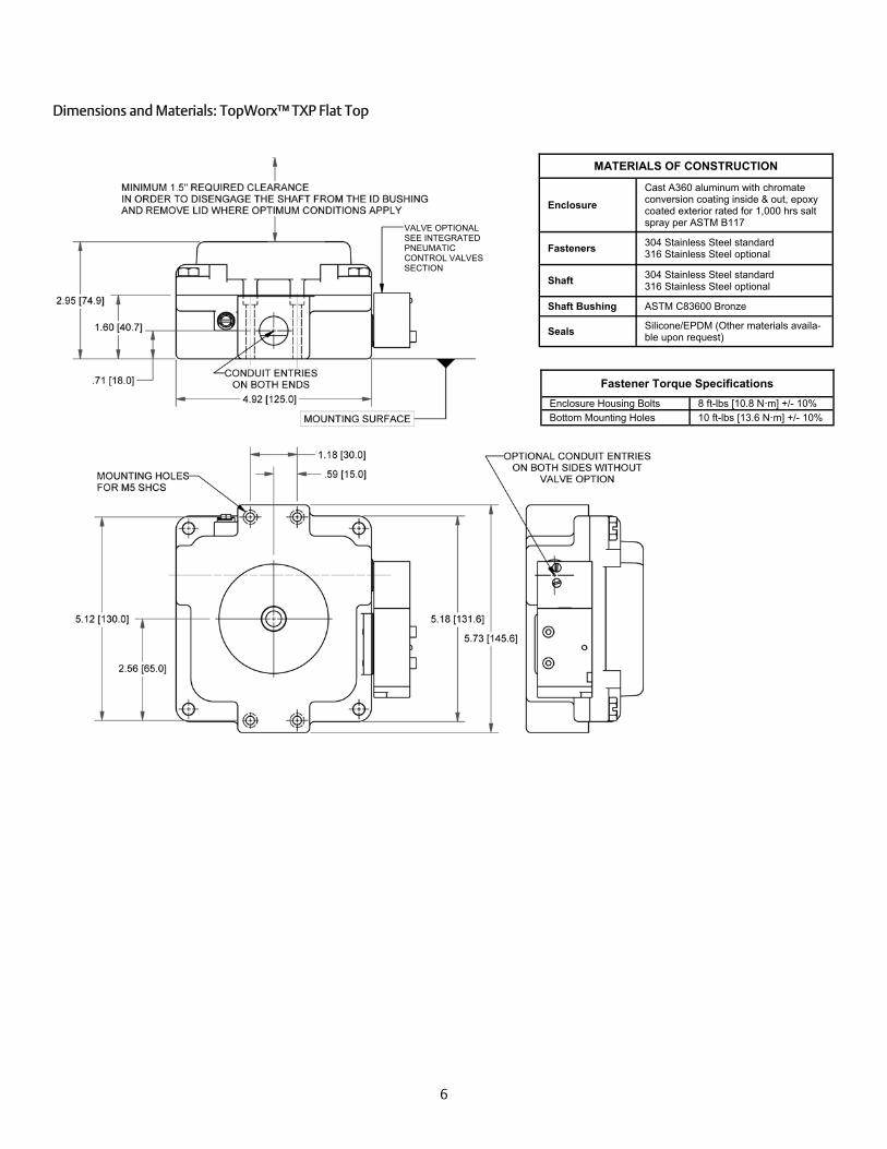
MATERIALS OF CONSTRUCTION
Enclosure Stainless steel. 316
Fasteners 304 Stainless Steel standard 316 Stainless Steel optional
Shaft 304 Stainless Steel standard 316 Stainless Steel optional
Shaft Bushing 316 Stainless Steel
Indicator Dome Same as TXP Dome
Seals Buna/EPDM (Other materials available upon request)
Fastener Torque Specifications
Enclosure Housing Bolts 8 ft-lbs [10.8 N·m] +/- 10%
Indicator Dome Screws 200 in-oz [i41 m N m] +/- 10%
Bottom Mounting Holes 10 ft-lbs [13.6 N·m] +/- 10%
Dimensions and Materials: TopWorx™ TXS
VALVE OPTIONAL SEE INTEGRATED PNEUMATIC CONTROL VALVES SECTION
8
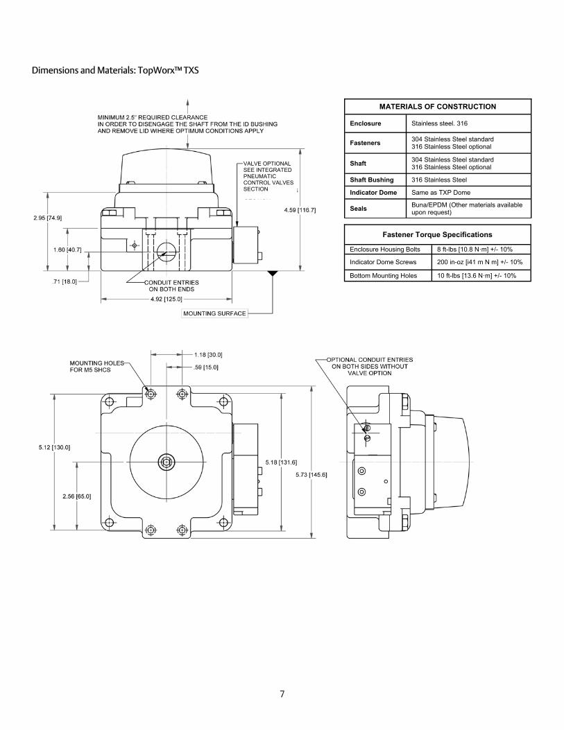
MATERIALS OF CONSTRUCTION
Enclosure Stainless steel. 316
Fasteners 304 Stainless Steel standard 316 Stainless Steel optional
Shaft 304 Stainless Steel standard 316 Stainless Steel optional
Shaft Bushing 316 Stainless Steel
Seals Silicone/EPDM (Other materials availa-ble upon request)
Dimensions and Materials: TopWorx™ TXS Flat Top
Fastener Torque Specifications
Enclosure Housing Bolts 8 ft-lbs [10.8 N·m] +/- 10% Bottom Mounting Holes 10 ft-lbs [13.6 N·m] +/- 10%
VALVE OPTIONAL SEE INTEGRATED PNEUMATIC CONTROL VALVES SECTION
9
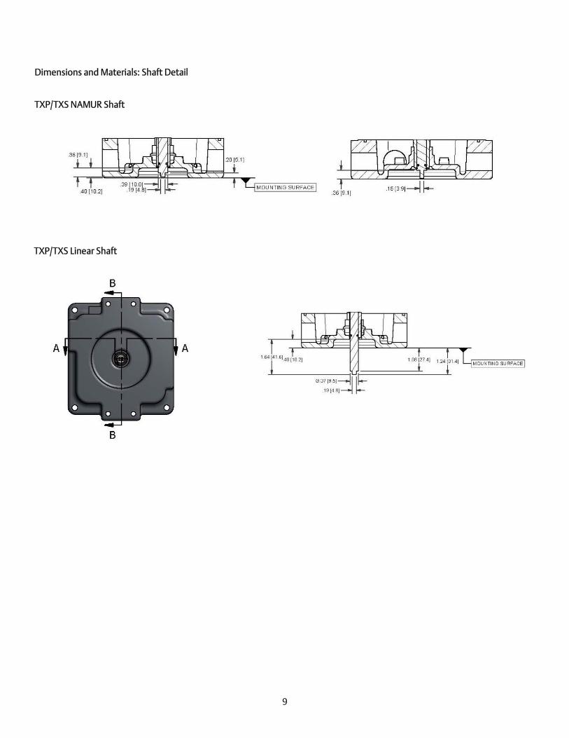
Dimensions and Materials: Shaft Detail
TXP/TXS NAMUR Shaft
TXP/TXS Linear Shaft

10
Sensors: Basic Function Each T-Series unit is equipped with 2 or 4 adjustable targets with a usable range between 45° and 90°. For normal acting applications the targets are color coded red for closed and green for open. The color code would be reversed for reverse acting units. After installing the unit on the actuator or valve assembly, the targets must be set.
Normal acting 1. Rotate the valve full CW to the closed position. 2. Twist the red target button(s) CW or CCW as required to engage the switch (refer to the specific switch section for testing
and confirmation information about your switch type). 3. Rotate the valve full CCW to the open position. 4. Twist the green target button(s) CW or CCW as required to engage the switch (refer to the specific switch section for test-
ing and confirmation information about your switch type).
Reverse acting 1. Rotate the valve full CW to the open position. 2. Twist the red target button(s) CW or CCW as required to engage the switch (refer to the specific switch section for test-
ing and confirmation information about your switch type). 3. Rotate the valve full CCW to the closed position. 4. Twist the green target button(s) CW or CCW as required to engage the switch (refer to the specific switch section for
testing and confirmation information about your switch type).
Normal-acting open position - or -
Reverse-acting closed position
Normal-acting closed position - or -
Reverse-acting open position
Setting Switches Unlock the green and red targets. Stroke the actuator open and closed to ensure there is no obstruction in it’s stroke. Once the actuator is at the desired position, twist the knob on the cam until the switch is made and lock the target. The red knob is for closed and the green knob is for open. For switching angles less than 45 degrees or more than 90 de-grees, consult factory for proper configuration.
OPEN
CLOSED

11
Switch Option L2: GO Switches
Wiring Diagram
Repeatability .002" (.05 mm)
Response Time 8 milliseconds
Differential 0.020 to 0.150 (0.5mm to 3.8mm)
Operating Temperature
-76° to 221°F (-60° to 105°C)
Contact Material Silver cadmium oxide, gold flashed
Forms SPDT, Form C
Electrical Ratings 4A@120VAC / 3A@24VDC
Target Material Ferrous metal
Sensing Range Approx. 1/10" (2.5 mm)
Sensing Range with Target Magnet
3 5/8" (92mm) (max)
GO Switches are dry contact, so they consume no power to operate and have no voltage drop or leakage current.
Also available from TopWorx™ : The TopWorx™ D-Series with DPDT, Stainless Steel GO Switches. Call Inside Sales or email [email protected] for more details
ES-00631-R2

12
Switch Option M2/M4 or K2/K4: SPDT Mechanical Switches When installing units with M or K switches a standard voltage ohm meter may be used to set the target cams by looking for continuity between the N/O and COMMON wires.
PRODUCT SPECIFICATIONS OPTION M
Switch Type Mechanical
Sealed No
Circuitry SPDT
Termination Quick Connect
Rating 10A@125VAC or 250VAC
Conforming to standards UL: 1054
Contact Resistance 15MΩmax. (initial)
Insulation Resistance 100MΩmin. (at 500V DC)
Switch Type Mechanical
Sealed No
Circuitry SPDT
Termination Quick Connect
Rating 10A@125VAC or 250VAC
Conforming to standards UL: 1054
OPTION K
Wiring Diagram
Switch Option T2: DPDT Mechanical Switches When installing units with T switches a standard voltage ohm meter may be used to set the target cams by looking for continuity between the N/O and COMMON wires.
PRODUCT SPECIFICATIONS Switch Type Mechanical Sealed No Circuitry DPDT Termination Quick Connect Rating 8A 125V AC or 250V AC Conforming to standards UL recognized and CSA certified, meets
MIL-S-8805 Contact Silver Terminals End Solder
Wiring Diagram

13
Switch Options P2 or R2/R4: SPDT Reed Proximity Switches When installing units with P or R switches a standard voltage ohm meter may be used to set the target cams by looking for continuity between the N/O and COMMON wires.
PRODUCT SPECIFICATIONS
P Option
Switching Voltage VDC 120V Max
Carry Current 3 Amp Max
Power Rating 3 - 100 Watt
Contact Material Tungsten
R Option
Switching Voltage DC/AC 30V Max
Carry Current 0.5 Amp Max
Switching Current 0.2 Amp Max
Power Rating 3 Watt
Contact Material Rhodium
Wiring Diagrams (R2/P2)
ES-00626-R4
14
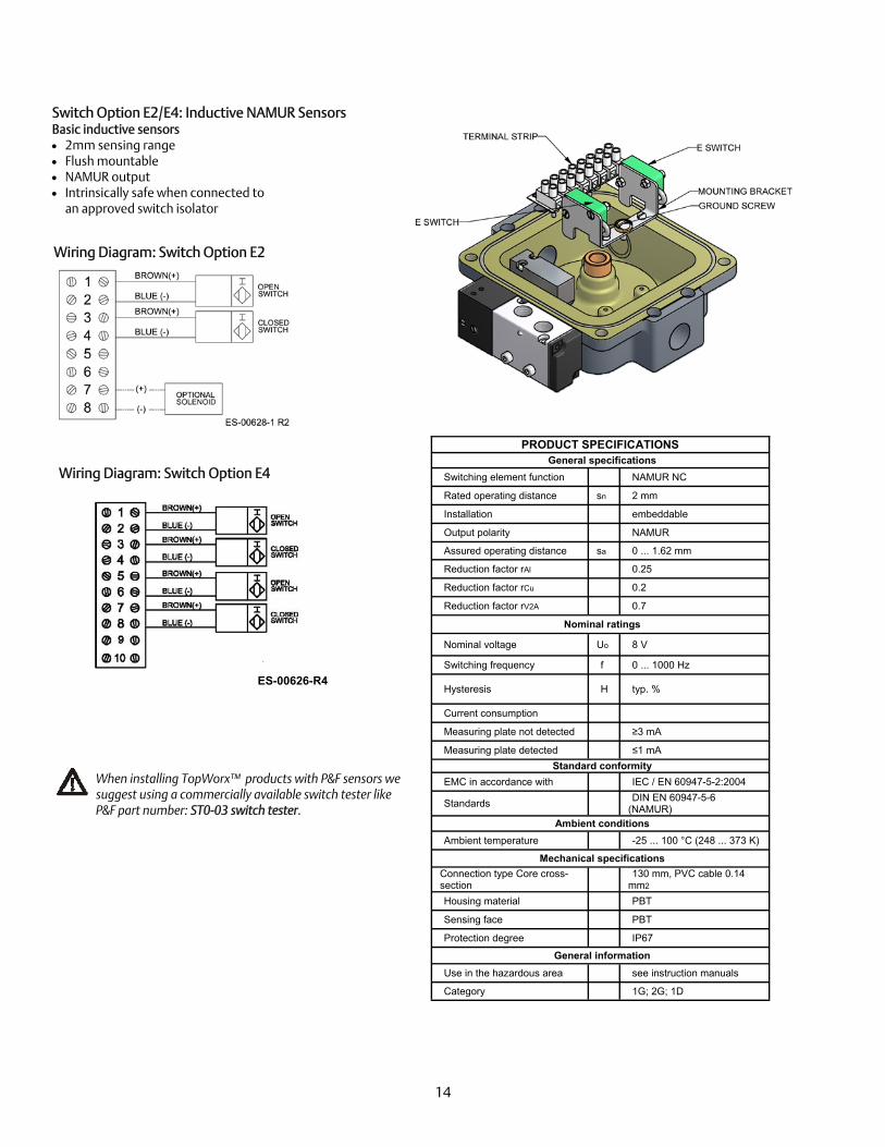
Switch Option E2/E4: Inductive NAMUR Sensors Basic inductive sensors 2mm sensing range Flush mountable NAMUR output Intrinsically safe when connected to
an approved switch isolator
PRODUCT SPECIFICATIONS General specifications
Switching element function NAMUR NC Rated operating distance sn 2 mm Installation embeddable Output polarity NAMUR Assured operating distance sa 0 ... 1.62 mm Reduction factor rAl 0.25 Reduction factor rCu 0.2 Reduction factor rV2A 0.7
Nominal ratings Nominal voltage Uo 8 V Switching frequency f 0 ... 1000 Hz
Hysteresis H typ. %
Current consumption Measuring plate not detected ≥3 mA Measuring plate detected ≤1 mA
Standard conformity EMC in accordance with IEC / EN 60947-5-2:2004 Standards DIN EN 60947-5-6
(NAMUR) Ambient conditions
Ambient temperature -25 ... 100 °C (248 ... 373 K) Mechanical specifications
Connection type Core cross-section 130 mm, PVC cable 0.14
mm2 Housing material PBT Sensing face PBT Protection degree IP67
General information Use in the hazardous area see instruction manuals Category 1G; 2G; 1D
Wiring Diagram: Switch Option E2
When installing TopWorx™ products with P&F sensors we suggest using a commercially available switch tester like P&F part number: ST0-03 switch tester.
Wiring Diagram: Switch Option E4
ES-00626-R4
15
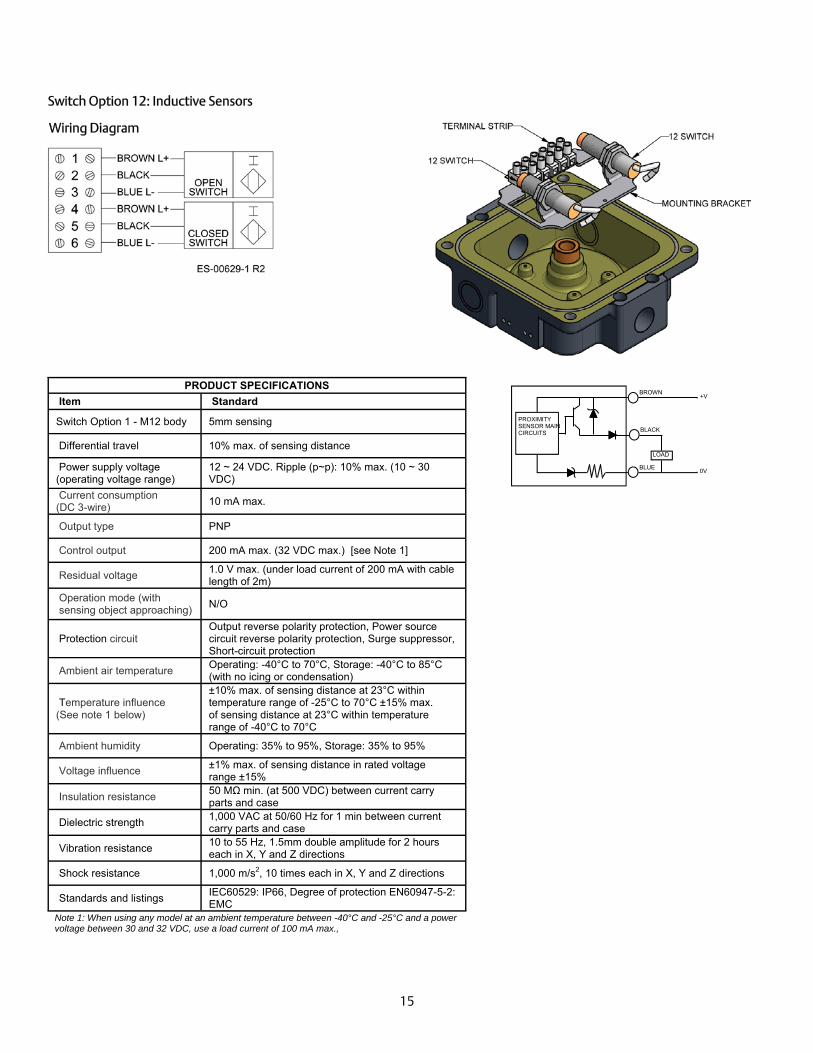
Switch Option 12: Inductive Sensors
Item Standard
Switch Option 1 - M12 body 5mm sensing
Differential travel 10% max. of sensing distance
Power supply voltage (operating voltage range)
12 ~ 24 VDC. Ripple (p~p): 10% max. (10 ~ 30 VDC)
Current consumption (DC 3-wire)
10 mA max.
Output type PNP
Control output 200 mA max. (32 VDC max.) [see Note 1]
Residual voltage 1.0 V max. (under load current of 200 mA with cable length of 2m)
Operation mode (with sensing object approaching)
N/O
Protection circuit Output reverse polarity protection, Power source circuit reverse polarity protection, Surge suppressor, Short-circuit protection
Ambient air temperature Operating: -40°C to 70°C, Storage: -40°C to 85°C (with no icing or condensation)
Temperature influence (See note 1 below)
±10% max. of sensing distance at 23°C within temperature range of -25°C to 70°C ±15% max. of sensing distance at 23°C within temperature range of -40°C to 70°C
Ambient humidity Operating: 35% to 95%, Storage: 35% to 95%
Voltage influence ±1% max. of sensing distance in rated voltage range ±15%
Insulation resistance 50 MΩ min. (at 500 VDC) between current carry parts and case
Dielectric strength 1,000 VAC at 50/60 Hz for 1 min between current carry parts and case
Vibration resistance 10 to 55 Hz, 1.5mm double amplitude for 2 hours each in X, Y and Z directions
Shock resistance 1,000 m/s2, 10 times each in X, Y and Z directions
Standards and listings IEC60529: IP66, Degree of protection EN60947-5-2: EMC
Note 1: When using any model at an ambient temperature between -40°C and -25°C and a power voltage between 30 and 32 VDC, use a load current of 100 mA max.,
PRODUCT SPECIFICATIONS
Wiring Diagram
PROXIMITY SENSOR MAIN CIRCUITS
LOAD
BROWN
BLACK
BLUE
+V
0V

16
Switch Option 42/44 or 52/54: Inductive Sensors
Switch Option 42/44 SUPPLY VOLTAGE 10-30 VDC
LOAD CURRENT (IL) 100 mA max.
LEAKAGE CURRENT (OFFSTATE) 0.05 mA typ., 0.1 μA at 25ºC
OUTPUT PNP normally open
VOLTAGE DROP AT IL (MAX.) ≤ 3 V
HYSTERESIS —
SHORT CIRCUIT AND OVERLOAD PROTECTION
Yes
REVERSE POLARITY Yes
FACE MATERIAL PBT
STANDARDS EN 60947-5-2
PROTECTION DEGREE IP67
AMBIENT TEMPERATURE -14 ºF to +158 ºF
(-25.6 ºC to +70 ºC)
SUPPLY VOLTAGE 5-60 VDC
LOAD CURRENT (IL) 100 mA max.
LEAKAGE CURRENT (OFFSTATE) 0.05 mA typ., 0.1 μA at 25ºC
OUTPUT 2 Wire DC normally open
VOLTAGE DROP AT IL (MAX.) ≤ 5 VDC
HYSTERESIS Typ. 0.2mm
SHORT CIRCUIT AND OVERLOAD PROTECTION
No
REVERSE POLARITY Yes
FACE MATERIAL Crastin
STANDARDS IEC / EN 60947-5-2:2004
ENVIRONMENTAL PROTECTION IP67
AMBIENT TEMPERATURE -14°F to +185°F
(-25.6 ºC to +85 ºC)
Switch Option 52/54
42 Wiring Diagram
52 Wiring Diagram
44 Wiring Diagram
54 Wiring Diagram
17
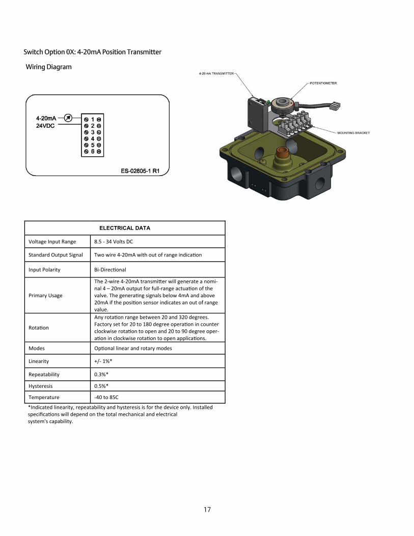
Switch Option 0X: 4-20mA Position Transmitter
ELECTRICAL DATA
Voltage Input Range 8.5 - 34 Volts DC
Standard Output Signal Two wire 4-20mA with out of range indica on
Input Polarity Bi-Direc onal
Primary Usage
The 2-wire 4-20mA transmi er will generate a nomi-nal 4 – 20mA output for full-range actua on of the valve. The genera ng signals below 4mA and above 20mA if the posi on sensor indicates an out of range value.
Rota on
Any rota on range between 20 and 320 degrees. Factory set for 20 to 180 degree opera on in counter clockwise rota on to open and 20 to 90 degree oper-a on in clockwise rota on to open applica ons.
Modes Op onal linear and rotary modes
Linearity +/- 1%*
Repeatability 0.3%*
Hysteresis 0.5%*
Temperature -40 to 85C *Indicated linearity, repeatability and hysteresis is for the device only. Installed specifica ons will depend on the total mechanical and electrical system's capability.
Wiring Diagram

18
Switch Option 0X: 4-20mA Position Transmitter
Calibration Flow Chart Apply power to device, LED on
Is button pressed and held for at least
0.5 seconds?
Is button released before 3 seconds?
Is button released before 5.5 seconds?
Is button released before 8 seconds?
Is button released?
Calibrate counterclockwise, device waits for 4ma set point, LED flashes code 3-1, rotary
Calibrate clockwise, device waits for 4ma set point, LED
flashes code 3-2, rotary
Calibrate counterclockwise, device waits for 4ma set point, LED flashes code 5-1, linear
Calibrate clockwise, device waits for 4ma set point, LED
flashes code 5-2, linear
User moves valve to 4ma position
Is button pressed and released?
Is the set point within required range?
Device waits for 20ma set point, LED flashes code 3-3
User moves valve to 20ma position
Is button pressed and released?
Is the set point within required range and has at least 20 degree of rotation
been detected?
Device stores set points, LED on
Is malfunction detected in stored set points?
Is the actual reading greater than maximum
4ma value?
Has greater than maximum allowed rotation occurred?
Has less than minimum allowed rotation occurred?
Wrong direction of rotation occurred, LED
flashes code 4-7
Start position is too high, LED flashes code 4-4
Start position is too low or in dead band,
LED flashes code 4-3
Less than allowed rotation has occurred, LED flashes code 4-5
Greater than allowed rotation has occurred, LED flashes code 4-6
Internal error, LED
YES
NO
YES
NO
YES
YES
YES
YES
NO
YES
NO
YES
NO
YES
YES
NO
YES
NO
YES
NO
NO
NO
YES
NO NO
Operation of the 4-20mA Current Position Transmitter During run mode, the 4-20mA position transmitter will output 4-20mA for valve positions between and including the set points. In rotary mode, the module has an optional over or under travel correction if the valve position exceeds the high or low set point by +/-3%. In other words, the output will be 4mA for +/-3% over and under travel on the low end and 20mA for +/-3% over and under travel on the high end. If the valve position exceeds 3% of over travel then values below 4mA or above 20mA will be output. The other user-selectable option is to calibrate the device without the over and under travel capability (Linear Mode.) See the calibration flow chart in this document for addi-tional information.
19
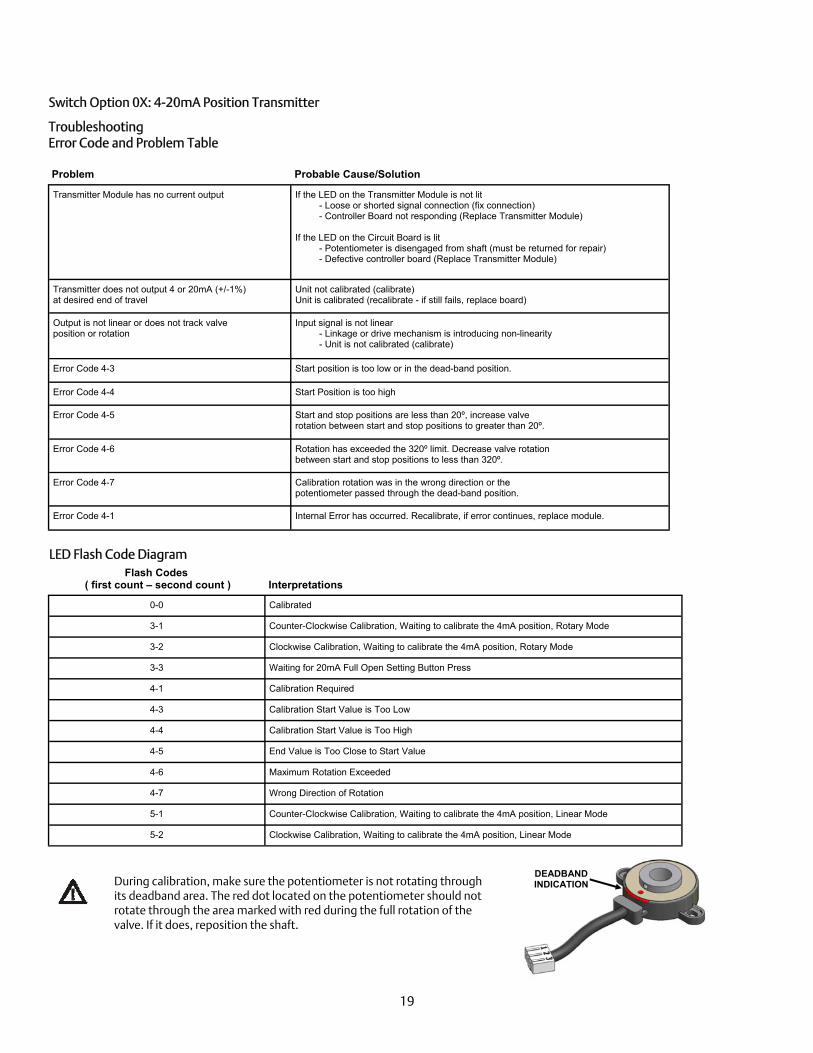
Switch Option 0X: 4-20mA Position Transmitter
Troubleshooting Error Code and Problem Table
Problem Probable Cause/Solution
Transmitter Module has no current output If the LED on the Transmitter Module is not lit - Loose or shorted signal connection (fix connection) - Controller Board not responding (Replace Transmitter Module)
If the LED on the Circuit Board is lit
- Potentiometer is disengaged from shaft (must be returned for repair) - Defective controller board (Replace Transmitter Module)
Transmitter does not output 4 or 20mA (+/-1%) at desired end of travel
Unit not calibrated (calibrate) Unit is calibrated (recalibrate - if still fails, replace board)
Output is not linear or does not track valve position or rotation
Input signal is not linear - Linkage or drive mechanism is introducing non-linearity - Unit is not calibrated (calibrate)
Error Code 4-3 Start position is too low or in the dead-band position.
Error Code 4-4 Start Position is too high
Error Code 4-5 Start and stop positions are less than 20º, increase valve rotation between start and stop positions to greater than 20º.
Error Code 4-6 Rotation has exceeded the 320º limit. Decrease valve rotation between start and stop positions to less than 320º.
Error Code 4-7 Calibration rotation was in the wrong direction or the potentiometer passed through the dead-band position.
Error Code 4-1 Internal Error has occurred. Recalibrate, if error continues, replace module.
LED Flash Code Diagram Flash Codes
( first count – second count ) Interpretations
0-0 Calibrated
3-1 Counter-Clockwise Calibration, Waiting to calibrate the 4mA position, Rotary Mode
3-2 Clockwise Calibration, Waiting to calibrate the 4mA position, Rotary Mode
3-3 Waiting for 20mA Full Open Setting Button Press
4-1 Calibration Required
4-3 Calibration Start Value is Too Low
4-4 Calibration Start Value is Too High
4-5 End Value is Too Close to Start Value
4-6 Maximum Rotation Exceeded
4-7 Wrong Direction of Rotation
5-1 Counter-Clockwise Calibration, Waiting to calibrate the 4mA position, Linear Mode
5-2 Clockwise Calibration, Waiting to calibrate the 4mA position, Linear Mode
DEADBAND INDICATION During calibration, make sure the potentiometer is not rotating through
its deadband area. The red dot located on the potentiometer should not rotate through the area marked with red during the full rotation of the valve. If it does, reposition the shaft.

20
Bus Option AS/AM: AS-i protocol
Openness 800+ products, 150 Vendors
Type of Network Sensor Bus
Physical Media 2-wire cable (flat or round)
Network Topology Bus, Ring, Tree, Star
Maximum Devices v2.0 31 nodes (or 248 I/O points) v2.1 62 nodes (or 434 I/O points) Maximum Distance Maximum Distance 100 meters Maximum Distance with repeaters (max. of 2 repeaters can be used)
300 meters
Communication Methods
Transmission Properties 5 mSec latency max. on fully loaded segment
Primary usage Master/Slave with cyclic polling Manchester Bit Encoding implemented via Alternating Pulse Modulation (APM)
v2.0 Discrete Signals
v2.1 Discrete Signals (supports 12 bit analog signals accessed over 5 cycles)
Power & Communications on same pair Limited to 200mA per device power consumption Requires AS-i specific power supply on communications bus for de-coupling
Device Power Supply
Devices can be supplied from bus (<200mA) Additional power can be supplied by AS-i power bus cable having multiple power supplies
(required for higher power outputs) Supply shall be powered by a limited-voltage power supply
Wiring Types Round: Normal 2 wire cable. #16AWG (1.5mm) Flat: 2 wire flat AS-i cable (1.5mm conductors) Yellow for communications / Black for additional power
Grounding aspects Ungrounded communications bus
Shielding Unshielded wire
Terminators No terminators required
Device Addressing Automatic when connected one at a time to the segment or with Handheld Addressing Unit
Governing Body ATO (AS-i Trade Organization) Website www.as-interface.com
Data bit Bit Function Input Output
D0 Input I1 / Output O1 Closed limit Red Solenoid switch 1
D1 Input I2 / Output O2 Open Limit Green Solenoid switch 2
D2 Input I3 / Output O3 N/A Solenoid switch 3
D3 Input I4 Fault signal (optional) N/A
Parameter bit Bit Function Configuration Code
P0 not used Extended ID code 1 7 P1 not used IO code 7 P2 not used Extended ID code 2 E
P3 not used Parameter 8
Watchdog on ID code A
AS-I Bit-Settings
Wiring Diagram
MECHANICAL SWITCHES OR REED SWITCHES
ASI BOARD
MOUNTING BRACKET

21
Bus Option PB/PM: Profibus Protocol
Type of Network Device Bus Physical Media Twisted pair, fiber
Network Topology Bus, Ring, Star
Maximum Devices max. 126 stations on one bus (maximum of 244 bytes input and output data possible for each slave)
Maximum Distance
DP 93.75Kbps and less – 1200 meters 500Kbps – 400 meters 1.5Mbps – 200 meters 12Mbps – 100 meters
Max Distance with repeater (max. of 9 repeaters can be used) 9,500 meters with repeaters
Communication Methods Peer-to-peer, multicast or cyclic master-slave (uses token passing sequence) Primary usage Used for Discrete and Analog for PLC, Variable Speed Drives, Remote I/O communications
Power and Communications Power is supplied separately from communications bus (can be supplied on a parallel power bus)
Device Power Supply Devices are powered separately from communications bus. A 5A maximum fuse muse be placed in series with the input power terminals.
Wiring Types Shielded twisted pair #22 AWG Device Addressing Handheld/Software only
Governing Body PROFIBUS International (PI)
Web Site www.profibus.com
PB/PM Wiring Diagram
(Continued next page.)
MECHANICAL SWITCHES OR REED SWITCHES
ASI BOARD
MOUNTING BRACKET

22
Switch Option PB/PM: Profibus Protocol (Continued) Technical Data
Power requirements
PROFIDP 4I20 V1.2 24VDC +- 10% Max I = 530mA (solenoid/s activated) Idle I = 24mA
Profibus info
ID 09ED HEX
GSD file TWIS09ED.GSD
Transmission Speed 12Mbaud
Line Parameters Line Type A Line Type B
Impedance 135 to 165 100 to 130
Capacitance per unit length (pF / m) <30 <60
Loop resistance (/ km) 110 ---
Core Diameter (mm) 0.64 >0.53
Core cross section (mm2) >0.34 >0.22
Transmission rate (kBaud) 9.6 19.2 93.75 187.5 500 1200 1500
Line type A 1200 1200 1200 1000 400 200 100
Line type B 1200 1200 1200 600 200 - -
Recommended Line Lengths
Software Parameters
OUTPUT BYTE 1 Fail Closed Fail Open Dual Coil
BITS
7 n/a n/a n/a n/a
6 n/a n/a n/a n/a
5 n/a n/a n/a n/a
4 n/a n/a n/a n/a
3 n/a n/a n/a n/a
2 n/a n/a n/a n/a
1 Output 2 n/a n/a High Closed
0 Output 1 High Open High Closed High Open
Low Closed Low Open
INPUT BYTE 1
BITS
7 n/a n/a
6 n/a n/a
5 n/a n/a
4 n/a n/a
3 SPARE Input 4
2 SPARE Input 3
1 High Closed Input 2
0 High Open Input 1
Diagnostic BYTE 1
BITS
7 n/a
6 n/a
5 n/a
4 n/a
3 n/a
2 Hard Wired high
1 Hard Wired high
0 Hard Wired high
Profibus Board

23
Integrated Pneumatic Pilots The 15 mm pilot valve has been designed and developed by TopWorx™ as a logical evolution of the traditional product range manufactured for the pneumatic market. The 15 mm solenoid valve is designed for those applications, more and more common on the actual market, where besides high performances in terms of pressure and flow, minimum dimension, very low power consumption and high reliability even at high cycling rates are specified. All the 15mm pilot valves feature: Heat-resistant bobbin molded with 30%
glass-filled polyester (PBT) Class H 200°C copper wire according
to IEC 317-8 Encapsulation with specially designed,
high-quality, glass-filled polyamide (PA66) Stainless steel guiding tube Plunger and core made of magnetic
stainless steel specially designed for solenoid applications
Contact factory for technical pilot valve information
INTEGRATED
INTEGRATED
24
Maintenance No maintenance is required. The bearing's internal diameter should be checked after 1 million cycles for wear. Require dimension should be between 10.00 to 10.05mm. In the event of wear, return the unit to the manufacturer for replace-ment. Switch setting can be checked periodically. Aggressive substances: e.g. acidic liquids or gases that may attack metals or solvents that may affect polymeric materials. If the equipment is likely to come into contact with aggressive substances, then it is the responsibility of the user to take suitable precautions that prevent it from being adversely affected, thus ensuring that the type of protection provided by the equip-ment is not compromised. Suitable precautions: e.g. regular checks as part of routine inspec-tions or establishing from the material’s datasheets that it is resistant to specific chemicals. If in doubt, contact TopWorx™ for assistance. Area Classifications Explosion Proof Protection Method Explosion proof protection is accomplished by using long flange and bearing surfaces with small clearances that do not allow flames from explosions to escape the enclosure. In the event that the flange surface or bearing areas become damaged, the protec-tion method will fail and allow potentially explosive vapor to ignite. Gaps between flanged surfaces, once torqued, should not exceed .0015” [.038mm]. Intrinsically Safe Protection Method For installation parameters, refer to the product nameplate. Non-Incendive Protection Method Non incendive units are designed with circuitry in which any arc or thermal effect produced, under intended operating conditions of the equipment, is not capable of igniting the flammable gas, vapor or dust-air mixtures.
Spool Valve Specifications
Medium Dried, filtered air (40 micron)
Max Operating Pressure
100psi (0.7 MPa) (6.89Bar)
Min. Operating Pressure
30psi (0.21 MPa) (2.06Bar)
Ambient Temperature Range
Refer to Product Nameplate Marking
Flow Coefficient 1.0Cv
Protection Degree Type 4, 4X, IP67
Port Size 1/4" NPT or BSP for 1.0Cv valve
Valve Body Available in Hardcoat Anodized Aluminum TF061 or 304 Stainless Steel or 316 Stain-less Steel
Valve Seals Buna-N/EPDM
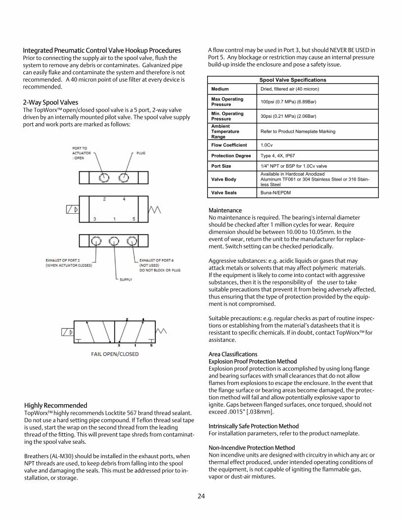
Integrated Pneumatic Control Valve Hookup Procedures Prior to connecting the supply air to the spool valve, flush the system to remove any debris or contaminates. Galvanized pipe can easily flake and contaminate the system and therefore is not recommended. A 40 micron point of use filter at every device is recommended. 2-Way Spool Valves The TopWorx™ open/closed spool valve is a 5 port, 2-way valve driven by an internally mounted pilot valve. The spool valve supply port and work ports are marked as follows:
A flow control may be used in Port 3, but should NEVER BE USED in Port 5. Any blockage or restriction may cause an internal pressure build-up inside the enclosure and pose a safety issue.
Highly Recommended TopWorx™ highly recommends Locktite 567 brand thread sealant. Do not use a hard setting pipe compound. If Teflon thread seal tape is used, start the wrap on the second thread from the leading thread of the fitting. This will prevent tape shreds from contaminat-ing the spool valve seals. Breathers (AL-M30) should be installed in the exhaust ports, when NPT threads are used, to keep debris from falling into the spool valve and damaging the seals. This must be addressed prior to in-stallation, or storage.
25
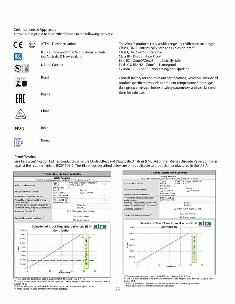
Certifications & Approvals TopWorx™ is proud to be certified for use in the following markets:
Proof Testing Sira Test & certification Ltd has conducted a Failure Mode, Effect and Diagnostic Analysis (FMEDA) of the T-Series Discrete Valve Controller against the requirements of IEC61508-2. The SIL ratings described below are only applicable to products manufactured in the U.S.A.
ATEX – European Union IEC – Europe and other World Areas, includ-ing Australia & New Zealand US and Canada Brazil Russia China India Korea
TopWorx™ products carry a wide range of certification markings: Class I, Div 1 – Intrinsically Safe and Explosion-proof Class I, Div 2 – Non-incendive Class III – Dust Ignition Proof Ex ia IIC – Zone0/Zone1 – Intrinsically Safe Ex d IIC & IIB+H2 – Zone1 – Flameproof Ex nAnC IIC – Zone2 – Non-arcing/Non-sparking Consult factory for copies of our certifications, which will include all product specifications such as ambient temperature ranges, gas/dust group coverage, intrinsic safety parameters and special condi-tions for safe use.
PESO

26
T-Series Safety Functions The safety functions of the T-Series Discrete Valve Controller are defined as:
To relieve pneumatic pressure to the spool valve by de-energizing the solenoid valve allowing the actuator to perform its safety function.
To admit pneumatic pressure to the spool valve by energizing the solenoid valve allowing the actuator to perform its safety func-tion.
The actuator and valve may be configured to fail safe in a normally open (N/O) or normally closed (N/C) configuration depending on the process under control. The T-Series Discrete Valve Controller requires an air supply in some form which must be assessed by the end user to ensure the required SIL is achieved. E.g. If the T-Series Discrete Valve Controller is configured with the safety function to admit pneumatic pressure to the actuator in order for it to revert to its fail safe state then a failure of the air supply will be dangerous failure (see Tables on pages 29 and 30). Hardware Functional Description The T-Series Discrete Valve Controller implements the safety functions as a sub-system as defined according to IEC 61508-2 clause 7.4.2.11 Note 1. Furthermore, with reference to IEC 61508-2 clause 7.4.4.1.2/3, the full assembly can be classified as a “Type A” sub-system. A com-plete functional block diagram of the T-Series Discrete Valve Controller can be shown in the Tables on pages 29 and 30. No fault (normal) conditions
a) Under normal operating conditions the T-Series Discrete Valve Controller will maintain the Normally Open (N/O actuator / valve in the closed position or the Normally Closed (N/C) actuator / valve in the open position.
b) The bus networking device may relay valve positional data to the operator during normal operating conditions but this device is not responsible for implementing the safety function.
Self diagnosed fault conditions The T-Series Discrete Valve Controller does not have any online fault diagnostics, however if the T-Series Discrete Valve Controller develops a fault which reverts the valve to its fail safe state then the sensor module will acknowledge this change in the valve position through the integrated shaft which is coupled to the valve. The bus networking device can then notify the operator of a valve position change without being requested. This kind of failure is a safe detectable failure (λ SD) and is considered as such in the FMEDA. If the T-Series Discrete Valve Controller develop a fault which latches the valve in its current, potentially dangerous, state then this form of failure will only be acknowl-edged during proof test, PVST or when a demand is placed on the element. The bus networking device can only notify the operator of no valve movement after failure event has occurred and therefore this kind of failure is a dangerous undetectable failure (λ DD) and is considered as such in the FMEDA. The utilization of the PVST by the T-Series Discrete Valve Controller will reveal any covert undetected dangerous failures and therefore in-crease the availability of the device. The use of PVST as a diagnostic tool will enable the following actions:
Detect the valve position Detect valve movement Measure the time to travel from open to partial stroke position
It should be realized that the electronics in the T-Series Discrete Valve Controller are performing positional feedback to the PLC and operator which is not considered online diagnostics. Diagnostic coverage is assessed in the FMEDA according to utilizing PVST to reveal covert unde-tected dangerous failures. This diagnostic coverage is only applicable at the point of PVST and not for normal operations.
Please visit our website to download a copy of the Sira Functional Safety Assessment Report for the T-Series Discrete Valve Controller at http://www.topworx.com/downloads/data.html.
27
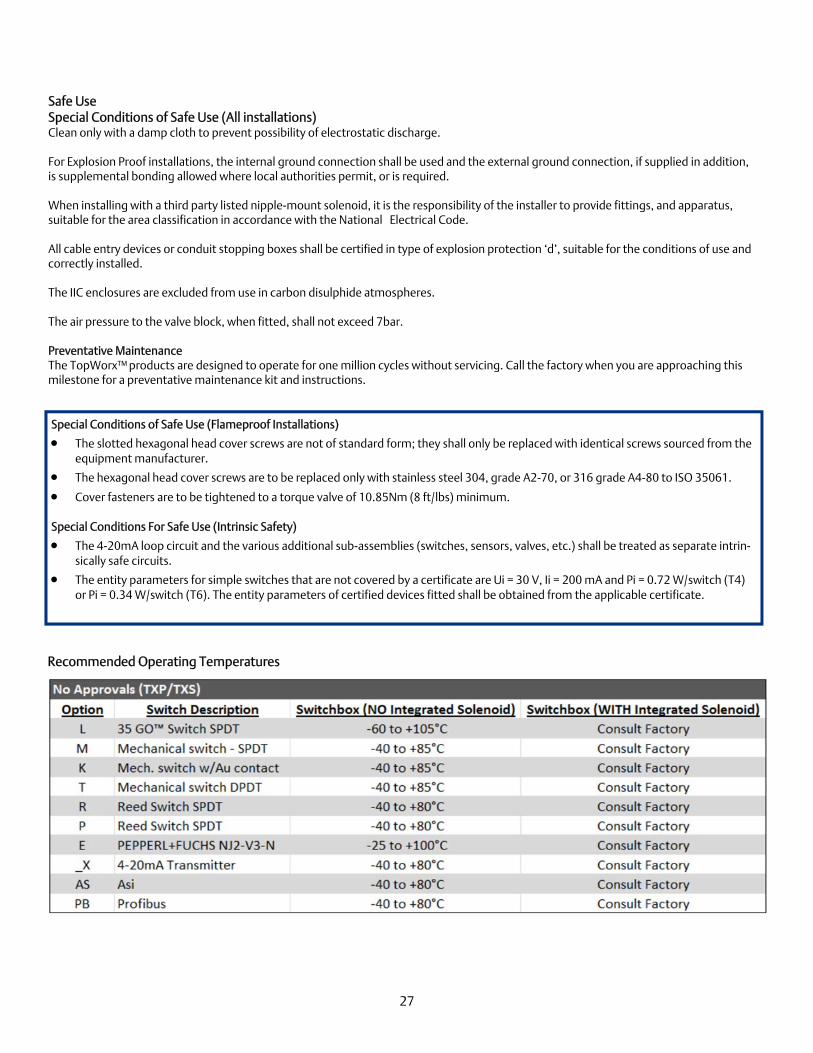
Recommended Operating Temperatures
Safe Use Special Conditions of Safe Use (All installations) Clean only with a damp cloth to prevent possibility of electrostatic discharge. For Explosion Proof installations, the internal ground connection shall be used and the external ground connection, if supplied in addition, is supplemental bonding allowed where local authorities permit, or is required. When installing with a third party listed nipple-mount solenoid, it is the responsibility of the installer to provide fittings, and apparatus, suitable for the area classification in accordance with the National Electrical Code. All cable entry devices or conduit stopping boxes shall be certified in type of explosion protection ‘d’, suitable for the conditions of use and correctly installed. The IIC enclosures are excluded from use in carbon disulphide atmospheres. The air pressure to the valve block, when fitted, shall not exceed 7bar. Preventative Maintenance The TopWorx™ products are designed to operate for one million cycles without servicing. Call the factory when you are approaching this milestone for a preventative maintenance kit and instructions.
Special Conditions of Safe Use (Flameproof Installations)
The slotted hexagonal head cover screws are not of standard form; they shall only be replaced with identical screws sourced from the equipment manufacturer.
The hexagonal head cover screws are to be replaced only with stainless steel 304, grade A2-70, or 316 grade A4-80 to ISO 35061.
Cover fasteners are to be tightened to a torque valve of 10.85Nm (8 ft/lbs) minimum. Special Conditions For Safe Use (Intrinsic Safety)
The 4-20mA loop circuit and the various additional sub-assemblies (switches, sensors, valves, etc.) shall be treated as separate intrin-sically safe circuits.
The entity parameters for simple switches that are not covered by a certificate are Ui = 30 V, Ii = 200 mA and Pi = 0.72 W/switch (T4) or Pi = 0.34 W/switch (T6). The entity parameters of certified devices fitted shall be obtained from the applicable certificate.

Visit www.topworx.com for comprehensive information on our company, capabilities, and products – including model numbers, data sheets, specifications, dimensions, and certifications. [email protected]
www.topworx.com
ES-01856-1 R15
GLOBAL SUPPORT OFFICES
The Emerson logo is a trademark and a service mark of Emerson Electric Co. ©2016 Emerson Electric Co. ©2014 - ©2016 TopWorx , All rights reserved.TopWorx™, and GO™Switch are trademarks of TopWorx ™. All other marks used in this document are the property of their respective owners. Information contained herein - including product specifications is subject to change without notice.
North America 3300 Fern Valley Road Louisville, Kentucky 40213 USA +1 502 969 8000 [email protected] Middle East P.O. Box 17033 Jebel Ali Free Zone Dubai 17033 United Arab Emirates +971 4 811 8283 [email protected]
Asia-Pacific Asia Pacific Pte Ltd - TopWorx c/o ASCO ASIA BLK4008, Ang Mo Kio Avenue 10 #04-17/22, Techplace 1 Singapore 569625 +65 6891 7550 [email protected] Africa 24 Angus Crescent Longmeadow Business Estate East Modderfontein Gauteng South Africa +27 011 451 3700 [email protected]
Europe Horsfield Way Bredbury Industrial Estate Stockport SK6 2SU United Kingdom +44 0161 406 5155 [email protected]
Related Documents