Technische Kundenunterlage Technical Customer Information Y 258 K01 024-000 Seite/Page 1 von/of 25 Datum/Date 16.03.2009 ©Alle Rechte bei Robert Bosch GmbH, auch für den Fall von Schutzrechtsanmeldungen. Jede Verfügungsbefugnis, wie Kopier- und Weitergaberecht, bei uns. ©Robert Bosch GmbH reserves all rights even in the event of industrial property.We reserve all rights of disposal such as copying and passing on to third parties Produkt / Product: Planar Wide Band Lambda Sensor with pumped O2 reference Typ / Type: LSU ADV for use in gasoline systems Bestellnummer / Part Number: 0 258 0.. ... Angebotszeichnung / Offer Drawing: A 258 ... ... Bemerkung / Comment: This document refers to the design type with protec- tion tube “TP3” for use in gasoline systems. Nr. Index Seite Page Änderung Revision Datum Date GS-SI/ENX9 GS-SI/ PJ-LSU4 GS-SI/ENX 1 - Erstausgabe / First Edition 16.03.09 gez. Schichlein gez. Albrecht gez. Stanglmeier

Welcome message from author
This document is posted to help you gain knowledge. Please leave a comment to let me know what you think about it! Share it to your friends and learn new things together.
Transcript

Technische Kundenunterlage
Technical Customer Information
Y 258 K01 024-000
Seite/Page 1 von/of 25 Datum/Date 16.03.2009
©Alle Rechte bei Robert Bosch GmbH, auch für den Fall von Schutzrechtsanmeldungen. Jede Verfügungsbefugnis, wie Kopier- und Weitergaberecht, bei uns.
©Robert Bosch GmbH reserves all rights even in the event of industrial property.We reserve all rights of disposal such as copying and passing on to third parties
Produkt / Product:
Planar Wide Band Lambda Sensor with pumped O2 reference
Typ / Type:
LSU ADV for use in gasoline systems
Bestellnummer / Part Number:
0 258 0.. ...
Angebotszeichnung / Offer Drawing:
A 258 ... ...
Bemerkung / Comment:
This document refers to the design type with protec-tion tube “TP3” for use in gasoline systems.
Nr. Index
Seite Page
Änderung Revision
Datum Date
GS-SI/ENX9 GS-SI/ PJ-LSU4
GS-SI/ENX
1
- Erstausgabe / First Edition 16.03.09 gez. Schichlein gez. Albrecht gez. Stanglmeier
Technische Kundenunterlage
Technical Customer Information
Y 258 K01 024-000
Seite/Page 2 von/of 25 Datum/Date 16.03.2009
©Alle Rechte bei Robert Bosch GmbH, auch für den Fall von Schutzrechtsanmeldungen. Jede Verfügungsbefugnis, wie Kopier- und Weitergaberecht, bei uns.
©Robert Bosch GmbH reserves all rights even in the event of industrial property.We reserve all rights of disposal such as copying and passing on to third parties
Contents 1. Characteristics 3
2. Application conditions 6
3. Test data (functional values) 9
4. Environmental test specification 14
5. Performing tests 18
6. Evaluation of field parts 19
7. Design types 19
8. Installation instructions 20
9. Operating instructions 23
10. Appendix 25
Reference Specifications Application guideline for gasoline systems Y 258 E00 018 Handling instruction Y 258 E00 000 Temperature measurement sensors Y 258 E00 006 Measuring procedure for temperature and thermo shock for gasoline systems Y 258 E00 007 LSU test bench and test method Y 258 E00 005 DLA-M Test Bench for response time measurement of LSU ADV lambda sensors Y 258 E00 027 This TKU is also valid for these documents.

Technische Kundenunterlage
Technical Customer Information
Y 258 K01 024-000
Seite/Page 3 von/of 25 Datum/Date 16.03.2009
©Alle Rechte bei Robert Bosch GmbH, auch für den Fall von Schutzrechtsanmeldungen. Jede Verfügungsbefugnis, wie Kopier- und Weitergaberecht, bei uns.
©Robert Bosch GmbH reserves all rights even in the event of industrial property.We reserve all rights of disposal such as copying and passing on to third parties
General The wide band lambda sensor LSU ADV is a planar ZrO2 dual cell limiting current sensor with an
integrated heater. It is used to measure the oxygen content and the λ-value of exhaust gases of com-bustion engines. The LSU ADV has been designed and tested only for use in the exhaust gas system of combustion engines.
This document refers to application in passenger cars with gasoline engine and operation with
gasoline as fuel. The wide band sensor LSU operates only in combination with a special LSU control unit (CJ125 ASIC).
The functional characteristics given in this document are only valid for operation with the CJ125 ac-cording to module specification and with recommended operational parameters. The sensor must not stay in the exhaust gas stream when it is not heated or when the control unit is switched off.
Remarks: Values marked with [N] in this document are nominal values or guide values. They depend
directly on other values which are specified with tolerances elsewhere in this document. 1. Characteristics 1.1 Electrical connection 5 pole 1.2 Sensor element
The heater supply voltage must be controlled, so that the temperature of the sensor is kept at the
operation point. The temperature is measured by measuring the internal resistance of the sensor’s Nernst cell Ri,N.
Nominal internal resistance of λ=1 Nernst cell for new sensors (operating and calibration point) Ri,N = 300 Ω [N] (measured with AC f = 3 kHz) Max. current load of λ=1 Nernst cell for new sensors. Continuous AC (f = 3 kHz) IN,max ≤ 80 µA for Ri,N-measurement
O2 reference pumping current (current source with max. 2.5V) • minimum necessary value for sensor function Ip,Ref,min ≥ 10 µA • nominal value continuous Ip,Ref = 20 µA • maximum value continuous Ip,Ref,max ≤ 25 µA • short time for 10 s in the ramp up phase
- recommended Ip,Ref = 20 µA - maximum Ip,Ref,max ≤ 75 µA
Max. pumping current into pump cell (IP)
• for rich gas signal (λ ≥ 0.65) Ip,max,rich ≥ -4 mA • for lean gas signal (air) Ip,max,lean ≤ 4 mA
Pumping current Ip must only be activated after the heater has been switched on and the sensor
element has reached a sufficient temperature (internal resistance of λ=1 Nernst cell Ri,N ≤ 2.3 kΩ). For correct operation, the reference pumping current must be activated as soon as possible after the
beginning of the heater profile. The voltage between RE-cable and IPN-cable must be < 1.8 V when the heater profile is activated (see section 9.5).
Note: if the reference pumping current deviates from its nominal value, the sensor accuracy might be
limited during this time.

Technische Kundenunterlage
Technical Customer Information
Y 258 K01 024-000
Seite/Page 4 von/of 25 Datum/Date 16.03.2009
©Alle Rechte bei Robert Bosch GmbH, auch für den Fall von Schutzrechtsanmeldungen. Jede Verfügungsbefugnis, wie Kopier- und Weitergaberecht, bei uns.
©Robert Bosch GmbH reserves all rights even in the event of industrial property.We reserve all rights of disposal such as copying and passing on to third parties
1.3 Isolation resistance (all measurements in static air, heater off)
• between housing and each heater- and sensor circuit connector pin at room temperature, measured with 800 V DC ≥ 10 MΩ
• between sensor signal circuit (IPN connected
to virtual mass VM, see section 9.5) and heater circuit at 650°C hexagon temperature, new and after aging acc. to section 4.1, measured with 12 V DC: ≥ 1 MΩ
• between sensor signal pin APE and housing
at 650°C hexagon temperature, new and after aging acc. to section 4.1, measured with 12V DC: ≥ 100 kΩ
Isolation resistance of wire harness see section 8.4 (installation instructions). 1.4 Coupling between heater and sensor signal Heating of the sensor with 9.4 W, potential between heater circuit and signal circuit with amplitude of
13 V and frequency of 20 Hz. Sensor signal evaluated with control unit over signal filter (R = 33 kΩ, C = 100 nF). Lab test is performed at room temperature, the specified value is also valid at hexagon tem-perature 650°C.
Sensor signal due to coupling: ∆Ip,meas ≤ 40 µA 1.5 Heater supply Nominal heater power at 7.5 V heater supply at thermal equilibrium in air PH,nom = 8.7 W [N] Nominal heater cold resistance at room temperature for new sensor, including cable and connector: RH,cold = 2.6 Ω ± 0.6 Ω Minimum heater cold resistance at -40°C: RH,cold,min = 1.6 Ω [N]

Technische Kundenunterlage
Technical Customer Information
Y 258 K01 024-000
Seite/Page 5 von/of 25 Datum/Date 16.03.2009
©Alle Rechte bei Robert Bosch GmbH, auch für den Fall von Schutzrechtsanmeldungen. Jede Verfügungsbefugnis, wie Kopier- und Weitergaberecht, bei uns.
©Robert Bosch GmbH reserves all rights even in the event of industrial property.We reserve all rights of disposal such as copying and passing on to third parties
1.6 Heating profile When the heater is switched on, heater power must be applied as follows:
t / s
maximumramp rate= 0,3 V /s
Heater power reducedduring condensationwater phase
max. 8 s
1,5 s
Effective heater voltageUH,eff
12 V
9 V
operation pointis reachedwhen Ri = Ri,N
0 5 10 15 20 t / s
1,8 ... 2 V
point in time is application specific
beginning ofheater profile
Heater power reducedat TCeramic = 640 °C, at the latest after 8 s
To rule out thermo shock damage of the sensor ceramic, the heater power must be limited during the condensation water phase - see measuring method Y 258 E00 007. When the ambient temperature is above 0 °C it is possible, under certain conditions, to begin the heater ramp before the end of the con-densation water phase has been reached. This operation mode must be tested and released in consul-tation with Bosch. The procedure is described in document Y 258 E00 007 (gasoline systems).
Heater voltage during condensation water phase: VH,eff = 1.8 V ... 2.0 V The following heating profile must be applied:
• heater voltage at t = 0 s until TCeramic = 640 °C is reached or at the latest at t = 8 s VH,eff ≤ 12 V
• heater voltage at TCeramic = 640 °C or at latest at t = 8 s for 1.5 s VH,eff ≤ 9 V
• ramp rate ∆VH,eff/∆t ≤ 0.3 V/s (t = 0: end of condensation water phase) If the ceramic temperature TCeramic is not controlled during the heat-up phase, the 12 V-phase must be
ended after 5 s. If UH,eff < 12 V the light-off time acc. to section 3.2 can not always be reached. Maximum permissible effective heater voltage VH,eff to reach the operating point
• short time ≤ 30 sec (200h cumulated time): VH,eff ≤ 12 V • continuous: VH,eff ≤ 11 V
Maximum system supply voltage VBatt,max VBatt,max ≤ 16.5 V
• short time voltage peak for 60 ms VBatt,max ≤ 28 V (10 times over lifetime, Tceramic ≥ 20°C)

Technische Kundenunterlage
Technical Customer Information
Y 258 K01 024-000
Seite/Page 6 von/of 25 Datum/Date 16.03.2009
©Alle Rechte bei Robert Bosch GmbH, auch für den Fall von Schutzrechtsanmeldungen. Jede Verfügungsbefugnis, wie Kopier- und Weitergaberecht, bei uns.
©Robert Bosch GmbH reserves all rights even in the event of industrial property.We reserve all rights of disposal such as copying and passing on to third parties
Minimum frequency of heater voltage control: fH ≥ 100 Hz Recommended frequency of heater voltage control: fH = 100 Hz Calculation of VH,eff with duty cycle (ED) VH,eff = (ED)1/2 * VBatt Remark: Heater duty cycles with fH ≥ 100 Hz have not been tested. Their use has to be clarified with
Bosch. The LSU may be used in 24 V grids only with voltage converters. 2. Application conditions 2.1 Temperature measurements Temperature measurements are performed with a special sensor equipped with NiCrNi thermocou-
ples. Sensor Type "MABCD" has measurement points at the upper side of the PTFE formed hose (Tup-
perhose), the cable grommet (Tgrommet), the hexagon of the sensor housing (Thexagon) and for the exhaust gas temperature (Texhaustgas).
For more information see description of temperature measurement sensors Y 258 E00 006 and
measurement method Y 258 E00 007. 2.2 Storage temperature (passive): -40°C ... +100°C Storage conditions see handling instruction Y 258 E00 000 2.3 Operating temperatures Exhaust gas: TExhaustgas ≤ 930°C Hexagon of the sensor housing: THexagon ≤ 650°C Cable grommet (PTFE formed hose)
• sensor side: TGrommet ≤ 250°C • cable side (upperhose crimp): TUpperhose ≤ 200°C
Cable and protective sleeve: TCable ≤ 250°C
(additional assembled parts such as clips or cable ties according to supplier spec or offer drawing)
Connector RB150-5-Pole (TCI 1 928 A01 15T-000): TConnector ≤ 140°C for connectors according to customer requirements according to specification of connector manufacturer 2.4 Maximum temperatures 2.4.1 (maximum 250 h accumulated over life time)
Exhaust gas: TExhaustgas ≤ 1030°C
Hexagon of the sensor housing: THexagon ≤ 700°C 2.4.2 (maximum 40 h accumulated over life time)
Cable grommet (PTFE formed hose)
• sensor side: TGrommet ≤ 280°C • cable side (upperhose crimp): TUpperhose ≤ 230°C

Technische Kundenunterlage
Technical Customer Information
Y 258 K01 024-000
Seite/Page 7 von/of 25 Datum/Date 16.03.2009
©Alle Rechte bei Robert Bosch GmbH, auch für den Fall von Schutzrechtsanmeldungen. Jede Verfügungsbefugnis, wie Kopier- und Weitergaberecht, bei uns.
©Robert Bosch GmbH reserves all rights even in the event of industrial property.We reserve all rights of disposal such as copying and passing on to third parties
Cable and protective sleeve: TCable ≤ 280°C (additional assembled parts such as clips or cable ties according to supplier spec or offer drawing)
Connector RB150-5-Pole (TCI 1 928 A01 15T-000): TConnector ≤ 150°C for connectors according to customer requirements according to specification of connector manufacturer Note: If the operating temperatures (section 2.3) are exceeded, the sensor accuracy might be limited
during this time. If the maximum gas temperature exceeds 930°C, or the hexagon temperature exceeds 650°C, the use
of a longer thread boss is recommended (see section 8). If the operating temperatures THexagon and TGrommet acc. to section 2.3 are exceeded simultaneously, it
has to be assured by appropriate measurements at the customer, that the temperature at the contact pads of the sensor element remains below 400°C.
2.5 Start-stop-operation The sensor is suitable for start-stop-operation. The sensor has to be heated during the entire stop phase. The pumping current, Ip, must be turned off
during the stop phase. The reference pumping current, Ip,ref, must stay on. If the sensor heating is turned off during the stop phase, this has to be tested and released in
coordination with Bosch. If condensation water is present in the exhaust gas system, the sensor has to be heated with reduced
heater power acc. to section 1.6. After the end of the condensation water phase, the sensor has to be heated up according to the heating profile in section 1.6.
2.6 Liquids in the exhaust gas system When condensation water is present at exhaust side (i.e. before dew point is reached), the heater
power of the sensor must be limited, see section 1.6. 2.7 Exhaust gas pressure (absolute pressure)
• continuous pgas ≤ 2.5 bar
Note: If the maximum continuous exhaust gas pressure is exceeded, the sensor accuracy might be limited during this time.
2.8 Permissible vibrations (measured at the sensor housing) Stochastic vibrations: ≤ 1000 m/s2 (measured at the peak level) Sinusoidal vibrations ≤ 300 m/s2
• vibration displacement: ≤ 0.3 mm

Technische Kundenunterlage
Technical Customer Information
Y 258 K01 024-000
Seite/Page 8 von/of 25 Datum/Date 16.03.2009
©Alle Rechte bei Robert Bosch GmbH, auch für den Fall von Schutzrechtsanmeldungen. Jede Verfügungsbefugnis, wie Kopier- und Weitergaberecht, bei uns.
©Robert Bosch GmbH reserves all rights even in the event of industrial property.We reserve all rights of disposal such as copying and passing on to third parties
2.9 Permissible fuel and fuel additives The LSU ADV has been designed for use with all commercially available gasoline and diesel fuels.
Testing has been performed with gasoline fuel in accordance with DIN EN228 for commercially avail-able unleaded fuel.
For a specific project, another fuel type can only be released after the specific fuel has been tested in
coordination with Bosch. 2.10 Permissible operating modes in gasoline systems
• intake-manifold fuel injection • gasoline direct injection at λ = 1
Another operating mode can only be released for a specific project after it has been tested in coordina-
tion with Bosch. 2.11 Oil consumption Permissible figures and data must be determined by the customer by adequate large-scale tests. 2.12 Life time The technical development of the sensor is aligned to a service life of 250,000 km and a maximum life
time of 15 years. Failure criterion is the non-compliance with the measurement data as mentioned un-der section 6.
The following conditions must be fulfilled in order to reach this service life:
• Application conditions acc. to sections 1 and 2. • Installation conditions acc. to section 8. • Checking of each application/installation location according to application guideline Y258 E00 018. • Usage of an RB approved sensor connector with gold plated sensor signal contacts.
The commercial warranty and liability is regulated in the conditions of delivery, independent of the above figures. The stated information above on lifetime for which the product has been construed, shall in no case be a guarantee regarding the condition or quality of the product.
2.13 Intended use If according to the supply agreement between the customer and Bosch, Bosch will be responsible for
delivered products being fit for the use or purpose intended and/or having a defined level of quality, such responsibilities are subject to the application of the product conforming to the agreed upon envi-ronment, installation and stress conditions, as such are referenced in this document. When the product during the Bosch release procedures has successfully met the testing specifications agreed to, or pro-vided by, the customer it is deemed to fully cover all requirements, if any, that the product be fit for the use or purpose intended and/or have a defined level of quality. The customer shall be responsible for the system application, which includes ensuring that the product application and all environmental, in-stallation and stress conditions to which the product will be exposed are covered by such testing. The customer shall be responsible for making sure that the product will not be exposed to conditions in ex-cess of those referenced in such testing specifications.

Technische Kundenunterlage
Technical Customer Information
Y 258 K01 024-000
Seite/Page 9 von/of 25 Datum/Date 16.03.2009
©Alle Rechte bei Robert Bosch GmbH, auch für den Fall von Schutzrechtsanmeldungen. Jede Verfügungsbefugnis, wie Kopier- und Weitergaberecht, bei uns.
©Robert Bosch GmbH reserves all rights even in the event of industrial property.We reserve all rights of disposal such as copying and passing on to third parties
3. Test data (functional values) Special hints for performing test bench measurements: The measurement is done with the sensor operated with an electronic control unit. The given toler-
ances are only validated for the lambda sensor. The heater power is closed-loop controlled while the measurement is done, so that the nominal sensor internal resistance is reached and maintained. The reference pumping current is a continuous 20 µA for all measurements. The signal, Ip,meas, is the cur-rent through a measuring resistance (see section 9) at pgas = 1013 hPa.
Due to the technical design of the gas test benches, these measurement data cannot be used for capability calculations.
3.1 Nominal characteristic line
For a synthetic gas (rich: 9% CO, 7% H2, 7% CO2, 1 % H2O in N2; lean: O2 in N2) in a laboratory measurement acc. to Y 258 E00 005, the following characteristic line is measured:
- 1,5
- 1,0
- 0,5
0,0
0,5
1,0
0,6 0,7 0,8 0,9 1,0 1,1 1,2 1,3 1,4 1,5 1,6 1,7 1,8 1,9 2,0 2,1 2,2 2,3 2,4 2,5
λ
Ip,meas / mA
lean test gas: O2 in N2
rich test gas: 9% CO, 7% H2, 7% CO2, 1% H2O in N2
- 0,5
0,0
0,5
1,0
1,5
0 5 10 15 20 25
Ip,meas / mA
calibration point
O2-concentration xO2 / %
test gas: O2 in N2
O2-Konz. xO2 [%] 0.00 3.00 6.00 8.29 12.0 20.95
λ-Wert 0.65 0.70 0.80 0.90 1.00 1.18 1.43 1.70 2.43 air
Ip,meas [mA] -1.38 -1.11 -0.65 -0.30 -0.02 0.17 0.36 0.52 0.77 1.40

Technische Kundenunterlage
Technical Customer Information
Y 258 K01 024-000
Seite/Page 10 von/of 25 Datum/Date 16.03.2009
©Alle Rechte bei Robert Bosch GmbH, auch für den Fall von Schutzrechtsanmeldungen. Jede Verfügungsbefugnis, wie Kopier- und Weitergaberecht, bei uns.
©Robert Bosch GmbH reserves all rights even in the event of industrial property.We reserve all rights of disposal such as copying and passing on to third parties
The λ-values for λ ≥ 1 in the above table can be calculated by
2
2
77.41
4/
/1
O
O
x
xCH
CH
⋅−
⋅+
+
=λ for an as-
sumed H/C-ratio of H/C = 2. For other H/C-ratios in a lean exhaust gas of combustion engines the corresponding λ-values can be calculated by the above formula.
3.2 Light-Off Time Measurement of the light-off time of the sensor in LSU test bench acc. to test method Y 258 E00 005: The light-off time is defined as the time between start of the heater ramp until the pumping current
Ip,meas stabilizes in a tolerance band of +/-10% of the final value in lean exhaust gas at λ = 1.7 and +/-25% in rich exhaust gas at λ = 0.8.
new after test bench run
Light-off time
≤ 5 s ≤ 5 s
Note: In the engine, the light-off time might differ, depending on installation and gas temperature
conditions. 3.3 Tolerances
Measurement in LSU test bench according to Y 258 E00 005:
new after test bench run
Pump. curr. Ip,meas [mA] at λ = 0.8 (*)
-0.652 ± 0.032 -0.652 ± 0.046 (*)
Pump. curr. Ip,meas [mA] at λ = 1.0
-0.018 ± 0.008 -0.018 ± 0.008
Pump. curr. Ip,meas [mA] at λ = 1.7
0.515 ± 0.022 0.515 ± 0.036 (*)
(*) equivalent to ∆Ip/Ip = ±7 %. The λ-value where the pumping current equals zero(Ip,meas = 0) is denoted as the characteristic value
"λstatic". The corresponding O2-concentration is:
0829.0)1()7.1(
)1()0(
,,
,,2
⋅=−=
=−==
λλ
λ
measpmeasp
measp
measpOII
IIx .
Therefore )0(77.41
1)0(3
1
,
,
2
2
=⋅−
+==
measpO
measpO
staticIx
Ix
λ .
For other λ-values and operating conditions the λ-tolerances can be calculated as follows:
For λ > 1 and small values of ∆Ip,meas/Ip,meas: ( )measp
measp
I
I
,
,1∆⋅−=∆ λλλ .
with Ip,meas: pumping current. Note: changes in the test gas composition, especially of the H2-concentra-tion, will have an influence
on the characteristics of the sensor. These influences are stronger in rich gas then under lean gas conditions.
Technische Kundenunterlage
Technical Customer Information
Y 258 K01 024-000
Seite/Page 11 von/of 25 Datum/Date 16.03.2009
©Alle Rechte bei Robert Bosch GmbH, auch für den Fall von Schutzrechtsanmeldungen. Jede Verfügungsbefugnis, wie Kopier- und Weitergaberecht, bei uns.
©Robert Bosch GmbH reserves all rights even in the event of industrial property.We reserve all rights of disposal such as copying and passing on to third parties
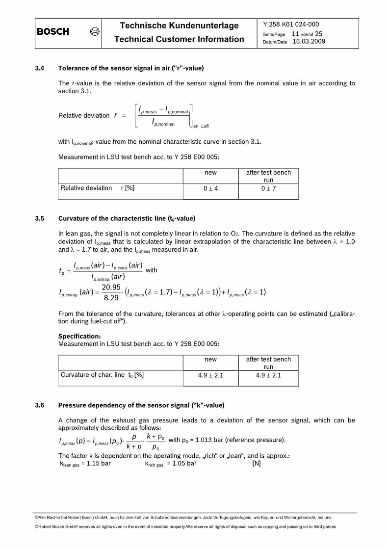
3.4 Tolerance of the sensor signal in air (“r”-value)
The r-value is the relative deviation of the sensor signal from the nominal value in air according to section 3.1.
Relative deviation
Luftanp
pmeasp
I
IIr
−=
nominal,
nominal,,
with Ip,nominal: value from the nominal characteristic curve in section 3.1. Measurement in LSU test bench acc. to Y 258 E00 005:
new after test bench run
Relative deviation r [%]
0 ± 4 0 ± 7
3.5 Curvature of the characteristic line (t0-value)
In lean gas, the signal is not completely linear in relation to O2. The curvature is defined as the relative deviation of Ip,meas that is calculated by linear extrapolation of the characteristic line between λ = 1.0 and λ = 1.7 to air, and the Ip,meas measured in air.
)(
)()(
.,
.,,0
airI
airIairIt
extrapp
extrapmeasp −= with
( ) )1()1()7.1(29.8
95.20)( ,,,., =+=−=⋅= λλλ measpmeaspmeaspextrapp IIIairI
From the tolerance of the curvature, tolerances at other λ-operating points can be estimated („calibra-
tion during fuel-cut off“). Specification: Measurement in LSU test bench acc. to Y 258 E00 005:
new after test bench run
Curvature of char. line t0 [%]
4.9 ± 2.1 4.9 ± 2.1
3.6 Pressure dependency of the sensor signal (“k”-value) A change of the exhaust gas pressure leads to a deviation of the sensor signal, which can be
approximately described as follows:
0
00,, )()(
p
pk
pk
ppIpI measpmeasp
+⋅
+⋅= with p0 = 1.013 bar (reference pressure).
The factor k is dependent on the operating mode, „rich“ or „lean“, and is approx.: klean gas = 1.15 bar krich gas = 1.05 bar [N]

Technische Kundenunterlage
Technical Customer Information
Y 258 K01 024-000
Seite/Page 12 von/of 25 Datum/Date 16.03.2009
©Alle Rechte bei Robert Bosch GmbH, auch für den Fall von Schutzrechtsanmeldungen. Jede Verfügungsbefugnis, wie Kopier- und Weitergaberecht, bei uns.
©Robert Bosch GmbH reserves all rights even in the event of industrial property.We reserve all rights of disposal such as copying and passing on to third parties
-30
-20
-10
0
10
20
30
40
50
0,4 0,6 0,8 1,0 1,2 1,4 1,6 1,8 2,0 2,2 2,4 2,6
lambda > 1
lambda < 1
absolute pressure / bar
∆Ip/Ip / % p0 = 1013 hPa
Specification:
Measurement in LSU test bench acc. to Y 258 E00 005:
new after test bench run
klean gas [bar] (measured at λ = 1.7; p = 4 bar)
1.15 ± 0.30 1.15 ± 0.30
3.7 Temperature dependency of the sensor signal and the internal resistance of the Nernst-cell Ri,N A temperature change of the sensor ceramic gives a deviation of the sensor output signal of approxi-
mately ∆IP,meas/IP,meas = 3% / 100°C [N]. The temperaure is known by measuring the internal resistance of the Nernst cell Ri,N and the following
curve:
10
100
1000
10000
600 700 800 900 1000
Operating point
Ri,N = 300 Ohm
Tceramic = 785°C
* measured at sensor side
Tceramic* / °C
Ri,N / Ω
Guide value [N] for operating point: • new: Ri,N = 300 Ω, Tceramic = 785 °C • after 3000 h test bench run: Ri,N = 300 Ω, Tceramic = 885 °C
Technische Kundenunterlage
Technical Customer Information
Y 258 K01 024-000
Seite/Page 13 von/of 25 Datum/Date 16.03.2009
©Alle Rechte bei Robert Bosch GmbH, auch für den Fall von Schutzrechtsanmeldungen. Jede Verfügungsbefugnis, wie Kopier- und Weitergaberecht, bei uns.
©Robert Bosch GmbH reserves all rights even in the event of industrial property.We reserve all rights of disposal such as copying and passing on to third parties
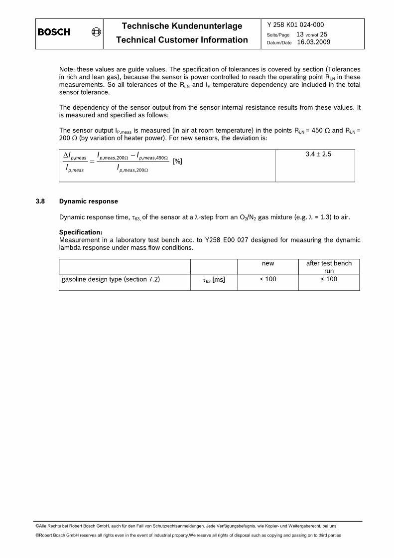
Note: these values are guide values. The specification of tolerances is covered by section (Tolerances in rich and lean gas), because the sensor is power-controlled to reach the operating point Ri,N in these measurements. So all tolerances of the Ri,N and IP temperature dependency are included in the total sensor tolerance.
The dependency of the sensor output from the sensor internal resistance results from these values. It
is measured and specified as follows: The sensor output IP,meas is measured (in air at room temperature) in the points Ri,N = 450 Ω and Ri,N =
200 Ω (by variation of heater power). For new sensors, the deviation is:
Ω
ΩΩ −=∆
200,,
450,,200,,
,
,
measp
measpmeasp
measp
measp
I
II
I
I [%]
3.4 ± 2.5
3.8 Dynamic response
Dynamic response time, τ63, of the sensor at a λ-step from an O2/N2 gas mixture (e.g. λ = 1.3) to air. Specification:
Measurement in a laboratory test bench acc. to Y258 E00 027 designed for measuring the dynamic lambda response under mass flow conditions.
new after test bench run
gasoline design type (section 7.2) τ63 [ms] ≤ 100
≤ 100

Technische Kundenunterlage
Technical Customer Information
Y 258 K01 024-000
Seite/Page 14 von/of 25 Datum/Date 16.03.2009
©Alle Rechte bei Robert Bosch GmbH, auch für den Fall von Schutzrechtsanmeldungen. Jede Verfügungsbefugnis, wie Kopier- und Weitergaberecht, bei uns.
©Robert Bosch GmbH reserves all rights even in the event of industrial property.We reserve all rights of disposal such as copying and passing on to third parties
4. Environmental test specification Each test must be carried out with new sensors. After completion of the tests, the sensors must be
within the tolerances as specified in sections 3.3 and 3.8 („after test bench run”), unless otherwise specified. During testing, the sensors are operated by a control unit, unless otherwise specified.
4.1 Engine endurance runs 4.1.1 Endurance run in gasoline engine
For measurements of functional values after endurance test the sensors have to be fitted into the
exhaust system of a λ=1 controlled gasoline engine. The sensors are operated with a control unit in this test (closed loop control of heater power).
Speed and load are changed in a 6-cycle program so that a temperature curve is reached in the sensor tip as per sketch. • Fuel: according to DIN EN228 for commercially available unleaded fuel. • Oil consumption ≤ 0.04 l/h. • Oil brand: multi-range oil viscosity 10W-40, API specification SF.
Compliance with the temperature limits as per section 2.3 must be ensured by adequate cooling. The exhaust gas temperature is set by varying engine speed and load. The temperature at the hexagon is limited by additional air cooling.
After the test, the functional values in sections 3.2, 3.3, 3.5, 3.6 and 3.8 (“after test bench run”) must
be fulfilled. Test time: 3000 h (500 h product audit)
T1 = exhaust gas
T2 = housing hexagon

Technische Kundenunterlage
Technical Customer Information
Y 258 K01 024-000
Seite/Page 15 von/of 25 Datum/Date 16.03.2009
©Alle Rechte bei Robert Bosch GmbH, auch für den Fall von Schutzrechtsanmeldungen. Jede Verfügungsbefugnis, wie Kopier- und Weitergaberecht, bei uns.
©Robert Bosch GmbH reserves all rights even in the event of industrial property.We reserve all rights of disposal such as copying and passing on to third parties
4.1.2 Test to silicon sensitivity (gasoline engine) Engine test run with additional silicon content in fuel (Oktamethylcyclotetrasiloxan). The sensors are
fitted in the exhaust pipe of a λ=1 controlled engine as in 4.1.1, but operated under the following condi-tions:
exhaust gas temperature: 400°C test time: 6 h Si-mass added over run time: 0.79 g 4.1.3 Test to sulfur sensitivity Engine test run with high sulfur content in fuel. The sensors are fitted in the exhaust pipe of a λ=1 controlled engine as in 4.1.1, but operated under
the following conditions: exhaust gas temperature: 200 °C (idle operation) test time: 500 h sulfur-mass added over life time: 188 g 4.1.4 Test to oil component sensitivity Engine test run with additional oil components in fuel. The sensors are fitted in the exhaust pipe of a λ=1 controlled engine as in section 4.1.1 but operated
under the following conditions: exhaust gas temperature (cycle): 30 min at 400 °C 30 min at 700 °C test time: 200 h fuel consumption in the test: 8.5 l/h Engine oil with high additives is mixed into the fuel. The whole amount of added oil additives is for the
complete test:
4.2 Further tests 4.2.1 Aging by operation in air
For measurement of the characteristic shift under continuous lean conditions, the sensors are oper-ated in calm air (room temperature). The sensors are operated with a control unit in this test (closed loop control of heater power). The signal output is monitored during the test.
test duration: 100 h test evaluation: Signal drift ≤ 7%
P [g] Ca [g] 20 26
Technische Kundenunterlage
Technical Customer Information
Y 258 K01 024-000
Seite/Page 16 von/of 25 Datum/Date 16.03.2009
©Alle Rechte bei Robert Bosch GmbH, auch für den Fall von Schutzrechtsanmeldungen. Jede Verfügungsbefugnis, wie Kopier- und Weitergaberecht, bei uns.
©Robert Bosch GmbH reserves all rights even in the event of industrial property.We reserve all rights of disposal such as copying and passing on to third parties
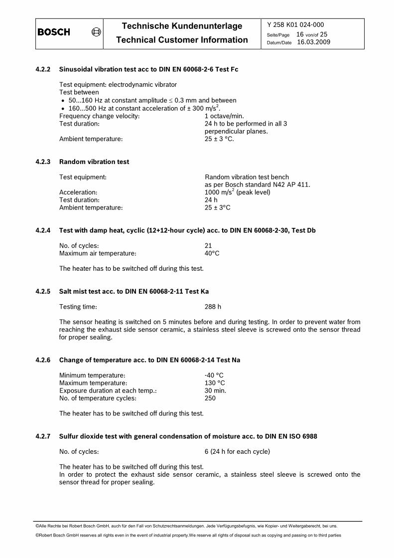
4.2.2 Sinusoidal vibration test acc to DIN EN 60068-2-6 Test Fc Test equipment: electrodynamic vibrator Test between
• 50...160 Hz at constant amplitude ≤ 0.3 mm and between • 160...500 Hz at constant acceleration of ± 300 m/s2.
Frequency change velocity: 1 octave/min. Test duration: 24 h to be performed in all 3 perpendicular planes. Ambient temperature: 25 ± 3 °C. 4.2.3 Random vibration test Test equipment: Random vibration test bench as per Bosch standard N42 AP 411. Acceleration: 1000 m/s2 (peak level) Test duration: 24 h Ambient temperature: 25 ± 3°C 4.2.4 Test with damp heat, cyclic (12+12-hour cycle) acc. to DIN EN 60068-2-30, Test Db No. of cycles: 21 Maximum air temperature: 40°C The heater has to be switched off during this test. 4.2.5 Salt mist test acc. to DIN EN 60068-2-11 Test Ka Testing time: 288 h The sensor heating is switched on 5 minutes before and during testing. In order to prevent water from
reaching the exhaust side sensor ceramic, a stainless steel sleeve is screwed onto the sensor thread for proper sealing.
4.2.6 Change of temperature acc. to DIN EN 60068-2-14 Test Na Minimum temperature: -40 °C Maximum temperature: 130 °C Exposure duration at each temp.: 30 min. No. of temperature cycles: 250 The heater has to be switched off during this test. 4.2.7 Sulfur dioxide test with general condensation of moisture acc. to DIN EN ISO 6988 No. of cycles: 6 (24 h for each cycle) The heater has to be switched off during this test. In order to protect the exhaust side sensor ceramic, a stainless steel sleeve is screwed onto the
sensor thread for proper sealing.
Technische Kundenunterlage
Technical Customer Information
Y 258 K01 024-000
Seite/Page 17 von/of 25 Datum/Date 16.03.2009
©Alle Rechte bei Robert Bosch GmbH, auch für den Fall von Schutzrechtsanmeldungen. Jede Verfügungsbefugnis, wie Kopier- und Weitergaberecht, bei uns.
©Robert Bosch GmbH reserves all rights even in the event of industrial property.We reserve all rights of disposal such as copying and passing on to third parties
4.2.8 Submergence test acc. to IEC 60529 * CEI 60529 IPx7 Water level 150 mm above sensor cable outlet. Test duration is 30 min. The connection system must
be out of the water during the test. The sensor is operated with a LSU control unit in this test, the sen-sor signal is monitored. In the test time the signal must be stable.
Test evaluation: the sensor signal in air must be Ip,meas ≤ 1.61 mA. 4.2.9 Wire pull test The mounted sensor has to withstand an axial force of 100 N applied to the connector for 1 min. 4.2.10 Fuel resistance test (FVP-test) The exhaust gas side of the sensor is exposed to Pentan vapor in a test chamber (pressure 100mbar).
The soak time is 2 h. After this the sensor is removed and then operated with a control unit. The output signal in ambient air is monitored for 120 min.
Test evaluation: the sensor signal in air must be Ip,meas ≤ 1.61 mA. 4.2.11 Fine leak test The gas leakage is measured from exhaust gas side with an air pressure of 4 bar (sensor not heated). The leakage rate must be smaller than 0.2 ml/min. 4.2.12 Drop test acc. to DIN EN 60068-2-32 test Ed proc. 1 The sensor is dropped onto a concrete floor from a height of 1m, one time.

Technische Kundenunterlage
Technical Customer Information
Y 258 K01 024-000
Seite/Page 18 von/of 25 Datum/Date 16.03.2009
©Alle Rechte bei Robert Bosch GmbH, auch für den Fall von Schutzrechtsanmeldungen. Jede Verfügungsbefugnis, wie Kopier- und Weitergaberecht, bei uns.
©Robert Bosch GmbH reserves all rights even in the event of industrial property.We reserve all rights of disposal such as copying and passing on to third parties
5. Performing tests Test procedure Section 100% test Lot release
test Product audit test
Design verification test (DV-Test)
Isolation resistance at room temperature (heater, sensor signal circuit and housing)
1.3 x
Isolation resistance hot (heater to sensor circuit and APE and housing
1.3 x
Coupling of heater duty cycle 1.4 x
Functional test in rich gas λ=0.8 x
Functional test in lean gas λ=1.7 (sensor calibration)
x x
Tolerances 3.3 x Light off time 3.2 x Curvature 3.5 x Pressure dependency 3.6 x Dynamic 3.8 x Engine endurance run gasoline, t = 500 h 4.1.1 x Engine endurance run gasoline, t = 3000 h 4.1.1 x Silicon sens. test (gasoline) 4.1.2 x Sulfur sensitivity test 4.1.3 x Oil component sens. test 4.1.4 x Operation in air 4.2.1 x Sinusoidal vibration test 4.2.2 x Random vibration test 4.2.3 x Test with damp heat 4.2.4 x Salt mist test 4.2.5 x Change of temperature 4.2.6 x Sulfur dioxide test 4.2.7 x Submergence test 4.2.8 x Wire pull test 4.2.9 x Fuel resistance test (FVP) 4.2.10 x Fine leak test 4.2.11 x Drop test 4.2.12 x
Note: All production lots are tested by lot release tests. Product audit tests are performed for monitoring the
product quality on a regular basis. Design validation tests are only performed with new sensor types in the design verification phase.

Technische Kundenunterlage
Technical Customer Information
Y 258 K01 024-000
Seite/Page 19 von/of 25 Datum/Date 16.03.2009
©Alle Rechte bei Robert Bosch GmbH, auch für den Fall von Schutzrechtsanmeldungen. Jede Verfügungsbefugnis, wie Kopier- und Weitergaberecht, bei uns.
©Robert Bosch GmbH reserves all rights even in the event of industrial property.We reserve all rights of disposal such as copying and passing on to third parties
6. Evaluation of field parts
When evaluating field returned parts, proper functionality is determined by testing the returned parts and obtaining the following characteristic data: • Functional values from sections 3.3 (tolerances “after test bench run”).
7. Design types The following types are available: 7.1 PTFE formed hose
• Longer PTFE hose at cable grommet for installations with critical temperature conditions in the sensor area.
• Shortened PTFE hose at cable grommet.
Note: the temperature resistance is the same for both types at the defined measuring points. 7.2 Protection tube
Design type with protection tube „TP3“ for use in gasoline systems

Technische Kundenunterlage
Technical Customer Information
Y 258 K01 024-000
Seite/Page 20 von/of 25 Datum/Date 16.03.2009
©Alle Rechte bei Robert Bosch GmbH, auch für den Fall von Schutzrechtsanmeldungen. Jede Verfügungsbefugnis, wie Kopier- und Weitergaberecht, bei uns.
©Robert Bosch GmbH reserves all rights even in the event of industrial property.We reserve all rights of disposal such as copying and passing on to third parties
8. Installation instructions The sensor installation point and the sensor functionality in the full system must be assured sufficiently
by the customer through appropriate vehicle tests under realistic conditions of use. 8.1 Installation in the exhaust system must be at a point guaranteeing representative exhaust gas
composition while also satisfying the specified temperature limits. Tested installation positions in gasoline applications: • after turbo charger • before catalyst
All other installation positions, e.g. before turbo charger, must be assured sufficiently in the respective application, in agreement with Bosch.
8.2 The lambda sensor must only be operated with a specially designed electronic control unit. The control
unit must only be activated after engine start. For switching on the sensor the heater power must al-ways be power controlled (e.g. duty cycled heater power). In the warm-up phase at engine start, the sensor is operated with reduced heater power as described in section 1.6. This is necessary to reduce thermal stress of the sensor element during cold starts due to high peak power in the first seconds.
The heater power must only be increased when the presence of condensed water in the exhaust gas system can be ruled out.
8.3 The sensor ceramic element is heated up quickly after heater start. Prior to heating up the ceramic
element, it must be guaranteed that there is no condensed water present. This could damage the hot ceramic element. To allow early light-off, the sensor installation location design must be selected in a way to minimize, or eliminate, condensed water on the exhaust gas side from contacting the sensor. If this is not possible by design measures, the start of the sensor heater must be delayed until demonstrably no more con-densation water appears.
Note: the method for application specific evaluation is described in document Y 258 E00 007 (for gaso-line application).
8.4 To ensure the necessary minimum reference pumping current, the isolation of the vehicle wire harness including all connections must be guaranteed. The minimum isolation resistance under all ambient conditions (temperature, humidity) over the whole vehicle life time must be ≥ 2 MΩ between all sensor signal pins.
8.5 Design measures
• Locate sensor as close to the engine as possible, respecting the maximum allowed temperature range.
• The exhaust pipe in front of the sensor must not contain any pockets, projections, protrusions, edges, flex-tubes etc. to avoid accumulation of condensed water. A downward slope of the pipe is recommended.
• Make sure that the front hole of the double protection tube does not point against exhaust gas stream.
• Attempt to achieve rapid heat-up of the exhaust pipes in the area in front of the sensor and also of the complete sensor thread boss area, to avoid developing condensed water.
• The sensor thread boss must be designed as shown in 8.12 to reach a rapid heat up of the sensor protection tube area. Make sure that the protection tube is completely in the exhaust gas stream.
8.6 System measures:
• Never switch on sensor heating or the control unit before engine start. • Delay of sensor heater start or power control of the sensor heater, e.g. as a function of engine and
ambient temperature (see section 1.6) The test method for evaluation is described in document Y 258 E00 007.

Technische Kundenunterlage
Technical Customer Information
Y 258 K01 024-000
Seite/Page 21 von/of 25 Datum/Date 16.03.2009
©Alle Rechte bei Robert Bosch GmbH, auch für den Fall von Schutzrechtsanmeldungen. Jede Verfügungsbefugnis, wie Kopier- und Weitergaberecht, bei uns.
©Robert Bosch GmbH reserves all rights even in the event of industrial property.We reserve all rights of disposal such as copying and passing on to third parties
0 . 1 ^ 0 . 2 R z 3 0
Æ 2 5M 1 8 x 1 . 5Æ 1 8 . 5
Æ 2 3 3mi
n. 10
.5( * m
in. 13
)
8.7 Installation angle must be inclined at least 10° towards horizontal (electrical connection upwards). This prevents the collection of liquids between sensor housing and sensor element during the cold start phase.
The angle w.r.t. the exhaust gas stream should be
90°. Other installation angles must be inspected and
tested for the specific project by the customer in coordination with Bosch.
For gasoline applications, (design type with
protection tube “TP3”) an angle of max. 90°+15° (gas entry hole to exhast gas stream) or 90°-30° resp. is allowed.
8.8 Underfloor installation of the sensor at a distance from the engine requires an additional check of the following points: • positioning of the sensor with respect to stone impact hazard • positioning and fixing of cable and connector with respect to mechanical damage, cable bending
stress and thermal stress.
8.9 Avoid excessive heating up of sensor cable grommet, particularly when the engine has been switched off after running under maximum load conditions.
8.10 The sensor should not be exposed to continuous, one-sided dripping of water, (e.g. by the air
conditioner condensed water drain). The thermal stress could lead to mechanical damage of the sen-sor.
8.11 The PTFE formed hose is part of the reference air volume of the sensor and must be kept sealed and undamaged. For installation, the minimum bending radius at the centerline of the hose must be 20 mm (for long PTFE hose) respectively 12 mm (for short hose). Keep the PTFE formed hose away from sharp edges and avoid contact/friction with frame/engine assembly.
The first fixing point for the cable to the car body should be 200 mm to 400 mm after the end of the PTFE formed hose, depending on movement of the exhaust system.
8.12 Recommended material for the thread boss in the exhaust pipe: Temperature resistant stainless steel, e. g. X 5 CrNi 18 10, DIN 17440 1.4301 or 1.4303 or
SAE 30304 or SAE 30305 (US standard) Thread boss dimensions should be as in sketch,
note that sensor thread must be covered com-pletely.
Recommendation(*): For hot applications
(THexagon>650°C or Tgas>930°C) the thread boss should be min. 13 mm to avoid overheating of the protection tube weld and to cool down the sensor hexagon.
If the protection tube welding is directly exposed to the exhaust gas (in case the installation angle is > 90° toward the exhaust gas stream) the 13mm thread must be used in order to cover the welding. The tolerance of the counter thread (6H) must be ensured after the thread boss is welded (with respect to welding distorsion).
Technische Kundenunterlage
Technical Customer Information
Y 258 K01 024-000
Seite/Page 22 von/of 25 Datum/Date 16.03.2009
©Alle Rechte bei Robert Bosch GmbH, auch für den Fall von Schutzrechtsanmeldungen. Jede Verfügungsbefugnis, wie Kopier- und Weitergaberecht, bei uns.
©Robert Bosch GmbH reserves all rights even in the event of industrial property.We reserve all rights of disposal such as copying and passing on to third parties
If the length is ≥16 mm (max. 22 mm permissible) the danger of thermo shock will be increased due to condensed water forming inside the protection tube. This must be covered separately by measure-ments described in Y 258 E00 007.
8.13 Tightening torque: 40 Nm ... 60 Nm, material characteristics and strength of the thread must be
appropriate. 8.14 Assembly with special high temperature resistant grease on the screw-in thread (e.g. Castrol Optimol
Paste MF or Bostic Never–Seez Regular Grade NS42B 2). 8.15 The use of cleaning/greasing fluids or evaporating solids at the sensor plug connection is not
permitted. The substances used must be free of organic ingredients acc. to ARCO-Test-no. > 36. Ex-ception: wetting of contact plugs with oil during punching with highly volatile punching oil Raziol CLF11.
8.16 The sensor and sensor connection must be covered when underbody sealant (wax, tar etc.), or spray
oil is applied to the vehicle. 8.17 The influence of contamination which enters the exhaust gas through the intake air or as a result of
fuel, oil, sealing materials etc., and thus reaches the λ-sensor, is application specific and must be de-termined by customer tests.
8.18 The sensor must not be exposed to strong mechanical shocks (e.g. while the sensor is installed).
Otherwise the sensor element may crack without visible damage to the sensor housing.

Technische Kundenunterlage
Technical Customer Information
Y 258 K01 024-000
Seite/Page 23 von/of 25 Datum/Date 16.03.2009
©Alle Rechte bei Robert Bosch GmbH, auch für den Fall von Schutzrechtsanmeldungen. Jede Verfügungsbefugnis, wie Kopier- und Weitergaberecht, bei uns.
©Robert Bosch GmbH reserves all rights even in the event of industrial property.We reserve all rights of disposal such as copying and passing on to third parties
9. Operating instructions 9.1 Conditions for connection and electrical operation of the sensor It must be assured, that when the sensor is operated, the connection to the control unit is not
disconnected during operation, or that the control unit diagnosis recognizes a failing connection. It is also not allowed, to disconnect or to connect the sensor to the control unit or ECU while the sensor
or control unit is being operated. Background: if the signal of the λ=1 cell is missing (e.g. connection failure), the internal control circuit
can not operate correctly, so that • an excessive pumping voltage with wrong polarization can destroy the pumping cell of the sensor • the sensor element can be destroyed by overheating, when the closed loop heater control is not
able to measure the ceramic temperature. The control unit may only be switched on after the sensor is connected completely. The sensor cables may never be connected in the wrong way or wrong polarity, otherwise the sensor
might be destroyed. The sensor must not stay in the exhaust gas stream when it is not heated or when the control unit is
switched off. 9.2 Use of LSU outside of the exhaust gas system The sensor can also be used outside an exhaust gas system, e.g. in air. When used in a stoichiometric (λ = 1) or rich gas (λ < 1), e.g. measurement gas in the test bench, it
must be assured, that enough O2 donators are available in the gas to allow the pumping cell to work. Otherwise the ZrO2 ceramic of the sensor can be reduced and the sensor destroyed.
The O2 donator may be free oxygen (non-equilibrium measurement gas), H2O or CO2. Guide values: H2O: ≥ 2 vol % CO2: ≥ 2 vol % 9.3 Electrical heating of the sensor The sensor heater may never be connected directly to battery voltage. It must always be controlled by
the LSU control unit or the vehicle ECU. Heating the sensor before the engine is started is not allowed. 9.4 Note for calculation of the sensor signal IP,meas when using a control unit Output voltage CJ125 : UCJ125 [V] = 1.5 + (Rmeas [Ohm]/1000*v) * IP,meas [mA] with Rmess as measurement resistance. The amplification factor, v, can be switched between v = 8 and
v = 17 in the CJ125. v = 17 (standard measuring range λ = 0.9 ... air) or v = 8 (measuring range λ = 0.7 ... air).

Technische Kundenunterlage
Technical Customer Information
Y 258 K01 024-000
Seite/Page 24 von/of 25 Datum/Date 16.03.2009
©Alle Rechte bei Robert Bosch GmbH, auch für den Fall von Schutzrechtsanmeldungen. Jede Verfügungsbefugnis, wie Kopier- und Weitergaberecht, bei uns.
©Robert Bosch GmbH reserves all rights even in the event of industrial property.We reserve all rights of disposal such as copying and passing on to third parties
9.5 Connection of LSU and control unit
UA
UH
Control unit with CJ125Sensor LSU ADV with wire harness and connector
O2, CO, HC, H2
+
measurement
resistance
reference
voltage
450 mV
Ri-Control
+
−
← Ipmeas
H−
H+
RE
APE IP
VM=2,5V
UN
−
−VCC
RV
IPN
20 µA
reference pump
current
+
grey
white
red
yellow
black
Technische Kundenunterlage
Technical Customer Information
Y 258 K01 024-000
Seite/Page 25 von/of 25 Datum/Date 16.03.2009
©Alle Rechte bei Robert Bosch GmbH, auch für den Fall von Schutzrechtsanmeldungen. Jede Verfügungsbefugnis, wie Kopier- und Weitergaberecht, bei uns.
©Robert Bosch GmbH reserves all rights even in the event of industrial property.We reserve all rights of disposal such as copying and passing on to third parties
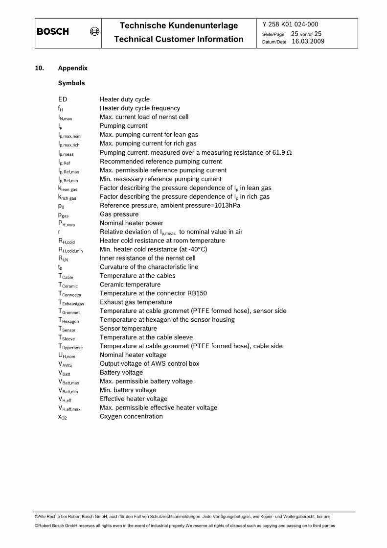
10. Appendix
Symbols
ED Heater duty cycle fH Heater duty cycle frequency IN,max Max. current load of nernst cell Ip Pumping current Ip,max,lean Max. pumping current for lean gas Ip,max,rich Max. pumping current for rich gas
Ip,meas Pumping current, measured over a measuring resistance of 61.9 Ω Ip,Ref Recommended reference pumping current Ip,Ref,max Max. permissible reference pumping current Ip,Ref,min Min. necessary reference pumping current klean gas Factor describing the pressure dependence of Ip in lean gas krich gas Factor describing the pressure dependence of Ip in rich gas p0 Reference pressure, ambient pressure=1013hPa pgas Gas pressure PH,nom Nominal heater power r Relative deviation of Ip,meas to nominal value in air RH,cold Heater cold resistance at room temperature RH,cold,min Min. heater cold resistance (at -40°C) Ri,N Inner resistance of the nernst cell t0 Curvature of the characteristic line TCable Temperature at the cables TCeramic Ceramic temperature TConnector Temperature at the connector RB150 TExhaustgas Exhaust gas temperature TGrommet Temperature at cable grommet (PTFE formed hose), sensor side THexagon Temperature at hexagon of the sensor housing TSensor Sensor temperature TSleeve Temperature at the cable sleeve TUpperhose Temperature at cable grommet (PTFE formed hose), cable side UH,nom Nominal heater voltage VAWS Output voltage of AWS control box VBatt Battery voltage VBatt,max Max. permissible battery voltage VBatt,min Min. battery voltage VH,eff Effective heater voltage VH,eff,max Max. permissible effective heater voltage xO2 Oxygen concentration
Related Documents