i WinTrac™ 5.X User Guide TK 54890-8-MS (Rev. 1, 04/11)

Welcome message from author
This document is posted to help you gain knowledge. Please leave a comment to let me know what you think about it! Share it to your friends and learn new things together.
Transcript

i
WinTrac™ 5.X User Guide TK 54890-8-MS (Rev. 1, 04/11)

Table of Contents
ii
Table of Contents
iii
Chapter 1 ......................................... .................................................................................................................... 1
Welcome to WinTrac Software ....................... ................................................................................................... 1
Main WinTrac Window ...................................................................................................................................... 1
Using the WinTrac Toolbar ............................................................................................................................... 2
Chapter 2 ......................................... .................................................................................................................... 4
Installing your WinTrac 5 Software ................ .................................................................................................. 4
Installing WinTrac 5 from CD ............................................................................................................................ 4
Installing WinTrac 5 on a Network .................................................................................................................... 4
Installing WinTrac 5 over an Existing Version ................................................................................................... 5
Customer Support ............................................................................................................................................. 5
Chapter 3 ......................................... .................................................................................................................... 6
Personalizing your WinTrac Software ............... ............................................................................................... 6
Changing WinTrac settings ............................................................................................................................... 6
WinTrac features............................................................................................................................................... 7
General .......................................................................................................................................................... 7
Communications ............................................................................................................................................ 7
Display Units .................................................................................................................................................. 8
Printer ............................................................................................................................................................ 8
Chapter 4 ......................................... .................................................................................................................... 9
Communicating with your Thermo King Units ......... ....................................................................................... 9
Searching for Thermo King Devices ................................................................................................................. 9
Changing Device Settings ............................................................................................................................... 11
Downloading Device Data ............................................................................................................................... 11
DRS Settings ................................................................................................................................................... 13
Accutrac Settings ............................................................................................................................................ 17
DMS Settings .................................................................................................................................................. 21
DAS Settings ................................................................................................................................................... 25
SR-2/SR-3, HMI Settings (ServiceWatch & CargoWatch) .............................................................................. 27
Multi-Temp Settings (mp-IV – TCI) ................................................................................................................. 34
MPD Settings .................................................................................................................................................. 37
MPA+, MPA Settings ....................................................................................................................................... 39
MPCR Settings ................................................................................................................................................ 41
TranScan Settings ........................................................................................................................................... 43
VPRS Settings................................................................................................................................................. 45
Support SR-3 platform – D000 (all basic support) .......................................................................................... 46
Support SR-3 platform – D005 ........................................................................................................................ 46
Conditions made for SR-3 (new feature support) ........................................................................................... 46
Initial WinTrac setup to access USB Flash Drive............................................................................................ 47
Configuration of USB Flash Drive using WinTrac ........................................................................................... 48
Upload and manage flash load files on USB Flash Drive using WinTrac ....................................................... 52
Upload and manage OptiSet Plus files on USB Flash Drive using WinTrac .................................................. 52
Translation of OptiSet Plus interchange XML file contents into Datapac commands in .osp file format. ....... 53
Chapter 5 ......................................... .................................................................................................................. 54
Managing your WinTrac Data files .................. ................................................................................................ 54
WinTrac File Management System ................................................................................................................. 54
Opening a WinTrac file ................................................................................................................................... 56
Creating new folders for WinTrac files ............................................................................................................ 57
Renaming a file or folder ................................................................................................................................. 57
Importing files into WinTrac 5 ......................................................................................................................... 58
File naming convention for imported files ....................................................................................................... 58
Moving a file or folder ...................................................................................................................................... 59
Deleting a file or folder .................................................................................................................................... 59
Table of Contents
iv
Chapter 6 ......................................... ................................................................................................................. 60
Viewing your Data Graphically ..................... .................................................................................................. 60
Main Slider ...................................................................................................................................................... 60
Zooming the Graph Window ........................................................................................................................... 61
Re-scaling a WinTrac graph ........................................................................................................................... 62
Time of Data ................................................................................................................................................... 63
Symbol Identification ....................................................................................................................................... 63
Viewing Data from Multi-Temperature Units ................................................................................................... 63
Viewing Data from DAS Loggers with attached controllers ............................................................................ 64
Panning through and expanding the Displayed Data...................................................................................... 64
Changing the Display Settings ........................................................................................................................ 64
Chapter 7 ......................................... ................................................................................................................. 65
Viewing your Data in Tabular Format ............... ............................................................................................. 65
To view the data in tabular format .................................................................................................................. 65
To filter the Tabular data ................................................................................................................................ 66
To Save the Tabular data ............................................................................................................................... 66
To Search the Tabular data ............................................................................................................................ 67
To Print the Tabular data ................................................................................................................................ 68
Tracing through the data................................................................................................................................. 69
Personalizing the Tabular Display .................................................................................................................. 69
Chapter 8 ......................................... ................................................................................................................. 70
Personalizing the Display ......................... ...................................................................................................... 70
To view the Display Settings ........................................................................................................................... 70
To view a sensor ............................................................................................................................................. 71
To change the color of a sensor ..................................................................................................................... 71
To rename a sensor label ............................................................................................................................... 71
To Define an Average Sensor ........................................................................................................................ 72
To Re-Scale a Graph ...................................................................................................................................... 72
To Re-Arrange the columns in the Tabular Data Window .............................................................................. 73
Chapter 9 ......................................... ................................................................................................................. 74
Advanced WinTrac Features ......................... .................................................................................................. 74
Exception Reporting ....................................................................................................................................... 74
Running a typical Exception Report ................................................................................................................ 74
Accessing the Tools Menu in WinTrac 5 ........................................................................................................ 76
User-Access level in WinTrac 5 software ....................................................................................................... 77
Flash loading your TK Device ......................................................................................................................... 78
Calibrating Sensors ........................................................................................................................................ 79
Ice-bath Calibration ..................................................................................................................................... 79
Graded-Sensor Calibration .......................................................................................................................... 80
Restarting your Thermo King Device .............................................................................................................. 81
Warm Restart .............................................................................................................................................. 81
Cold Restart................................................................................................................................................. 81
Setting up DAS Logging Modes ...................................................................................................................... 82
Using OptiSet Feature of TK Controllers ........................................................................................................ 83
Sending/Uploading OptiSet Configuration to a Controller ........................................................................... 83
Retrieving the current OptiSet Configuration from a Controller ................................................................... 83
Using OptiSet™ Plus Feature of TK Controllers ............................................................................................ 83
Sending/Uploading OptiSet Plus Configuration to a Controller ................................................................... 83
Retrieving the current OptiSet Configuration from a Controller ................................................................... 83
Using Service Modification feature on Thermo King Units ............................................................................. 84
Using pass-through mode on DAS ................................................................................................................. 84
Configure iBox ................................................................................................................................................ 85
iBox Third Party Communications .................................................................................................................. 86
Table of Contents
v
Chapter 10 ........................................ ................................................................................................................. 87
Troubleshooting your WinTrac Software ............. .......................................................................................... 87
Logging WinTrac Activity ................................................................................................................................. 87
Windows XP Service Pack 2 Database Issues ............................................................................................... 87
Unspecified Database Error ......................................................................................................................... 87
Installer Issues ................................................................................................................................................ 88
Failure Code -106: ....................................................................................................................................... 88
Microsoft Office applications do not run after installing WinTrac ................................................................. 88
Microsoft Office Installation Dialogs ................................................................................................................ 88
Printer Issues .................................................................................................................................................. 88
Not enough memory when printing to Postscript Printer.............................................................................. 88
Communications Issues .................................................................................................................................. 89
Failed to communicate with TK units ........................................................................................................... 89
Unable to open COM port ............................................................................................................................ 89
COM Port missing ........................................................................................................................................ 89
Disabling the Infra Red port on IBM Laptops ............................................................................................... 89
Computer shutting down with a Blue Screen ............................................................................................... 89
Graphics Issues .............................................................................................................................................. 89
Including a screenshot of WinTrac in a Word document ............................................................................. 89
Attaching WinTrac files to Notes and E-mails ................................................................................................. 90
Chapter 11 ........................................ ................................................................................................................. 91
License Agreement ................................. ......................................................................................................... 91

Chapter 1 Welcome to WinTrac Software
1
Chapter 1
Welcome to WinTrac Software
Welcome to WinTrac data logging software for Windows. WinTrac software is the easiest way to manage your data storage and display requirements for Thermo King data logging units. WinTrac 5 is compatible with Thermo King DAS, DAS-IV, DMS, DRS, AccuTRAC, TranScan, CargoWatch or ServiceWatch data loggers, Thermo King MPIV, MPV, MPVI, MPCR, MPD, MPA, MPA+, VPRS/DSR, TTMT, TSD, SR-2/SR-3 and Multi-Temp controllers equipped with data logging.
This manual introduces you to the main features of WinTrac software, showing you how to do the most common tasks quickly and easily. This manual also contains tips and hints on using WinTrac software as efficiently as possible.
In fact, WinTrac 5 makes the task of managing Thermo King data seem like child’s play!
This section gives you a quick overview on how to use WinTrac software, and introduces you to the main features of WinTrac. A guide to installing your WinTrac 5 software is contained at the end of this section.
Main WinTrac Window
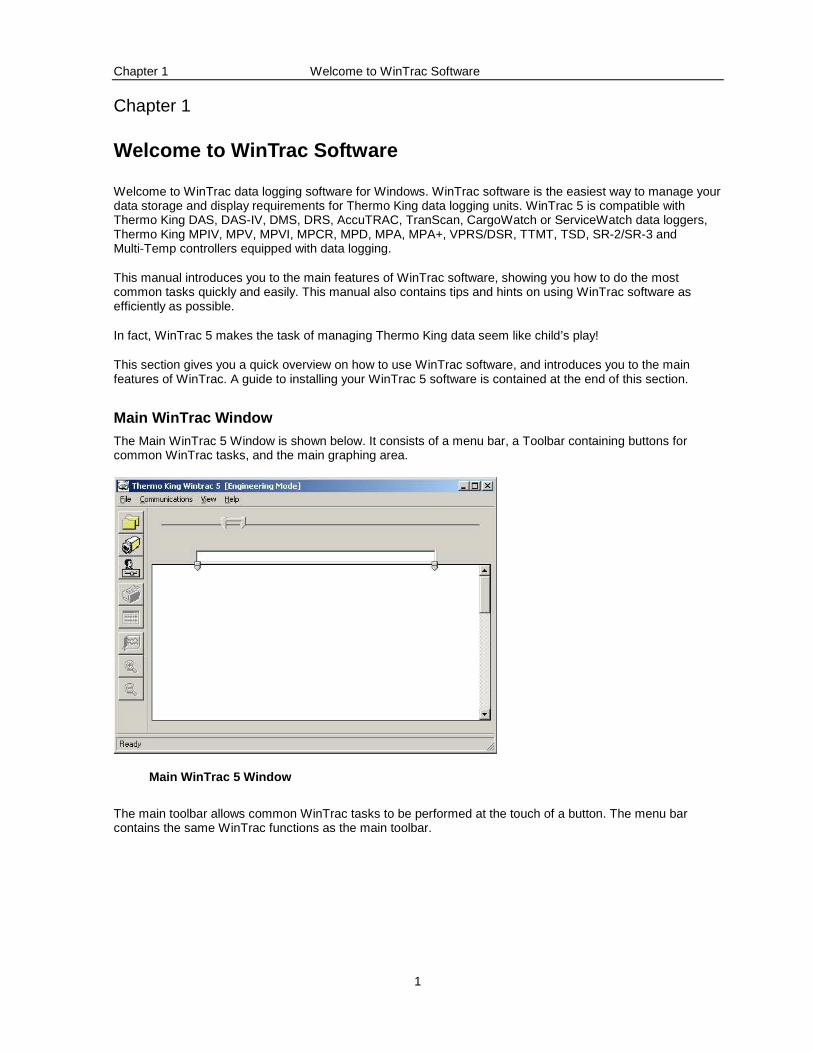
The Main WinTrac 5 Window is shown below. It consists of a menu bar, a Toolbar containing buttons for common WinTrac tasks, and the main graphing area.
Main WinTrac 5 Window
The main toolbar allows common WinTrac tasks to be performed at the touch of a button. The menu bar contains the same WinTrac functions as the main toolbar.
Chapter 1 Welcome to WinTrac Software
2
Using the WinTrac Toolbar
The WinTrac toolbar contains eight buttons; all associated with common WinTrac tasks. The use of each of the buttons is described below. Each of these tasks is described in detail later in this manual.
File Management button: Used to open existing WinTrac 5 data files, or import old files into WinTrac File Management System. WinTrac can open older WinTrac 4, 3, 2 and 1 files. This button also allows you to open and convert existing TracPac, PC-PAC, and MultiPac files for Thermo King units.
You can create separate folders for each of your units, organising by Trailer, Customer, etc. Files can be moved, copied, and deleted from the File Management Window.
Seek Device button: This button is used to communicate with your Thermo King Data loggers and Refrigeration units, and HP Palmtop PCs. WinTrac 5 currently supports DAS, DMS, DRS, AccuTRAC, CargoWatch, ServiceWatch and TranScan data loggers, MPIV, MPV, MPVI, MPCR and MPIV Multi-Temp controllers, MPA, MPA+, TTMT and MPD controllers.
WinTrac Settings button: Displays the WinTrac settings window. This window allows you to customise the WinTrac software for languages, temperature units, communications settings, etc. Your settings are retained the next time WinTrac software is used.
Graphics Print button: Obtains a graphic printout of currently selected data. The graphics print routine provides a hardcopy of the current data in the graphics window.
Tabular Data View button: Displays the currently selected graphical data in text form, arranging all the data in columns that can be moved, hidden, etc. The data in text form can be sent to your printer from the Tabular Data View, and also saved to an ASCII file for importing into other Windows applications.
Chapter 1 Welcome to WinTrac Software
3
Display Properties button: Launches the Display Properties Window. You can choose to display or hide sensors, change sensor labels and colours, etc. Your display settings are retained the next time WinTrac software is used.
Zoom-in button: Zooms into the currently selected region of data. You can select a region of data by using the “thumbs” at the top of the graphical display, or by simply clicking on the Graphical display and dragging until you have selected the region you want.
Zoom-out button: Zooms out to the previously selected view of your data. You can repeatedly click on the Zoom-out button until you have reached the original view when the file as opened.

Chapter 2 Installing your WinTrac 5 Software
4
Chapter 2
Installing your WinTrac 5 Software
This section describes how to install your WinTrac 5 software. WinTrac 5 is installed from the installation CD. You may also wish to install WinTrac 5 on a network. Each of these methods is described below.
Installing WinTrac 5 from CD
To install from CD, place your CD copy of WinTrac 5 into your CD-ROM drive and run D:\SETUP.EXE (where D: is your CD-ROM drive). Simply follow the instructions on-screen to install WinTrac 5 on your system.
Note: You should close down all running applications before installing WinTrac 5 software. This includes Microsoft Office Toolbar, which may be running in the background.
Installing WinTrac 5 on a Network
It is possible to install WinTrac 5 such that the database and data files are stored in a shared directory on a server.
To setup this configuration:
Install WinTrac 5 on each client PC that will need access to the WinTrac files.
Make a directory on the server which will contain the database and files (e.g. X:\WinTrac). Ensure that users have read, write and delete access to this directory.
Copy all files and subdirectories from the WinTrac\TemplateDB directory on a client PC to the shared directory.
On each client, configure WinTrac 5 to use the central database as described in Chapter 2.
Note that each user running WinTrac 5 will need full read, write, create and delete access to the shared directory on the server.
Chapter 2 Installing your WinTrac 5 Software
5
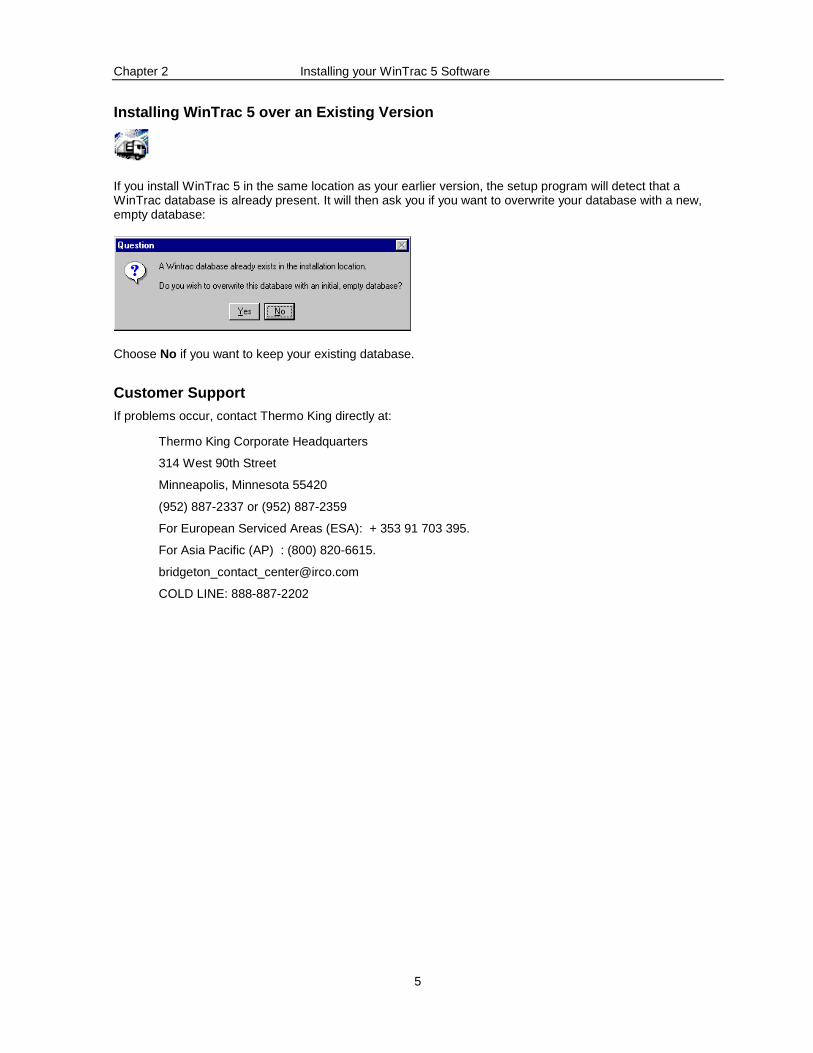
Installing WinTrac 5 over an Existing Version
If you install WinTrac 5 in the same location as your earlier version, the setup program will detect that a WinTrac database is already present. It will then ask you if you want to overwrite your database with a new, empty database:
Choose No if you want to keep your existing database.
Customer Support
If problems occur, contact Thermo King directly at:
Thermo King Corporate Headquarters
314 West 90th Street
Minneapolis, Minnesota 55420
(952) 887-2337 or (952) 887-2359
For European Serviced Areas (ESA): + 353 91 703 395.
For Asia Pacific (AP) : (800) 820-6615.
COLD LINE: 888-887-2202
Chapter 3 Personalizing your WinTrac Software
6
Chapter 3
Personalizing your WinTrac Software
WinTrac software contains a Settings Window which allows you to personalize your WinTrac software. You can choose the language of your choice; choose either Celsius or Fahrenheit units on all screens and printouts, etc.
Changing WinTrac settings
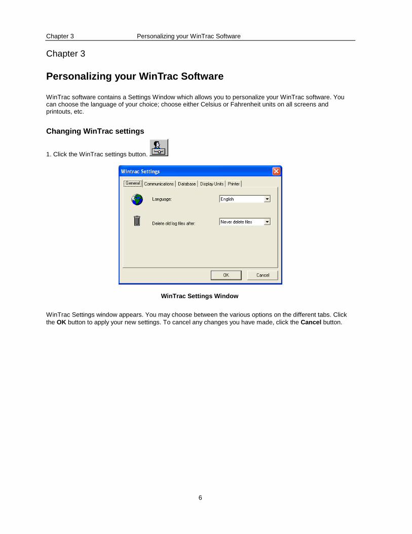
1. Click the WinTrac settings button.
WinTrac Settings Window
WinTrac Settings window appears. You may choose between the various options on the different tabs. Click the OK button to apply your new settings. To cancel any changes you have made, click the Cancel button.
Chapter 3 Personalizing your WinTrac Software
7
WinTrac features:
General
WinTrac software allows you to select a working language for the software. Choose from English, French, German, Italian, or Spanish. All WinTrac screens, messages and printouts will reflect the language of your choice.
WinTrac software keeps diagnostic log files as it works. You can have WinTrac automatically delete these after a few weeks or months in order to conserve space.
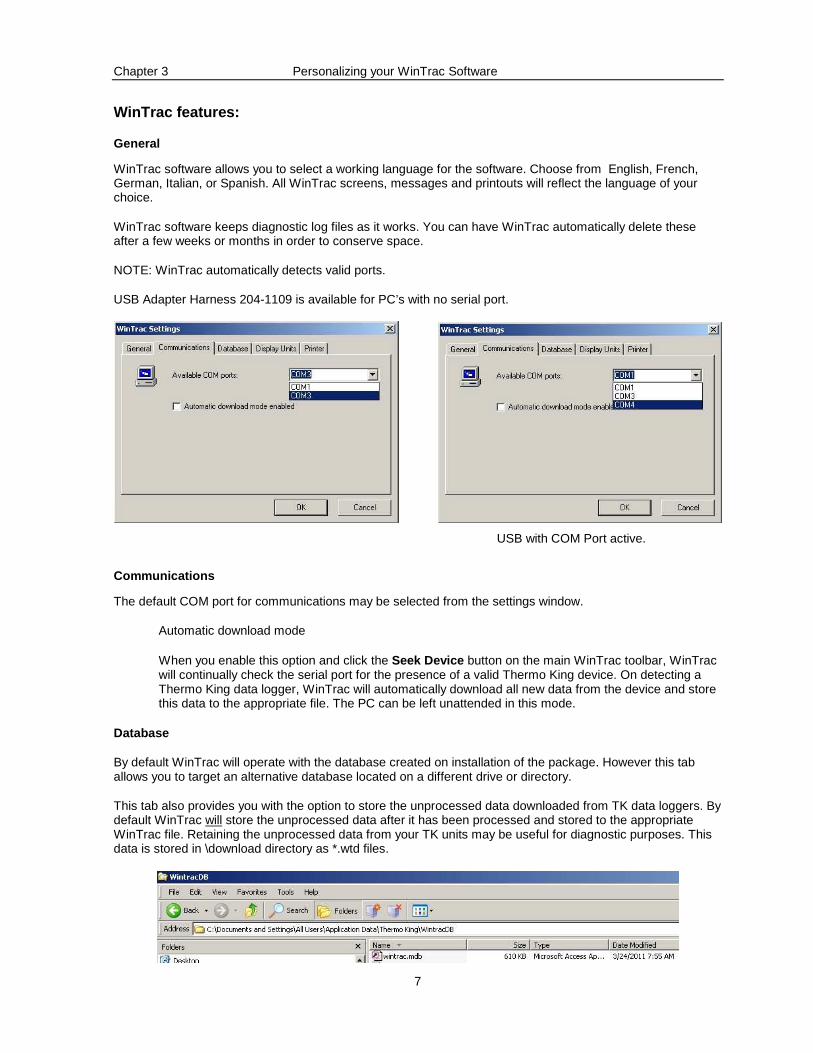
NOTE: WinTrac automatically detects valid ports.
USB Adapter Harness 204-1109 is available for PC’s with no serial port.
USB with COM Port active.
Communications
The default COM port for communications may be selected from the settings window.
Automatic download mode
When you enable this option and click the Seek Device button on the main WinTrac toolbar, WinTrac will continually check the serial port for the presence of a valid Thermo King device. On detecting a Thermo King data logger, WinTrac will automatically download all new data from the device and store this data to the appropriate file. The PC can be left unattended in this mode.
Database
By default WinTrac will operate with the database created on installation of the package. However this tab allows you to target an alternative database located on a different drive or directory.
This tab also provides you with the option to store the unprocessed data downloaded from TK data loggers. By default WinTrac will store the unprocessed data after it has been processed and stored to the appropriate WinTrac file. Retaining the unprocessed data from your TK units may be useful for diagnostic purposes. This data is stored in \download directory as *.wtd files.
Chapter 3 Personalizing your WinTrac Software
8
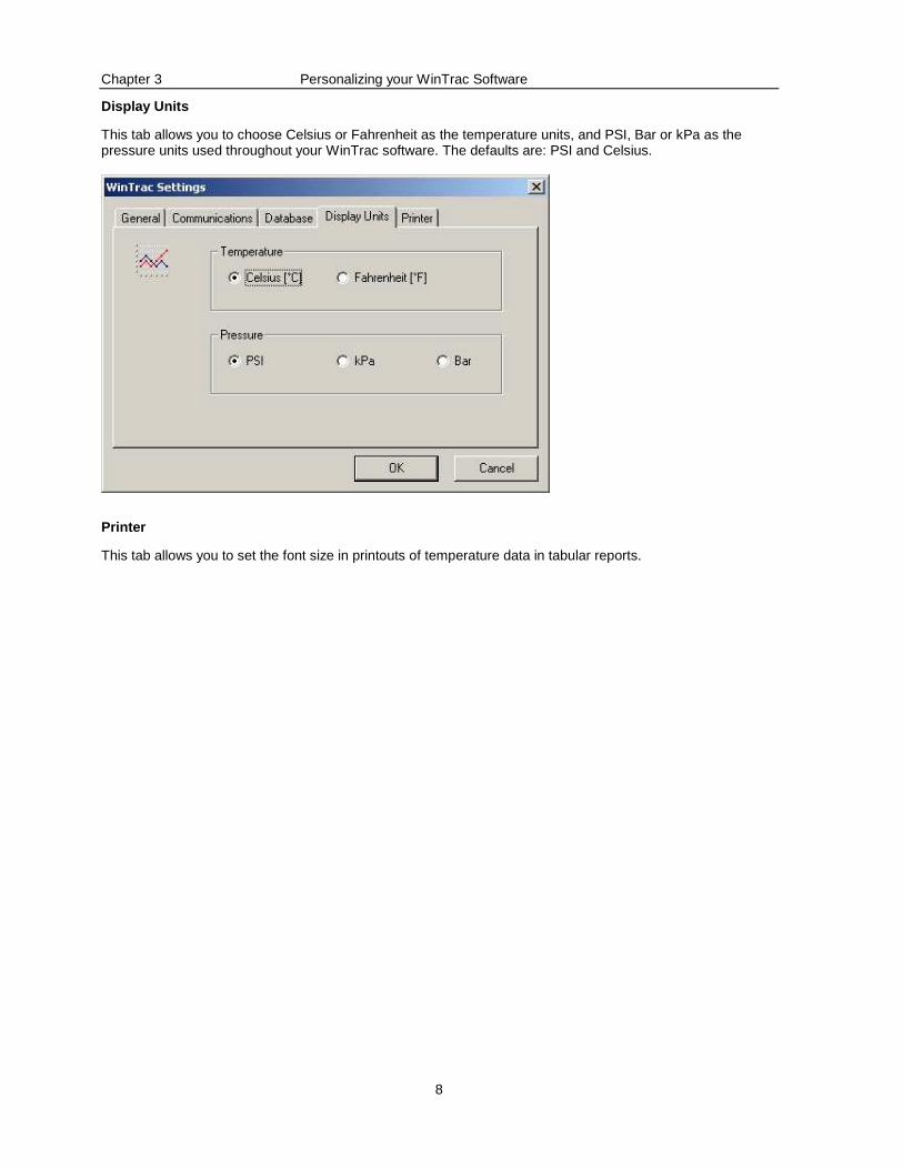
Display Units
This tab allows you to choose Celsius or Fahrenheit as the temperature units, and PSI, Bar or kPa as the pressure units used throughout your WinTrac software. The defaults are: PSI and Celsius.
Printer
This tab allows you to set the font size in printouts of temperature data in tabular reports.
Chapter 4 Communicating with your Thermo King Units
9
Chapter 4
Communicating with your Thermo King Units
This section describes how to communicate with your Thermo King data loggers using WinTrac software. You may view the operating parameters of the Thermo King units, alter certain settings to suit your needs, and download logged data storing it to a file on your PC.
Searching for Thermo King Devices
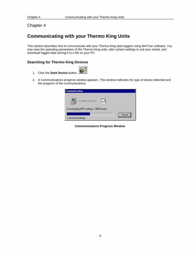
1. Click the Seek Device button.
2. A Communications progress window appears. This window indicates the type of device detected and the progress of the communications.
Communications Progress Window
Chapter 4 Communicating with your Thermo King Units
10
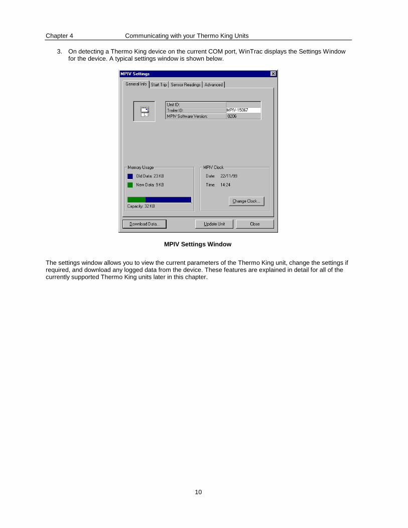
3. On detecting a Thermo King device on the current COM port, WinTrac displays the Settings Window for the device. A typical settings window is shown below.
MPIV Settings Window
The settings window allows you to view the current parameters of the Thermo King unit, change the settings if required, and download any logged data from the device. These features are explained in detail for all of the currently supported Thermo King units later in this chapter.
Chapter 4 Communicating with your Thermo King Units
11
Changing Device Settings
You can easily change the settings of your TK device from the Settings window. Simply change the parameter(s) to the desired new setting, and click on the Update Unit button located at the bottom of the Settings window. WinTrac communicates with the unit and updates the setting(s).
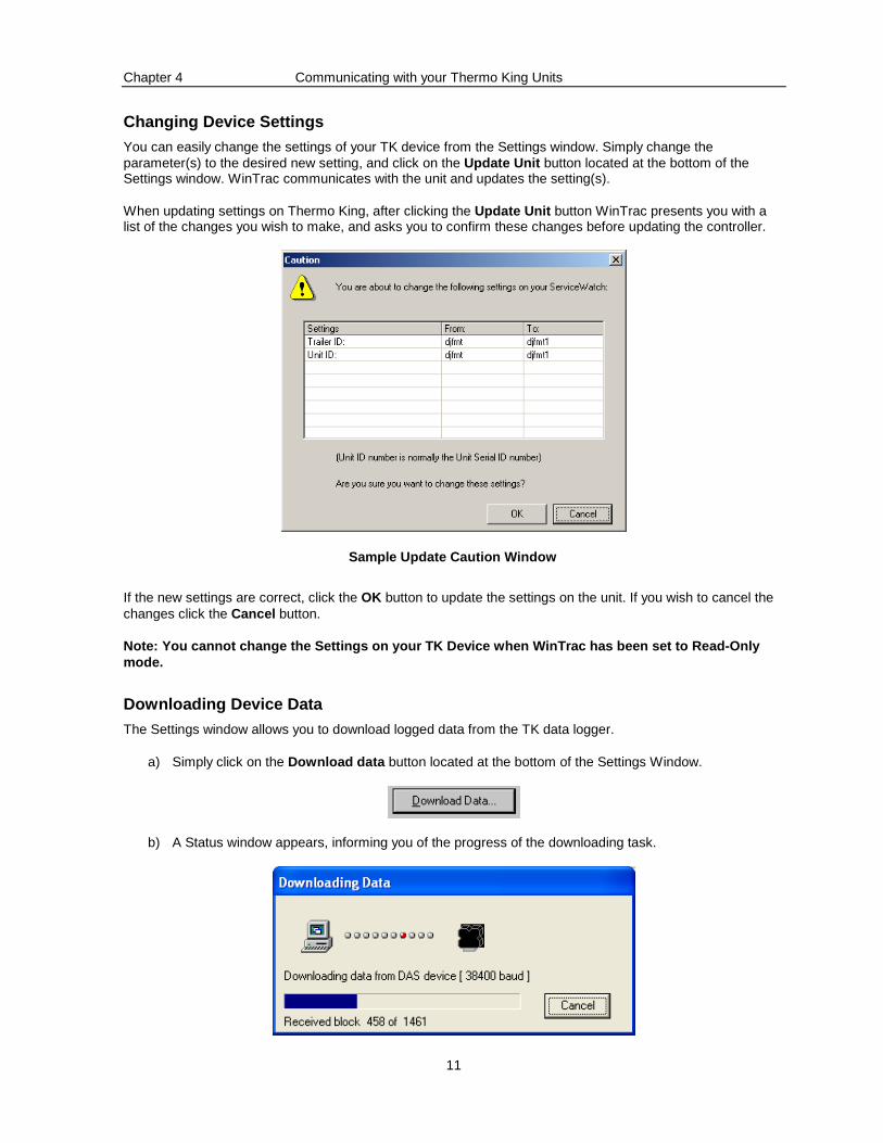
When updating settings on Thermo King, after clicking the Update Unit button WinTrac presents you with a list of the changes you wish to make, and asks you to confirm these changes before updating the controller.
Sample Update Caution Window
If the new settings are correct, click the OK button to update the settings on the unit. If you wish to cancel the changes click the Cancel button.
Note: You cannot change the Settings on your TK Dev ice when WinTrac has been set to Read-Only mode.
Downloading Device Data
The Settings window allows you to download logged data from the TK data logger.
a) Simply click on the Download data button located at the bottom of the Settings Window.
b) A Status window appears, informing you of the progress of the downloading task.
Chapter 4 Communicating with your Thermo King Units
12
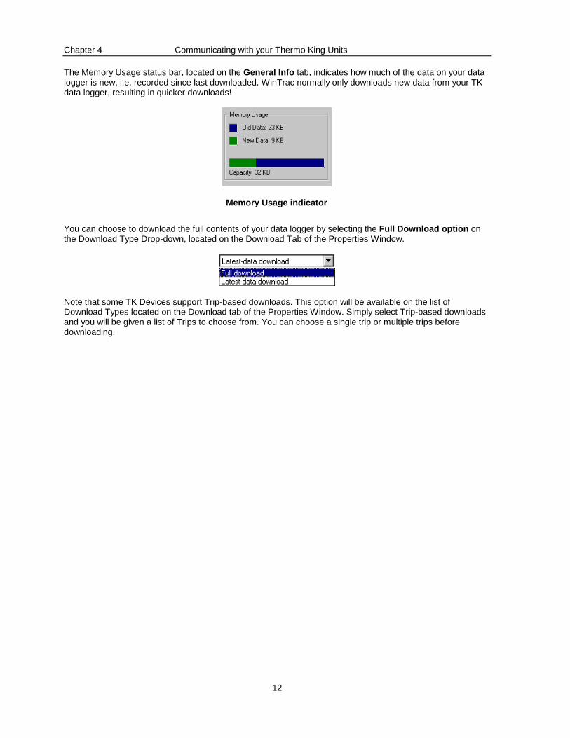
The Memory Usage status bar, located on the General Info tab, indicates how much of the data on your data logger is new, i.e. recorded since last downloaded. WinTrac normally only downloads new data from your TK data logger, resulting in quicker downloads!
Memory Usage indicator
You can choose to download the full contents of your data logger by selecting the Full Download option on the Download Type Drop-down, located on the Download Tab of the Properties Window.
Note that some TK Devices support Trip-based downloads. This option will be available on the list of Download Types located on the Download tab of the Properties Window. Simply select Trip-based downloads and you will be given a list of Trips to choose from. You can choose a single trip or multiple trips before downloading.
Chapter 4 Communicating with your Thermo King Units
13
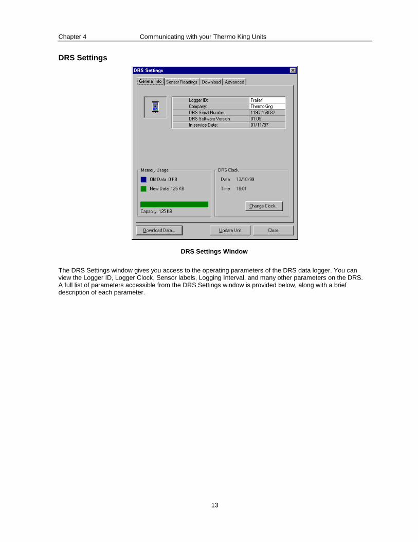
DRS Settings
DRS Settings Window
The DRS Settings window gives you access to the operating parameters of the DRS data logger. You can view the Logger ID, Logger Clock, Sensor labels, Logging Interval, and many other parameters on the DRS. A full list of parameters accessible from the DRS Settings window is provided below, along with a brief description of each parameter.
Chapter 4 Communicating with your Thermo King Units
14
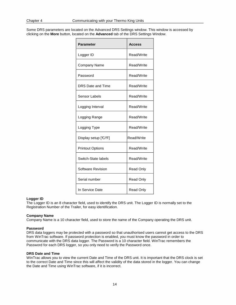
Some DRS parameters are located on the Advanced DRS Settings window. This window is accessed by clicking on the More button, located on the Advanced tab of the DRS Settings Window.
Parameter Access
Logger ID Read/Write
Company Name Read/Write
Password Read/Write
DRS Date and Time Read/Write
Sensor Labels Read/Write
Logging Interval Read/Write
Logging Range Read/Write
Logging Type Read/Write
Display setup [°C/°F] Read/Write
Printout Options Read/Write
Switch-State labels Read/Write
Software Revision Read Only
Serial number Read Only
In Service Date Read Only
Logger ID The Logger ID is an 8 character field, used to identify the DRS unit. The Logger ID is normally set to the Registration Number of the Trailer, for easy identification.
Company Name Company Name is a 10 character field, used to store the name of the Company operating the DRS unit.
Password DRS data loggers may be protected with a password so that unauthorised users cannot get access to the DRS from WinTrac software. If password protection is enabled, you must know the password in order to communicate with the DRS data logger. The Password is a 10 character field. WinTrac remembers the Password for each DRS logger, so you only need to verify the Password once.
DRS Date and Time WinTrac allows you to view the current Date and Time of the DRS unit. It is important that the DRS clock is set to the correct Date and Time since this will affect the validity of the data stored in the logger. You can change the Date and Time using WinTrac software, if it is incorrect.

Chapter 4 Communicating with your Thermo King Units
15
Sensor Labels
The DRS stores labels as 3 characters for the 2 probes and 2 switches on the DRS unit. These labels appear on DRS printouts, and on the display of the DRS. WinTrac also use these labels when displaying sensor information for a particular DRS data logger.
Logging Interval
The DRS logs the readings for each probe and switch each Logging Interval. The logging interval may be set to:
1 min 20 mins 5 mins 30 mins 10 mins 45 mins 15 mins 1 hr
The default logging interval is 15 mins.
Logging Range
The DRS data logger normally logs a range of 60°C. You can select one of four logging ranges to suit your normal range of operation:
-45°C to +15°C -35°C to +25°C -30°C to +30°C -15°C to +45°C
The default logging range is -30°C to +30°C
Logging Type
Logging Type determines the type of log performed by your DRS data logger at the end of each logging interval. The four possible types are: Minimum, Mean, Maximum, and Instantaneous.
• Minimum stores the minimum value measured over the logging interval.
• Mean stores the average value measured over the logging interval.
• Maximum stores the maximum value measured over the logging interval.
• Instantaneous stores the current measured value at the end of the logging interval.
Display Setup (°C/°F)
You can choose the temperature units used when displaying probe readings on the DRS display. You can choose between degrees Celsius or degrees Fahrenheit.
Chapter 4 Communicating with your Thermo King Units
16
Printout Options
There are several printout options available on your DRS data logger when using a hand-held printer. You can set the type of printout type using WinTrac software. The printout options are:
DD/MM/YY - prints data for selected day Delivery - prints data from selected power up to next power up Town - prints data from the currently selected time onwards Dynamic - allows you to choose Printing mode when you print.
Note that older DRS units will not support all printout options, just DD/MM/YY and Delivery.
Switch-State Labels
The DRS data logger stores 4 character labels for the two possible switch states of DRS switch inputs. These labels are used on the DRS display, and also in WinTrac software when displaying switch information.
Software Revision
WinTrac displays the software revision of the DRS unit currently connected to your PC.
Serial Number
WinTrac displays the serial number of your DRS. You should note this serial number as it uniquely identifies your DRS unit.
In Service Date
When you communicate with a DRS data logger for the first time using WinTrac software, your DRS data logger is initialised, and the In Service Date is set on your DRS. This date indicates when the DRS went into service, and may be useful for warranty purposes.
Chapter 4 Communicating with your Thermo King Units
17
Accutrac Settings
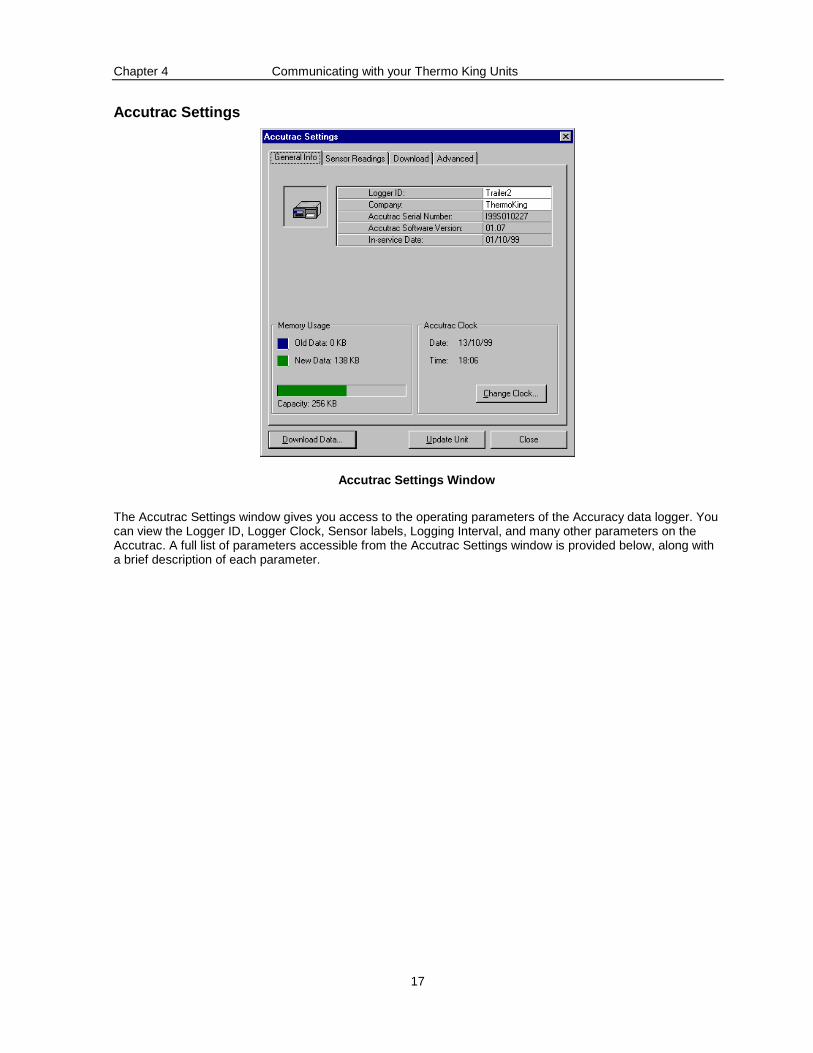
Accutrac Settings Window
The Accutrac Settings window gives you access to the operating parameters of the Accuracy data logger. You can view the Logger ID, Logger Clock, Sensor labels, Logging Interval, and many other parameters on the Accutrac. A full list of parameters accessible from the Accutrac Settings window is provided below, along with a brief description of each parameter.

Chapter 4 Communicating with your Thermo King Units
18
Some Accutrac parameters are located on the Advanced Accutrac Settings window. This window is accessed by clicking on the More… button, located on the Advanced tab of the Accutrac Settings Window.
Parameter Access
Logger ID Read/Write
Company Name Read/Write
Password Read/Write
Date and Time Read/Write
Sensor Labels Read/Write
Logging Interval Read/Write
Logging Type Read/Write
Display setup [°C/°F] Read/Write
Printout Type Read/Write
Printout Format Read/Write
Switch-State labels Read Only
Language Setup Read/Write
Software Revision Read Only
Serial number Read Only
In Service Date Read Only
Logger ID
The Logger ID is an 8 character field, used to identify the Accutrac unit. The Logger ID is normally set to the ID Number of the Truck, for easy identification.
Company Name
Company Name is a 10 character field, used to store the name of the Company operating the Accutrac unit.
Password
Accuracy data loggers may be protected with a password so that unauthorised users cannot get access to the Accutrac from WinTrac software. If password protection is enabled, you must know the password in order to communicate with the Accuracy data logger. The Password is a 10 character field. WinTrac remembers the Password for each Accutrac logger, so you only need to verify the Password once.
Date and Time
WinTrac allows you to view the current Date and Time of the Accutrac unit. It is important that the Accutrac clock is set to the correct Date and Time since this will affect the validity of the data stored in the logger. You can change the Date and Time using WinTrac software, if it is incorrect.
Chapter 4 Communicating with your Thermo King Units
19
Sensor Labels
The Accutrac stores labels as 8 characters for the 4 probes on the unit. These labels appear on Accutrac printouts. WinTrac also uses these labels when displaying sensor information for a particular Accuracy data logger.
Logging Interval
The Accutrac logs the readings for each probe and switch each Logging Interval. The logging interval may be set to:
1 min 20 mins 5 mins 30 mins 10 mins 45 mins 15 mins 1 hr
The default logging interval is 15 mins.
Logging Type
Logging Type determines the type of log performed by your Accuracy data logger at the end of each logging interval. The four possible types are: Minimum, Mean, Maximum, and Instantaneous.
• Minimum stores the minimum value measured over the logging interval.
• Mean stores the average value measured over the logging interval.
• Maximum stores the maximum value measured over the logging interval.
• Instantaneous stores the current measured value at the end of the logging interval.
Display Setup (°C/°F)
You can choose the temperature units used when displaying probe readings on the Accutrac display. You can choose between degrees Celsius or degrees Fahrenheit.
Printout Type
There are several printout options available on your Accuracy data logger when using the printer. You can set the type of printout type using WinTrac software. The printout options are:
DD/MM/YY - prints data for a specific day Delivery - prints data at the time of printing. It does not print any recorded data. HH:MM - prints data from a specific hour on the current day. Trip - prints data at the time of delivery, followed by all data recorded, starting from the most recent data. Manual - allows you to choose Printing mode when you print.
Printout Format
You can choose the format of the Date on your Accuracy printouts and Accuracy display screen. You can choose either DDMM or MMDD format to suit your needs.
Chapter 4 Communicating with your Thermo King Units
20
Switch-State Labels
The Accuracy data logger stores 4 character labels for the two possible switch states of Accuracy switch inputs. These labels are used on the Accuracy display, and also in WinTrac software when displaying switch information. These labels are Read-Only on Accuracy devices.
Language Setup
You can choose to set up your Accuracy to use one of the following languages:
English French German Italian Spanish Norwegian Dutch
Software Revision
WinTrac displays the software revision of the Accuracy unit currently connected to your PC.
Serial Number
WinTrac displays the serial number of your Accuracy. You should note this serial number as it uniquely identifies your Accuracy unit.
In Service Date
When you communicate with an Accuracy data logger for the first time using WinTrac software, your Accuracy data logger is initialised, and the In Service Date is set on your Accuracy. This date indicates when the Accuracy went into service, and may be useful for warranty purposes.
Chapter 4 Communicating with your Thermo King Units
21
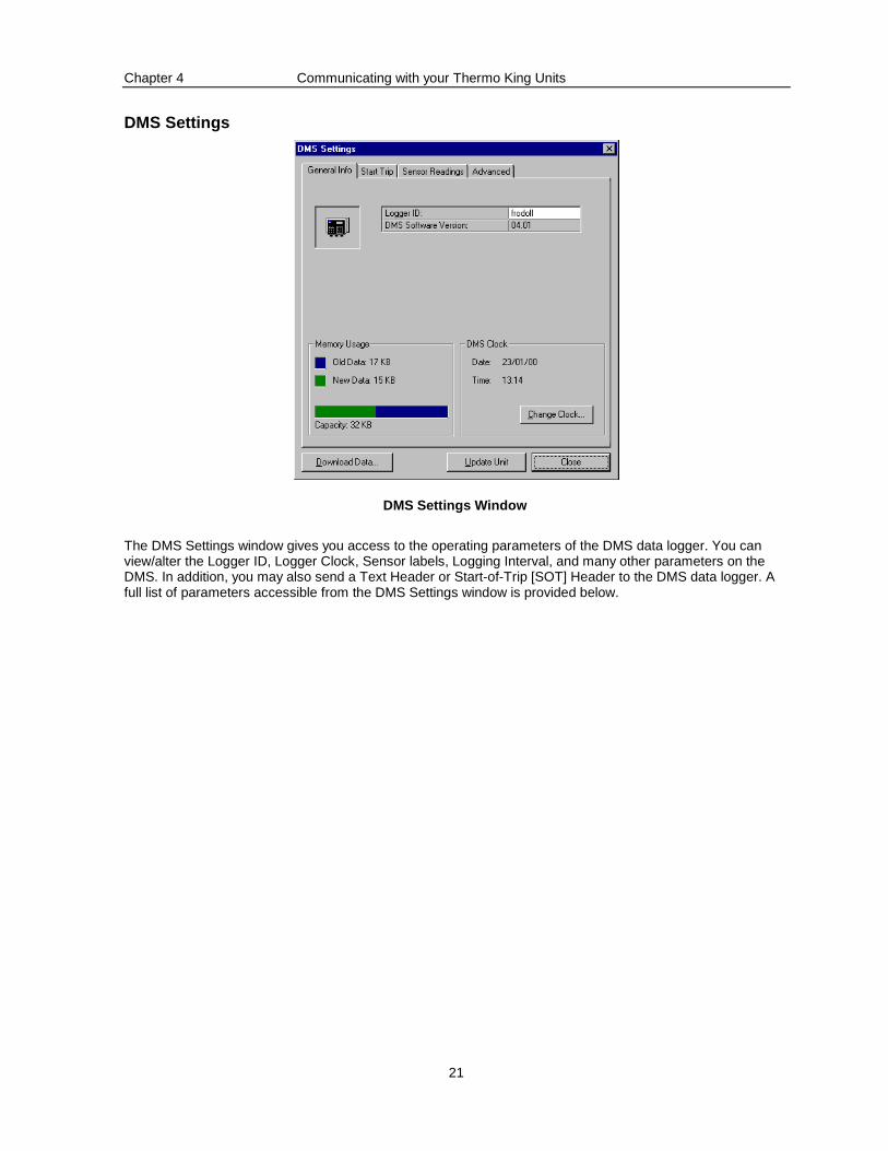
DMS Settings
DMS Settings Window
The DMS Settings window gives you access to the operating parameters of the DMS data logger. You can view/alter the Logger ID, Logger Clock, Sensor labels, Logging Interval, and many other parameters on the DMS. In addition, you may also send a Text Header or Start-of-Trip [SOT] Header to the DMS data logger. A full list of parameters accessible from the DMS Settings window is provided below.
Chapter 4 Communicating with your Thermo King Units
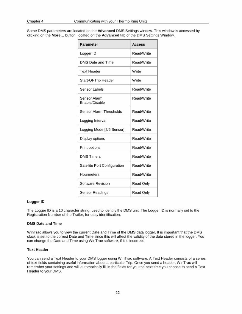
22
Some DMS parameters are located on the Advanced DMS Settings window. This window is accessed by clicking on the More… button, located on the Advanced tab of the DMS Settings Window.
Parameter Access
Logger ID Read/Write
DMS Date and Time Read/Write
Text Header Write
Start-Of-Trip Header Write
Sensor Labels Read/Write
Sensor Alarm Enable/Disable
Read/Write
Sensor Alarm Thresholds Read/Write
Logging Interval Read/Write
Logging Mode [2/6 Sensor] Read/Write
Display options Read/Write
Print options Read/Write
DMS Timers Read/Write
Satellite Port Configuration Read/Write
Hourmeters Read/Write
Software Revision Read Only
Sensor Readings Read Only
Logger ID
The Logger ID is a 10 character string, used to identify the DMS unit. The Logger ID is normally set to the Registration Number of the Trailer, for easy identification.
DMS Date and Time
WinTrac allows you to view the current Date and Time of the DMS data logger. It is important that the DMS clock is set to the correct Date and Time since this will affect the validity of the data stored in the logger. You can change the Date and Time using WinTrac software, if it is incorrect.
Text Header
You can send a Text Header to your DMS logger using WinTrac software. A Text Header consists of a series of text fields containing useful information about a particular Trip. Once you send a header, WinTrac will remember your settings and will automatically fill in the fields for you the next time you choose to send a Text Header to your DMS.
Chapter 4 Communicating with your Thermo King Units
23
Start-of-Trip [SOT] Header
You can send a Start-of-Trip Header to your DMS Loggers using WinTrac software. Simply select the SOT option on the Header Tab, and click on the ‘Send SOT Header’ button.
Sensor Labels
The DMS unit stores the sensor labels with the maximum length of 15 characters for each label. WinTrac uses these labels when displaying sensor information for a particular DMS data logger.
Sensor Alarms
Each Sensor on the DMS data logger has an out-of-range alarm associated with it. An out-of-range alarm will be recorded by the DMS data logger, as well as causing the DMS display to flash. You can enable or disable this alarm capability. You may also define upper and lower temperature thresholds for the out-of-range alarm. To access the alarm settings for the DMS sensors, Click on the Change Settings… button located on the Sensors tab of the DMS properties window.
Logging Interval
The DMS logs the readings for each probe each Logging Interval. The logging interval may be set to 2 mins,5 mins, 10 mins, 15 mins, 30 mins, 1 hour, 2 hours, or 4 hours.
Logging Mode
The DMS data logger can be set to store the readings of the first two sensors (Return Air and Discharge Air), or all six sensors (including the four spare sensors). The Setpoint sensor input is always logged by the DMS data logger.
Display Options
You can choose to enable or disable the DMS display from WinTrac software. You can also choose the temperature units (either °C or °F) used on your DM S display.
Printout Options
There are several printout options available on your DMS data logger when using a hand-held printer. You can choose to enable or disable print completely, as well as enable or disable a chart printout, and exception printing.
Timer Information
The DMS data logger has three timers with user-settable intervals. The three timers are Pull-down out-of-range timer, Defrost timeout timer, and Defrost recovery timer. You can set the interval of these timers using WinTrac software. Timer information is contained on the Advanced DMS Settings window.
Satellite Port
Some DMS units are equipped with a secondary serial port for communications, often referred to as the Satellite Port. You can configure this satellite port to either DataPac, Qualcomm, or remote.
Chapter 4 Communicating with your Thermo King Units
24
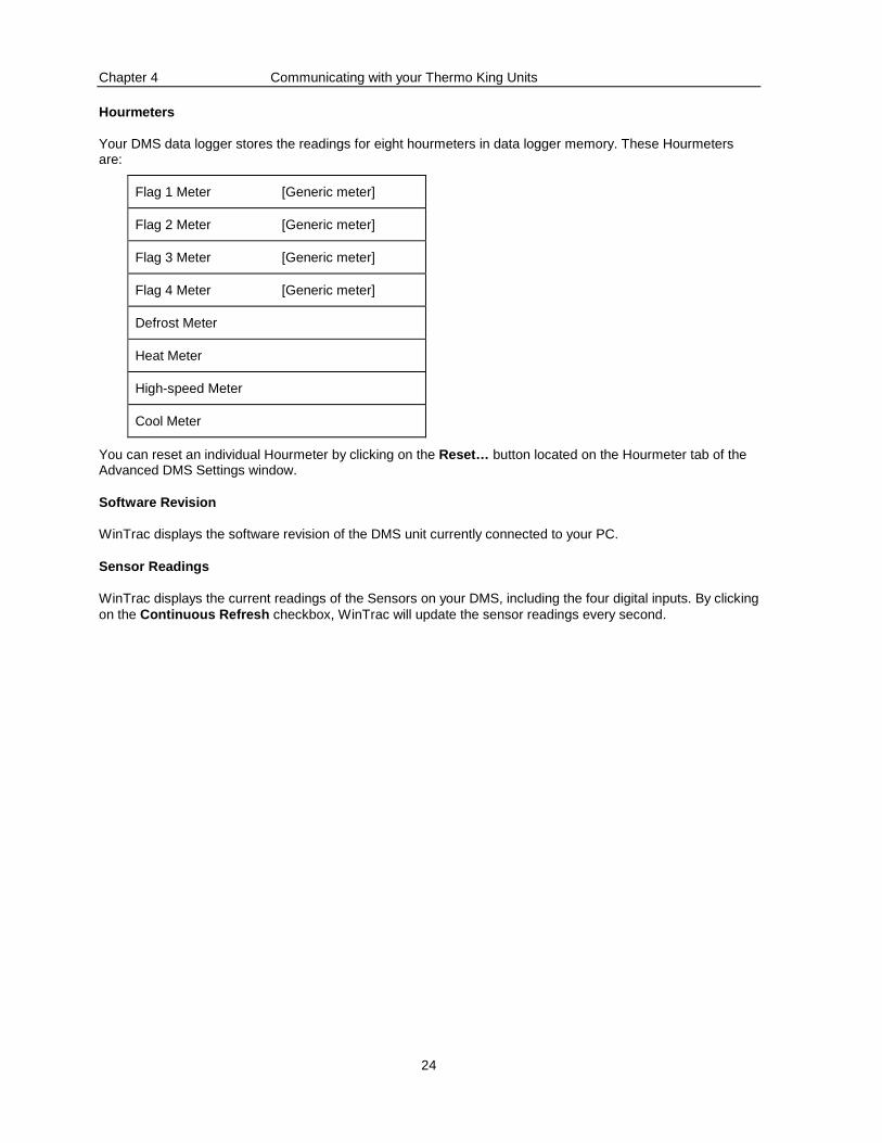
Hourmeters
Your DMS data logger stores the readings for eight hourmeters in data logger memory. These Hourmeters are:
Flag 1 Meter [Generic meter]
Flag 2 Meter [Generic meter]
Flag 3 Meter [Generic meter]
Flag 4 Meter [Generic meter]
Defrost Meter
Heat Meter
High-speed Meter
Cool Meter
You can reset an individual Hourmeter by clicking on the Reset… button located on the Hourmeter tab of the Advanced DMS Settings window.
Software Revision
WinTrac displays the software revision of the DMS unit currently connected to your PC.
Sensor Readings
WinTrac displays the current readings of the Sensors on your DMS, including the four digital inputs. By clicking on the Continuous Refresh checkbox, WinTrac will update the sensor readings every second.
Chapter 4 Communicating with your Thermo King Units
25
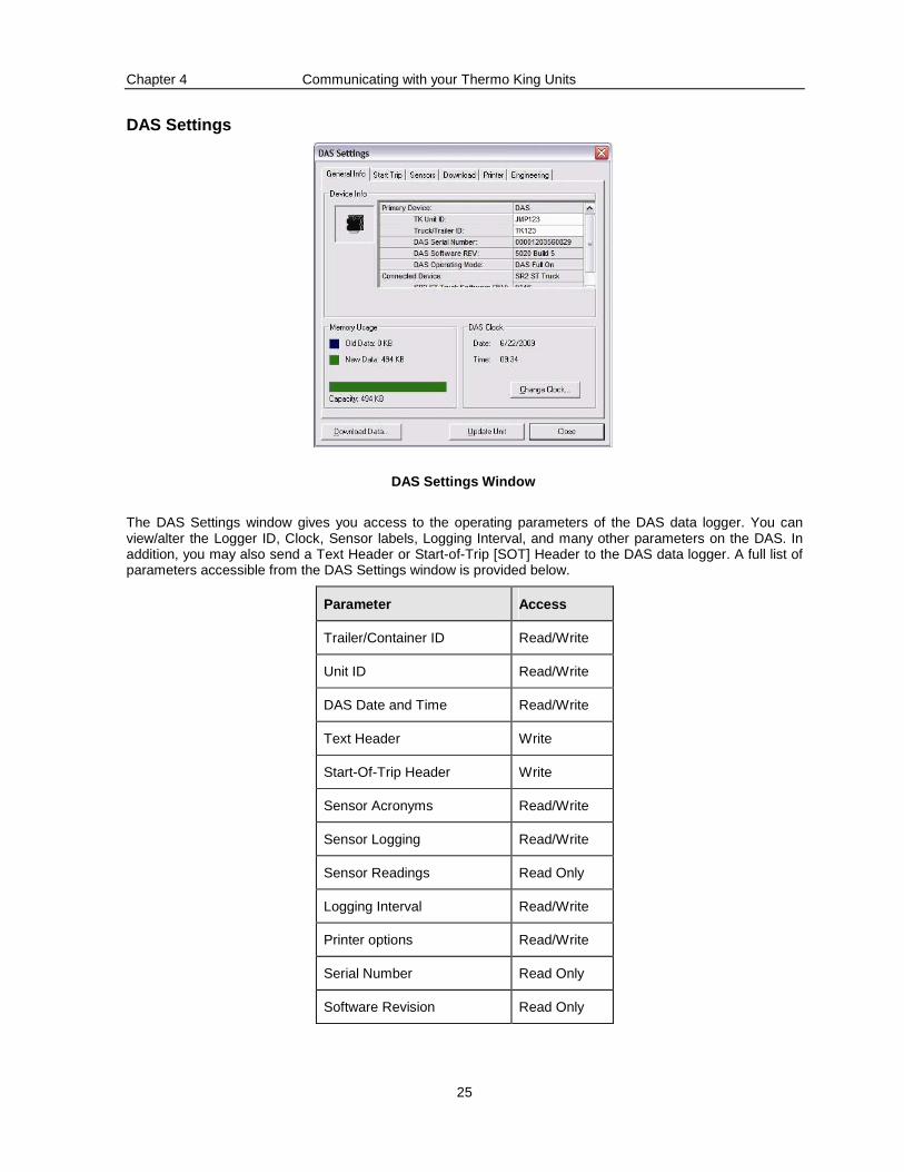
DAS Settings
DAS Settings Window
The DAS Settings window gives you access to the operating parameters of the DAS data logger. You can view/alter the Logger ID, Clock, Sensor labels, Logging Interval, and many other parameters on the DAS. In addition, you may also send a Text Header or Start-of-Trip [SOT] Header to the DAS data logger. A full list of parameters accessible from the DAS Settings window is provided below.
Parameter Access
Trailer/Container ID Read/Write
Unit ID Read/Write
DAS Date and Time Read/Write
Text Header Write
Start-Of-Trip Header Write
Sensor Acronyms Read/Write
Sensor Logging Read/Write
Sensor Readings Read Only
Logging Interval Read/Write
Printer options Read/Write
Serial Number Read Only
Software Revision Read Only
Chapter 4 Communicating with your Thermo King Units
26
Trailer/Container ID
The ID is a 10 character string, used to identify the Thermo King unit. The ID is normally set to the Registration Number of the Trailer or Container, for easy identification.
Unit ID
The Unit ID is a 10 character text field, normally used to store the Unit Serial ID number.
DAS Date and Time
WinTrac allows you to view the current Date and Time of the DAS data logger. It is important that the DAS clock is set to the correct Date and Time since this will affect the validity of the data stored in the logger. You can change the Date and Time using WinTrac software, if it is incorrect.
Text Header
You can send a Text Header to your DAS logger using WinTrac software. A Text Header consists of a series of text fields containing useful information about a particular Trip. Once you send a header, WinTrac will remember your settings and will automatically fill in the fields for you the next time you choose to send a Text Header to your DAS.
Start-of-Trip [SOT] Header
You can send a Start-of-Trip Header to your DAS Loggers using WinTrac software. Simply select the SOT option on the Header Tab, and click on the ‘Send SOT Header’ button.
Sensor Acronym
The DAS unit stores the sensor acronyms with a maximum length of 5 characters for each label. WinTrac uses these acronyms when displaying sensor information for a particular DAS data logger. Simply click on the acronym in the Sensors grid and edit it. Click on ‘Update Unit’ in order to send your changes to the DAS data logger.
Sensor Logging
The DAS data logger allows you to select various logging options for each sensor displayed in the Sensor grid. Simply click on the Logging setting to change it.. Click on ‘Update Unit’ in order to send your changes to the DAS data logger
Logging Interval
The DAS logs the readings for each probe each Logging Interval. The logging interval may be set to 2 mins, 5 mins, 10 mins, 15 mins, 30 mins, 1 hour, 2 hours, or 4 hours.
Printer Options
There are several printout options available on your DAS data logger when using a hand-held printer. You can choose the temperature units (°C or °F), as well as the Date format (dd/mm/yyyy or mm/dd/yyyy).
Software Revision
WinTrac displays the software revision of the DAS unit currently connected to your PC.
Sensor Readings
WinTrac displays the current readings of the Sensors on your DAS, including the three digital inputs. By clicking on the Continuous Refresh checkbox, WinTrac will update the sensor readings every second. If your DAS data logger is connected to a Thermo King controller, you can also see the controller sensors on the Sensors tab of the Settings window.
Tip: For more information on the functionality of these parameters and detailed procedures regarding the Engineering tab, refer to the Thermo King Das (Data Acquisition System) Diagnostic Manual TK 50565.
Chapter 4 Communicating with your Thermo King Units
27
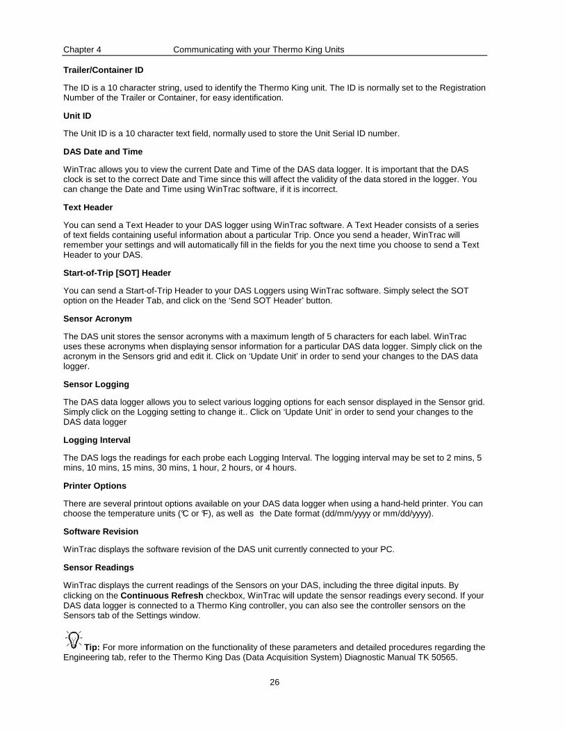
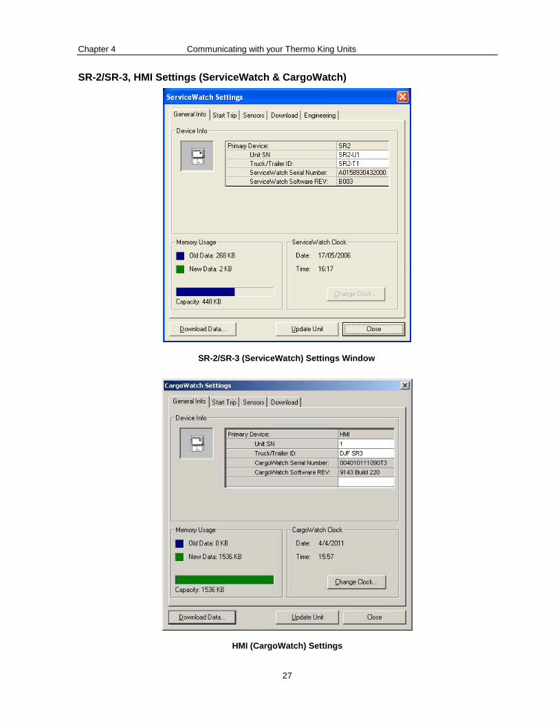
SR-2/SR-3, HMI Settings (ServiceWatch & CargoWatch)
SR-2/SR-3 (ServiceWatch) Settings Window
HMI (CargoWatch) Settings
Chapter 4 Communicating with your Thermo King Units
28
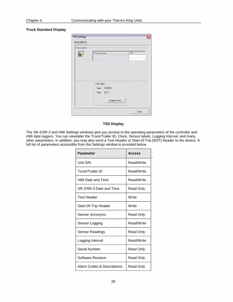
Truck Standard Display
TSD Display
The SR-2/SR-3 and HMI Settings windows give you access to the operating parameters of the controller and HMI data loggers. You can view/alter the Truck/Trailer ID, Clock, Sensor labels, Logging Interval, and many other parameters. In addition, you may also send a Text Header or Start-of-Trip [SOT] Header to the device. A full list of parameters accessible from the Settings window is provided below.
Parameter Access
Unit S/N Read/Write
Truck/Trailer ID Read/Write
HMI Date and Time Read/Write
SR-2/SR-3 Date and Time Read Only
Text Header Write
Start-Of-Trip Header Write
Sensor Acronyms Read Only
Sensor Logging Read/Write
Sensor Readings Read Only
Logging Interval Read/Write
Serial Number Read Only
Software Revision Read Only
Alarm Codes & Descriptions Read Only
Chapter 4 Communicating with your Thermo King Units
29
Unit S/N
The ID is a 10 character string, used to identify the Thermo King unit. The ID is normally set to the Registration Number of the Trailer or Container, for easy identification.
Truck/Trailer ID
The Unit ID is a 10 character text field, normally used to store the Unit Serial ID number.
SR-2/SR-3 & HMI Date and Time
WinTrac allows you to view the current Date and Time of the HMI data logger. It is important that the HMI clock is set to the correct Date and Time since this will affect the validity of the data stored in the logger. You can change the Date and Time using WinTrac software, if it is incorrect. The SR-2/SR-3 clock cannot be set as its value is copied from the attached HMI clock.
Text Header
You can send a Text Header to your SR-2/SR-3 logger using WinTrac software. A Text Header consists of a series of text fields containing useful information about a particular Trip. Once you send a header, WinTrac will remember your settings and will automatically fill in the fields for you the next time you choose to send a Text Header to your SR-2/SR-3.
Start-of-Trip [SOT] Header
You can send a Start-of-Trip Header to your SR-2/SR-3 Loggers using WinTrac software. Simply select the SOT option on the Header Tab, and click on the ‘Send SOT Header’ button.
Sensor Acronym
The SR-2/SR-3/SR-3/SR-3 unit stores the sensor acronyms with a maximum length of 5 characters for each label. WinTrac uses these acronyms when displaying sensor information for a particular SR-2/SR-3 data logger
Sensor Logging
The SR-2/SR-3 data logger allows you to select various logging options for each sensor displayed in the Sensor grid. Simply click on the Logging setting to change it.. Click on ‘Update Unit’ in order to send your changes to the SR-2/SR-3 data logger
Logging Interval
The SR-2/SR-3 logs the readings for each probe each Logging Interval. The logging interval may be set to 2 mins, 5 mins, 10 mins, 15 mins, 30 mins, 1 hour, 2 hours, or 4 hours.
Software Revision
WinTrac displays the software revision of the SR-2/SR-3 unit currently connected to your PC.
Chapter 4 Communicating with your Thermo King Units
30
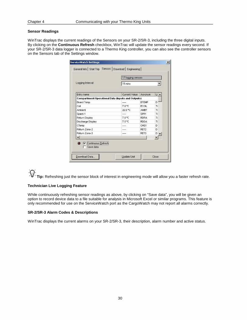
Sensor Readings
WinTrac displays the current readings of the Sensors on your SR-2/SR-3, including the three digital inputs. By clicking on the Continuous Refresh checkbox, WinTrac will update the sensor readings every second. If your SR-2/SR-3 data logger is connected to a Thermo King controller, you can also see the controller sensors on the Sensors tab of the Settings window.
Tip: Refreshing just the sensor block of interest in engineering mode will allow you a faster refresh rate.
Technician Live Logging Feature
While continuously refreshing sensor readings as above, by clicking on “Save data”, you will be given an option to record device data to a file suitable for analysis in Microsoft Excel or similar programs. This feature is only recommended for use on the ServiceWatch port as the CargoWatch may not report all alarms correctly.
SR-2/SR-3 Alarm Codes & Descriptions
WinTrac displays the current alarms on your SR-2/SR-3, their description, alarm number and active status.
Chapter 4 Communicating with your Thermo King Units
31
MPIV, MPV, MPVI Settings
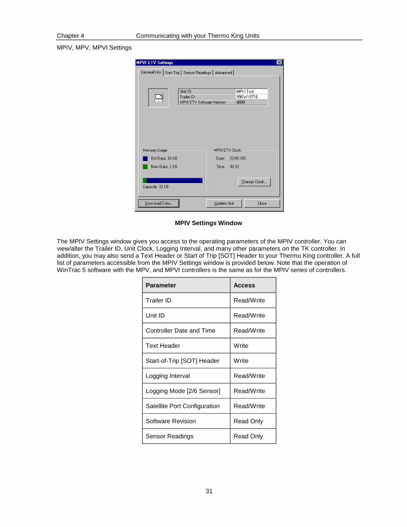
MPIV Settings Window
The MPIV Settings window gives you access to the operating parameters of the MPIV controller. You can view/alter the Trailer ID, Unit Clock, Logging Interval, and many other parameters on the TK controller. In addition, you may also send a Text Header or Start of Trip [SOT] Header to your Thermo King controller. A full list of parameters accessible from the MPIV Settings window is provided below. Note that the operation of WinTrac 5 software with the MPV, and MPVI controllers is the same as for the MPIV series of controllers.
Parameter Access
Trailer ID Read/Write
Unit ID Read/Write
Controller Date and Time Read/Write
Text Header Write
Start-of-Trip [SOT] Header Write
Logging Interval Read/Write
Logging Mode [2/6 Sensor] Read/Write
Satellite Port Configuration Read/Write
Software Revision Read Only
Sensor Readings Read Only
Chapter 4 Communicating with your Thermo King Units
32
Trailer ID
The Trailer ID is a 10 character text field, used to identify the Controller. The Trailer ID is normally set to the Registration Number of the Trailer, for easy identification.
Unit ID
The Unit ID is a 10 character text field, normally used to store the Unit Serial ID number.
Controller Date and Time
WinTrac allows you to view the current Date and Time of the controller. It is important that the controller clock is set to the correct Date and Time since this will affect the data stored on the controller. You can change the Date and Time using WinTrac software, if it is incorrect.
Text Header
You can send a Text Header to your controller using WinTrac software. A Trip Header consists of a series of text fields containing useful information about a particular Trip. Once you send a header, WinTrac will remember your settings and will automatically fill in the fields for you the next time you choose to send a Text Header to your controller.
Start-of-Trip [SOT] Header
You can send a Start-of-Trip Header to your controller using WinTrac software. Simply select the SOT option on the Header Tab, and click on the ‘Send SOT Header’ button.
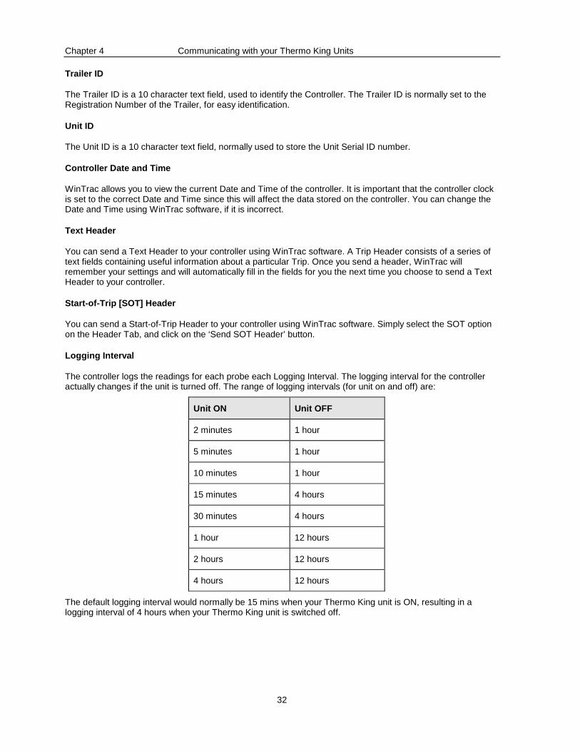
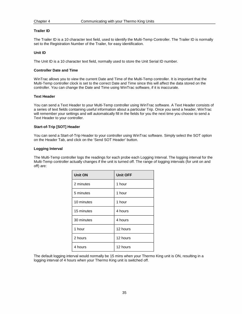
Logging Interval
The controller logs the readings for each probe each Logging Interval. The logging interval for the controller actually changes if the unit is turned off. The range of logging intervals (for unit on and off) are:
Unit ON Unit OFF
2 minutes 1 hour
5 minutes 1 hour
10 minutes 1 hour
15 minutes 4 hours
30 minutes 4 hours
1 hour 12 hours
2 hours 12 hours
4 hours 12 hours
The default logging interval would normally be 15 mins when your Thermo King unit is ON, resulting in a logging interval of 4 hours when your Thermo King unit is switched off.
Chapter 4 Communicating with your Thermo King Units
33
Logging Mode
Most TK controllers store 6 sensors and setpoint sensor by default. Some versions of TK controllers can be configured to store just two sensors (return air and discharge air) and the setpoint. If your controller can change from 6 sensor logging to 2 sensor logging, you can use WinTrac to change this setting.
Satellite Port
MPIV/MPV controllers are equipped with a secondary serial port for communications, often referred to as the Satellite Port. You can configure this satellite port to either DataPac, Qualcomm, or remote.
Software Revision
WinTrac displays the software revision of the controller currently connected to your PC. The software revision is displayed on all screens and printouts of data downloaded from the controller.
Sensor Readings
WinTrac displays the current readings of the Temperature Sensors on your controller. By clicking on the Continuous Refresh checkbox, WinTrac will update the sensor readings every second.
Chapter 4 Communicating with your Thermo King Units
34
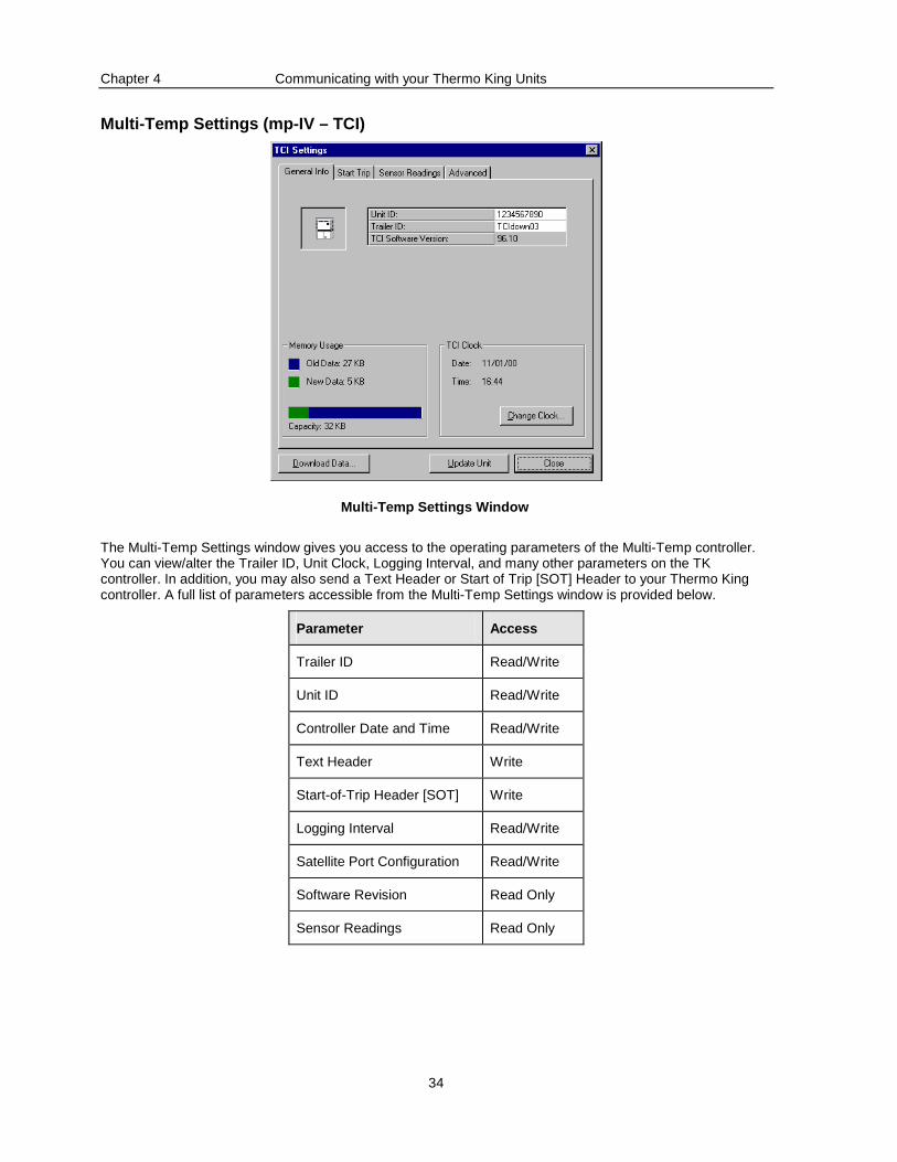
Multi-Temp Settings (mp-IV – TCI)
Multi-Temp Settings Window
The Multi-Temp Settings window gives you access to the operating parameters of the Multi-Temp controller. You can view/alter the Trailer ID, Unit Clock, Logging Interval, and many other parameters on the TK controller. In addition, you may also send a Text Header or Start of Trip [SOT] Header to your Thermo King controller. A full list of parameters accessible from the Multi-Temp Settings window is provided below.
Parameter Access
Trailer ID Read/Write
Unit ID Read/Write
Controller Date and Time Read/Write
Text Header Write
Start-of-Trip Header [SOT] Write
Logging Interval Read/Write
Satellite Port Configuration Read/Write
Software Revision Read Only
Sensor Readings Read Only
Chapter 4 Communicating with your Thermo King Units
35
Trailer ID
The Trailer ID is a 10 character text field, used to identify the Multi-Temp Controller. The Trailer ID is normally set to the Registration Number of the Trailer, for easy identification.
Unit ID
The Unit ID is a 10 character text field, normally used to store the Unit Serial ID number.
Controller Date and Time
WinTrac allows you to view the current Date and Time of the Multi-Temp controller. It is important that the Multi-Temp controller clock is set to the correct Date and Time since this will affect the data stored on the controller. You can change the Date and Time using WinTrac software, if it is inaccurate.
Text Header
You can send a Text Header to your Multi-Temp controller using WinTrac software. A Text Header consists of a series of text fields containing useful information about a particular Trip. Once you send a header, WinTrac will remember your settings and will automatically fill in the fields for you the next time you choose to send a Text Header to your controller.
Start-of-Trip [SOT] Header
You can send a Start-of-Trip Header to your controller using WinTrac software. Simply select the SOT option on the Header Tab, and click on the ‘Send SOT Header’ button.
Logging Interval
The Multi-Temp controller logs the readings for each probe each Logging Interval. The logging interval for the Multi-Temp controller actually changes if the unit is turned off. The range of logging intervals (for unit on and off) are:
Unit ON Unit OFF
2 minutes 1 hour
5 minutes 1 hour
10 minutes 1 hour
15 minutes 4 hours
30 minutes 4 hours
1 hour 12 hours
2 hours 12 hours
4 hours 12 hours
The default logging interval would normally be 15 mins when your Thermo King unit is ON, resulting in a logging interval of 4 hours when your Thermo King unit is switched off.

Chapter 4 Communicating with your Thermo King Units
36
Satellite Port
Multi-Temp controllers are equipped with a secondary serial port for communications, often referred to as the Satellite Port. You can configure this satellite port to either DataPac, Qualcomm, or remote.
Software Revision
WinTrac displays the software revision of the Multi-Temp controller currently connected to your PC. The software revision is displayed on all screens and printouts of data downloaded from a Multi-Temp controller.
Sensor Readings
WinTrac displays the current readings of the Temperature Sensors on your Multi-Temp controller.By clicking on the Continuous Refresh checkbox, WinTrac will update the sensor readings every second.
Chapter 4 Communicating with your Thermo King Units
37
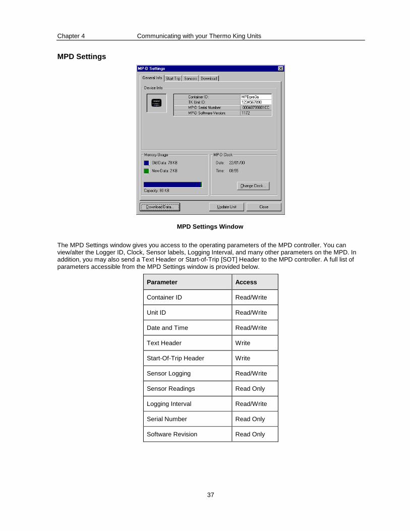
MPD Settings
MPD Settings Window
The MPD Settings window gives you access to the operating parameters of the MPD controller. You can view/alter the Logger ID, Clock, Sensor labels, Logging Interval, and many other parameters on the MPD. In addition, you may also send a Text Header or Start-of-Trip [SOT] Header to the MPD controller. A full list of parameters accessible from the MPD Settings window is provided below.
Parameter Access
Container ID Read/Write
Unit ID Read/Write
Date and Time Read/Write
Text Header Write
Start-Of-Trip Header Write
Sensor Logging Read/Write
Sensor Readings Read Only
Logging Interval Read/Write
Serial Number Read Only
Software Revision Read Only
Chapter 4 Communicating with your Thermo King Units
38
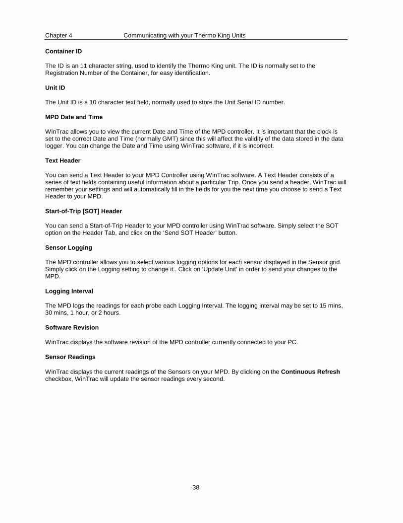
Container ID
The ID is an 11 character string, used to identify the Thermo King unit. The ID is normally set to the Registration Number of the Container, for easy identification.
Unit ID
The Unit ID is a 10 character text field, normally used to store the Unit Serial ID number.
MPD Date and Time
WinTrac allows you to view the current Date and Time of the MPD controller. It is important that the clock is set to the correct Date and Time (normally GMT) since this will affect the validity of the data stored in the data logger. You can change the Date and Time using WinTrac software, if it is incorrect.
Text Header
You can send a Text Header to your MPD Controller using WinTrac software. A Text Header consists of a series of text fields containing useful information about a particular Trip. Once you send a header, WinTrac will remember your settings and will automatically fill in the fields for you the next time you choose to send a Text Header to your MPD.
Start-of-Trip [SOT] Header
You can send a Start-of-Trip Header to your MPD controller using WinTrac software. Simply select the SOT option on the Header Tab, and click on the ‘Send SOT Header’ button.
Sensor Logging
The MPD controller allows you to select various logging options for each sensor displayed in the Sensor grid. Simply click on the Logging setting to change it.. Click on ‘Update Unit’ in order to send your changes to the MPD.
Logging Interval
The MPD logs the readings for each probe each Logging Interval. The logging interval may be set to 15 mins, 30 mins, 1 hour, or 2 hours.
Software Revision
WinTrac displays the software revision of the MPD controller currently connected to your PC.
Sensor Readings
WinTrac displays the current readings of the Sensors on your MPD. By clicking on the Continuous Refresh checkbox, WinTrac will update the sensor readings every second.
Chapter 4 Communicating with your Thermo King Units
39
MPA+, MPA Settings
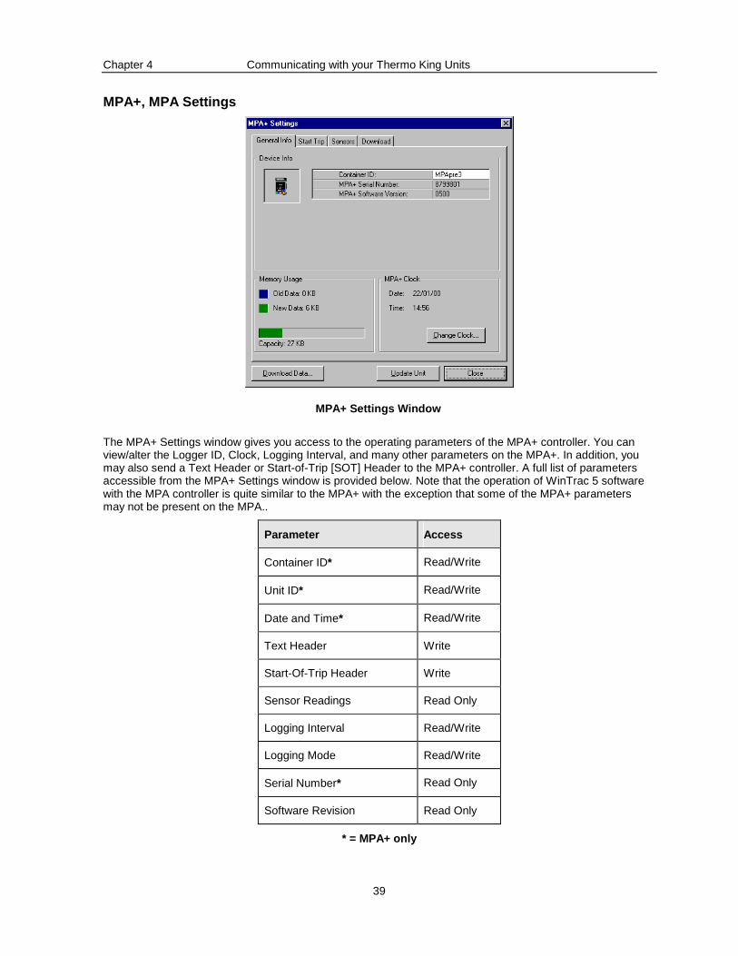
MPA+ Settings Window
The MPA+ Settings window gives you access to the operating parameters of the MPA+ controller. You can view/alter the Logger ID, Clock, Logging Interval, and many other parameters on the MPA+. In addition, you may also send a Text Header or Start-of-Trip [SOT] Header to the MPA+ controller. A full list of parameters accessible from the MPA+ Settings window is provided below. Note that the operation of WinTrac 5 software with the MPA controller is quite similar to the MPA+ with the exception that some of the MPA+ parameters may not be present on the MPA..
Parameter Access
Container ID* Read/Write
Unit ID* Read/Write
Date and Time* Read/Write
Text Header Write
Start-Of-Trip Header Write
Sensor Readings Read Only
Logging Interval Read/Write
Logging Mode Read/Write
Serial Number* Read Only
Software Revision Read Only
* = MPA+ only
Chapter 4 Communicating with your Thermo King Units
40
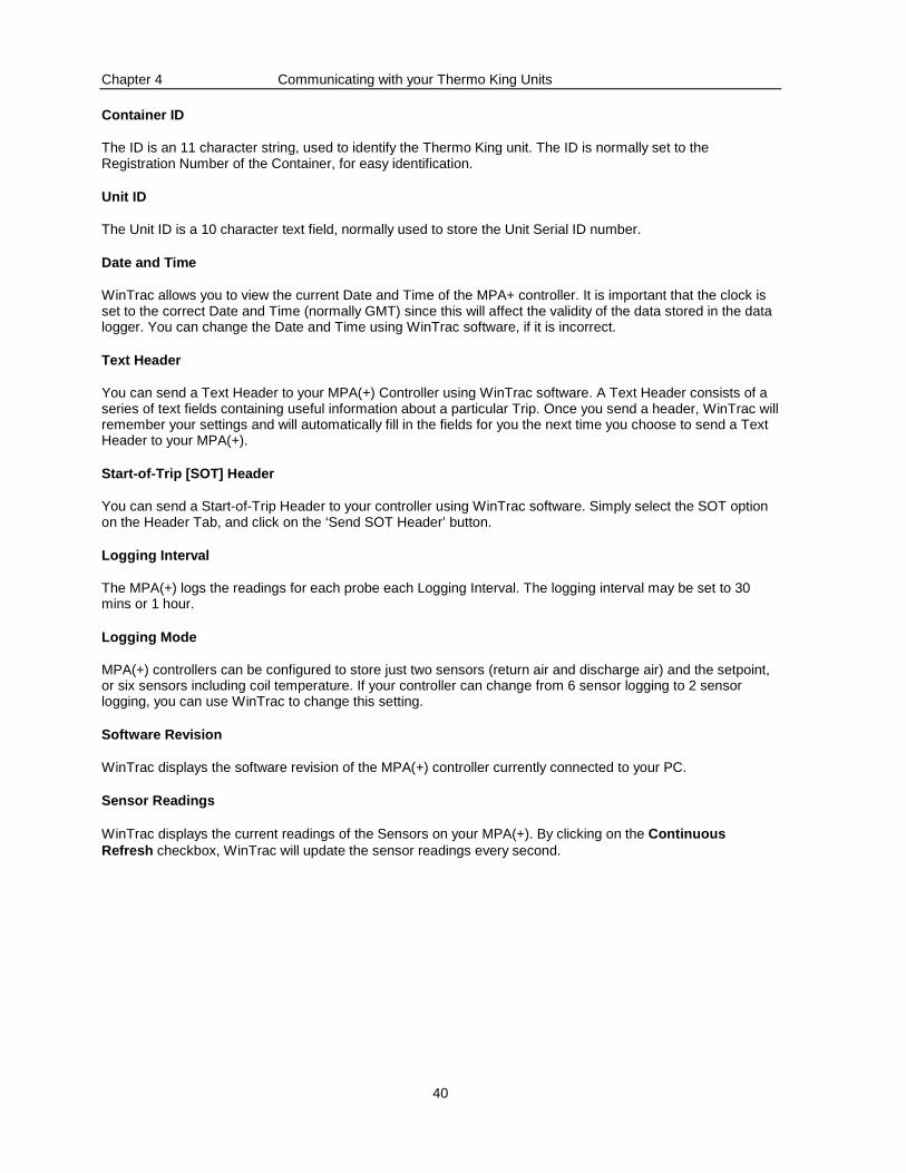
Container ID
The ID is an 11 character string, used to identify the Thermo King unit. The ID is normally set to the Registration Number of the Container, for easy identification.
Unit ID
The Unit ID is a 10 character text field, normally used to store the Unit Serial ID number.
Date and Time
WinTrac allows you to view the current Date and Time of the MPA+ controller. It is important that the clock is set to the correct Date and Time (normally GMT) since this will affect the validity of the data stored in the data logger. You can change the Date and Time using WinTrac software, if it is incorrect.
Text Header
You can send a Text Header to your MPA(+) Controller using WinTrac software. A Text Header consists of a series of text fields containing useful information about a particular Trip. Once you send a header, WinTrac will remember your settings and will automatically fill in the fields for you the next time you choose to send a Text Header to your MPA(+).
Start-of-Trip [SOT] Header
You can send a Start-of-Trip Header to your controller using WinTrac software. Simply select the SOT option on the Header Tab, and click on the ‘Send SOT Header’ button.
Logging Interval
The MPA(+) logs the readings for each probe each Logging Interval. The logging interval may be set to 30 mins or 1 hour.
Logging Mode
MPA(+) controllers can be configured to store just two sensors (return air and discharge air) and the setpoint, or six sensors including coil temperature. If your controller can change from 6 sensor logging to 2 sensor logging, you can use WinTrac to change this setting.
Software Revision
WinTrac displays the software revision of the MPA(+) controller currently connected to your PC.
Sensor Readings
WinTrac displays the current readings of the Sensors on your MPA(+). By clicking on the Continuous Refresh checkbox, WinTrac will update the sensor readings every second.
Chapter 4 Communicating with your Thermo King Units
41
MPCR Settings
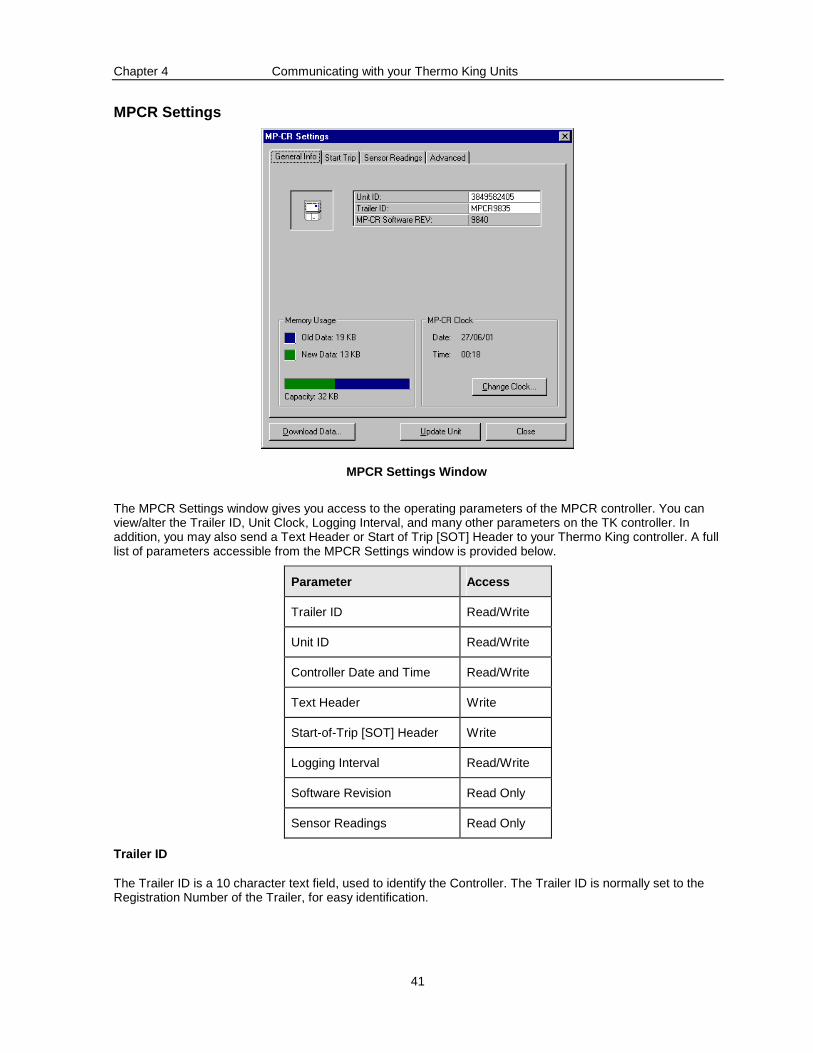
MPCR Settings Window
The MPCR Settings window gives you access to the operating parameters of the MPCR controller. You can view/alter the Trailer ID, Unit Clock, Logging Interval, and many other parameters on the TK controller. In addition, you may also send a Text Header or Start of Trip [SOT] Header to your Thermo King controller. A full list of parameters accessible from the MPCR Settings window is provided below.
Parameter Access
Trailer ID Read/Write
Unit ID Read/Write
Controller Date and Time Read/Write
Text Header Write
Start-of-Trip [SOT] Header Write
Logging Interval Read/Write
Software Revision Read Only
Sensor Readings Read Only
Trailer ID
The Trailer ID is a 10 character text field, used to identify the Controller. The Trailer ID is normally set to the Registration Number of the Trailer, for easy identification.
Chapter 4 Communicating with your Thermo King Units
42
Unit ID
The Unit ID is a 10 character text field, normally used to store the Unit Serial ID number.
Controller Date and Time
WinTrac allows you to view the current Date and Time of the controller. It is important that the controller clock is set to the correct Date and Time since this will affect the data stored on the controller. You can change the Date and Time using WinTrac software, if it is incorrect.
Text Header
You can send a Text Header to your controller using WinTrac software. A Trip Header consists of a series of text fields containing useful information about a particular Trip. Once you send a header, WinTrac will remember your settings and will automatically fill in the fields for you the next time you choose to send a Text Header to your controller.
Start-of-Trip [SOT] Header
You can send a Start-of-Trip Header to your controller using WinTrac software. Simply select the SOT option on the Header Tab, and click on the ‘Send SOT Header’ button.
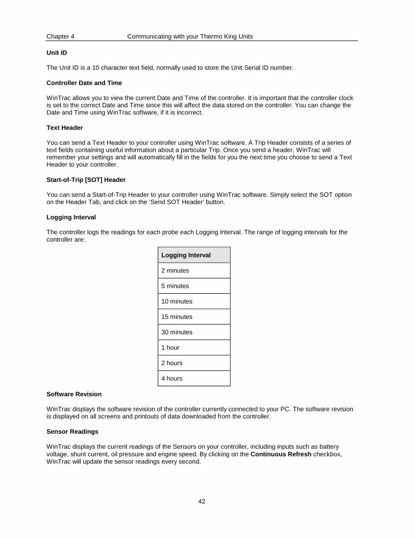
Logging Interval
The controller logs the readings for each probe each Logging Interval. The range of logging intervals for the controller are:
Logging Interval
2 minutes
5 minutes
10 minutes
15 minutes
30 minutes
1 hour
2 hours
4 hours
Software Revision
WinTrac displays the software revision of the controller currently connected to your PC. The software revision is displayed on all screens and printouts of data downloaded from the controller.
Sensor Readings
WinTrac displays the current readings of the Sensors on your controller, including inputs such as battery voltage, shunt current, oil pressure and engine speed. By clicking on the Continuous Refresh checkbox, WinTrac will update the sensor readings every second.
Chapter 4 Communicating with your Thermo King Units
43
TranScan Settings
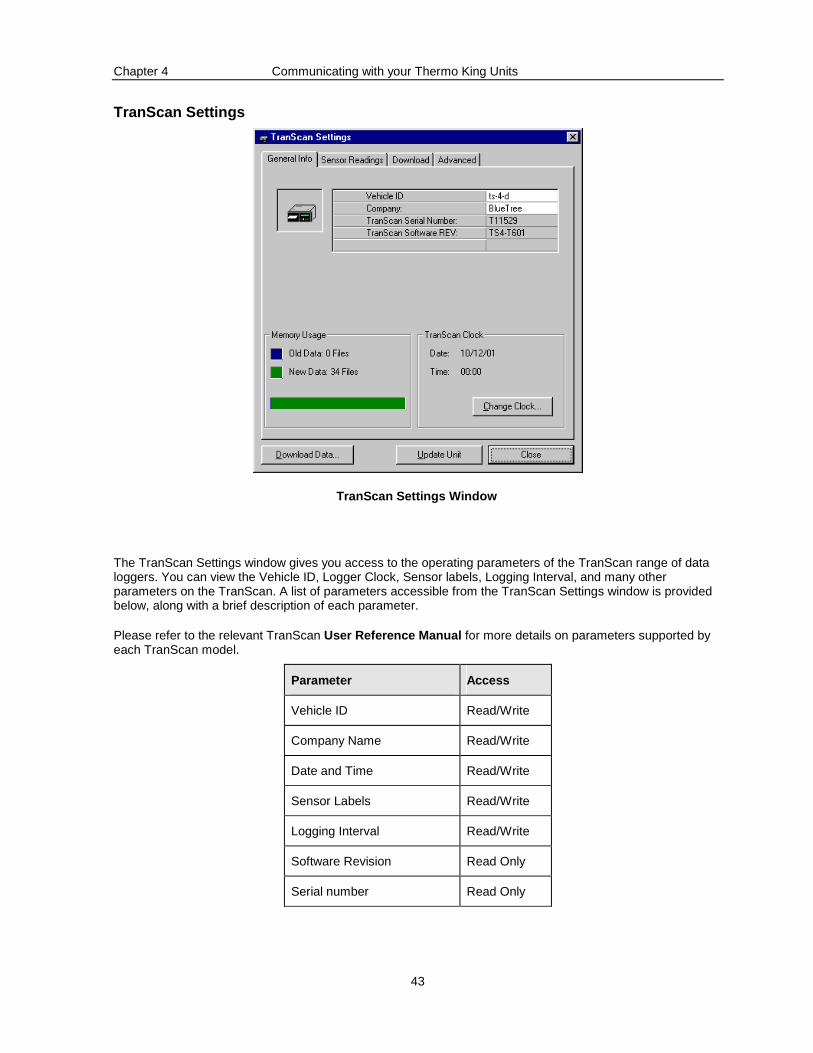
TranScan Settings Window
The TranScan Settings window gives you access to the operating parameters of the TranScan range of data loggers. You can view the Vehicle ID, Logger Clock, Sensor labels, Logging Interval, and many other parameters on the TranScan. A list of parameters accessible from the TranScan Settings window is provided below, along with a brief description of each parameter.
Please refer to the relevant TranScan User Reference Manual for more details on parameters supported by each TranScan model.
Parameter Access
Vehicle ID Read/Write
Company Name Read/Write
Date and Time Read/Write
Sensor Labels Read/Write
Logging Interval Read/Write
Software Revision Read Only
Serial number Read Only
Chapter 4 Communicating with your Thermo King Units
44
Vehicle ID
The Vehicle ID is a 7 character field, used to identify the TranScan unit. The Vehicle ID is normally set to the ID Number of the Truck, for easy identification.
Company Name
Company Name is a 14 character field, used to store the name of the Company operating the TranScan unit.
Date and Time
WinTrac allows you to view the current Date and Time of the TranScan unit. It is important that the TranScan clock is set to the correct Date and Time since this will affect the validity of the data stored in the logger. You can change the Date and Time using WinTrac software, if it is incorrect.
Sensor Labels
The TranScan stores labels as 7 characters for each probe on the unit. These labels appear on TranScan printouts. WinTrac also uses these labels when displaying sensor information for a particular TranScan data logger.
Logging Interval
The TranScan logs the readings for each probe and switch each Logging Interval. The logging interval may be set to:
1 min 20 mins 5 mins 30 mins 10 mins 45 mins 15 mins 1 hr
The default logging interval is 15 mins.
Software Revision
WinTrac displays the software revision of the TranScan unit currently connected to your PC.
Serial Number
WinTrac displays the serial number of your TranScan. You should note this serial number as it uniquely identifies your TranScan unit.
Note: More advanced parameters are available on the Advanced tab of the TranScan Properties window.
Chapter 4 Communicating with your Thermo King Units
45
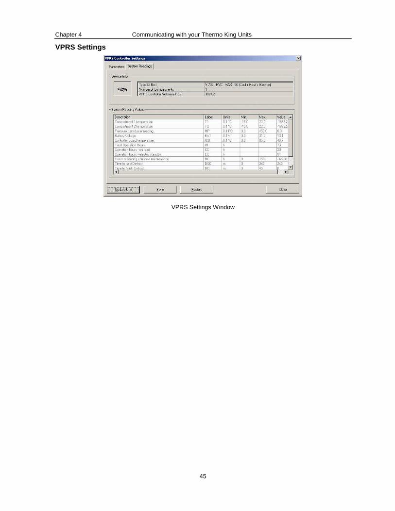
VPRS Settings
VPRS Settings Window
Chapter 4 Communicating with your Thermo King Units
46
NOTE: USB Flash Drive was not originally released o n units built in Europe.
Support SR-3 platform – D000 (all basic support):
a. Flash load WinTrac now supports the flash loading of .m28 files on the SR-3 Controller and .m80 files on the HMI.
b. Download data i. Viewing of downloaded files in Graphical and Tabular format.
c. OptiSet plus upload and download
d. Service modification
NOTE: USB Flash Drive was an option available on un its built in the United States starting with D005 release.
Support SR-3 platform – D005
a. Configuration of USB Flash Drive
b. Manage flash files on USB Flash Drive
c. Manage downloaded files on USB Flash Drive
d. Translation of OptiSet Plus interchange XML file contents into Datapac commands in .osp file format and vice-versa.
Conditions made for SR-3 (new feature support):
a. The flash load, download or OptiSet Plus related files shall not be hidden once placed in the USB Flash Drive.
b. User may store other files on the USB Flash Drive other than Thermo King related files but this would potentially affect download capacity on the USB Flash Drive.
c. All the downloaded data logger files will be in the .wtd raw file format.
d. Flash load files will have file extension .fla,
e. An OptiSet Plus file that needs to be uploaded must have .osp file extension.
Chapter 4 Communicating with your Thermo King Units
47
Initial WinTrac setup to access USB Flash Drive:
1. WinTrac user modes in which USB Flash Drive support shall be accessible are:
• Normal user mode
• Technician user mode
• Engineering user mode
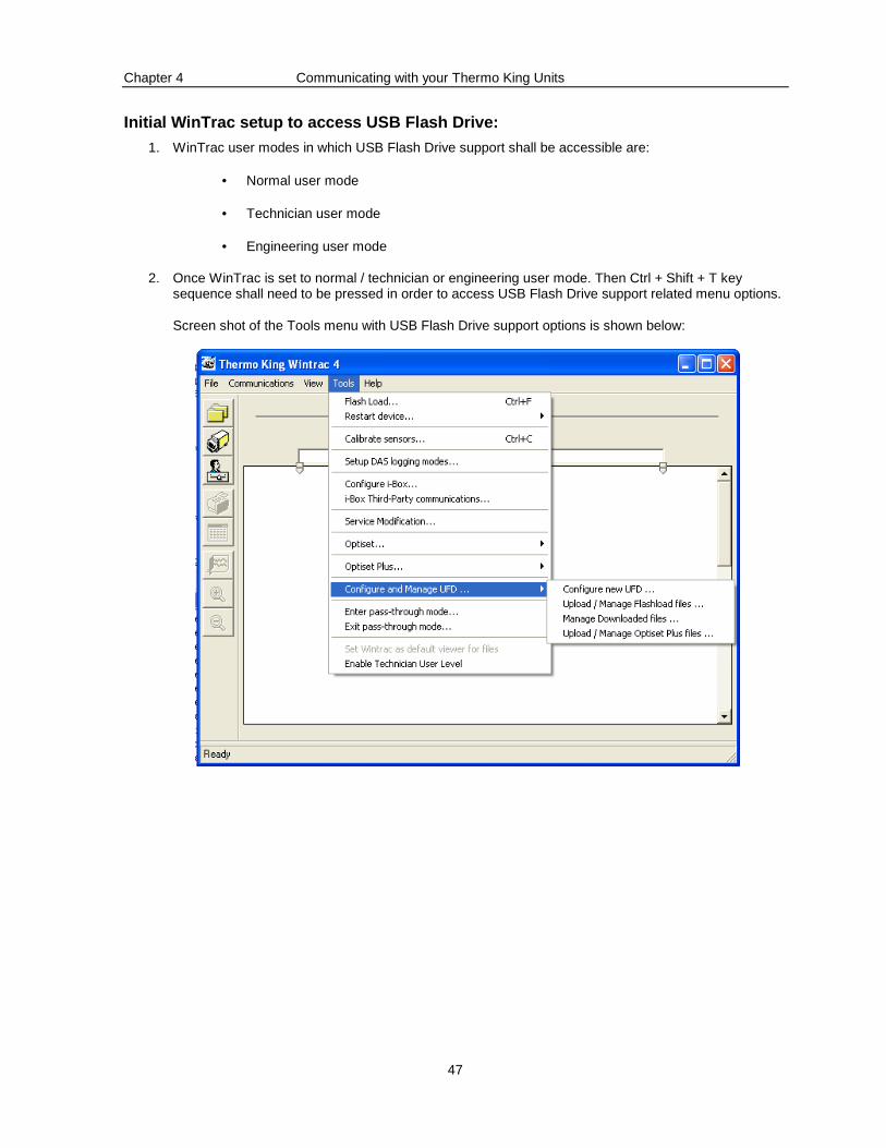
2. Once WinTrac is set to normal / technician or engineering user mode. Then Ctrl + Shift + T key sequence shall need to be pressed in order to access USB Flash Drive support related menu options.
Screen shot of the Tools menu with USB Flash Drive support options is shown below:
Chapter 4 Communicating with your Thermo King Units
48
3. Insertion of USB Flash Drive into PC:
a. At the time of invoking WinTrac, on startup / loading, WinTrac shall check if there is a USB Flash Drive plugged into any of the existing USB ports on the PC.
i. If there is already a USB Flash Drive plugged into the PC, then based on the mandatory WinTrac user mode it shall enable the option of ‘Configure and Manage USB Flash Drive ..’ in Tools menu.
ii. If there is no USB Flash Drive plugged into the PC, then based on the user mode, WinTrac shall disable or gray out the option of ‘Configure and Manage USB Flash Drive …’ in Tools menu.
b. In case the USB Flash Drive is inserted into the PC ‘after ’ invoking WinTrac application, then based on the user mode, WinTrac shall check for the existence of the USB Flash Drive at any of the available USB ports, when the user presses Ctrl + Shift + T key sequence. Accordingly, it shall then enable the ‘Configure and Manage USB Flash Drive …’ option.
Configuration of USB Flash Drive using WinTrac:
Selection of configuring USB Flash Drive using WinTrac:
1. The user shall need to browse to ‘Tools > Configure and Manage USB Flash Drive > Configure USB Flash Drive’ to be able to configure the USB Flash Drive.
2. Once the user selects the above option, WinTrac queries the PC / laptop and identifies the USB Flash Drive and stores the USB Flash Drive_ID internally. WinTrac shall access the ‘Device instance id’ standard USB identifier which is unique for every USB Flash Drive
3. WinTrac detects single USB Flash Drive plugged into PC / laptop:
Once detected, WinTrac shall first check the USB Flash Drive for the presence of any already existing TKConfig.ini file and the mandatory folder structure.
In case none of the above are present in the USB Flash Drive and the USB Flash Drive has not been previously configured, then WinTrac shall display a message ‘Do you want to configure USB Flash Drive?’ (Options provided: Yes and No).
If user selects Yes:
♦ Creation of TKConfig.ini file:
WinTrac shall display a new form with the following fields listed below for the user to input. These are mandatory fields that the user shall need to input to be able to proceed. This information shall be used to write into the TKConfig.ini configuration file that WinTrac shall create in the USB Flash Drive.
♦ Company Name
♦ Author Name
The other information that WinTrac shall write into the TKConfig.ini are:
♦ USB Flash Drive Serial number
♦ Creation Date
WinTrac shall retrieve the USB Flash Drive serial number from the connected USB Flash Drive and shall also enter the Creation date to be the current PC system date.
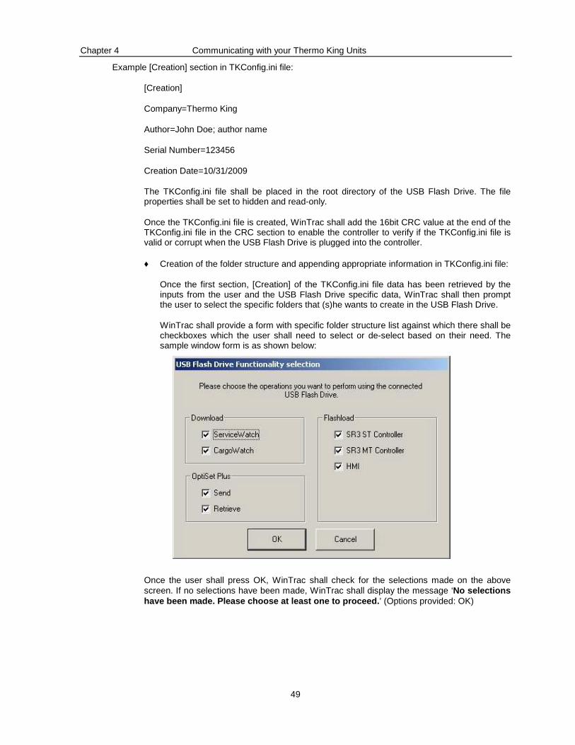
Chapter 4 Communicating with your Thermo King Units
49
Example [Creation] section in TKConfig.ini file:
[Creation]
Company=Thermo King
Author=John Doe; author name
Serial Number=123456
Creation Date=10/31/2009
The TKConfig.ini file shall be placed in the root directory of the USB Flash Drive. The file properties shall be set to hidden and read-only.
Once the TKConfig.ini file is created, WinTrac shall add the 16bit CRC value at the end of the TKConfig.ini file in the CRC section to enable the controller to verify if the TKConfig.ini file is valid or corrupt when the USB Flash Drive is plugged into the controller.
♦ Creation of the folder structure and appending appropriate information in TKConfig.ini file:
Once the first section, [Creation] of the TKConfig.ini file data has been retrieved by the inputs from the user and the USB Flash Drive specific data, WinTrac shall then prompt the user to select the specific folders that (s)he wants to create in the USB Flash Drive.
WinTrac shall provide a form with specific folder structure list against which there shall be checkboxes which the user shall need to select or de-select based on their need. The sample window form is as shown below:
Once the user shall press OK, WinTrac shall check for the selections made on the above screen. If no selections have been made, WinTrac shall display the message ‘No selections have been made. Please choose at least one to proce ed.’ (Options provided: OK)
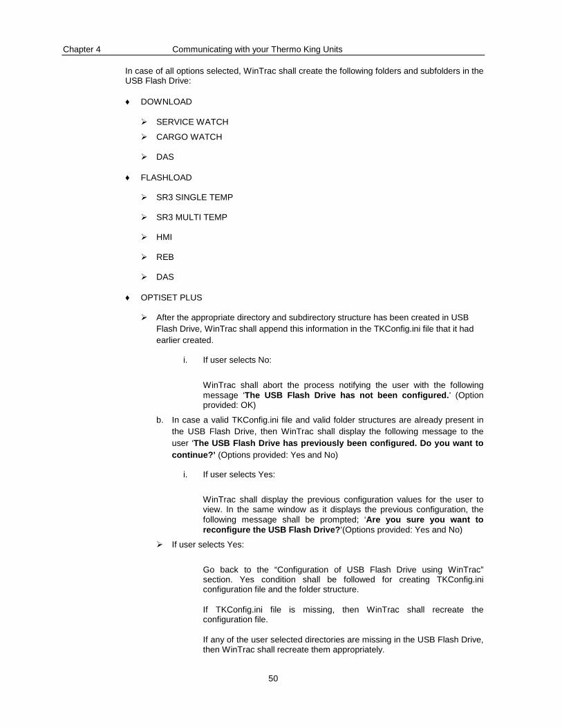
Chapter 4 Communicating with your Thermo King Units
50
In case of all options selected, WinTrac shall create the following folders and subfolders in the USB Flash Drive:
♦ DOWNLOAD
� SERVICE WATCH
� CARGO WATCH
� DAS
♦ FLASHLOAD
� SR3 SINGLE TEMP
� SR3 MULTI TEMP
� HMI
� REB
� DAS
♦ OPTISET PLUS
� After the appropriate directory and subdirectory structure has been created in USB Flash Drive, WinTrac shall append this information in the TKConfig.ini file that it had earlier created.
i. If user selects No:
WinTrac shall abort the process notifying the user with the following message ‘The USB Flash Drive has not been configured. ’ (Option provided: OK)
b. In case a valid TKConfig.ini file and valid folder structures are already present in the USB Flash Drive, then WinTrac shall display the following message to the user ‘The USB Flash Drive has previously been configured. Do you want to continue?’ (Options provided: Yes and No)
i. If user selects Yes:
WinTrac shall display the previous configuration values for the user to view. In the same window as it displays the previous configuration, the following message shall be prompted; ‘Are you sure you want to reconfigure the USB Flash Drive? ’(Options provided: Yes and No)
� If user selects Yes:
Go back to the “Configuration of USB Flash Drive using WinTrac” section. Yes condition shall be followed for creating TKConfig.ini configuration file and the folder structure.
If TKConfig.ini file is missing, then WinTrac shall recreate the configuration file.
If any of the user selected directories are missing in the USB Flash Drive, then WinTrac shall recreate them appropriately.

Chapter 4 Communicating with your Thermo King Units
51
� If user selects No:
WinTrac shall abort the process notifying the user with the following message ‘The USB Flash Drive has not been re-configured. ’ (Option provided: OK)
4. WinTrac detects multiple USB Flash Drive devices plugged into PC / laptop:
In case WinTrac detects multiple USB Flash Drive plugged in the PC / laptop it shall display the following message to the user; ‘Multiple USB Flash Drive devices detected. Please make sure that only one USB Flash Drive device is c onnected to the PC and retry. ’
Once the user remedies the scenario by making sure only one USB Flash Drive is connected, the user shall need to restart the operation by selecting ‘Tools > Configure and Manage USB Flash Drive > Configure new USB Flash Drive’.
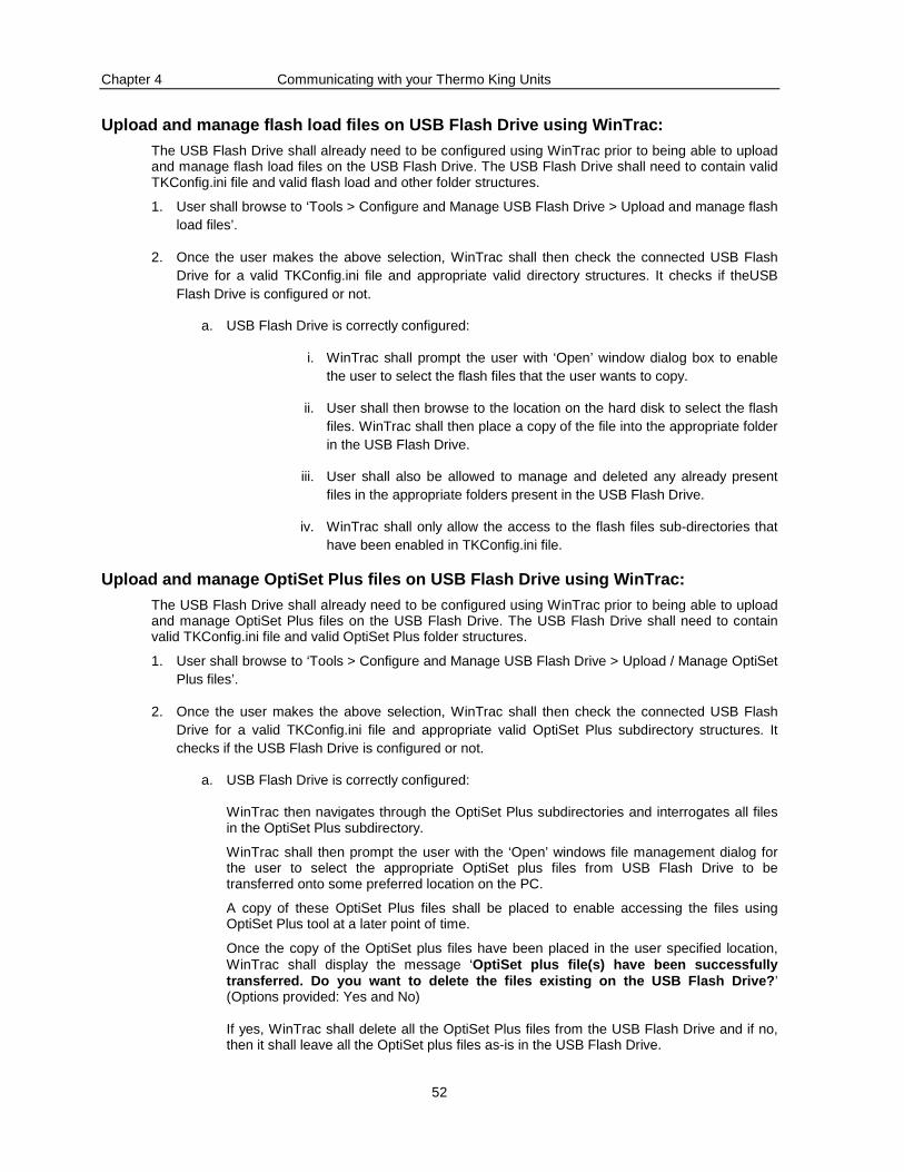
Chapter 4 Communicating with your Thermo King Units
52
Upload and manage flash load files on USB Flash Dri ve using WinTrac:
The USB Flash Drive shall already need to be configured using WinTrac prior to being able to upload and manage flash load files on the USB Flash Drive. The USB Flash Drive shall need to contain valid TKConfig.ini file and valid flash load and other folder structures.
1. User shall browse to ‘Tools > Configure and Manage USB Flash Drive > Upload and manage flash load files’.
2. Once the user makes the above selection, WinTrac shall then check the connected USB Flash Drive for a valid TKConfig.ini file and appropriate valid directory structures. It checks if theUSB Flash Drive is configured or not.
a. USB Flash Drive is correctly configured:
i. WinTrac shall prompt the user with ‘Open’ window dialog box to enable the user to select the flash files that the user wants to copy.
ii. User shall then browse to the location on the hard disk to select the flash files. WinTrac shall then place a copy of the file into the appropriate folder in the USB Flash Drive.
iii. User shall also be allowed to manage and deleted any already present files in the appropriate folders present in the USB Flash Drive.
iv. WinTrac shall only allow the access to the flash files sub-directories that have been enabled in TKConfig.ini file.
Upload and manage OptiSet Plus files on USB Flash D rive using WinTrac:
The USB Flash Drive shall already need to be configured using WinTrac prior to being able to upload and manage OptiSet Plus files on the USB Flash Drive. The USB Flash Drive shall need to contain valid TKConfig.ini file and valid OptiSet Plus folder structures.
1. User shall browse to ‘Tools > Configure and Manage USB Flash Drive > Upload / Manage OptiSet Plus files’.
2. Once the user makes the above selection, WinTrac shall then check the connected USB Flash Drive for a valid TKConfig.ini file and appropriate valid OptiSet Plus subdirectory structures. It checks if the USB Flash Drive is configured or not.
a. USB Flash Drive is correctly configured:
WinTrac then navigates through the OptiSet Plus subdirectories and interrogates all files in the OptiSet Plus subdirectory.
WinTrac shall then prompt the user with the ‘Open’ windows file management dialog for the user to select the appropriate OptiSet plus files from USB Flash Drive to be transferred onto some preferred location on the PC.
A copy of these OptiSet Plus files shall be placed to enable accessing the files using OptiSet Plus tool at a later point of time.
Once the copy of the OptiSet plus files have been placed in the user specified location, WinTrac shall display the message ‘OptiSet plus file(s) have been successfully transferred. Do you want to delete the files existi ng on the USB Flash Drive? ’ (Options provided: Yes and No)
If yes, WinTrac shall delete all the OptiSet Plus files from the USB Flash Drive and if no, then it shall leave all the OptiSet plus files as-is in the USB Flash Drive.
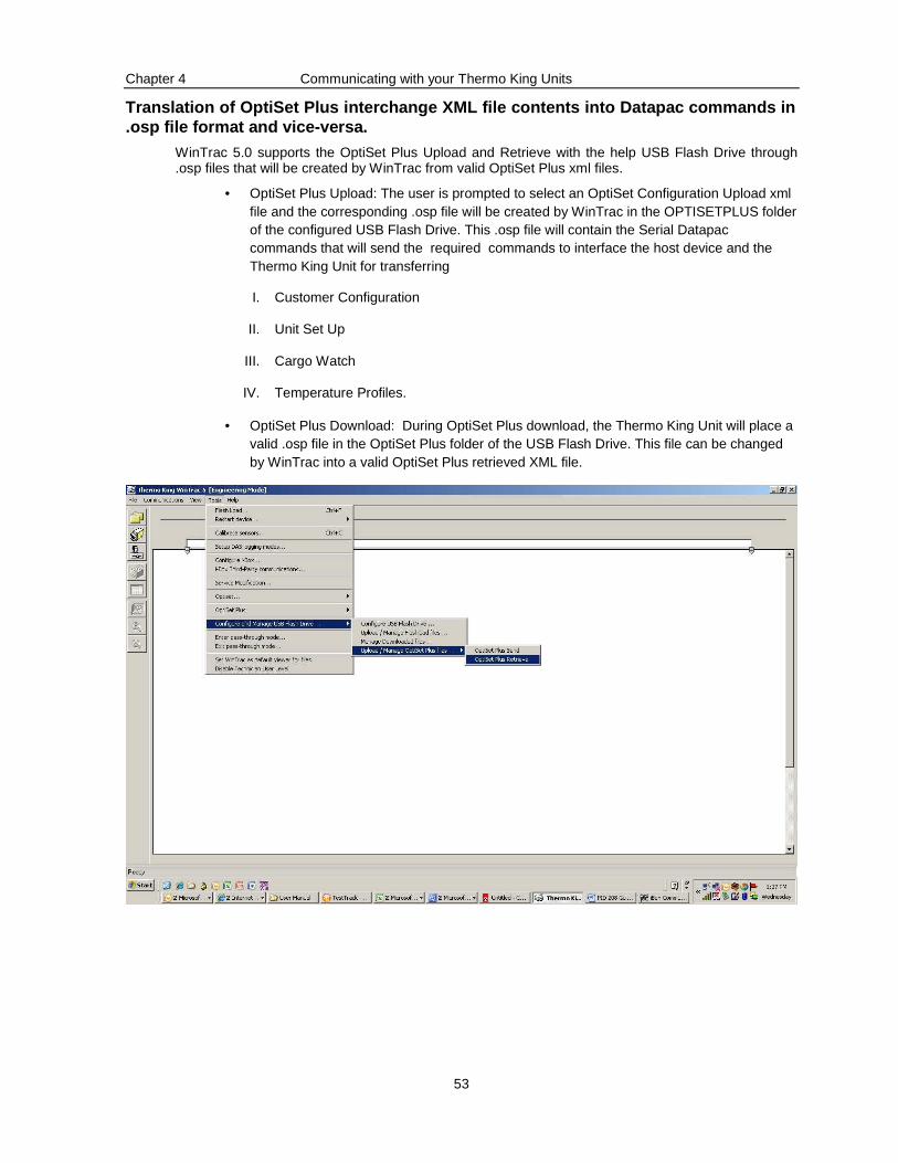
Chapter 4 Communicating with your Thermo King Units
53
Translation of OptiSet Plus interchange XML file co ntents into Datapac commands in .osp file format and vice-versa.
WinTrac 5.0 supports the OptiSet Plus Upload and Retrieve with the help USB Flash Drive through .osp files that will be created by WinTrac from valid OptiSet Plus xml files.
• OptiSet Plus Upload: The user is prompted to select an OptiSet Configuration Upload xml file and the corresponding .osp file will be created by WinTrac in the OPTISETPLUS folder of the configured USB Flash Drive. This .osp file will contain the Serial Datapac commands that will send the required commands to interface the host device and the Thermo King Unit for transferring
I. Customer Configuration
II. Unit Set Up
III. Cargo Watch
IV. Temperature Profiles.
• OptiSet Plus Download: During OptiSet Plus download, the Thermo King Unit will place a valid .osp file in the OptiSet Plus folder of the USB Flash Drive. This file can be changed by WinTrac into a valid OptiSet Plus retrieved XML file.
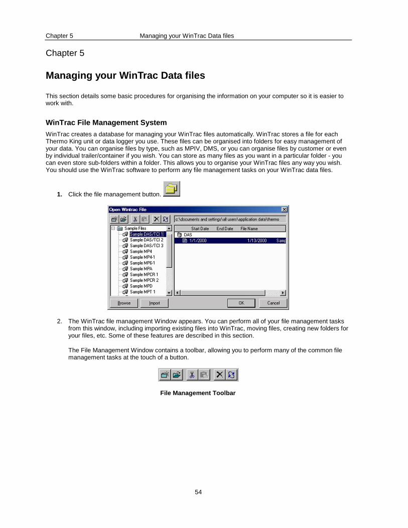
Chapter 5 Managing your WinTrac Data files
54
Chapter 5
Managing your WinTrac Data files
This section details some basic procedures for organising the information on your computer so it is easier to work with.
WinTrac File Management System
WinTrac creates a database for managing your WinTrac files automatically. WinTrac stores a file for each Thermo King unit or data logger you use. These files can be organised into folders for easy management of your data. You can organise files by type, such as MPIV, DMS, or you can organise files by customer or even by individual trailer/container if you wish. You can store as many files as you want in a particular folder - you can even store sub-folders within a folder. This allows you to organise your WinTrac files any way you wish. You should use the WinTrac software to perform any file management tasks on your WinTrac data files.
1. Click the file management button.
2. The WinTrac file management Window appears. You can perform all of your file management tasks from this window, including importing existing files into WinTrac, moving files, creating new folders for your files, etc. Some of these features are described in this section.
The File Management Window contains a toolbar, allowing you to perform many of the common file management tasks at the touch of a button.
File Management Toolbar
Chapter 5 Managing your WinTrac Data files
55
The New Folder button allows you to create a new folder for storing your WinTrac data files.
The Open Folder button expands a Folder, showing you the full contents of the folder.
The Cut button removes a file from its present location, and copies it to the Clipboard. You can then paste this file into another location within the WinTrac File System.
The Paste button copies a file from the Clipboard into the WinTrac file management system. Click on the folder where you wish to place the file before pasting it from the clipboard.
The Delete button deletes the currently selected file or folder from the WinTrac File System. Care should be taken when using this button since you can delete entire folders (including all files) from the WinTrac File System.
The Refresh button refreshes the File Management Window. You can refresh the File Management Window after you have performed some file management tasks, to see any changes that have occurred.
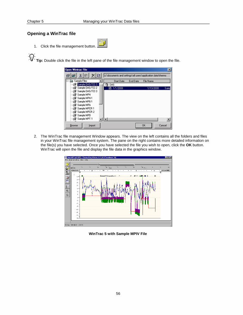
Chapter 5 Managing your WinTrac Data files
56
Opening a WinTrac file
1. Click the file management button.
Tip: Double click the file in the left pane of the file management window to open the file.
2. The WinTrac file management Window appears. The view on the left contains all the folders and files in your WinTrac file management system. The pane on the right contains more detailed information on the file(s) you have selected. Once you have selected the file you wish to open, click the OK button. WinTrac will open the file and display the file data in the graphics window.
WinTrac 5 with Sample MPIV File
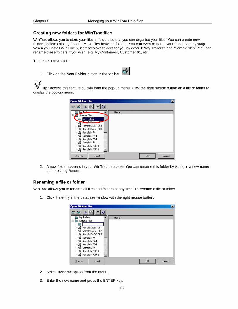
Chapter 5 Managing your WinTrac Data files
57
Creating new folders for WinTrac files
WinTrac allows you to store your files in folders so that you can organise your files. You can create new folders, delete existing folders, Move files between folders. You can even re-name your folders at any stage. When you install WinTrac 5, it creates two folders for you by default: “My Trailers”, and “Sample files”. You can rename these folders if you wish, e.g. My Containers, Customer 01, etc.
To create a new folder
1. Click on the New Folder button in the toolbar.
Tip: Access this feature quickly from the pop-up menu. Click the right mouse button on a file or folder to display the pop-up menu.
2. A new folder appears in your WinTrac database. You can rename this folder by typing in a new name and pressing Return.
Renaming a file or folder
WinTrac allows you to rename all files and folders at any time. To rename a file or folder
1. Click the entry in the database window with the right mouse button.
2. Select Rename option from the menu.
3. Enter the new name and press the ENTER key.
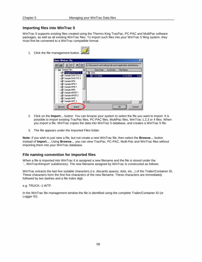
Chapter 5 Managing your WinTrac Data files
58
Importing files into WinTrac 5
WinTrac 5 supports existing files created using the Thermo King TracPac, PC-PAC and MultiPac software packages, as well as all existing WinTrac files. To import such files into your WinTrac 5 filing system, they must first be converted to a WinTrac compatible format.
1. Click the file management button.
2. Click on the Import… button. You can browse your system to select the file you want to import. It is possible to import existing TracPac files, PC-PAC files, MultiPac files, WinTrac 1,2,3 or 4 files. When you import a file, WinTrac copies the data into WinTrac 5 database, and creates a WinTrac 5 file.
3. The file appears under the Imported Files folder.
Note: If you wish to just view a file, but not create a new WinTrac file, then select the Browse… button instead of Import… . Using Browse… you can view TracPac, PC-PAC, Multi-Pac and WinTrac files without importing them into your WinTrac database.
File naming convention for imported files
When a file is imported into WinTrac it is assigned a new filename and the file is stored under the ‘…WinTrac4\Import’ subdirectory. The new filename assigned by WinTrac is constructed as follows:
WinTrac extracts the last five suitable characters (i.e. discards spaces, dots, etc...) of the Trailer/Container ID. These characters form the first five characters of the new filename. These characters are immediately followed by two dashes and a file index digit.
e.g. TRUCK--1.WTF.
In the WinTrac file management window the file is identified using the complete Trailer/Container ID (or Logger ID).
Chapter 5 Managing your WinTrac Data files
59
Moving a file or folder
Once you have created WinTrac files or folders you can move around the files and folders to suit your needs. You can also delete files or folders if they are no longer needed.
Tip: Alternatively drag the folder or file to its new location using the mouse.
To move a file or folder the WinTrac filing system:
1. Select the file (or folder) you wish to move by clicking on it.
2. Click the Cut button. This removes the file from its current location and store it in memory.
3. Click on the Folder where you wish to place the file. Then click on the Paste button. The file will then
be copied to the new location.
Tip: Access this feature quickly from the pop-up menu. Click the right mouse button on a file or folder to display the pop-up menu.
Deleting a file or folder
To delete a file or folder from the WinTrac filing system:
1. Select the file (or folder) you wish to delete by clicking on it.
Press the Delete button. This deletes the file (or folder) from its current location. Care should be taken when
using this feature since you can delete entire folders (including all files) using the Delete button!
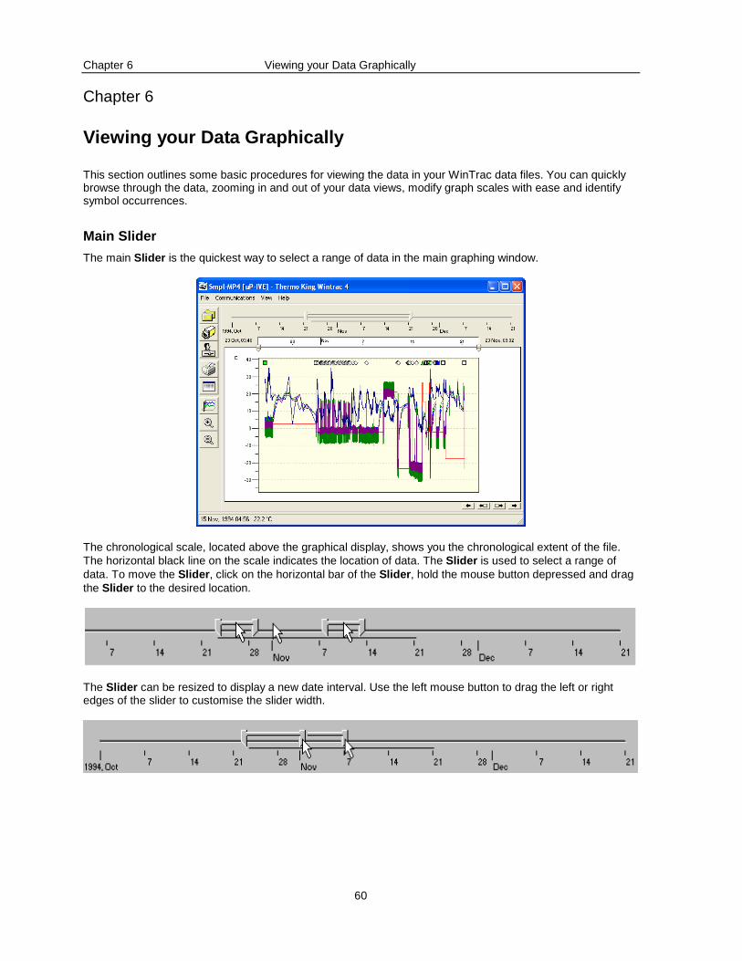
Chapter 6 Viewing your Data Graphically
60
Chapter 6
Viewing your Data Graphically
This section outlines some basic procedures for viewing the data in your WinTrac data files. You can quickly browse through the data, zooming in and out of your data views, modify graph scales with ease and identify symbol occurrences.
Main Slider
The main Slider is the quickest way to select a range of data in the main graphing window.
The chronological scale, located above the graphical display, shows you the chronological extent of the file. The horizontal black line on the scale indicates the location of data. The Slider is used to select a range of data. To move the Slider , click on the horizontal bar of the Slider , hold the mouse button depressed and drag the Slider to the desired location.
The Slider can be resized to display a new date interval. Use the left mouse button to drag the left or right edges of the slider to customise the slider width.
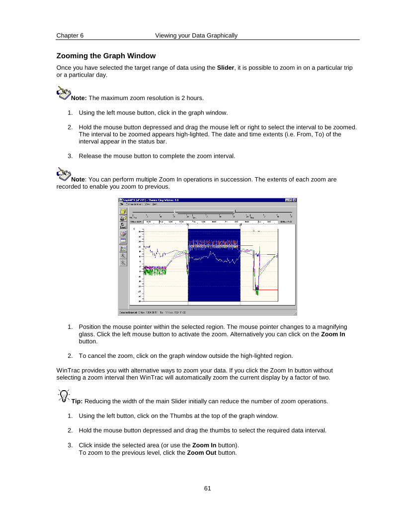
Chapter 6 Viewing your Data Graphically
61
Zooming the Graph Window
Once you have selected the target range of data using the Slider , it is possible to zoom in on a particular trip or a particular day.
Note: The maximum zoom resolution is 2 hours.
1. Using the left mouse button, click in the graph window.
2. Hold the mouse button depressed and drag the mouse left or right to select the interval to be zoomed. The interval to be zoomed appears high-lighted. The date and time extents (i.e. From, To) of the interval appear in the status bar.
3. Release the mouse button to complete the zoom interval.
Note : You can perform multiple Zoom In operations in succession. The extents of each zoom are recorded to enable you zoom to previous.
1. Position the mouse pointer within the selected region. The mouse pointer changes to a magnifying glass. Click the left mouse button to activate the zoom. Alternatively you can click on the Zoom In button.
2. To cancel the zoom, click on the graph window outside the high-lighted region.
WinTrac provides you with alternative ways to zoom your data. If you click the Zoom In button without selecting a zoom interval then WinTrac will automatically zoom the current display by a factor of two.
Tip: Reducing the width of the main Slider initially can reduce the number of zoom operations.
1. Using the left button, click on the Thumbs at the top of the graph window.
2. Hold the mouse button depressed and drag the thumbs to select the required data interval.
3. Click inside the selected area (or use the Zoom In button). To zoom to the previous level, click the Zoom Out button.
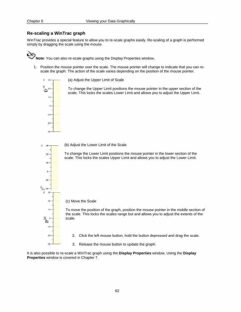
Chapter 6 Viewing your Data Graphically
62
Re-scaling a WinTrac graph
WinTrac provides a special feature to allow you to re-scale graphs easily. Re-scaling of a graph is performed simply by dragging the scale using the mouse.
Note : You can also re-scale graphs using the Display Properties window.
1. Position the mouse pointer over the scale. The mouse pointer will change to indicate that you can re-scale the graph. The action of the scale varies depending on the position of the mouse pointer.
(a) Adjust the Upper Limit of Scale
To change the Upper Limit positions the mouse pointer in the upper section of the scale. This locks the scales Lower Limit and allows you to adjust the Upper Limit.
(b) Adjust the Lower Limit of the Scale
To change the Lower Limit positions the mouse pointer in the lower section of the scale. This locks the scales Upper Limit and allows you to adjust the Lower Limit.
(c) Move the Scale
To move the position of the graph, position the mouse pointer in the middle section of the scale. This locks the scales range but and allows you to adjust the extents of the scale.
2. Click the left mouse button, hold the button depressed and drag the scale.
3. Release the mouse button to update the graph.
It is also possible to re-scale a WinTrac graph using the Display Properties window. Using the Display Properties window is covered in Chapter 7.
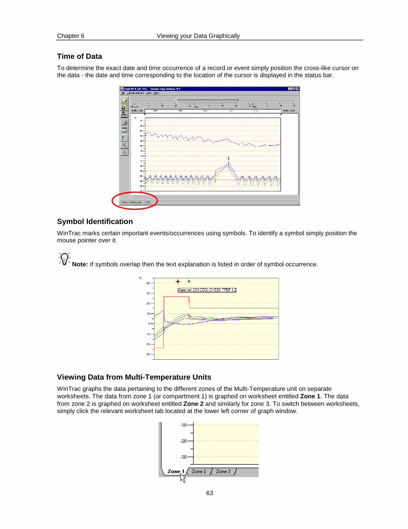
Chapter 6 Viewing your Data Graphically
63
Time of Data
To determine the exact date and time occurrence of a record or event simply position the cross-like cursor on the data - the date and time corresponding to the location of the cursor is displayed in the status bar.
Symbol Identification
WinTrac marks certain important events/occurrences using symbols. To identify a symbol simply position the mouse pointer over it.
Note: If symbols overlap then the text explanation is listed in order of symbol occurrence.
Viewing Data from Multi-Temperature Units
WinTrac graphs the data pertaining to the different zones of the Multi-Temperature unit on separate worksheets. The data from zone 1 (or compartment 1) is graphed on worksheet entitled Zone 1 . The data from zone 2 is graphed on worksheet entitled Zone 2 and similarly for zone 3. To switch between worksheets, simply click the relevant worksheet tab located at the lower left corner of graph window.
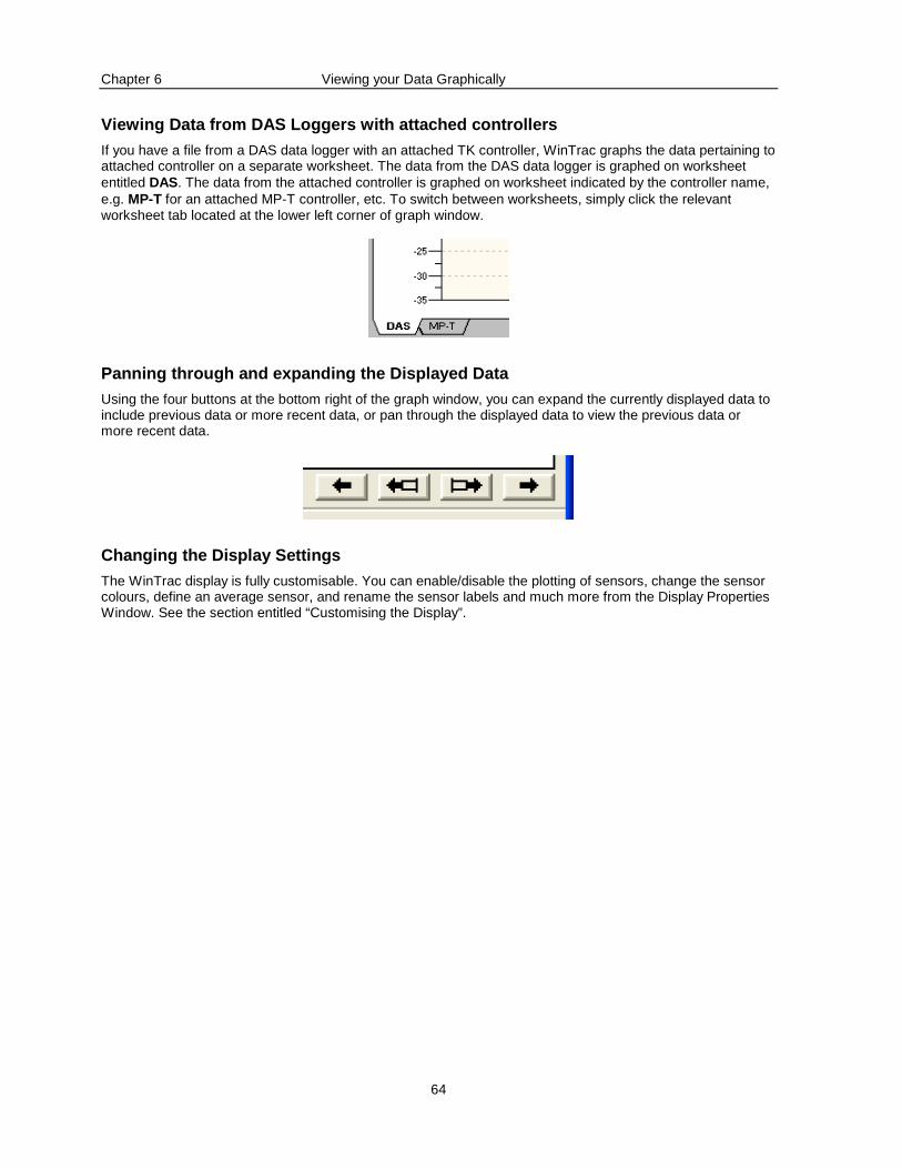
Chapter 6 Viewing your Data Graphically
64
Viewing Data from DAS Loggers with attached control lers
If you have a file from a DAS data logger with an attached TK controller, WinTrac graphs the data pertaining to attached controller on a separate worksheet. The data from the DAS data logger is graphed on worksheet entitled DAS. The data from the attached controller is graphed on worksheet indicated by the controller name, e.g. MP-T for an attached MP-T controller, etc. To switch between worksheets, simply click the relevant worksheet tab located at the lower left corner of graph window.
Panning through and expanding the Displayed Data
Using the four buttons at the bottom right of the graph window, you can expand the currently displayed data to include previous data or more recent data, or pan through the displayed data to view the previous data or more recent data.
Changing the Display Settings
The WinTrac display is fully customisable. You can enable/disable the plotting of sensors, change the sensor colours, define an average sensor, and rename the sensor labels and much more from the Display Properties Window. See the section entitled “Customising the Display”.
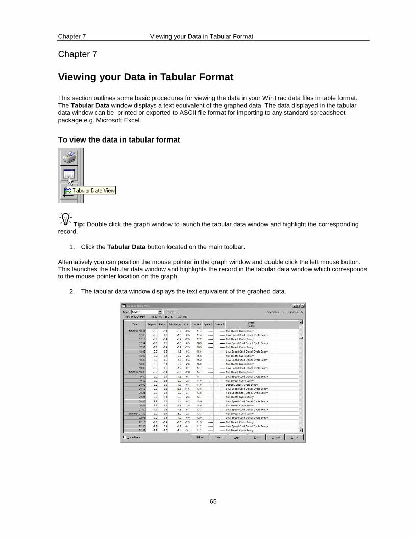
Chapter 7 Viewing your Data in Tabular Format
65
Chapter 7
Viewing your Data in Tabular Format
This section outlines some basic procedures for viewing the data in your WinTrac data files in table format. The Tabular Data window displays a text equivalent of the graphed data. The data displayed in the tabular data window can be printed or exported to ASCII file format for importing to any standard spreadsheet package e.g. Microsoft Excel.
To view the data in tabular format
Tip: Double click the graph window to launch the tabular data window and highlight the corresponding record.
1. Click the Tabular Data button located on the main toolbar.
Alternatively you can position the mouse pointer in the graph window and double click the left mouse button. This launches the tabular data window and highlights the record in the tabular data window which corresponds to the mouse pointer location on the graph.
2. The tabular data window displays the text equivalent of the graphed data.
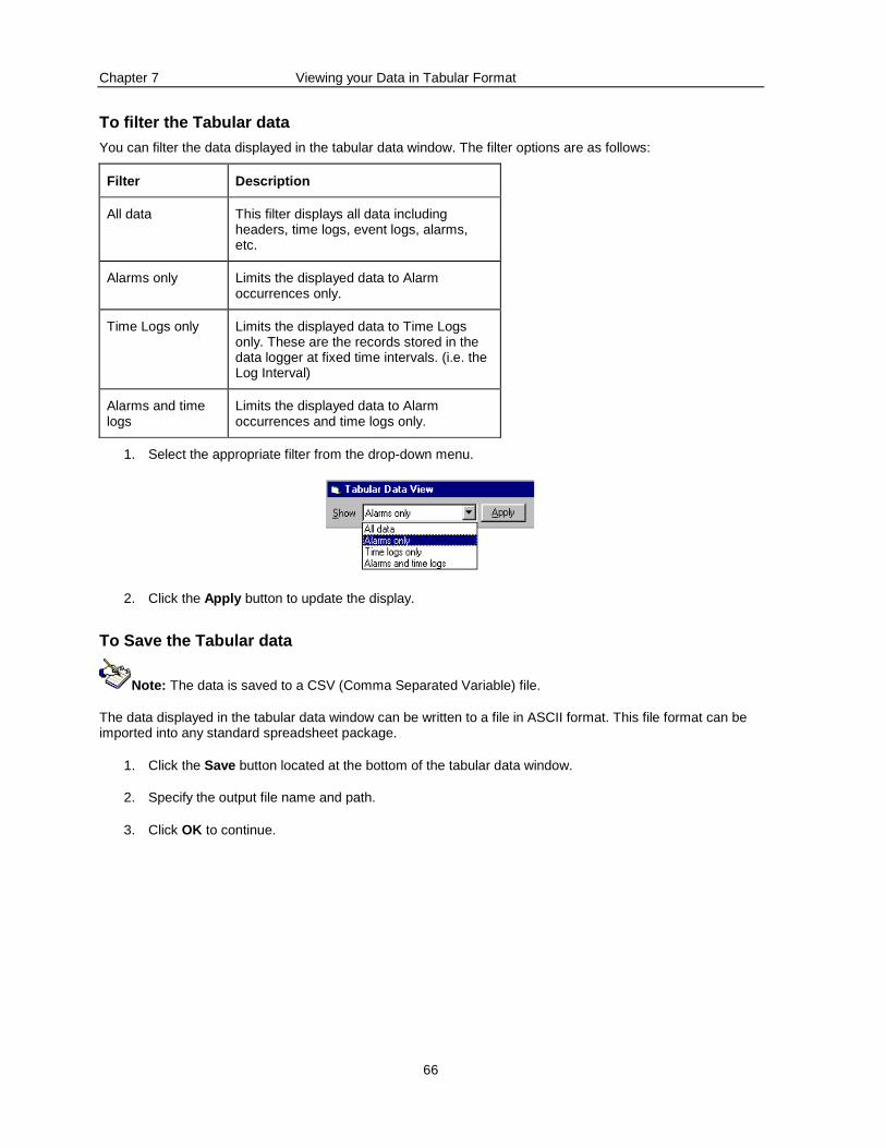
Chapter 7 Viewing your Data in Tabular Format
66
To filter the Tabular data
You can filter the data displayed in the tabular data window. The filter options are as follows:
Filter Description
All data This filter displays all data including headers, time logs, event logs, alarms, etc.
Alarms only Limits the displayed data to Alarm occurrences only.
Time Logs only Limits the displayed data to Time Logs only. These are the records stored in the data logger at fixed time intervals. (i.e. the Log Interval)
Alarms and time logs
Limits the displayed data to Alarm occurrences and time logs only.
1. Select the appropriate filter from the drop-down menu.
2. Click the Apply button to update the display.
To Save the Tabular data
Note: The data is saved to a CSV (Comma Separated Variable) file.
The data displayed in the tabular data window can be written to a file in ASCII format. This file format can be imported into any standard spreadsheet package.
1. Click the Save button located at the bottom of the tabular data window.
2. Specify the output file name and path.
3. Click OK to continue.
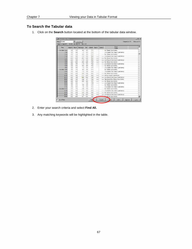
Chapter 7 Viewing your Data in Tabular Format
67
To Search the Tabular data
1. Click on the Search button located at the bottom of the tabular data window.
2. Enter your search criteria and select Find All.
3. Any matching keywords will be highlighted in the table.
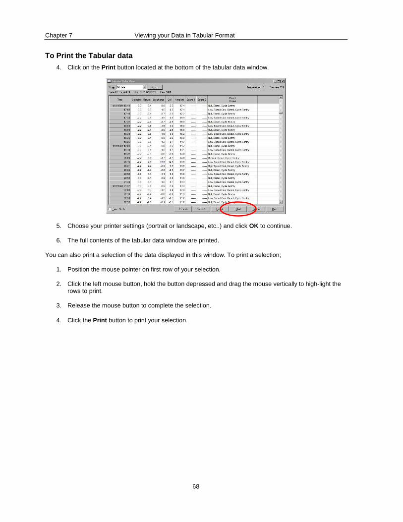
Chapter 7 Viewing your Data in Tabular Format
68
To Print the Tabular data
4. Click on the Print button located at the bottom of the tabular data window.
5. Choose your printer settings (portrait or landscape, etc..) and click OK to continue.
6. The full contents of the tabular data window are printed.
You can also print a selection of the data displayed in this window. To print a selection;
1. Position the mouse pointer on first row of your selection.
2. Click the left mouse button, hold the button depressed and drag the mouse vertically to high-light the rows to print.
3. Release the mouse button to complete the selection.
4. Click the Print button to print your selection.
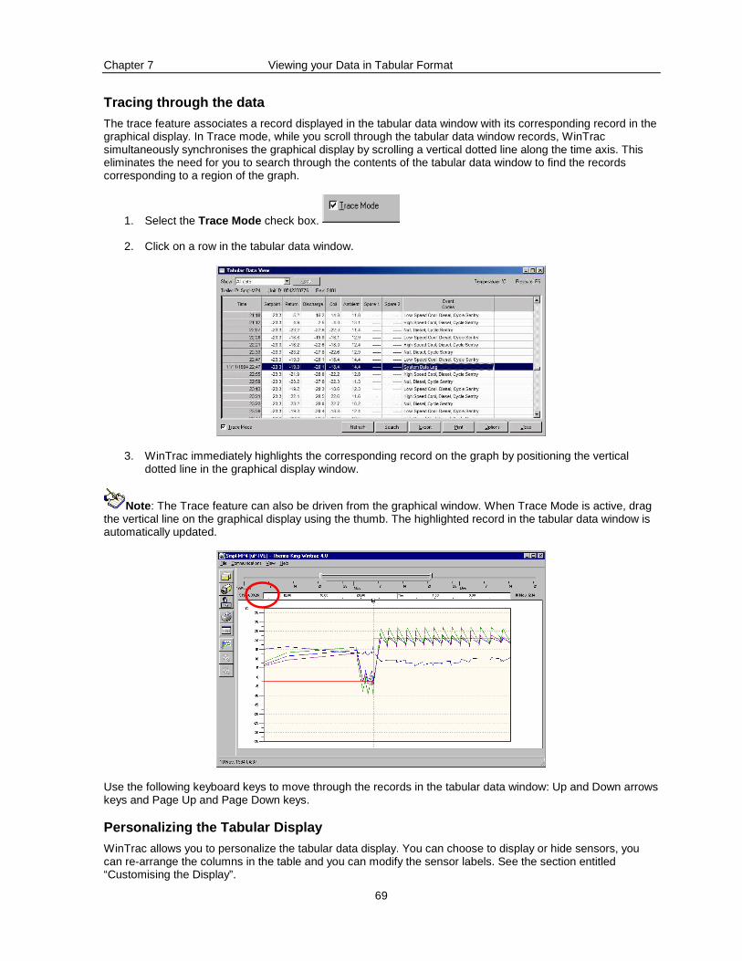
Chapter 7 Viewing your Data in Tabular Format
69
Tracing through the data
The trace feature associates a record displayed in the tabular data window with its corresponding record in the graphical display. In Trace mode, while you scroll through the tabular data window records, WinTrac simultaneously synchronises the graphical display by scrolling a vertical dotted line along the time axis. This eliminates the need for you to search through the contents of the tabular data window to find the records corresponding to a region of the graph.
1. Select the Trace Mode check box.
2. Click on a row in the tabular data window.
3. WinTrac immediately highlights the corresponding record on the graph by positioning the vertical dotted line in the graphical display window.
Note : The Trace feature can also be driven from the graphical window. When Trace Mode is active, drag the vertical line on the graphical display using the thumb. The highlighted record in the tabular data window is automatically updated.
Use the following keyboard keys to move through the records in the tabular data window: Up and Down arrows keys and Page Up and Page Down keys.
Personalizing the Tabular Display
WinTrac allows you to personalize the tabular data display. You can choose to display or hide sensors, you can re-arrange the columns in the table and you can modify the sensor labels. See the section entitled “Customising the Display”.
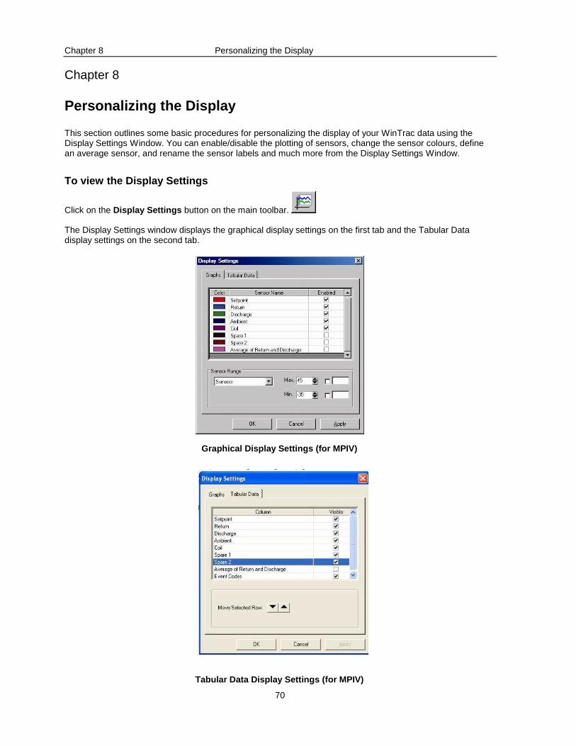
Chapter 8 Personalizing the Display
70
Chapter 8
Personalizing the Display
This section outlines some basic procedures for personalizing the display of your WinTrac data using the Display Settings Window. You can enable/disable the plotting of sensors, change the sensor colours, define an average sensor, and rename the sensor labels and much more from the Display Settings Window.
To view the Display Settings
Click on the Display Settings button on the main toolbar.
The Display Settings window displays the graphical display settings on the first tab and the Tabular Data display settings on the second tab.
Graphical Display Settings (for MPIV)
Tabular Data Display Settings (for MPIV)
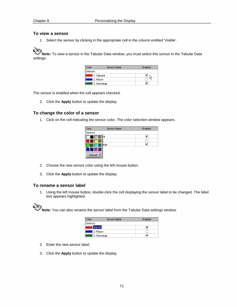
Chapter 8 Personalizing the Display
71
To view a sensor
1. Select the sensor by clicking in the appropriate cell in the column entitled ‘Visible’.
Note: To view a sensor in the Tabular Data window, you must select this sensor in the Tabular Data settings.
The sensor is enabled when the cell appears checked.
2. Click the Apply button to update the display.
To change the color of a sensor
1. Click on the cell indicating the sensor color. The color selection window appears.
2. Choose the new sensor color using the left mouse button.
3. Click the Apply button to update the display.
To rename a sensor label
1. Using the left mouse button, double-click the cell displaying the sensor label to be changed. The label text appears highlighted.
Note: You can also rename the sensor label from the Tabular Data settings window.
2. Enter the new sensor label.
3. Click the Apply button to update the display.
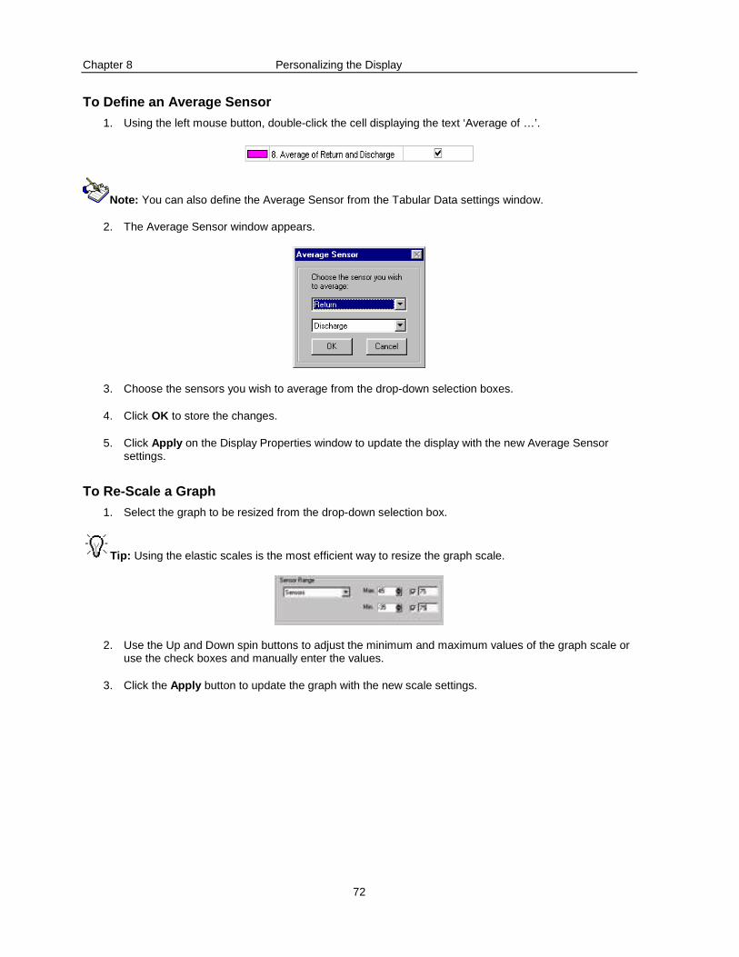
Chapter 8 Personalizing the Display
72
To Define an Average Sensor
1. Using the left mouse button, double-click the cell displaying the text ‘Average of …’.
Note: You can also define the Average Sensor from the Tabular Data settings window.
2. The Average Sensor window appears.
3. Choose the sensors you wish to average from the drop-down selection boxes.
4. Click OK to store the changes.
5. Click Apply on the Display Properties window to update the display with the new Average Sensor settings.
To Re-Scale a Graph
1. Select the graph to be resized from the drop-down selection box.
Tip: Using the elastic scales is the most efficient way to resize the graph scale.
2. Use the Up and Down spin buttons to adjust the minimum and maximum values of the graph scale or use the check boxes and manually enter the values.
3. Click the Apply button to update the graph with the new scale settings.
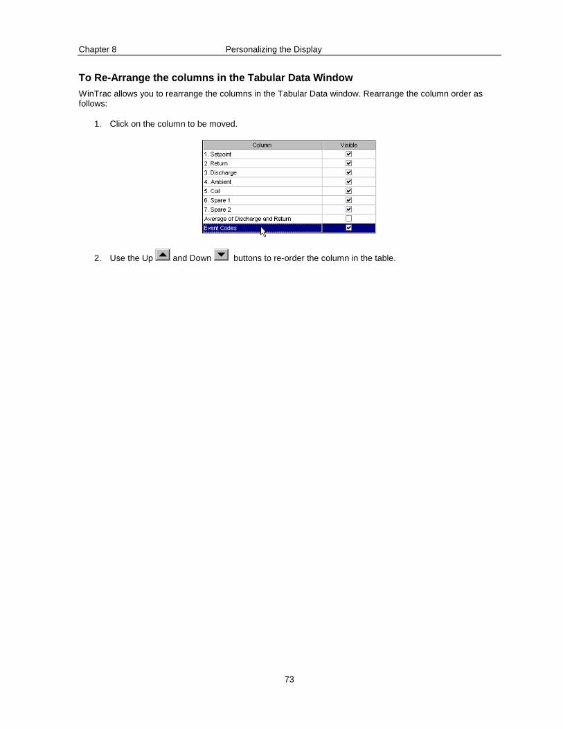
Chapter 8 Personalizing the Display
73
To Re-Arrange the columns in the Tabular Data Windo w
WinTrac allows you to rearrange the columns in the Tabular Data window. Rearrange the column order as follows:
1. Click on the column to be moved.
2. Use the Up and Down buttons to re-order the column in the table.
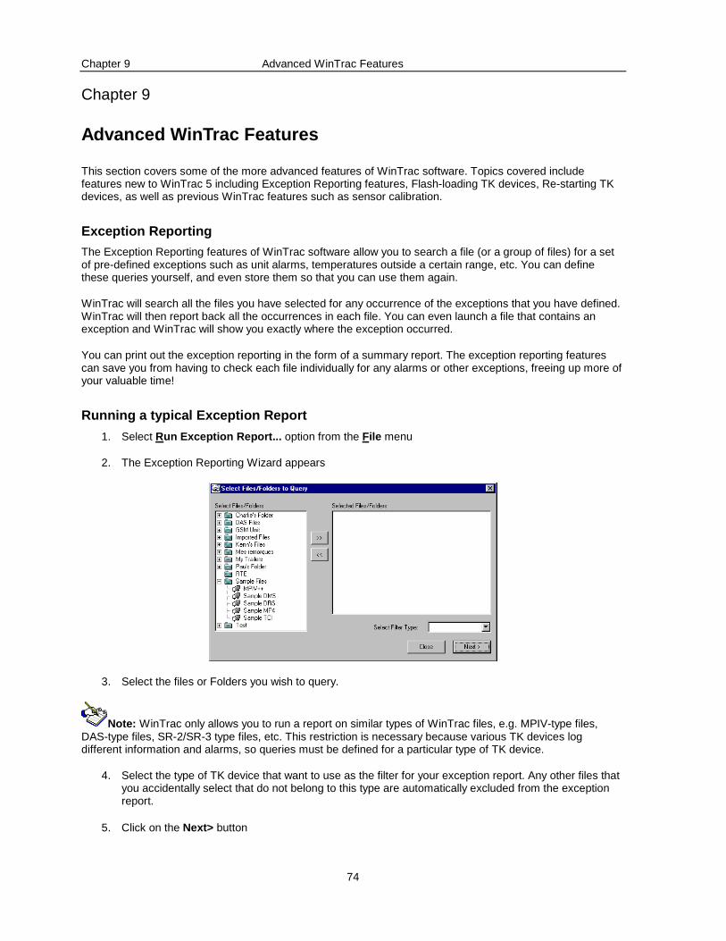
Chapter 9 Advanced WinTrac Features
74
Chapter 9
Advanced WinTrac Features
This section covers some of the more advanced features of WinTrac software. Topics covered include features new to WinTrac 5 including Exception Reporting features, Flash-loading TK devices, Re-starting TK devices, as well as previous WinTrac features such as sensor calibration.
Exception Reporting
The Exception Reporting features of WinTrac software allow you to search a file (or a group of files) for a set of pre-defined exceptions such as unit alarms, temperatures outside a certain range, etc. You can define these queries yourself, and even store them so that you can use them again.
WinTrac will search all the files you have selected for any occurrence of the exceptions that you have defined. WinTrac will then report back all the occurrences in each file. You can even launch a file that contains an exception and WinTrac will show you exactly where the exception occurred.
You can print out the exception reporting in the form of a summary report. The exception reporting features can save you from having to check each file individually for any alarms or other exceptions, freeing up more of your valuable time!
Running a typical Exception Report
1. Select Run Exception Report... option from the File menu
2. The Exception Reporting Wizard appears
3. Select the files or Folders you wish to query.
Note: WinTrac only allows you to run a report on similar types of WinTrac files, e.g. MPIV-type files, DAS-type files, SR-2/SR-3 type files, etc. This restriction is necessary because various TK devices log different information and alarms, so queries must be defined for a particular type of TK device.
4. Select the type of TK device that want to use as the filter for your exception report. Any other files that you accidentally select that do not belong to this type are automatically excluded from the exception report.
5. Click on the Next> button
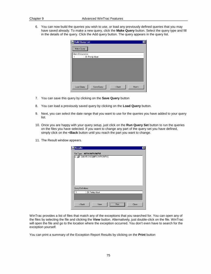
Chapter 9 Advanced WinTrac Features
75
6. You can now build the queries you wish to use, or load any previously defined queries that you may have saved already. To make a new query, click the Make Query button. Select the query type and fill in the details of the query. Click the Add query button. The query appears in the query list.
7. You can save this query by clicking on the Save Query button
8. You can load a previously saved query by clicking on the Load Query button.
9. Next, you can select the date range that you want to use for the queries you have added to your query list.
10. Once you are happy with your query setup, just click on the Run Query Set button to run the queries on the files you have selected. If you want to change any part of the query set you have defined, simply click on the <Back button until you reach the part you want to change.
11. The Result window appears.
WinTrac provides a list of files that match any of the exceptions that you searched for. You can open any of the files by selecting the file and clicking the View button. Alternatively, just double-click on the file. WinTrac will open the file and go to the location where the exception occurred. You don’t even have to search for the exception yourself.
You can print a summary of the Exception Report Results by clicking on the Print button
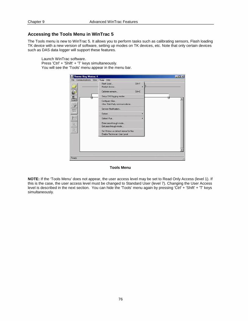
Chapter 9 Advanced WinTrac Features
76
Accessing the Tools Menu in WinTrac 5
The Tools menu is new to WinTrac 5. It allows you to perform tasks such as calibrating sensors, Flash loading TK device with a new version of software, setting up modes on TK devices, etc. Note that only certain devices such as DAS data logger will support these features.
Launch WinTrac software. Press 'Ctrl' + 'Shift' + 'T' keys simultaneously. You will see the 'Tools' menu appear in the menu bar.
Tools Menu
NOTE: If the ‘Tools Menu’ does not appear, the user access level may be set to Read Only Access (level 1). If this is the case, the user access level must be changed to Standard User (level 7). Changing the User Access level is described in the next section. You can hide the 'Tools' menu again by pressing 'Ctrl' + 'Shift' + 'T' keys simultaneously.
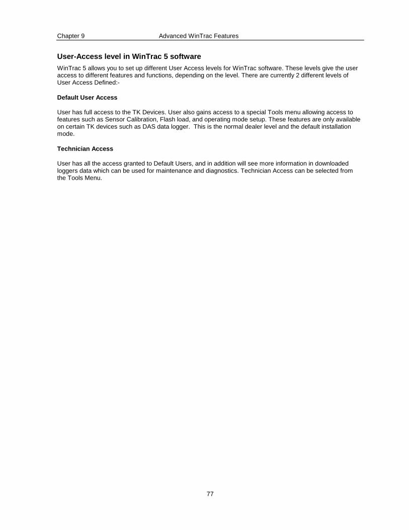
Chapter 9 Advanced WinTrac Features
77
User-Access level in WinTrac 5 software
WinTrac 5 allows you to set up different User Access levels for WinTrac software. These levels give the user access to different features and functions, depending on the level. There are currently 2 different levels of User Access Defined:-
Default User Access
User has full access to the TK Devices. User also gains access to a special Tools menu allowing access to features such as Sensor Calibration, Flash load, and operating mode setup. These features are only available on certain TK devices such as DAS data logger. This is the normal dealer level and the default installation mode.
Technician Access
User has all the access granted to Default Users, and in addition will see more information in downloaded loggers data which can be used for maintenance and diagnostics. Technician Access can be selected from the Tools Menu.
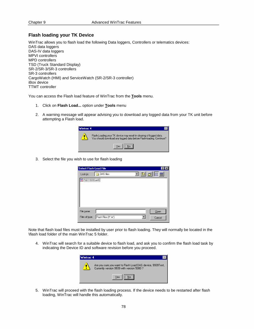
Chapter 9 Advanced WinTrac Features
78
Flash loading your TK Device
WinTrac allows you to flash load the following Data loggers, Controllers or telematics devices: DAS data loggers DAS-IV data loggers MPVI controllers MPD controllers TSD (Truck Standard Display) SR-2/SR-3/SR-3 controllers SR-3 controllers CargoWatch (HMI) and ServiceWatch (SR-2/SR-3 controller) iBox device TTMT controller
You can access the Flash load feature of WinTrac from the Tools menu.
1. Click on Flash Load... option under Tools menu
2. A warning message will appear advising you to download any logged data from your TK unit before attempting a Flash load.
3. Select the file you wish to use for flash loading
Note that flash load files must be installed by user prior to flash loading. They will normally be located in the \flash load folder of the main WinTrac 5 folder.
4. WinTrac will search for a suitable device to flash load, and ask you to confirm the flash load task by indicating the Device ID and software revision before you proceed.
5. WinTrac will proceed with the flash loading process. If the device needs to be restarted after flash loading, WinTrac will handle this automatically.

Chapter 9 Advanced WinTrac Features
79
6. WinTrac informs you that flash loading has completed successfully.
If the flash loading process fails, WinTrac will prompt you to re-try. You should check all power and communications connections before re-trying as this may have led to the flash load failure.
If Flash load re-try still fails, try powering down your device and powering it up again before retrying. This may help WinTrac to find the device when starting the flash load process.
Calibrating Sensors
You can calibrate the Sensors on your DMS or DAS data loggers using WinTrac software. Sensor calibration on DMS loggers is normally performed using ice-bath calibration, but you can choose either ice-bath calibration or sensor-grade calibration for your DAS data logger.
Ice-bath Calibration
1. Place the sensor you wish to calibrate in an ice-bath, until the temperature reads 0°C (32°F).
2. Select the Calibrate sensors… option under the Tools menu. The sensor calibration window appears.
3. Select the sensor you wish to calibrate, select ice-bath calibration and click on the Calibrate… button. WinTrac will calibrate the sensor and inform you when calibration is complete. If the Sensor reading is too far from 0°C (32°F), then WinTrac will inform y ou that the chosen sensor is out of range. This also prevents the accidental calibration of a different sensor.
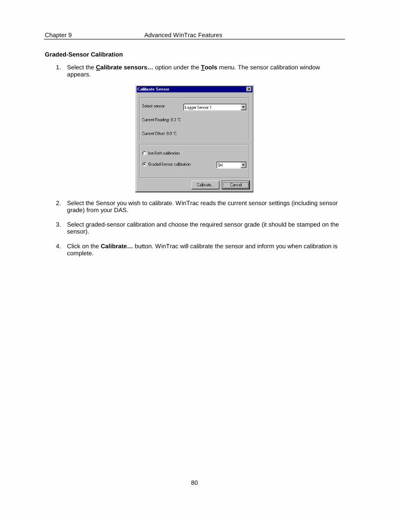
Chapter 9 Advanced WinTrac Features
80
Graded-Sensor Calibration
1. Select the Calibrate sensors… option under the Tools menu. The sensor calibration window appears.
2. Select the Sensor you wish to calibrate. WinTrac reads the current sensor settings (including sensor grade) from your DAS.
3. Select graded-sensor calibration and choose the required sensor grade (it should be stamped on the sensor).
4. Click on the Calibrate… button. WinTrac will calibrate the sensor and inform you when calibration is complete.
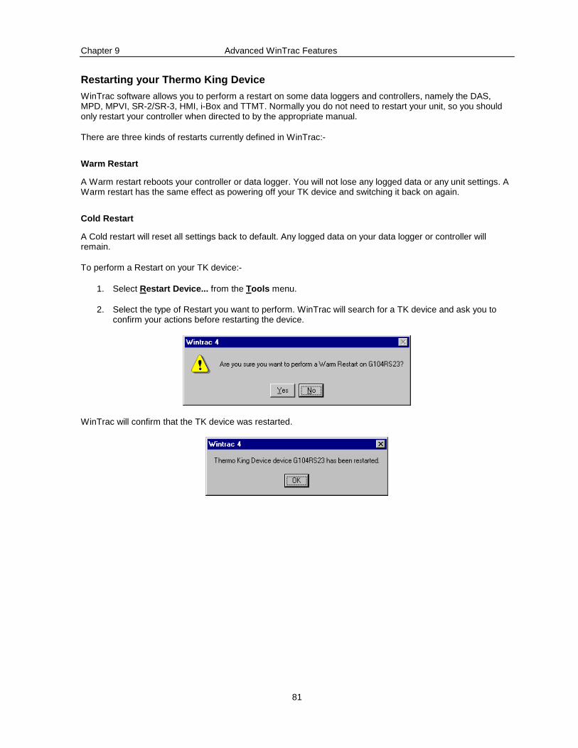
Chapter 9 Advanced WinTrac Features
81
Restarting your Thermo King Device
WinTrac software allows you to perform a restart on some data loggers and controllers, namely the DAS, MPD, MPVI, SR-2/SR-3, HMI, i-Box and TTMT. Normally you do not need to restart your unit, so you should only restart your controller when directed to by the appropriate manual.
There are three kinds of restarts currently defined in WinTrac:-
Warm Restart
A Warm restart reboots your controller or data logger. You will not lose any logged data or any unit settings. A Warm restart has the same effect as powering off your TK device and switching it back on again.
Cold Restart
A Cold restart will reset all settings back to default. Any logged data on your data logger or controller will remain.
To perform a Restart on your TK device:-
1. Select Restart Device... from the Tools menu.
2. Select the type of Restart you want to perform. WinTrac will search for a TK device and ask you to confirm your actions before restarting the device.
WinTrac will confirm that the TK device was restarted.
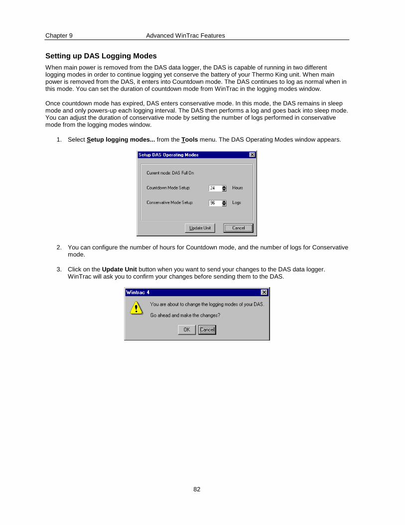
Chapter 9 Advanced WinTrac Features
82
Setting up DAS Logging Modes
When main power is removed from the DAS data logger, the DAS is capable of running in two different logging modes in order to continue logging yet conserve the battery of your Thermo King unit. When main power is removed from the DAS, it enters into Countdown mode. The DAS continues to log as normal when in this mode. You can set the duration of countdown mode from WinTrac in the logging modes window.
Once countdown mode has expired, DAS enters conservative mode. In this mode, the DAS remains in sleep mode and only powers-up each logging interval. The DAS then performs a log and goes back into sleep mode. You can adjust the duration of conservative mode by setting the number of logs performed in conservative mode from the logging modes window.
1. Select Setup logging modes... from the Tools menu. The DAS Operating Modes window appears.
2. You can configure the number of hours for Countdown mode, and the number of logs for Conservative mode.
3. Click on the Update Unit button when you want to send your changes to the DAS data logger. WinTrac will ask you to confirm your changes before sending them to the DAS.
Chapter 9 Advanced WinTrac Features
83
Using OptiSet Feature of TK Controllers
NOTE: For OptiSet Plus™ features see the following section “Using OptiSet Plus Feature of TK Controllers”.
OptiSet configuration can be accomplished using the new “OptiSet Setup Guide" program provided on the WinTrac 5 CD-ROM in the "OptiSet" folder. The "OptiSet Setup Guide" program can also be downloaded from The Thermo King Internet site on the World Wide Web. This program steps the user through the configuration of various Temperature "ranges". Within each of these ranges, the user can pre-determine and set all the various unit modes and run options. There are up to ten ranges available (0-9) that can be pre-set by the user. Once these ranges are setup, the program displays a "Create Upload File" button in the bottom left corner of the "Range Setup" screen. Clicking on this button will create the actual upload file. Users have the option of naming and saving this upload file anywhere on their PC with this option. It is this upload file that WinTrac 5 will use to update the controller on a Thermo King unit.
Sending/Uploading OptiSet Configuration to a Contro ller
After you have created a .CSV format file using the "OptiSet Setup Guide" program, you can use WinTrac to upload the file into the controller. To accomplish this, you will be using the new "Send OptiSet Configuration..." option from the "Tools" menu in WinTrac. The "Tools" menu item is a secure function. If you need to perform an upload and do not have the "Tools" menu option showing, please read the Section entitled “Accessing the Tools menu in WinTrac 5”. WinTrac will ask you for the name of the configuration file you wish to send to the controller. Once the upload file is identified, WinTrac checks the unit connections and if they are valid will send the OptiSet configuration data to the controller and reset it with the new ranges and run selections. Once OptiSet has been loaded, simply changing the "SETPOINT" temperature on the unit keypad enables all of the unit run selections for that temperature.
Retrieving the current OptiSet Configuration from a Controller
You can also retrieve the current OptiSet configuration from your controller, and save it on your PC in the form of an .OPT file. This .OPT file can opened using the Thermo King "OptiSet Setup Guide" program. Simply select the "Retrieve OptiSet Configuration..." option from the "Tools" menu and follow the on-screen instructions. WinTrac creates a file suitable for opening in the "OptiSet Setup Guide" program. This function is useful for validating and saving a unit’s current OptiSet configuration prior to making changes.
Using OptiSet™ Plus Feature of TK Controllers
NOTE: For OptiSet features applicable to earlier controller versions see the previous section “Using OptiSet Feature of TK Controllers”.
OptiSet™ Plus provides custom temperature control based on particular commodities. The set of temperature control parameters for a given commodity is called a temperature profile. See the documentation on Thermo King's separate OptiSet Plus PC application for information on creating temperature profiles. The OptiSet Plus PC application produces a file called an interchange file that can be uploaded into the Thermo King Temperature Refrigeration Unit with WinTrac.
Sending/Uploading OptiSet Plus Configuration to a C ontroller
To send an interchange file use the "Send OptiSet Plus Configuration..." option from the "Tools" menu. WinTrac will ask you for the name of the interchange file to send to the refrigeration unit. WinTrac will check to ensure that the interchange file being uploaded is suitable for the target system.
Retrieving the current OptiSet Configuration from a Controller
You can retrieve the current OptiSet Plus configuration from your controller, and save it on your PC in a file that can be opened using the OptiSet Plus PC application. Simply select the "Retrieve OptiSet Plus Configuration..." option from the "Tools" menu and follow the on-screen instructions. This function is useful for validating and saving a unit's current OptiSet Plus configuration prior to making changes.
Chapter 9 Advanced WinTrac Features
84
Using Service Modification feature on Thermo King U nits
Units based on Thermo Kings Global Data Table (DAS, HMI, i-Box, SR-2/SR-33 etc.) can be directly configured from WinTrac using the Service Modification facility. Use of the Service Modification feature may alter the operation of the Thermo King refrigeration unit. We recommend this feature be used by trained TK Service Personnel only.
A .CSV format file containing the desired settings can be uploaded into the unit. To accomplish this, select the "Service Modification..." option from the "Tools" menu in WinTrac. The "Tools" menu item is a secure function. If you need to perform a modification and do not have the "Tools" menu option showing, please read the Section entitled “Accessing the Tools menu in WinTrac 5”. WinTrac will ask you for the name of the modification file you wish to send to the unit. Once the file is selected, WinTrac checks the connections to the unit and if they are valid will send the modification data to the unit and check the changes were accepted.
Using pass-through mode on DAS
WinTrac 5 contains a feature called "Pass-through" for DAS devices with the MP-VI controller. The pass-through feature allows you to access the attached controller as if WinTrac was connected directly to the controller. Using pass-through mode, you can perform all the usual WinTrac tasks such as down-loading the controller data logger, flash-loading the controller, send or retrieve OptiSet configuration data, etc. Access to the pass-through features is from the Tools menu. In order to enter pass-through mode, you must be connected to a DAS with an attached controller.
NOTE: The unit must be switched "ON".
Select "Enter pass-through mode..." from the "Tools" menu. WinTrac will set-up pass-through mode and confirm when pass-through is complete. You can then communicate directly with the attached controller and perform any of the normal WinTrac functions on the controller.
When you are finished, you should always exit pass-through mode by selecting "Exit pass-through mode" from the "Tools" menu.
NOTE: If you do not EXIT pass-through mode properly, the DAS and controller will eventually time out from pass-through after 15 minutes and reset, however, all communications are suspended during this 15 minute time out period and data may be lost. Proper EXIT of the pass-through mode allows normal DAS/controller communications to resume immediately.
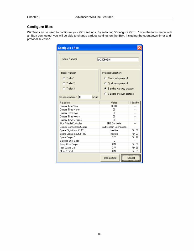
Chapter 9 Advanced WinTrac Features
85
Configure iBox
WinTrac can be used to configure your iBox settings. By selecting “Configure iBox…” from the tools menu with an iBox connected, you will be able to change various settings on the iBox, including the countdown timer and protocol selection.
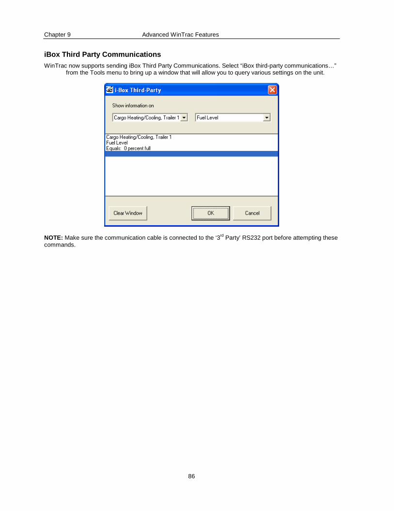
Chapter 9 Advanced WinTrac Features
86
iBox Third Party Communications
WinTrac now supports sending iBox Third Party Communications. Select “iBox third-party communications…” from the Tools menu to bring up a window that will allow you to query various settings on the unit.
NOTE: Make sure the communication cable is connected to the ‘3rd Party’ RS232 port before attempting these commands.
Chapter 10 Troubleshooting your WinTrac Software
87
Chapter 10
Troubleshooting your WinTrac Software
This section addresses some common WinTrac issues and provides the answers to frequently asked questions.
Logging WinTrac Activity
WinTrac communicates with many types of hardware, some of which may have newer versions under development. It may be possible to come across a rare problem which the manufacturers would like additional information on. This is not normally necessary for most problems. If you want WinTrac to log additional information on a problem:
1. Click on Help: Debugging options.
2. Click on Start Debug Logging.
A DOS prompt window should open up in the background. Leave it open and repeat the process in WinTrac that causes the problem. If needed, you can exit and restart WinTrac; the logging part continues independent of whether WinTrac is running or not. When finished, you can close the DOS prompt window, and a log file will have been created in your Program Files\Thermo King\WinTrac 5\Logs directory with a filename beginning with “wtdbmon-“ followed by the days date, and an identifying number. Email this file to your TK Dealer along with details of the problem.
Windows XP Service Pack 2 Database Issues
If WinTrac has problems accessing the WinTrac Database on Windows XP Service Pack 2 and declares it to be corrupt or invalid, then this may be resolved by the following:
1. Browse to the folder containing the database, right click and select “Properties”. In the properties dialog, there should be a "Security" tab that allows you to change file permissions.
2. In Windows XP SP2 this "Security" tab might be missing. If it is present, you can skip on to step 4.
3. Open the “My Computer” folder. Click on the menu option "Tools" and select "Folder Options". The tab "View" will have an option at the bottom that says "Use simple file sharing (Recommended)". Deselect that feature and click "Ok". The security tab should now be available.
4. In the security tab, grant the current user full access to the database file, directory and subdirectories.
Unspecified Database Error
You may receive this error if you have corrupted a database by moving data incorrectly between two databases. If you copy WinTrac Raw Download files (.wtd) files from one database to another, you may receive this error. To fix this, delete or move the .wtd files from your current databases ‘\Download’ directory.
Chapter 10 Troubleshooting your WinTrac Software
88
Installer Issues
"Setup has detected that uninstall shield is in use . Please close uninstall shield and restart setup. Error 432."
This error will occur on some Windows systems when you try to install if you do not have full administrative privileges. Log in to an account with administrative privileges before running the installer. You may need to contact your system administrator to alter administrative privileges.
Failure Code -106:
Installation media is corrupt. Your CD has been damaged, or is dirty. Try cleaning your CD and your CD drive.
Microsoft Office applications do not run after inst alling WinTrac:
This can happen if the Microsoft Office toolbar is left running during the installation. Re-installing WinTrac should fix this. Note: Re-installing Microsoft Office will not fix this problem.
Microsoft Office Installation Dialogs
On first using a feature of WinTrac, a dialog box may pop up trying to find Microsoft Office installation media. On certain PC setups, Microsoft office does not fully install features until they are used. This message is showing that windows is trying to access a portion of the Microsoft Office suite that is not fully installed. To resolve this problem, insert your Microsoft Office Installation disc into the PC and follow the instructions for installing the missing portions.
Microsoft Office will only install features at a later point from similar media, say: if you have Microsoft 2000 Premium, you need to use the Premium CD's, if you have Microsoft 2000 Pro, you need the Pro CD's. It will not allow you to install the missing features from a different release.
To work around this problem, either similar CDs to those originally used to install office must be used, or Microsoft Office could be uninstalled.
Printer Issues
Not enough memory when printing to Postscript Print er:
If your printer supports PCL, try printing as PCL (non-postscript), add more memory to printer, or try printing at a lower resolution (e.g. select 300dpi on a 600dpi printer).
Chapter 10 Troubleshooting your WinTrac Software
89
Communications Issues
Failed to communicate with TK units:
Failed to communicate with TK units - check power and connections. This means that WinTrac software was unable to establish a communications link with your TK unit. The most common reason for this is that you have selected the wrong COM port, or the cable connecting your TK unit to your PC is not connected properly.
Unable to open COM port:
This means that another software application is already using the COM port that you have selected. This is especially common on Portables, as COM port is usually taken by the Infra Red port or a pointing device, e.g. Mouse. Select an alternative COM port, or shut down the software using the COM port that you cannot access.
COM Port missing:
When using a USB / Serial connection in Windows XP, the COM port is dynamic and will often change, particularly after a laptop goes to sleep. To fix this, reboot your laptop. Then follow these steps to identify which COM port your USB adapter is using.
1. Click Start. Move your mouse over My Computer and right click.
2. Choose Manage from the menu.
3. Select Device Manager on the left. On the right, double click Ports (COM and LPT)
4. Look to see what COM port your adapter uses.
5. Open WinTrac. Choose Global settings from the View menu. Click the Communications tab and select the COM port that matches your USB adapter.
Disabling the Infra Red port on IBM Laptops:
Customers using IBM ThinkPad laptops should ensure that the Infra Red port is disabled. The Infra Red port is disabled using the ‘ThinkPad Features’ software application found in the ‘ThinkPad’ program folder.
Computer shutting down with a Blue Screen:
Customers using a USB / Serial connection with out of date drivers may experience this error. Downloading the latest drivers from the manufacturer’s website should resolve this problem.
Graphics Issues
Including a screenshot of WinTrac in a Word documen t
To capture the WinTrac screenshot, press <Alt> and <Print Screen> keys simultaneously. This will place a copy of the WinTrac window into your Windows Clipboard. In the Word application select Paste from the Edit menu. A copy of WinTrac screen will be pasted into your document. You can use this technique with other Windows applications, e.g. PowerPoint.
Chapter 10 Troubleshooting your WinTrac Software
90
Attaching WinTrac files to Notes and E-mails
To attach a WinTrac file to a Lotus Notes memo (or another e-mail application):
1. Note the full file name and path of the file that you wish to attach. The full name and path of a file is displayed in the right-hand pane of the File Management Window in WinTrac.
2. From Notes, choose the menu option Attach (or insert file from other e-mail apps)
3. Using the file name and path, locate the file to be attached. E.g. in Windows XP, if using the default database location, the directory will be C:\Documents and Settings\All Users\Application Data\Thermo King\WinTracDB\Files . Within WinTrac, you can select “Browse to Files” from the “File” menu to open a windows explorer window at that directory.
4. If you want to send a Raw Download file, you will find these files in the \Download directory under your WinTrac database. E.g. in Windows XP, if using the default database location, you will find the raw download files in C:\Documents and Settings\All Users\Application Dat a\Thermo King\WinTracDB\Download .
Chapter 11 License Agreement
91
Chapter 11
License Agreement
Thank you for purchasing Thermo King WinTrac Software. It is important that you read this notice before using this Software. If you choose not to be bound by the terms and conditions of this agreement, promptly return the complete package.
OWNERSHIP OF PROGRAM
This Software was developed for Thermo King Corporation and Thermo King holds an exclusive license for the transport temperature control industry, with the right to sublicense. Thermo King is willing to let you use this Software under the following terms and conditions listed below. Nothing contained herein shall be deemed to convey any title or ownership interest in the Software to you.
LICENSE
Thermo King Corporation grants you a non-exclusive, non-transferable license to use WinTrac Software under the following conditions:
You use the Software with a single-user system at your normal place of business.
You will not transfer, lease, or otherwise rent the Software to another party.
You will not merge, modify, or reverse-engineer the licensed Software.
You acknowledge that the Software includes proprietary information of Thermo King and the developer and you will utilize your best efforts to protect the Software and the information it contains.
BACK-UP COPY POLICY
You have the right to load the contents of the installation media into a computer and you may copy the Software solely for back-up or archival purposes.
LIMITATION OF LIABILITY
WinTrac software is made available to you on an “AS IS, WHERE IS” basis, without any warranty of any kind, expressed or implied.
Thermo King expressly disclaims ALL IMPLIED WARRANTIES OF MERCHANTABILITY AND FITNESS FOR A PARTICULAR PURPOSE, AND ALL WARRANTIES ARISING FROM COURSE OF DEALING, OR USAGE OF TRADE.
Thermo King shall have no responsibility of any kind for:
the correctness of the Software.
your ability to use the Software or consequences of using the Software.
problems arising from defects in the Software.
claims of third parties arising from use by you.
any special, indirect, incidental, or consequential damages whatsoever. Accordingly, you shall indemnify and hold Thermo King, its subcontractors, developers, or suppliers of any tier, harmless from any loss, liability or expense arising out of your use of the Software.
TERM
This license agreement is in effect as long as you use the Software in your normal business. Thermo King may terminate this agreement at any time if you are in breach of any term or condition set forth herein. You may terminate your obligation of confidentiality by discontinuing use of the Software, erasing the Software from your computer and returning the Software to Thermo King.

Chapter 11 License Agreement
92
Related Documents