Three Phase Inverter 1. Introduction: An inverter is an electronic device that changes direct supply voltage (DC) to alternating supply voltage (AC). Three phase inverters are generally used for high power applications. The three phase square wave invertor can be used to generate balanced three phase ac voltages with desired frequency. However harmonic voltages of 3 rd , 5 th and other non-triplet odd multiples of fundamental frequency distorts the output voltage. These distortions are very difficult to remove. We design different filters to remove these distortions but it is very tedious task. There are some other kinds of inverters such as pulse width modulated (PWM) inverters, which can provide a higher quality of output voltage. Circuit diagram of three phase invertor: 1.1 Simulations For 120 degree conduction

Welcome message from author
This document is posted to help you gain knowledge. Please leave a comment to let me know what you think about it! Share it to your friends and learn new things together.
Transcript

Three Phase Inverter
1. Introduction:
An inverter is an electronic device that changes direct supply voltage (DC) to
alternating supply voltage (AC).
Three phase inverters are generally used for high power applications. The three
phase square wave invertor can be used to generate balanced three phase ac
voltages with desired frequency. However harmonic voltages of 3rd, 5th and other
non-triplet odd multiples of fundamental frequency distorts the output voltage. These
distortions are very difficult to remove. We design different filters to remove these
distortions but it is very tedious task. There are some other kinds of inverters such
as pulse width modulated (PWM) inverters, which can provide a higher quality of
output voltage.
Circuit diagram of three phase invertor:
1.1 Simulations For 120 degree conduction
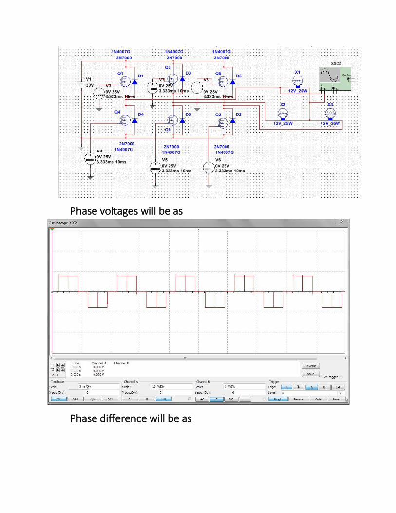
Phase voltages will be as
Phase difference will be as

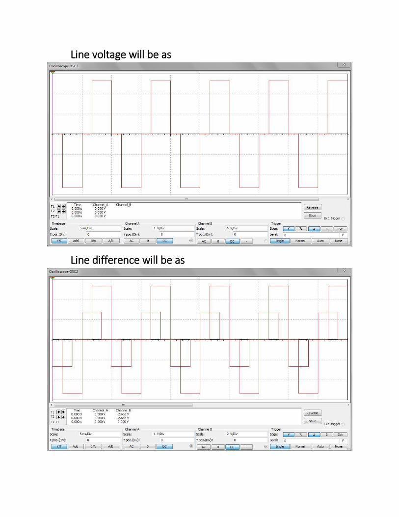
Line voltage will be as

Line voltage difference will be as
For 180 degree Conduction
Line voltage will be as
Line difference will be as
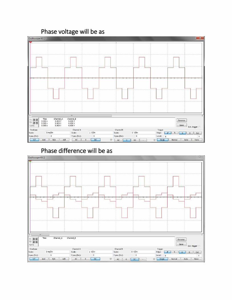
Phase voltage will be as
Phase difference will be as

2. Modes of conduction:
There are two modes of conduction:
i. 180 degrees’ conduction
ii. 120 degrees’ conduction
2.1 180o conduction:
In this mode of operation each switch conducts for half cycle. At any instant of
time three switches are ON. When S1 is ON, the terminal A gets connected to the
positive terminal of input DC source, at the same time its complementary switch
S4 remains off. Similarly, when S4 is ON, terminal A gets connected with the
negative terminal of the DC source. These combinations are same for S3, S6
(terminal B) and S5, S2 (terminal C). There are six possible modes of operation in
a cycle and each is of 60 degree.
Equivalent circuit
For Y-connected resistive load for step1 (0-60 degree), others are similar to this:

For step 1 (0-60 degree) S1, S6, S5 will conduct A and B will be connected with
positive terminal of DC source and C will be connected with negative terminal of
DC source. Equivalent resistance is equal to
𝑅𝑒𝑞 = 𝑅 +𝑅 ∗ 𝑅
𝑅 + 𝑅
𝑅 +𝑅
2=
3𝑅
2
Current can be calculated as
𝑖 =𝑉𝑔
𝑅𝑒𝑞
=2𝑉𝑔
3𝑅
Phase Voltages can be calculated as
𝑉𝑎𝑛 = 𝑉𝑐𝑛 =𝑅
23𝑅
2
∗ 𝑉𝑔 = 1
3𝑉𝑔
𝑉𝑏𝑛 =𝑅
3𝑅
2
∗ 𝑉𝑔 = −2
3𝑉𝑔
Line to line voltages can be calculated as
𝑉𝑎𝑏 = 𝑉𝑎𝑛 − 𝑉𝑏𝑛 = 𝑉𝑔
𝑉𝑏𝑐 = 𝑉𝑏𝑛 − 𝑉𝑐𝑛 = −𝑉𝑔
𝑉𝑐𝑎 = 𝑉𝑐𝑛 − 𝑉𝑎𝑛 = 0

We can calculate voltages for other steps by following same procedure.
2.1.1 Waveforms
There waveforms are shown of phase voltages and line to line voltages are
shown:
For line to line voltages between A & B
For Phase voltages
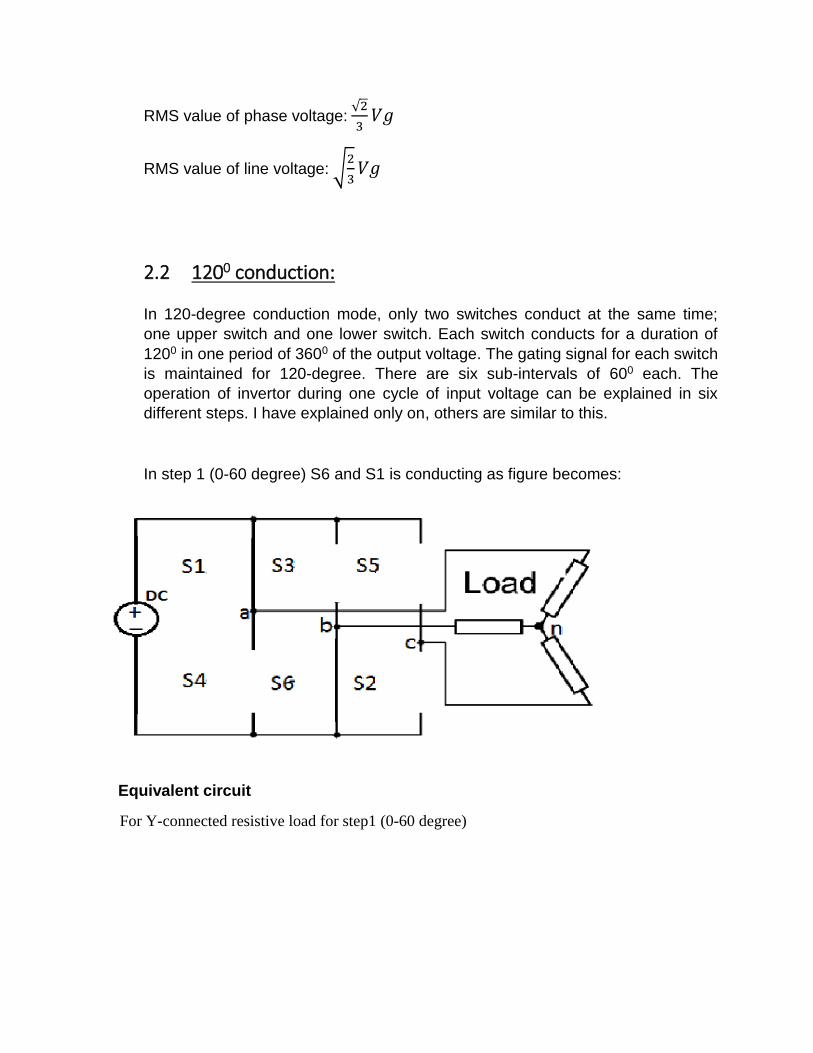
RMS value of phase voltage: √2
3𝑉𝑔
RMS value of line voltage: √2
3𝑉𝑔
2.2 1200 conduction:
In 120-degree conduction mode, only two switches conduct at the same time;
one upper switch and one lower switch. Each switch conducts for a duration of
1200 in one period of 3600 of the output voltage. The gating signal for each switch
is maintained for 120-degree. There are six sub-intervals of 600 each. The
operation of invertor during one cycle of input voltage can be explained in six
different steps. I have explained only on, others are similar to this.
In step 1 (0-60 degree) S6 and S1 is conducting as figure becomes:
Equivalent circuit
For Y-connected resistive load for step1 (0-60 degree)
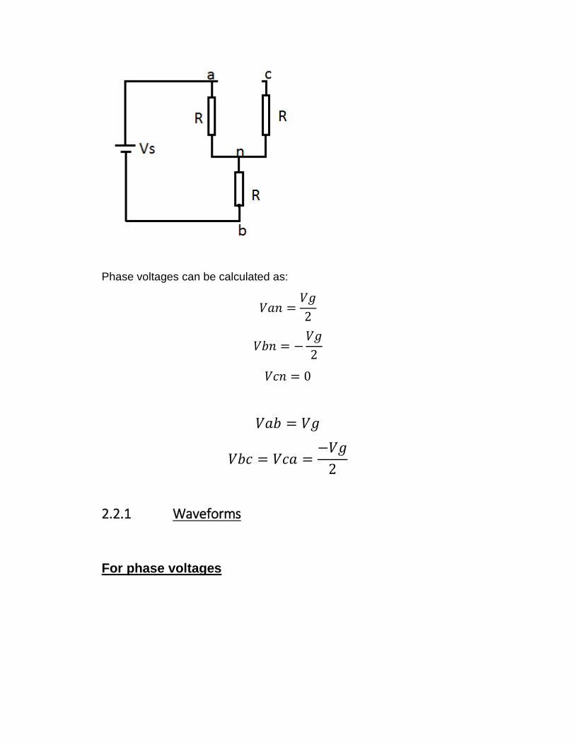
Phase voltages can be calculated as:
𝑉𝑎𝑛 =𝑉𝑔
2
𝑉𝑏𝑛 = −𝑉𝑔
2
𝑉𝑐𝑛 = 0
𝑉𝑎𝑏 = 𝑉𝑔
𝑉𝑏𝑐 = 𝑉𝑐𝑎 =−𝑉𝑔
2
2.2.1 Waveforms
For phase voltages
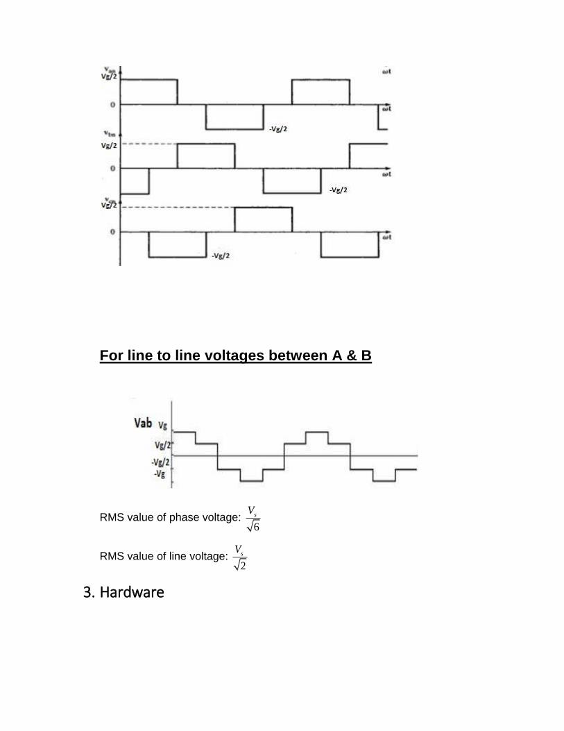
For line to line voltages between A & B
RMS value of phase voltage: 6
sV
RMS value of line voltage: 2
sV
3. Hardware

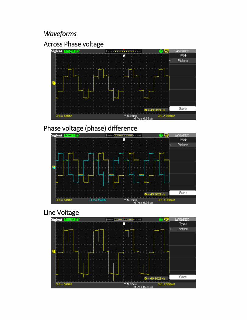
Waveforms
Across Phase voltage
Phase voltage (phase) difference
Line Voltage

Line voltage Phase difference
After Passing through Filter
Related Documents