Cumhuriyet Üniversitesi Fen Fakültesi Fen Bilimleri Dergisi (CFD), Cilt:36, No: 3 Özel Sayı (2015) ISSN: 1300-1949 Cumhuriyet University Faculty of Science Science Journal (CSJ), Vol. 36, No: 3 Special Issue (2015) ISSN: 1300-1949 _____________ *Corresponding author. Email address: [email protected] Special Issue: The Second National Conference on Applied Research in Science and Technology http://dergi.cumhuriyet.edu.tr/cumuscij ©2015 Faculty of Science, Cumhuriyet University Open-Delta Three-Phase Inverter Current Control Using Predictive Control For PV System Connected To The Grid Zohre ABBASİ 1 , Hassan FESHKİ FARAHANİ 2 1 MSc - Department of Electrical Engineering, Islamic Azad University, Ashtian Branch, Ashtian, Iran 2 Assistant Professor- Department of Electrical Engineering, Islamic Azad University, Ashtian Branch, Ashtian, Iran Received: 01.02.2015; Accepted: 05.05.2015 Abstract. Predictive control method has advantages such as simple structure, functional and follow the simple mathematical. In this paper, a new method is provided for controlling the open-Delta three-phase inverter . Model- based predictive control system is used for controlling the current of a open-Delta three-phase inverter, which is in the process of converting the photovoltaic energy conversion plays a three-phase network. The controller at any time, the next period current are estimated using a model system. Four switches are used to build a open-delta three-phase inverter, that Four signal switches are necessary for inverter and Signals can be done based on the cost function minimization. Open-Delta Three-phase inverter, produces four pulses required to conduct two basic switching using switching PWM. Appropriate choice of switching states and estimated future states of the phase currents, the inverter may be provided with reasonable accuracy the phase currents. In this study the effect of different parameters such as: inductance coupling inductors, capacitors and reference current is evaluated on the performance of the proposed controller. A sample of inverters, with nominal power 3300 VA is simulated by SIMULINK MATLAB software. At the simulation section of paper, An example of the current predictive controller is designed for Open-Delta three- phase inverter , and is implemented in SIMULINK MATLAB software. The current predictive controller for the six- switch three-phase inverter is designed and implemented in SIMULINK MATLAB software and simulation results have been compared both three-phase inverter topology. Keywords: PV systems, Open-Delta three phase inverters, Estimated load, Model-based predictive control method 1. INTRODUCTİON In recent years, due to the limitations of renewable energies and environmental pollution, human attention has been directed towards the use of renewable energies. Solar energy as a clean and renewable energy source that has attracted a lot of attention to. Pv system, solar energy is directly converted to electrical energy. With growing semiconductor industry in recent years and reduce production costs semiconductor devices, today's solar arrays have found wide applications in the grid-connected Pv systems can be pointed out. Pv system have various fields. Depending on the type of user to delete some parts there. Pv system in perfect condition, including solar cell, regulatory point of maximum power, voltage regulators, controlling the rate of charge and discharge the battery, energy storage unit and the inverter voltage. The proposed components according to the requirements and needs of consumers and to reduce costs can be reduced, thus the use of the inverter voltage or voltage storage unit for all Pv system generate electricity does not use [1].

Welcome message from author
This document is posted to help you gain knowledge. Please leave a comment to let me know what you think about it! Share it to your friends and learn new things together.
Transcript
Cumhuriyet Üniversitesi Fen Fakültesi Fen Bilimleri Dergisi (CFD), Cilt:36, No: 3 Özel Sayı (2015)
ISSN: 1300-1949
Cumhuriyet University Faculty of Science Science Journal (CSJ), Vol. 36, No: 3 Special Issue (2015)
ISSN: 1300-1949
_____________
*Corresponding author. Email address: [email protected]
Special Issue: The Second National Conference on Applied Research in Science and Technology
http://dergi.cumhuriyet.edu.tr/cumuscij ©2015 Faculty of Science, Cumhuriyet University
Open-Delta Three-Phase Inverter Current Control Using Predictive Control For PV System Connected To The Grid
Zohre ABBASİ 1, Hassan FESHKİ FARAHANİ 2
1MSc - Department of Electrical Engineering, Islamic Azad University, Ashtian Branch, Ashtian, Iran
2Assistant Professor- Department of Electrical Engineering, Islamic Azad University, Ashtian Branch, Ashtian, Iran
Received: 01.02.2015; Accepted: 05.05.2015
Abstract. Predictive control method has advantages such as simple structure, functional and follow the simple mathematical. In this paper, a new method is provided for controlling the open-Delta three-phase inverter . Model-based predictive control system is used for controlling the current of a open-Delta three-phase inverter, which is in the process of converting the photovoltaic energy conversion plays a three-phase network. The controller at any time, the next period current are estimated using a model system. Four switches are used to build a open-delta three-phase inverter, that Four signal switches are necessary for inverter and Signals can be done based on the cost function minimization. Open-Delta Three-phase inverter, produces four pulses required to conduct two basic switching using switching PWM. Appropriate choice of switching states and estimated future states of the phase currents, the inverter may be provided with reasonable accuracy the phase currents. In this study the effect of different parameters such as: inductance coupling inductors, capacitors and reference current is evaluated on the performance of the proposed controller. A sample of inverters, with nominal power 3300 VA is simulated by SIMULINK MATLAB software. At the simulation section of paper, An example of the current predictive controller is designed for Open-Delta three-phase inverter , and is implemented in SIMULINK MATLAB software. The current predictive controller for the six-switch three-phase inverter is designed and implemented in SIMULINK MATLAB software and simulation results have been compared both three-phase inverter topology. Keywords: PV systems, Open-Delta three phase inverters, Estimated load, Model-based predictive control method 1. INTRODUCTİON
In recent years, due to the limitations of renewable energies and environmental pollution,
human attention has been directed towards the use of renewable energies. Solar energy as a
clean and renewable energy source that has attracted a lot of attention to. Pv system, solar
energy is directly converted to electrical energy. With growing semiconductor industry in recent
years and reduce production costs semiconductor devices, today's solar arrays have found wide
applications in the grid-connected Pv systems can be pointed out. Pv system have various fields.
Depending on the type of user to delete some parts there. Pv system in perfect condition,
including solar cell, regulatory point of maximum power, voltage regulators, controlling the rate
of charge and discharge the battery, energy storage unit and the inverter voltage. The proposed
components according to the requirements and needs of consumers and to reduce costs can be
reduced, thus the use of the inverter voltage or voltage storage unit for all Pv system generate
electricity does not use [1].
ABBASİ, FESHKİ FARAHANİ
122
One of the most important parts of solar cells for energy exchange with the grid converters is
DC / AC inverter. Open-Delta are the type of connection used in this article. Characteristics of
converters, high efficiency and power factor inputs can be cited. Considering the loads fed by
the converter must have high reliability. Reduce the number of switches used in disguised as
one of the most expensive components used in the converter structure has been considered.
Articles and studies on the use of this topology is reported [2-9].
The control method is one of the most important issues in the use of inverters, The different
control methods in this context is provided, Such as Multi-loop feedback control method [1, 10-
11], the controller is Deadbeat [12-14], adaptive controller based on resonant filter banks [15-
16], controller-based replication [17-18]. Predictive control method is one of the other control
methods, different algorithms have been proposed as predictive control. Current control can be
used in various applications such as active power filters [19-20], Preset power factor [21],
inverters [19, 22], rectifiers [22] and non-interrupted power supply [14, 23]. In recent years,
various studies have been done to improve the control method [24-27].
In this paper, the open-delta three-phase inverter with nominal power 3300VA is designed by
the predictive controller. And simulation in the SIMULINK MATLAB.
2. STRUCTURE of the OPEN-DELTA THREE-PHASE İNVERTER
In conventional inverters can reduce the number of switches from six to four inverters can be
found Open-Delta three phase inverter. In this type of inverter replacement capacitor instead of
two switches located on the base and reduced number of switches.
IaIb
Ic
S21
S22
S31
S32
+
-
S11
S12
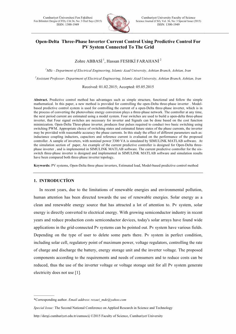
Figure 1. The six-switch three-phase inverter voltage source.
Open-Delta Three-Phase Inverter Current Control Using Predictive Control For PV System
Connected To The Grid
123
IaIb
Ic
S21
S22
S31
S32
+
-
C1
C2
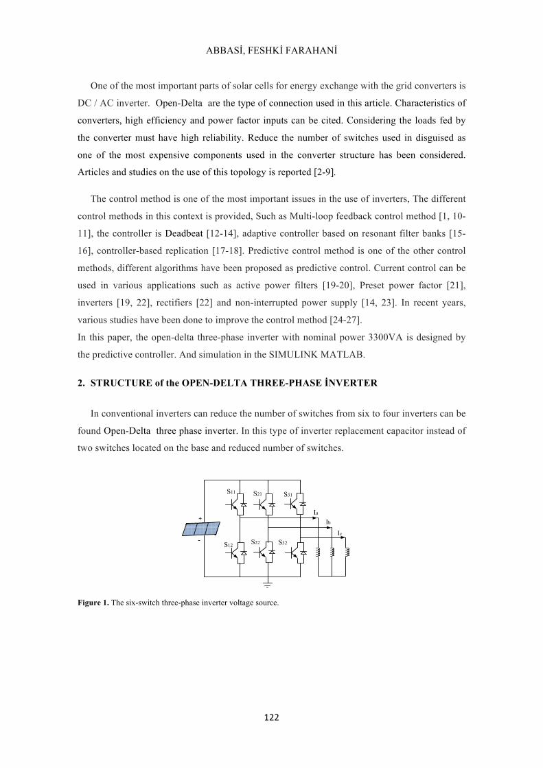
Figure 2. Open-Delta three phase inverter voltage source.
Six switch inverters are the most common form of three phase inverters, the topology of the
converter in Figure 1 is shown. In this inverter, the six-switch inverter is used as a bridge
inverter. In this figure if the capacitor is used instead of swithes (S11 and S12), there will be
open delta three-phase inverter that In Figure (2) is shown. Open-Delta three-phase inverter,
compared to six switch three-phase inverter has advantages such as: Reduce the number of
facilities including a reduction in the number of semiconductor (switches and diodes), Reduce
the cost of inverters, Reduced switching losses, Reduce the complexity of the control circuit,
Increased reliability and Reduce the space occupied Converter. The only limit to four switch
inverter, is DC link capacitor voltage unbalance, which this problem can be reduced by
appropriate control. Various methods have been proposed for balance voltage that can be
minimized ripple voltage by using different performs.
3. MODEL-BASED PREDİCTİVE CONTROL
Today, the control of industrial processes and the selection of a suitable method for this
purpose is very important. Control algorithm used in industry should be desired capabilities,
including its ease of use by the operator and simple setting , In fact, it will be your baseline for
the development of industrial applications. Although the PID controller is common in the
industry, but industrial processes involving the dynamic range of different behaviors that are
limiting the use of such a controller. Thus, the predictive control method is a method of control
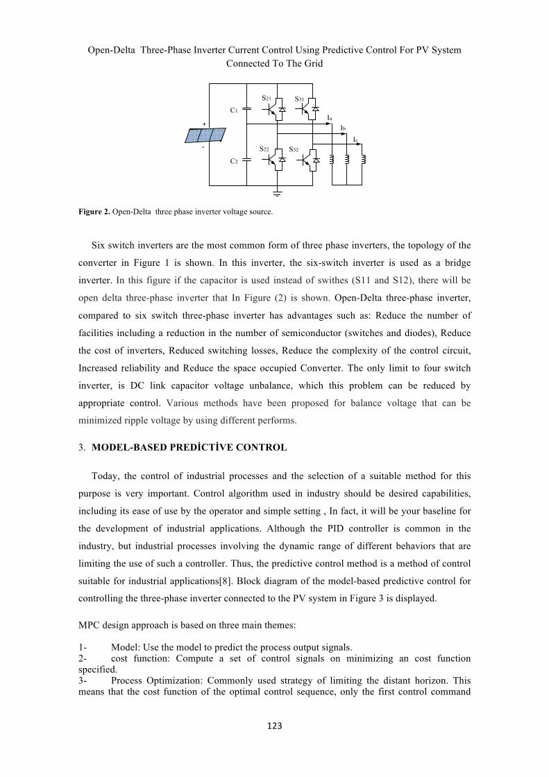
suitable for industrial applications[8]. Block diagram of the model-based predictive control for
controlling the three-phase inverter connected to the PV system in Figure 3 is displayed.
MPC design approach is based on three main themes:
1- Model: Use the model to predict the process output signals. 2- cost function: Compute a set of control signals on minimizing an cost function specified. 3- Process Optimization: Commonly used strategy of limiting the distant horizon. This means that the cost function of the optimal control sequence, only the first control command
ABBASİ, FESHKİ FARAHANİ
124
string to apply the process and the next steps to optimize the operation of repeated again.
VDCIa(i)
3phase inverter
Ib(i)
Ic(i)
grid
SaSbSc
Process Optimization
Cost function
Ia(i+1)Ib(i+1)Ic(i+1)
Ia*Ib*
Load model
+-
Ic*
inputMPC
output MPC
+-+-
Figure 3. Diagram of a grid-connected Pv system by using predictive control
3.1. Inverter system model
Three-phase inverter has the currents and sinusoidal voltages with a phase difference of 120
degrees from each other. Inverter output current and voltage space vector is shown as follows:
(1)
(2)
is different phase‚Three-phase voltage vector.
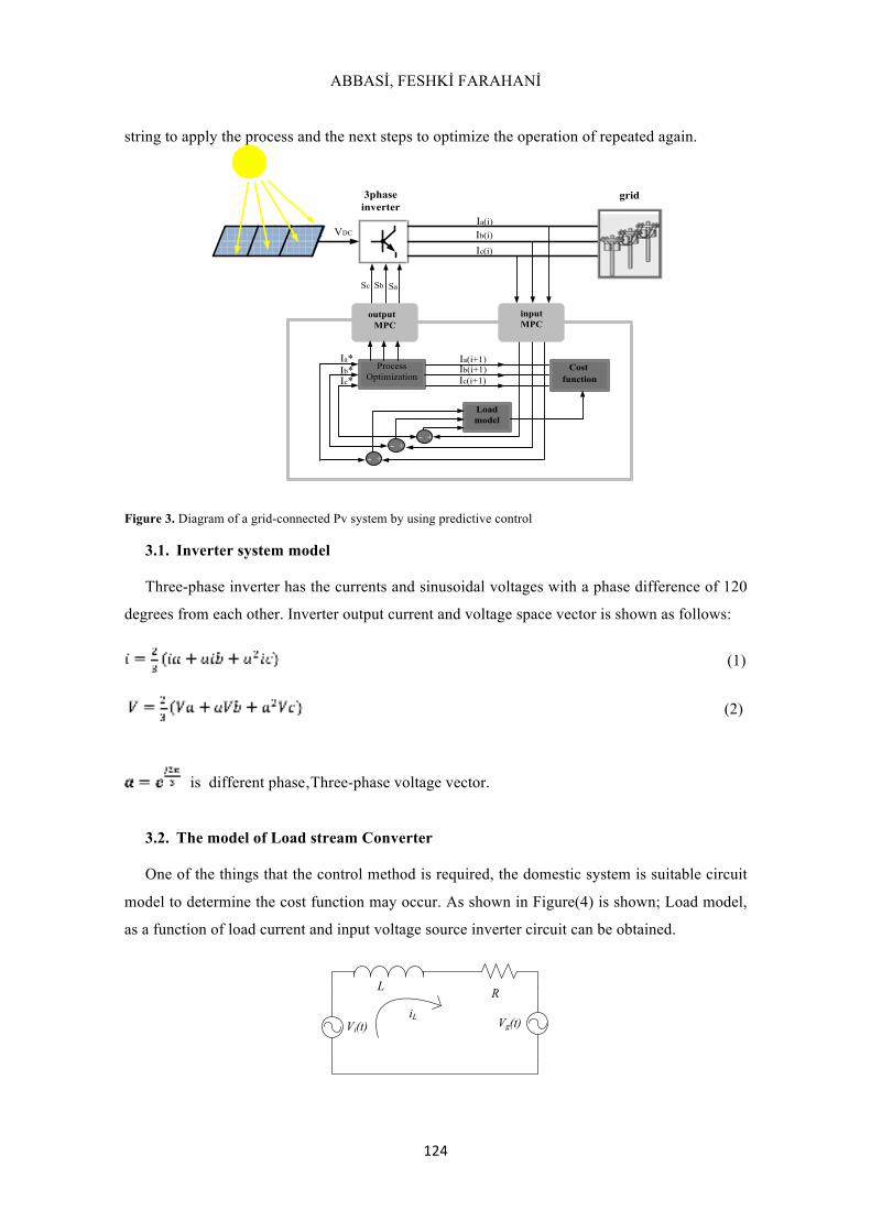
3.2. The model of Load stream Converter
One of the things that the control method is required, the domestic system is suitable circuit
model to determine the cost function may occur. As shown in Figure(4) is shown; Load model,
as a function of load current and input voltage source inverter circuit can be obtained.
L RiL
Vi(t) Vg(t)

Open-Delta Three-Phase Inverter Current Control Using Predictive Control For PV System
Connected To The Grid
125
Figure 4. Inverter Load Model.
Using the inverter load model can easily flow into the Load model to determine the cost
function is achieved. Dynamic load Converter can be defined as follows:
(3)
Which can be related (3) to form discrete wrote as follows:
(4)
Ts :during the sampling period k :k-th sample is selected
]1[ +ki pL : To estimate current future state, with k + 1
][kiL : k-th sample is output current inverter
][],[ kVkV ig : k-th sample is grid voltage and output voltage inverter
3.3. Predicting the cost function
The cost function is one of the most important parts of the predictive control. The switching
signals for the next interval is determined based on the cost function, This function is defined as
follows:
LL iig −= *
(5) *Li is Current reference values.Using the previous section, we can obtain the three-phase
inverter costs. In the case where k = k + 1 we have: [ ] [ ] [ ] [ ]( )1112 +−+×++×=+ kVkVBkiAki giLPL (6) That:
LTRA s×
−=1 (7)
LTB s= (8)
Assuming a forecast horizon of one step, Usually, the future values of the load current and
the evaluation of the cost function for each voltage vector that can be used in a period And in
order to be selected. Voltage vector that minimizes the cost function is to select the next
sampling period. The red part of Figure 5 represents the output signals MPC is applied, which
provides commands for controlling the phase inverter. As in part (a) of Figure (5) is used to
control the six-switch three-phase inverter, three phase control signal is needed and the MPC
ABBASİ, FESHKİ FARAHANİ
126
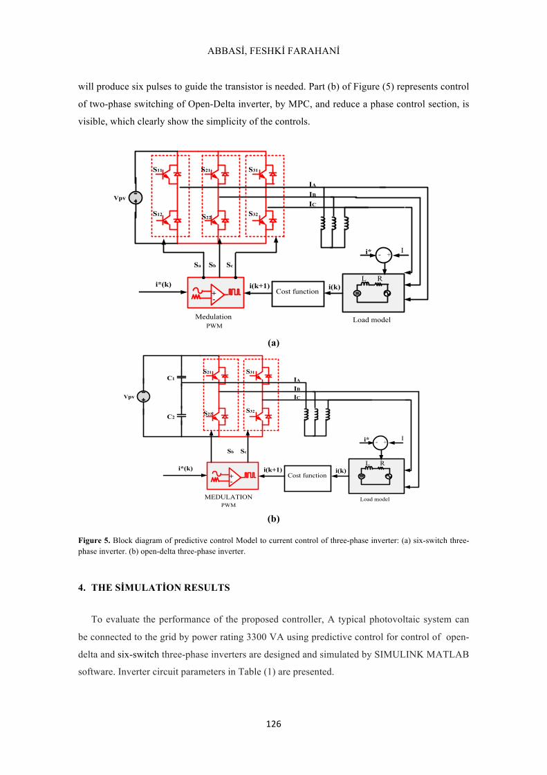
will produce six pulses to guide the transistor is needed. Part (b) of Figure (5) represents control
of two-phase switching of Open-Delta inverter, by MPC, and reduce a phase control section, is
visible, which clearly show the simplicity of the controls.
IAIBIC
i(k+1)i*(k) i(k)
S11
S12
S21
S22
S31
S32
Sa Sb Sc
+-
RL
+-
Cost function
Load model Medulation PWM
Ii*
Vpv
(a)
IAIBIC
i(k+1)i*(k) i(k)
S21
S22
S31
S32
Sb Sc
+-
RL
+-
Cost function
Load model MEDULATION PWM
Ii*
Vpv
C1
C2
(b)
Figure 5. Block diagram of predictive control Model to current control of three-phase inverter: (a) six-switch three-phase inverter. (b) open-delta three-phase inverter.
4. THE SİMULATİON RESULTS
To evaluate the performance of the proposed controller, A typical photovoltaic system can
be connected to the grid by power rating 3300 VA using predictive control for control of open-
delta and six-switch three-phase inverters are designed and simulated by SIMULINK MATLAB
software. Inverter circuit parameters in Table (1) are presented.
Open-Delta Three-Phase Inverter Current Control Using Predictive Control For PV System
Connected To The Grid
127
(9)
(10)
(11)
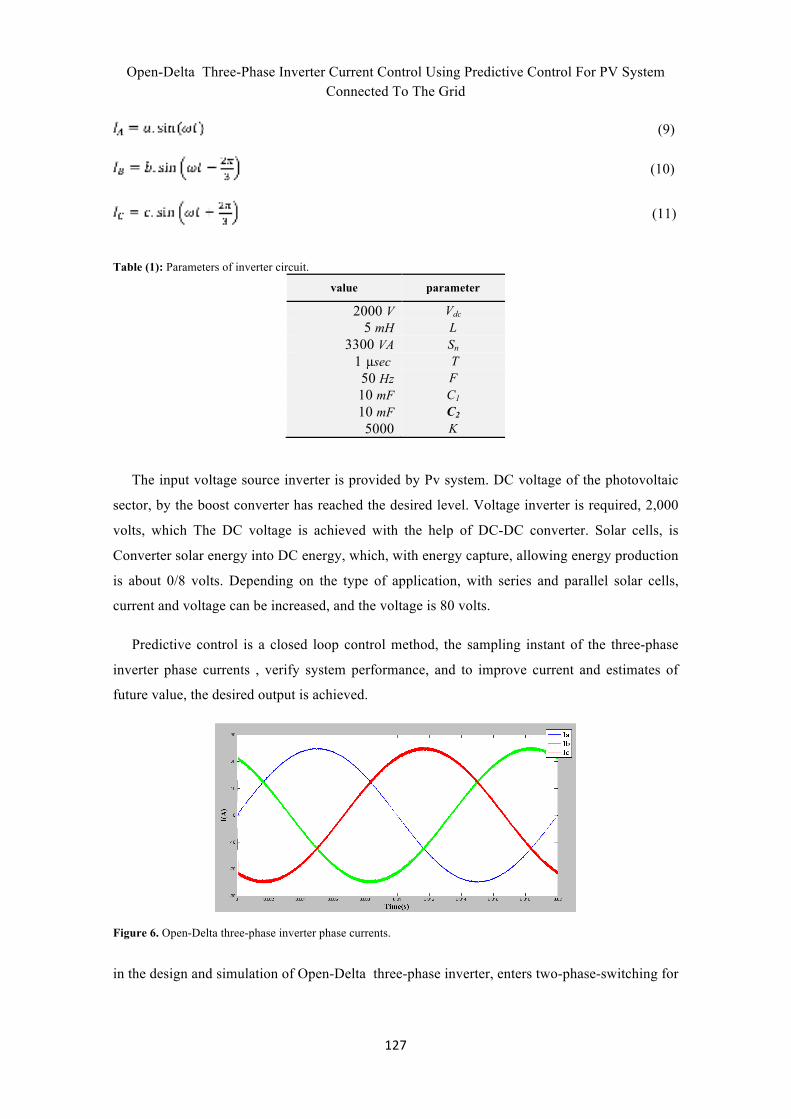
Table (1): Parameters of inverter circuit.
parameter value Vdc V 2000 L mH 5 Sn VA 3300 T secµ 1 F Hz 50 C1 mF 10 C2 mF 10 K 5000
The input voltage source inverter is provided by Pv system. DC voltage of the photovoltaic
sector, by the boost converter has reached the desired level. Voltage inverter is required, 2,000
volts, which The DC voltage is achieved with the help of DC-DC converter. Solar cells, is
Converter solar energy into DC energy, which, with energy capture, allowing energy production
is about 0/8 volts. Depending on the type of application, with series and parallel solar cells,
current and voltage can be increased, and the voltage is 80 volts.
Predictive control is a closed loop control method, the sampling instant of the three-phase
inverter phase currents , verify system performance, and to improve current and estimates of
future value, the desired output is achieved.
Figure 6. Open-Delta three-phase inverter phase currents.
in the design and simulation of Open-Delta three-phase inverter, enters two-phase-switching for
ABBASİ, FESHKİ FARAHANİ
128
the control. In Figure (6) and currents in Open-Delta inverter shown. Optional values are
compared with the reference waveform, that waveforms are sinusoidal, Differences between the
two waveforms is optimized, and as the output value will be applied to the inverter.
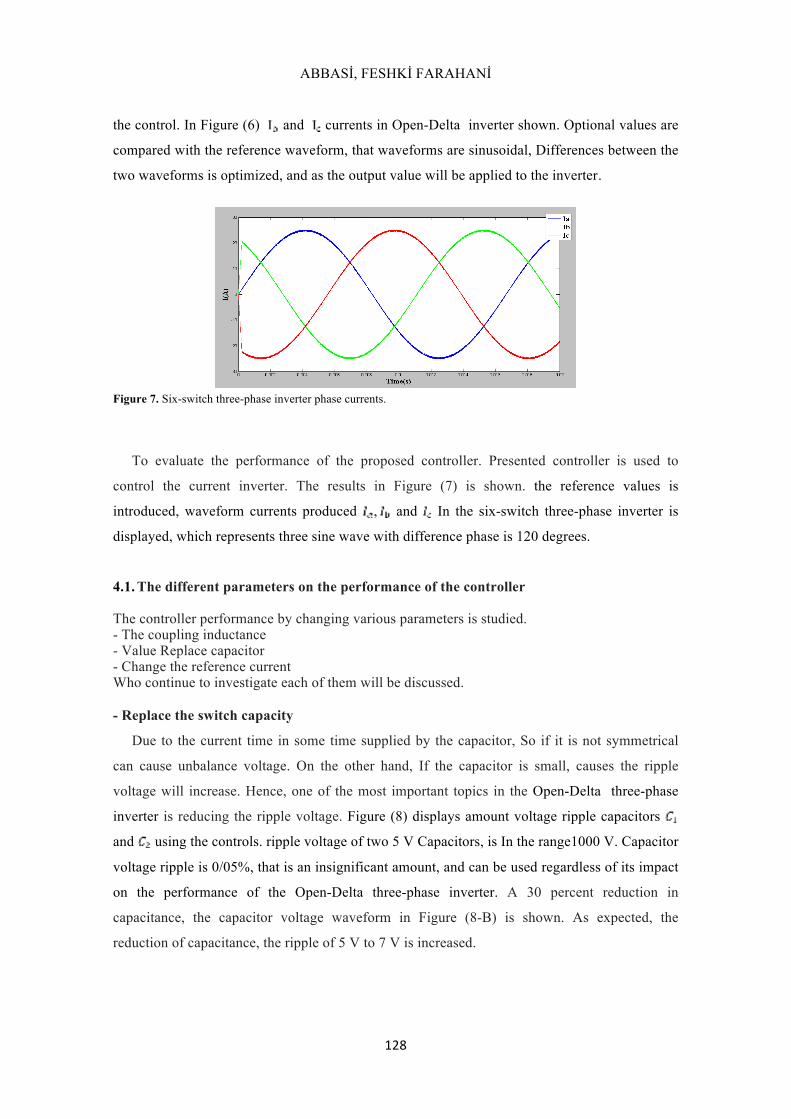
Figure 7. Six-switch three-phase inverter phase currents.
To evaluate the performance of the proposed controller. Presented controller is used to
control the current inverter. The results in Figure (7) is shown. the reference values is
introduced, waveform currents produced , and In the six-switch three-phase inverter is
displayed, which represents three sine wave with difference phase is 120 degrees.
4.1. The different parameters on the performance of the controller
The controller performance by changing various parameters is studied. - The coupling inductance - Value Replace capacitor - Change the reference current Who continue to investigate each of them will be discussed. - Replace the switch capacity
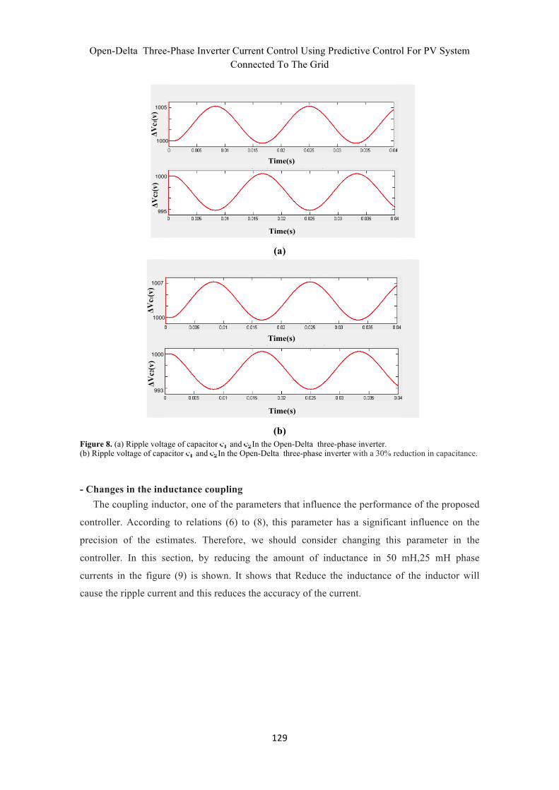
Due to the current time in some time supplied by the capacitor, So if it is not symmetrical
can cause unbalance voltage. On the other hand, If the capacitor is small, causes the ripple
voltage will increase. Hence, one of the most important topics in the Open-Delta three-phase
inverter is reducing the ripple voltage. Figure (8) displays amount voltage ripple capacitors
and using the controls. ripple voltage of two 5 V Capacitors, is In the range1000 V. Capacitor
voltage ripple is 0/05%, that is an insignificant amount, and can be used regardless of its impact
on the performance of the Open-Delta three-phase inverter. A 30 percent reduction in
capacitance, the capacitor voltage waveform in Figure (8-B) is shown. As expected, the
reduction of capacitance, the ripple of 5 V to 7 V is increased.
Open-Delta Three-Phase Inverter Current Control Using Predictive Control For PV System
Connected To The Grid
129
Time(s)ΔVc1(v)
1000
1005
ΔVc2(v)
Time(s)
1000
995
(a)
Time(s)
ΔVc1(v)
1000
1007
ΔVc2(v)
Time(s)
1000
993
(b)
Figure 8. (a) Ripple voltage of capacitor and In the Open-Delta three-phase inverter. (b) Ripple voltage of capacitor and In the Open-Delta three-phase inverter with a 30% reduction in capacitance. - Changes in the inductance coupling
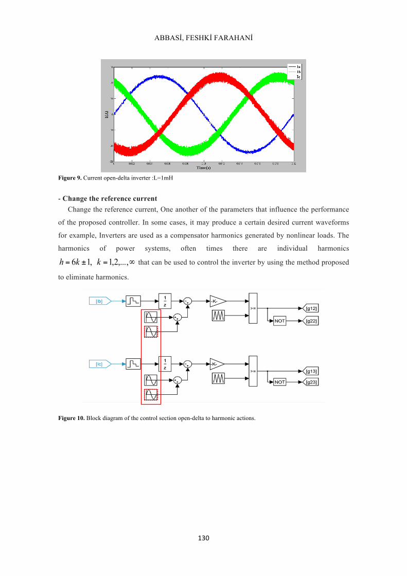
The coupling inductor, one of the parameters that influence the performance of the proposed
controller. According to relations (6) to (8), this parameter has a significant influence on the
precision of the estimates. Therefore, we should consider changing this parameter in the
controller. In this section, by reducing the amount of inductance in 50 mH,25 mH phase
currents in the figure (9) is shown. It shows that Reduce the inductance of the inductor will
cause the ripple current and this reduces the accuracy of the current.
ABBASİ, FESHKİ FARAHANİ
130
Figure 9. Current open-delta inverter :L=1mH
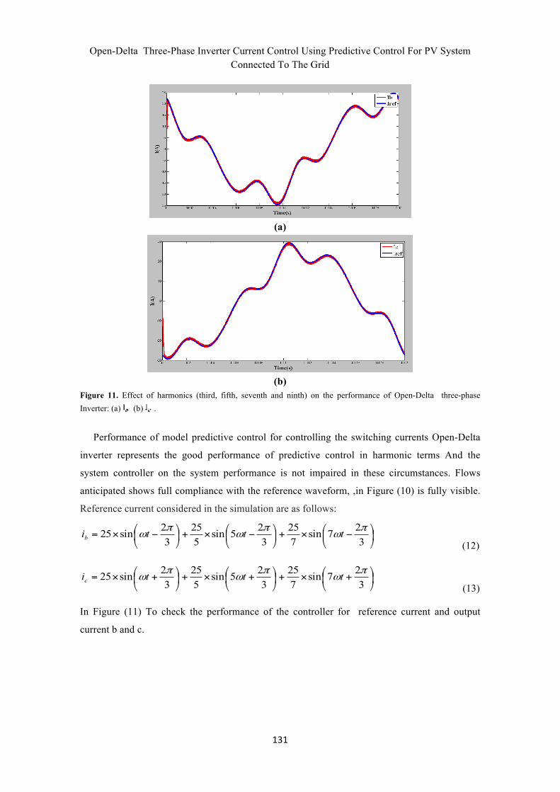
- Change the reference current
Change the reference current, One another of the parameters that influence the performance
of the proposed controller. In some cases, it may produce a certain desired current waveforms
for example, Inverters are used as a compensator harmonics generated by nonlinear loads. The
harmonics of power systems, often times there are individual harmonics
∞=±= ,...,2,1,16 kkh that can be used to control the inverter by using the method proposed
to eliminate harmonics.
Figure 10. Block diagram of the control section open-delta to harmonic actions.
Open-Delta Three-Phase Inverter Current Control Using Predictive Control For PV System
Connected To The Grid
131
(a)
(b)
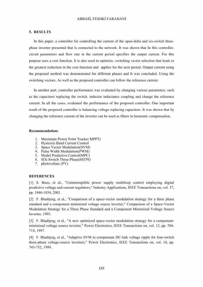
Figure 11. Effect of harmonics (third, fifth, seventh and ninth) on the performance of Open-Delta three-phase Inverter: (a) (b) .
Performance of model predictive control for controlling the switching currents Open-Delta
inverter represents the good performance of predictive control in harmonic terms And the
system controller on the system performance is not impaired in these circumstances. Flows
anticipated shows full compliance with the reference waveform, ,in Figure (10) is fully visible.
Reference current considered in the simulation are as follows:
⎟⎠
⎞⎜⎝
⎛ −×+⎟⎠
⎞⎜⎝
⎛ −×+⎟⎠
⎞⎜⎝
⎛ −×=327sin
725
325sin
525
32sin25 π
ωπ
ωπ
ω tttib (12)
⎟⎠
⎞⎜⎝
⎛ +×+⎟⎠
⎞⎜⎝
⎛ +×+⎟⎠
⎞⎜⎝
⎛ +×=327sin
725
325sin
525
32sin25 π
ωπ
ωπ
ω tttic (13)
In Figure (11) To check the performance of the controller for reference current and output
current b and c.
ABBASİ, FESHKİ FARAHANİ
132
5. RESULTS
In this paper, a controller for controlling the current of the open-delta and six-switch three-
phase inverter presented that is connected to the network. It was shown that In this controller,
circuit parameters and flow rate in the current period specifies the output current. For this
purpose uses a cost function. It is also used to optimize, switching vector selection that leads to
the greatest reduction in the cost function and applies for the next period. Output current using
the proposed method was demonstrated for different phases and It was concluded. Using the
switching vectors, As well as the proposed controller can follow the reference current.
In another part, controller performance was evaluated by changing various parameters, such
as the capacitors replacing the switch, inductor inductance coupling and change the reference
current. In all the cases, evaluated the performance of the proposed controller. One important
result of the proposed controller is balancing voltage replacing capacitors. It was shown that by
changing the reference current of the inverter can be used as filters in harmonic compensation.
Recommendation:
1. Maximum Power Point Tracke (MPPT) 2. Hystersis Band Current Control 3. Space Vector Modulation(SVM) 4. Pulse Width Modulation(PWM) 5. Model Predictive Control(MPC) 6. SIX-Switch Three-Phase(6STPI) 7. photovoltaic (PV)
REFERENCES
[1] S. Buso, et al., "Uninterruptible power supply multiloop control employing digital predictive voltage and current regulators," Industry Applications, IEEE Transactions on, vol. 37, pp. 1846-1854, 2001.
[2] F. Blaabjerg, et al., "Comparison of a space-vector modulation strategy for a three phase standard and a component minimized voltage source inverter," Comparison of a Space-Vector Modulation Strategy for a Three Phase Standard and a Component Minimized Voltage Source Inverter, 1995.
[3] F. Blaabjerg, et al., "A new optimized space-vector modulation strategy for a component-minimized voltage source inverter," Power Electronics, IEEE Transactions on, vol. 12, pp. 704-714, 1997.
[4] F. Blaabjerg, et al., "Adaptive SVM to compensate DC-link voltage ripple for four-switch three-phase voltage-source inverters," Power Electronics, IEEE Transactions on, vol. 14, pp. 743-752, 1999.
Open-Delta Three-Phase Inverter Current Control Using Predictive Control For PV System
Connected To The Grid
133
[5] G.-T. Kim and T. A. Lipo, "VSI-PWM rectifier/inverter system with a reduced switch count," in Industry Applications Conference, 1995. Thirtieth IAS Annual Meeting, IAS'95., Conference Record of the 1995 IEEE, 1995, pp. 2327-2332.
[6] D. T. Liang and J. Li, "Flux vector modulation strategy for a four-switch three-phase inverter for motor drive applications," in Power Electronics Specialists Conference, 1997. PESC'97 Record., 28th Annual IEEE, 1997, pp. 612-617.
[7] W. McMurray, "Modulation of the chopping frequency in DC choppers and PWM inverters having current-hysteresis controllers," Industry Applications, IEEE Transactions on, pp. 763-768, 1984.
[8] R. Ribeiro, et al., "AC/AC converter with four switch three phase structures," in Power Electronics Specialists Conference, 1996. PESC'96 Record., 27th Annual IEEE, 1996, pp. 134-139.
[9] H. W. Van Der Broeck and J. D. Van Wyk, "A comparative investigation of a three-phase induction machine drive with a component minimized voltage-fed inverter under different control options," Industry Applications, IEEE Transactions on, pp. 309-320, 1984.
[10] P. C. Loh and D. G. Holmes, "Analysis of multiloop control strategies for LC/CL/LCL-filtered voltage-source and current-source inverters," Industry Applications, IEEE Transactions on, vol. 41, pp. 644-654, 2005.
[11] P. C. Loh, et al., "A comparative analysis of multiloop voltage regulation strategies for single and three-phase UPS systems," Power Electronics, IEEE Transactions on, vol. 18, pp. 1176-1185, 2003.
[12] M. Kojima, et al., "Novel vector control system using deadbeat-controlled PWM inverter with output LC filter," Industry Applications, IEEE Transactions on, vol. 40, pp. 162-169, 2004.
[13] O. Kukrer, "Deadbeat control of a three-phase inverter with an output LC filter," Power Electronics, IEEE Transactions on, vol. 11, pp. 16-23, 1996.
[14] P. Mattavelli, "An improved deadbeat control for UPS using disturbance observers," Industrial Electronics, IEEE Transactions on, vol. 52, pp. 206-212, 2005.
[15] A. Kulka, et al., "Stationary frame voltage harmonic controller for standalone power generation," in Power Electronics and Applications, 2007 European Conference on, 2007, pp. 1-10.
[16] M. N. Marwali and A. Keyhani, "Control of distributed generation systems-Part I: Voltages and currents control," Power Electronics, IEEE Transactions on, vol. 19, pp. 1541-1550, 2004.
[17] G. Escobar, et al., "An adaptive control for UPS to compensate unbalance and harmonic distortion using a combined capacitor/load current sensing," Industrial Electronics, IEEE Transactions on, vol. 54, pp. 839-847, 2007.
[18] G. Escobar, et al., "Repetitive-based controller for a UPS inverter to compensate unbalance and harmonic distortion," Industrial Electronics, IEEE Transactions on, vol. 54, pp. 504-510, 2007.
[19] G. H. Bode, et al., "An improved robust predictive current regulation algorithm," Industry Applications, IEEE Transactions on, vol. 41, pp. 1720-1733, 2005.
ABBASİ, FESHKİ FARAHANİ
134
[20] L. Malesani, et al., "Robust dead-beat current control for PWM rectifiers and active filters," in Industry Applications Conference, 1998. Thirty-Third IAS Annual Meeting. The 1998 IEEE, 1998, pp. 1377-1384.
[21] P. Mattavelli, et al., "Predictive digital control of power factor preregulators with input voltage estimation using disturbance observers," Power Electronics, IEEE Transactions on, vol. 20, pp. 140-147, 2005.
[22] S.-M. Yang and C.-H. Lee, "A deadbeat current controller for field oriented induction motor drives," Power Electronics, IEEE Transactions on, vol. 17, pp. 772-778, 2002.
[23] A. Nasiri, "Digital control of three-phase series-parallel uninterruptible power supply systems," Power Electronics, IEEE Transactions on, vol. 22, pp. 1116-1127, 2007.
[24] Y.-R. Mohamed and E. F. El-Saadany, "An improved deadbeat current control scheme with a novel adaptive self-tuning load model for a three-phase PWM voltage-source inverter," Industrial Electronics, IEEE Transactions on, vol. 54, pp. 747-759, 2007.
[25] Y.-R. Mohamed and E. F. El-Saadany, "Robust high bandwidth discrete-time predictive current control with predictive internal model—A unified approach for voltage-source PWM converters," Power Electronics, IEEE Transactions on, vol. 23, pp. 126-136, 2008.
[26] Y.-R. Mohamed and E. F. El-Saadany, "Adaptive discrete-time grid-voltage sensorless interfacing scheme for grid-connected DG-inverters based on neural-network identification and deadbeat current regulation," Power Electronics, IEEE Transactions on, vol. 23, pp. 308-321, 2008.
[27] Q. Zeng and L. Chang, "An advanced SVPWM-based predictive current controller for three-phase inverters in distributed generation systems," Industrial Electronics, IEEE Transactions on, vol. 55, pp. 1235-1246, 2008.
Related Documents