IEEE TRANSACTIONS ON ELECTRON DEVICES, VOL. 42, NO. 9, SEYEMBER 1995 1663 Three-Dimensional Simulation of Multistage Depressed Collectors on Micro-Computers Lalit Kumar, P. Spadtke, R. G. Carter, and D. Perring Abstruct- A three-dimensional (3-D) package for simulation of asymmetric and crossed-field multistage depressed collectors for microwave tubes has been developed. This package is based upon the 3-D finite-difference code KOBRA3-INP. The main features of the package are a user-friendly input interface, post- processors for collector analysis and calculation of secondary electron trajectories, and versatile output graphics. Both PC and mainframe versions of the package have been developed. The results of simple benchmark tests and those of simulation and analysis of asymmetric and crossed-fieldcollectors including the effects of secondary electrons are presented. It is found that the asymmetric hyperbolic electric field collector shows very low backstreaming. It is shown that the representation of trajectories in energy space gives a better insight into the behavior of individual trajectories than plotting in coordinate space. The package will be useful for designing novel types of depressed collector. I. INTRODUCTION ULTISTAGE depressed collectors are widely used in M microwave linear beam tubes [l], high power gyrotron devices [2], and particle accelerators [3] to recover the energy of the spent charged particle beam and thus enhance the overall efficiency of the device. The use of depressed collectors also has the additional advantages of reducing the collector cooling requirements in high power devices and the X-rays generated in high voltage devices. In some systems in which the overall power consumption is a primary concern, such as satellite communications, mobile transmitters, large TV transmitters, and high energy accelerators, a 100 percent recovery of the spent beam energy would be highly desirable. Significant advances have therefore been made in the design of depressed collectors to approach this goal. Detailed reviews of the development of depressed collectors for microwave tubes have been made by Kosmahl [l] and Kumar and Carter [4]. Manuscript received December 7, 1994. The review of this paper was arranged by Associate Editor J. A. Dayton Jr. This work was performed at Lancaster University under an ESTEC contract. L. Kumar is with the Microwave Tubes Area, Central Electronics Engineer- ing Research Institute, Pilani 333 031, India. P. Spadtke is with Gesellshaft fur Schwerionen Forschung, D m s t a d t , Germany. R. G. Carter is with the Department of Engineering, Lancaster University, Lancaster LA1 4YR, UK. D. Perring was with the Microwave Systems Division, European Space Research and Technology Center (ESTEC), Noordwijk, The Netherlands. He is now deceased. IEEE Log Number 9412984. Among all the types of collector geometry used so far the axi-symmetric geometries developed by Kosmahl and his co- workers at NASA [5], [6] and Neugebauer and Mihran at the General Electric Company [7] have been most widely investigated and used in the industry. This is because they are simple to construct and do not require a magnetic field. These collectors have achieved efficiencies in excess of 85% in travelling-wave tubes (TWT’ s) with basic efficiencies of about 17% [6]. This performance was achieved as a result of major and consistent efforts devoted to collector development and the optimization of their design using 2.5-D computer simulations [6]. Backstreaming of electrons into the circuit region is inherent in the design of depressed collectors [5]. While this may be tolerated to some extent in ECM tubes it is highly undesirable in radar and communication tubes because it degrades the tube performance and may cause oscillations. Some other types of collectors including the hyperbolic electric field (HEF) collector with off-axis electron beam [SI, the tilted electric field (TEF) collector [9], and crossed-field collectors [lo], [ 111 have demonstrated reasonably high effficiencies and promise of reduced backstreaming. Further work on the optimization of these designs has been hindered hitherto by the lack of analytical techniques or computer codes suitable for modeling them. A fully three-dimensional electrostatic code with the facility of electron trajectory tracing in the pres- ence of an external magnetic field is required for simulating asymmetric and crossed-field collectors. A facility for electron trajectory sorting and collzctor efficiency calculations is also necessary for a collector simulation code. Secondary electrons play a significant role in determining the performance of a collector so provision for calculation of their trajectories is also desirable. To satisfy this requirement, a 3-D package for simulating depressed collectors has been developed at Lancaster Univer- sity under an ESTEC project [12], [13]. Results of simple benchmark test runs of the package have demonstrated its accuracy for depressed collector problems. The usefulness of the package for asymmetric and crossed-field collectors has been shown by the results of simulations of Hechtel’s hyperbolic electric field (HEF) collector [8] and of a tilted electric field (TEF) collector with a transverse magnetic field for which some experimental data was available. 11. DEVELOPMENT OF THE 3-D PACKAGE LKOBRA The collector simulation package (LKOBRA) is based upon the 3-D code KOBRA3 which was originally written for the 0018-9383/95$04.00 0 1995 IEEE

Welcome message from author
This document is posted to help you gain knowledge. Please leave a comment to let me know what you think about it! Share it to your friends and learn new things together.
Transcript
IEEE TRANSACTIONS ON ELECTRON DEVICES, VOL. 42, NO. 9, SEYEMBER 1995 1663
Three-Dimensional Simulation of Multistage Depressed Collectors on Micro-Computers
Lalit Kumar, P. Spadtke, R. G. Carter, and D. Perring
Abstruct- A three-dimensional (3-D) package for simulation of asymmetric and crossed-field multistage depressed collectors for microwave tubes has been developed. This package is based upon the 3-D finite-difference code KOBRA3-INP. The main features of the package are a user-friendly input interface, post- processors for collector analysis and calculation of secondary electron trajectories, and versatile output graphics. Both PC and mainframe versions of the package have been developed. The results of simple benchmark tests and those of simulation and analysis of asymmetric and crossed-field collectors including the effects of secondary electrons are presented. It is found that the asymmetric hyperbolic electric field collector shows very low backstreaming. It is shown that the representation of trajectories in energy space gives a better insight into the behavior of individual trajectories than plotting in coordinate space. The package will be useful for designing novel types of depressed collector.
I. INTRODUCTION ULTISTAGE depressed collectors are widely used in M microwave linear beam tubes [l], high power gyrotron
devices [2], and particle accelerators [3] to recover the energy of the spent charged particle beam and thus enhance the overall efficiency of the device. The use of depressed collectors also has the additional advantages of reducing the collector cooling requirements in high power devices and the X-rays generated in high voltage devices. In some systems in which the overall power consumption is a primary concern, such as satellite communications, mobile transmitters, large TV transmitters, and high energy accelerators, a 100 percent recovery of the spent beam energy would be highly desirable. Significant advances have therefore been made in the design of depressed collectors to approach this goal. Detailed reviews of the development of depressed collectors for microwave tubes have been made by Kosmahl [ l ] and Kumar and Carter [4].
Manuscript received December 7, 1994. The review of this paper was arranged by Associate Editor J. A. Dayton Jr. This work was performed at Lancaster University under an ESTEC contract.
L. Kumar is with the Microwave Tubes Area, Central Electronics Engineer- ing Research Institute, Pilani 333 031, India.
P. Spadtke is with Gesellshaft fur Schwerionen Forschung, Dmstadt , Germany.
R. G. Carter is with the Department of Engineering, Lancaster University, Lancaster LA1 4YR, UK.
D. Perring was with the Microwave Systems Division, European Space Research and Technology Center (ESTEC), Noordwijk, The Netherlands. He is now deceased.
IEEE Log Number 9412984.
Among all the types of collector geometry used so far the axi-symmetric geometries developed by Kosmahl and his co- workers at NASA [5], [6] and Neugebauer and Mihran at the General Electric Company [7] have been most widely investigated and used in the industry. This is because they are simple to construct and do not require a magnetic field. These collectors have achieved efficiencies in excess of 85% in travelling-wave tubes (TWT’ s) with basic efficiencies of about 17% [6]. This performance was achieved as a result of major and consistent efforts devoted to collector development and the optimization of their design using 2.5-D computer simulations [6]. Backstreaming of electrons into the circuit region is inherent in the design of depressed collectors [ 5 ] . While this may be tolerated to some extent in ECM tubes it is highly undesirable in radar and communication tubes because it degrades the tube performance and may cause oscillations. Some other types of collectors including the hyperbolic electric field (HEF) collector with off-axis electron beam [SI, the tilted electric field (TEF) collector [9], and crossed-field collectors [lo], [ 1 11 have demonstrated reasonably high effficiencies and promise of reduced backstreaming. Further work on the optimization of these designs has been hindered hitherto by the lack of analytical techniques or computer codes suitable for modeling them. A fully three-dimensional electrostatic code with the facility of electron trajectory tracing in the pres- ence of an external magnetic field is required for simulating asymmetric and crossed-field collectors. A facility for electron trajectory sorting and collzctor efficiency calculations is also necessary for a collector simulation code. Secondary electrons play a significant role in determining the performance of a collector so provision for calculation of their trajectories is also desirable.
To satisfy this requirement, a 3-D package for simulating depressed collectors has been developed at Lancaster Univer- sity under an ESTEC project [12], [13]. Results of simple benchmark test runs of the package have demonstrated its accuracy for depressed collector problems. The usefulness of the package for asymmetric and crossed-field collectors has been shown by the results of simulations of Hechtel’s hyperbolic electric field (HEF) collector [8] and of a tilted electric field (TEF) collector with a transverse magnetic field for which some experimental data was available.
11. DEVELOPMENT OF THE 3-D PACKAGE LKOBRA
The collector simulation package (LKOBRA) is based upon the 3-D code KOBRA3 which was originally written for the
0018-9383/95$04.00 0 1995 IEEE
1664
simulation of ion sources [14]. LKOBRA incorporates the IBM-PC version, KOBRA3-INP1, unchanged [ 151. Upgrades of KOBRA3-INP can thus be readily substituted for the version (1.13) which was used for the simulations reported here. Some improvements in KOBRA3-INP were made by INP to make it more suitable for collector simulation on the basis of feedback from the work carried out at Lancaster.
LKOBRA also contains pre- and post-processors which have been developed to facilitate interactive creation of input data files, collector analysis, and calculation of secondary electron effects. LKOBRA runs interactively on an IBM-PC or compatible system with at least 640 kbytes of memory. The disk storage requirement of the package is about 1.5 Mbytes and a typical problem may require about 5 Mbytes of disk space.
For large problems the extended-DOS, WINDOWS, or mainframe versions of KOBRA3 can be used. The output graphics of the mainframe version are inferior to those of the PC version but LKOBRA can be used on a PC for pre- and post-processing the data of problems which are run using the mainframe version. The main segments of the package are described below.
IEEE TRANSACTIONS ON ELECTRON DEVICES, VOL. 42, NO. 9, SEPTEMBER 1995
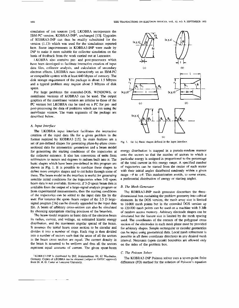
A. Input Integace The LKOBRA input interface facilitates the interactive
creation of the input data file for a given problem in the format required by KOBRA3 [15]. Its main features are a set of pre-defined shapes for generating plane-by-plane cross- sectional data for asymmetric geometries and a beam model for generating the starting conditions of the trajectories at the collector entrance. It also has conversion of units from millimeters to meters and degrees to radians built into it. The basic shapes which have been pre-defined in this program are shown in Fig. 1. It is possible to combine these shapes to define more complex shapes and to cut holes through some of them. The beam model in the interface is useful for generating sensible initial conditions for the trajectories when 3-D spent beam data is not available. However, if 3-D spent-beam data is available from the output of a large-signal analysis program or from experimental measurements, then the starting conditions of the trajectories can be added to the input data file by the user. For instance the spent- beam output of the 2.5 D large- signal program [ 161 can be directly appended to the input data file. A beam of arbitrary cross-section can also be simulated by choosing appropriate starting positions of the beamlets.
The beam model requires as basic data of the electron beam its radius, current, and voltage, an estimated kinetic energy distribution, and the maximum angular spread of the beam. It assumes the initial beam cross section to be circular and divides it into a number of rings. Each ring is then divided into a number of sectors such that the areas of all the sectors in the beam cross section are equal. The current density in the beam is assumed to be uniform and thus all the sectors represent equal amounts of current. The given spent-beam
'KOBRA3-INP is distributed by INP, Junkemstrasse 99, 62 Wiesbaden, Germany. Copies of LKOBRA can be obtained (subject to ESTEC approval) from Dr. R. G. Carter at Lancaster University.
(e)
Fig. 1 . (a)-(e) Basic shapes defined in the input interface.
energy distribution is mapped in a pseudo-random manner onto the sectors so that the number of sectors to which a particular energy is assigned is proportional to the percentage of the total current in this energy range. A specified number of trajectories can be started from the centre of each sector with their initial angles distributed randomly within a given range -0 to +B. This randomization avoids, to some extent, a preferential distribution of energy or starting angles.
B. The Mesh Generator The KOBRA3-INP mesh generator discretises the three-
dimensional box containing the problem geometry into cubical elements. In the DOS version, the mesh array size is limited to 16000 mesh points but in the extended DOS version up to 120000 mesh points can be used on a machine with 5 Mb of random access memory. Arbitrary electrode shapes can be simulated but the feature size is limited by the mesh spacing used. The coordinates of the comers of the polygonal cross section of the electrodes in each mesh plane must be provided for arbitrary shapes. Simple rectangular or circular geometries can be input using geometrical data. Local mesh refinement is possible in all three coordinate directions in any desired mesh interval. Neumann (open circuit) boundries are allowed only on the sides of the problem box.
C. The Poisson Solver
The KOBRA3-INP Poisson solver uses a seven-point finite difference (FD) method for the solution of Poisson's equation
KUMAR er al.: THREE-DIMENSIONAL SIMULATION OF MULTISTAGE DEPRESSED COLLECTORS 1665
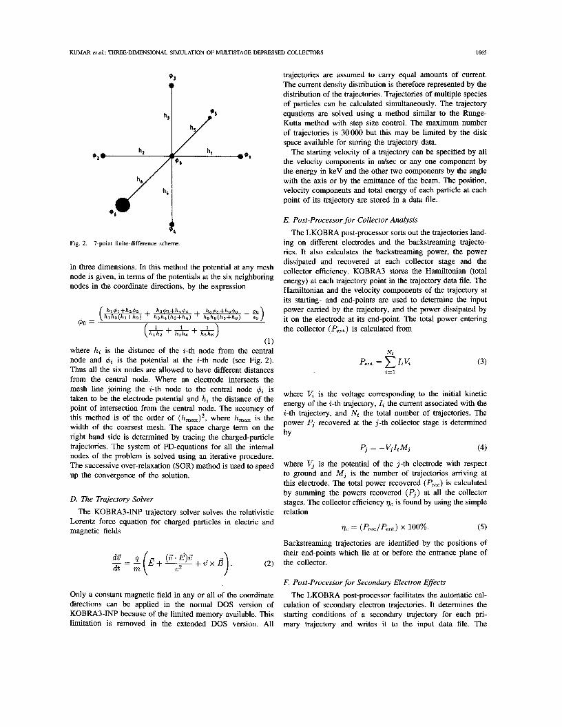
+, Fig. 2. 7-point finite-difference scheme.
in three dimensions. In this methoc. the potential at any mesh node is given, in terms of the potentials at the six neighboring nodes in the coordinate directions, by the expression
hl4l+h2 2 h343+h444 h5 5+h646 ( h l h d h l + L + h3h4(h3+h4) + h5&h5+hd - E) (k+&+&)
$0 =
(1) where hi is the distance of the i-th node from the central node and $i is the potential at the i-th node (see Fig. 2). Thus all the six nodes are allowed to have different distances from the central node. Where an electrode intersects the mesh line joining the i-th node to the central node $i is taken to be the electrode potential and hi the distance of the point of intersection from the central node. The accuracy of this method is of the order of (hm,)', where h,, is the width of the coarsest mesh. The space charge term on the right hand side is determined by tracing the charged-particle trajectories. The system of FD-equations for all the internal nodes of the problem is solved using an iterative procedure. The successive over-relaxation (SOR) method is used to speed up the convergence of the solution.
D. The Trajectory Solver
The KOBRA3-INP trajectory solver solves the relativistic Lorentz force equation for charged particles in electric and magnetic fields
Only a constant magnetic field in any or all of the coordinate directions can be applied in the normal DOS version of KOBRA3-INP because of the limited memory available. This limitation is removed in the extended DOS version. All
trajectories are assumed to carry equal amounts of current. The current density distribution is therefore represented by the distribution of the trajectories. Trajectories of multiple species of particles can be calculated simultaneously. The trajectory equations are solved using a method similar to the Runge- Kutta method with step size control. The maximum number of trajectories is 30000 but this may be limited by the disk space available for storing the trajectory data.
The starting velocity of a trajectory can be specified by all the velocity components in d s e c or any one component by the energy in keV and the other two components by the angle with the axis or by the emittance of the beam. The position, velocity components and total energy of each particle at each point of its trajectory are stored in a data file.
E. Post-Processor for Collector Analysis
The LKOBRA post-processor sorts out the trajectories land- ing on different electrodes and the backstreaming trajecto- ries. It also calculates the backstreaming power, the power dissipated and recovered at each collector stage and the collector efficiency. KOBRA3 stores the Hamiltonian (total energy) at each trajectory point in the trajectory data file. The Hamiltonian and the velocity components of the trajectory at its starting- and end-points are used to determine the input power carried by the trajectory, and the power dissipated by it on the electrode at its end-point. The total power entering the collector (Pent) is calculated from
(3)
where V, is the voltage corresponding to the initial kinetic energy of the i-th trajectory, Ii the current associated with the i-th trajectory, and Nt the total number of trajectories. The power Pj recovered at the j-th collector stage is determined by
Pj = -V,ItMj (4)
where Vj is the potential of the j-th electrode with respect to ground and Mj is the number of trajectories arriving at this electrode. The total power recovered (Prec) is calculated by summing the powers recovered (Pj ) at all the collector stages. The collector efficiency 77, is found by using the simple relation
( 5 )
Backstreaming trajectories are identified by the positions of their end-points which lie at or before the entrance plane of the collector.
~c = (Prec/Pent) x 100%.
F. Post-Processor for Secondary Electron Effects
The LKOBRA post-processor facilitates the automatic cal- culation of secondary electron trajectories. It determines the starting conditions of a secondary trajectory for each pri- mary trajectory and writes it to the input data file. The
1666 IEEE TRANSACTIONS ON ELECTRON DEVICES, VOL. 42, NO. 9, SEPTEMBER 1995
secondary trajectories are then traced using the KOBRA3- INP trajectory solver. The starting points of the secondary trajectories are located at the end-points of the primary tra- jectories. This is not likely to introduce any significant error since these end-points are generally close to the electrode surfaces. A total kinetic energy of 50 eV is assigned to each slow secondary electron which is generally considered as the maximum energy of true secondary electrons. The initial direction of the secondaries is assumed to be normal to the electrode surface since slow electrons are preferentially emitted in that direction. The normal to the electrode surface is determined using the coordinates of the trajectory end- point and the mesh information. In the present version it is not possible to include the space-charge of the secon- daries. This is because the secondary electron trajectories are calculated separately from the primary trajectories and KOBRA3 deletes the space-charge of the previous iteration on restarting the trajectory calculations. It is also not possible to calculate the secondary trajectories simultaneously with the primaries because KOBRA3 does not allow trajectories to have different currents. The influence of the space-charge of the primaries will, however, be present in the potential distribution which is used to determine the electric field for the secondary electron trajectory calculations. Further improvements in KOBRA3 will be carried out to overcome these problems.
G. Post-Processor for Resetting Primary Trajectories
An option has been provided in LKOBRA for restoring all the data related to the primary trajectories after the sec- ondary electron effects processor has been run. However, the secondary electron data is lost on running this processor.
H. Program Output
KOBRA3-INP provides printed and graphical output in forms which are useful for collector simulations. The 3-D display of electrode geometry, mesh and trajectories indi- vidually or together can be viewed from any angle. The geometry and mesh can be displayed in any particular mesh plane or between any two mesh planes. The trajectories can be sorted according to ranges of serial number, initial energy, charge or mass of the particles. 3-D plots of potential surfaces in any mesh plane are available. A 2-D plot option provides plots of geometry, equipotentials and electric field components in any mesh plane. It is also possible to display curves of potential, total energy and kinetic energy components (individual or combined) versus trajectory path length. Sorting of trajectories can also be done in these plots in the same way as in the 3-D plots. Such plots provide very useful insights into the behavior of trajectories in different energy ranges.
The various KOBRA3 program units interact with other units through disk files. This modular structure made it possi- ble for us to develop LKOBRA as an extension of KOBRA3 and made it convenient to control the flow of the program interactively. The package can also be run in batch mode
for a given number of potential and trajectory calculation cycles.
111. VALIDATION OF THE PACKAGE
To validate the package and test its performance for 3-D depressed collector simulation, some simple benchmark tests were performed. The benchmark tests were a beam spread test, to check the accuracy of the space-charge field calculation, and an electron spectrometer test to check the trajectory calculation in given electro- and magneto-static fields. The results of the benchmark tests are discussed in the following sections.
A. Beam Spread Test
The expansion of a cylindrical electron beam in a field- free region under the influence of space-charge forces is given by the universal beam spread curve [17]. According to this a uniform electron beam of radius TO doubles its radius in a distance
L = 0.01207 r~ / (pperv) ' .~
where pperv is the microperveance of the beam. The beam spread test was performed for a beam 1 mm in radius carrying a current of 100 mA at 1 kV (3.1623 pperv). To simulate this problem 100 trajectories representing an electron beam with the above parameters were started at one end of a box with a square cross section. The trajectories were distributed uniformly over the beam cross section. The axis of the beam coincided with the axis of the box. The potential on all sides of the box was held constant at 1 kV. The distance at which the beam radius became twice its initial value was found to be 6.67 mm which agrees well with the theoretical value of 6.78 mm given by (6).
B. Electron Spectrometer Test
The accuracy of the trajectory calculation in itself and in accounting for the bending effect of a magnetic field on an electron can be checked by a very simple electron spectrometer test. In this test a number of trajectories with energies in the range of 0.6-1.3 kV in steps of 0.1 kV were started from a single point in the x-direction in a 14.5 cm cube having a constant potential throughout and a magnetic field of 9.43 Gauss in the z-direction. The agree- ment between the theoretical and computed values of the z-position of the end-points of the trajectories was found to be better than 1%.
Iv . SIMULATION OF AN ASYMMETRIC HYPERBOLIC ELECTRIC FIELD (HEF) COLLECTOR
A four-stage HEF collector, similar to one described by Hechtel [8], was simulated in order to study its general behavior and to demonstrate the capabilities of LKOBRA. In Hechtel's collector the electrodes were hyperbolic in shape and the electron beam was launched off-axis. For the simulation we approximated the hyperbolic shapes of the electrodes by cones with a total collector length of 31.8 mm. The beam
KUMAR et al.: THREE-DIMENSIONAL SIMULATION OF MULTISTAGE DEPRESSED COLLECTORS 1667
I(VNJ&
N
;3 30 v - 5 20 5 > Q c(
10
0 0.4 0.6 0.8 1.0 1.2 1.4
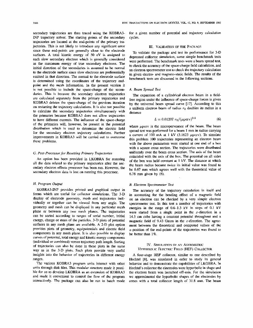
v/vo Fig. 3. Spent beam energy distribution (a) calculated for a high power TWI by a ring model [81, and (b) used for simulation of Hechtel's HEF collector.
0.107 0.271 0.353 0.150 0.017 0.046 0.056
20 55 75 30 5 IO 10
TABLE I SPENT BEAM ENERGY DISTRBUTION USED FOR SIMULATION OF THE HEF COLLECTOR
I VNO 10.55 10.65 10.75 10.85 10.95 11.05 11.15 I
voltage was 24.54 kV and the beam current 3.43 A, which gives a beam perveance of 0.892 pperv. The potentials of the four collector stages were 24.54 kV (body), 12.54 kV, 6.54 kV, and 0.54 kV. The spent beam energy distribution used is shown in Fig. 3 (curve b) and the beam diameter was 1.4 mm. The starting conditions of the trajectories representing the electron beam were generated using the beam model described in Section 11-A. The beam cross section was divided into 41 segments of equal area. Five trajectories were started from the center of each segment with their incident angles randomly distributed in the range -10" to +lo". The total number of trajectories was 205, and these were distributed among various energy ranges by the program (Table I). A self-consistent solution of the problem was obtained in five iterations. A tolerance of 0.1% in collector efficiency was used as a criterion for self-consistency. The average run-time of this problem on an IBM compatible microcomputer (33 MHz, 80386 processor with 80387 Maths co-processor) running under MS-DOS was 105 sec. for the potential solution (50 iterations) and 27 min. for the trajectory calculation for each iteration. The total disk memory requirement for this problem was 10 h4bytes. The complete details of the simulation are given in [13] and [18].
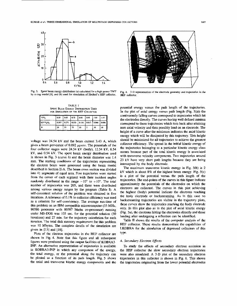
Plots of the electron trajectories in the HEF collector are shown in Fig. 4. Note that this figure and all subsequent figures were produced using the output facilities of KOBRA3- INP. An altemative representation of trajectories is available in KOBRA3-INP in which any component of the energy, the total energy, or the potential along the trajectory can be plotted as a function of its path length. Fig. 5 shows the axial and transverse kinetic energy components and the
Fig. 4. HEF collector.
3-D representation of the electrode geometry and trajectories in the
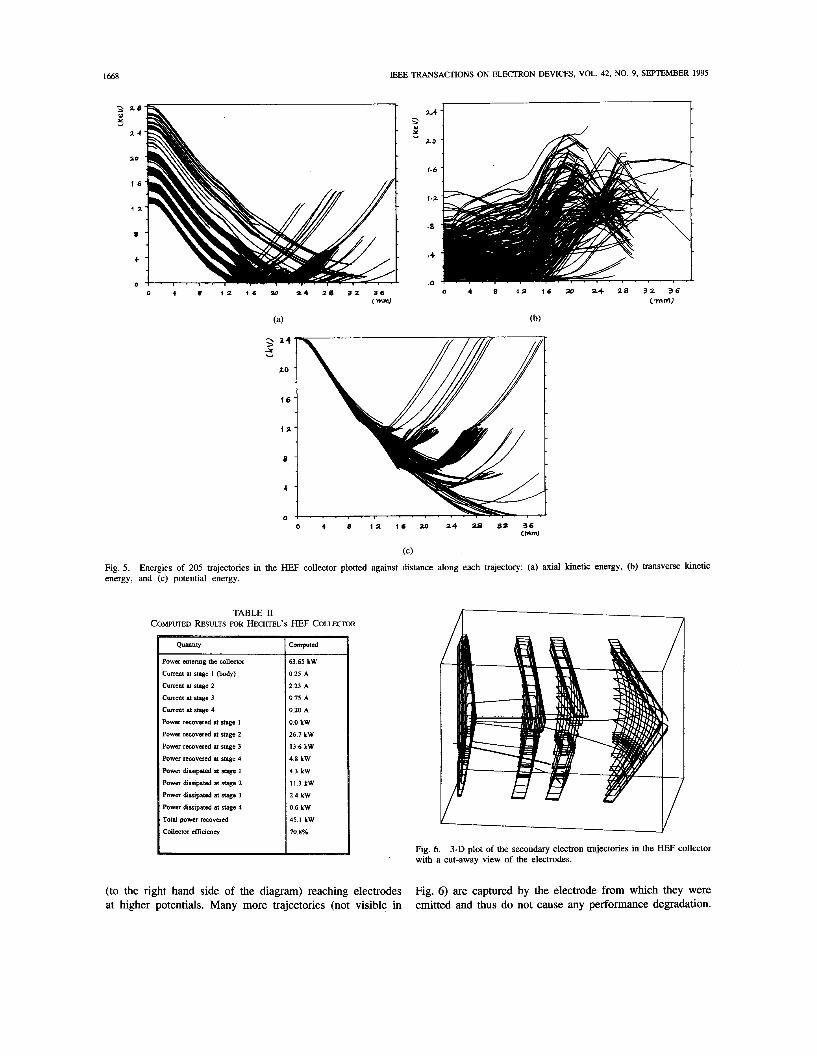
potential energy versus the path length of the trajectories. In the plot of axial energy versus path length (Fig. 5(a)) the continuously falling curves correspond to trajectories which hit the electrodes directly. The curves having well defined minima correspond to those trajectories which turn back after attaining zero axial velocity and then possibly land on an electrode. The height of a curve after the minimum indicates the axial kinetic energy which will be dissipated by this trajectory. This height should be minimized for all trajectories to achieve the greatest collector efficiency. The spread in the initial kinetic energy of the trajectories belonging to a particular kinetic energy class occurs because part of the total kinetic energy is associated with transverse velocity components. Two trajectories around 23 kV have very short path lengths because they are being intercepted by the body electrode.
The maximum transverse kinetic energy in Fig. 5(b) is 2 kV which is about 8% of the highest beam energy. Fig. 5(c) is a plot of the potential versus the path length of the trajectories. The end-points of the curves in this figure indicate approximately the potentials of the electrodes on which the electrons are collected. The curves in this plot achieving the highest (body) potential indicate the electrons reaching the body electrode or backstreaming. As in this case no backstreaming trajectories are visible in the trajectory plots, theFe curves show the trajectories reaching the body electrode only. In this plot also as in the plot of axial kinetic energy (Fig. 5a), the electrons hitting the electrodes directly and those landing after undergoing a reflection can be identified.
Table II shows the results of the computer analysis of the HEF collector. These results demonstrate the capabilities of LKOBRA for the simulation of depressed collectors of this type.
A. Secondary Electron Effects
To study the effects of secondary electron emission in the HEF collector the slow secondary electron trajectories were also simulated. A 3-D plot of the secondary electron trajectories in this collector is shown in Fig. 6. This shows the trajectories originating from the lower potential electrodes
1668 IEEE TRANSACTIONS ON ELECTRON DEVICES, VOL. 42, NO. 9, SEPTEMBER 1995
U 7-A 3 2 8
Y >
2 4 ” - Y Y
2.0
7.0
1.6
1 6
l e 2
1 2
.a E
0 4 + .o
0 4 8 12 I 6 20 14 28 32 36 0”
(C) fig. 5. energy, and (c) potential energy.
Energies of 205 trajectories in the HEF collector plotted against distance along each trajectory: (a) axial kinetic energy, (b) transverse kinetic
TABLE 11 COMPUTED RESULTS FOR HECHTEL’S HEF COLLECTOR
Power eotenng the collector
Current at stage 1 (body)
Current at stage 2
Current at stage 3
Current at stage 4
Power recovered at stage 1
Power rewvered at stage 2
Power recovered at stage 3
Power rewvered at stage 4
Power mwpated at stage I
Power dissipated at stage 2
Power drmpated at stage 3
Power dusipated at stage 4
Total power recovered
Collecmr efficiency
63 65 kW
025 A
223 A
075 A
020 A
0 0 kW
267 kW
13 6 kW
4 8 kW
4 3 kW
11 3 kW
2 4 kW
0 6 kW
45 1 kW
70 8%
(to the right hand side of the diagram) reaching electrodes at higher potentials. Many more trajectories (not visible in
A
Fig. 6. with a cut-away view of the electrodes.
3-D plot of the secondary electron trajectories in the HEF collector
Fig. 6) are captured by the electrode from which they were emitted and thus do not cause any performance degradation.
KUMAR et al.: THREE-DIMENSIONAL SIMULATION OF MULTISTAGE DEPRESSED COLLECTORS 1669
I
I T I
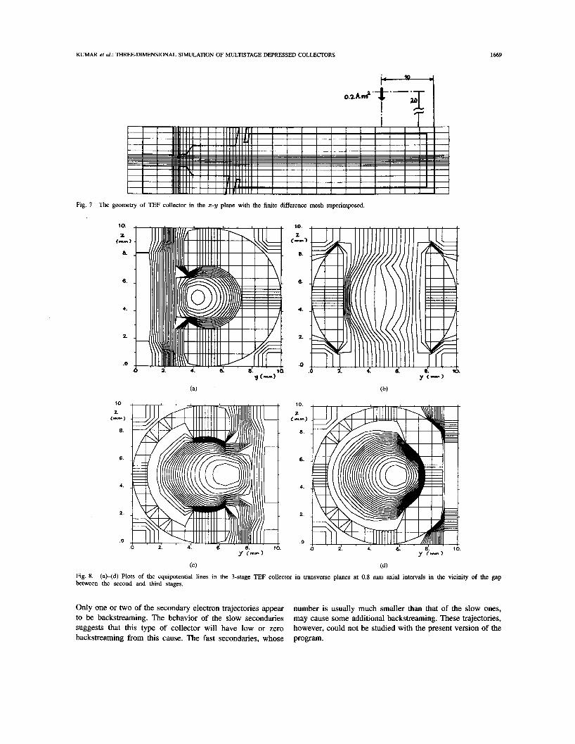
Fig. 7 The geometry of TEF collector in the x-y plane with the finite difference mesh superimposed.
10.
2 (m-)
a
6.
4.
2.
.O
10
z C"1
8.
6 .
4.
2.
.o
10.
1 C--)
8.
6.
4.
2.
0
IO.
z c I*-)
8.
6.
4.
2.
.o
Fig. 8. between the second and third stages.
(aHd) Plots of the equipotential lines in the 3-stage TEF collector in transverse planes at 0.8 mm axial intervals in the vicinity of the gap
Only one or two of the secondary electron trajectories appear to be backstreaming. The behavior of the slow secondaries suggests that this type of collector will have low or zero backstreaming from this cause. The fast secondaries, whose
number is usually much smaller than that of the slow ones, may cause some additional backstreaming. These trajectories, however, could not be studied with the present version of the program.
1670 IEEE
I(VN,,)&
N
TRANSACTIONS ON ELECTRON DEVICES, VOL. 42, NO. 9, SEPTEMBER 1995
0.056 0.430 0.276 0.067 0.078 0.056 0.037
12 78 51 12 15 9 6
TABLE III SPENT BEAM ENERGY DISTRIEWTION Usm FOR SIMULATION OF THE TEF COLLECTOR
I V/V, I 0.55 10.65 I 0.75 I 0.85 I 0.95 I 1.05 I 1.15 I
v . SJMULAnON OF A TILTED ELECTFUC FIELD (TEF) COLLECTOR
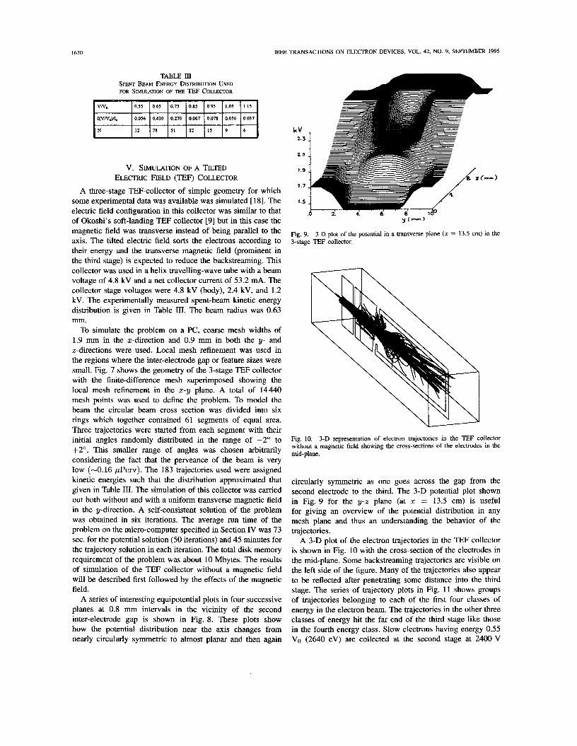
A three-stage TEF-collector of simple geometry for which some experimental data was available was simulated [ 181. The electric field configuration in this collector was similar to that of Okoshi’s soft-landing TEF collector [9] but in this case the magnetic field was transverse instead of being parallel to the axis. The tilted electric field sorts the electrons according to their energy and the transverse magnetic field (prominent in the third stage) is expected to reduce the backstreaming. This collector was used in a helix travelling-wave tube with a beam voltage of 4.8 kV and a net collector current of 53.2 mA. The collector stage voltages were 4.8 kV (body), 2.4 kV, and 1.2 kV. The experimentally measured spent-beam kinetic energy distribution is given in Table 111. The beam radius was 0.63 mm.
To simulate the problem on a PC, coarse mesh widths of 1.9 mm in the %-direction and 0.9 mm in both the y- and z-directions were used. Local mesh refinement was used in the regions where the inter-electrode gap or feature sizes were small. Fig. 7 shows the geometry of the 3-stage TEF collector with the finite-difference mesh superimposed showing the local mesh refinement in the 2-y plane. A total of 14440 mesh points was used to define the problem. To model the beam the circular beam cross section was divided into six rings which together contained 61 segments of equal area. Three trajectories were started from each segment with their initial angles randomly distributed in the range of -2” to +2O. This smaller range of angles was chosen arbitrarily considering the fact that the perveance of the beam is very low (-0.16 pPerv). The 183 trajectories used were assigned kinetic energies such that the distribution approximated that given in Table 111. The simulation of this collector was carried out both without and with a uniform transverse magnetic field in the y-direction. A self-consistent solution of the problem was obtained in six iterations. The average run time of the problem on the micro-computer specified in Section IV was 73 sec. for the potential solution (50 iterations) and 45 minutes for the trajectory solution in each iteration. The total disk memory requirement of the problem was about 10 Mbytes. The results of simulation of the TEF collector without a magnetic field will be described first followed by the effects of the magnetic field.
A series of interesting equipotential plots in four successive planes at 0.8 mm intervals in the vicinity of the second inter-electrode gap is shown in Fig. 8. These plots show how the potential distribution near the axis changes from nearly circularly symmetric to almost planar and then again
kV 2.3
2.1
1.9
I .7
1.5
Fig. 9. 3-stage TEF collector.
3-D plot of the potential in a transverse plane (z = 13.5 cm) in the
Fig. 10. 3-D representation of electron trajectories in the TEF collector without a magnetic field showing the cross-sections of the electrodes in the mid-plane.
circularly symmetric as one goes across the gap from the second electrode to the third. The 3-D potential plot shown in Fig. 9 for the y-z plane (at 2 = 13.5 cm) is useful for giving an overview of the potential distribution in any mesh plane and thus an understanding the behavior of the trajectories.
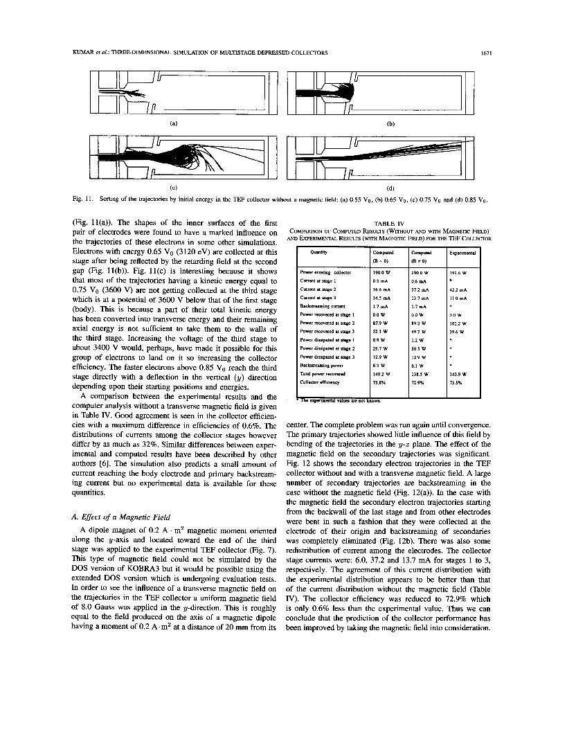
A 3-D plot of the electron trajectories in the TEF collector is shown in Fig. 10 with the cross-section of the electrodes in the mid-plane. Some backstreaming trajectories are visible on the left side of the figure. Many of the trajectories also appear to be reflected after penetrating some distance into the third stage. The series of trajectory plots in Fig. 11 shows groups of trajectories belonging to each of the first four classes of energy in the electron beam. The trajectories in the other three classes of energy hit the far end of the third stage like those in the fourth energy class. Slow electrons having energy 0.55 VO (2640 eV) are collected at the second stage at 2400 V
KUMAR er al.: THREE-DIMENSIONAL SIMULATION OF MULTISTAGE DEPRESSED COLLECTORS 1671
1900 w 0 6 m A
372 mA
137mA
1 7 m A
0 0 w 893 w 4 9 2 W
1 2 w
305 W
1 2 9 W
6 1 W
138 5 W
72 9%
(C) (d) Fig. 11 . Sorting of the trajectories by initial energy in the TEF collector without a magnetic field: (a) 0.55 Vo, (b) 0.65 Vo, ( c ) 0.75 Vo and (d) 0.85 Vo.
191 6 W
422 mA
IlOmA
0 0 w 101 2 w 3 9 6 W
1409 W
73 5%
(Fig. ll(a)). The shapes of the inner surfaces of the first pair of electrodes were found to have a marked influence on the trajectories of these electrons in some other simulations. Electrons with energy 0.65 VO (3120 eV) are collected at this stage after being reflected by the retarding field at the second gap (Fig. 1 l(b)). Fig. 1 l(c) is interesting because it shows that most of the trajectories having a kinetic energy equal to 0.75 VO (3600 V) are not getting collected at the third stage which is at a potential of 3600 V below that of the first stage (body). This is because a part of their total kinetic energy has been converted into transverse energy and their remaining axial energy is not sufficient to take them to the walls of the third stage. Increasing the voltage of the third stage to about 3400 V would, perhaps, have made it possible for this group of electrons to land on it so increasing the collector efficiency. The faster electrons above 0.85 VO reach the third stage directly with a deflection in the vertical (y) direction depending upon their starting positions and energies.
A comparison between the experimental results and the computer analysis without a transverse magnetic field is given in Table IV. Good agreement is seen in the collector efficien- cies with a maximum difference in efficiencies of 0.6%. The distributions of currents among the collector stages however differ by as much as 32%. Similar differences between exper- imental and computed results have been described by other authors [6]. The simulation also predicts a small amount of current reaching the body electrode and primary backstream- ing current but no experimental data is available for these quantities.
A. Effect of a Magnetic Field
A dipole magnet of 0.2 A . m2 magnetic moment oriented along the y-axis and located toward the end of the third stage was applied to the experimental TEF collector (Fig. 7). This type of magnetic field could not be simulated by the DOS version of KOBRA3 but it would be possible using the extended DOS version which is undergoing evaluation tests. In order to see the influence of a transverse magnetic field on the trajectories in the TEF collector a uniform magnetic field of 8.0 Gauss was applied in the y-direction. This is roughly equal to the field produced on the axis of a magnetic dipole having a moment of 0.2 A.m2 at a distance of 20 mm from its
TABLE N COMPARISON OF COMPUTED RESULTS (WITHOUT AND WITH MAGNETIC FIELD)
AND EXPERIMENTAL RESULTS (WITH MAGNETIC FIELD) FOR THE TEF COLLECTOR
QWtitY I Power entenng collector
Backstreaming cunmt
Power recovered m stage 1
Power recovered nt mge 2
Power recovered n stage 3
Power Luipand n stage 1
Power dissipated at stage 2
Power Lmpated n stage 3
Backstreaming power
Total power recovered
Colleeror &icimcy
- Computed
(B = 0)
1 9 0 0 W
0 3 mA
366 mA
I45 mA
1 7 m A
0 0 w 8 7 9 w 523 W
0 9 W
2 9 7 w 1 2 9 W
6 3 W
1402 W
73 8%
D W I
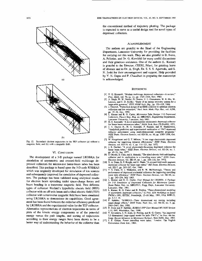
center. The complete problem was run again until convergence. The primary trajectories showed little influence of this field by bending of the trajectories in the y-z plane. The effect of the magnetic field on the secondary trajectories was significant. Fig. 12 shows the secondary electron trajectories in the TEF collector without and with a transverse magnetic field. A large number of secondary trajectories are backstreaming in the case without the magnetic field (Fig. 12(a)). In the case with the magnetic field the secondary electron trajectories starting from the backwall of the last stage and from other electrodes were bent in such a fashion that they were collected at the electrode of their origin and backstreaming of secondaries was completely eliminated (Fig. 12b). There was also some redistribution of current among the electrodes. The collector stage currents were: 6.0, 37.2 and 13.7 mA for stages 1 to 3, respectively. The agreement of this current distribution with the experimental distribution appears to be better than that of the current distribution without the magnetic field (Table IV). The collector efficiency was reduced to 72.9% which is only 0.6% less than the experimental value. Thus we can conclude that the prediction of the collector performance has been improved by taking the magnetic field into consideration.
1672 IEEE TRANSACTIONS ON ELECTRON DEVICES, VOL. 42, NO. 9, SEPTEMBER 1995
(b) Fig. 12. magnetic field, and (b) with a magnetic field.
Secondary electron trajectories in the TEF collector (a) without a
VI. CONCLUSION The development of a 3-D package named LKOBRA for
simulation of asymmetric and crossed-field multistage de- pressed collectors for microwave linear-beam tubes has been described. This package is based upon the 3-D code KOBRA3 which was originally developed for simulation of ion sources and subsequently improved for simulation of depressed collec- tors. The package has been validated using analytical results for electron beam spreading under space-charge forces and beam bending in a transverse magnetic field. Two different types of collector: Hechtel’s hyperbolic electric field (HEF) collector with an off-axis beam and a tilted electric field (TEF) collector with a transverse magnetic field have been simulated using LKOBRA to demonstrate its capabilities. Good agree- ment has been found between the collector efficiency predicted by LKOBRA and the experimental value for the TEF collector. Alternative representations of electron trajectories in terms of plots of the kinetic energy components or of the potential energy versus the path lengths, and sorting of trajectories according to their energy ranges have been shown to be a better way of understanding the behavior of the collector than
the conventional method of trajectory plotting. The package is expected to serve as a useful design tool for novel types of depressed collectors.
ACKNOWLEDGMENT The authors are grateful to the Head of the Engineering
Department, Lancaster University for providing the facilities for carrying out this work. They are also grateful to D. Ivens, A. Pelletier, and Dr. G. Komfeld for many useful discussions and their generous assistance. One of the authors (L. Kumar) is grateful to the Director, CEERI, Pilani, for granting leave of absence and to Dr. A. Singh, Dr. S. S. S. Agarwala, and S. N. Joshi for their encouragement and support. Help provided by Y. N. Gupta and P. Chaudhari in preparing the manuscript is acknowledged.
REFERENCES
[ 11 H. G. Kosmahl, “Modern multistage depressed collectors-A review,” Proc. IEEE, vol. 70, no. 11, pp. 1325-1334, Nov. 1982.
[2] A. Singh, W. W. Destler, D. Goutos, V. L. Granatstein, W. R. Hix, W. Lawson, and C. D. Strifler, “Study of an energy recovery system for a large-orbit gyrotron,” IEEE IEDM Tech. Dig., pp. 155-158, 1988.
[3] J. Dietrich, “Numerical design of an EBIS collector to optimize electron collection and ion extraction,” Nucl. Instr. Meth. Phys. Res., vol. A298, pp. 35-38, Dec. 1990.
[4] L. Kumar and R. G. Carter, Microwave Tube Design: 3 - 0 Depressed Collectors. Phase-I Rep., Rep. no. MRG/90/1, Engineering Department, Lancaster University, Lancaster, July 1991.
[5] H. G. Kosmahl, “A novel axisymmetric electrostatic depressed collector for linear-beam microwave tubes,” NASA Tech. Note TN-D-6093, 1971.
[6] J. A. Dayton Jr., H. G. Kosmahl, P. Ramins, and N. Stankiewicz, “Analytical prediction and experimental verification of TWT depressed collector peformance using multi-dimensional computer programs,” IEEE Trans. Electron Devices, vol. ED-26, no. 10, pp. 1589-1598, Oct. 1979.
[7] W. Neugebauer and G. T. Mihran, “A ten stage electrostatic depressed collector for improving klystron efficiencies,” IEEE Trans. Electron Devices, vol. ED-19, no. 1, pp. 111-121, Jan. 1972.
[8] J. R. Hechtel, “A novel electrostatic-focussing depressed collector for linear beam tubes,” IEEE Trans. Electron Devices, vol. ED-24, no. 1, pp. 45-52, Jan. 1977.
[9] T. Okoshi, E. Chiu, and S. Matsuici, “The tilted electric field soft-landing collector and its application to a travelling-wave tube,” IEEE Trans. Electron Devices, vol. ED-19, no. 1, pp. 104-110, Jan. 1972.
[lo] D. A. Dunn, R. P. Borghi, and G. Wada, “A crossed-field multi-segment depressed collector for beam type tubes,” IRE Trans. Electron Devices,
[ l l ] T. S. Chen, H. J. Wolkstein, and R. W. McMurrough, “Theory and performance of depressed trochoidal collectors for improving travelling wave tube efficiency,” IEEE Trans. Electron Devices, vol. ED-10, no. 7, pp. 243-254, July 1963.
[12] L. Kumar and R. G. Carter, User Manual for LKOBRA: A Package for 3 - 0 Simulation of Depressed Collectors for Microwave Linear- Beam Tubes, Rep. no. MRG/91/1, Engg. Dept., Lancaster University, Lancaster, Mar. 1991.
[13] L. Kumar, R. G. Carter and D. Pening, ‘Three-dimensional modeling of asymmetric depressed collectors,” in Proc. ESA Workshop on Space TWTA’s 1991, ESTEC, Noordwijk, 15-16 May, 1991, ESA WPP-22, pp. 6.3.1-18.
[ 141 P. Spadtke, “KOBRA3-We dimensional ray tracing including svacecharse effects.” IEEE Trans. Nucl. Sei., vol. NS-32, no. 5 , DD.
vol. ED-7, pp. 262-267, Oct. 1960.
_ _ i465-2467: Oct. 1985.
1151 D. Ivens and P. Svikltke, KOBRA3-INP User Manual MS-DOS Version - - 1.13, I”, Wiesbaden, Dec. 1990.
[16] V. Srivastava, S. N. Joshi, D. Pemng, and R. G. Carter, “An improved 2.5 dimensional large-signal model for helix TWT’s,” in Proc. 4th Int. Symp. Recent Advances in Microwave Technol., New Delhi, Dec. 1993.
[17] J. F. Gittins, Power travelling wave tubes. London: The English Universities Press Ltd., 1964.
KUMAR et al.: THREE-DIMENSIONAL SIMULATION OF MULTISTAGE DEPRESSED COLLECTORS 1673
[18] L. Kumar and R. G. Carter, Microwave Tube Design: 3 - 0 Depressed Collectors, Report MRG/91/2, Engineering Department, Lancaster Uni- versity, Oct. 1991.
Lalit Kumar obtained the M.Sc. degree in physics from Meerut University, Meerut, in 1973 and the Ph.D. degree in physics from Birla Institute of Technology & Science, Pilani, India, in 1980 for his studies on radiation from plasma columns excited by circularly symmetric em. sources.
He joined the Central Electronics Engineering Research Institute, Pilani, as a Scientist in I978 where he is currently working as Project Leader of Helix TWT development project and is associated with Gyrotron development. He has been earlier
engaged on design and development of a TWT and a coaxial magnetron. From 1983 to 1985, he was a DAAD Fellow in Germany and worked at the Institute of Applied Physics, University of Tuebingen, on development of a code for electron gun simulation, and at Valvo (Philips), Hamburg, on problems related to the Gyrotron. He was an Hon. Visiting Research Fellow at the Engineering Department, Lancaster University, UK, during 1990-1991 and for three months in 1994, where be worked on modeling and design of asymmetric multistage depressed collectors, and a status review of interaction theory for space TWT's. His current interests include computer aided design of electron guns and collectors, broadbanding, and special fabrication techniques for TWT's and Gyrotrons.
He is a Fellow of the Institution of Electronics & Telecommunication Engineers, India, and a member of the Indian Physics Association and the Indian Vacuum Society.
P. Spiidtke, born on May 2, 1953. He attended col- lege in Wiesbaden from 1977 to 1980, and received the Diplom Ingenieur Physikalische technik degree.
Since 1980, he has been with Gesellshaft fiir Schwerionen Forschung, Darmstadt, Gemany.
R. G. Carter graduated in physics from the Univer- sity of Cambridge in 1965 and received the Ph.D. degree from the University of Wales in 1968 for work on the propagation of waves on neutralised ion beams.
From 1968 to 1972 he worked on high power travelling-wave tubes as a Development Engineer at English Electric Valve Co. Ltd. He joined the Department of Engineering, the University of Lan- caster, as a Lecturer in 1972, and was promoted to Senior Lecturer in 1986. He is the leader of the
Microwave Research Group in the Department of Engineering and Director of the Continuing Education Unit. His research interests include electromagnetics and microwave engineering with particular reference to the theory, design, and computer modeling of microwave tubes. He is the author of a number of papers, two textbooks on electromagnetics, and a set of video lectures on microwave tubes.
D. Perring was born in England in August 1940. He graduated from London University in 1964 with a B.S. degree in mathematics and physics.
He gained the majority of his industrial experience at THORN EM-Varian where he was responsible for the design and development of microwave tubes. In 1984, he was appointed as a Staff Member of the European Space Agency Research and Technology Centre where he was responsible for space travelling wave tube amplifiers. He had a number of papers and patents in the field of microwave tube amplifiers and was a member of many learned committees.
Related Documents