CentriMag ® Back-Up Console OPERATING MANUAL Distributed By: 6035 Stoneridge Drive Pleasanton, CA 94588 USA Tel: 925/847-8600 Fax: 925/847-8574 www.thoratec.com Emergency HeartLine™ USA: 800/456-1477 Manufactured By: Levitronix, Zurich, Switzerland PL-0075 Rev. 00 September 2006

Welcome message from author
This document is posted to help you gain knowledge. Please leave a comment to let me know what you think about it! Share it to your friends and learn new things together.
Transcript
CentriMag® Back-Up Console
OPERATING MANUAL
Distributed By:
6035 Stoneridge Drive Pleasanton, CA 94588 USA Tel: 925/847-8600 Fax: 925/847-8574 www.thoratec.com Emergency HeartLine™ USA: 800/456-1477
Manufactured By: Levitronix, Zurich, Switzerland PL-0075 Rev. 00 September 2006

TABLE OF CONTENTS
1 MANUAL OVERVIEW....................................................................................... 4
2 GENERAL CONVENTIONS ............................................................................... 5
2.1 Warnings and Cautions ................................................................................ 5
2.2 Patents and Trademarks .............................................................................. 5
2.3 Conventions Used in This Manual ................................................................ 5
3 ABOUT THE CENTRIMAG BACK-UP CONSOLE ............................................ 6
3.1 Description.................................................................................................... 7
3.2 Indications for Use...................................................................................... 14
3.3 Contraindications for Use ........................................................................... 14
3.4 Required User Supplied Items.................................................................... 15
4 SPECIFICATIONS AND GENERAL DESCRIPTION ....................................... 16
4.1 Classification .............................................................................................. 16
4.2 Specifications ............................................................................................. 16
4.3 Environmental Conditions........................................................................... 17
4.4 EMI Considerations .................................................................................... 17
4.5 Permanent Magnet Considerations ............................................................ 17
4.6 Transportability ........................................................................................... 18
4.7 Front (Operator Control) Panel ................................................................... 19
4.8 Digital Display Information .......................................................................... 23
4.9 Power Assembly......................................................................................... 25
5 SETTING UP ..................................................................................................... 26
5.1 Unpacking................................................................................................... 26
5.2 Installing the Battery Module ...................................................................... 26
5.3 Powering Up ............................................................................................... 28
5.4 Self-Test Initiation....................................................................................... 28
5.5 Language Selection.................................................................................... 30
5.6 Blood Pump Set-up .................................................................................... 30
CentriMag Back-Up Console Operating Manual Page 2 of 54 © 2006 Thoratec Corporation – Document No. PL-0075, Rev. 00 (September 2006)

6 OPERATING .................................................................................................... 31
6.1 Operation of the Blood Pump ..................................................................... 31
6.2 Special Alarm Stop ..................................................................................... 33
6.3 Alarms and Alerts ....................................................................................... 34
6.4 Alarms ........................................................................................................ 37
6.5 Alerts .......................................................................................................... 38
6.6 Battery Operation ....................................................................................... 38
6.7 Battery Module Replacement ..................................................................... 42
7 MAINTENANCE ................................................................................................ 44
7.1 Changing Fuses ......................................................................................... 44
7.2 Maintenance Following Each Patient Use .................................................. 44
7.3 Recommended Preventive Maintenance.................................................... 45
8 EMERGENCY................................................................................................... 46
8.1 Switching to another Console and Motor .................................................... 46
8.2 Switching to another Motor ......................................................................... 47
8.4 Switching to another Blood Pump............................................................... 48
8.5 Defibrillation/ Cardioversion........................................................................ 48
9 DISPOSAL OF EQUIPMENT ........................................................................... 50
10 APPENDIX I – ALARM/ALERT TABLE........................................................... 51
11 APPENDIX II – TECHNICAL SPECIFICATION ............................................... 52
12 APPENDIX III – SIMILARITIES & DIFFERENCES BETWEEN PRIMARY &
BACK-UP CONSOLE ...................................................................................... 54
CentriMag Back-Up Console Operating Manual Page 3 of 54 © 2006 Thoratec Corporation – Document No. PL-0075, Rev. 00 (September 2006)
1 Manual Overview Section 1: Manual Overview describes the organization of this Manual. Section 2: General Conventions describes warnings, cautions, and
conventions of expression used in this Manual. Section 3: About the CentriMag Back-Up Console describes the general use
of the Back-Up Console. Section 4: Specifications and General Description describes the product
specifications and physical attributes of the Back-Up Console. Section 5: Setting up describes the procedure for unpacking the Back-Up
Console and configuring it for use. Section 6: Operating describes how to operate the Back-Up Console. Section 7: Maintenance describes procedures for maintaining and cleaning the
Back-Up Console. Section 8: Emergency describes procedures for defibrillation and equipment
malfunction. Section 9: Disposal of Equipment describes the procedure for proper disposal
of used Console batteries and Back-Up Consoles that have reached the end of useful service life.
Appendix I: Alarm/Alert Table lists the Back-Up Console’s audio/visual alarms
and alerts and the expected system and operator response to each alarm or alert condition.
Appendix II: Technical Specification lists the product specifications and physical
attributes for the CentriMag Back-Up Console and the Battery Module.
Appendix III: Similarities & Differences Between the Primary & Back-Up
Consoles compares key functions and attributes of the CentriMag Primary Console to the CentriMag Back-Up Console.
CentriMag Back-Up Console Operating Manual Page 4 of 54 © 2006 Thoratec Corporation – Document No. PL-0075, Rev. 00 (September 2006)

2 General Conventions
2.1 Warnings and Cautions Read and observe all WARNINGS listed in this Manual and observe relevant instructions and safety precautions throughout operation of the CentriMag Back-Up Console.
WARNING
Warnings are used to prevent misuse of the device, ensure patient safety, or when special care should be exercised to prevent improper operation of the device which may potentially harm the patient.
CAUTION
Cautions are used to alert the user to exercise special care for the safe and effective use of the device.
Warnings are located within the text of the subject matter to which the warning relates. For this reason, some of the Warnings are included in more than one section. 2.2 Patents and Trademarks Patents: One or more U.S. patents, including U.S. Patent Number 6,100,618, cover this product and its use. Trademarks: Thoratec® is a registered trademark and HeartLine™ is a trademark of Thoratec Corporation. Levitronix® and CentriMag® are registered trademarks of Levitronix LLC. 2.3 Conventions Used in This Manual Switches, keypads and connections on the Back-Up Console are indicated in NORMAL FACE TYPE IN UPPER CASE (e.g., POWER, STOP). Back-Up Console displays are indicated in BOLD FACE TYPE IN UPPER CASE (e.g., SET SPEED, INCREASE, DECREASE, ON BATTERY). The first letter in the name of each system component is capitalized (e.g., Blood Pump, Motor, and Back-Up Console).
CentriMag Back-Up Console Operating Manual Page 5 of 54 © 2006 Thoratec Corporation – Document No. PL-0075, Rev. 00 (September 2006)

3 About the CentriMag Back-Up Console
WARNING
Read this Manual as well as the CentriMag Primary Console Manual before using the CentriMag Back-Up Console with the CentriMag BLOOD PUMP. Thoratec requires users to undergo in-service training prior to use of the Thoratec CentriMag Primary or Back-Up Console.
WARNING
The CentriMag Back-Up Console is designed to be operated only with the CentriMag Blood Pump. There are no safety or performance data that establish compatibility with any other manufacturer’s device or components.
WARNING
A Back-Up Console and Motor are required in the immediate vicinity of the patient whenever the CentriMag System is used. The Back-Up Console and Motor must be plugged in and available should the Primary Console experience a malfunction.
WARNING
The CentriMag Back-Up Console is not designed to replace the Primary Console but to serve as an emergency Back-Up unit for temporary support if the Primary Console has malfunctioned or is suspected to have malfunctioned. The patient must be returned to the Primary Console as soon as the malfunction has been resolved or a new Primary Console becomes available.
CentriMag Back-Up Console Operating Manual Page 6 of 54 © 2006 Thoratec Corporation – Document No. PL-0075, Rev. 00 (September 2006)
WARNING
The CentriMag Back-Up Console does not incorporate flow and pressure measurement capability. Because flow, and in some instances pressure measurements are critical for determining appropriate support levels, flow and pressure levels are to be monitored when the CentriMag Back-Up console is in use. Monitor the flow by employing an independent ultrasonic flow meter and probe comparable to the Transonic Flow Meter and Transonic XL Series Flow Probe. Pressure may be monitored using a pressure transducer with properties comparable to the Becton Dickenson Pressure Transducer DTX-Plus Series which is used with the CentriMag Primary Console. The CentriMag Back-Up Console should be exchanged for a replacement Primary Console as soon as possible.
3.1 Description
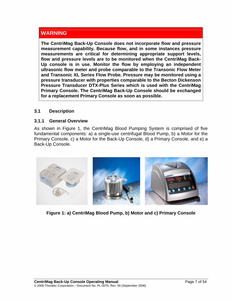
3.1.1 General Overview As shown in Figure 1, the CentriMag Blood Pumping System is comprised of five fundamental components: a) a single-use centrifugal Blood Pump, b) a Motor for the Primary Console, c) a Motor for the Back-Up Console, d) a Primary Console, and e) a Back-Up Console.
Figure 1: a) CentriMag Blood Pump, b) Motor and c) Primary Console
CentriMag Back-Up Console Operating Manual Page 7 of 54 © 2006 Thoratec Corporation – Document No. PL-0075, Rev. 00 (September 2006)

Figure 1d: CentriMag Back-Up Console The CentriMag Primary Console is a fully functional Drive Console, equipped with flow and pressure sensing and display capability. The patient is to be supported with the Primary Console at all times unless there is a malfunction or failure necessitating exchanging the CentriMag Primary Console for a CentriMag Back-Up Console. The intended function of the CentriMag Back-Up Console is to provide basic life-support during a Primary Console malfunction until the Primary Console can be replaced with another Primary Console. The CentriMag Back-Up Console hardware and application software were modeled after the existing CentriMag Primary Console and are functionally the same as the existing CentriMag Primary Console. However, the CentriMag Back-Up Console does not have flow and pressure sensing capability.
3.1.2 Technology Overview The Thoratec CentriMag Blood Pump is an electronically driven, centrifugal Pump based on bearingless electric motor technology. The bearingless centrifugal Pump allows Pumping without mechanical bearings and seals. The basic principle is shown in Figure 2. A rotor is floating and rotating in the magnetic fields of a stator without mechanical contact. A compact digital signal processor system with a servo amplifier allows precise regulation of the speed.
CentriMag Back-Up Console Operating Manual Page 8 of 54 © 2006 Thoratec Corporation – Document No. PL-0075, Rev. 00 (September 2006)

inletpump housing
impeller
outlet
rotor
winding
stator
Figure 2: Schematic with the basic principle of the bearingless centrifugal
Pump
External position sensors actively control the radial rotor position. Processor-controlled electronics regulate the magnetic fields so that the rotor is always centered. The electronics also allow precise regulation of the radial rotor position and the speed. Axial position and tilting of the rotor are passively stabilized (Figure 3). Only the non-contact rotor floats in the Blood Pump and is levitated by magnetic fields through its walls.
ω F a) F
F z F zF r Fr
ω
Fk
Fz
Fr
F M
F F z
r
b)
Figure 3: Axial support (a) and stabilization against tilting (b) of the rotor by passive magnetic forces in the CentriMag BLOOD PUMP
CentriMag Back-Up Console Operating Manual Page 9 of 54 © 2006 Thoratec Corporation – Document No. PL-0075, Rev. 00 (September 2006)

3.1.2 System
3.1.2.1 CentriMag System Components The components listed in Table 1 comprise the CentriMag System. When a patient is supported on the Primary System, the Back-Up System must be available in the immediate vicinity of the patient at all times.
Table 1: Primary & Back-Up Elements of the CentriMag System
System Component Primary System Back-Up System
CentriMag Blood Pump CentriMag Primary Console CentriMag Motor CentriMag Flow Probe CentriMag Back-Up Console CentriMag Back-Up Console Battery Module 3.1.2.2 Optional CentriMag System Components The following components are available as accessories to the CentriMag System:
Table 2: Optional Elements of the CentriMag System
System Component Available for the Primary System
Available for the Back-Up System
CentriMag Battery Module CentriMag Console Cart CentriMag Portable Stand CentriMag Motor Holster CentriMag Pressure Transducer Cables CentriMag Pressure Transducers 3.1.3 CentriMag Back-Up Console The CentriMag Back-Up Console uses single phase AC power and is capable of a flow rate of up to 9.9 LPM or maximum pressure head of 600 mmHg. In addition each Back-Up Console contains a non-rechargeable, field replaceable internal battery that is capable of maintaining Back-Up Console functionality in the event of a loss of AC Power.
CentriMag Back-Up Console Operating Manual Page 10 of 54 © 2006 Thoratec Corporation – Document No. PL-0075, Rev. 00 (September 2006)

3.1.3.1 CentriMag Back-Up Console Front Panel The Thoratec CentriMag Back-Up Console (Figure 4) is a microprocessor-based device. The microprocessor generates the primary Motor control signal, monitors system sensors, generates front display outputs, and provides alarm functions. The microprocessor acquires the sensor data for use in generating operator displays and alarms. An alphanumeric screen is used to display monitored data.
Figure 4: Thoratec CentriMag Back-Up Console
3.1.3.2 CentriMag Back-Up Console Back Panel The CentriMag Back-Up Console back panel (Figure 5) contains the required mechanical inputs and outputs needed to operate a CentriMag Blood Pump.
Figure 5: Back panel - Thoratec CentriMag Back-Up Console
CentriMag Back-Up Console Operating Manual Page 11 of 54 © 2006 Thoratec Corporation – Document No. PL-0075, Rev. 00 (September 2006)

3.1.4 CentriMag Blood Pump The Thoratec CentriMag Blood Pump (Figure 6) is a sterile, single-use, disposable, Centrifugal Blood Pump that has a spinning impeller which imparts rotary motion to the incoming blood, directing it through the outlet port. The Pump is designed to move blood by centrifugal force created by the rotating impeller. The system is designed to allow improved blood handling and to decrease trauma by magnetically levitating the impeller and by eliminating seals and bearings.
Figure 6: CentriMag Blood Pump
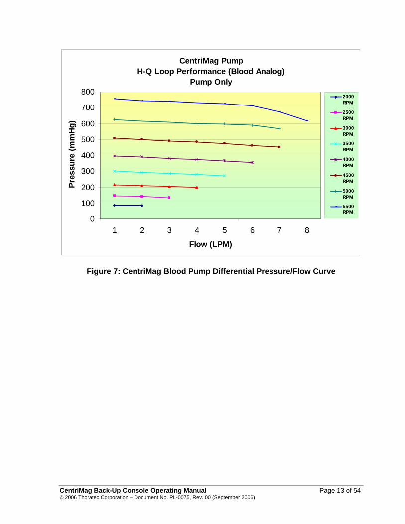
Blood enters the Pump and is accelerated through the actions of the rotating impeller. The flow rate is dependant on the available amount of blood to be pumped, the Pump speed (RPM), and the arterial pressure. The relationship between pressure and flow rate as a function of RPM can be seen in Figure 7 for the CentriMag Blood Pump (as an isolated component).
CentriMag Back-Up Console Operating Manual Page 12 of 54 © 2006 Thoratec Corporation – Document No. PL-0075, Rev. 00 (September 2006)
CentriMag Pump H-Q Loop Performance (Blood Analog)
Pump Only
0
100
200
300
400
500
600
700
800
1 2 3 4 5 6 7 8
Flow (LPM)
Pres
sure
(mm
Hg)
2000RPM
2500RPM
3000RPM
3500RPM
4000RPM
4500RPM
5000RPM
5500RPM
Figure 7: CentriMag Blood Pump Differential Pressure/Flow Curve
CentriMag Back-Up Console Operating Manual Page 13 of 54 © 2006 Thoratec Corporation – Document No. PL-0075, Rev. 00 (September 2006)

3.1.5 CentriMag Motor The Thoratec CentriMag Motor (Figure 8) holds the CentriMag disposable Blood Pump and drives the rotor inside the Blood Pump.
Figure 8: CentriMag Motor
This Manual describes the functions, setup and operation of the CentriMag Back-Up Console. A more complete description of the setup and priming of the Blood Pump can be found in the Thoratec CentriMag Blood Pump Instructions for Use.
3.2 Indications for Use Thoratec CentriMag Blood Pump is indicated to pump blood through the extracorporeal bypass circuit for extracorporeal circulatory support for periods appropriate to cardiopulmonary bypass (up to six hours). It is also indicated for use in extracorporeal circulatory support systems (for periods up to six hours) not requiring complete cardiopulmonary bypass (e.g., valvuloplasty, circulatory support during mitral valve reoperation, surgery of the vena cava or aorta, liver transplants etc). 3.3 Contraindications for Use This CentriMag System is contraindicated for use as a cardiotomy suction device. It is also contraindicated for patients who are unable or unwilling to be treated with appropriate anticoagulation such as Heparin.
CentriMag Back-Up Console Operating Manual Page 14 of 54 © 2006 Thoratec Corporation – Document No. PL-0075, Rev. 00 (September 2006)

3.4 Required User Supplied Items The following items, required for use with the CentriMag System, are necessary but not provided by Thoratec: • Smooth-Jawed Tubing clamps capable of effectively clamping thick-walled 3/8”
Tubing • Hemostats or vascular clamps • Connecting tubing and adaptors • Oxygenator • Circuit prime • Circuit filter • tubing adapters with luer lock ports
CentriMag Back-Up Console Operating Manual Page 15 of 54 © 2006 Thoratec Corporation – Document No. PL-0075, Rev. 00 (September 2006)
4 Specifications and General Description This section includes the product specifications and physical attributes of the Back-Up Console.
4.1 Classification
Table 3: Back-Up Console Classification
SYMBOL CLASSIFICATION DESCRIPTION
Type CF – Defibrillator Proof Equipment Type.
None Class 1 Equipment Classification. None Continuous, internally powered Mode of Operation.
None Not for AP or APG. Not suitable for use in the presence of a flammable anesthetic mixture.
None IPX0 enclosure.
Not splash proof. Do not spray cleaning agents directly on Back-Up Console enclosure.
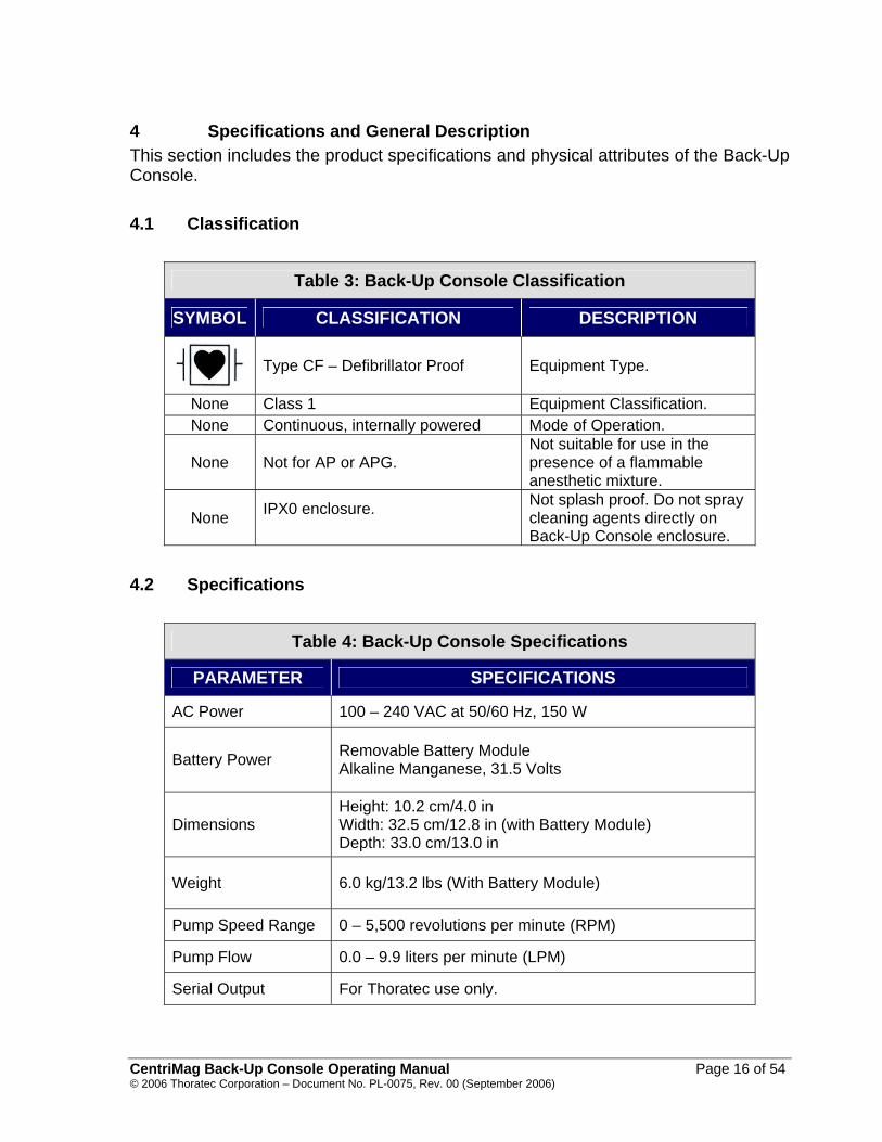
4.2 Specifications
Table 4: Back-Up Console Specifications
PARAMETER SPECIFICATIONS
AC Power 100 – 240 VAC at 50/60 Hz, 150 W
Battery Power Removable Battery Module Alkaline Manganese, 31.5 Volts
Dimensions Height: 10.2 cm/4.0 in Width: 32.5 cm/12.8 in (with Battery Module) Depth: 33.0 cm/13.0 in
Weight 6.0 kg/13.2 lbs (With Battery Module)
Pump Speed Range 0 – 5,500 revolutions per minute (RPM)
Pump Flow 0.0 – 9.9 liters per minute (LPM)
Serial Output For Thoratec use only.
CentriMag Back-Up Console Operating Manual Page 16 of 54 © 2006 Thoratec Corporation – Document No. PL-0075, Rev. 00 (September 2006)
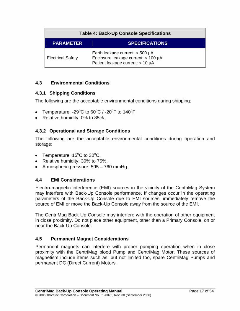
Table 4: Back-Up Console Specifications
PARAMETER SPECIFICATIONS
Electrical Safety Earth leakage current: < 500 µA Enclosure leakage current: < 100 µA Patient leakage current: < 10 µA
4.3 Environmental Conditions
4.3.1 Shipping Conditions The following are the acceptable environmental conditions during shipping: • Temperature: -29oC to 60oC / -20oF to 140oF • Relative humidity: 0% to 85%. 4.3.2 Operational and Storage Conditions The following are the acceptable environmental conditions during operation and storage: • Temperature: 15oC to 30oC. • Relative humidity: 30% to 75%. • Atmospheric pressure: 595 – 760 mmHg. 4.4 EMI Considerations Electro-magnetic interference (EMI) sources in the vicinity of the CentriMag System may interfere with Back-Up Console performance. If changes occur in the operating parameters of the Back-Up Console due to EMI sources, immediately remove the source of EMI or move the Back-Up Console away from the source of the EMI. The CentriMag Back-Up Console may interfere with the operation of other equipment in close proximity. Do not place other equipment, other than a Primary Console, on or near the Back-Up Console. 4.5 Permanent Magnet Considerations Permanent magnets can interfere with proper pumping operation when in close proximity with the CentriMag blood Pump and CentriMag Motor. These sources of magnetism include items such as, but not limited too, spare CentriMag Pumps and permanent DC (Direct Current) Motors.
CentriMag Back-Up Console Operating Manual Page 17 of 54 © 2006 Thoratec Corporation – Document No. PL-0075, Rev. 00 (September 2006)

4.6 Transportability As shown in Figure 9, The CentriMag Back-Up Console is designed to be transported with the Primary Console. The Primary Console should always be the default Console used to support the patient. The Back-Up Console is only provided to function as an emergency Back-Up unit should the Primary Console malfunction. The Back-Up Console should be mounted beneath the Primary Console. In this configuration, the handle on the Primary Console may be used to carry and lift both units. The Primary and Back-Up Consoles may be connected to a portable stand (Figure 9a), or placed on a CentriMag Cart (Figure 9b) so that the units can be rolled together during transport.
WARNING
The CentriMag Back-Up Console is not designed to replace the Primary Console but to serve as an emergency Back-Up unit for temporary support if the Primary Console has malfunctioned or is suspected to have malfunctioned. The patient must be returned to the Primary Console as soon as the malfunction has been resolved or a replacement Primary Console becomes available.
Figure 9a: Primary & Back-Up Console Mounted on Portable Stand
CentriMag Back-Up Console Operating Manual Page 18 of 54 © 2006 Thoratec Corporation – Document No. PL-0075, Rev. 00 (September 2006)

Figure 9b: Primary & Back-Up Console Mounted on CentriMag Console Cart
4.7 Front (Operator Control) Panel To facilitate ease of use, the CentriMag Back-Up Console Front Panel (10b) has a similar appearance to that of the CentriMag Primary Console Front Panel (Figure 10a). The CentriMag Back-Up Console provides the same maximal speed and flow capabilities as the Primary Console, but does not have flow (LPM) or pressure measurement capability. The Back-Up Console also does not have a battery gauge display on the Front Panel Overlay but does provide “Battery Time Remaining” on the digital display window. The CentriMag Back-Up Console Front Panel (Figure 10b) contains a VFT (vacuum fluorescent) display with two rows of 24 characters each. Row 1 includes information including Set Speed and Actual speed. Row 2 contains information about alarm and alert status.
CentriMag Back-Up Console Operating Manual Page 19 of 54 © 2006 Thoratec Corporation – Document No. PL-0075, Rev. 00 (September 2006)

Row 3 consists of five keypad buttons. The first keypad (furthest to the left) silences the alarm audio, and the last one on the right stops the Blood Pump. The other three keypads from left to right include: Blood Pump Set Speed adjustment (SET SPEED) and the next two to the right either increase or decrease the Speed adjustment, or scroll through alarm or alert condition adjustments (DECREASE) (INCREASE).
Figure 10a – CentriMag (Primary) Console Front Panel Overlay
Figure 10b – CentriMag Back-Up Console Front Panel Overlay
CentriMag Back-Up Console Operating Manual Page 20 of 54 © 2006 Thoratec Corporation – Document No. PL-0075, Rev. 00 (September 2006)
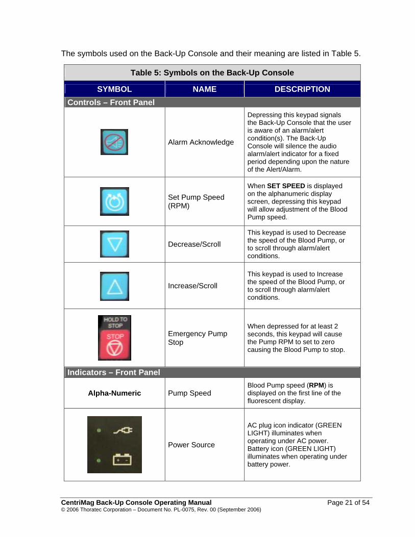
The symbols used on the Back-Up Console and their meaning are listed in Table 5.
Table 5: Symbols on the Back-Up Console
SYMBOL NAME DESCRIPTION Controls – Front Panel
Alarm Acknowledge
Depressing this keypad signals the Back-Up Console that the user is aware of an alarm/alert condition(s). The Back-Up Console will silence the audio alarm/alert indicator for a fixed period depending upon the nature of the Alert/Alarm.
Set Pump Speed (RPM)
When SET SPEED is displayed on the alphanumeric display screen, depressing this keypad will allow adjustment of the Blood Pump speed.
Decrease/Scroll
This keypad is used to Decrease the speed of the Blood Pump, or to scroll through alarm/alert conditions.
Increase/Scroll This keypad is used to Increase the speed of the Blood Pump, or to scroll through alarm/alert conditions.
Emergency Pump Stop
When depressed for at least 2 seconds, this keypad will cause the Pump RPM to set to zero causing the Blood Pump to stop.
Indicators – Front Panel
Alpha-Numeric Pump Speed Blood Pump speed (RPM) is displayed on the first line of the fluorescent display.
Power Source
AC plug icon indicator (GREEN LIGHT) illuminates when operating under AC power. Battery icon (GREEN LIGHT) illuminates when operating under battery power.
CentriMag Back-Up Console Operating Manual Page 21 of 54 © 2006 Thoratec Corporation – Document No. PL-0075, Rev. 00 (September 2006)
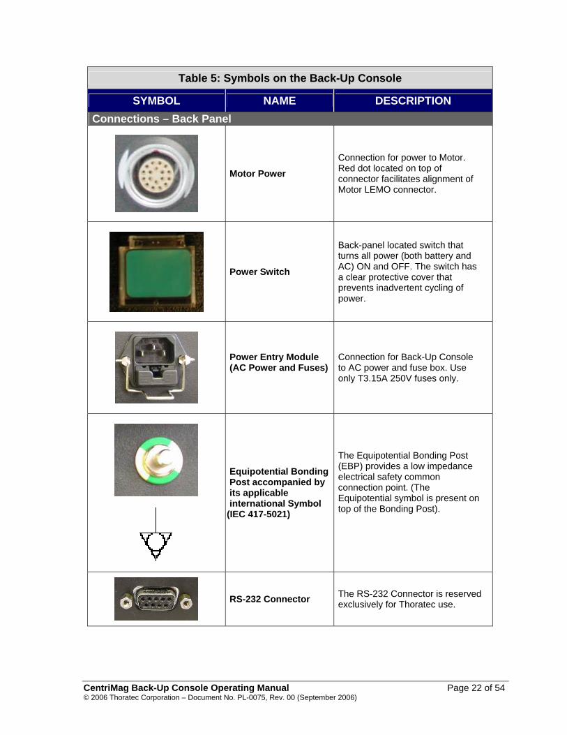
Table 5: Symbols on the Back-Up Console
SYMBOL NAME DESCRIPTION Connections – Back Panel
Motor Power Connection for power to Motor. Red dot located on top of connector facilitates alignment of Motor LEMO connector.
Power Switch
Back-panel located switch that turns all power (both battery and AC) ON and OFF. The switch has a clear protective cover that prevents inadvertent cycling of power.
Power Entry Module (AC Power and Fuses)
Connection for Back-Up Console to AC power and fuse box. Use only T3.15A 250V fuses only.
Equipotential Bonding Post accompanied by its applicable international Symbol
(IEC 417-5021)
The Equipotential Bonding Post (EBP) provides a low impedance electrical safety common connection point. (The Equipotential symbol is present on top of the Bonding Post).
RS-232 Connector The RS-232 Connector is reserved exclusively for Thoratec use.
CentriMag Back-Up Console Operating Manual Page 22 of 54 © 2006 Thoratec Corporation – Document No. PL-0075, Rev. 00 (September 2006)

Table 5: Symbols on the Back-Up Console
SYMBOL NAME DESCRIPTION Serial Number Label
Serial Number Identifies the serial number of the
CentriMag Back-Up Console.
Date of Manufacture
Specifies the date of manufacture of the CentriMag Back-Up Console.
Catalog Number Thoratec Catalog Number
Defibrillation-proof Type CF Equipment Equipment type.
Caution
Consult Thoratec CentriMag Back-Up Console Operating Manual before operating the device.
4.8 Digital Display Information The alphanumeric digital display provides messages and information on system settings and alarms/alerts once the Console has successfully powered up. The digital display allows the user to start/stop the Pump, view system status and Pump speed. The display is divided into two lines with a maximum of 24 characters per line. The top line (line 1) indicates the system status and also provides the ability to modify the set speed. The bottom line (line 2) provides the ability to view the system’s active fault messages and the Set Pump Speed Screen when a change in speed is requested. The Back-Up Console has the ability to display 18 groups of system messages. These digitally displayed messages are described in table 6 below:
CentriMag Back-Up Console Operating Manual Page 23 of 54 © 2006 Thoratec Corporation – Document No. PL-0075, Rev. 00 (September 2006)
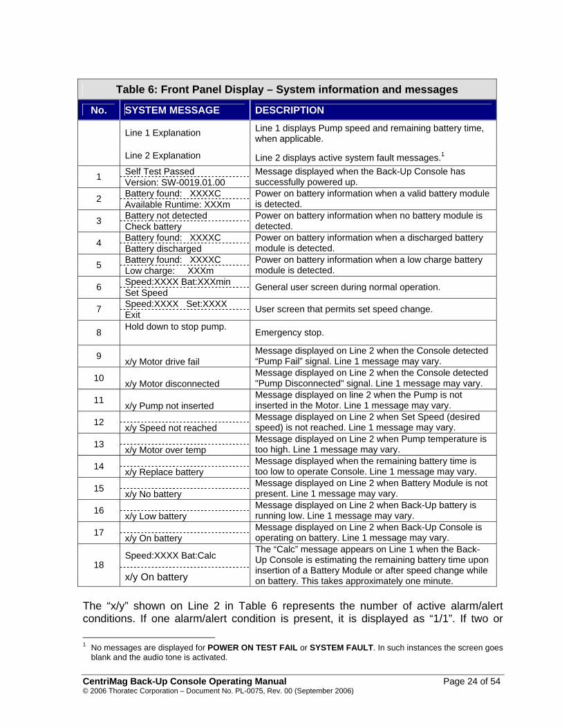
Table 6: Front Panel Display – System information and messages
No. SYSTEM MESSAGE DESCRIPTION
Line 1 Explanation
Line 2 Explanation
Line 1 displays Pump speed and remaining battery time, when applicable. Line 2 displays active system fault messages.1
Self Test Passed 1 Version: SW-0019.01.00 Message displayed when the Back-Up Console has successfully powered up.
Battery found: XXXXC 2 Available Runtime: XXXm Power on battery information when a valid battery module is detected.
Battery not detected 3 Check battery Power on battery information when no battery module is detected.
Battery found: XXXXC 4 Battery discharged Power on battery information when a discharged battery module is detected.
Battery found: XXXXC 5 Low charge: XXXm Power on battery information when a low charge battery module is detected.
Speed:XXXX Bat:XXXmin 6 Set Speed General user screen during normal operation.
Speed:XXXX Set:XXXX 7 Exit User screen that permits set speed change.
Hold down to stop pump. 8
Emergency stop.
9 x/y Motor drive fail Message displayed on Line 2 when the Console detected “Pump Fail” signal. Line 1 message may vary.
10 x/y Motor disconnected Message displayed on Line 2 when the Console detected "Pump Disconnected" signal. Line 1 message may vary.
11 x/y Pump not inserted Message displayed on line 2 when the Pump is not inserted in the Motor. Line 1 message may vary.
12 x/y Speed not reached Message displayed on Line 2 when Set Speed (desired speed) is not reached. Line 1 message may vary.
13 x/y Motor over temp Message displayed on Line 2 when Pump temperature is too high. Line 1 message may vary.
14 x/y Replace battery Message displayed when the remaining battery time is too low to operate Console. Line 1 message may vary.
15 x/y No battery Message displayed on Line 2 when Battery Module is not present. Line 1 message may vary.
16 x/y Low battery Message displayed on Line 2 when Back-Up battery is running low. Line 1 message may vary.
17 x/y On battery Message displayed on Line 2 when Back-Up Console is operating on battery. Line 1 message may vary.
Speed:XXXX Bat:Calc 18
x/y On battery
The “Calc” message appears on Line 1 when the Back-Up Console is estimating the remaining battery time upon insertion of a Battery Module or after speed change while on battery. This takes approximately one minute.
The “x/y” shown on Line 2 in Table 6 represents the number of active alarm/alert conditions. If one alarm/alert condition is present, it is displayed as “1/1”. If two or 1 No messages are displayed for POWER ON TEST FAIL or SYSTEM FAULT. In such instances the screen goes
blank and the audio tone is activated.
CentriMag Back-Up Console Operating Manual Page 24 of 54 © 2006 Thoratec Corporation – Document No. PL-0075, Rev. 00 (September 2006)
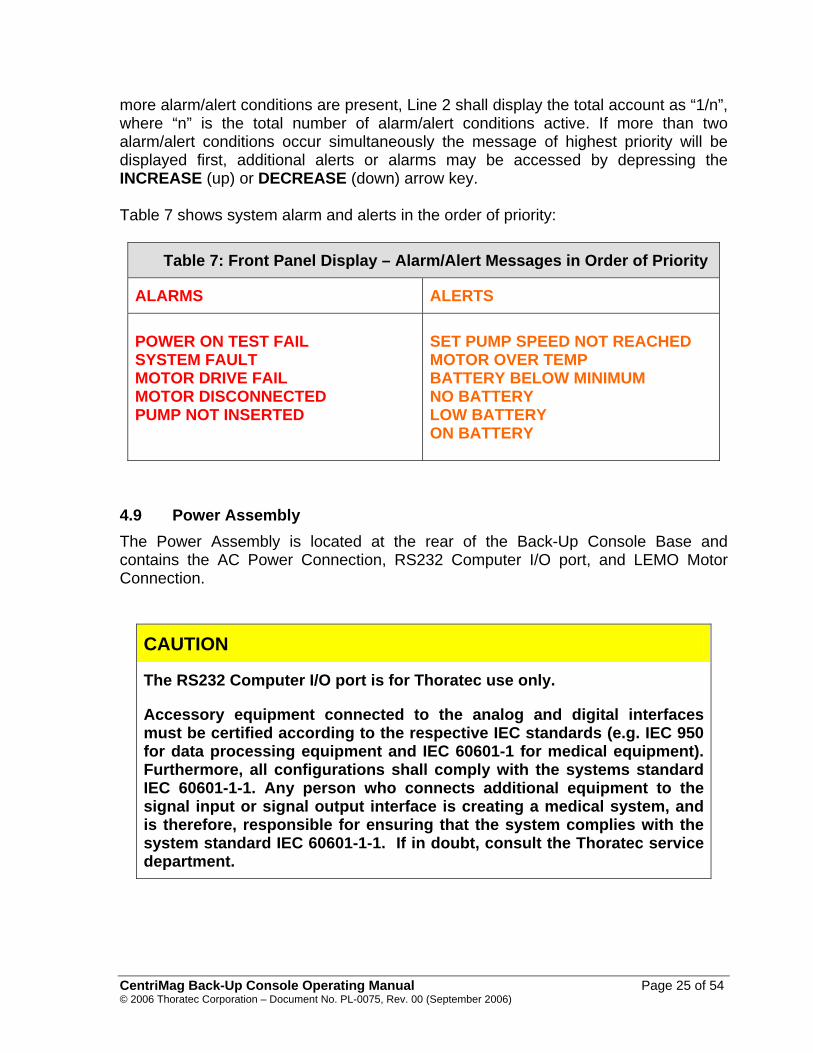
more alarm/alert conditions are present, Line 2 shall display the total account as “1/n”, where “n” is the total number of alarm/alert conditions active. If more than two alarm/alert conditions occur simultaneously the message of highest priority will be displayed first, additional alerts or alarms may be accessed by depressing the INCREASE (up) or DECREASE (down) arrow key. Table 7 shows system alarm and alerts in the order of priority:
Table 7: Front Panel Display – Alarm/Alert Messages in Order of Priority
ALARMS ALERTS POWER ON TEST FAIL SYSTEM FAULT MOTOR DRIVE FAIL MOTOR DISCONNECTED PUMP NOT INSERTED
SET PUMP SPEED NOT REACHED MOTOR OVER TEMP BATTERY BELOW MINIMUM NO BATTERY LOW BATTERY ON BATTERY
4.9 Power Assembly The Power Assembly is located at the rear of the Back-Up Console Base and contains the AC Power Connection, RS232 Computer I/O port, and LEMO Motor Connection.
CAUTION
The RS232 Computer I/O port is for Thoratec use only.
Accessory equipment connected to the analog and digital interfaces must be certified according to the respective IEC standards (e.g. IEC 950 for data processing equipment and IEC 60601-1 for medical equipment). Furthermore, all configurations shall comply with the systems standard IEC 60601-1-1. Any person who connects additional equipment to the signal input or signal output interface is creating a medical system, and is therefore, responsible for ensuring that the system complies with the system standard IEC 60601-1-1. If in doubt, consult the Thoratec service department.
CentriMag Back-Up Console Operating Manual Page 25 of 54 © 2006 Thoratec Corporation – Document No. PL-0075, Rev. 00 (September 2006)
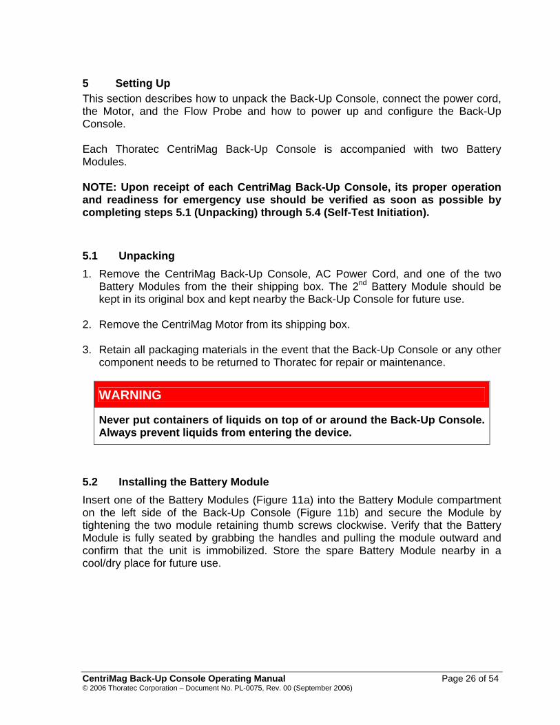
5 Setting Up This section describes how to unpack the Back-Up Console, connect the power cord, the Motor, and the Flow Probe and how to power up and configure the Back-Up Console. Each Thoratec CentriMag Back-Up Console is accompanied with two Battery Modules. NOTE: Upon receipt of each CentriMag Back-Up Console, its proper operation and readiness for emergency use should be verified as soon as possible by completing steps 5.1 (Unpacking) through 5.4 (Self-Test Initiation). 5.1 Unpacking 1. Remove the CentriMag Back-Up Console, AC Power Cord, and one of the two
Battery Modules from the their shipping box. The 2nd Battery Module should be kept in its original box and kept nearby the Back-Up Console for future use.
2. Remove the CentriMag Motor from its shipping box. 3. Retain all packaging materials in the event that the Back-Up Console or any other
component needs to be returned to Thoratec for repair or maintenance.
WARNING
Never put containers of liquids on top of or around the Back-Up Console. Always prevent liquids from entering the device.
5.2 Installing the Battery Module Insert one of the Battery Modules (Figure 11a) into the Battery Module compartment on the left side of the Back-Up Console (Figure 11b) and secure the Module by tightening the two module retaining thumb screws clockwise. Verify that the Battery Module is fully seated by grabbing the handles and pulling the module outward and confirm that the unit is immobilized. Store the spare Battery Module nearby in a cool/dry place for future use.
CentriMag Back-Up Console Operating Manual Page 26 of 54 © 2006 Thoratec Corporation – Document No. PL-0075, Rev. 00 (September 2006)

Figure 11a: CentriMag Battery Module
Figure 11b: CentriMag Back-Up Console Battery Module Compartment
Figure 11c: Battery Module Fully Inserted into the Compartment
Figure 11: Inserting Battery Module into the Battery Compartment
CentriMag Back-Up Console Operating Manual Page 27 of 54 © 2006 Thoratec Corporation – Document No. PL-0075, Rev. 00 (September 2006)

5.3 Powering Up 1. Insert the Power Cord into the AC Power Connection and flip and press the
connector latching mechanism over base of the power connector in order to fully secure the power cord to the Back-Up Console.
2. Insert the cord into the AC wall outlet. 3. Insert the LEMO connector on the Motor cable into the Motor Connection on the
rear of the Back-Up Console. 4. Turn ON the power to the Back-Up Console (the power switch located on the rear
panel of the Back-Up Console). 5. Check the Power Status on the Back-Up Console Display to verify that the green
AC power ON indicator is illuminated. The Back-Up Console should be connected to AC power whenever possible to preserve the life of the replaceable battery since the battery is not rechargeable.
6. Unplug the Back-Up Console from AC power. Verify that the Back-Up Console
continues to work and the ON BATTERY message is displayed followed by an audio indication. Press ALARM ACKNOWLEDGE and reconnect Back-Up Console to AC power.
WARNING
The Back-Up Console battery is not rechargeable, and will deplete its charge if the Back-Up Console is not operated with AC power. Always check the remaining battery time available upon powering-up the Back-Up Console.
5.4 Self-Test Initiation When the power is turned ON an automatic self-test sequence will immediately activate. All operating parameters will be verified. At the end of the self-test, the two enunciators in the Back-Up Console are cycled ON and OFF four times. Operator attention is required when the audio enunciators are tested to count the number of audio tones heard to verify that both enunciators are functioning. Only three audio tones will be heard if one of the enunciators has failed to activate. If both enunciators are functioning properly, but the Console has failed self-test, a subsequent audio tone will be heard accompanied by a blank Console display to declare self-test failure. The self-test fail audio tone cannot be silenced unless the unit is shut-down.
CentriMag Back-Up Console Operating Manual Page 28 of 54 © 2006 Thoratec Corporation – Document No. PL-0075, Rev. 00 (September 2006)

WARNING
If the Back-Up Console fails self test, immediately turn OFF the Back-Up Console, and attempt to re-boot. If Back-Up Console does not boot correctly, replace with another Console.
When the power-up self-test has completed successfully, the INITIALIZATION COMPLETE message along with the software version number (X.XX) will flash for approximately 10 seconds on the Back-Up Console display. This verifies proper Control Unit operation. Once 10 seconds have elapsed, the next screen becomes available. Pressing the ALARM ACKNOWLEDGE button within the 10-second window will terminate the INITALIZATION COMPLETE message. The Back-Up Console will display the next screen in which one of the four battery-status message groups listed in Table 8 will appear. Alarm/alert monitoring is active. SET SPEED will then be displayed indicating the Back-Up Console is ready for use.
Table 8: Possible Battery Status Messages after Completion of Self-Test Battery Status
Message Group Description Anticipated Operator Response
“Battery found: StdC” “Available Runtime: 000m”
"Battery found: StdC", where StdC is short for the Standard-Capacity Battery. "Available Runtime: 000m", where 000 is the actual battery run time remaining base on the nominal load.
None. The message disappears after 10 seconds or immediately if the ALARM ACKNOWLEDGE button is pressed.
“Battery not detected” “Check battery”
Battery Module not inserted or not seated properly.
Requires operator acknowledgment by pressing the ALARM ACKNOWLEDGE button. Insert Battery Module or check for proper seating.
“Battery found: StdC” “Battery discharged”
"Battery found: StdC", where StdC is short for the Standard-Capacity Battery. "Battery discharged” is indicated when less than 10 minutes of battery runtime, based on the
Requires operator acknowledgment by pressing the ALARM ACKNOWLEDGE button. Return the unit to AC power immediately or replace Battery Module,
CentriMag Back-Up Console Operating Manual Page 29 of 54 © 2006 Thoratec Corporation – Document No. PL-0075, Rev. 00 (September 2006)

Table 8: Possible Battery Status Messages after Completion of Self-Test Battery Status
Message Group Description Anticipated Operator Response
nominal load, is remaining.
as described in Section 6.7.
“Battery found: StdC” “Low charge: 000m”
"Battery found: StdC", where StdC is short for the Standard-Capacity Battery. "Low Charge: 030m" or “Low Charge: 020m”, is indicated when less than 30 ± 5 minutes of battery run time is remaining based on the nominal load.
Requires operator acknowledgment by pressing the ALARM ACKNOWLEDGE button. Return the unit to AC power within 30 minutes or replace Battery Module, as described in Section 6.7.
5.5 Language Selection The Back-Up Console’s digital display can present information in six languages: English, German, French, Italian, Dutch and Spanish. Language selection must only be done by trained service technicians.
5.6 Blood Pump Set-up Refer to CentriMag Blood Pump Instructions for Use for proper setup and operation of the CentriMag Blood Pump.
WARNING
Always fully unscrew the Blood Pump retaining screw before inserting the Blood Pump in the Motor. Failure to do so may inhibit the ability to fully insert the Blood Pump, resulting in loss of function and a “MOTOR FAILURE” alarm. Should this condition occur, remove the Blood Pump, unscrew the retaining screw, reinsert the Pump, rotate the Blood Pump counter-clockwise into position, then tighten the retaining screw to secure the Pump into a locked position and begin pumping.
CentriMag Back-Up Console Operating Manual Page 30 of 54 © 2006 Thoratec Corporation – Document No. PL-0075, Rev. 00 (September 2006)

6 Operating This section describes the operation of the Back-Up Console including starting and stopping the Blood Pump and adjusting the Blood Pump speed. This section also contains information on the system parameters, alarms and battery operation for patient transport. NOTE: If there is any doubt regarding the integrity of the protective earth connection of the AC circuit or power cord, the unit should be operated on battery power until safe AC power can be applied to the unit. 6.1 Operation of the Blood Pump
WARNING
Increase Blood Pump RPM in small increments to minimize the risk of causing suction and cavitation.
WARNING
The CentriMag Back-Up Console does not incorporate flow and pressure measurement capability. Because flow and in some instances pressure measurements are critical for determining appropriate support levels, flow and pressure levels are to be monitored when the CentriMag Back-Up console is in use. Monitor the flow by employing an independent ultrasonic flow meter and probe comparable to the Transonic Flow Meter and Transonic XL Series Flow Probe. Pressure may be monitored using a pressure transducer with properties comparable to the Becton Dickenson Pressure Transducer DTX-Plus Series which is used with the CentriMag Primary Console. The CentriMag Back-Up Console should be exchanged for a replacement Primary Console as soon as possible.
WARNING
The CentriMag Blood Pump may stop and display “Motor Fail” during use of a Valley Lab Model SSE2L electrocautery device. Should this occur, clamp pump outflow line, switch to bipolar mode on the electrocautery device then reboot the CentriMag Console and reinitiate support. Switch to a back-up system if the device fails to operate following rebooting. Once the system is operational, unclamp the outlet tubing and resume support.
CentriMag Back-Up Console Operating Manual Page 31 of 54 © 2006 Thoratec Corporation – Document No. PL-0075, Rev. 00 (September 2006)

6.1.1 Starting the Blood Pump To start the Blood Pump, perform the following steps: 1. Place the Blood Pump into the Motor receptacle and secure in place per the
Instructions for Use supplied with the Blood Pump. 2. Start the Blood Pump by first depressing the SET SPEED keypad. SET PUMP
SPEED = 0000 RPM will be displayed. Depress the INCREASE keypad until the RPM and flow rate is at the desired level.
The RPM will be displayed on the Back-Up Console. 6.1.2 Adjusting Blood Pump Speed Blood Pump speed can be adjusted by first depressing the SET SPEED keypad and then depressing the INCREASE or DECREASE keypads. The available speed range is between 500 and 5500 RPM. Flow at a given RPM is dependent upon the patient’s hemodynamic status and the resistance of the extracorporeal blood circuit.
6.1.3 Manually Stopping the Blood Pump Depressing and holding the STOP keypad for two seconds manually stops the Blood Pump if the Blood Pump is running. While depressing the STOP keypad the message TO STOP PUMP HOLD DOWN STOP KEY will be displayed. Alternatively, in an emergency, the Blood Pump may be stopped by switching the AC Power Switch to OFF and clamping the Blood Pump outlet tubing with a smooth jawed tubing clamp to prevent retrograde flow.
WARNING
Only switch Main Power Switch OFF in an emergency. Make certain to switch Main Power Switch to ON when the problem is resolved.
6.1.4 Restarting the Blood Pump If the Blood Pump has been stopped, either manually or from an alarm condition, the user should follow the Blood Pump restart sequence described below.
CentriMag Back-Up Console Operating Manual Page 32 of 54 © 2006 Thoratec Corporation – Document No. PL-0075, Rev. 00 (September 2006)
WARNING
DO NOT attempt to restart the Blood Pump after it has been stopped for more than 5 minutes without adequate anticoagulation, as the risk of thromboembolism is increased after blood has remained stagnant in the Blood Pump. In addition, do not restart the Blood Pump if it has stopped due to Motor overheating.
WARNING
A Blood Pump stoppage will create a reverse flow shunt, as well as limit the body’s ability to maintain adequate arterial pressure. Clamping the Blood Pump outlet tubing is necessary to prevent a low flow or low pressure incident in a Pump-off scenario. The tubing clamp must be removed before returning to normal pumping activity.
WARNING
Increase Blood Pump RPM in small increments to minimize the risk of causing suction and cavitation.
To restart the Blood Pump, perform the following steps: 1. Insure that the Blood Pump is securely located in the Motor per the Instructions for
Use supplied with the Blood Pump. 2. Insure that any alarm condition has been corrected. 3. Start the Blood Pump by first depressing the SET SPEED keypad and then
depressing the INCREASE keypad until the RPM is at the desired level. 4. Remove the tubing clamp from the circuit.
The RPM will be displayed on the Back-Up Console. 6.2 Special Alarm Stop If the Blood Pump was stopped because of one of the alarm conditions listed in Table 9, replace the Back-Up Console and Motor with another Console and Motor. If another Console is not available attempt to correct the alarm condition, turn the Back-Up Console MAIN POWER SWITCH to OFF and then back to ON. Once SET SPEED is displayed, depress the SET SPEED keypad and then depress the INCREASE keypad until the flow rate is at the desired level.
CentriMag Back-Up Console Operating Manual Page 33 of 54 © 2006 Thoratec Corporation – Document No. PL-0075, Rev. 00 (September 2006)

Table 9: Alarm Conditions Requiring Powering Off Before Restarting
POWER ON TEST FAIL
SYSTEM FAULT MOTOR DRIVE FAIL
If the Blood Pump does not restart, turn the Back-Up Console OFF and disconnect it from AC power and use another Console.
WARNING
It is intended that systemic anticoagulation be utilized while the CentriMag System is in use. Anticoagulation levels should be determined by the physician based on risks and benefits to the patient.
6.3 Alarms and Alerts The Thoratec CentriMag Back-Up Console alarm strategy is based on the following philosophy. Audio and visual advisories are divided into two groups, System Alerts and System Alarms, to warn the operator of conditions that may interrupt patient support or damage the Blood Pump, Motor Drive Unit or Back-Up Console. A normal operating condition is free of any alerts or alarms and is classified as a green state of operation. Alert Advisories activate when the system is about to, or has entered, an unsafe but resolvable operating state (yellow state). Alarm Advisories activate when the system is about to, or has entered, an unsafe state of operation which may be hazardous to the patient or operator (red state). Table 10 below illustrates the fundamental strategy:
Table 10: Thoratec Back-Up Console Alarm/Alert Advisory Strategy
Operating State
Advisory Level Anticipated Operator Response
Green
Yellow
Red
None
Alert
Alarm
None
Resolve Fault Condition
Resolve Alarm Condition
or Switch to another Console/Motor
If an alarm or alert condition occurs, the audible advisory sounds along with a visual
CentriMag Back-Up Console Operating Manual Page 34 of 54 © 2006 Thoratec Corporation – Document No. PL-0075, Rev. 00 (September 2006)
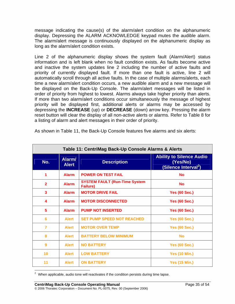
message indicating the cause(s) of the alarm/alert condition on the alphanumeric display. Depressing the ALARM ACKNOWLEDGE keypad mutes the audible alarm. The alarm/alert message is continuously displayed on the alphanumeric display as long as the alarm/alert condition exists. Line 2 of the alphanumeric display shows the system fault (Alarm/Alert) status information and is left blank when no fault condition exists. As faults become active and inactive the system updates line 2 including the number of active faults and priority of currently displayed fault. If more than one fault is active, line 2 will automatically scroll through all active faults. In the case of multiple alarms/alerts, each time a new alarm/alert condition occurs, a new audible alarm and a new message will be displayed on the Back-Up Console. The alarm/alert messages will be listed in order of priority from highest to lowest. Alarms always take higher priority than alerts. If more than two alarm/alert conditions occur simultaneously the message of highest priority will be displayed first, additional alerts or alarms may be accessed by depressing the INCREASE (up) or DECREASE (down) arrow key. Pressing the alarm reset button will clear the display of all non-active alerts or alarms. Refer to Table 8 for a listing of alarm and alert messages in their order of priority. As shown in Table 11, the Back-Up Console features five alarms and six alerts:
Table 11: CentriMag Back-Up Console Alarms & Alerts
No. Alarm/ Alert Description
Ability to Silence Audio (Yes/No)
(Silence Interval2) 1 Alarm POWER ON TEST FAIL No
2 Alarm SYSTEM FAULT (Run-Time System Failure) No
3 Alarm MOTOR DRIVE FAIL Yes (60 Sec.)
4 Alarm MOTOR DISCONNECTED Yes (60 Sec.)
5 Alarm PUMP NOT INSERTED Yes (60 Sec.)
6 Alert SET PUMP SPEED NOT REACHED Yes (60 Sec.)
7 Alert MOTOR OVER TEMP Yes (60 Sec.)
8 Alert BATTERY BELOW MINIMUM No
9 Alert NO BATTERY Yes (60 Sec.)
10 Alert LOW BATTERY Yes (10 Min.)
11 Alert ON BATTERY Yes (15 Min.)
2 When applicable, audio tone will reactivates if the condition persists during time lapse.
CentriMag Back-Up Console Operating Manual Page 35 of 54 © 2006 Thoratec Corporation – Document No. PL-0075, Rev. 00 (September 2006)
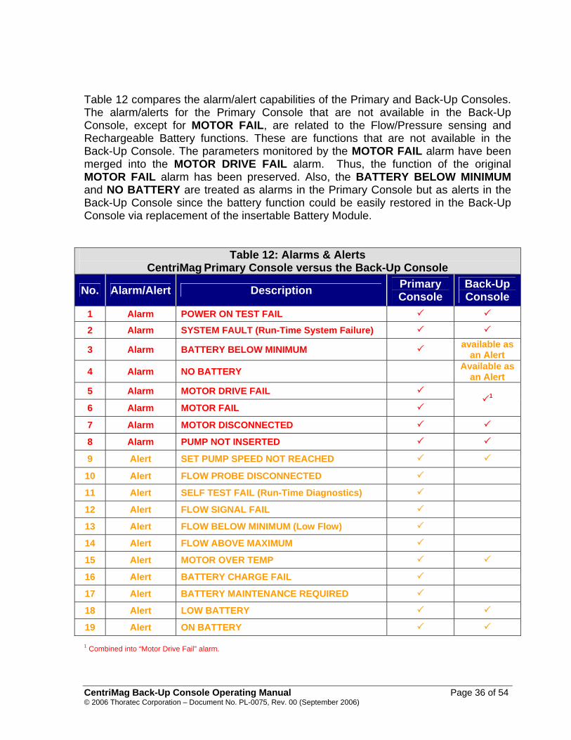
Table 12 compares the alarm/alert capabilities of the Primary and Back-Up Consoles. The alarm/alerts for the Primary Console that are not available in the Back-Up Console, except for MOTOR FAIL, are related to the Flow/Pressure sensing and Rechargeable Battery functions. These are functions that are not available in the Back-Up Console. The parameters monitored by the MOTOR FAIL alarm have been merged into the MOTOR DRIVE FAIL alarm. Thus, the function of the original MOTOR FAIL alarm has been preserved. Also, the BATTERY BELOW MINIMUM and NO BATTERY are treated as alarms in the Primary Console but as alerts in the Back-Up Console since the battery function could be easily restored in the Back-Up Console via replacement of the insertable Battery Module.
Table 12: Alarms & Alerts CentriMag Primary Console versus the Back-Up Console
No. Alarm/Alert Description Primary Console
Back-Up Console
1 Alarm POWER ON TEST FAIL 2 Alarm SYSTEM FAULT (Run-Time System Failure)
3 Alarm BATTERY BELOW MINIMUM available as an Alert
4 Alarm NO BATTERY Available as an Alert
5 Alarm MOTOR DRIVE FAIL 6 Alarm MOTOR FAIL
1
7 Alarm MOTOR DISCONNECTED 8 Alarm PUMP NOT INSERTED 9 Alert SET PUMP SPEED NOT REACHED
10 Alert FLOW PROBE DISCONNECTED
11 Alert SELF TEST FAIL (Run-Time Diagnostics)
12 Alert FLOW SIGNAL FAIL
13 Alert FLOW BELOW MINIMUM (Low Flow)
14 Alert FLOW ABOVE MAXIMUM
15 Alert MOTOR OVER TEMP
16 Alert BATTERY CHARGE FAIL
17 Alert BATTERY MAINTENANCE REQUIRED
18 Alert LOW BATTERY
19 Alert ON BATTERY
1 Combined into “Motor Drive Fail” alarm.
CentriMag Back-Up Console Operating Manual Page 36 of 54 © 2006 Thoratec Corporation – Document No. PL-0075, Rev. 00 (September 2006)

A complete list of all Alarms and Alerts may also be found in Appendix 1. This list includes a description of each advisory, the system response and the anticipated response of the operator. 6.4 Alarms In the event of an Alarm condition (see Appendix I for alarm condition listing), the Back-Up Console stops the Blood Pump. The Back-Up Console allows the user to acknowledge the Alarm, which silences the audio alarm tone, but will not remove the visual message and will not allow pumping to continue until the alarm condition no longer exists. If the alarm condition remains for more than 60 seconds after the alarm has been acknowledged, the audio alarm tone reactivates and continues until acknowledged. Run time diagnostic messages/alarms only need to be acknowledged once and will not reactivate until the next occurrence after the alarm silence button has been pressed. The recommended action by the operator during an Alarm Condition is to rapidly assess and respond to the cause of the alarm condition. If equipment change is necessary clamp the Blood Pump outlet tubing before moving to Back-Up equipment to prevent retrograde flow. Always unclamp the tubing prior to resumption of pumping.
WARNING
Alarms are associated with conditions that require the Blood Pump to stop. To prevent retrograde flow through the Blood Pump during an alarm condition the outlet tubing must be clamped.
WARNING
DO NOT attempt to restart the Blood Pump after it has been stopped for more than 5 minutes without adequate anticoagulation, as the risk of thromboembolism is increased after blood has remained stagnant in the Blood Pump.
WARNING
DO NOT restart the Blood Pump if it has stopped due to Motor overheating. Immediately clamp the outlet tubing, confirm overheating has occurred by checking the temperature of the Motor, and take emergency steps to either terminate support and remove all circuit components or replace the entire circuit (tubing, Blood Pump, Motor and Console).
CentriMag Back-Up Console Operating Manual Page 37 of 54 © 2006 Thoratec Corporation – Document No. PL-0075, Rev. 00 (September 2006)
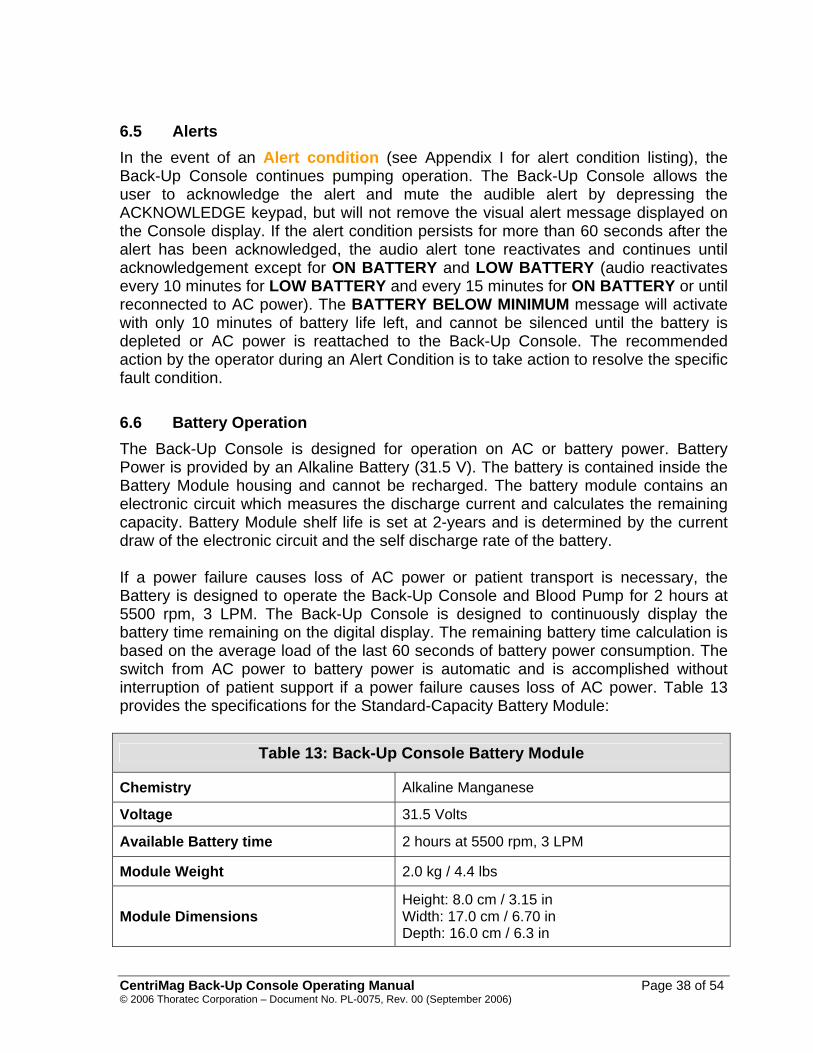
6.5 Alerts In the event of an Alert condition (see Appendix I for alert condition listing), the Back-Up Console continues pumping operation. The Back-Up Console allows the user to acknowledge the alert and mute the audible alert by depressing the ACKNOWLEDGE keypad, but will not remove the visual alert message displayed on the Console display. If the alert condition persists for more than 60 seconds after the alert has been acknowledged, the audio alert tone reactivates and continues until acknowledgement except for ON BATTERY and LOW BATTERY (audio reactivates every 10 minutes for LOW BATTERY and every 15 minutes for ON BATTERY or until reconnected to AC power). The BATTERY BELOW MINIMUM message will activate with only 10 minutes of battery life left, and cannot be silenced until the battery is depleted or AC power is reattached to the Back-Up Console. The recommended action by the operator during an Alert Condition is to take action to resolve the specific fault condition. 6.6 Battery Operation The Back-Up Console is designed for operation on AC or battery power. Battery Power is provided by an Alkaline Battery (31.5 V). The battery is contained inside the Battery Module housing and cannot be recharged. The battery module contains an electronic circuit which measures the discharge current and calculates the remaining capacity. Battery Module shelf life is set at 2-years and is determined by the current draw of the electronic circuit and the self discharge rate of the battery. If a power failure causes loss of AC power or patient transport is necessary, the Battery is designed to operate the Back-Up Console and Blood Pump for 2 hours at 5500 rpm, 3 LPM. The Back-Up Console is designed to continuously display the battery time remaining on the digital display. The remaining battery time calculation is based on the average load of the last 60 seconds of battery power consumption. The switch from AC power to battery power is automatic and is accomplished without interruption of patient support if a power failure causes loss of AC power. Table 13 provides the specifications for the Standard-Capacity Battery Module:
Table 13: Back-Up Console Battery Module
Chemistry Alkaline Manganese
Voltage 31.5 Volts
Available Battery time 2 hours at 5500 rpm, 3 LPM
Module Weight 2.0 kg / 4.4 lbs
Module Dimensions Height: 8.0 cm / 3.15 in Width: 17.0 cm / 6.70 in Depth: 16.0 cm / 6.3 in
CentriMag Back-Up Console Operating Manual Page 38 of 54 © 2006 Thoratec Corporation – Document No. PL-0075, Rev. 00 (September 2006)

Table 13: Back-Up Console Battery Module
Operating Temp Range -20ºC to 54ºC -4ºF to 130ºF
Storage Temp Range -30ºC to 35ºC -22ºF to 95ºF
Shelf Life 24 Month
Rechargeable No, Non-rechargeable Handling & Transportation Requirements* No special requirements
Disposal* Return to Thoratec * Depleted Battery Modules should be disposed of in compliance with local, state and federal requirements or
returned back to Thoratec for proper disposal. Figure 12 provides available battery time at various pressures and Pump speeds when the system is operating on Battery power.
Figure 12: Battery Module’s expected battery remaining time is transposed over
the CentriMag Blood Pump Pressure/Flow Curve
CentriMag Back-Up Console Operating Manual Page 39 of 54 © 2006 Thoratec Corporation – Document No. PL-0075, Rev. 00 (September 2006)
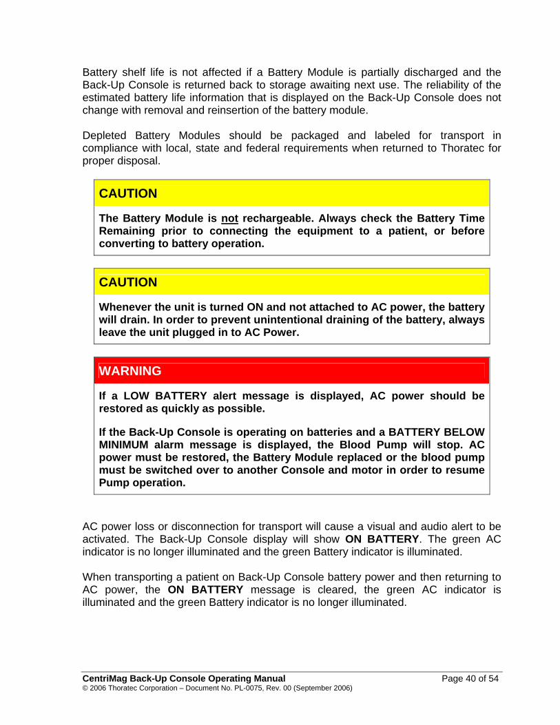
Battery shelf life is not affected if a Battery Module is partially discharged and the Back-Up Console is returned back to storage awaiting next use. The reliability of the estimated battery life information that is displayed on the Back-Up Console does not change with removal and reinsertion of the battery module. Depleted Battery Modules should be packaged and labeled for transport in compliance with local, state and federal requirements when returned to Thoratec for proper disposal.
CAUTION
The Battery Module is not rechargeable. Always check the Battery Time Remaining prior to connecting the equipment to a patient, or before converting to battery operation.
CAUTION
Whenever the unit is turned ON and not attached to AC power, the battery will drain. In order to prevent unintentional draining of the battery, always leave the unit plugged in to AC Power.
WARNING
If a LOW BATTERY alert message is displayed, AC power should be restored as quickly as possible.
If the Back-Up Console is operating on batteries and a BATTERY BELOW MINIMUM alarm message is displayed, the Blood Pump will stop. AC power must be restored, the Battery Module replaced or the blood pump must be switched over to another Console and motor in order to resume Pump operation.
AC power loss or disconnection for transport will cause a visual and audio alert to be activated. The Back-Up Console display will show ON BATTERY. The green AC indicator is no longer illuminated and the green Battery indicator is illuminated. When transporting a patient on Back-Up Console battery power and then returning to AC power, the ON BATTERY message is cleared, the green AC indicator is illuminated and the green Battery indicator is no longer illuminated.
CentriMag Back-Up Console Operating Manual Page 40 of 54 © 2006 Thoratec Corporation – Document No. PL-0075, Rev. 00 (September 2006)

6.6.1 Interpreting the “Battery Time Remaining” Information The Back-Up Console is designed to operate on both AC Power and on Batteries. The estimated time available to operate on a Battery Module is always displayed whether operating on AC or Battery Power. The following guidance is offered for how to understand and interpret the displayed information. 6.6.1.1 Operating on AC Power When the Back-Up Console is initially turned ON and is on Mains Power, an estimate of the remaining battery time is automatically displayed. The estimated time is representative of how long the system is capable of running on batteries under nominal operating conditions (5.5 lpm at 3,500 RPM). The displayed time will range from 10 to 299 minutes. The estimate will not vary while operating on Mains Power; it is only intended to serve as a means to guide the user regarding the typical length of battery time available should the system be operated under nominal conditions. If the system has been operating on batteries and is switched over to Mains power, the displayed time reflects the battery remaining time based on the last operating condition while the system was operated on batteries. This estimate is intended to provide a more precise prediction of battery remaining time relative to the most recent operating condition associated with supporting the patient. 6.6.1.2 Operating ON Battery Power If the Motor speed is adjusted by the user when operating on batteries, sensors within the system detect the new operating condition via a change in Motor current which leads to an update of the estimated time remaining on batteries. When the speed is altered, the display informs the user that the unit is CALCULATING (“Calc”) the change in Battery Time Remaining. The calculation requires approximately one minute from the time the speed has been changed. Similarly, the system automatically detects a change in current when the physiologic conditions change, such as following a change in pressure, leading to an update in time remaining on batteries. This estimate is based on averaged data taken over 60 second intervals. As a result, the estimated time remaining on batteries will fluctuate dependent on the speed and change in physiologic conditions. Significant changes in speed will have a marked impact on remaining time on batteries. The rationale for informing the user that the system is calculating the remaining battery time is to urge the user to reexamine the displayed time after implementing a change and not to rely on the previous estimates.
CentriMag Back-Up Console Operating Manual Page 41 of 54 © 2006 Thoratec Corporation – Document No. PL-0075, Rev. 00 (September 2006)

CAUTION
When operating ON Batteries, always reexamine the estimated Battery Time Remaining after changing RPM or operating conditions. The recalculation of Battery Time Remaining takes approximately 60 seconds. Listen for Battery Alerts and Alarms and respond per the instructions provided in Appendix I.
CAUTION
Always operate the system at the lowest acceptable clinical flows when operating ON Batteries to conserve remaining Battery time. Whenever possible, keep flows above 2.0 lpm and administer appropriate anticoagulation.
CAUTION
Confirm that the system is operating on AC or Battery Power by viewing the lit LED for the appropriate power source on the indicator to the right of the display.
6.7 Battery Module Replacement Remove battery module from the left side of the Back-Up console by loosening the two module retaining screws. Replace the old Battery Module with a fresh replacement obtained from Thoratec. Fully seat the replacement Module into the compartment and rotate the retaining screws clockwise to secure the module in place (see Section 5.2). Verify that the Battery Module is fully seated by grabbing and pulling towards you using the Battery Module’s handles.
CAUTION
Do not attempt to replace the Battery Module when the Back-Up Console is powered with battery power. The Battery Module may only be replaced when the Back-Up Console is powered with AC power or when Console is OFF. If AC power is not available the Back-Up Console must be turned OFF, the circuit clamped to prevent retrograde flow, the battery replaced, the Back-Up Console turned back on, and flow resumed.
CentriMag Back-Up Console Operating Manual Page 42 of 54 © 2006 Thoratec Corporation – Document No. PL-0075, Rev. 00 (September 2006)

CAUTION
Always have a spare Battery Module readily available and in the vicinity of the Back-Up Console.
CentriMag Back-Up Console Operating Manual Page 43 of 54 © 2006 Thoratec Corporation – Document No. PL-0075, Rev. 00 (September 2006)

7 Maintenance Instructions for how to change the fuses and maintain the Back-Up Console are provided below. 7.1 Changing Fuses
CAUTION
The Back-Up Console must be unplugged from AC power source while replacing fuses.
Main system fuses are located just above the receptacle for the AC power cord on the rear panel of the Back-Up Console. To change a fuse, follow the steps below: 1. Unplug the Back-Up Console. 2. Locate the Fuse Cartridge Release Tab and gently press up on the Tab with a
small flathead screwdriver inserted into the Release Tab Slot. The Fuse Cartridge will partially eject.
3. Gently remove the Fuse. The fuses are secured in the end of the cartridge. 4. Remove a blown fuse by pulling the fuse out from the cartridge, and replace it only
with an identical T3.15A 250V fuse (3.15 Amp, 5 mm x 20 mm, time delay fuse). (Consult Thoratec for recommended replacements.)
5. After blown fuses have been replaced, secure the Fuse Cartridge in place by
pushing the cartridge into its receptacle until the Release Tab clicks into place. 6. Reconnect the Back-Up Console to AC power. 7.2 Maintenance Following Each Patient Use
WARNING
DO NOT spray bactericidal solution directly on the Back-Up Console. Spray bactericidal or cleaning solutions on a cloth, and then wipe surfaces with the cloth.
CentriMag Back-Up Console Operating Manual Page 44 of 54 © 2006 Thoratec Corporation – Document No. PL-0075, Rev. 00 (September 2006)

Immediately after using the Back-Up Console for a patient procedure, the Back-Up Console should be thoroughly cleaned using the following procedure: 1. Disconnect AC power before cleaning the exterior of the Back-Up Console. 2. Clean exterior of the Back-Up Console with bactericidal solution, by spraying the
solution on a cloth and wiping off the unit. 3. Reconnect AC power when cleaning is completed.
WARNING
The Back-Up Console should not be covered with plastic or insulating material during use or powered storage as it may over heat.
7.3 Recommended Preventive Maintenance The services listed in Table 14 are to be performed by qualified personnel trained by Thoratec. These maintenance processes are not to be performed when the system is in clinical use.
Table 14: Back-Up Console Maintenance Schedule
Required Action After Each Use
Every 6 Months
Every 12 Months
Verify the status of the non-rechargeable Battery Module. Replace the Battery Module as necessary.
X X X
Verify the general condition of the Back-Up Console. If any damage is present return the Back-Up Console to Thoratec for service.
X X X
Verify that all labels on the device are present and legible.
X X X
Verify that the leakage currents comply with the requirements of IEC 60601-1.
X
Verify that the ground resistance complies with the requirements of IEC 60601-1.
X
CentriMag Back-Up Console Operating Manual Page 45 of 54 © 2006 Thoratec Corporation – Document No. PL-0075, Rev. 00 (September 2006)

8 Emergency This section contains instructions for operation of the Blood Pump during external defibrillation, and under circumstances where there is a need to exchange the primary Back-Up Console or Motor with a Back-Up Console or Motor.
WARNING
A Blood Pump stoppage will create a reverse flow shunt, as well as limit the bodies’ ability to maintain adequate arterial pressure. If the Blood Pump is off, Clamping the Blood Pump outlet tubing is necessary to prevent a low flow or low pressure, or reverse flow condition. The tubing clamp must be removed before returning to normal pumping activity.
8.1 Switching to another Console and Motor
At all times a Back-Up (or alternate) Console and motor should be immediately available for use. If a patient is being support with a Back-Up console the alternate console can be another “Back-Up Console”. Should the Back-Up Console in use cease to function, it will be necessary to switch the Blood Pump from the Console and Motor in use to an alternate Back-Up console and motor. Switching to a Back-Up Console and Motor is performed in accordance with the steps shown in Figure 13. Whenever possible, switch all components (Console, Motor, and cables) simultaneously and then perform troubleshooting on the non-functioning system when it is no longer being used for patient support. If another alternate or Back-Up Console is available, but another Motor is not available then it will be necessary to switch Consoles without switching the Motor. This can be accomplished by shutting down the Back-Up Console, disconnecting the Motor’s round LEMO connector from the back of the Back-Up Console, connecting the LEMO connector to a replacement Console (either Primary or Back-Up), and then reestablishing pumping operation via the Console. Be sure to reset the operating condition to match the operating point prior to Back-Up Console exchange.
NOTE: To be available for emergency use the Back-Up Console must be with the Primary Console and plugged into AC power, with the main power switch on the Back-Up Console turned OFF. The remaining battery power must be periodically assessed by turning the main power switch ON, checking the status of the battery, and then turning the main power switch off. Operate the Back-Up Console as described in Section 6.
CentriMag Back-Up Console Operating Manual Page 46 of 54 © 2006 Thoratec Corporation – Document No. PL-0075, Rev. 00 (September 2006)

8.2 Switching to another Motor As shown in Figure 13, to replace the Motor, clamp the outlet tubing while lowering the RPM to zero prior to turning the Back-Up Console OFF. Unthread the Blood Pump retaining screw on the Motor by turning the screw counterclockwise several revolutions until the screw tip is clear of the locking groove on the Blood Pump. Rotate the Blood Pump body clockwise until the grooves in the Blood Pump match the Motor. Lift the Blood Pump from the receptacle. Place the Blood Pump in the Back-Up Motor receptacle (the Blood Pump will drop into place in one of 3 orientations). Rotate the Blood Pump counterclockwise until it stops, then thread the Blood Pump retaining screw to secure the Blood Pump in place by turning the screw clockwise until it stops. Power may now be re-established, and Pump operation should be returned to the last operating condition of the Blood Pump prior to Motor replacement. Be sure to reset options and alarms to match those selected before Motor replacement.
Figure 13: Emergency Switch to Backup System If the Blood Pump has been OFF for more than five minutes without adequate anticoagulation or if there has been a Motor overheating condition, it may be
CentriMag Back-Up Console Operating Manual Page 47 of 54 © 2006 Thoratec Corporation – Document No. PL-0075, Rev. 00 (September 2006)
necessary to replace the entire circuit (tubing, Blood Pump, Motor and Console). To do so, disconnect the Blood Pump and any affected tubing. Attach the Blood Pump per the standard procedure, prime and debubble. Operate the Back-Up Console as described in Section 6.
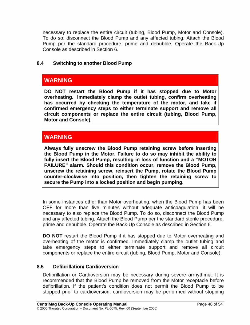
8.4 Switching to another Blood Pump
WARNING
DO NOT restart the Blood Pump if it has stopped due to Motor overheating. Immediately clamp the outlet tubing, confirm overheating has occurred by checking the temperature of the motor, and take if confirmed emergency steps to either terminate support and remove all circuit components or replace the entire circuit (tubing, Blood Pump, Motor and Console).
WARNING
Always fully unscrew the Blood Pump retaining screw before inserting the Blood Pump in the Motor. Failure to do so may inhibit the ability to fully insert the Blood Pump, resulting in loss of function and a “MOTOR FAILURE” alarm. Should this condition occur, remove the Blood Pump, unscrew the retaining screw, reinsert the Pump, rotate the Blood Pump counter-clockwise into position, then tighten the retaining screw to secure the Pump into a locked position and begin pumping.
In some instances other than Motor overheating, when the Blood Pump has been OFF for more than five minutes without adequate anticoagulation, it will be necessary to also replace the Blood Pump. To do so, disconnect the Blood Pump and any affected tubing. Attach the Blood Pump per the standard sterile procedure, prime and debubble. Operate the Back-Up Console as described in Section 6. DO NOT restart the Blood Pump if it has stopped due to Motor overheating and overheating of the motor is confirmed. Immediately clamp the outlet tubing and take emergency steps to either terminate support and remove all circuit components or replace the entire circuit (tubing, Blood Pump, Motor and Console).
8.5 Defibrillation/ Cardioversion
Defibrillation or Cardioversion may be necessary during severe arrhythmia. It is recommended that the Blood Pump be removed from the Motor receptacle before defibrillation. If the patient’s condition does not permit the Blood Pump to be stopped prior to cardioversion, cardioversion may be performed without stopping
CentriMag Back-Up Console Operating Manual Page 48 of 54 © 2006 Thoratec Corporation – Document No. PL-0075, Rev. 00 (September 2006)
the Blood Pump. Under this condition insure a backup system is available in the event of a primary system malfunction. In the event that the Blood Pump is to be removed from the Motor for Cardioversion, always stop the Blood Pump and clamp the outlet line of the circuit prior to removing it from the Motor. Return the Blood Pump to the Motor receptacle after defibrillation and insert per the instructions above. Unclamp the outlet line, and return to the desired operating condition after the Defibrillation or Cardioversion procedure has been completed.
WARNING
After defibrillation or cardioversion is performed, ensure that the Back-Up Console is working correctly.
CentriMag Back-Up Console Operating Manual Page 49 of 54 © 2006 Thoratec Corporation – Document No. PL-0075, Rev. 00 (September 2006)

9 Disposal of Equipment Depleted Battery Modules should be packaged and labeled for transport in compliance with local, state and federal requirements when returned to Thoratec for proper disposal. At the end of the Back-Up Console’s useful service life, all parts are to be sent back to Thoratec for proper disposal. Please contact Thoratec for any special return instructions.
CAUTION
Depleted Battery Modules should be packaged and labeled for transport in compliance with local, state and federal requirements when returned to Thoratec for proper disposal.
CentriMag Back-Up Console Operating Manual Page 50 of 54 © 2006 Thoratec Corporation – Document No. PL-0075, Rev. 00 (September 2006)
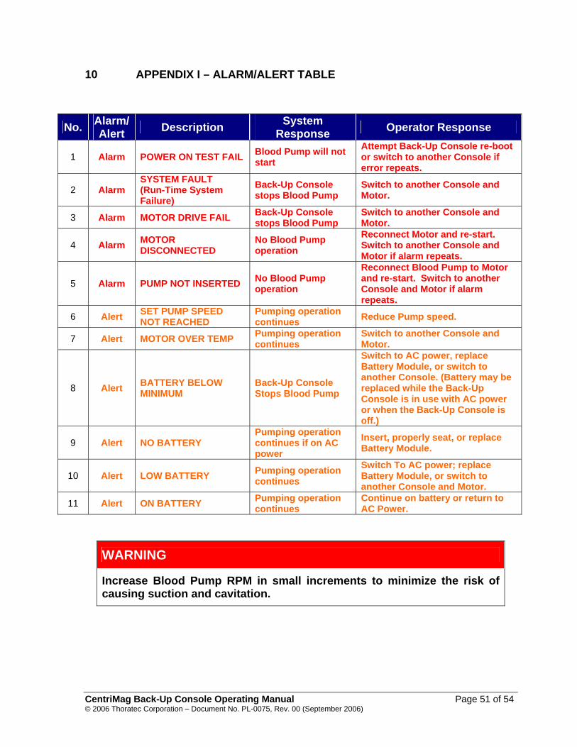
10 APPENDIX I – ALARM/ALERT TABLE
No. Alarm/ Alert Description System
Response Operator Response
1 Alarm POWER ON TEST FAIL Blood Pump will not start
Attempt Back-Up Console re-boot or switch to another Console if error repeats.
2 Alarm SYSTEM FAULT (Run-Time System Failure)
Back-Up Console stops Blood Pump
Switch to another Console and Motor.
3 Alarm MOTOR DRIVE FAIL Back-Up Console stops Blood Pump
Switch to another Console and Motor.
4 Alarm MOTOR DISCONNECTED
No Blood Pump operation
Reconnect Motor and re-start. Switch to another Console and Motor if alarm repeats.
5 Alarm PUMP NOT INSERTED No Blood Pump operation
Reconnect Blood Pump to Motor and re-start. Switch to another Console and Motor if alarm repeats.
6 Alert SET PUMP SPEED NOT REACHED
Pumping operation continues Reduce Pump speed.
7 Alert MOTOR OVER TEMP Pumping operation continues
Switch to another Console and Motor.
8 Alert BATTERY BELOW MINIMUM
Back-Up Console Stops Blood Pump
Switch to AC power, replace Battery Module, or switch to another Console. (Battery may be replaced while the Back-Up Console is in use with AC power or when the Back-Up Console is off.)
9 Alert NO BATTERY Pumping operation continues if on AC power
Insert, properly seat, or replace Battery Module.
10 Alert LOW BATTERY Pumping operation continues
Switch To AC power; replace Battery Module, or switch to another Console and Motor.
11 Alert ON BATTERY Pumping operation continues
Continue on battery or return to AC Power.
WARNING
Increase Blood Pump RPM in small increments to minimize the risk of causing suction and cavitation.
CentriMag Back-Up Console Operating Manual Page 51 of 54 © 2006 Thoratec Corporation – Document No. PL-0075, Rev. 00 (September 2006)

11 APPENDIX II – TECHNICAL SPECIFICATION
CENTRIMAG BACK-UP CONSOLE
PARAMETER SPECIFICATIONS
AC Power 100 – 240 VAC at 50/60 Hz, 150 W.
Battery Power Battery Module3
Dimensions Height: 10.2 cm / 4.0 in Width: 32.5 cm / 12.8 in (with Battery Module) Depth: 33.0 cm / 13.0 in
Weight 6.0 kg / 13.2 lbs (With Battery Module)
Pump Speed Range 0 - 5500 revolutions per minute (RPM)
Pump Flow 0.0 – 9.9 liters per minute (LPM)
Serial Output For Thoratec use only.
Electrical Safety Earth leakage current: < 500 µA Enclosure leakage current: < 100 µA Patient leakage current: < 10 µA
Fuse Two T3.15A, 250V fuses (3.15 Amp, 5 mm x 20 mm, time delay fuse)
Shipping Condition Temperature: -29oC to 60oC / -20oF to 140oF Relative humidity: 0% to 85%
Operational & Storage Conditions
Temperature: -15oC to 30oC / -59oF to 86oF Relative humidity: 30% to 75%
3 Each CentriMag Back-Up Console is shipped with two Standard-Capacity Battery Modules. The 2nd module
serves as a spare.
CentriMag Back-Up Console Operating Manual Page 52 of 54 © 2006 Thoratec Corporation – Document No. PL-0075, Rev. 00 (September 2006)

CENTRIMAG BATTERY MODULE
PARAMETER SPECIFICATIONS
Battery Chemistry Alkaline Manganese
Voltage 31.5 Volts
Dimensions Height: 8.0 cm / 3.15 in Width: 17.0 cm / 6.70 in Depth: 16.0 cm / 6.3 in
Weight 2.0 kg / 4.4 lbs
Shelf-life 24 months
Rechargeable No
Operating Temp Range -20ºC to 54ºC / -4ºF to 130ºF
Storage Temp Range -30ºC to 35ºC / -22ºF to 95ºF Handling & Transportation Requirements* No special requirements
Disposal* Return to Thoratec * Depleted CentriMag Battery Modules should be disposed of in compliance with local, state and federal
requirements or returned back to Thoratec for proper disposal.
CentriMag Back-Up Console Operating Manual Page 53 of 54 © 2006 Thoratec Corporation – Document No. PL-0075, Rev. 00 (September 2006)

12 APPENDIX III – SIMILARITIES & DIFFERENCES BETWEEN PRIMARY & BACK-UP CONSOLE
Function CentriMag Primary Console
CentriMag Back-Up Console
RPM Range 0 – 5,500 RPM 0 – 5,500 RPM Flow Range 0 – 9.9 LPM 0 – 9.9 LPM Flow Sensing Capability Yes No Pressure Sensing Capability Yes No
Display Alphanumeric Digital Display
Alphanumeric Digital Display
RPM Bar graph Yes No
LPM Bar graph Yes No
Battery Bar graph Yes digital display of remaining battery time only
Audio/Visual Alarm Capability Yes Yes
Power Mode(s) AC or Battery Power AC or Battery Power
Power Mode Indicator(s) Yes Yes
AC Power 100 – 240 VAC at 50/60 Hz, 120 W
100 – 240 VAC at 50/60 Hz, 150 W
Battery Power Yes Yes
Battery Type Rechargeable Non-Rechargeable
Battery Chemistry Nickel Metal Hydride (NiMH) Alkaline Manganese
Battery Voltage 20.4 Volts 31.5 Volts
Available Battery Time 60 min @ 5,500 rpm, 3 LPM
2 hours @ 5,500 rpm, 3 LPM
Weight 6.6 kg/15 lbs 6.0 kg/13.2 lbs (With Battery Module)
Dimensions Height: 21.21 cm/8.35 in Width: 25.98 cm/10.23 in Depth: 31.95 cm/12.58 in
Height: 10.2 cm/4.0 in Width: 32.5 cm/12.8 in (with Battery Module) Depth: 33.0 cm/13.0 in
CentriMag Back-Up Console Operating Manual Page 54 of 54 © 2006 Thoratec Corporation – Document No. PL-0075, Rev. 00 (September 2006)
Related Documents


![Back Pressure Monitor - IOM P480922 (rev 1) · 6 Donaldson Back Pressure Monitor Manual ... [DECS] Serial No., install date, etc.) NOTE ... communication using console.](https://static.cupdf.com/doc/110x72/5b4ada6d7f8b9a403d8c81b2/back-pressure-monitor-iom-p480922-rev-1-6-donaldson-back-pressure-monitor.jpg)