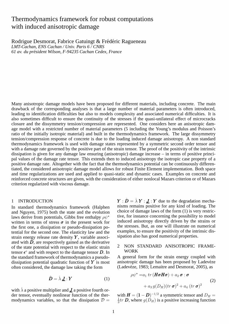
Thermodynamics framework for robust computations with induced anisotropic damage Rodrigue Desmorat, Fabrice Gatuingt & Fr´ ed´ eric Ragueneau LMT-Cachan, ENS Cachan / Univ. Paris 6 / CNRS 61 av. du pr´ esident Wilson, F-94235 Cachan Cedex, France Many anisotropic damage models have been proposed for different materials, including concrete. The main drawback of the corresponding analyses is that a large number of material parameters is often introduced, leading to identification difficulties but also to models complexity and associated numerical difficulties. It is also sometimes difficult to ensure the continuity of the stresses if the quasi-unilateral effect of microcracks closure and the dissymmetry tension/compression are represented. One considers here an anisotropic dam- age model with a restricted number of material parameters (5 including the Young’s modulus and Poisson’s ratio of the initially isotropic material) and built in the thermodynamics framework. The large dissymmetry tension/compression response of concrete is due to the loading induced damage anisotropy. A non standard thermodynamics framework is used with damage states represented by a symmetric second order tensor and with a damage rate governed by the positive part of the strain tensor. The proof of the positivity of the intrinsic dissipation is given for any damage law ensuring (anisotropic) damage increase – in terms of positive princi- pal values of the damage rate tensor. This extends then to induced anisotropy the isotropic case property of a positive damage rate. Altogether with the fact that the thermodynamics potential can be continuously differen- tiated, the considered anisotropic damage model allows for robust Finite Element implementation. Both space and time regularizations are used and applied to quasi-static and dynamic cases. Examples on concrete and reinforced concrete structures are given, with the consideration of either nonlocal Mazars criterion or of Mazars criterion regularized with viscous damage. 1 INTRODUCTION In standard thermodynamics framework (Halphen and Nguyen, 1975) both the state and the evolution laws derive from potentials, Gibbs free enthalpy ρψ ⋆ written in terms of stress σ in the present work for the first one, a dissipation or pseudo-dissipation po- tential for the second one. The elasticity law and the strain energy release rate density Y , variable associ- ated with D, are respectively gained as the derivative of the state potential with respect to the elastic strain tensor ǫ e and with respect to the damage tensor D. In the standard framework of thermodynamics a pseudo- dissipation potential quadratic function of Y is most often considered, the damage law taking the form ˙ D = ˙ λJ J J : Y (1) with ˙ λ a positive multiplier and J J J a positive fourth or- der tensor, eventually nonlinear function of the ther- modynamics variables, so that the dissipation D = Y : ˙ D = ˙ λY : J J J : Y due to the degradation mecha- nisms remains positive for any kind of loading. The choice of damage laws of the form (1) is very restric- tive, for instance concerning the possibility to model induced anisotropy directly driven by the strains or the stresses. But, as one will illustrate on numerical examples, to ensure the positivity of the intrinsic dis- sipation also has good numerical properties. 2 NON STANDARD ANISOTROPIC FRAME- WORK A general form for the strain energy coupled with anisotropic damage has been proposed by Ladev` eze (Ladev` eze, 1983; Lemaitre and Desmorat, 2005), as ρψ ⋆ =a 1 tr (HσHσ)+ a 2 σ : σ + a 3 g (D H )(trσ) 2 + a 4 (trσ) 2 (2) with H = (1 − D) −1/2 a symmetric tensor and D H = 1 3 trD, where g (D H ) is a positive increasing function 1

Welcome message from author
This document is posted to help you gain knowledge. Please leave a comment to let me know what you think about it! Share it to your friends and learn new things together.
Transcript
Thermodynamics framework for robust computationswith induced anisotropic damage
Rodrigue Desmorat, Fabrice Gatuingt & Frederic RagueneauLMT-Cachan, ENS Cachan / Univ. Paris 6 / CNRS61 av. du president Wilson, F-94235 Cachan Cedex, France
Many anisotropic damage models have been proposed for different materials, including concrete. The maindrawback of the corresponding analyses is that a large number of material parameters is often introduced,leading to identification difficulties but also to models complexity and associated numerical difficulties. It isalso sometimes difficult to ensure the continuity of the stresses if the quasi-unilateral effect of microcracksclosure and the dissymmetry tension/compression are represented. One considers here an anisotropic dam-age model with a restricted number of material parameters (5including the Young’s modulus and Poisson’sratio of the initially isotropic material) and built in the thermodynamics framework. The large dissymmetrytension/compression response of concrete is due to the loading induced damage anisotropy. A non standardthermodynamics framework is used with damage states represented by a symmetric second order tensor andwith a damage rate governed by the positive part of the straintensor. The proof of the positivity of the intrinsicdissipation is given for any damage law ensuring (anisotropic) damage increase – in terms of positive princi-pal values of the damage rate tensor. This extends then to induced anisotropy the isotropic case property of apositive damage rate. Altogether with the fact that the thermodynamics potential can be continuously differen-tiated, the considered anisotropic damage model allows forrobust Finite Element implementation. Both spaceand time regularizations are used and applied to quasi-static and dynamic cases. Examples on concrete andreinforced concrete structures are given, with the consideration of either nonlocal Mazars criterion or of Mazarscriterion regularized with viscous damage.
1 INTRODUCTIONIn standard thermodynamics framework (Halphenand Nguyen, 1975) both the state and the evolutionlaws derive from potentials, Gibbs free enthalpyρψ⋆
written in terms of stressσσσ in the present work forthe first one, a dissipation or pseudo-dissipation po-tential for the second one. The elasticity law and thestrain energy release rate densityYYY , variable associ-ated withDDD, are respectively gained as the derivativeof the state potential with respect to the elastic straintensorǫǫǫe and with respect to the damage tensorDDD. Inthe standard framework of thermodynamics a pseudo-dissipation potential quadratic function ofYYY is mostoften considered, the damage law taking the form
DDD = λ JJJ : YYY (1)
with λ a positive multiplier andJJJ a positive fourth or-der tensor, eventually nonlinear function of the ther-modynamics variables, so that the dissipationD =
YYY : DDD = λ YYY : JJJ : YYY due to the degradation mecha-nisms remains positive for any kind of loading. Thechoice of damage laws of the form (1) is very restric-tive, for instance concerning the possibility to modelinduced anisotropy directly driven by the strains orthe stresses. But, as one will illustrate on numericalexamples, to ensure the positivity of the intrinsic dis-sipation also has good numerical properties.
2 NON STANDARD ANISOTROPIC FRAME-WORK
A general form for the strain energy coupled withanisotropic damage has been proposed by Ladeveze(Ladeveze, 1983; Lemaitre and Desmorat, 2005), as
ρψ⋆ =a1 tr (HHHσσσHHHσσσ) + a2 σσσ : σσσ
+ a3 g(DH)(tr σσσ)2 + a4 (tr σσσ)2
(2)
withHHH = (111−DDD)−1/2 a symmetric tensor andDH =1
3tr DDD, whereg(DH) is a positive increasing function
1
of DH , 1/(1 − ηDH) for example, and where theai
(a1 ≥ 0, a3 ≥ 0) as well asη > 0 are material pa-rameters. The first term of Eq. (2) can take different– non equivalent – forms (Ladeveze, 1983; Papa andTalierco, 1996; Lemaitre and Desmorat, 2005),
a1 tr(
HHHσσσDHHHσσσD)
(3)
ora1
[
tr (HHHσσσ+HHHσσσ+) + 〈σσσ〉−
: 〈σσσ〉−
]
(4)
or
a1
[
tr(
HHHσσσD+HHHσσσ
D+
)
+⟨
σσσD⟩
−:⟨
σσσD⟩
−
]
(5)
allowing in the last case for the mechanical rep-resentation of the quasi-unilateral effect of micro-defects closure, withσσσ+ (resp.σσσD
+) a special posi-tive part (Ladeveze, 1983; Desmorat, 2000) built fromthe eigenvalues and the eigenvectors ofHHHσσσ (resp. ofHHHσσσD) and with〈.〉
−the negative part in terms of prin-
cipal components of a tensor. Two examples of strainenergy densities are a first one based on a splittingdeviatoric / hydrostatic quantities (withE andν theYoung’s modulus and Poisson’s ratio of the undam-aged material),
ρψ⋆ =1 + ν
2Etr(
HHHσσσDHHHσσσD)
+1− 2ν
6E
(tr σσσ)2
1− ηDH(6)
a second one based on the feature of a constantν/Eratio,
ρψ⋆ =1
2Etr (HHHσσσHHHσσσ) +
ν
2E
(
σσσ : σσσ− (tr σσσ)2)
(7)
Concerning the evolution laws, many non stan-dard damage laws can be formulated for inducedanisotropy (Mazars et al., 1990; Dragon and Halm,1996; Lemaitre et al., 2000; Billardon and Petry,2005), with second order tensorial damage rate pro-portional
• to the positive part of the strain tensor〈ǫǫǫ〉+
or to〈ǫǫǫ〉α
+with α a damage exponent,
• to the absolute value of the plastic strain tensorǫǫǫp, to the positive part ofǫǫǫp, or to any linear com-binationα |ǫǫǫp|+ (1− α) 〈ǫǫǫp〉
+,
• to a power2s of the stress tensor,
• to a linear combinationα 〈σσσ〉2+
+ (1 − α) 〈σσσ〉2−
(eventually at the powers) where to takeα = 1will lead to the modeling of the unilateral dam-age effect of no damage growth in compression,and to take1/2 < α < 1 will lead to the mod-eling of the quasi-unilateral damage effect of adamage growth in compression smaller than intension.
Induced damage anisotropy governed by the posi-tive extensions is adapted to quasi-brittle materials asconcrete. The other expressions will allow to gener-alize to induced anisotropy Lemaitre’s damage lawD = (Y/S)sp of a damage rate governed by the ac-cumulated plastic strain ratep and enhanced by thestrain energyY = 1
2ǫǫǫe :EEE : ǫǫǫe, withEEE Hooke’s tensor.
As possible generalization, one has
DDD =
(
Y
S
)s[
α |ǫǫǫp|+ (1− α) 〈ǫǫǫp〉+
]
(8)
DDD =
(
α 〈σσσ〉2+
+ (1− α) 〈σσσ〉2−
2ES
)s
p (9)
whereE denotes the Young’s modulus andS andsthe damage parameters. For more details on ductiledamage, refer to (Lemaitre and Desmorat, 2005).
The next question will be wether one automaticallycan ensure the positvity of the dissipation with thesimple feature of a positive (tensorial) damage rateDDD.
3 POSITIVITY OF THE INTRINSIC DISSIPA-TION
Previous elastic energy densities can be continuouslydifferentiated as
dρψ⋆ = ǫǫǫe : dσσσ+YYY : dDDD (10)
or
dρψ⋆ =[2a1 (HHHσσσHHH) + 2a2 σσσ + 2a3 g(DH) tr σσσ 111
+2a4 tr σσσ 111] : dσσσ+ 2a1 (σσσHHHσσσ) : dHHH
+1
3a3 g
′(DH)(tr σσσ)2 tr dDDD
(11)
leading to a dissipation due to damage mechanismsexpressed as
D =YYY : DDD= 2a1 (σσσHHHσσσ) : HHH+1
3a3 g
′(DH)(tr σσσ)2 tr DDD
(12)For the elastic energy densities written with the terms(3) or (5), the first term2a1 (σσσHHHσσσ) : HHH must be re-placed by2a1
(
σσσDHHHσσσD)
: HHH or 2a1 (σσσ+HHHσσσ+) : HHH or2a1
(
σσσD+HHHσσσ
D+
)
: HHH. These terms are next syntheticallywritten 2a1 (sssHHHsss) : HHH. With any damage law lead-ing to a positive damage rate tensor, i.e. with posi-tives eigenvalues(DDD)J , the termtr DDD =
∑
3
J=1(DDD)J
is positive so that13a3 g
′(DH)(tr σσσ)2 tr DDD ≥ 0. It isimportant to precise that the eigenvalues(DDD)J of DDD
2
are not the derivativesDJ of the eigenvalues ofDDD(except in the particular case whereDDD andDDD have thesame principal directions), the positivity of the eigen-values(DDD)J nevertheless implies the increase of theeigenvalues ofDDD.
Concerning the term2a1(sssHHHsss) : HHH, note that theexpressionHHH = (111 −DDD)−1/2 rewritten in terms ofprincipal components
HJ =1√
1−DJ
(13)
gives positive increasing eigenvaluesHJ of tensorHHHwhich is then also positive and increasing during anydamage process. The positivity of the symmetric ma-trix (sssHHHsss) is gained by seeking the sign of its eigen-values, denotedχ, solution of (sssHHHsss)~g = χ~g, with~g the corresponding eigenvectors. The eigenvaluesχare equivalently solution of
(HHHsss)2~g = χHHH~g (14)
with obviously(HHHsss)2 a positive matrix. These eigen-values take the form
χ =~gT (HHHsss)2~g
~gTHHH~g(15)
and, as ratio of positive terms, are positive. Last, thetensorial product of two symmetric positive tensors(sssHHHsss) andHHH being positive, one can conclude to thepositivity of the intrinsic dissipationD for any damag-ing loading, monotonic or not, uniaxial or multiaxial,proportional or non proportional... at the simple con-dition extended here to anisotropic damage that thedamage rateDDD must remain a positive tensor. Consid-ering conversely the set of states represented by de-viatoric tensorsσσσ = σσσD, the dissipation reduced to2a1 (sssHHHsss) : HHH ≥ 0 ∀ (sssHHHsss) ≥ 000 leads toHHH ≥ 000,therefore to the fact thatDDD ≥ 000 is a necessary andsufficient condition for the positivity of the dissipa-tion due to damageD = YYY : DDD.
4 ANISOTROPIC DAMAGE MODEL FOR CON-CRETE
An anisotropic damage model has been proposed forconcrete in previous non standard thermodynamicsframework (Desmorat, 2004; Desmorat et al., 2007)introducing a single damage variable, a second ordertensor, as the representation of the damage state dueto microcracking. Mainly due to induced anisotropy,the dissymmetric response of concrete in tension andin compression is obtained with a low number of ma-terial parameters: 2 for elasticity, 1 as damage thresh-old, 2 for damage evolution. Mazars strain damagecriterion (Mazars, 1984) is used in this initial model,with the advantage of simplicity for instance at thenumerical level.
4.1 Induced anisotropic damage modelFor concrete, the microcracks due to tension aremainly orthogonal to the loading direction, when themicrocracks due to compression are mainly parallel tothe loading direction. The damage state has then to berepresented by a tensorial variableDDD either a fourthrank tensor or a second rank tensor. The use of a sec-ond order damage tensor is more convenient for prac-tical applications (as well as for the material param-eters identification) and this is the choice made here.The damage anisotropy induced by either tension orcompression is simply modeled by the considerationof damage evolution laws ensuring a damage rate pro-portional to the positive part of the strain tensor, i.e. adamage governed by the principal extensions (Mazarset al., 1990).
The full set of constitutive equations reads
• Elasticity,
ǫǫǫ =1 + ν
Eσσσ− ν
Etr σσσ 111 or ǫǫǫ =EEE−1 : σσσ (16)
• Effective stress,
σσσ =[
(111−DDD)−1/2 σσσD (111−DDD)−1/2]D
+1
3
[ 〈tr σσσ〉+1− tr DDD
+ 〈tr σσσ〉−]
111
(17)
• Damage criterionf = ǫ − κ(tr DDD), so that theconditionf < 0 −→ elastic loading or unload-ing, f = 0, f = 0 −→ damage growth, whereǫ=
√
〈ǫǫǫ〉+ : 〈ǫǫǫ〉+ is Mazars equivalent strain andwhere
κ−1(ǫ) = aA
[
arctan
(
ǫ
a
)
− arctan(κ0
a
)
]
(18)introducingκ0 as damage threshold,A anda asdamage parameters.
• Induced damage anisotropy governed by the pos-itive extensions,
DDD = λ〈ǫǫǫ〉2+ (19)
The damage multiplierλ is determined from theconsistency conditionf = 0, f = 0.
The use of a damage criterion functionf writtenin terms of strains instead of stresses allows for asimple implementation in a Finite Element computercode (Desmorat et al., 2007). Even if Euler backward
3
scheme is used, there is no need of an iterative pro-cess. Note that at the final stage of numerical imple-mentation the elasticity law needs to be inverted. Thiscan be done in a closed form as:
σσσ =(111−DDD)1/2 σσσ (111−DDD)1/2 − (111−DDD) : σσσ
3− tr DDD(111−DDD)
+1
3[(1− tr DDD)〈tr σσσ〉+ + 〈tr σσσ〉−]111
(20)
4.2 Extension to nonlocalClassical mesh dependency occurs when using previ-ous local damage model in a Finite Element code. Anonlocal regularization can be used to gain the meshindependency. One just has to replace local Mazarsstrainǫ in the damage criterionf by nonlocal Mazarsstrainǫnl and to consider as nonlocal criterion,
f = ǫnl − κ (21)
where nonlocal equivalent strain can be defined usingan integral form withW a nonlocal weight function(Pijaudier-Cabot and Bazant, 1987),
ǫnl =ǫnl(x) =1
Vr
∫
Ω
W(x − s) ǫ(s) ds
Vr =Vr(x) =
∫
Ω
W(x − s)ds
(22)
or using a second gradient form (Aifantis, 1987; Peer-lings et al., 1996),
ǫnl − c∇2ǫnl = ǫ (23)
Both the integral form (throughW) and the gradientform (throughc) introduce a characteristic lengthlc.Even if induced anisotropy is considered next, the in-troduction of a single (isotropic) internal length willprove sufficient for practical applications.
5 VISCOUS REGULARIZATION FOR IMPACTA regularization possibility for fast dynamics and im-pact consists in taking into account the strain rateeffect on the dynamic response of concrete. For in-stance, introduce a characteristic time which, alto-gether with the consideration of the laws of dynamics,will indirectly defines a characteristic length. In thepresent case of elasticity coupled with damage thiscan simply be done by introducing a viscosity lawǫv = ǫv(D) in Mazars criterion. The damage evolu-tion occurs not anymore atf = 0 but atf = ǫv > 0. Aclassical law for isotropic damage is Norton-Perzynapower law,ǫv = kD1/n, with k andn the viscosity pa-rameters. It leads to an unbounded damage rate oftentoo high at high strain rates.
It is possible to bound the damage rate, for instanceby the maximum rateD∞ = 1/τc material dependentequal to the inverse of the characteristic timeτc (Allixand Deu, 1997; Ladeveze et al., 1998). To gain thisproperty, these authors rewrite the criterion surface asf = g(ǫ)−D (with g = κ−1) and define the viscositylaw as
f = Dv > 0 Dv = −1
bln
(
D∞ − D
D∞
)
(24)
from which derives the delay-damage law, saturatingat high strain rates,
D = D∞ [1− exp (−b(g(ǫ)−D))] (25)
The viscosity parameters, material dependent, arethenD∞ andb. This regularization is defined locally(i.e. at a structure Gauss point) and is well adapted fordynamics computations. It can be extended to the caseof induced anisotropic damage by setting (Desmoratand Gatuingt, 2006):
tr DDD = D∞
[
1− exp(
−b(
κ−1(ǫ)− tr DDD))]
(26)
The full set of constitutive equations now reads
• Elasticity,
ǫǫǫ =1 + ν
Eσσσ− ν
Etr σσσ 111 or ǫǫǫ =EEE−1 : σσσ (27)
• Effective stress,
σσσ =[
(111−DDD)−1/2 σσσD (111−DDD)−1/2]D
+1
3
[ 〈tr σσσ〉+1− tr DDD
+ 〈tr σσσ〉−]
111
(28)
• Damage criterion (local)f = κ−1(ǫ)− tr DDD, us-ing the viscous regularization (24),
f ≤ 0 −→ elastic loading or unloading
f > 0 with f = −1
bln
(
D∞ − tr DDD
D∞
)
−→ damage growth
(29)
with D∞ andb the delay-damage parameters.
• Induced damage anisotropy governed by the pos-itive extensions,
DDD = λ〈ǫǫǫ〉2+ (30)
The damage multiplierλ is determined from thedamage criterion expression forf > 0 (Eq. 29).
4
The delay-damage law (25) is recovered from previ-ous equations.
Again, the numerical implementation in a Finite El-ements computer code is quite simple as – once again– it does not need an iterative process (Desmorat andGatuingt, 2006).
6 STRUCTURAL EXAMPLESThe local and nonlocal integral anisotropic damagemodel has been implemented in CEA CAST3M FiniteElement code. The anisotropic delay-damage modelhas been implemented in the explicit code LS-Dyna.The numerical scheme for the time integration isfor both cases Euler’s backward scheme but solvedexplicitly (Desmorat and Gatuingt, 2006; Desmoratet al., 2007). Finite Element examples on 3D struc-tures are given next to illustrate the model capabili-ties.
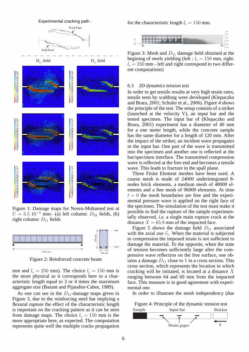
6.1 Plain concrete mixed-mode fractureThe double edge notched specimen tested by Nooru-Mohamed (Nooru-Mohamed, 1992) is analysed usingthe implementation of the model developed in the pre-vious section. The specimen is a symmetric 200 mm×200 mm mortar square with two horizontal notches,30 mm long and 5 mm thick.
The rotation of the external boundary of the plate isrestricted around the vertical axis. The concrete spec-imen is first loaded by an increasing shear (lateral)forceF (t) applied on the lateral surface. During theapplication of the shear force, the vertical displace-ment of the upper surface is totally free. In a sec-ond time, a vertical displacementU(t) is applied upto failure at constantF = FMax, the higherFMax themore curved the crack path.
The case study is here carried out for a lateral loadFMax = 10 kN. The FE discretization of the speci-men is made by the use of four node tetrahedron el-ements with one integration point. In order to per-form the computations in 3D at reasonable cost, aFE mesh with a 5 mm width is used when the realwidth of the specimen is 50 mm. The model param-eters used for the simulation are:E = 42000 MPa,ν = 0.2, κ0 = 5 10−5, A = 5 103, a = 2.93 10−4. Thenonlocal length used in the integral weight function islc = 2 mm, small value indeed justified by the factthat the material is a mortar with very small con-stituents (Bazant and Pijaudier-Cabot, 1989; Rague-neau et al., 2003). Three meshes are used: a coarsemesh with a total of 4936 elements, a medium meshwith 11294 elements, and a fine mesh with 14766elements. The characteristic length corresponds thenclose to the notch to 2 elements of the coarse mesh,to 8 elements of the medium mesh, to 14 elements ofthe fine mesh.
Figure 1 shows the anisotropic damage patterns
computed for the different meshes (at the figure top isthe cracking pattern experimentally observed (Nooru-Mohamed, 1992)). The left column corresponds to theD22 damage field, the right one to theD11 damagefield, both in nonlocal computations. They exhibit thenow classical convergence and mesh independence ofthe results obtained with a nonlocal model, here incase of anisotropic damage. The application of theshear load up toFMax yields localized damage atthe notch tip. The structural failure is then due tothe application of the vertical displacementU(t) withmainly mode I cracks represented here in the Con-tinuum Damage Mechanics framework by largeD22
values. The damage patterns computed correspondsto the crack patterns observed with the rotation of twomain cracks represented. The cracks are not perfectlysymmetric with respect to the center of the specimendue to the application of the experimental boundaryconditions.
6.2 Reinforced concrete structure
The objectives of this section are to evaluate the ro-bustness and the ability of the anisotropic damagemodel to deal with a reinforced concrete element sub-ject to flexion. The structure is a reinforced squarecross section beam, subject to three point bend load-ing. Figure 2 shows geometric features for concreteand steel. During loading, multiple loading paths areencountered in different parts of the beam: tension onthe lower part, compression on the upper part, shearnear the edge and along the reinforcing bars. The cor-responding different features of the constitutive equa-tions are activated at the same time and the occurrenceduring loading of several competitive cracks usuallymakes difficult the global convergence scheme. Forthese reasons, this case-study was part of the interna-tional MECA benchmark, launched by E.D.F. to com-pare and discriminate different 3D constitutive mod-els for concrete (Delaplace and Ghavamian, 2003).
For concrete, the material parameters used in thefollowing computations are those of previous section.For steel, elasto-plasticity with linear hardening isconsidered and the material parameters are imposedby the benchmark: Young’s modulusE = 200000MPa, Poisson ratioν = 0.3, yield stress of 480 MPa,plastic modulus of 20000 MPa. For the computation,a 3D specimen has been meshed with 2 elements inthe thickness for a total of 600 eight node parallelepi-pedic elements. Accounting for the different symme-tries of the problem, only one reinforcing steel bar ismodelled. The mean dimension of the finite elementsize is 50 mm.
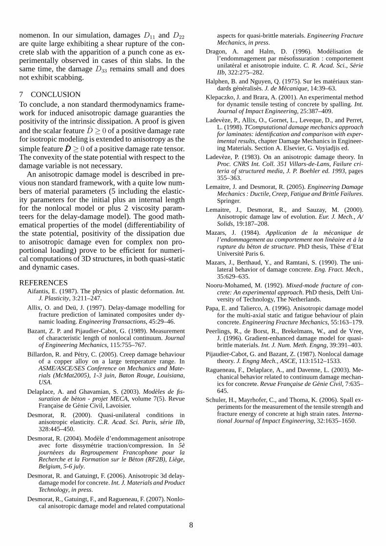
The monotonic loading is applied up to failure. Twocomputations with two different characteristic lengthsare performed in order to appreciate the effect of thenonlocal length (Gaussian weight function,lc = 150
5
Experimental cracking path :
D11 fieldD22 field
Figure 1: Damage maps for Nooru-Mohamed test atU = 3.5 10−3 mm– (a) left column:D22 fields, (b)right column:D11 fields
5 000 mm200 mm
50
0 m
m
2φ32
2φ8
Figure 2: Reinforced concrete beam
mm andlc = 250 mm). The choicelc = 150 mm isthe more physical as it corresponds here to a char-acteristic length equal to 3 or 4 times the maximumaggregate size (Bazant and Pijaudier-Cabot, 1989).
As one can see in theD11-damage maps given inFigure 3, due to the reinforcing steel bar implying aflexural rupture the effect of the characteristic lengthis important on the cracking pattern as it can be seenfrom damage maps. The choicelc = 150 mm is themore appropriate here, as expected. The computationrepresents quite well the multiple cracks propagation
for the characteristic lengthlc = 150 mm.
0.0
1.0
0.6
0.4
0.2
0.8
2
13
Figure 3: Mesh andD11 damage field obtained at thebegining of steels yielding (left :lc = 150 mm, right:lc = 250 mm - left and right correspond to two differ-ent computations)
6.3 3D dynamics tension testIn order to get tensile results at very high strain rates,tensile tests by scabbing were developed (Klepaczkoand Brara, 2001; Schuler et al., 2006). Figure 4 showsthe principle of the test. The setup consists of a striker(launched at the velocity V), an input bar and thetested specimen. The input bar of (Klepaczko andBrara, 2001) experiment has a diameter of 40 mmfor a one meter length, while the concrete samplehas the same diameter for a length of 120 mm. Afterthe impact of the striker, an incident wave propagatesin the input bar. One part of the wave is transmittedinto the specimen and another one is reflected at thebar/specimen interface. The transmitted compressionwave is reflected at the free end and becomes a tensilewave. This leads to fracture in the spall plane.
Three Finite Element meshes have been used. Acoarse mesh is made of 24000 underintegrated 8-nodes brick elements, a medium mesh of 48000 el-ements and a fine mesh of 96000 elements. At timet = 0 the mesh boundaries are free and the experi-mental pressure wave is applied on the right face ofthe specimen. The simulation of the test must make itpossible to find the rupture of the sample experimen-tally observed,i.e. a single main rupture crack at thedistanceX = 65.8 mm of the impacted face.
Figure 5 shows the damage fieldD11 associatedwith the axial axe~e1. When the material is subjectedto compression the imposed strain is not sufficient todamage the material. To the opposite, when the stateof tension becomes sufficiently large after the com-pressive wave reflection on the free surface, one ob-tains a damageD11 close to 1 in a cross section. Thiscross section, which represents the location in whichcracking will be initiated, is located at a distanceXranging between 64 and 69 mm from the impactedface. This measure is in good agreement with experi-mental one.
In order to illustrate the mesh independency (due
Figure 4: Principle of the dynamic tension testStrickerInput barSample
Strain gages V
6
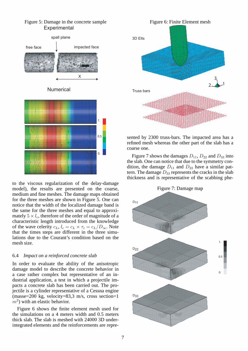
Figure 5: Damage in the concrete sample
1.
0.
0.5
Experimental
Numerical
free face
spall plane
impacted face
X
to the viscous regularization of the delay-damagemodel), the results are presented on the coarse,medium and fine meshes. The damage maps obtainedfor the three meshes are shown in Figure 5. One cannotice that the width of the localized damage band isthe same for the three meshes and equal to approxi-mately5× lc, therefore of the order of magnitude of acharacteristic length introduced from the knowledgeof the wave celeritycL, lc = cL × τc = cL/D∞. Notethat the times steps are different in the three simu-lations due to the Courant’s condition based on themesh size.
6.4 Impact on a reinforced concrete slab
In order to evaluate the ability of the anisotropicdamage model to describe the concrete behavior ina case rather complex but representative of an in-dustrial application, a test in which a projectile im-pacts a concrete slab has been carried out. The pro-jectile is a cylinder representative of a Cessna engine(masse=200 kg, velocity=83,3 m/s, cross section=1m2) with an elastic behavior.
Figure 6 shows the finite element mesh used forthe simulations on a 4 meters width and 0.5 metersthick slab. The slab is meshed with 24000 3D under-integrated elements and the reinforcements are repre-
Figure 6: Finite Element mesh
1
3
2
3D Elts
Truss bars
sented by 2300 truss-bars. The impacted area has arefined mesh whereas the other part of the slab has acoarse one.
Figure 7 shows the damagesD11,D22 andD33 intothe slab. One can notice that due to the symmetry con-dition, the damageD11 andD22 have a similar pat-tern. The damageD33 represents the cracks in the slabthickness and is representative of the scabbing phe-
Figure 7: Damage map
1.
0.
0.5
D11
D22
D33
7
nomenon. In our simulation, damagesD11 andD22
are quite large exhibiting a shear rupture of the con-crete slab with the apparition of a punch cone as ex-perimentally observed in cases of thin slabs. In thesame time, the damageD33 remains small and doesnot exhibit scabbing.
7 CONCLUSIONTo conclude, a non standard thermodynamics frame-work for induced anisotropic damage guaranties thepositivity of the intrinsic dissipation. A proof is givenand the scalar featureD ≥ 0 of a positive damage ratefor isotropic modeling is extended to anisotropy as thesimple featureDDD ≥ 0 of a positive damage rate tensor.The convexity of the state potential with respect to thedamage variable is not necessary.
An anisotropic damage model is described in pre-vious non standard framework, with a quite low num-bers of material parameters (5 including the elastic-ity parameters for the initial plus an internal lengthfor the nonlocal model or plus 2 viscosity param-teers for the delay-damage model). The good math-ematical properties of the model (differentiability ofthe state potential, positivity of the dissipation dueto anisotropic damage even for complex non pro-portional loading) prove to be efficient for numeri-cal computations of 3D structures, in both quasi-staticand dynamic cases.
REFERENCESAifantis, E. (1987). The physics of plastic deformation.Int.
J. Plasticity, 3:211–247.
Allix, O. and Deu, J. (1997). Delay-damage modelling forfracture prediction of laminated composites under dy-namic loading.Engineering Transactions, 45:29–46.
Bazant, Z. P. and Pijaudier-Cabot, G. (1989). Measurementof characteristic length of nonlocal continuum.Journalof Engineering Mechanics, 115:755–767.
Billardon, R. and Petry, C. (2005). Creep damage behaviourof a copper alloy on a large temperature range. InASME/ASCE/SES Conference on Mechanics and Mate-rials (McMat2005), 1-3 juin, Baton Rouge, Louisiana,USA.
Delaplace, A. and Ghavamian, S. (2003).Modeles de fis-suration de beton - projet MECA, volume 7(5). RevueFrancaise de Genie Civil, Lavoisier.
Desmorat, R. (2000). Quasi-unilateral conditions inanisotropic elasticity.C.R. Acad. Sci. Paris, serie IIb,328:445–450.
Desmorat, R. (2004). Modele d’endommagement anisotropeavec forte dissymetrie traction/compression. In5ejourneees du Regroupement Francophone pour laRecherche et la Formation sur le Beton (RF2B), Liege,Belgium, 5-6 july.
Desmorat, R. and Gatuingt, F. (2006). Anisotropic 3d delay-damage model for concrete.Int. J. Materials and ProductTechnology, in press.
Desmorat, R., Gatuingt, F., and Ragueneau, F. (2007). Nonlo-cal anisotropic damage model and related computational
aspects for quasi-brittle materials.Engineering FractureMechanics, in press.
Dragon, A. and Halm, D. (1996). Modelisation del’endommagement par mesofissuration : comportementunilateral et anisotropie induite.C. R. Acad. Sci., SerieIIb, 322:275–282.
Halphen, B. and Nguyen, Q. (1975). Sur les materiaux stan-dards generalises.J. de Mecanique, 14:39–63.
Klepaczko, J. and Brara, A. (2001). An experimental methodfor dynamic tensile testing of concrete by spalling.Int.Journal of Impact Engineering, 25:387–409.
Ladeveze, P., Allix, O., Gornet, L., Leveque, D., and Perret,L. (1998).TComputational damage mechanics approachfor laminates: identification and comparison with exper-imental results, chapter Damage Mechanics in Engineer-ing Materials. Section A. Elsevier, G. Voyiadjis ed.
Ladeveze, P. (1983). On an anisotropic damage theory. InProc. CNRS Int. Coll. 351 Villars-de-Lans, Failure cri-teria of structured media, J. P. Boehler ed. 1993, pages355–363.
Lemaitre, J. and Desmorat, R. (2005).Engineering DamageMechanics : Ductile, Creep, Fatigue and Brittle Failures.Springer.
Lemaitre, J., Desmorat, R., and Sauzay, M. (2000).Anisotropic damage law of evolution.Eur. J. Mech., A/Solids, 19:187–208.
Mazars, J. (1984).Application de la mecanique del’endommagement au comportement non lineaire eta larupture du beton de structure. PhD thesis, These d’EtatUniversite Paris 6.
Mazars, J., Berthaud, Y., and Ramtani, S. (1990). The uni-lateral behavior of damage concrete.Eng. Fract. Mech.,35:629–635.
Nooru-Mohamed, M. (1992).Mixed-mode fracture of con-crete: An experimental approach. PhD thesis, Delft Uni-versity of Technology, The Netherlands.
Papa, E. and Talierco, A. (1996). Anisotropic damage modelfor the multi-axial static and fatigue behaviour of plainconcrete.Engineering Fracture Mechanics, 55:163–179.
Peerlings, R., de Borst, R., Brekelmans, W., and de Vree,J. (1996). Gradient-enhanced damage model for quasi-brittle materials.Int. J. Num. Meth. Engng, 39:391–403.
Pijaudier-Cabot, G. and Bazant, Z. (1987). Nonlocal damagetheory.J. Engng Mech., ASCE, 113:1512–1533.
Ragueneau, F., Delaplace, A., and Davenne, L. (2003). Me-chanical behavior related to continuum damage mechan-ics for concrete.Revue Francaise de Genie Civil, 7:635–645.
Schuler, H., Mayrhofer, C., and Thoma, K. (2006). Spall ex-periments for the measurement of the tensile strength andfracture energy of concrete at high strain rates.Interna-tional Journal of Impact Engineering, 32:1635–1650.
8
Related Documents