Thermite powder ignition by localized microwaves Yehuda Meir, Eli Jerby ⇑ Faculty of Engineering, Tel Aviv University, Ramat Aviv 69978, Israel article info Article history: Received 3 October 2011 Received in revised form 10 January 2012 Accepted 12 February 2012 Available online 10 March 2012 Keywords: Thermite Microwave heating Hotspots Thermal runaway Ignition abstract This paper presents a new method to ignite pure thermite powder by low-power microwaves (100 W). In this method, the microwave energy is supplied locally to the powder. It creates a confined hotspot, and initiates a self-propagating combustion in the entire powder volume. The coupled thermal–electromag- netic interaction evolved within the powder prior to its ignition is simulated theoretically, taking into account the powder’s temperature-dependent parameters. The simulation results show a thermal- runaway instability and localized heating within a confined hotspot, induced mostly by the microwave’s electric-field component. The experimental setup employs accordingly an open-end applicator imple- mented by a miniature solid-state microwave-drill device inserted into the thermite powder as a local igniter. The experimental results show ignition within 3 s at 2.1-GHz, 100-W microwave injection, in agreement with the theoretical model. The dependence of the minimal microwave power on the expo- sure time required to reach combustion is identified. Practical aspects and potential applications of this mechanism, such as rust conversion, energy production, and propulsion are indicated. Ó 2012 The Combustion Institute. Published by Elsevier Inc. All rights reserved. 1. Introduction Exothermic thermite reactions occur between metal-oxides and metals in powder mixtures. For example, the reaction between magnetite and aluminum [1], 3Fe 3 O 4 þ 8Al ! 9Fe þ 4Al 2 O 3 þ 3:67 kJ=g; ð1Þ produces iron and alumina, and releases energy comparable to TNT explosion. Thermite reactions are of interest for a variety of applica- tions, such as explosives (e.g. for automotive air-bag safety sys- tems), cutting and welding of metals, and processing of ceramics and composite materials [2–4]. The thermite reaction is an environ- mental-friendly energy source [5], and it can be utilized as a fuel in oxygen-free environments such as underwater due to the inherent zero oxygen balance of the thermite reaction (1). The thermite’s flame temperature (4057 K theoretically in ideal adiabatic conditions [6]) is significantly higher than that of hydro- carbon fuels. However, it is much harder to ignite thermite than common explosives [7]. This difficulty is alleviated in practice by additives (e.g. calcium peroxide) [8] which reduce the ignition temperature of the thermite, but also deteriorate its quality. Hence, there is a considerable motivation to develop practical means to ignite pure thermites. Laser beams were found effective for ignition of thermite pow- ders [9]. Pre-heating of thermites also improves their combustion speeds [10]. Electrostatic discharges were studied as a means to ignite aluminum powders [11]. Thermite ignition by high-power microwaves was reported using a 75-GHz, 50 kW gyrotron pulse [12]. In more general, microwaves were found effective for flame enhancement and stabilization [13]. A volumetric ignition of Fe 3 O 4 –Al thermite by a magnetic (H-field) coupling in a 2-kW microwave cavity was investigated as a means to initiate self- propagating high-temperature synthesis (SHS) for sintering of ceramic composites [14]. The magnetic (H-field) coupling of micro- waves to powders made of non-magnetic metals was discovered as an effective heating mechanism [15]. This permeability-like effect in the macroscopic level is attributed to the eddy currents induced in the metallic particles [16]. The intentional concentration of microwave energy into a small hotspot (much smaller than the microwave’s wavelength) within the heated object was studied in the context of the microwave-drill invention [17]. The microwave’s self-focusing mechanism involves a thermal-runaway instability in which the dissipated energy is confined within the hotspot, hence the localized heating acceler- ates its temperature rise [18] and leads inevitably to the hotspot’s phase transition (e.g. melting, evaporation, or breakdown [19]). This localized microwave-heating mechanism is studied experi- mentally and theoretically in the next sections as a means to ignite pure thermite powders. 2. Conceptual scheme A simplified scheme of the localized microwave applicator employed for the thermite ignition in this study is illustrated in 0010-2180/$ - see front matter Ó 2012 The Combustion Institute. Published by Elsevier Inc. All rights reserved. doi:10.1016/j.combustflame.2012.02.015 ⇑ Corresponding author. E-mail address: [email protected] (E. Jerby). Combustion and Flame 159 (2012) 2474–2479 Contents lists available at SciVerse ScienceDirect Combustion and Flame journal homepage: www.elsevier.com/locate/combustflame

Welcome message from author
This document is posted to help you gain knowledge. Please leave a comment to let me know what you think about it! Share it to your friends and learn new things together.
Transcript

Combustion and Flame 159 (2012) 2474–2479
Contents lists available at SciVerse ScienceDirect
Combustion and Flame
journal homepage: www.elsevier .com/locate /combustflame
Thermite powder ignition by localized microwaves
Yehuda Meir, Eli Jerby ⇑Faculty of Engineering, Tel Aviv University, Ramat Aviv 69978, Israel
a r t i c l e i n f o
Article history:Received 3 October 2011Received in revised form 10 January 2012Accepted 12 February 2012Available online 10 March 2012
Keywords:ThermiteMicrowave heatingHotspotsThermal runawayIgnition
0010-2180/$ - see front matter � 2012 The Combustdoi:10.1016/j.combustflame.2012.02.015
⇑ Corresponding author.E-mail address: [email protected] (E. Jerby).
a b s t r a c t
This paper presents a new method to ignite pure thermite powder by low-power microwaves (�100 W).In this method, the microwave energy is supplied locally to the powder. It creates a confined hotspot, andinitiates a self-propagating combustion in the entire powder volume. The coupled thermal–electromag-netic interaction evolved within the powder prior to its ignition is simulated theoretically, taking intoaccount the powder’s temperature-dependent parameters. The simulation results show a thermal-runaway instability and localized heating within a confined hotspot, induced mostly by the microwave’selectric-field component. The experimental setup employs accordingly an open-end applicator imple-mented by a miniature solid-state microwave-drill device inserted into the thermite powder as a localigniter. The experimental results show ignition within �3 s at 2.1-GHz, 100-W microwave injection, inagreement with the theoretical model. The dependence of the minimal microwave power on the expo-sure time required to reach combustion is identified. Practical aspects and potential applications of thismechanism, such as rust conversion, energy production, and propulsion are indicated.
� 2012 The Combustion Institute. Published by Elsevier Inc. All rights reserved.
1. Introduction
Exothermic thermite reactions occur between metal-oxides andmetals in powder mixtures. For example, the reaction betweenmagnetite and aluminum [1],
3Fe3O4 þ 8Al! 9Feþ 4Al2O3 þ 3:67 kJ=g; ð1Þ
produces iron and alumina, and releases energy comparable to TNTexplosion. Thermite reactions are of interest for a variety of applica-tions, such as explosives (e.g. for automotive air-bag safety sys-tems), cutting and welding of metals, and processing of ceramicsand composite materials [2–4]. The thermite reaction is an environ-mental-friendly energy source [5], and it can be utilized as a fuel inoxygen-free environments such as underwater due to the inherentzero oxygen balance of the thermite reaction (1).
The thermite’s flame temperature (4057 K theoretically in idealadiabatic conditions [6]) is significantly higher than that of hydro-carbon fuels. However, it is much harder to ignite thermite thancommon explosives [7]. This difficulty is alleviated in practice byadditives (e.g. calcium peroxide) [8] which reduce the ignitiontemperature of the thermite, but also deteriorate its quality. Hence,there is a considerable motivation to develop practical means toignite pure thermites.
Laser beams were found effective for ignition of thermite pow-ders [9]. Pre-heating of thermites also improves their combustionspeeds [10]. Electrostatic discharges were studied as a means to
ion Institute. Published by Elsevier
ignite aluminum powders [11]. Thermite ignition by high-powermicrowaves was reported using a 75-GHz, 50 kW gyrotron pulse[12]. In more general, microwaves were found effective for flameenhancement and stabilization [13]. A volumetric ignition ofFe3O4–Al thermite by a magnetic (H-field) coupling in a 2-kWmicrowave cavity was investigated as a means to initiate self-propagating high-temperature synthesis (SHS) for sintering ofceramic composites [14]. The magnetic (H-field) coupling of micro-waves to powders made of non-magnetic metals was discovered asan effective heating mechanism [15]. This permeability-like effectin the macroscopic level is attributed to the eddy currents inducedin the metallic particles [16].
The intentional concentration of microwave energy into a smallhotspot (much smaller than the microwave’s wavelength) withinthe heated object was studied in the context of the microwave-drillinvention [17]. The microwave’s self-focusing mechanism involvesa thermal-runaway instability in which the dissipated energy isconfined within the hotspot, hence the localized heating acceler-ates its temperature rise [18] and leads inevitably to the hotspot’sphase transition (e.g. melting, evaporation, or breakdown [19]).This localized microwave-heating mechanism is studied experi-mentally and theoretically in the next sections as a means to ignitepure thermite powders.
2. Conceptual scheme
A simplified scheme of the localized microwave applicatoremployed for the thermite ignition in this study is illustrated in
Inc. All rights reserved.

Thermite powder
Combustion propagation
Intense E-field Hotspot
Coaxial waveguide
MicrowaveInput port
Open-endapplicator
z
r
BC
Fig. 1. A conceptual illustration of the thermite powder ignition by localizedmicrowaves radiated by an open-end applicator. The tip inserted into the powderconcentrates the electric-field lines intensely, and creates a hotspot by a thermal-runaway instability. The thermite is heated locally up to its ignition temperature.Once ignited, the self-sustained combustion propagates in the entire powdervolume (BC denotes boundary conditions presented in Section 3).
Y. Meir, E. Jerby / Combustion and Flame 159 (2012) 2474–2479 2475
Fig. 1. The microwave energy is delivered by a coaxial waveguideto an open-end applicator with a center electrode slightly insertedinto the thermite powder. As in the microwave-drill interaction[17], the self-focused microwave energy is absorbed mostly nearthe center-electrode tip hence the electric field is most intensethere (this localization effect is not significantly affected by thepowder’s further boundary conditions). Consequently, a thermal-runaway process is evolved and a hotspot is formed there withinthe thermite mixture. The thermally unstable hotspot evolved isheated up to the thermite’s ignition temperature, thus initiatinga self-propagating combustion process within the entire volumeof the thermite powder.
3. Localized microwave-heating simulation
The pre-combustion heating phase of the thermite ignition ismodeled here by the coupled thermal–electromagnetic equations[18]. The simulation model imported from Ref. [18] is extendedhere to include the magnetic heating effect (neglected in Ref.[18]) in addition to the electric-field heating. The model is appliedhere to the thermite powder in the 2-D circularly-symmetricalgeometry illustrated in Fig. 1. The processed material is situatedin an open metallic box, represented by boundary conditions(BC) of a perfect electric conductor (PEC) for the electromagnetic(EM) wave. The EM wave is irradiated locally via the coaxial appli-cator. The thermal BC is presented by a thin metal wall surroundedby air hence it is almost isolated due to the relatively small heatconvection through it.
The coupled EM-wave and heat equations are presented in atwo-time-scale approach in the form
r� ½ðl0r � jl00r Þ�1r� ~E� � ½e0r � jðe00r þ r=xe0Þ�k2
0~E ¼ 0; ð2Þ
qCp@T=@t �r � ðkthrTÞ ¼ Q ; ð3Þ
where the dependent variables are ~E, the electric-field vector com-ponent of the EM wave, and T, the temperature, both in r–z coordi-nates. The electric field is presented in the frequency domain, wherex and k0 are its angular frequency and free-space wave-number,respectively. The thermite powder is represented by its tempera-ture-dependent parameters, lr, er, r, q, Cp, and kth, wherelr ¼ l0r � jl00r and er ¼ e0r � je00r are its complex relative magnetic per-meability and dielectric permittivity, respectively, and r is its elec-tric conductivity. In the heat equation (3), q, Cp and kth are thedensity, the heat capacity, and the thermal conductivity, respec-tively, of the relevant material at each point (the analysis takes into
account the actual parameters of the thermite powder, the tungstenelectrode, and the surrounding air).
The temperature T is varying slowly with respect to the EMwave. The distinction between the typical time scales of the EMwave propagation (�1 ns) and the slower thermal evolution(>1 ms) allows the two-time scale approximation. Its validity isverified by the heuristic condition qCpd2
hs=kth � s, where dhs isthe hotspot width and s = 2p/x is the wave period. The EM band-width is sufficiently narrow to neglect any parametric variationwith frequency hence the wave equation (2) is solved in the fre-quency domain while the heat equation (3) is computed in theslowly-varying time domain. Eqs. (2) and (3) are coupled togetherby the local EM heat dissipation,
Q ¼ 12ðrþxe0e00r Þj~Ej
2 þxl0l00r j~Hj
2h i
; ð4Þ
and by the consequent variations in the material’s parameters dueto the temperature rise. The second term in the right-hand side ofEq. (4) represents the magnetic heating, where~H ¼ jðxl0lrÞ
�1r� ~E is the magnetic vector components of theEM field. As the temperature rises, the spatial variations in er, lr
and r modify the microwave radiation pattern hence enabling theself-focusing effect. The temperature evolution is initiated at roomtemperature uniformly in the entire region. Since the simulationdoes not include phase changes, it is halted at the melting temper-ature of the aluminum component of the mixture (933 K).
The temperature-dependent parameters of the mixed powder(namely its thermal conductivity, heat capacity, density, permittiv-ity, and permeability) are estimated by the parameters of its rawingredients, taking into account the particle sizes and mixing ratio.The powder simulation employs the Heat-Transfer and Radio-Fre-quency (RF) modules of the COMSOL Multiphysics� software pack-age. The temperature-dependent parameters of the aluminumpowder component er1, lr1 are derived from [20] for mono-sized37 lm diameter spheres in a body centered cubic (BCC) structure,in the relevant temperature range. Its thermal conductivity is de-rived by simulating the temperature gradient generated by a stea-dy-state heating of a thin layer of aluminum powder, withboundary conditions of a constant temperature on one surfaceand a constant heat flux on the other one. Its heat capacity is sim-ulated by a uniform heating source within isolating boundaryconditions.
The temperature-dependent permittivity and permeability ofthe magnetite powder, er2, lr2, are imported from the literaturefor <75 lm [21] and 38–62 lm [22] particle-size powders at highdensity. Their thermal-conductivity and heat-capacity parametersare taken from [23] and [24], respectively. The dielectric loss-tan-gent of the magnetite varies from 0.07 at room temperature to 1.0at 900 K. The aluminum powder exhibits a smaller absorption inmagnetic coupling, and its dielectric coupling is negligible here.The thermite mixture is simulated as a homogeneous powder ofspherical aluminum and magnetite particles uniformly distributedin a 1:1 volumetric fraction ratio. The contact resistance betweenthe powder’s particles [25] is assumed to be negligibly large (sim-ulated as small air gaps between particles). The weighted complexpermittivity and permeability of the thermite mixture are derivedby Lichtenecker logarithmic mixture rule [26], as
er ¼ffiffiffiffiffiffiffiffiffiffiffiffier1er2p
; lr ¼ffiffiffiffiffiffiffiffiffiffiffiffiffiffilr1lr2
p: ð5a;bÞ
Figure 2 shows the resulted dielectric and thermal parametersof the thermite powder in the range from room temperature upto the aluminum melting point (933 K). The results show thatthe dielectric loss increases and the thermal conductivity decreaseswith the temperature rise, hence enabling the thermal-runawayinstability induced by the electric field component. The effect ofthe different particle sizes presented in Fig. 2a for two size
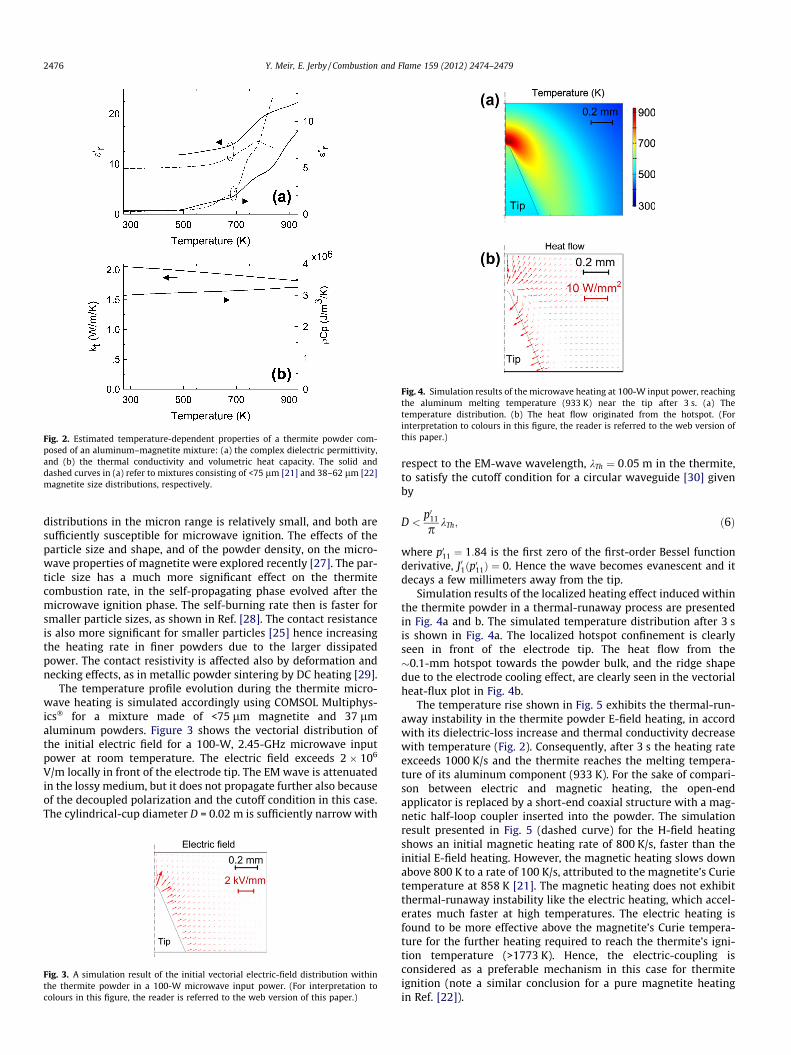
Fig. 2. Estimated temperature-dependent properties of a thermite powder com-posed of an aluminum–magnetite mixture: (a) the complex dielectric permittivity,and (b) the thermal conductivity and volumetric heat capacity. The solid anddashed curves in (a) refer to mixtures consisting of <75 lm [21] and 38–62 lm [22]magnetite size distributions, respectively.
Fig. 4. Simulation results of the microwave heating at 100-W input power, reachingthe aluminum melting temperature (933 K) near the tip after 3 s. (a) Thetemperature distribution. (b) The heat flow originated from the hotspot. (Forinterpretation to colours in this figure, the reader is referred to the web version ofthis paper.)
2476 Y. Meir, E. Jerby / Combustion and Flame 159 (2012) 2474–2479
distributions in the micron range is relatively small, and both aresufficiently susceptible for microwave ignition. The effects of theparticle size and shape, and of the powder density, on the micro-wave properties of magnetite were explored recently [27]. The par-ticle size has a much more significant effect on the thermitecombustion rate, in the self-propagating phase evolved after themicrowave ignition phase. The self-burning rate then is faster forsmaller particle sizes, as shown in Ref. [28]. The contact resistanceis also more significant for smaller particles [25] hence increasingthe heating rate in finer powders due to the larger dissipatedpower. The contact resistivity is affected also by deformation andnecking effects, as in metallic powder sintering by DC heating [29].
The temperature profile evolution during the thermite micro-wave heating is simulated accordingly using COMSOL Multiphys-ics� for a mixture made of <75 lm magnetite and 37 lmaluminum powders. Figure 3 shows the vectorial distribution ofthe initial electric field for a 100-W, 2.45-GHz microwave inputpower at room temperature. The electric field exceeds 2 � 106
V/m locally in front of the electrode tip. The EM wave is attenuatedin the lossy medium, but it does not propagate further also becauseof the decoupled polarization and the cutoff condition in this case.The cylindrical-cup diameter D = 0.02 m is sufficiently narrow with
Fig. 3. A simulation result of the initial vectorial electric-field distribution withinthe thermite powder in a 100-W microwave input power. (For interpretation tocolours in this figure, the reader is referred to the web version of this paper.)
respect to the EM-wave wavelength, kTh ¼ 0:05 m in the thermite,to satisfy the cutoff condition for a circular waveguide [30] givenby
D <p011
pkTh; ð6Þ
where p011 ¼ 1:84 is the first zero of the first-order Bessel functionderivative, J01ðp011Þ ¼ 0. Hence the wave becomes evanescent and itdecays a few millimeters away from the tip.
Simulation results of the localized heating effect induced withinthe thermite powder in a thermal-runaway process are presentedin Fig. 4a and b. The simulated temperature distribution after 3 sis shown in Fig. 4a. The localized hotspot confinement is clearlyseen in front of the electrode tip. The heat flow from the�0.1-mm hotspot towards the powder bulk, and the ridge shapedue to the electrode cooling effect, are clearly seen in the vectorialheat-flux plot in Fig. 4b.
The temperature rise shown in Fig. 5 exhibits the thermal-run-away instability in the thermite powder E-field heating, in accordwith its dielectric-loss increase and thermal conductivity decreasewith temperature (Fig. 2). Consequently, after 3 s the heating rateexceeds 1000 K/s and the thermite reaches the melting tempera-ture of its aluminum component (933 K). For the sake of compari-son between electric and magnetic heating, the open-endapplicator is replaced by a short-end coaxial structure with a mag-netic half-loop coupler inserted into the powder. The simulationresult presented in Fig. 5 (dashed curve) for the H-field heatingshows an initial magnetic heating rate of 800 K/s, faster than theinitial E-field heating. However, the magnetic heating slows downabove 800 K to a rate of 100 K/s, attributed to the magnetite’s Curietemperature at 858 K [21]. The magnetic heating does not exhibitthermal-runaway instability like the electric heating, which accel-erates much faster at high temperatures. The electric heating isfound to be more effective above the magnetite’s Curie tempera-ture for the further heating required to reach the thermite’s igni-tion temperature (>1773 K). Hence, the electric-coupling isconsidered as a preferable mechanism in this case for thermiteignition (note a similar conclusion for a pure magnetite heatingin Ref. [22]).
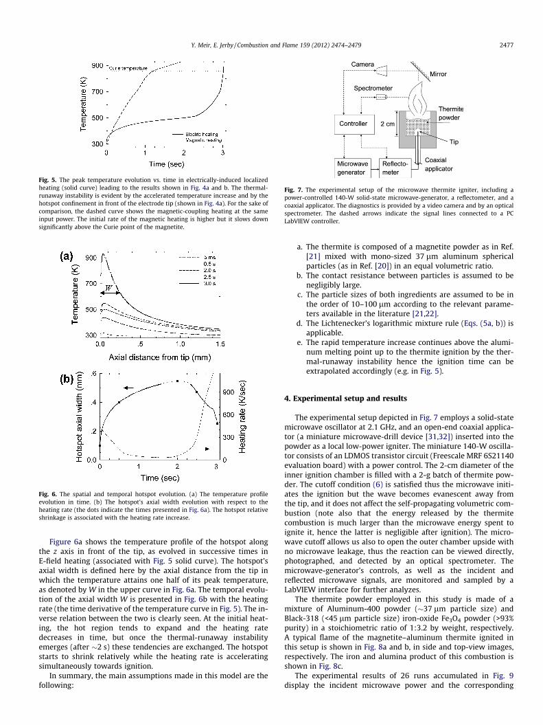
Fig. 5. The peak temperature evolution vs. time in electrically-induced localizedheating (solid curve) leading to the results shown in Fig. 4a and b. The thermal-runaway instability is evident by the accelerated temperature increase and by thehotspot confinement in front of the electrode tip (shown in Fig. 4a). For the sake ofcomparison, the dashed curve shows the magnetic-coupling heating at the sameinput power. The initial rate of the magnetic heating is higher but it slows downsignificantly above the Curie point of the magnetite.
Fig. 6. The spatial and temporal hotspot evolution. (a) The temperature profileevolution in time. (b) The hotspot’s axial width evolution with respect to theheating rate (the dots indicate the times presented in Fig. 6a). The hotspot relativeshrinkage is associated with the heating rate increase.
Fig. 7. The experimental setup of the microwave thermite igniter, including apower-controlled 140-W solid-state microwave-generator, a reflectometer, and acoaxial applicator. The diagnostics is provided by a video camera and by an opticalspectrometer. The dashed arrows indicate the signal lines connected to a PCLabVIEW controller.
Y. Meir, E. Jerby / Combustion and Flame 159 (2012) 2474–2479 2477
Figure 6a shows the temperature profile of the hotspot alongthe z axis in front of the tip, as evolved in successive times inE-field heating (associated with Fig. 5 solid curve). The hotspot’saxial width is defined here by the axial distance from the tip inwhich the temperature attains one half of its peak temperature,as denoted by W in the upper curve in Fig. 6a. The temporal evolu-tion of the axial width W is presented in Fig. 6b with the heatingrate (the time derivative of the temperature curve in Fig. 5). The in-verse relation between the two is clearly seen. At the initial heat-ing, the hot region tends to expand and the heating ratedecreases in time, but once the thermal-runaway instabilityemerges (after �2 s) these tendencies are exchanged. The hotspotstarts to shrink relatively while the heating rate is acceleratingsimultaneously towards ignition.
In summary, the main assumptions made in this model are thefollowing:
a. The thermite is composed of a magnetite powder as in Ref.[21] mixed with mono-sized 37 lm aluminum sphericalparticles (as in Ref. [20]) in an equal volumetric ratio.
b. The contact resistance between particles is assumed to benegligibly large.
c. The particle sizes of both ingredients are assumed to be inthe order of 10–100 lm according to the relevant parame-ters available in the literature [21,22].
d. The Lichtenecker’s logarithmic mixture rule (Eqs. (5a, b)) isapplicable.
e. The rapid temperature increase continues above the alumi-num melting point up to the thermite ignition by the ther-mal-runaway instability hence the ignition time can beextrapolated accordingly (e.g. in Fig. 5).
4. Experimental setup and results
The experimental setup depicted in Fig. 7 employs a solid-statemicrowave oscillator at 2.1 GHz, and an open-end coaxial applica-tor (a miniature microwave-drill device [31,32]) inserted into thepowder as a local low-power igniter. The miniature 140-W oscilla-tor consists of an LDMOS transistor circuit (Freescale MRF 6S21140evaluation board) with a power control. The 2-cm diameter of theinner ignition chamber is filled with a 2-g batch of thermite pow-der. The cutoff condition (6) is satisfied thus the microwave initi-ates the ignition but the wave becomes evanescent away fromthe tip, and it does not affect the self-propagating volumetric com-bustion (note also that the energy released by the thermitecombustion is much larger than the microwave energy spent toignite it, hence the latter is negligible after ignition). The micro-wave cutoff allows us also to open the outer chamber upside withno microwave leakage, thus the reaction can be viewed directly,photographed, and detected by an optical spectrometer. Themicrowave-generator’s controls, as well as the incident andreflected microwave signals, are monitored and sampled by aLabVIEW interface for further analyzes.
The thermite powder employed in this study is made of amixture of Aluminum-400 powder (�37 lm particle size) andBlack-318 (<45 lm particle size) iron-oxide Fe3O4 powder (>93%purity) in a stoichiometric ratio of 1:3.2 by weight, respectively.A typical flame of the magnetite–aluminum thermite ignited inthis setup is shown in Fig. 8a and b, in side and top-view images,respectively. The iron and alumina product of this combustion isshown in Fig. 8c.
The experimental results of 26 runs accumulated in Fig. 9display the incident microwave power and the corresponding
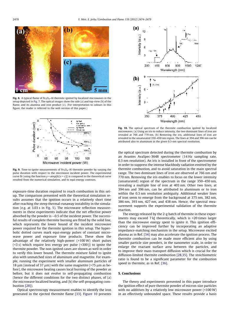
Fig. 8. A typical flame of Fe3O4–Al thermite ignited by localized microwaves in thesetup depicted in Fig. 7. The optical images show the side (a) and top-view (b) of theflame, and its alumina and iron product (c). (For interpretation to colours in thisfigure, the reader is referred to the web version of this paper.)
Fig. 9. Time-to-ignite measurements of Fe3O4–Al thermite powder by varying thepulse duration with respect to the microwave incident power. The experimentalcurve fit (using the function y = aexp[b/(x + c)]) is compared to the theoretical curveresulted from the numerical simulation, and to equi-energy contours.
Fig. 10. The optical spectrum of the thermite combustion ignited by localizedmicrowaves. (a) Using an iris to reduce intensity, the two dominant lines of iron arerevealed at 766 and 770 nm. (b) Removing the iris, additional lines of iron arerevealed in the unsaturated 350–450 nm region. The lines at 394 and 396 nm can beattributed also to aluminum in the given 0.3-nm spectral resolution.
2478 Y. Meir, E. Jerby / Combustion and Flame 159 (2012) 2474–2479
exposure-time duration required to reach combustion in this set-up. The comparison presented with the theoretical simulation re-sults assumes that the ignition occurs in a relatively short timeafter reaching the steep thermal-runaway instability in the simula-tion (e.g. at 3.03 s in Fig. 5). The microwave reflection measure-ments in these experiments indicate that the net effective powerabsorbed by the powder is �0.5 of the incident power. The success-ful results of complete thermite burning are fitted by the solid line,which represents the lower bound of the incident microwavepower required for the thermite ignition in this setup. The hyper-bolic dotted curves mark equi-energy pulses of constant micro-wave power and exposure time products. These show theadvantage of the relatively high-power (>100 W) short pulses(<3 s) which require less energy per pulse (<300 J) to ignite thethermite powder. The non-ignited cases are shown as well in orderto verify this lower bound. The thermite mixture failed to ignitealso with unmatched sizes of aluminum and magnetite. For exam-ple, running the experiment with smaller aluminum particles of18 lm (instead of 37 lm) with the same magnetite (>75 lm as be-fore), the microwave heating causes local burning of the powder asbefore, but it does not evolve to self-propagating combustion(hence the different conditions for the two distinct phases, of (a)the microwave localized heating, and (b) the self-propagating com-bustion [28]).
Optical spectroscopy measurement enables to identify the irongenerated in the ejected thermite flame [33]. Figure 10 presents
the optical spectrum detected during the thermite combustion byan Avantes AvaSpec-3648 spectrometer (14 Hz sampling rate,0.3 nm resolution). An iris is installed in front of the spectrometerin order to suppress the intense blackbody radiation emitted by thethermite combustion, and to avoid saturation in the main spectralrange. The two dominant lines of iron are observed at 766 nm and770 nm. Removing the iris enables to focus on the lower intensity(unsaturated) region of the spectrum in the range 350–450 nm,revealing a multiple line of iron at 403 nm. Other two lines, at394 nm and 396 nm, can be attributed to aluminum or to ironwithin the 0.3 nm resolution ambiguity. Additional weaker linesof iron seem to emerge from the background at 375 nm, 382 nm,386 nm, 393 nm, 427 nm, and 438 nm. Hence, the spectral mea-surement supports the experimental validation of the thermitereaction.
The energy released by the 2-g batch of thermite in these exper-iments may exceed 7 kJ theoretically, which is >20 times largerthan the microwave energy spent to ignite it. This ignition effi-ciency can be improved further by incorporating an adaptiveimpedance-matching mechanism in the setup. Microwave excitedplasma as in Ref. [34] may also accelerate the ignition process. Thethermite combustion can be made more efficient also by usingsmaller particle size powders, in the nanometer scale, in order toenlarge the reactant surface area between the particles, andto improve their mass transport diffusion which is crucial for thediffusion-limited thermite combustion [28,35]. The stoichiometricratio is found to be a significant parameter for the combustionspeed in thermite, as in Ref. [36].
5. Conclusions
The theory and experiments presented in this paper introducethe ignition effect of pure thermite powder of micron-size particleswith no additives by a relatively low microwave power (<100 W)in an effectively unbounded space. These results provide a basis

Y. Meir, E. Jerby / Combustion and Flame 159 (2012) 2474–2479 2479
for a practical method to ignite pure thermite powders for applica-tions in various scales (from a �1-g batch and larger).
Depending on the coupling by an open or short-end applicator,the microwave absorption by the thermite is attributed either tothe electric or to the magnetic field component, respectively. Asseen in Fig. 5, the magnetic heating can be more effective in thelower temperature range, below the Curie point, whereas thedielectric heating elevates more rapidly above the thermal-run-away turning point (at �700 K) up to the thermite’s ignition tem-perature (>1773 K) [37]. Hence, in order to expedite the ignition,one may conceive a sequential combination of the magnetic andelectric heating in a two-stage applicator. In this arrangement,the magnetic pre-heating will be applied first by a magnetically-coupled applicator, which will become electrically-coupled byvarying its geometry in order to enable the further heating morerapidly. This sequential mechanism can be implemented by a fus-ible short-end loop, or by a movable electrode. This approach mayshorten the ignition process significantly.
The thermite ignition method presented here is studied furtheralso for applications of melting, cutting, and welding of variousmetals, for localized direct conversion of rusty surfaces to iron(note that the thermite reaction of rust and aluminum producesiron and alumina similarly to (1)), and as a fuel in oxygen-freeenvironments. A comprehensive model shall include the contactresistance and necking effects between the powder particles (e.g.as in Refs. [38,39]). These further studies will be presented in fu-ture publications. The low-power microwave ignition techniquepresented above enables solid-state embodiments of various ther-mite igniters in compact, low-cost, silent, automatic and portabledevices. The various versatile implementations of this conceptmay open new possibilities for the practical applications men-tioned above and for material processing, explosive charge detona-tion, coating, sintering and various SHS processes, as well ascombustion and propulsion applications.
Acknowledgment
This research is supported by the Israel Science Foundationunder Grant No. 1639/11.
References
[1] L. Durães, J. Campos, A. Portugal, Prop. Explos. Pyrotech. 31 (2006) 42–49.[2] B. Ho, S. Chang-qing, Key Eng. Mater. 419–420 (2010) 393–396.
[3] Q.S. Meng, S.P. Chen, J.F. Zhao, H. Zhang, H.X. Zhang, Z.A. Munir, Mater. Sci. Eng.A 456 (2007) 332–336.
[4] L.L. Wang, Z.A. Munir, Y.M. Maximov, J. Mater. Sci. 28 (1993) 3693–3708.[5] G. Cao, R. Orrù, Chem. Eng. J. 87 (2002) 239–249.[6] S.H. Fischer, M.C. Grubelich, in: Proc. 24th Int’l Pyrotechnics Seminar,
Monterey, CA, 1998.[7] K.C. Patil, S.T. Aruna, S. Ekambaram, Curr. Opin. Solid State Mater. Sci. 2 (1997)
158–165.[8] V. Kobyakov, L. Mashkinov, M. Sichinava, High Temp. 47 (2009) 119–122.[9] M.L. Mileham, M.P. Kramer, A.E. Stiegman, J. Phys. Chem. C 111 (2007) 16883–
16888.[10] B. Dikici, M.L. Pantoya, V. Levitas, Combust. Flame 157 (2010) 1581–1585.[11] E. Beloni, E.L. Dreizin, Combust. Flame 157 (2010) 1346–1355.[12] G.M. Batanov, N.K. Bereghetskaya, V.A. Kopiev, I.A. Kossyi, A.N. Magunov, V.A.
Shcherbakov, N.V. Sachkova, Dokl. Phys. 51 (2006) 180–185.[13] E.S. Stockman, S.H. Zaidi, R.B. Miles, C.D. Carter, M.D. Ryan, Combust. Flame
156 (2009) 1453–1461.[14] C.C. Lee, N. Yoshikawa, S. Taniguchi, J. Mater. Sci. 46 (2011) 7004–7011.[15] J. Cheng, R. Roy, D. Agrawal, J. Mater. Sci. Lett. 20 (2001) 1561–1563.[16] M. Ignatenko, M. Tanaka, M. Sato, Jpn. J. Appl. Phys. 48 (2009) 067001-1–
067001-6.[17] E. Jerby, V. Dikhtyar, O. Aktushev, U. Grosglick, Science 298 (2002) 587–589.[18] E. Jerby, O. Aktushev, V. Dikhtyar, J. Appl. Phys. 97 (2005) 034909-1–034909-7.[19] V. Dikhtyar, E. Jerby, Phys. Rev. Lett. 96 (2006) 045002-1–045002-4.[20] T. Galek, K. Porath, E. Burkel, U. van Rienen, Model. Simul. Mater. Sci. Eng. 18
(2010) 025015-1–025015-13.[21] Z. Peng, J.Y. Hwang, J. Mouris, R. Hutcheon, X. Huang, ISIJ Int. 50 (2010) 1590–
1596.[22] M. Hotta, M. Hayashi, K. Nagata, ISIJ Int. 51 (2011) 491–497.[23] J. Mølgaard, W.W. Smeltzer, J. Appl. Phys. 42 (1971) 3644–3647.[24] J.P. Coughlin, E.G. King, K.R. Bonnickson, J. Am. Chem. Soc. 73 (1951) 3891–
3893.[25] G.R. Ruschau, S. Yoshikawa, R.E. Newnham, J. Appl. Phys. 72 (1992) 953–959.[26] R. Simpkin, IEEE Trans. Microw. Theory Tech. 58 (2010) 545–550.[27] M. Hotta, M. Hayashi, A. Nishikata, K. Nagata, ISIJ Int. 49 (2009) 1443–1448.[28] J.J. Granier, M.L. Pantoya, Combust. Theory Model. 8 (2004) 555–565.[29] J.R. Groza, A. Zavaliangos, Mater. Sci. Eng. A 287 (2000) 171–177.[30] R.E. Collin, Foundation for Microwave Engineering, third ed., McGraw Hill,
2001.[31] Y. Meir, A. Salzberg, E. Jerby, Hotspot induced by low-power microwave drill –
transistor-based localized heaters and their new applications, in: Proc. Ampere13th Int’l Conf., September 5–8, 2011, Toulouse, France, pp. 201–204.
[32] Y. Meir, E. Jerby, Proc. COMCAS-IEEE Int’l Conf., November 7–9, 2011, Tel Aviv,Israel, pp. 1–4.
[33] Y. Meir, E. Jerby, Microw. Opt. Technol. Lett. 53 (2011) 2281–2283.[34] E. Jerby, A. Golts, Y. Shamir, S. Wonde, J.B.A. Mitchell, J.L. LeGarrec, T.
Narayanan, M. Sztucki, D. Ashkenazi, Z. Barkay, Appl. Phys. Lett. 95 (2009)191501-1–191501-3.
[35] J.L. Cheng, H.H. Hng, H.Y. Ng, P.C. Soon, Y.W. Lee, J. Phys. Chem. Solids 71(2010) 90–94.
[36] K.B. Plantier, M.L. Pantoya, A.E. Gash, Combust. Flame 140 (2005) 299–309.[37] M. Stir, K. Ishizaki, S. Vaucher, R. Nicula, J. Appl. Phys. 105 (2009) 124901-1–
124901-4.[38] A.V. Gusarov, E.P. Kovalev, Phys. Rev. B 80 (2009) 024202-1–024202-15.[39] E. Beloni, P.R. Santhanam, E.L. Dreizin, J. Electrostat. 70 (2012) 157–165.
Related Documents