The X-Ray Tube DMI 50B Kyle Thornton

The X-Ray Tube
Dec 30, 2015
The X-Ray Tube. DMI 50B Kyle Thornton. Evolution Of The X-Ray Tube. Roentgen experimented with a Crookes tube Evacuated tube containing two electrodes Could not control the number of electrons moving between the electrons (tube current) - PowerPoint PPT Presentation
Welcome message from author
This document is posted to help you gain knowledge. Please leave a comment to let me know what you think about it! Share it to your friends and learn new things together.
Transcript
The X-Ray Tube
DMI 50B
Kyle Thornton
Evolution Of The X-Ray Tube
Roentgen experimented with a Crookes tube– Evacuated tube containing two electrodes– Could not control the number of electrons moving between the
electrons (tube current) In 1913, W.D. Coolidge redesigned the tube, calling it a
hot cathode tube– Replaced the negative electrode with a small spiral-wound
tungsten wire– Current was applied to this wire creating heat to free electrons
Hot cathode tubes became the standard for x-ray tubes

Cold Cathode X-Ray TubeEarly 20th century

Cold Cathode Tube Fluorescence

Coolidge Tube w/Stationary Anode

Helpful website
http://www.ndt-ed.org/EducationResources/HighSchool/Radiography/xraygenerators.htm
http://www.youtube.com/watch?v=Bc0eOjWkxpU
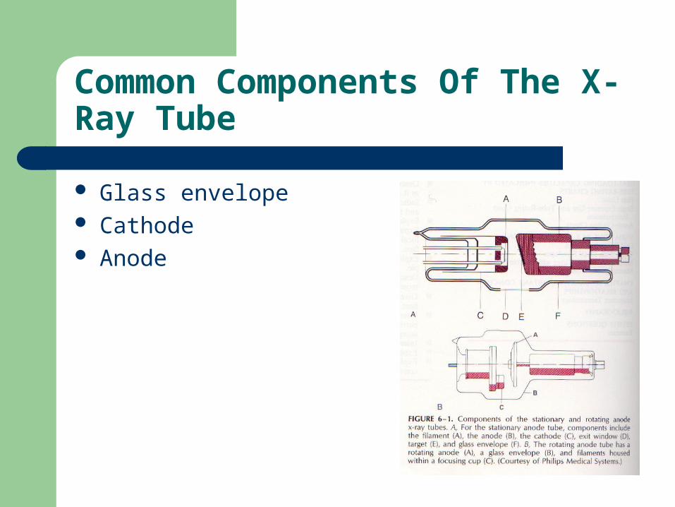
Common Components Of The X-Ray Tube
Glass envelope Cathode Anode
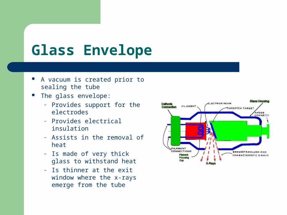
Glass Envelope
A vacuum is created prior to sealing the tube
The glass envelope: – Provides support for the
electrodes– Provides electrical insulation– Assists in the removal of heat– Is made of very thick glass to
withstand heat– Is thinner at the exit window
where the x-rays emerge from the tube

Cathode
Negative electrode of the x-ray tube
Consists of a filament and a focusing cup
The filament provides a source of electrons
Electrons are freed when the filament is heated
The filament is a long thin tungsten wire shaped into a spiral coil
Cathode
About 10 volts and 3 – 5 amperes are applied to the filament to heat it
Tungsten is used because of its high melting point - 3370° C
It is also malleable Most modern tubes contain two filaments
– The longer filament is used when large numbers of electrons are needed
– The shorter filament is used when lower tube currents and maximum detail are needed

The Focusing Cup
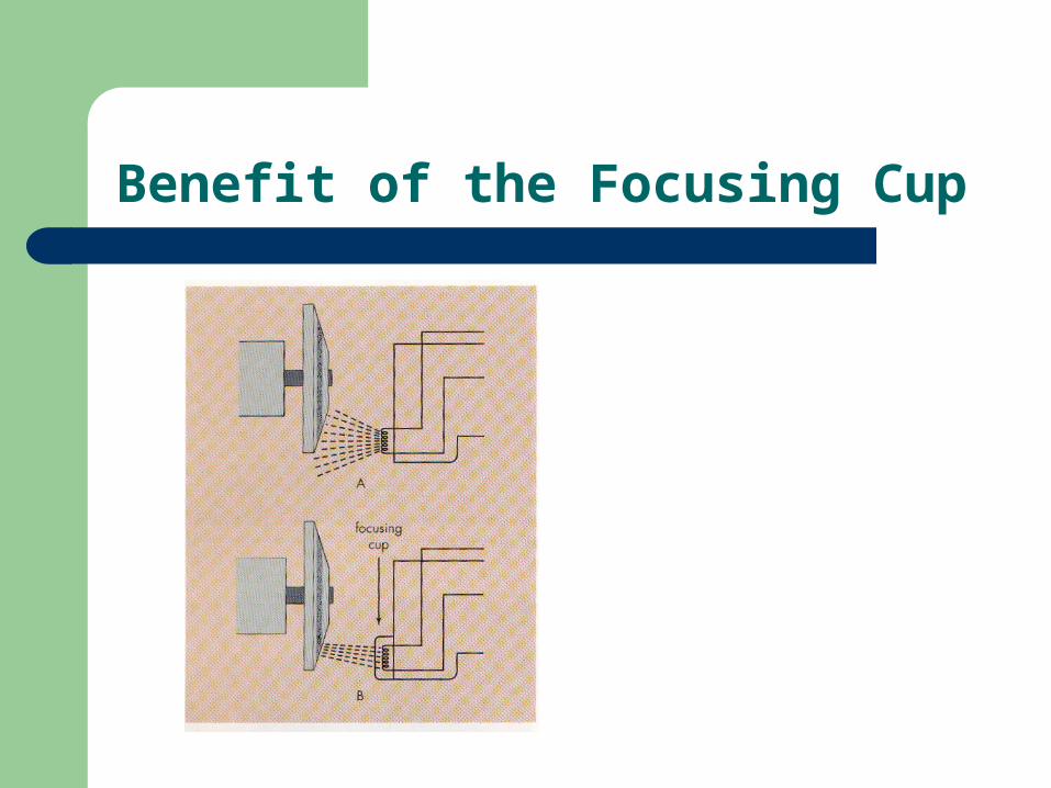
The filaments are mounted within a focusing cup Generally made of nickel, stainless steel, or
molybdenum A negative charge is placed on the focusing cup Focuses the electrons on a smaller spot of the anode This improves detail on the film
Benefit of the Focusing Cup

X-Ray Tube Focusing Cup
http://www.youtube.com/watch?v=LyWuvSZRSLc&feature=related
The Anode
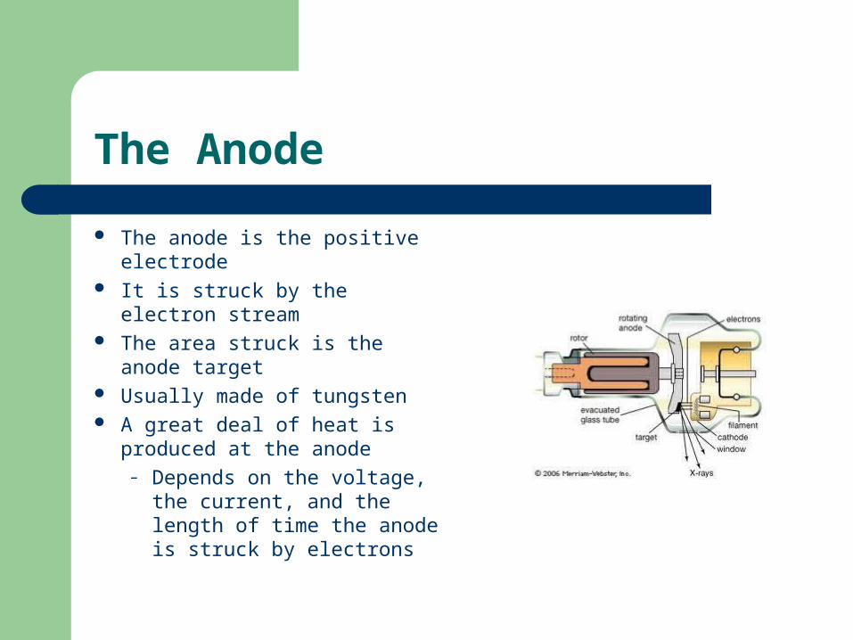
The anode is the positive electrode
It is struck by the electron stream The area struck is the anode
target Usually made of tungsten A great deal of heat is produced
at the anode– Depends on the voltage, the
current, and the length of time the anode is struck by electrons

Stationary Anodes
Used when lower heat quantities are produced Consists of a tungsten target and copper block and
stem Copper conducts the heat away from the tungsten
target The heat can damage the anode target, causing pitting
– Results in x-ray beam of reduced intensity due to scattering and absorption in the uneven surface

Rotating Anodes
The first was made by Philips Medical Systems in Holland in 1929
Consists of a tungsten alloy disk on a molybdenum base
Rotating anodes range in size from about 5 cm to 12.5 cm
Disk sizes determine the thermal load Anodes have an angle of about 7° to 20°
Rotating Anodes
Rotating anodes assure that the same area of the target being struck over and over is rare
Heat energy is distributed more evenly over the anode face
More rapid exposures are possible The rotating anode is driven by an induction
motor
Purposes Of The Anode
Serves as a positive electrode Provides structural support for the target plate Provides a means for of dissipating heat to the
target

The Benefits Of Using Tungsten As A Target Material
Malleability High melting point -
3370° C High Z number Resists vaporization at
high temperatures Ability to conduct heat
away from area of heat production
Its density Ability to absorb heat
without raising the temperature of the conductor
Its availability makes it cost-effective
The Induction Motor
Works on the principle of Lenz’ law Using opposing magnetic fields, the copper bar is
made to rotate Rotation of the anode is accomplished more efficiently
this way The anode is surrounded by electromagnets that are
switched on and off in rapid sequence Anodes utilize 60 Hz AC Anodes usually rotate at 3600 rpm
– Newer anodes may rotate at 10,000 rpm
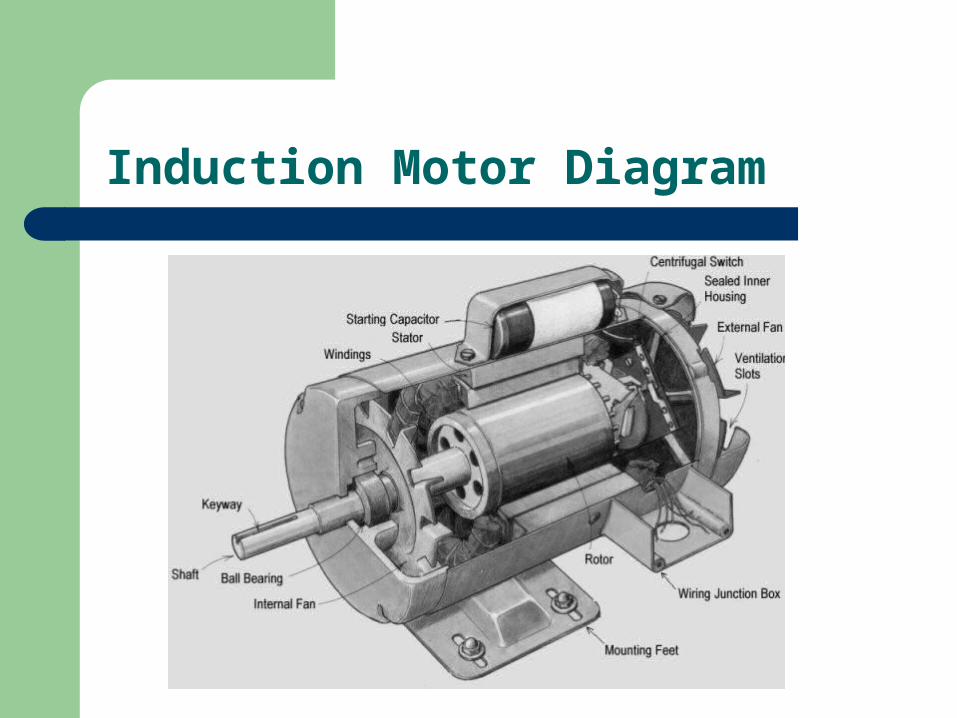
Induction Motor Diagram

Target Plate Angulation
The area of the target struck by the electron stream is the focal spot
Image sharpness is improved when the focal spot is small
By angling the target, a small area can be struck, but at the same time provides a large space for heat dissipation
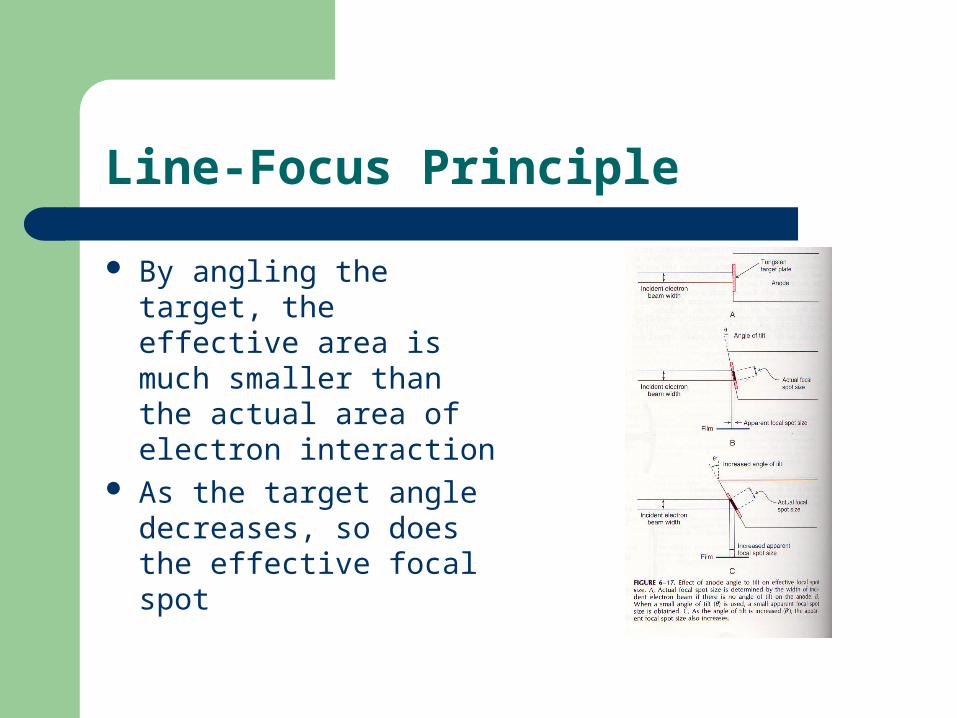
Line-Focus Principle
By angling the target, the effective area is much smaller than the actual area of electron interaction
As the target angle decreases, so does the effective focal spot
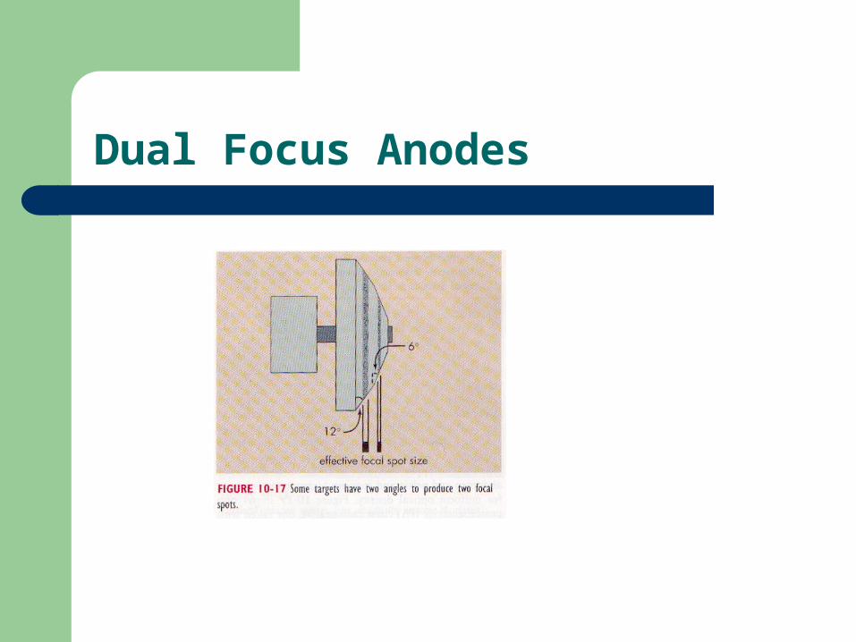
Dual Focus Anodes
Heel Effect
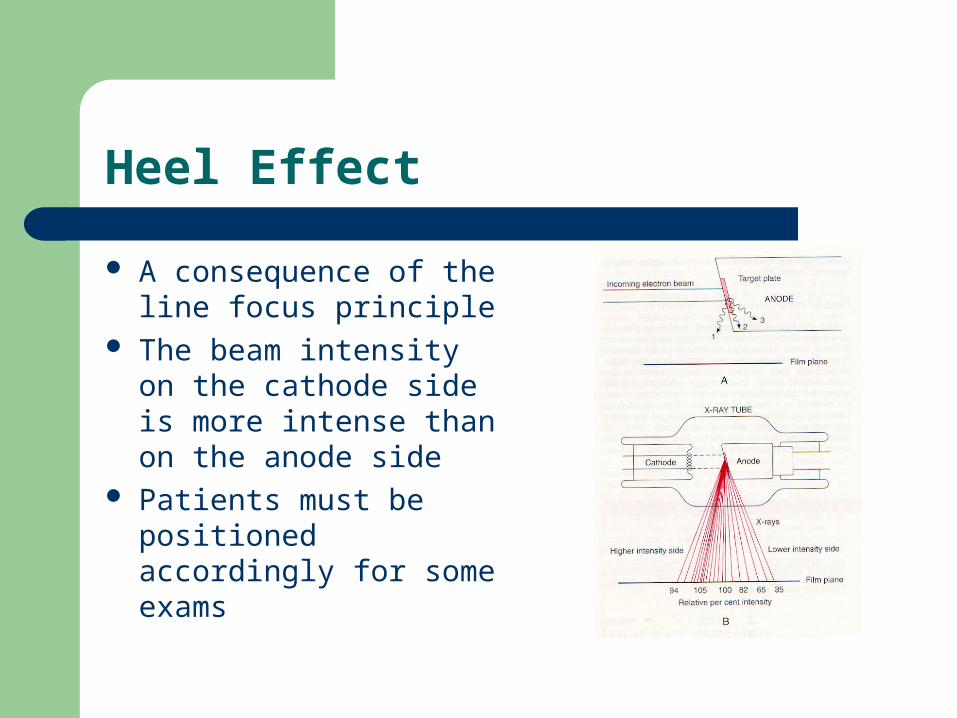
A consequence of the line focus principle
The beam intensity on the cathode side is more intense than on the anode side
Patients must be positioned accordingly for some exams

Heel Effect
Off-Focus Radiation
Off-Focus Radiation
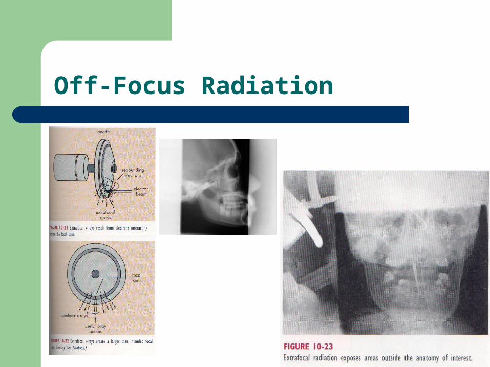
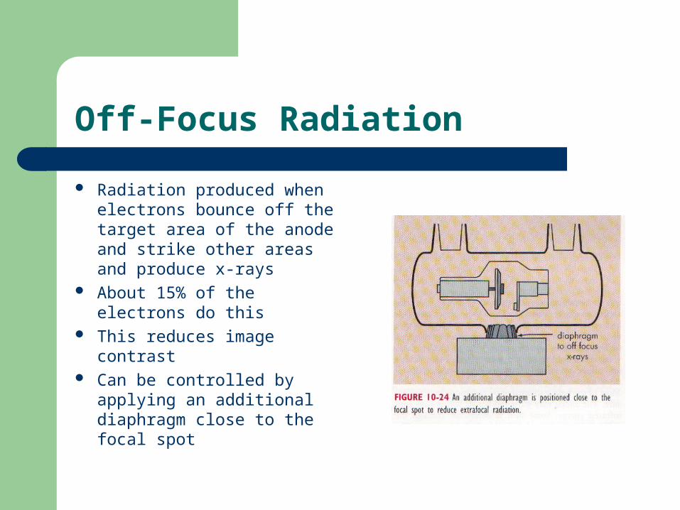
Radiation produced when electrons bounce off the target area of the anode and strike other areas and produce x-rays
About 15% of the electrons do this
This reduces image contrast Can be controlled by applying
an additional diaphragm close to the focal spot

Tube Exit Window
The useful beam is emitted from the tube exit window
This section of glass is generally much thinner than the rest of the tube

The Tube Housing
Supports and houses the x-ray tube Provides insulation Prevents shock Is lined with a lead tube shield to prevent
leakage radiation Oil surrounds the tube within the tube shielding

The Tube Housing
Causes Of X-Ray Tube Failure
A single excessive exposure Long exposure times Filament vaporization
– The most common
Safe Operation With Tube Rating Charts
Radiographic rating chart Anode cooling chart Housing cooling chart
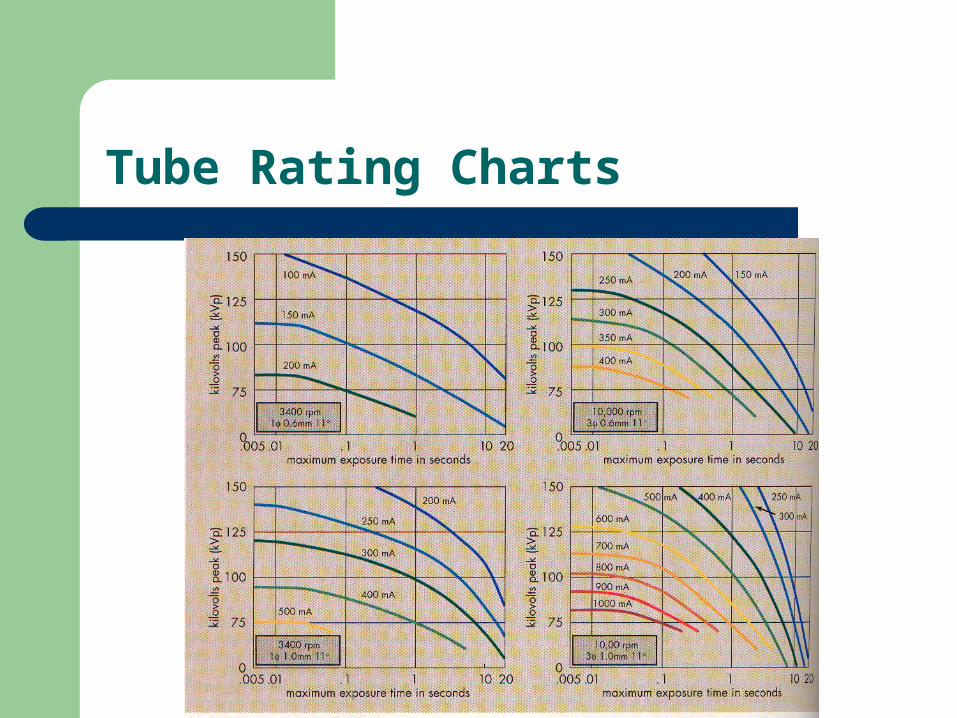
Tube Rating Charts
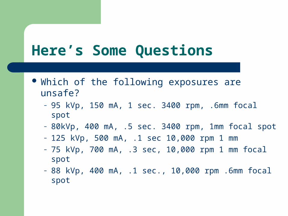
Here’s Some Questions
Which of the following exposures are unsafe?– 95 kVp, 150 mA, 1 sec. 3400 rpm, .6mm focal spot– 80kVp, 400 mA, .5 sec. 3400 rpm, 1mm focal spot– 125 kVp, 500 mA, .1 sec 10,000 rpm 1 mm– 75 kVp, 700 mA, .3 sec, 10,000 rpm 1 mm focal
spot– 88 kVp, 400 mA, .1 sec., 10,000 rpm .6mm focal
spot
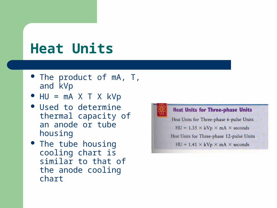
Heat Units
The product of mA, T, and kVp
HU = mA X T X kVp Used to determine
thermal capacity of an anode or tube housing
The tube housing cooling chart is similar to that of the anode cooling chart
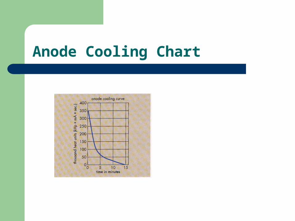
Anode Cooling Chart
Here’s Some More Questions
If 50,000 HU are delivered to the anode, how long will it take to cool completely?
How many heat units are produced if 6 films are exposed using a three phase, six pulse generator at 82 kVp and 120 mAs
Related Documents