1 X-ray Tube and Generator – Basic principles and construction Dr Slavik Tabakov - Production of X-rays and Patient Dose - X-ray tube construction - Anode - types, efficiency - Classical X-ray generator (block diagram) - Medium frequency X-ray generator (block diagram) - Principle of radiographic contrast formation - X-ray film and film/screen combination -Various radiographic contrasts (definitions) - Image Intensifier construction - Fluoroscopic image and dose OBJECTIVES

Welcome message from author
This document is posted to help you gain knowledge. Please leave a comment to let me know what you think about it! Share it to your friends and learn new things together.
Transcript
1
X-ray Tube and Generator –
Basic principles and construction
Dr Slavik Tabakov
- Production of X-rays and Patient Dose
- X-ray tube construction
- Anode - types, efficiency
- Classical X-ray generator (block diagram)
- Medium frequency X-ray generator (block diagram)
- Principle of radiographic contrast formation
- X-ray film and film/screen combination
-Various radiographic contrasts (definitions)
- Image Intensifier construction
- Fluoroscopic image and dose
OBJECTIVES

2
.
Estimated annual collective dose to UK population from Diagnostic Radiology for 1990 is approx. 20,000 manSv. On the basis of risk estimate
this could be responsible for up to 700 cancer deaths/year ! Safety in Diagnostic Radiology, IPEM, 1995
Data for mid-1980
NRPB, 1989
Approximately 90% of the total collective dose to UK population from man-made radiation sources arises from Diagnostic Radiology Safety in Diagnostic Radiology, IPEM, 1995
In most industrialised countries there are between 300 and 900 X-ray examinations for every 1000 inhabitants every year. Over half of these are chest examinations (these figures does not include dental X-ray examinations or mass screening programs).
Doses varies widely from hospital to hospital, even in the same country, sometimes by a factor of 100.
Radiation and You, EU, Luxembourg 1990
3
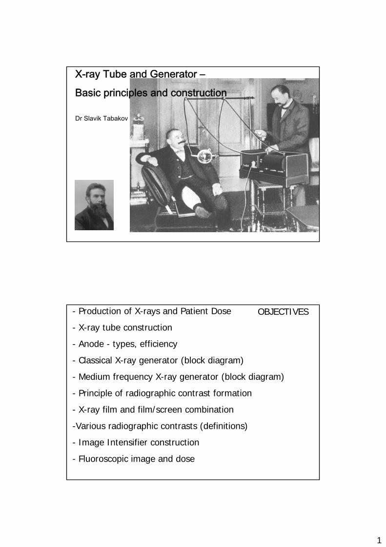
100%
0.25%
1%
2%
Distribution of X-ray dose from the Tube through the Patient to the X-ray film
Exposure ~ 80 kV, 30 mAs @ 1m
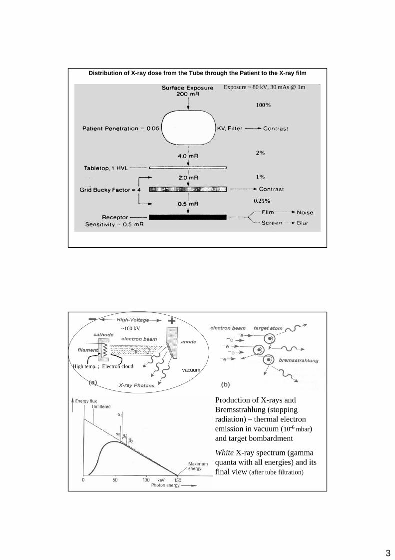
Production of X-rays and Bremsstrahlung (stopping radiation) – thermal electron emission in vacuum (10-6 mbar) and target bombardment
White X-ray spectrum (gamma quanta with all energies) and its final view (after tube filtration)
High temp. ; Electron cloud
~100 kV
vacuum
4
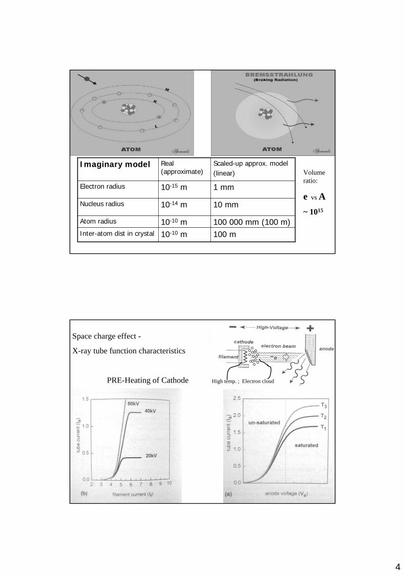
100 m10-10 mInter-atom dist in crystal
100 000 mm (100 m)10-10 mAtom radius
10 mm10-14 mNucleus radius
1 mm10-15 mElectron radius
Scaled-up approx. model(linear)
Real (approximate)
Imaginary modelVolume ratio:
e vs A~ 1015
Space charge effect -
X-ray tube function characteristics
PRE-Heating of Cathode High temp. ; Electron cloud
5
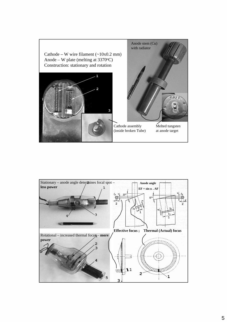
Cathode – W wire filament (~10x0.2 mm) Anode – W plate (melting at 3370oC) Construction: stationary and rotation
Cathode assembly (inside broken Tube)
Melted tungsten at anode target
Anode stem (Cu) with radiator
Stationary – anode angle determines focal spot –less power
Rotational – increased thermal focus – more power
Effective focus ; Thermal (Actual) focus
Anode angle
EF = sin α . AF

6
Anode heat - storage and dissipation (cooling)
Pmax ~ f3/2.D1/2.n1/2 / sin α
The maximal power of the rotating anode(Pmax) depends from the effective focal spot size (f); the diameter of the target track (D); the angle of the anode (α); and the speed of rotation (n - r.p.m.):
X-ray Intensity distribution:
-In all directions inside the Tube housing (only a fraction of X-rays used – output dose)
-The overall output intensity decreases with ageing of Tube
- Decreased intensity at Anode site (Heel effect) – it is more obvious with old Tubes
Intensity of X-ray radiation : W ~ I.U2.Z
Anode efficiency η ~ k.U.Z (Z-anode atom. No.)
(intensity per energy unit - η = W/I.U )
7
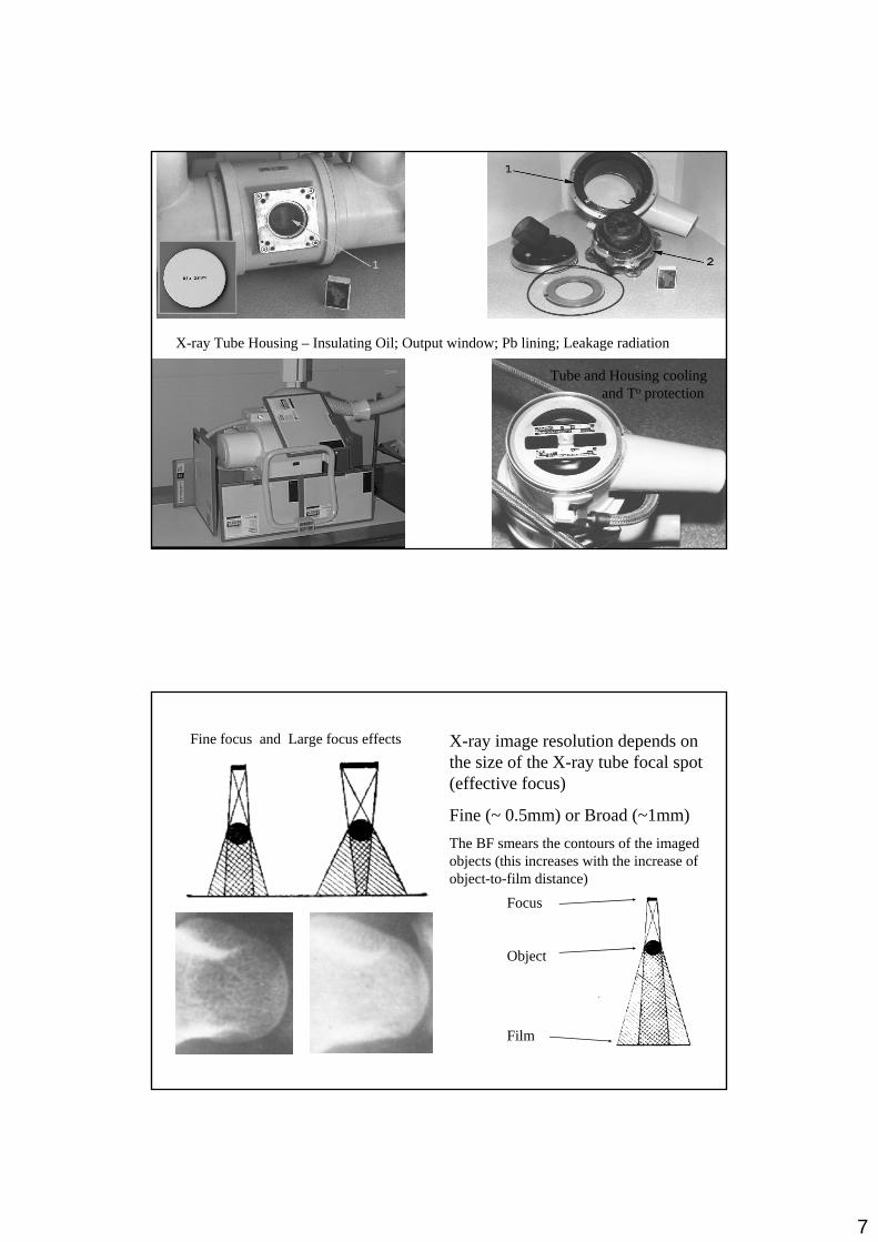
X-ray Tube Housing – Insulating Oil; Output window; Pb lining; Leakage radiation
Tube and Housing coolingand To protection
Fine focus and Large focus effects X-ray image resolution depends on the size of the X-ray tube focal spot (effective focus)
Fine (~ 0.5mm) or Broad (~1mm)The BF smears the contours of the imaged objects (this increases with the increase of object-to-film distance)
Focus
Object
Film
8
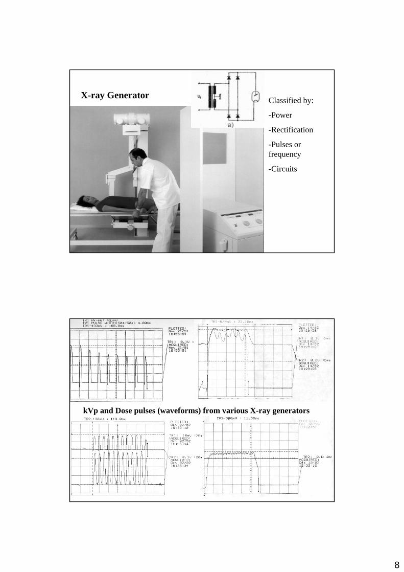
X-ray Generator Classified by:
-Power
-Rectification
-Pulses or frequency
-Circuits
kVp and Dose pulses (waveforms) from various X-ray generators
9
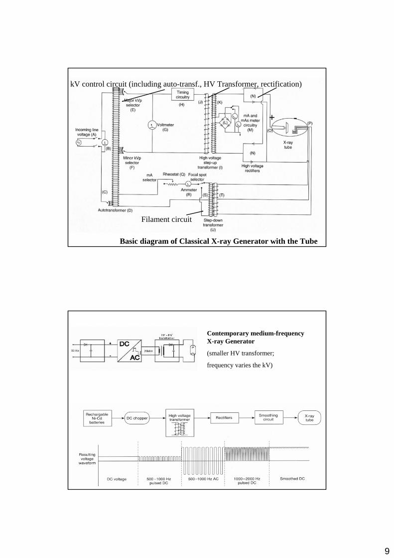
Filament circuit
kV control circuit (including auto-transf., HV Transformer, rectification)
+ -
Basic diagram of Classical X-ray Generator with the Tube
Contemporary medium-frequency X-ray Generator
(smaller HV transformer;
frequency varies the kV)

10
U / f ~ A . n voltage U with frequency f
A - cross section of the transform core;
n - number of transformer windings (transformer ratio);
(smaller HV transformer; frequency varies the kV)
Block-diagram of modern computer-controlled X-ray Generator
11
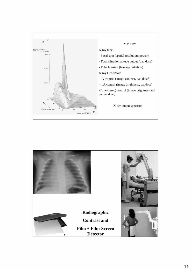
SUMMARY
X-ray tube:
- Focal spot (spatial resolution; power)
- Total filtration at tube output (pat. dose)
- Tube housing (leakage radiation)
X-ray Generator:
- kV control (image contrast, pat. dose2)
- mA control (image brightness, pat.dose)
-Time (msec) control (image brightness and patient dose)
X-ray output spectrum
Radiographic
Contrast and
Film + Film-Screen Detector

12
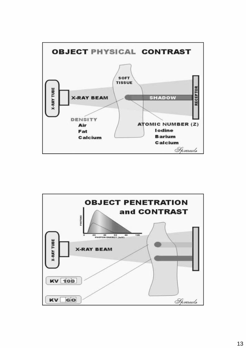
Ix = Io . e-(µ.d)
The X-ray source radiation Io passes through the object (the body) and is modulated by the body tissues (µ.d) on its way. This modulated radiation beam Ix interacts with the detector, where the modulated radiation is transformed into modulated light – the X-ray image.
The contrast of the image depends on the energy of the X-ray beam.
13
14
15
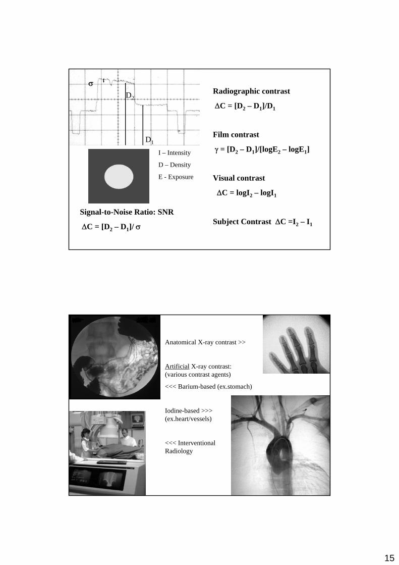
D1
D2Radiographic contrast
∆C = [D2 – D1]/D1
Film contrast
γ = [D2 – D1]/[logE2 – logE1]
Visual contrast
∆C = logI2 – logI1
Subject Contrast ∆C =I2 – I1
Signal-to-Noise Ratio: SNR
∆C = [D2 – D1]/ σ
σ
I – Intensity
D – Density
E - Exposure
Anatomical X-ray contrast >>
Artificial X-ray contrast: (various contrast agents)
<<< Barium-based (ex.stomach)
Iodine-based >>> (ex.heart/vessels)
<<< Interventional Radiology

16
X-ray film – with 1 or 2 sensitive layers (AgBr emulsions) over transparent base The film is exposed to both X-rays
and light inside the cassette
Light (X-ray) photon excites a Bromine atom (and it looses an e-). These free e- are trapped into crystal defects. The (+) Silver ions are attracted into these (–) defects, where they are neutralised and become Ag atoms (sensitised grains). The combination of areas in the film with different number ofsensitised grains forms a LATENT IMAGE. During the process of film development the sensitised grains are stabilised (the exposed AgBr crystals reduced to stable Ag atoms). During the next process of film fixing the remaining un-sensitised grains (which had not been exposed to light photons) are removed and washed out. The final visible image contains areas with various darkness (depending on the concentration of Ag atoms).

17
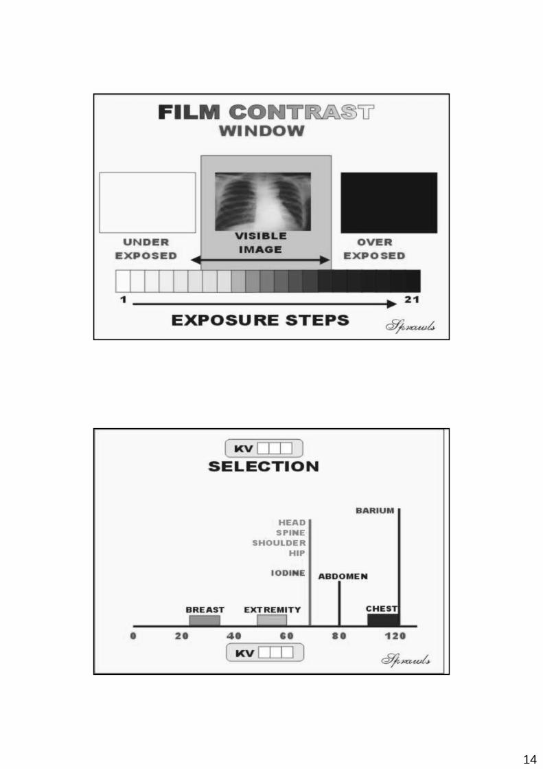
X-ray film characteristics:-Exposure latitude (dynamic range);
-Resolution (grain size)
-Sensitivity (film speed)
Cassette intensifying screen influence
Development process influence
Exposure Kilovolts (kVp)
X-ray spectrum – quality and quantity change
Change of kV leads to change of X-ray energy, Anode effectiveness, Dose and spectrum
Energy in a single exposure X ~ Z . kV2 . mAs
The X-ray anode efficiency η ~ Z. Ua
Photographic analogue:none

18
Exposure milli Ampers (mA)
X-ray spectrum – quantity change
Change of mA leads to change of X-ray intensity (with no spectrum change)
Energy in a single exposure X ~ Z . kV2 . mAs
Photographic analogue:-speed
70 kVp, 50 mAs 70 kVp, 80 mAs70 kVp, 25 mAs
mAsinfluence
70 kVp, 50 mAs 81 kVp, 50 mAs60 kVp, 50 mAs
kVpinfluence
Approx. Linear function
Approx. Square function
* Loss of Contrast

19
X-RAY FLUOROSCOPY IMAGING SYSTEMS
Fluoroscopy delivers very high patient dose. This can be illustrated with an example:
The electrical energy imparted to the anode during an exposure is A = C1 . Ua . Ia . T
The X-ray tube anode efficiency is E = C2 . Z. Ua
From the two equations follows that the energy produced in a single exposure will beX = C . A . E = C . Z . (Ua)2 . Ia . T = (C. Z) . kV2 . mAs
Radiography of the lumbar spine (with parameters 80 kV, 30 mAs):X = k. 80.80.30 = k. 192,000
Fluoroscopy - 3 minutes Barium meal (with parameters 80 kV, 1mA)X = k. 80.80.1.3.60 = k. 1,152,000
In this example fluoroscopy delivers approx. 6 times more X-ray energy (dose)

20
Luminescence:Fluorescence - emitting narrow light spectrum (very short afterglow ~nsec) -PM detectors; II input screens (CsI:Tl)
Phosphorescence - emitting broad light spectrum (light continues after radiation) -monitor screens, II output screens (ZnCdS:Ag)
The old fluoroscopic screens are no longer used due to high dose and low resolution
- Input window (Ti or Al) 95% transmission
- Input screen: CsI (new) or ZnS (old) phosphor
- Photocathode (a layer of CsSb3 )
- Accelerating electrodes zoom (e.g. 30/23/15 cm)
- Output screen (2.5 cm)
- II housing (mu-metal)
- Output coupling to the TV camera
Basic Components of an Image Intensifier

21
II Input screen:
Columnar crystals of CsI which reduces dispertion (collimation); absorbs approx. 60% of X-rays
Photocathode applied directly to CsIboth light spectrum match very well
II Accelerating electrodes

22
II Output screen:
Phosphor (ZnCdS:Ag) on glass base
The accelerated e- produce multiple light photons; thin Al foil prevent return of light (veiling glare)
Coupling: fibre optic or tandem optic
Conversion factor ~100-1000 (cd.m-2/µGy.s-1) =
(output phosphor light / input screen dose rate)
Total gain (inp. X photons / out. light photons)
Total gain (inp. X photons / out. light photons)
1 X-ray photon >> 1000 light photons (input screen) >>
>>50 photo e- >> 3000 light photons (output screen)
in this case the total gain is 3000

23
TV camera types:
Vidicon - gamma 0.7; slow response, some contrast loss (light integration), high dark current, but low noise - suitable for organs
Plumbicon - gamma 1; quick response, small dark current, but high noise -suitable for cardiac examinations
Modulation Transfer Function MTF –descriptor of image quality
Overall II-TV system MTF = MTF1 x MTF2 x …x MTFn
24
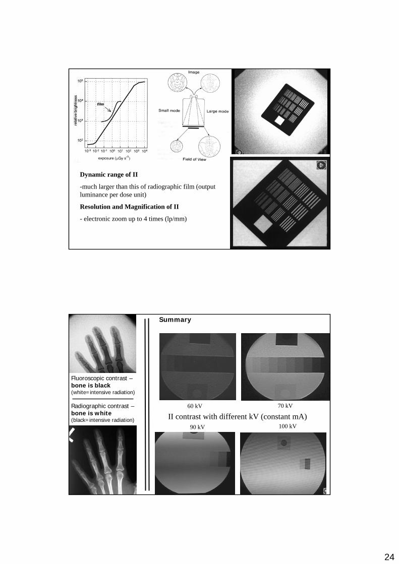
Dynamic range of II
-much larger than this of radiographic film (output luminance per dose unit)
Resolution and Magnification of II
- electronic zoom up to 4 times (lp/mm)
60 kV 70 kV
90 kV 100 kVII contrast with different kV (constant mA)
Radiographic contrast –bone is white(black=intensive radiation)
Fluoroscopic contrast –bone is black(white=intensive radiation)
Summary
Related Documents