.I T”W% 6 r409 X-551-70-449 THE UTILIZATION OF HALO ORBITS IN ADVANCED LUNAR OPERATIONS I / ROBERT W. FARQUHAR DECEMBER 1970 GODDARD SPACE FLIGHT CENTER GREENBELT, MARYLAND https://ntrs.nasa.gov/search.jsp?R=19710005876 2018-06-17T00:06:06+00:00Z

Welcome message from author
This document is posted to help you gain knowledge. Please leave a comment to let me know what you think about it! Share it to your friends and learn new things together.
Transcript

. I T ” W % 6 r409 X-551-70-449
THE UTILIZATION OF HALO ORBITS IN ADVANCED LUNAR OPERATIONS
I /
ROBERT W. FARQUHAR
DECEMBER 1970
GODDARD SPACE FLIGHT CENTER GREENBELT, MARYLAND
https://ntrs.nasa.gov/search.jsp?R=19710005876 2018-06-17T00:06:06+00:00Z

X-551- 70-449
THE UTILIZATION OF HALO ORBITS IN ADVANCED LUNAR OPERATIONS
BY
Robert W. Farquhar
December 1970
Goddard Space Flight Center Greenbelt, Maryland

CONTENTS
Page
1
. I . INTRODUCTION .................................
u
L'
I1 . MECHANICS OF HALO SATELLITES ................... 3
A . Motion in the Vicinity of the Translunar Libration Point ..... 3
3 5
1 . Equations of Motion ........................... 2 . Periodic Orbits ..............................
B . Orbit Control ................................. 5
1 . Stabilization ................................ 2 . Nominal Trajectories .......................... 5
6
a . Lissajous Path ............................ b . Halo Path ................................ 7
7
3 . Period Control .............................. 4 . Practical Stationkeeping Technique ................. 5 . Modification of Control Scheme for Electrical Propulsion . .
7 15 20
C . Transfer Trajectories ........................... 24
111 . LUNAR FAR-SIDE COMMUNICATIONS LINK ............. 29
A . Synchronous HALO Monitor (SHALOM) ................ B . Importance in Anticipated Unmanned Lunar Program ....... 29
30
1 . Support for Emplaced Stations and Roving Vehicles on Moon's Far Side ...................................
2 . Selenodesy Experiment ......................... 3 . International Cooperation .......................
30 30 32
C . Spacecraft Considerations ......................... D . Complete Lunar Communications Network .............. 35
37
IV . HALO ORBIT SPACE STATION IN SUPPORT OF AN EX- PANDED LUNAR EXPLORATION PROGRAM ............. 41
A . Elements of Expanded Lunar Program ................. 41
iii

CONTENTS-continued)
B . Role of Halo Orbit Space Station (HOSS) ................ 1 . Communications and Control Center ................ 2 . Lunar Logistics Depot ......................... 3. Comparison with Lunar Orbit Space Station (LOSS) Alter-
native .................................... C . Lunar Transportation System Performance .............
1 . Space Tug .................................. 2 . Nuclear Orbit-to-Orbit Shuttle (NOOS) ............... 3 . Chemical Orbit-to-Orbit Shuttle (COOS) .............. 4 . Final Comments .............................
D . Use of HOSS as a Launching Platform for Unmanned Planetary Probes ......................................
V . CONCLUSIONS AND RECOMMENDATIONS ............... REFERENCES ...................................... Appendix A . Nonlinear Equations of Motion .................. Appendix B . Analytical Solution for Lissajous Nominal Path ....... Appendix C . Fuel Cost for z-Axis Period Control .............. Appendix D . Derivation of Performance Function for a Two-Stage
Space Tug ................................ Appendix E . Derivation of Performance Function for a Two-Stage
Lunar Shuttle System ........................ Appendix F . Derivation of Performance Function for a Lunar Shuttle
System with a Two-Stage COOS .................
Page
42
42 44
45 Y
48
48 53 59 68
68
75
76
79 85 91
93
97
101 .
U
iv

L'
THE UTILIZATION OF HALO ORBITS IN ADVANCED LUNAR OPERATIONS
BY
Robert W. Farquhar
ABSTRACT
Flight mechanics and control problems associated with the stationing of space- craft in %a10 orbits" about the translunar libration point a re discussed in some detail. Practical procedures for the implementation of the control techniques a re described, and it is shown that these procedures can be carried out with very small AV costs.
The possibility of using a relay satellite in a halo orbit to obtain a continuous communications link between the Earth and the far side of the Moon is also dis- cussed. Several advantages of this type of lunar far-side data link over more conventional relay-satellite systems are cited. It is shown that, with a halo relay satellite, it would be possible to continuously control an unmanned lunar roving vehicle on the Moon's fa r side. Backside tracking of lunar orbiters could also be realized.
The desirability of locating a lunar space station in a halo orbit instead of a lunar polar orbit as recommended in the current NASA Tntegrated Program Plan" is investigated. It is found that the halo orbit location is superior in almost every respect. Of particular significance is the finding that the performance of a re- usable lunar shuttle transportation system using halo-orbit rendezvous is better than one using lunar-orbit rendezvous.
V

.)
‘8
LIST OF ABBREVIATIONS
SHALOM: Synchronous HALO Monitor
HOSS
Loss
PSD
00s
coos
NOOS
: Halo Orbit Space Station
: Lunar Orbit Space Station
: Propellant Storage Depot
: Orbit-to-Orbit Shuttle
: Chemical Orbit-to-Orbit Shuttle
: Nuclear Orbit-to-Orbit Shuttle
fps : feet per second
mPS : meters per second
n.mi. : nautical miles
V i i

THE UTILIZATION O F HALO ORBITS IN ADVANCED LUNAR OPERATIONS
.
3'
I. INTRODUCTION
The fact that the Moon always presents the same hemisphere towards the Earth both aids and hinders lunar exploration. Near-side lunar missions have been simplified because they have had direct access to at least one of the Earth-based control centers. However, far-side lunar operations will continue to be rather awkward until an uninterrupted communications link with the Earth is estab- lished. In 1966, an unusual relay-satellite scheme that would eliminate far-side communications blackout periods was presented (Ref. 1). With this technique, a single relay satellite that is forced to follow a so-called '!halo orbit" would provide continuous communications coverage for most of the Moon's far side. The halo-satellite relay concept is illustrated in Fig. 1. A comparison of this concept with another proposal that calls for two o r more relay satellites in a lunar polar orbit will be given in this paper.
In the initial planning phase for the Apollo Program, two rendezvous locations were considered. One was in Earth orbit and the other was in a low-altitude lunar orbit. As is well known, the lunar-orbit rendezvous mode was finally selected. Therefore, it is understandable that when the reusable lunar shuttle transportation system was first proposed, the lunar-orbit rendezvous technique was readily accepted. However, other rendezvous modes should receive some consideration before a final choice is made. In this paper, a new lunar shuttle mode that uses halo-orbit rendezvous will be investigated. The relative merits of the lunar-orbit and halo-orbit rendezvous concepts will be discussed at length.
Up to now, the usefulness of halo orbits has been overlooked in planning a future lunar exploration program. It is the purpose of this paper to exhibit the unique importance of halo orbits for both manned and unmanned lunar operations.
1

t ' \ RELAY SATELLITE
X
RELAY SATELLITE NASAGSFC-T&DS
MISSION 5 TRAJECTORY ANALYSIS DIVISION BRANCH 551 DATE 12/7/70 BY R W Farquhar PLOTNO 1353
~
4 = \ I RELAY SATELLITE
H A L O ORBIT A S SEEN FROM EARTH
Figure 1. Lunar Far-Side Communications with Halo Satellite
2

11. MECHANICS OF HALO SATELLITES
Before discussing the utility of halo satellites in future lunar operations, a brief description of the flight mechanics associated with the placement and mainte- nance of satellites in halo orbits is in order. Therefore, an overview of the orbit control techniques and the basic transfer trajectories for these satellites is presented here. To highlight the essential points, most mathematical details a re relegated to the appendices.
A. Motion in the Vicinity of the Translunar Libration Point
As shown by Lagrange in 1772, there are five points in the Earth-Moon gravita- tional field with the interesting property that if a satellite were placed at one of them with the proper velocity it would be in equilibrium because the gravitational accelerations acting on the satellite would be counterbalanced by its centripetal acceleration. These I1libration points" are all located in the Moon's orbital plane and their general configuration is depicted in Fig. 2. This paper will be pri- marily concerned with the translunar libration point, L,.
1. Equations of Motion
It should be noted at the outset that the distance between L, and the Moon is not constant. However, the ratio of this distance to the instantaneous Earth- Moon distance, R, is constant, that is
d2 7, = - = 0. 1678331476 R
Consider the motion of a satellite in the vicinity of the L 2 point. Using a Cartesian coordinate system (x, y, z) that is fixed at L,, it can be shown that the linearized equations of motion are* (Ref. 2)
.. x - 2 9 - (2B, t 1) x = 0 (2a)
*The usual normalizations are employed, i.e., the following quantities are taken a s unity: (1) un-
rad/sec); (3) sum of the masses of the Earth and the Moon perturbed mean Earth-Moon distance (a = 384,748.91 km); (2) mean angular rate of Moon around Earth (n = 2.661699489 x (M,/M, = 81.30).
3

MEAN DISTANCES
R -384,400 km d , = 58,000 km d, - 64,500 km
Figure 2. Libration Points in the Earth-Moon System
where B, = 3.19042. It is immediately obvious that the motion along the z-axis is independent of the motion in the xy-plane and is simple harmonic. The motion in the xy-plane is coupled and it can readily be shown (Ref. 2 ) that this motion possesses an oscillatory mode as well as a divergent one. Due to the presence of this divergent mode, a satellite will require some stationkeeping if it is to remain near the L, point.
Although Eq. (2) exhibits many of the principal features of motion in the vicinity of the L, point, it is an approximation that neglects the effects of nonlinearities, the eccentricity of the Moon's orbit, and the influence of the Sun's gi?avitational field.* To illustrate the complexity that is introduced by these effects, a more accurate set of equations is given in Appendix A.
*Solar radiation pressure could constitute another non-negligible effect i f the satellite had a large area-to-mass ratio.
4

2. Periodic Orbits
If certain initial conditions are satisfied, it is possible for a satellite to follow a periodic orbit about the libration point as shown in Fig. 2. These initial condi- tions are chosen so that only the oscillatory mode of the xy-motion is excited. However, the periodic orbit is unstable and stationkeeping is necessary for the satellite to remain in this orbit.
A whole family of these orbits exist and their equations a re given by
xn A x sin wxy t
(3 ) y, = A y c o s w t
XY
where w x y = 1.86265 and A = 0.343336 Ay. The period of these periodic orbits is about 14.67 days.
€3. Orbit Control
As noted above, the L, libration point and the periodic orbits around it a re in- herently unstable. Therefore, a satellite cannot remain in the vicinity of L, un- less it is equipped with a stationkeeping system (e.g., cold-gas jets). The ques- tion then arises, - since some stationkeeping is required in any case, why isn't it just as easy to station the satellite at some other fixed point in the Earth- Moon system? The answer is that the stationkeeping fuel cost is significantly higher in the vicinity of a non-equilibrium point. In theory, the fuel cost at a libration point can be made arbitrarily small. The same arguments hold for the periodic orbits around the libration points.
In this section, some of the details of a promising stationkeeping technique for a satellite in the vicinity of the L, point are presented. Additional controls that a r e needed to maintain satellites in halo orbits are also discussed.
1. Stabilization
An extremely simple control law has been devised to suppress the divergent mode of Eqs. (2a) and (2b). If the control acceleration, Fcx = -k,k - k2x, is added to the right-hand side of Eq. (2a), asymptotic stability is achieved pro- vided that k, > 0 and kz > (2B, + 1). This means that a satellite can remain at the L, point by using a control law that requires only range and range-rate measurements (Le., x and i). Moreover, the control acceleration is always directed along the same axis.
5
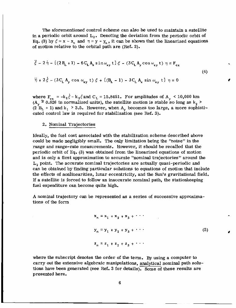
The aforementioned control scheme can also be used to maintain a satellite in a periodic orbit around L,. Denoting the deviation from the periodic orbit of Eq. (3) by 4 = x - x, and r] = y - yn , it can be shown that the linearized equations of motion relative to the orbital path are (Ref. 2).
2 - 2 - [ (2 B, t 1) - 6 CL A, s in wxy t 1 E - (3 C, AY c o s wx t ) r] = Fcx
(4) t 2 4 - (3C, Ay C O S wxy t ) 5 t [(% - 1) - 3C, A, sin wxy t I r ] = 0
where Fcx = -k14- k,Cand C, = 15.8451. For amplitudes of Ay < 10,000 km
(AY (2 B L + 1) and k, > 3.5. However, when % becomes too large, a more sophisti- cated control law is required for stabilization (see Ref. 3).
0.026 in normalized units), the satellite motion is stable so long as k, >
2. Nominal Trajectories
Ideally, the fuel cost associated with the stabilization scheme described above could be made negligibly small. The only limitation being the ?'noise?' in the range and range-rate measurements. However, it should be recalled that the periodic orbit of Eq. (3) was obtained from the linearized equations of motion and is only a first approximation to accurate "nominal trajectories'? around the L, point. The accurate nominal trajectories are actually quasi-periodic and can be obtained by finding particular solutions to equations of motion that include the effects of nodinearities, lunar eccentricity, and the Sun's gravitational field. If a satellite is forced to follow an inaccurate nominal path, the stationkeeping fuel expenditure can become quite high.
A nominal trajectory can be represented as a series of successive approxima- tions of the form
xn = x l t x , + x 3 + -
Y, =Y, t Y , t Y 3 t * *
z, = 2, + z2 t z3 t ' *
(5)
where the subscript denotes the order of the term. By using a computer to carry out the extensive algebraic manipulations, analytical nominal path solu- tions have been generated (see Ref. 3 for details). Some of these results are presented here.
6

a. Lissaious Path
The third-order solution for the nominal path in the vicinity of L, is given in Appendix B. Traces of this solution for a one-year period are shown in Figs. 3 and 4. Because the period of the oscillatory motion in the Moon's orbital plane is 14.65 days while the out-of-plane period is 15.23 days, the yz-projec- tion of the nominal path is a Lissajous curve.
The effect of the accuracy of the nominal path on the stationkeeping fuel con- sumption has been tested with a computer simulation. For A,, = A, = 3500 km, the average stationkeeping costs were:
first-order nominal path: 1876 fps/yr (571.8 mps/yr) second-order nominal path: 314 fps/yr (95.7 mps/yr) third-order nominal path: 77 fps/yr (23.5 mps/yr)
These results dramatically illustrate the importance of an accurate nominal path.
b. Halo Path
For every value of AY >32,871 km, will produce a nominal path where
there is a corresponding value of A, that the fundamental periods of the y-axis and
z-axis oscillations are equal. In this case, the nominal path as seen from the Earth will never pass behind the Moon. The exact relationship between A, and A, for this family of nominal paths is given in Fig. 5.
It should be noted that the Lissajous nominal path solution of Appendix B is no longer valid in this instance, and a new solution is required. The task of gen- erating this halo nominal path has been completed (see Ref. 3), and traces for a typical trajectory for a one-year period a re depicted in Figs. 6-8. Due to the large amplitudes of A, and A,, the effects of the nonlinearities are quite pronounced. However, notice that the differences between the second and third-order solutions are barely distinguishable.
3. Period Control
For many applications a small amplitude satellite trajectory about L, is pre- ferred. Unfortunately, the nominal trajectory for this case is a Lissajous path that will occasionally be hidden from the Earth as shown in Fig. 9.* However,
*When the satellite i s outside of the occulted zone, it will be visible from any point on the Earth facing the Moon.
7

NASA.GSFC T&DS MISSION &TRAJECTORY ANALYSIS DIVISION BRANCH 551 DATE 12/7/70 BY R W F2,quhar PLOTNO 1352
~
First- Order
Second Order Third Order
Figure 3. Lissaious Nominal Trajectory (Projection in Moon's Orbital Plane) Grid Size i s 1290 km.
8

I I I t ' I I I I
First -Order
NASA-GSFC-T&OS MISSION &TRAJECTORY ANALYSIS DIVISION BRANCH 551 O A T E L BY R.W F a q u h a PLOTNO. 1353
Second Order Third Order
Figure 4. Lissajous Nominal Trajectory- (Projection in Plane Perpendicular to Earth-Moon Line). Grid Size i s 1290 km.
9

10

First Order NASA-GSFC-T&DS
MISSION 5 TRAJECTORY ANALYSIS DIVISION BRANCH 551 DATE 1217170 BY R W Farquhar PLOTNO. 1355
Second Order Third Order
Figure 6. Halo Nominal Trajectory (Projection in Moon's Orbital Plane) Grid Size i s 12,900 km.
11

First Order
Third Order Second Order
Figure 7. Halo Nominal Trajectory (Projection in Plane Perpendicular to Earth-Moon Line). Grid Size i s 12,900 km.
NASA GSFC-T&OS MISSION &TRAJECTORY ANALYSIS DIVISION BRANCH 551 DATE 12/7/70 BY R.W. Farquhar PLOT NO 1356
12

NASA-GSFC-T&DS Projection in Moon’s Orbital Plane MlsslON&TRAJECTORv ANALYsIsDlV lS lON BRANCH 551 DATE 12/7/70 BY R W Farquhar PLOTNO 1357
Projection in Plane Perpendicular to Moon’s Orbital Plane
Figure 8. Halo Nominal Trajectory Relative to Mean L, Point. Grid Size is 12,900 krn.
13

NASA GSFC T&DS MISSION & TRAJECTORY ANALYSIS DIVISION BRANCH 551 DATE 1217170 BY R W Farquhar PLOT N O 1358
Figure 9. Nominal Trajectory A s Seen From Earth. (Without Period Control.)
Grid Size i s 1290 km.
it is possible to use thrust control to alter the period of the z-axis oscillation so that it will be synchronized with the y-axis period. When this is done, the nominal path is transformed into a halo orbit as illustrated in Fig. 10.
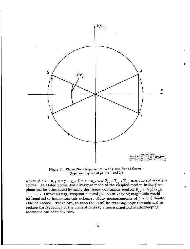
A simple control scheme to bring about this synchronization is to apply a thrust impulse along the z-axis every 7.32 days (Ref. 4). The phase plane representa- tion of this technique is given in Fig. 11. Although the main idea is diagramed in Fig. 11, it should be noted that the control logic is somewhat more compli- cated in actual practice (see Ref. 3).
For operational reasons, it may be desirable to impart the period control pulses less frequently than every 7.32 days. In this case, the amplitude of the halo orbit, A,, must be increased to insure nonoccultation because the satellite will follow a Lissajous nominal path between impulses. Higher-order nominal path corrections will cause an additional enlargement of AH. These increases in AH will in turn cause the average cost for the period control, FC, to increase. The dependence of A, and E on the interval between control pulses, A t , is
14

tz I
NASA-GSFC TBDS MISSION &TRAJECTORY ANALYSIS DIVISION BRANCH 551 DATE 12/7/10 BY R W Farquhar PLOTNO 1359
~
Figure 10. Nominal Trajectory As Seen From Earth. (With Period Control For 1 Year.) Grid Size i s 1290 km. Using Sinusoidal z-Axis Control (see Ref. 2).
is shown in Figs. 12 and 13.* A brief derivation of the relationships between A,, 5 , and A t is presented in Appendix C.
4. Practical Stationkeeping Technique
For a controlled satellite that is following a small-amplitude nominal path, the linearized equations of motion relative to the nominal path are approximately
CY 7 t 2 i + (q- 1) = F
5 t BL 5 = FCZ
*Although continuous curves are shown, only the discrete values at At =7.32, 14.65, etc. are meaningful.
15
NASA GSFC TBDS MISSION (L TRAJECTORY ANALYSIS DIVISION BRANCH 551 DATE 12/7/70 8 Y R W F - W ~ W PLOTNO 1360
Figure 11. Phase Plane Representation of z-axis Period Control. (Impulses applied at points 1 and 3.)
where t = x - x n , q = y - y n , 5 = z - z n , a n d F C x , Fcy , F,, are control acceler- ations. As stated above, the divergent mode of the coupled motion in the r ) - plane can be eliminated by using the linear continuous control FCx = -k ,E-k 2c, F bg’required to implement this scheme. Many measurements of and would also be needed. Therefore, to ease the satellite tracking requirements and to reduce the frequency of the control pulses, a more practical stationkeeping technique has been devised.
= 0. Unfortunately, frequent control pulses of varying magnitude would
16

.
'd
0 0 0 0 E Q 8 m
0 0 0 0 0 0 h '0 rr)
(VI H V
17

In Ref. 3, the following stationkeeping procedure is proposed:
(1) Track the satellite for an interval (an hour may be adequate) sometime before and after each control pulse to obtain estimates for 4 , & , and 77. (The time between pulses is typically 2 to 4 days.)
(2) For some constant value, F, , compute the time, ti , that either F Z F o r F 5 - F, where F = + A e - k q (A and k a re constants).
(3) Apply a thrust impulse at time ti. If F 1 F,, the impulse is directed along the negative e-axis. If F 5 - F, , the impulse is directed along the positive &axis. All control impulses a re equal in magnitude. (Stability is achieved by allowing the time interval between impulses to vary).
Use of the method outlined above will cause the satellite to follow a limit-cycle motion in the neighborhood of the L, point. With the proper choice of F1 and the impulse magnitude, A t , the satellite will be captured in a "one-sided" limit cycle as shown in Fig. 14. Two-sided limit cycles are also possible, but are usually not desired because the fuel costs are higher.
The average stationkeeping cost for a one-sided limit cycle with Jmin = 15 km is given in Fig. 15." In theory, this cost could be lowered by choosing a smaller value for emin. However, in actual practice the optimum value of Cmin is a function of the accuracies of the nominal path solution and of the estimates for g, e , and 7 . Preliminary results from a digital computer simulation of the limit- cycle motion when nonlinear and time-varying effects a re included in the equa- tion of motion (see Appendix A) indicate that the satellite will spend most of its time in one-sided limit cycles when Emin 1 15 km.
The control parameters A and k that are contained in the switching function, F = 8 + A t - kq, a re determined from stability and response considerations. In Fig. 16, the damping effect of the parameter k on the transient response is il- lustrated. Notice that the stability of the one-sided limit cycle is jeopardized when k becomes too large.
The important constant F, is given byt
*The nominal time interval between control pulses refers to a steady-state condition. t T h e derivation of this formula and other theoretical results relating to the stationkeeping tech-
nique that i s described in this section can be found in Ref. 3.
18

( JX / sdw )
0. - b. 2 'u, N
0 0 N 8O m 8 * 8 0 0 0 0 h * Ir)
(J+dj) ,,, 19

5 min
CONTROL PULSE
NASA-GSFC T5DS MISSION 5 TRAJECTORY ANALYSIS DIVISION BRANCH 551 DATE 12/7/10 BY R W Farquhar PLOTNO 1363
Figure 14. One-sided Limit Cycles (Steady-State Condition).
Graphs of the dependence of A t and Q on the nominal limit-cycle period a re shown in Figs. 17 and 18.
5. Modification of Control Scheme for Electrical Propulsion
For various reasons, it may be desirable to use an electrical propulsion device to control a halo satellite. However, because these devices normally operate at very low thrust levels, long periods of thrusting would be required. Therefore, the impulsive control techniques described above could not be applied without some modification.
One way to modify the impulsive controls is to simply replace the impulses with finite constant-thrust periods. When the impulsive period control is SO altered, its phase-plane representation is changed to the form shown in Fig. 19 (cf. with Fig. 11). It can be shown that the magnitude of the constant thrust acceleration for this case is (see Ref. 3 for derivation).
FcZ = A, a:
20

0- 8
z >- v d v) w WJ -1 3
-1 0 II? t- Z 0 W Z W W
a
F W
-1 Q: > IY w I-
m
z W I I- -1 4 Z I 0 Z
-
-
21

c
II Y
0 II Y
22
m It Y
hl It Y 4 '
- F =
I' I

23

Q
NASA GSFC T&OS NOMINAL TIME INTERVAL BETWE EN CONTROL PULSES (DAYS) MISSION & T R A ~ E C T O R Y ANALYSIS DIVISION BRANCH 551 DATE 12\7/70 BY R W Farquhar PLOTNO 1566
Figure 18. Q Vs. Nominal Limit-Cycle Period.
where w X y = 1.865485, W , = 1.794291, E = 0.0736493, and the fraction of time that the engine is turned on is 2 +/n . If A, = 3500 km and = n/3, Eq. (8) gives F,, = 6.04 x lo-’ g.* For an analysis of the stationkeeping technique when the impulses are replaced by constant-thrust periods, see Ref. 5.
C. Transfer Trajectories
In this section, the A V requirements for some transfer trajectories between an Earth parking orbit and the vicinity of the L, point are presented. The results
*It i s useful to know that 1 fps/yr 2 1 x g.
24

NASA GSFC T&DS MISSION 5 TRAJECTORY ANALYSIS DIVISION BRANCH 551 DATE 1217170 BY R W Filquhar PLDTNO 1367
Figure 19. Phase Plane Representation of z-axis Period Control. (Continuous Thrusting Between Points 1 -, 2 and 3 -4).
given here were obtained by employing a restricted three-body model and numerically integrating the equations of motion. Only trajectories which lie in the Moon's orbital plane have been considered. Although the A V requirements were calculated for trajectories terminating at L,, they closely approximate the corresponding values for transfers to small-amplitude halo orbits around
2-
25

A typical 2-impulse trajectory between the Earth parking orbit and L, is de- picted in Fig. 20. The variation in A V as a function of the transfer time for this mode is given in Fig. 21. Notice that the A V curve for the impulse at L, is starting to flatten out at t = 108 hrs. Thus, it appears that very little savings can be realized by extending the transfer time beyond 108 hrs.
Fortunately, it is possible to sharply reduce the 2-impulse A V costs by using a powered lunar swingby (Ref. 4). This transfer mode uses 3 impulses and is illustrated in Fig. 22. The total transfer time for this mode is almost 9 days, but the reduction in A V is appreciable.
Trajectories that start at L, and terminate in the Earth parking orbit are just mirror images of the trajectories shown in Figs. 21 and 22. The A V costs for the corresponding inbound and outbound transfers are identical.
TRANSFER TIME 96 HRS
A\' REQUIREMENTS EARTH. 10,333 fpr (3149.5 "p) MISSION L TRAJECTORY ANALYSIS DIVISION NASA GSFC TLDS
L,: 4035 fps (1229.9 "p) BRANCH 551 DATE 12/1/10 BY R . W . F ~ U ~ W PLOTNO 1358
Figure 20. Two-Impulse Transfer From 100 n.mi. (185.2 km). Earth Parking Orbit to L, Point.
26

Y
TRANSFER
Figure 21. A V Cost For Two-Impulse Transfer From 100 n m i . (185.2 km) Earth Parking Orbit to L, Point.
27

28
c C
0 .- a cy A 0 t t .- -E 0 0) C .- : a
. .
00
E .- 0,- In
e : U-2
.
I

III. LUNAR FAR-SIDE COMMUNICATIONS LINK
Due to the lack of a far-side communications capability, lunar surface explora- tion (manned and unmanned) has been limited to the Moon's near side. To re- ceive maximum scientific return from the costly spacecraft that have been developed for lunar exploration, this undesirable restriction should be removed. The role of halo satellites in eliminating the lunar far-side communications constraint is treated in this section.
A. Synchronous HALO Monitor (SHALOM)
The main geometrical features of the halo satellite method for establishing an uninterrupted lunar far-side communications link are illustrated in Figs. 1 and 23. By using the control techniques given in Section II-B, the relay satellite could remain in the halo orbit where it would always be visible from both the Earth and the far side of the Moon. Because it has properties that are similar to synchronous satellites of the Earth (24-hour satellites), the halo communica- tions satellite might well be termed a Synchronous HALO Monitor (SHALOM). The quasi-stationary characteristic of SHALOM* greatly simplifies the acquisi- tion and tracking problems for an antenna on the Moon's far side. As a matter of fact, a halo orbit with a radius of 3500 km would always lie within the 11.1" beamwidth of a fixed lunar surface antenna even when the latitudinal and longi- tudinal oscillations of the Moon? are taken into account.
MISSION 5 TRAJECTORY ANALYSIS DIVISION BRANCH 551 DATE 12/1/70 S Y L W Farquhar PLOT NO 1371
H A L O ORBIT NASA GSFC T&DS
4 JPLANE 18.87'
EARTH MOON
I I REUY SATELLITE'
Figure 23. Halo Satellite Geometry (not to scale).
*The relay satellite would take about 2 weeks to complete one circuit of the halo path. ?The latitudinal oscillation is about rt6.73O and the longitudinal oscillation i s approximately
9.75' . These oscillations are usually called 'lunar librations."
29
Another scheme for providing lunar far-side communications coverage would use two o r more relay satellites in a lunar polar orbit (Refs. 6-8). This method would have shorter communications distances than the halo satellite technique, but would be less attractive in other respects. Some of the advantages of SHALOM over the polar-orbiting satellite system are summarized in Table 1.
B. Importance in Anticipated Unmanned Lunar Program
The curtailment of the Apollo Program and the ensuing gap in manned lunar exploration has created a need for an automated lunar program. To supplement Apollo results, these unmanned missions should gather data from the entire lunar surface, particularly sites that are considered to be too risky for manned landings (e.g., the Moon's far side). Clearly, SHALOM will be a key element in this program.
1. Support for Emplaced Stations and Roving Vehicles on Moon's Far Side
A widely-spaced network of emplaced scientific stations on the Moon is needed to answer many of the fundamental questions concerning the structure and composition of the lunar interior. The acquisition of seismic data would have the highest priority, but other geophysical observations (e.g., measurements from strainmeters, triaxial magnetometers, and heat flow experiments) would also be enhanced by obtaining global measurements. When the network measure- ments are augmented with data collected from automated rovers and lunar orbiters, a fairly complete geophysical picture of the Moon should emerge.
A halo comsat could support the stations and rovers on the far side of the Moon. The continuous communications capability would be of great value since even small gaps in the data would seriously degrade some of the geophysical experi- ments. This continuous communications link would also be needed for remote control of lunar rovers. A summary of these services and other supporting functions of SHALOM is given in Table 2.
2. Selenodesy Experiment
A more accurate determination of the gravitational field of the Moon would be of value to future manned lunar missions as well as lunar science. One method for gaining this improvement would be to obtain accurate Doppler tracking measurements of a low-altitude polar orbiter from the front and back sides of the Moon. The back-side tracking data would, of course, be collected from SHALOM. For additional selenodesy payoff, the polar orbiter should carry a radar altimeter and a gravity gradient measuring instrument.
30

.
k
h
m
3 1
2 43 P-
rn a w 0 0 43 rl
31

Table 2 Lunar Far-Side Mission Support Tasks For Halo Communications Satellite
1. Relay of spacecraft telemetry data to Earth and command signals to space- craft during lunar landing and take-off operations.
2. Continuous monitoring of scientific data from emplaced stations on Moon's far side.
3. Transmission of television from roving vehicle to Earth-based control center. Control commands from Earth are relayed to rover.
4. Tracking of lunar orbiters when they are hidden from Earth stations.
5. Provide a real-time, two-way communications link between Earth stations and a manned spacecraft that is occulted by the Moon.
3. International Cooperation
I
The early development of a halo relay satellite would offer an uncommon op- portunity for a joint Soviet-American lunar mission. Although the Soviets a re engaged in an extensive lunar exploration program (Ref. 9), they do not as yet appear to have plans for a far-side communications satellite. With an American halo comsat and a Russian sample-return vehicle (such as Luna-16) o r surface rover (such a s Luna-l7), the first far-side landing could become a reality.
A s a possible landing site for a far-side mission, consider the crater Tsiolkovsky (see Figs. 24-27). This crater is one of the most spectacular features on the far side of the Moon and has been studied in great detail (e.g., see Ref. 10). The exceptionally smooth crater floor of Tsiolkovsky (see Fig. 27) is ideally suited for automated landings and long-range traverses of roving vehicles.
Some of the noteworthy features of this type of cooperative space project are:
1. Hardware interface problems would be minimal.
2. Military and commercial space interests would not be involved.
3. Both nations would have a part in the first landing on the Moon's far side.
4. The lunar far-side communications capability could be shared with other nations in addition to the Soviet Union.
32

33
Figure 24. The Southwestern Area of the Moon's Far Side. Tsiolkovsky is the Conspicuous Dark-Floored Crater. (Lunar Orbiter Photo). Framelet Width is 55 km.


.
- -___.__- "_
Figure 26. The Central Peak of the Tsiolkovsky Crater (Apollo-8 Photo).
C. Spacecraft Considerations
A number of preliminary design studies of halo communications satellites have already been completed (Refs. 4, 11, and 12). The findings of these studies to- gether with the orbit control results of Section II-B provide a basis for estimat- ing overall spacecraft weight and launch vehicle requirements. Some pertinent data for a typical halo spacecraft is given in Table 3.
To gain some feeling for the communications performance of the halo comsat, a link calculation for television signals from a lunar surface rover to the relay satellite is presented in Table 4. This particular link was chosen for this cal- culation because it is the most stringent requirement for the communications system.
35

Figure 27. Close-up View of the Western Half of Tsiolkovsky. Most of the Crater’s Floor Has Been Flooded by a DarkMaterial whose Freshness is indicated by the Absence of Large Craters and the Sparse Distribution of Small Ones. [Lunar Orbiter Photo.) Framelet Width is 7 km.
36

Table 3 Preliminary Spacecraft Design Data for SHALOM
Operational Lifetime
Radius of Halo Orbit
Launch Vehicle
Spacecraft Weight (at Translunar Injection)
AV Requirements
Midcourse Corrections Halo Injection Stationkeeping (1 pulse every 3 days) Period Control (1 pulse every 7.32 days) Attitude Control
Total
Fuel Weight
3 years
3500 km
TAT^ C)/DE LTA/ TE 364
900 lb. (408.2 kg.)
(fPS)
100 1100
280 1020
75
2575
264 lb.
(mps)
30.48 335.28
85.34 310.90
22.86
784.86
( 1 19.7 kg , - . (Hydrazine Isp = 230 sec.)
D. Complete Lunar Communications Network
If the radius of the halo orbit were enlarged to about 3700 km, it would always be in view from the L, point (see Fig. 2) as well as the Earth. Therefore, by sta- tioning a second relay satellite at L, , a point-to-point communications system covering most of the lunar surface could be established. (This system was originally proposed in Ref. 13). However, this two-satellite system would not provide adequate coverage for the Moon's polar and limb regions. Since these particular regions a re of high scientific interest (especially Mare Orientale on the western limb), dependable communications support should be made available.
To provide coverage for the poles and limbs while still retaining many of the desirable features of SHALOM, a very large halo orbit is employed (see Figs. 6-8). Three relay satellites are spaced at 4.85-day intervals in this orbit as shown in Fig. 28. Because the nominal trajectory for the relay satellite net- work is shifted upward along the z-axis, coverage is poorest for the south polar region. Approximate maximum and minimum values of the relay-satellite
37
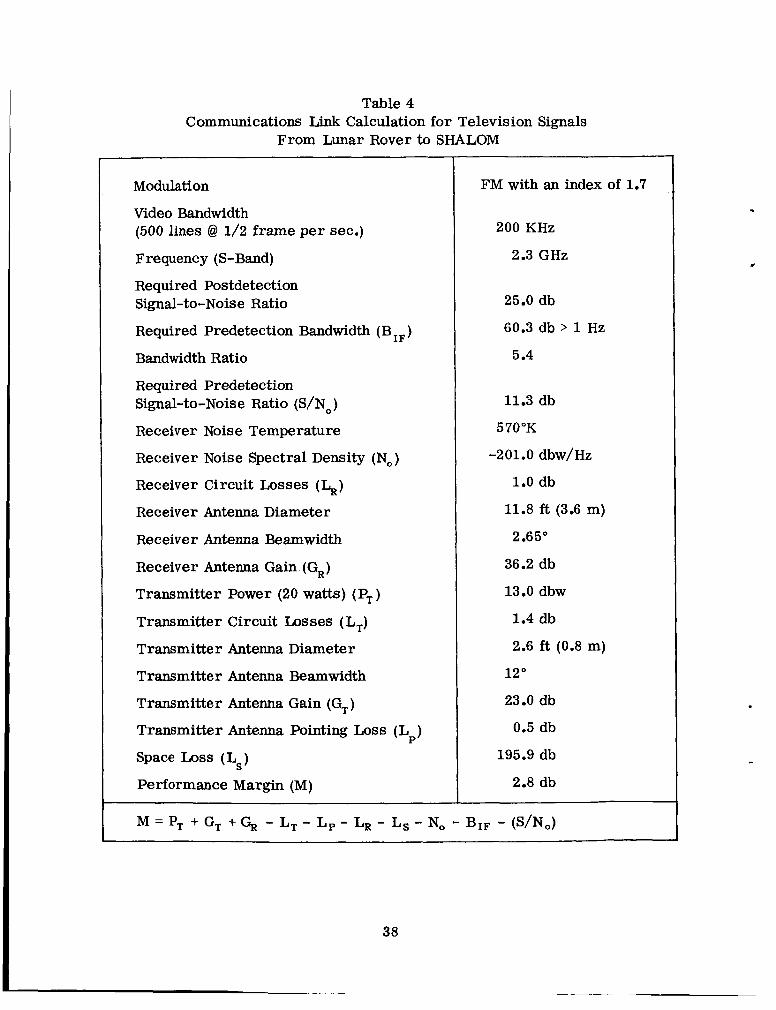
Table 4 Communications Link Calculation for Television Signals
From Lunar Rover to SHALOM
Modulation
Video Bandwidth (500 lines @ 1/2 frame per sec.)
Frequency (S-Band)
Required Postdetection Signal-to-Noise Ratio
Required Predetection Bandwidth (B IF)
Bandwidth Ratio
Required Predetection Signal-to-Noise Ratio (S/No)
Receiver Noise Temperature
Receiver Noise Spectral Density (No)
Receiver Circuit Losses (h) Receiver Antenna Diameter
Receiver Antenna Beamwidth
Receiver Antenna Gain (G,)
Transmitter Power (20 watts) (P,)
Transmitter Circuit Losses ( L,) Transmitter Antenna Diameter
Transmitter Antenna Beamwidth
Transmitter Antenna Gain (G,)
Transmitter Antenna Pointing Loss ( Lp)
Space Loss (Ls)
Performance Margin (M)
FM with an index of 1.7
200 KHz
2.3 GHz
25.0 db
60.3 db > 1 Hz
5.4
11.3 db
570°K
-201.0 dbw/Hz
1.0 db
11.8 ft (3.6 m)
2.65"
36.2 db
13.0 dbw
1.4 db
2.6 ft (0.8 m)
12 "
23.0 db
0.5 db
195.9 db
2.8 db
38

.
AS SEEN FROM MOON
8 .
I
I . PROJECTION IN RANE
PERF'ENDICUP.2 TO MOON'S ORBITAL RANE PROJECTION IN MOON'S ORBITAL PLANE
NASA GSFC T&DS MISSION & TRAJECTORY ANALYSIS DIVISION BRANCH 551 DATE 12/7/70 BY R W . F a q u h a r PLOTNO 1372
Figure 28. Typical Halo Trajectory Segment for Relay Satellite Network (Relative to Mean L, Point). Grid size i s 12,900 km. Relay Satellites are Located at @ and @ (Network i s shown at Time of Minimum Coverage For South Polar Region).
Time interval between Tick Marks is 6 hours.
39

Table 5 Approximate Relay-Satellite Elevation Angles with
Lunar Librations Taken into Account
Station Location
North Pole
South Pole
Limb
Favorable Libration Unfavorable Libration
Maximum Minimum Maximum Minimum Elevation Angle Elevation Angle Elevation Angle Elevation Angle
30" 22" 14" 7"
34" 11" 18" - 4"
39" 30" 25" 16"
elevation angles from different lunar sites are given in Table 5. Notice that there would be infrequent periods when none of the three relay satellites would be visible from the south pole. However, if required, this deficiency could be eliminated by using a four-satellite network.*
A final point concerning the potential utility of the three-satellite communications network: - it may also be very useful as a navigation aid for vehicles on the Moon's far side. This service would be most important when real-time data is required (e.g., during lunar landing operations).
* I t may also be possible to communicate directly with an Earth station during these periods.
40

.
I -
IV. HALO ORBIT SPACE STATION IN SUPPORT OF AN EXPANDED LUNAR EXPLORATION PROGRAM
In the Summer of 1969, the Presidents' Space Task Group proposed a compre- hensive "Integrated Program Plan" for lunar exploration in the 1980's and be- yond (Ref. 14). A key item in this plan is the establishment of a space station in the vicinity of the Moon. The Integrated Program Plan specifies that this space station be placed in a 60 n.mi. (111.12 km) polar lunar orbit. It is the purpose of this section to demonstrate that it would be better to locate the lunar space station in a halo orbit around the translunar libration point.*
A. Elements of Expanded Lunar Program
In order to achieve the goals and objectives of an expanded lunar exploration program, it will be necessary to increase the limited landing-site accessibility, staytime, payload and mobility capabilities of the Apollo program. The fre- quency of lunar missions will also be increased. The final phase of this strategy calls for the creation of a permanent or semi-permanent lunar surface base. To accomplish a lunar program of this magnitude at a reasonable cost, it appears that a fully reusable Earth-Moon transportation system should be developed. The principal hardware elements of the Earth-Moon transportation system would be:
1. Nuclear orbit-to-orbit shuttle (NOOS) o r chemical orbit-to-orbit shuttle (COOS): A reusable vehicle that operates between Earth orbit and the halo orbit. (See Refs. 16-18 for a description of the nuclear shuttle vehicle .)
2. Halo orbit space station (HOSS): A small manned station that is located in a 3500-km halo orbit about L,.
3. Propellant storage depot (PSD): An unmanned facility that is stationed near the HOSS. (A preliminary design is described in Ref. 19.)
4. Space Tug (Ref. 20): A reusable chemical vehicle that operates between the HOSS and the lunar surface.
In a typical mission sequence, the orbit-to-orbit shuttle (00s) will be used to transport personnel and cargo from an Earth-orbital base to the H0SS.t The
"It i s interesting to note that libration-point spacestations supporting lunar surface operations were
?As in the Integrated Program Plan, another reusable shuttle vehicle that performs transfers between discussed by Arthur C. Clarke as early as 1961 (Ref. 15).
Earth and Earth orbit i s used to replenish the Earth-orbital base.
41

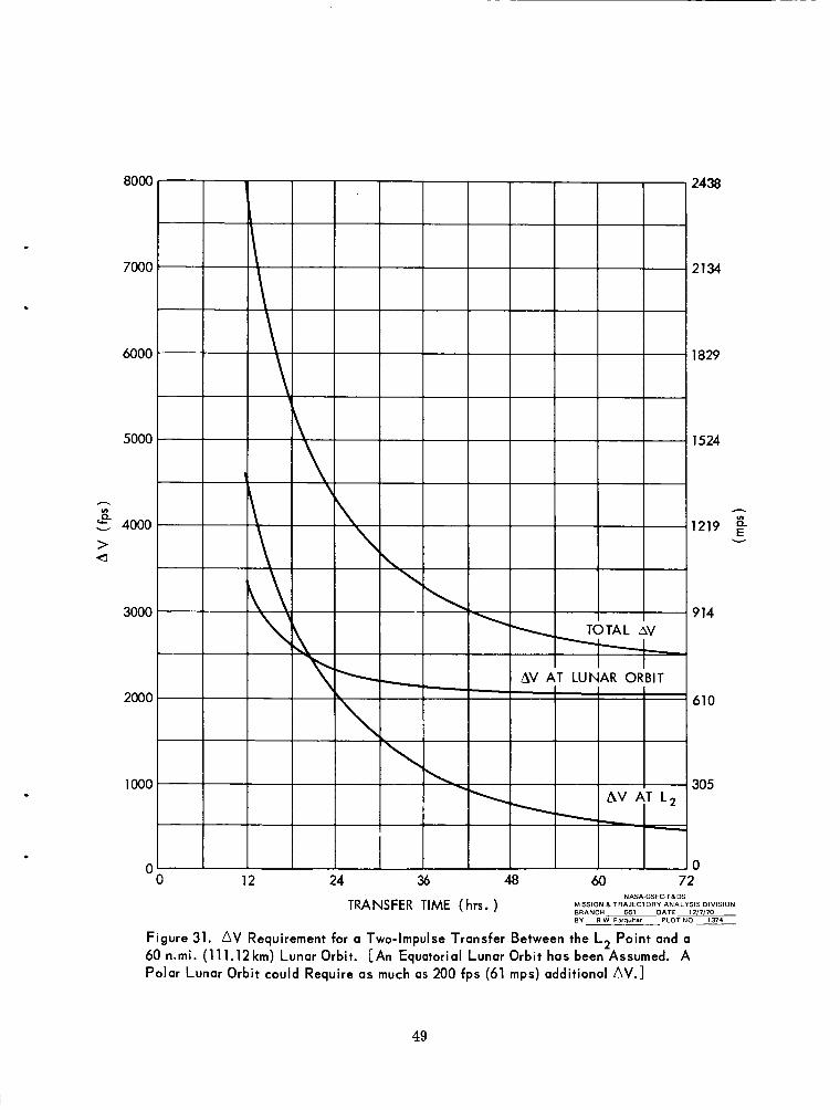
00s will follow a 3-impdse trajectory such as the one illustrated in Fig. 22. Upon arrival at the halo orbit, the men and supplies will be transferred to the HOSS and the propellant for the lunar Space Tugs will be stowed in the PSD. The 00s will then return to the Earth orbit. Transfer of cargo and passengers to the lunar surface will be effected by the Space Tug. Typical trajectories be- tween the HOSS and a 60 n.mi. (111.12 km) lunar orbit are shown in Fig. 29.*
B. Role of Halo Orbit Space Station (HOSS)
The primary task for a lunar space station is to provide operational support for all lunar surface and orbital activities. Some of these support functions a re discussed below.
1. Communications and Control Center
A halo orbit is an ideal location for a lunar communications and control center. This is so because continuous communications coverage for all far-side lunar operations would be available directly from the HOSS without dependence on relay satellites. Uninterrupted direct contact between the HOSS and the Earth is also maintained. Moreover, by placing relay satellites at the L, point and in a large halo orbit as shown in Fig. 28, the HOSS will always be able to communi- cate with any point on the Moon or in orbit about it! tions and control network has the added advantage of being quasi-stationary with respect to the lunar surface. Finally, it should be noted that direct coverage of near-side lunar operations is already obtainable from Earth stations.
This type of communica-
The continuous communications coverage of the lunar far side by the HOSS will be especially beneficial when a lunar astronomical observatory is established since it is quite likely that this observatory will be located on the far side of the Moon. In the 1967 Summer Study of Lunar Science and Exploration (Ref. 21), the Astronomy Working Group recommended a near-equatorial far-side observa- tory site. The Astronomy Working Group also stated a preference for a crater with a diameter of approximately 100 km and a rim height greater than 1 km above a fairly flat crater floor. An area of about 30 by 60 km that is free of cliffs, mountains, canyons, etc. is also desired for radio astronomy. It appears that the criteria listed above are nicely satisfied at the crater Tsiolkovsky (Figs. 24-27).
A summary of some of the most important communications and control functions of the HOSS is presented in Table 6 . Routine functions such as monitoring of
*As previously mentioned in Section 11-C, for trajectory calculations the halo orbit terminus is
tThe radius of the halo orbit for the space station must be at least 3700 km to maintain contact well approximated by the L, point.
with the relay satellite at L,.
42

t d
t d N -
ii E
m
P
43
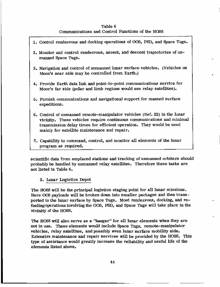
Table 6 Communications and Control Functions of the HOSS
1. Control rendezvous and docking operations of OOS, PSD, and Space Tugs.
2. Monitor and control rendezvous, ascent, and descent trajectories of un- manned Space Tugs.
3. Navigation and control of unmanned lunar surface vehicles. (Vehicles on Moon's near side may be controlled from Earth.)
4. Provide Earth data link and point-to-point communications service for Moon's far side (polar and limb regions would use relay satellites).
5. Furnish communications and navigational support for manned surface expeditions.
6. Control of unmanned remote-manipulator vehicles (Ref. 22) in the lunar vicinity. These vehicles require continuous communications and minimal transmission delay times for efficient operation. They would be used mainly for satellite maintenance and repair.
7. Capability to command, control, and monitor all elements of the lunar program as required.
scientific data from emplaced stations and tracking of unmanned orbiters should probably be handled by unmanned relay satellites. Therefore these tasks are not l is ted in Table 6.
2. Lunar Logistics Depot
The HOSS wil l be the principal logistics staging point for all lunar missions. Here 0 0 s payloads will be broken down into smaller packages and then trans- ported to the lunar surface by Space Tugs. Most rendezvous, docking, and re- fuelingoperations involving the OOS, PSD, and Space Tugs will take place in the vicinity of the HOSS.
The HOSS will also serve as a %angarl' for all lunar elements when they are not in use. These elements would include Space Tugs, remote-manipulator vehicles, relay satellites, and possibly even lunar surface mobility aids. Extensive maintenance and repair services wil l be provided by the HOSS. This type of assistance would greatly increase the reliability and useful life of the elements listed above.
44

There are two inherent advantages associated with the halo orbit location for the logistics staging point. They are:
1. The quasi-stationary characteristic of the halo orbit with respect to the Earth-Moon line and the lunar surface permits considerable flexibility in the scheduling of lunar shuttle operations. For instance, the launch window for transfers between the halo orbit and the lunar surface is infinite.
2. The A V requirements for transfers between the halo orbit and the lunar surface are almost identical for any landing site since plane changes can be made quite cheaply at the halo orbit. The difference in AV cost is usually less than 200 fps (61 mps).
3. Comparison with Lunar Orbit Space Station (LOSS) Alternative
Current versions of the Integrated Program Plan advocate a 60 n.mi. (111.12 km) polar lunar orbit for the lunar space station. The rationale for the selection of a polar inclination for the LOSS seems to be that a polar LOSS would pass over the entire lunar surface very 14 days.* Although the use of a polar orbit would permit Space Tug landings at any point on the Moon with little or no plane change, the nominal surface staytime would probably be constrained to 14-day intervals. Otherwise, a plane change would be required when the tug returns to the LOSS. The A V penalty for this plane change as a function of surface staytime is given in Fig. 30 (from Ref. 23). It should be noted that the results in Fig. 30 were obtained by using a near-optimal three-impulse transferJ
The selection of a low-altitude orbit for the LOSS has evidently been motivated by a desire to carry out an extensive program of orbital science (e.g., surface mapping, particles and fields experiments) from the LOSS. However, this reas- oning is highly questionable. A recent study (Ref. 24) of the scientific uses of a lunar orbital base has concluded that:
Y3cientifically, there is no strong justification for a lunar orbital base, and that such a base should not be established unless there are compell- ing non-scientific reasons for doing so. . . The orbital science, except for photography, can be performed as well, or better, from an unmanned, non-returning spacecraft.?l
*The orbit plane for the lunar polar orbit i s essentially fixed in inertial space with the Moon's rotation accounting for the 14-day period.
t i n the three-impulse transfer, the first impulse i s used to inject the spacecraft into an intermediate elliptical orbit. At apolune, a second impulse is applied to rotate the orbit plane. The third im- pulse, a t perilune, inserts the spacecraft into the target orbit. For plane changes less than about 20°, the optimal solutions degenerate into two-impulse transfers.
45

C 0 0
J,
46
!! a m
LL .-

The present author agrees with this conclusion, and therefore scientific uses of the LOSS or HOSS will not be considered here.
The utility of the HOSS as a communications and control center for an advanced lunar program was described above. The LOSS, on the other hand, would be particularly ill-suited for this role. The main reasons for this verdict are:
1. A lunar surface base would not have any direct contact with the LOSS for periods as long as 11 days. Moreover, the line-of-sight contact time would only be about 10 minutes per orbit even when the LOSS passes over the base site.
2. Continuous direct contact between the LOSS and the Earth would only be available for two 3-day periods each month. At other times, line-of- sight contact would be interrupted during every orbit.
3. The LOSS would be almost completely dependent on satellite and/or Earth relay links for control of certain critical lunar operations (e.g., a sur- face rescue mission). Furthermore, two simultaneous relay links would usually be required and switchovers would occur every hour.
The use of a HOSS instead of a LOSS would also permit greater flexibility in the scheduling of shuttle operations. As already pointed out above, transfers between the HOSS and any point on the lunar surface could take place at any time without incurring an additional AV penalty. In contrast, an unrestricted launch window for transfers between the LOSS and a particular lunar site would, in general, involve costly plane changes. However, for transfers between the lunar space station and an Earth parking orbit, the issue is not as clear-cut. Since plane changes must be minimized for economical 00s transfer, launch opportunities are limited by certain varying geometrical factors. For a LOSS, these factors are (Refs. 16-18 and 25):
1. Moon's position.
2. Nodal regression of the Earth parking orbit.
3. Orientation of the LOSS orbit with respect to the Earth-Moon line.
Transfers to the HOSS would not be subjected to the third constraint, but the transfer times would be somewhat longer than those required for the LOSS.
Another oft-stated argument in favor of aLOSSis that it would be an ideal loca- tion for a tfrescuevf Space Tug. However, as can be seen in Fig. 30, the plane- change AV penalty can become rather high when a surface rescue mission is
47

needed at an inopportune time. Notice that the AV cost is not very sensitive to the maximum allowable transfer time. For a rescue tug stationed at a HOSS, the tradeoffs are quite different as is apparent from Fig. 31. A comparison of Figs. 30 and 31 shows that, from a AV standpoint, neither concept has a clear advantage for all rescue situations. However, the AV comparison does not tell the whole story. As will be shown in the next section, the nominal design for the HOSS tug will have two stages; a first stage that is used solely to effect the transfer from the HOSS to lunar orbit and a second stage for the lunar landing and subsequent return to the HOSS. Therefore, extra AV capability for a par- ticular rescue situation could be obtained by simply using a modified deboost stage.
.
Finally, the stationkeeping requirements of the two space station concepts should be considered. At first, the instability of the halo orbit appears to be a serious drawback to the HOSS concept until it is realized that, without orbit control, the LOSS would impact with the lunar surface in about 4 months (it would be a real LOSS). Furthermore, the stationkeeping cost for orbital stabilization of the LOSS would be about 400 fps/yr (121.9 mps/yr)* which is about four times the cost for stabilization of the HOSS (see Fig. 15).
In Ref. 14, Dr. George E. Mueller claimed that a LOSS would "provide a highly stable, safe, and flexible operations base." However, in view of the foregoing discussion, there is some doubt concerning the validity of this claim.
C. Lunar Transportation System Performance
Some of the operational advantages of using a HOSS instead of a LOSS were given above. In this section it will be shown that the use of a HOSS would also have a favorable effect on the overall performance of the reusable lunar shuttle system.
1. Space Tug
As previously noted, the Space Tug is used to ferry crew members and supplies between the lunar space station and the lunar surface. Although a tug based at a LOSS would almost certainly be a single-stage vehicle, a two-stage tug might be more efficient for transfers between a HOSS and the Moon. Therefore, a com- parison of the performance for one and two-stage HOSS tugs is performed here.
The two assumed mission modes for the HOSS-based Space Tug are outlined in Fig. 32. Notice that none of the operational flexibility of the halo-orbit rendez- vous technique is sacrified by using the two-stage mode.
*Assuming one control pulse every 2 weeks.
48
49

ILUNAR ORBIT
SINGLE-STAGE MODE:
1. TUG DEPARTS FROM L2 AND BRAKES TO 60 N.MI (111.12 k m ) LUNAR ORBIT. lAV ~22550 fps (777 mps) FOR 72-HR. TRANSFER 1.
2. TUG DESCENDS TO LUNAR SURFACE AND LEAVES PAYLOAD m d . ( A V z 6600 fps (2012 mps)].
IAV z 6200 fps ( 1890 mps)) . 3. TUG ASCENDS TO LUNAR ORBIT WITH PAYLOAD m,.
4. TUG LEAVES LUNAR ORBIT AND RETURNS TO L2. FZ 2550 fps (777 mps) for 72-HR. TRANSFER]. IAV
TWO -STAGE MODE:
1. FIRST STAGE I S USED TO EFFECT TUG TRANSFER FROM L2 TO LUNAR ORBIT.
2. STAGES ARE THEN SEPARATED AND FIRST STAGE RETURNS TO L2 WHILE SECOND STAGE DESCENDS TO LUNAR SURFACE AND LEAVES PAYLOAD m d .
SECOND STAGE ASCENDS TO LUNAR O R B I T AND RETURNS TO L2 WITH PAYLOAD m,.
3.
Figure 32. Mission Modes for Lunar Space Tug
50

The performance of each mode can be determined by applying the standard rocket equations
A = WJW,,
with the definitions
A V : velocity increment
I : specific impulse
g : gravitational acceleration at Earth's surface
WG : gross weight of vehicle
W, : st age propellant weight*
W,, : total stage weight
M, : fixed module weight
M, : payload t h : mass fraction
Equations (9) to (11) can be used to obtain an expression for the total required propellant weight, W, . The normalized propellant weight, W, /Ms , will be the basic measure of performance for a given mission mode.
The principal definitions for the two-stage mode are given in Fig. 33. A deriva- tion of the performance function, WpT /msd , for this mode is presented in Appendix D. Notice that Eq. (D-6) can be applied to the single-stage case by taking 'vd = 9150 fps (2789 mps).
To obtain quantitative results from the equations of Appendix D, the number of independent parameters must be reduced by making certain assumptions. The main assumptions used here are:
*It i s worth noting that the stage inert weight is given by Wi = [ ( I - U/AI W,. tTypical values of the mass fraction are: 0.80 40.90 (chemical rockets)
0.70 40.80 (nuclear rockets)
51

wST ST m d m c
W G
INITIAL CONFIGURATION AT HOSS
w,, - wp12
FIRST STAGE IN LUNAR ORBIT
M C
SECOND STAGE ON LUNAR SURFACE
CONFIGU ATION , IS 3 E RETURN TO HOSS
W, : TOTAL GROSS WEIGHT m d : PAYLOAD DELIVERED
TO LUNAR SURFACE m, : PAYLOAD RETURNED
FROM LUNAR SURFACE
FIRST STAGE:
WST : STAGE WEIGHT M, : FIXED MODULE WEIGHT WPIz: WEIGHT OF PROPELLANT
USED TO BRAKE BOTH STAGES INTO LUNAR ORBIT
SECOND STAGE:
wG : GROSS WEIGHT wST: STAGE WEIGHT m, : FIXED MODULE WEIGHT wpd : WEIGHT OF PROPELLANT
USED DURING LUNAR DESCENT
Figure 33. Stage Definitions for Two-Stage Space Tug
52

1. I, = I, = 444 sec. (H,/O, combination).
2. No payload is returned from the lunar surface (i.e., m sB = 0). There- fore k, = 0.
3. Constant values are used for the ratios k, and a. Nominal values can be obtained by using data from Ref. 20. Representative weights for the cargo version of the lunar Space Tug are:
w = 60,000 lb. (27,216 kg) P
msd = 45,000 lb. (20,412 kg) (includes cargo module).
mc = 8300 lb. (3765 kg) htelligence module-5000 lb (2268 kg), landing
M, = 1250 lb. (567 kg).
gear “3300 lb (1497 kg)].
With this data, the ratios are approximately k, = 0.185 and a = 0.01. These values will be used here.
Using the assumptions listed above, the relative performance of the two mission modes can now be evaluated. The results as functions of the mass fractions are graphed in Figs. 34 and 35. From these graphs, it can be seen that a performance improvement is gained by using the two-stage mission mode. The insensitivity of the performance function to the mass fraction for the first stage ( A ,) should also be noted.
2. Nuclear Orbit-to-Orbit Shuttle ( N W )
The 00s operates between the Earth-orbital base and the lunar space station. In addition to carrying personnel and cargo between the two stations, the 00s must deliver the propellant for the lunar Space Tugs. This section will con- sider the NOOS, and the COOS will be examined in the next section.
Three mission modes will be investigated here. The first mode calls for stag- ing at a LOSS and is described in Fig. 36. The other two modes utilize HOSS staging and involve either a one o r a two-stage Space Tug for transfers between the HOW and the Moon. The HOSS modes are outlined in Fig. 37. Stage defiqi- tions for the NOOS with a single-stage tug are given in Fig. 38, and the per- formance function for this mode is derived in Appendix E.
The assumptions for the tug stages that are listed in the previous section are retained here (Le., I = 444 sec., k, = 0.185, k, = 0 and a = 0.01). For the NOOS stage, the principal assumptions are:
53

1
I
u) 00. 4- 0 II I
- w I
54

.
55

EARTH ORBIT
1. NOOS DEPARTS FROM 100 N.MI (185.2 krn) EARTH ORBIT AND BRAKES TO 60 N.MI (111.12 krn) LUNAR ORBIT. [FOR 108-HR. TRANSFER, AV M 10,300 fps (3139 rnps) AT EARTH ORBIT AND AV 3000 fps (914 rnps) AT LUNAR ORBIT].
2. NOOS DELIVERS PAYLOAD M d TO LOSS AND TRANSFERS TUG PROPELLANT w p TO PSD.
EARTH ORBIT. ( AV costs are same as in (iJ ).
PROPELLANT w p IS TRANSFERRED FROM PSD TO SPACE TUG.
3. NOOS TAKES PAYLOAD M, FROM LOSS AND RETURNS TO
4.
5. TUG DESCENDS TO LUNAR SURFACE AND LEAVES PAYLOAD r n d . [AVz6600 fps (2012rnps)l.
[ AV 6200 fps (1890 rnps)]. 6. TUG RETURNS TO LOSS WITH PAYLOAD rn,
NOTES:
1. AV COSTS FOR THE NOOS AT LUNAR ORBIT ARE FOR A 2 - DAY LAUNCH WINDOW. A N UNFAVORABLE ALIGNMENT OF LUNAR POLAR ORBIT COULD REQUIRE AS MUCH AS 1500 fps (457 rnps) ADDITIONAL AV NEN WITH A 3-IMPULSE MANEUVER (Ref. 26).
2. I T IS ASSUMED THAT rnd = BMd , WHERE p HAS THE RANGE 0-1. THIS ACCOUNTS FOR THE PAYLOAD THAT STAYS AT THE LOSS.
Figure 36. Mission Mode for Nuclear Lunar Shuttle System with LOSS Rendezvous.
56

EARTH ORBIT MOON
1.
2.
3.
4.
5.
NOOS DEPARTS FROM 100 N.MI (185.2 k m ) EARTH ORBIT AND BRAKES TO THE HOSS NEAR L 2 . AV M 10,300 fps (3139 mps) AT EARTH ORBIT AND AV M 1100 fps (335 mps) FOR THE TWO REMAINING IMPULSES NEEDED TO ARRIVE AT THE HOSS! . NOOS DELIVERS PAYLOAD M d TO HOSS AND TRANSFERS TUG PROPELLANT w p TO PSD.
[FOR 212-HR. TRANSFER,
NOOS TAKES PAYLOAD M, FROM HOSS AND RETURNS TO EARTH ORBIT. (AV costs are same as in 0 1. PROPELLANT wp I S TRANSFERRED FROM PSD TO SPACE TUG.
TWO POSSIBLE MISSION MODES FOR SPACE TUG OPERATIONS BETWEEN THE HOSS AND THE LUNAR SURFACE ARE DESCRIBED IN FIG. 32.
NOTE: I T I S ASSUMED THAT m,d =PMd, WHERE p HAS THE RANGE 0 4 1 . THIS ACCOUNTS FOR THE PAYLOAD THAT STAYS AT THE HOSS.
Figure 37. Mission Mode for Nuclear Lunar Shuttle System with HOSS Rendezvous.
57

n
n 0 El
;3 0 Z
0 E
91 E
x 3 I I-
sm
E" P E
G 5
t 2 W V
(3 2 w V s v)
L
.. .. n 2 3z
6 2
2 3
B L n n a 9 2
ai
v) 3
Z
0 I-
ai W
-I W
>
.. 'SI E
6 2 z 2 3
ni
Z
c 0 ni U.
B
2
3 2
Z ai
w ai
n 6
>
.. a E
ai W U. v)
5 I-
.. .. .. .. .. .. 2
G o 3 z 3 n 3%zx

1. I = 825 sec. (H, propellant)
.
.
2. No payload is returned from the lunar space station (i.e., MSa = 0). Therefore a2 = 0.
3. al = 0.111. This value was determined by assuming the nominal weights:
Mc = 10,000 lb (4536 kg)
Ms, = 90,000 lb (40, 824 kg) (includes cargo module)
The performance of the candidate mission modes is compared in Figs. 39 to 41. Notice that the LOSS rendezvous mode is rather sensitive to the NOOS mass fraction as well as plane changes at the lunar polar orbit. A s expected from the results of the previous section, a performance gain is registered by using a two- stage Space Tug with the HOSS rendezvous mode. Furthermore, the use of a two-stage tug not only improves the overall performance of the lunar shuttle system with HOSS staging, but as shown in Fig. 42, it causes a considerable reduction in the stage weight for the lunar lander.
The sensitivity of the performance function to variations in the module ratios, u1 and k,, is shown in Figs. 43 and 44. It can be seen that even rather large variations in the module ratios would not significantly alter the relative per- formance results of Figs. 39 to 41. Note that the relative changes in the per- formance functions are smaller than their absolute differences.
3. Chemical Orbit-to-Orbit Shuttle (COOS)
Two possible mission modes for a lunar shuttle system with a COOS are investigated here; one mode uses LOSS staging, while the other employs HOSS staging. Because of the lower specific impulse for a chemical stage, a two- stage COOS is used in both modes. The changes in the lunar shuttle modes when the NOOS is replaced by a two-stage COOS are described in Fig. 45. Stage definitions for the two-stage COOS are given in Fig. 46, and the performance function for the complete lunar shuttle system with this vehicle is derived in Appendix F.
As in the previous section, the assumptions for the tug stages are retained. For the COOS, the main assumptions are:
1. I, = I, = 444 sec. (H,/O, combination).
2. No payload is returned from the lunar space station (i.e., msa = 0). Therefore a, = 0.
59

60

ln c u d
61

s 0
@? 0
"! 0
c
0
0
62

I - A -
63

64
6 0 .- 3 c I I 0
9 0

.
. m * l n ’ 0 0 = E
L 65

/EARTH ORBIT SECOND STAGE TO
1 .
2.
3.
4.
LUNAR STATION
/FIRST STAGE TRAJECTORY
e SECOND STAGE FROM LUNAR STATION
FIRST STAGE IS USED TO BOOST COOS FROM 100 N.MI. (185.2 km) PARKING O R B I T INTO HIGHLY ELLIPTICAL EARTH ORBIT. [AV x 9000 fps (2743 rnps)].
FIRST STAGE SEPARATES IMMEDIATELY AFTER BURNOUT AND SECOND STAGE PROVIDES REMAINING AV REQUIRED FOR TRANSLUNAR INJECTION.
FIRST STAGE DEBOOSTS ITSELF INTO ORIGINAL EARTH PARK1 NG ORBIT.
MISSION MODE THEN PROCEEDS AS OUTLINED IN FIGS. 36 OR 37.
[AV z 1300 fps (396 rnps)].
[ AV z 9000 fps (2743 rnps)].
NOTE: THE AV SPLIT BETWEEN THE FIRST AND SECOND STAGES HAS NOT BEEN OPTIMIZED.
Figure 45. Modification of Mission Mode for Lunar Shuttle System When NOOS i s Replaced by Two-Stage COOS.

wST ST wp’ msd mc c
wG
INITIAL CONFIGURATION IN EARTH PARKING ORBIT
FIRST STAGE IN ELLIPITCAL EARTH ORBIT
SECOND STAGE AT LUNAR SPACE STATION
CONFIGURATION JUST BEFORE RETURN TO EARTH PARKING ORBIT
WG : TOTAL GROSS WEIGHT md : PAYLOAD DELIVERED TO
LUNAR SPACE STATION m, : PAYLOAD RETURNED FROM
LUNAR SPACE STATION wp1 : PROPELLANT DELIVERED
TO PSD (for Tug)
FIRST STAGE: WST : STAGE WEIGHT Mc : FIXED MODULE WEIGHT WPl2: WEIGHT OF PROPELLANT
USED TO BOOST BOTH STAGES INTO ELLIPTICAL EARTH ORBIT
SECOND STAGE: wG : GROSS WEIGHT wST : STAGE WEIGHT mc : FIXED MODULE WEIGHT
wp34: USED TO ARRIVE AT WEIGHT OF PROPELLANT
LUNAR SPACE STATION
Figure 46. Stage Definitions for Two-Stage COOS.
67

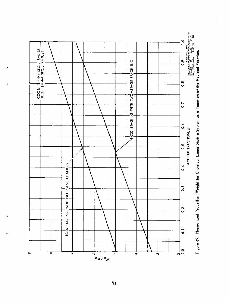
3. al = 0.111 and y = 0.01.
The performance of the two mission modes is compared in Figs. 47 to 49. These results clearly demonstrate the performance advantage of HOSS staging when a COOS is employed.
4. Final Comments
Although the performance results given above are based on idealized analyses, it can be concluded that:
1. When using HOSS staging, the lunar Space Tug should be a two-stage vehicle.
2. For a lunar shuttle system with a NOOS, the HOSS rendezvous mode seems to have a slight performance advantage over the LOSS mode.
3. Fora lunar shuttle system with a COOS, significant performance gains can be achieved by using HOSS staging.
When comparing the nuclear and chemical lunar shuttle systems, it should be noted that the performance estimates for the nuclear shuttle given in Figs. 39 to 41 may be somewhat optimistic because:
1. The effective specific impulse of the nuclear stage is reduced by in- efficient cooldown impulses (Refs. 16 to 18).
2. The mass fraction of the nuclear stage decreases substantially as its size decreases (Ref. 27).
Finally, it is recommended that more rigorous analyses of lunar shuttle modes using HOSS rendezvous should be conducted. Mission modes that utilize pro- pellants produced on the Moon's surface might also be included in these studies (see Ref. 28).
D. U s e of HOSS as a Launching Platform for Unmanned Planetary Probes
The upper stage of the HOSS-based Space Tug could also be used to boost un- manned spacecraft into transplanetary trajectories. Of course, the unmanned probe must first be transported to the HOSS with other shuttle vehicles. The transfer from Earth orbit would be accomplished with the OOS. Subsequent maneuvers are described in Fig. 50. Note the unusual use of a powered Earth swingby.
68

.
69

c
70
9 Y O
71

PROBE
TRANSP LA NE TARY
TUG 1
TRANSP LA NE TARY
1. TUG ENTER TRANS-EARTH TRAJECTORY BY APPLYING IMPULSES AT L, AND AT PERILUNE. lAVzl l00 fps (335mps)l.
INJECTION OF UNMANNED PROBE 2. NEAR PERIGEE, TUG SUPPLIES AV NEEDED FOR TRANSPLANETARY
A V = W - v p 'P
WHERE P IS THE EARTH'S GRAVITATIONAL PARAMETER rp IS THE PERIGEE RADIUS
V p IS THE ORIGINAL VELOCITY NEAR PERIGEE (almost equal to escape velocity)
V, IS THE HYPERBOLIC EXCESS VELOCITY
3. IMMEDIATELY AFTER BOOST PHASE, TUG SEPARATES FROM UNMANNED PROBE AND DEBOOSTS ITSELF INTO A TRANSLUNAR TRAJECTORY. AV COSTS ARE -ASSUMED TO BE SAME AS IN 0. (Actual AV costs would be somewhat higher due to lunar phasing requirements).
4. TUG RETURNS TO HOSS BY USING TWO-IMPULSE MANEUVER DESCRIBED IN (iJ . ~ A V = 1100 fps (335 mps) 1.
NOTE: STEPS @) AND @ ARE DELETED FOR A N EXPENDABLE TUG
Figure 50. Mission Mode for Transplanetary injection of Unmanned Probe Using Earth Swingby.
72

.
00 9
0 II x
c 8 c
/
x c c
R a Y 0
(91 OOOl) QVOlAVd
73

The performance for a typical HOSS-based Space Tug is given in Fig. 51. These results not only disclose a substantial payload dividend, but they also show that there is not a very large performance difference between the reusable and ex- pendable tug modes.
.
74

V. CONCLUSIONS AND RECOMMENDATIONS
There does not seem to be any major technical obstacle in establishing and maintaining a satellite in a halo orbit. It has been shown that the fuel expendi- ture required for stationkeeping and orbit control is quite reasonable. More- over, the simplicity of the single-axis stabilization technique presented in Section I1 should dispel any doubts about the feasibility of implementing the theoretical control laws . The importance of halo relay satellites in extending communications coverage to Earth-occulted sites on the Moon has also been demonstrated. With a halo comsat it would be possible to obtain backside tracking data from lunar orbiters. It would also be possible to operate an unmanned roving vehicle on the far side of the Moon. These tasks could not be supported very efficiently with a lunar- orbiting relay satellite system.
Because of the many apparent advantages of a HOSS over a LOSS, it is recommended that the strategy for the lunar program portion of the Manned Spaceflight Integrated Plan be reconsidered. Comprehensive studies should be initiated to determine the most efficient mission modes for a reusable Earth- Moon transportation system. Operational aspects as well as performance tradeoffs should be evaluated in these studies.
75

REFERENCES
1. Farquhar, R. W., "Station-Keeping in the Vicinity of Collinear Libration Points with an Application to a Lunar Communications Problem,1T AAS Preprint 66-132, July 1966.
2. Farquhar, R. W., "The Control and Use of Libration-Point Satellites," NASA-TR R-346, Sept. 1970. (Originally published as Stanford Univ. Report SUDAAR-350, July 1968).
3. Farquhar, R. W. and Kamel, A. A., 'Satellite Stationkeeping in the Vicinity of the Translunar Libration Point" (in preparation).
4. "Final Report for Lunar Libration Point Flight Dynamics Study," Contract NAS-5-11551, General Electric Co., April 1969.
5. Farquhar, R. W., llLimit-Cycle Analysis of a Controlled Libration-Point Satellite," Journal of the Astronautical Sciences, Vol. 17, No. 5, March- April 1970.
6. McNeely, J. T., and Ellis, W. H., "Circumlunar Communications Using Two Satellites in Lunar Polar Orbit," NASA-MSC Internal Note 68-FM-149, June 20, 1968.
7. Arndt, G. D., Batson, B. H., and Novosad, S. W., "An Analysis of the Tele- communications Performance of a Lunar Relay Satellite System," Inter- national communications Conference Proceedings, pp. 7-21 to 7-27, June 1969.
8. Breland, G. W., et. al., llLunar Far Side Communications Analysis for Satellite Relay Systems,11 Contract NAS-9-8166, TRW Systems Group, April 1970.
9. "Soviets Plan Extensive Lunar Exploration," Aviation Week and Space Tech- nology, pp. 14-16, Oct. 5, 1970.
10. Guest, J. E., and Murray, J. B., "Nature and Origin of Tsiolkovsky Crater, Lunar Farside," Planetary and Space Science, Vol. 17, No. 1, pp. 121-141, Jan. 1969.
11. "Project Linus,lf Dept. of Aerospace Engineering, Univ. of Michigan, Dec. 1969.
76

12.
13.
14.
15.
16 . 17.
18.
19.
20.
21.
22.
23.
24 . 25.
Kurland, J. R., and Goodwin, C. H., "Analysis of a Communication Satellite f o r Lunar Far-Side Exploration," Massachusetts Inst. of Tech., Center fo r Space Research Report CSR T-70-1, June 1970.
Farquhar , R. W., "Lunar Communications with Libration-Point Satellites," Journal of Spacecraft and Rockets, Vol. 4, No. 10, Oct. 1967.
Mueller, G. E., "An Integrated Space Program f o r the Next Generation," Astronautics and Aeronautics, Vol. 8, No. l., Jan. 1970.
Clarke, A. C., A Fall of Moon Dust, Harcourt, Brace and World, Inc., New York, 1961.
"Nuclear Flight System Definition Study, Phase-2 Final Report," Contract NAS-8-24714, McDonnell Douglas Astronautics Co., May 1970.
lfNuclear Flight System Definition Study, Phase-2 Final Report, I t Contract NAS-8-24715, Lockheed Missi les and Space Co., May 1970.
"Nuclear Flight System Definition Study, Phase-2 Final Report," Contract NAS-8-24975, Space Division, North American Rockwell, Aug. 1970.
Schilb, L. L., "Orbiting Propellant Depot for Chemical Orbit-to-Orbit Shuttle," Aerospace Corp., Report No. TOR-0059(6758-01)-16, Oct. 5, 1970.
!%pace Tug," Advanced Missions Program Office, NASA-MSC Project Description Document, Apr. 24, 1970.
"1967 Summer Study of Lunar Science and Exploration," NASA SP-157, 1967.
Interian, A., and Kugath, D., lfRemote Manipulators in Space," Astronautics and Aeronautics, Vol. 7, No. 5, Mav 1969.
Faust, N. L., %aunch and Polar Orbit T rans fe r Velocity Requirements for the WZ-B (Space Tug)," NASA-MSC Internal Note 70-FM-37, Mar. 9, 1970.
Hartmann, W. K., and Sullivan, R. J., ''Objectives of Permanent Lunar Bases," Report No. P-32, IIT Research Institute, Jan. 1970.
Sugar, R. D., and Winneberger, R. A., ''Mission Analysis of OOS/RNS Op- erations Between Ea r th Orbit and Lunar Orbit," Aerospace Corp., Report No. TOR-0066(5759-07)-5, June 22,1970.
77

26 . Webb, E. D., ttThree-Impulse Transfer from Lunar Orbits," Space Flight Mechanics (American Astronautical Society, New York, 196 7), Science and Technology Series, Vol. 11, pp. 541-553.
27. Osias, D. J., "Performance Comparison of Nuclear and Chemical Lunar Shuttles," Bellcomm Inc., Memorandum B70-08028, Aug. 14, 1970.
28. London, H. S., "Comparison of Several Lunar Shuttle Modes," Bellcomm. Inc., Memorandum B69-09071, Sept. 29, 1969.
78

APPENDIX A
NONLINEAR EQUATIONS OF MOTION
A complete derivation for the equations of motion of a satellite in the vicinity of the Earth-Moon L, point is given in Ref. 3. Only the final results are pre- sented here. Using the Cartesian coordinate system (x, y, z) of Fig. 2 and neglecting higher order terms, the equations of motion can be written in the expanded form
- m2 (;)3 { [' - 3 (;) '1 x - 3 (:) (:) y
. (A-la)
- ;E x + ;x z t 2 u x i + 3c, ( 1 t p)-4 xy
3 2
- -DL (1 + p)-' [4x2 - (y2 t z')] y
79

; = [vi - (1 t p ) - 3 B,] z - vx (1 t vz)x
- CX y - 2 v x 9 t. 3c, (1 t. p ) - 4 x z
t m2 (;) (. (;) (:) x t 3 (;) (;) Y
- [ L - 3 (;)2] z}
where
B, = 3.1904236569
C, = 15.845108285
D, = 91.700262028
E, = 544.05732354
( A-1 b)
1
(A-lc)
(A-2) .
The m2 terms in Eq. (A-1) are due to the direct solar perturbation. The effects of the indirect solar perturbation and the Moon's orbital eccentricity are con- tained in the quantities of p, vz , and vx which represent variations in the Earth- Moon distance and the Moon's angular rate. These quantities can be obtained from the Lunar Theory of De Pontecoulant (Refs. A-1 and A-2) and are given by
80

t - m 2 1 t m 2 c o s 2 c t - m e c o s 15 ( 2 c - 4 ) 6 8
1 9 19 - -e3 cos 4 +-e3 cos 3 4 t - m 3 cos 25 ' 8 8 6
15 5 8
- (5) cos 5 - -e y2 cos (4 - 2 7)
15 4 32
t - me2 cos 2 5 t 187 m2 e cos (2 e - 4)
me e' cos (2 5 - 4 t 4') 35 t - me e' cos (2 e - 4 - 4') - -
8 8
t + (5) e' cos (E t 4 ' ) - - 7 m2 e cos 4 12
t 33 - m2 e cos (2 6 t 4) - 105 - me2 cos (2 4 - 3 4) 16 64
- -m2 3 e' cos 4' t - 7 m2 e' cos (2 - 4 ' ) 2 2
1 2 1 2 8
- - m 2 e' cos (2 5' t 4') t - me e' cos (4 - 4')
21 8
- - me e' cos (4 t 4 ' )
uz = 2 e cos 4 t e2 cos 2 4 T
t - 11 m2 cos 2 5 t 15 - m e cos (2 - 4) 4 4
- e3 - cos 4 t 13 - e3 cos 3 4 t 85 -m3 cos 2 c 4 4 1 2

15 5 4 - 8 m (5) cos 6 - -e y2 cos (4 - 2 7 )
75 143 8 16
l5 me e' cos (2 6 - 4 + 4') 35 - 4 - 4') - - 4 4
+ - me2 cos 2 6 + - m2 e cos (2 - 4)
+ - me e' cos (2
51 105 8 32 + - m2 e cos (2 6 + 4) - - me2 cos (2 6 - 3 4)
77 8
- 3 m2 e' cos 4' t - m2 e' cos ( 2 - 4')
11 2 1 8 4
2 1 4
- - m2 e' cos (2 6 t 4') t - me e' C O S (4 - 4')
- - me e' cos (4 t 4')
vx = 3 m2 y cos sin (v' - Q)
where
(A-4)
(A-5)
(A-6)
(A-7)
(A-8)
(A-9)
.
82

(A-10) 5 4
V' = m t + E ' t 2 e ' sin+' + - e l 2 sin 2 4 '
(A-11)
. Auxilliary quantities for the direct solar perturbation can also be written in terms of theangle variables of Eqs. (A-6) to (A-11). This gives
, = c o s 6 - 2 (e s in 4 - e' sin 4 ' ) sin 6
- cos 6 {e2 t el2 t -72 - (e2 c o s 2 4 t e12 c o s 2 4 ' )
- 2 e e ' [ c o s (+-+'I - c o s (++$')I}
1 4
5 11 4 8
sin 2 4 - - e t 2 sin 24' t - m2 sin 2 6
15 4
t -m e sin ( 2 6 - 4) - 3 m e' sin +'
1 4 t - y2 cos (2 r) - 5)
i
= - sin - 2 (e sin$- e' sin+') cos 6
1 t sin e2 t e l2 t - y 2 - (e2 c o s 2 + t el2 cos 2+') { 4
- 2 e e' [ c o s (4 - 4') - c o s (4 t +')I
t - m 2 s i n 2 e 11 4 8
15 4
t - m e sin ( 2 5' - 6) - 3 m e' sin $'
(A-12)
1 4
- - y 2 sin ( 2 r ) - 6)
83
(A-13)

The astronomical constants used in the above equations are:
(A-14)
(A-15)
m : ratio of the mean motions of the Moon and the Sun (m = 0.0748013263).
e : Moon's orbital eccentricity (e = 0.054900489).
e' : Earth's orbital eccentricity (e' = 0.0167217).
(a/a') : modified ratio of the semimajor axes for the orbits of Earth and the Moon L(a/a') = 0.00250935231.
y : tangent of the mean inclination of the Moon's orbit ( y = 0.0900463066).
E , E' : mean longitudes of the epochs of the mean motions of the Moon and the
Z, 2' : mean longitudes of the lunar and solar perigees.
Sun.
R, : longitude of the mean ascending node of the Moon's orbit.
Numerical values for the last five constants can be found in Ref. A-3.
REFERENCES
A-1. De F%&mda&, G., Theorie Analytique du Systeme du Monde, Vol. 4, Bachelier, Paris, 1846.
A-2. Brown, E. W., An Introductory Treatise on the Lunar Theory, Dover Publications, New York, 1960.
A-3. The American Ephemeris and Nautical Almanac, U. S . Govt. Printing Office, Washington, D.C.
84

APPENDIX B
ANALYTICAL SOLUTION FOR LISSAJOUS NOMINAL PATH
A fourth-order analytical solution for the Lissajous nominal path is derived in Ref. 3. This solution, excluding fourth-order terms is given below (there are 278 additional terms in the fourth-order solution). For convenience, the ampli- tudes A Y and A have been renormalized by dividing these quantities by the factor y,m. in the form
With this additional normalization, the nominal path can be written
xn = m x, +m2 x2 + m 3 x3
Y, = m Y, + m2 y2 + m3 y3
zn = m zI + m2 z2 t m z3 3
where
x, = 0.341763 Ay sin T,
y, = A C O S TI Y
z1 = AZ sin T,
x2 = 0.554904 (i) sin (4 - T,>
t 0.493213 (:) Ay sin (4 t T,)
- 0.09588405 A: cos 2 T,
+ 0.128774 A: COS 2 T2
- 0.268186 A: - 0.205537 A: (B-3)
85

y2 = - 1.90554 (i) Ay c o s (4 - T,)
t 1.210699 (:) Ay c o s (4 t T,)
- 0.055296 A: s i n 2 T,
- 0.08659705 A: s i n 2 T2
z 2 = 1.052082 (c) s i n (4 t T ~ )
t 1.856918 (i) AZ s i n (4 - T2)
t 0.4241194 AY AZ cos (T2 - T,)
t 0. 1339910 Ay AZ C O S (T2 t TI) (B-5)
2 xg = (E) AY [- 0.122841 s i n (2 4 - TI)
t 0.643204 s i n (2 4 t TI)]
t (:) A: [O. 198388 cos 4 - 0.387184 cos (4 - 2T2)
t 0 .335398 c o s (4 t 2T2)l
A: [ O . 173731 cos 4 t 0.325999 cos (4 - 2T,) (:) - 0.270446 cos (4 t 2T,)l
Ay [- 1.10033 s i n (4 - T, - 2 4 ) + (:)
- 1.189247 s i n (4 t T, - 2 5 ) l

t Ay A: [- 0.430448 s i n (2T2 - T,)
- 0.031302 s i n (2T2 t T,)]
+ A i L0.027808 s i n 3T,l + C, AY s i n T,
+ Ay [- 0 .38856 s i n (T, - 2 6 )
t 0.455452 s i n (T, t 2J)I
+ 0 .741825 C O S (T1 t 25')I
87
2 y3 = (i) Ay LO. 608685 c o s ( 2 4 - T,)
t 1.407026 C O S (2q5 + Tl)]
+ (E) A: [- 0.116822 s i n q5 - 0.2147!42 s i n (4 - 2T,)
- 0.232503 s i n (4 t 2T,)]
+ (i) A; [- 0.109499 s i n q5 - 0.144553 s i n (4 - 2T1)
- 0.155751 s i n (4 t 2T,)l
+ ( E ) Ay L2.733367 cos (4 -TI - 2 6 )
- 3.848485 C O S (4 t T, - 25')I
+ Ay A: [- 1.191421 cos (2T2 - T1)
- 0.000165 cos (2T2 t T , ) ]
+ A: [- 0.027574 C O S 3T,I
+ A y [- 1.743411 C O S (Tl - 2 6 )

2 z3 = (i) AZ [- 0. 536652 s i n ( 2 4 - T,)
t 1.103381 s i n ( 2 4 t T,)]
t (i) Ay A, [- 0.353754 cos (4 - T, - Tl)
t 0 .367360 cos (4 t T, t T,)
t 0.063629 cos (4 - T, + T,)
- 0.034729 c o s (4 t T, - T1)l
AZ [- 2.353465 s i n (4 - T, - 2 c ) (:) - 3.831413 s i n (4 t T, - 2 ~ 3 1
t A: E0.017664 s i n 3T,]
t AZ A i [- 0.86684 s i n (T, - 2 T1)
- 0.044724 s i n (T, t 2 T l ) l
t AZ [- 1.487917 s i n (Tz - 2 6 )
t 0.475507 s i n (T, t 2C)l
with
t
C, = 0.09210089 (:), t 0.02905486 A:
t 0.007644849 A:
T, = W t + 8, XY
03-91
(B-10)

T, = wz t e2
1.865485
1 t m2 wx2
w = X Y
- 1.794291
1 t m2 wz2 -
2 wx 2 = 0.1387811 (k) t 0.04349909 A t
- 0.04060812 A i
(B-11)
(B-12)
(B-13)
(B-14)
2 w 22 = 0.5981779 (i) - 0.03293845 A:
t 0.03923249 A: (B-15)
7, = 0.1678331476 (B-16)
and 6, , e2 are phase angles that are usually taken to be zero. The remaining quantities are defined in Appendix A.
89

2+C A t = - E
APPENDIX C
FUEL COST FOR Z-AXIS PERIOD CONTROL
Between impulses, the satellite will follow a Lissajous nominal path. The first- order approximation to this trajectory in the yz-plane can be written as
y, = A, cos w t XY
zn = A, s i n (w t -#) X Y
where + = +,, + E t and E = w
angle, + , can be approximated by an average value through each cycle. From Fig. 11, it is easy to see that the magnitude of the control impulse is
- w = 0.0736493. Since E is small, the phase XY
where +c is the phase angle for the cycle that just misses the occulted zone. To prevent occultation, impulses must be applied at intervals of
Therefore, the average control acceleration is given by
All that remains now is to determine a value of AH that will guarrantee nonoccultation.
As shown in Fig. 10, higher-order nominal path corrections will sometimes cause the radius of the halo orbit to drop below its first-order approximation.
91
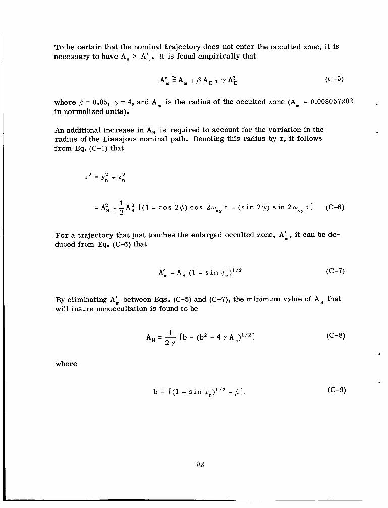
To be certain that the nominal trajectory does not enter the occulted zone, it is necessary to have A, > A:. It is found empirically that
where ,8 = 0.05, y = 4, and A, is the radius of the occulted zone (A, = 0.008057202 in normalized units).
An additional increase in A, is required to account for the variation in the radius of the Lissajous nominal path. Denoting this radius by r, it follows from Eq. (C-1) that
L
1 2
= A i t - A i [(l - c o s 2$) cos 2 w x y t - ( s i n 2$) s i n 2 w x y t ] (C-6)
For a trajectory that just touches the enlarged occulted zone, A:, it can be de- duced from Eq. (C-6) that
A: = A, (1 - s i n $ = ) ' I 2 ((3-7)
By eliminating A: between Eqs. (C-5) and (C-7), the minimum value of A, that will insure nonoccultation is found to be
(C-8) 1 A, = - [b - (b2 - 4 y 2Y .
where
b = [(I - s i n $=)112 -PI.

APPENDIX D
DERIVATION OF PERFORMANCE FUNCTION FOR A TWO-STAGE SPACE TUG
Using Eqs. (9) to (11) and Figs. 32 and 33, the basic relations for the second . stage can be written
, I with AVd = 6600 fps (2012 mps) and AVa = 8750 fps (2667 mps). Defining the
ratios
m
mc k, =- ms d
ms a k =- ms d
2
and eliminating we and wpd from Eqs. (D-1) to (D-3) gives ' .
93

where
Ka Kd - 1 Ka Kd
f =
Ka - 1 q=-
'a
For the first stage, the relations are
'G - 'p12 - wG = K 1 2 w, - wp - w,
(D-9)
(D-10)
(D-11)
with AV12 = 2550 fps (777 mps). The elimination of W, and WPl2 (D-9) to (D-11) yields
from Eqs.
(D-12)
where
M c
wG
a =-
K:2 - 1 F =
K: 2
K 1 2 - Kl 2
C =
94
(D-13)
(D-14)
(D-15)

Y
A straightforward manipulation of the foregoing equations gives the performance function
W
ms d + P = h T
95
(D-16)

APPENDIX E
DERIVATION OF PERFORMANCE FUNCTION FOR A TWO-STAGE LUNAR SHUTTLE SYSTEM
c
Using Eqs. (9) to (11) and Figs. 36 to 38, the basic relations for the tug stage can be written
*
W
(E-3) P
c ' rnsd wG =- t r n A2
I For the LOSS mission mode, A V d = 6600 fps (2012 mps) and AV, = 6200 fps (1890 mps). For the HOSS mission mode, AV, = 9150 fps (2789 mps) and AV, = 8750 fps (2667 mps). Defining the ratios
rnC k = - ms d
1
I ' ms a k =- ms d
2
and eliminating wG and wpd from Eqs. (E-1) to (E-3) yields ~'
(E-4)
(E-5)
97

where
Ka Kd - 1 Ka Kd
f =
Ka - 1 q =-
'a
For the NOOS stage, the relations are
(E-7)
(E-8)
(E-9)
(E-10)
(E-11)
When the LOSS mission mode is employed, AV,, = 13,300 fps (4054 mps). With the HOSS mission mode, AV,, = 11,400 fps (3475 mps). Using the definitions
Mc Ul = -
Ms d
(E-12)
(E-13)
msd = p M~, (0 f P 5 1) (E-14)
98

a reduction of the foregoing equations leads to the overall performance function*
where
K i 2 - 1 F =
K:2
K12 - K12
C =
(E-15)
(E-16)
(E-17)
(E-18)
"This formula can be used for a two-stage HOSS-based tug by simply replacing the function h, with Eq. (D-16). However, i t should be recalled that the same symbols have different meanings in Appendices D and E.
99

APPENDIX F
DERIVATION OF PERFORMANCE FUNCTION FOR A LUNAR SHUTTLE SYSTEM WITH A TWO-STAGE COOS
Using Eqs. (9) to (11) and Figs. 45 and 46, the basic relations for the second stage of the COOS can be written
p34 - (msd - msa) - w' WG - w wG - w - (msd - msa) - w' P P
W P w - - + msd t w; t mc - A, (F-3)
For the LOSS mission mode, AV,, = 4300 fps (1311 mps) and AV,, = 13,300 fps (4054 mps). For the HOSS mission mode, AV,, = 2400 fps (731 mps) and AV,, = 11,400 fps (3475 mps). By making use of Eqs. (F-1) to (F-3) and previous results from Appendices D and E, it can be shown that
where I *
(F-4)
mC Ul = -
msd (F-5)
1 0 1

- mSa a, - - ms d
and (msd)T is the payload delivered to the lunar surface. The function h, is obtained from Eq. (D-16) for the HOSS mission mode or from Eq. (E-6) when LOSS staging is used. (Note that the same symbols have different meanings in Appendices D, E, and F).
'For the first stage of the COOS, the relations a re
' G - 'p12 - WG WG - wp - WG = Kl*
(F-10)
(F-11)
(F-12)
with AV,, = 9000 fps (2743 mps). Finally, a little bit of algebra leads to the overall performance function
wp'= (&) [(l t y ) F - G ] (F-13) d
102

c
where
(F-14)
(F-15)
(F-16)
103
Related Documents


