THE TOWN OF MILLSBORO Request for Proposal BID Information BID Due Time 3:00 pm Bid Due Date 03/18/2022 BID Location: The Town of Millsboro 322 Wilson Highway Millsboro, DE 19966 Project Title: The Town of Millsboro 2022 Force Main Extension – Addendum No. 1 1. Delete the paragraph following Figure 1, beginning with “The Town submitted a Clean Water State Revolving Fund…” in its entirety. Replace with: “The Town has applied for funding with the United States Department of Agriculture Rural Utilities Service (USDA- RUS) for the design and construction of the project. Therefore, the consulting firm should have experience working with the USDA-RUS on construction projects similar to this project and shall provide evidence of said experience in the proposal.” 2. Project Background: Second to last sentence, remove the beginning phrase “Because the Town expects the project to be financed with DNREC CWSRF loans,” 3. Project Background, Paragraph 4: Add the following sentence before the last sentence in the paragraph: “The Town assumes for each pipe, there will be one directional drill at Ingram Pond and three road jack and bore crossings. The Town assumes that there will be up to four capped tees for future connections on the beneficial reuse main (BRM).” 4. The Town of Millsboro Standard Specifications and Details for Utilities Design and Construction are included in this Addendum. 5. Scope of Work; Design Phase: Item e. is revised as follows: Easement Exhibits: The Town anticipates that it will need to obtain easements from some property owners along the alignment. It is anticipated that about 6-10 easements will be needed. Submit a lump sum fee for the preparation of each easement agreement exhibit. Examples of previous easement agreement exhibits are available upon request. 6. Scope of Work; Design Phase: Add item f.i.: Include soil borings on both sides where the pipes cross Ingram Pond and at each road crossing. Based on the alignment, assume 3 road crossings. 7. Scope of Work; Design Phase: Item i.i: Add the following after the first sentence: “The EJCDC Construction Related Documents shall be the latest version as required by the USDA-RUS.” 8. Scope of Work; Design Phase: Item i.ii: Delete this paragraph in its entirety. 9. Scope of Work; Design Phase: Item k: Add the following sentence: “The Town will send the signed and sealed contract documents to the USDA-RUS for its review. The proposal should include responses to any comments that the USDA-RUS may have.” 10. Scope of Work; Construction Observation; Add Item 3: Backfilling of the open trench installed pipe shall conform to Town and DelDOT specifications with a compaction to 95% or more of the maximum density. This shall be proven by conducting

Welcome message from author
This document is posted to help you gain knowledge. Please leave a comment to let me know what you think about it! Share it to your friends and learn new things together.
Transcript
THE TOWN OF MILLSBORO
Request for Proposal BID Information BID Due Time 3:00 pm Bid Due Date 03/18/2022 BID Location: The Town of Millsboro 322 Wilson Highway Millsboro, DE 19966
Project Title: The Town of Millsboro 2022 Force Main Extension – Addendum No. 1
1. Delete the paragraph following Figure 1, beginning with “The Town submitted a Clean Water State Revolving Fund…” in its entirety. Replace with: “The Town has applied for funding with the United States Department of Agriculture Rural Utilities Service (USDA-RUS) for the design and construction of the project. Therefore, the consulting firm should have experience working with the USDA-RUS on construction projects similar to this project and shall provide evidence of said experience in the proposal.”
2. Project Background: Second to last sentence, remove the beginning phrase “Because the Town expects the project to be financed with DNREC CWSRF loans,”
3. Project Background, Paragraph 4: Add the following sentence before the last sentence in the paragraph: “The Town assumes for each pipe, there will be one directional drill at Ingram Pond and three road jack and bore crossings. The Town assumes that there will be up to four capped tees for future connections on the beneficial reuse main (BRM).”
4. The Town of Millsboro Standard Specifications and Details for Utilities Design and Construction are included in this Addendum.
5. Scope of Work; Design Phase: Item e. is revised as follows: Easement Exhibits: The Town anticipates that it will need to obtain easements from some property owners along the alignment. It is anticipated that about 6-10 easements will be needed. Submit a lump sum fee for the preparation of each easement agreement exhibit. Examples of previous easement agreement exhibits are available upon request.
6. Scope of Work; Design Phase: Add item f.i.: Include soil borings on both sides where the pipes cross Ingram Pond and at each road crossing. Based on the alignment, assume 3 road crossings.
7. Scope of Work; Design Phase: Item i.i: Add the following after the first sentence: “The EJCDC Construction Related Documents shall be the latest version as required by the USDA-RUS.”
8. Scope of Work; Design Phase: Item i.ii: Delete this paragraph in its entirety. 9. Scope of Work; Design Phase: Item k: Add the following sentence: “The Town will
send the signed and sealed contract documents to the USDA-RUS for its review. The proposal should include responses to any comments that the USDA-RUS may have.”
10. Scope of Work; Construction Observation; Add Item 3: Backfilling of the open trench installed pipe shall conform to Town and DelDOT specifications with a compaction to 95% or more of the maximum density. This shall be proven by conducting
THE TOWN OF MILLSBORO
a 90% modified Proctor test. The modified Proctor test shall be completed by a third party conducting the tests in a certified laboratory.
11. RFP Requirements; Part 1.a.ii: Add the following sentence: “All comments provided by the funding agency shall be addressed and contract documents revised accordingly within two weeks of receipt of funding agency comments.”
12. Other Requirements: Add Item 4.a.: Indicate experience working on design and construction projects funded with USDA-RUS funds and how the firm successfully managed the project and coordinated with USDA-RUS.
13. Consulting Firm Selection: Add the following sentences before the last sentence in the paragraph: “The Town will provide a recommendation to the funding agency following Town Council vote to award. The Town will prepare the agreement found in USDA-RUS Bulletin 1780-26 upon concurrence from the funding agency.”
14. Criteria for Awards/Evaluation: Item 1): Revise as follows: Management Plan/Evidence that design and bid schedule will be met. Weighting factor changed to 20.
15. Criteria for Awards/Evaluation: Add Item 1.a): Experience working on United States Department of Agriculture Rural Utilities Service design and construction projects. Weighting factor 15.
16. Criteria for Awards/Evaluation: Add the following sentence to Item 3: Project references shall include projects that were funded with USDA-RUS funds.
17. USDA RUS Bulletin 1780-26 is appended to this addendum. 18. Submission Deadline: Add the following sentence after the first sentence. The
submission may be submitted to the Town by electronic mail no later than 4:30 p.m. on March 18, 2022, and hardcopies of the submission shall be post marked no later than March 18, 2022.
UNITED STATES DEPARTMENT OF AGRICULTURE Rural Utilities Service
RUS BULLETIN 1780-26 Document ID: Rural Development-GD-2020-000#
SUBJECT: Guidance for the Use of Engineers Joint Contract Documents Committee (EJCDC)
Bidding and Contract Documents on Water and Waste Disposal Projects with Rural Utilities Service Financial Assistance
TO: Rural Development State Directors, Rural Utilities Service Program Directors, and State Engineers EFFECTIVE DATE: Date of approval OFFICE OF PRIMARY INTEREST: Engineering and Environmental Staff, Water and Environmental Programs (WEP), under the Rural Utilities Service (RUS), a part of Rural Development (RD), an Agency within the United States Department of Agriculture (USDA) INSTRUCTIONS: This Bulletin replaces RUS Bulletin 1780-26, dated September 7, 2017. AVAILABILITY: This Bulletin, as well as any instructions, regulations, or forms referenced in this Bulletin are available at USDA State Offices. The State Office staff is familiar with the use of the documents in their states and can answer specific questions on Agency requirements. This Bulletin is available on the website: https://www.rd.usda.gov/publications/regulations-guidelines/bulletins/water-and-environmental. PURPOSE: This Bulletin is to be used by RD staff in providing information and guidance to funding applicants/recipients (Owners) and professional consultants in the development of Bidding and Contract Documents that are legally sufficient, ensure appropriate services are provided at a reasonable fee, and expedite the achievement of the applicant’s goals. This Bulletin supports compliance with 7 CFR 1780, 2 CFR 200 and the American Iron and Steel (AIS) requirements mandated by Section 746 of Title VII of the Consolidated Appropriations Act of 2017 and subsequent statutes mandating domestic preference. The contents of this guidance document do not have the force and effect of law and are not meant to bind the public in any way. This document is intended only to provide clarity to the public regarding existing requirements under the law or agency policies. _________________________________________________ EDNA PRIMROSE Date Assistant Administrator Water and Environmental Programs
RUS Bulletin 1780-26 Page 2
TABLE OF CONTENTS 1 GENERAL 4
2 AVAILABILITY 4
3 PURPOSE 4
4 HOW TO USE THE BULLETIN 4
5 OWNER RESPONSIBILITY 5
6 DESIGN-BID-BUILD CONSTRUCTION CONTRACT DOCUMENTS (EJCDC C-SERIES) 5
7 ENGINEERING CONTRACT DOCUMENTS (EJCDC E-SERIES) 8
EXHIBITS
Exhibit A – GENERAL DOCUMENTS
Attachment 1 Certificate of Owner’s Attorney and Agency Concurrence Attachment 2 Informational Checklist for Project-Specific Waiver Requests Attachment 3 American Iron and Steel De Minimis List Format Attachment 4 General (Prime) Contractor’s Certification of Compliance Attachment 5 Manufacturer’s Certification of Compliance Attachment 6 Engineer’s Construction Certifications
Exhibit B – CONSTRUCTION CONTRACT DOCUMENTS (EJCDC C-SERIES) Attachment 1 Contract Document Checklist Attachment 2 Engineer’s Development of Advertisement for Bids Attachment 3 Engineer’s Development of Instructions to Bidders Attachment 4 Engineer’s Development of Bid Form Attachment 5 Engineer’s Development of Agreement Between Owner and Contractor Attachment 6 Engineer’s Development of Supplementary Conditions
Exhibit C – ENGINEERING CONTRACT DOCUMENTS (EJCDC E-SERIES) Attachment 1 Revisions to EJCDC E-500 Attachment 2 Engineer Agreement Certification
Exhibit D – PROCUREMENT CONTRACT DOCUMENTS (EJCDC P-SERIES) [Reserved]
Exhibit E – SHORT FORM CONTRACT DOCUMENTS [Reserved]
Exhibit F – DESIGN-BUILD CONTRACT DOCUMENTS (EJCDC D-SERIES) [Reserved]
Exhibit G – CONSTRUCTION MANAGER AT RISK CONTRACT DOCUMENTS (EJCDC CMAR-SERIES) [Reserved]
INDEX
EJCDC Contract Documents Water and Environmental Programs
RUS Bulletin 1780-26 Page 3
ABBREVIATIONS
CFR – Code of Federal Regulations EJCDC – Engineers Joint Contract Documents Committee EO – Executive Order GC – General Conditions of the Construction Contract ITB - Instructions to Bidders for Construction Contract OGC – Office of General Counsel PL – Public Law RD – Rural Development RPR – Resident Project Representative RUS – Rural Utilities Service SC – Supplementary Conditions of the Construction Contract USC – United States Code USDA – United States Department of Agriculture WEP – Water and Environmental Programs WWD – Water and Waste Disposal
DEFINITIONS Defined terms from EJCDC documents are capitalized in this Bulletin
RUS Bulletin 1780-26 Page 4
1 GENERAL
a Approved documents. The Engineers Joint Contract Documents Committee (EJCDC) developed Contract Documents, some of which are approved by Rural Utilities Service (RUS) for procurement of equipment and/or services by loan and grant recipients, subject to the modifications indicated in this Bulletin being incorporated in these documents. Approved documents are listed in the appropriate sections that follow.
b Alternative documents. Owners not wishing to use these EJCDC documents may
submit the alternative contract document(s) and a written justification of the need for its (their) use. Such documents must be modified to meet all federal and state requirements and must be approved for each project by the RD State Engineer (State Engineer) and reviewed by the United States Department of Agriculture (USDA) Office of General Counsel (OGC). When modified as described in this Bulletin, the EJCDC documents listed above have been determined to meet such requirements and do not require OGC approval.
c Phase-out of previous editions. Only current EJCDC documents should be used for
Water and Waste Disposal (WWD) projects. The most recent previous version of EJCDC documents will continue to be accepted for one year after issuance of the corresponding chapter of this Bulletin. This Bulletin does not retroactively change the status of a document already approved.
2 AVAILABILITY
The EJCDC documents are available online from any of the sponsoring organizations: the National Society of Professional Engineers (www.nspe.org); American Council of Engineering Companies (www.acec.org); and American Society of Civil Engineers (www.asce.org); or directly from EJCDC (www.ejcdc.org). EJCDC documents are proprietary and include a license agreement. State Offices will not distribute EJCDC documents for use as Contract Documents. For training purposes, or to illustrate the appropriate use of the integrated set of documents on RUS financially assisted Water and Waste Disposal (WWD) projects, the State Office may provide water-marked pdf copies of the documents.
3 PURPOSE
The EJCDC has developed Contract Documents that when assembled as described in this Bulletin are acceptable for use on WWD projects funded by RUS. This Bulletin includes a table of all the acceptable documents and instruction for modification and review of these documents. This Bulletin is not intended to make the use of EJCDC documents mandatory. Rather, this Bulletin serves to assist Owners and professional consultants who choose to use EJCDC documents in tailoring certain EJCDC bidding and contract documents for use with WWD projects financed by RUS.
4 HOW TO USE THE BULLETIN a Assembly of documents. This Bulletin explains the use of EJCDC standard contract
documents, and modifications to make them acceptable for use on WWD projects. In addition to these modifications, EJCDC guidance notes must be followed and should be deleted once the documents are completed.
RUS Bulletin 1780-26 Page 5
b Revising text. This Bulletin may be used in one of three ways:
(1) The Engineer makes all the edits to the purchased EJCDC documents when these documents will be used for RUS funded WWD projects. Changes to EJCDC standard language, whether the changes are as per this Bulletin or by the Owner and its Engineer, are made using bold type additions and single-line strike-out deletions, showing all revisions.
(2) Exhibits are inserted in the Bidding and Contract Documents at the appropriate
location. (3) The Engineer requests from EJCDC free, editable copies of the certain
documents with WEP-required edits already included, upon proof of purchase of EJCDC documents.
c Guidance notes. Guidance notes in blue boxes in the EJCDC documents shall be
implemented as deemed appropriate by Owner and Engineer and deleted prior to finalization of the documents.
5 OWNER RESPONSIBILITY
a Verify bulletin is current. Before an Owner or their Engineer proceeds with the
development of a set of Bidding Documents, they should contact the State Engineer to verify they have the most current information specific to the type of project and state or other jurisdiction where the project is located.
b Contractual and administrative issues. The Owner is responsible for settling all contractual and administrative issues arising out of procurement as a condition of receiving funding assistance from RUS. These include but are not limited to: source evaluation; protests; disputes; and claims. Matters concerning violations of laws are to be referred to the applicable local, state, or federal authority.
c Modifications. It is WEP policy that when Owners choose to use the EJCDC documents they do so with minimal modification. However, WEP recognizes each project is unique and that modifications may be necessary to satisfy project requirements or state statutes. If changes must be made to the standard documents and/or the modifications in the attached exhibits to address project-specific issues, they must be made via bold type additions and single-line strike-out deletions showing all revisions. Because the EJCDC documents are fully integrated, when making a modification in one document Owners must ensure that appropriate modifications are made in all affected documents.
6 DESIGN-BID-BUILD CONSTRUCTION CONTRACT DOCUMENTS (EJCDC C-
SERIES)
a Use of EJCDC C-series for WWD projects. The Engineers Joint Contract Documents Committee (EJCDC) developed its Construction Contract Documents (C-series), 2018 edition, for use in traditional design-bid-build projects. This Bulletin consists of exhibits and attachments with modifications that, when combined with the standard EJCDC documents and appropriate Drawings, Specifications and other documents,
RUS Bulletin 1780-26 Page 6
create a complete set of acceptable Construction Contract Documents for use on WWD projects. Contract packages must be assembled in accordance with the following notes, requirements of Exhibit A, Attachments 2-6, and Exhibit B, Attachments 2-6, and the table later in this Bulletin. EJCDC provides guidance for use of various clauses throughout the documents; those guidance notes must be followed and should be deleted once the documents are completed.
b Approved documents. The following EJCDC 2018 edition C-series documents are
approved by WEP for procurement of construction services by loan and grant recipients, subject to the modifications indicated in this Bulletin being incorporated in these documents. The documents are listed in the order of their use:
(1) ADVERTISEMENT FOR BIDS FOR CONSTRUCTION CONTRACT,
EJCDC C-111
(2) INSTRUCTIONS TO BIDDERS FOR CONSTRUCTION CONTRACT, EJCDC C-200
(3) BID FORM FOR CONSTRUCTION CONTRACT, EJCDC C-410
(4) BID BOND (PENAL SUM FORM), EJCDC C-430
(5) QUALIFICATIONS STATEMENT, EJCDC C-451
(6) NOTICE OF AWARD, EJCDC C-510
(7) AGREEMENT BETWEEN OWNER AND CONTRACTOR FOR CONSTRUCTION CONTRACT (STIPULATED PRICE), EJCDC C-520
(8) PERFORMANCE BOND, EJCDC C-610
(9) PAYMENT BOND, EJCDC C-615
(10) STANDARD GENERAL CONDITIONS OF THE CONSTRUCTION CONTRACT, EJCDC NO. C-700
(11) SUPPLEMENTARY CONDITIONS OF THE CONSTRUCTION CONTRACT, EJCDC C-800
(12) NOTICE TO PROCEED, EJCDC C-550
(13) APPLICATION FOR PAYMENT, EJCDC C-620 (14) WORK CHANGE DIRECTIVE, EJCDC C-940 (15) CHANGE ORDER, EJCDC C-941 (16) FIELD ORDER, EJCDC C-942 (17) CERTIFICATE OF SUBSTANTIAL COMPLETION, EJCDC C-625
RUS Bulletin 1780-26 Page 7
(18) NOTICE OF ACCEPTABILITY OF WORK, EJCDC C-626
c Previous editions. The current (2018) EJCDC C-series documents should be used for
WWD projects. The 2013 C-series will continue to be accepted until December 31, 2020. This Bulletin does not retroactively change the status of a document already approved.
d General Conditions. The EJCDC General Conditions (C-700) should not be modified.
Changes to C-700 should only be made via the Supplementary Conditions.
e EJCDC suggested language. The Instructions to Bidders and Supplementary Conditions must be developed by the Engineer based on EJCDC guidance documents and the instructions and exhibits below. The State Engineer must verify that the instructions and exhibits below were followed prior to any advertisement for bids.
f EJCDC standard language. The Bid Form and the Agreement Between Owner and Contractor are standard documents from EJCDC but must be modified before use on a RUS funded project. The State Engineer must verify that the instructions and exhibits below were followed prior to advertisement for bidding.
g Project signs. It is customary that project signs identifying the Owner, Contractor, Engineer, and funding agencies be displayed during project construction. The Engineer should contact the State Engineer for specific requirements and include the sign standard in the contract package.
h Number of copies of Bidding Documents. One copy of the draft Bidding Documents (defined in EJCDC C-700 Article 1.01), which include but are not limited to those listed in the checklist in Exhibit B, Attachment 1 of this Bulletin, must be submitted to the State Engineer for review and acceptance prior to advertisement for bid. One copy of the as-bid Bidding Documents is to be provided to the State Engineer within five days of the advertisement to bid, and one copy must be provided to the RD Area Specialist prior to issuance of the Notice to Proceed. Addenda shall be submitted to the State Engineer for review and acceptance prior to issuance, with a copy provided to the State Engineer and Area Specialist after issuance. Consult with the State Engineer and Area Specialist for the preferred method of submission (electronic vs. paper).
i State Engineer Acceptance/Approval/Concurrence Prior to Bid, Award and Construction. All Contract Documents must be accepted by the State Engineer prior to advertisement for bids. The State Engineer must concur with the recommendation to award, and the executed Contract Documents must be concurred with by the State Engineer prior to construction. The Certificate of Owner’s Attorney and Agency Concurrence document (Exhibit A, Attachment 1) must be used for this purpose.
j Assembly of Bidding and Contract Documents. Refer to the checklist in Exhibit B, Attachment 1. Acceptable edits to the EJCDC documents C-111, C-200, C-410, C-520, and C-800, are found in Exhibit B, Attachments 2-5.
RUS Bulletin 1780-26 Page 8
7 ENGINEERING CONTRACT DOCUMENTS (EJCDC E-SERIES)
a Use of EJCDC E-series for WWD projects. The Engineers Joint Contract Documents Committee (EJCDC) developed its Engineering Family Documents (E-series), 2014 edition, for use in traditional design-bid-build projects. This Bulletin consists of an exhibit and attachments with acceptable modifications that, when combined with the standard EJCDC document, create a complete and acceptable Agreement Between Owner & Engineer for Professional Services (Engineer Agreement) for use on WWD projects. The Engineer Agreement must be assembled in accordance with the following notes and requirements of Exhibit C, Attachments 1 and 2. EJCDC provides guidance for use of various clauses throughout the documents; those guidance notes must be followed and should be deleted once the documents are completed.
b Approved documents. The following EJCDC 2014 edition E-series document is
approved by WEP for procurement of engineering services by loan and grant recipients, subject to the modifications indicated in this Bulletin being incorporated in these documents:
(1) AGREEMENT BETWEEN OWNER & ENGINEER FOR
PROFESSIONAL SERVICES, EJCDC E-500
c Previous editions. The current (2014) EJCDC E-series documents should be used for WWD projects.
d EJCDC standard language. The Engineer Agreement is a standard document from
EJCDC but must be modified before use on each WEP funded project. The State Engineer must verify that the instructions and exhibits below were followed prior to acceptance by the Owner and Engineer.
e Process. Instructions to modify EJCDC E-500 (2014) prior to use on RUS funded
WWD projects are as follows:
(1) Engineer must attach the list of “Revisions to the EJCDC E-500 (2014)” (Exhibit C Attachment 1 of this Bulletin) to the Agreement as an addendum or make the specific changes listed using bold-type additions and single-line strike-out deletions.
(2) Project-specific requirements may be added to Exhibit J of E-500 (2014). (3) Owner and Engineer must select a payment method from Exhibit C of E-500
(2014) (see below). (4) Owner and Engineer must sign the Agreement on page 19 of EJCDC E-500
and include, complete and sign the RUS Certification Page (Exhibit C Attachment 2 of this Bulletin).
(5) Agency must review to ensure changes were made as necessary or revisions were attached and that the certification is attached, completed, and acceptable.
(6) Agency completes and signs the RUS Certification page.
f Seismic acknowledgments. For each applicable structure, borrowers and grant recipients must provide RUS a written acknowledgment from a registered architect or engineer responsible for the design stating that seismic provisions pursuant to 7 CFR 1792 will be used in the design of the structure.
RUS Bulletin 1780-26 Page 9
(1) If Drawings and Specifications are required to be submitted to RUS, this
acknowledgement shall be on the title page of the Drawings included with the final Drawings and Specifications. This acknowledgement will include the identification and date of the model code or standard that is used in the seismic design of the structure. The Drawings and Specifications must be dated, signed, and sealed by a registered architect or engineer.
(2) For projects in which Drawings and Specifications are not submitted, this acknowledgement shall be in the form of a statement from the architect or engineer responsible for the building design. The statement shall identify the model code or standard identified that is used in the seismic design of the building or buildings and, shall be dated and signed.
g Payment for Services. The standard Exhibit C of E-500 (2014), “Payments to Engineer
for Services and Reimbursable Expenses”, should be used along with the E-500 (2014) Engineer Agreement, but only the following Compensation Packets are allowed for use with RUS funded projects (other Compensation Packets should not be used):
(1) Allowed for Basic Services:
Lump Sum (Compensation Packet C-1) Standard Hourly Rates (Compensation Packet BC-2)
(2) Allowed for RPR Services:
Lump Sum (Compensation Packet RPR-1) Standard Hourly Rates (Compensation Packet RPR-2)
(3) Allowed for Additional Services: Standard Hourly Rates (Compensation Packet AS-1)
h Insurance. E-500 (2014) Exhibit G “Insurance” amounts should be established by the
Owner based on advice from the Owner’s attorney or a risk manager hired by the Owner.
i Limits of Liability. E-500 (2014) Exhibit I, “Limitations of Liability”, is permissible to be used on RUS funded projects.
j Number of copies of Engineer Agreement. One copy of the draft Engineer Agreement will be submitted to the State Engineer for review and preliminary concurrence prior to signing by the Owner and Engineer. Four copies of the signed Engineer Agreement are to be provided to the State Engineer for formal concurrence; one copy each will be sent to the Owner, Engineer, and RD Area Specialist. Amendments shall be submitted to the State Engineer for review and preliminary concurrence prior to signing, with four executed copies provided to the State Engineer for formal concurrence; one copy will be sent to the Owner, Engineer, and RD Area Specialist after the State Engineer concurs. Consult with the State Engineer and Area Specialist for the preferred method of submission (electronic vs. paper).
k State Engineer Concurrence. The executed Engineer Agreement will be concurred with
by the State Engineer prior to Agency concurrence in any payment of RUS funding for engineering services.

RUS Bulletin 1780-26 Page 10
l Assembly of Engineer Agreement. Refer to RUS’ acceptable edits to EJCDC E-500 (2014), which are found in Exhibit C, Attachments 1 and 2.
RUS Bulletin 1780-26 Exhibit A
Exhibit A – GENERAL DOCUMENTS
Notes to User: This Attachment contains exhibits applicable to most WWD projects.

RUS Bulletin 1780-26 Exhibit A, Attachment 1
Page 1
CERTIFICATE OF OWNER’S ATTORNEY AND AGENCY CONCURRENCE
Notes to User: This exhibit consists of two certificates, on a single page, to be attached to the Contract and signed upon execution. The first is a certificate to be signed by the Owner’s attorney and the second is the concurrence to be signed by the State Engineer. This page is to be inserted after the Agreement between Owner and Contractor for Construction Contract (Stipulated Price) (EJCDC C-520, 2018) in the Construction Contract Documents. CERTFICATE OF OWNER’S ATTORNEY PROJECT NAME: CONTRACTOR NAME AND CONTRACT NUMBER: I, the undersigned, ___________________________________, the duly authorized and acting legal representative of __________________________________________________, do hereby certify as follows: I have examined the attached Contract(s) and performance and payment bond(s) and the manner of execution thereof, and I am of the opinion that each of the aforesaid agreements is adequate and has been duly executed by the proper parties thereto acting through their duly authorized representatives; that said representatives have full power and authority to execute said agreements on behalf of the respective parties named thereon; and that the foregoing agreements constitute valid and legally binding obligations upon the parties executing the same in accordance with the terms, conditions, and provisions thereof. Name Date AGENCY CONCURRENCE As lender or insurer of funds to defray the costs of this Contract, and without liability for any payments thereunder, the Agency hereby concurs in the form, content, and execution of this Agreement. Agency Representative Date Name
RUS Bulletin 1780-26 Exhibit A, Attachment 2
Page 1
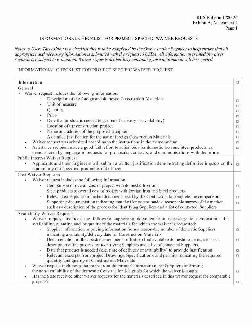
INFORMATIONAL CHECKLIST FOR PROJECT-SPECIFIC WAIVER REQUESTS
Notes to User: This exhibit is a checklist that is to be completed by the Owner and/or Engineer to help ensure that all appropriate and necessary information is submitted with the request to USDA. All information presented in waiver requests are subject to evaluation. Waiver requests deliberately containing false information will be rejected.
INFORMATIONAL CHECKLIST FOR PROJECT SPECIFIC WAIVER REQUEST
Information □ General • Waiver request includes the following information:
- Description of the foreign and domestic Construction M aterials - Unit of measure - Quantity - Price - Date that product is needed (e.g. time of delivery or availability) - Location of the construction project - Name and address of the proposed Supplier - A detailed justification for the use of foreign Construction Materials
• Waiver request was submitted according to the instructions in the memorandum • Assistance recipient made a good faith effort to solicit bids for domestic Iron and Steel products, as
demonstrated by language in requests for proposals, contracts, and communications with the prime
□ □ □ □ □ □ □ □ □ □ Public Interest Waiver Request
• Applicants and their Engineers will submit a written justification demonstrating definitive impacts on the community if a specified product is not utilized.
□
Cost Waiver Requests • Waiver request includes the following information:
- Comparison of overall cost of project with domestic Iron and Steel products to overall cost of project with foreign Iron and Steel products
- Relevant excerpts from the bid documents used by the Contractors to complete the comparison - Supporting documentation indicating that the Contractor made a reasonable survey of the market,
such as a description of the process for identifying Suppliers and a list of contacted Suppliers
□ □ □
Availability Waiver Requests • Waiver request includes the following supporting documentation necessary to demonstrate the
availability, quantity, and /or quality of the materials for which the waiver is requested: - Supplier information or pricing information from a reasonable number of domestic Suppliers
indicating availability/delivery date for Construction Materials - Documentation of the assistance recipient's efforts to find available domestic sources, such as a
description of the process for identifying Suppliers and a list of contacted Suppliers. - Date that product is needed (e.g. time of delivery or availability) to provide justification - Relevant excerpts from project Drawings, Specifications, and permits indicating the required
quantity and quality of Construction Materials • Waiver request includes a statement from the prime Contractor and/or Supplier confirming
the non-availability of the domestic Construction Materials for which the waiver is sought • Has the State received other waiver requests for the materials described in this waiver request for comparable
projects?
□ □ □ □
□
□
RUS Bulletin 1780-26 Exhibit A, Attachment 3
Page 1
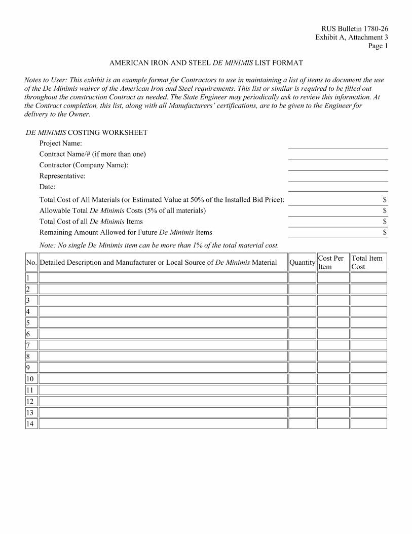
AMERICAN IRON AND STEEL DE MINIMIS LIST FORMAT
Notes to User: This exhibit is an example format for Contractors to use in maintaining a list of items to document the use of the De Minimis waiver of the American Iron and Steel requirements. This list or similar is required to be filled out throughout the construction Contract as needed. The State Engineer may periodically ask to review this information. At the Contract completion, this list, along with all Manufacturers’ certifications, are to be given to the Engineer for delivery to the Owner.
DE MINIMIS COSTING WORKSHEET Project Name: Contract Name/# (if more than one) Contractor (Company Name): Representative: Date: Total Cost of All Materials (or Estimated Value at 50% of the Installed Bid Price): $ Allowable Total De Minimis Costs (5% of all materials) $ Total Cost of all De Minimis Items $ Remaining Amount Allowed for Future De Minimis Items $ Note: No single De Minimis item can be more than 1% of the total material cost.
No. Detailed Description and Manufacturer or Local Source of De Minimis Material Quantity Cost Per Item
Total Item Cost
1
2
3
4
5
6
7
8
9
10
11
12
13
14
RUS Bulletin 1780-26 Exhibit A, Attachment 4
Page 1
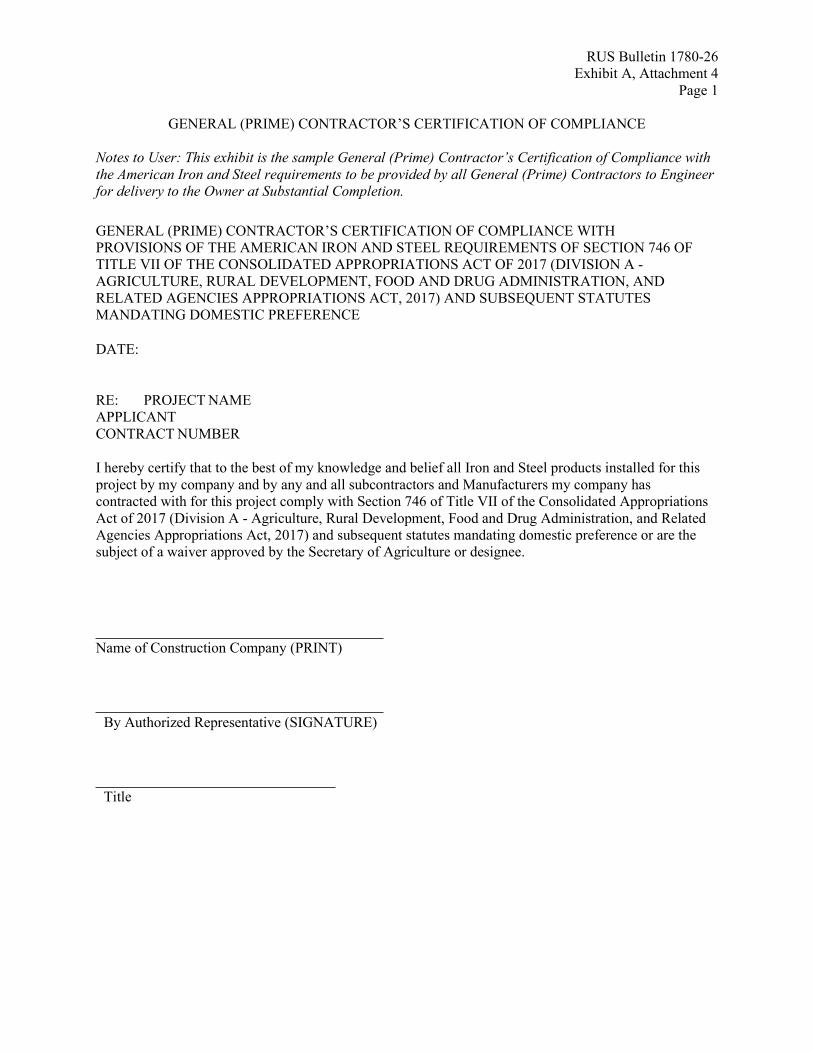
GENERAL (PRIME) CONTRACTOR’S CERTIFICATION OF COMPLIANCE Notes to User: This exhibit is the sample General (Prime) Contractor’s Certification of Compliance with the American Iron and Steel requirements to be provided by all General (Prime) Contractors to Engineer for delivery to the Owner at Substantial Completion. GENERAL (PRIME) CONTRACTOR’S CERTIFICATION OF COMPLIANCE WITH PROVISIONS OF THE AMERICAN IRON AND STEEL REQUIREMENTS OF SECTION 746 OF TITLE VII OF THE CONSOLIDATED APPROPRIATIONS ACT OF 2017 (DIVISION A - AGRICULTURE, RURAL DEVELOPMENT, FOOD AND DRUG ADMINISTRATION, AND RELATED AGENCIES APPROPRIATIONS ACT, 2017) AND SUBSEQUENT STATUTES MANDATING DOMESTIC PREFERENCE DATE: RE: PROJECT NAME
APPLICANT CONTRACT NUMBER
I hereby certify that to the best of my knowledge and belief all Iron and Steel products installed for this project by my company and by any and all subcontractors and Manufacturers my company has contracted with for this project comply with Section 746 of Title VII of the Consolidated Appropriations Act of 2017 (Division A - Agriculture, Rural Development, Food and Drug Administration, and Related Agencies Appropriations Act, 2017) and subsequent statutes mandating domestic preference or are the subject of a waiver approved by the Secretary of Agriculture or designee.
Name of Construction Company (PRINT)
By Authorized Representative (SIGNATURE)
Title

RUS Bulletin 1780-26 Exhibit A, Attachment 5
Page 1
MANUFACTURER’S CERTIFICATION OF COMPLIANCE
Notes to User: This exhibit is the sample Manufacturer’s Certification of Compliance with the American Iron and Steel requirements to be provided by all Manufacturers of American Iron and Steel covered items, to be submitted by Contractor to the Engineer with the corresponding Shop Drawing submittal for delivery to the Owner at Substantial Completion.
EXAMPLE OF A MANUFACTURER’S CERTIFICATION OF COMPLIANCE WITH PROVISIONS OF THE AMERICAN IRON AND STEEL (AIS) REQUIREMENTS OF SECTION 746 OF TITLE VII OF THE CONSOLIDATED APPROPRIATIONS ACT OF 2017 (DIVISION A - AGRICULTURE, RURAL DEVELOPMENT, FOOD AND DRUG ADMINISTRATION, AND RELATED AGENCIES APPROPRIATIONS ACT, 2017) AND SUBSEQUENT STATUTES MANDATING DOMESTIC PREFERENCE
Date:
Company Name:
Company Address:
Subject: American Iron and Steel (AIS) Certification for Project (X), Owner’s Name, and Contract Number
I, (company representative), certify that the (melting, bending, galvanizing, cutting, etc.) processes for (manufacturing or fabricating) the following products and/or material shipped or provided for the subject project is in full compliance with the AIS requirement as mandated by Section 746 of Title VII of the Consolidated Appropriations Act of 2017 (Division A - Agriculture, Rural Development, Food and Drug Administration, and Related Agencies Appropriations Act, 2017) and subsequent statutes mandating domestic preference. Item, Products and/or Materials, and location of delivery (City, State):
1.
2. Such processes for AIS took place at the following location:
(City, State)
Authorized Company Representative Signature Notes: Authorized signature will be Manufacturer’s representative, not the material distributor or Supplier. If any of the above compliance statements change while providing materials to this project, please immediately notify the person(s) who is requesting to use your product(s).
RUS Bulletin 1780-26 Exhibit A, Attachment 6
Page 1
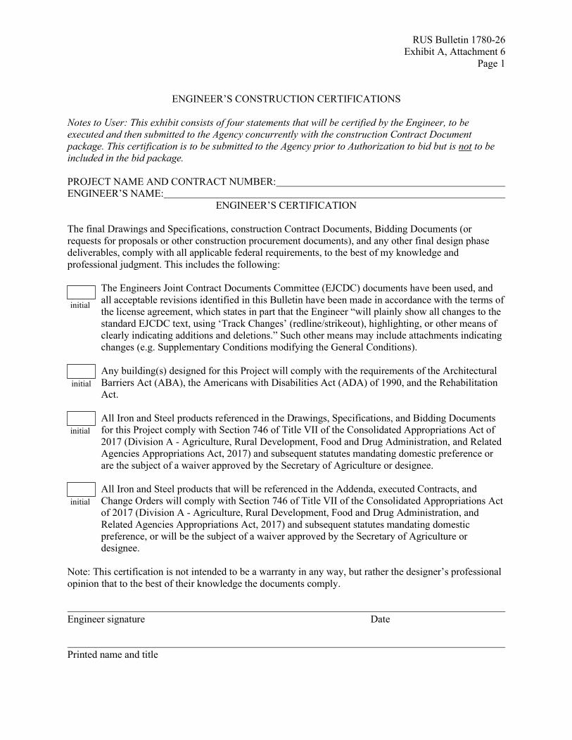
ENGINEER’S CONSTRUCTION CERTIFICATIONS
Notes to User: This exhibit consists of four statements that will be certified by the Engineer, to be executed and then submitted to the Agency concurrently with the construction Contract Document package. This certification is to be submitted to the Agency prior to Authorization to bid but is not to be included in the bid package.
PROJECT NAME AND CONTRACT NUMBER: ENGINEER’S NAME:
ENGINEER’S CERTIFICATION The final Drawings and Specifications, construction Contract Documents, Bidding Documents (or requests for proposals or other construction procurement documents), and any other final design phase deliverables, comply with all applicable federal requirements, to the best of my knowledge and professional judgment. This includes the following:
The Engineers Joint Contract Documents Committee (EJCDC) documents have been used, and all acceptable revisions identified in this Bulletin have been made in accordance with the terms of the license agreement, which states in part that the Engineer “will plainly show all changes to the standard EJCDC text, using ‘Track Changes’ (redline/strikeout), highlighting, or other means of clearly indicating additions and deletions.” Such other means may include attachments indicating changes (e.g. Supplementary Conditions modifying the General Conditions). Any building(s) designed for this Project will comply with the requirements of the Architectural Barriers Act (ABA), the Americans with Disabilities Act (ADA) of 1990, and the Rehabilitation Act.
All Iron and Steel products referenced in the Drawings, Specifications, and Bidding Documents for this Project comply with Section 746 of Title VII of the Consolidated Appropriations Act of 2017 (Division A - Agriculture, Rural Development, Food and Drug Administration, and Related Agencies Appropriations Act, 2017) and subsequent statutes mandating domestic preference or are the subject of a waiver approved by the Secretary of Agriculture or designee. All Iron and Steel products that will be referenced in the Addenda, executed Contracts, and Change Orders will comply with Section 746 of Title VII of the Consolidated Appropriations Act of 2017 (Division A - Agriculture, Rural Development, Food and Drug Administration, and Related Agencies Appropriations Act, 2017) and subsequent statutes mandating domestic preference, or will be the subject of a waiver approved by the Secretary of Agriculture or designee.
Note: This certification is not intended to be a warranty in any way, but rather the designer’s professional opinion that to the best of their knowledge the documents comply. Engineer signature Date Printed name and title
initial
initial
initial
initial
Exhibit B - CONSTRUCTION CONTRACT DOCUMENTS (EJCDC C-SERIES)
Notes to User: This Attachment contains exhibits applicable to WWD projects when using EJCDC Construction Contract Documents (C-series).
RUS Bulletin 1780-26 Exhibit B, Attachment 1
Page 1
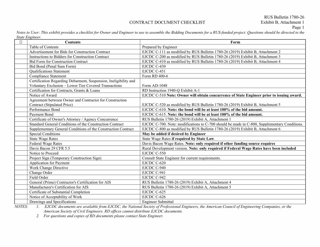
CONTRACT DOCUMENT CHECKLIST
Notes to User: This exhibit provides a checklist for Owner and Engineer to use to assemble the Bidding Documents for a RUS-funded project. Questions should be directed to the State Engineer. Contents Form Table of Contents Prepared by Engineer Advertisement for Bids for Construction Contract EJCDC C-111 as modified by RUS Bulletin 1780-26 (2019) Exhibit B, Attachment 2 Instructions to Bidders for Construction Contract EJCDC C-200 as modified by RUS Bulletin 1780-26 (2019) Exhibit B, Attachment 3 Bid Form for Construction Contract EJCDC C-410 as modified by RUS Bulletin 1780-26 (2019) Exhibit B, Attachment 4 Bid Bond (Penal Sum Form) EJCDC C-430 Qualifications Statement EJCDC C-451 Compliance Statement Form RD 400-6
Certification Regarding Debarment, Suspension, Ineligibility and Voluntary Exclusion – Lower Tier Covered Transactions Form AD-1048
Certification for Contracts, Grants & Loans RD Instruction 1940-Q Exhibit A-1 Notice of Award EJCDC C-510 Note: Owner will obtain concurrence of State Engineer prior to issuing award.
Agreement between Owner and Contractor for Construction Contract (Stipulated Price) EJCDC C-520 as modified by RUS Bulletin 1780-26 (2019) Exhibit B, Attachment 5
Performance Bond EJCDC C-610. Note: the bond will be at least 100% of the bid amount. Payment Bond EJCDC C-615. Note: the bond will be at least 100% of the bid amount. Certificate of Owner's Attorney / Agency Concurrence RUS Bulletin 1780-26 (2019) Exhibit A, Attachment 1 Standard General Conditions of the Construction Contract EJCDC C-700. Note: modifications to C-700 should be made in C-800, Supplementary Conditions. Supplementary General Conditions of the Construction Contract EJCDC C-800 as modified by RUS Bulletin 1780-26 (2019) Exhibit B, Attachment 6 Special Conditions May be added if desired by Engineer State Wage Rates State Wage Rates if required by State Law. Federal Wage Rates Davis Bacon Wage Rates. Note: only required if other funding source requires Davis Bacon 29 CFR 5.5 Rural Development version. Note: only required if Federal Wage Rates have been included Notice to Proceed EJCDC C-550 Project Sign (Temporary Construction Sign) Consult State Engineer for current requirements. Application for Payment EJCDC C-620 Work Change Directive EJCDC C-940 Change Order EJCDC C-941 Field Order EJCDC C-942 General (Prime) Contractor's Certification for AIS RUS Bulletin 1780-26 (2019) Exhibit A, Attachment 4 Manufacturer's Certification for AIS RUS Bulletin 1780-26 (2019) Exhibit A, Attachment 5 Certificate of Substantial Completion EJCDC C-625 Notice of Acceptability of Work EJCDC C-626 Drawings and Specifications Engineer Submittal
NOTES: 1. EJCDC documents are available from EJCDC, the National Society of Professional Engineers, the American Council of Engineering Companies, or the American Society of Civil Engineers. RD offices cannot distribute EJCDC documents.
2. For questions and copies of RD documents please contact State Engineer.
RUS Bulletin 1780-26 Exhibit B, Attachment 2
Page 1
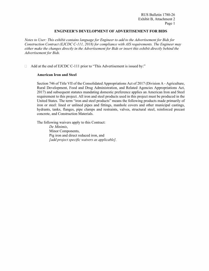
ENGINEER’S DEVELOPMENT OF ADVERTISEMENT FOR BIDS
Notes to User: This exhibit contains language for Engineer to add to the Advertisement for Bids for Construction Contract (EJCDC C-111, 2018) for compliance with AIS requirements. The Engineer may either make the changes directly in the Advertisement for Bids or insert this exhibit directly behind the Advertisement for Bids.
� Add at the end of EJCDC C-111 prior to “This Advertisement is issued by:”
American Iron and Steel Section 746 of Title VII of the Consolidated Appropriations Act of 2017 (Division A - Agriculture, Rural Development, Food and Drug Administration, and Related Agencies Appropriations Act, 2017) and subsequent statutes mandating domestic preference applies an American Iron and Steel requirement to this project. All iron and steel products used in this project must be produced in the United States. The term “iron and steel products” means the following products made primarily of iron or steel: lined or unlined pipes and fittings, manhole covers and other municipal castings, hydrants, tanks, flanges, pipe clamps and restraints, valves, structural steel, reinforced precast concrete, and Construction Materials.
The following waivers apply to this Contract:
De Minimis, Minor Components, Pig iron and direct reduced iron, and [add project specific waivers as applicable].
RUS Bulletin 1780-26 Exhibit B, Attachment 3
Page 1
ENGINEER’S DEVELOPMENT OF INSTRUCTIONS TO BIDDERS Notes to User: This exhibit contains a list of changes to be made by Engineer to the Instructions to Bidders for Construction Contract (EJCDC C-200, 2018). The Engineer will develop the Instructions to Bidders using EJCDC C-200 (2018) and the instructions provided below. In addition, Engineer will ensure that any applicable state or federal wage rate requirements are added at Article 24. RD does not require the use of Davis Bacon Wage rates in most cases, but other sources of federal funds may. If other funding sources involved in the project require the use of Davis Bacon Wage rates, RD’s version of Davis Bacon 29 CFR 5.5 will be added to these construction Contract Documents, as listed in the checklist in Exhibit A. The Engineer may either make the changes below directly to the Instructions to Bidders or insert this exhibit directly behind the Instructions to Bidders. � Article 3.02 – Delete in its entirety and insert “Deleted”. � Article 8.01 – Add to the end of the paragraph “Bid security must be at least 5% of the Bidder’s
maximum Bid price.” � Article 9.02 – Delete in its entirety and insert “Deleted”. � Article 10.01 – Delete in its entirety and insert “Deleted”. � Article 10.02 – Insert after the sentence that starts “Each such request…: “Each such request shall
include the Manufacturer’s Certification for Compliance with AIS. Refer to the Manufacturer’s Certification form provided in these construction Contract Documents."
� Article 10.02 – Add to the end of this paragraph: “Substitutes and “or-equal” materials and equipment
may be proposed by Contractor in accordance with Paragraphs 7.05 and 7.06 of the General Conditions after the Effective Date of the Contract. Each such request shall include Manufacturer’s Certification letter to document compliance with AIS requirements of Section 746 of Title VII of the Consolidated Appropriations Act of 2017 (Division A - Agriculture, Rural Development, Food and Drug Administration, and Related Agencies Appropriations Act, 2017) and subsequent statutes mandating domestic preference, if applicable. Refer to Manufacturer’s Certification Letter provided in these Contract Documents.”
� Article 11.01 – Delete in its entirety and insert “Deleted”.
� Article 11.05 – Add the following:
11.05 – The Contractor shall not award work to Subcontractor(s) in excess of the limits stated in SC 7.07A.
� Article 13.04 – Delete in its entirety and insert “Deleted”. � Article 13.07 – Delete in its entirety and insert “Deleted”. � Article 18.05.E – Delete in its entirety and insert “Deleted”. � Article 18.05.F – Delete in its entirety and insert “Deleted”.

RUS Bulletin 1780-26 Exhibit B, Attachment 3
Page 2
� Add the following, renumbering if Articles 21 and/or 22 are not used:
ARTICLE 23 – FEDERAL REQUIREMENTS 23.01 If the contract price is in excess of $100,000, provisions of the Contract Work Hours and
Safety Standards Act at 29 CFR 5.5(b) apply. 23.02 Federal requirements at Article 19 of the Supplementary Conditions apply to this
Contract. 23.03 American Iron and Steel requirements apply to this project.
RUS Bulletin 1780-26 Exhibit B, Attachment 4
Page 1
ENGINEER’S DEVELOPMENT OF BID FORM
Notes to User: This exhibit contains a list of changes to be made by Engineer to the Bid Form for Construction Contract (EJCDC C-410, 2018). The Engineer may either make the changes directly to the Bid Form or insert this exhibit directly behind the Bid Form. � Article 2.01 Delete the “ and” at the end of 2.01.F
Delete the existing text for 2.01.G and add the following text and the referenced attachments to the Bidding Documents:
G. If Bid amount exceeds $10,000, signed Compliance Statement (RD 400-6). Refer to specific equal
opportunity requirements set forth in the Supplementary Conditions of the Construction Contract (EJCDC C-800);
H. If Bid amount exceeds $25,000, signed Certification Regarding Debarment, Suspension,
Ineligibility and Voluntary Exclusion - Lower Tier Covered Transactions (AD-1048); I. If Bid amount exceeds $100,000, signed RD Instruction 1940-Q Exhibit A-1, Certification for
Contracts, Grants, and Loans.” J. [List other documents and edit above as pertinent].
� Article 4 – Delete in its entirety and insert “Deleted”. � Article 5 – Delete in its entirety and insert “Deleted”. � Article 6.02 – Delete in its entirety and insert “Deleted”.
� Article 6.03 – Delete in its entirety and insert “Deleted”. � Article 8.01.A.3 – Delete the period at the end of Article 8.018.A.3 and insert the following language:
“, including all American Iron and Steel requirements.”
RUS Bulletin 1780-26 Exhibit B, Attachment 5
Page 1
ENGINEER’S DEVELOPMENT OF AGREEMENT BETWEEN OWNER AND CONTRACTOR Notes to User: This exhibit contains a list of changes to be made by the Engineer to the Agreement between Owner and Contractor for Construction Contract (Stipulated Price) (EJCDC C-520, 2018). The Engineer may either make the changes directly to the Agreement or insert this exhibit directly behind the Agreement. � Article 4.05.C – Delete in its entirety and insert “Deleted”.
� Article 6.02.A.1.a – Replace “[number]” with “95”. � Article 6.02.A.1.a(1) – Delete in its entirety and insert “Deleted”.
� Article 6.02.A.1.b – Replace “[number]” with “95”.
� Article 6.02.B – After “Substantial Completion” insert “of the entire construction to be provided
under the construction Contract Documents”.
RUS Bulletin 1780-26 Exhibit B, Attachment 6
Page 1
ENGINEER’S DEVELOPMENT OF SUPPLEMENTARY CONDITIONS Notes to User: This exhibit contains a list of changes to be made by Engineer to the Supplementary Conditions of the Construction Contract (EJCDC C-800, 2018). The Engineer may also add other project-specific supplementary conditions as required for the Project. The Supplementary Conditions (SC) document that is developed for a Project is the contractual means by which the Standard General Conditions of the Construction Contract (EJCDC C-700, 2018) are modified and supplemented for the Project. The references in the Supplementary Conditions items below (and in EJCDC C-800 as published) to adding, deleting, amending, or supplementing are referring to the paragraphs of C-700. Thus, the first item below, SC-1.01.A.8, is a contractual provision that adds the stated language (“The Change Order form to be used etc.”) to Article 1.01.A.8 of C-700. The Supplementary Conditions items that follow are mandatory for each specific Project, unless noted otherwise. In most cases they are new (supplemental) SC items; in a few cases, they replace or expand on a Supplementary Condition item that is in EJCDC C-800, as published. Guidance notes should not be included in the Bidding Documents. The Engineer (in cooperation with the Owner) should follow the guidance of EJCDC C-800, as published, to develop Project-specific supplementary conditions; as the published guidance indicates, some of the published SC items are mandatory or require additional Project-specific input, such as insurance coverage limits. Other SC items in C-800 as published are optional but in many cases will be useful for the specific Project. � ARTICLE 1 – Delete the sentence “No suggested Supplementary Conditions in this Article.”
� SC-1.01.A.8 – Add the following at the end of the Paragraph:
The Change Order form to be used on this Project is EJCDC C-941 (2018). Agency approval is required before Change Orders are effective.
� SC-1.01.A.30 – Add the following at the end of the Paragraph:
For the purposes of Rural Development, this term is synonymous with the term “applicant” as defined in 7 CFR 1780.7 (a) (1), (2) and (3) and is an entity receiving financial assistance from the federal programs.
� SC-1.01.A.50 – Add the following at the end of the Paragraph: The Work Change Directive form to be used on this Project is EJCDC C-940 (2018). Agency approval is required before a Work Change Directive is issued.
� SC-1.01.A.51 – Add the following new paragraph immediately after Paragraph 1.01.A.50: 51. Agency - The Project is financed in whole or in part by USDA Rural Utilities Service pursuant to the Consolidated Farm and Rural Development Act (7 USC Section 1921 et seq.). The Rural Utilities Service programs are administered through the USDA Rural Development offices; therefore, the
RUS Bulletin 1780-26 Exhibit B, Attachment 6
Page 2
Agency for these documents is USDA Rural Development.
� SC-1.01.A.52 – Add the following new paragraph with the title “American Iron and Steel Definitions” immediately after Paragraph 1.01.A.51:
52.a American Iron and Steel (AIS) - Requirements mandated by Section 746 of Title VII of the Consolidated Appropriations Act of 2017 (Division A - Agriculture, Rural Development, Food and Drug Administration, and Related Agencies Appropriations Act, 2017) and subsequent statutes mandating domestic preference for “iron and steel products,” meaning the following products, if made primarily of iron or steel: lined or unlined pipes and fittings, manhole covers and other municipal castings, hydrants, tanks, flanges, pipe clamps and restraints, valves, structural steel, reinforced precast concrete, and Construction Materials. AIS requirements apply in each of the several states, the District of Columbia, and each federally recognized Tribe, but not the U.S. Territories. 52.b Coating - A covering that is applied to the surface of an object. If a Coating is applied to the external surface of a domestic iron or Steel component, and the application takes place outside of the United States, said product would be considered a compliant product under the AIS requirements. Any Coating processes that are applied to the external surface of Iron and Steel components that would otherwise be AIS compliant would not disqualify the product from meeting the AIS requirements regardless of where the Coating processes occur, provided that final assembly of the product occurs in the United States. This exemption only applies to Coatings on the external surface of Iron and Steel components. It does not apply to Coatings or linings on internal surfaces of Iron and Steel products, such as the lining of lined pipes. All Manufacturing Processes for lined pipes, including the application of pipe lining, must occur in the United States for the product to be compliant with AIS requirements. 52.c Construction Materials - Those articles, materials, or supplies made primarily of iron and/or steel, that are permanently incorporated into the project, not including mechanical and/or electrical components, equipment and systems. Some of these products may overlap with what is also considered “structural steel”. Note: Mechanical and electrical components, equipment and systems are not considered Construction Materials. See definitions of Mechanical Equipment and Electrical Equipment. 52.d Contractor’s Certification - Documentation submitted by the Contractor upon Substantial Completion of the Contract that all Iron and Steel products installed were Produced in the United States. 52.e De Minimis - Various miscellaneous, incidental low-cost components that are essential for, but incidental to, the construction and are incorporated into the physical structure of the project. Examples of De Minimis components could include small washers, screws, fasteners (such as “off the shelf” nuts and bolts), miscellaneous wire, corner bead, ancillary tube, signage, trash bins, door hardware etc. Costs for such De Minimis components cumulatively may comprise no more than a total of five percent of the total cost of the materials used in and incorporated into a project; the cost of an individual item may not exceed one percent of the total cost of the materials used in and incorporated into a project. 52.f Electrical Equipment - Typically any machine powered by electricity and includes components that are part of the electrical distribution system. AIS does not apply to Electrical Equipment.
RUS Bulletin 1780-26 Exhibit B, Attachment 6
Page 3
52.g Engineer’s Certification - Documentation submitted by the Engineer that Drawings, Specifications, and Bidding Documents comply with AIS. 52.h Iron and Steel products - The following products made primarily of iron or steel: lined or unlined pipes and fittings, manhole covers and other municipal castings, hydrants, tanks, flanges, pipe clamps and restraints, valves, structural steel, reinforced precast concrete, and Construction Materials. Only items on the above list made primarily of iron or steel, permanently incorporated into the project must be Produced in the United States. For example, trench boxes, scaffolding or equipment, which are removed from the project site upon completion of the project, are not required to be made of U.S. iron or steel. 52.i Manufacturer - A Supplier, fabricator, distributor, materialman, or vendor is an entity with which the Owner, Contractor or any subcontractor has contracted to furnish materials or equipment to be incorporated in the project by the Owner, Contractor or a subcontractor. 52.j Manufacturer’s Certification - Documentation provided by the Manufacturer stating that the Iron and Steel products to be used in the project are produced in the United States in accordance with American Iron and Steel (AIS) Requirements. If items are purchased via a Supplier, distributor, vendor, etc. from the Manufacturer directly, then the Supplier, distributor, vendor, etc. will be responsible for obtaining and providing these certifications to the parties purchasing the products. 52.k Manufacturing Processes - Processes such as melting, refining, pouring, forming, rolling, drawing, finishing, and fabricating. Further, if a domestic Iron and Steel product is taken out of the United States for any part of the manufacturing process, it becomes foreign source material. However, raw materials such as iron ore, limestone and iron and steel scrap are not covered by the AIS requirement, and the material(s), if any, being applied as a Coating are similarly not covered. Non-iron or Steel components of an Iron and Steel product may come from non-US sources. For example, for products such as valves and hydrants, the individual non-Iron and Steel components do not have to be of domestic origin. Raw materials, such as iron ore, limestone, scrap iron, and scrap steel, can come from non-U.S. sources. 52.l Mechanical Equipment - Typically equipment which has motorized parts and/or is powered by a motor. AIS does not apply to Mechanical Equipment. 52.m Minor Components - Components within an iron and/or Steel product otherwise compliant with the American Iron and Steel requirements; this waiver is typically used by Manufacturers. It differs from the De Minimis definition in that De Minimis pertains to the entire project and the minor component definition pertains to a single product. This waiver allows use of non-domestically produced miscellaneous Minor Components comprising up to five percent of the total material cost of an otherwise domestically produced Iron and Steel product. However, unless a separate waiver for a product has been approved, all other Iron and Steel components in said product must still meet the AIS requirements. This waiver does not exempt the whole product from the AIS requirements only Minor Components within said product and the iron or Steel components of the product must be produced domestically. Valves and hydrants are also subject to the cost ceiling requirements described here. Examples of Minor Components could include items such as pins and springs in valves/hydrants, bands/straps in couplings, and other low-cost items such as small fasteners etc.
RUS Bulletin 1780-26 Exhibit B, Attachment 6
Page 4
52.n Municipal Castings - Cast iron or Steel infrastructure products that are melted and cast. They typically provide access, protection, or housing for components incorporated into utility owned drinking water, storm water, wastewater, and solid waste infrastructure. 52.o Primarily Iron or Steel - A product is made of greater than 50 percent iron or Steel on a materials cost basis. An exception to this definition is reinforced precast concrete (see Definitions). All technical specifications and applicable industry standards (e.g. NIST, NSF, AWWA) must be met. If a product is determined to be less than 50 percent iron and/or steel, the AIS requirements do not apply. For example, the cost of a fire hydrant includes:
� The cost of materials used for the iron portion of a fire hydrant (e.g. bonnet, body and shoe); and
� The cost to pour and cast to create those components (e.g. labor and energy). Not included in the cost are:
� The additional material costs for the non-iron or Steel internal workings of the hydrant (e.g. stem, coupling, valve, seals, etc.); and
� The cost to assemble the internal workings into the hydrant body. 52.p Produced in the United States - The production in the United States of the iron or Steel products used in the project requires that all Manufacturing Processes must take place in the United States, with the exception of metallurgical processes involving refinement of steel additives. 52.q Reinforced Precast Concrete – Reinforced Precast Concrete structures must comply with AIS, regardless of whether it consists of at least 50 percent iron or steel. The reinforcing bar and wire must be Produced in the United States and meet the same standards as for any other iron or Steel product. Additionally, the casting of the concrete product must take place in the United States. The cement and other raw materials used in concrete production are not required to be of domestic origin. If the reinforced concrete is cast at the construction site, the reinforcing bar and wire are considered Construction Materials and must be Produced in the United States.
52.r Steel - An alloy that includes at least 50 percent iron, between 0.02 and 2 percent carbon, and may include other elements. Metallic elements such as chromium, nickel, molybdenum, manganese, and silicon may be added during the melting of Steel for the purpose of enhancing properties such as corrosion resistance, hardness, or strength. The definition of Steel covers carbon steel, alloy steel, stainless steel, tool steel, and other specialty steels. 52.s Structural Steel - Rolled flanged shapes, having at least one dimension of their cross-section three inches or greater, which are used in the construction of bridges, buildings, ships, railroad rolling stock, and for numerous other constructional purposes. Such shapes are designated as wide-flange shapes, standard I-beams, channels, angles, tees, and zees. Other shapes include but are not limited to, H-piles, sheet piling, tie plates, cross ties, and those for other special purposes.
� SC-2.02.A – Delete [number] and insert in its place “five.”
� SC-4.01.A – Delete the last sentence of paragraph. � SC-4.05.C.5 – Paragraph is mandatory for WWD projects.
RUS Bulletin 1780-26 Exhibit B, Attachment 6
Page 5
� SC-4.05.C.5.a – Add the following at the end of this paragraph:
Extreme or unusual weather that is typical for a given region, elevation, or season should not be considered abnormal weather conditions. Requests for time extensions due to abnormal weather conditions will be submitted to the Engineer within five days of the end of the abnormal weather condition event. It is the responsibility of the Contractor to provide the information listed in SC 4.05.C.5.b.
� SC-6.01 – Disregard EJCDC Guidance Notes – Performance and Payment Bonds, Note 1.
Performance and Payment Bonds are required for WWD projects.
� SC-6.01 – EJCDC Guidance Notes – “Other Bonds,” Warranty Bond, Note 1. RD does not require a Warranty Bond, and RD will not accept a Warranty Bond in place of a Performance and Payment Bond. The decision to include a Warranty Bond is made by the Owner and their counsel. Please refer to EJCDC.
� SC-7.04.D – Add the following new paragraph immediately after Paragraph 7.04.C: D. All Iron and Steel products must meet American Iron and Steel requirements.
� SC-7.04.E – Add the following new paragraph immediately after Paragraph 7.04.D:
E. For projects utilizing a De Minimis waiver, Contractor shall maintain an itemized list of non-domestically produced iron or steel incidental components and ensure that the cost is less than 5% of total materials cost for project.
� SC-7.05.A – Amend the third sentence of paragraph by striking out the following words:
Unless the specification or description contains or is followed by words reading that no like, equivalent, or “or-equal” item is permitted,
� SC-7.05.A.1.a.3 – Amend the last sentence of Paragraph a.3 by striking out “and;” and adding a period at the end of Paragraph a.3.
� SC-7.05.A.1.a.4 – Delete paragraph in its entirety and insert “Deleted.” � SC-7.05.B – Add the following at the end of paragraph:
Contractor shall include a Manufacturer’s Certification letter for compliance with American Iron and Steel requirements in support data, if applicable. Refer to Manufacturer’s Certification Letter provided in these Contract Documents.
� SC-7.06.A.3.a.2 – Remove “and” from the end of paragraph. � SC-7.06.A.3.a.3 – Add “; and” to the end of paragraph. � SC-7.06.A.3.a.4 – Add the following new paragraph immediately after Paragraph 7.06.A.3.a.3:

RUS Bulletin 1780-26 Exhibit B, Attachment 6
Page 6
4. Comply with American Iron and Steel by providing Manufacturer’s Certification letter of American Iron and Steel compliance, if applicable. Refer to Manufacturer’s Certification Letter provided in these Contract Documents.
� SC-7.07.A – Amend by adding the following to the end of the paragraph:
The total amount of work subcontracted by the Contractor shall not exceed fifty percent of the Contract price without prior approval from the Owner, Engineer and Agency.
� SC-7.07.B – Delete paragraph in its entirety and insert ”Deleted”.
� SC-7.07.E – Delete the second sentence of paragraph and insert the following in its place: Owner may not require that Contractor use a specific replacement.
� SC-7.12.A Amend paragraph by adding the following after “written interpretations and
clarifications,”:
Manufacturers’ Certifications, � SC-7.16.A.1.c – Amend paragraph by deleting the last period and adding:
, including Manufacturer’s Certification letter for any item in the submittal subject to American Iron and Steel requirements and include the Certificate in the submittal. Refer to Manufacturer’s Certification Letter provided in these Contract Documents.
� SC-7.16.C.9 – Add new paragraph immediately after Paragraph 7.16.C.8: 9. Engineer’s review and approval of a Shop Drawing or Sample shall include review of Manufacturers’ Certifications in order to document compliance with American Iron and Steel requirements, as applicable.
� SC-7.17.F – Add new paragraph immediately after Paragraph 7.17.E:
F. Contractor shall certify upon Substantial Completion that all Work and Materials have complied with American Iron and Steel requirements as mandated by Section 746 of Title VII of the Consolidated Appropriations Act of 2017 (Division A - Agriculture, Rural Development, Food and Drug Administration, and Related Agencies Appropriations Act, 2017) and subsequent statutes mandating domestic preference. Contractor shall provide said Certification to Owner. Refer to General Contractor’s Certification Letter provided in these Contract Documents.
� ARTICLE 11 – Delete the sentence “No suggested Supplementary Conditions in this Article.”
� SC-11.02.C – Add new paragraph immediately after Paragraph 11.02.B: C. The Engineer or Owner shall contact the Agency for concurrence on each Change Order prior to issuance. All Contract Change Orders must be concurred on (signed) by Agency before they are effective.

RUS Bulletin 1780-26 Exhibit B, Attachment 6
Page 7
� SC-11.03.A.2 - Add new Paragraph 11.03.A.2 immediately after Paragraph 11.03.A, which shall be
renamed Paragraph 11.03.A.1: 2. The Engineer or Owner shall contact the Agency for concurrence on each Work Change Directive prior to issuance. Once authorized by Owner, a copy of each Work Change Directive shall be provided by Engineer to the Agency.
� SC-11.05.B – Add the following at the end of this paragraph: For Owner-authorized changes in the Work, the Contractor will provide the Manufacturer’s Certification(s) for materials subject to American Iron and Steel requirements except when sole-source is specified, in which case the Engineer will provide the Manufacturer’s Certification(s).
� SC-11.09.B.2.c – Add new paragraph immediately after Paragraph 11.09.B.2.b: c. Change orders involving materials subject to American Iron and Steel requirements shall include supporting data (name of Manufacturer, city and state where the product was manufactured, description of product, signature of authorized Manufacturer’s representative) in the Manufacturer’s Certification Letter, as applicable.
� SC-13.02.C – Delete paragraph in its entirety and insert ”Deleted”.
� SC 13.03.E – Delete paragraph in its entirety and replace with SC 13.03.E as shown in the EJCDC C-
800 Supplementary Conditions.
� ARTICLE 14 – Delete the sentence “No suggested Supplementary Conditions in this Article.”
� SC-14.03.G – Add new paragraph immediately after Paragraph 14.03.F: G. Installation of materials that are non-compliant with American Iron and Steel requirements shall be considered defective work.
� SC-15.01.B.4 – Add the following language at the end of paragraph:
No payments will be made that would deplete the retainage, place in escrow any funds that are required for retainage or invest the retainage for the benefit of the Contractor.
� SC-15.01.B.5 – Add new paragraph immediately after Paragraph 15.01.B.4:
5. The Application for Payment form to be used on this Project is EJCDC® C-620. The Agency must approve all Applications for Payment before payment is made.
� SC-15.01.B.6 – Add new paragraph immediately after Paragraph 15.01.B.5:
6. By submitting an Application for Payment based in whole or in part on furnishing equipment or materials, Contractor certifies that such equipment and materials are compliant with American Iron and Steel requirements. Manufacturer’s Certification letter for materials satisfy this requirement. Refer to
RUS Bulletin 1780-26 Exhibit B, Attachment 6
Page 8
Manufacturer’s Certification Letter provided in these Contract Documents.
� SC-15.01.C.2.d – Add the following new paragraph immediately after Paragraph 15.01.C.2.c: d. The materials presented for payment in an Application for Payment comply with American Iron and Steel requirements.
� SC-15.01.D.1 – Delete paragraph in its entirety and insert the following in its place:
The Application for Payment with Engineer’s recommendations will be presented to the Owner and Agency for consideration. If both the Owner and Agency find the Application for Payment acceptable, the recommended amount less any reduction under the provisions of Paragraph 15.01.E will become due twenty (20) days after the Application for Payment is presented to the Owner, and the Owner will make payment to the Contractor.
� SC-15.02.A – Amend paragraph by striking out the following text: “7 days after”.
� SC-15.03.A – Modify by adding the following after the last sentence:
Contractor shall also submit the General (Prime) Contractor’s Certification of Compliance certifying that to the best of the Contractor’s knowledge and belief all substitutes, equals, and all Iron and Steel products proposed in the Shop Drawings, Change Orders, and Partial Payment Estimates, and those installed for the Project, are either Produced in the United States or are the subject of an approved waiver under Section 746 of Title VII of the Consolidated Appropriations Act of 2017 (Division A - Agriculture, Rural Development, Food and Drug Administration, and Related Agencies Appropriations Act, 2017) and subsequent statutes mandating domestic preference.
� SC-18.11 – Add new paragraph immediately after Paragraph 18.10: 18.11 Tribal Sovereignty
A. No provision of this Agreement will be construed by any of the signatories as abridging or debilitating any sovereign powers of the [insert name of Tribe] Tribe; affecting the trust-beneficiary relationship between the Secretary of the Interior, Tribe, and Indian landowner(s); or interfering with the government-to-government relationship between the United States and the Tribe.
RUS Bulletin 1780-26 Exhibit B, Attachment 6
Page 9
� SC-19 – Add the following new Article 19 immediately after Article 18: Article 19 - FEDERAL REQUIREMENTS 19.01 Agency Not a Party
A. This Contract is expected to be funded in part with funds provided by Agency. Neither Agency, nor any of its departments, entities, or employees, is a party to this Contract.
19.02 Contract Approval
A. Owner and Contractor will furnish Owner’s attorney such evidence as required so that
Owner’s attorney can complete and execute the “Certificate of Owner’s Attorney” (Exhibit G of this Bulletin) before Owner submits the executed Contract Documents to Agency for approval.
B. Agency concurrence is required on both the Bid and the Contract before the Contract is
effective. 19.03 Conflict of Interest
A. Contractor may not knowingly contract with a Supplier or Manufacturer if the individual
or entity who prepared the Drawings and Specifications has a corporate or financial affiliation with the Supplier or Manufacturer. Owner’s officers, employees, or agents shall not engage in the award or administration of this Contract if a conflict of interest, real or apparent, would be involved. Such a conflict would arise when: (i) the employee, officer or agent; (ii) any member of their immediate family; (iii) their partner or (iv) an organization that employs, or is about to employ, any of the above, has a financial interest or other interest in or a tangible personal benefit from the Contractor. Owner’s officers, employees, or agents shall neither solicit nor accept gratuities, favors or anything of monetary value from Contractor or subcontractors.
19.04 Gratuities
A. If Owner finds after a notice and hearing that Contractor, or any of Contractor’s agents or
representatives, offered or gave gratuities (in the form of entertainment, gifts, or otherwise) to any official, employee, or agent of Owner or Agency in an attempt to secure this Contract or favorable treatment in awarding, amending, or making any determinations related to the performance of this Contract, Owner may, by written notice to Contractor, terminate this Contract. Owner may also pursue other rights and remedies that the law or this Contract provides. However, the existence of the facts on which Owner bases such findings shall be an issue and may be reviewed in proceedings under the dispute resolution provisions of this Contract.
B. In the event this Contract is terminated as provided in paragraph 19.04.A, Owner may
pursue the same remedies against Contractor as it could pursue in the event of a breach of this Contract by Contractor. As a penalty, in addition to any other damages to which it may be entitled by law, Owner may pursue exemplary damages in an amount (as determined by Owner) which shall not be less than three nor more than ten times the
RUS Bulletin 1780-26 Exhibit B, Attachment 6
Page 10
costs Contractor incurs in providing any such gratuities to any such officer or employee.
19.05 Small, Minority and Women’s Businesses
A. If Contractor intends to let any subcontracts for a portion of the work, Contractor will take all necessary affirmative steps to assure that minority businesses, women's business enterprises, and labor surplus area firms are used when possible. Affirmative steps will include:
1. Placing qualified small and minority businesses and women's business enterprises on
solicitation lists; 2. Assuring that small and minority businesses, and women's business enterprises are
solicited whenever they are potential sources; 3. Dividing total requirements, when economically feasible, into smaller tasks or quantities
to permit maximum participation by small and minority businesses, and women's business enterprises;
4. Establishing delivery schedules, where the requirement permits, which encourage participation by small and minority businesses, and women's business enterprises;
5. Using the services and assistance, as appropriate, of such organizations as the Small Business Administration and the Minority Business Development Agency of the Department of Commerce.
19.06 Anti-Kickback
A. Contractor shall comply with the Copeland Anti-Kickback Act (40 USC 3145) as
supplemented by Department of Labor regulations (29 CFR Part 3, “Contractors and Subcontractors on Public Buildings or Public Works Financed in Whole or in Part by Loans or Grants of the United States”). The Act provides that Contractor or subcontractor shall be prohibited from inducing, by any means, any person employed in the construction, completion, or repair of public facilities, to give up any part of the compensation to which they are otherwise entitled. Owner shall report all suspected or reported violations to Agency.
19.07 Clean Air Act (42 U.S.C. 7401-7671q.) and the Federal Water Pollution Control Act (33
U.S.C. 1251-1387), as amended
A. Contractor to agree to comply with all applicable standards, orders or regulations issued pursuant to the Clean Air Act (42 U.S.C. 7401-7671q) and the Federal Water Pollution Control Act as amended (33 U.S.C. 1251-1387). Violations must be reported to the federal awarding agency and the Regional Office of the Environmental Protection Agency (EPA).
19.08 Equal Employment Opportunity
A. The Contract is considered a federally assisted construction contract. Except as otherwise
provided under 41 CFR Part 60, all contracts that meet the definition of “federally assisted construction contract” in 41 CFR Part 60-1.3 must include the equal opportunity clause provided under 41 CFR 60-1.4(b), in accordance with Executive Order 11246, “Equal Employment Opportunity” (30 FR 12319, 12935, 3 CFR Part, 1964-1965 Comp., p. 339), as amended by Executive Order 11375, “Amending Executive Order 11246 Relating to

RUS Bulletin 1780-26 Exhibit B, Attachment 6
Page 11
Equal Employment Opportunity,” and implementing regulations at 41 CFR part 60, “Office of Federal Contract Compliance Programs, Equal Employment Opportunity, Department of Labor.”
19.09 Byrd Anti-Lobbying Amendment (31 U.S.C. 1352)
A. Contractors that apply or bid for an award exceeding $100,000 must file the required
certification (RD Instruction 1940-Q Exhibit A-1). The Contractor certifies to the Owner and every subcontractor certifies to the Contractor that it will not and has not used federal appropriated funds to pay any person or organization for influencing or attempting to influence an officer or employee of any agency, a member of Congress, officer or employee of Congress, or an employee of a member of Congress in connection with obtaining the Contract if it is covered by 31 U.S.C. 1352. The Contractor and every subcontractor must also disclose any lobbying with non-federal funds that takes place in connection with obtaining any federal award. Such disclosures are forwarded from tier to tier up to the Owner. Necessary certification and disclosure forms shall be provided by Owner.
19.10 Environmental Requirements
A. When constructing a Project involving trenching and/or other related earth excavations,
Contractor shall comply with the following environmental conditions:
1. Wetlands – When disposing of excess, spoil, or other Construction Materials on public or private property, Contractor shall not fill in or otherwise convert wetlands.
2. Floodplains – When disposing of excess, spoil, or other Construction Materials on public or private property, Contractor shall not fill in or otherwise convert 100-year floodplain areas (Standard Flood Hazard Area) delineated on the latest Federal Emergency Management Agency Floodplain Maps, or other appropriate maps, e.g., alluvial soils on NRCS Soil Survey Maps.
3. Historic Preservation - Applicants shall ensure that Contractors maintain a copy of the following inadvertent discovery plan onsite for review: a. If during the course of any ground disturbance related to any Project, any post review
discovery, including but not limited to, any artifacts, foundations, or other indications of past human occupation of the area are uncovered, shall be protected by complying with 36 CFR § 800.13(b)(3) and (c) and shall include the following:
i. All Work, including vehicular traffic, shall immediately stop within a 50 ft. radius
around the area of discovery. The Contractor shall ensure barriers are established to protect the area of discovery and notify the Engineer to contact the appropriate RD personnel. The Engineer shall engage a Secretary of the Interior (SOI) qualified professional archeologist to quickly assess the nature and scope of the discovery; implement interim measures to protect the discovery from looting and vandalism; and establish broader barriers if further historic and/or precontact properties, can reasonably be expected to occur.
ii. The RD personnel shall notify the appropriate RD environmental staff member,
the Federal Preservation Officer (FPO), and State Historic Preservation Office

RUS Bulletin 1780-26 Exhibit B, Attachment 6
Page 12
(SHPO) immediately. Indian tribe(s) or Native Hawaiian Organization (NHOs) that have an interest in the area of discovery shall be contacted immediately. The SHPO may require additional tribes or NHOs who may have an interest in the area of discovery also be contacted. The notification shall include an assessment of the discovery provided by the SOI qualified professional archeologist.
iii. When the discovery contains burial sites or human remains, the Contractor shall
immediately notify the appropriate RD personnel who will contact the RD environmental staff member, FPO, and the SHPO. The relevant law enforcement authorities shall be immediately contacted by onsite personnel to reduce delay times, in accordance with tribal, state, or local laws including 36 CFR Part 800.13; 43 CFR Part 10, Subpart B; and the Advisory Council on Historic Preservation’s Policy Statement Regarding treatment of Burial Sites, Human Remains, or Funerary Objects (February 23, 2007).
iv. When the discovery contains burial sites or human remains, all construction
activities, including vehicular traffic shall stop within a 100 ft. radius of the discovery and barriers shall be established. The evaluation of human remains shall be conducted at the site of discovery by a SOI qualified professional. Remains that have been removed from their primary context and where that context may be in question may be retained in a secure location, pending further decisions on treatment and disposition. RD may expand this radius based on the SOI professional’s assessment of the discovery and establish broader barriers if further subsurface burial sites, or human remains can reasonably be expected to occur. RD, in consultation with the SHPO and interested tribes or NHOs, shall develop a plan for the treatment of native human remains.
v. Work may continue in other areas of the undertaking where no historic properties,
burial sites, or human remains are present. If the inadvertent discovery appears to be a consequence of illegal activity such as looting, the onsite personnel shall contact the appropriate legal authorities immediately if the landowner has not already done so.
vi. Work may not resume in the area of the discovery until a notice to proceed has
been issued by RD. RD shall not issue the notice to proceed until it has determined that the appropriate local protocols and consulting parties have been consulted.
vii. Inadvertent discoveries on federal and tribal land shall follow the processes
required by the federal or tribal entity.
4. Endangered Species – Contractor shall comply with the Endangered Species Act, which provides for the protection of endangered and/or threatened species and critical habitat. Should any evidence of the presence of endangered and/or threatened species or their critical habitat be brought to the attention of Contractor, Contractor will immediately report this evidence to Owner and a representative of Agency. Construction shall be temporarily halted pending the notification process and further directions issued by Agency after consultation with the U.S. Fish and Wildlife Service.

RUS Bulletin 1780-26 Exhibit B, Attachment 6
Page 13
5. Mitigation Measures – The following environmental mitigation measures are required on this Project: [Insert mitigation measures from the Letter of Conditions here].
19.11 Contract Work Hours and Safety Standards Act (40 U.S.C. 3701-3708)
A. Where applicable, for contracts awarded by the Owner in excess of $100,000 that involve
the employment of mechanics or laborers, the Contractor will comply with 40 U.S.C. 3702 and 3704, as supplemented by Department of Labor regulations (29 CFR Part 5). Under 40 U.S.C. 3702 of the Act, the Contractor will compute the wages of every mechanic and laborer on the basis of a standard work week of 40 hours. Work in excess of the standard work week is permissible provided that the worker is compensated at a rate of not less than one and a half times the basic rate of pay for all hours worked in excess of 40 hours in the work week. The requirements of 40 U.S.C. 3704 are applicable to construction work and provide that no laborer or mechanic will be required to work in surroundings or under working conditions which are unsanitary, hazardous or dangerous. These requirements do not apply to the purchases of supplies or materials or articles ordinarily available on the open market, or contracts for transportation or transmission of intelligence.
19.12 Debarment and Suspension (Executive Orders 12549 and 12689)
A. A contract award (see 2 CFR 180.220) must not be made to parties listed on the
governmentwide exclusions in the System for Award Management (SAM), in accordance with the OMB guidelines at 2 CFR 180 that implement Executive Orders 12549 (3 CFR part 1986 Comp., p. 189) and 12689 (3 CFR part 1989 Comp., p. 235), “Debarment and Suspension.” SAM Exclusions contains the names of parties debarred, suspended, or otherwise excluded by agencies, as well as parties declared ineligible under statutory or regulatory authority other than Executive Order 12549.
19.13 Procurement of recovered materials
A. The Contractor will comply with 2 CFR Part 200.322, “Procurement of recovered
materials.”
19.14 American Iron and Steel
A. Section 746 of Title VII of the Consolidated Appropriations Act of 2017 (Division A - Agriculture, Rural Development, Food and Drug Administration, and Related Agencies Appropriations Act, 2017) and subsequent statutes mandating domestic preference applies an American Iron and Steel requirement to this project. All iron and steel products used in this project must be produced in the United States. The term “iron and steel products” means the following products made primarily of iron or steel: lined or unlined pipes and fittings, manhole covers and other municipal castings, hydrants, tanks, flanges, pipe clamps and restraints, valves, structural steel, reinforced precast concrete, and Construction Materials.
B. The following waivers apply to this Contract:
1. De Minimis, 2. Minor Components, 3. Pig iron and direct reduced iron, and

RUS Bulletin 1780-26 Exhibit B, Attachment 6
Page 14
4. [add project specific waivers as applicable].
RUS Bulletin 1780-26 Exhibit C
Exhibit C – ENGINEERING CONTRACT DOCUMENTS (EJCDC E-SERIES)
Note to User: This Attachment contains exhibits applicable to most WWD projects.

RUS Bulletin 1780-26 Exhibit C, Attachment 1
Page 1
REVISIONS TO EJCDC E-500 (2014)
Modifications to the Main Body of the Agreement � Article 4.01.A – Insert the following text after the first sentence:
Invoices will include a breakdown of services provided.
� Article 5.01.A – Add the following:
Opinions of Probable Cost and any revisions thereof should reflect compliance with American Iron & Steel requirements mandated by Section 746 of Title VII of the Consolidated Appropriations Act of 2017 (Division A - Agriculture, Rural Development, Food and Drug Administration, and Related Agencies Appropriations Act, 2017) and subsequent statutes mandating domestic preference.
� Article 5.03.A – Add the following:
Opinions of Total Project Costs and any revisions thereof should reflect compliance with American Iron & Steel requirements mandated by Section 746 of Title VII of the Consolidated Appropriations Act of 2017 (Division A - Agriculture, Rural Development, Food and Drug Administration, and Related Agencies Appropriations Act, 2017) and subsequent statutes mandating domestic preference.
� Article 6.04.B – Delete “shall” and insert in its place “may”. � Article 7.01.A.25 – Delete “, as an Additional Service.”
� Article 7.01.A.38 – Add the following:
Agency – The Rural Utilities Service or any designated representative of Rural Utilities Service, including USDA, Rural Development.
� Article 8.05 – Add the following:
8.05 Federal Requirements A. Agency Concurrence. Signature of a duly authorized representative of the Agency in the space provided on the signature page of EJCDC form E-500 hereof does not constitute a commitment to provide financial assistance or payments hereunder but does signify that this Agreement conforms to Agency’s applicable requirements. This Agreement shall not be effective unless the Funding Agency’s designated representative concurs. No amendment to this Agreement shall be effective unless the Funding Agency’s designated representative concurs. B. Audit and Access to Records. Owner, Agency, the Comptroller General of the United States, or any of their duly authorized representatives, shall have access to any books, documents, papers, and records of the Engineer which are pertinent to the Agreement, for the purpose of making audits, examinations, excerpts, and transcriptions. Engineer shall maintain all required records for three years after final payment is made and all other pending matters are closed.
RUS Bulletin 1780-26 Exhibit C, Attachment 1
Page 2
C. Restrictions on Lobbying. Engineer and each Consultant shall comply with “Restrictions on Lobbying” if they are recipients of engineering services contracts and subcontracts that exceed $100,000 at any tier. If applicable, Engineer must complete a certification form on lobbying activities related to a specific Federal loan or grant that is a funding source for this Agreement. Each tier certifies to the tier above that it will not and has not used Federal appropriated funds to pay any person or organization for influencing or attempting to influence an officer or employee of any agency, a member of Congress, or an employee of a member of Congress in connection with obtaining any Federal contract, grant, or any other applicable award. Each tier shall disclose any lobbying with non-Federal funds that takes place in connection with obtaining any Federal award. Certifications and disclosures are forwarded from tier to tier up to the Owner. Necessary certification and disclosure forms shall be provided by Owner. D. Suspension and Debarment. Engineer certifies, by signing this Agreement, that neither it nor its principals are presently debarred, suspended, proposed for debarment, declared ineligible or voluntarily excluded from participation in this transaction by any Federal department or agency. Engineer will not contract with any Consultant for this project if it or its principals is presently debarred, suspended, proposed for debarment, declared ineligible, or voluntarily excluded from participation in this transaction by any Federal department or agency. Necessary certification forms shall be provided by the Owner. The Engineer will complete and submit a form AD-1048, “Certification Regarding Debarment, Suspension, Ineligibility and Voluntary Exclusion – lower tier transactions,” to the Owner who will forward it the USDA, Rural Development processing office.
Modifications to Exhibit A of the Agreement � Article A1.01.A.1.b - Replace with:
In addition, Engineer must identify, study, and evaluate multiple potential alternative solutions potentially available to Owner, unless Owner and Engineer mutually agree with Agency concurrence that only one feasible solution exists. The number of alternative solutions should be appropriate to the specific project as concurred in by the Agency.
� Article A1.01.A.1.c. – Delete. � Article A1.01.A.8 – Insert the following at the end of the paragraph:
The Report mentioned in paragraph 1.01.A.8 of Exhibit A to the Agreement is the Preliminary Engineering Report as defined in RUS Bulletin 1780-2. This document must meet customary professional standards as required by 7 CFR 1780.55. The Report must be concurred in by the Agency.
� Article A1.01.A.10 – Modify by inserting “and approved by the Agency” after “When mutually
agreed.” � Article A1.01.A.14 – Add the following immediately after paragraph:
Provide an Environmental Report as defined in 7 CFR 1970. The Environmental Report must be concurred in by the Agency.
� Article A1.01.A.16 – Delete the entire paragraph and insert the following:
RUS Bulletin 1780-26 Exhibit C, Attachment 1
Page 3
Revise the Report and any other Study and Report Phase deliverables in response to Owner’s and Agency’s comments, as appropriate, and furnish three (3) written copies and one (1) electronic copy of the revised Report and any other Study and Report Phase deliverables to the Owner within [fill in with # of days] days of receipt of Owner’s and Agency’s comments.
� Article A1.02.A – Modify by inserting “and concurrence by Agency” after the words “acceptance by
Owner.” � Article A1.02.A.2 – Modify by inserting “and Agency” after “authorized by Owner.” � Article A1.02.A.8 – Add the following to the end of paragraph:
Engineer must also incorporate all Agency regulations, forms, and design and construction standards applicable to the project in development of the documents indicated in this Article.
� Article A1.03.A.9 – Add the following immediately after paragraph:
The Engineer shall identify the building codes and accessibility standards used in the design and indicate them on the drawings and specifications and certify that the final drawings and specifications comply with those standards.
� Article A1.03.A.10 – Modify by adding the “and Agency” after the word “counsel.” � Article A1.03.A.12 – Insert the following:
Provide the Owner and Agency with a written certification that the final Drawings and Specifications, other assembled construction Contract Documents, bidding-related documents (or requests for proposals or other construction procurement documents), and any other Final Design Phase deliverables comply with all requirements of Agency. Use the Engineer’s Construction Certifications (Exhibit A, Attachment 6) for this purpose.”
� Article A.1.03.A.13 – Add paragraph: Services required to determine and certify that to the best of the Engineer’s knowledge and belief all iron and steel products referenced in engineering analysis, the Plans, Specifications, and Bidding Documents requiring design revisions are either produced in the United States or are the subject of an approved waiver; and services required to determine to the best of the engineer’s knowledge and belief that approved substitutes, equals, and all iron and steel products proposed in the Plans, Specifications, and Bidding Documents are either produced in the United States or are the subject of an approved waiver under AIS.
� Article A1.03.B – Modify by deleting the period at the end of the paragraph and adding: “and all final
design phase deliverables have been accepted by Owner.” � Article A1.04.A.2 – Add the following to the end of paragraph:
Obtain Agency concurrence on any Addenda that modify the Bidding Documents. Obtain prior concurrence where possible.
RUS Bulletin 1780-26 Exhibit C, Attachment 1
Page 4
� Article A1.04.A.6.a – Replace with the following:
a. The Engineer shall evaluate and determine the acceptability of “or equals” and substitute materials and equipment proposed by prospective contractors prior to award of contracts for the Work. Engineer shall issue a bid addendum for any and all approved “or equals” and substitutes. Review of substitutes and “or equals” shall be in accordance with the General Conditions of the Construction Contract and applicable Agency regulations. Services under this paragraph are subject to the provisions of Paragraph A2.02.A.2 of this Exhibit A.
� Article A1.04.A.6.b – Insert the following:
b. Services required to determine and certify that to the best of the Engineer’s knowledge and belief all iron and steel products referenced in Bid Addenda requiring design revisions are either produced in the United States or are the subject of an approved waiver.
� Article A1.04.A.9 – Add the following sentence immediately after paragraph: Upon award of the Construction Contract, the Engineer shall furnish to Owner five executed copies of the Contract Documents and one electronic copy of the signed documents, including Drawings and Specifications.”
� Article A.1.04.A.10 – Add the following:
Provide copies of Manufacturers’ Certifications to the Bidders on any brand name iron and steel products specified as sole-source in the Plans, Specifications and Bidding Documents. Manufacturers’ Certifications are to be included in the Bidding Documents and must be kept in the Engineer’s project file and on-site during construction.
� Article A.1.04.A.11 – Add the following:
Provide copies of Manufacturers’ Certifications to the Contractor on any brand name iron and steel products specified as sole-source in the Plans, Specifications, Bidding Documents including any Bid Addenda and Change Orders. Manufacturers’ Certifications must be kept in the Engineer’s project file and on-site during construction.”
� Article A1.05.A.4 - Insert “and chair” after “Participate in” regarding the preconstruction conference. � Article A1.05.A.6 – Delete “If requested by Owner to do so” and capitalize “maintain”. � Article A1.05.A.9.c – Insert the following:
The visits described in Article A1.05.A.9.a shall be at least monthly and the Engineer shall document all visits to the project with copies furnished to the Owner and Agency.
� Article A.1.05.A.17 – Add the following prior to the first sentence:
Review and approve or take other appropriate action with respect to Shop Drawings, Samples, and other required Contractor submittals, including Applications for Payment, to ensure compliance with
RUS Bulletin 1780-26 Exhibit C, Attachment 1
Page 5
AIS. Any iron and steel products included in any submittal by the General Contractor, must include a Manufacturers’ Certification letter to verify the products were produced in the United States. Copies of Manufacturers’ Certifications must be kept in the Engineer’s project file and on-site during construction. In the event the Engineer requires an item to be sole-source, the Engineer must furnish the Manufacturers Certification to the Contractor for said item.
� Article A1.05.A.18 – Add the following at the end of paragraph:
Review of substitutes and “or equals” shall be in accordance with the General Conditions of the Contract and applicable Agency regulations. Prior to approval of any substitute “or equal” review Manufacturers’ Certifications provided by the Contractor to verify the product(s) meet AIS requirements. Manufacturers’ Certifications must be kept in the Engineer’s project file and on-site during construction to ensure compliance with AIS.
� Article A.1.05.A.19.d – Add the following:
Receive and review all Manufacturers’ Certifications for materials required to comply with AIS. Manufacturers’ Certifications must be kept in the Engineer’s project file and on-site during construction.”
� Article A.1.05.A.20 – Add the following to the end of the paragraph: Review Change Proposals to
ensure compliance with AIS. � Article A1.05.A.22 – Modify the following by deleting the following:
Receive from Contractor, review, and transmit to Owner the annotated record documents which are to be assembled by Contractor in accordance with the construction Contract Documents to obtain final payment. The extent of Engineer’s review of record documents shall be to check that Contractor has submitted all pages. And insert in its place: Receive from Contractor and review the annotated record documents which are to be assembled by Contractor in accordance with the construction Contract Documents to obtain final payment. The Engineer shall prepare Record Drawings and furnish such Record Drawings to Owner.
� Article A1.05.A.24.a – Insert the following:
a. Upon Substantial Completion, the Engineer shall provide a copy of the Certificate of Substantial Completion to the Agency.
� Article A.1.05.A.25.a – Insert the following: a. Obtain the Contractors’ Certification letter and copies of Manufacturers’ Certifications from the Contractor for all American Iron and Steel products used in the project. Upon Substantial Completion, provide copies of Contractors’ and Manufacturers’ Certifications to the Owner and a copy of Contractor’s Certification to the Agency.
RUS Bulletin 1780-26 Exhibit C, Attachment 1
Page 6
� Article A2.01.A.1 – Insert “not including preparation of the Environmental Report defined under Basic Services.” after “preparation or review of environmental assessments and impact statements”.
� Article A2.01.A.4 – Delete the period at the end of the paragraph, and insert “, but only if the
Owner’s request is made after completion of the Study and Report Phase.”
� Article A2.01.A.17 – Delete paragraph and insert “Deleted”. � Article A2.02.A.2 – Delete paragraph and insert with the following:
Services in making revisions to Drawings and Specifications occasioned by the acceptance of substitute materials or equipment other than “or equal” items; evaluation and determination of an excessive number of proposed "or equals" or substitutions, whether proposed before or after award of the construction Contract.
Modifications to Exhibit B of the Agreement � Article B.2.02 – Add the following:
B.2.02 Owners are ultimately responsible for compliance with Section 746 of Title VII of the Consolidated Appropriations Act of 2017 (Division A - Agriculture, Rural Development, Food and Drug Administration, and Related Agencies Appropriations Act, 2017) and subsequent statutes mandating domestic preference and will be responsible for the following:
A. Sign loan resolutions, grant agreements and letters of intent to meet conditions which include American Iron and Steel language, accepting American Iron and Steel requirements in those documents and in the letter of conditions.
B. Sign change orders (i.e. C-941 of EJCDC) and partial payment estimates (i.e. C-620 of EJCDC) and thereby acknowledge responsibility for compliance with American Iron and Steel requirements.
C. Obtain the certification letters from the Engineer upon Substantial Completion of the project and maintain this documentation for the life of the loan.
D. Where the Owner directly procures American Iron and Steel products, 1. Include American Iron and Steel clauses in the procurement contracts; 2. Obtain Manufacturers’ Certifications; and 3. Provide copies to Engineers and Contractors.
Guidance Notes: Where the Owner provides their own engineering and/or construction services the Owner is responsible for all provisions included in this Bulletin.
Modifications to Exhibit C of the Agreement
� Compensation Packet BC-1 – Modify paragraph C2.01.A.2 by adding “and Agency” after “approved in writing by the Owner.”
� Compensation Packet BC-1 – Modify paragraph C2.01.B.8 by inserting “with concurrence of the Owner and Agency” after “the compensation amount for Engineer’s services shall be appropriately adjusted.”

RUS Bulletin 1780-26 Exhibit C, Attachment 1
Page 7
� Compensation Packet BC-2 – Modify paragraph C2.01.A.5 by inserting “and Agency” after “approved in writing by Owner.”
� Compensation Packet BC-2 – Modify paragraph C2.01.A.8 by inserting the following text at the end
of the paragraph, “Changes will not be effective unless and until concurred in by the Owner and Agency.”
� Compensation Packet BC-2 – Modify paragraph C2.03.C.2 by inserting “and Agency” after Owner in
“Engineer shall give Owner written notice thereof.” � Compensation Packet RPR-1 – Modify C2.04.A.3 by adding the following at the end of the paragraph
“Changes will not be effective unless and until concurred in by the Owner and Agency.” � Compensation Packet RPR-2 – Modify C2.04.A.2 by adding the following text to the end of the
paragraph.
If rate(s) for RPR services is not indicated in Appendix Two to Exhibit C, “Standard Hourly Rates Schedule,” the Standard Hourly Rate for RPR services is $______ per hour.
� Compensation Packet RPR-2 – Modify 2.04.B.4 by inserting the following at the end of the paragraph “Changes will not be effective unless and until concurred in by the Owner and Agency.”
� Compensation Guide RPR-2 – Modify 2.04.C.3.B by inserting “and Agency” after Owner in
“Engineer shall give Owner written notice thereof.”
� Compensation Packet RPR-2 – Modify C2.04.C.4 by deleting “at cost” and inserting “at no cost” at the end of the paragraph.
� Compensation Packet AS-1 – Modify C2.05.B.4 by inserting the following text at the end of the
paragraph “Changes will not be effective unless and until concurred in by the Owner and Agency.” � Compensation Packet AS-1 - Modify C2.05.C.3 by deleting “at cost” and inserting “at no cost” at the
end of the paragraph. Modifications to Exhibit D of the Agreement
� Article D1.01.A – Add the following to the end of the paragraph: “Full time Resident Project
Representation is required unless requested in writing by the Owner and waived in writing by the Agency.”
� Article D.1.01.C.11.g – Add the following after D.1.01.C.11.f:
g. Maintain all Manufacturers’ Certifications in the project file and on-site during construction to ensure compliance with AIS, as applicable.
� Article D1.01.C.12.b – Delete paragraph and insert “Deleted”.

RUS Bulletin 1780-26 Exhibit C, Attachment 1
Page 8
Modifications to Exhibit F of the Agreement � Article F5.02.D – Add the following to the end of the paragraph:
Engineers determinations on types and quality of materials, equipment, and component systems to be included in the Drawings and Specifications are subject to approval by Agency in accordance with requirements of 7 CFR 1780, including open and free competition.”

RUS Bulletin 1780-26 Exhibit C, Attachment 2
Page 1
ENGINEER AGREEMENT CERTIFICATION PROJECT NAME:__________________________________________________________ The Engineer and Owner hereby concur in the Funding Agency acceptable revisions to E-500 identified in RUS Bulletin 1780-26. In addition, Engineer certifies to the following: All modifications to E-500 have been made in accordance the terms of the license agreement, which states in part that the Engineer “must plainly show all changes to the Standard EJCDC Text, using ‘Track Changes’ (redline/strikeout), highlighting, or other means of clearly indicating additions and deletions.” Such other means may include attachments indicating changes (e.g. Supplementary Conditions modifying the General Conditions). SUMMARY OF ENGINEERING FEES Note that the fees indicated on this table are only a summary and if there is a conflict with any provision of Exhibit C, the provisions there overrule the values on this table. Fees shown in will not be exceeded without the concurrence of the Agency. Basic Services $_______________________ Resident Project Observation $_______________________ Additional Services $_______________________ TOTAL: $_______________________ Any adjustments to engineering fees or changes to maximum estimated values must be approved by the Agency and must include a table of what specific category or categories of fees are being changed, what fees were before and after the change, and the resulting total fee. Engineer Date Name and Title Owner Date Name and Title Agency Concurrence: As lender or insurer of funds to defray the costs of this Contract, and without liability for any payments thereunder, the Agency hereby concurs in the form, content, and execution of this Agreement.
Agency Representative Date Name and Title

TOWN OF MILLSBORO DELAWARE
STANDARD SPECIFICATIONS AND DETAILS
FOR UTILITIES DESIGN AND
CONSTRUCTION
Prepared By:
Duffield Associates, LLC
Revised May 2021
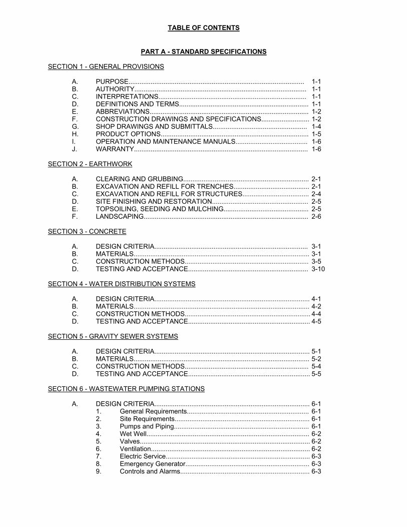
TABLE OF CONTENTS
PART A - STANDARD SPECIFICATIONS SECTION 1 - GENERAL PROVISIONS
A. PURPOSE............................................................................................... 1-1 B. AUTHORITY............................................................................................. 1-1 C. INTERPRETATIONS................................................................................ 1-1 D. DEFINITIONS AND TERMS...................................................................... 1-1 E. ABBREVIATIONS...................................................................................... 1-2 F. CONSTRUCTION DRAWINGS AND SPECIFICATIONS.......................... 1-2 G. SHOP DRAWINGS AND SUBMITTALS................................................... 1-4 H. PRODUCT OPTIONS................................................................................ 1-5 I. OPERATION AND MAINTENANCE MANUALS....................................... 1-6 J. WARRANTY.............................................................................................. 1-6
SECTION 2 - EARTHWORK
A. CLEARING AND GRUBBING.................................................................... 2-1 B. EXCAVATION AND REFILL FOR TRENCHES......................................... 2-1 C. EXCAVATION AND REFILL FOR STRUCTURES.................................... 2-4 D. SITE FINISHING AND RESTORATION.................................................... 2-5 E. TOPSOILING, SEEDING AND MULCHING.............................................. 2-5 F. LANDSCAPING......................................................................................... 2-6
SECTION 3 - CONCRETE
A. DESIGN CRITERIA................................................................................... 3-1 B. MATERIALS............................................................................................... 3-1 C. CONSTRUCTION METHODS................................................................... 3-5 D. TESTING AND ACCEPTANCE................................................................. 3-10
SECTION 4 - WATER DISTRIBUTION SYSTEMS
A. DESIGN CRITERIA.................................................................................... 4-1 B. MATERIALS............................................................................................... 4-2 C. CONSTRUCTION METHODS.................................................................... 4-4 D. TESTING AND ACCEPTANCE.................................................................. 4-5
SECTION 5 - GRAVITY SEWER SYSTEMS
A. DESIGN CRITERIA.................................................................................... 5-1 B. MATERIALS............................................................................................... 5-2 C. CONSTRUCTION METHODS................................................................... 5-4 D. TESTING AND ACCEPTANCE.................................................................. 5-5
SECTION 6 - WASTEWATER PUMPING STATIONS
A. DESIGN CRITERIA.................................................................................... 6-1 1. General Requirements.................................................................. 6-1 2. Site Requirements......................................................................... 6-1 3. Pumps and Piping......................................................................... 6-1 4. Wet Well........................................................................................ 6-2 5. Valves............................................................................................ 6-2 6. Ventilation...................................................................................... 6-2 7. Electric Service.............................................................................. 6-3 8. Emergency Generator................................................................... 6-3 9. Controls and Alarms...................................................................... 6-3
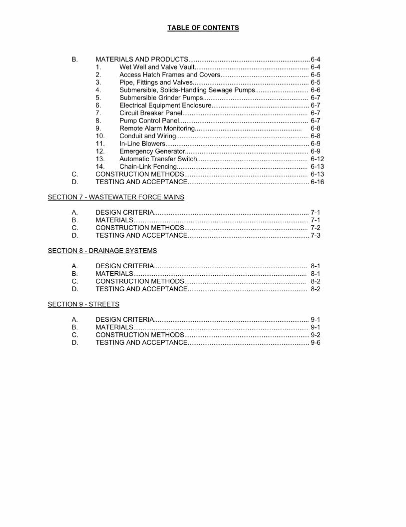
TABLE OF CONTENTS
B. MATERIALS AND PRODUCTS.................................................................. 6-4
1. Wet Well and Valve Vault.............................................................. 6-4 2. Access Hatch Frames and Covers................................................ 6-5 3. Pipe, Fittings and Valves............................................................... 6-5 4. Submersible, Solids-Handling Sewage Pumps............................. 6-6 5. Submersible Grinder Pumps......................................................... 6-7 6. Electrical Equipment Enclosure..................................................... 6-7 7. Circuit Breaker Panel.................................................................... 6-7 8. Pump Control Panel...................................................................... 6-7 9. Remote Alarm Monitoring.......................................................... 6-8 10. Conduit and Wiring........................................................................ 6-8 11. In-Line Blowers.............................................................................. 6-9 12. Emergency Generator................................................................... 6-9 13. Automatic Transfer Switch............................................................ 6-12 14. Chain-Link Fencing....................................................................... 6-13
C. CONSTRUCTION METHODS................................................................... 6-13 D. TESTING AND ACCEPTANCE.................................................................. 6-16
SECTION 7 - WASTEWATER FORCE MAINS
A. DESIGN CRITERIA.................................................................................... 7-1 B. MATERIALS............................................................................................... 7-1 C. CONSTRUCTION METHODS................................................................... 7-2 D. TESTING AND ACCEPTANCE.................................................................. 7-3
SECTION 8 - DRAINAGE SYSTEMS
A. DESIGN CRITERIA................................................................................... 8-1 B. MATERIALS.............................................................................................. 8-1 C. CONSTRUCTION METHODS.................................................................. 8-2 D. TESTING AND ACCEPTANCE................................................................. 8-2
SECTION 9 - STREETS
A. DESIGN CRITERIA.................................................................................... 9-1 B. MATERIALS............................................................................................... 9-1 C. CONSTRUCTION METHODS.................................................................... 9-2 D. TESTING AND ACCEPTANCE.................................................................. 9-6
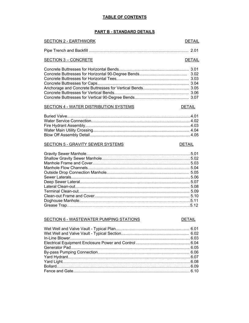
TABLE OF CONTENTS
PART B - STANDARD DETAILS SECTION 2 - EARTHWORK DETAIL
Pipe Trench and Backfill ........................................................................................ 2.01 SECTION 3 – CONCRETE DETAIL
Concrete Buttresses for Horizontal Bends.............................................................. 3.01 Concrete Buttresses for Horizontal 90-Degree Bends.......................................... 3.02 Concrete Buttresses for Horizontal Tees................................................................ 3.03 Concrete Buttresses for Caps................................................................................. 3.04 Anchorage and Concrete Buttresses for Vertical Bends......................................... 3.05 Concrete Buttresses for Vertical Bends.................................................................. 3.06 Concrete Buttresses for Vertical 90-Degree Bends................................................ 3.07
SECTION 4 - WATER DISTRIBUTION SYSTEMS DETAIL
Buried Valve............................................................................................................. 4.01 Water Service Connection....................................................................................... 4.02 Fire Hydrant Assembly............................................................................................. 4.03 Water Main Utility Crossing..................................................................................... 4.04 Blow Off Assembly Detail ......................................................................................... 4.05
SECTION 5 - GRAVITY SEWER SYSTEMS DETAIL
Gravity Sewer Manhole............................................................................................ 5.01 Shallow Gravity Sewer Manhole.............................................................................. 5.02 Manhole Frame and Cover...................................................................................... 5.03 Manhole Flow Channels.......................................................................................... 5.04 Outside Drop Connection Manhole......................................................................... 5.05 Sewer Laterals......................................................................................................... 5.06 Deep Sewer Lateral................................................................................................. 5.07 Lateral Clean-out..................................................................................................... 5.08 Terminal Clean-out.................................................................................................. 5.09 Clean-out Frame and Cover.................................................................................... 5.10 Doghouse Manhole……………………………………………………………………….5.11 Grease Trap……………………………………………………………………………….5.12
SECTION 6 - WASTEWATER PUMPING STATIONS DETAIL Wet Well and Valve Vault - Typical Plan................................................................. 6.01 Wet Well and Valve Vault - Typical Section............................................................ 6.02 In-Line Blower.......................................................................................................... 6.03 Electrical Equipment Enclosure Power and Control ................................................ 6.04 Generator Pad......................................................................................................... 6.05 By-pass Pumping Connection................................................................................. 6.06 Yard Hydrant............................................................................................................ 6.07 Yard Light................................................................................................................. 6.08 Bollard...................................................................................................................... 6.09 Fence and Gate....................................................................................................... 6.10

TABLE OF CONTENTS
SECTION 7 - WASTEWATER FORCE MAINS DETAIL
Sewage Air Valve Manhole ...................................................................................... 7.01 Chemical Injection Manhole ..................................................................................... 7.02 Forcemain Discharge Manhole ................................................................................ 7.03 Buried Valve ........................................................................................................... 7.04
Section 1 - General Provisions Page 1-1
SECTION 1 - GENERAL PROVISIONS
A. PURPOSE
1. The purpose of these Standard Specifications and Details for Utilities Design and Construction is to set forth the minimum requirements of the Town of Millsboro, Delaware, for the planning, design, construction and acceptance of water systems, wastewater systems, storm water systems, and streets constructed within the Town of Millsboro.
2. These Standard Specifications and Details shall be used, when applicable, in conjunction
with Sewers, Chapter 161, Streets and Sidewalks, Chapter 174, Subdivision of Land, Chapter 178, Water, Chapter 206, and Zoning, Chapter 210, from the Code of the Town of Millsboro.
B. AUTHORITY
1. The authority for these Standard Specifications is set forth in The Millsboro Town Charter, adopted as Chapter 457, Volume 60, of the Laws of Delaware.
C. INTERPRETATIONS
1. The provisions of these Standard Specifications shall be held to be minimum requirements. Where these Standard Specifications impose a greater restriction than is imposed or required by other provisions of law or by other rules or regulations or resolutions, the provisions of these Standard Specifications shall control.
2. Where other laws, rules, regulations or resolutions require greater restrictions than are
imposed by these Standard Specifications, the provisions of such other laws, rules, regulations or resolutions shall control.
3. For the purpose of these Standard Specifications, the word “shall” is mandatory and not
discretionary. The word ”may” is permissive. D. DEFINITIONS AND TERMS
1. Contractor - Any individual or firm performing construction work governed by these Standard Specifications.
2. Developer - Any individual, firm, association, syndicate, copartnership, corporation,
trust or any other legal entity commencing proceedings to affect development or subdivision of land for himself or for another.
3. EDU - Equivalent Dwelling Unit. An estimate of the average daily water
consumption by a single-family dwelling unit. For all development within the Town of Millsboro, 1 EDU shall equal 240 gallons per day.
4. Engineer - The individual, firm or association designated by the Town of Millsboro to
provide professional engineering and construction review and administration services for the Town.
5. Street - Any avenue, boulevard, road, lane, parkway, viaduct, alley or other way
open to public travel and which is an existing state or municipal roadway for public use. A street shall include the land between the street lines, whether improved or unimproved, and may comprise pavement, shoulders, gutters, sidewalks, parking areas and other areas within the street lines.
6. Town - The Town of Millsboro, Delaware.
Section 1 - General Provisions Page 1-2
E. ABBREVIATIONS
1. ACI - The American Concrete Institute
2. ANSI - The American National Standards Institute
3. ASA - The American Standards Association
4. ASTM - The American Society of Testing and Materials
5. AWWA - The American Water Works Association
6. AASHTO - The American Association of State and Highway Transportation Officials
7. DelDOT - Delaware Department of Transportation
8. GPD - Gallons per Day
9. GPM - Gallons per Minute
10. NEC - The National Electrical Code
11. OSHA - The Occupational Safety and Health Administration F. CONSTRUCTION DRAWINGS AND SPECIFICATIONS
1. Construction drawings and specifications shall be prepared to show in detail the proposed utility services and other required improvements for the subdivision and development of land in accordance with Chapter 178, of the Code of the Town of Millsboro.
2. The drawing sheet size shall be 24 x 36 inches. The drawing title block shall identify the
project and be consistent on each drawing sheet. All drawings shall be signed and sealed by the responsible Delaware registered professional engineer.
3. The drawings shall include, but not be limited to the following:
a. Title Sheet
i. Project title ii. Project phase, if applicable iii. Date iv. Developer’s name and address v. Design engineer’s name and address vi. Sheet index vii. Location map viii. Developer’s certification approving the drawings ix. Design engineer’s certification as to accuracy x. Design engineer’s seal and signature xi. Approval block for Town official signature and date
b. Street Plans
i. Scale, date and north arrow ii. Horizontal scale of 1 inch = 50 feet or larger iii. Locations, elevations and datum of all project bench marks iv. Survey references and horizontal control points v. Centerline stationing vi. Bearings of centerline tangents vii. Centerline curve data viii. Stations of intersecting roadsExisting and proposed contour lines at 1-foot
Section 1 - General Provisions Page 1-3
intervals ix. All existing and proposed utilities x. Locations and identification of all drainage structures and storm sewers xi. Locations and elevations of parallel swales at 50-foot intervals xii. Drainage flow arrows
c. Street Profiles
i. Drawn at the same horizontal scale as the plans ii. Vertical scale of 1 inch = 5 feet or larger iii. Preferably on the same sheet as the horizontal street plan iv. Centerline stationing v. Existing and proposed grade at centerline vi. Vertical curve data vii. Size, length and slope of storm sewers viii. Invert elevations of storm sewers at drainage structures ix. All existing and proposed utilities
d. Street Sections and Details
i. Typical detail for each major change of section ii. Width of street and shoulders iii. Point of grade iv. Depths and types of pavement materials v. Cross slopes of pavement, shoulders and swales vi. Type of curb vii. Sidewalk viii. Intersection details ix. Typical lot and driveway details x. Locations of topsoil, seed and mulch
e. Buried Pipe Plans
i. Scale, date and north arrow ii. Horizontal plans drawn at a scale of 1 inch = 50 feet or larger iii. Legend to identify existing and proposed features iv. Locations, elevations and datum of all project bench marks v. Centerline stationing vi. Existing and proposed contour lines vii. Locations of all existing utilities and structures viii. Property lines ix. Existing and proposed easements
f. Buried Pipe Profiles
i. Drawn at the same horizontal scale as the plans ii. Vertical scale of 1 inch = 5 feet or larger iii. Centerline stationing iv. Existing and proposed grade at centerline v. Invert elevations at all structures and inflection points vi. All existing and proposed utilities vii. For storm drain pipe, 10-year HGL
g. Landscaping Plans
i. Scale, date and north arrow ii. Planting section table iii. Site plan drawn at a scale of 1 inch = 50 feet or larger iv. Existing and proposed trees, shrubs & landscaping features v. Planting sequence, details and installation notes.
Section 1 - General Provisions Page 1-4
h. Lighting Plans i. Scale, date, and north arrow ii. Luminaire Schedule including height, wattage, and lamp type iii. Site plan showing photometric data and location of all proposed luminaires iv. Pole specification including height, spacing, and foundation details
a. Sediment and storm water management plans and details shall be in accordance
with the Delaware Erosion and Sediment Control Handbook and Sussex Conservation District requirements.
b. Detail sheets shall be included as necessary for construction in addition to the
details included in these Standard Specifications. G. SHOP DRAWINGS AND SUBMITTALS
1. The Contractor shall submit shop drawings and other submittals as required by these Standard Specifications and the project specific requirements, to afford the Town, the opportunity to review the intended equipment, materials, installation and/or construction methods and other aspects of the project prior to the ordering, fabrication, installation, and/or construction of the work. This review function is to serve the Town's interest, and does not in any way, modify or affect the Contractor's responsibility to fully satisfy the requirements of these Standard Specifications and the approved project construction plans and specifications.
2. The Contractor warrants that the Town's review of the shop drawings and other submittals
and any notations issued as part of that review, do not relieve the Contractor from full compliance with the requirements of these Standard Specifications and the approved project construction plans and specifications. The Contractor will be solely responsible for confirming and coordinating the quantities, dimensions, adjacent and related work, fabrication process, installation methods, construction methods, and all other requirements of the work. The Contractor is solely responsible for initiating, maintaining, and supervising all safety precautions and programs in connection with the work.
3. Two (2) hard copies of each shop drawing and submittal shall be provided. An electronic
copy shall also be provided. An electronic copy will be returned to the Contractor after the Engineer's review. If additional reviewed copies are desired by the Contractor, they shall be submitted with the number to be returned indicated on the transmittal letter.
4. Each copy of all shop drawings and submittals shall include a shop drawing certification that includes the following information:
a. Project identification
b. A reference to the specification or drawing description
c. Contractor's certification statement as follows: This shop drawing submission
complies with the requirements of the Contract Documents.
d. The Contractor's name
e. The signature of the Contractor's representative
f. The date of signing
5. Shop drawings and submittals are required for the items listed below, and for any other
Section 1 - General Provisions Page 1-5
items as directed in writing by the Engineer:
a. Pipes, valves, fire hydrants, fittings, and appurtenances
b. Precast concrete structures
c. Concrete mix designs
d. Concrete admixtures
e. Concrete reinforcing steel
f. Manhole frames and covers
g. Pumps and appurtenances
h. Emergency generators, automatic transfer switch, and related equipment
i. Electrical equipment, instrumentation, and controls
j. Lighting fixtures
k. Remote Pump Monitoring and Control Systems
l. Chemical feed equipment
m. HVAC equipment H. PRODUCT OPTIONS
1. Where a particular manufacturer’s product is specified, provide the product named. Substitutions may be considered, unless otherwise indicated.
2. Where a list of manufacturers’ products is specified, provide one of the products named
products. Substitutions may be considered, unless otherwise indicated.
3. Where a product or list of products is specified, including the term “or approved equivalent”, provide one of the products listed or another product that complies with requirements. Submit the following, in addition to other required submittals, to obtain approval of an unnamed product:
a. Evidence that the proposed product will produce the required results, and that it is
compatible with other portions of the work
b. A detailed comparison of significant qualities of the proposed product with the specified product(s)
c. Significant qualities include attributes such as performance, weight, size, materials
of construction, durability and specific features
d. Evidence that proposed product provides an equivalent warranty
e. A list of completed product installations for similar projects with contact names and addresses if requested
f. Samples, if requested

Section 1 - General Provisions Page 1-6
I. OPERATION AND MAINTENANCE MANUALS
1. The Contractor shall provide six (6) copies of manufacturer’s operation and maintenance manual for the items listed below, and for any other items as directed in writing by the Engineer:
a. Pumps
b. Valves
c. Emergency generators
d. Automatic transfer switches
e. Control panels
Remote Pump Monitoring and Control System
f. Chemical feed systems
g. HVAC equipment
2. The manuals shall be provided in suitable binders and include spare parts lists, printed instructions and diagrams required for installation, service, repair or replacement, and the name, address and phone number of agency that will make repair or replacement during warranty period, and/or where spare parts may be obtained.
J. WARRANTY
The Contractor shall warrant that all workmanship, material, and equipment furnished and installed by him shall be free of defects for a period of one (1) year after the acceptance by the Town. In the event that portions of a project are accepted individually, the warranty shall be for one (1) year after each certificate of acceptance. Should such defects appear, the Contractor shall repair or replace such defects at no cost to the Town.
Section 2 - Earthwork Page 2-1
SECTION 2 - EARTHWORK A. CLEARING AND GRUBBING
1. Clearing and grubbing shall consist of clearing, grubbing, stockpiling, removing, and disposing of all vegetation and debris, except such objects as are designated to remain or are to be removed. This work shall also include the preservation from injury or defacement of all vegetation, trees and objects designated to remain and the restoration of those objects designated for preservation that have been injured or defaced.
2. All materials removed by the clearing and grubbing operation shall be disposed of in
accordance with all state and local regulations.
3. Trees, shrubbery, plants, and other objects which are not to be removed shall be protected from damage. If any plants are damaged, they shall be either replaced or repaired by the Contractor or by a competent tree surgeon. Paint required for cut or scarred surfaces of trees or shrubs selected for retention shall be asphaltum base paint prepared specifically for tree surgery.
4. Grading operations shall not be started in any area until all the operations of clearing and
grubbing within the area affected have been completed. In areas where excavation is to be made, the ground shall be cleared of all living or dead trees, stumps, brush, or other objectionable materials. All stumps, root mats, etc., shall be removed to a depth of 2 feet below the subgrade or slope surfaces. All depressions made below the subgrade or slope surfaces by the removal of stumps or roots shall be backfilled with approved material and compacted as directed.
B. EXCAVATION AND BACKFILL FOR TRENCHES
1. This item includes all excavation and backfilling. The Contractor shall provide all labor and materials required for the excavation and backfill of utility trenches, including but not limited to sheeting, shoring, sheet piling, and bracing; pumping or other approved methods to keep excavations free of water and other liquids; accommodation of sewage and drainage flows; support and protection of utilities and other structures encountered in the work; furnishing and maintaining adequate barricades, warning signs, lights, and other means of protecting the public; disposal of surplus excavated materials and the restoration of the site. All excavations shall be in accordance with OSHA guidelines. Braced excavations shall be designed by a Delaware registered professional engineer.
2. The trench subgrade shall provide uniform and continuous bearing and support on solid
undisturbed earth for the full length of each pipe, except for that portion of the bell hole. Any part of the bottom of the trench excavated below the specified subgrade shall be corrected with approved material and thoroughly compacted. Where the bottom of the trench excavation is unstable or unsuitable material is present, including ASTM Class IV and Class V material, the excavation shall be carried to such depth as directed by the Engineer. The trench bottom shall be restored to subgrade with stone bedding.
3. Bell-holes shall be excavated in the bottom and sides of trenches to permit the proper
installation of pipe joints.
4. The sides and ends of all excavations or structures shall be supported, when necessary, with soldier piles and lagging, sheeting and shoring, trench boxes, etc. to maintain a stable excavation and prevent damage to adjacent public and private property.
5. All excavation bracing shall be removed as trench backfilling is completed, except where
and to such extent as the Town’s Engineer directs the Contractor to leave the shoring in
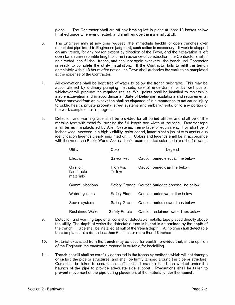
Section 2 - Earthwork Page 2-2
place. The Contractor shall cut off any bracing left in place at least 18 inches below finished grade wherever directed, and shall remove the material cut off.
6. The Engineer may at any time request the immediate backfill of open trenches over
completed pipeline, if in Engineer's judgment, such action is necessary. If work is stopped on any trench, for any reason except by direction of the Town, and the excavation is left open for an unreasonable length of time in advance of construction, the Contractor shall, if so directed, backfill the trench, and shall not again excavate the trench until Contractor is ready to complete the utility installation.. If the Contractor fails to refill the trench completely within 48 hours after notice, the Town shall authorize the work to be completed at the expense of the Contractor.
7. All excavations shall be kept free of water to below the trench subgrade. This may be
accomplished by ordinary pumping methods, use of underdrains, or by well points, whichever will produce the required results. Well points shall be installed to maintain a stable excavation and in accordance all State of Delaware regulations and requirements. Water removed from an excavation shall be disposed of in a manner as to not cause injury to public health, private property, street systems and embankments, or to any portion of the work completed or in progress.
8. Detection and warning tape shall be provided for all buried utilities and shall be of the
metallic type with metal foil running the full length and width of the tape. Detector tape shall be as manufactured by Allen Systems, Terra-Tape or equivalent. Foil shall be 6 inches wide, encased in a high visibility, color coded, insert plastic jacket with continuous identification legends clearly imprinted on it. Colors and legends shall be in accordance with the American Public Works Association's recommended color code and the following:
Utility Color Legend
Electric Safety Red Caution buried electric line below
Gas, oil, High Vis. Caution buried gas line below flammable Yellow materials
Communications Safety Orange Caution buried telephone line below
Water systems Safety Blue Caution buried water line below
Sewer systems Safety Green Caution buried sewer lines below
Reclaimed Water Safety Purple Caution reclaimed water lines below
9. Detection and warning tape shall consist of detectable metallic tape placed directly above the utility. The depth at which the detectable tape is buried is determined by the depth of the trench. Tape shall be installed at half of the trench depth. At no time shall detectable tape be placed at a depth less than 6 inches or more than 36 inches
10. Material excavated from the trench may be used for backfill, provided that, in the opinion
of the Engineer, the excavated material is suitable for backfilling.
11. Trench backfill shall be carefully deposited in the trench by methods which will not damage or disturb the pipe or structures, and shall be firmly tamped around the pipe or structure. Care shall be taken to assure that sufficient soil material has been worked under the haunch of the pipe to provide adequate side support. Precautions shall be taken to prevent movement of the pipe during placement of the material under the haunch.

Section 2 - Earthwork Page 2-3
12. The trench shall be refilled in 8-inch compacted layers. All compaction of material from the bottom of the trench to the spring line of the pipe shall be done by pneumatic hand tampers; or if the material is composed largely of coarse aggregate, the use of other hand tampers may be required, .
13. The moisture content of the material being compacted shall be within plus or minus three
(+/-3) percentage points of optimum, as determined by ASTM D 1557. Material containing an excess of moisture shall be processed and dried, or permitted to dry until the moisture content is within the specified range. The processing shall include removal of large rocks, root matter and other foreign material prior to use as backfill. Material which is too dry shall be wetted until the moisture content is within the specified range.
14. Each layer of trench backfill under pavement or shoulders, including existing or proposed,
shall be compacted to 95 percent or more of the maximum density, as determined by ASTM D 1557. Backfill not under existing or proposed pavement or shoulders shall be compacted to 90 percent or more of the maximum density, as determined by ASTM D 1557.
15. Testing of the compaction of fill shall be performed by the Contractor testing agency,
Copies of the test results shall be provided to the Town. The Town’s Engineer may perform in-place density testing during trench backfill and compaction, or upon completion of the backfill operations. If the results of any tests show that backfill does not meet the specified compaction requirements, the Contractor shall correct the condition in such portions of the trench represented by the unsatisfactory test results.
16. Backfill of all excavations not in paved areas shall be restored to the condition that existed
prior to beginning work, and maintained for a period of 12 months following the date of acceptance.
17. The Contractor shall maintain all backfilled excavations. The trench surfaces shall be
reshaped where necessary. All depressions developing following excavation and backfill shall be properly refilled. If the Contractor fails to make repairs within 48 hours after receipt of written notice from the Town, the Town may backfill the depression or install temporary protection and signage without notice to the Contractor, and the cost of so doing shall be paid by the Contractor.
18. The Contractor shall be responsible for any injury or damage that may result from lack of
maintenance of backfilled excavations at any time prior to the date of final acceptance.
19. After completion of backfilling, all unused material shall be removed and properly disposed of by the Contractor in accordance with current regulatory requirements and contract requirements. All roads, sidewalks, and other places within the project boundaries shall be left clean and in good order.
C. EXCAVATION AND REFILL FOR STRUCTURES
1. The Contractor shall perform all excavation, refill, and filling, and shall provide all fill material required for the construction of structures including but not limited to sheeting, shoring, sheet piling, and bracing; pumping or other approved methods to keep excavations free of water and other liquids; accommodation of sewage and drainage flows; support and protection of utilities and other structures encountered in the work; furnishing and maintaining adequate barricades, fencing, warning signs, lights, and other means of protecting the public; disposal of surplus excavated materials and the restoration of the site.
2. Where structure or structure footings are to bear on material other than rock or piles, care shall be taken so as not to disturb the bottom of the excavation. After each excavation is completed, the Contractor shall proof-roll the subgrade in the presence of the Engineer.
Section 2 - Earthwork Page 2-4
No stone bedding, steel reinforcement, or concrete shall be placed until the Engineer has reviewed the proof-rolling and the condition of the subgrade.
3. The Contractor shall be required to maintain structure excavations dewatered during
construction activities by such methods as the Contractor deems necessary. This may be accomplished by ordinary pumping methods, use of underdrains, or by well points, whichever will produce the required results. Well points shall be installed in accordance all State of Delaware regulations and requirements. Water removed from an excavation shall be disposed of in a manner as to not cause injury to public health, private property, street systems and embankments, or to any portion of the work completed or in progress.
4. The Contractor shall support the sides and ends of all excavations and structures shall
be supported, when necessary, with soldier piles and lagging, sheeting and shoring, trench boxes, etc. to maintain a stable excavation and prevent damage to adjacent public and private property Braced excavation shall be designed by a Delaware registered professional engineer.
5. All excavation bracing shall be removed as trench backfill is completed, except where and
to such extent as the Town’s Engineer directs the Contractor to leave the shoring in place. The Contractor shall cut off any bracing left in place at least 18 inches below finished grade wherever directed, and shall remove the material cut off.
6. Excavated material may be used for backfill provided that, in the opinion of the Engineer,
the excavated material is suitable.
7. All excavated material not required or suitable for backfill or other designated purposes shall be removed from within the limits of the work and disposed of by the Contractor.
8. No backfill shall be placed against any new concrete or masonry structure until all of the
provisions for curing, dampproofing, and/or waterproofing have been complied with, and until the compression strength testing of concrete cylinders prepared during concrete placement indicate that the concrete has obtained the desired compressive strength. Concrete compressive strength test results shall be provided to the Town for their review.
9. Backfill material shall be placed in uniform layers not more than 8 inches thick. Each layer
shall be uniformly compacted to 95 percent or more of the maximum density, as determined by ASTM D 1557, before the next layer is placed. The placement and compaction of backfill material shall be monitored and testing by the Contractor’s testing agency. Daily field reports, include observations and test results shall be provided to the Town for their review.
10. The moisture content of the material being compacted shall be within plus or minus three
(+/-3) percentage points of optimum, as determined by ASTM D 1557. Material containing an excess of moisture shall be processed and dried, or permitted to dry until the moisture content is within the specified range. Material which is too dry shall be wetted until the moisture content is within the specified range.
11. The Engineer may perform in-place density testing during backfill placement and
compaction or upon completion of the backfill operations. If the results of any tests show that backfill does not meet the specified compaction requirements, the Contractor shall correct the condition.
12. Backfill of all excavations not in paved areas shall be restored to the condition that existed
prior to beginning work, and maintained for a period of 12 months following the date of final acceptance.
13. The Contractor shall maintain all backfilled excavations. All depressions developing
following excavation backfill shall be properly refilled. If the Contractor fails to make
Section 2 - Earthwork Page 2-5
repairs within 48 hours after receipt of written notice from the Town, the Town may backfill the depression or install temporary protection and signage without previous notice to the Contractor, and the cost of so doing shall be paid by the Contractor.
14. The Contractor shall be responsible for any injury or damage that may result from lack of
maintenance of backfilled excavations at any time prior to the date of final acceptance.
15. After completion of backfilling, all unused material shall be removed and properly disposed of by the Contractor in accordance with current regulatory requirements and contract requirements. All roads, sidewalks, and other places within the project boundaries shall be left clean and in good order. .
D. SITE FINISHING AND RESTORATION
1. Non-paved areas disturbed by the construction shall be topsoiled, seeded, and mulched.
2. Excavation shall be carried to acceptable lines, grades, and slopes as indicated in the contract drawings. All earth slopes shall be finished to neat, regular lines.
3. For pipeline construction, the restoration of unpaved areas shall be accomplished at a
uniform rate closely following installation of the pipeline. The area shall be neatly dressed within 1 week following backfilling operations and when the soil has consolidated after a period of time, the area shall be again dressed or permanently restored. Surface restoration shall be completed within 15 days after the installation of the pipeline.
4. The Contractor shall install and maintain erosion sediment controls to prevent the erosion
of freshly-graded areas during construction and restoration. All sedimentation and erosion control measures shall be in accordance with the Delaware Erosion & Sediment Control Handbook, latest edition.
5. The Contractor shall maintain restoration work for a period of 12 months after final
acceptance. Maintenance of the restoration shall include all labor, equipment, material, and supplies necessary, including trench refill and additional topsoil, seeding, mulching, watering, and erosion protection.
E. TOPSOILING, SEEDING AND MULCHING
1. All disturbed areas not specified to be paved shall be topsoiled to a depth of 4 inches, seeded and mulched.
2. Before placing or depositing topsoil, the subgrade shall be approved by the Engineer. The
topsoil shall be placed in reasonably close conformity to the desired lines, grades, and elevations.
3. Seeding shall consist of preparing the ground and furnishing and placing all lime, fertilizer,
and seed on the areas to be seeded. Seeding shall not be done during windy weather or when the ground is frozen, excessively wet, or otherwise untillable. The Engineer reserves the right to stop seeding operations whenever conditions are determined to be unfavorable.
4. The area to be seeded shall be thoroughly loosened to a depth of 6 inches, and if just prior
to seeding, the top 3 inches of soil is loose, friable, and free of large clods, rock, or other extraneous matter 1 inch or more in diameter, measured at the widest dimension; and if shaped to the prescribed grade, it shall be a satisfactory seedbed and require no further work. However, when the area to be seeded is partially sodded, barren, weedy, or packed and hard, any grass and weeds shall first be cut or otherwise satisfactorily removed; and the soil shall then be scarified or otherwise loosened to a depth of 4 inches. Clods and lumps shall be broken, rubbish, rocks, and other extraneous matter removed clear of the site; and
Section 2 - Earthwork Page 2-6
the upper 3 inches shall be disked or otherwise worked into a satisfactory seedbed.
5. Limestone shall be applied at the rate of 3,000 pounds/acre. Fertilizer shall be applied according to the quantities of actual plant food/acre required for the seed mix.
6. The seeded area shall be mulched at a rate of 90 pounds per 1,000 square feet with either
wood cellulose fiber mulch or straw mulch. A chemical mulch binder shall be used at the rate of 60 gallons/acre. Asphaltic-base binder shall not be permitted.
7. The following maintenance procedure shall be followed prior to acceptance:
a. Maintain surfaces and supply additional topsoil where necessary including areas
affected by erosion.
b. Water to ensure uniform seed germination and to keep surface of soil damp.
c. Apply water slowly so that surface of soil will not puddle and crust.
d. Cut newly-planted grass for the first time when it reaches a height of 2-1/2 inches and maintain a minimum height of 2 inches. Do not cut more than 1/3 of the blade at any mowing. Remove clippings.
e. After the first mowing, water grass sufficiently to moisten the soil from 3 inches to 5
inches deep.
f. Apply weed killer, if weeds start developing, during calm weather when air temperature is above 50 degrees.
g. Replant damaged grass areas showing root growth failure, deterioration, bare or
thin spots and eroded areas.
8. Seeded areas will be accepted at the end of maintenance period when seed areas are properly established and otherwise acceptable.
F. LANDSCAPING
1. Replacement small trees and shrubs shall be furnished and installed in kind in the event that existing plants which are to remain are damaged beyond repair.
2. The Contractor shall backfill all areas following removal of trees and stumps, specifically
designated for complete removal for the proper installation of facilities.
3. Tree removal shall include but not be limited to the removal of all roots and organic material to a depth of 18 inches below the surface. Blasting shall not be permitted as a method of removal. The excavated area shall be backfilled with select granular material.
4. All precautions customary in good trade practice shall be taken in preparing plants for
transplanting. Plants transplanted with workmanship that fails to meet the highest standards will be rejected. All plants shall have firm, natural balls of earth of ample proportions and diameter as specified in the "USA Standard for Nursery Stock". Plants with cracked, broken, or crushed balls which occur either before or during planting operations, will be rejected and shall be removed from the site immediately. Bare root plants shall be dug with sufficient spread and depth of roots as to insure full and prompt recovery and development of the plants. All plants shall be handled so that roots are adequately protected and moist at all times. Material that cannot be planted immediately after delivery shall be adequately protected by covering with canvas, wet straw, burlap, moss, or other suitable material and kept covered until ready to be planted. Trees shall not be planted with frozen earth balls.

Section 2 - Earthwork Page 2-7
5. In all mass plant areas, the plants shall be evenly spaced to give uniform cover in the planting bed area. No excavation shall commence until all locations are approved.
6. All trees and shrubs shall be planted in pits excavated with vertical sides. They shall be of
such a depth that when planted and settled, the crown of the plant shall bear the same relation to finished grade as it did to soil surface in its place of growth. All backfill topsoil shall be covered with waterproof material after mixing. Pits shall be backfilled with specified soil mix and compacted firmly, especially under ball of roots to establish a firm foundation. Plants shall be set in the center of pits in a vertical position so that the crown of the plant is level with the finished grade after allowing for watering and settling of soil. The soil mixture shall be carefully and firmly worked and tamped under and around the base of the ball to fill all voids. When partially backfilled and compacted, the burlap shall be removed from the sides and tops of the balls and cut away to prevent air pockets, but no burlap shall be pulled from under the balls. A ring of earth shall be formed around the plant to produce a dish for watering. All plants shall be thoroughly watered immediately after planting. This shall mean complete saturation of all backfill in the pits and beds during the same day of planting. Care shall be taken during all planting operations to insure that no excavated material is dumped on any grassed area unless a suitable type of matting or protective underlay is used.
7. Trees and shrubs shall be watered as necessary to maintain the plantings until established.
8. Trees, shrubs, and ground cover shall be mulched with a 2 inch cover of mulch. Mulch shall be placed the same day of planting. All trees shall be wrapped with the wrapping material overlapping 1-1/2 inches from the lowest main branches to the base of the tree. The wrapping shall be tied at the top and bottom, and at 1 foot intervals along the trunk with twine.
9. Upon the completion of the restoration of surfaces, final cleaning shall be done within the
limits of the project, and shall consist of completely cleaning the project of excess material, sweeping pavements and structures of dirt and rubbish, and the removal of any unused material which will mar the appearance of the project.
Section 3 - Concrete Page 3-1
SECTION 3 - CONCRETE A. DESIGN CRITERIA
1. Concrete in direct contact with sewage shall be 4,000 psi, Class B in accordance with Subsection B - MATERIALS, below. Concrete not in direct contact with sewage shall be 3,000 psi, Class C.
2. Concrete shall conform to all provisions of the "Specifications for Structural Concrete for
Buildings", ACI 301, as published by the American Concrete Institute, except as modified herein.
3. Concrete shall conform to all provisions of the latest edition of the following publications
which shall be incorporated as part of these Standard Specifications:
a. ACI 304 Recommended Practice for Measuring, Mixing, Transporting, and Placing Concrete
b. ACI 305 Recommended Practice for Hot Weather Concreting c. ACI 306 Recommended Practice for Cold Weather Concreting d. ACI 315 Manual of Standard Practice for Detailing Reinforced Concrete
Structures e. ACI 318 Building Code Requirements for Reinforced Concrete f. ACI 347 Recommended Practice for Concrete Formwork i. ACI 350 Code Requirements for Environmental Engineering Concrete
Structures and Commentary g. ACI 525 Minimum Requirements for Thin-Section Precast Concrete
Construction h. ASTM C31 Method of Making and Curing Concrete Test Specimens in the
Field i. ASTM C33 Specification for Concrete Aggregate j. ASTM C39 Test Method for Compressive Strength of Cylindrical Concrete
Specimens k. ASTM C138 Test for Weight per Cubic Foot, Yield and Air Content
(Gravimetric) of Concrete l. ASTM C143 Test Method for Slump of Portland Cement Concrete m. ASTM C150 Specification for Portland Cement n. ASTM C172 Method of Sampling Freshly Mixed Concrete o. ASTM C173 Test for Air Content of Freshly Mixed Concrete by the Volumetric
Method p. ASTM C231 Test Method for Air Content of Freshly Mixed Concrete by
Pressure Method q. ASTM C685 Specification for Concrete Made by Volumetric Batching and
Continuous Mixing r. AWS B3.0 Standard Qualification Procedure s. AWS D1.0 Code for Welding in Building Construction t. AWS D1.1 Recommended Practice for Welding Reinforcing Steel, Metal u. CRSI 65 Recommended Practice for Placing Bar Support
B. MATERIALS
1. Portland Cement Concrete
a. Portland cement concrete shall be composed of Portland cement, fine aggregate, coarse aggregate, admixtures and water, prepared and constructed in accordance with these Standard Specifications.

Section 3 - Concrete Page 3-2
b. The composition of the mix and strength requirements as established by ASTM C94 shall conform to the following:
Class of Concrete: A B C Min. 28-Day Compr. Strength (PSI) 4500 4000 3000 Cement Content:
Minimum Sacks/CY 7-1/2 7 6 Minimum Pounds/CY 705 658 564 Water Cement Ratio 0.45 0.45 0.45
Slump (Inches) 2-4 2-4 2-4
c. Proportions shall provide proper strength, placeability, and durability.
d. Required or permitted admixtures shall be incorporated according to manufacturer's directions.
e. All concrete exposed to weather and unheated areas shall contain 4% to 6%
entrained air as indicated in Chapter 3, ACI 301. Use an air entraining admixture and normal Portland cement or an air entraining Portland cement. Measure air content at point of discharge at job site.
2. Cement
a. Cement for all concrete not in direct contact with sewage shall be Portland Gray Cement conforming to ASTM C150, Type I or Type IA. Only one brand of any one type shall be used for exposed surfaces.
b. Cement for all concrete in direct contact with sewage (even if coated) may be the
same as above except the C3A content shall be less than 8 percent. Portland blast furnace slag cement (ASTM C595), Type IS (MS) or IS-A (MS) also may be used as well as Portland Pozzolan Cement (ASTM C 595). Types IP or IPA, with pozzolan content not exceeding 25 percent by weight.
3. Aggregates
a. Fine aggregate for use in concrete shall be in accordance with ASTM C33, except
Section 4.2 therein does not apply, and shall be graded as follows:
Sieve Size Percent Passing
3/8 inch 100 No. 4 95 - 100
No. 16 50 - 85 No. 50 10 - 30 No. 100 2 - 10
b. Coarse aggregate shall be hard, durable, uncoated, crushed stone or gravel
conforming to ASTM C33. Maximum size of aggregate shall not exceed 3/4 inch. Coarse aggregate for concrete in sewage and other liquid containing structures shall conform to ASTM C33 except the following limitations shall apply:
i. Soft particles: 20 percent
Section 3 - Concrete Page 3-3
ii. Chert as a soft impurity: 1.0 percent iii. Total of soft articles and chert as a soft impurity: 2.0 percent iv. Flat and elongated particles long dimension more than 5 times short
dimension: 15.0 percent.
Size 3/4 inch to No. 4 (ASTM No. 67)
Sieve Size Percent Passing
1 inch 100 3/4 inch 90 - 100 3/8 inch 20 - 55 No. 4 0 - 10
4. Concrete Admixtures
a. Calcium chloride shall not be permitted as an admixture.
b. Admixtures for air entrainment shall conform to ASTM C260 and shall be AER as
manufactured by SIKA Chemical Corporation, MBOR as manufactured by Master Builders or equivalent.
c. Chemical Admixtures shall conform to ASTM C 494. This specification applies to:
i. Type A - Water-reducing admixtures ii. Type B - Retarding admixtures iii. Type C - Accelerating admixtures iv. Type D - Water-reducing and retarding admixtures v. Type E - Water-reducing and accelerating admixtures
d. Water reducing admixtures shall conform to ASTM C494, and shall be Plastiment
as manufactured by SIKA Chemical Corporation, Pozzolith as manufactured by Master Builders, or equivalent.
5. Water used in mixing, curing, or other designated applications shall be reasonably clean
and free of oil, salt, acid, alkali, sugar, vegetable, or other substance injurious to the finished product. Water shall meet the requirements of ASTM C94. Water known to be of potable quality may be used without test. The water shall have a pH of 4.5 to 8.5.
6. Reinforcing Steel
a. Reinforcement bars shall meet the requirements for Deformed Billet Steel Bars for
Concrete Reinforcement, ASTM A615, Grade 60. Bars shall be free of loose scale, rust, or other coatings that will reduce bond.
b. Accessories include all spacers, chairs, bolsters, ties, other devices necessary for
properly placing, spacing, supporting, and fastening reinforcement in place. Metal accessories shall be galvanized after fabrication or plastic protected where legs will be exposed in finished concrete surfaces. Accessories shall conform to requirements of The Concrete Reinforcing Steel Institute "Manual of Standard Practice of Reinforced Concrete Construction".
c. Wire mesh shall conform to the requirements of ASTM A1064. Wire mesh shall
be fabricated from No. 10 gauge wire conforming to the requirements of ASTM A1064. Individual wires shall be on six inch centers in each direction.
d. Continuous masonry wire reinforcing shall be of truss design, minimum 9 gauge
Section 3 - Concrete Page 3-4
welded steel wire conforming to the requirements of ASTM A1064 with 0.8 oz. hot-dip zinc coating after fabrication in accordance with ASTM A116, Class 3.
e. Wire mesh for reinforcement in concrete pavement construction shall be composed
of cold drawn steel wires meeting the requirements of ASTM A1064.
f. Bar mat reinforcement shall consist of deformed bars conforming to the requirements of ASTM A1064, Intermediate Grade.
7. Concrete Curing Agents
a. Curing compounds shall conform to ASTM C309. The curing compound shall be
compatible with subsequent finished or shall be completely removed. Curing compound shall be Hydrocide Curing Compound by Sonneborne-Contech or equal.
b. Liquid membrane curing compounds shall meet the requirements of AASHTO M
148 for Type 2, Class A or B, White Pigmented. Acceptance for continued use will be based upon satisfactory field performance.
8. Sheet materials used for covering the surface of concrete to inhibit moisture loss during the
curing period shall conform to the requirements of AASHTO M171 for Polyethylene Film and Waterproof Paper. The name of the waterproof paper manufacturer shall be marked or imprinted clearly on the paper for proper identification and it shall retain 90% of the mix water.
9. Mortar sand shall conform to AASHTO M45 and 100 percent of the material shall pass a Number 4 sieve.
10. Rubber Joint Sealant shall be a multipart chemically curing polyurethane sealant which
meets or exceeds the curing requirements of Federal Specification TT-S-00227E (3) and TT-S-00230C (2) Nonsag type, Class A, compounds resistant to 50 percent total joint movement. The color shall be gray to match concrete. A primer shall be used as recommended by the sealant manufacturer. A bond breaker such as masking tape, polyethylene film, or backing rod as supplied by the manufacturer shall be used at the bottom of the joint. The sealant shall be Fox Industries FX-570/571 or equal.
11. Waterstops shall be dumbbell type on horizontal joints and center bulb on vertical joints,
polyvinyl chloride (PVC) compounded as necessary to meet the requirements as manufactured by Greenstreak, or equal. No reclaimed PVC from any source shall be incorporated in the compounding. The extruded material shall be dense, homogeneous, and free from porosity or other imperfections which could affect its durability of performance.
12. Form lumber in contact with exposed concrete shall be new and conform to the following:
a. For concrete exposed to view use plywood with DFPA stamp of "B-B Plyform".
Plyform shall be 5/8" thick for supports 12 inches on center maximum or 3/4" thick for supports 16 inches on center maximum. Use in as large sheets as practical to keep joints to a minimum.
b. For concrete not exposed to view use clean, straight lumber, plywood, or metal.
13. Form oil shall be colorless and non-staining.
14. Form ties used for exposed concrete surfaces shall have a minimum working strength when
fully assembled of at least 3,000 pounds. Ties shall be adjustable in length to permit complete tightening of forms and of such type as to leave no metal closer than 1 1/2" to the surface. Ties shall be factory fabricated, removable, or snap-off ties that will not allow form deflection and will not spall concrete upon removal, fitted with devices that will leave holes
Section 3 - Concrete Page 3-5
in the concrete surface not less than 1/2 inch or more than one inch in diameter and of depth not greater than diameter at the exposed surface.
15. Form snap ties shall have water stops incorporated and be as manufactured by Dayton Sure
Grip, Type 42, or equal with 1 1/2" set back from the face of the wall as detailed in ACI 347.
16. All vapor barriers shall be 10 mil polyethylene.
17. Slots and inserts shall be standard types to engage anchors supplied. Slots shall be dovetail type, 24 gauge galvanized sheet steel minimum with fillers.
18. Grout for base and bearing plates shall be high strength, non-shrink and non-metallic.
19. Expansion joint material shall consist of ½-inch thick pre-formed strips made from clean
granulated cork particles securely bound together by an insoluble synthetic resin. Other types of expansion material may be used when specifically approved by the Town.
C. CONSTRUCTION METHODS
1. The Contractor shall employ a competent foreman for all concrete work. The foreman shall be thoroughly familiar with all phases of concrete construction including materials, formwork, reinforcing, mixing, and placing and protection during the initial period of curing.
2. Formwork
a. Formwork shall be in accordance with Chapter 4, ACI 301.
b. Lay out forms for all required cast-in-place concrete to the shapes, sizes, lines,
and dimensions indicated on the Drawings, and exercise particular care in the layout of forms to avoid necessity for cutting of concrete after it is in place.
c. Make proper provision for all openings, offsets, recesses, anchorage, blocking,
and other features of the work as shown or required; perform all forming required for work of other trades and do all cutting and repairing of forms required to permit such installation; and consult with other trades as required relative to provision for openings, chases, and other items in the forms.
d. Set all required steel frames, angles, grills, bolts, inserts, and other such items
required to be anchored in the concrete before the concrete is placed.
e. Properly brace and tie the forms together so as to maintain position and shape and to ensure safety to personnel; construct all bracing, supporting members, and centering of ample size and strength to safely carry, without excessive deflection, all dead and live loads to which they may be subjected; and properly space the forms apart and securely tie them together, using metal spreader ties that give positive tying and accurate spreading.
f. All forms shall be straight, true, plumb, and square within a tolerance horizontally
of one in 200 and a tolerance vertically of one in 500.
g. Plywood panels shall be nailed directly to studs and applied in a manner to minimize the number of joints. All panel joints shall be tight butt joints with all edges true and square.
h. All footing forms shall be wood unless otherwise specifically approved by the Engineer. Upon approval of the Engineer, side forms for footings may be of earth provided the soil will stand without caving and the sides of the bank are made with a neat cut to the minimum dimensions indicated on the Drawings. The Contractor
Section 3 - Concrete Page 3-6
shall make all necessary provisions to prevent cave-ins during placement of concrete.
i. Reuse of forms shall be subject to advance approval of the Engineer. Reuse of
forms shall in no way delay or change the schedule for placement of concrete from the schedule obtainable if all forms were new. Reuse of forms shall in no way impart less structural stability to the forms nor less acceptable finish to the concrete.
j. In general, side forms of footings may be removed seven (7) days after placement
of concrete, but the time may be extended if deemed necessary by the Engineer.
3. Reinforcement
a. Reinforcement shall be in accordance with Chapter 5, ACI 301.
b. Fabricate all reinforcement in strict accordance with shop drawings which have been reviewed by the Engineer. Bars with kinks or bends not shown on the Drawings or on the reviewed shop drawings shall not be used.
c. Reinforcement shall not be bent or straightened in a manner that will injure the
material. All bars shall be bent cold. Bends for stirrups and ties shall be made around a pin having a diameter not less than two (2) times the minimum thickness of the bar. Bends for the other bars, including hooks, shall be made around a pin having a diameter not less than six (6) times the minimum thickness of the bar.
d. Before the start of concrete placement, accurately place all concrete reinforcement
and positively secure and support by concrete blocks, metal chairs or spacers, or by metal hangers. Clearances shall be as follows:
i. The clear space between bars shall not be less than 1 1/2 times the normal
diameter of round bars. ii. In no case shall the clear distance be less than 1 1/2 inches nor less than
1 1/3 times the maximum size of aggregate. iii. The following minimum concrete covering of reinforcement shall be used:
• Concrete below ground against forms: Two (2) inches • Concrete deposited against earth: Three (3) inches
e. Place bars in horizontal members with minimum laps at splices sufficient to develop
the strength of the bars. Bars may be wired together at laps except at point of support of the member, at which point preserve the clear space described above.
f. Whenever possible, stagger the splices of adjacent bars. Splice 36 bar diameters
minimum.
g. Make all splices in wire fabric at least 1-1/2 meshes wide.
h. All steel dowels shall be anchored into position before the concrete is placed.
4. Joints and Embedded Items
a. Joints and embedded items shall be in accordance with Chapter 6, ACI 301.
b. Construction joints shall be constructed and located so as not to impair the strength of the structure. The location of construction and control joints shall be approved by the Engineer prior to starting concrete placement. Maximum spacing of vertical construction joints shall be thirty (30) feet. All construction joints below liquid levels shall be keyed and waterstopped.
c. At construction joints, erect a temporary wood bulkhead so that the jointing will

Section 3 - Concrete Page 3-7
follow a vertical plane at right angles with the direction of the main reinforcement. To this bulkhead fasten a wood strip 2" thick and of width equal to one-third the depth of the concrete slab to form a tongue and grooved joint.
d. Waterstops shall be installed continuous and shall be welded at butt joints and
intersections in strict accordance with manufacturer's instructions.
e. Slots shall be installed in face of all concrete against which masonry will be installed. Space at 2'-0" on centers horizontally or as required by details and/or job conditions. Slots shall also be installed where masonry will abut concrete.
5. Delivery, Storage and Handling
a. All concrete shall be ready mixed and transported in accordance with ASTM C94
except that, with the approval of the Engineer, concrete may be volumetrically batched, transported, and mixed in accordance with ASTM C685 and the following shall be adhered to:
i. Aggregate sizes, slumps, concrete strengths, and air contents shall be
specified herein. ii. Proportions of the concrete shall be determined by Alternate 2, with the
request stipulated in Paragraph 5.3.2 of ASTM C685 being carried out. iii. The supplier will be required to have one (1) person at the job site to
operate the mixers. It shall be the responsibility of this person to set, record, and maintain surveillance of all gauges on the mixers at the job. No other personnel will be allowed to perform this function.
b. The Contractor shall keep a record at the job site showing the time and place of
each pour of concrete, together with transit mix delivery slips certifying contents of the pour; and make the record available to the Engineer for his inspection upon request; and upon completion of each portion of the work, shall deliver the records and delivery slips to the Engineer.
c. Bagged cement shall be stored on platforms off ground and protected against the
elements. Fine and coarse aggregates shall be handled separately in a manner to prevent intrusion of foreign material. All reinforcement shall be covered until used. The Contractor shall not use any frozen materials or any hardened cement.
6. Placement
a. Do not place concrete until forms and reinforcement are inspected by the Engineer.
Contractor shall notify the Engineer of all concrete pours at least 24 hours prior to pouring concrete.
b. All concrete, unless otherwise specifically permitted by the Engineer, shall be
transmit-mixed in accordance with ASTM C94.
c. For chuting, pumping, and pneumatically conveying concrete, the Contractor shall use only equipment of such size and design as to ensure a practically continuous flow of concrete at the delivery end without loss or separation of materials.
d. Place concrete as dry as possible consistent with good workmanship, never
exceeding the maximum specified slump.
e. When placement is started, it shall be carried on as a continuous operation until the panel or section is complete. A retempered concrete or concrete that has been contaminated by foreign materials shall not be used.
Section 3 - Concrete Page 3-8
f. Do not pour a greater area at one time than can be properly finished without checking. In any case, a slab length pour greater than 60 feet shall not be placed without construction joints.
g. Do not use concrete with a placing temperature that will cause difficulty from loss
of slump, flash set, or cold joints. Do not allow concrete temperature to exceed 90oF during placement. Use all means necessary to avoid drying the concrete prior to finishing operations. Provide and use all required windbreaks, sunshades, fog sprays, and other devices to protect the concrete.
h. Concrete placed in hot weather shall be given extra protection against moisture
loss by keeping all exposed concrete surfaces constantly wet as specified and by keeping the forms continuously wet for the entire curing period.
i. All freshly placed concrete shall be protected from the elements and from all
defacement due to building operations.
j. Concrete shall be covered and insulated to protect concrete and the ground underneath slabs and footings from freezing. Concrete shall be placed in accordance with Chapter 8, ACI 301 and Chapter 6, ACI 304.
k. No aluminum shall come in contact with concrete at any time during batching,
transporting, placing, finishing, or curing operations.
7. Placement of Slabs on Earth
a. Place over a well-compacted subgrade. Over subgrade, place a porous fill consisting of clean, washed gravel or crushed stone graded from 1/2" to 3/4" thickness as indicated. Roll or tamp fill until thoroughly compacted. Over porous fill lay vapor barrier, lap joints 2'-0", and seal with tape or mastic; turn up on walls approximately 4", stretch and weight edges and laps to maintain their positions until concrete is placed. Provide wood runways for wheeled equipment for transporting concrete. Do not displace film. Immediately place concrete of required thickness and strike off at proper levels. Repair all holes in vapor barrier prior to placement of concrete.
b. Tamp slabs with a jitterbug to depress the rock, and then pushfloat with a bullfloat
as necessary. Care shall be taken that the set slab meets the screeds accurately and does not rise above or lower below them. Slab depressions shall be provided as required for the finishes indicated on the Drawings.
c. Floor slabs shall be planed to a Class A tolerance, that is, true planes within 1/8"
in 10 feet, as determined by a 10 foot straightedge placed anywhere on the slab in any direction.
d. Slabs shall slope toward drains when required.
8. Finishing of Formed Surfaces
a. Finishing of formed surfaces shall be in accordance with Chapter 10, ACI 301 and
as follows:
i. Provide smooth rubbed finish to all concrete exposed to view and in contact with contained liquids even if to be coated.
ii. Provide rough or board form finish to concrete not exposed to view.
Section 3 - Concrete Page 3-9
iii. Clean exposed concrete. Remove blemishes, form oil stain, and other discolorations. Clean surfaces by brushing with a mild detergent and water.
iv. Nails, tie wires, and form ties shall be cut off flush, and all surfaces left smooth and clean. The Contractor shall remove metal spreader ties on exposed concrete by removing or snapping off inside the wall surfaces and pointing up and rubbing the resulting pockets to match the surrounding areas.
v. The Contractor shall flush all holes resulting from the use of spreader rods and sleeve nuts, using water, and then solidly pack throughout the wall thickness with cement grout applied under pressure by means of a grouting gun. Grout shall be one (1) part Portland cement to 2-1/2 parts sand and shall be applied immediately after removing forms.
9. Finishing of Slabs
a. Finishing of slabs shall be in accordance with Chapter 11 of ACI 301 and as
follows:
i. Concrete shall be monolithically finished. No dry cement or mixtures of dry cement and sand shall be sprinkled directly on the surface of the wearing course to absorb moisture or to stiffen the mix. Steel trowel finish, where specified, shall be done after sheen has disappeared from the surface. Keep the floor moist during the first 48 hours after placing. All high places, bumps, and other irregularities shall be ground down, and low places filled up to leave a level and smooth surface.
ii. All interior slabs are to be screeded, floated, and steel troweled to a smooth, dense, and plane surface. These slabs shall receive a curing and sealing compound compatible with the finish. Exterior slabs subject to foot traffic shall have a nonslip, light broom finish.
b. Exterior stairs and entrance slabs shall have a sufficient pitch to shed water and
shall be given a light broom finish after three (3) trowelings.
10. Curing
a. Curing and protection shall be in accordance with Chapter 12, ACI 301.
b. Interior slabs shall be cured by fog mist until a curing membrane has been installed. Immediately upon finishing a slab area, apply a fog mist above the finished concrete surface, using fog nozzles to keep the air humid and to prevent loss of moisture from the concrete surface. The fog shall produce an appearance of wet sheen on the concrete but in no case shall allow a concentration of water in one place. Fogging shall be continued until a membrane has been installed.
c. Curing membrane:
i. As soon as possible after finishing interior slabs, the specified curing
membrane shall be installed; all joints lapped six (6) inches and securely joined together. The covering shall be weighted down to prevent damage from the wind and so constructed as to achieve a completely sealed membrane over the entire slab.
ii. Unless otherwise directed by the Engineer, the curing membrane shall be kept in place and intact for at least ten (10) days after placement of concrete. The Contractor shall make all inspections and repairs necessary to ensure proper curing.
Section 3 - Concrete Page 3-10
11. Patching
a. Repair of surface defects shall be in accordance with Chapter 9, ACI 301.
b. Immediately after forms and curing membranes have been removed, inspect all concrete surfaces and patch all pour joints, voids, rock pockets, form tie holes, and other imperfections before the concrete is thoroughly dry. Concrete shall not be notched until it has been inspected by the Engineer.
c. In minor defective areas, the concrete shall be chipped away to a depth of about
one inch, leaving edges perpendicular to the surface; the area to be patched shall be wetted along with a space of at least six (6) inches wide around it to prevent water from being absorbed out of the mortar. The area to be patched shall be coated with a cement wash consisting of neat cement and solution of one part "Konsest", or equal, to four parts of water; patching mortar shall be applied immediately. Patching mortar shall consist of one part cement to three parts water, to a consistency as dry as possible within the requirements of handling and the mortar shall be installed by ramming it into place. The patch shall be screed off so as to leave the patch slightly higher than surrounding surface; left undisturbed for a period of one or two hours to permit initial shrinkage, and then final finished by matching the patch to adjacent surfaces and keeping it wet for at least seven days. Protective covering shall be provided.
d. If the defects are serious or affect the strength of the structure, or if patching does
not satisfactorily restore the quality and appearance of the surface, the Engineer may require "cement gun concrete" to be used or the concrete to be removed and replaced complete in accordance with the provisions of these Specifications.
D. TESTING AND ACCEPTANCE
1. Inspection
a. Notify the Engineer at least 24 hours in advance of all concrete pours. No concrete shall be deposited before the Engineer has reviewed the reinforcing and given permission to proceed. Such inspection and permission to proceed shall in no way release the Contractor of the responsibility for proper placement of reinforcing and placement of concrete, and the responsibility for adherence to the requirements of the Contract Documents.
b. Provide unobstructed access to work areas for the Engineer, furnish a wheel
barrow for concrete sampling and a suitable storage box for initial curing of cylinders, as specified in ASTM C31. Make running water available at the testing site.
2. Sampling
a. Contractor shall furnish concrete samples for testing.
b. Samples shall be taken by the Engineer in accordance with ASTM C172 and
cylinders molded in accordance with ASTM C31.
c. A minimum of four test cylinders shall be made for every fifty (50) cubic yards of concrete (or fraction thereof) placed in one day.
d. Test cylinders will be cured per ASTM C31.
Section 3 - Concrete Page 3-11
3. Tests
a. Slump tests shall be in accordance with ASTM C143. Make tests periodically when cylinders are made and when a change in consistency or concrete is noted. Unless otherwise noted, the slump shall be 2" minimum and 5" maximum. For slabs, the maximum slump shall be 3 1/2".
b. Tests for air content shall be in accordance with ASTM C231, C173, and C138.
c. Each compression and strength test will consist of 4 standard 6" x 12" cylinders; 2
cylinders to be tested at the age of 7 days and 2 cylinders at the age of 28 days. Specimens made to check the adequacy of the design for strength of concrete or as a basis for acceptance of concrete will be made and laboratory cured in accordance with ASTM C31. Additional tests of specimens cured entirely under field conditions will be utilized to check the adequacy of curing and protection of the concrete as directed. Strength tests shall be in accordance with ASTM C39.
d. The average of five consecutive strength tests shall be equal to or greater than the
specified strength, and not more than one test in ten shall have an average value less than 90% of the specified value. When the average of compressive tests for 5 consecutive cylinders falls below the specified strength the design mix and water content shall be adjusted to produce the specified strength for concrete that is subsequently placed. In addition, the Engineer may order additional curing for that portion of the structure where the questionable concrete has been placed. In the event that such additional curing does not give the strength required as determined by load tests made in accordance with ACI 318 or cored cylinder tests, the Engineer may order defective parts removed and replaced, or reinforced, all at no additional expense to the Owner.
e. The expense of any and all reinspection and/or retesting required due to failure of
concrete to meet requirements shall be borne by the Contractor.
4. Reports
a. Test reports shall include the following:
i. Exact mix, including quantities of admixture, etc. ii. Date of pour iii. Exact location of pour in building or at site. iv. Slump v. Truck number vi. Ticket Number. vii. Type of break viii. Air entrainment ix. Water content including aggregate moisture
b. Field inspection reports shall include the following:
i. Extent of reinforcement and formwork inspected ii. Date of inspection iii. Any problems encountered or instructions given to the Contractor

Section 4 – Water Distribution Systems Page 4-1
SECTION 4 - WATER DISTRIBUTION SYSTEMS A. DESIGN CRITERIA
1. Water distribution system extensions and improvements shall be designed in accordance with all requirements of these Standards, the Delaware State Fire Prevention Regulations, the State of Delaware Regulations Governing Public Drinking Water System, and the Recommended Standards for Water Works (Ten States Standards), latest revision. In the event of a conflict, the stricter of the requirements shall prevail.
2. Water mains shall be minimum 6-inch diameter when supplying hydrants and a minimum
8-inch diameter all other locations. The mains shall be sized to provide a minimum flow to all parts of the system of 500 gallons per minute above domestic demands while maintaining a residual pressure of 20 pounds per square inch (psi). Higher design flows may be required by the Delaware State Fire Prevention Regulations based on Occupancy. The mains shall be designed to provide a 35-psi to 60-psi normal working pressure.
3. Water valves shall be located at a minimum of 800-foot intervals, and at other locations as
required by the Town.
4. Concrete thrust blocking or other means of restraint shall be specified on all buried lines at bends, tees, capped or valved ends.
5. Water mains shall be located within street rights-of-way where possible. If it is not possible
to locate a water main within a street right of way, the water main shall be located within a utility easement, obtained by the Developer.
6. The minimum depth of cover from the top of a water main to finished grade shall be 42
inches.
7. Fire hydrants should be located on water mains at street intersections and other locations as required by the Town. Fire hydrant spacing shall be based on the Delaware State Fire Prevention Regulations.
8. Each dwelling unit shall be served by at least one individually metered water service
connection. The minimum size water service shall be 1-inch.
9. Water mains shall be looped and interconnected to the greatest extent feasible to minimize stagnation and friction losses associated with dead-end mains. Dead end mains shall be equipped with means for adequate flushing.
10. Water mains shall be located at least 10 feet away from any existing or proposed storm or
sanitary sewer. Water mains crossing storm or sanitary sewers shall be located at least 18 inches above the sewers. If 18 inches is unattainable, a sleeve shall be installed 10 feet from either side of the water main for a total length of 20 feet. The end treatments for the sleeve shall be Fernco couplers/seals manufacturer part number #1056-X-Y (where X is the sleeve size and Y is the carrier pipe size), or approved equal. Crossings shall be arranged so that the joints in the water main will be as far as possible from sewer joints. Water mains shall not pass through or come in contact with any sewer manhole.
11. Water meters shall be provided and installed in compliance with the Code of The Town of
Millsboro, Chapter 206. Water meters shall not be installed in traffic areas and located as approved by the Town.
Section 4 – Water Distribution Systems Page 4-2
12. Pipe Identification
a. Each length of pipe shall be marked at intervals of five (5) feet to include the following when applicable to that type of pipe: i. Nominal size and/or O.D. base ii. Material code designation or cell classification iii. Schedule or dimension ratio number iv. AWWA pressure class v. AWWA and/or ASTM designation number vi. Manufacturer's name or trademark vii. Seal of testing agency verifying potable water service
B. MATERIALS 1. General:
a. Water main pressure piping installed in open-cut trench: PVC or DI b. Water main installed by directional drilling: HDPE c. Water main installed by jack and bore: PVC
2. Polyvinyl chloride (PVC) pressure pipe for water mains shall be in accordance with
ANSI/AWWA C900 or C905 as applicable, with a maximum dimension ratio of DR18. Molecularly oriented polyvinyl chloride pressure pipe (PVCO) shall be in accordance with ANSI/AWWA C909, having a 150 psi pressure classification. Fittings for PVC pipe shall be fabricated or molded from the same material as the pipe in which they are installed, or ductile iron fittings may be used.
3. Ductile iron pipe for water mains shall conform to ANSI/AWWA C151, Class 52. Joints shall be push-on or mechanical conforming to ANSI/AWWA C111. Standard Fittings shall conform to ANSI/AWWA C110 and compact fittings shall conform to ANSI/AWWA C153. All ductile iron water main pipe and fittings shall be cement lined and bituminous coated inside and out in accordance with ANSI/AWWA C 104.
4. HDPE pipe for water mains fabricated from material having a classification of ASTM D 3350 and meet the requirements of AWWA C906, and a PPI rating of PE 3408. Pipe shall be color coded by a minimum of six (6) blue stripes to indicate potable water and shall have an outside diameter equivalent to ductile iron pipe.
5. Fittings
a. Butt fusion fittings – HDPE Fittings shall be made of PE4710, meet the
requirements of AWWA C906 and have a pressure rating equal to the pressure rating of the pipe to which the fitting is joined. Molded fittings shall be manufactured, tested and marked per ASTM D3261. Fabricated fittings shall be manufactured, tested and marked per ASTM F2206, or individual fittings standards.
b. Electrofusion Fittings - Fittings shall be made of HDPE material with a minimum material designation code of PE 4710, a manufacturing standard of ASTM F1055, and a pressure-rating equal to the pipe. Markings shall be according to ASTM F1055.
c. Flanges and Mechanical Joint adapters – Flanges and MJ adapters shall have a material designation code of PE4710. Flanges shall be made in accordance with ASTM F2880. MJ adapters shall be made to ASTM D3261. Flanges and MJ adapters shall have a pressure rating equal to the pipe to which it is joined.
Section 4 – Water Distribution Systems Page 4-3
Markings for molded or machined flange adapters or MJ adapters shall be per ASTM D3261.
6. Jack and bore encasement pipe shall be ASTM A139 Grade B welded steel with a minimum wall thickness conforming to Delaware Department of Transportation Standard Specifications. The pipe shall have a minimum yield strength of 35,000 psi and a minimum tensile strength of 60,000 psi. The pipe joints shall be fully welded.
7. Service Connections
a. Polyethylene (PE) water service pipe shall be high molecular weight high density polyethylene pipe in accordance with ANSI/AWWA C901, fabricated from material having a classification of ASTM D 3350. The pipe shall be iron pipe I.D., SIDR 7, Class 160 in accordance with ASTM D2239.
b. Corporation stops shall conform to ANSI/AWWA C800 with AWWA threads and PE pipe coupling, Ford Model FB11001.
c. Curb stops shall conform to ANSI/AWWA C800 with PE pipe couplings, Ford Model B66.
d. Curb Stop Boxes: shall be cast iron adjustable screw type with "WATER" cast in the cover. Boxes for curb stops larger than 1" size shall be provided with an adapter curb box base. Curb stop boxes shall be Mueller Arch Base or equal.
e. Service saddles shall be all 18-8 stainless steel, specifically designed for the material and outside diameter of the water main, and AWWA threaded taps, Ford Model FS313.
8. Restrained mechanical joint fittings
a. Gland body and restraint components: minimum ASTM A536, 60-42-10 ductile iron. Restraint shall be incorporated into the design of the follower gland. Restraints shall be MEGALUG manufactured by EBAA Iron, Inc.
9. Water valves shall be resilient wedge gate valves conforming to ANSI/AWWA C509/C515.
Valve wedge shall be constructed of ductile iron, encapsulated in resilient rubber. Wedge rubber shall be molded in place and bonded to the ductile iron wedge, not mechanically attached with screws or rivets. Waterway shall be smooth and shall have no depressions or cavities in the seat area. Valve body and bonnet shall be epoxy coated, inside and out with fusion bonded epoxy conforming to ANSI/AWWA C550. Buried valves shall be fitted with 2 inch square operating nuts. Valve shall open counter clockwise. Water valves shall be manufactured by Kennedy Valve Company, or equal..
10. Valve boxes shall be cast iron, 3-piece adjustable screw type, 5 1/4 inch shaft diameter
with "WATER" cast in the cover. Valve boxes shall be Tyler Union 30U-6860 Screw Type. 11. Fire hydrants shall be American-Darling Model B-62-B or Kennedy Valve K-81D with a 5-
1/4 inch main valve opening, a 4-1/2 inch pumper nozzle and two 2-1/2 inch hose nozzles with National Standard Threads. Fire hydrant shall open counter clockwise. Substitutions shall not be acceptable.
12. All individual water service connections shall be metered with remote reading type meters.
Water meters shall be purchased from the Town. 13. Meter boxes shall be prefabricated and pre-notched plastic and compatible frame lids
equipped with a worm type lifter lock and the word “WATER” cast on the cover. Water meters shall not be installed in traffic areas.
14. Backflow preventers, where required by the Town, shall utilize the reduced pressure
principle and shall consist primarily of a pressure differential relief valve located in a zone between 2 positive seating check valves. The relief valve shall contain a separate means

Section 4 – Water Distribution Systems Page 4-4
whereby free air will enter the zone, and contained water will be discharged to atmosphere when the valve is fully open. The assembly shall include two tightly closing shut-off valves (1 upstream and 1 downstream) and test cocks. The device shall meet all requirements of ASSE Standard 1013 and ANSI/AWWA C506, latest revision. Backflow preventers shall be Watts series 909 HW, Conbraco, Series 40-200 or approved equal.
15. Concrete shall be Class C concrete in accordance with Section 3. 16. Miscellaneous Materials
a. Polyethylene Sheeting: ASTM D 4397, with at least 8-mil thickness. b. Casing chocks: Metal components shall be stainless steel, type 304, liner shall
be PVC and skids shall be fiberglass reinforced nylon. Manufacturer: PowerSeal Pipeline Products Corporation.
c. Casing End Seals: Model AM Molded End Seal by Advanced Products, Inc. d. Detectable Pipeline Wire: Insulated (blue color) solid copper, #12 AWG, 600 volt,
of not less than 90% conductivity, conforming to ASTM Designation B.58. Splicing of wires shall be by a solderless, split-bolt lug connector, Type IK-8, by ILSCO or equal.
e. Detectable Pipeline Warning Tape: Metallic type with metal foil running the full length and width of the tape. Tape shall be 6-inches wide. Foil shall be encased in a high visibility, color coded, insert plastic jacket with continuous, clearly imprinted identification legends.
f. Colors and legends shall be in accordance with the American Public Works Association’s recommended color code. Color for water systems shall be Safety/Precaution Blue with a legend: “Caution – Buried water line below.”
C. CONSTRUCTION METHODS
1. Excavation and backfill for water main trenches shall be in accordance with Section 2 - Earthwork
2. Ductile iron water main pipe and appurtenances shall be installed and placed into service
in conformance with ANSI/AWWA C600, latest revision.
3. PVC water main pipe and appurtenances shall be installed and placed into service in conformance with ANSI/AWWA C605, latest revision.
4. Precautions shall be taken to keep interiors of pipes and fittings clean before installation
and kept clean until final acceptance. Pipe delivered for construction shall be stored so as to minimize entrance of foreign material. When pipe laying is not in progress, all openings in the pipeline shall be closed by watertight plugs. Joints of all pipe in the trench shall be completed before work is stopped. If water accumulates in the trench, the plugs shall remain in place until the trench is dry.
5. Pipe and fittings shall be carefully handled and placed in the trench. Special care shall be
taken to insure that each length of pipe abuts against the next in such a manner that there shall be no shoulder or unevenness of any kind along the inside of the bottom half of the pipe.
6. Concrete thrust blocking and anchors shall be constructed in accordance with Section 3 -
concrete. Blocking and anchors shall be poured against undisturbed earth.
7. Service saddles shall be used on all service connections to PVC water mains. 8. Place pipeline detectable tape shall be installed at half of the trench depth. At no time
shall detectable tape be placed at a depth less than 6 inches or more than 36 inches.
Section 4 – Water Distribution Systems Page 4-5
9. Place pipeline detectable wire along the full length of the installed pipe including encased
road crossings and directional drilled pipe. Remove the insulation at the splices, so a metal to metal connection is made. Place the wire in the bottom of the trench prior to any backfilling such that it and the water main are separated by not more than 3 inches distance. Bring the wire up to the surface of the ground at the beginning and termination of the pipe, and at any in-line valving (interior of the valve box or manhole) and any other appropriate location
10. New pipe systems shall be disinfected in accordance with ANSI/AWWA C651 prior to
connection to the existing pipe network. 11. Jack-Bored, Encased Piping Installation
a. Install steel pipe encasement conduit by the jack boring method. Joints shall be welded around the entire pipe circumference.
b. The boring shall consist of pushing the pipe into the fill with the boring auger rotating within the pipe to remove the spoil. When augers or similar devices are used for pipe emplacement, the front of the pipe shall be provided with mechanical arrangement or devices that will positively prevent the auger and cutting head from leading the pipe so that there will be no unsupported excavation ahead of the pipe. The auger and cutting head arrangement shall be removed from within the pipe in the event an obstruction is encountered.
c. The overcut by the cutting head shall not exceed the outside diameter of the pipe by more than ½ inch. The face of the cutting head shall be arranged to provide reasonable obstruction of the free-flow of the soft material. The use of water or other fluids to facilitate carrier pipe emplacement and spoil removal is prohibited.
d. If an obstruction is encountered during installation that stops the forward movement of the pipe and it becomes evident that it is impossible to advance the pipe, cease operations, abandon the pipe in-place and fill completely with grout.
e. Bored or jacked installations shall be essentially the same diameter as the outside of the pipe plus a thickness of the protective coating. If voids should develop or if the bored hole diameter is greater than the outside diameter of the pipe plus coating by more than approximately one inch, fill the voids with grout or by other methods, reviewed and approved by the Engineer.
f. Pressure grout or freeze the soils before jacking or boring, if necessary, to stabilize the soils, control water, prevent loss of material, and prevent sediment or displacement of embankments. Grout shall be cement, chemical, or other special injection material selected to accomplish the necessary stabilization.
g. When water is known and expected to be encountered, operate and maintain pumps of sufficient capacity to handle the flow of water. Attend the pumps on a 24-hour basis until the operation can be safely halted. When dewatering, maintain close observation to detect any settlement or displacement of highways, embankments and facilities.
h. After the encasement conduit has been installed and accepted by the Town, install the carrier pipe by one of the methods as follows: i. Attach casing chocks to the carrier pipe at not more than 2 feet from each
the end of the casing and on 5-foot centers in between. Push the pipe into the encasement conduit with care being taken to ensure the joints are not displaced.
i. Test the carrier pipe for leakage prior to backfilling with stabilized sand. Mix stabilized sand in proportions of at least three (3) sacks of portland cement to each cubic yard of sand. Thoroughly mix the cement, sand and water in a mechanical mixer using only enough water to provide a mixture which will fill all voids. Place the stabilized sand mixture pneumatically or by other means approved by the Town.
j. Plug each end of the casing with end seals.
Section 4 – Water Distribution Systems Page 4-6
12. Horizontal Directional Drilled Pipe Installation
a. Directional drill the pipe path in no more than 10 foot increments. After each
successive drill pipe, record all readings and plot on a scale drawing of 1” = 2’ vertical and 1” = 20’ horizontal. Provide access to all recorded readings and plan and profile information to the Town at all times.
b. Contain all drilling fluids and loose cuttings in pits or holding tanks for recycling or disposal. No fluids shall enter any unapproved areas or natural waterways. Upon completion of the directional drill project, dispose of the drilling mud and cuttings at an approved dump site.
c. The pilot hole on the bore path shall not deviate greater than 5% of depth over the length of the bore unless previously agreed to by the Town. Notify the Town in the event that pilot hole does deviate from the bore path more than 5% of depth over the length of the bore. The Town may require Contractor to pull back and re-drill from the location along bore path before the deviation. In the event of a drilling fluid fracture, inadvertent returns, or returns loss during pilot hole drilling operations, cease drilling, wait at least 30 minutes, inject a quantity of drilling fluid with a viscosity exceeding 120 seconds as measured by a March funnel and wait another 30 minutes. If mud fracture or returns loss continues, discuss additional options with the Town. Proceed with the option approved by the Town.
d. Upon approval of the pilot hole location by the Town, begin the hole opening or enlarging phase of the installation. Increase the bore hole diameter to accommodate the pullback operation of the required size of carrier pipe. Determine the type of hole opener or back reamer to be utilized in this phase based on the types of subsurface soil conditions that have been encountered during the pilot hole drilling operation. Select the proper reamer type with the final hole opening being a maximum of 1.5 times the largest outside diameter pipe system component to be installed in the bore hole.
e. Stabilize the open bore hole by means of bentonite drilling slurry pumped through the inside diameter of the drill rod and through openings in the reamer. The drilling slurry shall be in a homogenous / flowable state serving as an agent to carry the loose cuttings to the surface through the annulus of the borehole. Calculate the volume of bentonite mud required for each pullback based on soil conditions, largest diameter of the pipe system component, capacity of the bentonite mud pump, and the speed of pullback as recommended by the bentonite drilling fluid manufacturer. Contain the bentonite slurry at the exit or entry side of the directional bore in pits or holding tanks. Recycle the slurry for reuse in the hole opening operation, or haul it to an approved dump site for proper disposal.
f. Pipe sections shall be joined together according to manufacturer’s specifications. The gaskets and the ends of pipe shall be inspected and cleaned with a wet cloth prior to each joint assembly so they are free of any dirt or sand. The pipe shall be free of any chips, scratches, or scrapes.
g. Attach a pulling eye to the pulling head on the lead end of the pipe and in turn attach to a swivel on the end of the drill pipe. Attach detectable pipeline wire to the pulling eye and to the crown of the pipe with duct tape at 24” on center and a minimum of two full wraps around the pipe.
h. Elevate PVC restrained joint product pipe to the approximate angle of entry and support by means of a side boom with roller arm, or similar equipment, to allow for the “free stress” situation as the pipe is pulled into the exit hole toward the drill rig. Conduct the product pipe pullback phase of the directional operation in a continuous manner until the pipe reaches the original entry side of the bore.
D. TESTING AND ACCEPTANCE – WATER MAIN
1. New water mains shall not be placed into service prior to pressure testing, disinfection,
Section 4 – Water Distribution Systems Page 4-7
flushing and acceptance by the Town. 2. After the pipe is backfilled and all trapped air is expelled and prior to connecting the new
pipe to the existing pipe network, hydrostatically test the pipe at a pressure 2.0 times the normal working pressure with a minimum pressure of 150 psi. Hold the test pressure for a period of at least two (2) hours, as measured at the highest elevation of the pipe in testing, during which time the test pressure shall not change.
3. Expel air completely from the pipe and valves before applying the specified test pressure.
If permanent air vents are not located at all high points, install corporation cocks at such points so that the air can be expelled as the line is filled with water. After all the air has been expelled, close the corporation cocks and apply the test pressure. At the conclusion of the pressure test, remove the corporation cocks and plug the openings, or leave in place at the discretion of the Town.
4. Acceptance shall be determined based on allowable leakage specified in ANSI/AWWA
C600 or C605, as applicable. If a test of pipe laid discloses leakage greater than specified, the Contractor shall, at his own expense, locate and repair the defective material until the leakage is within the specified allowance. All visible leaks are to be repaired regardless of the amount of leakage.
D. SERVICE CONNECTIONS
1. Except where directed by the Town, service connections to existing users are not to be disturbed by the installation of the new water lines. Services damaged by the Contractor shall be repaired to the satisfaction of the Engineer at the Contractor's cost. Existing service connections are to remain in use until all new service connections have been completed, tested, accepted by the Engineer, and placed into service.
2. Where existing small water lines are to be replaced by a new water main, new service
connections from the new main to the existing curb box are to be provided by the Contractor. Existing curb stops and boxes shall be replaced.
3. Where PVC water main is installed, a service clamp shall be used for connection of the
corporation stop. For ductile iron water main, direct tapping shall be permitted. 4. The corporation stop shall be placed in the upper half of the water main. Service tubing
shall be loosely laid at the indicated depth without kinking. Curb stops shall be set at the proper depth shown on the Town’s standard details. Curb boxes shall be set plumb, adequately braced, and set to existing grade. The outlet service connection from the curb stop for future services shall be fitted with a screw plug to restrict dirt from entering the curb stop.
5. All water service crossing under the road shall be bored or jacked. The use of water or
other fluids to facilitate carrier pipe placement and spoil removal is prohibited. 6. After the encasement conduit has been installed, the water service pipe shall be installed
and the ends of the encasement conduit plugged. 7. All service connections shall be tested for visible leakage. After the service connection
has been installed and prior to backfilling, both the corporation stop and curb stop shall be fully opened and the service shall be inspected for leaks around all fittings and connections.
8. All visible leaks shall be corrected immediately by the Contractor and the test performed
again at no additional expense to the Owner.
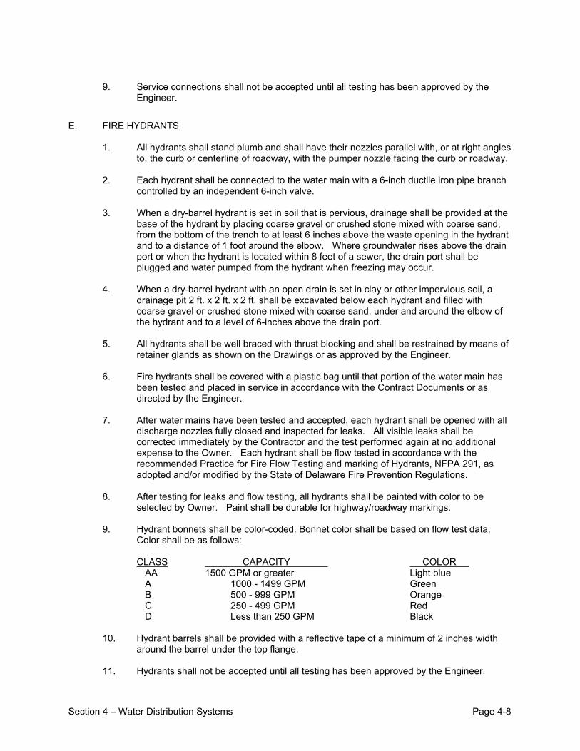
Section 4 – Water Distribution Systems Page 4-8
9. Service connections shall not be accepted until all testing has been approved by the Engineer.
E. FIRE HYDRANTS
1. All hydrants shall stand plumb and shall have their nozzles parallel with, or at right angles to, the curb or centerline of roadway, with the pumper nozzle facing the curb or roadway.
2. Each hydrant shall be connected to the water main with a 6-inch ductile iron pipe branch
controlled by an independent 6-inch valve. 3. When a dry-barrel hydrant is set in soil that is pervious, drainage shall be provided at the
base of the hydrant by placing coarse gravel or crushed stone mixed with coarse sand, from the bottom of the trench to at least 6 inches above the waste opening in the hydrant and to a distance of 1 foot around the elbow. Where groundwater rises above the drain port or when the hydrant is located within 8 feet of a sewer, the drain port shall be plugged and water pumped from the hydrant when freezing may occur.
4. When a dry-barrel hydrant with an open drain is set in clay or other impervious soil, a
drainage pit 2 ft. x 2 ft. x 2 ft. shall be excavated below each hydrant and filled with coarse gravel or crushed stone mixed with coarse sand, under and around the elbow of the hydrant and to a level of 6-inches above the drain port.
5. All hydrants shall be well braced with thrust blocking and shall be restrained by means of
retainer glands as shown on the Drawings or as approved by the Engineer. 6. Fire hydrants shall be covered with a plastic bag until that portion of the water main has
been tested and placed in service in accordance with the Contract Documents or as directed by the Engineer.
7. After water mains have been tested and accepted, each hydrant shall be opened with all
discharge nozzles fully closed and inspected for leaks. All visible leaks shall be corrected immediately by the Contractor and the test performed again at no additional expense to the Owner. Each hydrant shall be flow tested in accordance with the recommended Practice for Fire Flow Testing and marking of Hydrants, NFPA 291, as adopted and/or modified by the State of Delaware Fire Prevention Regulations.
8. After testing for leaks and flow testing, all hydrants shall be painted with color to be
selected by Owner. Paint shall be durable for highway/roadway markings. 9. Hydrant bonnets shall be color-coded. Bonnet color shall be based on flow test data.
Color shall be as follows: CLASS CAPACITY COLOR AA 1500 GPM or greater Light blue A 1000 - 1499 GPM Green B 500 - 999 GPM Orange C 250 - 499 GPM Red D Less than 250 GPM Black
10. Hydrant barrels shall be provided with a reflective tape of a minimum of 2 inches width around the barrel under the top flange.
11. Hydrants shall not be accepted until all testing has been approved by the Engineer.
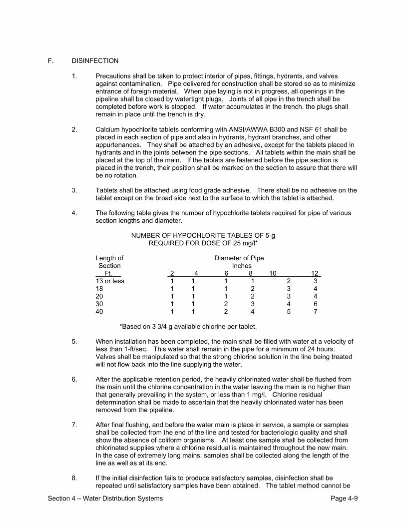
Section 4 – Water Distribution Systems Page 4-9
F. DISINFECTION
1. Precautions shall be taken to protect interior of pipes, fittings, hydrants, and valves against contamination. Pipe delivered for construction shall be stored so as to minimize entrance of foreign material. When pipe laying is not in progress, all openings in the pipeline shall be closed by watertight plugs. Joints of all pipe in the trench shall be completed before work is stopped. If water accumulates in the trench, the plugs shall remain in place until the trench is dry.
2. Calcium hypochlorite tablets conforming with ANSI/AWWA B300 and NSF 61 shall be
placed in each section of pipe and also in hydrants, hydrant branches, and other appurtenances. They shall be attached by an adhesive, except for the tablets placed in hydrants and in the joints between the pipe sections. All tablets within the main shall be placed at the top of the main. If the tablets are fastened before the pipe section is placed in the trench, their position shall be marked on the section to assure that there will be no rotation.
3. Tablets shall be attached using food grade adhesive. There shall be no adhesive on the tablet except on the broad side next to the surface to which the tablet is attached.
4. The following table gives the number of hypochlorite tablets required for pipe of various section lengths and diameter.
NUMBER OF HYPOCHLORITE TABLES OF 5-g REQUIRED FOR DOSE OF 25 mg/l*
Length of Diameter of Pipe Section Inches Ft. 2 4 6 8 10 12 13 or less 1 1 1 1 2 3 18 1 1 1 2 3 4 20 1 1 1 2 3 4 30 1 1 2 3 4 6 40 1 1 2 4 5 7
*Based on 3 3/4 g available chlorine per tablet.
5. When installation has been completed, the main shall be filled with water at a velocity of less than 1-ft/sec. This water shall remain in the pipe for a minimum of 24 hours. Valves shall be manipulated so that the strong chlorine solution in the line being treated will not flow back into the line supplying the water.
6. After the applicable retention period, the heavily chlorinated water shall be flushed from the main until the chlorine concentration in the water leaving the main is no higher than that generally prevailing in the system, or less than 1 mg/l. Chlorine residual determination shall be made to ascertain that the heavily chlorinated water has been removed from the pipeline.
7. After final flushing, and before the water main is place in service, a sample or samples shall be collected from the end of the line and tested for bacteriologic quality and shall show the absence of coliform organisms. At least one sample shall be collected from chlorinated supplies where a chlorine residual is maintained throughout the new main. In the case of extremely long mains, samples shall be collected along the length of the line as well as at its end.
8. If the initial disinfection fails to produce satisfactory samples, disinfection shall be repeated until satisfactory samples have been obtained. The tablet method cannot be
Section 4 – Water Distribution Systems Page 4-10
used in these subsequent disinfections. When the samples are satisfactory, the main may be placed in service.
9. The procedures outlined below apply primarily when mains are wholly or partially dewatered as a result of cutting into or repairing existing water mains. Leaks or breaks that are repaired with clamping devices while the mains remain full of water under pressure shall require no disinfection.
10. When existing water mains are excavated for repair work, the trench will likely be wet and badly contaminated from nearby sewers. Liberal quantities of hypochlorite applied to open trench areas will lessen the danger from such contamination. Tablets have the advantage in such a situation because they dissolve slowly and continue to release hypochlorite as water is pumped from the excavation.
11. The following procedure shall be considered as the minimum procedure used to disinfect water mains during repair work. The interior of all pipe and fittings used in making the repair, particularly couplings and tapping sleeves, shall be swabbed with a 1 percent hypochlorite solution before they are installed.
12. Thorough flushing shall be the means of removing contamination introduced during repairs. If valving and hydrant locations permit, flushing from both directions shall be provided. Flushing shall be started as soon as the repairs are completed and continued until discolored water is eliminated.
13. All disinfection procedures, requirements for bacteriologic tests, and determination of acceptability shall be subject to the requirements of the Delaware Health and Social Services, Division of Public Health.

Section 5 – Gravity Sewer Systems Page 5-1
SECTION 5 - GRAVITY SEWER SYSTEMS A. DESIGN CRITERIA
1. The Developer shall provide the Town with flow calculations supporting the gravity sewer system design. Average sewage flow shall be computed using 240 gallons per day per EDU. Peak flow for gravity sewer design shall be calculated as 4 times the average flow.
2. The minimum size of gravity sewer main shall be 8 inches inside diameter. Sewer laterals
shall have a minimum pipe size of 6 inches inside diameter.
3. The minimum depth of cover for sewer mains shall be 3 feet (36 inches) from finished grade to top of pipe.
4. Sewers shall be designed based on the Manning formula to provide a minimum flow
velocity of 2 feet per second (FPS) when flowing full. The Manning friction coefficient “n” used in velocity calculations shall be 0.011 for PVC pipe and 0.013 for ductile iron pipe. Where full flow conditions will not be reached, the pipe slope shall be increased to provide a 2 FPS minimum velocity at the design flow. Specifying oversized sewers for the purpose of using flatter slopes shall not be approved. Sewer slopes shall be greater than or equal to the following limits:
Pipe Size (inches)
PVC Min. Slope (Feet / 100 Feet)
Pipe Size (inches)
D.I. Min. Slope (Feet / 100 Feet)
8
0.30
8
0.40
10
0.22
10
0.28
12
0.17
12
0.22
15
0.12
14
0.17
18
0.10
16
0.12
21
0.08
18
0.14
24
0.06
20
0.12
27
0.05
24
0.05
30
0.06
36
0.05
5. Under no circumstances shall gravity sewers be designed to carry storm water flows.
6. Gravity sewer mains shall be located within street rights-of-way, under the center line of
the pavement to the extent possible. If it is not possible to locate a sewer main within a street right of way, the sewer main shall be located within a utility easement dedicated to The Town of Millsboro, obtained by the Developer.
7. Sewers shall be located at least 10 feet horizontally from any existing or proposed water
main. Sewers crossing water mains shall be located to provide a minimum vertical separation distance of 18 inches between the water main and the sewer. Crossings shall be arranged so that the joints in the sewer pipe will be as far as possible from water main
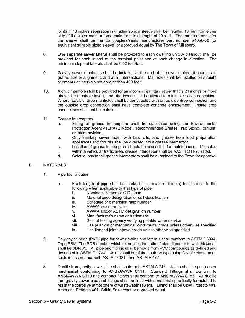
Section 5 – Gravity Sewer Systems Page 5-2
joints. If 18 inches separation is unattainable, a sleeve shall be installed 10 feet from either side of the water main or force main for a total length of 20 feet. The end treatments for the sleeve shall be Fernco couplers/seals manufacturer part number #1056-86 (or equivalent suitable sized sleeve) or approved equal by The Town of Millsboro.
8. One separate sewer lateral shall be provided to each dwelling unit. A cleanout shall be provided for each lateral at the terminal point and at each change in direction. The minimum slope of laterals shall be 0.02 feet/foot.
9. Gravity sewer manholes shall be installed at the end of all sewer mains, at changes in
grade, size or alignment, and at all intersections. Manholes shall be installed on straight segments at intervals not greater than 400 feet.
10. A drop manhole shall be provided for an incoming sanitary sewer that is 24 inches or more
above the manhole invert, and, the invert shall be filleted to minimize solids deposition. Where feasible, drop manholes shall be constructed with an outside drop connection and the outside drop connection shall have complete concrete encasement. Inside drop connections shall not be installed.
11. Grease Interceptors
a. Sizing of grease interceptors shall be calculated using the Environmental Protection Agency (EPA) 2 Model, “Recommended Grease Trap Sizing Formula” or latest revision.
b. Only sanitary sewer laden with fats, oils, and grease from food preparation appliances and fixtures shall be directed into a grease interceptor.
c. Location of grease interceptors should be accessible for maintenance. If located within a vehicular traffic area, grease interceptor shall be AASHTO H-20 rated.
d. Calculations for all grease interceptors shall be submitted to the Town for approval B. MATERIALS
1. Pipe Identification a. Each length of pipe shall be marked at intervals of five (5) feet to include the
following when applicable to that type of pipe: i. Nominal size and/or O.D. base ii. Material code designation or cell classification iii. Schedule or dimension ratio number iv. AWWA pressure class v. AWWA and/or ASTM designation number vi. Manufacturer's name or trademark vii. Seal of testing agency verifying potable water service viii. Use push-on or mechanical joints below grade unless otherwise specified ix. Use flanged joints above grade unless otherwise specified
2. Polyvinylchloride (PVC) pipe for sewer mains and laterals shall conform to ASTM D3034, Type PSM. The SDR number which expresses the ratio of pipe diameter to wall thickness shall be SDR 35. All pipe and fittings shall be made from PVC compounds as defined and described in ASTM D 1784. Joints shall be of the push-on type using flexible elastomeric seals in accordance with ASTM D 3212 and ASTM F 477.
3. Ductile Iron gravity sewer pipe shall conform to ASTM A 746. Joints shall be push-on or
mechanical conforming to ANSI/AWWA C111. Standard Fittings shall conform to ANSI/AWWA C110 and compact fittings shall conform to ANSI/AWWA C153. All ductile iron gravity sewer pipe and fittings shall be lined with a material specifically formulated to resist the corrosive atmosphere of wastewater sewers. Lining shall be Clow Protecto 401, American Protecto 401, Griffin Sewercoat or approved equal.
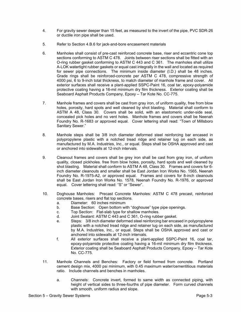
Section 5 – Gravity Sewer Systems Page 5-3
4. For gravity sewer deeper than 15 feet, as measured to the invert of the pipe, PVC SDR-26 or ductile iron pipe shall be used.
5. Refer to Section 4.B.6 for jack-and-bore encasement materials
6. Manholes shall consist of pre-cast reinforced concrete base, riser and eccentric cone top
sections conforming to ASTM C 478. Joints between riser sections shall be fitted with an O-ring rubber gasket conforming to ASTM C 443 and C 361. The manholes shall utilize A-LOK watertight rubber gaskets or equal cast integrally in the wall and located as required for sewer pipe connections. The minimum inside diameter (I.D.) shall be 48 inches. Grade rings shall be reinforced-concrete per ASTM C 478, compressive strength of 4000 psi, 6 to 9-inch total thickness, to match diameter of manhole frame and cover. All exterior surfaces shall receive a plant-applied SSPC-Paint 16, coal tar, epoxy-polyamide protective coating having a 16-mil minimum dry film thickness. Exterior coating shall be Seaboard Asphalt Products Company, Epoxy – Tar Kote No. CC-775.
7. Manhole frames and covers shall be cast from gray iron, of uniform quality, free from blow
holes, porosity, hard spots and well cleaned by shot blasting. Material shall conform to ASTM A 48, Class 30. Covers shall be solid, with an elastomeric under-side seal, concealed pick holes and no vent holes. Manhole frames and covers shall be Neenah Foundry No. R-1683 or approved equal. Cover lettering shall read: “Town of Millsboro Sanitary Sewer.”
8. Manhole steps shall be 3/8 inch diameter deformed steel reinforcing bar encased in
polypropylene plastic with a notched tread ridge and retainer lug on each side, as manufactured by M.A. Industries, Inc., or equal. Steps shall be OSHA approved and cast or anchored into sidewalls at 12-inch intervals.
9. Cleanout frames and covers shall be grey iron shall be cast from gray iron, of uniform
quality, closed pickholes. free from blow holes, porosity, hard spots and well cleaned by shot blasting. Material shall conform to ASTM A 48, Class 30. Frames and covers for 6-inch diameter cleanouts and smaller shall be East Jordan Iron Works No. 1565, Neenah Foundry No. R-1975-A2, or approved equal. Frames and covers for 8-inch cleanouts shall be East Jordan Iron Works No. 1578, Neenah Foundry No. R-1976, or approved equal. Cover lettering shall read: “S” or “Sewer”.
10. Doghouse Manholes: Precast Concrete Manholes: ASTM C 478 precast, reinforced concrete bases, risers and flat top sections. a. Diameter: 60 inches minimum b. Base Section: Open bottom with “doghouse” type pipe openings. c. Top Section: Flat-slab type for shallow manholes. d. Joint Sealant: ASTM C 443 and C 361, O-ring rubber gasket. e. Steps: 3/8 inch diameter deformed steel reinforcing bar encased in polypropylene
plastic with a notched tread ridge and retainer lug on each side, as manufactured by M.A. Industries, Inc., or equal. Steps shall be OSHA approved and cast or anchored into sidewalls at 12-inch intervals.
f. All exterior surfaces shall receive a plant-applied SSPC-Paint 16, coal tar, epoxy-polyamide protective coating having a 16-mil minimum dry film thickness. Exterior coating shall be Seaboard Asphalt Products Company, Epoxy – Tar Kote No. CC-775.
11. Manhole Channels and Benches: Factory or field formed from concrete. Portland cement design mix, 4000 psi minimum, with 0.45 maximum water/cementitious materials ratio. Include channels and benches in manholes. a. Channels: Concrete invert, formed to same width as connected piping, with
height of vertical sides to three-fourths of pipe diameter. Form curved channels with smooth, uniform radius and slope.
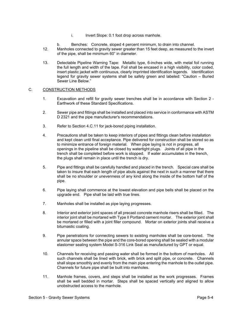
Section 5 - Gravity Sewer Systems Page 5-4
i. Invert Slope: 0.1 foot drop across manhole.
b. Benches: Concrete, sloped 4 percent minimum, to drain into channel.
12. Manholes connected to gravity sewer greater than 15 feet deep, as measured to the invert of the pipe, shall be minimum 60” in diameter.
13. Detectable Pipeline Warning Tape: Metallic type, 6-inches wide, with metal foil running
the full length and width of the tape. Foil shall be encased in a high visibility, color coded, insert plastic jacket with continuous, clearly imprinted identification legends. Identification legend for gravity sewer systems shall be safety green and labeled: “Caution – Buried Sewer Line Below.”
C. CONSTRUCTION METHODS
1. Excavation and refill for gravity sewer trenches shall be in accordance with Section 2 - Earthwork of these Standard Specifications.
2. Sewer pipe and fittings shall be installed and placed into service in conformance with ASTM
D 2321 and the pipe manufacturer's recommendations. 3. Refer to Section 4.C.11 for jack-bored piping installation.
4. Precautions shall be taken to keep interiors of pipes and fittings clean before installation
and kept clean until final acceptance. Pipe delivered for construction shall be stored so as to minimize entrance of foreign material. When pipe laying is not in progress, all openings in the pipeline shall be closed by watertight plugs. Joints of all pipe in the trench shall be completed before work is stopped. If water accumulates in the trench, the plugs shall remain in place until the trench is dry.
5. Pipe and fittings shall be carefully handled and placed in the trench. Special care shall be
taken to insure that each length of pipe abuts against the next in such a manner that there shall be no shoulder or unevenness of any kind along the inside of the bottom half of the pipe.
6. Pipe laying shall commence at the lowest elevation and pipe bells shall be placed on the
upgrade end. Pipe shall be laid with true lines.
7. Manholes shall be installed as pipe laying progresses.
8. Interior and exterior joint spaces of all precast concrete manhole risers shall be filled. The interior joint shall be mortared with Type II Portland cement mortar. The exterior joint shall be mortared or filled with a joint filler compound. Mortar on exterior joints shall receive a bitumastic coating.
9. Pipe penetrations for connecting sewers to existing manholes shall be core-bored. The
annular space between the pipe and the core-bored opening shall be sealed with a modular elastomer sealing system Model S-316 Link Seal as manufactured by GPT or equal.
10. Channels for receiving and passing water shall be formed in the bottom of manholes. All
such channels shall be lined with brick, with brick and split pipe, or concrete. Channels shall slope smoothly and evenly from the main pipe entering the manhole to the outlet pipe. Channels for future pipe shall be built into manholes.
11. Manhole frames, covers, and steps shall be installed as the work progresses. Frames
shall be well bedded in mortar. Steps shall be spaced vertically and aligned to allow unobstructed access to the manhole.
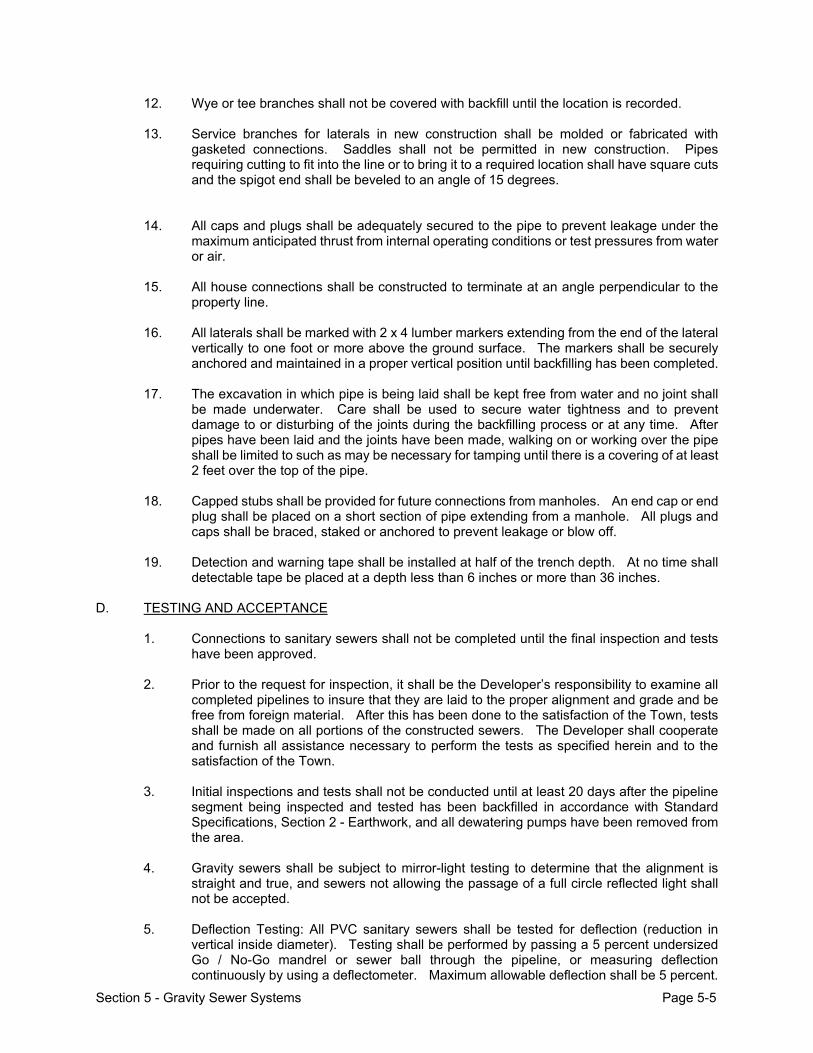
Section 5 - Gravity Sewer Systems Page 5-5
12. Wye or tee branches shall not be covered with backfill until the location is recorded.
13. Service branches for laterals in new construction shall be molded or fabricated with gasketed connections. Saddles shall not be permitted in new construction. Pipes requiring cutting to fit into the line or to bring it to a required location shall have square cuts and the spigot end shall be beveled to an angle of 15 degrees.
14. All caps and plugs shall be adequately secured to the pipe to prevent leakage under the maximum anticipated thrust from internal operating conditions or test pressures from water or air.
15. All house connections shall be constructed to terminate at an angle perpendicular to the
property line.
16. All laterals shall be marked with 2 x 4 lumber markers extending from the end of the lateral vertically to one foot or more above the ground surface. The markers shall be securely anchored and maintained in a proper vertical position until backfilling has been completed.
17. The excavation in which pipe is being laid shall be kept free from water and no joint shall
be made underwater. Care shall be used to secure water tightness and to prevent damage to or disturbing of the joints during the backfilling process or at any time. After pipes have been laid and the joints have been made, walking on or working over the pipe shall be limited to such as may be necessary for tamping until there is a covering of at least 2 feet over the top of the pipe.
18. Capped stubs shall be provided for future connections from manholes. An end cap or end
plug shall be placed on a short section of pipe extending from a manhole. All plugs and caps shall be braced, staked or anchored to prevent leakage or blow off.
19. Detection and warning tape shall be installed at half of the trench depth. At no time shall
detectable tape be placed at a depth less than 6 inches or more than 36 inches.
D. TESTING AND ACCEPTANCE 1. Connections to sanitary sewers shall not be completed until the final inspection and tests
have been approved.
2. Prior to the request for inspection, it shall be the Developer’s responsibility to examine all completed pipelines to insure that they are laid to the proper alignment and grade and be free from foreign material. After this has been done to the satisfaction of the Town, tests shall be made on all portions of the constructed sewers. The Developer shall cooperate and furnish all assistance necessary to perform the tests as specified herein and to the satisfaction of the Town.
3. Initial inspections and tests shall not be conducted until at least 20 days after the pipeline
segment being inspected and tested has been backfilled in accordance with Standard Specifications, Section 2 - Earthwork, and all dewatering pumps have been removed from the area.
4. Gravity sewers shall be subject to mirror-light testing to determine that the alignment is
straight and true, and sewers not allowing the passage of a full circle reflected light shall not be accepted.
5. Deflection Testing: All PVC sanitary sewers shall be tested for deflection (reduction in
vertical inside diameter). Testing shall be performed by passing a 5 percent undersized Go / No-Go mandrel or sewer ball through the pipeline, or measuring deflection continuously by using a deflectometer. Maximum allowable deflection shall be 5 percent.

Section 5 - Gravity Sewer Systems Page 5-6
6. Gravity sewers shall be subject to visual testing using closed circuit television (CCTV)
equipment suitably sized for the diameter of the sewer segments being tested. All obstructions and defects observed shall be corrected to the satisfaction of the Town.
7. Gravity sewers shall be subject to a low-pressure air test. Low-pressure air test shall be
completed in accordance with ASTM F1417: “Standard Test Method for Installation Acceptance of Plastic Gravity Sewer Lines Using Low-Pressure Air” and with UNI-B-6: “Recommended Practice for Low-Pressure Air Testing of Installed Sewer Pipe.” The Contractor shall furnish all equipment and personnel to conduct this test in accordance with the following procedure:
a. All branch fittings and ends of lateral stubs shall be securely plugged to withstand
the internal test pressures. The section of line being tested shall also be securely plugged at each manhole. All stoppers shall be adequately braced when required.
b. Air shall be slowly supplied to the plugged pipe line until the internal air pressure reaches 4.0 pounds per square inch greater than the average back pressure of any groundwater above the pipe, but not greater than 9.0 pounds per square inch. At least 2 minutes shall be allowed for temperature stabilization before proceeding further.
c. The rate of air loss shall then be determined by measuring the time interval required for the internal pressure to decrease from 3.5 to 2.5 psi above the average groundwater back pressure.
d. The line shall be considered acceptable if the time, T, in seconds required for the 1.0 psi pressure drop is not less than 0.0850 DK/Q Where: D = pipe diameter, inches L = length of line being tested, feet K = 0.000419DL, but not less than 1.0 Q = rate of loss of 0.0015 cu. ft./min./sq. ft. of internal surface
MINIMUM HOLDING TIME REQUIRED FOR A 1.0 PSIG PRESSURE DROP FOR SIZE AND LENGTH OF PIPE INDICATED FOR Q = 0.0015
Pipe Time for Minimum Length for Longer Specification Time for Length (L) Diameter Time Minimum Length Shown (min-sec) (Inches) min-sec) Time (ft.) (sec.) 100' 150' 200' 250' 300' 350' 400' 450' 4 3:46 597 .380 L 3:46 3:46 3:46 3:46 3:46 3:46 3:46 3:46 6 5:40 398 .854 L 5:40 5:40 5:40 5:40 5:40 5:42 5:42 6:24 8 7:34 298 1.520 L 7:34 7:34 7:34 7:34 7:36 8:52 10:08 11:24 10 9:26 239 2.374 L 9:26 9:26 9:26 9:53 11:52 13:51 15:49 17:48 12 11:20 199 3.418 L 11:20 11:20 11:24 14:15 17:05 19:56 22:47 25:38 15 14:10 159 5.342 L 14:10 14:10 17:48 22:15 26:42 31:09 35:36 40:04 18 17:00 133 7.692 L 17:00 19:13 25:38 32:03 38:27 44:52 51:16 57:41 24 22:48 099 1.368 L 22:48 34:11 45:35 57:00 68:23 79:47 91:10 102:34 27 28:57 088 1.731 L 28:51 43:16 57:42 72:07 86:33 100:58 115:24 129:49 30 35:37 080 2.137 L 35:37 53:25 71:14 89:02 106:51 124:34 142:28 160:16
8. If the measured leakage rate exceeds the allowable amount, additional tests shall be conducted on individual segments of the gravity sewer system as required to locate the leaks. Any observed leakages of the gravity sewers or manholes shall be repaired. Sanitary sewer showing signs of infiltration shall be tested for leakage infiltration in accordance with Paragraph 33.94, Water (Hydrostatic) Test of the “Recommended

Section 5 - Gravity Sewer Systems Page 5-7
Standards for Wastewater Facilities,” 2014 Edition. The maximum allowable amount of infiltration rate measured by the test shall be 25 gallons per inch of pipe diameter per mile per 24 hours. CCTV survey results shall be submitted to the Town for review and approval.
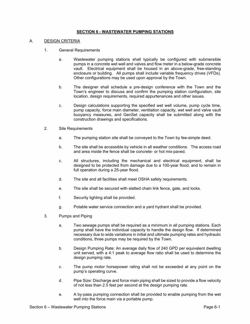
Section 6 – Wastewater Pumping Stations Page 6-1
SECTION 6 - WASTEWATER PUMPING STATIONS A. DESIGN CRITERIA
1. General Requirements
a. Wastewater pumping stations shall typically be configured with submersible pumps in a concrete wet well and valves and flow meter in a below-grade concrete vault. Electrical equipment shall be housed in an above-grade, free-standing enclosure or building. All pumps shall include variable frequency drives (VFDs). Other configurations may be used upon approval by the Town.
b. The designer shall schedule a pre-design conference with the Town and the
Town’s engineer to discuss and confirm the pumping station configuration, site location, design requirements, required appurtenances and other issues.
c. Design calculations supporting the specified wet well volume, pump cycle time,
pump capacity, force main diameter, ventilation capacity, wet well and valve vault buoyancy measures, and GenSet capacity shall be submitted along with the construction drawings and specifications.
2. Site Requirements
a. The pumping station site shall be conveyed to the Town by fee-simple deed.
b. The site shall be accessible by vehicle in all weather conditions. The access road
and area inside the fence shall be concrete- or hot mix-paved.
c. All structures, including the mechanical and electrical equipment, shall be designed to be protected from damage due to a 100-year flood, and to remain in full operation during a 25-year flood.
d. The site and all facilities shall meet OSHA safety requirements.
e. The site shall be secured with slatted chain link fence, gate, and locks.
f. Security lighting shall be provided.
g. Potable water service connection and a yard hydrant shall be provided.
3. Pumps and Piping
a. Two sewage pumps shall be required as a minimum in all pumping stations. Each
pump shall have the individual capacity to handle the design flow. If determined necessary due to wide variations in initial and ultimate pumping rates and hydraulic conditions, three pumps may be required by the Town.
b. Design Pumping Rate: An average daily flow of 240 GPD per equivalent dwelling
unit served, with a 4:1 peak to average flow ratio shall be used to determine the design pumping rate.
c. The pump motor horsepower rating shall not be exceeded at any point on the
pump’s operating curve.
d. Pipe Size: Discharge and force main piping shall be sized to provide a flow velocity of not less than 2.5 feet per second at the design pumping rate.
e. A by-pass pumping connection shall be provided to enable pumping from the wet
well into the force main via a portable pump.
Section 6 – Wastewater Pumping Stations Page 6-2
4. Wet Well
a. The minimum wet well operating volume for duplex, alternating pump systems shall be determined by the formula:
V = t Q / 4 where:
V= Minimum Operating Volume (Gallons) t = Minimum allowable time between starts of the same pump
based on motor manufacturer’s recommendations Q = Design pumping rate
b. Wet well floors shall be grouted to form a sump sloped at 1:1 toward the pump
inlets and in accordance with the pump manufacturer’s recommendations. A pump manufacturer’s preformed sump insert may also be specified.
c. Adequately sized access hatches shall be constructed for the installation and
removal of pumps and other equipment.
d. The wet well structure shall be designed to prevent positive buoyancy due to groundwater conditions. Buoyancy calculations shall be provided based on ground water elevation at the finished ground surface elevation.
5. Valves
a. Check valves and isolation valves shall be installed on all pump discharge lines.
The check valve shall be located between the pump and the isolation valve.
b. All valves regardless of type shall be located in a below-grade valve vault completely isolated from the wet well.
c. Valve vaults shall have adequately sized access hatches for entry by maintenance
personnel.
d. The valve vault structure shall be designed to prevent positive buoyancy due to groundwater conditions. Buoyancy calculations shall be provided based on ground water elevation at the finished ground surface elevation.
e. Refer to Section 7 of these Standard Specifications for air release and
combination air valves.
6. Ventilation
a. Adequate ventilation shall be provided for wet wells and valve vaults.
b. Pumping stations with a design flow of 200 gallons per minute or greater shall have a permanent mechanical ventilation in the wet well and valve vault. Wet well ventilation may be either continuous or intermittent.
c. Continuously operating ventilation equipment shall provide at least 12 complete air
changes per hour in the wet well, and 6 air changes per hour in the valve vault.
d. Intermittently operating ventilation shall provide at least 30 complete air changes per hour. Intermittent ventilation shall be controlled by programmable timer with manual override. Valve vaults shall be equipped with a position-type switch to run the ventilation system when the hatch cover is open.
Section 6 – Wastewater Pumping Stations Page 6-3
e. Mechanical ventilation shall force fresh air into below-grade structures.
7. Electric Service
a. Pumping stations shall have metered electrical service complying with all utility
company requirements, and an above-ground service entrance breaker switch.
b. Pumping stations shall be equipped with an emergency GenSet with the capacity to start and run the entire facility’s electrical load.
c. Voltage Requirements:
i. 240-volt AC, single-phase service shall be provided for pumping stations
with pumps rated 2HP or less. ii. 240-volt AC, three-phase service shall be provided for pumping stations
with pumps rated from 3HP to 40 HP. iii. 480-volt AC, three-phase service shall be provided for pumping stations
with pumps rated greater than 40HP.
8. Standby Genset
a. All pumping stations shall be equipped with a standby-rated diesel engine-generator set (Genset), an automatic transfer switch and all necessary controls and auxiliaries to start and run the entire facility’s electrical load during utility service outages.
b. The Genset shall have sufficient capacity to perform all pumping station electrical
functions, including starting the lag pump when all other electrical loads, including the lead pump, are connected.
c. The Genset shall be designed for unattended automatic operation and for manual
control. Instrumentation to provide adequate monitoring of performance under both conditions shall be provided.
9. Controls and Alarms
a. The pump control panel (PCP) shall monitor the water level in the wet well with a
continuous level transmitter and two (2) float switches. The transmitter level thresholds and level switch positions shall be set at heights in the wet well to serve the following functions: i. Level 6 - High High Level Alarm and Backup Pump Control (Float Switch) ii. Level 5 - High Level Alarm (Analog Transmitter Threshold) iii. Level 4 - Lag Pump On (Analog Transmitter Threshold) iv. Level 3 - Lead Pump On (Analog Transmitter Threshold) v. Level 2 - Pumps Off (Analog Transmitter Threshold) vi. Level 1 - Low Level Alarm and Backup Pump Control (Float Switch)
b. The PCP shall perform the following basic functions: i. Allow the operator to select any pump as a Lead pump. ii. Allow the operator to select automatic alternation of the Lead and Lag
Pumps on each successive start cycle. iii. On rise to Level 3 (Lead On), the Lead Pump shall start its associated
VFD and control its speed to maintain the Level 3 setpoint. The speed shall increase on rise in level to its full speed and decrease to its minimum speed on fall in level. The pump shall stop when level falls to Level 2.
iv. On rise to Level 4 (Lag On), the Lag Pump shall start and run until it stops at Level 2.
Section 6 – Wastewater Pumping Stations Page 6-4
v. On rise to Level 5 (High Level), energize an alarm circuit. vi. On rise to Level 6 (High-High Level), energize an alarm circuit and start
the lead pump. In the event that the lead pump does not start, the lag pump shall start after an adjustable start delay. Only one pump shall start on rise to Level 6.
vii. On fall to Level 2 (Pumps Off), stop all pumps. viii. On fall to Level 1 (Low Level), energize an alarm circuit and stop all
pumps. ix. In the event of a pump malfunction (overload trip, motor high
temperature, pump fail to run when called, pump fail while running), promote the next pump in line and run it in place of the failed pump (promote Lag to Lead).
x. If a pump has failed, the PCP should consider it unavailable and remove it from the alternation cycle. It shall remain unavailable until the alarm is reset at the PCP.
xi. Allow selection of “Maintain Level” or “Constant Speed” through the Human-Machine Interface (HMI).
xii. Allow manual adjustment of the pump speed through the HMI. xiii. The PCP shall monitor the status of the UPS for display on the OIT
Screen and initiating a UPS Failure alarm, which automatically switches to incoming power.
c. The PCP shall be equipped with the following devices: i. Intrinsically safe barriers for connection to instruments and switches
located in the wet well: level switches and submersible level transmitter. ii. A pump motor relay for overtemperature and seal leakage alarms for
each pump. iii. A Hand-Off-Auto selector switch for each pump. Switches shall be
heavy-duty, oil-tight and rated for the NEMA class of the enclosure (shall be provided in separate VFD enclosure)
iv. Alternation selector – selector switch(es) or other means of selecting pump alternation.
v. Controller and HMI with means of receiving and indicating the following conditions: - High Water Level (float switch to discrete input) - Low Water Level (float switch to discrete input) - Wet Well Level (4-20 mA transmitter to analog input) - Station Discharge Flow (4-20 mA transmitter to analog Input) - Power On - Pump A Run - Pump B Run - Pump A Seal Leak (dry contact from motor protective relay to
discrete input) - Pump B Seal Leak (dry contact from motor protective relay to
discrete input) - Pump A Motor Temperature High Alarm (dry contact from motor
protective relay to discrete input) - Pump B Motor Temperature High Alarm (dry contact from motor
protective relay to discrete input) - VFD-A Fault (for VFD) - VFD-B Fault (for VFD) - Alarm Output Contacts to the cellular pump monitoring and control
system
Section 6 – Wastewater Pumping Stations Page 6-5
d. A backup level control circuit, based on relays to start both pumps (with a time delay between each start) when the High Level switch is activated and stop both pumps when the Low Level switch is activated.
e. Field terminals
f. Graphic Screens - graphics screens shall include, but not limited to the following: i. Animate these screens to dynamically represent level in a graphic format. Provide numerical displays of all current analog inputs scaled to the appropriate engineering units with dynamic links to detail screens showing trends. ii. Wet Well level in feet from bottom of wet well. iii. Animate graphic device symbols for pumps to reflect current status of the
device (Green = running, Red = alarm, Flash Yellow = failure alarm) B. MATERIALS AND PRODUCTS
1. Wet Well and Valve Vault
a. Wet wells shall be constructed of precast reinforced concrete base and riser sections, in conformance with ASTM C 478. All joints shall be gasketed in conformance with ASTM C 443. Openings for pipe connections shall be fitted with cast in place resilient A-Lok or Z-Lok seals, or mechanical link-seals.
b. Valve vaults shall be precast concrete reinforced for H-20 bridge loading provided
in two (2) sections for exterior heights up to 8'-0" and in three (3) sections for additional heights. Joints of sections shall be gasketed and sealed watertight when installed.
c. Top slabs shall be cast-in-place reinforced concrete.
2. Access Hatch Frames and Covers
a. Access hatch frames shall be 6063-T6 aluminum extrusion with a continuous
anchor feature incorporated. Frames shall be designed to direct rain water via the channel frame to a drain connection. Covers shall be 1/4" aluminum 6061-T6 alloy diamond pattern plate.
b. Covers in non-traffic areas shall be reinforced to withstand a live load of 300 pounds
per square foot. Covers subject to off-street vehicular traffic loads shall be reinforced for an AASHTO H-20 rating.
c. Covers shall be equipped with a minimum of two heavy duty hinges with stainless
steel pins, an automatic hold-open arm and an enclosed stainless steel spring assist. A recessed lock box shall be provided. All hardware shall be stainless steel.
d. All material shall have a standard mill finish. The embedded portion of the frame
shall receive a heavy shop coat of bituminous paint where in contact with concrete.
e. Hatch frames and covers shall be Series W1S or W2S as manufactured by Halliday Products, Inc., Type J-AL or JD-AL as manufactured by The Bilco Company, or approved equal.
3. Pipe, Fittings and Valves
a. All pumping station piping shall be ductile iron pipe, conforming to AWWA C 151,
cement-lined and bituminous-coated inside and out in accordance with AWWA C 104.
Section 6 – Wastewater Pumping Stations Page 6-6
b. Joints for buried ductile iron pipe shall be mechanical or push-on in accordance with AWWA C 110 and C 111. Flanged joints in accordance with AWWA C 110 shall be provided on exposed ductile iron pipe.
c. Fittings for ductile iron pipe shall conform to AWWA C 110, Class 250 gray cast iron
or Class 350 ductile iron conforming to ASTM A 536, minimum grade 70-50-05. Nominal thickness of fittings shall be equal to, or exceed, Class 53 ductile iron pipe thickness. Fittings shall be cement lined in accordance with AWWA C 104.
d. Horizontal swing check valves shall be flanged, iron body, bronze mounted, swing
gate, with outside lever and adjustable weight type, rated for the same pressure as the pipe in which installed. Bonnet shall be sufficiently large to permit cleaning and maintenance of the inner works without removing the valve body from the line. Valves shall be Figure 106LW as manufactured by Kennedy Valve, or equal.
e. Ball check valves shall be flanged, cast iron body. The ball shall be hollow steel
with an exterior of nitrile rubber, resistant to sewage, grease petroleum products, tearing and abrasion. Valves shall be HDL Type 2016 as manufactured by ITT Flygt Corporation, or approved equal.Isolation valves shall be resilient wedge gate valves conforming to AWWA C515. Valve wedge shall be constructed of ductile iron, encapsulated in resilient rubber. Wedge rubber shall be molded in place and bonded to the ductile iron wedge, not mechanically attached with screws or rivets. Waterway shall be smooth and shall have no depressions or cavities in the seat area. Valve body and bonnet shall be epoxy coated, inside and out with fusion bonded epoxy conforming to AWWA C550. Buried valves shall be fitted with 2 inch square operating nuts. Valves located above ground or in vaults shall be equipped with handwheel, chainwheel or lever operators. Valves shall as manufactured by Clow, American Flow Control, or equal.
f. Valve boxes shall be 3-piece adjustable screw type, 5 1/4 inch shaft diameter with
"SEWER" cast in the cover. Valve boxes shall be as manufactured by Tyler, Mueller, Clow, Kennedy, M&H, or equal.
g. Yard hydrants shall be non-freeze type with galvanized steel pipe casing, cast iron
head and lift handle with locking capability. All operating parts shall be bronze. Valve housing shall be equipped with a drain port. Furnish hydrant with a 3/4-inch male hose connection and vacuum breaker. Zurn, Z1396, or equal.
h. Backflow preventers, where required by the Town, shall utilize the reduced
pressure principle and shall consist primarily of a pressure differential relief valve located in a zone between 2 positive seating check valves. The relief valve shall contain a separate means whereby free air will enter the zone, and contained water will be discharged to atmosphere when the valve is fully open. The assembly shall include two tightly closing shut-off valves, one before and one after the device, and test cocks. The device shall meet all requirements of ASSE standard 1013 and AWWA C506, latest revision. Backflow preventers shall be Watts series 909 HW, Conbraco, Series 40-200 or equal.
i. A magnetic flow meter sensor shall be installed on the discharge piping in the valve
vault. The magnetic flow meter shall consist of a primary sensor rated for submersible duty IP-68 protection rating and a remotely mounted transmitter. Both the meter and transmitter shall be the product of a single manufacturer. The flow meter shall be factory calibrated. The flow meter sensor shall be model MAG 5100W by Siemens. The transmitter shall be model MAG 5000 by Siemens.
4. Submersible, Solids-Handling Sewage Pumps
a. Submersible, solids-handling sewage pumps shall be Type NP or Type CP as
Section 6 – Wastewater Pumping Stations Page 6-7
manufactured by ITT Flygt Corporation, unless otherwise approved by the Town.
b. A Pump Monitor Relay (PMR) shall be provided with the pumps to provide Motor Over Temperature and Seal Leakage alarms. The PMR will be furnished by the pump vendor for installation in the Pump Control Panel (PCP) and wired to the pump controls for shutdown and alarming. The PMR shall be flush mounted in the door of the PCP. The Seal Leakage alarm shall disable the respective pump and initiate an alarm on the OIT alarm screen and maintain until the alarm is reset. The Over Temperature shall disable the pump until the motor housing cools off. The Over Temperature condition shall initiate an alarm on the OIT alarm screen.
c. Each pump shall be equipped with a lifting system with a rated capacity at least 50
percent greater than the weight of the pump. A portable davit crane in flush mount base shall be provided and have 360 degree pivoting 316 stainless steel boom and 316 stainless steel wire rope. Davit crane shall be stainless steel, Ensign Series by Thern with type M3 stainless steel spur gear hand winch with brake. For applications that exceed the rated lifting capacity of the Thern Ensign Series, or equal. An adhesive vinyl decal with the weight capacity rating shall be applied to the crane mast.
5. Submersible Grinder Pumps
a. Submersible sewage grinder pumps shall be Type MP as manufactured by ITT
Flygt Corporation, unless otherwise approved by the Town.
b. Pump monitor relay and lifting system shall be provided for submersible grinder pumps; refer to Part B.4 above.
6. Variable Frequency Drives
a. AC Drive shall be Altivar 660 Drive System by Schneider Electric. AC Drive shall
include line reactors. No substitutions allowed.
b. Alternate control techniques, other than pulse width modulated (PWM) control, are not acceptable.
c. Adequate reserve space shall be provided around the AC Drive, either inside the electrical equipment enclosure or on the wall of the control building, for future replacement of the AC Drive.
7. Level Controllers
a. Level transducers shall be a KPSI model 720T with the following options:
i. Titanium construction
ii. Sealed gage
iii. 4-20 mA output
iv. Open face nose cap
v. Lifetime lightining/surge protection
vi. Stainless Steel cable hanging kit and anchor kit
vii. Series 815 Aneroid Bellows
b. Float Switches shall be EZconnex Narrow-Angled Floats in the cable weight mounting configuration. Floats shall be supplied with a 3-port manifold, a sealing plug, and 6 hook bracket.
8. Odor Control Systems
Section 6 – Wastewater Pumping Stations Page 6-8
a. A passive vent scrubber shall be provided on wet well exhaust vent(s). Passive
vent scrubber shall be model PV40 by Purafil Filtration Group. b. For proposed pumping stations located near residential or business
establishments and at the discretion of the Town, a powered odor control system shall be provided in lieu of a passive vent scrubber. The powered odor control system shall include stainless steel adsorber canister(s) with manufacturer’s odor adsorbing media, centrifugal blower, weather resistant acoustical enclosure, process stream piping, and packaged remote mount controller/control panel with variable frequency drive. All equipment and material shall be furnished and coordinated by a single manufacturer. Odor control system shall be model Skid Mounted Stainless Steel Series (SMSS) manufactured by EZ Vent LLC.
9. Electrical Equipment Enclosure
a. Electrical equipment enclosures shall be aluminum NEMA 3R rating adequately sized to house all electrical and control panels. The enclosure shall be furnished with an interior panel mounted on channels welded horizontally to interior body sides at top, bottom and center. Doors shall have oil resistant gaskets with steel retaining strips, grounding stud, print pocket and screws and clamps on three sides. Drip proof lips shall be provided over all louvers and doors.
b. Enclosure accessories and modifications shall include:
i. A thermostatically controlled cooling fan package consisting of a fan, air
filter, air plenum and finger guard and stainless steel grille. ii. Stainless steel louver plates with air filters on intake and exhaust
openings, Hoffman A-VK series or equal. iii. Thermostatically-controlled electric heater(s), Hoffman D-AH series, or
equal. iv. Enclosure lighting consisting of fluorescent strip fixture(s) with manual
switch and cold weather ballast, Hoffman A-LF series, or equal.
10. Circuit Breaker Panel
a. Busbars and all current carrying parts of circuit breaker panels shall be copper sized in accordance with the requirements of the Underwriters Laboratories, Inc. Branch circuits shall be comprised of the required number of interchangeable screw-down type magnetic circuit breakers. Plug-in breakers are acceptable in single-phase panels only. Tandem breakers shall not be acceptable.
b. Panel enclosures shall be NEMA type 3R steel with baked-on enamel finish. Trim
shall include fully hinged door, locking handle, and card holder. All enclosures shall be for surface mounting.
c. Circuit breakers shall have quick-make and quick-break toggle mechanisms, non-
fusible contact with inverse-time, interrupting characteristics. Breaker shall trip free on overload. They shall indicate clearly whether they are in the open or closed position. Multi-polar units shall have a single handle. Circuit breakers shall be bolted or plug-in as appropriate for the panel, readily removable from front of panelboard without disturbing adjacent units. All circuit breakers shall have interrupting ratings as follows:
i. 480 or 277 volt service 14,000 amps minimum ii. 240 or 120 volt service 10,000 amps minimum
d. Ground fault interrupting breakers shall be provided on all circuits supplying
receptacles and as otherwise required by the latest revision of the National Electrical Code.
Section 6 – Wastewater Pumping Stations Page 6-9
e. All electrical components shall be manufactured by Square D. No substitutions
shall be allowed.
11. Pump Control Panel
a. Enclosures shall be NEMA type 3R aluminum with baked-on enamel finish and an interior hinged deadfront panel.
b. The control system shall operate on 120 volt AC, single phase power supply unless
otherwise approved by the Town.
c. All equipment and materials shall be suitable for operation at rated capability without degradation and without exceeding rated operating temperatures under ambient temperatures from -100 to 1100F and up to 100 percent ambient relative humidity.
d. Panels shall be UL-508 certified.
e. Controllers/PLCs:
i. Programmable logic controller (PLC) with operator interface terminal (OIT) shall be provided instead of the use of relays, switches and indicator lights. ii. Programming Language: Relay Ladder Logic. iii. Software: Licensed copies of PLC & OIT programming software shall be
provided. iv. Manufacturer & Model: Schneider Electric SCADAPack for PLC and
Schneider Electric, Square D HMIGTO5310 for OIT. No substitutions will be accepted.
12. Cellular Pump Monitoring and Control System
a. Remote pump monitoring and control system shall be microprocessor based
monitor and backup controller on a cellular platform, model Crystal Ball by OmniSite in a NEMA 4X enclosure with remote mount high gain antenna and associated cables. Contractor shall furnish, install and test, complete and in place, the cellular remote alarm monitoring system including antenna and cables.. No substitutions shall be accepted.
b. The monitoring and control system shall have the following inputs:
i. Wet Well Water Level
ii. Discharge Flow
iii. Pump A Running
iv. Pump B Running
v. Pump A Failure (includes VFD failure)
vi. Pump B Failure (includes VFD Failure)
vii. Genset Run (direct from Genset)
viii. Wet Well Analog Low Level
ix. Wet Well Analog High Level
x. Genset Low Fuel (direct from Genset)
xi. Backup Level Control Active (from Backup Level Control circuit)
Section 6 – Wastewater Pumping Stations Page 6-10
xii. AC Power Failure (direct from ATS)
xiii. PLC Failure
c. Other monitoring and control functions consist of the following:
i. Maintain elapsed running time record of the two (2) pumps through elapsed time counters or Programmable Logic Controller (PLC)/Operator Interface Terminal (OIT).
ii. Maintain flow record of effluent discharge via flow transmitter.
13. Conduit and Wiring
a. Conduits shall be IMC or hot dipped galvanized rigid steel. All metal conduit fittings shall be of a type which will maintain the grounding conductivity of the conduit system.
b. Liquid tight flexible conduits shall be constructed of spirally wound and interlocked
galvanized steel strip covered with an extruded polyvinyl chloride jacket. A continuous copper ground conductor shall be built into the core for permanent circuit and ground protection in conformance with provisions of Article 351 of the National Electric Code.
c. Junction and device boxes installed outside and in below-grade structures shall be
gasketed watertight types and shall have watertight threaded conduit hubs. Junction, pull and device boxes installed inside buildings shall be NEMA-1 or non-gasketed galvanized pressed steel.
d. All wire shall be single conductor copper, 600 volt type THHN/THWN or XHHW.
Minimum size shall be No. 12, except for control wires which may be No. 14. No. 8 and larger wire shall be stranded copper. All wire shall be clearly labeled with type, size, and voltage rating and color code shall conform to NEC.
e. Connections for No. 10 wire and smaller shall be made with approved type
pressure connectors and insulating caps (wire nuts). Splices and connections in No. 8 wire and larger shall be made with approved type sleeve connectors and insulated to the same thickness as the adjoining wire insulation.
14. In-Line Centrifugal Fans
a. Wet well and valve vault in-line centrifugal fans shall be FR Series by Fantech, or
equal.
b. Blower ducts shall be Schedule 80 PVC or Schedule 20 Galvanized Steel
15. Standby Generator Set (Genset)
a. A standby generator set (Genset) shall be provided for backup power in the event of a power failure. The Genset and all major auxiliary equipment shall be manufactured by Cummins Power Generation. No substitutions shall be accepted.
b. The Genset shall withstand the following environmental conditions without mechanical or electrical damage or degradation of performance capability:
i. Altitude: Sea level to 500 feet ii. Ambient temperatures: Min.-10oF (-230C), Max. 104oF (400C) iii. Relative humidity: 0 to 95 percent iv. Salt atmosphere during storm conditions v. Dust laden air

Section 6 – Wastewater Pumping Stations Page 6-11
vi. Insects/rodents vii. Fungus growth
c. The Genset unit shall be capable of carrying the full rated load without reduction in performance requirements throughout the period of any and all interruptions to the normal power supply. Temperature rise shall be within NEMA MG 1-22.40 definition.
d. The Genset shall produce the following voltage and frequency regulation under the
conditions stated:
i. Under steady state, i.e. slowly changing, conditions, the terminal voltage and frequency shall remain constant within plus or minus one half percent of rated or set value.
ii. Frequency regulations shall not exceed 5 percent and voltage regulation shall not exceed 2 percent of rated or set value under any loading sequence from no-load to full load.
iii. Instantaneous voltage dip shall not exceed 20 percent of rated or set value and frequency shall not fall below 5 percent of rated value when full load at rated power factor is applied to the alternator. Recovery to stable condition at rated voltage and frequency shall occur within 2 seconds.
e. A rheostat control shall provide a minimum of plus or minus 5 percent voltage
adjustment from rated value.
f. With the Genset unit carrying the full connected load, less the largest single motor load, the start-up of the largest single motor load shall not cause the voltage, frequency, and recovery time to fall outside the limits specified herein.
g. Neither rejection of the full rated load nor rejection of the largest single motor load
when the unit is carrying full rated load shall cause a speed rise in excess of the lower of the following:
i. 15 percent of rated speed. ii. 75 percent of the difference between the overspeed trip set point and rated
speed.
h. Engine shall be 4-cycle, diesel-fueled and equipped with the following:
i. Fuel system including pumps, piping and fuel handling apparatus as required to supply diesel fuel to the engine.
ii. Combustion air system including air cleaner. iii. Lubrication system supplied by a positive displacement oil pump. iv. Cooling system with thermostatically controlled water jacket heater. v. DC electrical system including but not limited to starting motor with positive
drive pinion engaging device and heavy-duty lead acid type batteries mounted on the engine skid.
vi. Exhaust system including but not limited to critical-type muffler to provide at least 30 decibel noise attenuation at 1,000 Hz., exhaust piping, and flexible exhaust connections.
i. Alternator shall conform to the following:
i. The alternator shall be synchronous, revolving field, brushless type, open
drip-proof design meeting in all respects provisions of NEMA MG-1 (ANSI C50.1) and the following: • Stator shall be solidly mounted to the engine flywheel housing.

Section 6 – Wastewater Pumping Stations Page 6-12
Windings and leads shall be designed and adequately secured to withstand maximum short circuit current, normal operating forces and vibration without distortion and movement.
• Rotor shall be mounted in durable sealed, prelubricated bearings and driven through a coupling so designed as to assure continuous and permanent rotor alignment.
• Grounded terminal with non-ferrous contact surfaces. ii. Class H materials shall be used for insulation of the rotor and stator in
conformance with NEMA MG-1. The rotor shall be impregnated with 100 percent solid epoxy resin and stator and other insulation shall be twice sprayed with varnish conforming to MIL-1-24092, Type M, Class 155, or equal method to maximize resistance to environmental factors, fungus, and other damage.
iii. Output connections shall provide for solidly grounded neutral. iv. Excitation shall be provided by a brushless rotating rectifier exciter system.
The exciter shall be controlled by a temperature compensated solid state automatic voltage regulator with quick-response characteristics. The voltage regulator shall be powered by a separate permanent magnet generator (PMG) located on the end of the main Genset shaft.
v. Voltage wave form shall meet the requirements of NEMA MG-1 with total harmonic content less than 6 percent. Telephone influence factor shall meet NEMA MG-1.
j. Control System
i. The control, surveillance and protection system shall provide for complete
startup, run, and shutdown of the Genset, in both automatic and manual modes with load or no-load selection feature and selector switch. The system shall include engine start/stop controls wired for manual switch control at the engine and from a remote circuit fully coordinated with the start/stop sensing device.
ii. Engine controls and indicating devices shall include: • RUN - STOP - REMOTE switch • Remote start/stop terminals • Oil pressure gauge • Coolant temperature gauge • DC volt meter • Contacts to provide positive shutdown for low oil pressure, high
coolant temperature, overcranking or overspeed conditions. • A common alarm contact and alarm annunciator to provide
mechanical indication of the alarm source.
• An extra set of dry contacts for connection to the monitoring and control system to indicate that the Genset has failed to operate.
iii. Genset controls and indicating devices shall include: • AC Voltage adjusting rheostat (+/- 5 percent) • Running time meter • AC Voltmeter connected line to line • AC Ammeter to measure current in each ungrounded line • Frequency meter • Voltmeter and ammeter phase selection switches. • Exciter circuit breaker with manual reset and alarm indication
wired to annunciator. iv. A main-line circuit breaker shall be provided as an integral part of the
Genset package. The breaker shall be equipped for manual operation as well as automatically controlled for overload and fault conditions. Rating
Section 6 – Wastewater Pumping Stations Page 6-13
shall be as determined by manufacturer but in no case less than the continuous standby current rating of the unit and conforming to NEMA MG-1 and NEC requirements for breaker ratings.
v. Fault current sensing together with alarm indication to annunciator shall indicate Genset breaker opening in the event of phase or ground fault. The type of fault, i.e., phase or ground shall be displayed and maintained on Genset panel until manually reset. Loss of voltage shall not inhibit the display.
k. Accessories shall include the following:
i. A welded and bolted reinforced heavy gauge steel, weatherproof
enclosure bolted to the Genset base. The enclosure shall have lockable inspection doors located for easy access to control equipment and maintenance points. Expanded metal louvers shall be provided for air intake and radiator discharge. Exhaust piping and silencer mounting shall be sealed or flanged to ensure a weatherproof installation. Mounting of components shall be accomplished in such a way that vibration effect is not an inherent problem.
ii. Vibration isolators mounted between the Genset and the sub-base fuel tank.
l. Spare parts shall be furnished with each Genset as follows:
i. 1 spare air filter element ii. 1 spare of each oil filter iii. 1 spare of each fuel filter
16. Automatic Transfer Switch
a. Automatic transfer switches shall be Transfer Switch-Onan Power Command 225A
or higher, as manufactured by Cummins Power Generation. No substitutions shall be accepted. The transfer switch shall be rated for continuous duty and sized to handle the full-load amperage of the pumping station main entrance breaker or the emergency Genset whichever is higher. The equipment shall be UL-1008 listed and shall conform to appropriate Standard ICS 2-447.
b. The automatic transfer switch control system shall designed for utility-to-Genset
application. When the utility power fails or is unsatisfactory, the switch shall start the Genset and transfer the load to the Genset. It shall return the load to the utility source upon its return to service.
c. The transfer switch shall be mechanically interlocked to positively ensure only one
source being connected to the load both during and after transfer operations. The switch shall be electrically operated by a single-solenoid mechanism energized from the source to which the load is connected. A manual operator shall also be provided.
d. The enclosure shall be Type 3R for outdoor use. The indicator panel shall include:
i. Source Available/Connected LED indicators ii. Test/Exercise/Bypass buttons
e. The control module functions shall include, but not be limited to the following items:
i. Monitor the normal incoming phases with voltage sensing devices to drop
out in an adjustable range of approximately 70 to 90 percent of nominal voltage, and to pick up in an adjustable range of approximately 80 to 98
Section 6 – Wastewater Pumping Stations Page 6-14
percent of nominal voltage. The settings shall determine initiations of "transfer to emergency" signal and initiation of "return to normal" signal respectively.
ii. Time delay and appropriate contacts to override momentary outages or fluctuations.
iii. Time delay on transfer to and from emergency source. iv. Time delay and appropriate contacts to re-transfer to normal source. v. Time delay and appropriate contacts to permit Genset cool down after
switching of load to normal source. vi. Programmed transition feature that provides an adjustable open period
during transfer and retransfer. vii. Override of "return to normal" delay and appropriate contacts to effect
immediate return to normal service in the event of standby service failure after normal service has returned.
viii. Transfer of load to standby source shall be inhibited unless standby source voltage is at least 90 percent of nominal and frequency is at least 95 of nominal. Standby sensing may be single phase monitored.
ix. Test switch to simulate normal service failure with option to test under load or no load.
x. Programmable Genset exerciser for automatic test operation. The timer period shall be adjustable to permit runs adjustable in 15 minute increments at least once per week.
xi. Date/time-stamped event recording
f. 250 VAC, 10 amp, Form "C" auxiliary dry contacts (one normally open, one normally closed) shall be provided for normal and emergency source positions.
g. A 10 amp, solid state automatic battery charger, capable of charging the engine
starting batteries from a discharged condition full float voltage condition in a period of not more than eight hours, shall be mounted inside the transfer switch cabinet.
17. Chain-Link Fencing
a. Fencing shall be manufactured by Seagull Fence and Concrete LLC, or equal
b. Fence fabric shall be 2-inch mesh, knuckle x twist chain link, extruded and bonded
vinyl coating on 9-gauge, 0.148 inch O.D. zinc coated steel. Minimum height shall be 6 feet. Fabric shall meet the requirements of ASTM F-668 and the Chain Link Fence Manufacturers Institute Product Manual.
c. The PVC coatings shall be continuously bonded, not sprayed or dipped, by
extrusion bonding under pressure of 5,000 psi. Color shall be selected by the Town from manufacturer’s full range of available color options.
d. Top locking, double-walled, vinyl privacy slats shall be installed in the fence fabric. Privacy slats shall be manufactured by Slat Source .
e. All posts shall be Type I, hot-dipped galvanized steel in accordance with ASTM F-
1083 for standard-weight SP40 (Schedule 40) vinyl coated pipe. Posts and rails shall be polymer coated in accordance with ASTM F-934. Line and terminal posts shall be 1-5/8 inches O.D., and gate posts 4 inches O.D, 6.55 lbs. per foot. Concrete footing, 12 inch diameter, 42” depth. Top and bottom rails shall be 1-5/8 inches O.D.
f. Bracing shall be terminal posts braces and trussed to the nearest line post and vinyl
coated 3/8 inch truss rod and vinyl coated truss road tightener.
g. The wire shall be 8-1/4 inches vinyl coated 9-guage. Tie wire spaced 15 inches on center for line posts and 24 inches on center for rails.
Section 6 – Wastewater Pumping Stations Page 6-15
h. Swing gates shall conform to ASTM F-900 and shall include gate stops, pad locks and keys.
18. Paint
a. Products: Products that may be incorporated into the Work include, but are not limited to, products as follows: i. Tnemec Company (Referenced for the purpose of establishing standards
of acceptability) ii. All paint materials selected for coating systems for each type of surface
shall be the product of a single manufacturer. b. Colors: As selected from manufacturer’s full color range. c. The type of material to be used and the number of coats to be applied are listed in
the “Painting Schedule” in this section. d. The following items shall be painted:
STRUCTURE LOCATION SURFACES TO BE PAINTED
Cast-in-Place Concrete Structures
Interior Ferrous Metals, Concrete
Precast Concrete Structures Interior, Exterior Ferrous Metals, Concrete
e. Painting Schedule Mil DFT
Below Grade Exterior Concrete 1. First: Tnemec Series 46H-413 8.0-10.0 2. Finish: Tnemec Series 46H-413 8.0-10.0
Corrosive/H2S Immersion Concrete Lining (wet well) 1. Resurfacer: Tnemec Series 218 Mortar Clad 1/16” 2. Body Coat: Tnemec Series 434 PermaShield 125 3. Glaze Coat: Tnemec Series 435 PermaGlaze 15-20
Non-Corrosive/ Benign Concrete 1. Filler: Tnemec Series 130 Envirofill as needed 60-80 SF / Gal 2. Intermediate: Tnemec Series V69 Hi-Build Epoxoline II 4.0-6.0 3. Finish: Tnemec Series V69 Hi-Build Epoxoline II 4.0-6.0
Interior CMU 1. Filler: Tnemec Series 130 Envirofill 60-80 SF / Gal 2. Intermediate: Tnemec Series 113 Tneme-Tufcoat 4.0-6.0 3. Finish: Tnemec Series 113 Tneme-Tufcoat 4.0-6.0
Exterior Masonry/CMU 1. Filler: Tnemec Series 130 Envirofill 60-80 SF / Gal 2. Prime: Tnemec Series 156 EnviroCrete 6.0-8.0 3. Finish Coat: Tnemec Series 156 EnviroCrete 6.0-8.0
H2S Exposure Ductile Iron Pipe 1. Prime: Tnemec Series 394 PerimePrime 2.5-3.5 2. Intermediate: Tnemec Series V69 Hi-Build Epoxoline II 4.0-6.0 3. Stripe Coat: Tnemec Series V69 Hi-Build Epoxoline II 3.0-5.0 4. Finish Coat: Tnemec Series 435 PermaGlaze 15.0-20.0
Non Corrosive Exposure Ductile Iron Pipe 1. Prime: Tnemec Series V69 Hi-Build Epoxoline II 4.0-6.0 2. Finish: Tnemec Series V69 Hi-Build Epoxoline II 4.0-6.0
Section 6 – Wastewater Pumping Stations Page 6-16
D. CONSTRUCTION METHODS
1. Excavation and refill for pipe trenches and structures shall conform to Section 2 - Earthwork of these Standard Specifications.
2. Cast-in-place concrete shall conform to Section 3 - Concrete of these Standard
Specifications.
3. Wet well level control devices shall be located free from any effects of turbulence of flows or suction.
4. Pumps
a. Each submersible pump shall be automatically and firmly connected to its discharge
connection, guided by two Schedule 40, 304 stainless steel guide rails extending from the access hatch to the discharge pipe connection. Sealing of the pumping unit to the discharge connection shall be accomplished by a machined metal to metal watertight contact. No portion of the pump shall bear directly on the sump floor.
b. All power, control and signal conductors shall be continuous from the device to the
control panel. There shall be no junction boxes or splices of any kind in these conductors.
5. Electrical Installation
a. All equipment furnished and electrical installations shall conform to all applicable
requirements and recommendations of national, state, and local codes and regulations. These codes and regulations shall include but are not limited to: ANSI, IEEE, ICEA, NEC, NEMA, OSHA, UL, and Conectiv.
b. Contractor shall give to the proper authorities all required notices, file all necessary
drawings and documents, obtain all required permits, licenses, and inspections, and pay all fees for the same. Upon completion of the work a certificate of inspection for work under this contract shall be obtained from an authorized Delaware inspection agency by the Contractor and submitted to the Engineer.
c. All damage resulting from drilling, cutting, and other electrical construction work
shall be repaired or patched in a neat and permanent manner by competent tradesmen at the expense of the Contractor. Cutting or drilling of building construction or supporting materials shall not create any structural weakness. All cutting and repairs shall meet the approval of the Engineer.
d. Electrical equipment such as panel boards, switches, controls, junction and pull
boxes, and such other apparatus as may require maintenance or operation shall be located to provide NEC clearances as a minimum and to provide ready accessibility.
e. All electrical equipment such as safety switches, starters, panels, etc. shall be properly identified by means of legible metallic or plastic nameplates permanently fastened to the equipment. Nameplates shall be furnished and installed by the Contractor.
f. All wires shall be tagged with permanent printed labels to facilitate tracing of wiring
throughout the electrical system. Tag numbers shall be shown on as-built drawings provided by the Contractor.
g. Conduits shall be installed exposed on interior building walls. Otherwise conduits
shall be installed above the ceiling or below the floor with vertical penetration into

Section 6 – Wastewater Pumping Stations Page 6-17
the room as required for apparatus lighting, etc. Conduits on walls shall be installed generally to run either parallel or perpendicular to the floor and to provide as little interference to other services as practicable. Conduit bends shall be made with tool designed for the purpose without any resulting crimps, bends, or breaks. Maximum number of bends between pull points shall not exceed 3600 total. Conduit shall be preferably cut with hack saws and in any event sharp edges shall be filed smooth to prevent damage to wire and cable.
h. Motor connections shall be made up of flexible conduit as provided herein with Type
SR-E silicone rubber power cable or similar good for 900 C or higher stranded type copper conductor in wet locations.
i. All grounding shall be in strict compliance with latest OSHA and NEC standards. All grounding conductors shall be soft drawn copper, sized in strict compliance as a minimum with NEC requirements.
j. Lighting fixtures, wiring device shells, and motors may be grounded to metal conduit
system by proper conduit connections and terminations or to grounding conductor in PVC conduit.
k. All neutrals shall be grounded as required by NEC.
l. Provide and install appropriate grounding at the service entrance in accordance
with NEC requirements and pursuant to the rules and regulations of Conectiv.
m. All exposed non-current carrying metallic parts of electrical apparatus, conduits, neutral, and ground conductors of the wiring system shall be interconnected and grounded in accordance with the National Electric Code and OSHA standards. Surfaces where grounding connections are to be made shall be clean and dry. Steel surfaces shall be ground or filed to remove all rust, scale, oil, and dirt. Copper and galvanized surfaces shall be cleaned with emery cloth to remove oxide before making junctions. Grounding cable shall be stranded cooper conductor with a green colored insulation as required by NEC. All conduit connections to hubs, condulets, boxes, etc. shall be made up watertight on outdoor or underground locations and set up tight and firmly set to scrape off paint to insure adequate ground current conductivity where metal conduit is used. All areas scraped, as well as exposed conduit threads, shall be painted with 2 coats of rust inhibiting paint.
6. Standby Genset
a. Foundation and structural supports shall be provided and installed by the
Contractor.
b. Sole plates and foundation bolts shall be provided for installing the equipment and control and excitation panels on a concrete foundation. Shock/vibration mounts shall be provided to minimize effects of vibration and transfer of noise to housing.
c. All electrical devices, connections, and controls shall be located at least 12 inches above the concrete pad.
7. Chain-Link Fencing
a. All posts shall be set in concrete footings. No attachment shall be placed on the
post, nor shall the post be disturbed in any manner, within 72-hours after the individual post footing is completed. The top of all concrete footings shall be crowned (convex) with the highest point being 2-inches above finished grade. Footings shall conform to the following:
i. Gate Posts – 4" diameter, 3'-6" below grade, post end 6" clear of bottom.
Section 6 – Wastewater Pumping Stations Page 6-18
ii. End, Angle, Corner or Pull Posts - 1'-4" diameter, 3'-4" below grade, pipe end 6" clear of bottom.
iii. Line Posts - 1'-0" diameter, 3'-1" below grade, pipe end 3" clear of bottom. iv. Plunger Bar Footings - 10" diameter, 2'-6" below grade.
b. All posts shall be plumb, and spaced at 10' centers maximum, with a tolerance of
minus 2'. Spacing of posts shall be as uniform as practical under local conditions. Terminal posts shall be installed at all abrupt changes in grade, at changes in line over 15o, and at all ends. Post tops shall fit snugly on posts to prevent moisture penetration.
c. The top rail shall be continuous, and shall pass through the post tops. The
couplings used to join the top rail lengths shall allow for expansion. 1-5/8 inch O.D. or greater horizontal brace rails with 3/8 inch diameter diagonal truss rods and turnbuckles, shall be installed at all terminal posts. Sufficient braces shall be supplied to allow complete bracing from each terminal post to adjacent line posts.
d. The fence shall be true to line, taut, and shall comply with the best practices for
chain link fence construction. The bottom of the fabric shall be placed a normal distance of 2 inches above the ground line; however, over irregular ground a minimum clearance of 1 inch and a maximum distance not to exceed 5 inches.
e. The fence fabric shall be installed on the side of posts away from the project site
and shall be tied to top rails and brace rails with 9 gauge wire ties at 2' maximum intervals. Tension bars shall be attached to terminal parts by connectors equally spaced at 16" centers maximum or woven integrally into lock loops on roll form sections. End connectors shall be as close to the ends of the fabric as possible. Install privacy slats in accordance with the recommendations of the manufacturer and the Chain Link Fence Manufacturers Institute.
f. The fence shall be grounded to the pumping station ground system in accordance
with NEC and Power Company requirements. Grounding intervals shall be 50 feet on center, at each end and on each side of the gate.
g. The grounding electrode shall be 3/4" x 10' ground rod driven into the earth until the top is 12 inches below elevation. When rock is encountered and it is impractical to install ground rods in a vertical position, they shall be installed horizontally with a minimum earth coverage of 12 inches. Attach a #4 copper conductor, by fusion weld process, to the ground rods and extend underground to the immediate vicinity of a fence post. The conductor shall be laced vertically into 12 inches of fence mesh and fastened by two approved bronze compression fittings, one for bonding wire to fence post and the other to bond wire to fence. Fence gate shall be bonded to supporting gate post by 1/8" x 1'-0" copper braid fastened by bronze machine screws or approved clamps.
h. After ground rod and fence connection have been completed, a ground resistance
test shall be performed. The ground resistance shall not exceed 25 ohm under normal dry conditions. Where resistance requirements cannot be achieved, additional rods shall be installed not closer than 6 feet on center and no more than two additional rods shall be installed at each location.
E. TESTING AND ACCEPTANCE
1. Contractor shall make tests during and after installation to insure proper system performance and shall furnish all necessary test equipment. Apparatus, or items found to fail the tests, shall be replaced or repaired to be in new condition and the tests repeated. This testing shall continue until satisfactory performance is assured.
Section 6 – Wastewater Pumping Stations Page 6-19
2. Equipment start-up: Contractor shall provide services of a qualified equipment manufacturer’s representative to review equipment installation, perform pre-start-up checks, start-up, test, adjust, and demonstrate equipment and instruct the Town in operation and maintenance procedures. Manufacturer’s representative shall perform all tests necessary to ensure each item of equipment operates in accordance with the design intent and specifications. When equipment has been started and tested by manufacturer’s representative, all deficiencies have been corrected, and equipment operates as specified, the manufacturer’s representative shall certify in writing that installation is satisfactory and that equipment is operating as specified.
3. A system performance demonstration shall be performed in such a manner as to
demonstrate that the mechanical and electrical systems including, but not limited to, motors, controls, instrumentation, alarms, wiring, lights, etc. is performing in a fully satisfactory manner, meeting any and all design load conditions and the provisions of these Standard Specifications. Control and alarm circuits shall be fully tested under normal and alarm conditions. When all equipment components perform individually and as an integrated whole according to the design intent and as specified and all deficiencies have been permanently corrected, the system performance demonstration shall be considered successful.
4. All three-phase motors shall be tested to insure correct rotation and shall be reconnected
if error is found.
5. Upon completion of the work, the entire electrical installation shall be free from current leakages to ground, short circuits, and improper voltage.
6. Pumps
a. Engage a factory-authorized service representative to perform startup service.
1. Complete installation and startup checks according to manufacturer's written instructions.
2. Verify bearing lubrication. 3. Disconnect couplings and check motors for proper direction of rotation. 4. Verify that each pump is free to rotate by hand. If pump is bound or
drags, do not operate until cause of trouble is determined and corrected. 5. Verify that pump controls are correct for required application.
b. Start pumps without exceeding safe motor power:
1. Start motors. 2. Open discharge valves slowly. 3. Check general mechanical operation of pumps and motors.
c. Test and adjust controls and safeties.
d. Remove and replace damaged and malfunctioning components.
e. Set pump controls for automatic start, stop, and alarm operation as required for
system application.
f. Set field-adjustable switches and circuit-breaker trip ranges as indicated, or if not indicated, for normal operation.
7. Standby Genset
a. Manufacturer's installation manuals and instructions shall be obtained and used
for guidance by the Contractor in moving, storing, installing, testing and

Section 6 – Wastewater Pumping Stations Page 6-20
demonstrating all items of the Genset unit and controls.
b. Start-up of the Genset unit shall be performed by or under the guidance of a manufacturer's authorized service representative.
c. The manufacturer's standard factory tests, adapted as necessary to this
installation, shall be performed by the manufacturer's authorized service representative and the Contractor in the presence of the Engineer to ensure the unit is properly installed and adjusted to perform the entire service for which it is intended including, but not limited to, start-up, transfer of load, running with load, retransfer, and shutdown. A 4-hour load bank test at full rated load shall also be conducted. Factory certified load test data shall be submitted to indicate unit capacity, as specified, while delivering full load continuously for 2 hours.
d. Upon completion of the tests the manufacturer's authorized representative shall
advise the Town's operating personnel of the operating and maintenance procedures and techniques.
e. Upon completion of the installation the Contractor shall ensure the equipment is ready for operation with fully charged battery, fully lubricated, full tank of diesel fuel and electrical and mechanical adjustments correctly set. The unit shall be commercially clean and free of grease, dirt, debris, and all paint defects properly corrected. Full cooling liquid with antifreeze protection to -30 degree F shall be provided. Records of tests and "as-delivered" conditions shall be submitted to the Engineer.
8. All tests performed shall be accurately recorded and incorporated in a booklet and
submitted to the Town’s Engineer. Report shall include, but not be limited to, records of the following tests:
a. Voltage tests
b. Grounding system tests
c. Motor current
d. Functional test results for controls, alarms, signal lights, etc.
9. Documentation provided for the control panel shall include installation, configuration, and
operating instructions, description of control panel functions and a replacement parts list.
F. PROJECT CLOSEOUT DELIVERABLES
1. Complete administrative and procedural requirements for contract closeout, including, but not limited to, delivery of the following items to the Town:
a. Project Record Drawings b. Operation and Maintenance Manuals c. Warranties and Maintenance Bonds d. Manufacturer’s Field Start-Up reports e. Spare Parts f. Contractor, Subcontractor and Supplier Release of Liens forms
Section 7 – Wastewater Force Mains Page 7-1
SECTION 7 - WASTEWATER FORCE MAINS AND BENEFICIAL REUSE MAINS A. DESIGN CRITERIA
1. Force main pipe diameter shall selected to provide a minimum flow velocity of 2.5 feet per second under all pumping conditions.
2. Friction head losses shall be calculated using the Hazen-Williams formula. The Hazen
and Williams friction coefficient ‘C’ shall be 120 for lined ductile iron pipe and 130 for PVC or HDPE pipes.
3. Concrete thrust blocking or other means of restraint shall be specified on all buried lines at
bends, tees, capped or valved ends.
4. Force mains and beneficial reuse mains shall be located within street rights-of-way where possible. Where it is not possible to locate a force main or beneficial reuse main within a street right of way, the force main or beneficial reuse main shall be located within a 20-foot utility easement (with the centerline of the pipe being the centerline of the easement), obtained by the Developer.
5. The minimum depth of cover from the top of a force main or beneficial reuse main to
finished grade shall be 3 feet-6 inches (42 inches).
6. Force mains discharging to a gravity sewer manhole shall connect at a point equal to the flow line inside the receiving manhole.
7. Force mains and beneficial reuse mains shall be located at least 10 feet away from any
existing or proposed water main. Force mains crossing water mains shall be located to provide a minimum vertical separation distance of 18 inches between the force main and water main. Crossings shall be arranged so that the joints in the force main pipe will be as far as possible from water main joints. If 18 inches is unattainable, a sleeve shall be installed 10 feet from either side of the water main for a total length of 20 feet. The end treatments for the sleeve shall be Fernco couplers/seals manufacturer part number #1056-X-Y (where X is the sleeve size and Y is the carrier pipe size), or approved equal.
8. Provide design basis calculations for pipe diameter, air release valves, combination valves,
and vacuum valves sizing. B. MATERIALS
1. General: a. Force main piping installed in open-cut trench: PVC or DI b. Force main and Beneficial Reuse Main installed by directional drilling: HDPE c. Force main installed by jack and bore: PVC d. Beneficial reuse main installed in open-cut trench: PVC e. Beneficial reuse main installed by jack and bore: PVC
2. Polyvinyl chloride pipe for force mains shall be PVC 1120 pressure pipe in accordance ASTM D 2241with a maximum dimension ratio of SDR 26. Fittings for PVC pipe shall be fabricated or molded from the same material as the pipe, or ductile iron fittings may be used. Ductile iron Standard Fittings shall conform to AWWA C110 and ductile iron compact fittings shall conform to AWWA C153

Section 7 – Wastewater Force Mains Page 7-2
3. Polyvinyl chloride pipe for beneficial reuse mains shall be in accordance with AWWA C900, with a maximum dimension ratio of DR 25. PVC fittings shall conform AWWA C907 for gasketed joints and ASTM F 477 for elastomeric seals. Ductile iron Standard Fittings shall conform to AWWA C110 and ductile iron compact fittings shall conform to AWWA C153. Beneficial Reuse Mains shall be color coded purple with the words “Caution - Reclaimed Water Do Not Drink” repeated on opposite sides of the pipe.
4. Ductile iron pipe for force mains shall conform to AWWA C151, Class 52. Joints shall be
push-on or mechanical conforming to AWWA C111. Standard Fittings shall conform to AWWA C110 and compact fittings shall conform to AWWA C153. All ductile iron force main pipe and fittings shall be lined with a material specifically formulated to resist the corrosive atmosphere of wastewater sewers. Lining shall be Clow Protecto 401, American Polybond Plus, Griffin Sewercoat or approved equal.
5. HDPE pipe for water mains fabricated from material having a classification of ASTM D 3350 and meet the requirements of AWWA C906, and a PPI rating of PE 3408. Pipe shall have an outside diameter equivalent to ductile iron pipe.
6. Fittings
a. Butt fusion fittings – HDPE Fittings shall be made of PE4710, meet the
requirements of AWWA C906 and have a pressure rating equal to the pressure rating of the pipe to which the fitting is joined. Molded fittings shall be manufactured, tested and marked per ASTM D3261. Fabricated fittings shall be manufactured, tested and marked per ASTM F2206, or individual fittings standards.
b. Electrofusion Fittings - Fittings shall be made of HDPE material with a minimum material designation code of PE 4710, a manufacturing standard of ASTM F1055, and a pressure-rating equal to the pipe. Markings shall be according to ASTM F1055.
c. Flanges and Mechanical Joint adapters – Flanges and MJ adapters shall have a material designation code of PE4710. Flanges shall be made in accordance with ASTM F2880. MJ adapters shall be made to ASTM D3261. Flanges and MJ adapters shall have a pressure rating equal to the pipe to which it is joined. Markings for molded or machined flange adapters or MJ adapters shall be per ASTM D3261.
7. Isolation valves shall be resilient wedge gate valves conforming to AWWA C509. Valve wedge shall be constructed of ductile iron, encapsulated in resilient rubber. Wedge rubber shall be molded in place and bonded to the ductile iron wedge, not mechanically attached with screws or rivets. Waterway shall be smooth and shall have no depressions or cavities in the seat area. Buried valves shall be fitted with 2 inch square operating nuts. Valve body and bonnet shall be epoxy coated, inside and out with fusion bonded epoxy conforming to AWWA C550. Valves shall be American Flow Control, Series 500, or equal.
8. Valve boxes shall be cast iron, 3-piece adjustable screw type, 5-1/4 inch shaft diameter
with "SEWER" cast in the cover. Valve boxes shall be as manufactured by Tyler, Mueller, Clow, Kennedy, M&H, or equal.
9. Air release valves shall designed specifically for sewage applications and shall operate
while pressurized, allowing entrained air to escape through the air release orifice. After entrained air escapes through the air release orifice, the valve orifice shall be closed by a needle mounted on compound lever mechanism, and prevent sewage from escaping. Each air release valve shall be fitted with blow off valves, quick disconnect couplings, and
Section 7 – Wastewater Force Mains Page 7-3
minimum 6 feet of hose, to permit backflushing without dismantling valve. Air release valves shall be APCO Model 400 by Valve and Primer Corporation, Crispin Model S-20 or approved equal.
10. Sewage combination air valves shall be single body, double orifice and designed to allow
large volumes of air to escape or enter through the larger diameter orifice when the force main is filling or draining. When the force main is filled and under pressure, the large orifice shall stay closed, but the smaller orifice shall remain operative and open to allow small pockets of entrained air to escape automatically and independently of the large orifice. Each combination air valve shall be fitted with blow off valves, quick disconnect couplings, and minimum 6 feet of hose, to permit backflushing after installation without dismantling valve. Combination air valves shall be APCO Model 440 by Valve and Primer Corporation, Crispin Model US20B or approved equal.
11. Air valve manholes shall consist of pre-cast reinforced concrete base, riser and flat slab
top sections conforming to ASTM C 478. Joints between riser sections shall be fitted with an O-ring rubber gasket conforming to ASTM C 443 and C 361. The minimum inside diameter (I.D.) shall be 60 inches. All exterior surfaces shall receive a plant-applied SSPC-Paint 16, coal tar, epoxy-polyamide protective coating having a 16-mil minimum dry film thickness.
12. Air valve manhole frames and covers shall be cast from gray iron, of uniform quality, free
from blow holes, porosity, hard spots and well cleaned by shot blasting. Material shall conform to ASTM A 48, Class 30. Covers shall be 32 inches in diameter, with 1-½ inch seat height and vented. Manhole frames and covers shall be East Jordan Iron Works, Inc. No. 1320, Neenah Foundry No. R-1557-A, or approved equal.
13. Manhole steps shall be OSHA-approved and shall be manufactured from a 3/8 inch
diameter deformed steel reinforcing bar encased in polypropylene plastic. Steps shall have notched tread ridge with retainer lug on each side.
14. Detection and warning tape shall be in accordance with Section 2 - Earthwork of these
Standard Specifications. C. CONSTRUCTION METHODS
1. Excavation and refill for force main trenches shall be in accordance with Section 2 - Earthwork of these Standard Specifications.
2. Jack and bored pipe installation shall be in accordance with Section 4.C.11 of these Standard Specifications
3. Direction drilled pipe installation shall be in accordance with Section 4.C.12 of these
standard specifications.
4. All pipe and appurtenances shall be installed and placed into service in conformance with the latest editions of ASTM D2774, AWWA C-600/C-605 and the manufacturer's recommendations.
5. Precautions shall be taken to keep interiors of pipes and fittings clean before installation
and kept clean until final acceptance. Pipe delivered for construction shall be stored so as to minimize entrance of foreign material. When pipe laying is not in progress, all openings in the pipeline shall be closed by watertight plugs. Joints of all pipe in the trench shall be completed before work is stopped. If water accumulates in the trench, the plugs shall remain in place until the trench is dry.
Section 7 – Wastewater Force Mains Page 7-4
6. Pipe and fittings shall be carefully handled and placed in the trench. Special care shall be taken to insure that each length of pipe abuts against the next in such a manner that there shall be no shoulder or unevenness of any kind along the inside of the bottom half of the pipe.
7. The trench bottom shall be constructed to provide the firm stable and uniform support for
the full length of the pipe. Bell holes shall be provided at each joint to permit proper joint assembly and alignment. Any part of the trench bottom excavated below grade shall be backfilled to grade and shall be compacted as required to provide firm pipe support. When an unstable subgrade condition is encountered which will provide inadequate pipe support, additional trench depth shall be excavated and refilled with suitable foundation material.
8. Concrete thrust blocking and anchors shall be constructed in accordance with Section 3 -
concrete of these Standard Specifications. Blocking and anchors shall be poured against undisturbed earth.
9. The excavation in which pipe is being laid shall be kept free from water and no joint shall
be made under water. The greatest of care shall be used to secure water tightness and to prevent damage to or disturbing of the joints during the backfilling process or at any time. After pipes have been laid and the joints have been made walking on or working over the pipe shall be limited to such as may be necessary in tamping until there is a covering of at least 2 feet in depth over the top of the pipe.
10. Valves shall be uniformly bedded and shall have support masonry as needed to maintain
the stem plumb. The valve box shall be set plumb, centered over the operating nut, and uniformly bedded. The valve box cover shall be set flush with finished grade. In non-paved areas a concrete collar shall be provided around the top of the valve box.
11. Sewage air valves shall be located in air release manholes.
D. TESTING AND ACCEPTANCE
1. After the pipe is backfilled and all trapped air is expelled, the force main pipe system shall be hydrostatically tested at a pressure 1.5 times the normal working pressure with a minimum pressure of 100 psi. The test pressure shall be held for a period of at least 2 hours during which time the test pressure shall not vary more than +/- 5 psi.
2. If permanent air valves are not located at all high points, the Contractor shall install
corporation cocks at such points so that the air can be expelled as the line is filled with water. After all the air has been expelled, the corporation cocks shall be closed and the test pressure applied. At the conclusion of the pressure test, the corporation cocks shall be removed and plugged, or left in place at the discretion of the Town.
3. Acceptance shall be determined based on allowable leakage specified in ANSI/AWWA C-600 or C-605, as applicable. If a test of pipe laid discloses leakage greater than specified, the Contractor shall, at his own expense, locate and repair the defective material until the leakage is within the specified allowance. All visible leaks are to be repaired regardless of the amount of leakage.
Section 8 – Drainage Systems Page 8-1
SECTION 8 - DRAINAGE SYSTEMS A. DESIGN CRITERIA
1. Storm water runoff volumes, peak flows, hydrographs and storage volumes shall be calculated in accordance with the USDA Soil Conservation Service Technical Release 55 (TR-55), latest edition.
2. Storm water collection and conveyance systems shall be designed in accordance with the
Code of the Town of Millsboro, Chapter 178, Subdivision of Land; DelDOT Standard Construction Details; DelDOT Standard Specifications for Road and Bridge Construction, and the DelDOT Development Coordination Manual. In the event of a conflict, the provisions of the Town Code shall control.
3. The minimum storm sewer pipe size shall be 15 inches inside diameter. The minimum
culvert pipe size shall be 18 inches inside diameter.
4. The minimum depth of cover for storm sewers shall be 15 inches from finished grade to top of pipe and as determined by pipe material and design loads, whichever is greater.
5. Sediment and storm water management facilities shall be in accordance with the Sediment
Control Act. All erosion and sediment control practices shall be in accordance with the standards and specifications of the Delaware Erosion and Sediment Control Handbook, latest edition.
6. A Sediment and Storm Water Management Plan for all projects shall be submitted to the
Sussex Conservation District and approved before any earth-disturbing activities are initiated.
B. MATERIALS
1. Reinforced concrete pipe (RCP) shall be in accordance with ASTM C 76, Class IV. Joints shall be in accordance with ASTM C 14 and may be bell and spigot, tongue and groove, or modified tongue and groove. O-ring rubber gaskets or a bituminous sealer meeting the requirements of AASHTO M 198, Type B, shall be used to seal the joints between successive sections of pipe.
2. High Density Polyethylene (HDPE) pipe for non-pressure drainage of storm water shall
comply with the requirements, test methods, dimensions and markings found in AASHTO Designations M 252 and M 294. All sizes shall conform to the AASHTO classification "Type D" (which describes pipe with a smooth waterway). Joints shall be bell-type and classified "water tight" in accordance with ASTM D3212 and ASTM F1417. Fittings for PE pipe for non-pressure drainage of storm water shall not reduce or impair the overall integrity of function of the pipe line. Couplings shall provide sufficient longitudinal strength to preserve pipe alignment and prevent separation at the joints. Only fittings supplied or recommended by the pipe manufacturer shall be used. Neoprene or rubber gaskets shall be supplied on all fittings.
3. Catch basins and junction box structures shall be precast reinforced concrete conforming
to ASTM C 913. Designations, and dimensions shall be in accordance with the latest revision of the DelDOT Standard Specifications. Flow channels shall be installed on the bottom of all catch basins and junction box structures.
4. Catch basin frames and grates shall be in accordance with the latest revision of the DelDOT
Standard Specifications.

Section 8 – Drainage Systems Page 8-2
C. CONSTRUCTION METHODS
1. Excavation and refill for storm water pipe and structures shall be in accordance with Section 2 - Earthwork of these Standard Specifications.
2. Reinforced Concrete Pipe
a. RCP shall be laid with bell or hub ends upgrade, spigot ends fully entered into the adjacent hub, with true lines and grades.
b. Successive sections of reinforced concrete pipe shall have the joints sealed with
either O-ring rubber gaskets, or a bituminous jointing material as specified in the materials section above.
c. Before succeeding sections of reinforced concrete pipe are laid, the lower half of
the hub on the inside of the preceding section shall be provided with the appropriate joint sealer of sufficient thickness to bring the inner surfaces of the abutting pipe sections flush and even. The upper half of the spigot of the succeeding pipe shall be similarly affixed with the appropriate joint sealer at the same time. After the pipe section is laid, the remainder of the joints shall be filled with the specified joint sealer.
d. Additional joint sealer material shall be used to form a bead around the joint.
e. Where bituminous jointing material is used for joint sealer, the material shall not
be applied when the air temperature is less than 35 degrees Fahrenheit, unless special provisions are made to preheat the material before use.
3. HDPE storm water drainage pipe shall be installed in conformance with ASTM D-2321 and
the manufacturer's recommended installation procedures. D. TESTING AND ACCEPTANCE
1. Storm water pipe shall be subject to mirror-light testing for pipe deflection and for straight and true alignment. Mirror-light testing shall be performed between catch basins and manholes, or through partially completed sections of pipe as required by the Engineer.
2. Storm water pipe with a deflected cross-section or not showing a full circle of reflected light
shall not be accepted. Sections of storm water pipe determined unacceptable shall be removed and reinstalled at no additional expense to the Town.
Section 9 – Streets Page 9-1
SECTION 9 - STREETS
A. DESIGN CRITERIA
1. Street planning and geometric design shall conform to the Code of the Town of Millsboro, Chapter 178, Subdivision of Land, the Code of the Town of Millsboro, Chapter 174, Street and Sidewalks, DelDOT Standard Construction Details (latest edition), DelDOT Standard Specifications for Road and Bridge Construction (latest edition), and the DelDOT Development Coordination Manual (latest edition). In the event of a conflict, the provisions of the Town Code shall control.
2. Pavement section design shall conform to the DelDOT Development Coordination Manual.
3. Sidewalk, curbing, curb ramps and curb openings shall be in accordance with the DelDOT
Standard Construction Details and the Development Coordination Manual.
4. Traffic controls and pavement marking shall conform to the DelDOT Signing and Striping Guidelines, DelDOT Development Coordination Manual, and the Delaware Manual on Uniform Traffic Control Devices.
5. Entrances onto existing State-maintained and Town-maintained streets shall be designed
in accordance with the DelDOT Standards and Regulations for Access to State Highways, latest edition and the Development Coordination Manual.
B. MATERIALS
1. All street construction materials and equipment shall comply with the DelDOT Standard Specifications, latest edition except as modified herein.
2. Concrete for sidewalks and curbs shall be 3,000 psi, Class C conforming to Section 3 -
Concrete of these Standard specifications. Concrete for sidewalks crossing driveways shall have a minimum thickness of 5 inches and have a higher compressive strength of no less than 4,000 psi.
3. Graded aggregates shall consist of crushed stone, crushed gravel or crushed slag
fragments. The aggregates shall be uniform in quality and consistency, well graded, and free of silt, clay, decomposed rock, and overburden material in accordance with ASTM D 2940. Material shall meet the following gradation requirements DelDOT Standard Specifications for Road and Bridge Construction Type B graded aggregate (Crusher Run).
4. Hot-Mix, Hot-Laid Bituminous Concrete shall be provided in accordance with the DelDOT
Standard Specifications and the Development Coordination Manual. C. CONSTRUCTION METHODS
1. All street construction methods shall comply with the DelDOT Standard Specifications for Road and Bridge Construction, latest edition, except as modified herein.
2. Pavement Removal
a. Pavement removal shall be accomplished either by milling or the making of saw
cuts to allow for removal of pavement material without damage to adjacent paving.
b. Removed pavement material shall be disposed of in a manner and to a location in accordance with all applicable regulations.
Section 9 – Streets Page 9-2
c. Saw cutting equipment used shall consist of a wheel-mounted, motor driven circular cutter mounted on a sturdy frame with necessary controls and accessories. The saw cutting machine proposed for this work shall be approved by the Engineer prior to the start of the saw cutting. The depth of the saw cut shall be a minimum of 3 inches.
d. Pavement milling equipment shall be suitable and specifically designed for use in
milling and planning of bituminous and Portland cement concrete pavements.
3. Curb and Gutter
a. Curb and gutter shall by constructed in uniform sections with contraction joints at 10-foot intervals, except where shorter sections are required for closures. No section shall be less than 5 feet.
b. Expansion joints shall be formed in the curb at 40-foot intervals, at all points of
curvature and tangency, where new curb abuts existing curb or other rigid structures, and between curb and all driveways. Where curb is installed by slip-forming, the expansion joint interval may be increased to 200 feet.
4. Sidewalk
a. Sidewalks shall be scored ½ inch deep at 5-foot intervals, with edging tools
specifically designed for this use.
b. Expansion joints shall be perpendicular to the edge of the sidewalk and shall extend vertically from the surface to the subbase. Expansion joints shall be installed at 20-foot intervals and where the sidewalk abuts rigid structures.
c. Sidewalk shall be sloped to drain toward the street at 1/4 inch per foot.
5. Base Course
a. The subgrade shall be properly shaped and uniformly and thoroughly compacted
in conformity with the lines and grades as shown on the Drawings and/or as established in the field before any subbase, base, or surfacing material is placed. The subgrade shall be free from boulders, large rocks, muck, vegetation, or other unsuitable materials that would prove detrimental to the road. Depressions that develop during the rolling shall be filled with granular material and the subgrade shall be rolled until no depressions develop.
b. Where excavation to the finished graded section results in a subgrade of
unsuitable soil, the Engineer may require the contractor to remove the unsuitable materials and backfill to the finished graded section with approved material. The Contractor shall conduct his operations in such a way that the Engineer can take the necessary measurements of the excavation area and volume before the backfill is placed.
c. When directed by the Engineer, test rolling shall be performed upon the prepared
subgrade prior to the placement of any base or subbase material. Test rolling shall be performed with self-propelled equipment, which shall be of the size, type, and weight that will reveal any soft, yielding, or spongy areas. If the test rolling shows the subgrade to be unstable, the contractor shall scarify, disc, aerate, or add moisture and recompact the subgrade to the extent when retested by the above methods it will be stable. If directed by the Engineer the soft or yielding subgrade condition shall be excavated to a firm subgrade and backfilled with suitable granular materials and compacted.
Section 9 – Streets Page 9-3
d. The subgrade must be maintained in such condition that it will drain. Prior to the preparation of the final subgrade, all side drainage swales parallel to the center line of the project shall be excavated to their plan gradient. Temporary drainage ditching shall be provided at intervals as required. Temporary drainage of the pavement subgrade shall be maintained by the Contractor.
e. Disturbed subgrade areas shall be repaired by the Contractor prior to paving.
f. Graded aggregate base material as spread shall be well graded.. Graded
aggregate shall not be placed on a frozen or unprepared subgrade. No more than 1,000 linear feet shall be placed in advance of rolling and compacting, except by written permission by the Engineer. .
g. The graded aggregate base course shall be rolled with a self-propelled roller
weighing not less than ten (10) tons or approved vibratory equipment. The rolling shall begin at the edges of the courses and on the final course the outside wheel of the roller shall cover equal parts of the material and the shoulder. The roller shall run forward and backward along the edge until the shoulder and course material are bound together firmly. When the sides have been firmly rolled, the rolling shall progress gradually toward the center, parallel with the center line of roadway, uniformly lapping each preceding track and covering thoroughly the entire surface with the rear wheel, and continuing until the entire surface does not creep nor wave ahead of the roller.
h. If base course yielding is observed the area shall be allowed to dry and stabilize
or excavated to a firm subgrade and backfilled with suitable materials as directed by the Engineer.
i. The finished surface of the base course shall not vary from that required on the
plans by more than ½" when tested with a 10' straightedge applied to the surface parallel to the center line of the pavement and with a template cut to the cross-section of the roadway and applied to a transverse direction. Such portions of completed base course which are defective shall be removed, and replaced with a suitable material. The transverse template shall be equal in length to the full width of the roadway, but may be limited to 24'.
6. Hot-Mix, Hot-Laid Bituminous Concrete
a. A tack coat emulsion, meeting the requirement of AASHTO M316, shall be applied
on all surfaces being resurfaced with hot-mix asphaltic concrete. Prior to application of tack coat, the surfaces shall be dry and broomed clean. Tack coat shall be applied at the rate of from 0.05 to 0.15 gal. per square yard. Tack coat shall be applied only as far in advance of the hot mix operation as is anticipated for the current day's operation. In residential areas, the tack coat shall be applied only as far in advance of the operation as directed by the Engineer.
b. Hot-mix, hot-laid bituminous concrete shall be transported from the mixing plant to
the project site in tight vehicles previously cleaned of all foreign materials, and each load shall be covered with canvas or other approved material of sufficient size to protect it from the weather. The cover shall be tightly secured on all sides to prevent loss of heat. No loads shall be sent out so late in the day as to interfere with spreading and compacting the mixture during daylight unless satisfactory artificial light is provided.
c. The methods employed in performing the work and all equipment, tools, and
machinery used in handling materials and executing any part of the work shall be subject to approval before the work is started and whenever found unsatisfactory, shall be changed or improved as required by the Engineer. All equipment, tools,
Section 9 – Streets Page 9-4
and machinery used must be maintained in a satisfactory working condition.
d. The bituminous concrete spreading and finishing equipment shall be of an approved, self-propelled type and capable of spreading the mixture true to the line, grade, width, and crown specified. This equipment shall also be provided with means for heating the screened members so that it will prevent the accumulation of bituminous material. All paving materials shall be equipped with automatic grade and slope controls unless approved otherwise in writing by the Engineer. Both the grade and slope controls shall be in working order at all times, except that, in the event of mechanical failure of the automatic controls, the Contractor will be permitted to finish the day's work using manual controls.
e. Prior to the delivery of the mixtures on the job, the underlying course shall have
been brought to line, grade, and cross-section, and all excess patching material, joint material, dirt, or foreign material shall be removed. All major cracks shall be cleaned. The mixtures shall be placed only upon a surface which is dry, and only when weather conditions are suitable.
f. Upon arrival, the mixture shall be dumped into the approved mechanical spreader
and immediately spread thereby and struck off in a uniform layer to the full width required. Machine methods of spreading and screening will be required unless otherwise permitted. Where hand spreading is required lutes shall be used. The use of garden rakes shall not be permitted.
g. Contact surfaces of curbing, gutters, manholes, etc., shall be painted with a thin,
uniform coat of hot asphalt cement or other approved material just before the mixture is placed against said surfaces.
h. The Contractor shall fill low places in the base with a leveling material which shall
consist of binder course or surface material of hot-mix bituminous concrete. The locations along the base course to receive this leveling course material, the type of material to be used, and the method to be employed in each case shall be as directed by the Engineer. Hot-mix bituminous concrete shall be placed as directed, around all manholes, catch basins, valves, etc. when they are adjusted to the proper grade. This material shall be removed if directed and such removal shall be incidental to the work.
i. After the hot-mix bituminous concrete binder course is placed, it shall not lay
exposed for a period longer than ten (10) days. If due to conditions of emergency, more than ten (10) days elapse, an asphaltic tack coat may be required on the binder course, before placing the wearing course of hot-mix bituminous concrete.
j. At locations where the hot mix is tapered to meet an existing roadway, a tack coat
of asphaltic material shall be applied on the tapered areas at the rate of approximately 0.15 gallon per square yard.
k. Immediately after the bituminous mixture has been spread, struck off, and surface
irregularities adjusted, it shall be thoroughly and uniformly compacted by rolling.
l. The surface shall be rolled when the mixture is in a workable condition and when the rolling does not cause undue displacement, cracking or shoving. All roller marks shall be rolled out.
m. The number, weight, and type of rollers furnished shall be sufficient to obtain the
required compaction while the mixture is in a workable condition. The sequence of rolling operations and the selection of roller types shall provide the specified pavement density. All rollers shall be approved prior to use and shall be continuously maintained in a satisfactory working condition and shall bear the

Section 9 – Streets Page 9-5
manufacturer's name plate on which shall be stamped the model number and the weight without ballast.
n. Delays in rolling freshly spread mixtures shall not be permitted. Each roller shall
be operated by a competent and experienced roller operator. Rolling shall start longitudinally at the sides and proceed toward the center of the work, overlapping on successive trips by at least one-half the width of the roller. Alternate trips of the roller at all times shall be slow enough to avoid displacement of the hot mixtures, and any displacement occurring as a result of the reversing of the direction of the roller, or from any other cause shall at once be corrected by the use of lutes and of fresh mixture when required. To prevent adhesion of the mixture to the wheels of the roller, they shall be kept properly moistened, but excess water shall not be permitted.
o. Along curbs, manholes, and similar structures and at all places not accessible to
the roller, thorough compaction must be secured by means of approved tampers, and at all contacts of this character the joints between these structures and the mixture must be effectively sealed. Any mixture which becomes loose and broken, mixed with dirt, or in any way defective, shall be removed and replaced with a fresh, hot mixture, which shall be immediately compacted to conform with the surrounding area. Areas showing an excess of asphalt cement shall be removed and replaced with a fresh, hot mixture, which shall be immediately compacted to conform with the surrounding area. Areas showing an excess of asphalt cement shall be removed and replaced.
p. Placing of bituminous concrete shall be as nearly continuous as possible and the
roller shall not pass over the unprotected end of the freshly laid mixture except when necessary to form a transverse joint. When necessary to form a transverse joint between old and new pavements or between successive days' work, the joint shall be made by means of placing a bulkhead or by tampering the course in which case the edge shall be cut back to its full depth and width on a straight line to expose a vertical surface. In both methods all contact surfaces shall be sprayed with an approved asphaltic tack coat material before placing any fresh mixture against the joint.
q. Longitudinal joints shall be rolled directly behind the layering operations. The first
lane shall be true to line and grade and have vertical face. The material being placed in the abutting lane shall be tightly compacted against the vertical face of the previously placed lane. The finishing machine shall be positioned so that in spreading, the material overlaps the edge of the lane previously placed by 1" to 2" and shall be left sufficiently high to allow for compaction. Before rolling, the material overlapping the joint shall be carefully moved with a broom or lute onto the surface of the unrolled lane. When the abutting lane is not placed the same day, or the joint is distorted by traffic or other means, the edge shall be carefully trimmed to line and sprayed with a thin coat of approved asphaltic tack coat material.
D. TESTING AND ACCEPTANCE
1. No subbase or base materials shall be placed until the subgrade has been approved. The subgrade shall be checked for grades by means of a string line, from grade stakes placed at intervals not to exceed 50 feet. All subgrade shall be approved by the Town before placing base course aggregate.
2. The surface of the base course shall be bladed to the cross-section as required by the
Drawings and the finished surface shall be tested with a 10' straightedge and shall have tolerance of ½" in 10'.
Section 9 – Streets Page 9-6
3. No portion of the finished binder or surface course for hot-mix, hot-laid bituminous concrete
shall be more than 1/4" below a template cut to the cross-section and width of the pavement, placed on the course at right angles to the center line of the road. If ordered, the base and/or wearing course shall be checked with a 10' straightedge placed parallel to the center line of the pavement. Deviations of more than 3/16" shall be corrected before acceptance by the Town.
4. Pavement shall be constructing in accordance with the contract documents. Construction
review and material testing for conformance with the contract documents may be performed by a qualified material testing agency for the Town of Millsboro. Construction not in conformance with the contract documents shall be corrected by the Contractor at no additional cost to the Town.
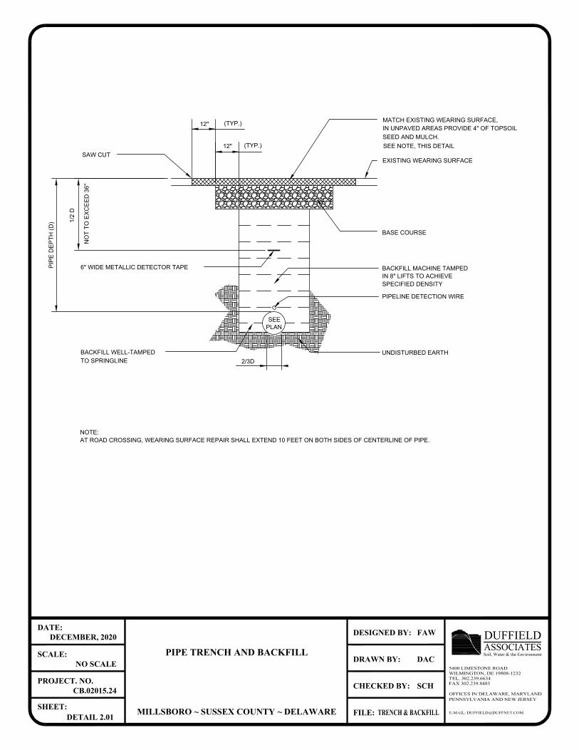
6" WIDE METALLIC DETECTOR TAPE
BACKFILL WELL-TAMPED
TO SPRINGLINE
SAW CUT
12"
UNDISTURBED EARTH
2/3D
SEE
PLAN
SPECIFIED DENSITY
IN 8" LIFTS TO ACHIEVE
BACKFILL MACHINE TAMPED
SEED AND MULCH.
IN UNPAVED AREAS PROVIDE 4" OF TOPSOIL
MATCH EXISTING WEARING SURFACE,
EXISTING WEARING SURFACE
12"
(TYP.)
(TYP.)
BASE COURSE
E-MAIL: [email protected]
OFFICES IN DELAWARE, MARYLANDPENNSYLVANIA AND NEW JERSEY
CHECKED BY:
DRAWN BY:
FILE:
DESIGNED BY:
SHEET:
PROJECT. NO.
SCALE:
DATE:
ASSOCIATESDUFFIELDSoil, Water & the Environment
5400 LIMESTONE ROADWILMINGTON, DE 19808-1232TEL. 302.239.6634FAX 302.239.8485
PIPE TRENCH AND BACKFILL
MILLSBORO ~ SUSSEX COUNTY ~ DELAWARE
DECEMBER, 2020
NO SCALE
CB.02015.24
DETAIL 2.01
FAW
DAC
SCH
TRENCH & BACKFILL
PIPELINE DETECTION WIRE
NO
T T
O E
XC
EE
D 36"
NOTE:
AT ROAD CROSSING, WEARING SURFACE REPAIR SHALL EXTEND 10 FEET ON BOTH SIDES OF CENTERLINE OF PIPE.
1/2 D
SEE NOTE, THIS DETAIL
PIP
E D
EP
TH
(D
)
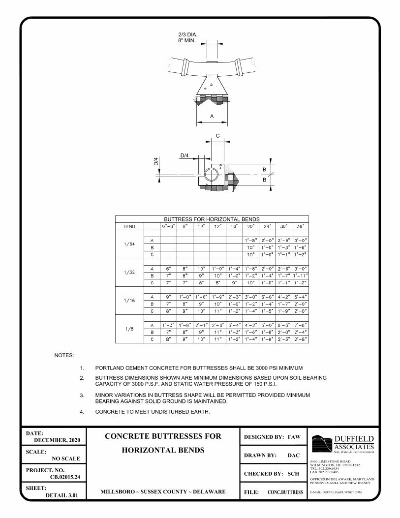
PORTLAND CEMENT CONCRETE FOR BUTTRESSES SHALL BE 3000 PSI MINIMUM
BUTTRESS DIMENSIONS SHOWN ARE MINIMUM DIMENSIONS BASED UPON SOIL BEARING
CAPACITY OF 3000 P.S.F. AND STATIC WATER PRESSURE OF 150 P.S.I.
MINOR VARIATIONS IN BUTTRESS SHAPE WILL BE PERMITTED PROVIDED MINIMUM
BEARING AGAINST SOLID GROUND IS MAINTAINED.
CONCRETE TO MEET UNDISTURBED EARTH. 4.
1.
2.
3.
NOTES:
A
BUTTRESS FOR HORIZONTAL BENDS
D/4
B
B
C
D/4
2/3 DIA.
8" MIN.
E-MAIL: [email protected]
OFFICES IN DELAWARE, MARYLANDPENNSYLVANIA AND NEW JERSEY
CHECKED BY:
DRAWN BY:
FILE:
DESIGNED BY:
SHEET:
PROJECT. NO.
SCALE:
DATE:
ASSOCIATESDUFFIELDSoil, Water & the Environment
5400 LIMESTONE ROADWILMINGTON, DE 19808-1232TEL. 302.239.6634FAX 302.239.8485
CONCRETE BUTTRESSES FOR
HORIZONTAL BENDS
MILLSBORO ~ SUSSEX COUNTY ~ DELAWARE
DECEMBER, 2020
NO SCALE
CB.02015.24
DETAIL 3.01
FAW
DAC
SCH
CONC.BUTTRESS
AutoCAD SHX Text
2'-6"
AutoCAD SHX Text
C
AutoCAD SHX Text
8"
AutoCAD SHX Text
9"
AutoCAD SHX Text
10"
AutoCAD SHX Text
1'-3"
AutoCAD SHX Text
1/8
AutoCAD SHX Text
B
AutoCAD SHX Text
A
AutoCAD SHX Text
1'-8"
AutoCAD SHX Text
7"
AutoCAD SHX Text
2'-1"
AutoCAD SHX Text
9"
AutoCAD SHX Text
8"
AutoCAD SHX Text
7'-6"
AutoCAD SHX Text
2'-4"
AutoCAD SHX Text
2'-8"
AutoCAD SHX Text
11"
AutoCAD SHX Text
1'-2"
AutoCAD SHX Text
1'-4"
AutoCAD SHX Text
1'-9"
AutoCAD SHX Text
2'-3"
AutoCAD SHX Text
11"
AutoCAD SHX Text
3'-4"
AutoCAD SHX Text
1'-3"
AutoCAD SHX Text
4'-2"
AutoCAD SHX Text
1'-6"
AutoCAD SHX Text
5'-0"
AutoCAD SHX Text
1'-8"
AutoCAD SHX Text
6'-3"
AutoCAD SHX Text
2'-0"
AutoCAD SHX Text
1/32
AutoCAD SHX Text
1/16
AutoCAD SHX Text
B
AutoCAD SHX Text
C
AutoCAD SHX Text
A
AutoCAD SHX Text
8"
AutoCAD SHX Text
7"
AutoCAD SHX Text
8"
AutoCAD SHX Text
9"
AutoCAD SHX Text
10"
AutoCAD SHX Text
9"
AutoCAD SHX Text
9"
AutoCAD SHX Text
1'-0"
AutoCAD SHX Text
1'-6"
AutoCAD SHX Text
C
AutoCAD SHX Text
B
AutoCAD SHX Text
7"
AutoCAD SHX Text
7"
AutoCAD SHX Text
8"
AutoCAD SHX Text
7"
AutoCAD SHX Text
9"
AutoCAD SHX Text
8"
AutoCAD SHX Text
A
AutoCAD SHX Text
C
AutoCAD SHX Text
6"
AutoCAD SHX Text
8"
AutoCAD SHX Text
10"
AutoCAD SHX Text
1/64
AutoCAD SHX Text
B
AutoCAD SHX Text
A
AutoCAD SHX Text
1'-11"
AutoCAD SHX Text
2'-0"
AutoCAD SHX Text
5'-4"
AutoCAD SHX Text
11"
AutoCAD SHX Text
10"
AutoCAD SHX Text
1'-4"
AutoCAD SHX Text
1'-2"
AutoCAD SHX Text
1'-0"
AutoCAD SHX Text
1'-2"
AutoCAD SHX Text
2'-3"
AutoCAD SHX Text
1'-9"
AutoCAD SHX Text
3'-0"
AutoCAD SHX Text
1'-5"
AutoCAD SHX Text
1'-4"
AutoCAD SHX Text
1'-7"
AutoCAD SHX Text
1'-9"
AutoCAD SHX Text
2'-0"
AutoCAD SHX Text
4'-2"
AutoCAD SHX Text
3'-6"
AutoCAD SHX Text
8"
AutoCAD SHX Text
9"
AutoCAD SHX Text
10"
AutoCAD SHX Text
1'-0"
AutoCAD SHX Text
10"
AutoCAD SHX Text
1'-2"
AutoCAD SHX Text
1'-0"
AutoCAD SHX Text
1'-1"
AutoCAD SHX Text
1'-2"
AutoCAD SHX Text
1'-4"
AutoCAD SHX Text
1'-7"
AutoCAD SHX Text
3'-0"
AutoCAD SHX Text
3'-0"
AutoCAD SHX Text
1'-0"
AutoCAD SHX Text
1'-4"
AutoCAD SHX Text
1'-8"
AutoCAD SHX Text
10"
AutoCAD SHX Text
2'-0"
AutoCAD SHX Text
2'-6"
AutoCAD SHX Text
1'-1"
AutoCAD SHX Text
1'-0"
AutoCAD SHX Text
1'-2"
AutoCAD SHX Text
10"
AutoCAD SHX Text
1'-8"
AutoCAD SHX Text
2'-0"
AutoCAD SHX Text
1'-0"
AutoCAD SHX Text
1'-3"
AutoCAD SHX Text
2'-6"
AutoCAD SHX Text
1'-6"
AutoCAD SHX Text
0"-6"
AutoCAD SHX Text
BEND
AutoCAD SHX Text
8"
AutoCAD SHX Text
10"
AutoCAD SHX Text
12"
AutoCAD SHX Text
16"
AutoCAD SHX Text
20"
AutoCAD SHX Text
24"
AutoCAD SHX Text
30"
AutoCAD SHX Text
36"
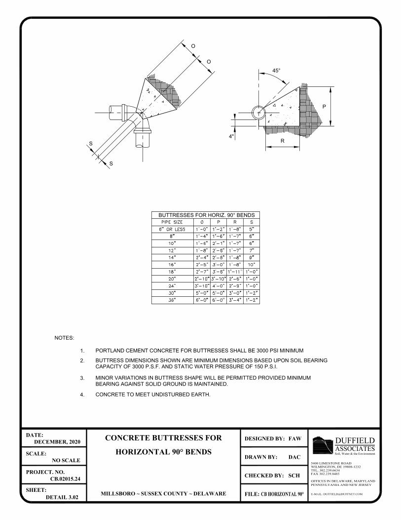
MINOR VARIATIONS IN BUTTRESS SHAPE WILL BE PERMITTED PROVIDED MINIMUM
BEARING AGAINST SOLID GROUND IS MAINTAINED.
CONCRETE TO MEET UNDISTURBED EARTH. 4.
3.
PORTLAND CEMENT CONCRETE FOR BUTTRESSES SHALL BE 3000 PSI MINIMUM
BUTTRESS DIMENSIONS SHOWN ARE MINIMUM DIMENSIONS BASED UPON SOIL BEARING
CAPACITY OF 3000 P.S.F. AND STATIC WATER PRESSURE OF 150 P.S.I.
1.
2.
NOTES:
P
R
4"
BUTTRESSES FOR HORIZ. 90° BENDS
45°
O
O
S
S
E-MAIL: [email protected]
OFFICES IN DELAWARE, MARYLANDPENNSYLVANIA AND NEW JERSEY
CHECKED BY:
DRAWN BY:
FILE:
DESIGNED BY:
SHEET:
PROJECT. NO.
SCALE:
DATE:
ASSOCIATESDUFFIELDSoil, Water & the Environment
5400 LIMESTONE ROADWILMINGTON, DE 19808-1232TEL. 302.239.6634FAX 302.239.8485
CONCRETE BUTTRESSES FOR
HORIZONTAL 90° BENDS
MILLSBORO ~ SUSSEX COUNTY ~ DELAWARE
DECEMBER, 2020
NO SCALE
CB.02015.24
DETAIL 3.02
FAW
DAC
SCH
CB HORIZONTAL 90°
AutoCAD SHX Text
16"
AutoCAD SHX Text
14"
AutoCAD SHX Text
12"
AutoCAD SHX Text
2'-4"
AutoCAD SHX Text
1'-8"
AutoCAD SHX Text
2'-5"
AutoCAD SHX Text
2'-6"
AutoCAD SHX Text
2'-6"
AutoCAD SHX Text
3'-0"
AutoCAD SHX Text
1'-7"
AutoCAD SHX Text
1'-8"
AutoCAD SHX Text
1'-8"
AutoCAD SHX Text
10"
AutoCAD SHX Text
8"
AutoCAD SHX Text
6" OR LESS
AutoCAD SHX Text
1'-0"
AutoCAD SHX Text
1'-2"
AutoCAD SHX Text
1'-8"
AutoCAD SHX Text
1'-4"
AutoCAD SHX Text
1'-6"
AutoCAD SHX Text
1'-6"
AutoCAD SHX Text
2'-1"
AutoCAD SHX Text
1'-7"
AutoCAD SHX Text
1'-7"
AutoCAD SHX Text
7"
AutoCAD SHX Text
10"
AutoCAD SHX Text
9"
AutoCAD SHX Text
5"
AutoCAD SHX Text
6"
AutoCAD SHX Text
6"
AutoCAD SHX Text
PIPE SIZE
AutoCAD SHX Text
R
AutoCAD SHX Text
P
AutoCAD SHX Text
O
AutoCAD SHX Text
S
AutoCAD SHX Text
36"
AutoCAD SHX Text
30"
AutoCAD SHX Text
24"
AutoCAD SHX Text
20"
AutoCAD SHX Text
18"
AutoCAD SHX Text
1'-0"
AutoCAD SHX Text
1'-11"
AutoCAD SHX Text
3'-6"
AutoCAD SHX Text
2'-7"
AutoCAD SHX Text
5'-0"
AutoCAD SHX Text
6'-0"
AutoCAD SHX Text
5'-0"
AutoCAD SHX Text
6'-0"
AutoCAD SHX Text
3'-0"
AutoCAD SHX Text
3'-4"
AutoCAD SHX Text
1'-2"
AutoCAD SHX Text
1'-2"
AutoCAD SHX Text
3'-10"
AutoCAD SHX Text
4'-0"
AutoCAD SHX Text
2'-10"
AutoCAD SHX Text
3'-10"
AutoCAD SHX Text
2'-6"
AutoCAD SHX Text
1'-0"
AutoCAD SHX Text
2'-9"
AutoCAD SHX Text
1'-0"

D
MINOR VARIATIONS IN BUTTRESS SHAPE WILL BE PERMITTED PROVIDED MINIMUM
CONCRETE TO MEET UNDISTURBED EARTH.
BEARING AGAINST SOLID GROUND IS MAINTAINED.
4.
3.
CAPACITY OF 3000 P.S.F. AND STATIC WATER PRESSURE OF 150 P.S.I.
BUTTRESS DIMENSIONS SHOWN ARE MINIMUM DIMENSIONS BASED UPON SOIL BEARING
PORTLAND CEMENT CONCRETE FOR BUTTRESSES SHALL BE 3000 PSI MINIMUM
2.
1.
NOTES:
I
I
H
BUTTRESS FOR TEES
D/4
D/4
4" M
IN
.
J
J
K
K
E-MAIL: [email protected]
OFFICES IN DELAWARE, MARYLANDPENNSYLVANIA AND NEW JERSEY
CHECKED BY:
DRAWN BY:
FILE:
DESIGNED BY:
SHEET:
PROJECT. NO.
SCALE:
DATE:
ASSOCIATESDUFFIELDSoil, Water & the Environment
5400 LIMESTONE ROADWILMINGTON, DE 19808-1232TEL. 302.239.6634FAX 302.239.8485
CONCRETE BUTTRESSES FOR
HORIZONTAL TEES
MILLSBORO ~ SUSSEX COUNTY ~ DELAWARE
DECEMBER, 2020
NO SCALE
CB.02015.24
DETAIL 3.03
FAW
DAC
SCH
CONC.BUTTRESS TEES
AutoCAD SHX Text
2'-1"
AutoCAD SHX Text
1'-8"
AutoCAD SHX Text
1'-4"
AutoCAD SHX Text
20"
AutoCAD SHX Text
16"
AutoCAD SHX Text
12"
AutoCAD SHX Text
8"
AutoCAD SHX Text
10"
AutoCAD SHX Text
PIPE DIA.
AutoCAD SHX Text
D
AutoCAD SHX Text
J
AutoCAD SHX Text
H
AutoCAD SHX Text
I
AutoCAD SHX Text
1'-4"
AutoCAD SHX Text
1'-0"
AutoCAD SHX Text
8"
AutoCAD SHX Text
6"
AutoCAD SHX Text
1'-0"
AutoCAD SHX Text
1'-0"
AutoCAD SHX Text
9"
AutoCAD SHX Text
8"
AutoCAD SHX Text
10"
AutoCAD SHX Text
10"
AutoCAD SHX Text
8"
AutoCAD SHX Text
1'-2"
AutoCAD SHX Text
1'-0"
AutoCAD SHX Text
1'-8"
AutoCAD SHX Text
1'-3"
AutoCAD SHX Text
24"
AutoCAD SHX Text
30"
AutoCAD SHX Text
36"
AutoCAD SHX Text
2'-6"
AutoCAD SHX Text
2'-0"
AutoCAD SHX Text
3'-0"
AutoCAD SHX Text
2'-0"
AutoCAD SHX Text
3'-9"
AutoCAD SHX Text
1'-9"
AutoCAD SHX Text
1'-6"
AutoCAD SHX Text
3'-1"
AutoCAD SHX Text
2'-6"
AutoCAD SHX Text
10"
AutoCAD SHX Text
K
AutoCAD SHX Text
8"
AutoCAD SHX Text
6"
AutoCAD SHX Text
8"
AutoCAD SHX Text
8"
AutoCAD SHX Text
1'-10"
AutoCAD SHX Text
1'-4"
AutoCAD SHX Text
1'-6"
AutoCAD SHX Text
1'-2"
AutoCAD SHX Text
0"-6"
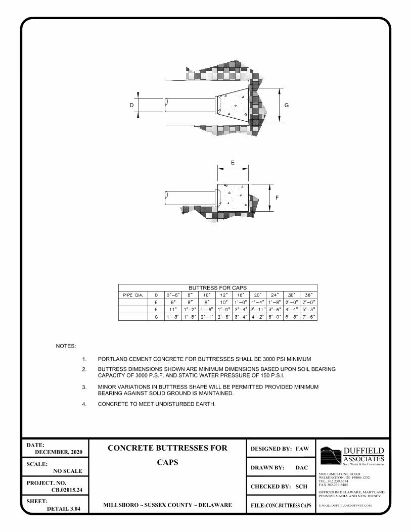
MINOR VARIATIONS IN BUTTRESS SHAPE WILL BE PERMITTED PROVIDED MINIMUM
BEARING AGAINST SOLID GROUND IS MAINTAINED.
CONCRETE TO MEET UNDISTURBED EARTH. 4.
3.
PORTLAND CEMENT CONCRETE FOR BUTTRESSES SHALL BE 3000 PSI MINIMUM
BUTTRESS DIMENSIONS SHOWN ARE MINIMUM DIMENSIONS BASED UPON SOIL BEARING
CAPACITY OF 3000 P.S.F. AND STATIC WATER PRESSURE OF 150 P.S.I.
1.
2.
NOTES:
G
F
E
D
BUTTRESS FOR CAPS
E-MAIL: [email protected]
OFFICES IN DELAWARE, MARYLANDPENNSYLVANIA AND NEW JERSEY
CHECKED BY:
DRAWN BY:
FILE:
DESIGNED BY:
SHEET:
PROJECT. NO.
SCALE:
DATE:
ASSOCIATESDUFFIELDSoil, Water & the Environment
5400 LIMESTONE ROADWILMINGTON, DE 19808-1232TEL. 302.239.6634FAX 302.239.8485
CONCRETE BUTTRESSES FOR
CAPS
MILLSBORO ~ SUSSEX COUNTY ~ DELAWARE
DECEMBER, 2020
NO SCALE
CB.02015.24
DETAIL 3.04
FAW
DAC
SCH
CONC.BUTTRESS CAPS
AutoCAD SHX Text
E
AutoCAD SHX Text
6"
AutoCAD SHX Text
8"
AutoCAD SHX Text
F
AutoCAD SHX Text
G
AutoCAD SHX Text
11"
AutoCAD SHX Text
1'-3"
AutoCAD SHX Text
1'-2"
AutoCAD SHX Text
1'-8"
AutoCAD SHX Text
8"
AutoCAD SHX Text
10"
AutoCAD SHX Text
1'-6"
AutoCAD SHX Text
2'-1"
AutoCAD SHX Text
1'-9"
AutoCAD SHX Text
2'-6"
AutoCAD SHX Text
PIPE DIA.
AutoCAD SHX Text
8"
AutoCAD SHX Text
D
AutoCAD SHX Text
10"
AutoCAD SHX Text
12"
AutoCAD SHX Text
5'-0"
AutoCAD SHX Text
3'-6"
AutoCAD SHX Text
4'-2"
AutoCAD SHX Text
2'-11"
AutoCAD SHX Text
7'-6"
AutoCAD SHX Text
6'-3"
AutoCAD SHX Text
4'-4"
AutoCAD SHX Text
5'-3"
AutoCAD SHX Text
1'-8"
AutoCAD SHX Text
24"
AutoCAD SHX Text
1'-4"
AutoCAD SHX Text
20"
AutoCAD SHX Text
2'-0"
AutoCAD SHX Text
36"
AutoCAD SHX Text
2'-0"
AutoCAD SHX Text
30"
AutoCAD SHX Text
16"
AutoCAD SHX Text
1'-0"
AutoCAD SHX Text
2'-4"
AutoCAD SHX Text
3'-4"
AutoCAD SHX Text
0"-6"
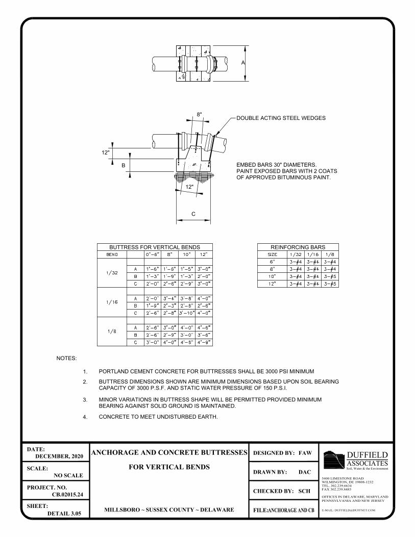
A
MINOR VARIATIONS IN BUTTRESS SHAPE WILL BE PERMITTED PROVIDED MINIMUM
BEARING AGAINST SOLID GROUND IS MAINTAINED.
CONCRETE TO MEET UNDISTURBED EARTH. 4.
3.
PORTLAND CEMENT CONCRETE FOR BUTTRESSES SHALL BE 3000 PSI MINIMUM
BUTTRESS DIMENSIONS SHOWN ARE MINIMUM DIMENSIONS BASED UPON SOIL BEARING
CAPACITY OF 3000 P.S.F. AND STATIC WATER PRESSURE OF 150 P.S.I.
1.
2.
NOTES:
REINFORCING BARSBUTTRESS FOR VERTICAL BENDS
B
12"
C
EMBED BARS 30" DIAMETERS.
PAINT EXPOSED BARS WITH 2 COATS
OF APPROVED BITUMINOUS PAINT.
DOUBLE ACTING STEEL WEDGES
12"
8"
E-MAIL: [email protected]
OFFICES IN DELAWARE, MARYLANDPENNSYLVANIA AND NEW JERSEY
CHECKED BY:
DRAWN BY:
FILE:
DESIGNED BY:
SHEET:
PROJECT. NO.
SCALE:
DATE:
ASSOCIATESDUFFIELDSoil, Water & the Environment
5400 LIMESTONE ROADWILMINGTON, DE 19808-1232TEL. 302.239.6634FAX 302.239.8485
ANCHORAGE AND CONCRETE BUTTRESSES
FOR VERTICAL BENDS
MILLSBORO ~ SUSSEX COUNTY ~ DELAWARE
DECEMBER, 2020
NO SCALE
CB.02015.24
DETAIL 3.05
FAW
DAC
SCH
ANCHORAGE AND CB
AutoCAD SHX Text
12"
AutoCAD SHX Text
3-#5
AutoCAD SHX Text
10"
AutoCAD SHX Text
8"
AutoCAD SHX Text
6"
AutoCAD SHX Text
3-#4
AutoCAD SHX Text
3-#5
AutoCAD SHX Text
SIZE
AutoCAD SHX Text
1/8
AutoCAD SHX Text
1/16
AutoCAD SHX Text
1/32
AutoCAD SHX Text
3-#4
AutoCAD SHX Text
3-#4
AutoCAD SHX Text
3-#4
AutoCAD SHX Text
3-#4
AutoCAD SHX Text
3-#4
AutoCAD SHX Text
3-#4
AutoCAD SHX Text
3-#4
AutoCAD SHX Text
3-#4
AutoCAD SHX Text
3-#4
AutoCAD SHX Text
1/16
AutoCAD SHX Text
1/8
AutoCAD SHX Text
B
AutoCAD SHX Text
C
AutoCAD SHX Text
A
AutoCAD SHX Text
3'-0"
AutoCAD SHX Text
2'-6"
AutoCAD SHX Text
2'-9"
AutoCAD SHX Text
4'-0"
AutoCAD SHX Text
4'-6"
AutoCAD SHX Text
3'-0"
AutoCAD SHX Text
2'-6"
AutoCAD SHX Text
3'-0"
AutoCAD SHX Text
4'-0"
AutoCAD SHX Text
C
AutoCAD SHX Text
B
AutoCAD SHX Text
2'-6"
AutoCAD SHX Text
2'-8"
AutoCAD SHX Text
3'-10"
AutoCAD SHX Text
1'-9"
AutoCAD SHX Text
2'-6"
AutoCAD SHX Text
2'-3"
AutoCAD SHX Text
A
AutoCAD SHX Text
C
AutoCAD SHX Text
2'-0"
AutoCAD SHX Text
3'-4"
AutoCAD SHX Text
3'-8"
AutoCAD SHX Text
1/32
AutoCAD SHX Text
B
AutoCAD SHX Text
A
AutoCAD SHX Text
4'-9"
AutoCAD SHX Text
3'-6"
AutoCAD SHX Text
4'-6"
AutoCAD SHX Text
4'-0"
AutoCAD SHX Text
2'-6"
AutoCAD SHX Text
4'-0"
AutoCAD SHX Text
0"-6"
AutoCAD SHX Text
BEND
AutoCAD SHX Text
8"
AutoCAD SHX Text
10"
AutoCAD SHX Text
12"
AutoCAD SHX Text
2'-6"
AutoCAD SHX Text
2'-9"
AutoCAD SHX Text
1'-3"
AutoCAD SHX Text
1'-9"
AutoCAD SHX Text
2'-0"
AutoCAD SHX Text
1'-3"
AutoCAD SHX Text
3'-0"
AutoCAD SHX Text
2'-0"
AutoCAD SHX Text
1'-6"
AutoCAD SHX Text
1'-5"
AutoCAD SHX Text
1'-6"
AutoCAD SHX Text
3'-0"
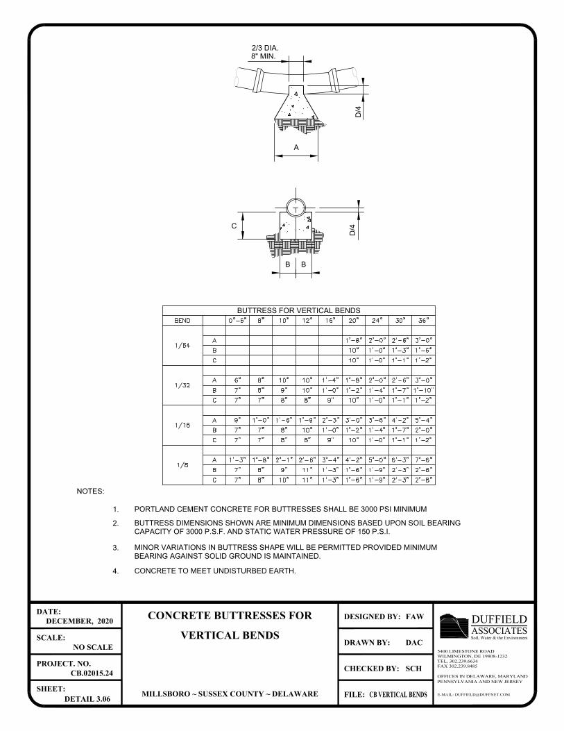
MINOR VARIATIONS IN BUTTRESS SHAPE WILL BE PERMITTED PROVIDED MINIMUM
CONCRETE TO MEET UNDISTURBED EARTH.
BEARING AGAINST SOLID GROUND IS MAINTAINED.
4.
3.
CAPACITY OF 3000 P.S.F. AND STATIC WATER PRESSURE OF 150 P.S.I.
BUTTRESS DIMENSIONS SHOWN ARE MINIMUM DIMENSIONS BASED UPON SOIL BEARING
PORTLAND CEMENT CONCRETE FOR BUTTRESSES SHALL BE 3000 PSI MINIMUM
2.
1.
NOTES:
BUTTRESS FOR VERTICAL BENDS
C
D/4
B B
A
2/3 DIA.
8" MIN.
D/4
E-MAIL: [email protected]
OFFICES IN DELAWARE, MARYLANDPENNSYLVANIA AND NEW JERSEY
CHECKED BY:
DRAWN BY:
FILE:
DESIGNED BY:
SHEET:
PROJECT. NO.
SCALE:
DATE:
ASSOCIATESDUFFIELDSoil, Water & the Environment
5400 LIMESTONE ROADWILMINGTON, DE 19808-1232TEL. 302.239.6634FAX 302.239.8485
CONCRETE BUTTRESSES FOR
VERTICAL BENDS
MILLSBORO ~ SUSSEX COUNTY ~ DELAWARE
DECEMBER, 2020
NO SCALE
CB.02015.24
DETAIL 3.06
FAW
DAC
SCH
CB VERTICAL BENDS
AutoCAD SHX Text
8"
AutoCAD SHX Text
9"
AutoCAD SHX Text
10"
AutoCAD SHX Text
1'-0"
AutoCAD SHX Text
1'-1"
AutoCAD SHX Text
1'-2"
AutoCAD SHX Text
8"
AutoCAD SHX Text
7"
AutoCAD SHX Text
7"
AutoCAD SHX Text
1'-2"
AutoCAD SHX Text
7"
AutoCAD SHX Text
7"
AutoCAD SHX Text
8"
AutoCAD SHX Text
10"
AutoCAD SHX Text
1'-0"
AutoCAD SHX Text
2'-0"
AutoCAD SHX Text
1'-4"
AutoCAD SHX Text
1'-7"
AutoCAD SHX Text
3'-0"
AutoCAD SHX Text
1'-6"
AutoCAD SHX Text
1'-0"
AutoCAD SHX Text
9"
AutoCAD SHX Text
2'-3"
AutoCAD SHX Text
1'-9"
AutoCAD SHX Text
5'-4"
AutoCAD SHX Text
4'-2"
AutoCAD SHX Text
3'-6"
AutoCAD SHX Text
A
AutoCAD SHX Text
B
AutoCAD SHX Text
C
AutoCAD SHX Text
1/16
AutoCAD SHX Text
C
AutoCAD SHX Text
B
AutoCAD SHX Text
A
AutoCAD SHX Text
C
AutoCAD SHX Text
B
AutoCAD SHX Text
A
AutoCAD SHX Text
1/32
AutoCAD SHX Text
1/64
AutoCAD SHX Text
1'-8"
AutoCAD SHX Text
10"
AutoCAD SHX Text
10"
AutoCAD SHX Text
3'-0"
AutoCAD SHX Text
1'-6"
AutoCAD SHX Text
1'-2"
AutoCAD SHX Text
2'-0"
AutoCAD SHX Text
2'-6"
AutoCAD SHX Text
1'-3"
AutoCAD SHX Text
1'-0"
AutoCAD SHX Text
1'-0"
AutoCAD SHX Text
1'-1"
AutoCAD SHX Text
20"
AutoCAD SHX Text
0"-6"
AutoCAD SHX Text
8"
AutoCAD SHX Text
10"
AutoCAD SHX Text
12"
AutoCAD SHX Text
16"
AutoCAD SHX Text
36"
AutoCAD SHX Text
24"
AutoCAD SHX Text
30"
AutoCAD SHX Text
BEND
AutoCAD SHX Text
4'-2"
AutoCAD SHX Text
1'-6"
AutoCAD SHX Text
1'-6"
AutoCAD SHX Text
1/8
AutoCAD SHX Text
C
AutoCAD SHX Text
B
AutoCAD SHX Text
A
AutoCAD SHX Text
1'-3"
AutoCAD SHX Text
1'-8"
AutoCAD SHX Text
2'-1"
AutoCAD SHX Text
9"
AutoCAD SHX Text
8"
AutoCAD SHX Text
7"
AutoCAD SHX Text
7"
AutoCAD SHX Text
8"
AutoCAD SHX Text
10"
AutoCAD SHX Text
2'-6"
AutoCAD SHX Text
3'-4"
AutoCAD SHX Text
1'-3"
AutoCAD SHX Text
11"
AutoCAD SHX Text
11"
AutoCAD SHX Text
1'-3"
AutoCAD SHX Text
7'-6"
AutoCAD SHX Text
2'-6"
AutoCAD SHX Text
2'-8"
AutoCAD SHX Text
5'-0"
AutoCAD SHX Text
6'-3"
AutoCAD SHX Text
2'-3"
AutoCAD SHX Text
1'-9"
AutoCAD SHX Text
1'-9"
AutoCAD SHX Text
2'-3"
AutoCAD SHX Text
1'-8"
AutoCAD SHX Text
1'-2"
AutoCAD SHX Text
10"
AutoCAD SHX Text
6"
AutoCAD SHX Text
8"
AutoCAD SHX Text
10"
AutoCAD SHX Text
9"
AutoCAD SHX Text
8"
AutoCAD SHX Text
7"
AutoCAD SHX Text
7"
AutoCAD SHX Text
7"
AutoCAD SHX Text
8"
AutoCAD SHX Text
10"
AutoCAD SHX Text
1'-4"
AutoCAD SHX Text
1'-0"
AutoCAD SHX Text
10"
AutoCAD SHX Text
8"
AutoCAD SHX Text
9"
AutoCAD SHX Text
3'-0"
AutoCAD SHX Text
1'-10"
AutoCAD SHX Text
1'-2"
AutoCAD SHX Text
2'-0"
AutoCAD SHX Text
2'-6"
AutoCAD SHX Text
1'-7"
AutoCAD SHX Text
1'-4"
AutoCAD SHX Text
1'-0"
AutoCAD SHX Text
1'-1"
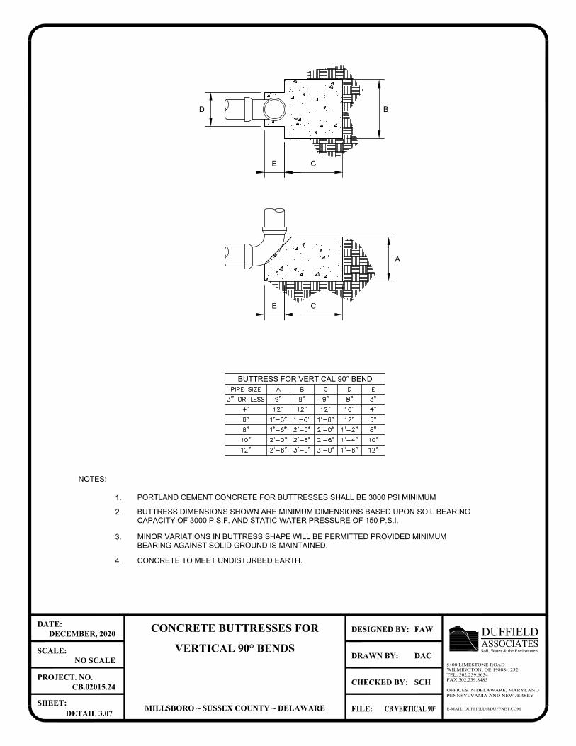
MINOR VARIATIONS IN BUTTRESS SHAPE WILL BE PERMITTED PROVIDED MINIMUM
BEARING AGAINST SOLID GROUND IS MAINTAINED.
CONCRETE TO MEET UNDISTURBED EARTH. 4.
3.
PORTLAND CEMENT CONCRETE FOR BUTTRESSES SHALL BE 3000 PSI MINIMUM
BUTTRESS DIMENSIONS SHOWN ARE MINIMUM DIMENSIONS BASED UPON SOIL BEARING
CAPACITY OF 3000 P.S.F. AND STATIC WATER PRESSURE OF 150 P.S.I.
1.
2.
NOTES:
B
E C
CE
D
A
BUTTRESS FOR VERTICAL 90° BEND
E-MAIL: [email protected]
OFFICES IN DELAWARE, MARYLANDPENNSYLVANIA AND NEW JERSEY
CHECKED BY:
DRAWN BY:
FILE:
DESIGNED BY:
SHEET:
PROJECT. NO.
SCALE:
DATE:
ASSOCIATESDUFFIELDSoil, Water & the Environment
5400 LIMESTONE ROADWILMINGTON, DE 19808-1232TEL. 302.239.6634FAX 302.239.8485
CONCRETE BUTTRESSES FOR
VERTICAL 90° BENDS
MILLSBORO ~ SUSSEX COUNTY ~ DELAWARE
DECEMBER, 2020
NO SCALE
CB.02015.24
DETAIL 3.07
FAW
DAC
SCH
CB VERTICAL 90°
AutoCAD SHX Text
12"
AutoCAD SHX Text
10"
AutoCAD SHX Text
8"
AutoCAD SHX Text
6"
AutoCAD SHX Text
4"
AutoCAD SHX Text
3"
AutoCAD SHX Text
1'-4"
AutoCAD SHX Text
1'-6"
AutoCAD SHX Text
12"
AutoCAD SHX Text
1'-2"
AutoCAD SHX Text
8"
AutoCAD SHX Text
10"
AutoCAD SHX Text
3'-0"
AutoCAD SHX Text
2'-6"
AutoCAD SHX Text
2'-0"
AutoCAD SHX Text
1'-6"
AutoCAD SHX Text
12"
AutoCAD SHX Text
9"
AutoCAD SHX Text
3'-0"
AutoCAD SHX Text
2'-6"
AutoCAD SHX Text
2'-0"
AutoCAD SHX Text
1'-6"
AutoCAD SHX Text
12"
AutoCAD SHX Text
9"
AutoCAD SHX Text
2'-6"
AutoCAD SHX Text
1'-6"
AutoCAD SHX Text
1'-6"
AutoCAD SHX Text
2'-0"
AutoCAD SHX Text
9"
AutoCAD SHX Text
12"
AutoCAD SHX Text
3" OR LESS
AutoCAD SHX Text
4"
AutoCAD SHX Text
6"
AutoCAD SHX Text
8"
AutoCAD SHX Text
10"
AutoCAD SHX Text
12"
AutoCAD SHX Text
PIPE SIZE
AutoCAD SHX Text
A
AutoCAD SHX Text
B
AutoCAD SHX Text
C
AutoCAD SHX Text
E
AutoCAD SHX Text
D
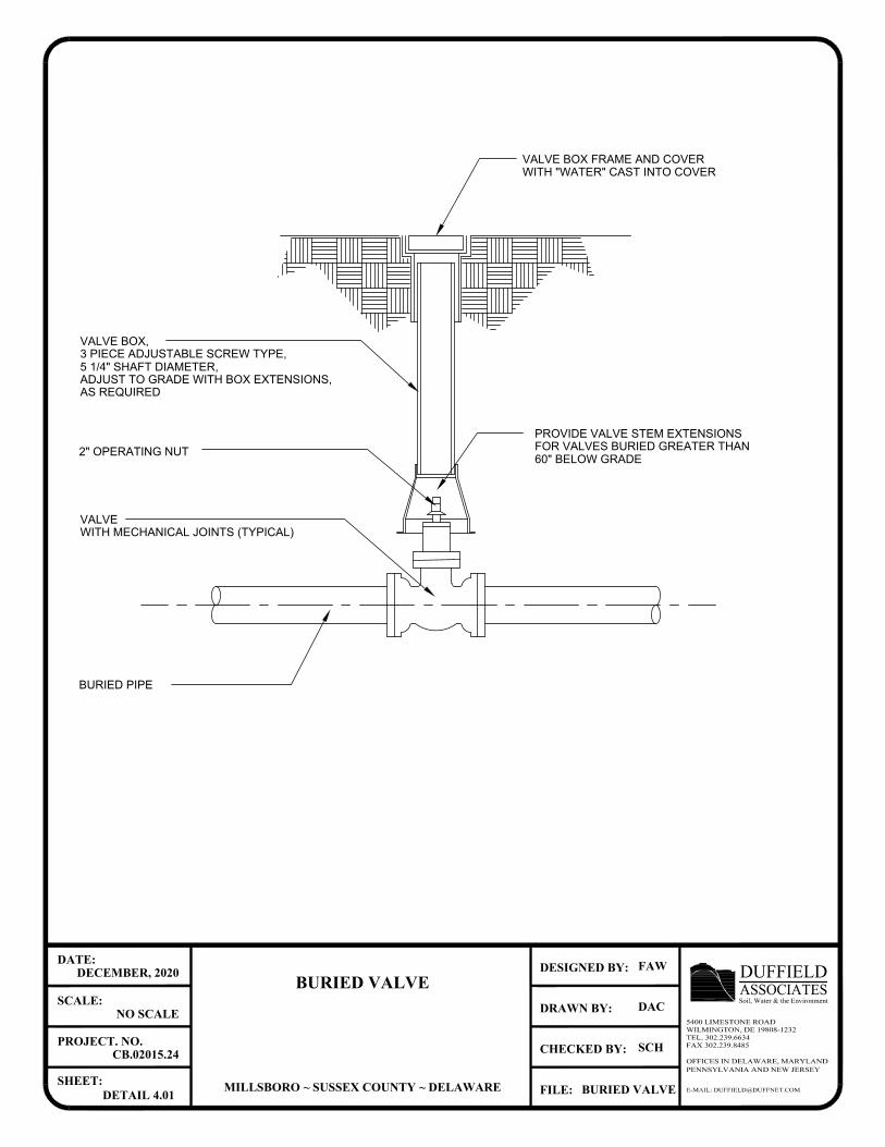
AS REQUIRED
ADJUST TO GRADE WITH BOX EXTENSIONS,
5 1/4" SHAFT DIAMETER,
3 PIECE ADJUSTABLE SCREW TYPE,
VALVE BOX,
WITH "WATER" CAST INTO COVER
VALVE BOX FRAME AND COVER
2" OPERATING NUT
VALVE
WITH MECHANICAL JOINTS (TYPICAL)
BURIED PIPE
E-MAIL: [email protected]
OFFICES IN DELAWARE, MARYLANDPENNSYLVANIA AND NEW JERSEY
CHECKED BY:
DRAWN BY:
FILE:
DESIGNED BY:
SHEET:
PROJECT. NO.
SCALE:
DATE:
ASSOCIATESDUFFIELDSoil, Water & the Environment
5400 LIMESTONE ROADWILMINGTON, DE 19808-1232TEL. 302.239.6634FAX 302.239.8485
BURIED VALVE
MILLSBORO ~ SUSSEX COUNTY ~ DELAWARE
DECEMBER, 2020
NO SCALE
CB.02015.24
DETAIL 4.01
FAW
DAC
SCH
BURIED VALVE
60" BELOW GRADE
FOR VALVES BURIED GREATER THAN
PROVIDE VALVE STEM EXTENSIONS
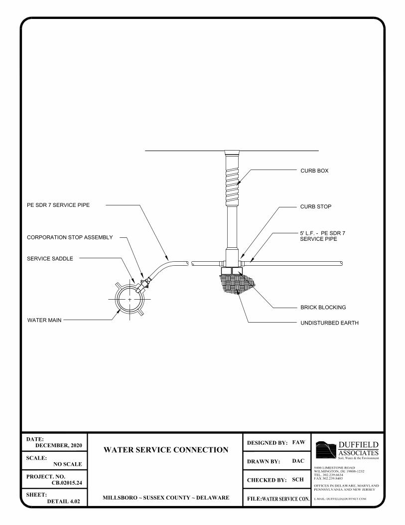
CORPORATION STOP ASSEMBLY
SERVICE SADDLE
WATER MAIN
PE SDR 7 SERVICE PIPE
SERVICE PIPE
BRICK BLOCKING
UNDISTURBED EARTH
CURB STOP
CURB BOX
E-MAIL: [email protected]
OFFICES IN DELAWARE, MARYLANDPENNSYLVANIA AND NEW JERSEY
CHECKED BY:
DRAWN BY:
FILE:
DESIGNED BY:
SHEET:
PROJECT. NO.
SCALE:
DATE:
ASSOCIATESDUFFIELDSoil, Water & the Environment
5400 LIMESTONE ROADWILMINGTON, DE 19808-1232TEL. 302.239.6634FAX 302.239.8485
WATER SERVICE CONNECTION
MILLSBORO ~ SUSSEX COUNTY ~ DELAWARE
DECEMBER, 2020
NO SCALE
CB.02015.24
DETAIL 4.02
FAW
DAC
SCH
WATER SERVICE CON.
5' L.F. - PE SDR 7
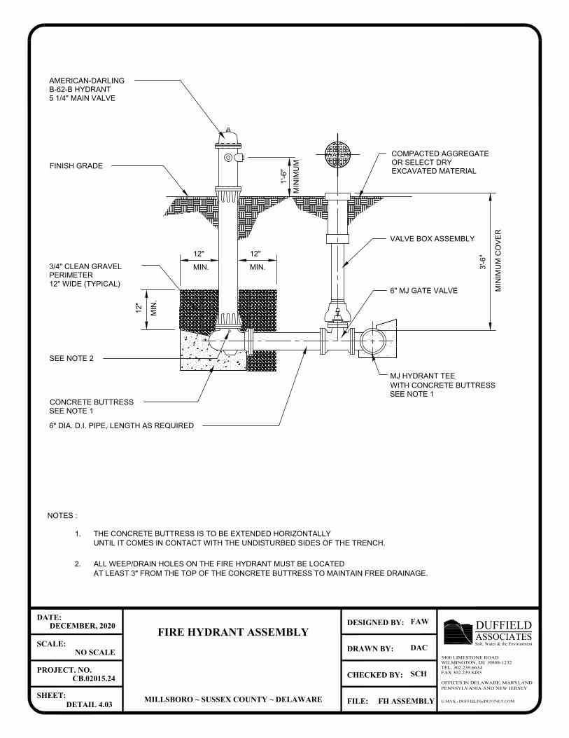
SEE NOTE 1
SEE NOTE 1
THE CONCRETE BUTTRESS IS TO BE EXTENDED HORIZONTALLY
6" DIA. D.I. PIPE, LENGTH AS REQUIRED
AT LEAST 3" FROM THE TOP OF THE CONCRETE BUTTRESS TO MAINTAIN FREE DRAINAGE.
UNTIL IT COMES IN CONTACT WITH THE UNDISTURBED SIDES OF THE TRENCH.
1.
NOTES :
MIN
IM
UM
SEE NOTE 2
CONCRETE BUTTRESS
MIN
.
12
"
PERIMETER
3/4" CLEAN GRAVEL
12" WIDE (TYPICAL)1
'-6
"
FINISH GRADE
WATER
OR SELECT DRY
MIN
IM
UM
C
OV
ER
WITH CONCRETE BUTTRESS
MJ HYDRANT TEE
6" MJ GATE VALVE
3'-6
"
EXCAVATED MATERIAL
VALVE BOX ASSEMBLY
COMPACTED AGGREGATE
ALL WEEP/DRAIN HOLES ON THE FIRE HYDRANT MUST BE LOCATED 2.
12"
MIN.
12"
MIN.
5 1/4" MAIN VALVE
AMERICAN-DARLING
B-62-B HYDRANT
E-MAIL: [email protected]
OFFICES IN DELAWARE, MARYLANDPENNSYLVANIA AND NEW JERSEY
CHECKED BY:
DRAWN BY:
FILE:
DESIGNED BY:
SHEET:
PROJECT. NO.
SCALE:
DATE:
ASSOCIATESDUFFIELDSoil, Water & the Environment
5400 LIMESTONE ROADWILMINGTON, DE 19808-1232TEL. 302.239.6634FAX 302.239.8485
FIRE HYDRANT ASSEMBLY
MILLSBORO ~ SUSSEX COUNTY ~ DELAWARE
DECEMBER, 2020
NO SCALE
CB.02015.24
DETAIL 4.03
FAW
DAC
SCH
FH ASSEMBLY
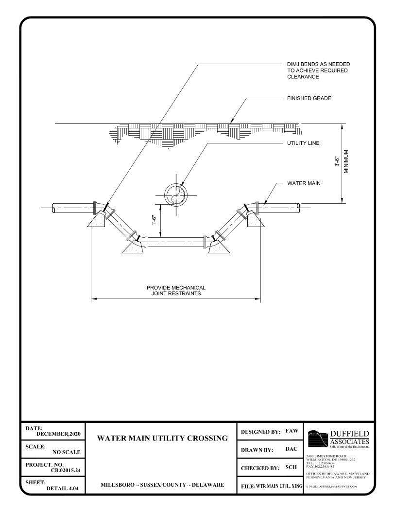
WATER MAIN
JOINT RESTRAINTS
FINISHED GRADE
UTILITY LINE
MIN
IM
UM
3'-6
"
1'-6
"
E-MAIL: [email protected]
OFFICES IN DELAWARE, MARYLANDPENNSYLVANIA AND NEW JERSEY
CHECKED BY:
DRAWN BY:
FILE:
DESIGNED BY:
SHEET:
PROJECT. NO.
SCALE:
DATE:
ASSOCIATESDUFFIELDSoil, Water & the Environment
5400 LIMESTONE ROADWILMINGTON, DE 19808-1232TEL. 302.239.6634FAX 302.239.8485
WATER MAIN UTILITY CROSSING
MILLSBORO ~ SUSSEX COUNTY ~ DELAWARE
DECEMBER,2020
NO SCALE
CB.02015.24
DETAIL 4.04
FAW
DAC
SCH
WTR MAIN UTIL. XING
DIMJ BENDS AS NEEDED
TO ACHIEVE REQUIRED
CLEARANCE
PROVIDE MECHANICAL
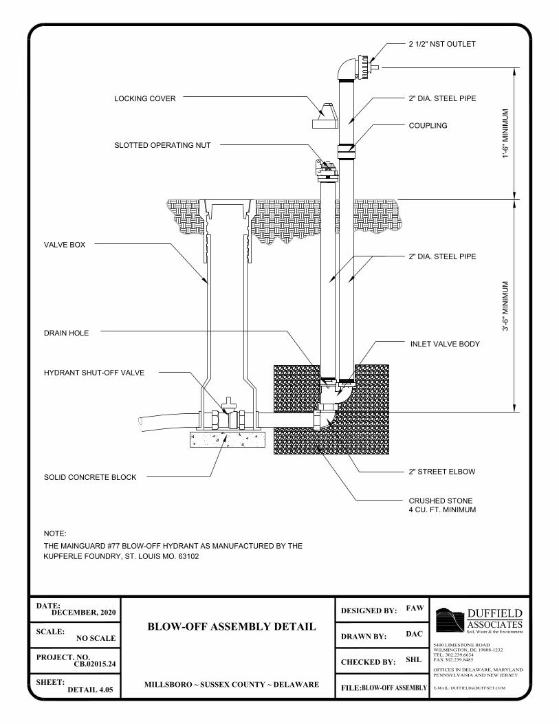
E-MAIL: [email protected]
OFFICES IN DELAWARE, MARYLANDPENNSYLVANIA AND NEW JERSEY
CHECKED BY:
DRAWN BY:
FILE:
DESIGNED BY:
SHEET:
PROJECT. NO.
SCALE:
DATE:
ASSOCIATESDUFFIELDSoil, Water & the Environment
5400 LIMESTONE ROADWILMINGTON, DE 19808-1232TEL. 302.239.6634FAX 302.239.8485
BLOW-OFF ASSEMBLY DETAIL
MILLSBORO ~ SUSSEX COUNTY ~ DELAWARE
DECEMBER, 2020
NO SCALE
CB.02015.24
DETAIL 4.05
FAW
DAC
SHL
BLOW-OFF ASSEMBLY
COUPLING
2 1/2" NST OUTLET
2" DIA. STEEL PIPELOCKING COVER
SLOTTED OPERATING NUT
VALVE BOX
HYDRANT SHUT-OFF VALVE
SOLID CONCRETE BLOCK
INLET VALVE BODY
DRAIN HOLE
2" DIA. STEEL PIPE
2" STREET ELBOW
CRUSHED STONE
THE MAINGUARD #77 BLOW-OFF HYDRANT AS MANUFACTURED BY THE
KUPFERLE FOUNDRY, ST. LOUIS MO. 63102
NOTE:
4 CU. FT. MINIMUM
3'-6
" M
IN
IM
UM
1'-6
" M
IN
IM
UM
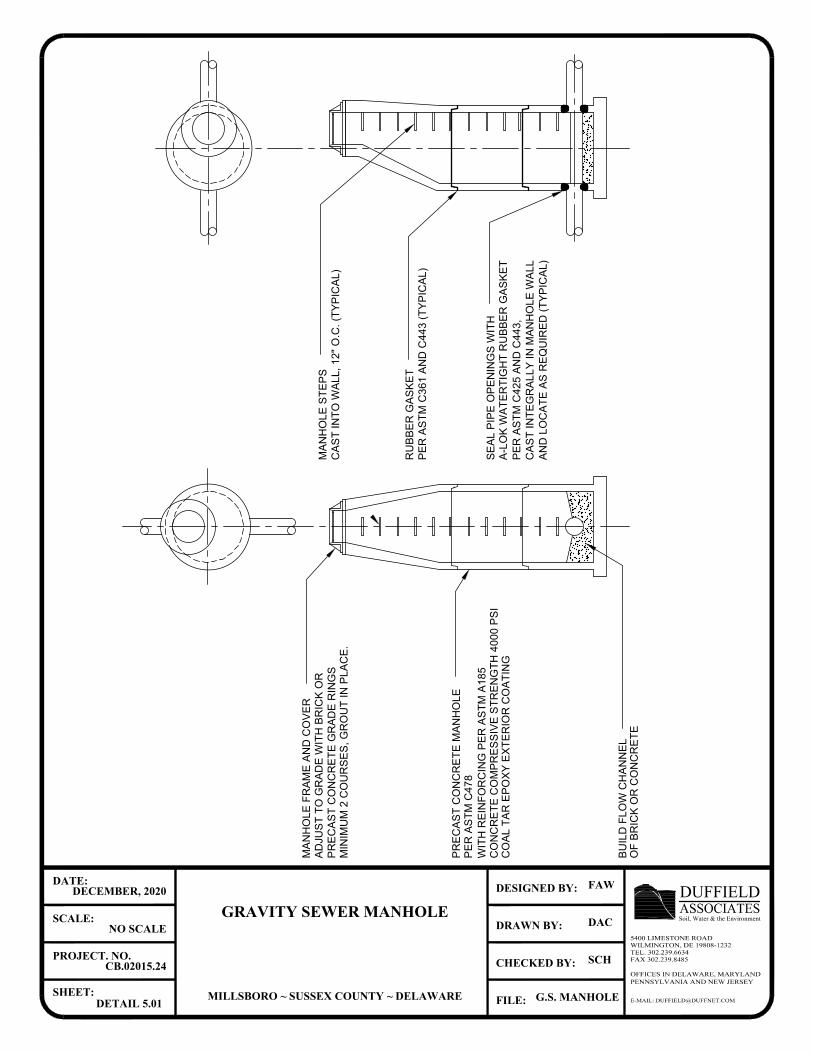
MA
NH
OL
E F
RA
ME
A
ND
C
OV
ER
AD
JU
ST
T
O G
RA
DE
W
IT
H B
RIC
K O
R
PR
EC
AS
T C
ON
CR
ET
E G
RA
DE
R
IN
GS
MIN
IM
UM
2
C
OU
RS
ES
, G
RO
UT
IN
P
LA
CE
.
CO
AL
T
AR
E
PO
XY
E
XT
ER
IO
R C
OA
TIN
G
CO
NC
RE
TE
C
OM
PR
ES
SIV
E S
TR
EN
GT
H 4
00
0 P
SI
WIT
H R
EIN
FO
RC
IN
G P
ER
A
ST
M A
18
5
PR
EC
AS
T C
ON
CR
ET
E M
AN
HO
LE
BU
IL
D F
LO
W C
HA
NN
EL
OF
B
RIC
K O
R C
ON
CR
ET
E
SE
AL
P
IP
E O
PE
NIN
GS
W
IT
H
A-L
OK
W
AT
ER
TIG
HT
R
UB
BE
R G
AS
KE
T
PE
R A
ST
M C
42
5 A
ND
C
44
3,
CA
ST
IN
TE
GR
AL
LY
IN
M
AN
HO
LE
W
AL
L
AN
D L
OC
AT
E A
S R
EQ
UIR
ED
(T
YP
IC
AL
)
PE
R A
ST
M C
36
1 A
ND
C
44
3 (T
YP
IC
AL
)
RU
BB
ER
G
AS
KE
T
MA
NH
OL
E S
TE
PS
CA
ST
IN
TO
W
AL
L, 1
2" O
.C
. (T
YP
IC
AL
)
E-MAIL: [email protected]
OFFICES IN DELAWARE, MARYLANDPENNSYLVANIA AND NEW JERSEY
CHECKED BY:
DRAWN BY:
FILE:
DESIGNED BY:
SHEET:
PROJECT. NO.
SCALE:
DATE:
ASSOCIATESDUFFIELDSoil, Water & the Environment
5400 LIMESTONE ROADWILMINGTON, DE 19808-1232TEL. 302.239.6634FAX 302.239.8485
GRAVITY SEWER MANHOLE
MILLSBORO ~ SUSSEX COUNTY ~ DELAWARE
DECEMBER, 2020
NO SCALE
CB.02015.24
DETAIL 5.01
FAW
DAC
SCH
G.S. MANHOLE
PE
R A
ST
M C
47
8
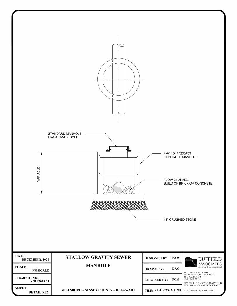
BUILD OF BRICK OR CONCRETE
FLOW CHANNEL
FRAME AND COVER
STANDARD MANHOLE
VA
RIA
BL
E
12" CRUSHED STONE
4'-0" I.D. PRECAST
CONCRETE MANHOLE
E-MAIL: [email protected]
OFFICES IN DELAWARE, MARYLANDPENNSYLVANIA AND NEW JERSEY
CHECKED BY:
DRAWN BY:
FILE:
DESIGNED BY:
SHEET:
PROJECT. NO.
SCALE:
DATE:
ASSOCIATESDUFFIELDSoil, Water & the Environment
5400 LIMESTONE ROADWILMINGTON, DE 19808-1232TEL. 302.239.6634FAX 302.239.8485
SHALLOW GRAVITY SEWER
MANHOLE
MILLSBORO ~ SUSSEX COUNTY ~ DELAWARE
DECEMBER, 2020
NO SCALE
CB.02015.24
DETAIL 5.02
FAW
DAC
SCH
SHALLOW GRAV. MH
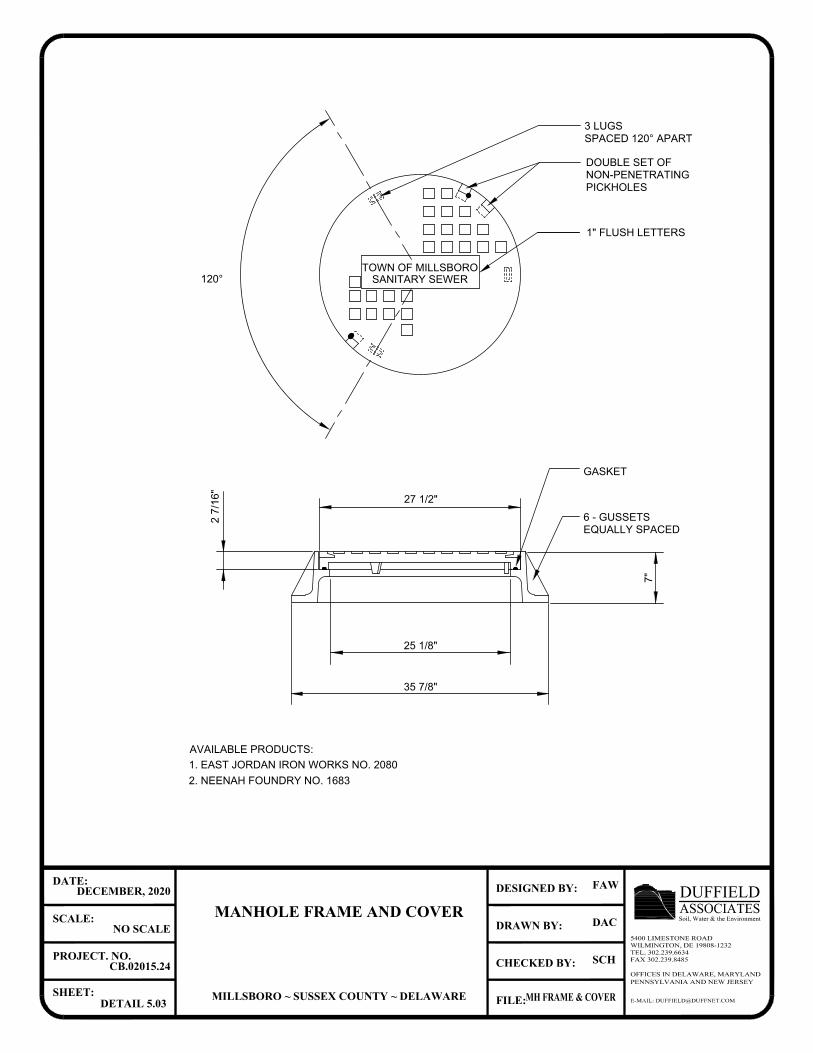
1" FLUSH LETTERS
7"
6 - GUSSETS
EQUALLY SPACED
GASKET
35 7/8"
2 7
/1
6"
120°
27 1/2"
SANITARY SEWER
SPACED 120° APART
DOUBLE SET OF
NON-PENETRATING
3 LUGS
PICKHOLES
25 1/8"
TOWN OF MILLSBORO
AVAILABLE PRODUCTS:
1. EAST JORDAN IRON WORKS NO. 2080
2. NEENAH FOUNDRY NO. 1683
E-MAIL: [email protected]
OFFICES IN DELAWARE, MARYLANDPENNSYLVANIA AND NEW JERSEY
CHECKED BY:
DRAWN BY:
FILE:
DESIGNED BY:
SHEET:
PROJECT. NO.
SCALE:
DATE:
ASSOCIATESDUFFIELDSoil, Water & the Environment
5400 LIMESTONE ROADWILMINGTON, DE 19808-1232TEL. 302.239.6634FAX 302.239.8485
MANHOLE FRAME AND COVER
MILLSBORO ~ SUSSEX COUNTY ~ DELAWARE
DECEMBER, 2020
NO SCALE
CB.02015.24
DETAIL 5.03
FAW
DAC
SCH
MH FRAME & COVER
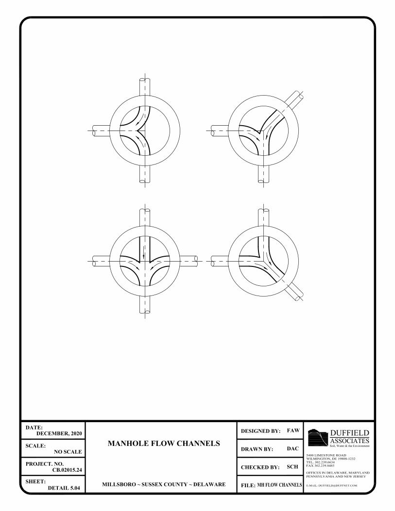
E-MAIL: [email protected]
OFFICES IN DELAWARE, MARYLANDPENNSYLVANIA AND NEW JERSEY
CHECKED BY:
DRAWN BY:
FILE:
DESIGNED BY:
SHEET:
PROJECT. NO.
SCALE:
DATE:
ASSOCIATESDUFFIELDSoil, Water & the Environment
5400 LIMESTONE ROADWILMINGTON, DE 19808-1232TEL. 302.239.6634FAX 302.239.8485
MANHOLE FLOW CHANNELS
MILLSBORO ~ SUSSEX COUNTY ~ DELAWARE
DECEMBER, 2020
NO SCALE
CB.02015.24
DETAIL 5.04
FAW
DAC
SCH
MH FLOW CHANNELS
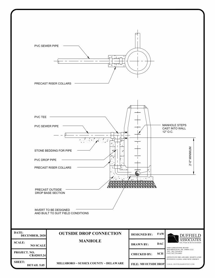
PVC TEE
INVERT TO BE DESIGNED
AND BUILT TO SUIT FIELD CONDITIONS
PVC SEWER PIPE
STONE BEDDING FOR PIPE
PVC DROP PIPE
PRECAST RISER COLLARS
PRECAST OUTSIDE
DROP BASE SECTION
2'-0
" M
IN
IM
UM
MANHOLE STEPS
CAST INTO WALL
12" O.C.
PVC SEWER PIPE
PRECAST RISER COLLARS
E-MAIL: [email protected]
OFFICES IN DELAWARE, MARYLANDPENNSYLVANIA AND NEW JERSEY
CHECKED BY:
DRAWN BY:
FILE:
DESIGNED BY:
SHEET:
PROJECT. NO.
SCALE:
DATE:
ASSOCIATESDUFFIELDSoil, Water & the Environment
5400 LIMESTONE ROADWILMINGTON, DE 19808-1232TEL. 302.239.6634FAX 302.239.8485
OUTSIDE DROP CONNECTION
MANHOLE
MILLSBORO ~ SUSSEX COUNTY ~ DELAWARE
DECEMBER, 2020
NO SCALE
CB.02015.24
DETAIL 5.05
FAW
DAC
SCH
MH OUTSIDE DROP
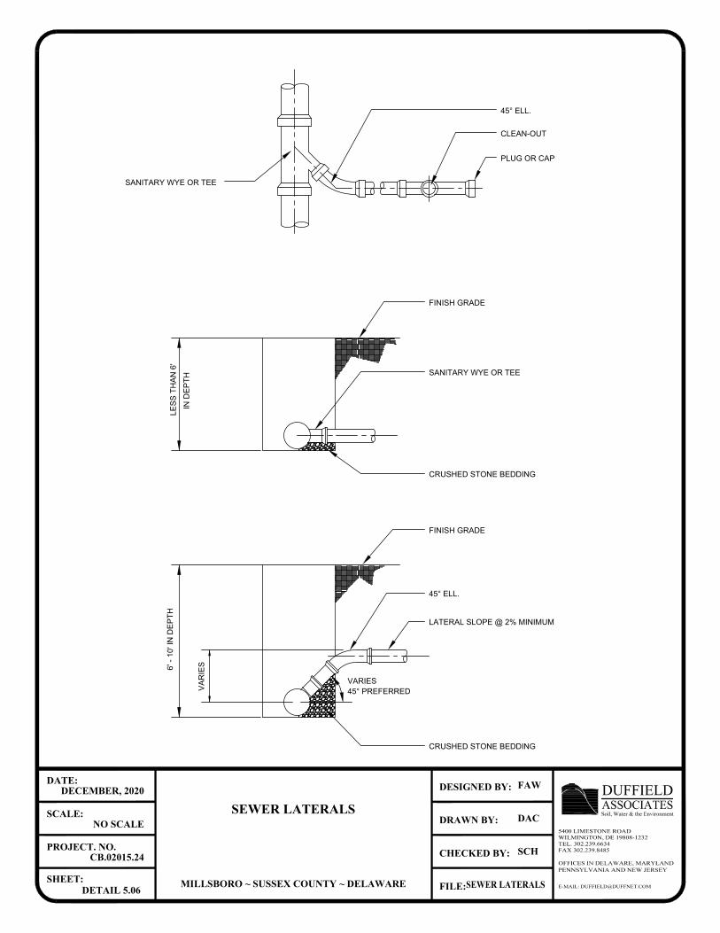
45° PREFERRED
VARIES
VA
RIE
S
6' - 10' IN
D
EP
TH
45° ELL.
CLEAN-OUT
PLUG OR CAP
SANITARY WYE OR TEE
FINISH GRADE
SANITARY WYE OR TEE
LATERAL SLOPE @ 2% MINIMUM
FINISH GRADE
45° ELL.
LE
SS
T
HA
N 6'
IN
D
EP
TH
CRUSHED STONE BEDDING
CRUSHED STONE BEDDING
E-MAIL: [email protected]
OFFICES IN DELAWARE, MARYLANDPENNSYLVANIA AND NEW JERSEY
CHECKED BY:
DRAWN BY:
FILE:
DESIGNED BY:
SHEET:
PROJECT. NO.
SCALE:
DATE:
ASSOCIATESDUFFIELDSoil, Water & the Environment
5400 LIMESTONE ROADWILMINGTON, DE 19808-1232TEL. 302.239.6634FAX 302.239.8485
SEWER LATERALS
MILLSBORO ~ SUSSEX COUNTY ~ DELAWARE
DECEMBER, 2020
NO SCALE
CB.02015.24
DETAIL 5.06
FAW
DAC
SCH
SEWER LATERALS
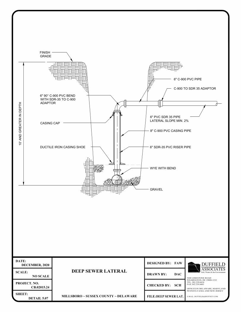
GRAVEL
CASING CAP
8" C-900 PVC CASING PIPE
DUCTILE IRON CASING SHOE 6" SDR-35 PVC RISER PIPE
6" C-900 PVC PIPE
6" PVC SDR 35 PIPE
C-900 TO SDR 35 ADAPTOR
LATERAL SLOPE MIN. 2%
WYE WITH BEND
10
' A
ND
G
RE
AT
ER
IN
D
EP
TH
6" 90° C-900 PVC BEND
WITH SDR-35 TO C-900
ADAPTOR
GRADE
FINISH
E-MAIL: [email protected]
OFFICES IN DELAWARE, MARYLANDPENNSYLVANIA AND NEW JERSEY
CHECKED BY:
DRAWN BY:
FILE:
DESIGNED BY:
SHEET:
PROJECT. NO.
SCALE:
DATE:
ASSOCIATESDUFFIELDSoil, Water & the Environment
5400 LIMESTONE ROADWILMINGTON, DE 19808-1232TEL. 302.239.6634FAX 302.239.8485
DEEP SEWER LATERAL
MILLSBORO ~ SUSSEX COUNTY ~ DELAWARE
DECEMBER, 2020
NO SCALE
CB.02015.24
DETAIL 5.07
FAW
DAC
SCH
DEEP SEWER LAT.
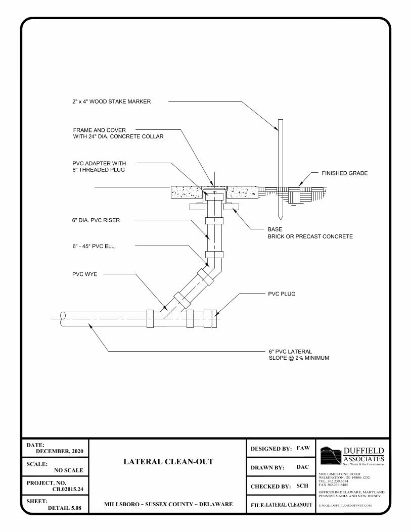
FINISHED GRADE
2" x 4" WOOD STAKE MARKER
BASE
PVC PLUG
FRAME AND COVER
6" THREADED PLUG
PVC ADAPTER WITH
6" DIA. PVC RISER
PVC WYE
6" - 45° PVC ELL.
WITH 24" DIA. CONCRETE COLLAR
6" PVC LATERAL
SLOPE @ 2% MINIMUM
BRICK OR PRECAST CONCRETE
E-MAIL: [email protected]
OFFICES IN DELAWARE, MARYLANDPENNSYLVANIA AND NEW JERSEY
CHECKED BY:
DRAWN BY:
FILE:
DESIGNED BY:
SHEET:
PROJECT. NO.
SCALE:
DATE:
ASSOCIATESDUFFIELDSoil, Water & the Environment
5400 LIMESTONE ROADWILMINGTON, DE 19808-1232TEL. 302.239.6634FAX 302.239.8485
LATERAL CLEAN-OUT
MILLSBORO ~ SUSSEX COUNTY ~ DELAWARE
DECEMBER, 2020
NO SCALE
CB.02015.24
DETAIL 5.08
FAW
DAC
SCH
LATERAL CLEANOUT
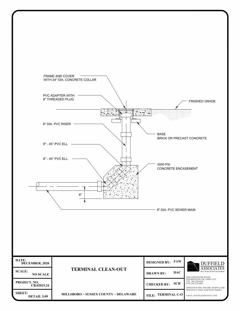
BRICK OR PRECAST CONCRETE
8" DIA. PVC SEWER MAIN
WITH 24" DIA. CONCRETE COLLAR
8" - 45° PVC ELL.
8" DIA. PVC RISER
PVC ADAPTER WITH
8" THREADED PLUG
FRAME AND COVER
BASE
FINISHED GRADE
8" - 45° PVC ELL.
3000 PSI
CONCRETE ENCASEMENT
8"
E-MAIL: [email protected]
OFFICES IN DELAWARE, MARYLANDPENNSYLVANIA AND NEW JERSEY
CHECKED BY:
DRAWN BY:
FILE:
DESIGNED BY:
SHEET:
PROJECT. NO.
SCALE:
DATE:
ASSOCIATESDUFFIELDSoil, Water & the Environment
5400 LIMESTONE ROADWILMINGTON, DE 19808-1232TEL. 302.239.6634FAX 302.239.8485
TERMINAL CLEAN-OUT
MILLSBORO ~ SUSSEX COUNTY ~ DELAWARE
DECEMBER, 2020
NO SCALE
CB.02015.24
DETAIL 5.09
FAW
DAC
SCH
TERMINAL C-O
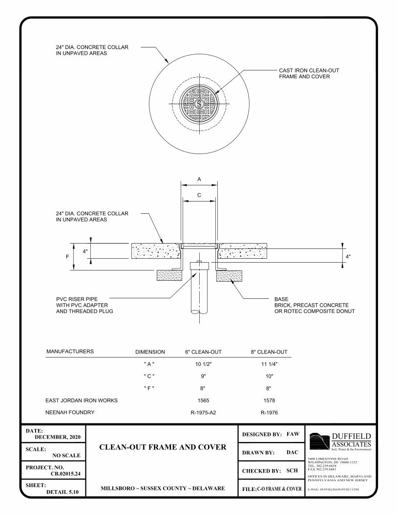
CAST IRON CLEAN-OUT
FRAME AND COVER
24" DIA. CONCRETE COLLAR
IN UNPAVED AREAS
AND THREADED PLUG
WITH PVC ADAPTER
PVC RISER PIPE
MANUFACTURERS
EAST JORDAN IRON WORKS
NEENAH FOUNDRY
A
C
F
4"
4"
BASE
BRICK, PRECAST CONCRETE
24" DIA. CONCRETE COLLAR
IN UNPAVED AREAS
6" CLEAN-OUT
10 1/2"
9"
8"
1565
R-1975-A2 R-1976
1578
8"
10"
11 1/4"
8" CLEAN-OUT
" A "
" C "
" F "
DIMENSION
E-MAIL: [email protected]
OFFICES IN DELAWARE, MARYLANDPENNSYLVANIA AND NEW JERSEY
CHECKED BY:
DRAWN BY:
FILE:
DESIGNED BY:
SHEET:
PROJECT. NO.
SCALE:
DATE:
ASSOCIATESDUFFIELDSoil, Water & the Environment
5400 LIMESTONE ROADWILMINGTON, DE 19808-1232TEL. 302.239.6634FAX 302.239.8485
CLEAN-OUT FRAME AND COVER
MILLSBORO ~ SUSSEX COUNTY ~ DELAWARE
DECEMBER, 2020
NO SCALE
CB.02015.24
DETAIL 5.10
FAW
DAC
SCH
C-O FRAME & COVER
OR ROTEC COMPOSITE DONUT
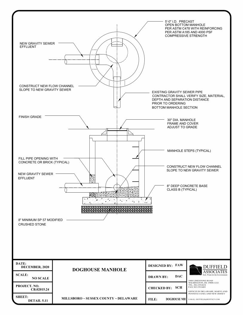
E-MAIL: [email protected]
OFFICES IN DELAWARE, MARYLANDPENNSYLVANIA AND NEW JERSEY
CHECKED BY:
DRAWN BY:
FILE:
DESIGNED BY:
SHEET:
PROJECT. NO.
SCALE:
DATE:
ASSOCIATESDUFFIELDSoil, Water & the Environment
5400 LIMESTONE ROADWILMINGTON, DE 19808-1232TEL. 302.239.6634FAX 302.239.8485
DOGHOUSE MANHOLE
MILLSBORO ~ SUSSEX COUNTY ~ DELAWARE
DECEMBER, 2020
NO SCALE
CB.02015.24
DETAIL 5.11
FAW
DAC
SCH
DOGHOUSE MH
SLOPE TO NEW GRAVITY SEWER
CONSTRUCT NEW FLOW CHANNEL
NEW GRAVITY SEWER
MANHOLE STEPS (TYPICAL)
FINISH GRADE
FILL PIPE OPENING WITH
CLASS B (TYPICAL)
30" DIA. MANHOLE
ADJUST TO GRADE
5'-0" I.D. PRECAST
PER ASTM C478 WITH REINFORCING
COMPRESSIVE STRENGTH
PER ASTM A185 AND 4000 PSF
OPEN BOTTOM MANHOLE
FRAME AND COVER
CONCRETE OR BRICK (TYPICAL)
8" DEEP CONCRETE BASE
8" MINIMUM SP 57 MODIFIED
NEW GRAVITY SEWER
EFFLUENT
EXISTING GRAVITY SEWER PIPE
DEPTH AND SEPARATION DISTANCE
CONTRACTOR SHALL VERIFY SIZE, MATERIAL,
PRIOR TO ORDERING
EFFLUENT
SLOPE TO NEW GRAVITY SEWER
CONSTRUCT NEW FLOW CHANNEL
BOTTOM MANHOLE SECTION
CRUSHED STONE
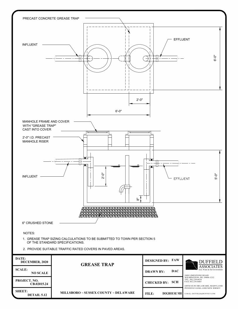
E-MAIL: [email protected]
OFFICES IN DELAWARE, MARYLANDPENNSYLVANIA AND NEW JERSEY
CHECKED BY:
DRAWN BY:
FILE:
DESIGNED BY:
SHEET:
PROJECT. NO.
SCALE:
DATE:
ASSOCIATESDUFFIELDSoil, Water & the Environment
5400 LIMESTONE ROADWILMINGTON, DE 19808-1232TEL. 302.239.6634FAX 302.239.8485
GREASE TRAP
MILLSBORO ~ SUSSEX COUNTY ~ DELAWARE
DECEMBER, 2020
NO SCALE
CB.02015.24
DETAIL 5.12
FAW
DAC
SCH
DOGHOUSE MH
2'-0
"
8"
6'-0"
6'-0
"
5'-0
"
2'-0"
PRECAST CONCRETE GREASE TRAP
EFFLUENT
INFLUENT
2'-0" I.D. PRECAST
MANHOLE RISER
6" CRUSHED STONE
MANHOLE FRAME AND COVER
WITH "GREASE TRAP"
CAST INTO COVER
NOTES:
1. GREASE TRAP SIZING CALCULATIONS TO BE SUBMITTED TO TOWN PER SECTION 5
2. PROVIDE SUITABLE TRAFFIC RATED COVERS IN PAVED AREAS.
INFLUENT
OF THE STANDARD SPECIFICATIONS.
AutoCAD SHX Text
EFFLUENT
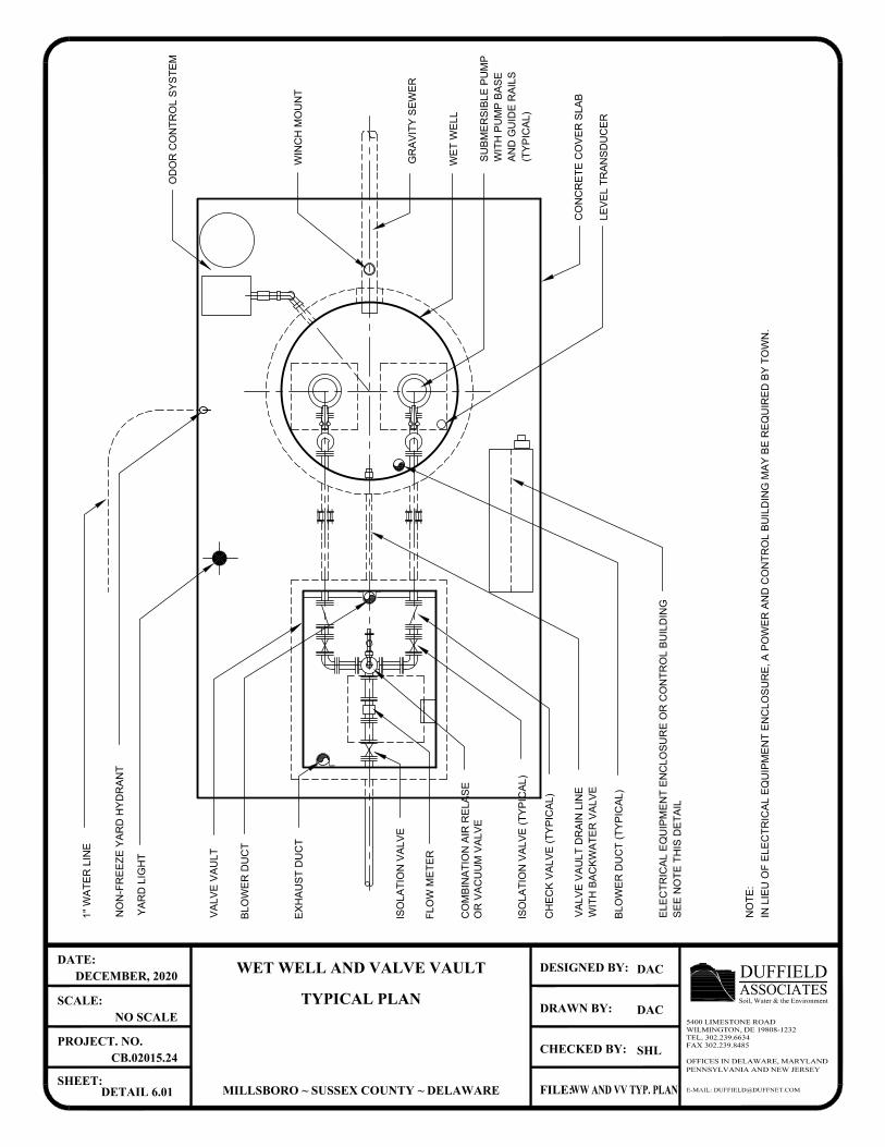
CO
MB
IN
AT
IO
N A
IR
R
ELA
SE
IS
OLA
TIO
N V
ALV
E (T
YP
IC
AL)
CH
EC
K V
ALV
E (T
YP
IC
AL)
NO
N-F
RE
EZ
E Y
AR
D H
YD
RA
NT
1" W
AT
ER
LIN
E
WE
T W
ELL
WIN
CH
M
OU
NT
VA
LV
E V
AU
LT
SU
BM
ER
SIB
LE
P
UM
P
GR
AV
IT
Y S
EW
ER
BLO
WE
R D
UC
T (T
YP
IC
AL)
VA
LV
E V
AU
LT
D
RA
IN
LIN
E
WIT
H B
AC
KW
AT
ER
V
ALV
E
YA
RD
LIG
HT
ELE
CT
RIC
AL E
QU
IP
ME
NT
E
NC
LO
SU
RE
O
R C
ON
TR
OL B
UILD
IN
G
WIT
H P
UM
P B
AS
E
AN
D G
UID
E R
AILS
(T
YP
IC
AL)
E-MAIL: [email protected]
OFFICES IN DELAWARE, MARYLANDPENNSYLVANIA AND NEW JERSEY
CHECKED BY:
DRAWN BY:
FILE:
DESIGNED BY:
SHEET:
PROJECT. NO.
SCALE:
DATE:
ASSOCIATESDUFFIELDSoil, Water & the Environment
5400 LIMESTONE ROADWILMINGTON, DE 19808-1232TEL. 302.239.6634FAX 302.239.8485
WET WELL AND VALVE VAULT
TYPICAL PLAN
MILLSBORO ~ SUSSEX COUNTY ~ DELAWARE
DECEMBER, 2020
NO SCALE
CB.02015.24
DETAIL 6.01
DAC
DAC
SHL
WW AND VV TYP. PLAN
CO
NC
RE
TE
C
OV
ER
S
LA
B
LE
VE
L T
RA
NS
DU
CE
R
OD
OR
C
ON
TR
OL S
YS
TE
M
BLO
WE
R D
UC
T
EX
HA
US
T D
UC
T
IS
OLA
TIO
N V
ALV
E
FLO
W M
ET
ER
OR
V
AC
UU
M V
ALV
E
SE
E N
OT
E T
HIS
D
ET
AIL
IN
LIE
U O
F E
LE
CT
RIC
AL E
QU
IP
ME
NT
E
NC
LO
SU
RE
, A
P
OW
ER
A
ND
C
ON
TR
OL B
UILD
IN
G M
AY
B
E R
EQ
UIR
ED
B
Y T
OW
N.
NO
TE
:
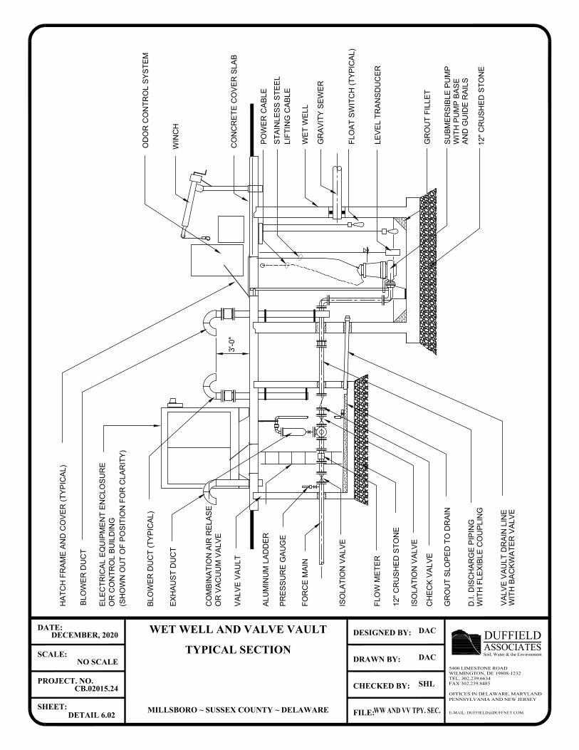
GR
AV
IT
Y S
EW
ER
GR
OU
T F
IL
LE
T
SU
BM
ER
SIB
LE
P
UM
P
FL
OA
T S
WIT
CH
(T
YP
IC
AL
)
WIT
H B
AC
KW
AT
ER
V
AL
VE
VA
LV
E V
AU
LT
D
RA
IN
L
IN
E
D.I. D
IS
CH
AR
GE
P
IP
IN
G
GR
OU
T S
LO
PE
D T
O D
RA
IN
12
" C
RU
SH
ED
S
TO
NE
12
" C
RU
SH
ED
S
TO
NE
VA
LV
E V
AU
LT
IS
OL
AT
IO
N V
AL
VE
CH
EC
K V
AL
VE
PR
ES
SU
RE
G
AU
GE
FO
RC
E M
AIN
CO
MB
IN
AT
IO
N A
IR
R
EL
AS
E
AL
UM
IN
UM
L
AD
DE
R
WIT
H F
LE
XIB
LE
C
OU
PL
IN
G
BL
OW
ER
D
UC
T (T
YP
IC
AL
)
EL
EC
TR
IC
AL
E
QU
IP
ME
NT
E
NC
LO
SU
RE
WIN
CH
BL
OW
ER
D
UC
T
HA
TC
H F
RA
ME
A
ND
C
OV
ER
(T
YP
IC
AL
)
CO
NC
RE
TE
C
OV
ER
S
LA
B
WIT
H P
UM
P B
AS
E
AN
D G
UID
E R
AIL
S
WE
T W
EL
L
PO
WE
R C
AB
LE
ST
AIN
LE
SS
S
TE
EL
LIF
TIN
G C
AB
LE
3'-0
"
E-MAIL: [email protected]
OFFICES IN DELAWARE, MARYLANDPENNSYLVANIA AND NEW JERSEY
CHECKED BY:
DRAWN BY:
FILE:
DESIGNED BY:
SHEET:
PROJECT. NO.
SCALE:
DATE:
ASSOCIATESDUFFIELDSoil, Water & the Environment
5400 LIMESTONE ROADWILMINGTON, DE 19808-1232TEL. 302.239.6634FAX 302.239.8485
WET WELL AND VALVE VAULT
TYPICAL SECTION
MILLSBORO ~ SUSSEX COUNTY ~ DELAWARE
DECEMBER, 2020
NO SCALE
CB.02015.24
DETAIL 6.02
DAC
DAC
SHL
WW AND VV TPY. SEC.
LE
VE
L T
RA
NS
DU
CE
R
OD
OR
C
ON
TR
OL
S
YS
TE
M
FL
OW
M
ET
ER
IS
OL
AT
IO
N V
AL
VE
OR
C
ON
TR
OL
B
UIL
DIN
G
EX
HA
US
T D
UC
T
OR
V
AC
UU
M V
AL
VE
(S
HO
WN
O
UT
O
F P
OS
IT
IO
N F
OR
C
LA
RIT
Y)
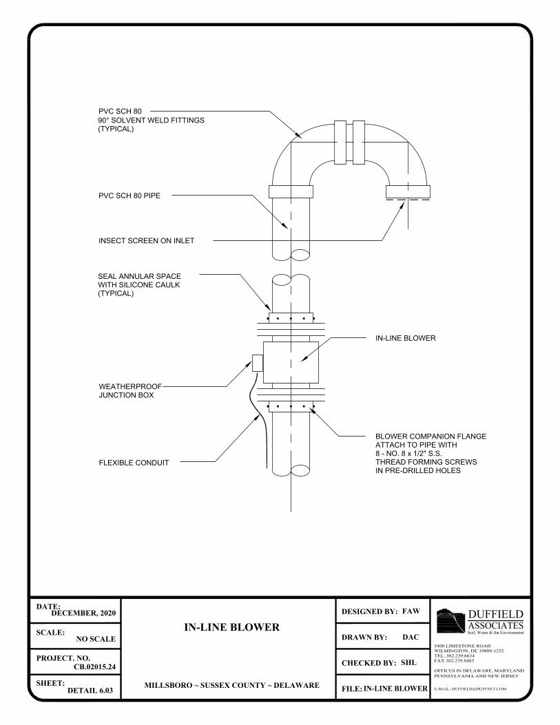
(TYPICAL)
90° SOLVENT WELD FITTINGS
PVC SCH 80
INSECT SCREEN ON INLET
IN PRE-DRILLED HOLES
THREAD FORMING SCREWS
8 - NO. 8 x 1/2" S.S.
ATTACH TO PIPE WITH
BLOWER COMPANION FLANGE
IN-LINE BLOWER
PVC SCH 80 PIPE
(TYPICAL)
WITH SILICONE CAULK
SEAL ANNULAR SPACE
FLEXIBLE CONDUIT
JUNCTION BOX
WEATHERPROOF
E-MAIL: [email protected]
OFFICES IN DELAWARE, MARYLANDPENNSYLVANIA AND NEW JERSEY
CHECKED BY:
DRAWN BY:
FILE:
DESIGNED BY:
SHEET:
PROJECT. NO.
SCALE:
DATE:
ASSOCIATESDUFFIELDSoil, Water & the Environment
5400 LIMESTONE ROADWILMINGTON, DE 19808-1232TEL. 302.239.6634FAX 302.239.8485
IN-LINE BLOWER
MILLSBORO ~ SUSSEX COUNTY ~ DELAWARE
DECEMBER, 2020
NO SCALE
CB.02015.24
DETAIL 6.03
FAW
DAC
SHL
IN-LINE BLOWER
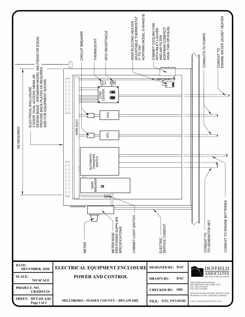
E-MAIL: [email protected]
OFFICES IN DELAWARE, MARYLANDPENNSYLVANIA AND NEW JERSEY
CHECKED BY:
DRAWN BY:
FILE:
DESIGNED BY:
SHEET:
PROJECT. NO.
SCALE:
DATE:
ASSOCIATESDUFFIELDSoil, Water & the Environment
5400 LIMESTONE ROADWILMINGTON, DE 19808-1232TEL. 302.239.6634FAX 302.239.8485
ELECTRICAL EQUIPMENT ENCLOSURE
POWER AND CONTROL
MILLSBORO ~ SUSSEX COUNTY ~ DELAWARE
DECEMBER, 2020
NO SCALE
CB.02015.24
DETAIL 6.04Page 1 of 2
DAC
DAC
SHL
ELEC. ENCLOSURE
PR
OV
ID
E B
AC
K P
LA
TE
S A
S R
EQ
UIR
ED
DE
SIG
N B
AS
IS
: W
IE
GM
AN
N M
OD
EL
W
A-F
SD
AD
O
R E
QU
AL
2 D
OO
R, D
UA
L A
CC
ES
S, N
EM
A 3
R
EL
EC
TR
IC
AL
E
NC
LO
SU
RE
SP
EC
IF
IC
AT
IO
NS
PE
R P
OW
ER
S
UP
PL
IE
R
ME
TE
R B
AS
E
ME
TE
R
WIR
E D
UC
T
SW
IT
CH
TR
AN
SF
ER
AU
TO
MA
TIC
BR
EA
KE
R
MA
IN
CA
BIN
ET
L
IG
HT
S
WIT
CH
LO
AD
CE
NT
ER
GF
CI R
EC
EP
TA
CL
E
TH
ER
MO
ST
AT
TO
G
EN
ER
AT
OR
S
ET
CA
BIN
ET
C
OO
LIN
G F
AN
AN
D A
IR
F
IL
TE
R
HO
FF
MA
N C
OM
PA
CT
HO
FF
MA
N M
OD
EL
D
-A
H4
00
1B
AD
JU
ST
AB
LE
T
HE
RM
OS
TA
T
40
0W
E
LE
CT
RIC
H
EA
TE
R
EN
GIN
E W
AT
ER
JA
CK
ET
H
EA
TE
R
SE
RV
IC
E C
ON
DU
IT
SIZ
E F
OR
E
QU
IP
ME
NT
S
HO
WN
EL
EC
TR
IC
CO
ND
UIT
T
O
CO
ND
UIT
T
O E
NG
IN
E B
AT
TE
RIE
S
CO
ND
UIT
T
O
WIT
H IN
LE
T L
OU
VE
R
AS
R
EQ
UIR
ED
VF
DV
FD
CO
ND
UIT
S T
O P
UM
PS
CIR
CU
IT
B
RE
AK
ER
0° T
O 1
00
°
AX
IA
L F
AN
O
R E
QU
AL
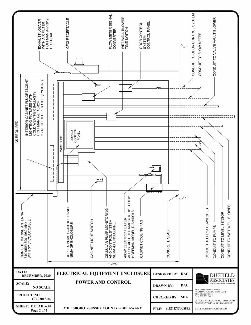
E-MAIL: [email protected]
OFFICES IN DELAWARE, MARYLANDPENNSYLVANIA AND NEW JERSEY
CHECKED BY:
DRAWN BY:
FILE:
DESIGNED BY:
SHEET:
PROJECT. NO.
SCALE:
DATE:
ASSOCIATESDUFFIELDSoil, Water & the Environment
5400 LIMESTONE ROADWILMINGTON, DE 19808-1232TEL. 302.239.6634FAX 302.239.8485
ELECTRICAL EQUIPMENT ENCLOSURE
POWER AND CONTROL
MILLSBORO ~ SUSSEX COUNTY ~ DELAWARE
DECEMBER, 2020
NO SCALE
CB.02015.24
DETAIL 6.04Page 2 of 2
DAC
DAC
SHL
ELEC. ENCLOSURE
40
0W
E
LE
CT
RIC
H
EA
TE
R
AD
JU
ST
AB
LE
T
HE
RM
OS
TA
T 0
° T
O 1
00
°
HO
FF
MA
N M
OD
EL
D
-A
H4
00
1B
CA
BIN
ET
L
IG
HT
S
WIT
CH
CO
NC
RE
TE
S
LA
B
WIR
E D
UC
T
PA
NE
L
CO
NT
RO
L
CA
BIN
ET
C
OO
LIN
G F
AN
CO
NV
ER
TE
R
CO
ND
UIT
T
O F
LO
W M
ET
ER
CO
ND
UIT
T
O P
UM
PS
CO
ND
UIT
T
O F
LO
AT
S
WIT
CH
ES
WIT
H A
IR
F
IL
TE
R
HO
FF
MA
N A
-V
K8
12
CO
ND
UIT
T
O L
EV
EL
S
EN
SO
R
2 - R
EQ
UIR
ED
P
ER
S
ID
E (T
YP
IC
AL
)
HO
FF
MA
N A
-L
F1
6M
24
CO
LD
W
EA
TH
ER
B
AL
LA
ST
S
LIG
HT
IN
G F
IX
TU
RE
S W
IT
H
IN
TE
RIO
R C
AB
IN
ET
F
LU
OR
ES
CE
NT
DU
PL
EX
P
UM
P C
ON
TR
OL
P
AN
EL
NE
MA
3
R E
NC
LO
SU
RE
GF
CI R
EC
EP
TA
CL
E
CO
ND
UIT
T
O V
AL
VE
V
AU
LT
B
LO
WE
R
CO
ND
UIT
T
O W
ET
W
EL
L B
LO
WE
R
TIM
E S
WIT
CH
DU
PLE
X
6'-8" ±
AS
R
EQ
UIR
ED
NE
MA
4
X E
NC
LO
SU
RE
AN
D C
ON
TR
OL
S
YS
TE
M
CE
LL
UL
AR
P
UM
P M
ON
IT
OR
IN
G
FL
OW
M
ET
ER
S
IG
NA
L
WE
T W
EL
L B
LO
WE
R
EX
HA
US
T L
OU
VE
R
OR
E
QU
AL
CO
ND
UIT
T
O O
DO
R C
ON
TR
OL
S
YS
TE
M
CO
NT
RO
L P
AN
EL
SY
ST
EM
OD
OR
C
ON
TR
OL
OM
NIS
IT
E M
AR
IN
E A
NT
EN
NA
81
0-9
50
/1
80
0-1
98
0 M
Hz
WIT
H 3
/1
6" C
OA
X C
AB
LE
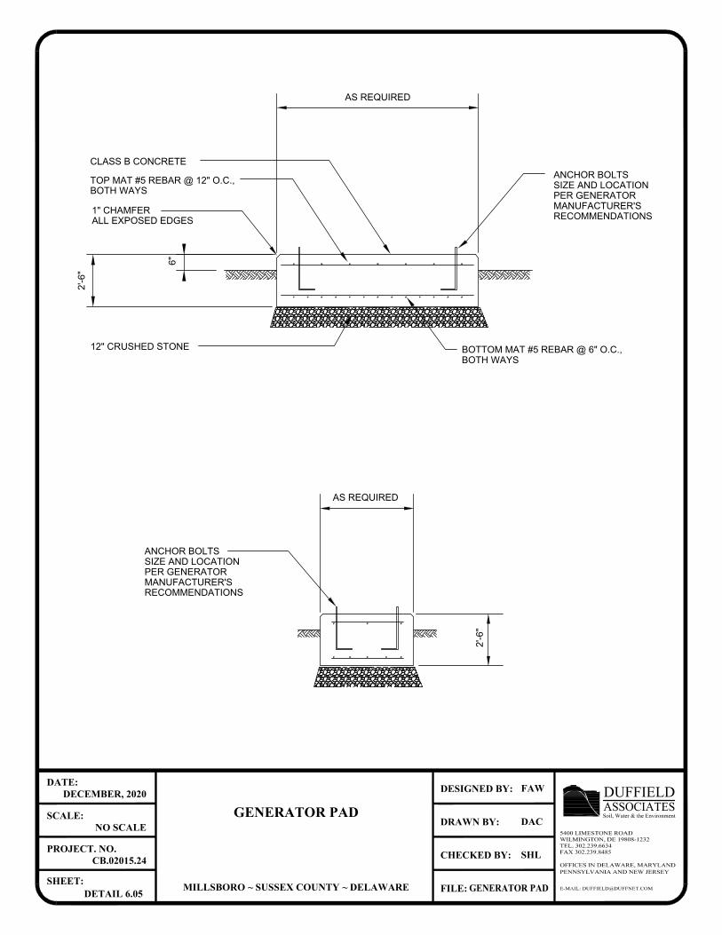
6"
2'-6
"
AS REQUIRED
2'-6
"
AS REQUIRED
BOTH WAYS
BOTTOM MAT #5 REBAR @ 6" O.C.,
RECOMMENDATIONS
MANUFACTURER'S
PER GENERATOR
SIZE AND LOCATION
ANCHOR BOLTS
ALL EXPOSED EDGES
1" CHAMFER
12" CRUSHED STONE
BOTH WAYS
TOP MAT #5 REBAR @ 12" O.C.,
CLASS B CONCRETE
ANCHOR BOLTS
SIZE AND LOCATION
PER GENERATOR
MANUFACTURER'S
RECOMMENDATIONS
E-MAIL: [email protected]
OFFICES IN DELAWARE, MARYLANDPENNSYLVANIA AND NEW JERSEY
CHECKED BY:
DRAWN BY:
FILE:
DESIGNED BY:
SHEET:
PROJECT. NO.
SCALE:
DATE:
ASSOCIATESDUFFIELDSoil, Water & the Environment
5400 LIMESTONE ROADWILMINGTON, DE 19808-1232TEL. 302.239.6634FAX 302.239.8485
GENERATOR PAD
MILLSBORO ~ SUSSEX COUNTY ~ DELAWARE
DECEMBER, 2020
NO SCALE
CB.02015.24
DETAIL 6.05
FAW
DAC
SHL
GENERATOR PAD
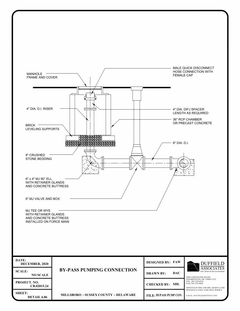
4" DIA. D.I. RISER
FEMALE CAP
HOSE CONNECTION WITH
MALE QUICK DISCONNECT
4" DIA. DIFJ SPACER
LENGTH AS REQUIRED
6" DIA. D.I.
36" RCP CHAMBER
OR PRECAST CONCRETE
MANHOLE
STONE BEDDING
LEVELING SUPPORTS
6" x 4" MJ 90° ELL.
WITH RETAINER GLANDS
AND CONCRETE BUTTRESS
BRICK
8" CRUSHED
6" MJ VALVE AND BOX
MJ TEE OR WYE
WITH RETAINER GLANDS
AND CONCRETE BUTTRESS
INSTALLED ON FORCE MAIN
FRAME AND COVER
E-MAIL: [email protected]
OFFICES IN DELAWARE, MARYLANDPENNSYLVANIA AND NEW JERSEY
CHECKED BY:
DRAWN BY:
FILE:
DESIGNED BY:
SHEET:
PROJECT. NO.
SCALE:
DATE:
ASSOCIATESDUFFIELDSoil, Water & the Environment
5400 LIMESTONE ROADWILMINGTON, DE 19808-1232TEL. 302.239.6634FAX 302.239.8485
BY-PASS PUMPING CONNECTION
MILLSBORO ~ SUSSEX COUNTY ~ DELAWARE
DECEMBER, 2020
NO SCALE
CB.02015.24
DETAIL 6.06
FAW
DAC
SHL
BYPASS PUMP CON.
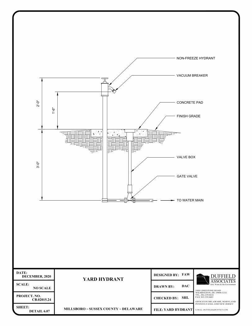
VALVE BOX
GATE VALVE
NON-FREEZE HYDRANT
CONCRETE PAD
FINISH GRADE
1'-6
"
2'-0
"3
'-0
"
VACUUM BREAKER
TO WATER MAIN
E-MAIL: [email protected]
OFFICES IN DELAWARE, MARYLANDPENNSYLVANIA AND NEW JERSEY
CHECKED BY:
DRAWN BY:
FILE:
DESIGNED BY:
SHEET:
PROJECT. NO.
SCALE:
DATE:
ASSOCIATESDUFFIELDSoil, Water & the Environment
5400 LIMESTONE ROADWILMINGTON, DE 19808-1232TEL. 302.239.6634FAX 302.239.8485
YARD HYDRANT
MILLSBORO ~ SUSSEX COUNTY ~ DELAWARE
DECEMBER, 2020
NO SCALE
CB.02015.24
DETAIL 6.07
FAW
DAC
SHL
YARD HYDRANT
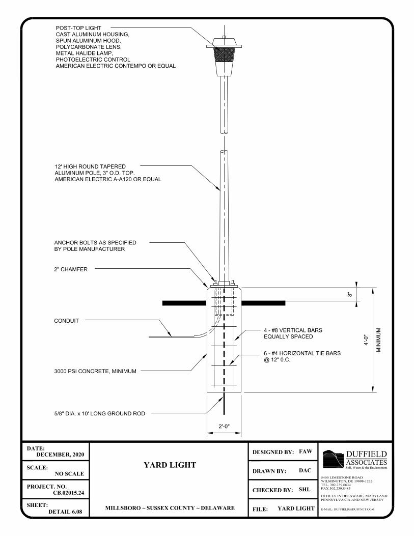
5/8" DIA. x 10' LONG GROUND ROD
CONDUIT
@ 12" 0.C.
6 - #4 HORIZONTAL TIE BARS
EQUALLY SPACED
4 - #8 VERTICAL BARS
3000 PSI CONCRETE, MINIMUM
2" CHAMFER
BY POLE MANUFACTURER
ANCHOR BOLTS AS SPECIFIED
8"
4'-0
"
12' HIGH ROUND TAPERED
ALUMINUM POLE, 3" O.D. TOP.
AMERICAN ELECTRIC A-A120 OR EQUAL
POST-TOP LIGHT
CAST ALUMINUM HOUSING,
SPUN ALUMINUM HOOD,
POLYCARBONATE LENS,
METAL HALIDE LAMP,
PHOTOELECTRIC CONTROL
AMERICAN ELECTRIC CONTEMPO OR EQUAL
2'-0"
E-MAIL: [email protected]
OFFICES IN DELAWARE, MARYLANDPENNSYLVANIA AND NEW JERSEY
CHECKED BY:
DRAWN BY:
FILE:
DESIGNED BY:
SHEET:
PROJECT. NO.
SCALE:
DATE:
ASSOCIATESDUFFIELDSoil, Water & the Environment
5400 LIMESTONE ROADWILMINGTON, DE 19808-1232TEL. 302.239.6634FAX 302.239.8485
YARD LIGHT
MILLSBORO ~ SUSSEX COUNTY ~ DELAWARE
DECEMBER, 2020
NO SCALE
CB.02015.24
DETAIL 6.08
FAW
DAC
SHL
YARD LIGHT
MIN
IM
UM
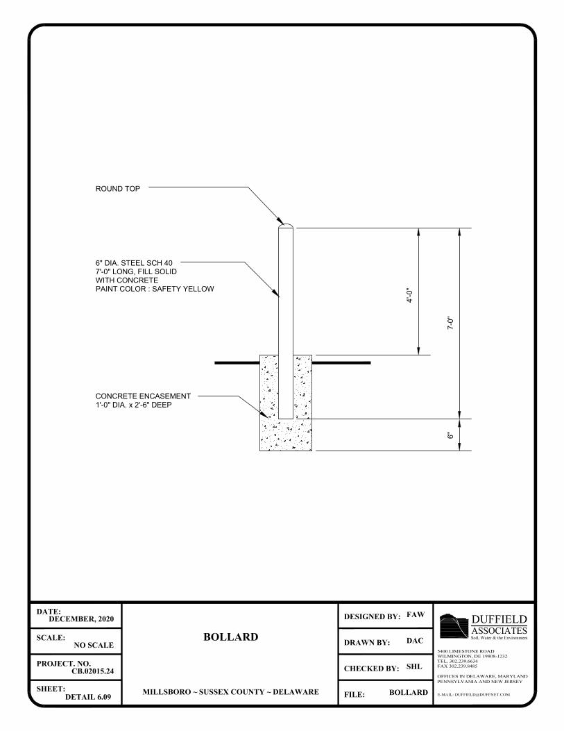
7-0
"
4'-0
"
ROUND TOP
WITH CONCRETE
6" DIA. STEEL SCH 40
7'-0" LONG, FILL SOLID
PAINT COLOR : SAFETY YELLOW
6"
CONCRETE ENCASEMENT
1'-0" DIA. x 2'-6" DEEP
E-MAIL: [email protected]
OFFICES IN DELAWARE, MARYLANDPENNSYLVANIA AND NEW JERSEY
CHECKED BY:
DRAWN BY:
FILE:
DESIGNED BY:
SHEET:
PROJECT. NO.
SCALE:
DATE:
ASSOCIATESDUFFIELDSoil, Water & the Environment
5400 LIMESTONE ROADWILMINGTON, DE 19808-1232TEL. 302.239.6634FAX 302.239.8485
BOLLARD
MILLSBORO ~ SUSSEX COUNTY ~ DELAWARE
DECEMBER, 2020
NO SCALE
CB.02015.24
DETAIL 6.09
FAW
DAC
SHL
BOLLARD
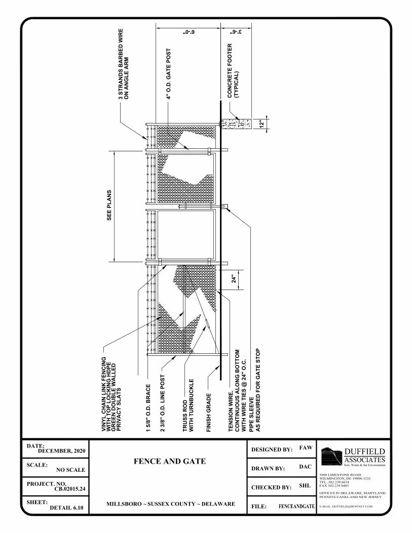
E-MAIL: [email protected]
OFFICES IN DELAWARE, MARYLANDPENNSYLVANIA AND NEW JERSEY
CHECKED BY:
DRAWN BY:
FILE:
DESIGNED BY:
SHEET:
PROJECT. NO.
SCALE:
DATE:
ASSOCIATESDUFFIELDSoil, Water & the Environment
5400 LIMESTONE ROADWILMINGTON, DE 19808-1232TEL. 302.239.6634FAX 302.239.8485
FENCE AND GATE
MILLSBORO ~ SUSSEX COUNTY ~ DELAWARE
DECEMBER, 2020
NO SCALE
CB.02015.24
DETAIL 6.10
FAW
DAC
SHL
FENCEANDGATE
CO
NC
RE
TE
F
OO
TE
R
(T
YP
IC
AL
)
PIP
E S
LE
EV
E
AS
R
EQ
UIR
ED
F
OR
G
AT
E S
TO
P
TE
NS
IO
N W
IR
E,
CO
NT
IN
UO
US
A
LO
NG
B
OT
TO
M
WIT
H W
IR
E T
IE
S @
2
4" O
.C
.
WIT
H T
UR
NB
UC
KL
E
2 3
/8
" O
.D
. L
IN
E P
OS
T
1 5
/8
" O
.D
. B
RA
CE
4" O
.D
. G
AT
E P
OS
T
24
"
SE
E P
LA
NS
6'-0" 3'-6"
12
"
FIN
IS
H G
RA
DE
3 S
TR
AN
DS
B
AR
BE
D W
IR
E
ON
A
NG
LE
A
RM
VIN
YL
C
HA
IN
L
IN
K F
EN
CIN
G
WIT
H T
OP
L
OC
KIN
G H
DP
E
GR
EE
N D
OU
BL
E W
AL
LE
D
PR
IV
AC
Y S
LA
TS
TR
US
S R
OD
AutoCAD SHX Text
X
AutoCAD SHX Text
X
AutoCAD SHX Text
X
AutoCAD SHX Text
X
AutoCAD SHX Text
X
AutoCAD SHX Text
X
AutoCAD SHX Text
X
AutoCAD SHX Text
X
AutoCAD SHX Text
X
AutoCAD SHX Text
X
AutoCAD SHX Text
X
AutoCAD SHX Text
X
AutoCAD SHX Text
X
AutoCAD SHX Text
X
AutoCAD SHX Text
X
AutoCAD SHX Text
X
AutoCAD SHX Text
X
AutoCAD SHX Text
X
AutoCAD SHX Text
X
AutoCAD SHX Text
X
AutoCAD SHX Text
X
AutoCAD SHX Text
X
AutoCAD SHX Text
X
AutoCAD SHX Text
X
AutoCAD SHX Text
X
AutoCAD SHX Text
X
AutoCAD SHX Text
X
AutoCAD SHX Text
X
AutoCAD SHX Text
X
AutoCAD SHX Text
X
AutoCAD SHX Text
X
AutoCAD SHX Text
X
AutoCAD SHX Text
X
AutoCAD SHX Text
X
AutoCAD SHX Text
X
AutoCAD SHX Text
X
AutoCAD SHX Text
X
AutoCAD SHX Text
X
AutoCAD SHX Text
X
AutoCAD SHX Text
X
AutoCAD SHX Text
X
AutoCAD SHX Text
X
AutoCAD SHX Text
X
AutoCAD SHX Text
X
AutoCAD SHX Text
X
AutoCAD SHX Text
X
AutoCAD SHX Text
X
AutoCAD SHX Text
X
AutoCAD SHX Text
X
AutoCAD SHX Text
X
AutoCAD SHX Text
X
AutoCAD SHX Text
X
AutoCAD SHX Text
X
AutoCAD SHX Text
X
AutoCAD SHX Text
X
AutoCAD SHX Text
X
AutoCAD SHX Text
X
AutoCAD SHX Text
X
AutoCAD SHX Text
X
AutoCAD SHX Text
X
AutoCAD SHX Text
X
AutoCAD SHX Text
X
AutoCAD SHX Text
X
AutoCAD SHX Text
X
AutoCAD SHX Text
X
AutoCAD SHX Text
X
AutoCAD SHX Text
X
AutoCAD SHX Text
X
AutoCAD SHX Text
X
AutoCAD SHX Text
X
AutoCAD SHX Text
X
AutoCAD SHX Text
X
AutoCAD SHX Text
X
AutoCAD SHX Text
X
AutoCAD SHX Text
X
AutoCAD SHX Text
X
AutoCAD SHX Text
X
AutoCAD SHX Text
X
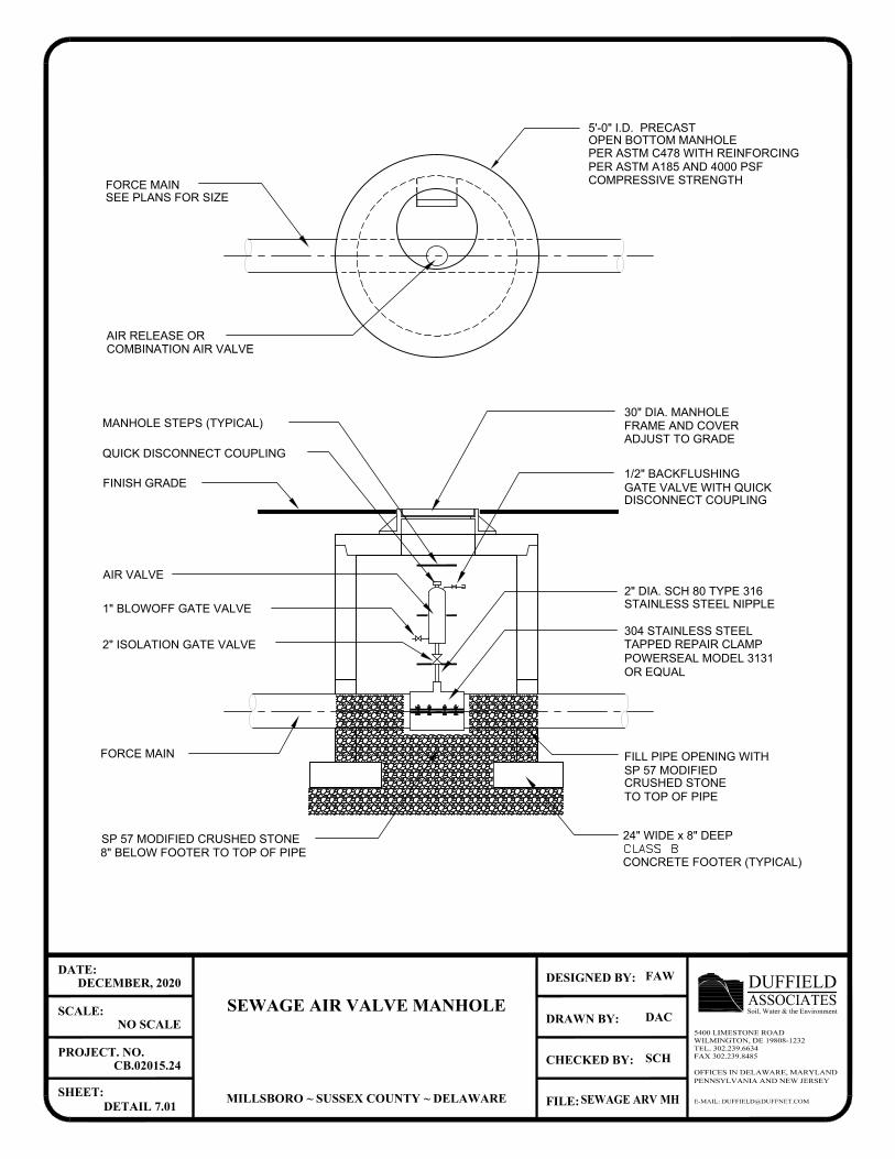
8" BELOW FOOTER TO TOP OF PIPE
SP 57 MODIFIED CRUSHED STONE
FORCE MAIN
QUICK DISCONNECT COUPLING
MANHOLE STEPS (TYPICAL)
AIR VALVE
2" ISOLATION GATE VALVE
1" BLOWOFF GATE VALVE
FINISH GRADE
AIR RELEASE OR
FORCE MAIN
SEE PLANS FOR SIZE
COMBINATION AIR VALVE
CRUSHED STONE
TO TOP OF PIPE
FILL PIPE OPENING WITH
24" WIDE x 8" DEEP
2" DIA. SCH 80 TYPE 316
STAINLESS STEEL NIPPLE
304 STAINLESS STEEL
TAPPED REPAIR CLAMP
POWERSEAL MODEL 3131
DISCONNECT COUPLING
GATE VALVE WITH QUICK
1/2" BACKFLUSHING
30" DIA. MANHOLE
OR EQUAL
ADJUST TO GRADE
5'-0" I.D. PRECAST
PER ASTM C478 WITH REINFORCING
COMPRESSIVE STRENGTH
PER ASTM A185 AND 4000 PSF
OPEN BOTTOM MANHOLE
FRAME AND COVER
SP 57 MODIFIED
CONCRETE FOOTER (TYPICAL)
E-MAIL: [email protected]
OFFICES IN DELAWARE, MARYLANDPENNSYLVANIA AND NEW JERSEY
CHECKED BY:
DRAWN BY:
FILE:
DESIGNED BY:
SHEET:
PROJECT. NO.
SCALE:
DATE:
ASSOCIATESDUFFIELDSoil, Water & the Environment
5400 LIMESTONE ROADWILMINGTON, DE 19808-1232TEL. 302.239.6634FAX 302.239.8485
SEWAGE AIR VALVE MANHOLE
MILLSBORO ~ SUSSEX COUNTY ~ DELAWARE
DECEMBER, 2020
NO SCALE
CB.02015.24
DETAIL 7.01
FAW
DAC
SCH
SEWAGE ARV MH
AutoCAD SHX Text
CLASS B
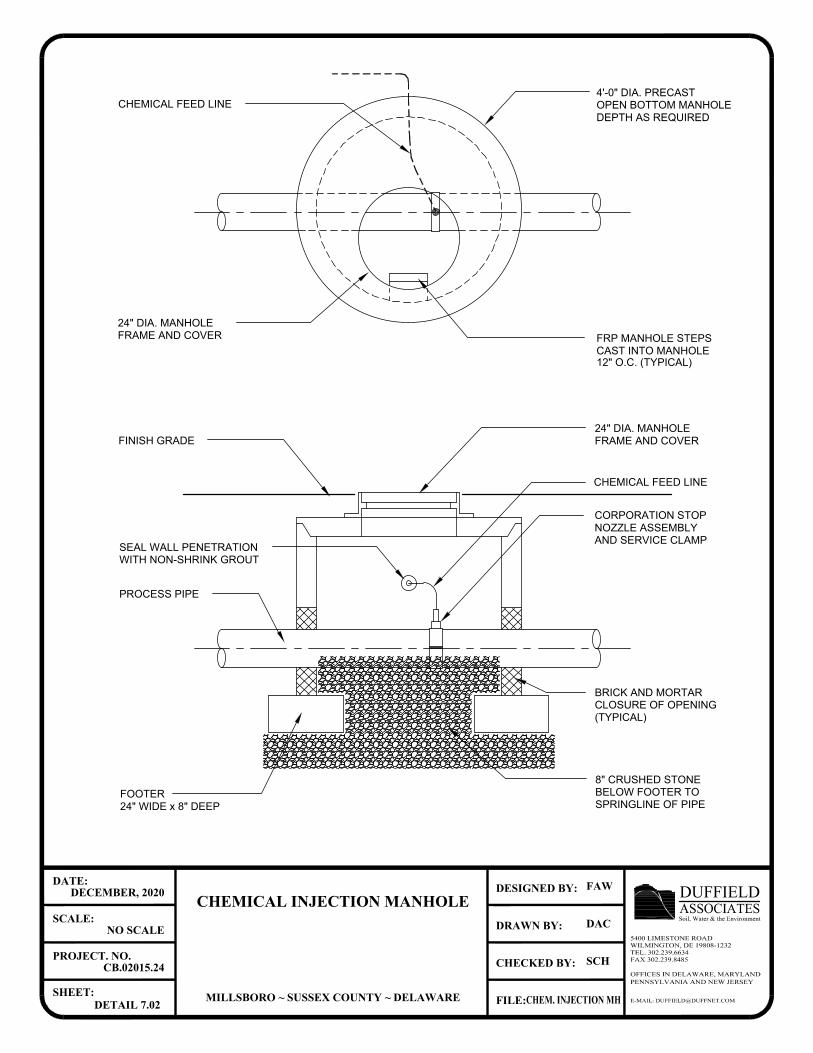
24" WIDE x 8" DEEP
CHEMICAL FEED LINE
FOOTER
PROCESS PIPE
FINISH GRADE
BRICK AND MORTAR
CLOSURE OF OPENING
SPRINGLINE OF PIPE
BELOW FOOTER TO
8" CRUSHED STONE
(TYPICAL)
AND SERVICE CLAMP
CORPORATION STOP
FRAME AND COVER
CHEMICAL FEED LINE
DEPTH AS REQUIRED
OPEN BOTTOM MANHOLE
4'-0" DIA. PRECAST
NOZZLE ASSEMBLY
24" DIA. MANHOLE
FRAME AND COVER
24" DIA. MANHOLE
FRP MANHOLE STEPS
CAST INTO MANHOLE
12" O.C. (TYPICAL)
WITH NON-SHRINK GROUT
SEAL WALL PENETRATION
E-MAIL: [email protected]
OFFICES IN DELAWARE, MARYLANDPENNSYLVANIA AND NEW JERSEY
CHECKED BY:
DRAWN BY:
FILE:
DESIGNED BY:
SHEET:
PROJECT. NO.
SCALE:
DATE:
ASSOCIATESDUFFIELDSoil, Water & the Environment
5400 LIMESTONE ROADWILMINGTON, DE 19808-1232TEL. 302.239.6634FAX 302.239.8485
CHEMICAL INJECTION MANHOLE
MILLSBORO ~ SUSSEX COUNTY ~ DELAWARE
DECEMBER, 2020
NO SCALE
CB.02015.24
DETAIL 7.02
FAW
DAC
SCH
CHEM. INJECTION MH

E-MAIL: [email protected]
OFFICES IN DELAWARE, MARYLANDPENNSYLVANIA AND NEW JERSEY
CHECKED BY:
DRAWN BY:
FILE:
DESIGNED BY:
SHEET:
PROJECT. NO.
SCALE:
DATE:
ASSOCIATESDUFFIELDSoil, Water & the Environment
5400 LIMESTONE ROADWILMINGTON, DE 19808-1232TEL. 302.239.6634FAX 302.239.8485
FORCE MAIN DISCHARGE MANHOLE
MILLSBORO ~ SUSSEX COUNTY ~ DELAWARE
DECEMBER, 2020
NO SCALE
CB.02015.24
DETAIL 7.03
SMC
SMC
SHL
SEWAGE ARV MH
5'-0"
MJ REDUCER
FORCE MAIN
PIPE TO MANHOLE
SEAL WITH LINK-SEAL
EXPANSION TO BE MINIMUM
TWO TIMES FORCE MAIN PIPE AREA
SEE TABLE THIS SHEET
BRICK FLOW OR
PRECAST CHANNEL
NOTE:
COAT INTERIOR SURFACES OF MANHOLE WITH AMINE CURED EPOXY,
TWO COATS 16.0 TO 24.0 MIL. DPT TOTAL
MANHOLE
SEE DETAIL 5.01
FM DIA. (IN) DIA. EXP. (IN)
4
6
8
10
12
14
6
10
12
14
18
20
TOP OF BENCH
TYPICAL FOR ALL OPENINGS
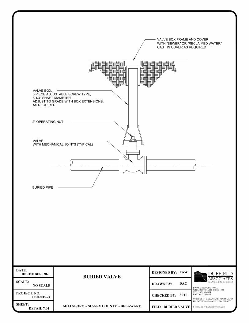
AS REQUIRED
ADJUST TO GRADE WITH BOX EXTENSIONS,
5 1/4" SHAFT DIAMETER,
3 PIECE ADJUSTABLE SCREW TYPE,
VALVE BOX,
WITH "SEWER" OR "RECLAIMED WATER"
VALVE BOX FRAME AND COVER
2" OPERATING NUT
VALVE
WITH MECHANICAL JOINTS (TYPICAL)
BURIED PIPE
E-MAIL: [email protected]
OFFICES IN DELAWARE, MARYLANDPENNSYLVANIA AND NEW JERSEY
CHECKED BY:
DRAWN BY:
FILE:
DESIGNED BY:
SHEET:
PROJECT. NO.
SCALE:
DATE:
ASSOCIATESDUFFIELDSoil, Water & the Environment
5400 LIMESTONE ROADWILMINGTON, DE 19808-1232TEL. 302.239.6634FAX 302.239.8485
BURIED VALVE
MILLSBORO ~ SUSSEX COUNTY ~ DELAWARE
DECEMBER, 2020
NO SCALE
CB.02015.24
DETAIL 7.04
FAW
DAC
SCH
BURIED VALVE
CAST IN COVER AS REQUIRED
Related Documents