The Product Safety Engineering Newsletter Vol. 3, No. 4 December 2007 President’s Message What’s Inside President’s Message .......................... 1 Officers of the IEEE PSES................ 2 Chapter Activities.................................... 4 Technicially Speaking .......................... 6 Safety Considerations For Liquid Filled Heat Sinks ................................. 24 News and Notes ............................... 28 Continued on Page 3 Henry Benitez Hello Product Safety Engineering Society Members, It has been a remarkable experience for me to serve as president of the Product Safety Engineering Society for the past 2 years. I have enjoyed being part of the growth of this Society. I have enjoyed working with the many wonderful PSES volunteers and watching their personal growth as leaders of this great organization. Mr. Jim Bacher will be the new PSES President starting in 2008. Jim has been actively involved with the PSES and former PSTC for many years. Jim will be an excellent leader to take this organization to the next level as we push our membership to greater than 1000, develop a PSES journal or magazine, develop more technical committees and make more significant progress with PSES conferences and workshops. I enjoyed seeing so many of you at the PSES Product Compliance Symposium held this past October in Longmont, Colorado. The feedback has been very positive! I would like to thank August (Gus) Schaefer, UL Vice President, for his exciting keynote address. Exhibits increased over 100% this year and I expect to see similar increases in years to come as vendors become aware of the PSES event. 2008 will be the 5 th anniversary for the Product Safety Engineering Society. The 5 th annual PSES Symposium will be held in Austin, Texas. Austin has an active PSES Chapter and some enthusiastic volunteers to help organize the symposium. I look forward to this event as I expect that it will be spectacular.

Welcome message from author
This document is posted to help you gain knowledge. Please leave a comment to let me know what you think about it! Share it to your friends and learn new things together.
Transcript
Vol. 3 No. 4 Page 1IEEE PSES Product Safety Engineering Newsletter
TheProductSafetyEngineeringNewsletter
Vol. 3, No. 4 December 2007
President’s Message
What’s InsidePresident’s Message..........................1
Officers of the IEEE PSES................2
Chapter Activities....................................4
Technicially Speaking.......................... 6
Safety Considerations For Liquid Filled Heat Sinks................................. 24
News and Notes............................... 28
Continued on Page 3
Henry Benitez
Hello Product Safety Engineering Society Members,
It has been a remarkable experience for me toserve as president of the Product SafetyEngineering Society for the past 2 years. I haveenjoyed being part of the growth of this Society.I have enjoyed working with the many wonderfulPSES volunteers and watching their personalgrowth as leaders of this great organization. Mr.Jim Bacher will be the new PSES Presidentstarting in 2008. Jim has been actively involvedwith the PSES and former PSTC for many years.Jim will be an excellent leader to take thisorganization to the next level as we push ourmembership to greater than 1000, develop aPSES journal or magazine, develop moretechnical committees and make more significantprogress with PSES conferences and workshops.
I enjoyed seeing so many of you at the PSESProduct Compliance Symposium held this pastOctober in Longmont, Colorado. The feedbackhas been very positive! I would like to thankAugust (Gus) Schaefer, UL Vice President, forhis exciting keynote address. Exhibits increased
over 100% this year and I expect to see similarincreases in years to come as vendors becomeaware of the PSES event.
2008 will be the 5th anniversary for the ProductSafety Engineering Society. The 5th annual PSESSymposium will be held in Austin, Texas. Austinhas an active PSES Chapter and someenthusiastic volunteers to help organize thesymposium. I look forward to this event as Iexpect that it will be spectacular.
Vol. 3 No. 4 Page 2 IEEE PSES Product Safety Engineering Newsletter
The
ProductSafetyEngineeringNewsletter
The Product Safety Engineering Newsletter is published by the IEEE Product Safety EngineeringSociety. No part of this newsletter may be reproduced without written permission of the authors. Allrights to the article remain with the authors.
Opinions expressed in this newsletter are those of the authors and do not necessarily represent theopinions of the Society or any of its members. Indeed, there may be and often are substantialdisagreements with some of the opinions expressed by the authors.
Copyright 2007 IEEE Product Safety Engineering Society.
IEEE PSES Officers
Newsletter Committee
IEEE PSES Web Siteshttp://www.ieee-pses.org/http://www.ieee-pses.org/symposium/http://www.ieeecommunities.org/emc-pstchttp://www.ieee-pses.org/emc-pstc.htmlhttp://www.ieee-pses.org/newsletters.htmlhttp://www.ieee-pses.org/pses.html
Executive Committee Name TermPresident Henry Benitez (06-07)Past President Mark Montrose (06-07)President Elect Jim Bacher (07)Secretary Daniece Carpenter (07-08)Treasurer Murlin Marks (07-08)Vice President - Communications Dan Roman (07-08)Vice President - Member Services Ken Thomas (07-08)Vice President - Technical Activities Jack Burns (07-08)Vice President - Conferences Richard Georgerian (07-08)
Directors At LargeTerm Expires 12/07 Term Expires 12/08 Term Expires 12/09 Ex Officio (without vote)Jim Bacher Jack Burns Daniece Carpenter Chapter Chairs
Murlin Marks Daniel Nachtigall Standing Committee ChairsBansi Patel Richard Pescatore Richard Georgerian IEEE HQDan Roman Ken Thomas Elya Joffe IEEE TAB Division VI Director
Editor:Gary Weidner 1-563-557-0717 (v) 1-563.557.0725 (fax) [email protected]
Co-Editors:Michael S. Morse Ph. D. [email protected] Nute [email protected] MedoraLal BahraLingfeng ChenEric SklarLauren Crane
News & Notes:Your name here
Chapter Acitivities:Stefan Mozar +86 139 2373 9161 (China Mobile) +852 9128 7947 (HK Mobile) [email protected]
Page Layout:Jim Bacher 1-937.865-2020(v) 1-937.865.2048 (fax) [email protected]
Vol. 3 No. 4 Page 3IEEE PSES Product Safety Engineering Newsletter
Tip: Best way to get your boss to approve yourtrip to the 2008 Symposium on ComplianceEngineering is to submit a paper that gets ac-cepted for the symposium! Or volunteer andtell him you have to be there!
I welcome Doug Nix and Peter Tarver as newmembers to the PSES Board of Directors. Theirenthusiasm and new ideas will be a welcomeaddition as the PSES moves forward. Jim Bacherand Mark Montrose were also elected to anotherterm on the Board. I would like to thank all Boardmembers and PSES volunteers for their supportin making my job easy for the past two years!
Sincerely,
Henry Benitez
IEEE Product Safety Engineering [email protected]

Vol. 3 No. 4 Page 4 IEEE PSES Product Safety Engineering Newsletter
Rochester NY Chapter Boston Chapter
Chairman : John [email protected]
Chairman : James [email protected]
Orange County Chapter
www.ieee.org/oc-psesChairman Paul Herrick
Chapter Safety Probes
Central Texas Chapter
Oregon Chapter
Santa Clara Chapter
Chicago Chapter
Chairman : Steve Baldwin [email protected]
Chairman : Ken [email protected]
Chairman : Dean [email protected]
Chairman : Daniece [email protected]
Vol. 3 No. 4 Page 5IEEE PSES Product Safety Engineering Newsletter
Richard Georgerianvoice: (303) 833-2327e-mail: [email protected]
People Looking To Start Chapters
Mike Cantwell, PESr. Account RepresentativeIntertek ETL SEMKO420 N. Dorothy Dr.Richardson, TX 75081Tel: 972-238-5591 x107Fax: 972-238-1860e-mail: [email protected] Paschetag [email protected]
Denver Colorodo Dallas Texas
Vancouver Chapter
Taipei Taiwan Chapter
Chairman : Moshe [email protected]
IEEE PSES International Chapters
Chairman: Steven [email protected]
Chairman : Zenon [email protected]
Israel Chapter
Doug [email protected]: (519) 729-5704FaX: (519) 653-1318
Toronto Ontario
Southern California
North Carolina
Charles Bayhi ([email protected]).
Warren Fields ([email protected]).

Vol. 3 No. 4 Page 6 IEEE PSES Product Safety Engineering Newsletter
Technically Speaking
by Richard NuteProduct Safety ConsultantSan DiegoSeptember, 2007
ELECTRIC SHOCK AND ELECTRIC SHOCK SAFEGUARDSIN
DIGITAL CAMERA FLASH CIRCUITSIntroduction.
A few days ago, a CTL Provisional Decision Sheet was brought to my attention. The CTL is the “Commit-tee of Testing Laboratories,” a part of the IECEE. CTL Decision Sheets and Provisional Decision Sheetsdocument the answers (“decisions”) to standards interpretation questions raised by CTL members. (1)
This particular Provisional Decision Sheet is in response to three questions about flash circuits in digitalcameras. Flash tubes operate on high voltage. So, we have a battery-operated device with internal highvoltage assumed to be capable of rendering an electric shock.
We’ll look at the questions, examine the schematic, determine what parts could render an electric shock,and then identify the necessary safeguards and the safeguard requirements.
This discussion is for a consumer-grade camera with integral flash. While the principles of circuit opera-tion apply to most flash circuits, the safety principles apply to small, low-power consumer-grade equip-ment.
Provisional Decision Sheet questions.
Here are the questions, answers, and explanatory note as published by the CTL in the Provisional DataSheet. The standard in question is IEC 60950-1, and the questions are in regard to sub-clauses 1.2.4.2(Class II Equipment), 1.2.6.4 (Electrical Enclosure), 1.2.8.6 (ELV Circuit), and 2.4 (Limited current cir-cuits).
Vol. 3 No. 4 Page 7IEEE PSES Product Safety Engineering Newsletter
Continued on Page 8
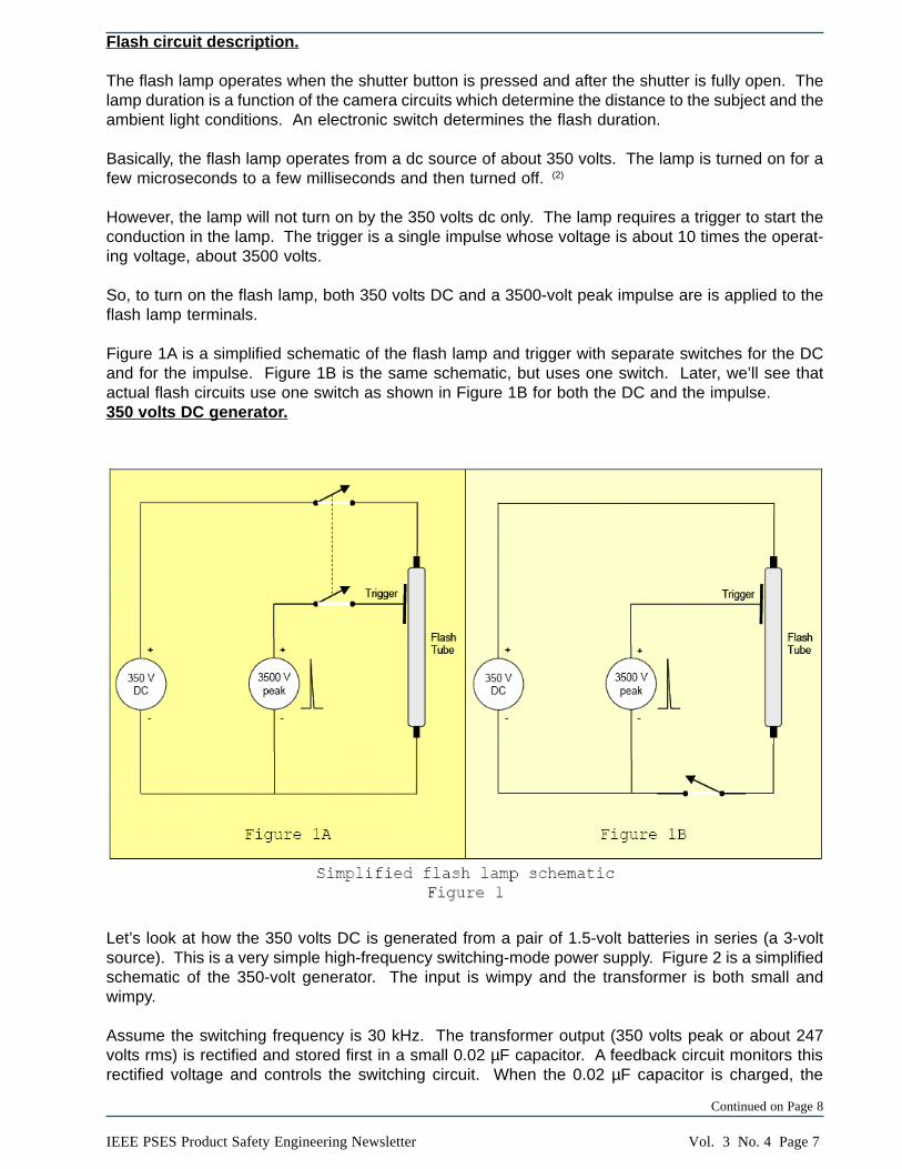
Flash circuit description.
The flash lamp operates when the shutter button is pressed and after the shutter is fully open. Thelamp duration is a function of the camera circuits which determine the distance to the subject and theambient light conditions. An electronic switch determines the flash duration.
Basically, the flash lamp operates from a dc source of about 350 volts. The lamp is turned on for afew microseconds to a few milliseconds and then turned off. (2)
However, the lamp will not turn on by the 350 volts dc only. The lamp requires a trigger to start theconduction in the lamp. The trigger is a single impulse whose voltage is about 10 times the operat-ing voltage, about 3500 volts.
So, to turn on the flash lamp, both 350 volts DC and a 3500-volt peak impulse are is applied to theflash lamp terminals.
Figure 1A is a simplified schematic of the flash lamp and trigger with separate switches for the DCand for the impulse. Figure 1B is the same schematic, but uses one switch. Later, we’ll see thatactual flash circuits use one switch as shown in Figure 1B for both the DC and the impulse.350 volts DC generator.
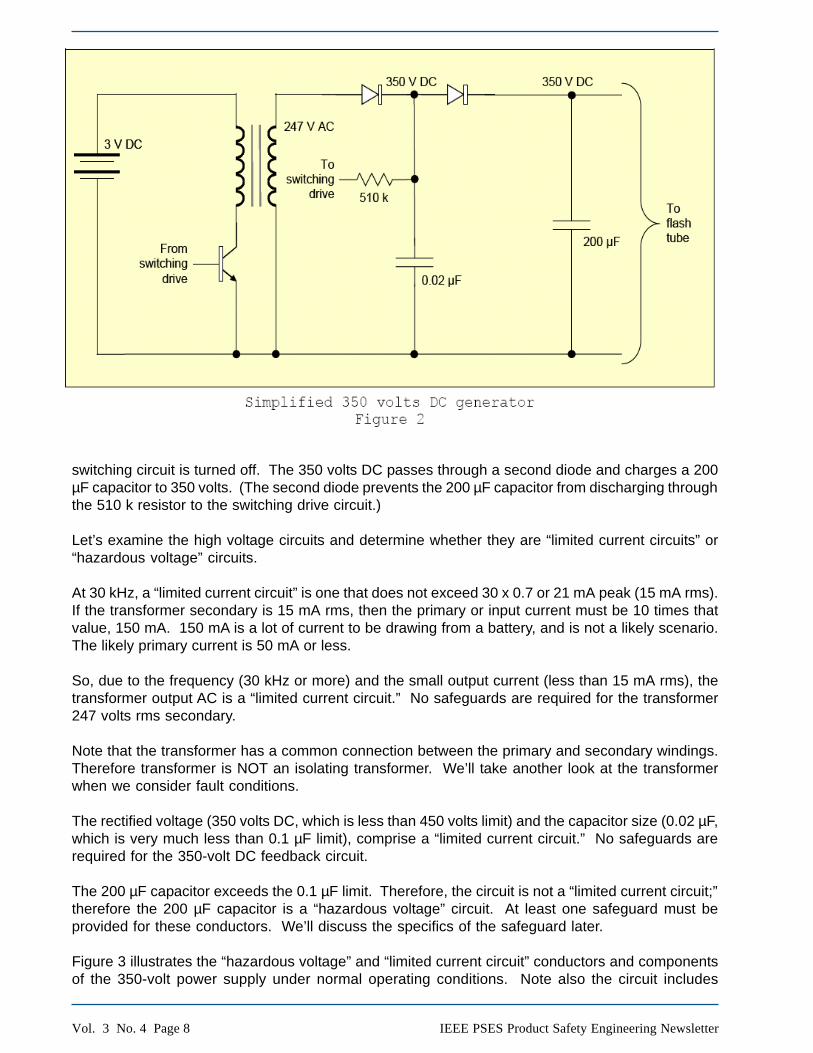
Let’s look at how the 350 volts DC is generated from a pair of 1.5-volt batteries in series (a 3-voltsource). This is a very simple high-frequency switching-mode power supply. Figure 2 is a simplifiedschematic of the 350-volt generator. The input is wimpy and the transformer is both small andwimpy.
Assume the switching frequency is 30 kHz. The transformer output (350 volts peak or about 247volts rms) is rectified and stored first in a small 0.02 µF capacitor. A feedback circuit monitors thisrectified voltage and controls the switching circuit. When the 0.02 µF capacitor is charged, the
Vol. 3 No. 4 Page 8 IEEE PSES Product Safety Engineering Newsletter
switching circuit is turned off. The 350 volts DC passes through a second diode and charges a 200µF capacitor to 350 volts. (The second diode prevents the 200 µF capacitor from discharging throughthe 510 k resistor to the switching drive circuit.)
Let’s examine the high voltage circuits and determine whether they are “limited current circuits” or“hazardous voltage” circuits.
At 30 kHz, a “limited current circuit” is one that does not exceed 30 x 0.7 or 21 mA peak (15 mA rms).If the transformer secondary is 15 mA rms, then the primary or input current must be 10 times thatvalue, 150 mA. 150 mA is a lot of current to be drawing from a battery, and is not a likely scenario.The likely primary current is 50 mA or less.
So, due to the frequency (30 kHz or more) and the small output current (less than 15 mA rms), thetransformer output AC is a “limited current circuit.” No safeguards are required for the transformer247 volts rms secondary.
Note that the transformer has a common connection between the primary and secondary windings.Therefore transformer is NOT an isolating transformer. We’ll take another look at the transformerwhen we consider fault conditions.
The rectified voltage (350 volts DC, which is less than 450 volts limit) and the capacitor size (0.02 µF,which is very much less than 0.1 µF limit), comprise a “limited current circuit.” No safeguards arerequired for the 350-volt DC feedback circuit.
The 200 µF capacitor exceeds the 0.1 µF limit. Therefore, the circuit is not a “limited current circuit;”therefore the 200 µF capacitor is a “hazardous voltage” circuit. At least one safeguard must beprovided for these conductors. We’ll discuss the specifics of the safeguard later.
Figure 3 illustrates the “hazardous voltage” and “limited current circuit” conductors and componentsof the 350-volt power supply under normal operating conditions. Note also the circuit includes
Simplified 350 volts DC generatorFigure 2

Vol. 3 No. 4 Page 9IEEE PSES Product Safety Engineering Newsletter
“extra-low voltage.” And, note that all voltages are with respect to the common wire. A battery-operated equipment does not have any connection to earth. This will be significant when we look atthe electric shock circuit.IEC 60950-1, sub-clause requires “limited current circuits” to meet the criteria under both normaloperating conditions and single fault conditions.
As can be seen in these circuits, component short-circuits are worst-case. Open-circuits are not ofany consequence.
Figure 4 illustrates the DC generator “hazardous voltage,” “limited current circuit,” and “extra-lowvoltage” conductors and components under single fault conditions. The fault is indicated by the redlightning bolt. The conductors that become “hazardous voltage” as a result of the fault are high-lighted in a lighter color.
The switching transistor in the primary circuit switches on and off. So, we need not fault the transis-tor since its normal operation is both short (on) and open (off). When the transistor is open, there isno current in the transformer primary and therefore no output in the secondary. When the transistoris shorted, DC flows in the primary and therefore no output in the secondary. Conclusion: In thecase of a fault of the switching transistor, the current from the “limited current circuit” is 0 mA. So, theAC secondary is a “limited current circuit” under both normal operating conditions and single faultconditions.
The transformer is not an isolating transformer. Nevertheless, we should consider a primary-to-secondary short. When this happens, there is no output because the secondary becomes anotherprimary. In the case of a fault of the transformer, the current from the secondary winding is 0 mA andis a “limited current circuit” under single fault conditions.
If first rectifier diode should fail open, there is no output to the DC “limited current circuit.” If the diode
Continued on Page 10

Vol. 3 No. 4 Page 10 IEEE PSES Product Safety Engineering Newsletter
should fail short, then the DC “limited current circuit” becomes an AC “limited current circuit.” In thecase of a fault of the first rectifier diode, the current from the “limited current circuit” is either 0 mA(open diode) or less than 15 mA AC (shorted diode) at 30 kHz.
If the second diode should fail open, then there is no output to the 200 µF capacitor and the chargevoltage is zero. If the second diode should fail short, then, due to the charged 200µF capacitor, the“limited current circuit” DC on the supply side of the diode becomes “hazardous voltage.” The 510 kresistor between the “limited current circuit” DC and the switching drive circuit renders the switchingdrive circuit as a “limited current circuit” (I = 350/510 k or 0.7 mA DC). (The limit for a DC “limitedcurrent circuit” is 2 mA DC.)
We conclude that, under single fault conditions, the only hazardous voltage circuits are those shownin Figure 4.
3500 volts impulse generator.
Now let’s see how the 3500-volt impulse is generated.
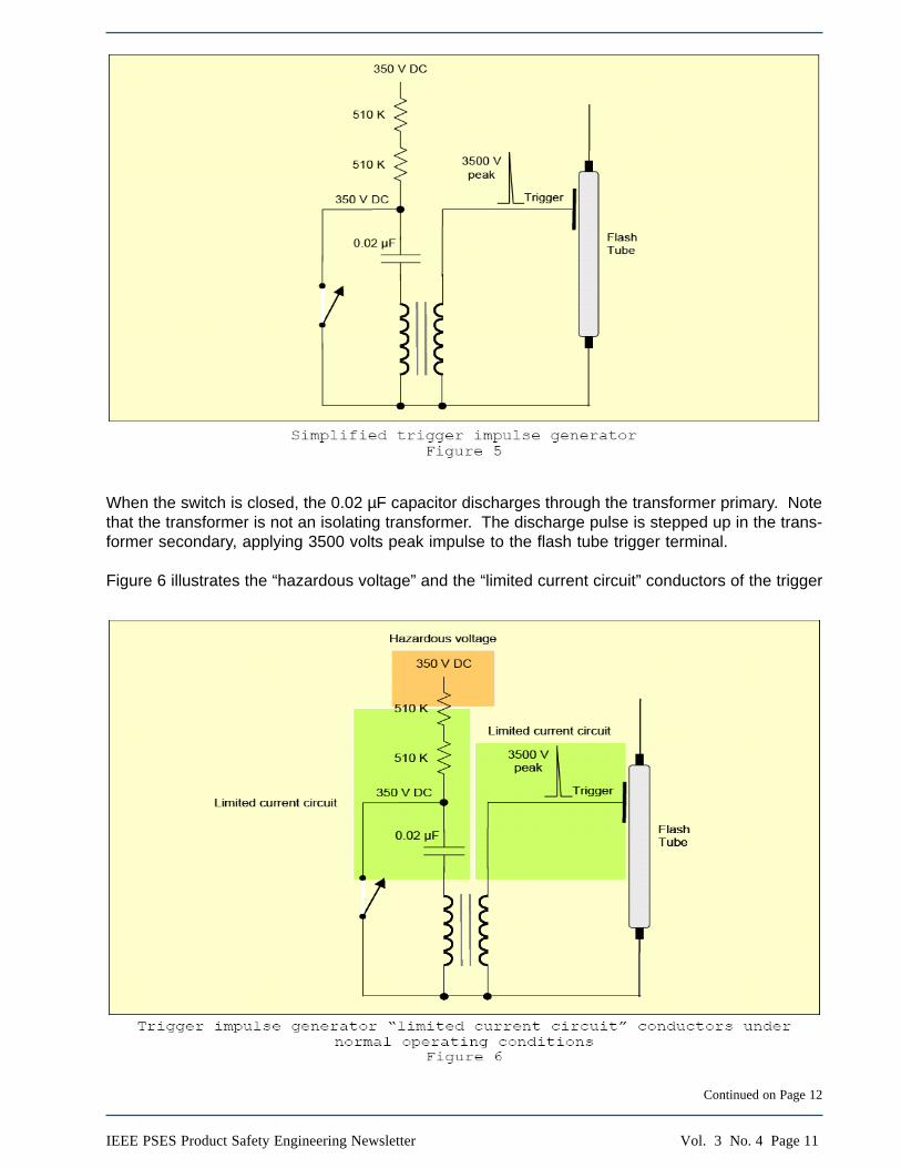
The impulse generator circuit, Figure 5, consists of resistors, capacitor, and transformer primary inseries. The 0.02 µF capacitor is charged from the 350 volts DC through the two 510 k resistors to350 volts.
Figure 5 illustrates the trigger impulse generator. When the switch is open, the 0.02 µF capacitor ischarged from the 350 volts DC through the two 510 k resistors. The charge is 350 volts. The voltage(350 volts DC) and the capacitance (0.02 µF) are less than the limits of 450 volts and 0.1 µF, so thecircuit is a “limited current circuit.”
Vol. 3 No. 4 Page 11IEEE PSES Product Safety Engineering Newsletter
Continued on Page 12
When the switch is closed, the 0.02 µF capacitor discharges through the transformer primary. Notethat the transformer is not an isolating transformer. The discharge pulse is stepped up in the trans-former secondary, applying 3500 volts peak impulse to the flash tube trigger terminal.
Figure 6 illustrates the “hazardous voltage” and the “limited current circuit” conductors of the trigger
Simplified trigger impulse generator Figure 5
Trigger impulse generator “limited current circuit” conductors under normal operating conditionsFigure 6

Vol. 3 No. 4 Page 12 IEEE PSES Product Safety Engineering Newsletter
impulse generator.
Note that if the primary is a “limited current circuit,” then so too is the secondary. The total amount ofenergy in a system is a constant. Therefore, the secondary circuit energy must be the same or lessthan the primary circuit energy. Therefore, the secondary circuit is a “limited current circuit.” Nosafeguards are required for the trigger impulse even though it is 3500 volts.
Furthermore, one 510 k resistor limits the current from 350 volts dc to about 0.7 mA DC. The limit fora DC “limited current circuit” is 2 mA DC. So, both the charging circuit and the charged capacitorcomprise “limited current circuits.”
Another way to evaluate the 3500-volt trigger impulse generator is to consider an equivalent sec-ondary (high-voltage) circuit. If the transformer is a 1:10 step-up transformer, then the 0.02 µFcapacitor as seen from the secondary will appear to be 1/10 of 0.02 or 0.002 µF charged to 3500volts. For voltages exceeding 450 volts, the capacitance of a “limited current circuit” must not ex-ceed 45/3500 or 0.0128 µF. The reflected capacitance, 0.002 µF is less than 0.0128 µF, so thetrigger impulse generator is a “limited current circuit.”
Figure 7 illustrates the “limited current circuits” under single fault conditions. Note that the only faultis the 510 k resistor between the “hazardous voltage” and the “limited current circuit. Only theconductor between the two 510 k resistors is at “hazardous voltage” under single fault conditions.When the first 510 k resistor is shorted, the second 510 k resistor limits the current to the remainder
of the circuit.
Flash tube switch circuit.
Now, we’ll examine the circuit that switches the 350 volts DC to the flash tube. See Figure 8.
Trigger impulse generator “limited current circuit” conductors under single fault conditions Figure 7

Vol. 3 No. 4 Page 13IEEE PSES Product Safety Engineering Newsletter
Continued on Page 16

Vol. 3 No. 4 Page 14 IEEE PSES Product Safety Engineering Newsletter
It’s time to relax and enjoy the fruits of your dailyefforts! The IEEE Financial Advantage Programprovides the solutions you need to take controlof your life and maintain your independence –whether you are starting a business at home,investing for today or for retirement, planning adream vacation, or all of the above!
IEEE Financial Advantage Program representa-tives will answer questions and guide you tomore detailed information. Let them help youfind the programs that are right for you:
• Insurance Programs • Financial Services • Home Services • Business Services
In the US and Canada
Call +1 800 GET IEEE (438 4333)Outside the US and Canada call +1 732 981 0060
We’ve got you covered!
All your solutions under one roof!Visit www.ieee.org/fapEmail [email protected]
534-Yd FAP Home Half BW 2/3/05 3:15 PM Page 1

Vol. 3 No. 4 Page 15IEEE PSES Product Safety Engineering Newsletter
Advantages of Membershipin the IEEE PSES
Makes you part of a community where you will:• Network with technical experts at local events and industry conferences.• Receive discounts on Society conferences and symposiums registration fees.• Participate in education and career development.• Address product safety engineering as an applied science.• Have access to a virtual community forum for safety engineers and technical professionals.• Promotion and coordination of Product Safety Engineering activities with multiple IEEE Societies.• Provide outreach to interested engineers, students and professionals.• Have access to Society Publications.
E-Mail List: http://www.ieee-pses.org/emc-pstc.htmlVirtual Community: http://www.ieeecommunities.org/emc-pstc
Symposium: http://www.ieee-pses.org/symposium/
Membership: The society ID for renewal or application is “043-0431”. Yearly society fee is US $35.
UL University OffersIEEE PSES Members15 Percent Discount
UL University (ULU) has established a discount code which will provide all IEEE-PSES members with a 15 percent discount off the price of all ULU instructor-ledworkshops, online programs, videos, books, and other services/products offeredunder the ULU brand. The discount is automatically applied during registration orpurchase of ULU products. Registration or product purchase can be accomplishedonline at www.uluniversity.com or by calling 888-503-5536 in the U.S. or thecountry-specific number posted on the ULU website.
To receive the discount, members must enter or mention the discount code foundin the Members Only section of the PSES website.
If you or any member has specific questions regarding ULU products or services,please call or email me or call the local country specific number posted on the ULUniversity website.
Tony RobertsonManager − Customer Training
IEEE PSES Membership savings

Vol. 3 No. 4 Page 16 IEEE PSES Product Safety Engineering Newsletter
The 350 volts DC is connected to one end of the flash tube. When the switch is closed the energystored in the 200 µF capacitor is discharged into the flash tube. (The 350 volts DC supply is toowimpy to supply the current required for operation of the flash tube.)
Figure 9 illustrates the single fault conditions of the flash tube circuit. The only fault in this circuit isthe flash tube itself. (We considered the diode fault in the DC generator description.) Whether theflash tube can fail short is doubtful. The tube is xenon gas filled glass with electrodes at each end.The trigger terminal is a metal electrode attached to the glass, typically a tube mounting device. Tofail short, the flash tube glass would need to break and the end electrodes would need to cometogether. Nevertheless, for the purpose of this discussion, we will consider that the flash tube canshort end-to-end.
Complete flash circuit.
Complete flash circuit showing hazardous voltage conductors under normal operating conditions
Figure 10
Note that hazardous voltage only exists due to the charged 200 µF capacitor. Under normal operat-ing conditions, only those conductors connected to the positive terminal of the 200 µF capacitorcomprise hazardous voltage. All other conductors are either “limited current circuit” or “extra-lowvoltage” as illustrated in previous figures.
Figure 11 illustrates the “hazardous voltage” conductors (in light color) due to the single fault condi-tions indicated by the red flashes.
Now we can put the whole circuit together. See Figure 10.

Vol. 3 No. 4 Page 17IEEE PSES Product Safety Engineering Newsletter
The diode fault and the flash tube fault provide a discharge path for the 200 µF capacitor. We caneasily calculate the capacitor voltage as a function of time. A time constant is the time to dischargeto 37% of the charge voltage and is defined as R x C. If the diode should short, then the timeconstant to 37% of 350 volts (about 130 volts) is 200 µF multiplied by 0.51 megohm or about 100seconds. The time to 37% of 130 volts (47 volts) is also about 100 seconds. So the total time to 47volts is about 200 seconds or about 3.3 minutes. Likewise, if the flash tube should short, the time todischarge through 1.2 megohms (510 k + 510 k) to 47 volts is about 6.6 minutes. So, the safeguardsagainst these two faults need only be effective for about 6.6 minutes after the fault.
I suppose that the flash tube could fault to the trigger. If this should occur, it is of no consequencebecause the trigger is connected to the circuit common point through the transformer, and woulddischarge the capacitor immediately.
Safeguards.
Now that we’ve identified the “hazardous voltage” conductors, we can apply safeguards to preventelectric shock from those “hazardous voltages.”
Cameras use both metal and plastic enclosures. We’ll examine both cases. Now that we know thecircuit details we can go back and use the simplified schematic diagram to understand where toapply safeguards. See Figures 12A and 12B.
Continued on Page 18

Vol. 3 No. 4 Page 18 IEEE PSES Product Safety Engineering Newsletter

Vol. 3 No. 4 Page 19IEEE PSES Product Safety Engineering Newsletter
Continued on Page 20
Figures 12A and 12B, illustrate the simplified schematic (with the “hazardous voltage” identified)within the camera enclosure. 12A is a metal enclosure; 12B is a plastic enclosure. Both enclosureshave a flash tube window (or lens) of clear plastic that completely fills an aperture in the overallenclosure.
Figures 13A and 13B illustrate the current path for an electric shock from the charged 200 µF capaci-tor conductors via fault between the flash tube terminal and through the flash window. Note there isno current path though the earth. The current path is between the fault site (the flash window) to themetal enclosure of the camera.
To prevent electric shock in this scenario, the insulation between the flash tube terminal and theflash tube window must be basic insulation. In addition, the construction must provide protection inthe event of a fault of basic insulation. Fault protection requires supplementary insulation. So, theinsulation must be double or reinforced.
Now, we need to determine the required parameters for clearance, creepage distance, and distancethrough insulation.

Vol. 3 No. 4 Page 20 IEEE PSES Product Safety Engineering Newsletter
Clearance.Sub-clause 2.10.3.3 is for clearances in secondary circuits, including a battery circuit. We want toknow the clearance between the flash tube terminal and a point that is accessible. From Table 2Kwe learn that a reinforced insulation clearance for DC voltages exceeding 280 and up to 420 (notsubject to transient overvoltages) is 2.8 mm. Typical camera flash tube construction does not havea direct clearance between the flash tube terminal and a body part (i.e., a finger). Instead, theclearance snakes around the flash tube mounting then through air to the flash tube window, andthen through the joint between the enclosure and the flash tube window.
By the way, I want to make two points on standards versus physics. First, according to Paschen’sLaw(4), air does not break down below about 350 volts peak or DC. Therefore, despite the safetystandards, clearance requirements for voltages up to about 350 volts DC can be as little as practi-cable. Second, according to IEC 60664-1(5), the minimum clearance for 350 volts DC withstand is0.012 mm.
Creepage distance.
Sub-clause 2.10.4 specifies the creepage distances. Creepage distance is a function of three fac-tors: 1) working voltage; 2) pollution degree; and 3) material comparative tracking index, CTI. De-pending on pollution degree and CTI, reinforced insulation creepage distance for 350 volts DC canbe as little as 2.8 mm to as much as 12.6 mm.
If the pollution degree within the camera body is 1, then the creepage distance is the same as theclearance, 2.8 mm, regardless of CTI.
However, 2.10.1 states that pollution degree 2 is generally applicable to equipment within the scopeof the standard. In this case, the minimum required creepage distance, depending on CTI, variesfrom 4 mm to 8 mm.
Typical construction of flash tube mounting would entail at least one solid insulation to support theflash tube terminals and another solid insulation for the flash tube window. Both of these insulatorswould be mounted to a common part, which may or may not be an insulator. The creepage distancepath would be the shortest distance between the flash tube terminal and conductor and the closestapproach of a body part (finger) at a joint between the flash tube window and the camera body. Therequired creepage distance should be readily accomplished in the design.
Distance through solid insulation.
According to 2.10.5.1, the minimum distance through solid reinforced insulation is 0.4 mm.
Electric strength of solid insulation.
Sub-clause 5.2.2 invokes Table 5B. For secondary circuits with 350 volts DC working voltage, Note5 specifies use of the table for DC derived within the equipment from AC supplies or DC derived fromequipment within the same building. There is no requirement for DC derived within the equipmentfrom a battery source.
We don’t want to use the test voltage for 350 volts DC for reinforced solid insulation in accordancewith Part 1 of Table 5B. If we did, the specified test voltage is 2,359 volts rms! This would require aclearance of about 3.5 mm, considerably more than the 2.8 mm determined from Sub-clause 2.10.3.3.
If we work backwards from 2.8 mm using IEC 60664, the withstand voltage for 2.8 mm is about 2100
Vol. 3 No. 4 Page 21IEEE PSES Product Safety Engineering Newsletter
volts rms. Supposedly, 2.8 mm should withstand 2100 volts rms.
However, both 2.8 mm and 2100 volts rms are excessive for 350 volts DC that has no transientovervoltages. The standard does not have any appropriate clearance or electric strength require-ments for this construction.
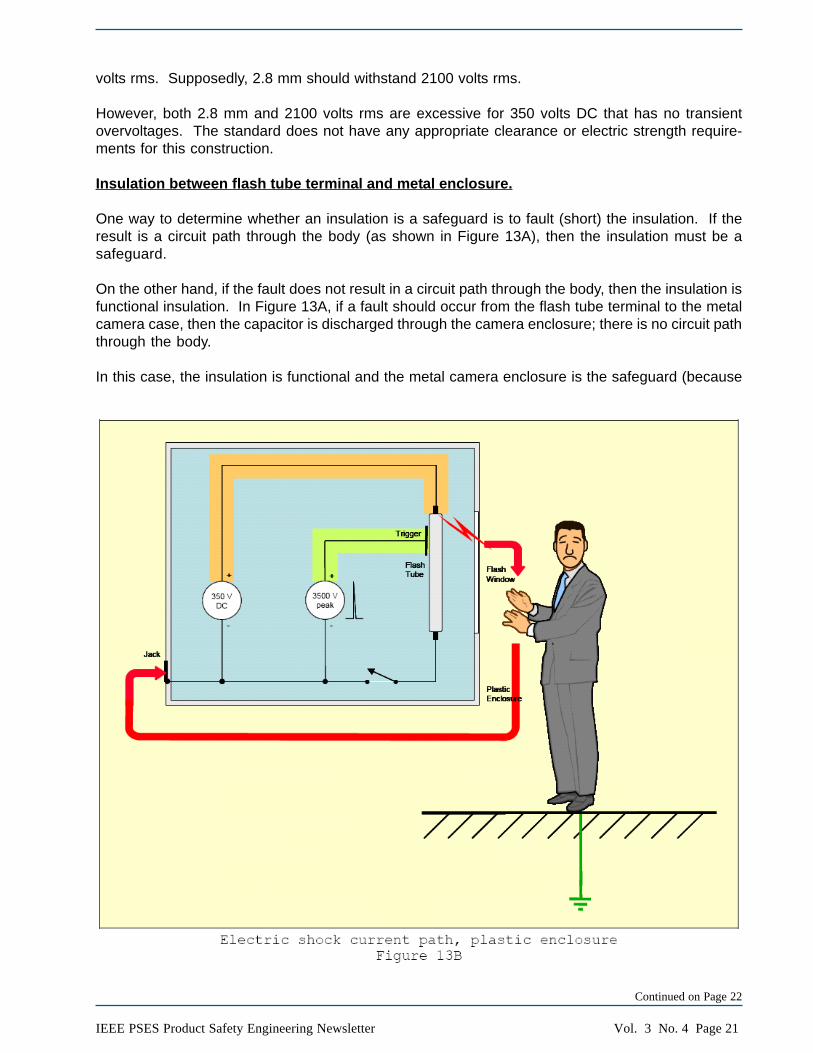
Insulation between flash tube terminal and metal enclosure.
One way to determine whether an insulation is a safeguard is to fault (short) the insulation. If theresult is a circuit path through the body (as shown in Figure 13A), then the insulation must be asafeguard.
On the other hand, if the fault does not result in a circuit path through the body, then the insulation isfunctional insulation. In Figure 13A, if a fault should occur from the flash tube terminal to the metalcamera case, then the capacitor is discharged through the camera enclosure; there is no circuit paththrough the body.
In this case, the insulation is functional and the metal camera enclosure is the safeguard (because
Continued on Page 22

Vol. 3 No. 4 Page 22 IEEE PSES Product Safety Engineering Newsletter
it returns the fault current to the capacitor). The camera enclosure must be capable of carrying thedischarge current for the duration of the discharge. This can be verified by a simple test of shortingthe 350 volts DC to the camera enclosure.
Safeguards – plastic enclosure.
Figure 13B illustrates the current path for an electric shock from the charged 200 µF capacitorconductors via fault between the flash tube terminal and through a seam in the plastic enclosure.Note that this scenario is the same as for a fault between the flash tube terminal and the flashwindow.
To prevent electric shock in this scenario, the requirements for the plastic enclosure are exactly thesame as for the flash tube window discussed for the metal enclosure. We need not repeat thisdiscussion.
Summary.
Now let’s review the CTL questions and decisions.
Question #1: Is an electrical enclosure (1.2.6.4) requires (sic) for Digital Cameras that contain a(Xenon tube) flash, if the flash energy storage capacitor is charged at hazardous voltage?
Decision #1: Yes, an electrical enclosure is required.
Our opinion #1: We have proved that, due to the charging of a 200 µF capacitor, hazardous voltageis generated. Therefore, an electrical enclosure is necessary. We agree with the decision.
Question #2: What protection class against electric shock should be defined?
Decision #2: A classification is according to 1.2.4 not necessary, but the construction has to providedouble or reinforced insulation between hazardous live parts and accessible parts. Marking toClass II is not required.
Our opinion #2: The camera is not Class I because it is not grounded. The camera is not Class IIbecause it does not require double insulation for a metal enclosure, but is Class II for aninsulating enclosure. The camera is not Class III because it has hazardous voltage. For thesolid insulation (plastic) parts of the enclosure, the construction requires double or reinforcedinsulation with respect to the hazardous voltage. We agree with the decision.
Question #3: Is an electric strength test between parts/circuits at hazardous voltage and SELVcircuits/conductive enclosure required (All these parts are commonly connected at one pointwithout insulation (secondary ground)?
Decision #3: An electric strength test is required.
Our opinion #3: We agree that an electric strength test is required between the hazardous voltageand the flash window together with accessible surfaces of a plastic camera enclosure. However,the standard does not specify a test voltage for DC secondary circuit construction that is notsubject to transient overvoltage. Moreover, clearance, creepage distance, and distance throughsolid insulation must comply with the standard. An electric strength test is not required betweenthe hazardous voltage and a metal enclosure. A fault test from hazardous voltage to the metal
Vol. 3 No. 4 Page 23IEEE PSES Product Safety Engineering Newsletter
enclosure should be conducted to verify that the discharge circuit can withstand the dischargecurrent. While we agree with the decision, the standard does not specify a suitable test voltage.
Explanatory note: If the equipment contains parts and circuits at hazardous voltage, which do mot(sic) meet the requirements of LCC or SELV, protection must be provided in form of an electricalenclosure with suitable mechanical strength.
Our opinion: We agree that the camera enclosure is an electrical enclosure and must have suitablemechanical strength.
*****If you have any comments or questions about this article, please send them to Richard Nute,[email protected].
If you have a question about safety, and would like to see the answer published here, please sendthe question to Richard Nute, [email protected]
References.
(1) http://www.iecee.org/ctl/CTL_decisions.htm
(2) For a more detailed explanation of flash lamp operation, see http://members.misty.com/don/samflash.html#strbpoo
(3) For more flash unit safety, see: http://members.misty.com/don/xesafe.html
(4) For more information on Paschen’s Law, see: http://home.earthlink.net/~jimlux/hv/paschen.htm
(5) IEC 60664-1, Edition 1, Annex A1, Table A1. Also, IEC 60664-1, Edition 2, Annex A, Table A.1.

Vol. 3 No. 4 Page 24 IEEE PSES Product Safety Engineering Newsletter
SAFETY CONSIDERATIONS FOR LIQUIDFILLED HEAT SINKS
BY: LAL BAHRA P. ENG.DELL INC.
Introduction
The basis for applying safeguard requirements to Information Technology Equipment (ITE) contain-ing liquids is the requirement in sub-clause 4.3.10 of IEC 60950-1, which states the following:
Equipment producing dust (e.g. paper dust) or using powders, liquids or gases shall be so constructed that nodangerous concentration of these materials can exist and that no hazard in the meaning of this standard iscreated by condensation, vaporization, leakage, spillage or corrosion during normal operation, storage, filling oremptying. In particular, Creepage distances and Clearances shall not be reduced below the requirements of2.10.
In addition, sub-clause 4.3.11 states:
Equipment that, in normal use, contains liquids or gases shall incorporate adequate safeguards against build-upof excessive pressure.
The above subclauses provide very general guidelines and do not completely specify the requiredsafeguards and safeguard requirements. We need to look into other standards which address equip-ment that use pressurized and non-pressurized liquid containment vessels and address compatibilityissues when plastic materials are used in conjunction with liquids.
Product sizes are continuously being reduced and integrated circuit (IC) chips are becoming morecompact containing more and more components. They are also going up in processing speeds.Products that try to keep up with new technology need more power and as a result, generate moreheat in the equipment. This heat must be moved out of the product. There are many different typesof systems available for cooling (moving heat out of the product). We are going to discuss mainly twotypes of liquid cooling systems here:
NOTE – This article does not discuss EMC, ROHS or acoustic considerations. These should be taken into account asapplicable.
Liquid Cooling Heat Pipes
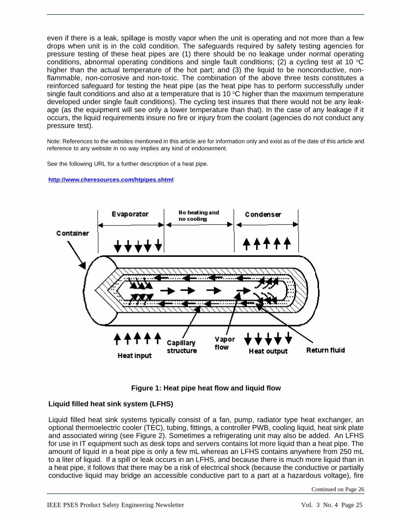
A heat pipe can quickly transfer heat from one point to another (see Figure 1). It works on theprinciple that if there is a difference in temperature at two ends of the heat pipe, the heat can betaken away from that point to the other end. It consists of a sealed metal hollow pipe (container)whose inner surface has a capillary wicking material (wick) and the cooling liquid. It transfers heat byevaporation and condensation cycle with the help of porous wicking material. When one end is hot,the liquid evaporates (that reduces the temperature of the hot part) and vapor travels to the other endwhere it condenses (releasing the heat). The wick provides the capillary action to bring the liquidback to the evaporator. These types of devices contain a very small amount of liquid that is mainlycontained in the wicking material. The working pressure inside the heat pipe is equal to the vaporpressure of the liquid (for example, the vapor pressure of Ammonia is 1554 kPa at 40 oC; and vaporpressure of water is 7.37 kPa at 40 oC). Vapor pressure is higher at high temperatures. Most com-monly used liquids are ammonia and water. The leakage of liquid is not of concern here because
Vol. 3 No. 4 Page 25IEEE PSES Product Safety Engineering Newsletter
even if there is a leak, spillage is mostly vapor when the unit is operating and not more than a fewdrops when unit is in the cold condition. The safeguards required by safety testing agencies forpressure testing of these heat pipes are (1) there should be no leakage under normal operatingconditions, abnormal operating conditions and single fault conditions; (2) a cycling test at 10 oChigher than the actual temperature of the hot part; and (3) the liquid to be nonconductive, non-flammable, non-corrosive and non-toxic. The combination of the above three tests constitutes areinforced safeguard for testing the heat pipe (as the heat pipe has to perform successfully undersingle fault conditions and also at a temperature that is 10 oC higher than the maximum temperaturedeveloped under single fault conditions). The cycling test insures that there would not be any leak-age (as the equipment will see only a lower temperature than that). In the case of any leakage if itoccurs, the liquid requirements insure no fire or injury from the coolant (agencies do not conduct anypressure test).
Note: References to the websites mentioned in this article are for information only and exist as of the date of this article andreference to any website in no way implies any kind of endorsement.
See the following URL for a further description of a heat pipe.
http://www.cheresources.com/htpipes.shtml
Figure 1: Heat pipe heat flow and liquid flow
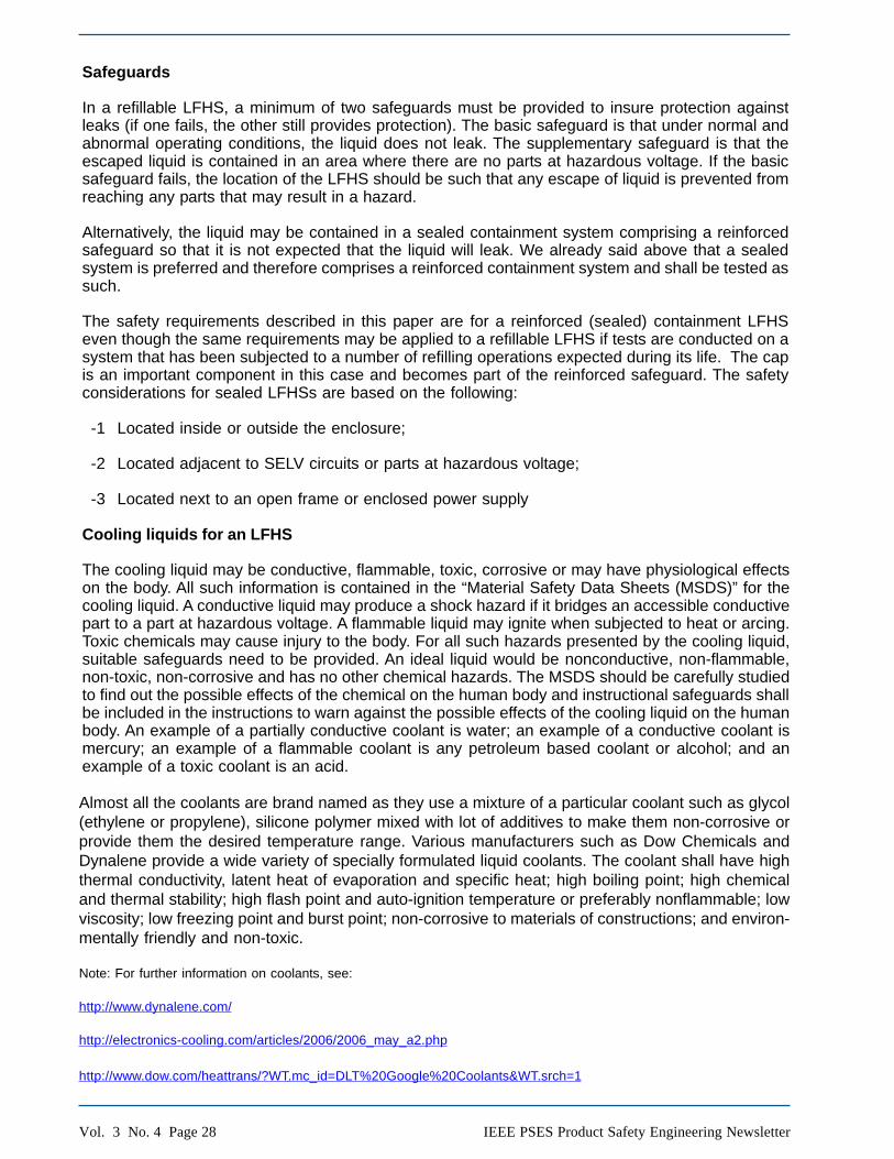
Liquid filled heat sink system (LFHS)
Liquid filled heat sink systems typically consist of a fan, pump, radiator type heat exchanger, anoptional thermoelectric cooler (TEC), tubing, fittings, a controller PWB, cooling liquid, heat sink plateand associated wiring (see Figure 2). Sometimes a refrigerating unit may also be added. An LFHSfor use in IT equipment such as desk tops and servers contains lot more liquid than a heat pipe. Theamount of liquid in a heat pipe is only a few mL whereas an LFHS contains anywhere from 250 mLto a liter of liquid. If a spill or leak occurs in an LFHS, and because there is much more liquid than ina heat pipe, it follows that there may be a risk of electrical shock (because the conductive or partiallyconductive liquid may bridge an accessible conductive part to a part at a hazardous voltage), fire
Continued on Page 26

Vol. 3 No. 4 Page 26 IEEE PSES Product Safety Engineering Newsletter
(the leaked flammable liquid may get hot and ignite) or chemical hazard (the liquid may be toxic)depending upon the location, flame properties and toxicity of the liquid.
There are two major types of LFHS systems available on the market, refillable and sealed typesystems.
A refillable system requires the user to replace the liquid at regular intervals. In doing so, there is apossibility of user error in (1) removing the old liquid from the LFHS; (2) cleaning; (3) refilling theliquid; and (4) restoring the equipment to its original condition. Errors in these activities may lead tospillages or leakages. Since the LFHS temperature and pressure both build up during the operationof the equipment (the temperature rises due to thermal energy dissipation and the hot liquid evapo-rates to generate higher pressure), there is a possibility of a leak which may result in possible haz-ards.
A sealed system is where a definite quantity of liquid cooling agent is sealed under vacuum toensure that the pressure inside the LFHS is at the vapor pressure of the liquid. The filling andsealing is done at the factory by the manufacturer. This results in a better LFHS that will not spill orleak as the manufacturing is conducted under tight quality control programs. In addition a pressuretest is conducted as a routine test to test for any leaks. A sealed system is a preferred system as thepossibility of a leak is greatly reduced.
Refillable and sealed LFHSs are used in desk top units or stationary equipment and in printers.Refillable LFHSs are not recommended for use in any portable equipment where orientation maychange for the reasons given previously (unless the product is tested in all such orientations after anumber of refilling cycles expected to occur during the life of the product). If the LFHS is of a sealedtype construction, then the system is orientation proof (this should not be a concern but a goodengineering practice is that the pump does not become the high point in the system).
Figure 2: Liquid filled sealed heat sink system Continued on Page 28

Vol. 3 No. 4 Page 27IEEE PSES Product Safety Engineering Newsletter
2004 / 2005 / 2006 / 2007 IEEE-PSE Symposium
CD Purchasing Information
SYMPOSIUM PAPERS ON CD:
The Product Safety Engineering Society continues to offer the 2004 IEEE PSES records forsale. The cost for the CD is $35 plus shipping and handling for IEEE members; $50 plus ship-ping and handling for non-IEEE members. At this time, check or money orders are the meansfor payment. Please provide the following information:
CDs to be shipped to- ( Please print or type.)
Name:__________________________________________
Mailing address::__________________________________________
__________________________________________
__________________________________________
__________________________________________
IEEE member number:_________________
Shipping and handling: $5 per CD
Payment: Check or money order.
Make Check or money order to: "IEEE Product Safety Society"
Quantity 2004:____ x $35 = _________ for IEEE membersQuantity 2004:____ x $50 = _________ for non-IEEE membersQuantity 2005:____ x $35 = _________ for IEEE membersQuantity 2005:____ x $50 = _________ for non-IEEE membersQuantity 2006:____ x $35 = _________ for IEEE membersQuantity 2006:____ x $50 = _________ for non-IEEE membersQuantity 2007:____ x $35 = _________ for IEEE membersQuantity 2007:____ x $50 = _________ for non-IEEE members
S&H: QTY_____ x $5 = _________
Total = _________Send payment to:
IEEE Product Safety Engineering Societyc/o Richard Georgerian, PSES Board of Directors7103 Sioux CourtLongmont, CO 80504U.S.A.
Depending on stock availability allow 2 to 3 weeks for delivery.
Vol. 3 No. 4 Page 28 IEEE PSES Product Safety Engineering Newsletter
Safeguards
In a refillable LFHS, a minimum of two safeguards must be provided to insure protection againstleaks (if one fails, the other still provides protection). The basic safeguard is that under normal andabnormal operating conditions, the liquid does not leak. The supplementary safeguard is that theescaped liquid is contained in an area where there are no parts at hazardous voltage. If the basicsafeguard fails, the location of the LFHS should be such that any escape of liquid is prevented fromreaching any parts that may result in a hazard.
Alternatively, the liquid may be contained in a sealed containment system comprising a reinforcedsafeguard so that it is not expected that the liquid will leak. We already said above that a sealedsystem is preferred and therefore comprises a reinforced containment system and shall be tested assuch.
The safety requirements described in this paper are for a reinforced (sealed) containment LFHSeven though the same requirements may be applied to a refillable LFHS if tests are conducted on asystem that has been subjected to a number of refilling operations expected during its life. The capis an important component in this case and becomes part of the reinforced safeguard. The safetyconsiderations for sealed LFHSs are based on the following:
-1 Located inside or outside the enclosure;
-2 Located adjacent to SELV circuits or parts at hazardous voltage;
-3 Located next to an open frame or enclosed power supply
Cooling liquids for an LFHS
The cooling liquid may be conductive, flammable, toxic, corrosive or may have physiological effectson the body. All such information is contained in the “Material Safety Data Sheets (MSDS)” for thecooling liquid. A conductive liquid may produce a shock hazard if it bridges an accessible conductivepart to a part at hazardous voltage. A flammable liquid may ignite when subjected to heat or arcing.Toxic chemicals may cause injury to the body. For all such hazards presented by the cooling liquid,suitable safeguards need to be provided. An ideal liquid would be nonconductive, non-flammable,non-toxic, non-corrosive and has no other chemical hazards. The MSDS should be carefully studiedto find out the possible effects of the chemical on the human body and instructional safeguards shallbe included in the instructions to warn against the possible effects of the cooling liquid on the humanbody. An example of a partially conductive coolant is water; an example of a conductive coolant ismercury; an example of a flammable coolant is any petroleum based coolant or alcohol; and anexample of a toxic coolant is an acid.
Almost all the coolants are brand named as they use a mixture of a particular coolant such as glycol(ethylene or propylene), silicone polymer mixed with lot of additives to make them non-corrosive orprovide them the desired temperature range. Various manufacturers such as Dow Chemicals andDynalene provide a wide variety of specially formulated liquid coolants. The coolant shall have highthermal conductivity, latent heat of evaporation and specific heat; high boiling point; high chemicaland thermal stability; high flash point and auto-ignition temperature or preferably nonflammable; lowviscosity; low freezing point and burst point; non-corrosive to materials of constructions; and environ-mentally friendly and non-toxic.
Note: For further information on coolants, see:
http://www.dynalene.com/
http://electronics-cooling.com/articles/2006/2006_may_a2.php
http://www.dow.com/heattrans/?WT.mc_id=DLT%20Google%20Coolants&WT.srch=1
Vol. 3 No. 4 Page 29IEEE PSES Product Safety Engineering Newsletter
Refillable and sealed LFHSs
Most commonly used LFHSs are sealed units made to last for the life of the equipment. While refill-able LFHSs require periodic maintenance, they may pose additional problems due to the use ofincorrect refilling liquid; the incorrect amount of liquid; liquid spillage during refilling; exposure of thebody to the liquid; somebody trying to smoke near a flammable liquid; etc.
Operation
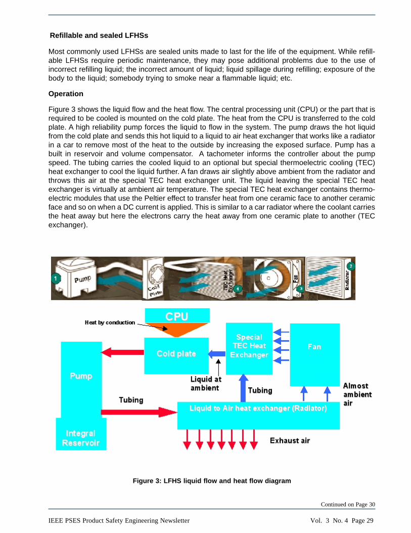
Figure 3 shows the liquid flow and the heat flow. The central processing unit (CPU) or the part that isrequired to be cooled is mounted on the cold plate. The heat from the CPU is transferred to the coldplate. A high reliability pump forces the liquid to flow in the system. The pump draws the hot liquidfrom the cold plate and sends this hot liquid to a liquid to air heat exchanger that works like a radiatorin a car to remove most of the heat to the outside by increasing the exposed surface. Pump has abuilt in reservoir and volume compensator. A tachometer informs the controller about the pumpspeed. The tubing carries the cooled liquid to an optional but special thermoelectric cooling (TEC)heat exchanger to cool the liquid further. A fan draws air slightly above ambient from the radiator andthrows this air at the special TEC heat exchanger unit. The liquid leaving the special TEC heatexchanger is virtually at ambient air temperature. The special TEC heat exchanger contains thermo-electric modules that use the Peltier effect to transfer heat from one ceramic face to another ceramicface and so on when a DC current is applied. This is similar to a car radiator where the coolant carriesthe heat away but here the electrons carry the heat away from one ceramic plate to another (TECexchanger).
Figure 3: LFHS liquid flow and heat flow diagram
Continued on Page 30

Vol. 3 No. 4 Page 30 IEEE PSES Product Safety Engineering Newsletter
The wider arrows show the liquid flow with red arrow carrying the heat in the direction of the arrow; and the blue arrow carrying the cold liquid in
the direction of the arrow. The thinner arrows indicate the air flow with red arrow carrying the hot air in the direction of the arrow and the blue arrow
carrying the cold air in the direction of the arrow.
Assumptions
Following assumptions are made (these assumptions apply to both sealed and refillable units exceptthe last dash paragraph that applies only to refillable LFHS):
- The tubing is a single-layered metal (copper) construction. If tubing is nonmetallic then theflammability requirements of the applicable standard need to be taken into account (even thoughinternal temperature of the tubing is same as the temperature of the cooling liquid, a flame dueto another source in the product may ignite the tubing from inside or outside). Both metallic andnonmetallic may qualify as a reinforced safeguard if they pass the required tests. In addition,the nonmetallic tubing must be able to pass tensile strength requirements after conditioningtests to simulate aging. Under high pressure, the tubing may tend to expand or elongate.
- The fittings are metal. If nonmetallic then the flammability requirements of the applicable stan-dard and creep resistance requirements need to be taken into account. These requirementsapply independently of if the tubing is metallic or nonmetallic.
- Working pressure is determined under normal operating conditions and abnormal operatingconditions. The hydrostatic test pressure is 5 times the working pressure under normal operat-ing conditions, abnormal operating conditions and construction (tubing, fitting, heat exchanger,any joints, etc.) must be suitable for this working pressure and also at a certain minimum tem-perature which is taken as to be not less than 85 oC. Higher temperatures under normal, abnor-mal or single fault conditions would dictate a measurement of working pressure at that tempera-ture.
- Working pressure is also determined under single fault conditions; the hydrostatic test pressureis three times the working pressure under single fault conditions.
- The fluid does not cause corrosion (corrosion may reduce the life of the LFHS) and is notflammable unless a reinforced containment is provided (e.g. corrosion resistant and nonflam-mable cooling liquid for example, propylene glycol). Corrosion may occur in a sealed systemalso as it may come from the outside (exposed parts of the radiator may get affected by corro-sion from outside and therefore, appropriately coated material must be used to make the partscorrosion resistant over the life of the product). Manufacturers of coolants add special additivesto make them corrosion resistant.
- The liquid is non toxic as proven by the MSDS for the fluid material unless a reinforced (sealed)containment is provided. Appropriate instructions for disposal at the end of life need to beprovided.
- The LFHS is used inside the enclosure of the equipment. If the LFHS is used outside theenclosure then additional safety criteria (protection against mechanical handling, impact, etc.)needs to be considered.
- For refillable LFHSs, instructional safeguards are provided for proper refilling of the coolingliquid; precautions to be taken; how to insure that the LFHS cap has been properly closed; etc.The working pressure at the operating temperature is much higher and the reinforced safe-guard must remain intact after the refilling operation is completed.
Vol. 3 No. 4 Page 31IEEE PSES Product Safety Engineering Newsletter
APPLICABLE STANDARDS (that need to be considered):
There was no single safety standard found that addressed the safety considerations for LFHSs. Thefollowing standards were consulted in whole or in part for the safety considerations for equipmentusing liquid filled heat sink systems.
- IEC/UL60950-1 (referred to further as 60950-1): Safety standard for IT equipment
- UL Subject 2178: Outline of Investigation for Marking and Coding Equipment: A part of thisstandard covers creep resistance of plastics and compatibility issues between a plastic mate-rial and a liquid and effect of liquids on tensile strength of plastic materials.
- UL 1995: Heating and cooling equipment: A part of this standard covers the evaluation ofcontainers under pressure.
- IEC 61010-1: Electrical Equipment for Measurement, Control, and Laboratory Use; Part 1:General Requirements: A part of this standard covers spillage of liquids from non-pressurizedcontainers
- IEC 60065: Audio/video apparatus: A part of this standard covers the vibration test
- Miscellaneous Standards (used for test methods only, see Test Program for details)
Safety Testing Agencies may utilize additional standards and test methods to address the completescope of potential hazards.
Possible hazards
This discussion only applies to a sealed LFHS. It can be applied to refillable systems after conduct-ing a number of refilling operations and conducting all the tests after such operations as explainedabove. The safeguard is the containment system that should prevent leakage. If there is no leakage,then we don’t care about the nature of the coolant except that the liquid shall not be corrosive to thematerial of the container (some liquids may corrode plastics also and therefore, compatibility of thematerials must be established before they are used). Ammonia was a popular coolant, but due toleakage and consequent injury in early refrigeration systems, ammonia now is seldom used even insealed systems. Likewise, chlorofluorocarbons were used in automobile air conditioners, but auto-mobile systems could be damaged and the coolant released into the atmosphere could result indamage to the ozone layer.
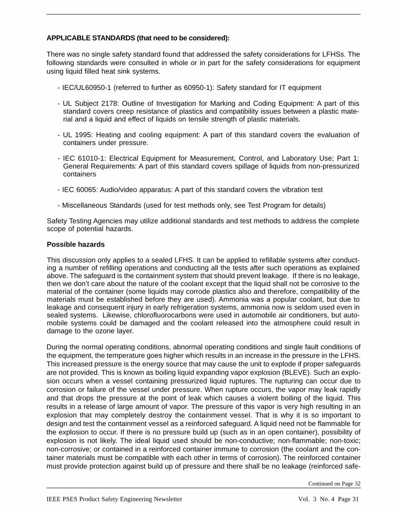
During the normal operating conditions, abnormal operating conditions and single fault conditions ofthe equipment, the temperature goes higher which results in an increase in the pressure in the LFHS.This increased pressure is the energy source that may cause the unit to explode if proper safeguardsare not provided. This is known as boiling liquid expanding vapor explosion (BLEVE). Such an explo-sion occurs when a vessel containing pressurized liquid ruptures. The rupturing can occur due tocorrosion or failure of the vessel under pressure. When rupture occurs, the vapor may leak rapidlyand that drops the pressure at the point of leak which causes a violent boiling of the liquid. Thisresults in a release of large amount of vapor. The pressure of this vapor is very high resulting in anexplosion that may completely destroy the containment vessel. That is why it is so important todesign and test the containment vessel as a reinforced safeguard. A liquid need not be flammable forthe explosion to occur. If there is no pressure build up (such as in an open container), possibility ofexplosion is not likely. The ideal liquid used should be non-conductive; non-flammable; non-toxic;non-corrosive; or contained in a reinforced container immune to corrosion (the coolant and the con-tainer materials must be compatible with each other in terms of corrosion). The reinforced containermust provide protection against build up of pressure and there shall be no leakage (reinforced safe-
Continued on Page 32
Vol. 3 No. 4 Page 32 IEEE PSES Product Safety Engineering Newsletter
guard). The container needs to be qualified against any leaks as the leak may not repeat in the sameplace if the LFHS is permitted to leak (if the container is qualified as a basic safeguard only andadditional supplementary safeguard is provided to contain the leaked material).
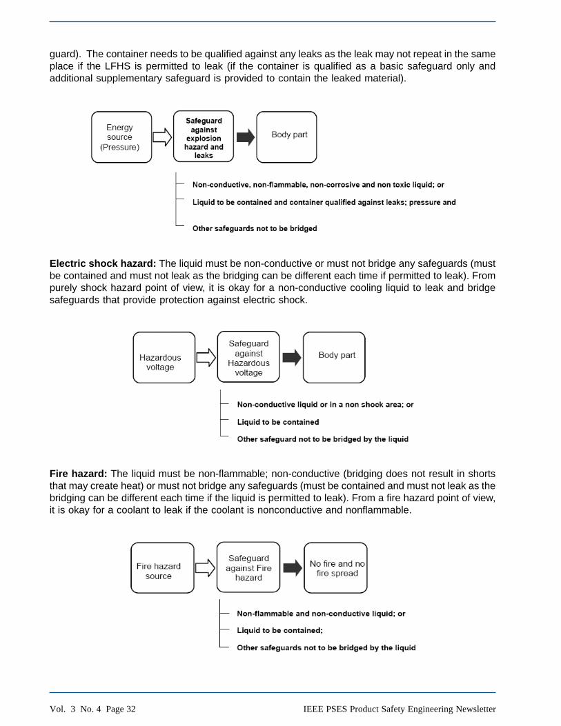
Electric shock hazard: The liquid must be non-conductive or must not bridge any safeguards (mustbe contained and must not leak as the bridging can be different each time if permitted to leak). Frompurely shock hazard point of view, it is okay for a non-conductive cooling liquid to leak and bridgesafeguards that provide protection against electric shock.
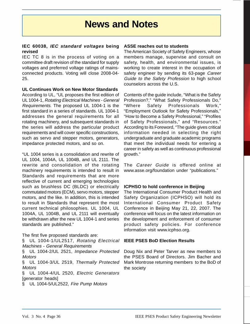
Fire hazard: The liquid must be non-flammable; non-conductive (bridging does not result in shortsthat may create heat) or must not bridge any safeguards (must be contained and must not leak as thebridging can be different each time if the liquid is permitted to leak). From a fire hazard point of view,it is okay for a coolant to leak if the coolant is nonconductive and nonflammable.

Vol. 3 No. 4 Page 33IEEE PSES Product Safety Engineering Newsletter
Mechanical hazard: The build up of pressure in the system must not present an explosion hazard(criteria for pressure testing is usually five times the working pressure under normal operating condi-tions or three times the working pressure under abnormal or single fault conditions whichever ishigher); the liquid must be non-conductive (conductive liquid may bridge electrical contact gaps thatprovide interlocked protection for doors or covers that provide safeguards against mechanical haz-ard) or must not bridge any safeguards (Must be contained and must not leak as the bridging can bedifferent each time if liquid is permitted to leak). The handling of mechanical parts by ordinary andskilled persons and any vibrations, etc. should not make the fittings loose. A vibration test needs tobe conducted to insure the fittings stay in place and do not result in any leakage.
Chemical hazard: The liquid must be non-toxic and non-corrosive or contained in a corrosion resis-tant container; (must be contained and must not leak as the bridging of other safeguards can bedifferent each time if the liquid is permitted to leak).
Conditions of acceptability
Safety Testing Agencies may add conditions of acceptability (C of A) when they qualify LFHS as acomponent. Such C of A must be carefully considered when designing and evaluating the final productcontaining the LFHS.
Instructional safeguards
The following instructional safeguards need to be considered:Continued on Page 34

Vol. 3 No. 4 Page 34 IEEE PSES Product Safety Engineering Newsletter
The liquid filled heat sink system is not user-serviceable;
For a refillable LFHS, instructions, precautions and inspections that are necessary for the user toconduct the refilling operation (including the proper securement of the cap) as applicable. Inaddition, a warning marking to not open the cap when hot shall be provided.
The liquid filled heat sink cooling system is not refillable or replaceable (as appropriate);
User should be cautious when removing/inserting accessory cards and drives to avoid damagingany part of the system (i.e. causing a leak in the tubing) - assumes user accessibility;
User should be made aware that the system has fluid and any sign of fluid leakage should resultin the user shutting down the system immediately and contacting manufacturer;
User should also be instructed on the hazards of eye or skin contact and proper cleaning meth-ods (e.g. avoid contact with skin, use dry clean cloth);
The user should be warned that any modification to the system could result in electric shock, fireor other hazards;
Any other instructional safeguard as applicable.
Agencies may require additional instructional safeguards.
Test Program
After a review of the standards mentioned under “Applicable standards” above, the following testslisted under “Possible Test Program” should be considered when evaluating an LFHS. All specifiedconditions of acceptability by the safety testing agencies need to be taken into account. There maybe a need for additional tests depending upon the location of the LFHS and its vicinity to other andtype of components and use of any other features such as a refrigerating unit.
Note: It is assumed that all construction and test criteria of the applicable end product standard apply. The test programmentioned here only includes those end product tests that would be affected by the liquid filled heat sink system and doesnot represent a full product investigation.
Other possible considerations
Manufacturer may consider conducting the following additional tests for a sealed LFHS:
Coolant: Normally, for a reinforced safeguard in a sealed system, we do not expect any leakage, soone would expect that any coolant may be used. In practice, due to unforeseeable misuse or otherfactors, there is always a possibility of a leak (that is the biggest fear of a designer). Due to thesereasons and concerns for safety of workers during production (such as filling the unit and sealing)and disposal concerns desire that a nontoxic, nonflammable, non-corrosive and nonconductive liq-uid should be used. Safety certification agencies may impose their own additional instructional safe-guards based on the nature of the chemical used (see Instructional safeguards).
Life cycle test: This shall be conducted to simulate the expected life duration and at the end of thistesting the LFHS must not fail in a way to cause damage to safeguards especially any leaks orcorrosion (especially of the heat exchanger as the material is thinner in the heat exchanger area).Non-corrosive liquids reduce this possibility and lengthen the life of the LFHS.
Burst pressure test: The hydrostatic test as given below in the table should be continued beyondthe maximum pressure required for the hydrostatic pressure test to know the pressure at which a

Vol. 3 No. 4 Page 35IEEE PSES Product Safety Engineering Newsletter
leak occurs or the LFHS bursts open and insure that there is a sufficient margin from the maximumpressure required for the hydrostatic pressure test. The burst pressure should be about 15 to 20times higher than the working pressure. That provides sufficient margin to put a safe product on themarket.
Summary: A sealed LFHS shall be designed and tested to insure that under normal operating,abnormal operating and single fault conditions the LFHS does not become a safety hazard. Thecontainment vessel should be designed and tested as a reinforced safeguard as a protection againstexcessive pressure that develops due to the hot liquid in the LFHS. Any leak in the LFHS may resultin a hazardous situation and shall be avoided. The ideal liquid preferably should be non-flammable,non-toxic, non-corrosive and non-conductive. User should be provided with appropriate instructionalsafeguards in order to avoid any hazard that may result from the use of LFHS in the equipment.
Conclusion: The sealed LFHS is a preferred cooling system when compared to a refillablesystem and when designed and tested properly offers a better protection for the equipment inwhich it is used over the lifetime of the product.
Acknowledgement: The author wants to thank all of the Dell staff and others who provided commentsespecially Rich Nute who encouraged me to add appropriate rational and explanation of various safetyconsiderations and was patient enough to provide comments to continuously make this a better article.
Vol. 3 No. 4 Page 36 IEEE PSES Product Safety Engineering Newsletter
News and Notes
IEC 60038, IEC standard voltages beingrevisedIEC TC 8 is in the process of voting on acommittee draft revision of the standard for supplyvoltages and preferred voltage ratings of mains-connected products. Voting will close 2008-04-25.
UL Continues Work on New Motor StandardsAccording to UL, “UL proposes the first edition ofUL 1004-1, Rotating Electrical Machines - GeneralRequirements. The proposed UL 1004-1 is thefirst standard in a series of standards. UL 1004-1addresses the general requirements for allrotating machinery, and subsequent standards inthe series will address the particular productrequirements and will cover specific constructions,such as servo and stepper motors, generators,impedance protected motors, and so on.
“UL 1004 series is a consolidation and rewrite ofUL 1004, 1004A, UL 1004B, and UL 2111. Therewrite and consolidation of the rotatingmachinery requirements is intended to result inStandards and requirements that are morereflective of current and emerging technologiessuch as brushless DC (BLDC) or electricallycommutated motors (ECM), servo motors, steppermotors, and the like. In addition, this is intendedto result in Standards that represent the mostcurrent technical philosophies. UL 1004, UL1004A, UL 1004B, and UL 2111 will eventuallybe withdrawn after the new UL 1004-1 and seriesstandards are published.”
The first five proposed standards are:§ UL 1004-1/UL2517, Rotating ElectricalMachines - General Requirements§ UL 1004-2/UL 2521, Impedance ProtectedMotors§ UL 1004-3/UL 2519, Thermally ProtectedMotors§ UL 1004-4/UL 2520, Electric Generators[generator heads]§ UL 1004-5/UL2522, Fire Pump Motors
ASSE reaches out to studentsThe American Society of Safety Engineers, whosemembers manage, supervise and consult onsafety, health, and environmental issues, isworking to create interest in the occupation ofsafety engineer by sending its 63-page CareerGuide to the Safety Profession to high schoolcounselors across the U.S.
Contents of the guide include, “What is the SafetyProfession?,” “What Safety Professionals Do,”“Where Safety Professionals Work,”“Employment Outlook for Safety Professionals,”“How to Become a Safety Professional,” “Profilesof Safety Professionals,” and “Resources.”According to its Foreword, “The guide gives criticalinformation needed in selecting the rightundergraduate and graduate academic programsthat meet the individual needs for entering acareer in safety as well as continuous professionalgrowth.”
The Career Guide is offered online atwww.asse.org/foundation under “publications.”
ICPHSO to hold conference in BeijingThe International Consumer Product Health andSafety Organization (ICPHSO) will hold itsInternational Consumer Product SafetyConference in Beijing May 21, 22, 2007. Theconference will focus on the latest information onthe development and enforcement of consumerproduct safety policies. For conferenceinformation visit www.icphso.org.
IEEE PSES BoD Election Results
Doug Nix and Peter Tarver as new members tothe PSES Board of Directors. Jim Bacher andMark Montrose returning members to the BoD ofthe society
07-PIM-0069d_IPEL.indd 1 6/6/07 11:46:44 AM

Vol. 3 No. 4 Page 37IEEE PSES Product Safety Engineering Newsletter
From Imagination to Market
IEEE Power & Energy LibraryAuthoritative Information for Innovative Organizations
Affordable access to the leading journals and cutting-edge conferences used by today’s most innovative power and energy organizations.
Focused, effi cient searching and browsing of power- specifi c documents
Over 1.5 million documents – including 75,000 specifi cally in power and energy technologies
INSPEC® bibliographic records for all publications Online fi ling cabinet for rapid collaboration Top cited journals in the fi eld
Free Trial!Experience IEEE – request a trial for your company.
www.ieee.org/powerlibrary
IEEE Information Driving Innovation
“The IEEE Power & Energy Library will help acceleratemy organization’s product development work.”
– John Estey, President & CEO, S&C Electric Company
07-PIM-0069d_IPEL.indd 1 6/6/07 11:46:44 AM

Vol. 3 No. 4 Page 38 IEEE PSES Product Safety Engineering Newsletter
The Product Safety Engineering Newsletter is published quarterly during the lastmonth of each calendar quarter. The following deadlines are necessary in order tomeet that schedule.
Closing dates for submitted articles:
1Q issue: February 12Q issue: May 13Q issue: August 14Q issue: November 1
Closing dates for news items:
1Q issue: February 152Q issue: May 153Q issue: August 154Q issue: November 15
Closing dates for advertising:
1Q issue: February 152Q issue: May 153Q issue: August 154Q issue: November 15
Booked your trip to the 2008 Symposium onCompliance Engineering yet?

Vol. 3 No. 4 Page 39IEEE PSES Product Safety Engineering Newsletter
Institutional Listings
We invite applications for Institutional Listings from firms interested in the product safetyfield. An Institutional Listing recognizes contributions to support publication of the IEEE Prod-uct Safety Engineering Newsletter. To place ad with us, please see :
http://www.ieee.org/ieeemediaClick here to go to the IEEE PSES advertising pdf
The Safety Link is the web’s most comprehensive col-lection of electrical product safety and standards re-sources. Founded in 1995; nearly a million visitors can’tbe wrong. Watch for the new and improved Safety Linkat: http://www.safetylink.com
Tthe Product Safety Engineering Society will accept advertisements for employment andplace looking for work ads on our web page. Please contact Dan Roman for details [email protected] .

Vol. 3 No. 4 Page 40 IEEE PSES Product Safety Engineering Newsletter
The
ProductSafetyEngineeringNewsletter
Gary WeidnerGW Technical Services Inc.2175 Clarke DriveDubuque, IA 52001-4125
CHANGE SERVICE REQUESTED
Related Documents