The Monitoring of Circumferential Fatigue Cracking of Furnace Tubes in Supercritical Boilers B.J. Robbins and D.M. Farrell Rowan Technologies Ltd 216 Church Road, Urmston, Manchester, UK. Tel: (44) 161 748 3644, E-mail: [email protected] J. Stallings and S. Cardoso Electric Power Research Institute 3420 Hillview Avenue, Palo Alto, CA, USA 1. Abstract Rowan Technologies has used potential drop techniques for many years to monitor corrosion/erosion of power plant boiler tube fireside surfaces. More recently, the techniques have been refined and applied to the monitoring of fireside circumferential cracking of furnace wall tubes in supercritical boilers, as part of an Electrical Power Research Institute (EPRI) funded project. Trials of simulated circumferential crack growth have shown that changes in measured signals are small but quantifiable under laboratory conditions. Following these successful laboratory trials, monitoring is currently underway using large-scale systems on two 800 MW supercritical boilers in the US. The monitoring systems are not only designed to detect crack propagation, but also to monitor and quantify the thermal characteristics of the tube walls, i.e. thermal instability and excessive temperatures, that are considered to be major factors contributing to tube cracking. This paper provides an overview of the measurement techniques employed, together with results from the laboratory and on-site projects to date. The circumstances and possible root causes of circumferential crack growth are discussed in detail. Understanding the root causes of the circumferential cracking is very much a goal of this particular project, so that appropriate action can be taken to minimise it. 2. Introduction Maintaining the basic fabric of boilers, which for large power generation units essentially comprises hundreds of miles of tubing, is a fundamental issue for boiler operators. Since the early 1990s, Rowan Technologies has been developing electrical resistance techniques to monitor the fireside integrity of boiler tube walls. Damage to the fireside tube surfaces, either from corrosion or cracking, can be a principle cause of premature tube failure and may result in unscheduled boiler shut downs for repair – a very costly undertaking. Early work at Rowan Technologies focussed on the use of intrusive air-cooled probes to simulate and monitor fireside tube wall corrosion at point locations 1 . In the late 1990s, the company adapted this technology to directly monitor the fireside corrosion rates of the boiler tubes themselves. This was achieved not simply at point locations, as with intrusive probes, but over large areas of boiler tube membrane wall, using arrays of electrodes welded to the external (cold-side) tube wall surfaces. By ‘scanning’ these sensors in sequence, complete two-dimensional maps are produced of real-time corrosion rates over large areas of wall 2 . The longest serving system, commissioned at Drax Power station (UK) in 2001, covers some 200m 2 of more vulnerable areas of membrane wall. These systems not only monitor tube wall integrity, but also provide real time mapping of the wall’s thermal performance in terms of heat flux and fireside tube temperatures.

Welcome message from author
This document is posted to help you gain knowledge. Please leave a comment to let me know what you think about it! Share it to your friends and learn new things together.
Transcript
The Monitoring of Circumferential Fatigue Cracking of Furnace Tubes in
Supercritical Boilers
B.J. Robbins and D.M. Farrell
Rowan Technologies Ltd
216 Church Road, Urmston, Manchester, UK.
Tel: (44) 161 748 3644, E-mail: [email protected]
J. Stallings and S. Cardoso
Electric Power Research Institute
3420 Hillview Avenue, Palo Alto, CA, USA
1. Abstract Rowan Technologies has used potential drop techniques for many years to monitor corrosion/erosion
of power plant boiler tube fireside surfaces. More recently, the techniques have been refined and
applied to the monitoring of fireside circumferential cracking of furnace wall tubes in supercritical
boilers, as part of an Electrical Power Research Institute (EPRI) funded project.
Trials of simulated circumferential crack growth have shown that changes in measured signals are
small but quantifiable under laboratory conditions. Following these successful laboratory trials,
monitoring is currently underway using large-scale systems on two 800 MW supercritical boilers in
the US. The monitoring systems are not only designed to detect crack propagation, but also to
monitor and quantify the thermal characteristics of the tube walls, i.e. thermal instability and
excessive temperatures, that are considered to be major factors contributing to tube cracking.
This paper provides an overview of the measurement techniques employed, together with results
from the laboratory and on-site projects to date. The circumstances and possible root causes of
circumferential crack growth are discussed in detail. Understanding the root causes of the
circumferential cracking is very much a goal of this particular project, so that appropriate action can
be taken to minimise it.
2. Introduction
Maintaining the basic fabric of boilers, which for large power generation units essentially comprises
hundreds of miles of tubing, is a fundamental issue for boiler operators. Since the early 1990s,
Rowan Technologies has been developing electrical resistance techniques to monitor the fireside
integrity of boiler tube walls. Damage to the fireside tube surfaces, either from corrosion or cracking,
can be a principle cause of premature tube failure and may result in unscheduled boiler shut downs
for repair – a very costly undertaking.
Early work at Rowan Technologies focussed on the use of intrusive air-cooled probes to simulate and
monitor fireside tube wall corrosion at point locations1. In the late 1990s, the company adapted this
technology to directly monitor the fireside corrosion rates of the boiler tubes themselves. This was
achieved not simply at point locations, as with intrusive probes, but over large areas of boiler tube
membrane wall, using arrays of electrodes welded to the external (cold-side) tube wall surfaces. By
‘scanning’ these sensors in sequence, complete two-dimensional maps are produced of real-time
corrosion rates over large areas of wall2. The longest serving system, commissioned at Drax Power
station (UK) in 2001, covers some 200m2 of more vulnerable areas of membrane wall. These systems
not only monitor tube wall integrity, but also provide real time mapping of the wall’s thermal performance in terms of heat flux and fireside tube temperatures.
2
More recently, EPRI (the US Electrical Power Research Institute) has been coordinating a project,
principally focussing on a supercritical boiler at Brunner Island power plant, Pennsylvania, that
applies the scanner technology to the more challenging task of monitoring fireside circumferential
crack growth on the membrane tube walls3. To help understand the root causes of this cracking, the
scanner systems also provide a valuable insight into the thermal behaviour of tube walls in areas
where cracking has been a major problem.
3. Circumferential Tube Wall Cracking in Supercritical Boilers
Supercritical boilers are high-efficiency power generation units. To help achieve greater efficiencies
than subcritical units, higher boiler tube water pressures are used. At supercritical pressures
(>3200psi), boiling ceases to occur. Water pressures subsequently drop below supercritical values in
the high pressure turbines.
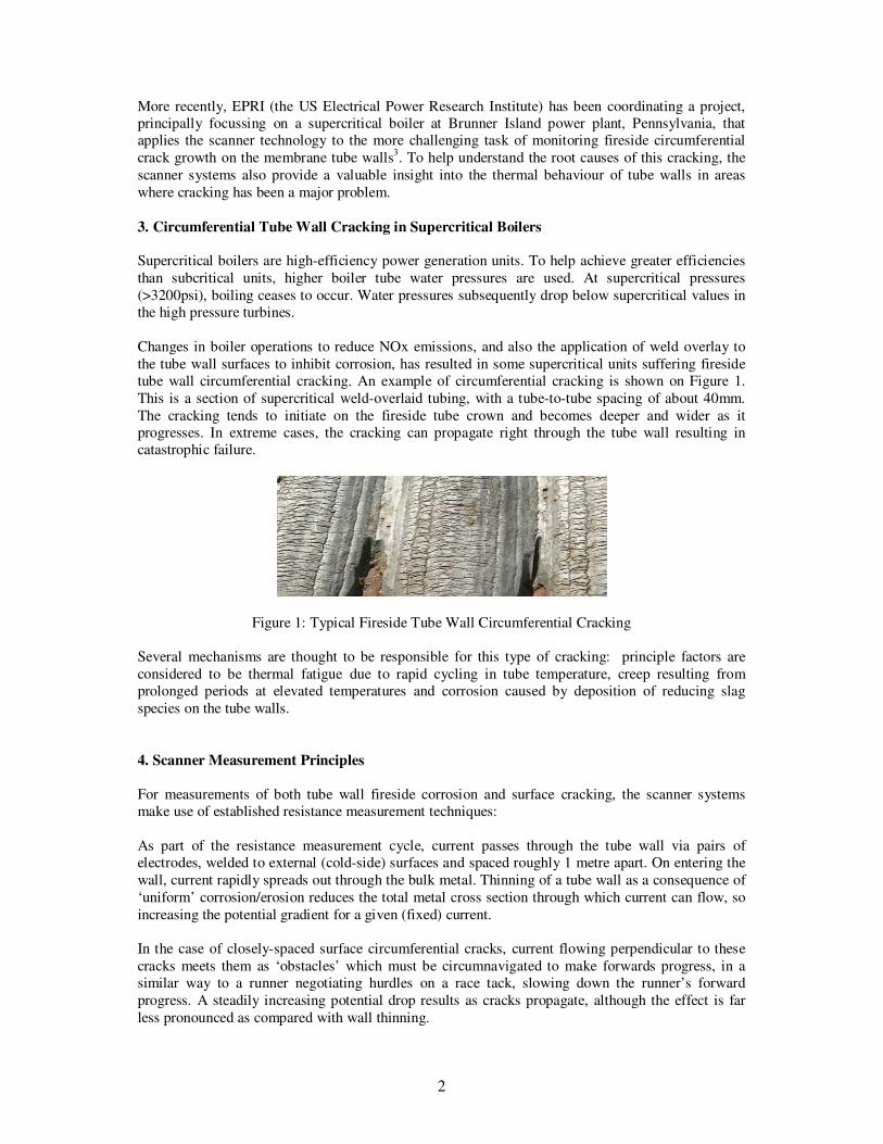
Changes in boiler operations to reduce NOx emissions, and also the application of weld overlay to
the tube wall surfaces to inhibit corrosion, has resulted in some supercritical units suffering fireside
tube wall circumferential cracking. An example of circumferential cracking is shown on Figure 1.
This is a section of supercritical weld-overlaid tubing, with a tube-to-tube spacing of about 40mm.
The cracking tends to initiate on the fireside tube crown and becomes deeper and wider as it
progresses. In extreme cases, the cracking can propagate right through the tube wall resulting in
catastrophic failure.
Figure 1: Typical Fireside Tube Wall Circumferential Cracking
Several mechanisms are thought to be responsible for this type of cracking: principle factors are
considered to be thermal fatigue due to rapid cycling in tube temperature, creep resulting from
prolonged periods at elevated temperatures and corrosion caused by deposition of reducing slag
species on the tube walls.
4. Scanner Measurement Principles
For measurements of both tube wall fireside corrosion and surface cracking, the scanner systems
make use of established resistance measurement techniques:
As part of the resistance measurement cycle, current passes through the tube wall via pairs of
electrodes, welded to external (cold-side) surfaces and spaced roughly 1 metre apart. On entering the
wall, current rapidly spreads out through the bulk metal. Thinning of a tube wall as a consequence of
‘uniform’ corrosion/erosion reduces the total metal cross section through which current can flow, so
increasing the potential gradient for a given (fixed) current.
In the case of closely-spaced surface circumferential cracks, current flowing perpendicular to these
cracks meets them as ‘obstacles’ which must be circumnavigated to make forwards progress, in a
similar way to a runner negotiating hurdles on a race tack, slowing down the runner’s forward
progress. A steadily increasing potential drop results as cracks propagate, although the effect is far
less pronounced as compared with wall thinning.
3
As resistance measurements are also heavily dependent on bulk metal temperature, the systems
simultaneously measure resistance and temperature and compensate for any temperature variations.
5. Circumferential Cracking – Laboratory Studies
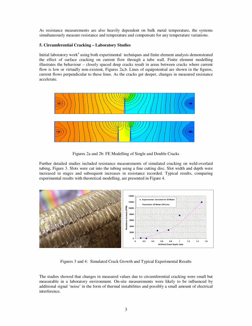
Initial laboratory work4 using both experimental techniques and finite element analysis demonstrated
the effect of surface cracking on current flow through a tube wall. Finite element modelling
illustrates the behaviour – closely spaced deep cracks result in areas between cracks where current
flow is low or virtually non-existent, Figures 2a,b. Lines of equipotential are shown in the figures,
current flows perpendicular to these lines. As the cracks get deeper, changes in measured resistance
accelerate.
Figures 2a and 2b: FE Modelling of Single and Double Cracks
Further detailed studies included resistance measurements of simulated cracking on weld-overlaid
tubing, Figure 3. Slots were cut into the tubing using a fine cutting disc. Slot width and depth were
increased in stages and subsequent increases in resistance recorded. Typical results, comparing
experimental results with theoretical modelling, are presented in Figure 4.
Figures 3 and 4: Simulated Crack Growth and Typical Experimental Results
The studies showed that changes in measured values due to circumferential cracking were small but
measurable in a laboratory environment. On-site measurements were likely to be influenced by
additional signal ‘noise’ in the form of thermal instabilities and possibly a small amount of electrical
interference.
0
2000
4000
6000
8000
10000
12000
14000
0 0.2 0.4 0.6 0.8 1 1.2 1.4 1.6
Artificial Crack Depth (mm)
Re
sis
tan
ce
In
cre
as
e (
PP
M)
Experimental: Corrected for 2D Model
Theoretical: 2D Model (Off-Line)
4
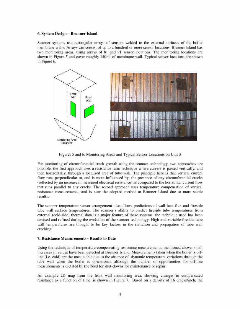
6. System Design – Brunner Island
Scanner systems use rectangular arrays of sensors welded to the external surfaces of the boiler
membrane walls. Arrays can consist of up to a hundred or more sensor locations. Brunner Island has
two monitoring areas, using arrays of 81 and 91 sensor locations. The monitoring locations are
shown in Figure 5 and cover roughly 140m2 of membrane wall. Typical sensor locations are shown
in Figure 6.
Figures 5 and 6: Monitoring Areas and Typical Sensor Locations on Unit 3
For monitoring of circumferential crack growth using the scanner technology, two approaches are
possible: the first approach uses a resistance ratio technique where current is passed vertically, and
then horizontally, through a localised area of tube wall. The principle here is that vertical current
flow runs perpendicular to, and is more influenced by, the presence of any circumferential cracks
(reflected by an increase in measured electrical resistance) as compared to the horizontal current flow
that runs parallel to any cracks. The second approach uses temperature compensation of vertical
resistance measurements, and is now the adopted method at Brunner Island due to more stable
results.
The scanner temperature sensor arrangement also allows predictions of wall heat flux and fireside
tube wall surface temperatures. The scanner’s ability to predict fireside tube temperatures from
external (cold-side) thermal data is a major feature of these systems: the technique used has been
devised and refined during the evolution of the scanner technology. High and variable fireside tube
wall temperatures are thought to be key factors in the initiation and propagation of tube wall
cracking.
7. Resistance Measurements - Results to Date
Using the technique of temperature-compensating resistance measurements, mentioned above, small
increases in values have been detected at Brunner Island. Measurements taken when the boiler is off-
line (i.e. cold) are the most stable due to the absence of dynamic temperature variations through the
tube wall when the boiler is operational, although the number of opportunities for off-line
measurements is dictated by the need for shut-downs for maintenance or repair.
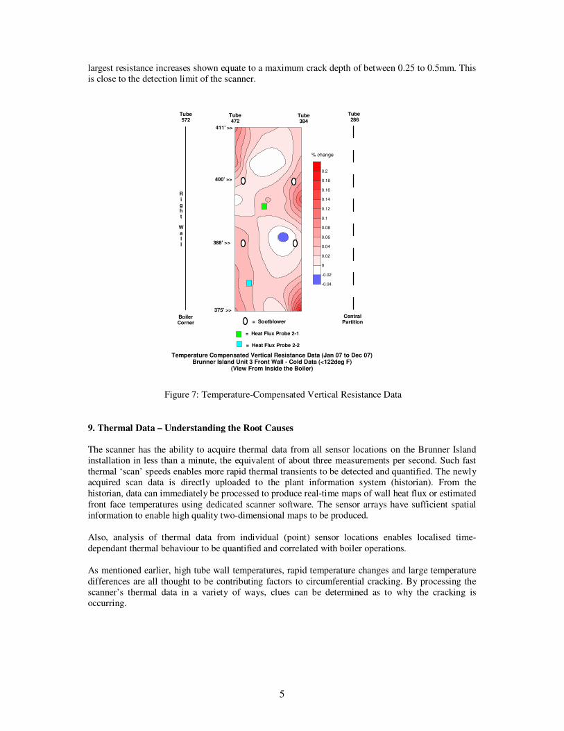
An example 2D map from the front wall monitoring area, showing changes in compensated
resistance as a function of time, is shown in Figure 7. Based on a density of 16 cracks/inch, the
5
largest resistance increases shown equate to a maximum crack depth of between 0.25 to 0.5mm. This
is close to the detection limit of the scanner.
Figure 7: Temperature-Compensated Vertical Resistance Data
9. Thermal Data – Understanding the Root Causes
The scanner has the ability to acquire thermal data from all sensor locations on the Brunner Island
installation in less than a minute, the equivalent of about three measurements per second. Such fast
thermal ‘scan’ speeds enables more rapid thermal transients to be detected and quantified. The newly
acquired scan data is directly uploaded to the plant information system (historian). From the
historian, data can immediately be processed to produce real-time maps of wall heat flux or estimated
front face temperatures using dedicated scanner software. The sensor arrays have sufficient spatial
information to enable high quality two-dimensional maps to be produced.
Also, analysis of thermal data from individual (point) sensor locations enables localised time-
dependant thermal behaviour to be quantified and correlated with boiler operations.
As mentioned earlier, high tube wall temperatures, rapid temperature changes and large temperature
differences are all thought to be contributing factors to circumferential cracking. By processing the
scanner’s thermal data in a variety of ways, clues can be determined as to why the cracking is
occurring.
Right
Wall
CentralPartition
411' >>
375' >>
Temperature Compensated Vertical Resistance Data (Jan 07 to Dec 07)Brunner Island Unit 3 Front Wall - Cold Data (<122deg F)
(View From Inside the Boiler)
Tube572
Tube 286
Tube 472
Tube384
= Sootblower
400' >>
388' >>
BoilerCorner
= Heat Flux Probe 2-1
= Heat Flux Probe 2-2
% change
-0.04
-0.02
0
0.02
0.04
0.06
0.08
0.1
0.12
0.14
0.16
0.18
0.2
6
10. Elevated Tube Wall Temperatures
At elevated tube wall temperatures, the tube’s yield strength is reduced and so ‘excessive’
temperatures that might compromise tube integrity are undesirable. Brunner Island has chosen to
apply weld overlay to much of the tube walls to inhibit corrosion, but the resulting wall thickening will tend to increase fireside surface temperatures. The actual process of applying weld overlay also
results in additional residual stresses within the tube walls that may encourage surface cracking or
crack propagation.
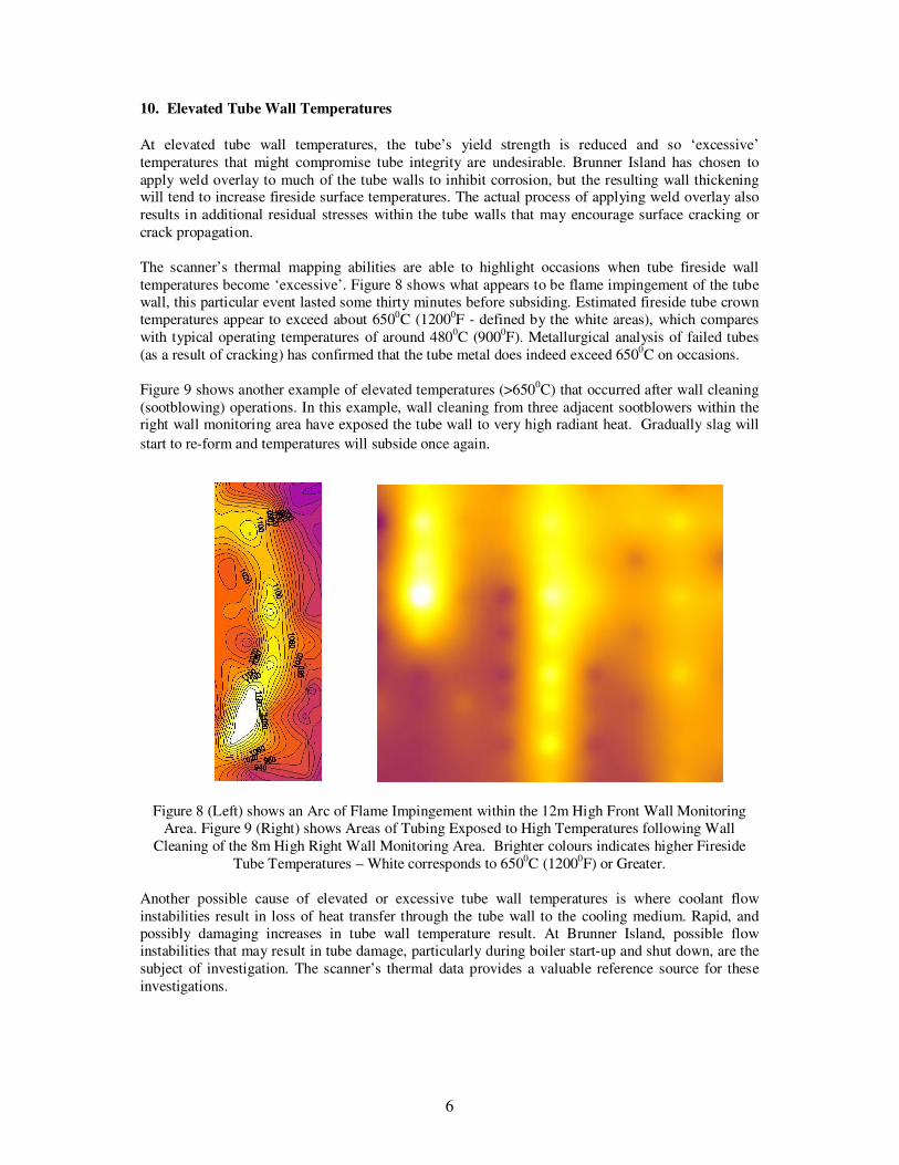
The scanner’s thermal mapping abilities are able to highlight occasions when tube fireside wall
temperatures become ‘excessive’. Figure 8 shows what appears to be flame impingement of the tube
wall, this particular event lasted some thirty minutes before subsiding. Estimated fireside tube crown
temperatures appear to exceed about 6500C (12000F - defined by the white areas), which compares
with typical operating temperatures of around 4800C (900
0F). Metallurgical analysis of failed tubes
(as a result of cracking) has confirmed that the tube metal does indeed exceed 6500C on occasions.
Figure 9 shows another example of elevated temperatures (>6500C) that occurred after wall cleaning
(sootblowing) operations. In this example, wall cleaning from three adjacent sootblowers within the right wall monitoring area have exposed the tube wall to very high radiant heat. Gradually slag will
start to re-form and temperatures will subside once again.
Figure 8 (Left) shows an Arc of Flame Impingement within the 12m High Front Wall Monitoring
Area. Figure 9 (Right) shows Areas of Tubing Exposed to High Temperatures following Wall
Cleaning of the 8m High Right Wall Monitoring Area. Brighter colours indicates higher Fireside
Tube Temperatures – White corresponds to 6500C (1200
0F) or Greater.
Another possible cause of elevated or excessive tube wall temperatures is where coolant flow
instabilities result in loss of heat transfer through the tube wall to the cooling medium. Rapid, and
possibly damaging increases in tube wall temperature result. At Brunner Island, possible flow
instabilities that may result in tube damage, particularly during boiler start-up and shut down, are the
subject of investigation. The scanner’s thermal data provides a valuable reference source for these
investigations.
7
11. Temperature Dynamics
Rapid temperature fluctuations and large temperature gradients between adjacent parts of the tube
wall results in areas of differing expansion, so inducing considerable stresses and contributing to
stress fatigue. These cyclic, cumulative effects on the tube metal, combined with elevated tube
surface temperatures, may ultimately result in the formation of microscopic circumferential cracks. It
is thought that the influence of corrosive species within the surface slag and continued stress cycling
gradually enlarge these cracks.
Thermal data from the Brunner Island scanner has highlighted both rapid temperature fluctuations
together with highly localised (spatial) temperature differences that can result from wall cleaning,
natural slag shedding, flame impingement etc. In the case of natural slag shedding, localised slag falls
can expose some tubes to high radiant heat whilst adjacent tubing remains covered by slag and are
considerably ‘cooler’. The central column of brighter temperatures of Figure 8 is one such localised
slag fall initiated by wall cleaning. The hotter, exposed tubing will want to expand whilst the cooler
tubing will not; large tube-to-tube wall stresses may result. Research has shown that large tube-to-
tube temperature differences can result in circumferential cracking5.
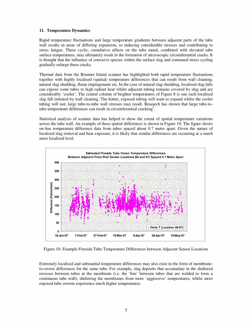
Statistical analysis of scanner data has helped to show the extent of spatial temperature variations
across the tube wall. An example of these spatial differences is shown in Figure 10. The figure shows
on-line temperature difference data from tubes spaced about 0.7 metre apart. Given the nature of
localised slag removal and heat exposure, it is likely that similar differences are occurring at a much
more localised level.
Figure 10: Example Fireside Tube Temperature Differences between Adjacent Sensor Locations
Extremely localised and substantial temperature differences may also exist in the form of membrane-
to-crown differences for the same tube. For example, slag deposits that accumulate in the sheltered
recesses between tubes at the membrane (i.e. the ‘fins’ between tubes that are welded to form a
continuous tube wall), sheltering the membranes from more ‘aggressive’ temperatures, whilst more
exposed tube crowns experience much higher temperatures.
Estimated Fireside Tube Crown Temperature Differences
Between Adjacent Front Wall Sensor Locations (66 and 67) Spaced 0.7 Metre Apart
0
50
100
150
200
250
300
350
400
18-Jan-07 7-Feb-07 27-Feb-07 19-Mar-07 8-Apr-07 28-Apr-07 18-May-07
Dif
fere
nce (
Fah
ren
heit
)
Delta T (Location 66-67)
8
Independent modelling of possible damage mechanisms that might result in tube wall cracking has
shown that some of the characteristics of the thermal behaviour of the tube walls at Brunner Island
are indeed capable of initiating cracking.
10. Discussion and Conclusions
The scanner technology has a proven record of monitoring boiler wall fireside corrosion using
electrical resistance techniques. Work is still on-going to prove/demonstrate the technique’s viability
in monitoring circumferential cracking of fireside boiler tube walls. Changes in measured resistance
values as a consequence of surface cracking are considerably smaller than those from surface
thinning corrosion. The fundamental physics shows that for both corrosion and cracking, changes in
measured values accelerate as they both progress and so detection and quantification becomes easier.
For this EPRI project, clues that help establish the root causes of the cracking are fundamental aims
so that steps can be taken to minimise or even eliminate it completely. The scanner’s data has
provided a clear insight into the boiler wall thermal behaviour at Brunner Island and provided
evidence of high and dynamic fireside surface temperatures attributable to a variety of phenomena
such as natural and forced slag removal.
Following the findings of the research project, operational changes to tackle the cracking problem on
Unit 3 have included use of the scanner’s thermal data to help provide more careful control of the
operating parameters. These seem to be having the desired effect, outages due to tube leaks have
dropped dramatically over the last 12-18 months as a result.
11. References
1. Probe Systems page, Rowan Technologies web site:
http://www.rowantechnologies.co.uk/probe_systems.htm
2. Farrell, D.M., Robbins, B.J., Sikka, P., Seaman, M., Conference on High Temperature Plant
and Life Extension, ERA Cambridge 2004.
3. Circumferential Cracking: Assessment of PP&Ls Brunner Island Unit 3, Phase I and II. EPRI
reports 1015314 and 1020542. March 2008 and December 2009.
4. Program on Technology Innovation: Detection of Circumferential Cracking in Weld Overlays on Boiler Tubes. EPRI report 1014741. March 2007.
5. Fedoseenko, A.V. , Testing Panels of Finned Tubes for Thermal Fatigue. 1978.
Related Documents