The models and dimensions May 2021

Welcome message from author
This document is posted to help you gain knowledge. Please leave a comment to let me know what you think about it! Share it to your friends and learn new things together.
Transcript

The models and dimensionsMay 2021
The world of Gaggenau is within your hands.
Our products perform exceptionally, are technologically
advanced, built without compromise and designed to
be appreciated by both the hand and the eye.
This comprehensive handbook will enable the smooth,
we would not say effortless, creation of the kitchen
for your client. It is all here, clearly and cleanly
presented, easy to find and utterly complete.
See for yourself.
The difference is Gaggenau.
The definitive guide to the definitive kitchen

The ovens 400 series 5
The oven EB 333 31
The ovens 200 series 35
The Vario cooktops 51
The cooktops 91
The ventilation appliances 103
The cooling appliances 143
The dishwashers 169

55
The ovens 400 series
Checklist for appliance combinations 400 series 6
Planning notes for ovens and oven combinations 400 series 8
Ovens 400 series 10
Double oven 400 series 12
Combi-steam ovens 400 series 14
Combi-microwave ovens 400 series 20
Fully automatic espresso machine 400 series 22
Warming drawers 400 series 24
Vacuuming drawer 400 series 27
Accessories | special accessories 400 series 28
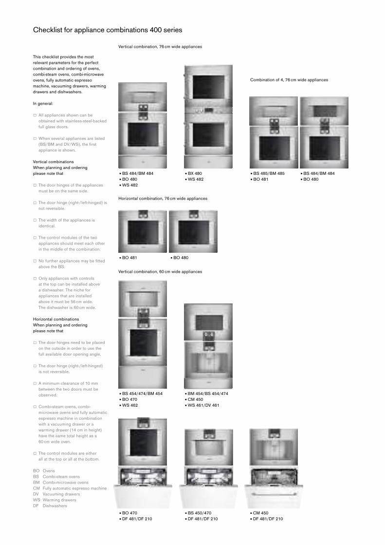
This checklist provides the most
relevant parameters for the perfect
combination and ordering of ovens,
combi-steam ovens, combi-microwave
ovens, fully automatic espresso
machine, vacuuming drawers, warming
drawers and dishwashers.
In general:
□ Allappliancesshowncanbe obtained with stainless-steel-backed
full glass doors.
□ Whenseveralappliancesarelisted(BS/BMandDV/WS),thefirstappliance is shown.
Vertical combinations
When planning and ordering
please note that
□ Thedoorhingesoftheappliancesmust be on the same side.
□ Thedoorhinge(right-/left-hinged)isnot reversible.
□ Thewidthoftheappliancesisidentical.
□ Thecontrolmodulesofthetwoappliances should meet each other
in the middle of the combination.
□ Nofurtherappliancesmaybefittedabove the BS.
□ Onlyapplianceswithcontrols at the top can be installed above
a dishwasher. The niche for
appliances that are installed
above it must be 56 cm wide.
The dishwasher is 60 cm wide.
Horizontal combinations
When planning and ordering
please note that
□ Thedoorhingesneedtobeplacedon the outside in order to use the
full available door opening angle.
□ Thedoorhinge(right-/left-hinged)is not reversible.
□ Aminimumclearanceof10mmbetween the two doors must be
observed.
□ Combi-steamovens,combi-microwave ovens and fully automatic
espresso machine in combination
with a vacuuming drawer or a
warming drawer (14 cm in height)
have the same total height as a
60 cm wide oven.
□ Thecontrolmodulesareeither all at the top or all at the bottom.
BO Ovens
BS Combi-steam ovens
BM Combi-microwave ovens
CM Fully automatic espresso machine
DV Vacuuming drawers
WS Warming drawers
DF Dishwashers
▪BS484/BM484▪BO480▪WS482
▪BS485/BM485 ▪BS484/BM484▪BO481 ▪BO480
▪BO481 ▪BO480
▪BX480▪WS482
▪BO470▪DF481/DF210
▪BS450/470▪DF481/DF210
▪CM450▪DF481/DF210
▪BS454/474/BM454▪BO470▪WS462
▪BM454/BS454/474▪CM450▪WS461/DV461
Checklist for appliance combinations 400 series
Horizontal combination, 76 cm wide appliances
Vertical combination, 60 cm wide appliances
Vertical combination, 76 cm wide appliances
Combination of 4, 76 cm wide appliances

7Ovens 400 series
▪BO471
▪BO471
▪BS455/475/BM455▪BO471
▪BS471/451▪WS461/DV461
▪BS471/451▪WS461/DV461
▪CM450▪WS461/DV461
▪BM454/BS474/454▪CM450▪DV461/WS461
▪CM450▪DV461/WS461
▪BO470
▪BS470/450▪DV461/WS461
▪BS470/450▪DV461/WS461
▪BS470/450▪WS461/DV461
▪CM450▪DV461/WS461
▪BO471 ▪BS470/450▪DV461/WS461
▪BO471 ▪CM450▪WS461/DV461
Combination of 4 with warming drawer, 60 cm wide appliances
Horizontal combination, 60 cm wide appliances
▪BS471/451▪WS461/DV461

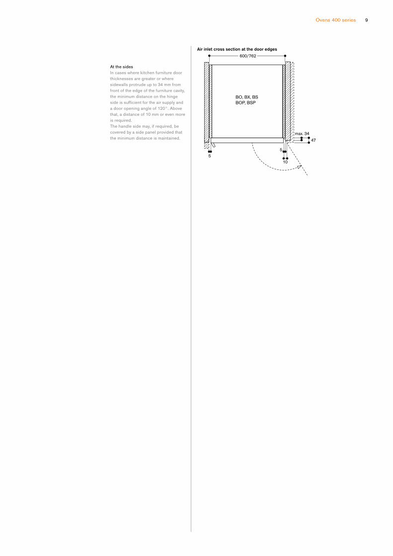
General notes
Necessaryaircrosssection at the door edges
Installation behind kitchen
furniture doors
Appropriate measures must be taken
to prevent these types of doors from
closing when the appliance is heating
or while it is cooling down (fan
operation).
Combination of ovens and Vario
cooling 400 series appliances
Please check the planning notes
in the information for Vario cooling
400 series appliances in order to
prevent the refrigerator door from
colliding with the oven.
Installation side by side
When appliances are installed side
by side, the clearance between the
appliances must be at least 10 mm
(corresponds to the standard outside
measurement of the furniture cavity
of 600 or 762 mm).
The door hinges need to be placed
outside in order to use the full available
door opening angle.
Gaggenau ovens 400 series are cooled
with fresh air at the top edge and side
edges of the door. Hot air is blown out
at the door bottom edge. Combi-steam
ovens and Combi-microwave ovens
have the air inlet at the side edges of
the door and the hot air and steam
outlets at the top edge of the door.
In order to prevent appliances from
overheating and to ensure that they
cool down as required after operation,
appropriate minimum cross sections
of free space must be maintained from
kitchen furniture edges.
The measurements given in the
drawing apply to all appliances.
The following must also be observed:
The area above the appliances
BS:
No other electrical appliances
should be installed above the BS.
It is recommended that a horizontal
handle is not fitted on furniture above the BS.
Where the edge of a kitchen unit
protrudes more than 20 mm from
the front edge of the furniture cavity,
the edge of the kitchen furniture
panel must be steam resistant as is
the case above a dishwasher. Steam
may possibly penetrate into the
compartment.
The area below the appliances
DV / WS:
It must be ensured that there is
sufficientaccesstotheloweredgeofthe vacuuming drawer and warming
drawer, if the thickness of the kitchen
furniture door is greater than 20 mm in
front of the furniture cavity.
Planning notes for the installation of ovens and oven combinations 400 and 200 series
BO, BX, BS,
BM, CM, WS, DV
BOP, BSP, BMP, CMP, WSP
9Ovens 400 series
At the sides
In cases where kitchen furniture door
thicknesses are greater or where
sidewalls protrude up to 34 mm from
front of the edge of the furniture cavity,
the minimum distance on the hinge
sideissufficientfortheairsupplyanda door opening angle of 120°. Above
that, a distance of 10 mm or even more
is required.
The handle side may, if required, be
covered by a side panel provided that
the minimum distance is maintained.
BO, BX, BS
BOP, BSP
Controls at the top
Right-hinged
BO 480 112
Stainless steel-backed full glass door
Width 76 cm
Left-hinged
BO 481 112
Stainless steel-backed full glass door
Width 76 cm
Included in the price
1 baking tray, enamelled pyrolysis-safe
1 rotisserie spit
1 wire rack
1 grill tray with wire rack
1 plug-in core temperature probe
Special accessories
BA 018 105
Pull-out system
Fully extendable telescopic rails
and enamelled cast iron frame.
BA 058 115
Heating element for baking stone
and Gastronorm roaster.
BA 058 133
Baking stone.
Incl. baking stone support and pizza
paddle (heating element must be
ordered separately).
Notincombinationwithpull-outsystem.
GN 340 230
Gastronorm roaster in cast aluminium.
GN2/3,height165mm,non-stick.
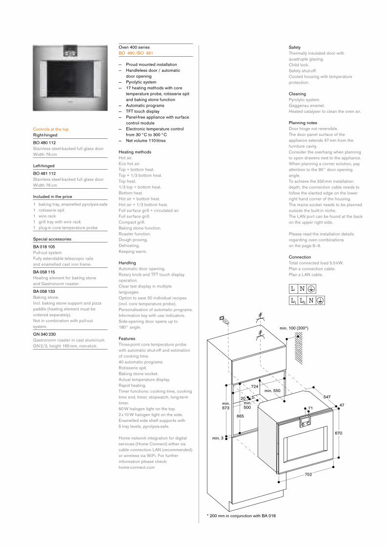
Oven 400 series
BO 480 /BO 481
— Proud mounted installation
— Handleless door / automatic
door opening
— Pyrolytic system
— 17 heating methods with core
temperature probe, rotisserie spit
and baking stone function
— Automatic programs
— TFT touch display
— Panel-free appliance with surface
control module
— Electronic temperature control
from 30 °C to 300 °C
— Netvolume110litres
Heating methods
Hot air.
Eco hot air.
Top + bottom heat.
Top + 1/3 bottom heat.
Top heat.
1/3 top + bottom heat.
Bottom heat.
Hot air + bottom heat.
Hot air + 1/3 bottom heat.
Full surface grill + circulated air.
Full surface grill.
Compact grill.
Baking stone function.
Roaster function.
Dough proving.
Defrosting.
Keeping warm.
Handling
Automatic door opening.
Rotary knob and TFT touch display
operation.
Clear text display in multiple
languages.
Option to save 50 individual recipes
(incl. core temperature probe).
Personalisation of automatic programs.
Information key with use indicators.
Side-opening door opens up to
180° angle.
Features
Three-point core temperature probe
withautomaticshut-offandestimationof cooking time.
40 automatic programs.
Rotisserie spit.
Baking stone socket.
Actual temperature display.
Rapid heating.
Timer functions: cooking time, cooking
time end, timer, stopwatch, long-term
timer.
60 W halogen light on the top.
2 x 10 W halogen light on the side.
Enamelled side shelf supports with
5 tray levels, pyrolysis-safe.
Home network integration for digital
services (Home Connect) either via
cableconnectionLAN(recommended)or wireless via WiFi. For further
information please check:
home-connect.com
Safety
Thermally insulated door with
quadruple glazing.
Child lock.
Safetyshut-off.Cooled housing with temperature
protection.
Cleaning
Pyrolytic system.
Gaggenau enamel.
Heated catalyser to clean the oven air.
Planning notes
Door hinge not reversible.
The door panel surface of the
appliance extends 47 mm from the
furniture cavity.
Consider the overhang when planning
to open drawers next to the appliance.
When planning a corner solution, pay
attention to the 90° door opening
angle.
To achieve the 550 mm installation
depth, the connection cable needs to
follow the slanted edge on the lower
right hand corner of the housing.
The mains socket needs to be planned
outside the built-in niche.
TheLANportcanbefoundatthebackon the upper right side.
Please read the installation details
regarding oven combinations
on the page 8–9.
Connection
Total connected load 5.5 kW.
Plan a connection cable.
PlanaLANcable.
11Ovens 400 series
Controls at the top
Right-hinged
BO 470 112
Stainless steel-backed full glass door
Width 60 cm
Left-hinged
BO 471 112
Stainless steel-backed full glass door
Width 60 cm
Included in the price
2 baking trays, enamelled pyrolysis-safe
1 rotisserie spit
1 glass tray
1 wire rack
1 grill tray with wire rack
1 plug-in core temperature probe
Special accessories
BA 016 105
Pull-out system
Fully extendable telescopic rails
and enamelled cast iron frame.
BA 056 115
Heating element for baking stone
and Gastronorm roaster.
BA 056 133
Baking stone.
Incl. baking stone support and pizza
paddle (heating element must be
ordered separately).
Notincombinationwithpull-outsystem.
G N 340 230
Gastronorm roaster in cast aluminium.
GN2/3,height165mm,non-stick.
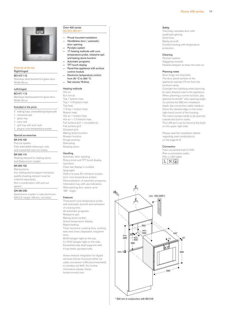
Oven 400 series
B O 470 /B O 471
— Proud mounted installation
— Handleless door / automatic
door opening
— Pyrolytic system
— 17 heating methods with core
temperature probe, rotisserie spit
and baking stone function
— Automatic programs
— TFT touch display
— Panel-free appliance with surface
control module
— Electronic temperature control
from 30 °C to 300 °C
— Netvolume76litres
Heating methods
Hot air.
Eco hot air.
Top + bottom heat.
Top + 1/3 bottom heat.
Top heat.
1/3 top + bottom heat.
Bottom heat.
Hot air + bottom heat.
Hot air + 1/3 bottom heat.
Full surface grill + circulated air.
Full surface grill.
Compact grill.
Baking stone function.
Roaster function.
Dough proving.
Defrosting.
Keeping warm.
Handling
Automatic door opening.
Rotary knob and TFT touch display
operation.
Clear text display in multiple
languages.
Option to save 50 individual recipes
(incl. core temperature probe).
Personalisation of automatic programs.
Information key with use indicators.
Side-opening door opens up to
180° angle.
Features
Three-point core temperature probe
withautomaticshut-offandestimationof cooking time.
40 automatic programs.
Rotisserie spit.
Baking stone socket.
Actual temperature display.
Rapid heating.
Timer functions: cooking time, cooking
time end, timer, stopwatch, long-term
timer.
60 W halogen light on the top.
2 x 10 W halogen light on the side.
Enamelled side shelf supports with
4 tray levels, pyrolysis-safe.
Home network integration for digital
services (Home Connect) either via
cableconnectionLAN(recommended)or wireless via WiFi. For further
information please check:
home-connect.com
Safety
Thermally insulated door with
quadruple glazing.
Child lock.
Safetyshut-off.Cooled housing with temperature
protection.
Cleaning
Pyrolytic system.
Gaggenau enamel.
Heated catalyser to clean the oven air.
Planning notes
Door hinge not reversible.
The door panel surface of the
appliance extends 47 mm from the
furniture cavity.
Consider the overhang when planning
to open drawers next to the appliance.
When planning a corner solution, pay
attention to the 90° door opening angle.
To achieve the 550 mm installation
depth, the connection cable needs to
follow the slanted edge on the lower
right hand corner of the housing.
The mains socket needs to be planned
outside the built-in niche.
TheLANportcanbefoundatthebackon the upper right side.
Please read the installation details
regarding oven combinations
on the page 8–9.
Connection
Total connected load 3.7 kW.
Plan a connection cable.
PlanaLANcable.

Controls centred
Right-hinged
BX 480 112
Stainless steel-backed full glass door
Width 76 cm
Left-hinged
BX 481 112
Stainless steel-backed full glass door
Width 76 cm
Included in the price
2 baking trays, enamelled pyrolysis-safe
1 rotisserie spit
2 wire racks
2 grill trays with wire rack
1 plug-in core temperature probe
Special accessories
BA 018 105
Pull-out system
Fully extendable telescopic rails
and enamelled cast iron frame.
BA 058 115
Heating element for baking stone
and Gastronorm roaster.
BA 058 133
Baking stone.
Incl. baking stone support and pizza
paddle (heating element must be
ordered separately).
Notincombinationwithpull-outsystem.
GN 340 230
Gastronorm roaster in cast aluminium.
GN2/3,height165mm,non-stick.
Double oven 400 series
BX 480 /BX 481
— Proud mounted installation
— Pyrolytic system
— 17 heating methods with core
temperature probe, rotisserie spit
and baking stone function
— TFT touch display
— Electronic temperature control
from 30 °C to 300 °C
— 2 x 110 litres net volume
Heating methods
Hot air.
Eco hot air.
Top + bottom heat.
Top + 1/3 bottom heat.
Top heat.
1/3 top + bottom heat.
Bottom heat.
Hot air + bottom heat.
Hot air + 1/3 bottom heat.
Full surface grill + circulated air.
Full surface grill.
Compact grill.
Baking stone function.
Roaster function.
Dough proving.
Defrosting.
Keeping warm.
Handling
Rotary knob and TFT touch display
operation.
Clear text display in multiple
languages.
Information key with use indicators.
Side-opening door opens up to
180° angle.
Features
Three-point core temperature probe
withautomaticshut-offandestimationof cooking time.
Rotisserie spit (lower oven).
Baking stone socket.
Actual temperature display.
Rapid heating.
Timer functions: cooking time, cooking
time end, timer, stopwatch, long-term
timer.
60 W halogen light on the top.
10 W halogen light on the side.
Enamelled side shelf supports with
5 tray levels, pyrolysis-safe.
Safety
Thermally insulated door with
quadruple glazing.
Child lock.
Safetyshut-off.Cooled housing with temperature
protection.
Cleaning
Pyrolytic system.
Gaggenau enamel.
Heated catalyser to clean the oven air.
Planning notes
Door hinge not reversible.
The door panel surface of the
appliance extends 47 mm from the
furniture cavity.
Consider the overhang when planning
to open drawers next to the appliance.
When planning a corner solution, pay
attention to the 90° door opening angle.
To achieve the 550 mm installation
depth, the connection cable needs to
follow the slanted edge on the lower
right hand corner of the housing.
The mains socket needs to be planned
outside the built-in niche.
Please read the installation details
regarding oven combinations
on the page 8–9.
Connection
Total connected load 9.2 kW.
Plan a connection cable.

13Ovens 400 series
Controls at the bottom
Right-hinged
BS 484 112
Stainless steel-backed full glass door
Width 76 cm
Left-hinged
BS 485 112
Stainless steel-backed full glass door
Width 76 cm
Included in the price
1 cooking container, stainless steel,
perforated
1 cooking container, stainless steel,
unperforated
1 wire rack
1 plug-in core temperature probe
1 outlet hose (3 m long)
1 water inlet hose (3 m long)
4 cleaning cartridge
Installation accessories
GF 111 100
Water descaling system
GF 121 110
Filter cartridge
G Z 010 011
Extension for water inlet and outlet
(2 m long)
Special accessories
B A 010 301
Triple telescopic pull-out rack
For combi-steam oven.
B A 020 380
Cooking container, non-stick,
unperforated, 40 mm deep, 5 l.
B A 020 390
Cooking container, non-stick,
perforated, 40 mm deep, 5 l.
G N 340 230
Gastronorm roaster in cast aluminium.
GN2/3,height165mm,non-stick.
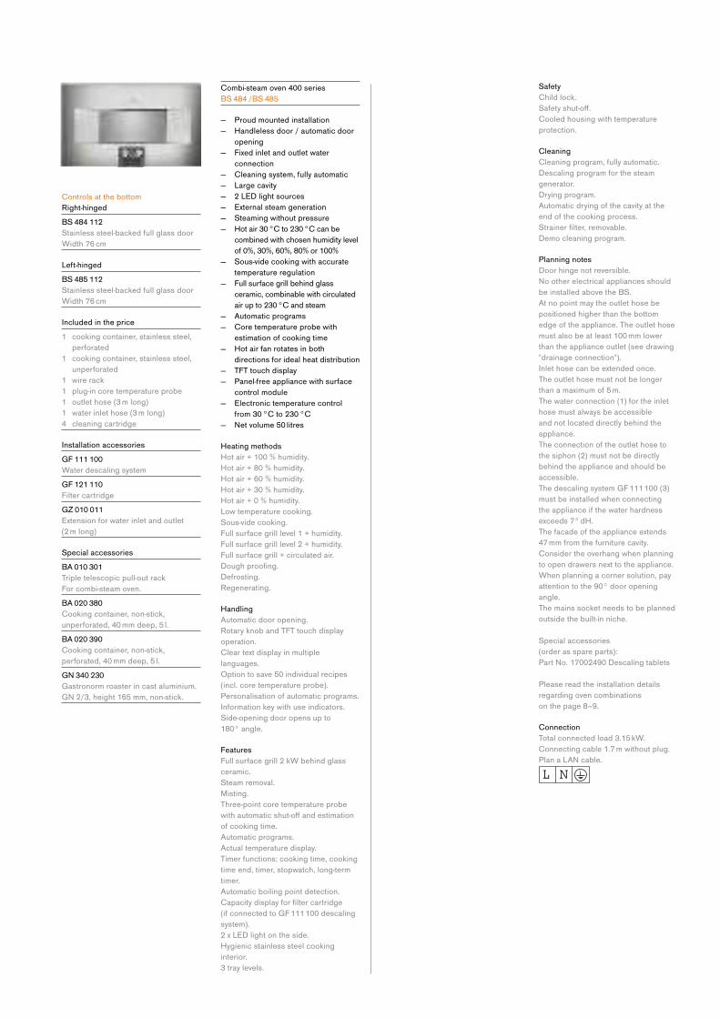
Combi-steam oven 400 series
B S 484 /B S 485
— Proud mounted installation
— Handleless door / automatic door
opening
— Fixed inlet and outlet water
connection
— Cleaning system, fully automatic
— Large cavity
— 2 LED light sources
— External steam generation
— Steaming without pressure
— Hot air 30 °C to 230 °C can be
combined with chosen humidity level
of 0%, 30%, 60%, 80% or 100%
— Sous-vide cooking with accurate
temperature regulation
— Full surface grill behind glass
ceramic, combinable with circulated
air up to 230 °C and steam
— Automatic programs
— Core temperature probe with
estimation of cooking time
— Hot air fan rotates in both
directions for ideal heat distribution
— TFT touch display
— Panel-free appliance with surface
control module
— Electronic temperature control
from 30 °C to 230 °C
— Netvolume50litres
Heating methods
Hot air + 100 % humidity.
Hot air + 80 % humidity.
Hot air + 60 % humidity.
Hot air + 30 % humidity.
Hot air + 0 % humidity.
Low temperature cooking.
Sous-vide cooking.
Full surface grill level 1 + humidity.
Full surface grill level 2 + humidity.
Full surface grill + circulated air.
Doughproofing. Defrosting.
Regenerating.
Handling
Automatic door opening.
Rotary knob and TFT touch display
operation.
Clear text display in multiple
languages.
Option to save 50 individual recipes
(incl. core temperature probe).
Personalisation of automatic programs.
Information key with use indicators.
Side-opening door opens up to
180° angle.
Features
Full surface grill 2 kW behind glass
ceramic.
Steam removal.
Misting.
Three-point core temperature probe
withautomaticshut-offandestimationof cooking time.
Automatic programs.
Actual temperature display.
Timer functions: cooking time, cooking
time end, timer, stopwatch, long-term
timer.
Automatic boiling point detection.
Capacitydisplayforfiltercartridge (if connected to GF 111 100 descaling
system).
2 x LED light on the side.
Hygienic stainless steel cooking
interior.
3 tray levels.
Safety
Child lock.
Safetyshut-off.Cooled housing with temperature
protection.
Cleaning
Cleaning program, fully automatic.
Descaling program for the steam
generator.
Drying program.
Automatic drying of the cavity at the
end of the cooking process.
Strainerfilter,removable.Demo cleaning program.
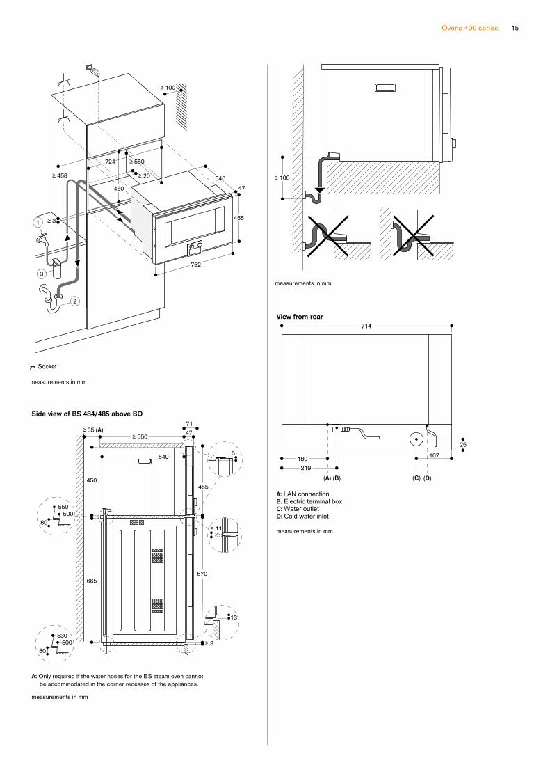
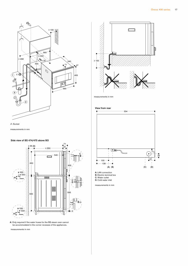
Planning notes
Door hinge not reversible.
Nootherelectricalappliancesshouldbe installed above the BS.
At no point may the outlet hose be
positioned higher than the bottom
edge of the appliance. The outlet hose
must also be at least 100 mm lower
than the appliance outlet (see drawing
"drainage connection").
Inlet hose can be extended once.
The outlet hose must not be longer
than a maximum of 5 m.
The water connection (1) for the inlet
hose must always be accessible
and not located directly behind the
appliance.
The connection of the outlet hose to
the siphon (2) must not be directly
behind the appliance and should be
accessible.
The descaling system GF 111 100 (3)
must be installed when connecting
the appliance if the water hardness
exceeds 7° dH.
The facade of the appliance extends
47 mm from the furniture cavity.
Consider the overhang when planning
to open drawers next to the appliance.
When planning a corner solution, pay
attention to the 90° door opening
angle.
The mains socket needs to be planned
outside the built-in niche.
Special accessories
(order as spare parts):
PartNo.17002490Descalingtablets
Please read the installation details
regarding oven combinations
on the page 8–9.
Connection
Total connected load 3.15 kW.
Connecting cable 1.7 m without plug.
PlanaLANcable.
15Ovens 400 series

Controls at the top
Right-hinged
B S 470 112
Stainless steel-backed full glass door
Width 60 cm
Left-hinged
B S 471 112
Stainless steel-backed full glass door
Width 60 cm
Controls at the bottom
Right-hinged
B S 474 112
Stainless steel-backed full glass door
Width 60 cm
Left-hinged
B S 475 112
Stainless steel-backed full glass door
Width 60 cm
Included in the price
1 cooking container, stainless steel,
perforated
1 cooking container, stainless steel,
unperforated
1 wire rack
1 plug-in core temperature probe
1 outlet hose (3 m long)
1 water inlet hose (3 m long)
4 cleaning cartridge
Installation accessories
G F 111 100
Water descaling system
G F 121 110
Filter cartridge
G Z 010 011
Extension for water inlet and outlet
(2 m long)
Special accessories
B A 010 301
Triple telescopic pull-out rack
For combi-steam oven.
B A 020 380
Cooking container, non-stick,
unperforated, 40 mm deep, 5 l.
B A 020 390
Cooking container, non-stick,
perforated, 40 mm deep, 5 l.
G N 340 230
Gastronorm roaster in cast aluminium.
GN2/3,height165mm,non-stick.
Combi-steam oven 400 series
B S 470 /B S 471 /B S 474 /B S 475
— Proud mounted installation
— Handleless door / automatic door
opening
— Fixed inlet and outlet water
connection
— Cleaning system, fully automatic
— Large cavity
— 2 LED light sources
— External steam generation
— Steaming without pressure
— Hot air 30 °C to 230 °C can be
combined with chosen humidity level
of 0%, 30%, 60%, 80% or 100%
— Sous-vide cooking with accurate
temperature regulation
— Full surface grill behind glass
ceramic, combinable with circulated
air up to 230 °C and steam
— Automatic programs
— Core temperature probe with
estimation of cooking time
— Hot air fan rotates in both
directions for ideal heat distribution
— TFT touch display
— Panel-free appliance with surface
control module
— Electronic temperature control
from 30 °C to 230 °C
— Netvolume50litres
Heating methods
Hot air + 100 % humidity.
Hot air + 80 % humidity.
Hot air + 60 % humidity.
Hot air + 30 % humidity.
Hot air + 0 % humidity.
Low temperature cooking.
Sous-vide cooking.
Full surface grill level 1 + humidity.
Full surface grill level 2 + humidity.
Full surface grill + circulated air.
Doughproofing. Defrosting.
Regenerating.
Handling
Automatic door opening.
Rotary knob and TFT touch display
operation.
Clear text display in multiple
languages.
Option to save 50 individual recipes
(incl. core temperature probe).
Personalisation of automatic programs.
Information key with use indicators.
Side-opening door opens up to
180° angle.
Features
Full surface grill 2 kW behind glass
ceramic.
Steam removal.
Misting.
Three-point core temperature probe
withautomaticshut-offandestimationof cooking time.
Automatic programs.
Actual temperature display.
Timer functions: cooking time, cooking
time end, timer, stopwatch, long-term
timer.
Automatic boiling point detection.
Capacitydisplayforfiltercartridge (if connected to GF 111 100 descaling
system).
2 x LED light on the side.
Hygienic stainless steel cooking
interior.
3 tray levels.
Safety
Child lock.
Safetyshut-off.Cooled housing with temperature
protection.
Cleaning
Cleaning program, fully automatic.
Descaling program for the steam
generator.
Drying program.
Automatic drying of the cavity at the
end of the cooking process.
Strainerfilter,removable.Demo cleaning program.
Planning notes
Door hinge not reversible.
Nootherelectricalappliancesshouldbe installed above the BS.
At no point may the outlet hose be
positioned higher than the bottom
edge of the appliance. The outlet hose
must also be at least 100 mm lower
than the appliance outlet (see drawing
"drainage connection").
Inlet hose can be extended once.
The outlet hose must not be longer
than a maximum of 5 m.
The water connection (1) for the inlet
hose must always be accessible
and not located directly behind the
appliance.
The connection of the outlet hose to
the siphon (2) must not be directly
behind the appliance and should be
accessible.
The descaling system GF 111 100 (3)
must be installed when connecting
the appliance if the water hardness
exceeds 7° dH.
The facade of the appliance extends
47 mm from the furniture cavity.
Consider the overhang when planning
to open drawers next to the appliance.
When planning a corner solution, pay
attention to the 90° door opening
angle.
The mains socket needs to be planned
outside the built-in niche.
Special accessories
(order as spare parts):
PartNo.17002490Descalingtablets
Please read the installation details
regarding oven combinations
on the page 8–9.
Connection
Total connected load 3.15 kW.
Connecting cable 1.7 m without plug.
PlanaLANcable.
17Ovens 400 series

Controls at the top
Right-hinged
B S 450 111
Stainless steel-backed full glass door
Width 60 cm
Left-hinged
B S 451 111
Stainless steel-backed full glass door
Width 60 cm
Controls at the bottom
Right-hinged
B S 454 111
Stainless steel-backed full glass door
Width 60 cm
Left-hinged
B S 455 111
Stainless steel-backed full glass door
Width 60 cm
Included in the price
1 Cooking container, stainless steel,
perforated
1 Cooking container, stainless steel,
unperforated
1 wire rack
1 plug-in core temperature probe
4 cleaning cartridge
Special accessories
B A 010 301
Triple telescopic pull-out rack
For combi-steam oven.
B A 020 380
Cooking container, non-stick,
unperforated, 40 mm deep, 5 l.
B A 020 390
Cooking container, non-stick,
perforated, 40 mm deep, 5 l.
G N 340 230
Gastronorm roaster in cast aluminium.
GN2/3,height165mm,non-stick.
Combi-steam oven 400 series
B S 450 /B S 451 /B S 454 /B S 455
— Proud mounted installation
— Handleless door / automatic door
opening
— Water tank for fresh and waste
water
— Cleaning system, fully automatic
— Large cavity
— 2 LED light sources
— External steam generation
— Steaming without pressure
— Hot air 30 °C to 230 °C can be
combined with chosen humidity level
of 0%, 30%, 60%, 80% or 100%
— Sous-vide cooking with accurate
temperature regulation
— Full surface grill behind glass
ceramic, combinable with
circulated air up to 230 °C and
steam
— Automatic programs
— Core temperature probe with
estimation of cooking time
— Hot air fan rotates in both
directions for ideal heat distribution
— TFT touch display
— Panel-free appliance with surface
control module
— Electronic temperature control
from 30 °C bis 230 °C
— Netvolume50litres
Heating methods
Hot air + 100 % humidity.
Hot air + 80 % humidity.
Hot air + 60 % humidity.
Hot air + 30 % humidity.
Hot air + 0 % humidity.
Low temperature cooking.
Sous-vide cooking.
Full surface grill level 1 + humidity.
Full surface grill level 2 + humidity.
Full surface grill + circulated air.
Doughproofing. Defrosting.
Regenerating.
Handling
Automatic door opening.
Rotary knob and TFT touch display
operation.
Clear text display in multiple
languages.
Option to save individual recipes
(incl. core temperature probe).
Personalisation of automatic programs.
Information key with use indicators.
Side-opening door opens up to
180° angle.
Features
Full surface grill 2 kW behind glass
ceramic.
2 removable 1.7 litre water tanks.
Misting.
Water level warning.
Three-point core temperature probe
withautomaticshut-offandestimationof cooking time.
Automatic programs.
Actual temperature display.
Timer functions: cooking time, cooking
time end, timer, stopwatch, long-term
timer.
Automatic boiling point detection.
2 x LED light on the side.
Hygienic stainless steel cooking
interior.
3 tray levels.
Safety
Child lock.
Safetyshut-off.Cooled housing with temperature
protection.
Cleaning
Cleaning program, fully automatic.
Descaling program for the steam
generator.
Drying program.
Automatic drying of the cavity at the
end of the cooking process.
Strainerfilter,removable.Water tank, dishwasher-safe.
Demo cleaning program.
Planning notes
Door hinge not reversible.
Nootherelectricalappliancesshouldbe installed above the BS.
The facade of the appliance extends
47 mm from the furniture cavity.
Consider the overhang when planning
to open drawers next to the appliance.
When planning a corner solution, pay
attention to the 90° door opening angle.
The mains socket needs to be planned
outside the built-in niche.
Special accessories
(order as spare parts):
PartNo.17002490Descalingtablets
Please read the installation details
regarding oven combination on
page 8–9.
Connection
Total connected load 3.15 kW.
Connecting cable 1.7 m with plug.
PlanaLANcable.

19Ovens 400 series

Controls at the bottom
Right-hinged
B M 484 110
Stainless steel-backed full glass door
Width 76 cm
Left-hinged
B M 485 110
Stainless steel-backed full glass door
Width 76 cm
Included in the price
1 combination wire rack
1 glass tub
Combi-microwave oven 400 series
B M 484 /B M 485
— Proud mounted installation
— Handleless door / automatic door
opening
— Single operation and combination
of microwave, grill and oven
— Sequential operation of up to
5 modes incl. programing of
combined operation and rest time
— TFT touch display
— Panel-free appliance with surface
control module
— Electronic temperature control
— Interior volume 36 litres
Programs
Microwave operation with 5 output
levels: 1000, 600, 360, 180, 90 W.
Oven operation with 4 heating
methods:
Hot air 40 °C and from
100 °C to 250 °C,
Full surface grill + hot air from
100 °C to 250 °C,
Full surface grill + circulated air from
100 °C to 250 °C,
Full surface grill with 3 levels of
intensity, maximum output 2000 W.
Heating methods with microwave
output levels 600, 360, 180 and 90 W
freely combinable.
15 automatic programs with weight
indication, customisable:
4 defrosting programs
4 cooking programs
7 combination programs
Option to save 50 individual recipes.
Handling
Automatic door opening.
Rotary knob and TFT touch display
operation.
Clear text display in multiple
languages.
Information key with use indicators.
Side-opening door opens up to
180° angle.
Features
Rapid heating.
4 tray levels.
Actual temperature display.
60 W halogen light on the side.
Safety
Thermally insulated door with triple
glazing.
Triple door lock.
Child lock.
Safetyshut-off.Cooled housing with temperature
protection.
Cleaning
Hygienic stainless steel interior with
glass ceramic base.
Interior back wall with catalytic coating.
Planning notes
Door hinge not reversible.
The door panel surface of the
appliance extends 47 mm from the
furniture cavity.
Consider the overhang when planning
to open drawers next to the appliance.
When planning a corner solution, pay
attention to the 110° door opening
angle.
The mains socket needs to be planned
outside of the built-in niche.
Please read the installation details
regarding oven combinations on
page 8–9.
Connection
Total connected load 3.1 kW.
Connection cable 1.5 m without plug.
21Ovens 400 series
Controls at the bottom
Right-hinged
B M 454 110
Stainless steel-backed full glass door
Width 60 cm
Left-hinged
B M 455 110
Stainless steel-backed full glass door
Width 60 cm
Included in the price
1 combination wire rack
1 glass tub
Combi-microwave oven 400 series
B M 454 /B M 455
— Proud mounted installation
— Handleless door / automatic door
opening
— Single operation and combination
of microwave, grill and oven
— Sequential operation of up to
5 modes incl. programing of
combined operation and rest time
— TFT touch display
— Panel-free appliance with surface
control module
— Electronic temperature control
— Interior volume 36 litres
Programs
Microwave operation with 5 output
levels: 1000, 600, 360, 180, 90 W.
Oven operation with 4 heating
methods:
Hot air 40 °C and from
100 °C to 250 °C,
Full surface grill + hot air from
100 °C to 250 °C,
Full surface grill + circulated air from
100 °C to 250 °C
Full surface grill with 3 levels of
intensity, maximum output 2000 W.
Heating methods with microwave
output levels 600, 360, 180 and 90 W
freely combinable.
15 automatic programs with weight
indication, customisable:
4 defrosting programs
4 cooking programs
7 combination programs
Option to save 50 individual recipes.
Handling
Automatic door opening.
Rotary knob and TFT touch display
operation.
Clear text display in multiple
languages.
Information key with use indicators.
Side-opening door opens up to
180° angle.
Features
Rapid heating.
4 tray levels.
Actual temperature display.
60 W halogen light on the side.
Safety
Thermally insulated door with triple
glazing.
Triple door lock.
Child lock.
Safetyshut-off.Cooled housing with temperature
protection.
Cleaning
Hygienic stainless steel interior with
glass ceramic base.
Interior back wall with catalytic coating.
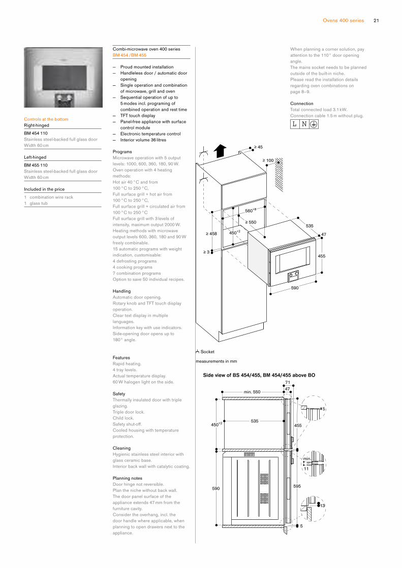
Planning notes
Door hinge not reversible.
Plan the niche without back wall.
The door panel surface of the
appliance extends 47 mm from the
furniture cavity.
Consider the overhang, incl. the
door handle where applicable, when
planning to open drawers next to the
appliance.
When planning a corner solution, pay
attention to the 110° door opening
angle.
The mains socket needs to be planned
outside of the built-in niche.
Please read the installation details
regarding oven combinations on
page 8–9.
Connection
Total connected load 3.1 kW.
Connection cable 1.5 m without plug.
Controls at the top
Left-hinged
C M 450 112
Stainless steel-backed full glass door
Width 60 cm
Included in the price
1 assembly screws
1 scoop
1 test strip
1 milk container (insulated)
1 connection hose for milk frother
1 milk pipe
Fully automatic espresso machine
400 series
CM 450
— Handleless door / automatic door
opening
— Continuousflowheatermeansnowaiting time and constant brewing
temperature
— Aroma brewing technology for a
full aroma
— Single portion cleaning
— TFT touch display
— Panel-free appliance with surface
control module
— One-touch operation
— Personalisation function
— 7 light settings
— Electronicfilllevelcontrolformilk,waterandcoffeetoensureaperfect result
Type of beverage
Ristretto / 2 x Ristretto.
Espresso / 2 x Espresso.
Espresso Macchiato / 2 x Espresso
Macchiato.
Coffee/2xCoffee. Americano / 2 x Americano.
CaffeLatte/2xCaffeLatte. Latte Macchiato / 2 x Latte Macchiato.
Cappuccino / 2 x Cappuccino.
Flat White / 2 x Flat White.
Milk froth / 2 x Milk froth.
Warm milk / 2 x Warm milk.
Hot water / 2 x Hot water.
Handling
Automatic door opening.
Rotary knob and TFT touch display
operation.
Clear text display.
Personalisation function, option to
save 8 individualised beverages.
4 beverage size settings, volume can
be individually adjusted to match the
size of the cup.
8coffeestrengthlevelsfromverymildto extra strong.
3coffeetemperaturelevels.10 hot water temperature levels.
4coffee-milkratiolevels.Adjustable grinding level.
Height-adjustablecoffeedispenser7 cm to 15 cm.
Easy access to water tank, milk and
coffeebeancontainerbehindthedoor.
Features
Maintenance-free grinding unit with
ceramic discs.
Separate drawer for second ground
coffeetype.Water pump with 19 bar pressure.
Double grinding and brewing cycles
for extra intensity for single beverage
order.
For double beverage order, two
grinding and brewing cycles.
Beverage dispenser with integrated
milk system.
Insulated stainless steel milk container
for up to 0.5 litres.
Integrated lightning with LEDs.
Removable bean container with aroma
protecting lid for 500 g allows for an
effortlessexchangeofdifferenttypesofcoffeebeans.Automaticadjustmentofgroundcoffeequantity.
Removable 2.4 litre water tank.
Electronicwaterfilterexchangeindicator.
Electronicfilllevelcontrolfordriptrayandcontainerforcoffeeresidue.
Home network integration for digital
services (Home Connect) either via
cableconnectionLAN(recommended)or wireless via WiFi. For further
information please check:
home-connect.com
Safety
Child lock.
Cleaning
Fully automatic rinse programme when
machineisturnedon/off.Automatic steam cleaning of the milk
system after every beverage.
Automatic cleaning and descaling
programme.
Emptying programme to prepare the
appliance for holiday or transportation.
Empty-grinding function to remove
coffeeresiduesfromthesystemwhenswitching bean types.
Removable brewing unit.
Dishwasher-safecoffeeresiduecontainer and drip tray.
Dishwasher-safe beverage dispenser.
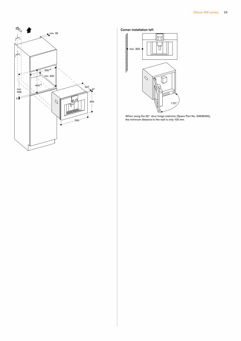
Planning notes
Ideal installation height 95 cm to
145 cm (top edge of niche bottom).
The door panel surface of the
appliance extends 47 mm from the
furniture cavity.
When installing in a corner a side
clearance is required.
Door opening angle appr. 110°
(delivery status) - mounting distance to
the wall has to be at least 350 mm.
Door opening angle appr. 155° -
mounting distance to the wall has to be
at least 650 mm.
Door opening angle appr. 92° -
mounting distance to the wall has to
beatleast100mm(sparepartNo.00636455).
Installation directly above 14 cm high
warming drawer in 59 cm standardised
niche.
TheLANportcanbefoundatthebackon the lower right side.
Special accessories (order as spare
parts):
PartNo.17000705Waterfilter PartNo.00311819Descalingtablets
PartNo.00311769Cleaningtablets
PartNo.00636455Doorhingerestrictor (92° opening angle)
PartNo.11015223Beancontainerwith lid
Please read the installation details
regarding oven combination on
page 8–9.
Connection
Total connected load 1.6 kW.
Connection cable 1.7 m with plug.
PlanaLANcable.
23Ovens 400 series
min. 35
min.
458
min. 400
450+2
560+8
5
590
455
47347
When using the 92° door hinge restrictor (Spare Part No. 00636455),
the minimum distance to the wall is only 100 mm.
min. 350
Corner installation left
110°
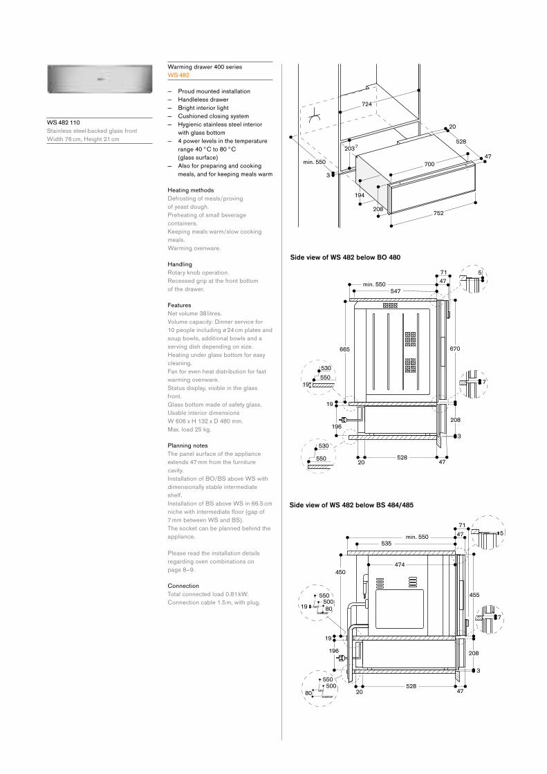
W S 482 110
Stainless steel-backed glass front
Width 76 cm, Height 21 cm
Warming drawer 400 series
W S 482
— Proud mounted installation
— Handleless drawer
— Bright interior light
— Cushioned closing system
— Hygienic stainless steel interior
with glass bottom
— 4 power levels in the temperature
range 40 °C to 80 °C
(glass surface)
— Also for preparing and cooking
meals, and for keeping meals warm
Heating methods
Defrosting of meals/proving
of yeast dough.
Preheating of small beverage
containers.
Keeping meals warm/slow cooking
meals.
Warming ovenware.
Handling
Rotary knob operation.
Recessed grip at the front bottom
of the drawer.
Features
Netvolume38litres.Volume capacity: Dinner service for
10 people including ø 24 cm plates and
soup bowls, additional bowls and a
serving dish depending on size.
Heating under glass bottom for easy
cleaning.
Fan for even heat distribution for fast
warming ovenware.
Status display, visible in the glass
front.
Glass bottom made of safety glass.
Usable interior dimensions
W 606 x H 132 x D 480 mm.
Max. load 25 kg.
Planning notes
The panel surface of the appliance
extends 47 mm from the furniture
cavity.
Installation of BO/BS above WS with
dimensionally stable intermediate
shelf.
Installation of BS above WS in 66.5 cm
nichewithintermediatefloor(gapof7 mm between WS and BS).
The socket can be planned behind the
appliance.
Please read the installation details
regarding oven combinations on
page 8–9.
Connection
Total connected load 0.81 kW.
Connection cable 1.5 m, with plug.
25Ovens 400 series
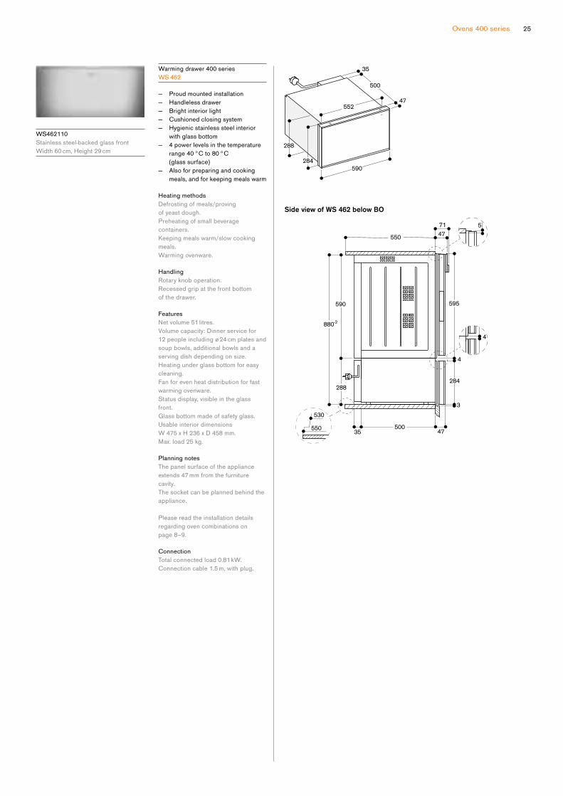
W S462110
Stainless steel-backed glass front
Width 60 cm, Height 29 cm
Warming drawer 400 series
W S 462
— Proud mounted installation
— Handleless drawer
— Bright interior light
— Cushioned closing system
— Hygienic stainless steel interior
with glass bottom
— 4 power levels in the temperature
range 40 °C to 80 °C
(glass surface)
— Also for preparing and cooking
meals, and for keeping meals warm
Heating methods
Defrosting of meals/proving
of yeast dough.
Preheating of small beverage
containers.
Keeping meals warm/slow cooking
meals.
Warming ovenware.
Handling
Rotary knob operation.
Recessed grip at the front bottom
of the drawer.
Features
Netvolume51litres.Volume capacity: Dinner service for
12 people including ø 24 cm plates and
soup bowls, additional bowls and a
serving dish depending on size.
Heating under glass bottom for easy
cleaning.
Fan for even heat distribution for fast
warming ovenware.
Status display, visible in the glass
front.
Glass bottom made of safety glass.
Usable interior dimensions
W 475 x H 236 x D 458 mm.
Max. load 25 kg.
Planning notes
The panel surface of the appliance
extends 47 mm from the furniture
cavity.
The socket can be planned behind the
appliance.
Please read the installation details
regarding oven combinations on
page 8–9.
Connection
Total connected load 0.81 kW.
Connection cable 1.5 m, with plug.
Side view of WS 462 below BO
590
880-2
595
5
288
35550
530
284
47
3
500
71
4
4
47550
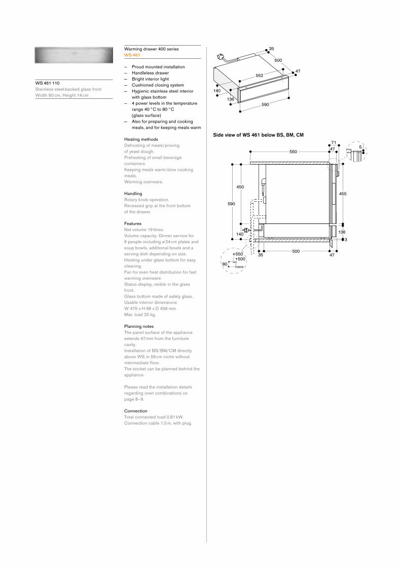
W S 461 110
Stainless steel-backed glass front
Width 60 cm, Height 14 cm
Warming drawer 400 series
W S 461
— Proud mounted installation
— Handleless drawer
— Bright interior light
— Cushioned closing system
— Hygienic stainless steel interior
with glass bottom
— 4 power levels in the temperature
range 40 °C to 80 °C
(glass surface)
— Also for preparing and cooking
meals, and for keeping meals warm
Heating methods
Defrosting of meals/proving
of yeast dough.
Preheating of small beverage
containers.
Keeping meals warm/slow cooking
meals.
Warming ovenware.
Handling
Rotary knob operation.
Recessed grip at the front bottom
of the drawer.
Features
Netvolume19litres.Volume capacity: Dinner service for
6 people including ø 24 cm plates and
soup bowls, additional bowls and a
serving dish depending on size.
Heating under glass bottom for easy
cleaning.
Fan for even heat distribution for fast
warming ovenware.
Status display, visible in the glass
front.
Glass bottom made of safety glass.
Usable interior dimensions
W 475 x H 86 x D 458 mm.
Max. load 25 kg.
Planning notes
The panel surface of the appliance
extends 47 mm from the furniture
cavity.
Installation of BS/BM/CM directly
above WS in 59 cm niche without
intermediatefloor.The socket can be planned behind the
appliance.
Please read the installation details
regarding oven combinations on
page 8–9.
Connection
Total connected load 0.81 kW.
Connection cable 1.5 m, with plug.
27Ovens 400 series
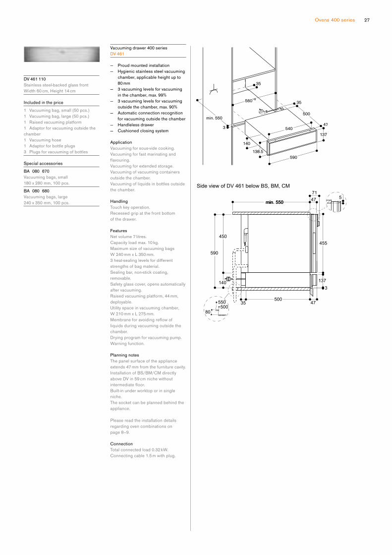
D V 461 110
Stainless steel-backed glass front
Width 60 cm, Height 14 cm
Included in the price
1 Vacuuming bag, small (50 pcs.)
1 Vacuuming bag, large (50 pcs.)
1 Raised vacuuming platform
1 Adaptor for vacuuming outside the
chamber
1 Vacuuming hose
1 Adaptor for bottle plugs
3 Plugs for vacuuming of bottles
Special accessories
BA 080 670
Vacuuming bags, small
180 x 280 mm, 100 pcs.
BA 080 680
Vacuuming bags, large
240 x 350 mm, 100 pcs.
Vacuuming drawer 400 series
D V 461
— Proud mounted installation
— Hygienic stainless steel vacuuming
chamber, applicable height up to
80 mm
— 3 vacuuming levels for vacuuming
in the chamber, max. 99%
— 3 vacuuming levels for vacuuming
outside the chamber, max. 90%
— Automatic connection recognition
for vacuuming outside the chamber
— Handleless drawer
— Cushioned closing system
Application
Vacuuming for sous-vide cooking.
Vacuuming for fast marinating and
flavouring.Vacuuming for extended storage.
Vacuuming of vacuuming containers
outside the chamber.
Vacuuming of liquids in bottles outside
the chamber.
Handling
Touch key operation.
Recessed grip at the front bottom
of the drawer.
Features
Netvolume7litres.Capacity load max. 10 kg.
Maximum size of vacuuming bags
W 240 mm x L 350 mm.
3heat-sealinglevelsfordifferentstrengths of bag material.
Sealing bar, non-stick coating,
removable.
Safety glass cover, opens automatically
after vacuuming.
Raised vacuuming platform, 44 mm,
deployable.
Utility space in vacuuming chamber,
W 210 mm x L 275 mm.
Membraneforavoidingreflowofliquids during vacuuming outside the
chamber.
Drying program for vacuuming pump.
Warning function.
Planning notes
The panel surface of the appliance
extends 47 mm from the furniture cavity.
Installation of BS/BM/CM directly
above DV in 59 cm niche without
intermediatefloor.Built-in under worktop or in single
niche.
The socket can be planned behind the
appliance.
Please read the installation details
regarding oven combinations on
page 8–9.
Connection
Total connected load 0.32 kW.
Connecting cable 1.5 m with plug.

Accessories and special accessories 400 series
B A 010 301
Triple telescopic pull-out rack
For combi-steam oven.
B A 016 105
Pull-out system
Fully extendable telescopic rails
and enamelled cast iron frame.
B A 018 105
Pull-out system
Fully extendable telescopic rails
and enamelled cast iron frame.
B A 056 115
Heating element for baking stone
and Gastronorm roaster
B A 058 115
Heating element for baking stone
and Gastronorm roaster
B A 056 133
Baking stone
Incl. baking stone support and
pizza paddle (heating element must
beorderedseparately).Notincombination with pull-out system.
B A 058 133
Baking stone
Incl. baking stone support and
pizza paddle (heating element
mustbeorderedseparately).Notincombination with pull-out system.
B A 020 380
Cooking container, non-stick,
unperforated, 40 mm deep, 5 l.
B A 020 390
Cooking container, non-stick,
perforated, 40 mm deep, 5 l.
G N 340 230
Gastronorm roaster in cast aluminium
GN2/3,height165mm,non-stickFor roasting in oven with roasting
function.
Lower and upper part can also be
used separately, height 100 and
65 mm.
For ovens with pull-out system
BA 016 or BA 018 (order heating
element separately) and Combi-steam
ovens. Includes wire rack for use with
pull-out system BA 018 / 016
Advice:
Noteveryillustratedaccessoryfitstoeveryoven.

29Ovens 400 series

31
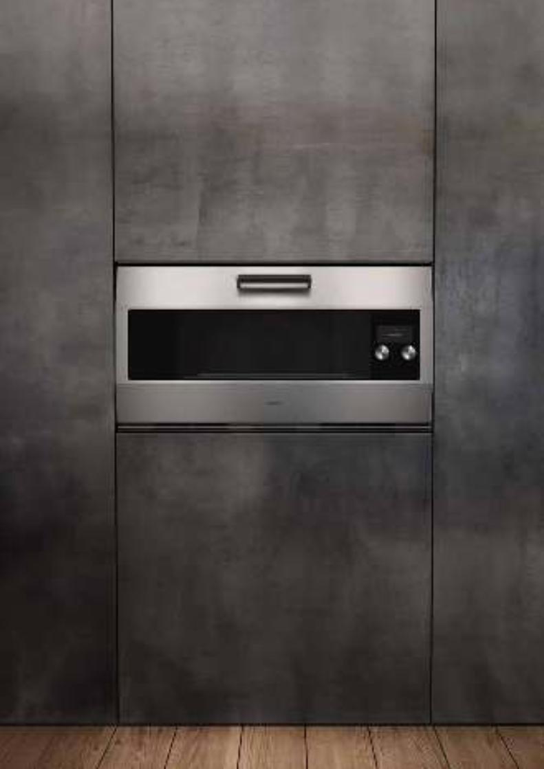
The oven EB 333
EB 333 32
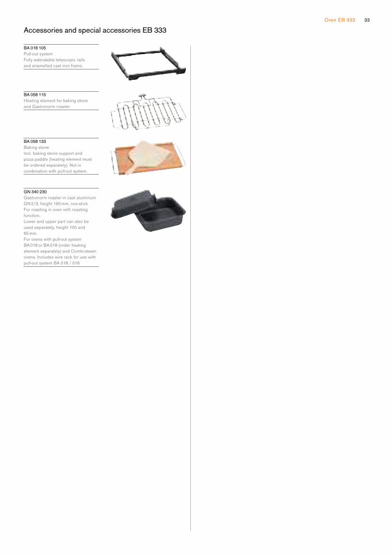
Accessories and special accessories EB 333 33

E B 333 111
Stainless steel
Width 90 cm
Included in the price
1 baking tray, enamelled pyrolysis-safe
1 rotisserie spit
1 wire rack
1 grill tray with wire rack
1 plug-in core temperature probe
Special accessories
B A 018 105
Pull-out system
Fully extendable telescopic rails and
enamelled cast iron frame.
B A 058 115
Heating element for baking stone and
Gastronorm roaster.
B A 058 133
Baking stone.
Incl. baking stone support and pizza
paddle (heating element must be
ordered separately).
Notincombinationwithpull-outsystem.
G N 340 230
Gastronorm roaster in cast aluminium.
GN2/3,height165mm,non-stick.
Oven
E B 333
— One-piece front-hinged door with
3 mm precision crafted stainless
steel front door panel
— Cushioned door opening and
closing system
— Diagonally positioned light sources
for optimal interior lighting
— Pyrolytic system
— 17 heating methods with core
temperature probe, rotisserie spit
and baking stone function
— Automatic programs
— Hot air fan rotates in both
directions for ideal heat distribution
— TFT touch display
— Panel-free appliance with control
module behind glass
— Electronic temperature control
from 30 °C to 300 °C
— Netvolume83litres
Heating methods
Hot air.
Eco hot air.
Top + bottom heat.
Top + 1/3 bottom heat.
Top heat.
1/3 top + bottom heat.
Bottom heat.
Hot air + bottom heat.
Hot air + 1/3 bottom heat.
Full surface grill + circulated air.
Full surface grill.
Compact grill.
Baking stone function.
Roaster function.
Dough proving.
Defrosting.
Keeping warm.
Handling
Rotary knob and TFT touch display
operation.
Clear text display in multiple
languages.
Option to save 50 individual recipes
(incl. core temperature probe).
Personalisation of automatic programs.
Information key with use indicators.
Front-hinged door with 90° door
opening angle.
Features
Three-point core temperature probe
withautomaticshut-offandestimationof cooking time.
40 automatic programs.
Rotisserie spit.
Baking stone socket.
Actual temperature display.
Rapid heating.
Timer functions: cooking time, cooking
time end, timer, stopwatch, long-term
timer.
60 W halogen light on the top.
2 x 10 W halogen light on the side.
Enamelled side shelf supports with
3 tray levels, pyrolysis-safe.
Home network integration for digital
services (Home Connect) either via
cableconnectionLAN(recommended)or wireless via WiFi. For further
information please check:
home-connect.com
Safety
Thermally insulated door with quintuple
glazing.
Child lock.
Safetyshut-off.Cooled housing with temperature
protection.
Cleaning
Pyrolytic system.
Gaggenau enamel.
Heated catalyser to clean the oven air.
Planning notes
The door panel surface of the
appliance extends 40 mm from the
furniture cavity.
The outer edge of the door handle
extends 90 mm from the furniture cavity.
For installation underneath cooktops:
Distance between the underside of the
cooktop and the top edge of the oven
cavity: min. 15 mm. The planning notes
for the cooktops (particularly regarding
ventilation, gas/electric connection)
must be taken into account.
To achieve the 550 mm installation
depth, the connection cable needs to
follow the slanted edge on the corner
of the housing.
The mains socket needs to be planned
outside the built-in niche.
TheLANportcanbefoundatthebackon the upper left side.
Connection
Total connected load 5.4 kW.
Plan a connection cable.
PlanaLANcable.
Socket
Measurements in mm
860475
470
40
21
890
850
480
550
90
≥ 560
≥ 20
≥ 482
≥ 2
33Oven EB 333
Accessories and special accessories EB 333
B A 018 105
Pull-out system
Fully extendable telescopic rails
and enamelled cast iron frame.
B A 058 115
Heating element for baking stone
and Gastronorm roaster
B A 058 133
Baking stone
Incl. baking stone support and
pizza paddle (heating element must
beorderedseparately).Notincombination with pull-out system.
G N 340 230
Gastronorm roaster in cast aluminium
GN2/3,height165mm,non-stickFor roasting in oven with roasting
function.
Lower and upper part can also be
used separately, height 100 and
65 mm.
For ovens with pull-out system
BA 016 or BA 018 (order heating
element separately) and Combi-steam
ovens. Includes wire rack for use with
pull-out system BA 018 / 016
35
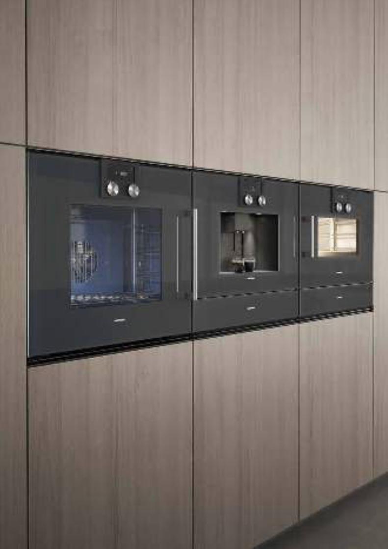
The ovens 200 series
Planning notes for ovens and oven combinations 200 series 8
Checklist for appliance combinations 200 series 36
Ovens 200 series 38
Combi-steam ovens 200 series 40
Combi-microwave ovens 200 series 43
Microwave ovens 200 series 44
Fully automatic espresso machines 200 series 45
Warming drawers 200 series 46
Vacuuming drawers 200 series 48
Accessories | special accessories 200 series 49
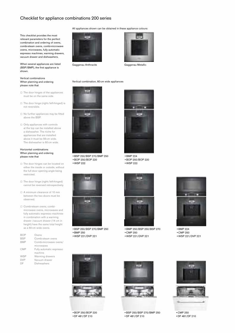
This checklist provides the most
relevant parameters for the perfect
combination and ordering of ovens,
combi-steam ovens, combi-microwave
ovens, microwaves, fully automatic
espresso machines, warming drawers,
vacuum drawer and dishwashers.
When several appliances are listed
(BSP/BMP),thefirstapplianceisshown.
Vertical combinations
When planning and ordering
please note that
□ Thedoorhingesoftheappliancesmust be on the same side.
□ Thedoorhinge(right-/left-hinged)isnot reversible.
□ Nofurtherappliancesmaybefittedabove the BSP.
□ Onlyapplianceswithcontrols at the top can be installed above
a dishwasher. The niche for
appliances that are installed
above it must be 56 cm wide.
The dishwasher is 60 cm wide.
Horizontal combinations
When planning and ordering
please note that
□ Thedoorhingescanbelocatedoneither the inside or outside, without
the full door opening angle being
restricted.
□ Thedoorhinge(right-/left-hinged)cannot be reversed retrospectively.
□ Aminimumclearanceof10mmbetween the two doors must be
observed.
□ Combi-steamovens,combi-microwave ovens, microwaves and
fully automatic espresso machines
in combination with a warming
drawer /vacuum drawer (14 cm in
height) have the same total height
as a 60 cm wide ovens.
BOP Ovens
BSP Combi-steam ovens
BMP Combi-microwave ovens/
microwaves
CMP Fully automatic espresso
machine
WSP Warming drawers
DVP Vacuum drawer
DF Dishwashers
Vertical combination, 60 cm wide appliances
•BOP 250/BOP 220
•DF 481/DF 210
•BSP 250/BSP 270/BMP 250
•DF 481/DF 210
•CMP 250
•DF 481/DF 210
•BSP 250/BSP 270/BMP 250
•BOP 250/BOP 220
•WSP 222
•BMP 224
•BOP 250/BOP 220
•WSP 222
•BSP 250/BSP 270/BMP 250
•BMP 250
•WSP 221/DVP 221
•BMP 250/BSP 250/BSP 270
•CMP 250
•WSP 221/DVP 221
•BMP 224
•CMP 250
•WSP 221/DVP 221
Gaggenau Anthracite Gaggenau Metallic
All appliances shown can be obtained in these appliance colours:
Checklist for appliance combinations 200 series
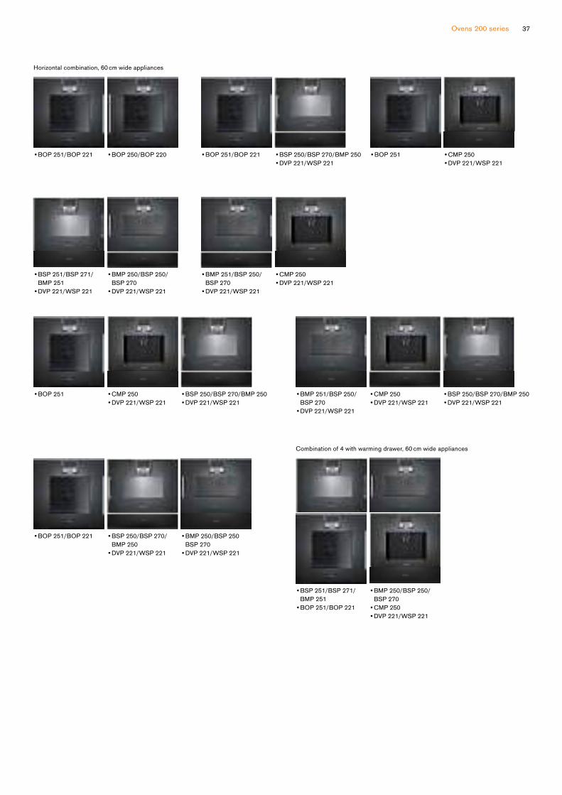
Ovens 200 series 37
Combination of 4 with warming drawer, 60 cm wide appliances
•BOP 251/BOP 221
•BOP 251
•BOP 251/BOP 221
• BSP 251/BSP 271/
BMP 251
•BOP 251/BOP 221
• BMP 251/BSP 250/
BSP 270
•DVP 221/WSP 221
• BSP 251/BSP 271/
BMP 251
•DVP 221/WSP 221
•CMP 250
•DVP 221/WSP 221
• BSP 250/BSP 270/
BMP 250
•DVP 221/WSP 221
• BMP 250/BSP 250/
BSP 270
•CMP 250
•DVP 221/WSP 221
•CMP 250
•DVP 221/WSP 221
• BMP 251/BSP 250/
BSP 270
•DVP 221/WSP 221
•BOP 250/BOP 220
• BMP 250/BSP 250/
BSP 270
•DVP 221/WSP 221
•BSP 250/BSP 270/BMP 250
•DVP 221/WSP 221
• BMP 250/BSP 250
BSP 270
•DVP 221/WSP 221
•BSP 250/BSP 270/BMP 250
•DVP 221/WSP 221
•CMP 250
•DVP 221/WSP 221
•BOP 251/BOP 221 •BSP 250/BSP 270/BMP 250
•DVP 221/WSP 221
•BOP 251 •CMP 250
•DVP 221/WSP 221
Horizontal combination, 60 cm wide appliances
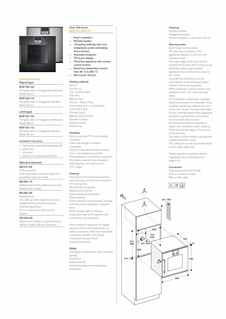
Controls at the top
Right-hinged
BO P 250 102
Full glass door in Gaggenau Anthracite
Width 60 cm
BO P 250 112
Full glass door in Gaggenau Metallic
Width 60 cm
Left-hinged
BO P 251 102
Full glass door in Gaggenau Anthracite
Width 60 cm
BO P 251 112
Full glass door in Gaggenau Metallic
Width 60 cm
Included in the price
1 baking tray, enamelled pyrolysis-safe
1 glass tray
1 wire rack
1 plug-in core temperature probe
Special accessories
B A 016 105
Pull-out system
Fully extendable telescopic rails and
enamelled cast iron frame.
B A 056 115
Heating element for baking stone and
Gastronorm roaster.
B A 056 133
Baking stone.
Incl. baking stone support and pizza
paddle (heating element must be
ordered separately).
Notincombinationwithpull-outsystem..
G N 340 230
Gastronorm roaster in cast aluminium.
GN2/3,height165mm,non-stick.
Oven 200 series
BO P 250 /BO P 251
— Flush installation
— Pyrolytic system
— 13 heating methods with core
temperature probe and baking
stone function
— Automatic programs
— TFT touch display
— Panel-free appliance with surface
control module
— Electronic temperature control
from 30 °C to 300 °C
— Netvolume76litres
Heating methods
Hot air.
Eco hot air.
Top + bottom heat.
Top heat.
Bottom heat.
Hot air + bottom heat.
Full surface grill + circulated air.
Full surface grill.
Compact grill.
Baking stone function.
Roaster function.
Dough proving.
Defrosting.
Handling
Rotary knob and TFT touch display
operation.
Clear text display in multiple
languages.
Option to save 50 individual recipes
(incl. core temperature probe).
Personalisation of automatic programs.
Information key with use indicators.
Side-opening door opens up to
110° angle.
Features
Three-point core temperature probe
withautomaticshut-offandestimationof cooking time.
40 automatic programs.
Baking stone socket.
Actual temperature display.
Rapid heating.
Timer functions: cooking time, cooking
time end, timer, stopwatch, long-term
timer.
60 W halogen light on the top.
Enamelled side shelf supports with
4 tray levels, pyrolysis-safe.
Home network integration for digital
services (Home Connect) either via
cableconnectionLAN(recommended)or wireless via WiFi. For further
information please check:
home-connect.com
Safety
Thermally insulated door with quintuple
glazing.
Child lock.
Safetyshut-off.Cooled housing with temperature
protection.
Cleaning
Pyrolytic system.
Gaggenau enamel.
Heated catalyser to clean the oven air.
Planning notes
Door hinge not reversible.
The door panel surface of the
appliance extends 21 mm from the
furniture cavity.
The outer edge of the door handle
extends 72 mm from the furniture cavity.
Necessarylateralgapbetweenappliance door and furniture panel of
min. 5 mm.
Consider the overhang, incl. the
door handle, when planning to open
drawers next to the appliance.
When planning a corner solution, pay
attention to the 110° door opening
angle.
For installation underneath cooktops:
Distance between the underside of the
cooktop and the top edge of the oven
cavity: min. 15 mm. The planning notes
for the cooktops (particularly regarding
ventilation, gas/electric connection)
must be taken into account.
To achieve the 550 mm installation
depth, the connection cable needs to
follow the slanted edge on the corner
of the housing.
The mains socket needs to be planned
outside the built-in niche.
TheLANportcanbefoundatthebackon the upper right side.
Please read the installation details
regarding oven combinations on
page 8–9.
Connection
Total connected load 3.7 kW.
Plan a connection cable.
PlanaLANcable.

Ovens 200 series 39
Controls at the top
Right-hinged
BO P 220 102
Full glass door in Gaggenau Anthracite
Width 60 cm
BO P 220 112
Full glass door in Gaggenau Metallic
Width 60 cm
Left-hinged
BO P 221 102
Full glass door in Gaggenau Anthracite
Width 60 cm
BO P 221 112
Full glass door in Gaggenau Metallic
Width 60 cm
Included in the price
1 baking tray, enamelled pyrolysis-safe
1 glass tray
1 wire rack
Special accessories
B A 016 105
Pull-out system
Fully extendable telescopic rails and
enamelled cast iron frame.
B A 056 115
Heating element for baking stone and
Gastronorm roaster.
B A 056 133
Baking stone.
Incl. baking stone support and pizza
paddle (heating element must be
ordered separately).
Notincombinationwithpull-outsystem.
G N 340 230
Gastronorm roaster in cast aluminium.
GN2/3,height165mm,non-stick.
Oven 200 series
BO P 220 /BO P 221
— Flush installation
— Pyrolytic system
— 9 heating methods, with baking
stone function
— TFT touch display
— Panel-free appliance with surface
control module
— Electronic temperature control
from 50 °C to 300 °C
— Netvolume76litres
Heating methods
Hot air.
Eco hot air.
Top + bottom heat.
Top heat.
Bottom heat.
Hot air + bottom heat.
Full surface grill + circulated air.
Full surface grill.
Baking stone function.
Handling
Rotary knob and TFT touch display
operation.
Clear text display in multiple
languages.
Option to save 50 individual recipes.
Information key with use indicators.
Side-opening door opens up to
110° angle.
Features
Baking stone socket.
Actual temperature display.
Rapid heating.
Timer functions: cooking time, cooking
time end, timer, stopwatch, long-term
timer.
60 W halogen light on the top.
Enamelled side shelf supports with
4 tray levels, pyrolysis-safe.
Home network integration for digital
services (Home Connect) either via
cableconnectionLAN(recommended)or wireless via WiFi. For further
information please check:
home-connect.com
Safety
Thermally insulated door with quintuple
glazing.
Child lock.
Safetyshut-off.Cooled housing with temperature
protection.
Cleaning
Pyrolytic system.
Gaggenau enamel.
Heated catalyser to clean the oven air.
Planning notes
Door hinge not reversible.
The door panel surface of the
appliance extends 21 mm from the
furniture cavity.
The outer edge of the door handle
extends 72 mm from the furniture
cavity.
Necessarylateralgapbetweenappliance door and furniture panel
of min. 5 mm.
Consider the overhang, incl. the
door handle, when planning to open
drawers next to the appliance.
When planning a corner solution, pay
attention to the 110° door opening
angle.
For installation underneath cooktops:
Distance between the underside of the
cooktop and the top edge of the oven
cavity: min. 15 mm.
The planning notes for the cooktops
(particularly regarding ventilation, gas/
electric connection) must be taken into
account.
To achieve the 550 mm installation
depth, the connection cable needs to
follow the slanted edge on the corner
of the housing.
The mains socket needs to be planned
outside the built-in niche.
TheLANportcanbefoundatthebackon the upper right side.
Please read the installation details
regarding oven combinations on
page 8–9.
Connection
Total connected load 3.7 kW.
Plan a connection cable.
PlanaLANcable.
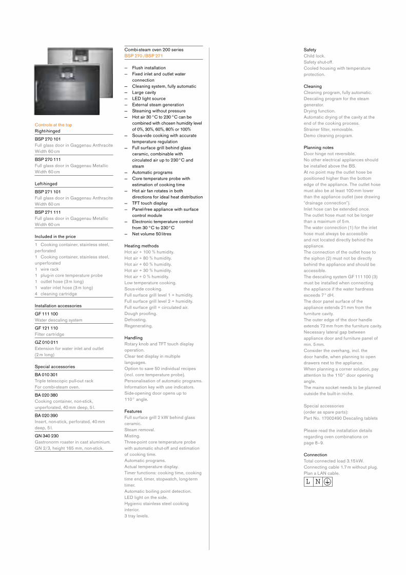
Controls at the top
Right-hinged
BS P 270 101
Full glass door in Gaggenau Anthracite
Width 60 cm
BS P 270 111
Full glass door in Gaggenau Metallic
Width 60 cm
Left-hinged
BS P 271 101
Full glass door in Gaggenau Anthracite
Width 60 cm
BS P 271 111
Full glass door in Gaggenau Metallic
Width 60 cm
Included in the price
1 Cooking container, stainless steel,
perforated
1 Cooking container, stainless steel,
unperforated
1 wire rack
1 plug-in core temperature probe
1 outlet hose (3 m long)
1 water inlet hose (3 m long)
4 cleaning cartridge
Installation accessories
G F 111 100
Water descaling system
G F 121 110
Filter cartridge
G Z 010 011
Extension for water inlet and outlet
(2 m long)
Special accessories
B A 010 301
Triple telescopic pull-out rack
For combi-steam oven.
B A 020 380
Cooking container, non-stick,
unperforated, 40 mm deep, 5 l.
B A 020 390
Insert, non-stick, perforated, 40 mm
deep, 5 l.
G N 340 230
Gastronorm roaster in cast aluminium.
GN2/3,height165mm,non-stick.
Combi-steam oven 200 series
BS P 270 /BS P 271
— Flush installation
— Fixed inlet and outlet water
connection
— Cleaning system, fully automatic
— Large cavity
— LED light source
— External steam generation
— Steaming without pressure
— Hot air 30 °C to 230 °C can be
combined with chosen humidity level
of 0%, 30%, 60%, 80% or 100%
— Sous-vide cooking with accurate
temperature regulation
— Full surface grill behind glass
ceramic, combinable with
circulated air up to 230°C and
steam
— Automatic programs
— Core temperature probe with
estimation of cooking time
— Hot air fan rotates in both
directions for ideal heat distribution
— TFT touch display
— Panel-free appliance with surface
control module
— Electronic temperature control
from 30 °C to 230°C
— Netvolume50litres
Heating methods
Hot air + 100 % humidity.
Hot air + 80 % humidity.
Hot air + 60 % humidity.
Hot air + 30 % humidity.
Hot air + 0 % humidity.
Low temperature cooking.
Sous-vide cooking.
Full surface grill level 1 + humidity.
Full surface grill level 2 + humidity.
Full surface grill + circulated air.
Doughproofing. Defrosting.
Regenerating.
Handling
Rotary knob and TFT touch display
operation.
Clear text display in multiple
languages.
Option to save 50 individual recipes
(incl. core temperature probe).
Personalisation of automatic programs.
Information key with use indicators.
Side-opening door opens up to
110° angle.
Features
Full surface grill 2 kW behind glass
ceramic.
Steam removal.
Misting.
Three-point core temperature probe
withautomaticshut-offandestimationof cooking time.
Automatic programs.
Actual temperature display.
Timer functions: cooking time, cooking
time end, timer, stopwatch, long-term
timer.
Automatic boiling point detection.
LED light on the side.
Hygienic stainless steel cooking
interior.
3 tray levels.
Safety
Child lock.
Safetyshut-off.Cooled housing with temperature
protection.
Cleaning
Cleaning program, fully automatic.
Descaling program for the steam
generator.
Drying function.
Automatic drying of the cavity at the
end of the cooking process.
Strainerfilter,removable.Demo cleaning program.
Planning notes
Door hinge not reversible.
Nootherelectricalappliancesshouldbe installed above the BS.
At no point may the outlet hose be
positioned higher than the bottom
edge of the appliance. The outlet hose
must also be at least 100 mm lower
than the appliance outlet (see drawing
"drainage connection").
Inlet hose can be extended once.
The outlet hose must not be longer
than a maximum of 5 m.
The water connection (1) for the inlet
hose must always be accessible
and not located directly behind the
appliance.
The connection of the outlet hose to
the siphon (2) must not be directly
behind the appliance and should be
accessible.
The descaling system GF 111 100 (3)
must be installed when connecting
the appliance if the water hardness
exceeds 7° dH.
The door panel surface of the
appliance extends 21 mm from the
furniture cavity.
The outer edge of the door handle
extends 72 mm from the furniture cavity.
Necessarylateralgapbetweenappliance door and furniture panel of
min. 5 mm.
Consider the overhang, incl. the
door handle, when planning to open
drawers next to the appliance.
When planning a corner solution, pay
attention to the 110° door opening
angle.
The mains socket needs to be planned
outside the built-in niche.
Special accessories
(order as spare parts):
PartNo.17002490Descalingtablets
Please read the installation details
regarding oven combinations on
page 8–9.
Connection
Total connected load 3.15 kW.
Connecting cable 1.7 m without plug.
PlanaLANcable.
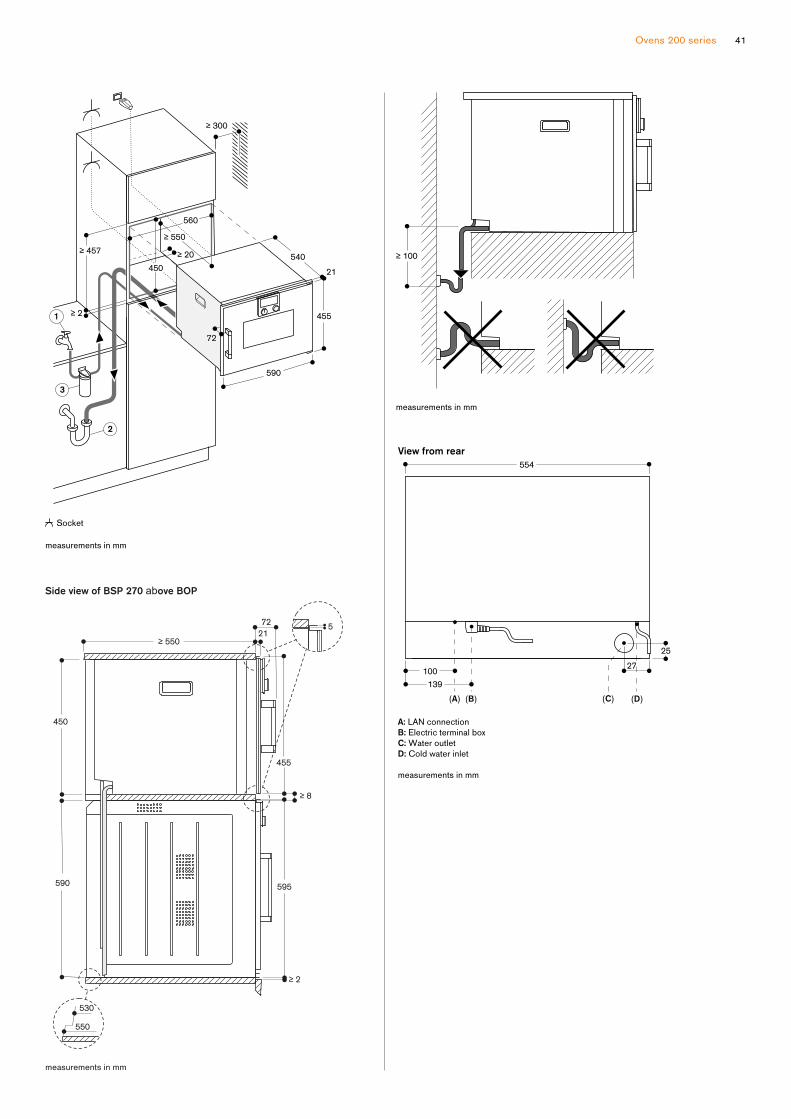
Ovens 200 series 41

Controls at the top
Right-hinged
BS P 250 101
Full glass door in Gaggenau Anthracite
Width 60 cm
BS P 250 111
Full glass door in Gaggenau Metallic
Width 60 cm
Left-hinged
BS P 251 101
Full glass door in Gaggenau Anthracite
Width 60 cm
BS P 251 111
Full glass door in Gaggenau Metallic
Width 60 cm
Included in the price
1 cooking container, stainless steel,
perforated
1 cooking container, stainless steel,
unperforated
1 wire rack
1 plug-in core temperature probe
Special accessories
B A 010 301
Triple telescopic pull-out rack
For combi-steam oven.
B A 020 380
Cooking container, non-stick,
unperforated, 40 mm deep, 5 l.
B A 020 390
Insert, non-stick, perforated, 40 mm
deep, 5 l.
G N 340 230
Gastronorm roaster in cast aluminium.
GN2/3,height165mm,non-stick.
Combi-steam oven 200 series
BS P 250 /BS P 251
— Flush installation
— Water tank for fresh and waste
water
— Large cavity
— LED light source
— External steam generation
— Steaming without pressure
— Hot air 30 °C to 230 °C can be
combined with chosen humidity level
of 0%, 30%, 60%, 80% or 100%
— Sous-vide cooking with accurate
temperature regulation
— Full surface grill behind glass
ceramic, combinable with
circulated air up to 230°C and
steam
— Automatic programs
— Core temperature probe with
estimation of cooking time
— Hot air fan rotates in both
directions for ideal heat distribution
— TFT touch display
— Panel-free appliance with surface
control module
— Electronic temperature control
from 30 °C to 230 °C
— Netvolume50litres
Heating methods
Hot air + 100 % humidity.
Hot air + 80 % humidity.
Hot air + 60 % humidity.
Hot air + 30 % humidity.
Hot air + 0 % humidity.
Low temperature cooking.
Sous-vide cooking.
Full surface grill level 1 + humidity.
Full surface grill level 2 + humidity.
Full surface grill + circulated air.
Doughproofing. Defrosting.
Regenerating.
Handling
Rotary knob and TFT touch display
operation.
Clear text display in multiple
languages.
Option to save 50 individual recipes
(incl. core temperature probe).
Personalisation of automatic programs.
Information key with use indicators.
Side-opening door opens up to
110° angle.
Features
Full surface grill 2 kW behind glass
ceramic.
2 removable 1.7 litre water tanks.
Water level warning.
Three-point core temperature probe
withautomaticshut-offandestimationof cooking time.
Automatic programs.
Actual temperature display.
Timer functions: cooking time, cooking
time end, timer, stopwatch, long-term
timer.
Automatic boiling point detection.
LED light on the side.
Hygienic stainless steel cooking
interior.
3 tray levels.
Safety
Child lock.
Safetyshut-off.Cooled housing with temperature
protection.
Cleaning
Cleaning aid.
Descaling program for the steam
generator.
Drying function.
Automatic drying of the cavity at the end
of the cooking process.
Water tank, dishwasher-safe.
Greasefilter,dishwasher-safe.Strainerfilter,removable.
Planning notes
Door hinge not reversible.
Nootherelectricalappliancesshouldbe installed above the BS.
The door panel surface of the appliance
extends 21 mm from the furniture cavity.
The outer edge of the door handle
extends 72 mm from the furniture cavity.
Necessarylateralgapbetweenappliance door and furniture panel of
min. 5 mm.
Consider the overhang, incl. the
door handle, when planning to open
drawers next to the appliance.
When planning a corner solution, pay
attention to the 110° door opening
angle.
The mains socket needs to be planned
outside the built-in niche.
TheLANportcanbefoundatthebackon the lower left side.
Special accessories
(order as spare parts):
PartNo.17002490Descalingtablets
Please read the installation details
regarding oven combinations on
page 8–9.
Connection
Total connected load 3.15 kW.
Connecting cable 1.7m without plug.
PlanaLANcable.
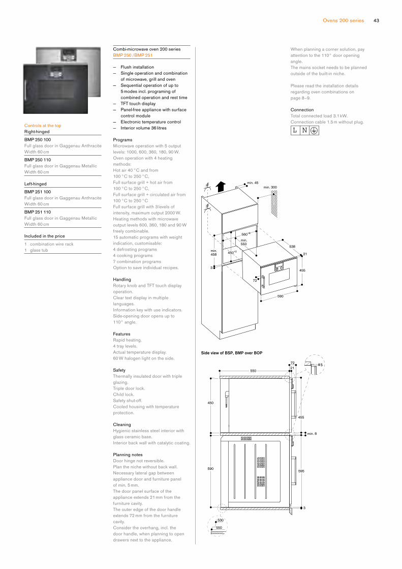
Ovens 200 series 43
Controls at the top
Right-hinged
BM P 250 100
Full glass door in Gaggenau Anthracite
Width 60 cm
BM P 250 110
Full glass door in Gaggenau Metallic
Width 60 cm
Left-hinged
BM P 251 100
Full glass door in Gaggenau Anthracite
Width 60 cm
BM P 251 110
Full glass door in Gaggenau Metallic
Width 60 cm
Included in the price
1 combination wire rack
1 glass tub
Combi-microwave oven 200 series
BM P 250 /BM P 251
— Flush installation
— Single operation and combination
of microwave, grill and oven
— Sequential operation of up to
5 modes incl. programing of
combined operation and rest time
— TFT touch display
— Panel-free appliance with surface
control module
— Electronic temperature control
— Interior volume 36 litres
Programs
Microwave operation with 5 output
levels: 1000, 600, 360, 180, 90 W.
Oven operation with 4 heating
methods:
Hot air 40 °C and from
100 °C to 250 °C,
Full surface grill + hot air from
100 °C to 250 °C,
Full surface grill + circulated air from
100 °C to 250 °C
Full surface grill with 3 levels of
intensity, maximum output 2000 W.
Heating methods with microwave
output levels 600, 360, 180 and 90 W
freely combinable.
15 automatic programs with weight
indication, customisable:
4 defrosting programs
4 cooking programs
7 combination programs
Option to save individual recipes.
Handling
Rotary knob and TFT touch display
operation.
Clear text display in multiple
languages.
Information key with use indicators.
Side-opening door opens up to
110° angle.
Features
Rapid heating.
4 tray levels.
Actual temperature display.
60 W halogen light on the side.
Safety
Thermally insulated door with triple
glazing.
Triple door lock.
Child lock.
Safetyshut-off.Cooled housing with temperature
protection.
Cleaning
Hygienic stainless steel interior with
glass ceramic base.
Interior back wall with catalytic coating.
Planning notes
Door hinge not reversible.
Plan the niche without back wall.
Necessarylateralgapbetweenappliance door and furniture panel
of min. 5 mm.
The door panel surface of the
appliance extends 21 mm from the
furniture cavity.
The outer edge of the door handle
extends 72 mm from the furniture
cavity.
Consider the overhang, incl. the
door handle, when planning to open
drawers next to the appliance.
When planning a corner solution, pay
attention to the 110° door opening
angle.
The mains socket needs to be planned
outside of the built-in niche.
Please read the installation details
regarding oven combinations on
page 8–9.
Connection
Total connected load 3.1 kW.
Connection cable 1.5 m without plug.

Controls at the bottom
Right-hinged
BM P 224 100
Full glass door in Gaggenau Anthracite
Width 60 cm
BM P 224 110
Full glass door in Gaggenau Metallic
Width 60 cm
Left-hinged
BM P 225 100
Full glass door in Gaggenau Anthracite
Width 60 cm
BM P 225 110
Full glass door in Gaggenau Metallic
Width 60 cm
Included in the price
1 glass tray
1 wire rack
Microwave oven 200 series
BM P 224 /BM P 225
— Flush installation
— Handleless door / automatic door
opening
— Single operation and combination
of microwave and grill
— Sequential operation of up to
5 modes incl. programing of
combined operation and rest time
— TFT touch display
— Electronic temperature control
— Interior volume 21 litres
Programs
Microwave operation with 5 output
levels: 900, 600, 360, 180, 90 W.
Full surface grill with 3 levels of
intensity, maximum output 1300 W.
Full surface grill with microwave output
levels 360, 180 and 90 W combinable.
10 automatic programs with weight
indication:
3 defrosting programs
4 cooking programs
3 combination programs
Option to save individual recipes.
Handling
Automatic door opening.
Rotary knob and TFT touch display
operation.
Clear text display in multiple
languages.
Information key with use indicators.
Side-opening door opens up to
110° angle.
Features
Actual temperature display.
25 W interior light.
Hygienic stainless steel interior with
glass ceramic base.
Safety
Thermally insulated door with double
glazing.
Triple door lock.
Child lock.
Safetyshut-off.Cooled housing with temperature
protection.
Planning notes
Door hinge not reversible.
Minimum installation height 85 cm
(top edge of niche bottom).
Height-adjustable feet.
Installation of BMP above BOP with
intermediate shelf.
Necessarylateralgapbetweenappliance door and furniture panel of
min. 5 mm.
The door panel surface of the
appliance extends 21 mm from the
furniture cavity.
When planning a corner solution, pay
attention to the 90° door opening
angle.
Please read the installation details
regarding oven combinations on
page 8–9.
Connection
Total connected load 2.0 kW.
Connection cable 1.7 m, with plug.
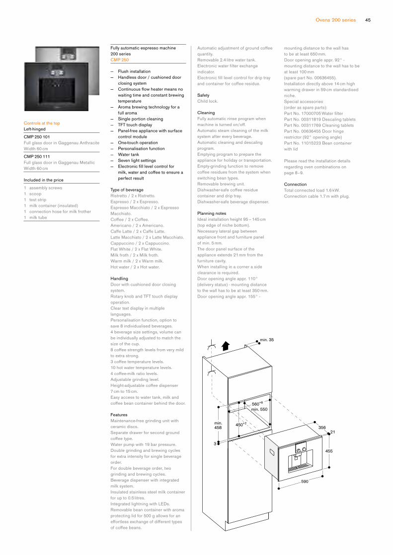
Ovens 200 series 45
Controls at the top
Left-hinged
CM P 250 101
Full glass door in Gaggenau Anthracite
Width 60 cm
CM P 250 111
Full glass door in Gaggenau Metallic
Width 60 cm
Included in the price
1 assembly screws
1 scoop
1 test strip
1 milk container (insulated)
1 connection hose for milk frother
1 milk tube
Fully automatic espresso machine
200 series
CM P 250
— Flush installation
— Handless door / cushioned door
closing system
— Continuousflowheatermeansnowaiting time and constant brewing
temperature
— Aroma brewing technology for a
full aroma
— Single portion cleaning
— TFT touch display
— Panel-free appliance with surface
control module
— One-touch operation
— Personalisation function
— Water tank
— Seven light settings
— Electronicfilllevelcontrolformilk,waterandcoffeetoensureaperfect result
Type of beverage
Ristretto / 2 x Ristretto.
Espresso / 2 x Espresso.
Espresso Macchiato / 2 x Espresso
Macchiato.
Coffee/2xCoffee. Americano / 2 x Americano.
CaffeLatte/2xCaffeLatte. Latte Macchiato / 2 x Latte Macchiato.
Cappuccino / 2 x Cappuccino.
Flat White / 2 x Flat White.
Milk froth / 2 x Milk froth.
Warm milk / 2 x Warm milk.
Hot water / 2 x Hot water.
Handling
Door with cushioned door closing
system.
Rotary knob and TFT touch display
operation.
Clear text display in multiple
languages.
Personalisation function, option to
save 8 individualised beverages.
4 beverage size settings, volume can
be individually adjusted to match the
size of the cup.
8coffeestrengthlevelsfromverymildto extra strong.
3coffeetemperaturelevels.10 hot water temperature levels.
4coffee-milkratiolevels.Adjustable grinding level.
Height-adjustablecoffeedispenser7 cm to 15 cm.
Easy access to water tank, milk and
coffeebeancontainerbehindthedoor.
Features
Maintenance-free grinding unit with
ceramic discs.
Separate drawer for second ground
coffeetype.Water pump with 19 bar pressure.
Double grinding and brewing cycles
for extra intensity for single beverage
order.
For double beverage order, two
grinding and brewing cycles.
Beverage dispenser with integrated
milk system.
Insulated stainless steel milk container
for up to 0.5 litres.
Integrated lightning with LEDs.
Removable bean container with aroma
protecting lid for 500 g allows for an
effortlessexchangeofdifferenttypesofcoffeebeans.
Automaticadjustmentofgroundcoffeequantity.
Removable 2.4 litre water tank.
Electronicwaterfilterexchangeindicator.
Electronicfilllevelcontrolfordriptrayandcontainerforcoffeeresidue.
Safety
Child lock.
Cleaning
Fully automatic rinse program when
machineisturnedon/off.Automatic steam cleaning of the milk
system after every beverage.
Automatic cleaning and descaling
program.
Emptying program to prepare the
appliance for holiday or transportation.
Empty-grinding function to remove
coffeeresiduesfromthesystemwhenswitching bean types.
Removable brewing unit.
Dishwasher-safecoffeeresiduecontainer and drip tray.
Dishwasher-safe beverage dispenser.
Planning notes
Ideal installation height 95 – 145 cm
(top edge of niche bottom).
Necessarylateralgapbetweenappliance front and furniture panel
of min. 5 mm.
The door panel surface of the
appliance extends 21 mm from the
furniture cavity.
When installing in a corner a side
clearance is required.
Door opening angle appr. 110°
(delivery status) - mounting distance
to the wall has to be at least 350 mm.
Door opening angle appr. 155° -
mounting distance to the wall has
to be at least 650 mm.
Door opening angle appr. 92° -
mounting distance to the wall has to be
at least 100 mm
(sparepartNo.00636455).Installation directly above 14 cm high
warming drawer in 59 cm standardised
niche.
Special accessories
(order as spare parts):
PartNo.17000705Waterfilter PartNo.00311819Descalingtablets
PartNo.00311769Cleaningtablets
PartNo.00636455Doorhingerestrictor (92° opening angle)
PartNo.11015223Beancontainerwith lid
Please read the installation details
regarding oven combinations on
page 8–9.
Connection
Total connected load 1.6 kW.
Connection cable 1.7 m with plug.
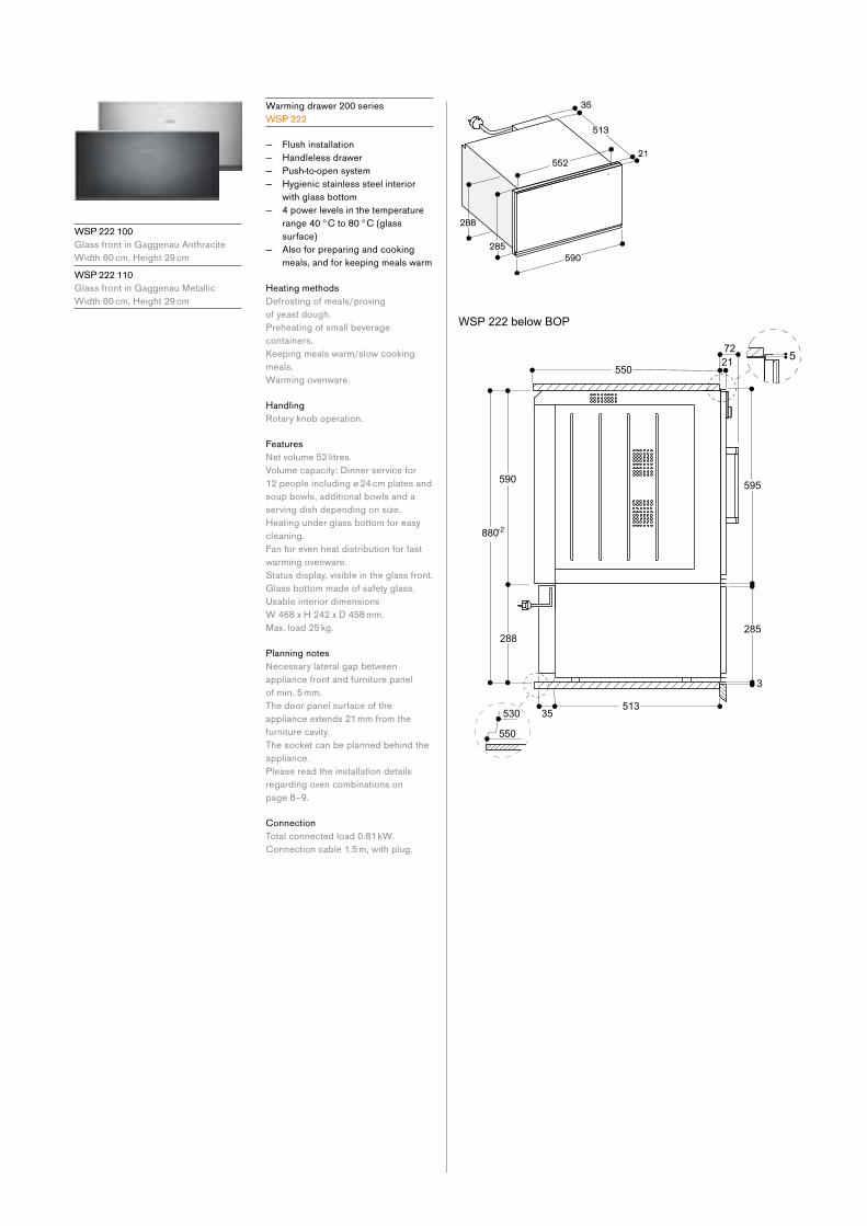
Warming drawer 200 series
WS P 222
— Flush installation
— Handleless drawer
— Push-to-open system
— Hygienic stainless steel interior
with glass bottom
— 4 power levels in the temperature
range 40 °C to 80 °C (glass
surface)
— Also for preparing and cooking
meals, and for keeping meals warm
Heating methods
Defrosting of meals/proving
of yeast dough.
Preheating of small beverage
containers.
Keeping meals warm/slow cooking
meals.
Warming ovenware.
Handling
Rotary knob operation.
Features
Netvolume52litres.Volume capacity: Dinner service for
12 people including ø 24 cm plates and
soup bowls, additional bowls and a
serving dish depending on size.
Heating under glass bottom for easy
cleaning.
Fan for even heat distribution for fast
warming ovenware.
Status display, visible in the glass front.
Glass bottom made of safety glass.
Usable interior dimensions
W 468 x H 242 x D 458 mm.
Max. load 25 kg.
Planning notes
Necessarylateralgapbetweenappliance front and furniture panel
of min. 5 mm.
The door panel surface of the
appliance extends 21 mm from the
furniture cavity.
The socket can be planned behind the
appliance.
Please read the installation details
regarding oven combinations on
page 8–9.
Connection
Total connected load 0.81 kW.
Connection cable 1.5 m, with plug.
WS P 222 100
Glass front in Gaggenau Anthracite
Width 60 cm, Height 29 cm
WS P 222 110
Glass front in Gaggenau Metallic
Width 60 cm, Height 29 cm

Ovens 200 series 47
WS P 221 100
Glass front in Gaggenau Anthracite
Width 60 cm, Height 14 cm
WS P 221 110
Glass front in Gaggenau Metallic
Width 60 cm, Height 14 cm
Warming drawer 200 series
WS P 221
— Flush installation
— Handleless drawer
— Push-to-open system
— Hygienic stainless steel interior
with glass bottom
— 4 power levels in the temperature
range 40 °C to 80 °C (glass
surface)
— Also for preparing and cooking
meals, and for keeping meals warm
Heating methods
Defrosting of meals/proving
of yeast dough.
Preheating of small beverage
containers.
Keeping meals warm/slow cooking
meals.
Warming ovenware.
Handling
Rotary knob operation.
Features
Netvolume20litres.Volume capacity: Dinner service for
6 people including ø 24 cm plates and
soup bowls, additional bowls and a
serving dish depending on size.
Heating under glass bottom for easy
cleaning.
Fan for even heat distribution for fast
warming ovenware.
Status display, visible in the glass front.
Glass bottom made of safety glass.
Usable interior dimensions
W 468 x H 92 x D 458 mm.
Max. load 25 kg.
Planning notes
Necessarylateralgapbetweenappliance front and furniture panel
of min. 5 mm.
The door panel surface of the
appliance extends 21 mm from the
furniture cavity.
Installation of BSP/BMP/CMP directly
above WSP in 59 cm niche without
intermediatefloor.The socket can be planned behind the
appliance.
Please read the installation details
regarding oven combinations on
page 8–9.
Connection
Total connected load 0.81 kW.
Connection cable 1.5 m with plug.

DV P 221 100
Glass front in Gaggenau Anthracite
Width 60 cm, Height 14 cm
DV P 221 110
Glass front in Gaggenau Metallic
Width 60 cm, Height 14 cm
Included in the price
1 vacuuming bag, small (50 pcs.)
1 vacuuming bag, large (50 pcs.)
1 raised vacuuming platform
1 adaptor for vacuuming outside
the chamber
1 vacuuming hose
1 adaptor for bottle plugs
3 plugs for vacuuming of bottles
Special accessories
BA 080 670
Vacuuming bags, small
180 x 280 mm, 100 pcs.
BA 080 680
Vacuuming bags, large
240 x 350 mm, 100 pcs.
Vacuuming drawer 200 series
DV P 221
— Flush installation
— Handleless drawer
— Push-to-open system
— Hygienic stainless steel vacuuming
chamber, applicable height up to
80 mm
— Three vacuuming levels for
vacuuming in the chamber, max.
99%
— Three vacuuming levels for
vacuuming outside the chamber,
max. 90%
— Automatic connection recognition
for vacuuming outside the chamber
Application
Vacuuming for sous-vide cooking.
Vacuuming for fast marinating and
flavouring.Vacuuming for extended storage.
Vacuuming of vacuuming containers
outside the chamber.
Vacuuming of liquids in bottles outside
the chamber.
Handling
Touch key operation.
Features
Netvolume7litres.Capacity load max. 10 kg.
Maximum size of vacuuming bags
W 240 mm x L 350 mm.
3heat-sealinglevelsfordifferentstrengths of bag material.
Sealing bar, non-stick coating,
removable.
Safety glass cover, opens automatically
after vacuuming.
Raised vacuuming platform, 44 mm,
deployable.
Utility space in vacuuming chamber,
W 210 mm x L 275 mm.
Membraneforavoidingreflowofliquids during vacuuming outside the
chamber.
Drying program for vacuuming pump.
Warning function.
Planning notes
Necessarylateralgapbetweenappliance front and furniture panel
of min. 5 mm.
The panel surface of the appliance
extends 21 mm from the furniture cavity.
Installation of BS/BM/CM directly
above DV in 59 cm niche without
intermediatefloor.Built-in under worktop or in single
niche.
The socket can be planned behind the
appliance.
Please read the installation details
regarding oven combinations on
page 8–9.
Connection
Total connected load 0.32 kW.
Connecting cable 1.5 m with plug.
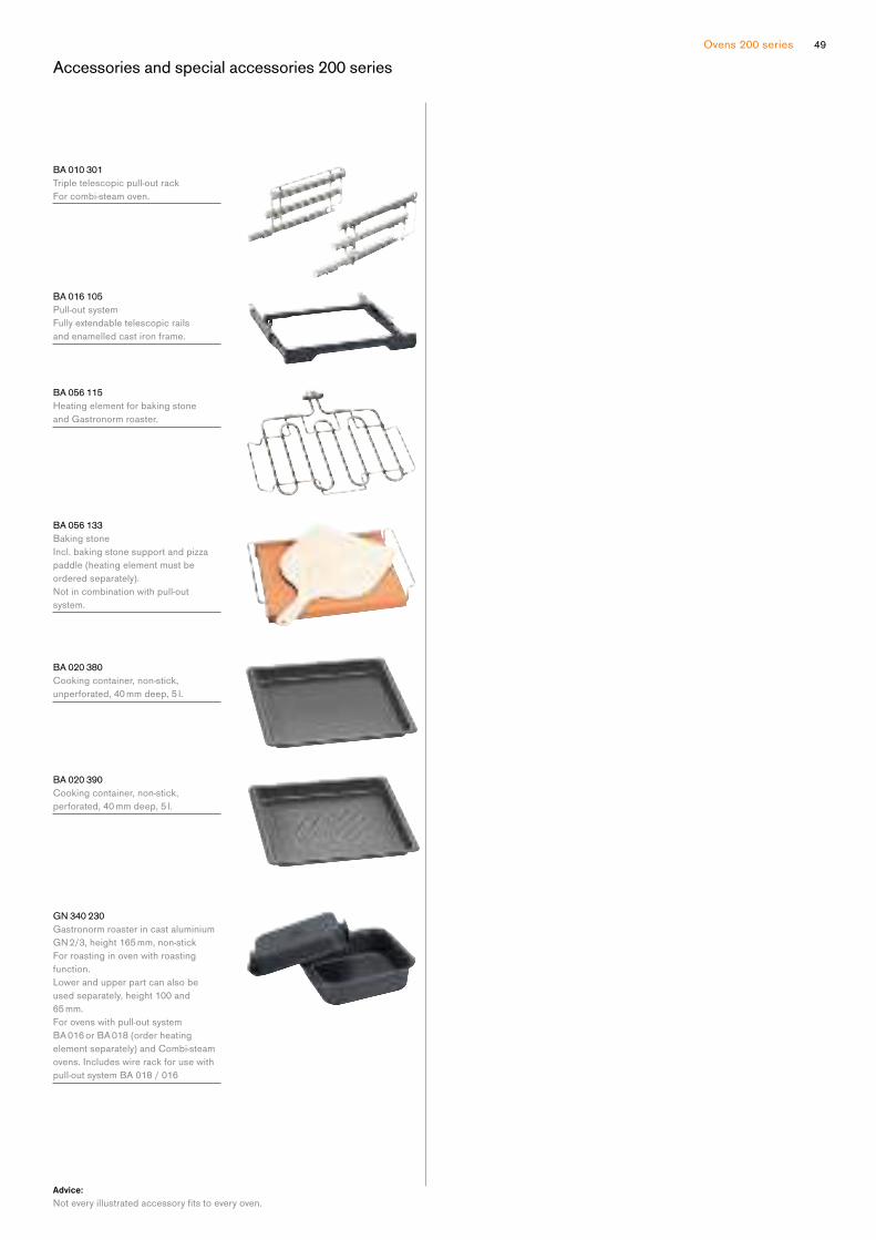
Ovens 200 series 49
Accessories and special accessories 200 series
B A 010 301
Triple telescopic pull-out rack
For combi-steam oven.
B A 016 105
Pull-out system
Fully extendable telescopic rails
and enamelled cast iron frame.
B A 056 115
Heating element for baking stone
and Gastronorm roaster.
B A 056 133
Baking stone
Incl. baking stone support and pizza
paddle (heating element must be
ordered separately).
Notincombinationwithpull-outsystem.
B A 020 380
Cooking container, non-stick,
unperforated, 40 mm deep, 5 l.
B A 020 390
Cooking container, non-stick,
perforated, 40 mm deep, 5 l.
G N 340 230
Gastronorm roaster in cast aluminium
GN2/3,height165mm,non-stickFor roasting in oven with roasting
function.
Lower and upper part can also be
used separately, height 100 and
65 mm.
For ovens with pull-out system
BA 016 or BA 018 (order heating
element separately) and Combi-steam
ovens. Includes wire rack for use with
pull-out system BA 018 / 016
Advice:
Noteveryillustratedaccessoryfitstoeveryoven.
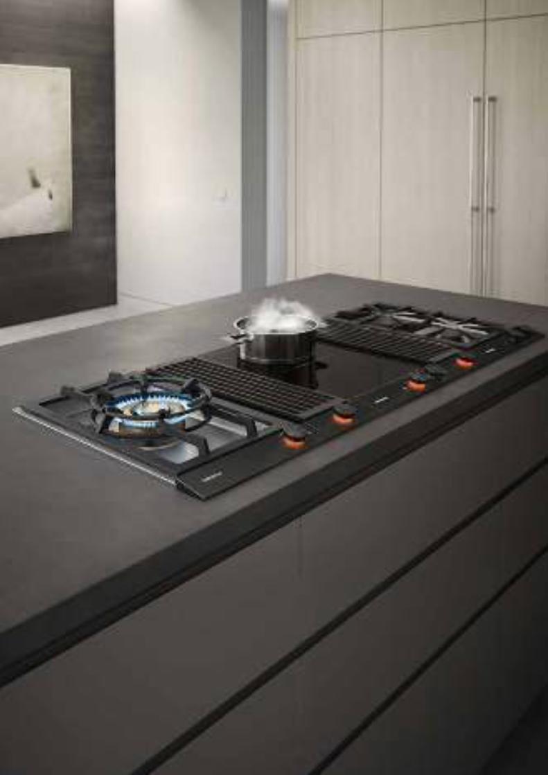
51
The Vario cooktops
Vario cooktops 400 series 52
Vario downdraft ventilation 400 series 68
Table ventilation 400 series 72
Cut-out dimensions for appliance combinations in the 400 series 74
Installation with appliance cover and filler strip in the 400 series 79
Vario cooktops 200 series 80
Vario downdraft ventilation 200 series 87
Cut-out dimensions for appliance combinations in the 200 series 88
Accessories | special accessories 90
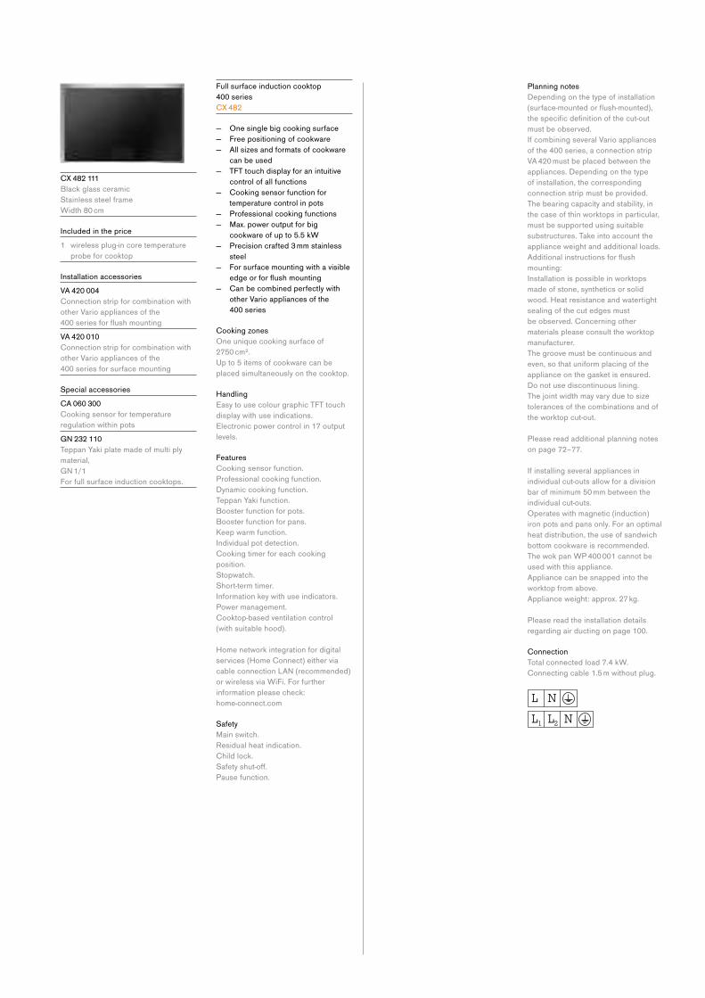
C X 482 111
Black glass ceramic
Stainless steel frame
Width 80 cm
Included in the price
1 wireless plug-in core temperature
probe for cooktop
Installation accessories
V A 420 004
Connection strip for combination with
other Vario appliances of the
400seriesforflushmountingV A 420 010
Connection strip for combination with
other Vario appliances of the
400 series for surface mounting
Special accessories
C A 060 300
Cooking sensor for temperature
regulation within pots
G N 232 110
Teppan Yaki plate made of multi ply
material,
GN1/1
For full surface induction cooktops.
Full surface induction cooktop
400 series
CX 482
— One single big cooking surface
— Free positioning of cookware
— All sizes and formats of cookware
can be used
— TFT touch display for an intuitive
control of all functions
— Cooking sensor function for
temperature control in pots
— Professional cooking functions
— Max. power output for big
cookware of up to 5.5 kW
— Precision crafted 3 mm stainless
steel
— For surface mounting with a visible
edgeorforflushmounting — Can be combined perfectly with
other Vario appliances of the
400 series
Cooking zones
One unique cooking surface of
2750 cm².
Up to 5 items of cookware can be
placed simultaneously on the cooktop.
Handling
Easy to use colour graphic TFT touch
display with use indications.
Electronic power control in 17 output
levels.
Features
Cooking sensor function.
Professional cooking function.
Dynamic cooking function.
Teppan Yaki function.
Booster function for pots.
Booster function for pans.
Keep warm function.
Individual pot detection.
Cooking timer for each cooking
position.
Stopwatch.
Short-term timer.
Information key with use indicators.
Power management.
Cooktop-based ventilation control
(with suitable hood).
Home network integration for digital
services (Home Connect) either via
cableconnectionLAN(recommended)or wireless via WiFi. For further
information please check:
home-connect.com
Safety
Main switch.
Residual heat indication.
Child lock.
Safetyshut-off.Pause function.
Planning notes
Depending on the type of installation
(surface-mountedorflush-mounted),thespecificdefinitionofthecut-outmust be observed.
If combining several Vario appliances
of the 400 series, a connection strip
VA 420 must be placed between the
appliances. Depending on the type
of installation, the corresponding
connection strip must be provided.
The bearing capacity and stability, in
the case of thin worktops in particular,
must be supported using suitable
substructures. Take into account the
appliance weight and additional loads.
Additionalinstructionsforflushmounting:
Installation is possible in worktops
made of stone, synthetics or solid
wood. Heat resistance and watertight
sealing of the cut edges must
be observed. Concerning other
materials please consult the worktop
manufacturer.
The groove must be continuous and
even, so that uniform placing of the
appliance on the gasket is ensured.
Do not use discontinuous lining.
The joint width may vary due to size
tolerances of the combinations and of
the worktop cut-out.
Please read additional planning notes
on page 72–77.
If installing several appliances in
individual cut-outs allow for a division
bar of minimum 50 mm between the
individual cut-outs.
Operates with magnetic (induction)
iron pots and pans only. For an optimal
heat distribution, the use of sandwich
bottom cookware is recommended.
The wok pan WP 400 001 cannot be
used with this appliance.
Appliance can be snapped into the
worktop from above.
Appliance weight: approx. 27 kg.
Please read the installation details
regarding air ducting on page 100.
Connection
Total connected load 7.4 kW.
Connecting cable 1.5 m without plug.

53Vario cooktops
Cross-section
A: 3.5-0.5
B: Fill with silicone
measurements in mm
492±1
524+1
2 2
520 (B)
(A)
measurements in mm
492±1
784±1
520804
653
≥ 50 ≥ 70
90°
R 3
1500
A: 3.5-0.5
measurements in mm
(A)
90°
492±1 524+1
+1
808+1
784±1
520804
1500
68
≥ 50 ≥ 70
3
R 3
R 4
View from above
measurements in mm
524+1
492±1
808+1
784±1
R 4+1
R 3
Longitudinal section
A: 3.5-0.5
B: Fill with silicone
measurements in mm
(B)
(A)
784±1
804
2 2
808+1
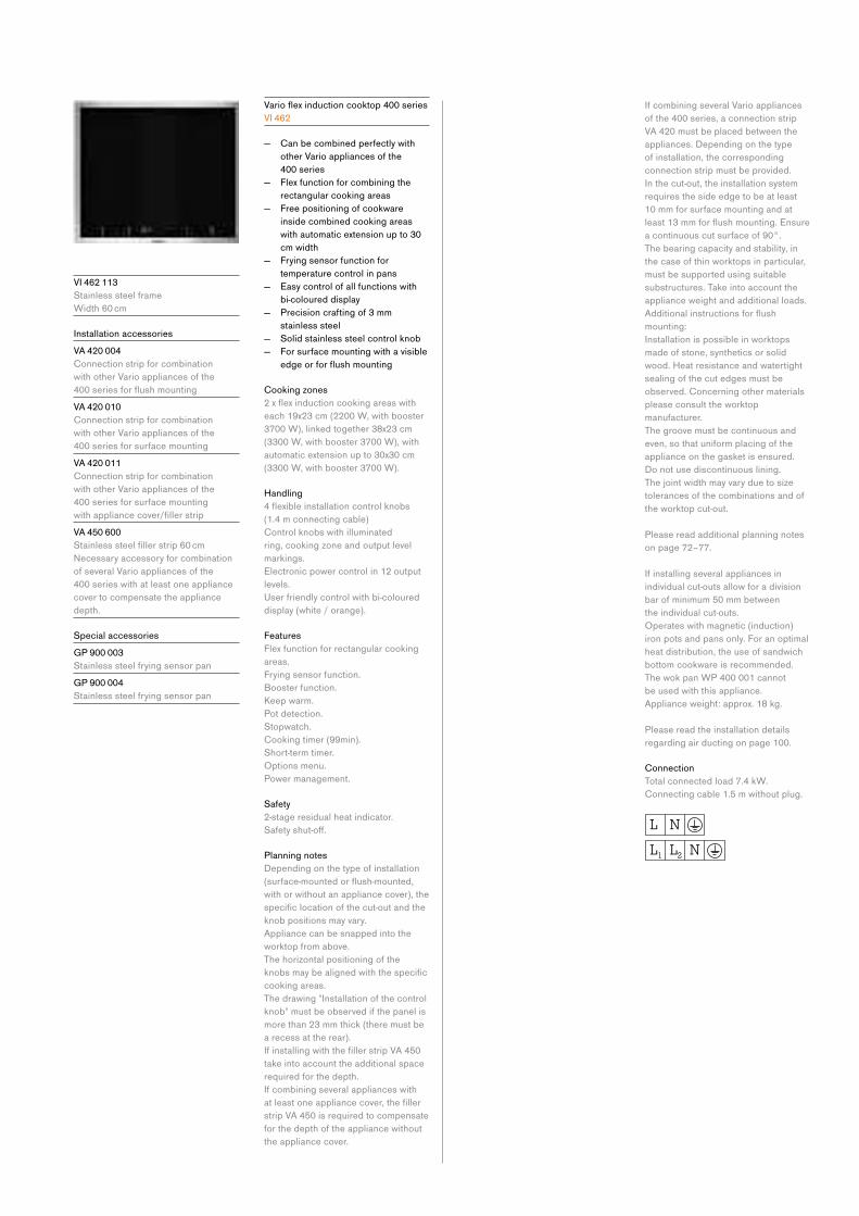
V I 462 113
Stainless steel frame
Width 60 cm
Installation accessories
V A 420 004
Connection strip for combination
with other Vario appliances of the
400seriesforflushmountingV A 420 010
Connection strip for combination
with other Vario appliances of the
400 series for surface mounting
V A 420 011
Connection strip for combination
with other Vario appliances of the
400 series for surface mounting
withappliancecover/fillerstripV A 450 600
Stainlesssteelfillerstrip60cmNecessaryaccessoryforcombinationof several Vario appliances of the
400 series with at least one appliance
cover to compensate the appliance
depth.
Special accessories
G P 900 003
Stainless steel frying sensor pan
G P 900 004
Stainless steel frying sensor pan
Varioflexinductioncooktop400seriesV I 462
— Can be combined perfectly with
other Vario appliances of the
400 series
— Flex function for combining the
rectangular cooking areas
— Free positioning of cookware
inside combined cooking areas
with automatic extension up to 30
cm width
— Frying sensor function for
temperature control in pans
— Easy control of all functions with
bi-coloured display
— Precision crafting of 3 mm
stainless steel
— Solid stainless steel control knob
— For surface mounting with a visible
edgeorforflushmounting
Cooking zones
2xflexinductioncookingareaswitheach 19x23 cm (2200 W, with booster
3700 W), linked together 38x23 cm
(3300 W, with booster 3700 W), with
automatic extension up to 30x30 cm
(3300 W, with booster 3700 W).
Handling
4flexibleinstallationcontrolknobs (1.4 m connecting cable)
Control knobs with illuminated
ring, cooking zone and output level
markings.
Electronic power control in 12 output
levels.
User friendly control with bi-coloured
display (white / orange).
Features
Flex function for rectangular cooking
areas.
Frying sensor function.
Booster function.
Keep warm.
Pot detection.
Stopwatch.
Cooking timer (99min).
Short-term timer.
Options menu.
Power management.
Safety
2-stage residual heat indicator.
Safetyshut-off.
Planning notes
Depending on the type of installation
(surface-mountedorflush-mounted,with or without an appliance cover), the
specificlocationofthecut-outandtheknob positions may vary.
Appliance can be snapped into the
worktop from above.
The horizontal positioning of the
knobsmaybealignedwiththespecificcooking areas.
The drawing "Installation of the control
knob" must be observed if the panel is
more than 23 mm thick (there must be
a recess at the rear).
IfinstallingwiththefillerstripVA450take into account the additional space
required for the depth.
If combining several appliances with
atleastoneappliancecover,thefillerstrip VA 450 is required to compensate
for the depth of the appliance without
the appliance cover.
If combining several Vario appliances
of the 400 series, a connection strip
VA 420 must be placed between the
appliances. Depending on the type
of installation, the corresponding
connection strip must be provided.
In the cut-out, the installation system
requires the side edge to be at least
10 mm for surface mounting and at
least13mmforflushmounting.Ensurea continuous cut surface of 90°.
The bearing capacity and stability, in
the case of thin worktops in particular,
must be supported using suitable
substructures. Take into account the
appliance weight and additional loads.
Additionalinstructionsforflushmounting:
Installation is possible in worktops
made of stone, synthetics or solid
wood. Heat resistance and watertight
sealing of the cut edges must be
observed. Concerning other materials
please consult the worktop
manufac turer.
The groove must be continuous and
even, so that uniform placing of the
appliance on the gasket is ensured.
Do not use discontinuous lining.
The joint width may vary due to size
tolerances of the combinations and of
the worktop cut-out.
Please read additional planning notes
on page 72–77.
If installing several appliances in
individual cut-outs allow for a division
bar of minimum 50 mm between
the individual cut-outs.
Operates with magnetic (induction)
iron pots and pans only. For an optimal
heat distribution, the use of sandwich
bottom cookware is recommended.
The wok pan WP 400 001 cannot
be used with this appliance.
Appliance weight: approx. 18 kg.
Please read the installation details
regarding air ducting on page 100.
Connection
Total connected load 7.4 kW.
Connecting cable 1.5 m without plug.

55Vario cooktops
measurements in mm
520
492±1
ø 50
ø 60
≥ 50
> 35
569±1
590
90
208 90
3
54
90°
R 3
1500
A: 3.5-0.5
measurements in mm
≥ 50
dia.50
dia. 60
492±1
520
524+1
≥ 50
> 35
(A)
90°
594+1
569±1
590
90
208 90
3
57
1500
R 3
R 4+1
Installation of the control knob; flush installation
23
≤ 23>23
> 35 > 35
70
35
ø 50ø 50
measurements in mm
≤ 23
Installation of the control knob; surface mounting
23
70
35
≤ 23> 23
> 35 > 35
ø 50 ø 50
measurements in mm
≤ 23
View from above
measurements in mm
594+1
524+1
492±1
569±1
R 3
+1R 4
Longitudinal section
A: 3.5-0.5 B: Fill with silicone
measurements in mm
569±1
590
2 2
594+1
(B)
(A)
Cross-section
A: 3.5-0.5
B: Fill with silicone
measurements in mm
492±1
524+1
2 2
520 (B)
(A)

V I 422 113
Stainless steel frame
Width 38 cm
Installation accessories
V A 420 004
Connection strip for combination
with other Vario appliances of the
400seriesforflushmountingV A 420 010
Connection strip for combination
with other Vario appliances of the
400 series for surface mounting
V A 420 011
Connection strip for combination
with other Vario appliances of the
400 series for surface mounting
withappliancecover/fillerstripV A 450 401
Stainlesssteelfillerstrip38cmNecessaryaccessoryforcombinationof several Vario appliances of the
400 series with at least one appliance
cover to compensate the appliance
depth.
Special accessories
G P 900 003
Stainless steel frying sensor pan
Varioflexinductioncooktop400seriesV I 422
— Can be combined perfectly with
other Vario appliances of the
400 series
— Flex function for combining the
rectangular cooking areas
— Free positioning of cookware
inside combined cooking areas
— Frying sensor function for
temperature control in pans
— Easy control of all functions with
bicoloured display
— Solid stainless steel control knob
— Precision crafting of 3 mm
stainless steel
— For surface mounting with a visible
edgeorforflushmounting
Cooking zones
2flexinductioncookingareas 19x24 cm (2200 W, with booster
3700 W), linked together 38x24 cm
(3300 W, with booster 3700 W).
Handling
2flexibleinstallationcontrolknobs (1m connecting cable)
Control knobs with illuminated
ring, cooking zone and output level
markings.
Electronic power control in 12 output
levels.
User friendly control with bicoloured
display (white / orange).
Features
Flex function for rectangular cooking
areas.
Frying sensor function.
Booster function.
Stopwatch.
Short-term timer.
Options menu.
Safety
Individual residual heat indicators.
Safetyshut-off.
Planning notes
Depending on the type of installation
(surface-mountedorflush-mounted,with or without an appliance cover), the
specificlocationofthecut-outandtheknob positions may vary.
Appliance can be snapped into the
worktop from above.
The drawing “Installation of the control
knob” must be observed if the panel is
more than 23 mm thick (there must be
a recess at the rear).
The horizontal positioning of the
knobsmaybealignedwiththespecificcooking areas.
Ifinstallingwiththefillerstrip VA 450 take into account the additional
space required for the depth.
If combining several appliances with
atleastoneappliancecover,thefillerstrip VA 450 is required to compensate
for the depth of the appliance without
the appliance cover.
If combining several Vario appliances
of the 400 series, a connection strip
VA 420 must be placed between the
appliances. Depending on the type
of installation, the corresponding
connection strip must be provided.
In the cut-out, the installation system
requires the side edge to be at least
10 mm for surface mounting and at
least13mmforflushmounting.Ensurea continuous cut surface of 90°.
The bearing capacity and stability, in
the case of thin worktops in particular,
must be supported using suitable
substructures. Take into account
the appliance weight and additional
loads.Additionalinstructionsforflushmounting:
Installation is possible in worktops
made of stone, synthetics or solid
wood. Heat resistance and watertight
sealing of the cut edges must be
observed. Concerning other materials
please consult the worktop manufac-
turer.
The groove must be continuous and
even, so that uniform placing of the
appliance on the gasket is ensured.
Do not use discontinuous lining.
The joint width may vary due to size
tolerances of the combinations and of
the worktop cut-out.
Please read additional planning notes
on page 72–77.
If installing several appliances in
individual cut-outs allow for a division
bar of minimum 50 mm between the
individual cut-outs.
Operates with magnetic (induction)
iron pots and pans only. For an optimal
heat distribution, the use of sandwich
bottom cookware is recommended.
Appliance weight: approx. 10 kg.
Please read the installation details
regarding air ducting on page 100.
Connection
Total connected load 3.7 kW.
Connecting cable 1.5 m without plug.
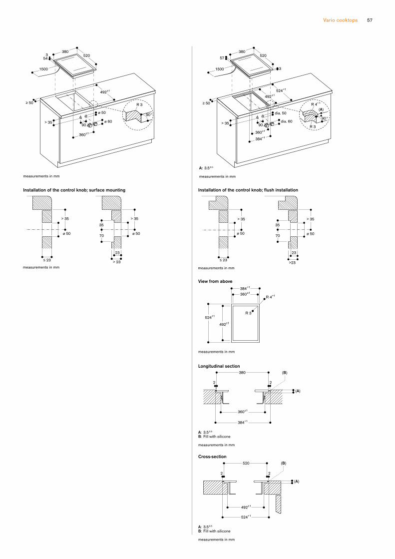
57Vario cooktops
measurements in mm
1500
520
492±1
> 35
ø 50
ø 60
≥ 50
380
360±1
90
354
90°
R 3
A: 3.5-0.5
measurements in mm
≥ 50
dia. 50
dia. 60
1500
492±1
520
524+1
≥ 50
> 35
380
384+1
360±1
90
57
3
(A)
90°
R 3
R 4+1
measurements in mm
≤ 23
Installation of the control knob; flush installation
23
≤ 23>23
> 35 > 35
70
35
ø 50ø 50
measurements in mm
≤ 23> 23
Installation of the control knob; surface mounting
23
70
35
≤ 23> 23
> 35 > 35
ø 50 ø 50
Longitudinal section
A: 3.5-0.5
B: Fill with silicone
measurements in mm
380 (B)
(A)
360±1
2 2
384+1
View from above
measurements in mm
384+1
360±1
524+1
492±1
R 3
R 4+1
Cross-section
A: 3.5-0.5
B: Fill with silicone
measurements in mm
492±1
524+1
2 2
520 (B)
(A)
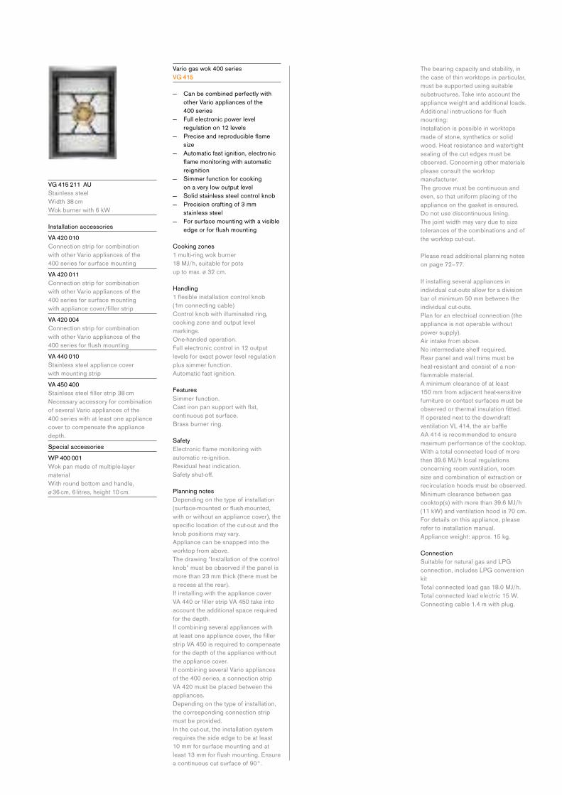
V G 415 211 AU
Stainless steel
Width 38 cm
Wok burner with 6 kW
Installation accessories
V A 420 010
Connection strip for combination
with other Vario appliances of the
400 series for surface mounting
V A 420 011
Connection strip for combination
with other Vario appliances of the
400 series for surface mounting
withappliancecover/fillerstripV A 420 004
Connection strip for combination
with other Vario appliances of the
400seriesforflushmountingV A 440 010
Stainless steel appliance cover
with mounting strip
V A 450 400
Stainlesssteelfillerstrip38cmNecessaryaccessoryforcombinationof several Vario appliances of the
400 series with at least one appliance
cover to compensate the appliance
depth.
Special accessories
W P 400 001
Wok pan made of multiple-layer
material
With round bottom and handle,
ø 36 cm, 6 litres, height 10 cm.
Vario gas wok 400 series
V G 415
— Can be combined perfectly with
other Vario appliances of the
400 series
— Full electronic power level
regulation on 12 levels
— Preciseandreproducibleflamesize
— Automatic fast ignition, electronic
flamemonitoringwithautomaticreignition
— Simmer function for cooking
on a very low output level
— Solid stainless steel control knob
— Precision crafting of 3 mm
stainless steel
— For surface mounting with a visible
edgeorforflushmounting
Cooking zones
1 multi-ring wok burner
18 MJ/h, suitable for pots
up to max. ø 32 cm.
Handling
1flexibleinstallationcontrolknob (1m connecting cable)
Control knob with illuminated ring,
cooking zone and output level
markings.
One-handed operation.
Full electronic control in 12 output
levels for exact power level regulation
plus simmer function.
Automatic fast ignition.
Features
Simmer function.
Castironpansupportwithflat,continuous pot surface.
Brass burner ring.
Safety
Electronicflamemonitoringwithautomatic re-ignition.
Residual heat indication.
Safetyshut-off.
Planning notes
Depending on the type of installation
(surface-mountedorflush-mounted,with or without an appliance cover), the
specificlocationofthecut-outandtheknob positions may vary.
Appliance can be snapped into the
worktop from above.
The drawing "Installation of the control
knob" must be observed if the panel is
more than 23 mm thick (there must be
a recess at the rear).
If installing with the appliance cover
VA440orfillerstripVA450takeintoaccount the additional space required
for the depth.
If combining several appliances with
atleastoneappliancecover,thefillerstrip VA 450 is required to compensate
for the depth of the appliance without
the appliance cover.
If combining several Vario appliances
of the 400 series, a connection strip
VA 420 must be placed between the
appliances.
Depending on the type of installation,
the corresponding connection strip
must be provided.
In the cut-out, the installation system
requires the side edge to be at least
10 mm for surface mounting and at
least13mmforflushmounting.Ensurea continuous cut surface of 90°.
The bearing capacity and stability, in
the case of thin worktops in particular,
must be supported using suitable
substructures. Take into account the
appliance weight and additional loads.
Additionalinstructionsforflushmounting:
Installation is possible in worktops
made of stone, synthetics or solid
wood. Heat resistance and watertight
sealing of the cut edges must be
observed. Concerning other materials
please consult the worktop
manufacturer.
The groove must be continuous and
even, so that uniform placing of the
appliance on the gasket is ensured.
Do not use discontinuous lining.
The joint width may vary due to size
tolerances of the combinations and of
the worktop cut-out.
Please read additional planning notes
on page 72–77.
If installing several appliances in
individual cut-outs allow for a division
bar of minimum 50 mm between the
individual cut-outs.
Plan for an electrical connection (the
appliance is not operable without
power supply).
Air intake from above.
Nointermediateshelfrequired.Rear panel and wall trims must be
heat-resistant and consist of a non-
flammablematerial.A minimum clearance of at least
150 mm from adjacent heat-sensitive
furniture or contact surfaces must be
observedorthermalinsulationfitted.If operated next to the downdraft
ventilationVL414,theairbaffle AA 414 is recommended to ensure
maximum performance of the cooktop.
With a total connected load of more
than 39.6 MJ/h local regulations
concerning room ventilation, room
size and combination of extraction or
recirculation hoods must be observed.
Minimum clearance between gas
cooktop(s) with more than 39.6 MJ/h
(11 kW) and ventilation hood is 70 cm.
For details on this appliance, please
refer to installation manual.
Appliance weight: approx. 15 kg.
Connection
Suitable for natural gas and LPG
connection, includes LPG conversion
kit
Total connected load gas 18.0 MJ/h.
Total connected load electric 15 W.
Connecting cable 1.4 m with plug.

59Vario cooktops
A: When installing with appliance cover, take the deeper cut-out into consideration (observe separate planning notes)
measurements in mm
520 (A)
492±1 (A)
≥ 50
> 35
90°
1400
360±1
3
380
131
15
R 3
ø 60
ø 50
A:
dia. 50
dia. 60R 3
R 5+1
When installing with appliance cover, take the deeper cut-out into consideration (observe separate planning notes)
B: 3.5-0.5
measurements in mm
492±1 (A)
526+1 (A)
109-166
≥ 50 ≥ 35
520 (A)
1400
386±1
360±1
3
380
134
15
90°
(B)
measurements in mm
≤ 23
Installation of the control knob; flush installation
23
≤ 23>23
> 35 > 35
70
35
ø 50ø 50
Installation of the control knob; surface mounting
23
70
35
≤ 23> 23
> 35 > 35
ø 50 ø 50
measurements in mm
≤ 23
A: 3.5–0.5
6.5+0.5 in combinations with frameless induction cooktops B: Fill with silicone
measurements in mm
Longitudinal section
A: 3.5–0.5
(A)
(B)
360±1
380
384+1
22
A: When installing with appliance cover, take the deeper cut-out into consideration (observe separate planning notes)
measurements in mm
View from above
384+1
360±1
524+1 (A)
492±1 (A)
R 3
R 4+1
Cross-section
A:
17 17
3 3
(B)
(A)
492±1
526±1
520
A: 3.5-0.5
B: Fill with silicone
When installing with appliance cover, pay attention to the deeper cut-out and the front and rear groove width.
measurements in mm

V G 425 211 AU
Stainless steel
Width 38 cm
4 kW in 2 burners
Installation accessories
V A 420 010
Connection strip for combination
with other Vario appliances of the
400 series for surface mounting
V A 420 011
Connection strip for combination
with other Vario appliances of the
400 series for surface mounting
withappliancecover/fillerstripV A 420 004
Connection strip for combination
with other Vario appliances of the
400seriesforflushmountingV A 440 010
Stainless steel appliance cover
with mounting strip
V A 450 400
Stainlesssteelfillerstrip38cmNecessaryaccessoryforcombinationof several Vario appliances of the
400 series with at least one appliance
cover to compensate the appliance
depth.
Vario gas cooktop 400 series
V G 425
— Can be combined perfectly with
other Vario appliances of the
400 series
— Full electronic power level
regulation on 12 levels
— Preciseandreproducibleflamesize
— Automatic fast ignition, electronic
flamemonitoringwithautomaticreignition
— Simmer function for cooking
on a very low output level
— Solid stainless steel control knob
— Precision crafting of 3 mm
stainless steel
— For surface mounting with a visible
edgeorforflushmounting
Cooking zones
1 two-ring high output burner
14.0 MJ/h, suitable for pots up to
max. ø 28 cm.
1 two-ring standard output burner
6.5 MJ/h, suitable for pots up to
max. ø 24 cm.
Handling
2flexibleinstallationcontrolknobs (1m connecting cable)
Control knobs with illuminated
ring, cooking zone and output level
markings.
One-handed operation.
Full electronic control in 12 output
levels for exact power level regulation
plus simmer function.
Automatic fast ignition.
Features
Simmer function.
Castironpansupportwithflat,continuous pot surface.
Brass burner rings.
Safety
Electronicflamemonitoringwithautomatic re-ignition.
Residual heat indication.
Safetyshut-off.
Planning notes
Depending on the type of installation
(surface-mountedorflush-mounted,with or without an appliance cover), the
specificlocationofthecut-outandtheknob positions may vary.
Appliance can be snapped into the
worktop from above.
The drawing "Installation of the control
knob" must be observed if the panel is
more than 23 mm thick (there must be
a recess at the rear).
If installing with the appliance cover
VA440orfillerstripVA450takeintoaccount the additional space required
for the depth.
If combining several appliances with
atleastoneappliancecover,thefillerstrip VA 450 is required to compensate
for the depth of the appliance without
the appliance cover.
If combining several Vario appliances
of the 400 series, a connection strip
VA 420 must be placed between the
appliances.
Depending on the type of installation,
the corresponding connection strip
must be provided.
In the cut-out, the installation system
requires the side edge to be at least
10 mm for surface mounting and at
least13mmforflushmounting.Ensurea continuous cut surface of 90°.
The bearing capacity and stability, in
the case of thin worktops in particular,
must be supported using suitable
substructures. Take into account the
appliance weight and additional loads.
Additionalinstructionsforflushmounting:
Installation is possible in worktops
made of stone, synthetics or solid
wood. Heat resistance and watertight
sealing of the cut edges must be
observed. Concerning other materials
please consult the worktop
manufacturer.
The groove must be continuous and
even, so that uniform placing of the
appliance on the gasket is ensured.
Do not use discontinuous lining.
The joint width may vary due to size
tolerances of the combinations and of
the worktop cut-out.
Please read additional planning notes
on page 72–77.
If installing several appliances in
individual cut-outs allow for a division
bar of minimum 50 mm between the
individual cut-outs.
Plan for an electrical connection (the
appliance is not operable without
power supply).
Air intake from above.
Nointermediateshelfrequired.Rear panel and wall trims must be
heat-resistant and consist of a non-
flammablematerial.A minimum clearance of at least
150 mm from adjacent heat-sensitive
furniture or contact surfaces must be
observedorthermalinsulationfitted.If operated next to the downdraft
ventilationVL414,theairbaffle AA 414 is recommended to ensure
maximum performance of the cooktop.
With a total connected load of more
than 39.6 MJ/h local regulations
concerning room ventilation, room
size and combination of extraction or
recirculation hoods must be observed.
Minimum clearance between gas
cooktop(s) with more than 39.6 MJ/h
(11 kW) and ventilation hood is 70 cm.
For details on this appliance, please
refer to installation manual.
Appliance weight: approx. 13 kg.
Connection
Suitable for natural gas and LPG
connection, includes LPG
conversion kit.
Total connected load gas 20.5 MJ/h.
Total connected load electric 15.0 W.
Connecting cable 1.4 m with plug.
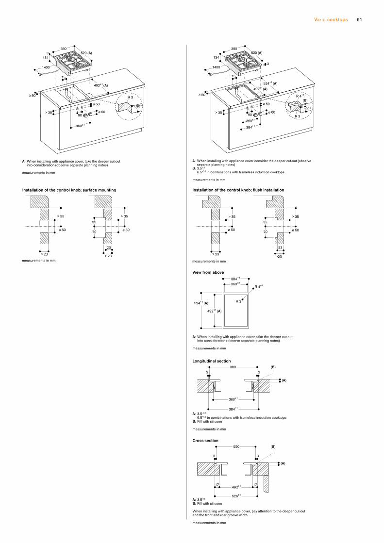
61Vario cooktops
measurements in mm
A: When installing with appliance cover, take the deeper cut-out into consideration (observe separate planning notes)
520 (A)
492±1 (A)
≥ 50
> 35
90°
1400
360±1
3
380
131
15
90ø 60
ø 50
R 3
A: When installing with appliance cover consider the deeper cut-out (observe separate planning notes) B: 3.5-0.5
6.5+0.5 in combinations with frameless induction cooktops
measurements in mm
492 ±1 ( A ) 524 +1 ( A )
ø 50
ø 60
≥ 50
> 35
520 ( A )
1400
384+1
360±1
3
380
134
15
90 R 3
R 4 +1
90°
( B )
measurements in mm
≤ 23
Installation of the control knob; flush installation
23
≤ 23>23
> 35 > 35
70
35
ø 50ø 50
measurements in mm
≤ 23
Installation of the control knob; surface mounting
23
70
35
≤ 23> 23
> 35 > 35
ø 50 ø 50
A: 3.5–0.5
6.5+0.5 in combinations with frameless induction cooktops B: Fill with silicone
measurements in mm
Longitudinal section
A: 3.5–0.5
(A)
(B)
360±1
380
384+1
22
View from above
A: When installing with appliance cover, take the deeper cut-out into consideration (observe separate planning notes)
measurements in mm
384+1
360±1
524+1 (A)
492±1 (A)
R 3
R 4+1
Cross-section
17 17
3 3
(B)
(A)
492±1
526±1
520
A: 3.5-0.5
B: Fill with silicone
When installing with appliance cover, pay attention to the deeper cut-out and the front and rear groove width.
measurements in mm
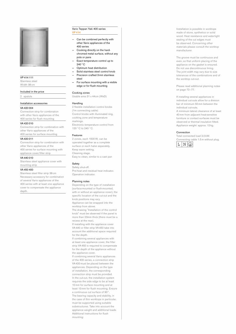
V P 414 111
Stainless steel
Width 38 cm
Included in the price
2 spatula
Installation accessories
V A 420 004
Connection strip for combination
with other Vario appliances of the
400seriesforflushmountingV A 420 010
Connection strip for combination with
other Vario appliances of the
400 series for surface mounting
V A 420 011
Connection strip for combination with
other Vario appliances of the
400 series for surface mounting with
appliancecover/fillerstripV A 440 010
Stainless steel appliance cover with
mounting strip
V A 450 400
Stainlesssteelfillerstrip38cmNecessaryaccessoryforcombinationof several Vario appliances of the
400 series with at least one appliance
cover to compensate the appliance
depth.
Vario Teppan Yaki 400 series
V P 414
— Can be combined perfectly with
other Vario appliances of the
400 series
— Cooking directly on the hard-
chromed metal surface, without any
pots or pans
— Exact temperature control up to
240 °C
— Optimum heat distribution
— Solid stainless steel control knob
— Precision crafted 3 mm stainless
steel
— For surface mounting with a visible
edgeorforflushmounting
Cooking zones
Usable area 31 x 44cm (WxD)
Handling
2flexibleinstallationcontrolknobs(1m connecting cable)
Control knobs with illuminated ring,
cooking zone and temperature
markings.
Electronic temperature control from
120 °C to 240 °C.
Features
2 zones, each 1500 W, can be
operated together as a complete
surface or each halve separately.
Keep warm setting.
Cleaning stage.
Easy to clean, similar to a cast pan
Safety
Safetyshut-off.Pre-heat and residual heat indicator.
Operation indicator.
Planning notes
Depending on the type of installation
(surface-mountedorflush-mounted,with or without an appliance cover), the
specificlocationofthecut-outandtheknob positions may vary.
Appliance can be snapped into the
worktop from above.
Thedrawing‟Installationofthecontrolknob” must be observed if the panel is
more than 23mm thick (there must be a
recess at the rear).
If installing with the appliance cover
VA440orfillerstripVA450takeintoaccount the additional space required
for the depth.
If combining several appliances with
atleastoneappliancecover,thefillerstrip VA 450 is required to compensate
for the depth of the appliance without
the appliance cover.
If combining several Vario appliances
of the 400 series, a connection strip
VA 420 must be placed between the
appliances. Depending on the type
of installation, the corresponding
connection strip must be provided.
In the cut-out, the installation system
requires the side edge to be at least
10 mm for surface mounting and at
least13mmforflushmounting.Ensurea continuous cut surface of 90°.
The bearing capacity and stability, in
the case of thin worktops in particular,
must be supported using suitable
substructures. Take into account the
appliance weight and additional loads.
Additionalinstructionsforflushmounting:
Installation is possible in worktops
made of stone, synthetics or solid
wood. Heat resistance and watertight
sealing of the cut edges must
be observed. Concerning other
materials please consult the worktop
manufacturer.
The groove must be continuous and
even, so that uniform placing of the
appliance on the gasket is ensured.
Do not use discontinuous lining.
The joint width may vary due to size
tolerances of the combinations and of
the worktop cut-out.
Please read additional planning notes
on page 72–77.
If installing several appliances in
individual cut-outs allow for a division
bar of minimum 50 mm between the
individual cut-outs.
A minimum lateral clearance of at least
40 mm from adjacent heat-sensitive
furniture or contact surfaces must be
observedorthermalinsulationfitted.Appliance weight: approx. 12 kg.
Connection
Total connected load 3.0 kW.
Connecting cable 1.5 m without plug.

63Vario cooktops
A:
dia. 50
dia. 60
R 3
When installing with appliance cover, take the deeper cut-out into consideration (observe separate planning notes)
B: 130 mm in the area of the cable clamp (left, on the rear side)
measurements in mm
3
360±1
90
520 (A)
380
115 (B)
492±1 (A)
≥ 50
> 35
90°
1500
A: When installing with appliance cover consider the deeper cut-out (observe separate planning notes) B: 133 mm in the area of the cable clamp (left, on the rear side) C: 3.5–0.5
6.5+0.5 in combinations with frameless induction cooktops
measurements in mm
520 ( A ) 380
3
384 +1 360 ±1
492 ±1 ( A ) 524 +1 ( A )
( C )
90
118 ( B )
ø 50
ø 60
R 3
R 4 +1
90°
≥ 50
> 35
1500
measurements in mm
≤ 23>23
Installation of the control knob; flush installation
23
≤ 23>23
> 35 > 35
70
35
ø 50ø 50
measurements in mm
≤ 23> 23
Installation of the control knob; surface mounting
23
70
35
≤ 23> 23
> 35 > 35
ø 50 ø 50
Longitudinal section
A: 3.5–0.5
6.5+0.5 in combinations with frameless induction cooktops B: Fill with silicone
measurements in mm
(A)
(B)
360±1
380
384+1
22
View from above
384+1
360±1
524+1 (A)
492±1 (A)
R 3
R 4+1
measurements in mm
Cross-section
A: 3.5-0.5
B: Fill with silicone
measurements in mm
492±1
524+1
2 2
520 (B)
(A)
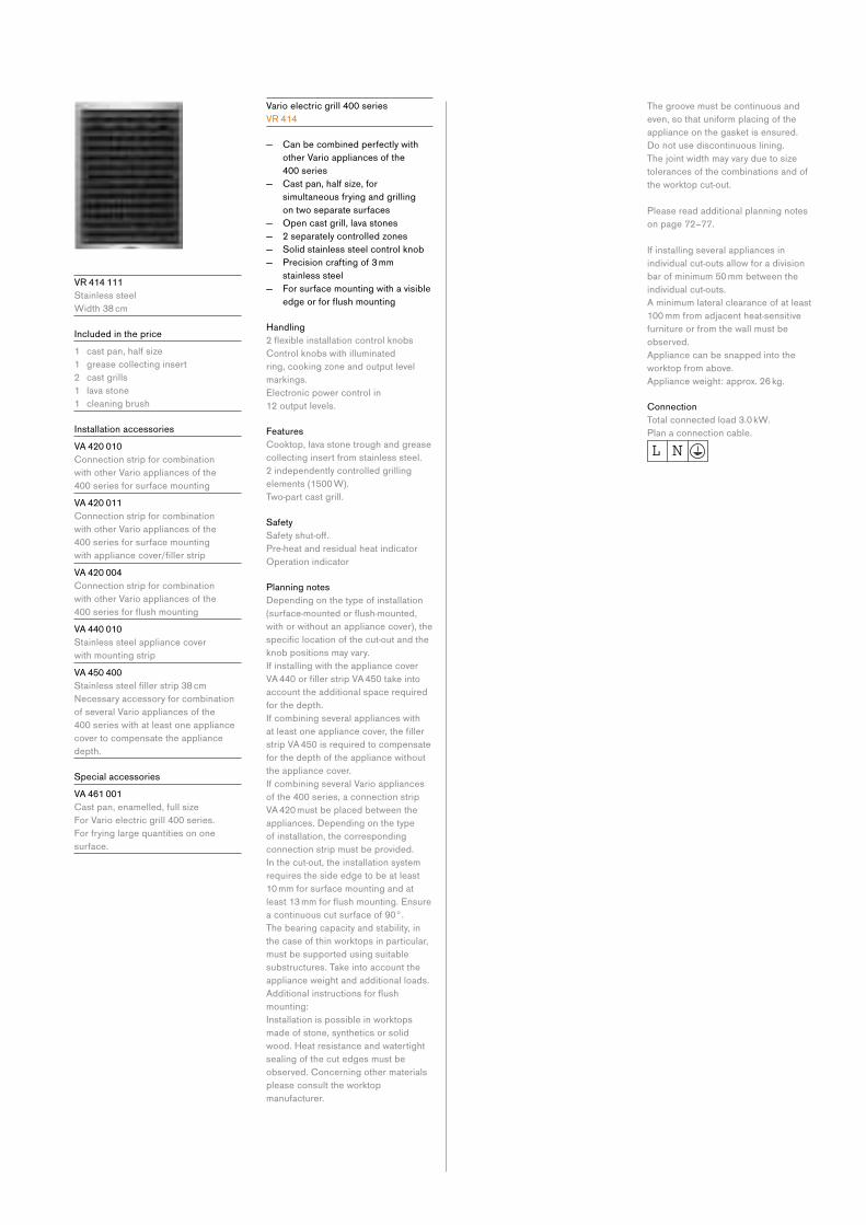
V R 414 111
Stainless steel
Width 38 cm
Included in the price
1 cast pan, half size
1 grease collecting insert
2 cast grills
1 lava stone
1 cleaning brush
Installation accessories
V A 420 010
Connection strip for combination
with other Vario appliances of the
400 series for surface mounting
V A 420 011
Connection strip for combination
with other Vario appliances of the
400 series for surface mounting
withappliancecover/fillerstripV A 420 004
Connection strip for combination
with other Vario appliances of the
400seriesforflushmountingV A 440 010
Stainless steel appliance cover
with mounting strip
V A 450 400
Stainlesssteelfillerstrip38cmNecessaryaccessoryforcombinationof several Vario appliances of the
400 series with at least one appliance
cover to compensate the appliance
depth.
Special accessories
V A 461 001
Cast pan, enamelled, full size
For Vario electric grill 400 series.
For frying large quantities on one
surface.
Vario electric grill 400 series
V R 414
— Can be combined perfectly with
other Vario appliances of the
400 series
— Cast pan, half size, for
simultaneous frying and grilling
on two separate surfaces
— Open cast grill, lava stones
— 2 separately controlled zones
— Solid stainless steel control knob
— Precision crafting of 3 mm
stainless steel
— For surface mounting with a visible
edgeorforflushmounting
Handling
2flexibleinstallationcontrolknobsControl knobs with illuminated
ring, cooking zone and output level
markings.
Electronic power control in
12 output levels.
Features
Cooktop, lava stone trough and grease
collecting insert from stainless steel.
2 independently controlled grilling
elements (1500 W).
Two-part cast grill.
Safety
Safetyshut-off.Pre-heat and residual heat indicator
Operation indicator
Planning notes
Depending on the type of installation
(surface-mountedorflush-mounted,with or without an appliance cover), the
specificlocationofthecut-outandtheknob positions may vary.
If installing with the appliance cover
VA440orfillerstripVA450takeintoaccount the additional space required
for the depth.
If combining several appliances with
atleastoneappliancecover,thefillerstrip VA 450 is required to compensate
for the depth of the appliance without
the appliance cover.
If combining several Vario appliances
of the 400 series, a connection strip
VA 420 must be placed between the
appliances. Depending on the type
of installation, the corresponding
connection strip must be provided.
In the cut-out, the installation system
requires the side edge to be at least
10 mm for surface mounting and at
least13mmforflushmounting.Ensurea continuous cut surface of 90°.
The bearing capacity and stability, in
the case of thin worktops in particular,
must be supported using suitable
substructures. Take into account the
appliance weight and additional loads.
Additionalinstructionsforflushmounting:
Installation is possible in worktops
made of stone, synthetics or solid
wood. Heat resistance and watertight
sealing of the cut edges must be
observed. Concerning other materials
please consult the worktop
manufacturer.
The groove must be continuous and
even, so that uniform placing of the
appliance on the gasket is ensured.
Do not use discontinuous lining.
The joint width may vary due to size
tolerances of the combinations and of
the worktop cut-out.
Please read additional planning notes
on page 72–77.
If installing several appliances in
individual cut-outs allow for a division
bar of minimum 50 mm between the
individual cut-outs.
A minimum lateral clearance of at least
100 mm from adjacent heat-sensitive
furniture or from the wall must be
observed.
Appliance can be snapped into the
worktop from above.
Appliance weight: approx. 26 kg.
Connection
Total connected load 3.0 kW.
Plan a connection cable.
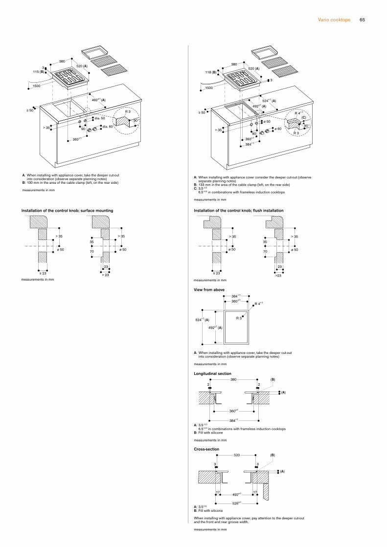
65Vario cooktops
A:
dia. 50
dia. 60
R 3
When installing with appliance cover, take the deeper cut-out into consideration (observe separate planning notes)
B: 130 mm in the area of the cable clamp (left, on the rear side)
measurements in mm
520 (A)
115 (B)
492±1 (A)
≥ 50
> 35
90°
3
360±1
90
380
1500
A: When installing with appliance cover consider the deeper cut-out (observe separate planning notes) B: 133 mm in the area of the cable clamp (left, on the rear side) C: 3.5–0.5
6.5+0.5 in combinations with frameless induction cooktops
measurements in mm
520 ( A )
492 ±1 ( A ) 524 +1 ( A )
118 ( B )
ø 50
ø 60
R 3
R 4 +1
90°
≥ 50
> 35
1500
384+1
360±1
90
380
3
( C )
measurements in mm
≤ 23>23
Installation of the control knob; flush installation
23
≤ 23>23
> 35 > 35
70
35
ø 50ø 50
measurements in mm
≤ 23> 23
Installation of the control knob; surface mounting
23
70
35
≤ 23> 23
> 35 > 35
ø 50 ø 50
A: 3.5–0.5
6.5+0.5 in combinations with frameless induction cooktops B: Fill with silicone
measurements in mm
Longitudinal section
A: 3.5–0.5
(A)
(B)
360±1
380
384+1
22
View from above
A: When installing with appliance cover, take the deeper cut-out into consideration (observe separate planning notes)
measurements in mm
384+1
360±1
524+1 (A)
492±1 (A)
R 3
R 4+1
Cross-section
17 17
3 3
(B)
(A)
492±1
526±1
520
A: 3.5-0.5
B: Fill with silicone
When installing with appliance cover, pay attention to the deeper cut-out and the front and rear groove width.
measurements in mm
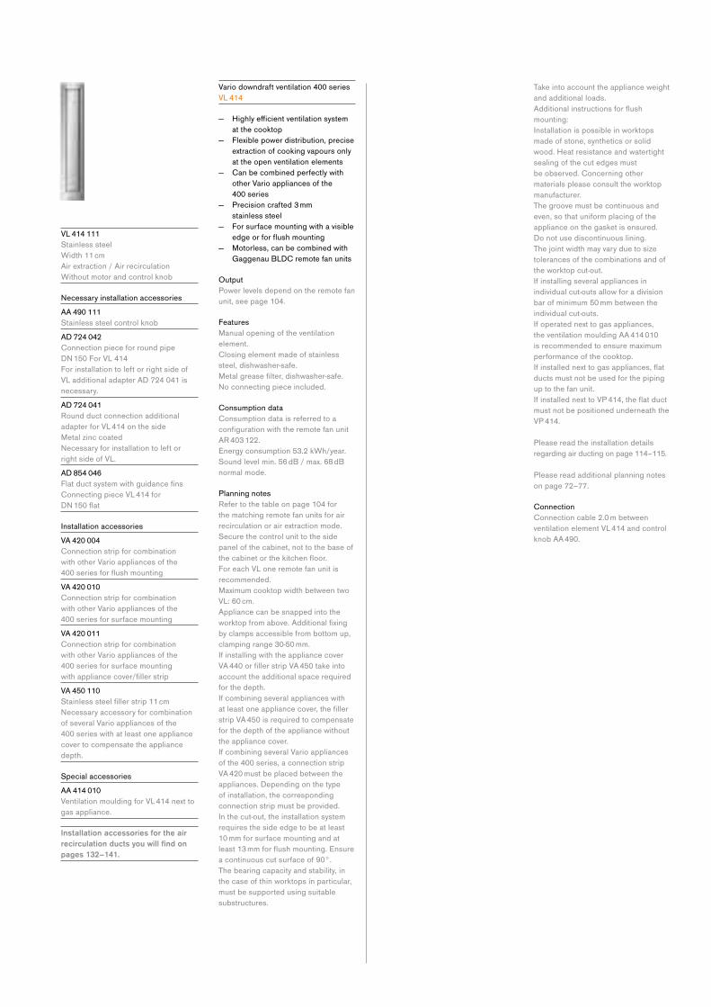
V L 414 111
Stainless steel
Width 11 cm
Air extraction / Air recirculation
Without motor and control knob
NecessaryinstallationaccessoriesA A 490 111
Stainless steel control knob
A D 724 042
Connection piece for round pipe
DN150ForVL414For installation to left or right side of
VL additional adapter AD 724 041 is
necessary.
A D 724 041
Round duct connection additional
adapter for VL 414 on the side
Metal zinc coated
Necessaryforinstallationtoleftorright side of VL.
A D 854 046
FlatductsystemwithguidancefinsConnecting piece VL 414 for
DN150flat
Installation accessories
V A 420 004
Connection strip for combination
with other Vario appliances of the
400seriesforflushmountingV A 420 010
Connection strip for combination
with other Vario appliances of the
400 series for surface mounting
V A 420 011
Connection strip for combination
with other Vario appliances of the
400 series for surface mounting
withappliancecover/fillerstripV A 450 110
Stainlesssteelfillerstrip11cmNecessaryaccessoryforcombinationof several Vario appliances of the
400 series with at least one appliance
cover to compensate the appliance
depth.
Special accessories
A A 414 010
Ventilation moulding for VL 414 next to
gas appliance.
Installation accessories for the air recirculation ducts you will find on pages 132–141.
Vario downdraft ventilation 400 series
V L 414
— Highlyefficientventilationsystem at the cooktop
— Flexible power distribution, precise
extraction of cooking vapours only
at the open ventilation elements
— Can be combined perfectly with
other Vario appliances of the
400 series
— Precision crafted 3 mm
stainless steel
— For surface mounting with a visible
edgeorforflushmounting — Motorless, can be combined with
Gaggenau BLDC remote fan units
Output
Power levels depend on the remote fan
unit, see page 104.
Features
Manual opening of the ventilation
element.
Closing element made of stainless
steel, dishwasher-safe.
Metalgreasefilter,dishwasher-safe.Noconnectingpieceincluded.
Consumption data
Consumption data is referred to a
configurationwiththeremotefanunitAR 403 122.
Energy consumption 53.2 kWh/year.
Sound level min. 56 dB / max. 68 dB
normal mode.
Planning notes
Refer to the table on page 104 for
the matching remote fan units for air
recirculation or air extraction mode.
Secure the control unit to the side
panel of the cabinet, not to the base of
thecabinetorthekitchenfloor.For each VL one remote fan unit is
recommended.
Maximum cooktop width between two
VL: 60 cm.
Appliance can be snapped into the
worktopfromabove.Additionalfixingby clamps accessible from bottom up,
clamping range 30-50 mm.
If installing with the appliance cover
VA440orfillerstripVA450takeintoaccount the additional space required
for the depth.
If combining several appliances with
atleastoneappliancecover,thefillerstrip VA 450 is required to compensate
for the depth of the appliance without
the appliance cover.
If combining several Vario appliances
of the 400 series, a connection strip
VA 420 must be placed between the
appliances. Depending on the type
of installation, the corresponding
connection strip must be provided.
In the cut-out, the installation system
requires the side edge to be at least
10 mm for surface mounting and at
least13mmforflushmounting.Ensurea continuous cut surface of 90°.
The bearing capacity and stability, in
the case of thin worktops in particular,
must be supported using suitable
substructures.
Take into account the appliance weight
and additional loads.
Additionalinstructionsforflushmounting:
Installation is possible in worktops
made of stone, synthetics or solid
wood. Heat resistance and watertight
sealing of the cut edges must
be observed. Concerning other
materials please consult the worktop
manufacturer.
The groove must be continuous and
even, so that uniform placing of the
appliance on the gasket is ensured.
Do not use discontinuous lining.
The joint width may vary due to size
tolerances of the combinations and of
the worktop cut-out.
If installing several appliances in
individual cut-outs allow for a division
bar of minimum 50 mm between the
individual cut-outs.
If operated next to gas appliances,
the ventilation moulding AA 414 010
is recommended to ensure maximum
performance of the cooktop.
Ifinstallednexttogasappliances,flatducts must not be used for the piping
up to the fan unit.
IfinstallednexttoVP414,theflatductmust not be positioned underneath the
VP 414.
Please read the installation details
regarding air ducting on page 114–115.
Please read additional planning notes
on page 72–77.
Connection
Connection cable 2.0 m between
ventilation element VL 414 and control
knob AA 490.

Vario cooktops 67
AD 854 046

A A 490 111
Stainless steel
Vario control knob ventilation 400 series
A A 490
— Solid stainless steel control knob
— Can be combined perfectly with
other Vario appliances of the
400 series
— Motorless, can be combined with
Gaggenau BLDC remote fan units
Handling
Control knob with illuminated ring and
output marking.
Features
3 electronically controlled power levels
and 1 intensive mode.
Run-on function, 6 min.
Planning notes
The separate electronics housing is to
be installed so that it is accessible.
Secure the control unit to the side
panel of the cabinet, not to the base of
thecabinetorthekitchenfloor.When installing a ventilation hood with
air extraction mode and a chimney-
ventedfireplace,thepowersupplylineof the ventilation appliance needs a
suitable safety switch.
Connection
Total connected load 10 W.
Connecting cable 1.8 m, with plug.

Vario cooktops 69
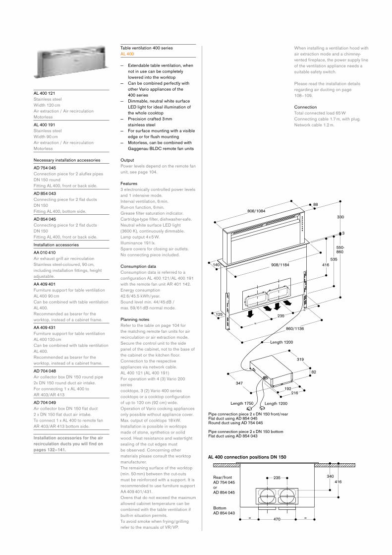
A L 400 121
Stainless steel
Width 120 cm
Air extraction / Air recirculation
Motorless
A L 400 191
Stainless steel
Width 90 cm
Air extraction / Air recirculation
Motorless
NecessaryinstallationaccessoriesA D 754 045
Connectionpiecefor2aluflexpipesDN150roundFitting AL 400, front or back side.
A D 854 043
Connectingpiecefor2flatductsDN150Fitting AL 400, bottom side.
A D 854 045
Connectingpiecefor2flatductsDN150Fitting AL 400, front or back side.
Installation accessories
A A 010 410
Air exhaust grill air recirculation
Stainless steel-coloured, 90 cm,
includinginstallationfittings,heightadjustable.
A A 409 401
Furniture support for table ventilation
AL 400 90 cm
Can be combined with table ventilation
AL 400.
Recommended as bearer for the
worktop, instead of a cabinet frame.
A A 409 431
Furniture support for table ventilation
AL 400 120 cm
Can be combined with table ventilation
AL 400.
Recommended as bearer for the
worktop, instead of a cabinet frame.
A D 704 048
AircollectorboxDN150roundpipe2xDN150roundductairintake.For connecting 1 x AL 400 to
AR 403/AR 413
A D 704 049
AircollectorboxDN150flatduct2xDN150flatductairintake.To connect 1 x AL 400 to remote fan
AR 403/AR 413 bottom side.
Installation accessories for the air recirculation ducts you will find on pages 132–141.
Table ventilation 400 series
A L 400
— Extendable table ventilation, when
not in use can be completely
lowered into the worktop
— Can be combined perfectly with
other Vario appliances of the
400 series
— Dimmable, neutral white surface
LED light for ideal illumination of
the whole cooktop
— Precision crafted 3 mm
stainless steel
— For surface mounting with a visible
edgeorforflushmounting — Motorless, can be combined with
Gaggenau BLDC remote fan units
Output
Power levels depend on the remote fan
unit, see page 104.
Features
3 electronically controlled power levels
and 1 intensive mode.
Interval ventilation, 6 min.
Run-on function, 6 min.
Greasefiltersaturationindicator.Cartridge-typefilter,dishwasher-safe.NeutralwhitesurfaceLEDlight (3600 K), continuously dimmable.
Lamp output 4 x 5 W.
Illuminance 191 lx.
Spare covers for closing air outlets.
Noconnectingpieceincluded.
Consumption data
Consumption data is referred to a
configurationAL400121/AL400191with the remote fan unit AR 401 142.
Energy consumption
42.6/45.5 kWh/year.
Sound level min. 44/45 dB /
max. 59/61 dB normal mode.
Planning notes
Refer to the table on page 104 for
the matching remote fan units for air
recirculation or air extraction mode.
Secure the control unit to the side
panel of the cabinet, not to the base of
thecabinetorthekitchenfloor.Connection to the respective
appliances via network cable.
AL 400 121 (AL 400 191)
For operation with 4 (3) Vario 200
series
cooktops, 3 (2) Vario 400 series
cooktopsoracooktopconfigurationof up to 120 cm (92 cm) wide.
Operation of Vario cooking appliances
only possible without appliance cover.
Max. output of cooktops 18 kW.
Installation is possible in worktops
made of stone, synthetics or solid
wood. Heat resistance and watertight
sealing of the cut edges must
be observed. Concerning other
materials please consult the worktop
manufacturer.
The remaining surface of the worktop
(min. 50 mm) between the cut-outs
must be reinforced with a support. It is
recommended to use furniture support
AA 409 401/431.
Ovens that do not exceed the maximum
allowed cabinet temperature can be
combined with the table ventilation if
built-in situation permits.
To avoid smoke when frying/grilling
refer to the manuals of VR/VP.
When installing a ventilation hood with
air extraction mode and a chimney-
ventedfireplace,thepowersupplylineof the ventilation appliance needs a
suitable safety switch.
Please read the installation details
regarding air ducting on page
108–109.
Connection
Total connected load 65 W
Connecting cable 1.7 m, with plug.
Networkcable1.2m.
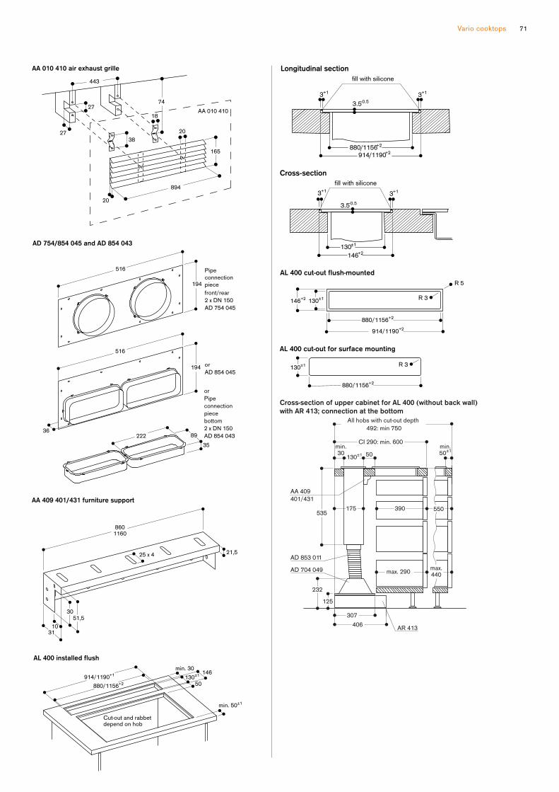
Vario cooktops 71
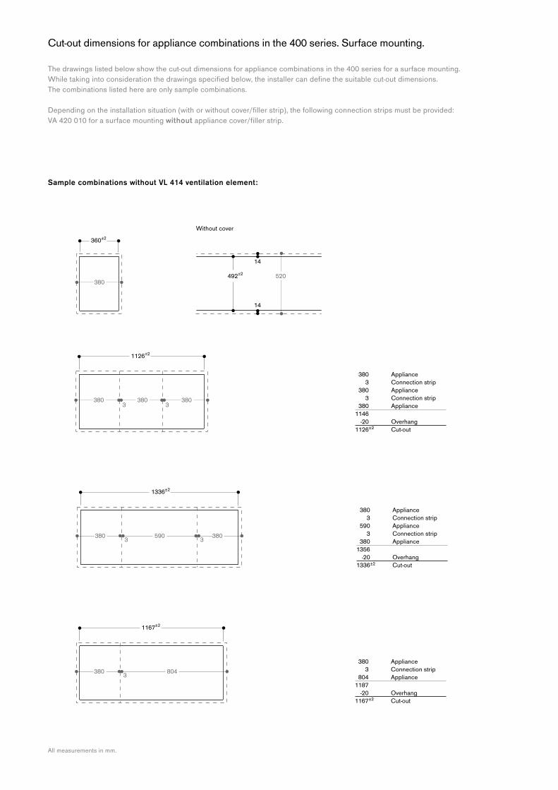
Cut-out dimensions for appliance combinations in the 400 series. Surface mounting.
The drawings listed below show the cut-out dimensions for appliance combinations in the 400 series for a surface mounting.
Whiletakingintoconsiderationthedrawingsspecifiedbelow,theinstallercandefinethesuitablecut-outdimensions. The combinations listed here are only sample combinations.
Dependingontheinstallationsituation(withorwithoutcover/fillerstrip),thefollowingconnectionstripsmustbeprovided:VA 420 010 for a surface mounting withoutappliancecover/fillerstrip.
Sample combinations without VL 414 ventilation element:
All measurements in mm.
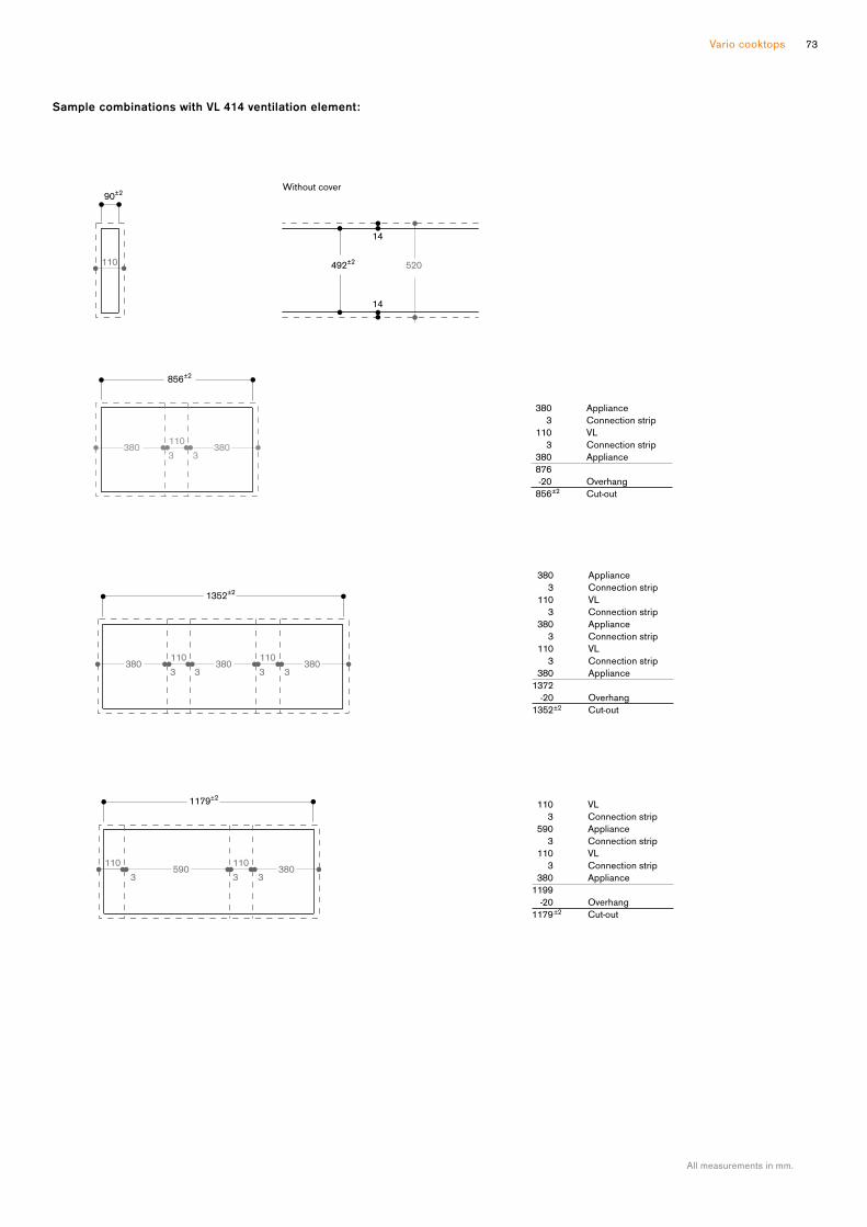
Vario cooktops 73
Sample combinations with VL 414 ventilation element:
All measurements in mm.
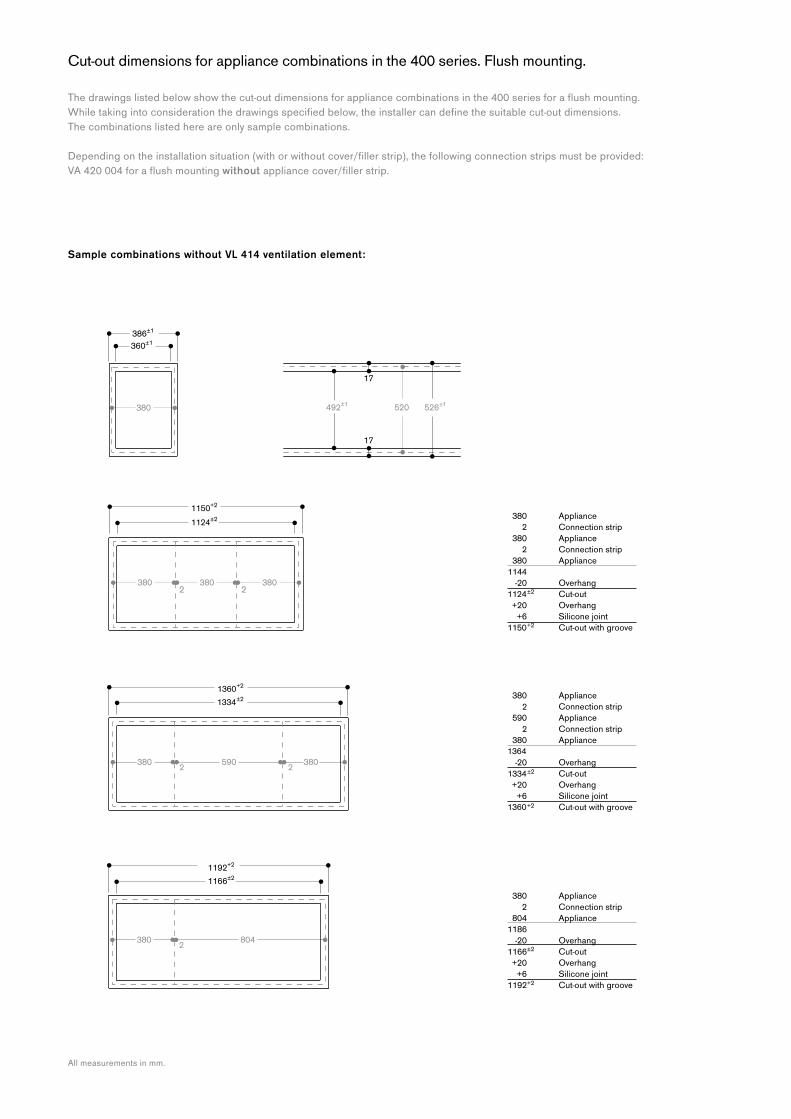
Cut-out dimensions for appliance combinations in the 400 series. Flush mounting.
Thedrawingslistedbelowshowthecut-outdimensionsforappliancecombinationsinthe400seriesforaflushmounting.Whiletakingintoconsiderationthedrawingsspecifiedbelow,theinstallercandefinethesuitablecut-outdimensions. The combinations listed here are only sample combinations.
Dependingontheinstallationsituation(withorwithoutcover/fillerstrip),thefollowingconnectionstripsmustbeprovided:VA420004foraflushmountingwithoutappliancecover/fillerstrip.
Sample combinations without VL 414 ventilation element:
All measurements in mm.
1
1
1 1
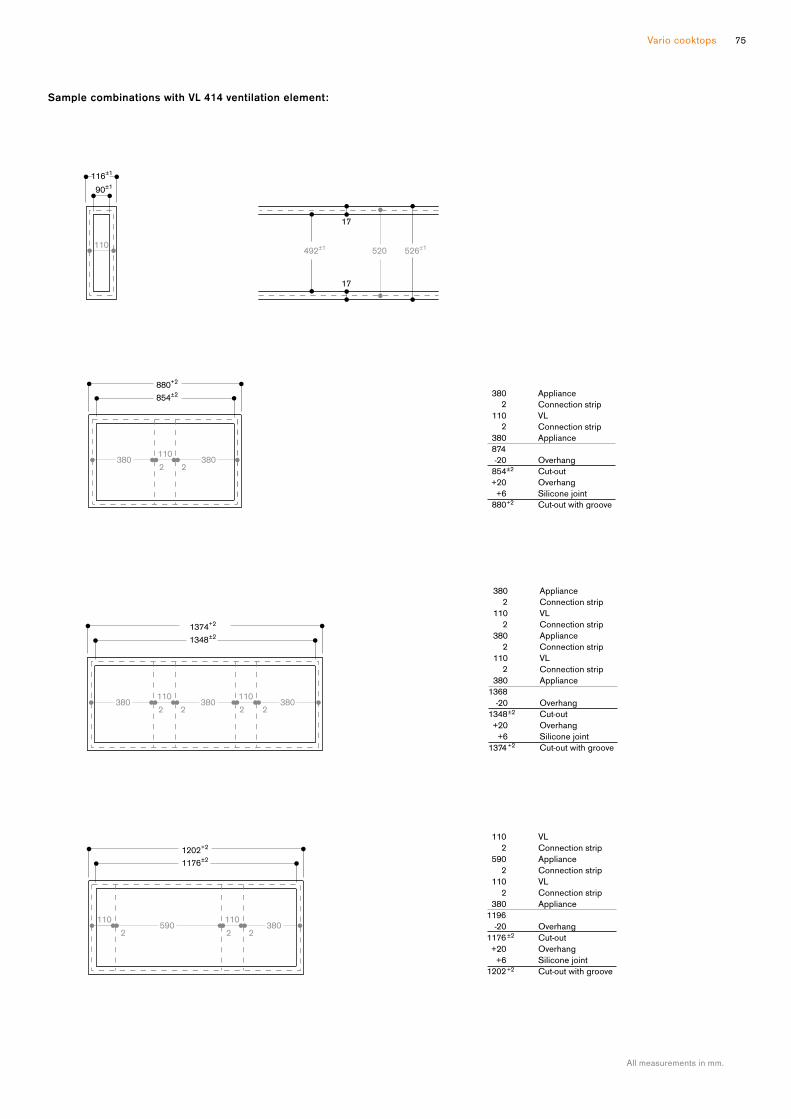
Vario cooktops 75
Sample combinations with VL 414 ventilation element:
All measurements in mm.
1
1
1 1

Cut-out dimensions for appliance combinations in the 400 series. Calculator for calculating the width of the cut-out.
Calculation of the width of the cut-out for a surface mountingExample using a combination of VI 414, VI 422, VP 414 and 2 VL 414.
Example Your combination
Total width of all appliances in mm (3x 380) + (2x 110) 1360 ……………………………………………
+Numberofconnectionstrips x3mm 4 x 3 + 12 ……………………………………………
– Lateral appliance projection (10 mm / side) 20 – 20 – 20
(A) Total width of the cut-out (in mm) 1352 +/– 2 ………………………………… +/– 2
Cut-outdepthbasedontheinstallationsituationwithorwithoutappliancecover/fillerstrip.
Calculation of the width of the cut-out for a flush mountingExample using a combination of VI 414, VI 422, VP 414 and 2 VL 414.
Example Your combination
Total width of all appliances in mm (3x 380) + (2x 110) 1.360 ……………………………………………
+ Numberofconnectionstrips x2mm 4 x 2 + 8 ……………………………………………
– Lateral appliance projection (10 mm / side) 20 – 20 – 20
(A) Total width of the cut-out (in mm) 1348 +/– 2 ………………………………… +/– 2
+ Lateral appliance projection (10 mm / side) 20 + 20 + 20
+ Silicone joint (3 mm circumference) 2 x 3 + 6 + 6
(B) Total width with groove (in mm) 1374 + 2 ………………………………… 0/+ 2
Cut-outdepthbasedontheinstallationsituationwithorwithoutappliancecover/fillerstrip.

Vario cooktops 77

V I 262 120
Black anodised control panel
in aluminium
Width 60 cm
Included in the price
1 glass scraper
Installation accessories
V V 200 010
Stainless steel connection strip
for combination with other Vario
appliances of the 200 series
V V 200 020
Black connection strip for combination
with other Vario appliances of the
200 series
Special accessories
G P 900 003
Stainless steel frying sensor pan
Non-stickcoating,ø21cm.
Varioflexinductioncooktop200seriesV I 262
— Can be combined with the
cooktops of the Vario 200 series
— Control panel for comfortable and
secure operation
Cooking zones
2xflexinductioncookingareas19x23 cm (2200 W, with booster
3700 W), linked together 38x23 cm
(3300 W, with booster 3700 W).
Handling
Electronic power control in
9 output levels.
Control knobs with illuminated ring.
Integrated control panel.
Features
Flex function for rectangular
cooking areas.
Cooking area marking.
Frying sensor function.
Pot detection.
Booster function for each cooking
area.
Safety
Residual heat indicator.
Operation indicator.
Safetyshut-off.
Planning notes
Operates with magnetic (induction)
iron pots and pans only. For an optimal
heat distribution, the use of sandwich
bottom cookware is recommended.
Appliance can be snapped into the
worktop from above.
Appliance weight: approx. 17 kg.
Please read additional planning notes
on page 86.
Please read the installation details
regarding air ducting on page 100.
Connection
Total connected load 7.4 kW.
Connecting cable 1.5 m without plug.
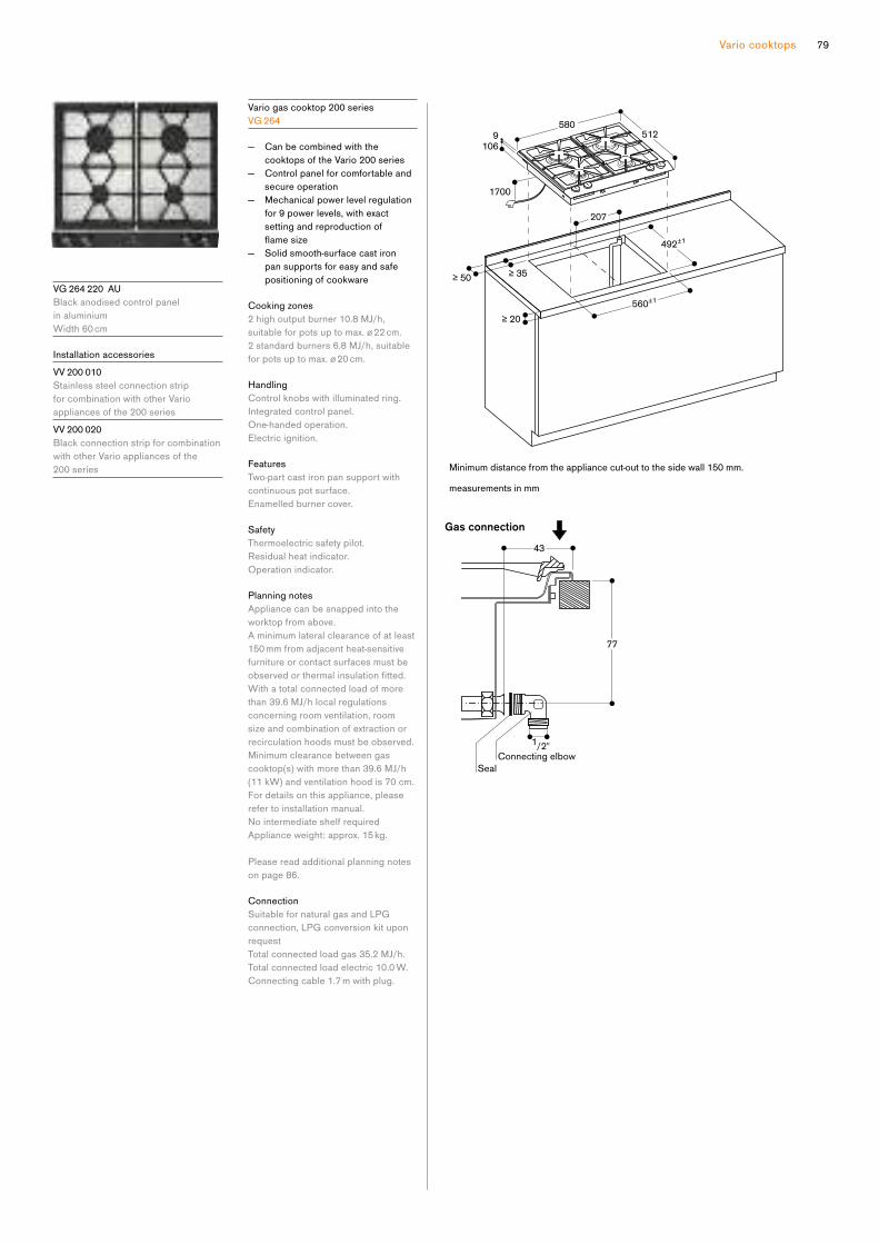
Vario cooktops 79
V G 264 220 AU
Black anodised control panel
in aluminium
Width 60 cm
Installation accessories
V V 200 010
Stainless steel connection strip
for combination with other Vario
appliances of the 200 series
V V 200 020
Black connection strip for combination
with other Vario appliances of the
200 series
Vario gas cooktop 200 series
V G 264
— Can be combined with the
cooktops of the Vario 200 series
— Control panel for comfortable and
secure operation
— Mechanical power level regulation
for 9 power levels, with exact
setting and reproduction of
flamesize — Solid smooth-surface cast iron
pan supports for easy and safe
positioning of cookware
Cooking zones
2 high output burner 10.8 MJ/h,
suitable for pots up to max. ø 22 cm.
2 standard burners 6.8 MJ/h, suitable
for pots up to max. ø 20 cm.
Handling
Control knobs with illuminated ring.
Integrated control panel.
One-handed operation.
Electric ignition.
Features
Two-part cast iron pan support with
continuous pot surface.
Enamelled burner cover.
Safety
Thermoelectric safety pilot.
Residual heat indicator.
Operation indicator.
Planning notes
Appliance can be snapped into the
worktop from above.
A minimum lateral clearance of at least
150 mm from adjacent heat-sensitive
furniture or contact surfaces must be
observedorthermalinsulationfitted.With a total connected load of more
than 39.6 MJ/h local regulations
concerning room ventilation, room
size and combination of extraction or
recirculation hoods must be observed.
Minimum clearance between gas
cooktop(s) with more than 39.6 MJ/h
(11 kW) and ventilation hood is 70 cm.
For details on this appliance, please
refer to installation manual.
NointermediateshelfrequiredAppliance weight: approx. 15 kg.
Please read additional planning notes
on page 86.
Connection
Suitable for natural gas and LPG
connection, LPG conversion kit upon
request
Total connected load gas 35.2 MJ/h.
Total connected load electric 10.0 W.
Connecting cable 1.7 m with plug.
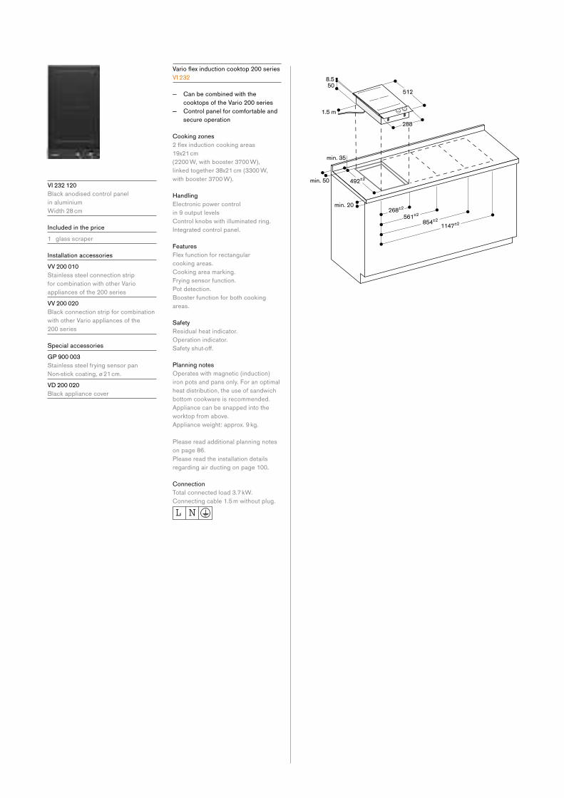
V I 232 120
Black anodised control panel
in aluminium
Width 28 cm
Included in the price
1 glass scraper
Installation accessories
V V 200 010
Stainless steel connection strip
for combination with other Vario
appliances of the 200 series
V V 200 020
Black connection strip for combination
with other Vario appliances of the
200 series
Special accessories
G P 900 003
Stainless steel frying sensor pan
Non-stickcoating,ø21cm.V D 200 020
Black appliance cover
Varioflexinductioncooktop200seriesV I 232
— Can be combined with the
cooktops of the Vario 200 series
— Control panel for comfortable and
secure operation
Cooking zones
2flexinductioncookingareas19x21 cm
(2200 W, with booster 3700 W),
linked together 38x21 cm (3300 W,
with booster 3700 W).
Handling
Electronic power control
in 9 output levels
Control knobs with illuminated ring.
Integrated control panel.
Features
Flex function for rectangular
cooking areas.
Cooking area marking.
Frying sensor function.
Pot detection.
Booster function for both cooking
areas.
Safety
Residual heat indicator.
Operation indicator.
Safetyshut-off.
Planning notes
Operates with magnetic (induction)
iron pots and pans only. For an optimal
heat distribution, the use of sandwich
bottom cookware is recommended.
Appliance can be snapped into the
worktop from above.
Appliance weight: approx. 9 kg.
Please read additional planning notes
on page 86.
Please read the installation details
regarding air ducting on page 100.
Connection
Total connected load 3.7 kW.
Connecting cable 1.5 m without plug.

Vario cooktops 81
V G 231 220 AU
Black anodised control panel
in aluminium
Width 28 cm
Wok burner with up to 18 MJ/h
Included in the price
1 wok attachment ring
Installation accessories
V V 200 010
Stainless steel connection strip
for combination with other Vario
appliances of the 200 series
V V 200 020
Black connection strip for combination
with other Vario appliances of the
200 series
Special accessories
V D 200 020
Black appliance cover
W P 400 001
Wok pan made of multiple-layer
material
With round bottom and handle,
ø 36 cm, 6 litres, height 10 cm.
Vario gas wok 200 series
V G 231
— Can be combined with the
cooktops of the Vario 200 series
— Control panel for comfortable and
secure operation
— Mechanical power level regulation
for 9 power levels, with exact
setting and reproduction of
flamesize — Multi-ring burner of solid, heat-
resistant brass as used
in professional kitchen
Cooking zones
1 multi-ring wok burner
18 MJ/h, suitable for pots up
to max. ø 30 cm.
Handling
Control knobs with illuminated ring.
Integrated control panel.
One-handed operation.
Electric ignition.
To close the cover, the cast iron pan
support can be easily reversed.
Features
Cast iron pan support.
Brass burner ring.
Safety
Thermoelectric safety pilot.
Residual heat indicator.
Operation indicator.
Planning notes
Appliance can be snapped into the
worktop from above.
A minimum clearance of at least
150 mm from adjacent heat-sensitive
furniture or contact surfaces must be
observedorthermalinsulationfitted.With a total connected load of more
than 39.6 MJ/h local regulations
concerning room ventilation, room
size and combination of extraction or
recirculation hoods must be observed.
Minimum clearance between gas
cooktop(s) with more than 39.6 MJ/h
(11 kW) and ventilation hood is 70 cm.
For details on this appliance, please
refer to installation manual.
Appliance weight: approx. 10 kg.
Please read additional planning notes
on page 86.
Connection
Suitable for natural gas and LPG
connection, includes LPG conversion
kit
Total connected load gas 18.0 MJ/h.
Total connected load electric 10.0 W.
Connecting cable 1.7 m with plug.

V G 232 220 AU
Black anodised control panel
in aluminium
Width 28 cm
Installation accessories
V V 200 010
Stainless steel connection strip
for combination with other Vario
appliances of the 200 series
V V 200 020
Black connection strip for combination
with other Vario appliances of the
200 series
Special accessories
V D 200 020
Black appliance cover
Vario gas cooktop 200 series
V G 232
— Can be combined with the
cooktops of the Vario 200 series
— Control panel for comfortable and
secure operation
— Mechanical power level regulation
for 9 power levels, with exact
setting and reproduction of
flamesize — Solid smooth-surface cast iron
pan supports for easy and safe
positioning of cookware
Cooking zones
1 high output burner 10.8 MJ/h,
suitable for pots up to max. ø 22 cm.
1 standard burner 6.8 MJ/h, suitable
for pots up to max. ø 20 cm.
Handling
Control knobs with illuminated ring.
Integrated control panel.
One-handed operation.
Electric ignition.
Features
Cast iron pan support with continuous
pot surface.
Enamelled burner cover.
Safety
Thermoelectric safety pilot.
Residual heat indicator.
Operation indicator.
Planning notes
Appliance can be snapped into the
worktop from above.
A minimum clearance of at least
150 mm from adjacent heat-sensitive
furniture or contact surfaces must be
observedorthermalinsulationfitted.With a total connected load of more
than 39.6 MJ/h local regulations
concerning room ventilation, room
size and combination of extraction or
recirculation hoods must be observed.
Minimum clearance between gas
cooktop(s) with more than 39.6 MJ/h
(11 kW) and ventilation hood is 70 cm.
For details on this appliance, please
refer to installation manual.
Appliance weight: approx. 8 kg.
Please read additional planning notes
on page 86.
Connection
Suitable for natural gas and LPG
connection, includes LPG conversion
kit
Total connected load gas 17.6 MJ/h.
Total connected load electric 10.0 W.
Connecting cable 1.7 m with plug.
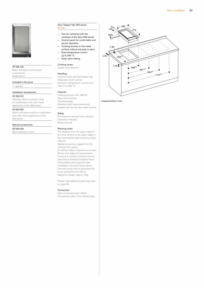
Vario cooktops 83
V P 230 120
Black anodised control panel
in aluminium
Width 28 cm
Included in the price
1 spatula
Installation accessories
V V 200 010
Stainless steel connection strip
for combination with other Vario
appliances of the 200 series
V V 200 020
Black connection strip for combination
with other Vario appliances of the
200 series
Special accessories
V D 200 020
Black appliance cover
Vario Teppan Yaki 200 series
V P 230
— Can be combined with the
cooktops of the Vario 200 series
— Control panel for comfortable and
secure operation
— Cooking directly on the metal
surface, without any pots or pans
— Exact temperature control
up to 240 °C
— Keep warm setting
Cooking zones
Usable area: 844 cm².
Handling
Control knobs with illuminated ring.
Integrated control panel.
Electronic temperature control from
140 °C to 240 °C.
Features
Heating element with 1800 W.
Keep warm setting.
Cleaning stage.
Stainless steel frame seamlessly
welded with the stainless steel surface.
Safety
Pre-heat and residual heat indicator.
Operation indicator.
Safetyshut-off.
Planning notes
The distance from the upper edge of
the work surface to the upper edge of
the intermediate shelf must be at least
150 mm.
Appliance can be snapped into the
worktop from above.
A minimum lateral clearance of at least
30 mm from adjacent heat-sensitive
furniture or contact surfaces must be
observedorthermalinsulationfitted.Intermediate shelf required; after
installation, this shelf must only be
removed using tools to guarantee the
touch protection from below.
Appliance weight: approx. 9 kg.
Please read additional planning notes
on page 86.
Connection
Total connected load 1.8 kW.
Connecting cable 1.8 m without plug.
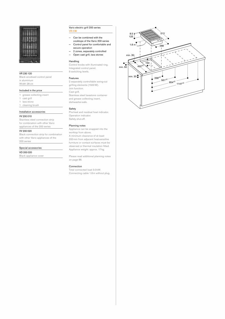
V R 230 120
Black anodised control panel
in aluminium
Width 28 cm
Included in the price
1 grease collecting insert
1 cast grill
1 lava stone
1 cleaning brush
Installation accessories
V V 200 010
Stainless steel connection strip
for combination with other Vario
appliances of the 200 series
V V 200 020
Black connection strip for combination
with other Vario appliances of the
200 series
Special accessories
V D 200 020
Black appliance cover
Vario electric grill 200 series
V R 230
— Can be combined with the
cooktops of the Vario 200 series
— Control panel for comfortable and
secure operation
— 2 zones, separately controlled
— Open cast grill, lava stones
Handling
Control knobs with illuminated ring.
Integrated control panel.
9 switching levels.
Features
2 separately controllable swing-out
grilling elements (1500 W).
Join function.
Cast grill.
Stainless steel lavastone container
and grease collecting insert,
dishwasher-safe.
Safety
Pre-heat and residual heat indicator.
Operation indicator.
Safetyshut-off.
Planning notes
Appliance can be snapped into the
worktop from above.
A minimum clearance of at least
200 mm from adjacent heat-sensitive
furniture or contact surfaces must be
observedorthermalinsulationfitted.Appliance weight: approx. 17 kg.
Please read additional planning notes
on page 86.
Connection
Total connected load 3.0 kW.
Connecting cable 1.8 m without plug.
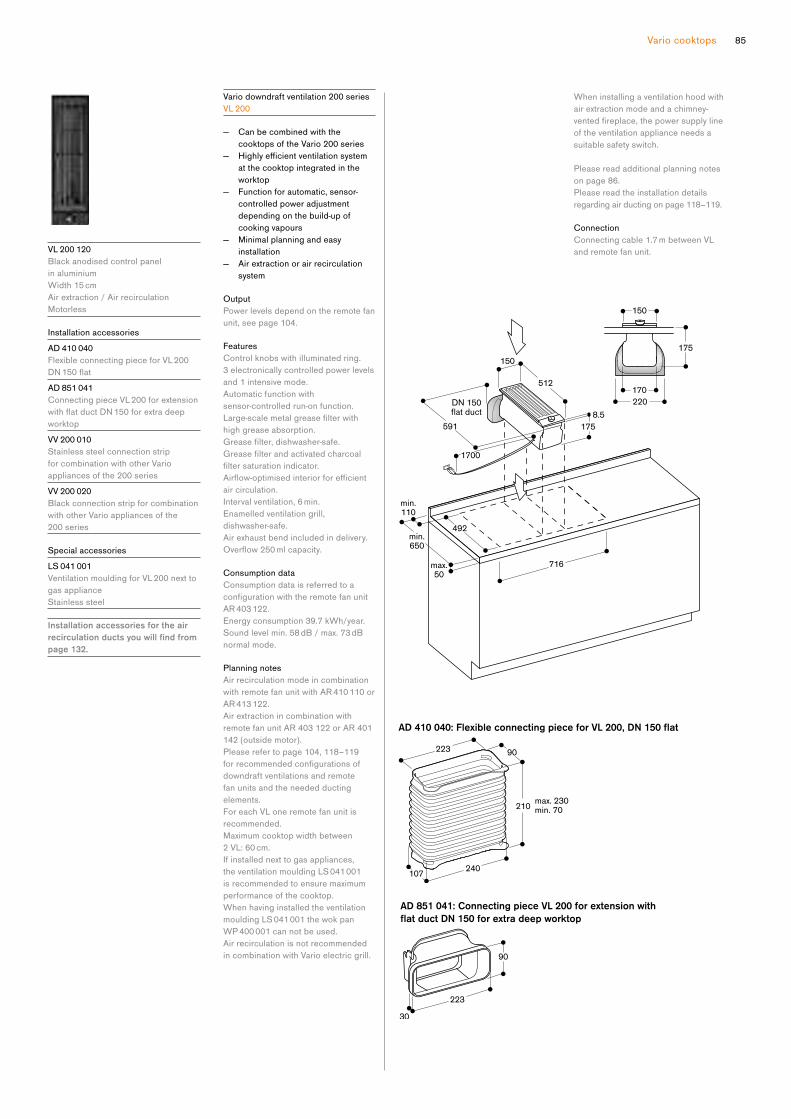
Vario cooktops 85
AD 851 041: Connecting piece VL 200 for extension with
flat duct DN 150 for extra deep worktop
AD 410 040: Flexible connecting piece for VL 200, DN 150 flat
V L 200 120
Black anodised control panel
in aluminium
Width 15 cm
Air extraction / Air recirculation
Motorless
Installation accessories
A D 410 040
Flexible connecting piece for VL 200
DN150flatA D 851 041
Connecting piece VL 200 for extension
withflatductDN150forextradeepworktop
V V 200 010
Stainless steel connection strip
for combination with other Vario
appliances of the 200 series
V V 200 020
Black connection strip for combination
with other Vario appliances of the
200 series
Special accessories
L S 041 001
Ventilation moulding for VL 200 next to
gas appliance
Stainless steel
Installation accessories for the air recirculation ducts you will find from page 132.
Vario downdraft ventilation 200 series
V L 200
— Can be combined with the
cooktops of the Vario 200 series
— Highlyefficientventilationsystem at the cooktop integrated in the
worktop
— Function for automatic, sensor-
controlled power adjustment
depending on the build-up of
cooking vapours
— Minimal planning and easy
installation
— Air extraction or air recirculation
system
Output
Power levels depend on the remote fan
unit, see page 104.
Features
Control knobs with illuminated ring.
3 electronically controlled power levels
and 1 intensive mode.
Automatic function with
sensor-controlled run-on function.
Large-scalemetalgreasefilterwithhigh grease absorption.
Greasefilter,dishwasher-safe.Greasefilterandactivatedcharcoalfiltersaturationindicator.Airflow-optimisedinteriorforefficientair circulation.
Interval ventilation, 6 min.
Enamelled ventilation grill,
dishwasher-safe.
Air exhaust bend included in delivery.
Overflow250mlcapacity.
Consumption data
Consumption data is referred to a
configurationwiththeremotefanunitAR 403 122.
Energy consumption 39.7 kWh/year.
Sound level min. 58 dB / max. 73 dB
normal mode.
Planning notes
Air recirculation mode in combination
with remote fan unit with AR 410 110 or
AR 413 122.
Air extraction in combination with
remote fan unit AR 403 122 or AR 401
142 (outside motor).
Please refer to page 104, 118–119
forrecommendedconfigurationsofdowndraft ventilations and remote
fan units and the needed ducting
elements.
For each VL one remote fan unit is
recommended.
Maximum cooktop width between
2 VL: 60 cm.
If installed next to gas appliances,
the ventilation moulding LS 041 001
is recommended to ensure maximum
performance of the cooktop.
When having installed the ventilation
moulding LS 041 001 the wok pan
WP 400 001 can not be used.
Air recirculation is not recommended
in combination with Vario electric grill.
When installing a ventilation hood with
air extraction mode and a chimney-
ventedfireplace,thepowersupplylineof the ventilation appliance needs a
suitable safety switch.
Please read additional planning notes
on page 86.
Please read the installation details
regarding air ducting on page 118–119.
Connection
Connecting cable 1.7 m between VL
and remote fan unit.
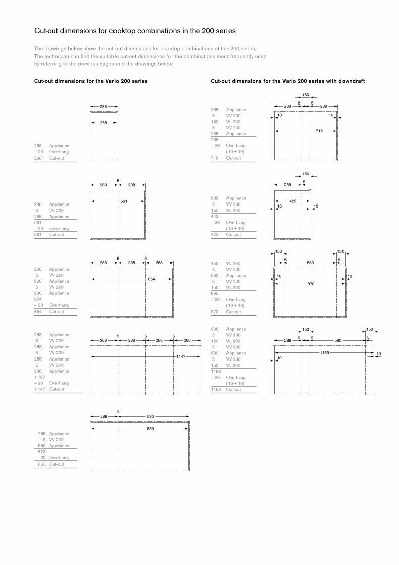
55
1010
150 150
580
870
5 5
10
150
580288
1163
5
288 580
853
288 288
561
5
288 288
5
288
854
5
288 288
5
288
1147
5
288
5 5
10
150
288
268
2885
1010
150
423
28855
10 10
150
716
288
The drawings below show the cut-out dimensions for cooktop combinations of the 200 series.
Thetechniciancanfindthesuitablecut-outdimensionsforthecombinationsmostfrequentlyused by referring to the previous pages and the drawings below.
Cut-out dimensions for the Vario 200 series Cut-out dimensions for the Vario 200 series with downdraft
288 Appliance
5 VV 200
288 Appliance
581
– 20 Overhang
561 Cut-out
288 Appliance
5 VV 200
288 Appliance
5 VV 200
288 Appliance
874
– 20 Overhang
854 Cut-out
288 Appliance
5 VV 200
288 Appliance
5 VV 200
288 Appliance
5 VV 200
288 Appliance
1.167
– 20 Overhang
1.147 Cut-out
288 Appliance
5 VV 200
150 VL 200
5 VV 200
580 Appliance
5 VV 200
150 VL 200
1183
– 20 Overhang
(10 + 10)
1163 Cut-out
288 Appliance
5 VV 200
150 VL 200
5 VV 200
288 Appliance
736
– 20 Overhang
(10 + 10)
716 Cut-out
150 VL 200
5 VV 200
580 Appliance
5 VV 200
150 VL 200
890
– 20 Overhang
(10 + 10)
870 Cut-out
288 Appliance
5 VV 200
580 Appliance
873
– 20 Overhang
853 Cut-out
Cut-out dimensions for cooktop combinations in the 200 series
288 Appliance
– 20 Overhang
268 Cut-out
288 Appliance
5 VV 200
150 VL 200
443
– 20 Overhang
(10 + 10)
423 Cut-out

Vario cooktops 87
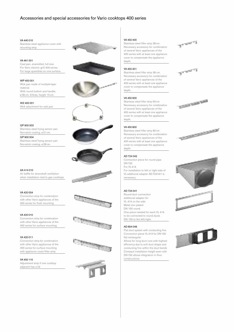
Accessories and special accessories for Vario cooktops 400 series
V A 440 010
Stainless steel appliance cover with
mounting strip
V A 461 001
Cast pan, enamelled, full size
For Vario electric grill 400 series.
For large quantities on one surface.
W P 400 001
Wok pan made of multiple-layer
material
With round bottom and handle,
ø 36 cm, 6 litres, height 10 cm.
W Z 400 001
Wok attachment for wok pan
G P 900 003
Stainless steel frying sensor pan
Non-stickcoating,ø21cm.G P 900 004
Stainless steel frying sensor pan
Non-stickcoating,ø28cm.
A A 414 010
Airbafflefordowndraftventilationwhen installation next to gas cooktops
V A 420 004
Connection strip for combination
with other Vario appliances of the
400seriesforflushmounting
V A 420 010
Connection strip for combination
with other Vario appliances of the
400 series for surface mounting
V A 420 011
Connection strip for combination
with other Vario appliances of the
400 series for surface mounting
withappliancecover/fillerstrip
V A 450 110
Adjustment strip if one cooktop
adjacent has a lid
V A 450 400
Stainlesssteelfillerstrip38cmNecessaryaccessoryforcombinationof several Vario appliances of the
400 series with at least one appliance
cover to compensate the appliance
depth.
V A 450 401
Stainlesssteelfillerstrip38cmNecessaryaccessoryforcombinationof several Vario appliances of the
400 series with at least one appliance
cover to compensate the appliance
depth.
V A 450 600
Stainlesssteelfillerstrip60cmNecessaryaccessoryforcombinationof several Vario appliances of the
400 series with at least one appliance
cover to compensate the appliance
depth.
V A 450 800
Stainlesssteelfillerstrip80cmNecessaryaccessoryforcombinationof several Vario appliances of the
400 series with at least one appliance
cover to compensate the appliance
depth.
A D 724 042
Connection piece for round pipe
DN150For VL 414
For installation to left or right side of
VL additional adapter AD 724 041 is
necessary.
A D 724 041
Round duct connection
additional adaptor for
VL 414 on the side
Metal zinc plated
DN150roundOne piece needed for each VL 414
to be connected to round ducts
DN150totheleft/right.
A D 854 046
FlatductsystemwithconductingfinsConnectionpieceVL414forDN150flatrectangularAllows for long duct runs with highest
efficiencyduetosoftductshapeandconductingfinswithintheductbendsCompact installation height even with
DN150allowsintegrationinfloorconstructions

Vario cooktops 89
Accessories and special accessories for Vario cooktops 200 series
V D 200 020
Black appliance cover
L S 041 001
AirbaffleforVL200nexttogasappliance
V V 200 010
Stainless steel connection strip
for combination with other Vario
appliances of the 200 series.
V V 200 020
Black connection strip for combination
with other Vario appliances of the
200 series.
W P 400 001
Wok pan made of multiple-layer
material
With round bottom and handle,
ø 36 cm, 6 litres, height 10 cm.
W Z 400 001
Wok attachment for wok pan
G P 900 003
Stainless steel frying sensor pan
Non-stickcoating,ø21cm.
A D 410 040
Flexible connecting piece for VL 200
DN150flat
A D 851 041
Connecting piece VL 200 for extension
withflatductDN150forextradeepworktop

The cooktops
Gas cooktops 92
Induction cooktops 94
Installation notes for induction cooktops 100
Accessories | special accessories 101
91
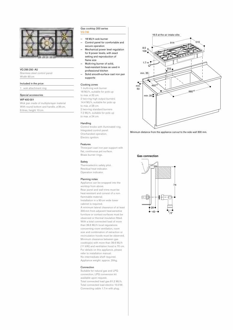
V G 295 250 AU
Stainless steel control panel
Width 90 cm
Included in the price
1 wok attachment ring
Special accessories
W P 400 001
Wok pan made of multiple-layer material
With round bottom and handle, ø 36 cm,
6 litres, height 10 cm.
Gas cooktop 200 series
V G 295
— 18 MJ/h wok burner
— Control panel for comfortable and
secure operation
— Mechanical power level regulation
for 9 power levels, with exact
setting and reproduction of
flamesize — Multi-ring burner of solid,
heat-resistant brass as used in
professional kitchen
— Solid smooth-surface cast iron pan
supports
Cooking zones
1 multi-ring wok burner
18 MJ/h, suitable for pots up
to max. ø 32 cm.
2 two-ring high output burners
14.4 MJ/h, suitable for pots up
to max. ø 28 cm.
2 two-ring standard burners
7.2 MJ/h, suitable for pots up
to max. ø 24 cm.
Handling
Control knobs with illuminated ring.
Integrated control panel.
One-handed operation.
Electric ignition.
Features
Three-part cast iron pan support with
flat,continuouspotsurface.Brass burner rings.
Safety
Thermoelectric safety pilot.
Residual heat indicator.
Operation indicator.
Planning notes
Appliance can be snapped into the
worktop from above.
Rear panel and wall trims must be
heat-resistant and consist of a non-
flammablematerial.Installation in a 90 cm wide lower
cabinet is required.
A minimum lateral clearance of at least
300 mm from adjacent heat-sensitive
furniture or contact surfaces must be
observedorthermalinsulationfitted.With a total connected load of more
than 39.6 MJ/h local regulations
concerning room ventilation, room
size and combination of extraction or
recirculation hoods must be observed.
Minimum clearance between gas
cooktop(s) with more than 39.6 MJ/h
(11 kW) and ventilation hood is 70 cm.
For details on this appliance, please
refer to installation manual.
Nointermediateshelfrequired.Appliance weight: approx. 29 kg.
Connection
Suitable for natural gas and LPG
connection, LPG conversion kit
available upon request.
Total connected load gas 61.2 MJ/h.
Total connected load electric 10.0 W.
Connecting cable 1.7 m with plug.
min.
50
min. 35
1.7 m
8.5
16.5 at the air intake slits
Minimum distance from the appliance cut-out to the side wall 300 mm.
min. 20
885±2
492±2
106
914 510
203
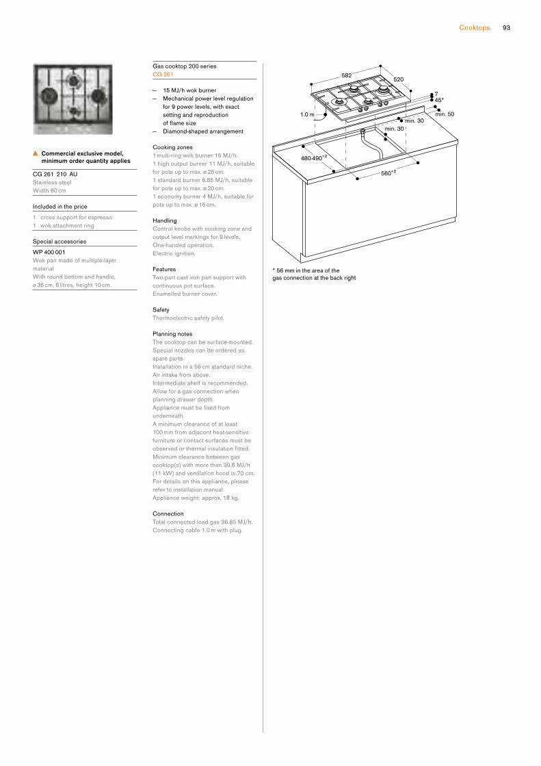
93Cooktops
Commercial exclusive model,
minimum order quantity applies
CG 261 210 AU
Stainless steel
Width 60 cm
Included in the price
1 cross support for espresso
1 wok attachment ring
Special accessories
W P 400 001
Wok pan made of multiple-layer
material
With round bottom and handle,
ø 36 cm, 6 litres, height 10 cm.
Gas cooktop 200 series
C G 261
— 15 MJ/h wok burner
— Mechanical power level regulation
for 9 power levels, with exact
setting and reproduction
offlamesize — Diamond-shaped arrangement
Cooking zones
1 multi-ring wok burner 15 MJ/h.
1 high output burner 11 MJ/h, suitable
for pots up to max. ø 26 cm.
1 standard burner 6.85 MJ/h, suitable
for pots up to max. ø 20 cm.
1 economy burner 4 MJ/h, suitable for
pots up to max. ø 16 cm.
Handling
Control knobs with cooking zone and
output level markings for 9 levels.
One-handed operation.
Electric ignition.
Features
Two-part cast iron pan support with
continuous pot surface.
Enamelled burner cover.
Safety
Thermoelectric safety pilot.
Planning notes
The cooktop can be surface-mounted.
Special nozzles can be ordered as
spare parts.
Installation in a 56 cm standard niche.
Air intake from above.
Intermediate shelf is recommended.
Allow for a gas connection when
planning drawer depth.
Appliancemustbefixedfromunderneath.
A minimum clearance of at least
100 mm from adjacent heat-sensitive
furniture or contact surfaces must be
observedorthermalinsulationfitted.Minimum clearance between gas
cooktop(s) with more than 39.6 MJ/h
(11 kW) and ventilation hood is 70 cm.
For details on this appliance, please
refer to installation manual.
Appliance weight: approx. 18 kg.
Connection
Total connected load gas 36.85 MJ/h.
Connecting cable 1.0 m with plug.
C X 492 101
Black glass ceramic
Frameless
Width 90 cm
Included in the price
1 wireless plug-in core temperature
probe for cooktop
Special accessories
C A 060 300
Cooking sensor for temperature
regulation within pots
G N 232 110
Teppan Yaki plate made of multi ply
material,
GN1/1
For full surface induction cooktops.
Full surface induction cooktop
400 series
CX 492
— One single big cooking surface
— Free positioning of cookware
— All sizes and formats of cookware
can be used
— TFT touch display for an intuitive
control of all functions
— Cooking sensor function for
temperature control in pots
— Professional cooking functions
— Max. power output for big
cookware of up to 5.5 kW
— Framelessforflushmounting
Cooking zones
One unique cooking surface of
3200 cm².
Up to 6 items of cookware can be
placed simultaneously on the cooktop.
Handling
Easy to use colour graphic TFT touch
display with use indications.
Electronic power control in 17 output
levels.
Features
Cooking sensor function.
Professional cooking function.
Dynamic cooking function.
Teppan Yaki function.
Booster function for pots.
Booster function for pans.
Keep warm function.
Individual pot detection.
Cooking timer for each cooking
position.
Stopwatch.
Short-term timer.
Information key with use indicators.
Power management.
Cooktop-based ventilation control
(with suitable hood).
Home network integration for digital
services (Home Connect) either via
cableconnectionLAN(recommended)or wireless via WiFi. For further
information please check:
home-connect.com
Safety
Main switch.
Residual heat indication.
Child lock.
Safetyshut-off.Pause function.
Planning notes
Operates with magnetic (induction)
iron pots and pans only. For an optimal
heat distribution, the use of sandwich
bottom cookware is recommended.
The wok pan WP 400 001 cannot be
used with this appliance.
Installation is possible in worktops
made of stone, synthetics or solid
wood. Heat resistance and watertight
sealing of the cut edges must
be observed. Concerning other
materials please consult the worktop
manufacturer.
The bearing capacity and stability, in
the case of thin worktops in particular,
must be supported using suitable
substructures. Take into account the
appliance weight and additional loads.
The groove must be continuous and
even, so that uniform placing of the
appliance on the gasket is ensured.
Do not use discontinuous lining.
Appliancemustbefixedfromunderneath.
Joint width may vary due to dimensional
tolerances of the glass ceramic
cooktop and the worktop cut-out.
Appliance weight: approx. 31 kg.
Please read the installation details
regarding air ducting on page 100.
Connection
Total connected load 7.4 kW.
Connecting cable 1.5 m without plug.
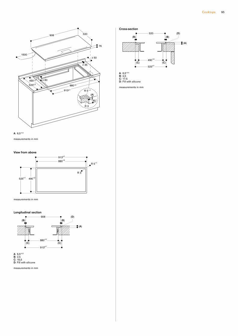
95Cooktops
A: 6,5+0,5
R 5 +1
R 3
measurements in mm
1500≥ 50
≥ 35
≥ 80525±1
520908
913±1
880+2
490+2
76
(A)
90°
Cross-section
A: 6,5+0,5
B: 2,5C: 17,5 D: Fill with silicone
measurements in mm
490+2
525±1
520 (D)
(C)(C)
(A)
(B)(B)
Longitudinal section
A: 6,5+0,5
B: 2,5 C: 16,5D: Fill with silicone
measurements in mm
(A)
(B)(B)
(C) (C)
(D)
880+2
908
913±1
View from above
R 3
R 5+1
measurements in mm
525±1
490+2
913±1
880+2

C X 482 111
Black glass ceramic
Stainless steel frame
Width 80 cm
Included in the price
1 wireless plug-in core temperature
probe for cooktop
Installation accessories
V A 420 004
Connection strip for combination with
other Vario appliances of the
400seriesforflushmountingV A 420 010
Connection strip for combination with
other Vario appliances of the
400 series for surface mounting
Special accessories
C A 060 300
Cooking sensor for temperature
regulation within pots
G N 232 110
Teppan Yaki plate made of multi ply
material,
GN1/1
For full surface induction cooktops.
Full surface induction cooktop
400 series
CX 482
— One single big cooking surface
— Free positioning of cookware
— All sizes and formats of cookware
can be used
— TFT touch display for an intuitive
control of all functions
— Cooking sensor function for
temperature control in pots
— Professional cooking functions
— Max. power output for big
cookware of up to 5.5 kW
— Precision crafted 3 mm stainless
steel
— For surface mounting with a visible
edgeorforflushmounting — Can be combined perfectly with
other Vario appliances of the
400 series
Cooking zones
One unique cooking surface of
2750 cm².
Up to 5 items of cookware can be
placed simultaneously on the cooktop.
Handling
Easy to use colour graphic TFT touch
display with use indications.
Electronic power control in 17 output
levels.
Features
Cooking sensor function.
Professional cooking function.
Dynamic cooking function.
Teppan Yaki function.
Booster function for pots.
Booster function for pans.
Keep warm function.
Individual pot detection.
Cooking timer for each cooking
position.
Stopwatch.
Short-term timer.
Information key with use indicators.
Power management.
Cooktop-based ventilation control
(with suitable hood).
Home network integration for digital
services (Home Connect) either via
cableconnectionLAN(recommended)or wireless via WiFi. For further
information please check:
home-connect.com
Safety
Main switch.
Residual heat indication.
Child lock.
Safetyshut-off.Pause function.
Planning notes
Depending on the type of installation
(surface-mountedorflush-mounted),thespecificdefinitionofthecut-outmust be observed.
If combining several Vario appliances
of the 400 series, a connection strip
VA 420 must be placed between the
appliances. Depending on the type
of installation, the corresponding
connection strip must be provided.
The bearing capacity and stability, in
the case of thin worktops in particular,
must be supported using suitable
substructures. Take into account the
appliance weight and additional loads.
Additionalinstructionsforflushmounting:
Installation is possible in worktops
made of stone, synthetics or solid
wood. Heat resistance and watertight
sealing of the cut edges must
be observed. Concerning other
materials please consult the worktop
manufacturer.
The groove must be continuous and
even, so that uniform placing of the
appliance on the gasket is ensured.
Do not use discontinuous lining.
The joint width may vary due to size
tolerances of the combinations and of
the worktop cut-out.
Please read additional planning notes
on page 72–77.
If installing several appliances in
individual cut-outs allow for a division
bar of minimum 50 mm between the
individual cut-outs.
Operates with magnetic (induction)
iron pots and pans only. For an optimal
heat distribution, the use of sandwich
bottom cookware is recommended.
The wok pan WP 400 001 cannot be
used with this appliance.
Appliance can be snapped into the
worktop from above.
Appliance weight: approx. 27 kg.
Please read the installation details
regarding air ducting on page 100.
Connection
Total connected load 7.4 kW.
Connecting cable 1.5 m without plug.

97Cooktops
Cross-section
A: 3.5-0.5
B: Fill with silicone
measurements in mm
492±1
524+1
2 2
520 (B)
(A)
measurements in mm
492±1
784±1
520804
653
≥ 50 ≥ 70
90°
R 3
1500
A: 3.5-0.5
measurements in mm
(A)
90°
492±1 524+1
+1
808+1
784±1
520804
1500
68
≥ 50 ≥ 70
3
R 3
R 4
View from above
measurements in mm
524+1
492±1
808+1
784±1
R 4+1
R 3
Longitudinal section
A: 3.5-0.5
B: Fill with silicone
measurements in mm
(B)
(A)
784±1
804
2 2
808+1

C I 292 112
Stainless steel frame
Width 90 cm
Special accessories
C A 051 300
Teppan Yaki plate made of multi ply
material
Forflexinductioncooktop.C A 052 300
Griddle plate in cast aluminium
Non-stick.Forflexinductioncooktop.C A 060 300
Cooking sensor for temperature
regulation within pots
C A 230 100
Black magnetic knob for induction
cooktop 200 series
Stainless steel knob with black
coating.
G P 900 003
Stainless steel frying sensor pan
Non-stickcoating,ø21cm.G P 900 004
Stainless steel frying sensor pan
Non-stickcoating,ø28cm.
Flex induction cooktop 200 series
C I 292
— Sturdy stainless steel frame
— Flex function for combining the
rectangular cooking areas
— Free positioning of cookware
inside combined cooking areas
— Professional cooking function
for splitting the cooktop into
predefinedheatareas — Cooking sensor function for
temperature control in pots
— Frying sensor function for
temperature control in pans
— Large cooking zone for pots up to
ø 32 cm
— Twist-Pad control with removable
magnetic knob
— Easy control of all functions with
bicoloured display
Cooking zones
2flexinductioncookingareas19x23 cm (2200 W, with booster
3700 W), linked together 38x23 cm
(3300 W, with booster 3700 W).
2flexinductioncookingareas19x23 cm (2200 W, with booster
3700 W), linked together 38x23 cm
(3300 W, with booster 3700 W).
1 induction cooking zone ø 21 cm
(2200 W, with booster 3700 W),
automatically switches to ø 26 cm
(2600 W, with booster 3700 W) and
to ø 32 cm (3300 W, with booster
3700 W).
Handling
Twist-Pad control with removable
magnetic knob.
User friendly control with bicoloured
display (white / orange).
Cooking zone and cooking area
marking.
Electronic power control in 17 output
levels.
Features
Flex function for rectangular cooking
areas.
Professional cooking function.
Cooking sensor function (in use with
cooking sensor CA 060 300).
Frying sensor function.
Booster function for pots.
Booster function for pans.
Keep warm function.
Stopwatch.
Cooking timer for up to 99 minutes.
Short-term timer.
Options menu.
Power management.
Cooktop-based ventilation control
(with suitable hood).
Home network integration for digital
services (Home Connect) either via
cableconnectionLAN(recommended)or wireless via WiFi. For further
information please check:
home-connect.com
Safety
Main switch.
Operation indicator.
Pot detection.
2-stage residual heat indication.
Child lock.
Safetyshut-off.
Planning notes
Operates with magnetic (induction)
iron pots and pans only. For an optimal
heat distribution, the use of sandwich
bottom cookware is recommended.
The wok pan WP 400 001 cannot be
used with this appliance.
Appliancemustbefixedfromunderneath.
Appliance weight: approx. 27 kg.
Please read the installation details
regarding air ducting on page 100.
Connection
Total connected load 11.1 kW.
Connecting cable 1.5 m without plug.

99Cooktops
A:
R 3
Please check the installation manual in case the worktop depth is below 600 mm.
measurements in mm
≥ 50
≥ 60
≥ 35
1500
≥ 600 (A)
490+2
520908
880+2
553
90°
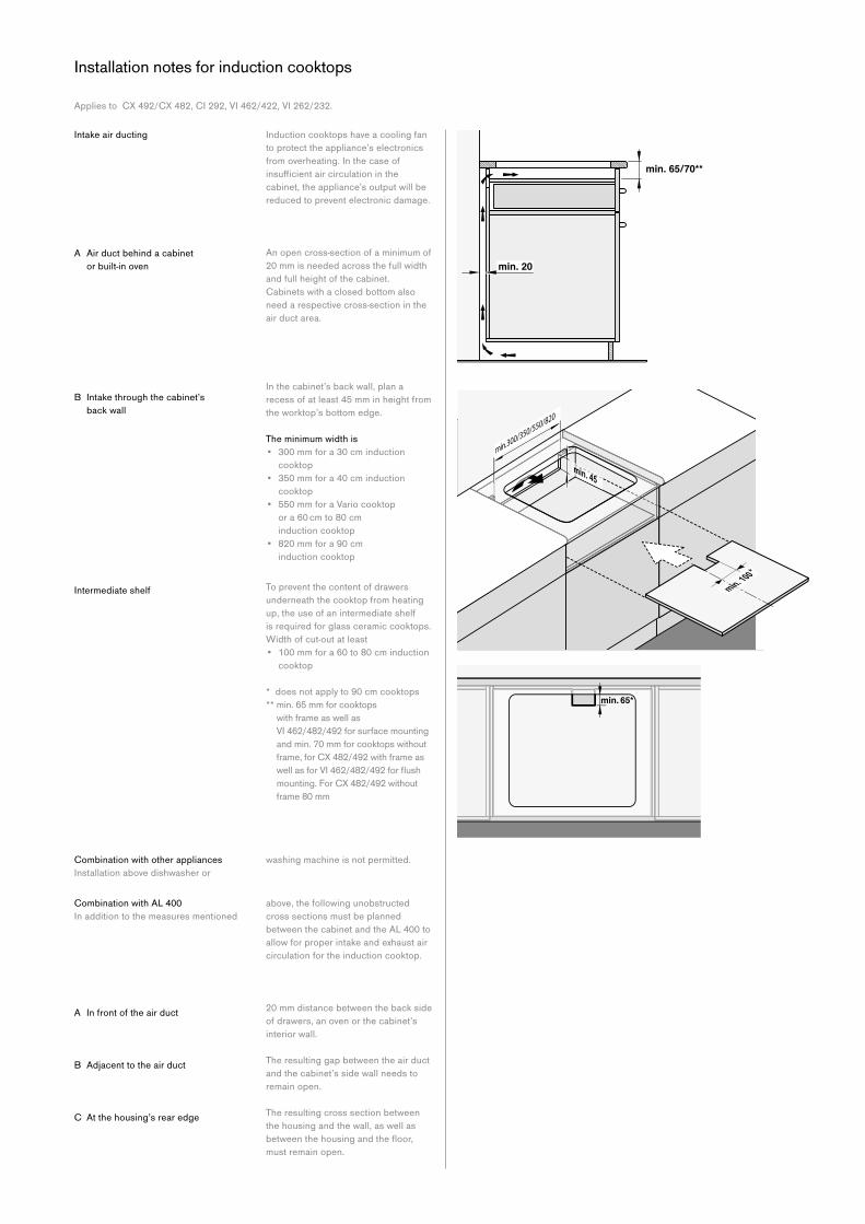
A Air duct behind a cabinet
or built-in oven
In the cabinet’s back wall, plan a
recess of at least 45 mm in height from
the worktop’s bottom edge.
The minimum width is
• 300 mm for a 30 cm induction
cooktop
• 350 mm for a 40 cm induction
cooktop
• 550 mm for a Vario cooktop
or a 60 cm to 80 cm
induction cooktop
• 820 mm for a 90 cm
induction cooktop
To prevent the content of drawers
underneath the cooktop from heating
up, the use of an intermediate shelf
is required for glass ceramic cooktops.
Width of cut-out at least
• 100 mm for a 60 to 80 cm induction
cooktop
* does not apply to 90 cm cooktops
** min. 65 mm for cooktops
with frame as well as
VI 462/482/492 for surface mounting
and min. 70 mm for cooktops without
frame,forCX482/492withframeaswellasforVI462/482/492forflushmounting.ForCX482/492withoutframe 80 mm
B Intake through the cabinet’s
back wall
Intermediate shelf
AppliestoCX492/CX482,CI292,VI462/422,VI262/232.
Intake air ducting Induction cooktops have a cooling fan
to protect the appliance’s electronics
from overheating. In the case of
insufficientaircirculationinthecabinet, the appliance’s output will be
reduced to prevent electronic damage.
An open cross-section of a minimum of
20 mm is needed across the full width
and full height of the cabinet.
Cabinets with a closed bottom also
need a respective cross-section in the
air duct area.
above, the following un obstructed
cross sections must be planned
between the cabinet and the AL 400 to
allow for proper intake and exhaust air
circulation for the induction cooktop.
20 mm distance between the back side
of drawers, an oven or the cabinet’s
interior wall.
The resulting gap between the air duct
and the cabinet’s side wall needs to
remain open.
The resulting cross section between
the housing and the wall, as well as
betweenthehousingandthefloor,must remain open.
Combination with AL 400
In addition to the measures mentioned
A In front of the air duct
B Adjacent to the air duct
C At the housing’s rear edge
washing machine is not permitted.Combination with other appliances
Installation above dishwasher or
Installation notes for induction cooktops
min. 300/350/550/820
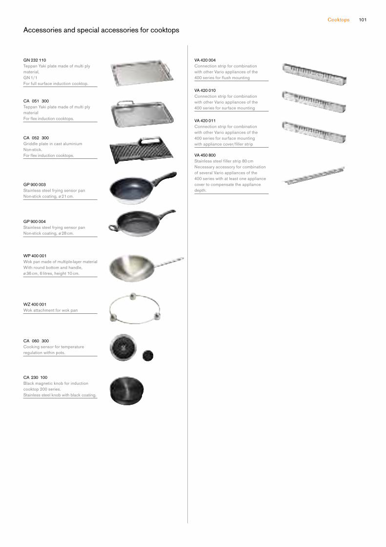
101Cooktops
Accessories and special accessories for cooktops
G N 232 110
Teppan Yaki plate made of multi ply
material,
GN1/1For full surface induction cooktop.
CA 051 300
Teppan Yaki plate made of multi ply
material
Forflexinductioncooktops.
CA 052 300
Griddle plate in cast aluminium
Non-stick.Forflexinductioncooktops.
G P 900 003
Stainless steel frying sensor pan
Non-stickcoating,ø21cm.
G P 900 004
Stainless steel frying sensor pan
Non-stickcoating,ø28cm.
W P 400 001
Wok pan made of multiple-layer material
With round bottom and handle,
ø 36 cm, 6 litres, height 10 cm.
W Z 400 001
Wok attachment for wok pan
CA 060 300
Cooking sensor for temperature
regulation within pots.
CA 230 100
Black magnetic knob for induction
cooktop 200 series.
Stainless steel knob with black coating.
V A 420 004
Connection strip for combination
with other Vario appliances of the
400seriesforflushmounting
V A 420 010
Connection strip for combination
with other Vario appliances of the
400 series for surface mounting
V A 420 011
Connection strip for combination
with other Vario appliances of the
400 series for surface mounting
withappliancecover/fillerstrip
V A 450 800
Stainlesssteelfillerstrip80cmNecessaryaccessoryforcombinationof several Vario appliances of the
400 series with at least one appliance
cover to compensate the appliance
depth.

103
The ventilation appliances
Checklist for the modular ventilation appliances 400 and 200 series 104
Planning notes 105
Telescopic table ventilation 400 series 106
Recommended configurations for table ventilation 108
Vario downdraft ventilation 400 series 110
Recommended configurations for vario downdraft ventilation 400 series 114
Vario downdraft ventilations 200 series 116
Recommended configurations for vario downdraft ventilation 200 series 118
Remote fan units 120
Island hoods 200 series 124
Wall mounted hoods 200 series 126
Slide out rangehoods 200 series 128
Integrated rangehoods 200 series 130
Accessories | special accessories 132
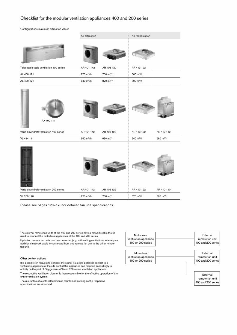
Checklist for the modular ventilation appliances 400 and 200 series
Air extraction Air recirculation
Telescopic table ventilation 400 series AR 401 142 AR 403 122 AR 413 122
AL 400 191 770 m3/h 750 m3/h 660 m3/h
AL 400 121 840 m3/h 820 m3/h 700 m3/h
Vario downdraft ventilation 400 series AR 401 142 AR 403 122 AR 413 122 AR 410 110
VL 414 111 650 m3/h 630 m3/h 640 m3/h 560 m3/h
Vario downdraft ventilation 200 series AR 401 142 AR 403 122 AR 413 122 AR 410 110
VL 200 120 720 m3/h 750 m3/h 670 m3/h 600 m3/h
The external remote fan units of the 400 and 200 series have a network cable that is used to connect the motorless appliances of the 400 and 200 series.
Up to two remote fan units can be connected (e.g. with ceiling ventilation), whereby an additional network cable is connected from one remote fan unit to the other remote fan unit.
Other control options
It is possible on request to connect the signal via a zero potential contact to a ventilation appliance at the site so that this appliance can respond accordingly to activity on the part of Gaggenau's 400 and 200 series ventilation appliances.
The respectiveventilationplanneristhenresponsiblefortheeffectiveoperationoftheentire ventilation system.
The guarantee of electrical function is maintained as long as the respective specificationsareobserved.
Configurations maximum extraction values
Please see pages 120–123 for detailed fan unit specifications.
AA 490 111
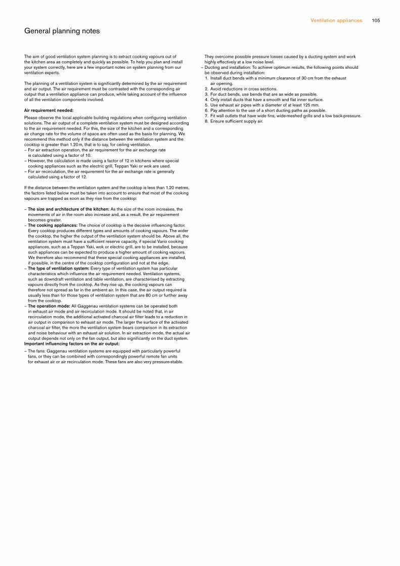
105Ventilation appliances
General planning notes
The aim of good ventilation system planning is to extract cooking vapours out of the kitchen area as completely and quickly as possible. To help you plan and install your system correctly, here are a few important notes on system planning from our ventilation experts.
Theplanningofaventilationsystemissignificantlydeterminedbytheairrequirementand air output. The air requirement must be contrasted with the corresponding air outputthataventilationappliancecanproduce,whiletakingaccountoftheinfluenceof all the ventilation components involved.
Air requirement needed:
Pleaseobservethelocalapplicablebuildingregulationswhenconfiguringventilationsolutions. The air output of a complete ventilation system must be designed according to the air requirement needed. For this, the size of the kitchen and a corresponding air change rate for the volume of space are often used as the basis for planning. We recommend this method only if the distance between the ventilation system and the cooktop is greater than 1.20 m, that is to say, for ceiling ventilation. – For air extraction operation, the air requirement for the air exchange rate
is calculated using a factor of 10.– However, the calculation is made using a factor of 12 in kitchens where special
cooking appliances such as the electric grill, Teppan Yaki or wok are used.– For air recirculation, the air requirement for the air exchange rate is generally
calculated using a factor of 12.
If the distance between the ventilation system and the cooktop is less than 1.20 metres, the factors listed below must be taken into account to ensure that most of the cooking vapours are trapped as soon as they rise from the cooktop:
– The size and architecture of the kitchen: As the size of the room increases, the movements of air in the room also increase and, as a result, the air requirement becomes greater.
– The cooking appliances: Thechoiceofcooktopisthedecisiveinfluencingfactor.Everycooktopproducesdifferenttypesandamountsofcookingvapours.Thewiderthe cooktop, the higher the output of the ventilation system should be. Above all, the ventilationsystemmusthaveasufficientreservecapacity,ifspecialVariocookingappliances, such as a Teppan Yaki, wok or electric grill, are to be installed, because such appliances can be expected to produce a higher amount of cooking vapours. We therefore also recommend that these special cooking appliances are installed, ifpossible,inthecentreofthecooktopconfigurationandnotattheedge.
– The type of ventilation system: Every type of ventilation system has particular characteristicswhichinfluencetheairrequirementneeded.Ventilationsystems,such as downdraft ventilation and table ventilation, are characterised by extracting vapours directly from the cooktop. As they rise up, the cooking vapours can therefore not spread as far in the ambient air. In this case, the air output required is usually less than for those types of ventilation system that are 80 cm or further away from the cooktop.
– The operation mode: All Gaggenau ventilation systems can be operated both in exhaust air mode and air recirculation mode. It should be noted that, in air recirculationmode,theadditionalactivatedcharcoalairfilterleadstoareductioninair output in comparison to exhaust air mode. The larger the surface of the activated charcoalairfilter,themoretheventilationsystembearscomparisoninitsextractionand noise behaviour with an exhaust air solution. In air extraction mode, the actual air outputdependsnotonlyonthefanoutput,butalsosignificantlyontheductsystem.
Important influencing factors on the air output:– The fans: Gaggenau ventilation systems are equipped with particularly powerful
fans, or they can be combined with correspondingly powerful remote fan units for exhaust air or air recirculation mode. These fans are also very pressure-stable.
They overcome possible pressure losses caused by a ducting system and work highlyeffectivelyatalownoiselevel.
– Ducting and installation: To achieve optimum results, the following points should be observed during installation:
1. Install duct bends with a minimum clearance of 30 cm from the exhaust air opening. 2. Avoid reductions in cross sections. 3. For duct bends, use bends that are as wide as possible. 4. Only installductsthathaveasmoothandflatinnersurface. 5. Use exhaust air pipes with a diameter of at least 125 mm. 6. Pay attention to the use of a short ducting paths as possible. 7. Fit walloutletsthathavewidefins,wide-meshedgrillsandalowback-pressure. 8. Ensure sufficientsupplyair.

A L 400 121
Stainless steel
Width 120 cm
Air extraction / Air recirculation
Motorless
A L 400 191
Stainless steel
Width 90 cm
Air extraction / Air recirculation
Motorless
NecessaryinstallationaccessoriesA D 754 045
Connectionpiecefor2aluflexpipesDN150roundFitting AL 400, front or back side.
A D 854 043
Connectingpiecefor2flatductsDN150Fitting AL 400, bottom side.
A D 854 045
Connectingpiecefor2flatductsDN150Fitting AL 400, front or back side.
Installation accessories
A A 010 410
Air exhaust grill air recirculation
Stainless steel-coloured, 90 cm,
includinginstallationfittings,heightadjustable.
A A 409 401
Furniture support for table ventilation
AL 400 90 cm
Can be combined with table ventilation
AL 400.
Recommended as bearer for the
worktop, instead of a cabinet frame.
A A 409 431
Furniture support for table ventilation
AL 400 120 cm
Can be combined with table ventilation
AL 400.
Recommended as bearer for the
worktop, instead of a cabinet frame.
A D 704 048
AircollectorboxDN150roundpipe2xDN150roundductairintake.For connecting 1 x AL 400 to
AR 403/AR 413
A D 704 049
AircollectorboxDN150flatduct2xDN150flatductairintake.To connect 1 x AL 400 to remote fan
AR 403/AR 413 bottom side.
Installation accessories for the air recirculation ducts you will find on pages 132–141.
Table ventilation 400 series
A L 400
— Extendable table ventilation, when
not in use can be completely
lowered into the worktop
— Can be combined perfectly with
other Vario appliances of the
400 series
— Dimmable, neutral white surface
LED light for ideal illumination of
the whole cooktop
— Precision crafted 3 mm
stainless steel
— For surface mounting with a visible
edgeorforflushmounting — Motorless, can be combined with
Gaggenau BLDC remote fan units
Output
Power levels depend on the remote fan
unit, see page 104.
Features
3 electronically controlled power levels
and 1 intensive mode.
Interval ventilation, 6 min.
Run-on function, 6 min.
Greasefiltersaturationindicator.Cartridge-typefilter,dishwasher-safe.NeutralwhitesurfaceLEDlight (3600 K), continuously dimmable.
Lamp output 4 x 5 W.
Illuminance 191 lx.
Spare covers for closing air outlets.
Noconnectingpieceincluded.
Consumption data
Consumption data is referred to a
configurationAL400121/AL400191with the remote fan unit AR 401 142.
Energy consumption
42.6/45.5 kWh/year.
Sound level min. 44/45 dB /
max. 59/61 dB normal mode.
Planning notes
Refer to the table on page 104 for
the matching remote fan units for air
recirculation or air extraction mode.
Secure the control unit to the side
panel of the cabinet, not to the base of
thecabinetorthekitchenfloor.Connection to the respective
appliances via network cable.
AL 400 121 (AL 400 191)
For operation with 4 (3) Vario 200
series
cooktops, 3 (2) Vario 400 series
cooktopsoracooktopconfigurationof up to 120 cm (92 cm) wide.
Operation of Vario cooking appliances
only possible without appliance cover.
Max. output of cooktops 18 kW.
Installation is possible in worktops
made of stone, synthetics or solid
wood. Heat resistance and watertight
sealing of the cut edges must
be observed. Concerning other
materials please consult the worktop
manufacturer.
The remaining surface of the worktop
(min. 50 mm) between the cut-outs
must be reinforced with a support. It is
recommended to use furniture support
AA 409 401/431.
Ovens that do not exceed the maximum
allowed cabinet temperature can be
combined with the table ventilation if
built-in situation permits.
To avoid smoke when frying/grilling
refer to the manuals of VR/VP.
When installing a ventilation hood with
air extraction mode and a chimney-
ventedfireplace,thepowersupplylineof the ventilation appliance needs a
suitable safety switch.
Please read additional planning notes
on page 108–109.
Connection
Total connected load 65 W
Connecting cable 1.7 m, with plug.
Networkcable1.2m.

107Ventilation appliances
AL 400 cut-out for surface mounting

Recommended configurations for table ventilations 400 series and remote fan units
Planning example 1
1 x AL 400 with AR 403 122 (air extraction) / AR 413 122 (air recirculation)
Connectiontothefrontwithflatductoraluflexpipe,DN150;cabinetinstallation
Combination
1 x AL 400 table ventilation combined with 1 x AR 403 122 / AR 413 122 remote fan unit
Good to know
– The air collector box can be screwed directly to the remote fan unit. The reducing
piece supplied is not needed in this case.
–Foroptimumperformance,therecirculatedairrequiressufficientspacetoescape(outflowsurfaceareaofatleast440cm²foreachremotefanunit).
List of accessories 2
– 1 x AD 754 045 (connecting pieces for roundduct,2xDN150)– 2 xAD751010(aluflexpiperound,DN150)– 1 x AD 704 048 (air collector box for AL 400)
List of accessories 1
–1xAD754045(connectionpiecesforroundduct,2xDN150)– 2 x AD 857 042 (Flat duct adapter round 90°)
–1xAD704049(AircollectorboxDN150flatduct)–1xAD853011(Flatductsystemflexpipe)– 1 x AD 990 090 (adhesive tape for bonding the ducts)
Good to know – for correct planning and installation
– The ducting can essentially be connected to the front, rear or below with the AL 400 table ventilation. The respective connecting pieces are available for this purpose.
– Plastic ducts can be used for installation behind a gas appliance. The maximum permitted performance of the cooktops is 18 kW.
– If the AL 400 121 is installed in air recirculation mode and intensive cooking (e.g. Vario Teppan Yaki) is involved, we recommend to use a second remote fan unit AR 413 122
to support the vapour catch behaviour, see planning example 6.
– Vario cooktops with intensive vapour formation like Vario Teppan Yaki or Vario electric grill should be placed central in front of the ventilation appliance;
in case of Vario electric grill air recirculation is not recommended.
–Securethecontrolunittothesidepanelofthecabinet,nottothebaseofthecabinetorthekitchenfloor.
Planning example 2
1 x AL 400 with AR 403 122 (air extraction) / AR 413 122 (air recirculation)
Connectiondownwardwithflexduct,DN150,cabinetinstallation
Combination
1 AL 400 table ventilation combined with 1 x AR 403 122 / AR 413 122 remote fan unit
Good to know
– The air collector box can be screwed directly on the remote fan unit. The reducing
piece supplied is not needed in this case.
–Foroptimumperformance,therecirculatedairrequiressufficientspacetoescape(outflowsurfaceareaofatleast440cm²foreachremotefanunit).
List of accessories 1
–1xAD854043(connectingpiecesforflatductdownward,2xDN150)– 1 x AD 704 049 (air collector box for AL 400)
–1xAD853011(FlatductFlexduct,DN150)– 1 x AD 990 090 (Adhesive tape for bonding the ducts)
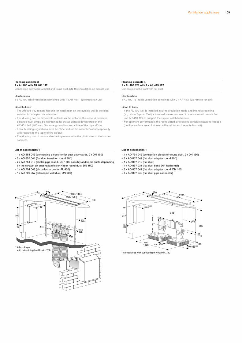
109Ventilation appliances
Planning example 3
1 x AL 400 with AR 401 142
Connectiondownwardwithflatandroundduct,DN150;installationonoutsidewall
Combination
1 x AL 400 table ventilation combined with 1 x AR 401 142 remote fan unit
Good to know
– The AR 401 142 remote fan unit for installation on the outside wall is the ideal
solution for compact air extraction.
– The ducting can be directed to outside via the cellar in this case. A minimum
distance must simply be maintained for the air exhaust downwards on the
AR 401 142 (100 cm). Distance ground to central line of the pipe: 60 cm.
– Local building regulations must be observed for the cellar breakout (especially
withrespecttothetopicoffiresafety).– The ducting can of course also be implemented in the plinth area of the kitchen
cabinets.
Planning example 4
1 x AL 400 121 with 2 x AR 413 122
Connectiontothefrontwithflatduct
Combination
1 AL 400 121 table ventilation combined with 2 x AR 413 122 remote fan unit
Good to know
– If the AL 400 121 is installed in air recirculation mode and intensive cooking
(e.g. Vario Teppan Yaki) is involved, we recommend to use a second remote fan
unit AR 413 122 to support the vapour catch behaviour
–Foroptimumperformance,therecirculatedairrequiressufficientspacetoescape(outflowsurfaceareaofatleast440cm²foreachremotefanunit).
List of accessories 1
–1xAD854043(connectingpiecesforflatductdownwards,2xDN150)–2xAD857041(flatducttransitionround90°)–2xAD751010(aluflexpiperound,DN150);possiblyadditionalductsdependingontheexhaustairducting(aluflexorNaberroundduct,DN150)
– 1 x AD 704 048 (air collector box for AL 400)
–1xAD702052(telescopicwallduct,DN200)
List of accessories 1
–1xAD754045(connectionpiecesforroundduct,2xDN150)–2xAD857042(flatductadapterround90°)–1xAD857010(flatduct)–1xAD857031(flatductbend90°horizontal)–2xAD857041(flatductadapterround,DN150)–4xAD857040(flatductpipeconnector)

V L 414 111
Stainless steel
Width 11 cm
Air extraction / Air recirculation
Without motor and control knob
NecessaryinstallationaccessoriesA A 490 111
Stainless steel control knob
A D 724 042
Connection piece for round pipe
DN150ForVL414For installation to left or right side of
VL additional adapter AD 724 041 is
necessary.
A D 724 041
Round duct connection additional
adapter for VL 414 on the side
Metal zinc coated
Necessaryforinstallationtoleftorright side of VL.
A D 854 046
FlatductsystemwithguidancefinsConnecting piece VL 414 for
DN150flat
Installation accessories
V A 420 004
Connection strip for combination
with other Vario appliances of the
400seriesforflushmountingV A 420 010
Connection strip for combination
with other Vario appliances of the
400 series for surface mounting
V A 420 011
Connection strip for combination
with other Vario appliances of the
400 series for surface mounting
withappliancecover/fillerstripV A 450 110
Stainlesssteelfillerstrip11cmNecessaryaccessoryforcombinationof several Vario appliances of the
400 series with at least one appliance
cover to compensate the appliance
depth.
Special accessories
A A 414 010
Ventilation moulding for VL 414 next to
gas appliance.
Installation accessories for the air recirculation ducts you will find on pages 132–141.
Vario downdraft ventilation 400 series
V L 414
— Highlyefficientventilationsystem at the cooktop
— Flexible power distribution, precise
extraction of cooking vapours only
at the open ventilation elements
— Can be combined perfectly with
other Vario appliances of the
400 series
— Precision crafted 3 mm
stainless steel
— For surface mounting with a visible
edgeorforflushmounting — Motorless, can be combined with
Gaggenau BLDC remote fan units
Output
Power levels depend on the remote fan
unit, see page 104.
Features
Manual opening of the ventilation
element.
Closing element made of stainless
steel, dishwasher-safe.
Metalgreasefilter,dishwasher-safe.Noconnectingpieceincluded.
Consumption data
Consumption data is referred to a
configurationwiththeremotefanunitAR 403 122.
Energy consumption 53.2 kWh/year.
Sound level min. 56 dB / max. 68 dB
normal mode.
Planning notes
Refer to the table on page 104 for
the matching remote fan units for air
recirculation or air extraction mode.
Secure the control unit to the side
panel of the cabinet, not to the base of
thecabinetorthekitchenfloor.For each VL one remote fan unit is
recommended.
Maximum cooktop width between two
VL: 60 cm.
Appliance can be snapped into the
worktopfromabove.Additionalfixingby clamps accessible from bottom up,
clamping range 30-50 mm.
If installing with the appliance cover
VA440orfillerstripVA450takeintoaccount the additional space required
for the depth.
If combining several appliances with
atleastoneappliancecover,thefillerstrip VA 450 is required to compensate
for the depth of the appliance without
the appliance cover.
If combining several Vario appliances
of the 400 series, a connection strip
VA 420 must be placed between the
appliances. Depending on the type
of installation, the corresponding
connection strip must be provided.
In the cut-out, the installation system
requires the side edge to be at least
10 mm for surface mounting and at
least13mmforflushmounting.Ensurea continuous cut surface of 90°.
The bearing capacity and stability, in
the case of thin worktops in particular,
must be supported using suitable
substructures.
Take into account the appliance weight
and additional loads.
Additionalinstructionsforflushmounting:
Installation is possible in worktops
made of stone, synthetics or solid
wood. Heat resistance and watertight
sealing of the cut edges must
be observed. Concerning other
materials please consult the worktop
manufacturer.
The groove must be continuous and
even, so that uniform placing of the
appliance on the gasket is ensured.
Do not use discontinuous lining.
The joint width may vary due to size
tolerances of the combinations and of
the worktop cut-out.
If installing several appliances in
individual cut-outs allow for a division
bar of minimum 50 mm between the
individual cut-outs.
If operated next to gas appliances,
the ventilation moulding AA 414 010
is recommended to ensure maximum
performance of the cooktop.
Ifinstallednexttogasappliances,flatducts must not be used for the piping
up to the fan unit.
IfinstallednexttoVP414,theflatductmust not be positioned underneath the
VP 414.
Please read the installation details
regarding air ducting on page 114–115.
Please read additional planning notes
on page 72–77.
Connection
Connection cable 2.0 m between
ventilation element VL 414 and control
knob AA 490.

111Ventilation appliances
AD 854 046
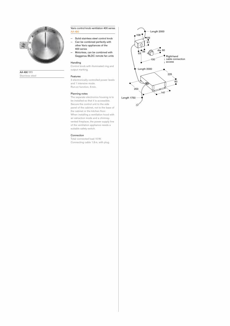
A A 490 111
Stainless steel
Vario control knob ventilation 400 series
A A 490
— Solid stainless steel control knob
— Can be combined perfectly with
other Vario appliances of the
400 series
— Motorless, can be combined with
Gaggenau BLDC remote fan units
Handling
Control knob with illuminated ring and
output marking.
Features
3 electronically controlled power levels
and 1 intensive mode.
Run-on function, 6 min.
Planning notes
The separate electronics housing is to
be installed so that it is accessible.
Secure the control unit to the side
panel of the cabinet, not to the base of
thecabinetorthekitchenfloor.When installing a ventilation hood with
air extraction mode and a chimney-
ventedfireplace,thepowersupplylineof the ventilation appliance needs a
suitable safety switch.
Connection
Total connected load 10 W.
Connecting cable 1.8 m, with plug.

113Ventilation appliances
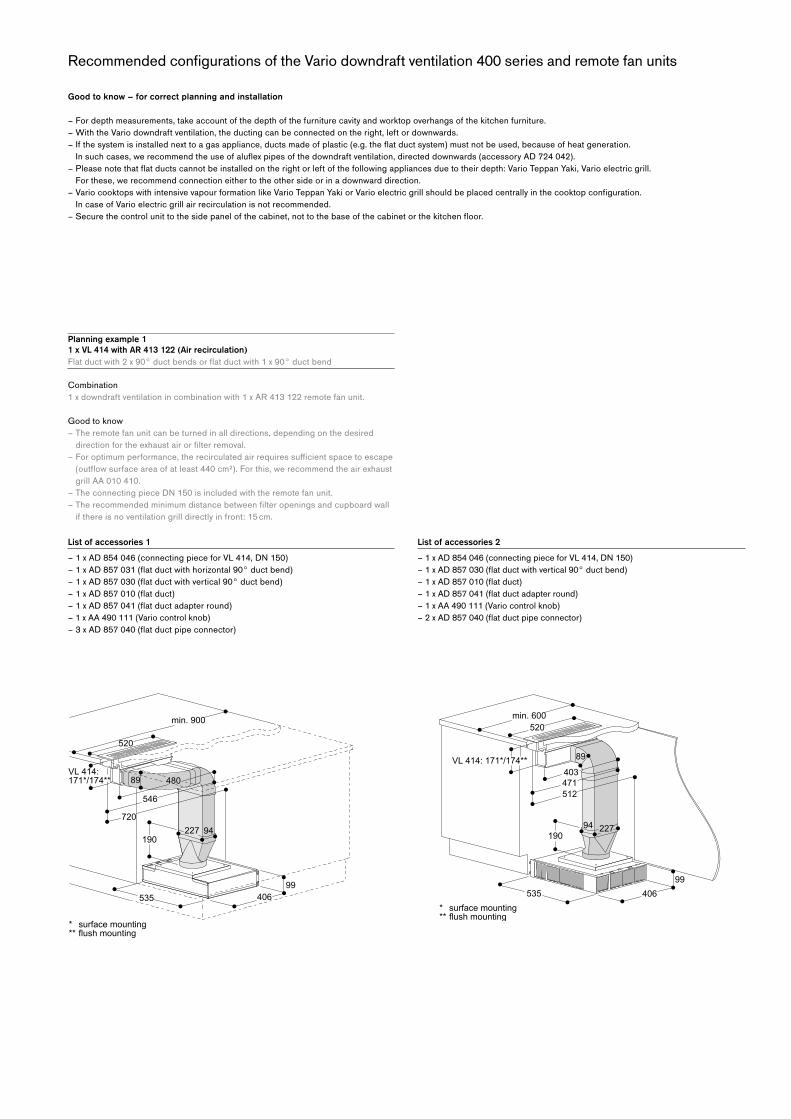
Recommended configurations of the Vario downdraft ventilation 400 series and remote fan units
Planning example 1
1 x VL 414 with AR 413 122 (Air recirculation)
Flatductwith2x90°ductbendsorflatductwith1x90°ductbend
Combination
1 x downdraft ventilation in combination with 1 x AR 413 122 remote fan unit.
Good to know
– The remote fan unit can be turned in all directions, depending on the desired
directionfortheexhaustairorfilterremoval.–Foroptimumperformance,therecirculatedairrequiressufficientspacetoescape(outflowsurfaceareaofatleast440cm²).Forthis,werecommendtheairexhaustgrill AA 010 410.
–TheconnectingpieceDN150isincludedwiththeremotefanunit.–Therecommendedminimumdistancebetweenfilteropeningsandcupboardwall
if there is no ventilation grill directly in front: 15 cm.
List of accessories 1–1xAD854046(connectingpieceforVL414,DN150)–1xAD857031(flatductwithhorizontal90°ductbend)–1xAD857030(flatductwithvertical90°ductbend)–1xAD857010(flatduct)–1xAD857041(flatductadapterround)– 1 x AA 490 111 (Vario control knob)
–3xAD857040(flatductpipeconnector)
List of accessories 2– 1xAD854046(connectingpieceforVL414,DN150)– 1xAD857030(flatductwithvertical90°duct bend)
– 1xAD857010(flatduct)– 1xAD857041(flatductadapterround)– 1 x AA 490 111 (Vario control knob)
–2xAD857040(flatductpipeconnector)
Good to know – for correct planning and installation
– For depth measurements, take account of the depth of the furniture cavity and worktop overhangs of the kitchen furniture.
– With the Vario downdraft ventilation, the ducting can be connected on the right, left or downwards.
– If thesystemisinstallednexttoagasappliance,ductsmadeofplastic(e.g.theflatductsystem)mustnotbeused,becauseofheatgeneration. Insuchcases,werecommendtheuseofaluflexpipesofthedowndraftventilation,directeddownwards(accessoryAD724042).
– Please notethatflatductscannotbeinstalledontherightorleftofthefollowingappliancesduetotheirdepth:VarioTeppanYaki,Varioelectricgrill. For these, we recommend connection either to the other side or in a downward direction.
– Vario cooktopswithintensivevapourformationlikeVarioTeppanYakiorVarioelectricgrillshouldbeplacedcentrallyinthecooktopconfiguration. In case of Vario electric grill air recirculation is not recommended.
–Securethecontrolunittothesidepanelofthecabinet,nottothebaseofthecabinetorthekitchenfloor.

115Ventilation appliances
Planning example 2
1 x VL 414 with AR 403 122 (Air extraction)
Flatductwith2x90°ductbendsorflatductwith1x90°ductbend
Combination
1 x downdraft ventilation in combination with 1 x AR 403 122 remote fan unit
Good to know
TheconnectingpieceDN150isincludedwiththeremotefanunit.
List of accessories 2– 1xAD854046(connectingpieceforVL414,DN150)– 1xAD857030(flatductwithvertical90°duct bend)
– 1xAD857010(flatduct)– 1xAD857041(flatductadapterround)– 1 x AA 490 111 (Vario control knob)
– 2xAD857040(flatductpipeconnector)
List of accessories 1–1xAD854046(connectingpieceforVL414,DN150)–1xAD857031(flatductwithhorizontal90°ductbend)–1xAD857030(flatductwithvertical90°ductbend)–1xAD857010(flatduct)–1xAD857041(flatductadapterround)– 1 x AA 490 111 (Vario control knob)
–3xAD857040(flatductpipeconnector)
Planning example 3
1 x VL with AR 410 110 (Air recirculation)
Flat duct with 2 x 90° bends
Combination
1 x downdraft ventilation in combination with 1 x AR 410 110 remote fan unit
Good to know
Thecharcoalfilterexchangeispossiblefrombothsides.Allowaccessibilitytothecharcoalfiltersinthelowercabinetforreplacingthefilter.Itispossibletopositiontheremotefanunitdirectonthefloororfixitwiththeretaining brackets with a cut-out in the furniture base.
Forconfiguration2isdependingonthedepthoftheislandasecondflatduct AD 852 010 needed.
Foroptimumperformance,therecirculatedairrequiressufficientspacetoescape(outflowsurfaceareaofatleast440cm²).List of accessories 1–1xAD854046(connectingpieceforVL414,DN150)–1xAD857031(flatductwithhorizontal90°ductbend)–1xAD857030(flatductwithvertical90°ductbend)–1xAD857010(flatduct)–2xAD857040(flatductpipeconnector)– 1 x AA 490 111 (Vario control knob)
List of accessories 2– 1 xAD854046(connectingpieceforVL414,DN150)– 1 xAD857031(flatductwithhorizontal90°ductbend)– 1 xAD857030(flatductwithvertical90°ductbend)– 1 x AD857010(flatduct)–3xAD857040(flatductpipeconnector)– 1 x AA 490 111 (Vario control knob)
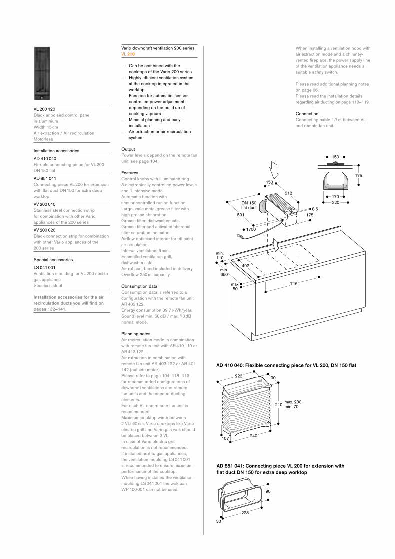
V L 200 120
Black anodised control panel
in aluminium
Width 15 cm
Air extraction / Air recirculation
Motorless
Installation accessories
A D 410 040
Flexible connecting piece for VL 200
DN150flatA D 851 041
Connecting piece VL 200 for extension
withflatductDN150forextradeepworktop
V V 200 010
Stainless steel connection strip
for combination with other Vario
appliances of the 200 series
V V 200 020
Black connection strip for combination
with other Vario appliances of the
200 series
Special accessories
L S 041 001
Ventilation moulding for VL 200 next to
gas appliance
Stainless steel
Installation accessories for the air recirculation ducts you will find on pages 132–141.
Vario downdraft ventilation 200 series
V L 200
— Can be combined with the
cooktops of the Vario 200 series
— Highlyefficientventilationsystem at the cooktop integrated in the
worktop
— Function for automatic, sensor-
controlled power adjustment
depending on the build-up of
cooking vapours
— Minimal planning and easy
installation
— Air extraction or air recirculation
system
Output
Power levels depend on the remote fan
unit, see page 104.
Features
Control knobs with illuminated ring.
3 electronically controlled power levels
and 1 intensive mode.
Automatic function with
sensor-controlled run-on function.
Large-scalemetalgreasefilterwithhigh grease absorption.
Greasefilter,dishwasher-safe.Greasefilterandactivatedcharcoalfiltersaturationindicator.Airflow-optimisedinteriorforefficientair circulation.
Interval ventilation, 6 min.
Enamelled ventilation grill,
dishwasher-safe.
Air exhaust bend included in delivery.
Overflow250mlcapacity.
Consumption data
Consumption data is referred to a
configurationwiththeremotefanunitAR 403 122.
Energy consumption 39.7 kWh/year.
Sound level min. 58 dB / max. 73 dB
normal mode.
Planning notes
Air recirculation mode in combination
with remote fan unit with AR 410 110 or
AR 413 122.
Air extraction in combination with
remote fan unit AR 403 122 or AR 401
142 (outside motor).
Please refer to page 104, 118–119
forrecommendedconfigurationsofdowndraft ventilations and remote
fan units and the needed ducting
elements.
For each VL one remote fan unit is
recommended.
Maximum cooktop width between
2 VL: 60 cm. Vario cooktops like Vario
electric grill and Vario gas wok should
be placed between 2 VL.
In case of Vario electric grill
recirculation is not recommended.
If installed next to gas appliances,
the ventilation moulding LS 041 001
is recommended to ensure maximum
performance of the cooktop.
When having installed the ventilation
moulding LS 041 001 the wok pan
WP 400 001 can not be used.
When installing a ventilation hood with
air extraction mode and a chimney-
ventedfireplace,thepowersupplylineof the ventilation appliance needs a
suitable safety switch.
Please read additional planning notes
on page 86.
Please read the installation details
regarding air ducting on page 118–119.
Connection
Connecting cable 1.7 m between VL
and remote fan unit.
AD 410 040: Flexible connecting piece for VL 200, DN 150 flat
AD 851 041: Connecting piece VL 200 for extension with
flat duct DN 150 for extra deep worktop

117Ventilation appliances
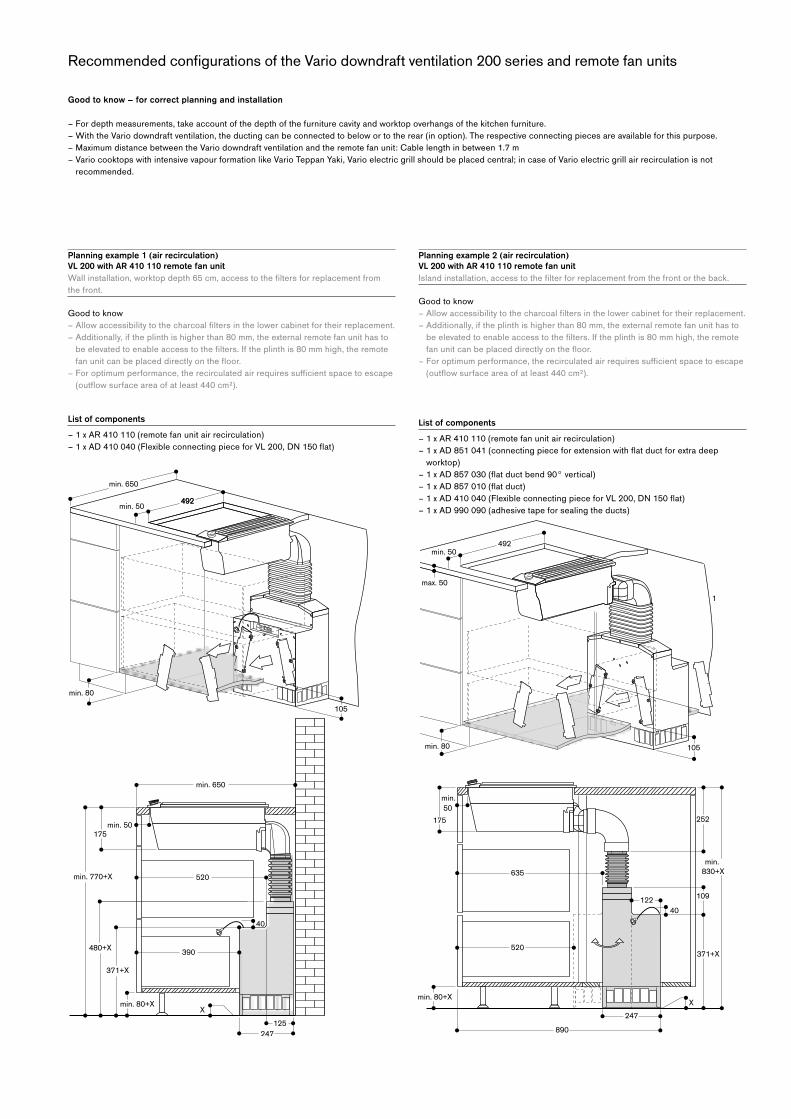
Good to know – for correct planning and installation
– For depth measurements, take account of the depth of the furniture cavity and worktop overhangs of the kitchen furniture.
– With the Vario downdraft ventilation, the ducting can be connected to below or to the rear (in option). The respective connecting pieces are available for this purpose.
– Maximum distance between the Vario downdraft ventilation and the remote fan unit: Cable length in between 1.7 m
– Vario cooktops with intensive vapour formation like Vario Teppan Yaki, Vario electric grill should be placed central; in case of Vario electric grill air recirculation is not
recommended.
Recommended configurations of the Vario downdraft ventilation 200 series and remote fan units
Planning example 1 (air recirculation)
VL 200 with AR 410 110 remote fan unitWallinstallation,worktopdepth65cm,accesstothefiltersforreplacementfromthe front.
Good to know
–Allowaccessibilitytothecharcoalfiltersinthelowercabinetfortheirreplacement.– Additionally, if the plinth is higher than 80 mm, the external remote fan unit has to
beelevatedtoenableaccesstothefilters.Iftheplinthis80mmhigh,theremotefanunitcanbeplaceddirectlyonthefloor.
–Foroptimumperformance,therecirculatedairrequiressufficientspacetoescape(outflowsurfaceareaofatleast440cm²).
List of components – 1 x AR 410 110 (remote fan unit air recirculation)
–1xAD410040(FlexibleconnectingpieceforVL200,DN150flat)
Planning example 2 (air recirculation)
VL 200 with AR 410 110 remote fan unitIslandinstallation,accesstothefilterforreplacementfromthefrontortheback.
Good to know
–Allowaccessibilitytothecharcoalfiltersinthelowercabinetfortheirreplacement.– Additionally, if the plinth is higher than 80 mm, the external remote fan unit has to
beelevatedtoenableaccesstothefilters.Iftheplinthis80mmhigh,theremotefanunitcanbeplaceddirectlyonthefloor.
–Foroptimumperformance,therecirculatedairrequiressufficientspacetoescape(outflowsurfaceareaofatleast440cm²).
List of components – 1 x AR 410 110 (remote fan unit air recirculation)
–1xAD851041(connectingpieceforextensionwithflatductforextradeepworktop)
–1xAD857030(flatductbend90°vertical)–1xAD857010(flatduct)–1xAD410040(FlexibleconnectingpieceforVL200,DN150flat)– 1 x AD 990 090 (adhesive tape for sealing the ducts)
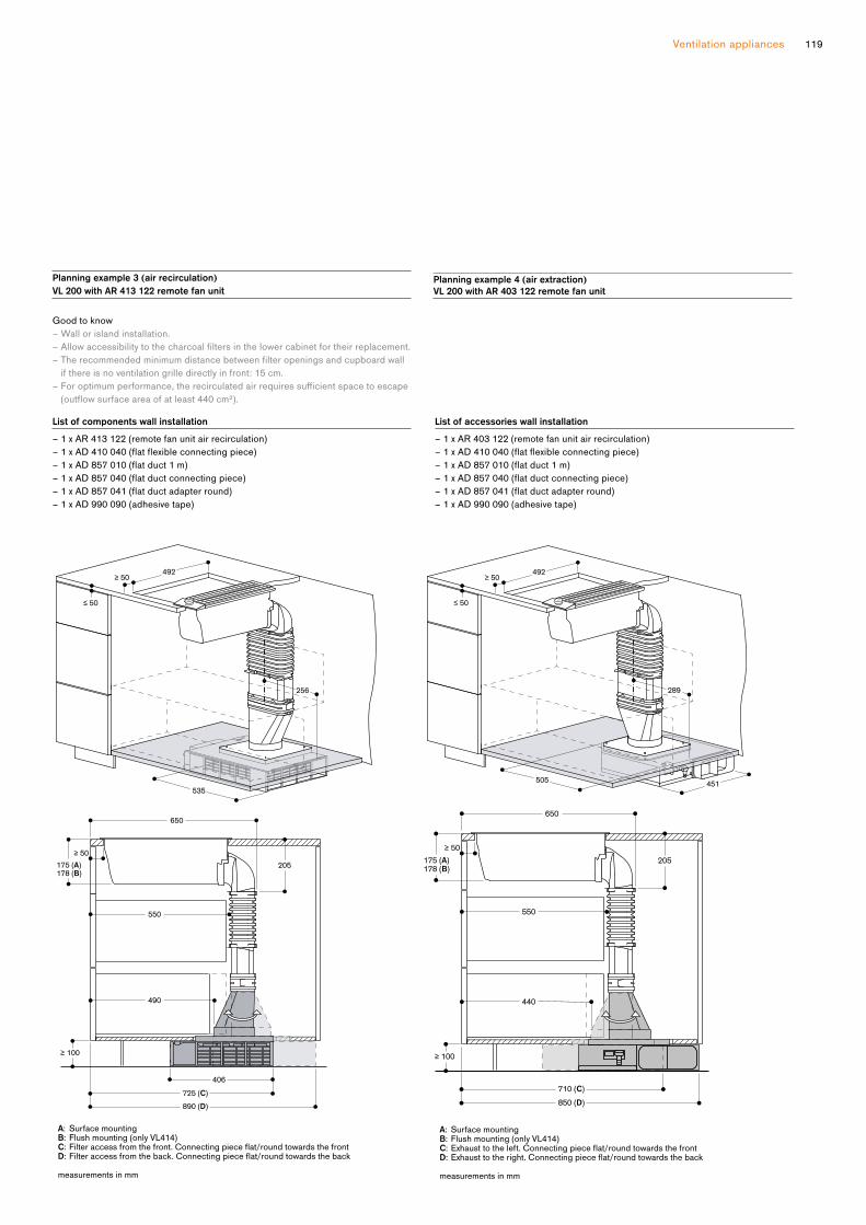
119Ventilation appliances
Planning example 4 (air extraction)
VL 200 with AR 403 122 remote fan unit
List of accessories wall installation– 1 x AR 403 122 (remote fan unit air recirculation)
–1xAD410040(flatflexibleconnectingpiece)–1xAD857010(flatduct1m)–1xAD857040(flatductconnectingpiece)–1xAD857041(flatductadapterround)– 1 x AD 990 090 (adhesive tape)
Planning example 3 (air recirculation)
VL 200 with AR 413 122 remote fan unit
Good to know
– Wall or island installation.
–Allowaccessibilitytothecharcoalfiltersinthelowercabinetfortheirreplacement.–Therecommendedminimumdistancebetweenfilteropeningsandcupboardwall
if there is no ventilation grille directly in front: 15 cm.
–Foroptimumperformance,therecirculatedairrequiressufficientspacetoescape(outflowsurfaceareaofatleast440cm²).
List of components wall installation– 1 x AR 413 122 (remote fan unit air recirculation)
–1xAD410040(flatflexibleconnectingpiece)–1xAD857010(flatduct1m)–1xAD857040(flatductconnectingpiece)–1xAD857041(flatductadapterround)– 1 x AD 990 090 (adhesive tape)
256
535
492≥50≥50
≤50
≥100
175 (178 (
550
490
650
205
406
725 ( C )
890 ( D )
≥50≥50
≤50
≥100
175 ( A ) 178 ( B )
A: Surface mountingB: Flush mounting (only VL414)C: Filter access from the front. Connecting piece flat/round towards the front D: Filter access from the back. Connecting piece flat/round towards the back
measurements in mm
≥50≥50
≤50
≥100
550
440
650
205
710 ( C ) 850 ( D )
≥ 50
≥ 100
175 ( A ) 178 ( B )
492≥50
≤50
289
451505
A: Surface mountingB: Flush mounting (only VL414)C: Exhaust to the left. Connecting piece flat/round towards the front D: Exhaust to the right. Connecting piece flat/round towards the back
measurements in mm
≥50
≤50
451505
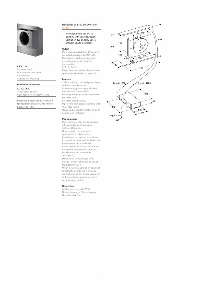
A R 401 142
Stainless steel
Max. air output 910 m³/h
Air extraction
Outside wall mounting
Installation accessories
A D 702 052
Telescopic wall-duct
ConnectionpieceDN200round
Installation accessories for the air recirculation ducts you will find on pages 132–141.
Remote fan unit 400 and 200 series
A R 401
— Powerful remote fan unit to
combine with Vario downdraft
ventilation 400 and 200 series
— EfficientBLDCtechnology
Output
Performance output level 3/Intensive:
AiroutputaccordingtoEN61591. Sound power and sound pressure
depending on built-in situation.
Air extraction:
720 / 910 m³/h.
Power levels depend on the motorless
appliances, see table on page 104.
Features
3 electronically controlled power levels
and one intensive mode.
Fantechnologywithhighlyefficient,brushless DC motor (BLDC).
Including sound insulation to minimise
the noise level.
Stainless steel housing.
Pipe connection pieces on intake side:
1xDN200round.Retaining bracket for installation on an
outside wall enclosed.
Planning notes
Powerful remote fan unit to combine
with Vario downdraft ventilation
400 and 200 series.
Connection to the respective
appliances via network cable.
Installation in an exterior area allows
for a reduced noise level in the kitchen
Installation on an outside wall.
Control box must be installed indoors.
Acceptable temperature range for
installation of the control box:
-25 to 60 °C.
Distance for free air space from
ground (or other object) to centre of
the pipe: min 60 cm
When installing a ventilation hood with
air extraction mode and a chimney-
ventedfireplace,thepowersupplylineof the ventilation appliance needs a
suitable safety switch.
Connection
Total connected load 180 W.
Connecting cable 1.8 m, with plug.
Networkcable5m.

121Ventilation appliances
A R 410 110
Metal housing
Max. air output 660 m³/h
Air recirculation
Installation in the cupboard
Installation accessories for the air recirculation ducts you will find on pages 132–141.
Remote fan unit 400 and 200 series
A R 410
— Powerful remote fan unit to
combine with Vario downdraft
ventilation 400 and 200 series
— EfficientBLDCtechnology — Particularly quiet due to patented
noise insulation
— Compact, space-saving installation
Output
Performance output level 3/Intensive:
AiroutputaccordingtoEN61591. Sound power and sound pressure
depending on built-in situation.
Air recirculation:
575 / 665 m³/h.
Power levels depend on the motorless
appliances, see table on page 104.
Features
3 electronically controlled power levels
and 1 intensive mode.
Fantechnologywithhighlyefficient,brushless DC motor (BLDC).
Including sound insulation to minimise
the noise level.
Steel housing, zinc-plated.
Pipe connection piece on intake side:
1xDN150flatduct.Retaining bracket for installation at the
furniture base enclosed.
2activatedcharcoalfiltersenclosed ex factory.
Planning notes
Powerful remote fan unit to combine
with Vario downdraft ventilation
400 and 200 series.
Connection to the respective
appliances via network cable.
Installation in a cupboard possible
with a cut-out in the furniture base or
behind the cupboard positioned on
thefloor.Filter replacement interval: 1 year
depending on cooking frequency.
Toreplacethefiltertheremotefanunitmust be accessible.
Thecharcoalfilterexchangeispossible from both sides.
Connection
Total connected load 170 W.
Connecting cable 1.8 m, with plug.
Networkcable5m.
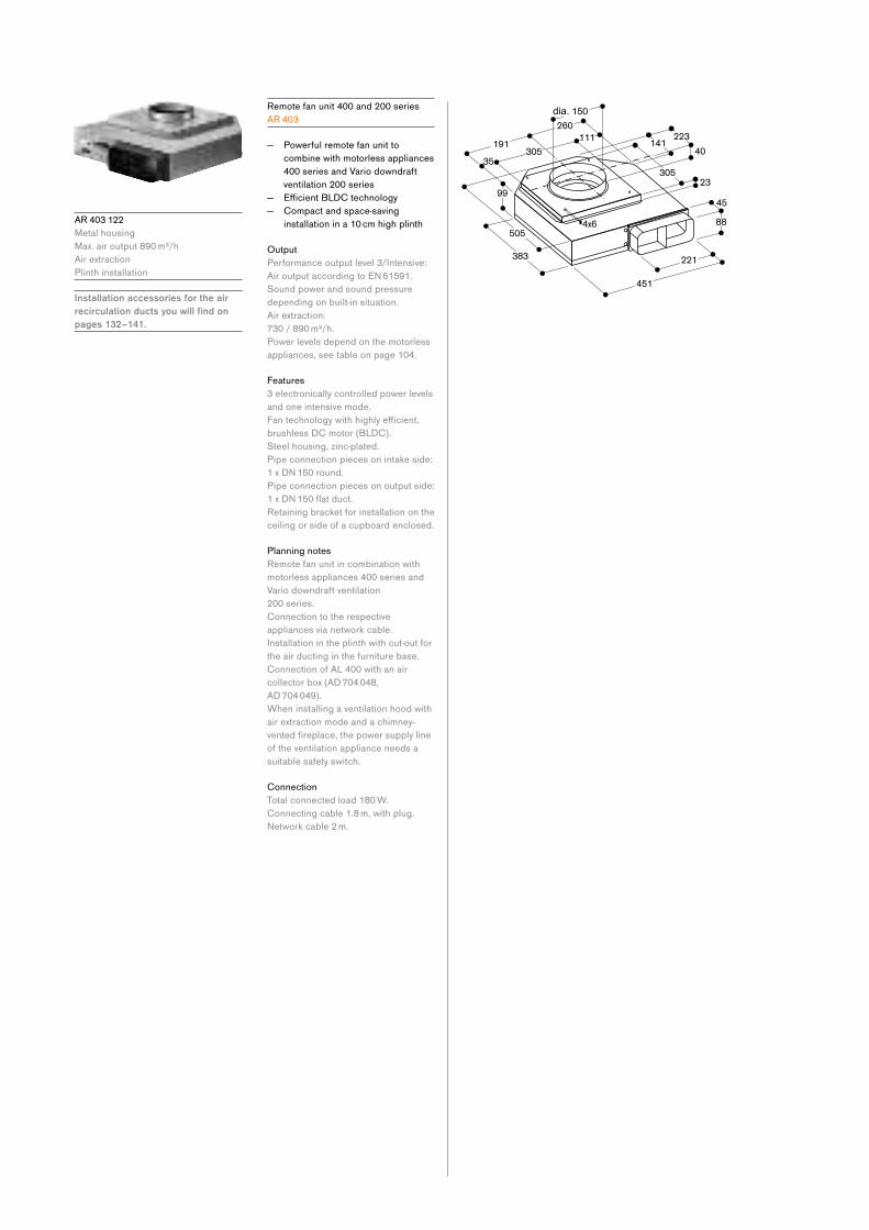
A R 403 122
Metal housing
Max. air output 890 m³/h
Air extraction
Plinth installation
Installation accessories for the air recirculation ducts you will find on pages 132–141.
Remote fan unit 400 and 200 series
A R 403
— Powerful remote fan unit to
combine with motorless appliances
400 series and Vario downdraft
ventilation 200 series
— EfficientBLDCtechnology — Compact and space-saving
installation in a 10 cm high plinth
Output
Performance output level 3/Intensive:
AiroutputaccordingtoEN61591. Sound power and sound pressure
depending on built-in situation.
Air extraction:
730 / 890 m³/h.
Power levels depend on the motorless
appliances, see table on page 104.
Features
3 electronically controlled power levels
and one intensive mode.
Fantechnologywithhighlyefficient,brushless DC motor (BLDC).
Steel housing, zinc-plated.
Pipe connection pieces on intake side:
1xDN150round.Pipe connection pieces on output side:
1xDN150flatduct.Retaining bracket for installation on the
ceiling or side of a cupboard enclosed.
Planning notes
Remote fan unit in combination with
motorless appliances 400 series and
Vario downdraft ventilation
200 series.
Connection to the respective
appliances via network cable.
Installation in the plinth with cut-out for
the air ducting in the furniture base.
Connection of AL 400 with an air
collector box (AD 704 048,
AD 704 049).
When installing a ventilation hood with
air extraction mode and a chimney-
ventedfireplace,thepowersupplylineof the ventilation appliance needs a
suitable safety switch.
Connection
Total connected load 180 W.
Connecting cable 1.8 m, with plug.
Networkcable2m.
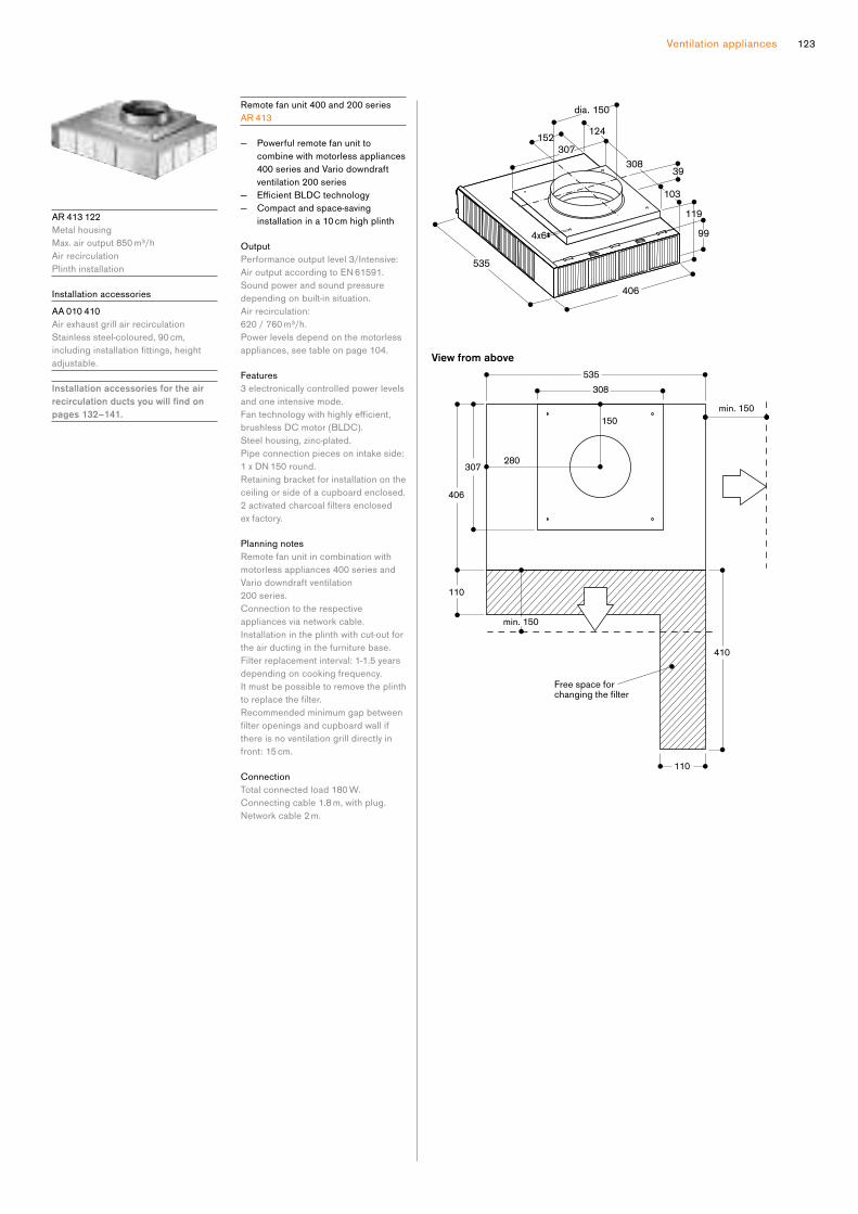
123Ventilation appliances
A R 413 122
Metal housing
Max. air output 850 m³/h
Air recirculation
Plinth installation
Installation accessories
A A 010 410
Air exhaust grill air recirculation
Stainless steel-coloured, 90 cm,
includinginstallationfittings,heightadjustable.
Installation accessories for the air recirculation ducts you will find on pages 132–141.
Remote fan unit 400 and 200 series
A R 413
— Powerful remote fan unit to
combine with motorless appliances
400 series and Vario downdraft
ventilation 200 series
— EfficientBLDCtechnology — Compact and space-saving
installation in a 10 cm high plinth
Output
Performance output level 3/Intensive:
AiroutputaccordingtoEN61591. Sound power and sound pressure
depending on built-in situation.
Air recirculation:
620 / 760 m³/h.
Power levels depend on the motorless
appliances, see table on page 104.
Features
3 electronically controlled power levels
and one intensive mode.
Fantechnologywithhighlyefficient,brushless DC motor (BLDC).
Steel housing, zinc-plated.
Pipe connection pieces on intake side:
1xDN150round.Retaining bracket for installation on the
ceiling or side of a cupboard enclosed.
2activatedcharcoalfiltersenclosed ex factory.
Planning notes
Remote fan unit in combination with
motorless appliances 400 series and
Vario downdraft ventilation
200 series.
Connection to the respective
appliances via network cable.
Installation in the plinth with cut-out for
the air ducting in the furniture base.
Filter replacement interval: 1-1.5 years
depending on cooking frequency.
It must be possible to remove the plinth
toreplacethefilter. Recommended minimum gap between
filteropeningsandcupboardwallifthere is no ventilation grill directly in
front: 15 cm.
Connection
Total connected load 180 W.
Connecting cable 1.8 m, with plug.
Networkcable2m.

A I 240 190
Stainless steel with stainless steel
control panel
Width 90 cm
Air extraction/Air recirculation
Delivery with mounting kit and chimney
Installation accessories
A D 200 326
Stainless steel chimney extension
Length: 1100 mm
A D 220 396
Ceiling collar for chimneys
Stainless steel
A D 223 346
Extension for mounting kit 500 mm
Special accessories
A A 200 110
1activatedcharcoalfilterwithhighefficientodourreductionduetoincreased surface. For air recirculation
module AA 200 812/816 and
AA 010 810.
A A 200 816
Air recirculation module inclusive
1activatedcharcoalfilterwithhighefficientodourreductionduetoincreased surface
For air recirculation.
Can be combined with island hoods.
Installation accessories for the air recirculation ducts you will find on pages 132–141.
Island hood 200 series
A I 240
— Timeless, elegant design
— Highlyefficientextractionofcooking vapours
— Energy-saving, low-noise fan
— Patentedfiltertechnologywithhighgrease absorption
— Rimextractionfilterwithflatandeasy-to-clean stainless steel
underside
— Function for automatic, sensor-
controlled power adjustment
depending on the build-up of
cooking vapours
— Dimmable, neutral white LED light
for ideal illumination of the whole
cooktop
— Air extraction or air recirculation
system
— Air recirculation module with
activatedcharcoalfilters:quietandhighlyefficientairrecirculationsolution with odour reduction as
in air extraction mode and long
replacement intervals
Output
Performance and noise level, output
level 3/Intensive:
AiroutputaccordingtoEN61591. Sound power level according to
EN60704-3. Sound pressure level according to
EN60704-2-13. Odour reduction for air recirculation in
accordancewithEN61591.
Appliance width 90 cm
Air extraction:
620 / 850 m³/h.
62 / 69 dB (A) re 1 pW.
48/55dB(A)re20μPa.Air recirculation:
480 / 570 m³/h.
68 / 72 dB (A) re 1 pW.
54/58dB(A)re20μPa.Odour reduction air recirculation 95%.
Features
3 electronically controlled power levels
and 1 intensive mode.
Automatic function with sensor-
controlled run-on function.
Greasefiltersaturationindicator.Patentedrimextractionfilter,dishwasher-safe.
NeutralwhiteLEDlight(3600K),continuously dimmable.
Lamp output 4 x 5 W.
Illuminance 730 lx.
Fantechnologywithhighlyefficient,brushless DC motor (BLDC).
Airflow-optimisedinteriorforefficientair circulation.
Thepackageincludesanone-wayflap.
Consumption data
Energy consumption
52.5 kWh/year.
Sound level min./max. normal mode
40/62 dB.
Planning notes
The package includes the mounting
kit and the two-part chimney with the
dimensions from 674 mm to 854 mm.
Individual planning solutions can
be implemented using the special
accessory chimney extension
AD 200 326 in combination with
extension for mounting kit AD 223 346.
Special chimney types are available
upon request.
Minimum clearance between gas
cooktop(s) with more than 39.6 MJ/h
and ventilation hood 70 cm. For more
details, please refer to gas cooktop(s)
installation manual(s).
Clearance above electric appliances
min. 55 cm.
The air recirculation module with
activatedcharcoalfiltercanbeinstalled on the inner chimney.
When installing a ventilation hood with
air extraction mode and a chimney-
ventedfireplace,thepowersupplylineof the ventilation appliance needs a
suitable safety switch.
Connection
Total connected load 280 W.
Power requirements
220–240 V / 50 Hz.
Connecting cable 1.3 m with plug.
Phase out model. Please check availability.

Ventilation appliances 125
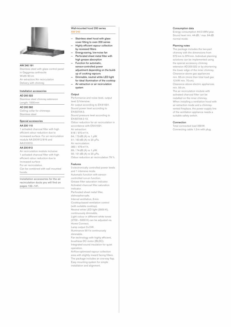
A W 240 191
Stainless steel with glass control panel
in Gaggenau anthracite
Width 90 cm
Air extraction/Air recirculation
Delivery with chimney
Installation accessories
A D 200 322
Stainless steel chimney extension
Length: 1000 mm
A D 200 392
Ceiling collar for chimneys
Stainless steel
Special accessories
A A 200 110
1activatedcharcoalfilterwithhighefficientodourreductionduetoincreased surface. For air recirculation
module AA 200 812/816 and
AA 010 810.
A A 200 812
Air recirculation module inclusive
1activatedcharcoalfilterwithhighefficientodourreductionduetoincreased surface
For air recirculation.
Can be combined with wall mounted
hoods.
Installation accessories for the air recirculation ducts you will find on pages 132–141.
Wall-mounted hood 200 series
A W 240
— Stainless steel hood with glass
coverfittingtooven200series — Highlyefficientvapourcollectionbyrecessedfilters
— Energy-saving, low-noise fan
— Perforatedsheetmetalfilterwithhigh grease absorption
— Function for automatic,
sensor-controlled power
adjustment depending on the build-
up of cooking vapours
— Dimmable, neutral white LED light
for ideal illumination of the cooktop
— Air extraction or air recirculation
system
Output
Performance and noise level, output
level 3/Intensive:
AiroutputaccordingtoEN61591. Sound power level according to
EN60704-3. Sound pressure level according to
EN60704-2-13. Odour reduction for air recirculation in
accordancewithEN61591.Air extraction:
618 / 970 m³/h.
64 / 73 dB (A) re 1 pW.
51/60dB(A)re20μPa.Air recirculation:
383 / 476 m³/h.
69 / 74 dB (A) re 1 pW.
56/61dB(A)re20μPa.Odour reduction air recirculation 79 %.
Features
3 electronically controlled power levels
and 1 intensive mode.
Automatic function with sensor-
controlled run-on function.
Greasefiltersaturationindicator.Activatedcharcoalfiltersaturationindicator.
Perforatedsheetmetalfilter,dishwasher-safe.
Interval ventilation, 6 min.
Cooktop-based ventilation control
(with suitable cooktop).
NeutralwhiteLEDlight(3500K),continuously dimmable.
Lightcolourindifferentwhitetones(2700 – 5000 K) can be adjusted via
Home Connect.
Lamp output 3 x 3 W.
Illuminance 551 lx continuously
dimmable.
Fantechnologywithhighlyefficient,brushless DC motor (BLDC).
Integrated sound insulation for quiet
operation.
Airflow-optimisedvapourcollectionareawithslightlyinwardfacingfilters.Thepackageincludesanone-wayflap.Easy mounting system for simple
installation and alignment.
Consumption data
Energy consumption 44.5 kWh/year.
Sound level min. 44 dB / max. 64 dB
normal mode.
Planning notes
The package includes the two-part
chimney with the dimensions from
572 mm to 874 mm. Individual planning
solutions can be implemented using
the special accessory chimney
extension AD 200 322 or by shortening
the lower edge of the inner chimney.
Clearance above gas appliances
min. 65 cm (more than total load gas
12 kW min. 70 cm).
Clearance above electric appliances
min. 55 cm.
The air recirculation module with
activatedcharcoalfiltercanbeinstalled on the inner chimney.
When installing a ventilation hood with
air extraction mode and a chimney-
ventedfireplace,thepowersupplylineof the ventilation appliance needs a
suitable safety switch.
Connection
Total connected load 269 W.
Connecting cable 1.3 m with plug.
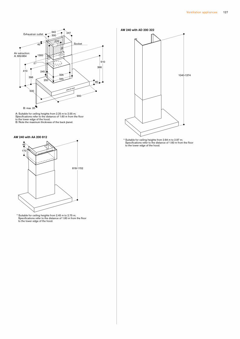
Ventilation appliances 127

A F 210 192
Stainless steel handle bar
Width 90 cm
Air extraction / Air recirculation
A F 210 162
Width 60 cm
Stainless steel handle bar
Air extraction / Air recirculation
Installation accessories
A A 210 460
Lowering frame for 60 cm
flatkitchenhoodA A 210 492
Lowering frame for 90 cm
flatkitchenhoodA A 210 491
Assembly kit for 90 cm upper cabinet
Can be combined with the 90 cm
wideflatkitchenhood200seriesin combination with a 90 cm upper
cabinet.
For left/right assembly in upper
cabinets.
For assembly in the upper cabinet.
If the lowering frame AA 210 492 is
used, the assembly kit is not needed.
Special accessories
A A 211 812
Patented air recirculation module
including1activatedcharcoalfilterwithhighefficientodourreductiondueto increased surface
For air recirculation
Installation accessories for the air recirculation ducts you will find on pages 132–141.
Slide out rangehood 200 series
A F 210
— Unobtrusive slide out hood design
thanks to integrated glass panel in
the steam screen
— Especially quiet operation thanks
to integrated sound insulation
— Steam screen extends by pulling
the handle bar
— Especially high air output
— Energy-saving, low-noise fan
— Function for automatic,
sensor-controlled power
adjustment depending on the build-
up of cooking vapours
— Dimmable, neutral white LED light
for ideal illumination of the cooktop
— The patented lowering frame
allows the slide out rangehood
to disappear completely into the
upper cabinet
— Air extraction or air recirculation
system
— Air recirculation module with
activatedcharcoalfilter:quietandhighlyefficientairrecirculationsolution with odor reduction as
in air extraction mode and long
replacement intervals
Output
3 electronically controlled power levels
and 1 intensive mode.
Appliance width 90cm
Air extraction:
517 / 965 m³/h
57 / 71 dB(A) re 1 pW
Air recirculation:
506 / 876 m³/h
62 / 69 dB(A) re 1 pW
Odour reduction air recirculation: >90%
Appliance width 60cm
Air extraction:
515 / 953 m³/h
57 / 71 dB(A) re 1 pW
Air recirculation
497 / 885 m³/h
62 / 69 dB(A) re 1 pW
Odour reduction air recirculation: >90%
Features
Controls at front.
Automatic function with sensor-
controlled run-on function.
Greasefiltersaturationindicator.Stainlesssteelgreasefilter,dishwasher-safe.
NeutralwhiteLEDlight(3500K),continuously dimmable.
Lamp output 3 x 1.5W.
Illuminance 355 lx.
Light can be switched on separately.
Fantechnologywithhighlyefficient,brushless DC motor (BLDC).
Integrated sound insulation for quiet
operation.
The fan is activated when the steam
screen is extended.
Patented technology for extension of
the steam screen.
Extendable steam screen 198 mm.
Airflow-optimisedinteriorforefficientair circulation and ease of cleaning.
Patented easy mounting system for
simple installation.
Thepackageincludesanone-wayflap.
Consumption data
Energy consumption
41.4 / 40.3 kWh/year.
Sound level min. 41/42 dB /
max. 57 dB normal mode.
Planning notes
For air recirculation an external air
recirculation module is required.
Patented air recirculation module
withactivatedcharcoalfiltercanbeinstalled in the upper cabinet. The
activatedcarbonfiltercanbechangedfrom the front by simply pulling out the
activatedcharcoalfilter.The door of the upper cabinet must
be fully open in order to change the
activatedcharcoalfilter.To be installed in an upper cabinet
without base.
The required cavity depth of the upper
cabinet together with the lowering
frame measures 335 mm.
The required cavity height of the upper
cabinet together with the lowering
frame measures 600 mm.
Minimum clearance between gas
cooktop(s) with more than 39.6 MJ/h
(11 kW) and ventilation hood 700 mm.
For more details, please refer to gas
cooktop(s) installation manual(s).
Clearance above electric appliances
min. 43 cm.
When installing a ventilation hood with
air extraction mode and a chimney-
ventedfireplace,thepowersupplylineof the ventilation appliance needs a
suitable safety switch.
Connection
Total connected load 266/264 W
Connecting cable 1.8 m with plug.

Ventilation appliances 129
Carcass depth 320
dia. 150
Position of LED lights
Back wall panel max. 20 mm
307
280
113
337
290
10
41
16
30
133
14
133
35
dia. 150
898
40
488
290
30
307
349
187
181
378
266
98
524
472
236
26
41
14
140
measurements in mm
Cross-section of upper cabinet for AF210 with AA 211 812 and AA 210 492/460 lowering frame
60
302
89
320
182
≥ 335
≥ 600
≥ 100
≥ 90
measurements in mm
Cross-section of upper cabinet for AF210 with AA 211 812
320
302
182
89
≥ 320
≥ 100
≥ 90
≥ 600
View of upper cabinet from above with AA 211 812
A: Appliance only B: Appliance with lowering frame
measurements in mm
303
202
517
≥ 320 (A)
≥ 335 (B)
= =
measurements in mm
dia. 170
Upper cabinet for AF 210 with lowering frame
85
380
16/19
600/900
198
60
=
= ≥ 335
≥ 540
min. 320
min. 420
* for upper cabinets measuring 90 cm, the AA 210 491 installation set is required in addition
dia. 170
Upper cabinet for AF 210
33
85
320
137 16/19
600/900*
198
=
=
=
= min. 320
dia. 170
min. 420
16/19
900
198
340
16
Upper cabinet for AF210 with assembly kit AA 210 491
dia. 150
598
40
307
140
488
290
349
181
378
266
98
524
472
236
37
26
41
14
30

A C 200 191
Stainless steel and glass
Width 86 cm
Air extraction / Air recirculation
A C 200 161
Stainless steel and glass
Width 52 cm
Air extraction / Air recirculation
Special accessories
A A 211 812
Patented air recirculation module
including1activatedcharcoalfilterwithhighefficientodourreduction due to increased surface
For air recirculation.
Installation accessories for the air recirculation ducts you will find on pages 132–141.
Integrated rangehood 200 series
A C 200
— Can be integrated invisibly
in upper cabinet
— Energy-saving, low-noise fan
— Rimextractionwithflatandeasy-to-clean glass under-side
— Dimmable, neutral white LED light
for ideal illumination of the whole
cooktop
— Air extraction or air recirculation
system
— EnergyefficiencyclassA++
Output
3 electronically controlled power levels
and 1 intensive mode.
Appliance width 86 cm
Air extraction:
610 / 800 m³/h.
64 / 70 dB (A) re 1 pW.
51/57dB(A)re20μPa.Air recirculation:
540 / 790 m³/h.
72 / 77 dB (A) re 1 pW.
59/65dB(A)re20μPa.Odour reduction air recirculation 94%.
Appliance width 52 cm
Air extraction:
540 / 730 m³/h.
64 / 70 dB (A) re 1 pW.
51/57dB(A)re20μPa.Air recirculation:
530 / 690 m³/h.
72 / 77 dB (A) re 1 pW.
59/64dB(A)re20μPa.Odour reduction air recirculation 92%.
Features
Remote control is available as a special
accessory.
Interval ventilation, 6 min.
Run-on function, 6 min.
Greasefiltersaturationindicator.Metalgreasefilter,dishwasher-safe.Glassfiltercover.NeutralwhiteLEDlight(4000K),dimmable.
Lamp output 2 x 1 W.
Illuminance 266 lx. / 244 lx.
Fantechnologywithhighlyefficient,brushless DC motor (BLDC).
Consumption data
Energy consumption
31.4 / 29.6 kWh/year.
Sound level min. 41 / 44 dB /
max. 64 dB normal mode.
Planning notes
Patented air recirculation module
withactivatedcharcoalfiltercanbeinstalled in the upper cabinet. The
activatedcarbonfiltercanbechangedfrom the front by simply pulling out the
filterdrawer.The door of the upper cabinet must
be fully open in order to change the
activatedcharcoalfilter.Can be integrated invisibly in upper
cabinet.
Vario cooktops with intensive
production of vapours like VR/
VP should be placed in the middle
beneath the hood (in this case air
recirculation is not recommended).
Minimum clearance between gas
cooktop(s) with more than 39.6 MJ/h
(11 kW) and ventilation hood 700 mm.
For more details, please refer to gas
cooktop(s) installation manual(s).
Clearance above electric appliances
min. 500 mm.
When installing a ventilation hood with
air extraction mode and a chimney-
ventedfireplace,thepowersupplylineof the ventilation appliance needs a
suitable safety switch.
Connection
Total connected load 172 W.
Connecting cable 1.0 m with plug.
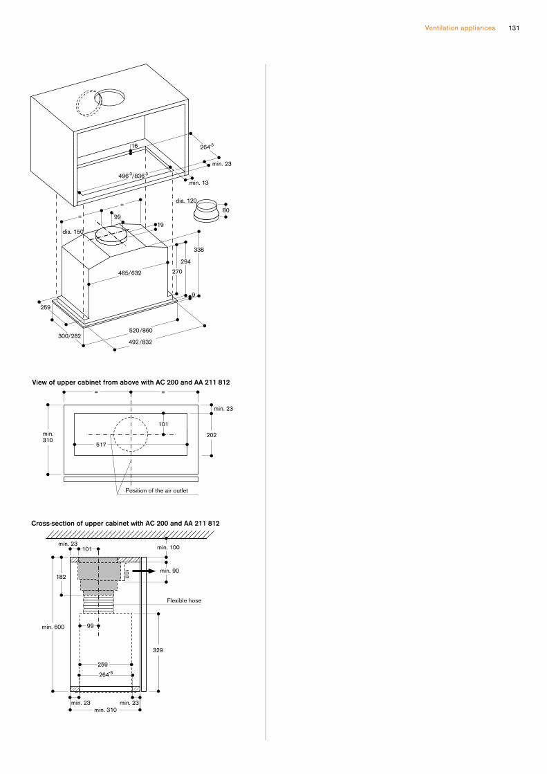
Ventilation appliances 131
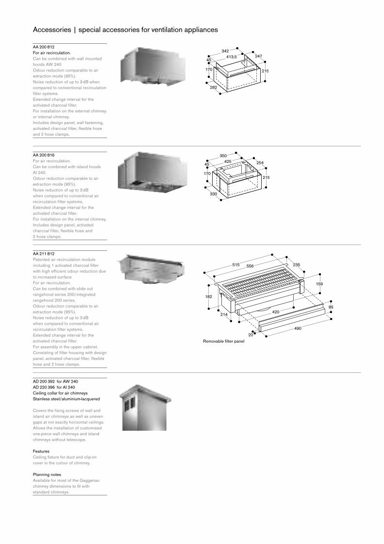
Accessories | special accessories for ventilation appliances
A A 200 812
For air recirculation.
Can be combined with wall mounted
hoods AW 240
Odour reduction comparable to air
extraction mode (95%).
Noisereductionofupto3dBwhencompared to conventional recirculation
filtersystems.Extended change interval for the
activatedcharcoalfilter.For installation on the external chimney
or internal chimney.
Includes design panel, wall fastening,
activatedcharcoalfilter,flexiblehoseand 2 hose clamps.
A A 200 816
For air recirculation.
Can be combined with island hoods
AI 240.
Odour reduction comparable to air
extraction mode (95%).
Noisereductionofupto3dBwhen compared to conventional air
recirculationfiltersystems.Extended change interval for the
activatedcharcoalfilter.For installation on the internal chimney.
Includes design panel, activated
charcoalfilter,flexiblehoseand 2 hose clamps.
A A 211 812
Patented air recirculation module
including1activatedcharcoalfilterwithhighefficientodourreductiondueto increased surface
For air recirculation.
Can be combined with slide out
rangehood series 200/integrated
rangehood 200 series.
Odour reduction comparable to air
extraction mode (95%).
Noisereductionofupto3dBwhen compared to conventional air
recirculationfiltersystems.Extended change interval for the
activatedcharcoalfilter.For assembly in the upper cabinet.
Consistingoffilterhousingwithdesignpanel,activatedcharcoalfilter,flexiblehose and 2 hose clamps.
A D 200 392 for AW 240
A D 220 396 for AI 240
Ceiling collar for air chimneys
Stainless steel/aluminium-lacquered
Coversthefixingscrewsofwallandisland air chimneys as well as uneven
gaps at not exactly horizontal ceilings.
Allows the installation of customised
one-piece wall chimneys and island
chimneys without telescope.
Features
Ceilingfixtureforductandclip-oncover in the colour of chimney.
Planning notes
Available for most of the Gaggenau
chimneydimensionstofitwithstandard chimneys.
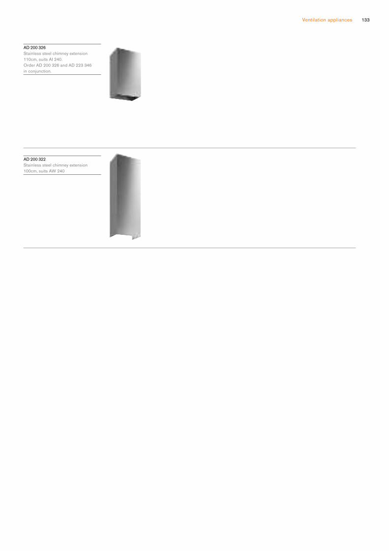
Ventilation appliances 133
A D 200 326
Stainless steel chimney extension
110cm, suits AI 240.
Order AD 200 326 and AD 223 346
in conjunction.
A D 200 322
Stainless steel chimney extension
100cm, suits AW 240
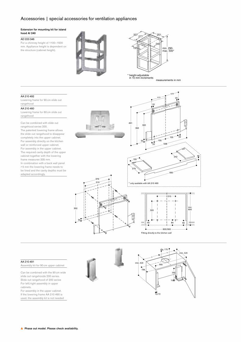
Accessories | special accessories for ventilation appliances
Phase out model. Please check availability.
Extension for mounting kit for island hood AI 240
A D 223 346
For a chimney height of 1100–1500
mm. Appliance height is dependent on
the structure (cabinet height).
A A 210 492
Lowering frame for 90 cm slide out
rangehood
A A 210 460
Lowering frame for 60 cm slide out
rangehood
Can be combined with slide out
rangehood series 200.
The patented lowering frame allows
the slide out rangehood to disappear
completely into the upper cabinet.
For assembly directly on the kitchen
wall or reinforced upper cabinet.
For assembly in the upper cabinet.
The required cavity depth of the upper
cabinet together with the lowering
frame measures 335 mm.
In combination with a back wall panel
> 5 mm the lowering frame needs to
be lined and the cavity depths must be
adapted accordingly.
A A 210 491
Assembly kit for 90 cm upper cabinet
Can be combined with the 90 cm wide
slide out rangehoods 200 series.
Slide out rangehood of 200 series
For left/right assembly in upper
cabinets.
For assembly in the upper cabinet.
If the lowering frame AA 210 490 is
used, the assembly kit is not needed
min. 290-
max. 500*
251277
337
191
249

Ventilation appliances 135
A D 700 051
Wall outlet
Stainless steel
DN200round
Littlelossofairflowduetolargestainless steel outlet louvres.
Features
Weatherproof stainless steel louvres.
Integratedone-wayflap.ConnectingpieceDN200round
Planning notes
For use with telescopic wall-duct
AD 702
Wall breakthrough ø 210 mm
A D 702 052
Telescopic wall-duct
Stainless steel
DN200round
Features
ConnectingpieceDN200round.Integratedone-wayflap.
Planning notes
For use with wall outlet AD 700 051 or
remote fan unit AR 401.
AD 750 054
Wall outlet with telescopic duct
Stainless steel/plastic
DN150roundOptimal temperature insulation.
Hermetically sealed by an optimized
built-in heat retention system. Flat
stainless
steelcoverwithminimaleffecttothe aesthetics of the building exterior
facade.
Features
Weatherproof stainless steel louvres.
3-timesinsulatingBackflowsystem.Magnetic opening and closing.
Definedopeningpressure(65Pa)prevents rattling.
Fullopeningevenatlowflowrates.Telescopic wall duct 350 - 500 mm for
roundpipeconnectionpieceDN150.
Planning notes
Conform to blower-door test.
ForconnectionofroundpipeDN150orflatpipeDN150.Wallbreakthroughø 155 mm.
300-500
Silikon
ø 210
ø 200
Wall outlet
Walloutletsareavailablethataresuitableforprovidingaclean,efficientandunobtrusivemethodofroutingductingthroughoutsidewalls. The aperture should always correspond to, or be bigger than, the nominal width of the type of pipe used.
measurements in mm
:A Drilling ø 155
ø 152 (A)
180
22190
190
350-500
237 80
180
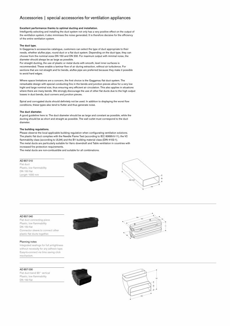
Accessories | special accessories for ventilation appliances
Excellent performance thanks to optimal ducting and installation.Intelligentlyselectingandinstallingtheductsystemnotonlyhasaverypositiveeffectontheoutputoftheventilationsystem;italsominimisesthenoisegenerated.Itisthereforedecisivefortheefficiencyof the entire ventilation system.
The duct type.
In Gaggenau’s accessories catalogue, customers can select the type of duct appropriate to their
needs,whetheraluflexpipe,roundductoraflatductsystem.Dependingontheducttype,theycanchoosefromthenominalsizesDN150andDN200.Formaximumoutputwithminimalnoise,thediameter should always be as large as possible.
For straight ducting, the use of plastic or metal ducts with smooth, level inner surfaces is
recommended.Theseenablealaminarflowofairduringextraction,withoutairturbulence.Forsectionsthatarenotstraightandforbends,aluflexpipearepreferredbecausetheymakeitpossibleto avoid hard edges.
Wherespacelimitationsareaconcern,thefirstchoiceistheGaggenauflatductsystem.Theremarkabledesignwithspecialconductingfinsinthebendsandjunctionpiecesallowforaverylowhightandlargenominalsize,thusensuringveryefficientaircirculation.Thisalsoappliesinsituationswheretherearemanybends.Westronglydiscouragetheuseofotherflatductsduetothehighoutputlosses in duct bends, duct corners and junction pieces.
Spiralandcorrugatedductsshoulddefinitelynotbeused.Inadditiontodisplayingtheworstflowconditions,thesetypesalsotendtoflutterandthusgeneratenoise.
The duct diameter.
A good guideline here is: The duct diameter should be as large and constant as possible, while the
ducting should be as short and straight as possible. The wall outlet must correspond to the duct
diameter.
The building regulations.
Pleaseobservethelocalapplicablebuildingregulationwhenconfiguratingventilationsolutions.TheplasticflatductcomplieswiththeNeedleFlameTest(accordingtoIEC60695-5-11),theV2flammabilityclass(accordingtoUL94)andtheB1buildingmaterialclass(DIN4102-1).The metal ducts are particularly suitable for Vario downdraft and Table ventilation in countries with
increasedfireprotectionrequirements.The metal ducts are non-combustible and suitable for all combinations.
A D 857 010
Flat duct
Plastic,lowflammability DN150flat Length 1000 mm
A D 857 040
Flat duct connecting piece
Plastic,lowflammability DN150flat Connector sleeve to connect other
plasticflatductstogether.
Planning notes
Integrated sealings for full airtightness
without necessity for any adhesiv tape.
Easy-to-connect via time saving click
mechanism.
A D 857 030
Flat duct bend 90° vertical
Plastic,lowflammability DN150flat
500/1000
222
89
223
99
249
71
90
161
222
89
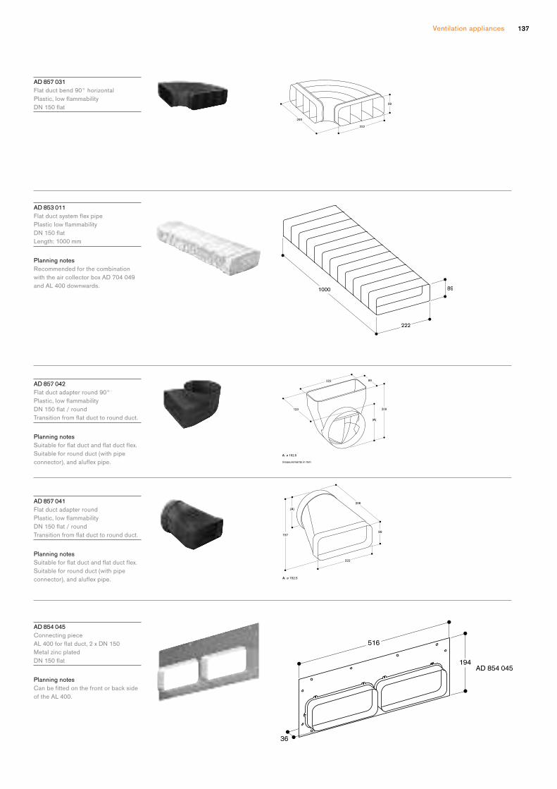
Ventilation appliances 137137
A D 857 031
Flat duct bend 90° horizontal
Plastic,lowflammability DN150flat
A D 853 011
FlatductsystemflexpipePlasticlowflammabilityDN150flatLength: 1000 mm
Planning notes
Recommended for the combination
with the air collector box AD 704 049
and AL 400 downwards.
A D 857 042
Flat duct adapter round 90°
Plastic,lowflammability DN150flat/round
Transitionfromflatducttoroundduct.
Planning notes
Suitableforflatductandflatductflex.Suitable for round duct (with pipe
connector),andaluflexpipe.
A D 857 041
Flat duct adapter round
Plastic,lowflammability DN150flat/round
Transitionfromflatducttoroundduct.
Planning notes
Suitableforflatductandflatductflex.Suitable for round duct (with pipe
connector),andaluflexpipe.
A D 854 045
Connecting piece
AL400forflatduct,2xDN150 Metal zinc plated
DN150flat
Planning notes
Canbefittedonthefrontorbacksideof the AL 400.
measurements in mm
293
222
89
A: ø 152.5
measurements in mm
123
( A )
89
209
222
A: ø 152.5
157
(A)
89
206
222

Accessories | special accessories for ventilation appliances
A D 854 043
Connecting piece
AL400forflatduct,2xDN150
Metal zinc plated
DN150flat
Planning notes
CanbefittedontheundersideoftheAL 400.
Set of two.
A D 854 046
Flat duct connecting piece for
VL 414
Metal zinc plated with plastic
DN150flat
Planning notes
One piece needed for each
VL414tobeconnectedtoflatducts.Outlet to the left/right possible.
Ventilation moulding
A A 414 010
Ventilation moulding for VL 414 next to
gas appliance.
Ventilation moulding
L S 041 001
Ventilation moulding for VL 200 next to
gas appliance.
A D 410 040
Flexible connecting piece for VL 200
DN150flat
A D 851 041
Connecting piece VL 200 for extension
withflatductDN150forextradeepworktop
flat duct DN 150 for extra deep workt

Ventilation appliances 139
A A 010 410
Air exhaust grill air recirculation
Stainless steel-coloured, 90 cm,
includinginstallationfittings,heightadjustable.
A A 409 401
Furniture support for table ventilation
AL 400 90 cm
Can be combined with table ventilation
AL 400.
Recommended as bearer for the
worktop, instead of a cabinet frame.
A A 409 431
Furniture support for table ventilation
AL 400 120 cm
Can be combined with table ventilation
AL 400.
Recommended as bearer for the
worktop, instead of a cabinet frame.
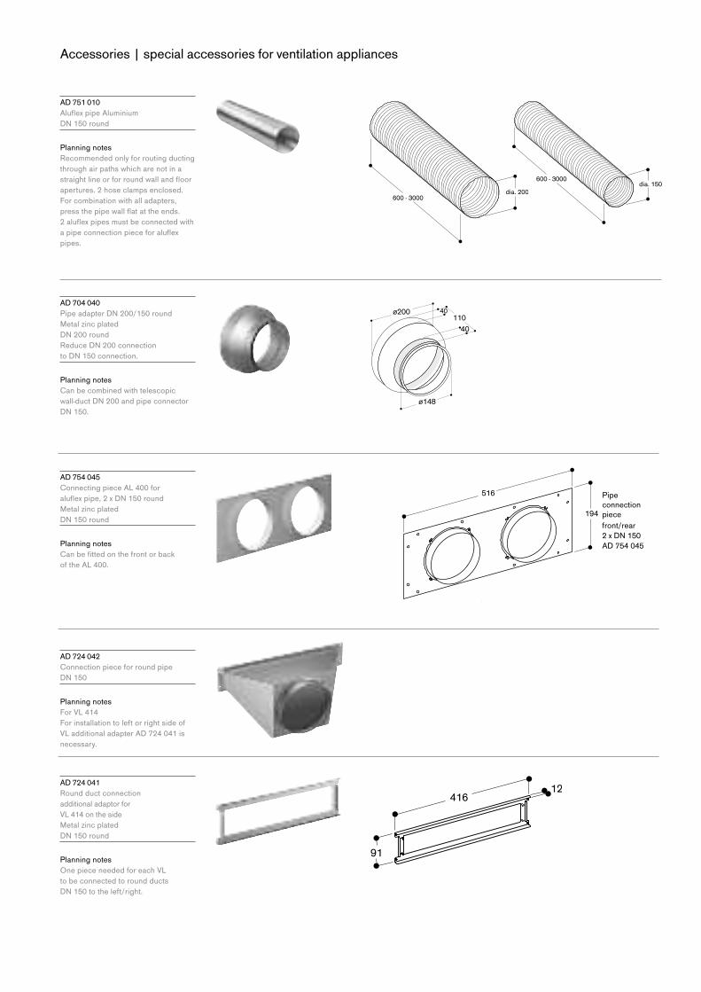
Accessories | special accessories for ventilation appliances
A D 751 010
AluflexpipeAluminiumDN150round
Planning notes
Recommended only for routing ducting
through air paths which are not in a
straightlineorforroundwallandfloorapertures. 2 hose clamps enclosed.
For combination with all adapters,
pressthepipewallflatattheends. 2aluflexpipesmustbeconnectedwithapipeconnectionpieceforaluflexpipes.
A D 704 040
PipeadapterDN200/150round Metal zinc plated
DN200round ReduceDN200connection toDN150connection.
Planning notes
Can be combined with telescopic
wall-ductDN200andpipeconnectorDN150.
A D 754 045
Connecting piece AL 400 for
aluflexpipe,2xDN150round
Metal zinc plated
DN150round
Planning notes
Canbefittedonthefrontorback of the AL 400.
A D 724 042
Connection piece for round pipe
DN150
Planning notes
For VL 414
For installation to left or right side of
VL additional adapter AD 724 041 is
necessary.
A D 724 041
Round duct connection
additional adaptor for
VL 414 on the side
Metal zinc plated
DN150round
Planning notes
One piece needed for each VL
to be connected to round ducts
DN150totheleft/right.

Ventilation appliances 141
A D 990 090
Adhesive tape for duct components
Plastic
10 m/roll
Planning notes
In order that ducting is well sealed and
air leaks are consequently prevented,
the adhesive tape AD 990 090 is
necessary at all pipe connection piece
points. The adhesive tape is heat- and
UV-resistant.
A D 704 048
Air collector box round duct for AL 400
Metal zinc plated
DN150round
Planning notes
2xDN150roundductairintake. To connect 1 x AL 400 to AR 403/413.
1xDN200airoutlet.
A D 704 049
AircollectorflatductforAL400Metal zinc plated
DN150flat
Planning notes
2xDN150flatductairintakeTo connect 1 x AL 400 to remote fan
AR 403 / AR 413 bottom side.
To connect the AL 400 and the remote
fanAR403/AR413theflexduct AD 853 011 is possible and can be
shortened to the appropriate length.
The package includes four cable straps
forfixingtheflexductAD853011.
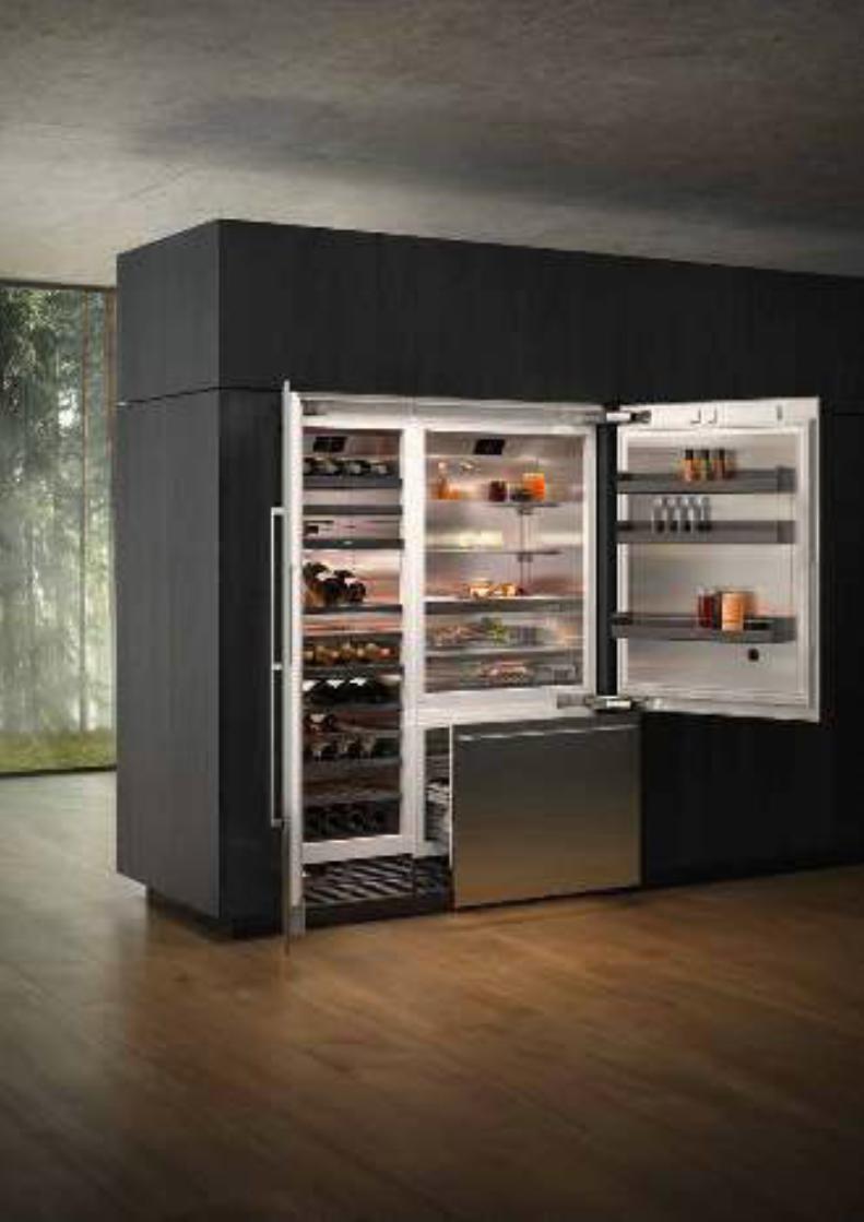
143
The cooling appliances
Vario cooling 400 series 144
Wine climate cabinet 400 series 148
Wine climate cabinet 200 series 149
Overview – niche requirements 151
Planning notes 152
Additional planning notes Vario cooling 400 series 156
Additional planning notes Vario cooling 200 series 160
Accessories | special accessories 162
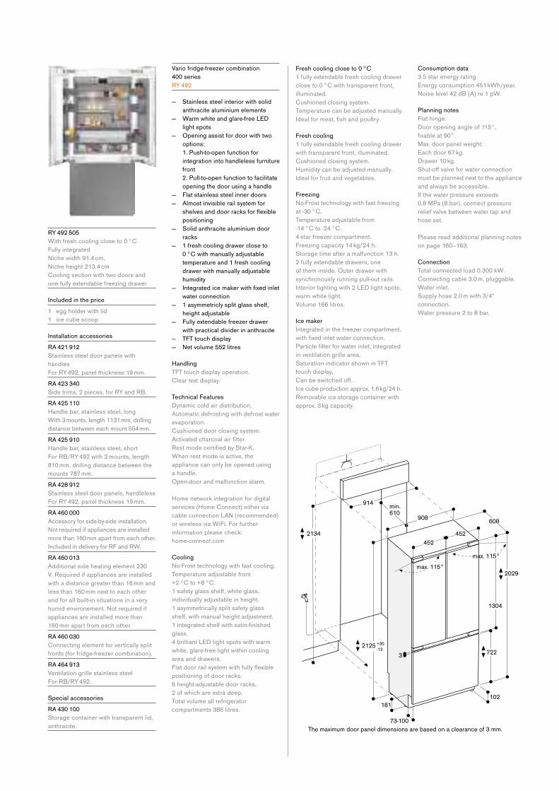
R Y 492 505
With fresh cooling close to 0 °C
Fully integrated
Nichewidth91.4cm, Nicheheight213.4cmCooling section with two doors and
one fully extendable freezing drawer
Included in the price
1 egg holder with lid
1 ice cube scoop
Installation accessories
R A 421 912
Stainless steel door panels with
handles
For RY 492, panel thickness 19 mm.
R A 423 340
Side trims, 2 pieces, for RY and RB.
R A 425 110
Handle bar, stainless steel, long
With 3 mounts, length 1131 mm, drilling
distance between each mount 554 mm.
R A 425 910
Handle bar, stainless steel, short
For RB/RY 492 with 2 mounts, length
810 mm, drilling distance between the
mounts 787 mm.
R A 428 912
Stainless steel door panels, handleless
For RY 492, panel thickness 19 mm.
R A 460 000
Accessory for side-by-side installation.
Notrequiredifappliancesareinstalledmore than 160 mm apart from each other.
Included in delivery for RF and RW.
R A 460 013
Additional side heating element 230
V. Required if appliances are installed
with a distance greater than 16 mm and
less than 160 mm next to each other
and for all built-in situations in a very
humidenvironement.Notrequiredifappliances are installed more than
160 mm apart from each other.
R A 460 030
Connecting element for vertically split
fronts (for fridge-freezer combination).
R A 464 913
Ventilation grille stainless steel
For RB/RY 492.
Special accessories
R A 430 100
Storage container with transparent lid,
anthracite.
Vario fridge-freezer combination
400 series
R Y 492
— Stainless steel interior with solid
anthracite aluminium elements
— Warm white and glare-free LED
light spots
— Opening assist for door with two
options:
1. Push-to-open function for
integration into handleless furniture
front
2. Pull-to-open function to facilitate
opening the door using a handle
— Flat stainless steel inner doors
— Almost invisible rail system for
shelvesanddoorracksforflexiblepositioning
— Solid anthracite aluminium door
racks
— 1 fresh cooling drawer close to
0 °C with manually adjustable
temperature and 1 fresh cooling
drawer with manually adjustable
humidity
— Integratedicemakerwithfixedinletwater connection
— 1 asymmetricly split glass shelf,
height adjustable
— Fully extendable freezer drawer
with practical divider in anthracite
— TFT touch display
— Netvolume552litres
Handling
TFT touch display operation.
Clear text display.
Technical Features
Dynamic cold air distribution.
Automatic defrosting with defrost water
evaporation.
Cushioned door closing system.
Activatedcharcoalairfilter.RestmodecertifiedbyStar-K.When rest mode is active, the
appliance can only be opened using
a handle.
Open-door and malfunction alarm.
Home network integration for digital
services (Home Connect) either via
cableconnectionLAN(recommended)or wireless via WiFi. For further
information please check:
home-connect.com
Cooling
No-Frosttechnologywithfastcooling.Temperature adjustable from
+2 °C to +8 °C.
1 safety glass shelf, white glass,
individually adjustable in height.
1 asymmetrically split safety glass
shelf, with manual height adjustment.
1integratedshelfwithsatin-finishedglass.
4 brilliant LED light spots with warm
white, glare-free light within cooling
area and drawers.
Flatdoorrailsystemwithfullyflexiblepositioning of door racks.
6 height-adjustable door racks,
2 of which are extra deep.
Total volume all refrigerator
compartments 386 litres.
Fresh cooling close to 0 °C
1 fully extendable fresh cooling drawer
close to 0 °C with transparent front,
illuminated.
Cushioned closing system.
Temperature can be adjusted manually.
Idealformeat,fishandpoultry.
Fresh cooling
1 fully extendable fresh cooling drawer
with transparent front, illuminated.
Cushioned closing system.
Humidity can be adjusted manually.
Ideal for fruit and vegetables.
Freezing
No-Frosttechnologywithfastfreezingat -30 °C.
Temperature adjustable from
-14 °C to -24 °C.
4-star freezer compartment.
Freezing capacity 14 kg/24 h.
Storage time after a malfunction 13 h.
2 fully extendable drawers, one
of them inside. Outer drawer with
synchronously running pull-out rails.
Interior lighting with 2 LED light spots,
warm white light.
Volume 166 litres.
Ice maker
Integrated in the freezer compartment,
withfixedinletwaterconnection.Particlefilterforwaterinlet,integratedin ventilation grille area.
Saturation indicator shown in TFT
touch display.
Canbeswitchedoff.Ice cube production approx. 1.6 kg/24 h.
Removable ice storage container with
approx. 3 kg capacity.
Consumption data
3.5 star energy rating
Energy consumption 451 kWh/year.
Noiselevel42dB(A)re1pW.
Planning notes
Flat hinge.
Door opening angle of 115°,
fixableat90°.Max. door panel weight:
Each door 67 kg.
Drawer 10 kg.
Shut-offvalveforwaterconnectionmust be planned next to the appliance
and always be accessible.
If the water pressure exceeds
0.8 MPa (8 bar), connect pressure
relief valve between water tap and
hose set.
Please read additional planning notes
on page 160–163.
Connection
Total connected load 0.300 kW.
Connecting cable 3.0 m, pluggable.
Water inlet.
Supply hose 2.0 m with 3/4"
connection.
Water pressure 2 to 8 bar.
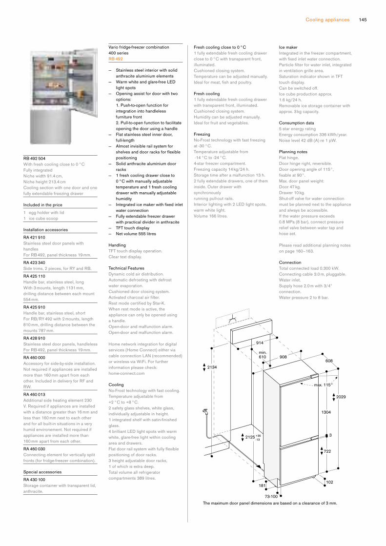
145Cooling appliances
R B 492 504
With fresh cooling close to 0 °C
Fully integrated
Nichewidth91.4cm, Nicheheight213.4cmCooling section with one door and one
fully extendable freezing drawer
Included in the price
1 egg holder with lid
1 ice cube scoop
Installation accessories
R A 421 910
Stainless steel door panels with
handles
For RB 492, panel thickness 19 mm.
R A 423 340
Side trims, 2 pieces, for RY and RB.
R A 425 110
Handle bar, stainless steel, long
With 3 mounts, length 1131 mm,
drilling distance between each mount
554 mm.
R A 425 910
Handle bar, stainless steel, short
For RB/RY 492 with 2 mounts, length
810 mm, drilling distance between the
mounts 787 mm.
R A 428 910
Stainless steel door panels, handleless
For RB 492, panel thickness 19 mm.
R A 460 000
Accessory for side-by-side installation.
Notrequiredifappliancesareinstalledmore than 160 mm apart from each
other. Included in delivery for RF and
RW.
R A 460 013
Additional side heating element 230
V. Required if appliances are installed
with a distance greater than 16 mm and
less than 160 mm next to each other
and for all built-in situations in a very
humidenvironement.Notrequiredifappliances are installed more than
160 mm apart from each other.
R A 460 030
Connecting element for vertically split
fronts (for fridge-freezer combination).
Special accessories
R A 430 100
Storage container with transparent lid,
anthracite.
Vario fridge-freezer combination
400 series
R B 492
— Stainless steel interior with solid
anthracite aluminium elements
— Warm white and glare-free LED
light spots
— Opening assist for door with two
options:
1. Push-to-open function for
integration into handleless
furniture front
2. Pull-to-open function to facilitate
opening the door using a handle
— Flat stainless steel inner door,
full-length
— Almost invisible rail system for
shelvesanddoorracksforflexiblepositioning
— Solid anthracite aluminium door
racks
— 1 fresh cooling drawer close to
0 °C with manually adjustable
temperature and 1 fresh cooling
drawer with manually adjustable
humidity
— Integratedicemakerwithfixedinletwater connection
— Fully extendable freezer drawer
with practical divider in anthracite
— TFT touch display
— Netvolume555litres
Handling
TFT touch display operation.
Clear text display.
Technical Features
Dynamic cold air distribution.
Automatic defrosting with defrost
water evaporation.
Cushioned door closing system.
Activatedcharcoalairfilter.RestmodecertifiedbyStar-K.When rest mode is active, the
appliance can only be opened using
a handle.
Open-door and malfunction alarm.
Open-door and malfunction alarm.
Home network integration for digital
services (Home Connect) either via
cableconnectionLAN(recommended)or wireless via WiFi. For further
information please check:
home-connect.com
Cooling
No-Frosttechnologywithfastcooling.Temperature adjustable from
+2 °C to +8 °C.
2 safety glass shelves, white glass,
individually adjustable in height.
1integratedshelfwithsatin-finishedglass.
4 brilliant LED light spots with warm
white, glare-free light within cooling
area and drawers.
Flatdoorrailsystemwithfullyflexiblepositioning of door racks.
3 height adjustable door racks,
1 of which is extra deep.
Total volume all refrigerator
compartments 389 litres.
Fresh cooling close to 0 °C
1 fully extendable fresh cooling drawer
close to 0 °C with transparent front,
illuminated.
Cushioned closing system.
Temperature can be adjusted manually.
Idealformeat,fishandpoultry.
Fresh cooling
1 fully extendable fresh cooling drawer
with transparent front, illuminated.
Cushioned closing system.
Humidity can be adjusted manually.
Ideal for fruit and vegetables.
Freezing
No-Frosttechnologywithfastfreezingat -30 °C.
Temperature adjustable from
-14 °C to -24 °C.
4-star freezer compartment.
Freezing capacity 14 kg/24 h.
Storage time after a malfunction 13 h.
2 fully extendable drawers, one of them
inside. Outer drawer with
synchronously
running pull-out rails.
Interior lighting with 2 LED light spots,
warm white light.
Volume 166 litres.
Ice maker
Integrated in the freezer compartment,
withfixedinletwaterconnection.Particlefilterforwaterinlet,integratedin ventilation grille area.
Saturation indicator shown in TFT
touch display.
Canbeswitchedoff.Ice cube production approx.
1.6 kg/24 h.
Removable ice storage container with
approx. 3 kg capacity.
Consumption data
5 star energy rating
Energy consumption 336 kWh/year.
Noiselevel42dB(A)re1pW.
Planning notes
Flat hinge.
Door hinge right, reversible.
Door opening angle of 115°,
fixableat90°.Max. door panel weight:
Door 47 kg.
Drawer 10 kg.
Shut-offvalveforwaterconnectionmust be planned next to the appliance
and always be accessible.
If the water pressure exceeds
0.8 MPa (8 bar), connect pressure
relief valve between water tap and
hose set.
Please read additional planning notes
on page 160–163.
Connection
Total connected load 0.300 kW.
Connecting cable 3.0 m, pluggable.
Water inlet.
Supply hose 2.0 m with 3/4"
connection.
Water pressure 2 to 8 bar.
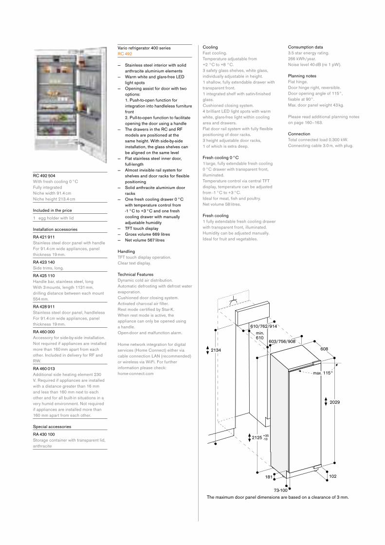
R C 492 504
With fresh cooling 0 °C
Fully integrated
Nichewidth91.4cm Nicheheight213.4cm
Included in the price
1 egg holder with lid
Installation accessories
R A 421 911
Stainless steel door panel with handle
For 91.4 cm wide appliances, panel
thickness 19 mm.
R A 423 140
Side trims, long.
R A 425 110
Handle bar, stainless steel, long
With 3 mounts, length 1131 mm,
drilling distance between each mount
554 mm.
R A 428 911
Stainless steel door panel, handleless
For 91.4 cm wide appliances, panel
thickness 19 mm.
R A 460 000
Accessory for side-by-side installation.
Notrequiredifappliancesareinstalledmore than 160 mm apart from each
other. Included in delivery for RF and
RW.
R A 460 013
Additional side heating element 230
V. Required if appliances are installed
with a distance greater than 16 mm
and less than 160 mm next to each
other and for all built-in situations in a
veryhumidenvironment.Notrequiredif appliances are installed more than
160 mm apart from each other.
Special accessories
R A 430 100
Storage container with transparent lid,
anthracite
Vario refrigerator 400 series
R C 492
— Stainless steel interior with solid
anthracite aluminium elements
— Warm white and glare-free LED
light spots
— Opening assist for door with two
options:
1. Push-to-open function for
integration into handleless furniture
front
2. Pull-to-open function to facilitate
opening the door using a handle
— The drawers in the RC and RF
models are positioned at the
same height. With side-by-side
installation, the glass shelves can
be aligned on the same level
— Flat stainless steel inner door,
full-length
— Almost invisible rail system for
shelvesanddoorracksforflexiblepositioning
— Solid anthracite aluminium door
racks
— One fresh cooling drawer 0 °C
with temperature control from
-1 °C to +3 °C and one fresh
cooling drawer with manually
adjustable humidity
— TFT touch display
— Gross volume 669 litres
— Netvolume567litres
Handling
TFT touch display operation.
Clear text display.
Technical Features
Dynamic cold air distribution.
Automatic defrosting with defrost water
evaporation.
Cushioned door closing system.
Activatedcharcoalairfilter.RestmodecertifiedbyStar-K.When rest mode is active, the
appliance can only be opened using
a handle.
Open-door and malfunction alarm.
Home network integration for digital
services (Home Connect) either via
cableconnectionLAN(recommended)or wireless via WiFi. For further
information please check:
home-connect.com
Cooling
Fast cooling.
Temperature adjustable from
+2 °C to +8 °C.
3 safety glass shelves, white glass,
individually adjustable in height.
1 shallow, fully extendable drawer with
transparent front.
1integratedshelfwithsatin-finishedglass.
Cushioned closing system.
4 brilliant LED light spots with warm
white, glare-free light within cooling
area and drawers.
Flatdoorrailsystemwithfullyflexiblepositioning of door racks.
3 height adjustable door racks,
1 of which is extra deep.
Fresh cooling 0 °C
1 large, fully extendable fresh cooling
0 °C drawer with transparent front,
illuminated.
Temperature control via central TFT
display, temperature can be adjusted
from -1 °C to +3 °C.
Idealformeat,fishandpoultry.Netvolume58litres.
Fresh cooling
1 fully extendable fresh cooling drawer
with transparent front, illuminated.
Humidity can be adjusted manually.
Ideal for fruit and vegetables.
Consumption data
3.5 star energy rating.
266 kWh/year.
Noiselevel40dB(re1pW).
Planning notes
Flat hinge.
Door hinge right, reversible.
Door opening angle of 115°,
fixableat90°.Max. door panel weight 43 kg.
Please read additional planning notes
on page 160–163.
Connection
Total connected load 0.300 kW.
Connecting cable 3.0 m, with plug.
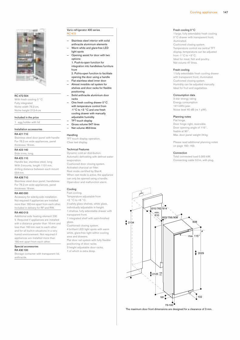
147Cooling appliances
max. 115°
The maximum door front dimensions are designed for a clearance of 3 mm.
min.610
2029
608
603/756/908
2125
102
+35-13
181
610/762/914
2134
73-100
Vario refrigerator 400 series
R C 472
— Stainless steel interior with solid
anthracite aluminium elements
— Warm white and glare-free LED
light spots
— Opening assist for door with two
options:
1. Push-to-open function for
integration into handleless furniture
front
2. Pull-to-open function to facilitate
opening the door using a handle
— Flat stainless steel inner door
— Almost invisible rail system for
shelvesanddoorracksforflexiblepositioning
— Solid anthracite aluminium door
racks
— One fresh cooling drawer 0°C
with temperature control from
-1°C to +3 °C and one fresh
cooling drawer with manually
adjustable humidity
— TFT touch display
— Gross volume 547 litres
— Netvolume463litres
Handling
TFT touch display operation.
Clear text display.
Technical Features
Dynamic cold air distribution.
Automatic defrosting with defrost water
evaporation.
Cushioned door closing system.
Activatedcharcoalairfilter.RestmodecertifiedbyStar-K.When rest mode is active, the appliance
can only be opened using a handle.
Open-door and malfunction alarm.
Cooling
Fast cooling.
Temperature adjustable from
+2 °C to +8 °C.
3 safety glass shelves, white glass,
individually adjustable in height.
1 shallow, fully extendable drawer with
transparent front.
1integratedshelfwithsatin-finishedglass.
Cushioned closing system.
4 brilliant LED light spots with warm
white, glare-free light within cooling
area and drawers.
Flatdoorrailsystemwithfullyflexiblepositioning of door racks.
3 height adjustable door racks,
1 of which is extra deep.
Fresh cooling 0°C
1 large, fully extendable fresh cooling
0°C drawer with transparent front,
illuminated.
Cushioned closing system.
Temperature control via central TFT
display, temperature can be adjusted
from -1°C to +3°C.
Idealformeat,fishandpoultry.Netvolume47litres.
Fresh cooling
1 fully extendable fresh cooling drawer
with transparent front, illuminated.
Cushioned closing system.
Humidity can be adjusted manually.
Ideal for fruit and vegetables.
Consumption data
3 star energy rating
Energy consumption
141 kWh/year.
Noiselevel40dB(re1pW).
Planning notes
Flat hinge.
Door hinge right, reversible.
Door opening angle of 115°,
fixableat90°.Max. door panel weight 24 kg.
Please read additional planning notes
on page 160–163.
Connection
Total connected load 0.300 kW.
Connecting cable 3.0 m, with plug.
R C 472 504
With fresh cooling 0 °C
Fully integrated
Nichewidth76.2cm, Nicheheight213.4cm
Included in the price
1 egg holder with lid
Installation accessories
R A 421 710
Stainless steel door panel with handle
For 76.2 cm wide appliances, panel
thickness 19 mm.
R A 423 140
Side trims, long.
R A 425 110
Handle bar, stainless steel, long
With 3 mounts, length 1131 mm,
drilling distance between each mount
554 mm.
R A 428 710
Stainless steel door panel, handleless
For 76.2 cm wide appliances, panel
thickness 19 mm.
R A 460 000
Accessory for side-by-side installation.
Notrequiredifappliancesareinstalledmore than 160 mm apart from each other.
Included in delivery for RF and RW.
R A 460 013
Additional side heating element 230
V. Required if appliances are installed
with a distance greater than 16 mm and
less than 160 mm next to each other
and for all built-in situations in a very
humidenvironement.Notrequiredifappliances are installed more than
160 mm apart from each other.
Special accessories
R A 430 100
Storage container with transparent lid,
anthracite.
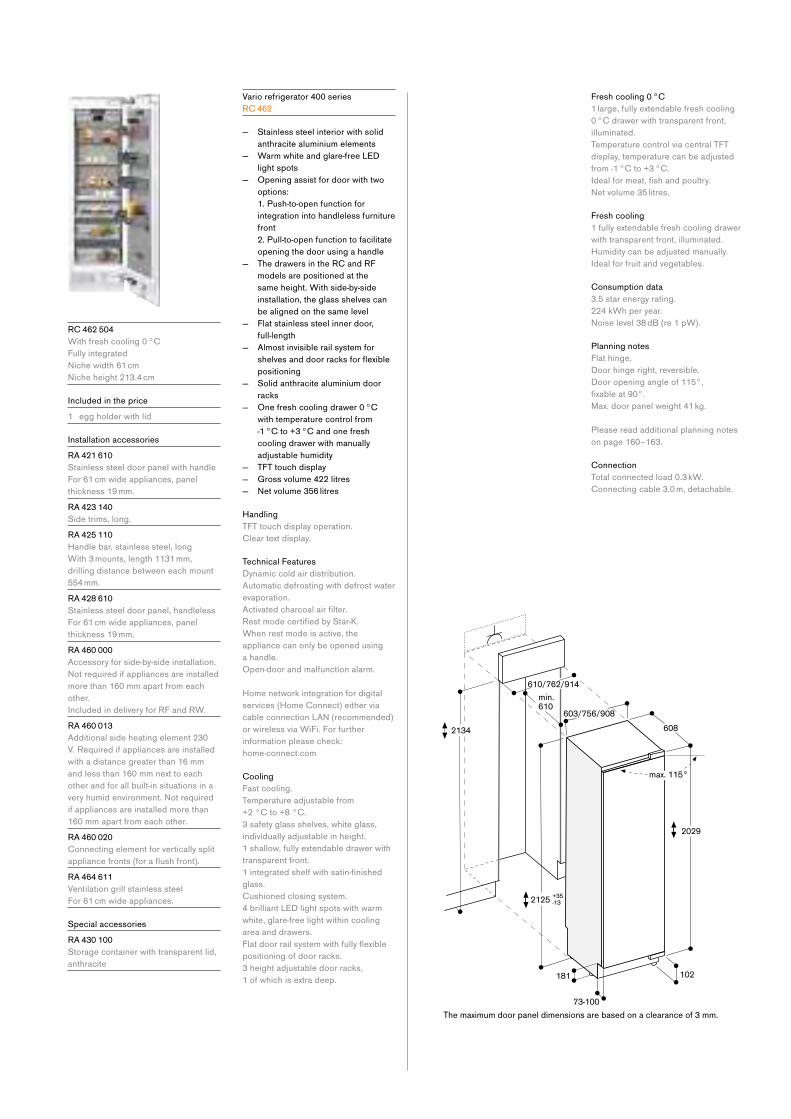
Fresh cooling 0 °C
1 large, fully extendable fresh cooling
0 °C drawer with transparent front,
illuminated.
Temperature control via central TFT
display, temperature can be adjusted
from -1 °C to +3 °C.
Idealformeat,fishandpoultry.Netvolume35litres.
Fresh cooling
1 fully extendable fresh cooling drawer
with transparent front, illuminated.
Humidity can be adjusted manually.
Ideal for fruit and vegetables.
Consumption data
3.5 star energy rating.
224 kWh per year.
Noiselevel38dB(re1pW).
Planning notes
Flat hinge.
Door hinge right, reversible.
Door opening angle of 115°,
fixableat90°.Max. door panel weight 41 kg.
Please read additional planning notes
on page 160–163.
Connection
Total connected load 0.3 kW.
Connecting cable 3.0 m, detachable.
R C 462 504
With fresh cooling 0 °C
Fully integrated
Nichewidth61cm
Nicheheight213.4cm
Included in the price
1 egg holder with lid
Installation accessories
R A 421 610
Stainless steel door panel with handle
For 61 cm wide appliances, panel
thickness 19 mm.
R A 423 140
Side trims, long.
R A 425 110
Handle bar, stainless steel, long
With 3 mounts, length 1131 mm,
drilling distance between each mount
554 mm.
R A 428 610
Stainless steel door panel, handleless
For 61 cm wide appliances, panel
thickness 19 mm.
R A 460 000
Accessory for side-by-side installation.
Notrequiredifappliancesareinstalledmore than 160 mm apart from each
other.
Included in delivery for RF and RW.
R A 460 013
Additional side heating element 230
V. Required if appliances are installed
with a distance greater than 16 mm
and less than 160 mm next to each
other and for all built-in situations in a
veryhumidenvironment.Notrequiredif appliances are installed more than
160 mm apart from each other.
R A 460 020
Connecting element for vertically split
appliancefronts(foraflushfront).R A 464 611
Ventilation grill stainless steel
For 61 cm wide appliances.
Special accessories
R A 430 100
Storage container with transparent lid,
anthracite
Vario refrigerator 400 series
R C 462
— Stainless steel interior with solid
anthracite aluminium elements
— Warm white and glare-free LED
light spots
— Opening assist for door with two
options:
1. Push-to-open function for
integration into handleless furniture
front
2. Pull-to-open function to facilitate
opening the door using a handle
— The drawers in the RC and RF
models are positioned at the
same height. With side-by-side
installation, the glass shelves can
be aligned on the same level
— Flat stainless steel inner door,
full-length
— Almost invisible rail system for
shelvesanddoorracksforflexiblepositioning
— Solid anthracite aluminium door
racks
— One fresh cooling drawer 0 °C
with temperature control from
-1 °C to +3 °C and one fresh
cooling drawer with manually
adjustable humidity
— TFT touch display
— Gross volume 422 litres
— Netvolume356litres
Handling
TFT touch display operation.
Clear text display.
Technical Features
Dynamic cold air distribution.
Automatic defrosting with defrost water
evaporation.
Activatedcharcoalairfilter.RestmodecertifiedbyStar-K.When rest mode is active, the
appliance can only be opened using
a handle.
Open-door and malfunction alarm.
Home network integration for digital
services (Home Connect) either via
cableconnectionLAN(recommended)or wireless via WiFi. For further
information please check:
home-connect.com
Cooling
Fast cooling.
Temperature adjustable from
+2 °C to +8 °C.
3 safety glass shelves, white glass,
individually adjustable in height.
1 shallow, fully extendable drawer with
transparent front.
1integratedshelfwithsatin-finishedglass.
Cushioned closing system.
4 brilliant LED light spots with warm
white, glare-free light within cooling
area and drawers.
Flatdoorrailsystemwithfullyflexiblepositioning of door racks.
3 height adjustable door racks,
1 of which is extra deep.

149Cooling appliances
R F 463 505
Fully integrated
Nichewidth61cmNicheheight213.4cmIntegratedicemakerwithfixedinletwater connection
Left-hinged
Included in the price
Accessory for side-by-side installation
Installation accessories
R A 422 610
Stainless steel door panel with handle
For RF 463, panel thickness 19 mm.
R A 423 140
Side trims, long.
R A 425 110
Handle bar, stainless steel, long
With 3 mounts, length 1131 mm,
drilling distance between each mount
554 mm.
R A 428 810
Stainless steel door panel, handleless
For RF 463, panel thickness 19 mm.
R A 460 000
Accessory for side-by-side installation.
Notrequiredifappliancesareinstalledmore than 160mm apart from each
other.
Included in delivery for RF and RW.
R A 460 013
Accessory for side-by-side installation.
Notrequiredifappliancesareinstalledmore than 160 mm apart from each
other.
Included in delivery for RF and RW.
R A 460 020
Connecting element for vertically split
appliancefronts(foraflushfront).R A 464 614
Ventilation grill stainless steel
ForRF463,withfilter,left-hinged.
Special accessories
RA 450 000
Mechanicalparticlefilter.
Vario freezer 400 series
R F 463
— Stainless steel interior with solid
anthracite aluminium elements
— Warm white and glare-free LED
light spots
— Opening assist for door with two
options:
1. Push-to-open function for
integration into handleless furniture
front
2. Pull-to-open function to facilitate
opening the door using a handle
— The drawers in the RC and RF
models are positioned at the
same height. With side-by-side
installation, the glass shelves can
be aligned on the same level
— Flat stainless steel inner door,
full-length
— Almost invisible rail system for
shelvesforflexiblepositioning — Ice and water dispenser in the door
— Proximity sensor for ice and water
dispenser
— Illuminated dispenser for ice
cubes, crushed ice and chilled
water
— TFT touch display
— Netvolume304litres
Handling
TFT touch display operation.
Clear text display.
Touch key operation for ice and water
dispenser.
Technical Features
Dynamic cold air distribution.
Automatic defrosting with defrost water
evaporation.
RestmodecertifiedbyStar-K.When rest mode is active, the
appliance can only be opened using
a handle.
Open-door and malfunction alarm.
Home network integration for digital
services (Home Connect) either via
cableconnectionLAN(recommended)or wireless via WiFi. For further
information please check:
home-connect.com
Freezing
No-frosttechnologywithfastfreezingat -30 °C.
Temperature adjustable from
-14 °C to -24 °C.
4 star freezer compartment.
Freezing capacity 18 kg/24 h.
Storage time after a malfunction 8 h.
3 safety glass shelves, white glass,
2 of which are individually height
adjustable.
1integratedshelfwithsatin-finishedglass.
2 fully extendable drawers with
transparent front.
Brilliant LED light spots with warm
white, glare-free light.
Ice and water dispenser
Warm white LED lighting.
Proximity sensor for automatic
activation of light and touch keys for
ice and water dispenser.
Integrated,withfixedinletwaterconnection.
Particlefilterforwaterinlet,integratedin ventilation grill area.
Canbeswitchedoff.Ice cube production approx. 1.4 kg/24
h.
Ice cubes and crushed ice.
Removable ice storage container with
approx. 3.2 kg capacity.
Ice water supply approx. 1.5 litres.
Consumption data
3 star energy rating.
353 kWh per year.
Noiselevel38dB(re1pW).
Planning notes
Flat hinge.
Door opening angle of 115°,
fixableat90°.For an installation with a door opening
angle of 90°, the drawers have a
restricted access.
Max. door panel weight 67 kg.
Shut-offvalveforwaterconnectionmust be planned next to the appliance
and always be accessible.
If the water pressure exceeds
0.8 MPa (8 bar), connect pressure
relief valve between water tap and
hose set.
Please read additional planning notes
on page 160–163.
Connection
Total connected load 0.3 kW.
Connecting cable 3.0 m, detachable.
Water inlet.
Supply hose 2.0 m with 3/4"
connection.
Water pressure 2 to 8 bar.
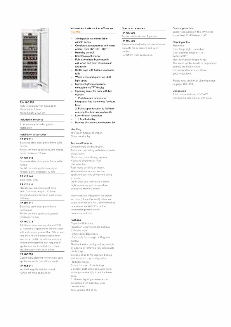
R W 466 365
Fully integrated, with glass door
Nichewidth61cm, Nicheheight213.4cm
Included in the price
1 Accessory for side-by-side
installation
Installation accessories
R A 421 611
Stainless steel door panel frame with
handle
For 61 cm wide appliances, left-hinged,
panel thickness 19 mm.
R A 421 612
Stainless steel door panel frame with
handle
For 61 cm wide appliances, right-
hinged, panel thickness 19 mm.
R A 423 140
Side trims, long.
R A 425 110
Handle bar, stainless steel, long
With 3 mounts, length 1131 mm,
drilling distance between each mount
554 mm.
R A 428 611
Stainless steel door panel frame,
handleless
For 61 cm wide appliances, panel
thickness 19 mm.
R A 460 013
Additional side heating element 230
V. Required if appliances are installed
with a distance greater than 16 mm and
less than 160 mm next to each other
and for all built-in situations in a very
humidenvironement.Notrequiredifappliances are installed more than
160 mm apart from each other.
R A 460 020
Connecting element for vertically split
appliancefronts(foraflushfront).R A 464 611
Ventilation grille stainless steel
For 61 cm wide appliances.
Vario wine climate cabinet 400 series
R W 466
— 3 independently controllable
climate zones
— Consistent temperatures with exact
control from +5 °C to +20 °C
— Humidity control
— Stainless steel interior
— Fully extendable bottle trays in
oak wood and solid aluminium in
anthracite
— Bottle trays with hidden telescopic
rails
— Warm white and glare-free LED
light spots
— 5 preset lighting scenarios,
selectable via TFT display
— Opening assist for door with two
options:
1. Push-to-open function for
integration into handleless furniture
front
2. Pull-to-open function to facilitate
opening the door using a handle
— Low-vibration operation
— TFT touch display
— Numberofstandardwinebottles:99
Handling
TFT touch display operation.
Clear text display.
Technical Features
Dynamic cold air distribution.
Automatic defrosting with defrost water
evaporation.
Cushioned door closing system.
Activatedcharcoalairfilter.UV-protection.
RestmodecertifiedbyStar-K.When rest mode is active, the
appliance can only be opened using
a handle.
Open-door and malfunction alarm.
Light scenarios and temperature
setting via Home Connect.
Home network integration for digital
services (Home Connect) either via
cableconnectionLAN(recommended)or wireless via WiFi. For further
information please check:
home-connect.com
Features
Capacity 99 bottles
(based on 0.75/l standard bottles).
12 bottle trays,
- 9 fully extendable trays
- 3 suitable for storage of Magnum
bottles.
Flexibleinteriorconfigurationpossibleby adding or removing fully extendable
bottle trays.
Storage of up to 12 Magnum bottles
withstandardtrayconfiguration (12 bottle trays).
Space for max. 12 bottle trays.
2 brilliant LED light spots with warm
white, glare-free light in each climate
zone.
5differentlightingscenarioscanbe selected for individual wine
presentation.
Total volume 361 litres.
Consumption data
Energy consumption 155 kWh/year.
Noiselevel42dB(A)re1pW.
Planning notes
Flat hinge.
Door hinge right, reversible.
Door opening angle of 115°,
fixableat90°.Max. door panel weight 73 kg.
The mains socket needs to be planned
outside the built-in niche.
Notransport/operationabove 2000 m sea level.
Please read additional planning notes
on page 160–163.
Connection
Total connected load 0.300 kW.
Connecting cable 3.0 m, with plug.
Special accessories
R A 430 000
Screw hole cover set. 8 pieces.
R A 492 660
Removable shelf with oak wood frame
Suitable for decanters and open
bottles.
For 61 cm wide appliances.
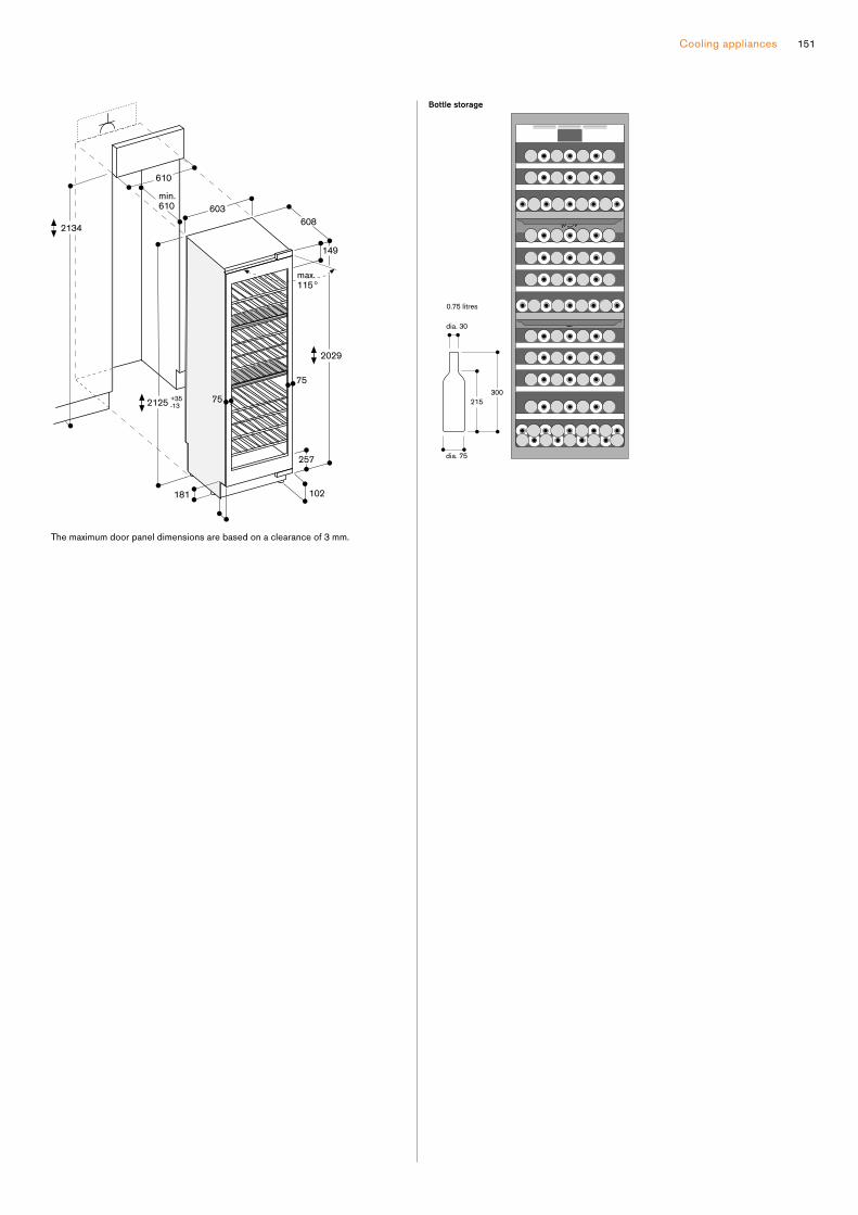
Cooling appliances 151
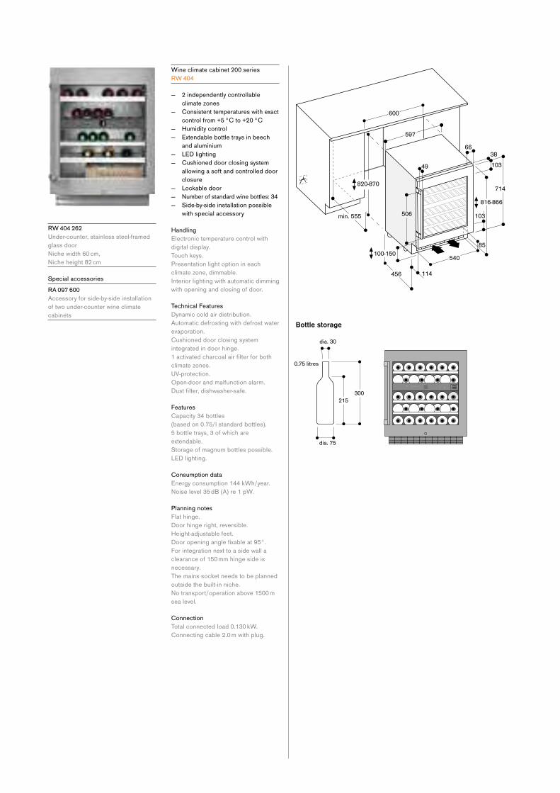
Wine climate cabinet 200 series
R W 404
— 2 independently controllable
climate zones
— Consistent temperatures with exact
control from +5 °C to +20 °C
— Humidity control
— Extendable bottle trays in beech
and aluminium
— LED lighting
— Cushioned door closing system
allowing a soft and controlled door
closure
— Lockable door
— Numberofstandardwinebottles:34 — Side-by-side installation possible
with special accessory
Handling
Electronic temperature control with
digital display.
Touch keys.
Presentation light option in each
climate zone, dimmable.
Interior lighting with automatic dimming
with opening and closing of door.
Technical Features
Dynamic cold air distribution.
Automatic defrosting with defrost water
evaporation.
Cushioned door closing system
integrated in door hinge.
1activatedcharcoalairfilterforbothclimate zones.
UV-protection.
Open-door and malfunction alarm.
Dustfilter,dishwasher-safe.
Features
Capacity 34 bottles
(based on 0.75/l standard bottles).
5 bottle trays, 3 of which are
extendable.
Storage of magnum bottles possible.
LED lighting.
Consumption data
Energy consumption 144 kWh/year.
Noiselevel35dB(A)re1pW.
Planning notes
Flat hinge.
Door hinge right, reversible.
Height-adjustable feet.
Dooropeninganglefixableat95°.For integration next to a side wall a
clearance of 150 mm hinge side is
necessary.
The mains socket needs to be planned
outside the built-in niche.
Notransport/operationabove1500msea level.
Connection
Total connected load 0.130 kW.
Connecting cable 2.0 m with plug.
R W 404 262
Under-counter, stainless steel-framed
glass door
Nichewidth60cm, Nicheheight82cm
Special accessories
R A 097 600
Accessory for side-by-side installation
of two under-counter wine climate
cabinets

Cooling appliances 153
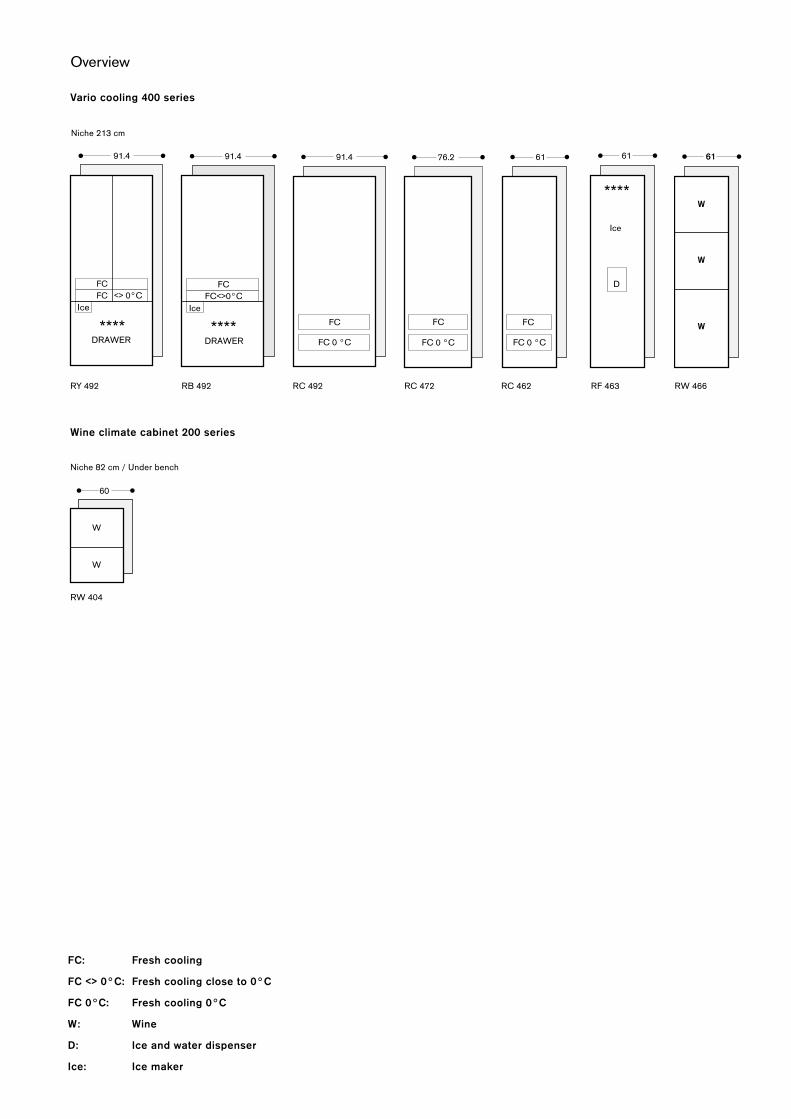
RC 462
Wine climate cabinet 200 series
Niche82cm/Underbench
RW 404
Overview
Niche213cm
RY 492 RF 463 RW 466
FC: Fresh cooling
FC <> 0°C: Fresh cooling close to 0°C
FC 0°C: Fresh cooling 0°C
W: Wine
D: Ice and water dispenser
Ice: Ice maker
Vario cooling 400 series
RC 492 RC 472RB 492
FC<>0°C

Cooling appliances 155

Planning principle for an individual appliance
Installation niche for an individual cooling appliance (example: 610 mm wide)
In this example, the installation niche is formed by two tall cupboards (left and right)
with an appropriate crown to the niche.
The cabinet door for the appliance comes in an identical design to the other kitchen
fronts.
Requirements for the installation niche:
— Thesidewallsoftheinstallationnichemustbecompletelyevenandflatalongtheir entire depth
— Crown is at least 100 mm deep and made of a solid material (min. 16 mm thick)
— Width of the installation niche: 610 mm
— Depth of the installation niche: 610 mm
Cabinet front
Cabinet
Crown
Installation nichePlinth
Wall
Worktop
Floor
Cabinet
Cabinet front
Horizontal cut Installation niche
The side walls of the installation niche must be completely
evenandflatalongtheirentiredepth.
Crown
Cabinet front
Cabinet
Vertical cut Installation niche

Cooling appliances 157
Planning principle for a side-by-side solution
Crown
Cabinet front
Cabinet
Horizontal cut Installation niche
The side walls of the installation niche must be completely
evenandflatalongtheirentiredepth.
Vertical cut Installation nicheInstallation niche for a side-by-side solution
— 610 mm cooling appliance (right)
— 610 mm freezer (left)
In this example, the installation niche is formed by a tall cupboard (left) and a stable
plinth (right) together with an appropriate crown for the niche.
The cabinet door for both appliances comes in an identical design to the other
kitchen fronts.
Requirements for the installation niche:
— Thesidewallsoftheinstallationnichemustbecompletelyevenandflatalongtheir entire depth
— Crown is at least 100 mm deep and made of a solid material (min. 16 mm thick)
— Width of the installation niche:
610 mm + 610 mm = 1.220 mm
— Depth of the installation niche: 610 mm
Crown
Installation niche Plinth
Wall
Worktop
Floor
Stable plinth
Cabinet front
Cabinet
Worktop
Wall cabinet
Stable plinth
Cabinet front
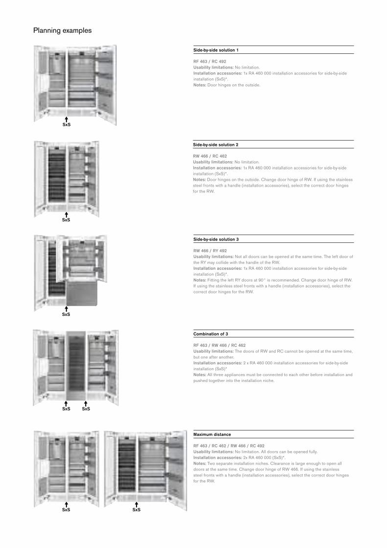
Planning examples
Side-by-side solution 1
RF 463 / RC 492
Usability limitations:Nolimitation.Installation accessories: 1x RA 460 000 installa tion accessories for side-by-side
installation (SxS)*.
Notes: Door hinges on the outside.
Side-by-side solution 2
RW 466 / RC 462
Usability limitations:Nolimitation.Installation accessories: 1x RA 460 000 installa tion accessories for side-by-side
installation (SxS)*.
Notes: Door hinges on the outside. Change door hinge of RW. If using the stainless
steel fronts with a handle (installation accessories), select the correct door hinges
for the RW.
Side-by-side solution 3
RW 466 / RY 492
Usability limitations:Notalldoorscanbeopenedatthesametime.Theleftdoorofthe RY may col lide with the handle of the RW.
Installation accessories: 1x RA 460 000 installation accessories for side-by-side
installation (SxS)*.
Notes: Fitting the left RY doors at 90° is recommended. Change door hinge of RW.
If using the stainless steel fronts with a handle (installation accessories), select the
correct door hinges for the RW.
Combination of 3
RF 463 / RW 466 / RC 462
Usability limitations: The doors of RW and RC cannot be opened at the same time,
but one after another.
Installation accessories: 2 x RA 460 000 installation accessories for side-by-side
installation (SxS)*
Notes: All three appliances must be connected to each other before installation and
pushed together into the installation niche.
Maximum distance
RF 463 / RC 462 / RW 466 / RC 492
Usability limitations:Nolimitation.Alldoorscanbeopenedfully.Installation accessories: 2x RA 460 000 (SxS)*.
Notes: Two separate installation niches. Clearance is large enough to open all
doors at the same time. Change door hinge of RW 466. If using the stainless
steel fronts with a handle (installation accessories), select the correct door hinges
for the RW.
SxS SxS
SxS
SxS
SxS
SxS
SxS

Cooling appliances 159
Footnote:
*SxS Accessory for side-by-side installation
*HE Additional side heating element
Distance ≥ 160 mm
RF 463 / RW 466 / RF 463 / RC 462
Usability limitations: The middle doors cannot be opened at the same time.
Installation accessories: 2x RA 460 000 (SxS)*.
Notes: Two separate installation niches. The clear ance between the two installation
niches is greater than 160 mm. If using the stainless steel fronts with a handle
(installation accessories), select the correct door hinges for the RW.
Distance ≤ 160 mm
RF 463 / RC 462 / RW 466 / RC 492
Usability limitations: It may be necessary to open the middle doors one after the
other, rather than at the same time.
Installation accessories: 2x RA 460 000 (SxS)*, 1x RA 460 013 (HE)*.
Notes: Two separate installation niches with a stable plinth between them. The
clearance between the two installation niches is less than 160 mm. Therefore, an
additional side heating element is required. Change door hinge of RW. If using the
stainless steel fronts with handle (installation accessories), select the correct door
hinges for the RW.
Combination of 4
RF 463 / RW 466 / RF 463 / RC 492
Usability limitations: The middle doors cannot be opened at the same time.
Installation accessories: 3x RA 460 000 installation accessories for side-by-side
installation (SxS)*.
Notes: The appliances in the middle are connected side-by-side. Connecting the
others will require additional side-by-side installation accessory. All four appliances
must be connected to each other before installation and pushed together into the
installation niche.
Combination of 4 - alternative
RF 463 / RC 462 / RW 466 / RC 462
Usability limitations: The middle doors cannot be opened at the same time.
Installation accessories: 3x RA 460 000 installation accessories for side-by-side
installation (SxS)*.
Notes: The appliances in the middle are connected hinge to hinge. All four
appliances must be connected to each other before installation and pushed
together into the installation niche. Change door hinge of RF 461 and RW 466.
If using the stainless steel fronts with handle (installation accessories), select the
correct door hinges for the RW.
SxSSxS SxS
SxS SxSSxS
SxS SxSHE
SxS SxS
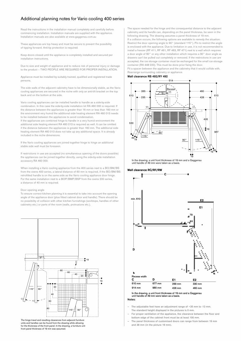
Wall clearance RC/RF/RW --------c----------
I min. 610
19
D
Recess width C D E1 610 mm 677 mm 299mm 914 mm 980mm 428mm
E2
E1
79
E2 330mm 460mm
In the drawing, a unit front thickness of 19 mm and a Gaggenau unit handle of 49 mm were taken as a basis.
Additional planning notes for Vario cooling 400 series
Read the instructions in the installation manual completely and carefully before
commencing installation. Installation manuals are supplied with the appliance.
Installation manuals are also available at www.gaggenau.com.au
These appliances are top heavy and must be secure to prevent the possibility
of tipping forward. Anti-tip protection is required.
Keep doors closed until the appliance is completely installed and secured per
installation instructions.
Due to size and weight of appliance and to reduce risk of personal injury or damage
totheproduct–TWOPEOPLEAREREQUIREDFORPROPERINSTALLATION.
Appliancemustbeinstalledbysuitablytrained,qualifiedandregisteredtradepersons.
The side walls of the adjacent cabinetry have to be dimensionally stable, as the Vario
cooling appliances are secured in the niche with only an anti-tilt bracket on the top
back and on the bottom at the side.
Vario cooling appliances can be installed handle to handle as a side-by-side
combination. In this case the side-by-side installation kit RA 460 000 is required. If
the distance between the appliances is greater than 16 mm or less than 160 mm or
the environment very humid the additional side heating element RA 460 013 needs
to be installed between the appliances to avoid condensation.
If the appliances are combined hinge to handle in a very humid environment the
additional side heating element RA 460 013 is required as well. It can be omitted
if the distance between the appliances is greater than 160 mm. The additional side
heating element RA 460 013 does not take up any additional space. It is already
included in the niche dimensions.
If the Vario cooling appliances are joined together hinge to hinge an additional
stable side wall must be foreseen.
If restrictions in use are accepted (no simultaneous opening of the doors possible)
the appliances can be joined together directly, using the side-by-side installation
accessory RA 460 000.
When installing a Vario cooling appliance from the 400 series next to a BO/BM/BS
from the ovens 400 series, a lateral distance of 60 mm is required, if the BO/BM/BS
retrofittedhandleisonthesamesideastheVariocoolingappliancedoorhinge. For the same installation next to a BOP/BMP/BSP from the ovens 200 series,
a distance of 40 mm is required.
Door opening angle
To ensure correct kitchen planning it is essential to take into account the opening
angleoftheappliancedoor(plusfittedcabinetdoorandhandle).Thereshouldbeno possibility of collision with other kitchen furnishings (worktops, handles of other
cabinetry etc.) or parts of the room (walls, protrusions etc.).
Notes:
– The adjustable feet have an adjustment range of +35 mm to -13 mm. The standard height displayed in the pictures is 0 mm.
– For proper ventilation of the appliance, the clear ance between the floor and bottom edge of the cabinet front must be at least 100 mm.
– The panel thickness of customised doors can range from between 19 mm and 38 mm (in the picture 19 mm).
The space needed for the hinge and the consequential distance to the adjacent
cabinetry and its handle can, depending on the panel thickness, be seen in the
following drawing. The drawing assumes a panel thickness of 19 mm.
If a collision occurs, the following options are available to remedy the situation:
Restrict the door opening angle to 90° (standard 115°). Pin to restrict the angle
is enclosed with the appliance. Due to limitation in use, it is not recommended to
install a freezer (RF 411, RF 461, RF 463, RF 471) next to a wall which requires
a door angle of 90° or any other installation which requires a 90° door angle as
drawers can’t be pulled out completely or removed. If the restrictions in use are
accepted, the ice storage container must be exchanged for the small ice storage
container(RA448220).Thismustbedonepriorfixingthedoor.Fit a spacer between the appliance and the cabinetry that it would collide with.
Rearrange surrounding cabinetry or appliance.
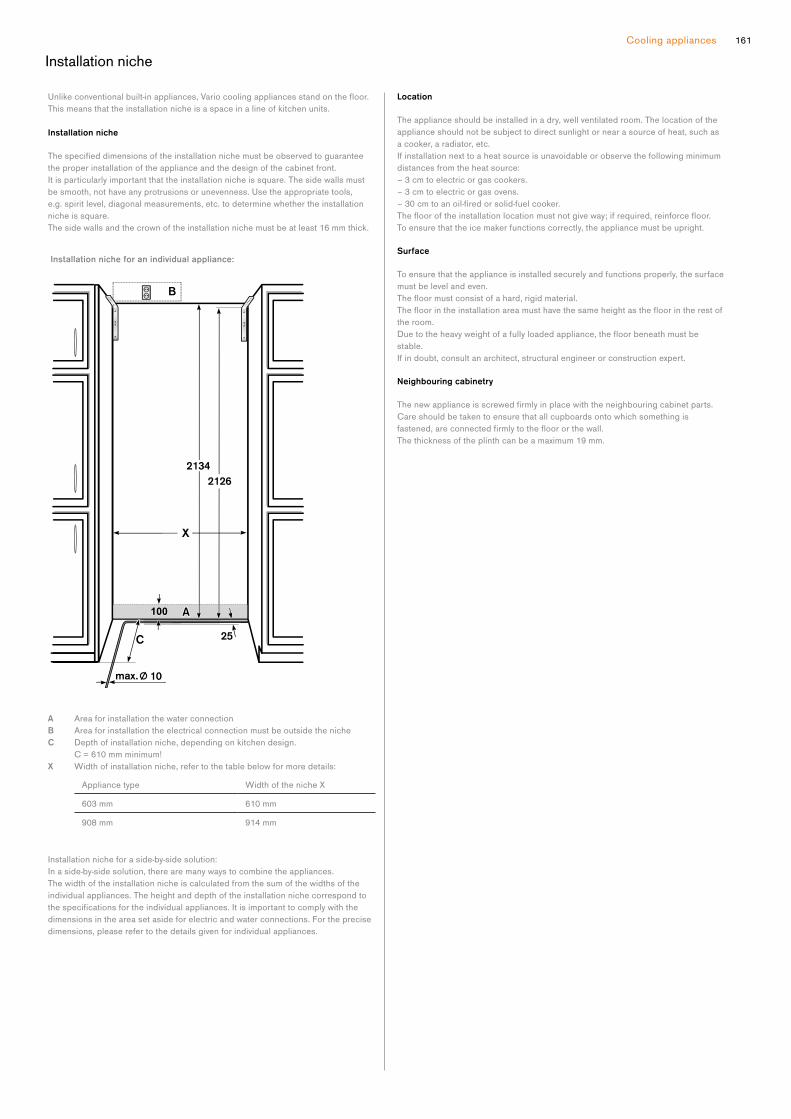
Cooling appliances 161
Location
The appliance should be installed in a dry, well ventilated room. The location of the
appliance should not be subject to direct sunlight or near a source of heat, such as
a cooker, a radiator, etc.
If installation next to a heat source is unavoidable or observe the following minimum
dis tances from the heat source:
– 3 cm to electric or gas cookers.
– 3 cm to electric or gas ovens.
–30cmtoanoil-firedorsolid-fuelcooker.Theflooroftheinstallationlocationmustnotgiveway;ifrequired,reinforcefloor. To ensure that the ice maker functions correctly, the appliance must be upright.
Surface
To ensure that the appliance is installed securely and functions properly, the surface
must be level and even.
Thefloormustconsistofahard,rigidmaterial.Thefloorintheinstallationareamusthavethesameheightasthefloorintherestofthe room.
Duetotheheavyweightofafullyloadedappliance,thefloorbeneathmustbestable.
If in doubt, consult an architect, structural engineer or construction expert.
Neighbouring cabinetry
Thenewapplianceisscrewedfirmlyinplacewiththeneighbouringcabinetparts.Care should be taken to ensure that all cupboards onto which something is
fastened,areconnectedfirmlytothefloororthewall.The thickness of the plinth can be a maximum 19 mm.
Unlikeconventionalbuilt-inappliances,Variocoolingappliancesstandonthefloor.This means that the installation niche is a space in a line of kitchen units.
Installation niche
Thespecifieddimensionsoftheinstallationnichemustbeobservedtoguaranteethe proper installa tion of the appliance and the design of the cabinet front.
It is particularly important that the installation niche is square. The side walls must
be smooth, not have any protrusions or unevenness. Use the appropriate tools,
e.g. spirit level, diagonal measurements, etc. to determine whether the installation
niche is square.
The side walls and the crown of the installation niche must be at least 16 mm thick.
A Area for installation the water connection
B Area for installation the electrical connection must be outside the niche
C Depth of installation niche, depending on kitchen design.
C = 610 mm minimum!
X Width of installation niche, refer to the table below for more details:
Appliance type WidthofthenicheX603 mm 610 mm
908 mm 914 mm
Installation niche for a side-by-side solution:
In a side-by-side solution, there are many ways to combine the appliances.
The width of the installation niche is calculated from the sum of the widths of the
individual appliances. The height and depth of the installation niche cor respond to
thespecificationsfortheindividualappliances.Itisimportanttocomplywiththedimensions in the area set aside for electric and water connections. For the precise
dimensions, please refer to the de tails given for individual appliances.
Installation niche for an individual appliance:
Installation niche
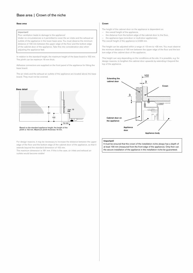
Base area | Crown of the niche
Crown
The height of the cabinet door on the appliance is dependent on:
— the overall height of the appliance,
— thedistancefromthebottomedgeofthecabinetdoortothefloor, — the appliance type (one-door or multi-door appliances).
The overall height of the appliance is 2.029 mm.
The height can be adjusted within a range of -13 mm to +35 mm. You must observe
theminimumdistanceof100mmbetweentheupperedgeofthefloorandthebot-tom edge of the cabinet door of the appliance.
This height can vary depending on the conditions at the site. It is possible, e.g. for
design reasons, to lengthen the cabinet door upwards by extending it beyond the
top of the appliance.
Important!
It must be ensured that the crown of the instal lation niche always has a depth of
at least 100 mm (measured from the front edge of the appliance). Only then can
the secure installation of the appliance in the installation niche be guaranteed.
Extending the
cabinet door
Appliance
door
Crown
Appliance body
Cabinet door on
the appliance
Base area
Important!
Poor ventilation leads to damage to the appliance!
Under no circumstances is it permitted to cover the air inlets and the exhaust air
outlets of the appli ance in the lower base area. You must observe the minimum
distanceof100mmbetweentheupperedgeofthefloorandthebottomedgeof the cabinet door of the appliance. Take this into consideration also when
adjusting the appliance feet.
In relation to the standard height, the maximum height of the base board is 102 mm.
The plinth can be maximum 19 mm thick.
Adhesiveconnectorsaresuppliedonthefrontpaneloftheapplianceforfittingthebase board.
The air inlets and the exhaust air outlets of the appliance are located above the base
board. They must not be covered.
For design reasons, it may be necessary to in crease the distance between the upper
edgeofthefloorandthebottomedgeofthecabinetdooroftheappliance,sothatitextends beyond the stan dard dimension of 102 mm.
The maximum dimen sion is 181 mm. If this is the case, air inlets and exhaust air
outlets would become visi ble!
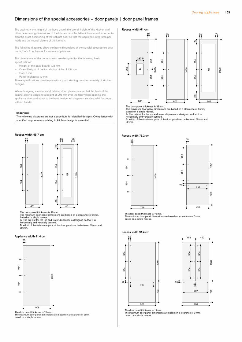
Cooling appliances 163163
Dimensions of the special accessories – door panels | door panel frames
The cabinetry, the height of the base board, the overall height of the kitchen and
other determining dimensions of the kitchen must be taken into ac count, in order to
plan the exact positioning of the cabinet door so that the appliance integrates per-
fectly into the overall picture of the kitchen.
The following diagrams show the basic dimensions of the special accessories door
fronts/door front frames for various appliances.
The dimensions of the doors shown are designed for the following basic
specifications: — Height of the base board: 102 mm
— Overall height of the installation niche: 2.134 mm
— Gap: 3 mm
— Panel thickness: 19 mm
Thesespecificationsprovideyouwithagoodstartingpointforavarietyofkitchendesigns.
When designing a customised cabinet door, please ensure that the back of the
cabinetdoorisvisibletoaheightof205mmoverthefloorwhenopeningtheappliance door and adapt to the front design. All diagrams are also valid for doors
without handle.
Important!
The following diagrams are not a substitute for detailed designs. Compliance with
specifiedrequirementsrelatingtokitchendesignisessential.
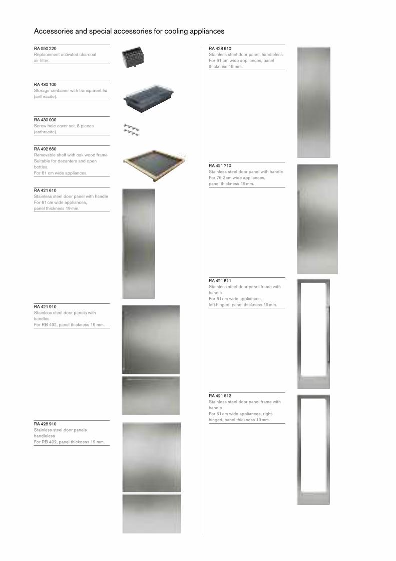
Accessories and special accessories for cooling appliances
R A 050 220
Replacement activated charcoal
airfilter.
R A 430 100
Storage container with transparent lid
(anthracite).
R A 430 000
Screw hole cover set. 8 pieces
(anthracite).
R A 492 660
Removable shelf with oak wood frame
Suitable for decanters and open
bottles.
For 61 cm wide appliances.
R A 421 610
Stainless steel door panel with handle
For 61 cm wide appliances,
panel thickness 19 mm.
RA 421 910
Stainless steel door panels with
handles
For RB 492, panel thickness 19 mm.
RA 428 910
Stainless steel door panels
handleless
For RB 492, panel thickness 19 mm.
R A 428 610
Stainless steel door panel, handleless
For 61 cm wide appliances, panel
thickness 19 mm.
R A 421 710
Stainless steel door panel with handle
For 76.2 cm wide appliances,
panel thickness 19 mm.
R A 421 611
Stainless steel door panel frame with
handle
For 61 cm wide appliances,
left-hinged, panel thickness 19 mm.
R A 421 612
Stainless steel door panel frame with
handle
For 61 cm wide appliances, right-
hinged, panel thickness 19 mm.

Cooling appliances 165
R A 421 911
Stainless steel door panel with handle
For 91.4 cm wide appliances, panel
thickness 19 mm.
R A 428 611
Stainless steel door panel frame,
handleless
For 61 cm wide appliances, panel
thickness 19 mm.
R A 421 912
Stainless steel door panels with
handles
For RY 492, panel thickness 19 mm.
R A 428 912
Stainless steel door panels, handleless
For RY 492, panel thickness 19 mm.
R A 428 911
Stainless steel door panel, handleless
For 91.4 cm wide appliances, panel
thickness 19 mm.
R A 428 710
Stainless steel door panel, handleless
For 76.2 cm wide appliances, panel
thickness 19 mm.
R A 422 610
Stainless steel door panel with handle
For RF 463,
panel thickness 19 mm.
R A 428 810
Stainless steel door panel, handless
For RF 463, panel thickness 19 mm.
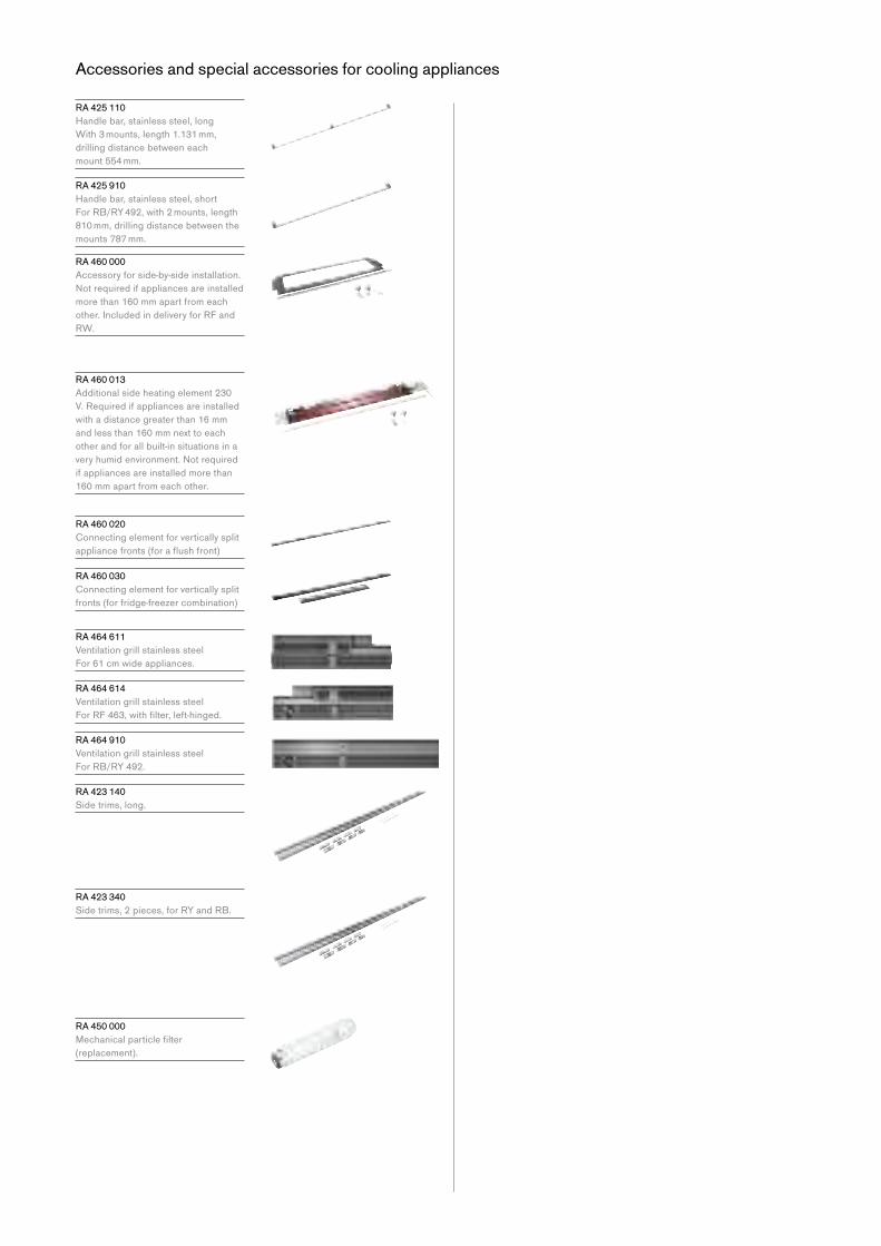
R A 425 110
Handle bar, stainless steel, long
With 3 mounts, length 1.131 mm,
drilling distance between each
mount 554 mm.
R A 425 910
Handle bar, stainless steel, short
For RB/RY 492, with 2 mounts, length
810 mm, drilling distance between the
mounts 787 mm.
R A 460 000
Accessory for side-by-side installation.
Notrequiredifappliancesareinstalledmore than 160 mm apart from each
other. Included in delivery for RF and
RW.
R A 460 013
Additional side heating element 230
V. Required if appliances are installed
with a distance greater than 16 mm
and less than 160 mm next to each
other and for all built-in situations in a
veryhumidenvironment.Notrequiredif appliances are installed more than
160 mm apart from each other.
R A 460 020
Connecting element for vertically split
appliancefronts(foraflushfront)
R A 460 030
Connecting element for vertically split
fronts (for fridge-freezer combination)
R A 464 611
Ventilation grill stainless steel
For 61 cm wide appliances.
R A 464 614
Ventilation grill stainless steel
ForRF463,withfilter,left-hinged.
R A 464 910
Ventilation grill stainless steel
For RB/RY 492.
R A 423 140
Side trims, long.
R A 423 340
Side trims, 2 pieces, for RY and RB.
R A 450 000
Mechanicalparticlefilter (replacement).
Accessories and special accessories for cooling appliances

Cooling appliances 167
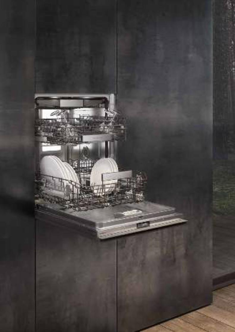

169
The dishwashers
Dishwashers 400 series 170
Dishwashers 200 series 172
Planning notes 174
Accessories | special accessories 176

Dishwasher 400 series
D F 481
— Optimal protection for sensitive
glassware by low temperature
drying with zeolite, elaborated
basket design and intelligent water
softening
— 8 programs with aqua sensor
and 4 options, such as Power
for cleaning and drying dishes in
57 minutes and Intensive for
particularly thorough cleaning in
the lower basket
— Flexible basket system with smooth
running rails on all levels and
cushioned closing of the upper
and lower basket
— Perfectly illuminated interior
— Push-to-open function for perfect
integration into handleless furniture
fronts
— Flexible hinge for reduced plinth
height as of 50 mm
— Lateral Info-Light
— Very quiet: 42 dB
Handling
TFT display indicating remaining or
endtime,refillforsaltandrinsingagent,inflowofwater.Touch key operation.
Flexible cycle time reduction, even
during an active cycle.
Drying assistant for optional door
opening at the end of the program.
Personalisation function for storing
individual combinations of programs.
Temporary noise reduction (only
available with active Home Connect
functionality).
Information key with use indicators.
Time delay up to 24 hours.
Visual and acoustic end of program
indicator.
Lateral Info-Light.
Technical Features
Perfectly illuminated interior.
Glass protection with zeolite.
Aqua sensor.
Load sensor.
Detergent recognition.
Regeneration electronics.
Heat exchanger.
Continuousflowheater.Triplefiltersystem.Soft lock.
Aqua stop.
Home network integration for digital
services (Home Connect) either via
cableconnectionLAN(recommended)or wireless via WiFi. For further
information please check:
home-connect.com
Programs
8 programs:
Auto 35 °C - 45 °C.
Auto 45 °C - 65 °C.
Auto 65 °C - 75 °C.
Intensive 70 °C.
Eco 50 °C.
Nightprogram.
Quick wash 45 °C (29 min.).
Personalisation function
(default setting: Pre-rinse).
4 options:
Intensive.
Power.
Half Load.
Hygiene.
Machine Care.
Features
Flexible basket system with smooth
running rails on all levels and
cushioned closing of the upper and
lower basket.
Upper basket:
Over extension.
Optional extra cleaning area by
activating additional spray nozzles.
Rackmatic with 3 levels, adjustable in
height up to 5 cm.
6 folding spines.
4 folding racks for optimal protection
of glass.
Lower basket:
8 folding spines.
2 folding racks for optimal protection
of glass.
Dividable glass support.
Cutlery basket.
Maximum dish sizes
(upper/lower basket)
for 86.5 cm high dishwashers:
29/28, 26.5/30.5 or 24/34 cm
respectively.
14 place setting capacity.
Maximum glass loading capacity
23 wine glasses.
Consumption data
4 star energy rating with
230 kWh per year
5 star WELS water rating with 11.5
litres per wash
Noiselevel42dB(re1pW).
Planning notes
Height-adjustable feet.
Appliance plinth recess 100 mm
(see drawing).
Rear feet adjustable at front.
Door weight up to 11 kg.
Door panel dimension dependent on
plinth height of kitchen furniture.
Installation and usage also with
furniture handle possible. The push-to-
open function remains active.
Please read additional planning notes,
alsoconcerningflexiblehinge,onpage 174–175.
Connection
Total connected load 2000-2400 W.
Connecting cable with plug.
Water connection with 3/4“ screw
joint.
Connection to hot or cold water
possible.
D F 481 500 F
Fully integrated
Height 86.5 cm
Withflexiblehinge
Included in the price
1 baking tray spray head
2 GNcontainerinserts1 holder for long-stemmed glasses
1 stainless steel trim kit
Special accessories
D A 045 061
3rd basket
With smooth running rails
For 86.5 cm high dishwashers
3rd loading level above the upper
basket.
For small bowls, cups and cooking
utensiles.
Movable knife shelf.

171Dishwashers
max. 220
min. 50-
min.
550
86.5 cm high dishwasher with flexible hinge
53
100
89
598
600
550
865-
925
865-925
705-
815
16-22
( ) values with extension kit
1.2 m (3.4 m)
1.5 m (3.5 m)(3.7 m) 1.7 m
(3.7 m) 1.5 m
1.6 m1.2 m
Connection dimensions for a 60 cm wide dishwasher
60
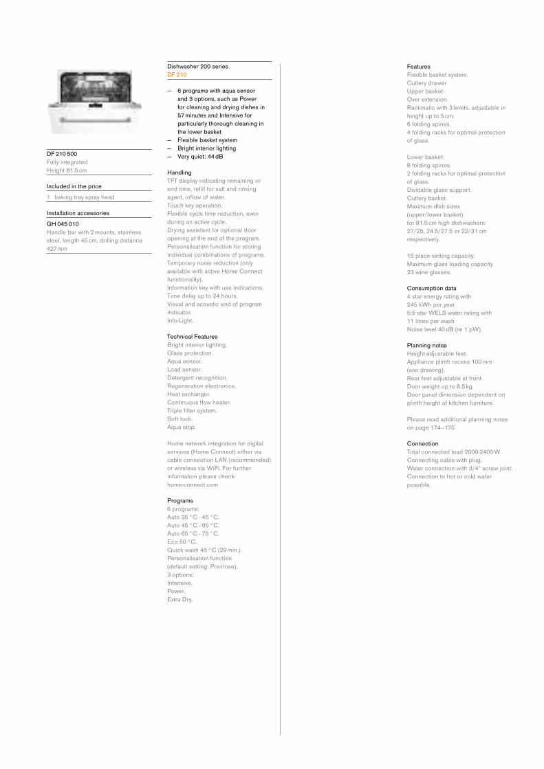
D F 210 500
Fully integrated
Height 81.5 cm
Included in the price
1 baking tray spray head
Installation accessories
G H 045 010
Handle bar with 2 mounts, stainless
steel, length 45 cm, drilling distance
427 mm
Dishwasher 200 series
D F 210
— 6 programs with aqua sensor
and 3 options, such as Power
for cleaning and drying dishes in
57 minutes and Intensive for
particularly thorough cleaning in
the lower basket
— Flexible basket system
— Bright interior lighting
— Very quiet: 44 dB
Handling
TFT display indicating remaining or
endtime,refillforsaltandrinsingagent,inflowofwater.Touch key operation.
Flexible cycle time reduction, even
during an active cycle.
Drying assistant for optional door
opening at the end of the program.
Personalisation function for storing
individual combinations of programs.
Temporary noise reduction (only
available with active Home Connect
functionality).
Information key with use indications.
Time delay up to 24 hours.
Visual and acoustic end of program
indicator.
Info-Light.
Technical Features
Bright interior lighting.
Glass protection.
Aqua sensor.
Load sensor.
Detergent recognition.
Regeneration electronics.
Heat exchanger.
Continuousflowheater.Triplefiltersystem.Soft lock.
Aqua stop.
Home network integration for digital
services (Home Connect) either via
cableconnectionLAN(recommended)or wireless via WiFi. For further
information please check:
home-connect.com
Programs
6 programs:
Auto 35 °C - 45 °C.
Auto 45 °C - 65 °C.
Auto 65 °C - 75 °C.
Eco 50 °C.
Quick wash 45 °C (29 min.).
Personalisation function
(default setting: Pre-rinse).
3 options:
Intensive.
Power.
Extra Dry.
Features
Flexible basket system.
Cutlery drawer
Upper basket:
Over extension.
Rackmatic with 3 levels, adjustable in
height up to 5 cm.
6 folding spines.
4 folding racks for optimal protection
of glass.
Lower basket:
8 folding spines.
2 folding racks for optimal protection
of glass.
Dividable glass support.
Cutlery basket.
Maximum dish sizes
(upper/lower basket)
for 81.5 cm high dishwashers:
27/25, 24.5/27.5 or 22/31 cm
respectively.
15 place setting capacity.
Maximum glass loading capacity
23 wine glasses.
Consumption data
4 star energy rating with
245 kWh per year
5.5 star WELS water rating with
11 litres per wash
Noiselevel40dB(re1pW).
Planning notes
Height-adjustable feet.
Appliance plinth recess 100 mm
(see drawing).
Rear feet adjustable at front.
Door weight up to 8.5 kg.
Door panel dimension dependent on
plinth height of kitchen furniture.
Please read additional planning notes
on page 174–175
Connection
Total connected load 2000-2400 W.
Connecting cable with plug.
Water connection with 3/4” screw joint.
Connection to hot or cold water
possible.
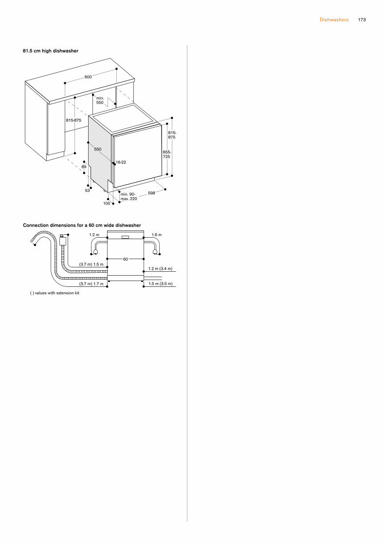
Dishwashers 173
( ) values with extension kit
1.2 m (3.4 m)
1.5 m (3.5 m)(3.7 m) 1.7 m
(3.7 m) 1.5 m
1.6 m1.2 m
Connection dimensions for a 60 cm wide dishwasher
60
815-
875
min. 90-
max. 220
min.
550
815-875
81.5 cm high dishwasher
655-
725
16-22
53
100
89
598
600
550

Additional planning notes for standard dishwashers (without flexible hinge)
For niche heights from 815 to
855 mm, in most cases, the 81.5 cm
high dishwasher must be planned,
regardless of the plinth height.
If the niche height amounts to 865 or
875 mm, please note:
Whether the 81.5 cm high dishwasher
can be used here depends on the
plinth height.
For dishwasher with remaining time
projection, the maximum plinth height
must be reduced by 30 mm to provide
an optimal display.
Cabinet height 655–725 mm
Cabinet height 705–775 mm
Nicheheightinmm→815 825 835 845 855 865 875
←Plinthheigh
tinmm
<90
90 (D) (D)
100 (D) 110 (D) 120 (D) 130 (D) 140 (D)
150 160 170 180 190 200 210 220
= 81.5 cm high dishwasher DF 210
(D)=specialsolutionwith10mmgapfromtheworktop→Spacerbatten/childlocknotpossible

Dishwashers 175
Additional planning notes for dishwashers with flexible hinge
If the installation of a dishwasher
withflexiblehingeisnecessaryornotdepends on several factors.
The door panels cannot be used with
dishwasherswithflexiblehinge.
For niche heights from 880 to
925 mm, in most cases, the 86.5 cm
high dishwasher must be planned,
regardless of the plinth height.
If the niche height amounts between
865 and 875 mm, please note:
Whether the 86.5 cm high dishwasher
can be used here depends on the
plinth height.
Front height 655–765 mm
Front height 705–815 mm
Nicheheightinmm→865 870 875 880 885 890 895 900 905 910 915 920 925
← P
linth
he
igh
t in
mm
50
55
60
65
70
75
80
85
90
95
100
105
110
115
120
125
130
135
140
145
150
155
160
165
170
175
180
185
190
195
200
205
210
215
220
= 86.5 cmhighdishwasherwithflexiblehingeDF 481 500 F
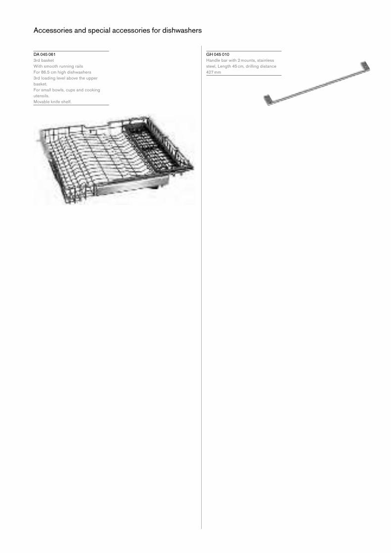
Accessories and special accessories for dishwashers
G H 045 010
Handle bar with 2 mounts, stainless
steel, Length 45 cm, drilling distance
427 mm
D A 045 061
3rd basket
With smooth running rails
For 86.5 cm high dishwashers
3rd loading level above the upper
basket.
For small bowls, cups and cooking
utensils.
Movable knife shelf.

Dishwashers 177

Thedifferenceis Gaggenau.
The information for all products is current as at the date of
publication. Whilst every care has been taken in the preparation
of this publication, BSH does not warrant the accuracy or
completeness of the information in this publication and BSH
reservestherighttoalterspecificationsandpricingwithoutnotice. To the extent permitted by law, BSH excludes all liability,
including negligence, for any loss incurred in reliance on
the contents of this publication. Please note that the appearance
and/or inclusions of products may change from those displayed
in these materials. The appliances are for household use only.
Produced in Australia. KRD 05/2021 – BH 5245 G
Gaggenau is proudly manufactured and distributed by
BSH Home Appliances Pty Ltd.
For your Gaggenau enquiry please call 1300 170 552
or visit www.gaggenau.com.au
Gaggenau Melbourne
192-196 Coventry Street
South Melbourne
Victoria 3205
+61 3 8551 1399
Related Documents