Abstract. The three phase induction machine is used in the mainly part of the industry and it requires reactive power from the grid to start and function. The reactive power consumption is economically fined so the industries install capacitors in parallel with the motors and loads. The bank capacitor, gives this reactive power to the machine in order to improve the cos φ factor in the installation. When a fault appears in the grid, this machine gives the active power to the fault, but when the overcurrent relay sets the fault, the induction machine is already with inertia with electromagnetic and mechanic specific parameters that originate a non-controlled islanding mode and it provides the power to the loads on this feeder. Even though several works are published within the islanding detection, the islanding operation about the induction machine as a generator in power wind energy applications, nevertheless in the following we show the motor perspective. The stability of the system in the time period between the relay opening and the fast reconnection is out of control, so a complete study a about the electric magnitudes, voltage and reactive power , active power and frequency and the angle stability is needed. In this paper we show a real case that appears in a distribution Medium Voltage (MV) radial network in Spain in a 25 kV feeder and we summarize the voltage /current wave form and the frequency oscillation. Key words Power Quality, distributed generation, electrical transients, islanding mode, induction machine, non-synchronism situation. 1. Introduction The electrical distribution operators (DO) are responsible of power systems operation in order to guarantee the stability of the electrical system. When there’s a source in a distribution feeder injecting current into the system like distributed generation (DG), the DO have to be aware of the electrical parameters and loads of the system in steady state and it has to manage it. The issue appears when an electrical load, transiently becomes a generator and it is non-controlled. The nature of the problem is twofold: on one hand, during the island, there’s an unbalanced three phase system, so the loads in this feeder are being fed with a high variable tension wave with the angle and amplitude out of control and on second hand, when the relay closes the circuit there’s an out of synchronism reconnection that generates a short-circuit with a high overcurrent. The growing interest in power quality (PQ), a topic of great importance for future smart grids, GD, that the DO install monitoring tools in order to detect disturbance sources and to control the network. A complete analysis of all disturbances is showed in [1]. In the power generation sources, electrical parameters are specified and regulated by the normative, but in this paper is shown a different type of disturbance that has no regulation. Our contribution is basically study a real case of islanding situation in an electrical MV distribution network, analyse the phenomena in order to search a solution to this situation. Thus, the study of this electrical transient is made in the point of common coupling (PCC) between the DO and the industry and viewed from the electrical network, because the large industry parameters of the machine are unknown. International Conference on Renewable Energies and Power Quality (ICREPQ’17) Malaga (Spain), 4 th to 6 th April, 2017 Renewable Energy and Power Quality Journal (RE&PQJ) ISSN 2172-038 X, No.15 April 2017 The influence of the self-excited induction machine into the electrical grid under instability situation - Real case measurement R. Bosch 1 , P. Casals 1 and A. Serrano 1, 2 1 Department of Electrical Engineering E.T.S.E.I.B, Polytechnic University of Catalonia Diagonal Av. – 647, 0828 Barcelona (Spain) 2 Electrica Serosense Distribuidora Pol. Ind. Panamà. Ctra. Nac. II Km. 450, 25110 Torres de Segre (Spain) https://doi.org/10.24084/repqj15.280 233 RE&PQJ, Vol.1, No.15, April 2017

Welcome message from author
This document is posted to help you gain knowledge. Please leave a comment to let me know what you think about it! Share it to your friends and learn new things together.
Transcript
Abstract. The three phase induction machine is used in the
mainly part of the industry and it requires reactive power from
the grid to start and function. The reactive power consumption
is economically fined so the industries install capacitors in
parallel with the motors and loads. The bank capacitor, gives
this reactive power to the machine in order to improve the cos
φ factor in the installation. When a fault appears in the grid, this
machine gives the active power to the fault, but when the
overcurrent relay sets the fault, the induction machine is already
with inertia with electromagnetic and mechanic specific
parameters that originate a non-controlled islanding mode and
it provides the power to the loads on this feeder. Even though
several works are published within the islanding detection, the
islanding operation about the induction machine as a generator
in power wind energy applications, nevertheless in the
following we show the motor perspective. The stability of the
system in the time period between the relay opening and the fast
reconnection is out of control, so a complete study a about the
electric magnitudes, voltage and reactive power , active power
and frequency and the angle stability is needed. In this paper
we show a real case that appears in a distribution Medium
Voltage (MV) radial network in Spain in a 25 kV feeder and we
summarize the voltage /current wave form and the frequency
oscillation.
Key words
Power Quality, distributed generation, electrical transients,
islanding mode, induction machine, non-synchronism situation.
1. Introduction
The electrical distribution operators (DO) are responsible of
power systems operation in order to guarantee the stability of
the electrical system.
When there’s a source in a distribution feeder injecting current
into the system like distributed generation (DG), the DO have
to be aware of the electrical parameters and loads of the system
in steady state and it has to manage it.
The issue appears when an electrical load, transiently becomes
a generator and it is non-controlled.
The nature of the problem is twofold: on one hand, during the
island, there’s an unbalanced three phase system, so the loads
in this feeder are being fed with a high variable tension wave
with the angle and amplitude out of control and on second hand,
when the relay closes the circuit there’s an out of synchronism
reconnection that generates a short-circuit with a high
overcurrent.
The growing interest in power quality (PQ), a topic of great
importance for future smart grids, GD, that the DO install
monitoring tools in order to detect disturbance sources and to
control the network. A complete analysis of all disturbances is
showed in [1].
In the power generation sources, electrical parameters are
specified and regulated by the normative, but in this paper is
shown a different type of disturbance that has no regulation.
Our contribution is basically study a real case of islanding
situation in an electrical MV distribution network, analyse the
phenomena in order to search a solution to this situation.
Thus, the study of this electrical transient is made in the point
of common coupling (PCC) between the DO and the industry
and viewed from the electrical network, because the large
industry parameters of the machine are unknown.
International Conference on Renewable Energies and Power Quality (ICREPQ’17)
Malaga (Spain), 4th to 6th April, 2017 Renewable Energy and Power Quality Journal (RE&PQJ)
ISSN 2172-038 X, No.15 April 2017
The influence of the self-excited induction machine into the electrical grid
under instability situation - Real case measurement
R. Bosch1, P. Casals1 and A. Serrano1, 2
1 Department of Electrical Engineering
E.T.S.E.I.B, Polytechnic University of Catalonia
Diagonal Av. – 647, 0828 Barcelona (Spain)
2 Electrica Serosense Distribuidora
Pol. Ind. Panamà. Ctra. Nac. II Km. 450, 25110 Torres de Segre (Spain)
https://doi.org/10.24084/repqj15.280 233 RE&PQJ, Vol.1, No.15, April 2017

The previous work was based on location the disturbance
source, in a big feeder with large industries and with PV
generation presence.
In Fig. 7 is shown the case of study which is formed by two MV
feeders, measuring the faults in the PCC1, and measuring the
islanding mode in the PCC2.
There are many different methods to detect islanding
phenomena in power systems, as for example [2] and [3].
The protection relay and the stability system in islanding
situation has been studied by many authors, as for example in
[4] and [5].
It can be affirmed that the stability of the system is twofold, on
the on hand Reactive Power and Voltage (QV) and in the other
hand Active Power and Frequency (Pf) [6], [7] .
In the following, we study all the process due to the transient
behaviour of the induction machine viewed from the network.
The events showed in this paper were recorded with a different
power quality analysers; Elspec PQ Box in the PCC2 and from
a PQ function of the substation protection relay, Ekor RPS
made by Ormazabal and powered by Ingeteam in PCC1.
2. Mathematical model of the self-excited
induction machine in the abc-reference frame
A. The mathematical model
The general model of the induction machine is given in (1) and
(2) by the following differential equations for the stator and the
rotor voltages:
v = r·i + dλ
dt (1)
dv
dt= -
1
C· i (2)
The matrix expression of (1) is showed in (3):
[vs
v'r] = [
rs 0
0 r'r] [
isi'r
] +d
dt[λs
λ'r] (3)
The matrix expression of (2) is showed in (4):
d
dt[vs] = -
1
C[is] (4)
In the abc-reference frame, the matrix of the stator and rotor
resistances are given by:
rs = [
ras 0 0
0 rbs 0
0 0 rcs
] (5)
r'r = [
r'ar 0 0
0 r'br 0
0 0 r'cr
] (6)
The flux linkages for the stator and rotor winding can be
expressed as:
[λs
λ'r] = [
Lss L'sr
L'rs L'rr] [
isi'r
] (7)
Finally the matrices for the winding inductances are defined
as:
Lss =
[ Lls+Lms -
1
2Lms -
1
2Lms
-1
2Lms Lls+Lms -
1
2Lms
-1
2Lms -
1
2Lms Lls+Lms]
(8)
L'rr =
[ L'lr+Lmr -
1
2L'mr -
1
2L'mr
-1
2L'mr L'lr+Lmr -
1
2L'mr
-1
2L'mr -
1
2L'mr L'lr+Lmr]
(9)
L'sr=Lms
[ Cos (θr) Cos (θr+
2π
3) Cos (θr-
2π
3)
Cos (θr-2π
3) Cos (θr) Cos (θr+
2π
3)
Cos (θr+2π
3) Cos (θr-
2π
3) Cos (θr) ]
(10)
L'rs=Lms
[ Cos (𝜃𝑟) Cos (𝜃𝑟-
2π
3) Cos (𝜃𝑟+
2π
3)
Cos (𝜃𝑟+2π
3) Cos (𝜃𝑟) Cos (𝜃𝑟-
2π
3)
Cos (𝜃𝑟-2π
3) Cos (𝜃𝑟+
2π
3) Cos (𝜃𝑟) ]
(11)
Thus, the relation of the self-inductances matrix is showed in
(12):
https://doi.org/10.24084/repqj15.280 234 RE&PQJ, Vol.1, No.15, April 2017
L'sr(θr)=[L'rs
(θr)]T
(12) Where θr is the angle rotor, Lls is the stator winding leakage
inductance per phase L’lr the rotor winding leakage inductance
per phase, Lms is the self-inductance for the stator winding ,
the Lmr is the the self-inductance for the rotor winding.
The superscript ‘denotes magnitudes that are referred to the
rotor.
The electromagnetic torque of the induction machine is given
by the expression:
Tem (t) = isT
d
dθr[L'sr][i′r] (13)
Where is represents the space vector stator currents in abc
reference and the i’r the space vector rotor currents in abc
reference.
The mechanic equations referred to the classical dynamics
theory are given by:
Tem – Tl = J dωm
dt (14)
ωm = dθm
dt (15)
Where Tl is the load torque, J the inertia moment of the rotor
and mechanic load expressed in kgr·m2.The inertia constant H
of the machine is given in (16):
H=1
2·
J·ω2
s·p2 (16)
The slip in the induction machine is calculated as in (17):
dS
dt=
Tem – Tl
tm (17)
When tm is a mechanical time constant.
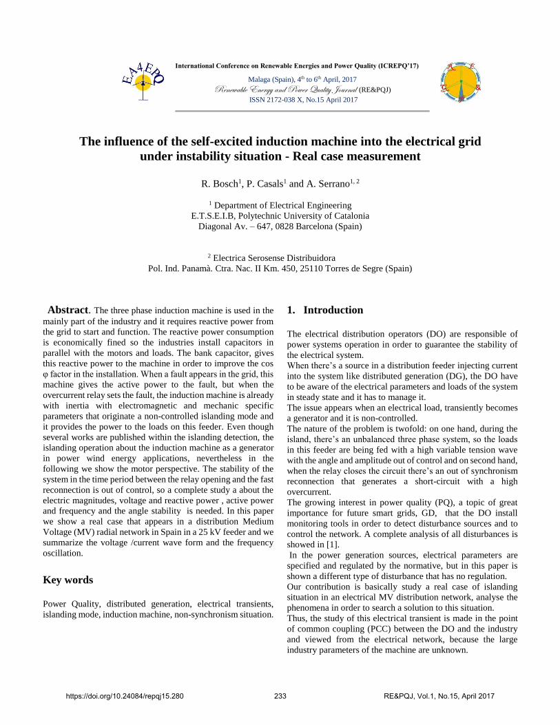
In the fig 1. is shown the model of the self-excited induction
motor in the abc reference-frame.
Figure 1.Self-excited Induction motor in the abc-reference frame.
B. Model of the system grid-load
The model of the self-excited induction machine integrated in
an electrical utility is showed in Fig.2:
Figure 2.Equivalent circuit of the large industry with the Induction
machine
3. Operation Time Sequences
Behavioural effects of the induction machine into the electrical
grid, are analysed from the beginning, starting with a pre-fault
situation in steady state, the faulted system, the islanding
situation and finally the out of phase reconnection.
A. Steady state, short circuit and breaker opening
The load flow in steady state is calculated by PSS-SINCAL
[13].
https://doi.org/10.24084/repqj15.280 235 RE&PQJ, Vol.1, No.15, April 2017

Initially the motor in PCC2 is receiving the instantaneous active
power P (t) from the grid and the instantaneous reactive power
Q (t) from the capacitor bank.
In the Fig.3 and fig.4 is showed the pre-fault situation:
Prefault Fault
Prefault Fault
Figure 3. The frequency, and the voltage/current wave at PCC1
As can be seen in the fig.3 an L-G short circuit appears in the
feeder 1 and the overcurrent protection set the fault within 60
ms. We appreciate that the current value, at steady-state, go
down from 44 A to 26 A due to the overcurrent relay aperture.
J.C.Das analysed this situation in [8].
The duration of the short circuit produces a voltage sag in one
phase, as we known is type B [9] see Fig. 2.
Prefault Fault
Prefault Fault
Figure 4. The frequency, and the voltage/current wave at PCC2
The duration of the fault is 60 ms.
We observe that after the breaker opening, the islanding
phenomena appears, thereby, the frequency goes down because
the dωm
dt is decreasing.
When the fault is set, the induction motor reaccelerates [10] .
B. Islanding situation
The islanding developed by the induction motors is absolutely
non-controlled, so because of that we have disturbances on the
frequency value and in the voltage and current wave.
https://doi.org/10.24084/repqj15.280 236 RE&PQJ, Vol.1, No.15, April 2017
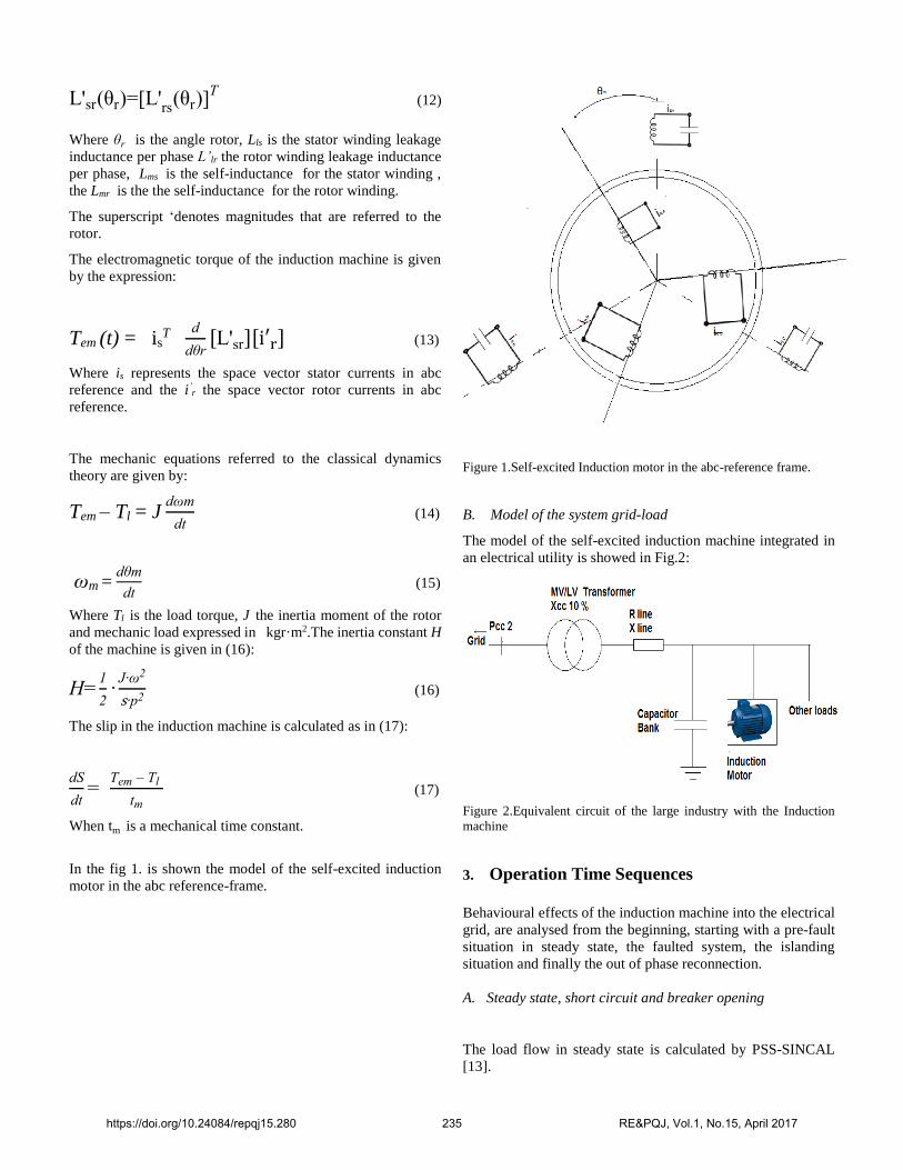
On the one hand the induction motor supply the voltage wave
amplitude but the angle is unstable, so the reference QV is not
enough to supply the reactive power to system loads.
On the other hand, the reference Pf, due to the angular velocity
decreases is either unstable, so it couldn’t supply active power
to system loads.
In the fig.4 is showed the islanding situation in the PCC2.
Figure 5. The frequency, and the voltage/current wave at PCC2
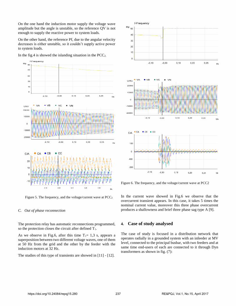
C. Out of phase reconnection
The protection relay has automatic reconnections programmed,
so the protection closes the circuit after defined T1.
As we observe in Fig.6, after this time T1= 1,3 s, appears a
superposition between two different voltage waves, one of them
at 50 Hz from the grid and the other by the feeder with the
induction motors at 32 Hz.
The studies of this type of transients are showed in [11] - [12].
Figure 6. The frequency, and the voltage/current wave at PCC2
In the current wave showed in Fig.6 we observe that the
overcurrent transient appears. In this case, it takes 5 times the
nominal current value, moreover this three phase overcurrent
produces a shallowness and brief three phase sag type A [9].
4. Case of study analysed
The case of study is focused in a distribution network that
operates radially in a grounded system with an infeeder at MV
level, connected to the principal busbar, with two feeders and at
same time end-users of each are connected to it through Dyn
transformers as shown in fig. (7):
https://doi.org/10.24084/repqj15.280 237 RE&PQJ, Vol.1, No.15, April 2017
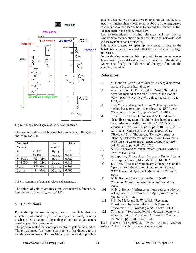
Figure 7. Single line diagram of the network analysed.
The nominal values and the essential parameters of the grid are
shown in Table 1:
Nominal
Values
Line
values
Ω/km
U 25 kV RLA 30 1,07
f 50 Hz XLA 30 0,441
Scc PCC2 85 Mva RLA 56 0,687
Scc PCC2 80 Mva XLA 56 0.416
Sfeeder 1 1,5 Mva RLA 110 0.306
Sfeeder 2 2 Mva XLA 110 0.405
Table 1. Summary of nominal values and parameters
The values of voltage are measured with neutral reference, so
that the max value is Umax= 20, 4 kV.
5. Conclusions
By analysing the oscillography, we can conclude that the
induction motor loads in presence of capacitors, surely develop
a self-excited situation so depending on its inertia parameters
could appear this phenomena.
This paper revealed that a new perspective regulation is needed.
The programmed fast reconnection time affect directly to the
transient overcurrent. To provide a solution to this problem
once is detected, we propose two options, on the one hand to
install a synchronism check relay at PCC of the aggregated
costumer and on the second hand to prolong the time of the first
reconnection in the overcurrent relay.
The aforementioned islanding situation and the out of
synchronism reconnection damage the electrical network loads
and its switchgear and protection.
This article pretend to open up new research line to the
distribution electrical networks that has the presence of large
industries.
Future developments on this topic will focus on parameter
determination, a model validation by simulation of the stability
system and finally the influence of the type fault on the
islanding situation.
References
[1] M. Donsión, Pérez, La calidad de la energia eléctrica.
Garceta Grupo Editorial, 2016.
[2] A. R. Di Fazio, G. Fusco, and M. Russo, “Islanding
detection method based on a Thevenin-like model,”
IET Gener. Transm. Distrib., vol. 9, no. 13, pp. 1747–
1754, 2015.
[3] F. Ji, Y. Li, J. Xiang, and S. Liu, “Islanding detection
method based on system identification,” IET Power
Electron., vol. 9, no. 10, pp. 2095–2102, 2016.
[4] S. Li, K. El-Arroudi, G. Joós, and A. J. Rodolakis,
“Islanding protection of multiple distributed resources
under adverse islanding conditions,” IET Gener.
Transm. Distrib., vol. 10, no. 8, pp. 1901–1912, 2016.
[5] R. Anne, F. Katha Basha, R. Palaniappan, K. L.
Oliver, and M. J. Thompson, “Reliable Generator
Islanding Detection for Industrial Power Consumers
With On-Site Generation,” IEEE Trans. Ind. Appl.,
vol. 52, no. 1, pp. 668–676, 2016.
[6] A. R. Bergen and V. Vittal, Power Systems Analysis.
Prentice Hall, 2000.
[7] A. Exposito, Gómez, Análisis y operación de sistemas
de energia eléctrica, Mac. McGraw-Hill,2002.
[8] J. C. Das, “Effects of Momentary Voltage Dips on the
Operation of Induction and Synchronous Motors,”
IEEE Trans. Ind. Appl., vol. 26, no. 4, pp. 711–718,
1990.
[9] M. H. Bollen, Understanding Power Quality
Problems: Voltage Sags and Interruptions. Wiley,
2000.
[10] M. H. J. Bollen, “Influence of motor reacceleration on
voltage sags,” IEEE Trans. Ind. Appl., vol. 31, no. 4,
pp. 667–674, 1995.
[11] F. P. De Mello and G. W. Walsh, “Reclosing
Transients in Induction Motors with Terminal
Capacitors,” AIEE Rotating Mach. Comm., 1961.
[12] C. Wagner, “Self-excitation of induction motors with
series capacitors,” Trans. Am. Inst. Electr. Eng., vol.
60, no. 12, pp. 1241–1247, 1941.
[13] Siemens PSS-SINCAL “Power systems analysis
Software” Available: https://www.siemens.com
https://doi.org/10.24084/repqj15.280 238 RE&PQJ, Vol.1, No.15, April 2017
Related Documents