Desalination 203 (2007) 141–152 Presented at EuroMed 2006 conference on Desalination Strategies in South Mediterranean Countries: Cooperation between Mediterranean Countries of Europe and the Southern Rim of the Mediterranean. Sponsored by the European Desalination Society and the University of Montpellier II, Montpellier, France, 21–25 May 2006. *Corresponding author. The El Coloso (Chile) reverse osmosis plant Marc Petry*, Miguel Angel Sanz, Chrystelle Langlais, Véronique Bonnelye, Jean-Pierre Durand, Daniel Guevara, Walter Mantovani Nardes, Cintia Homma Saemi Degremont, 183 avenue du 18 juin 1940, 92508 Rueil-Malmaison, France Tel. +33 (1) 4625 6713; Fax +33 (1) 4625 6832; email: [email protected] Received 2 May 2006; accepted 10 May 2006 Abstract Degrémont was awarded in 2004 the construction of a 45,360 m 3 /d reverse osmosis desalination plant for Minera Escondida Limitada (MEL). This plant is part of its Sulphide Leach Project which aims at increasing its production. The new plant is located on the North Coast of Chile at MEL facilities of Coloso Port, 15 km south of Antofagasta city. The desalinated water produced on site will then be pumped to the second largest open-pit copper mine in the world, 170 km away from the coast and up to an altitude of 3200 m above the sea level. This desalination plant will be the largest one in South America. The treatment line includes one of the most complete and efficient pre-treatments including grit removal, high rate dissolved air flotation (AquaDAF TM ), two stages of pressurized dual-media filtration and cartridge filters (5 μm nominal cut-off). This complete pre-treatment line has been required since the water quality of the North Coast of Chile could suffer, all-year round, from high algae and TOC concentrations. The poorest water quality has been observed during “red-tides” events (red algae bloom). This design has been confirmed by lab-scale tests performed on-site in 2004 and by the feedback of two small SWRO plants providing water for two thermal plants in the same area (Mejillones and Atacama). The pre-treatment of these two SWRO plants is a combination of a conventional DAF followed by a single stage/single media filtration. It gives satisfying results concerning clarification, nevertheless it could not maintain, most of the time, a SDI below 3%/min highlighting the necessity of an even more complete pre-treatment line as it had been anticipated. The reverse osmosis stage will be operated at a high recovery rate of 50%. It consists of a single pass with 4 trains of 137 pressure vessels each. Pressure vessels are filled with 7 FilmTec seawater 8″ elements but a special membrane doi:10.1016/j.desal.2006.05.007 0011-9164/07/$– See front matter © 2007 Published by Elsevier B.V.

Welcome message from author
This document is posted to help you gain knowledge. Please leave a comment to let me know what you think about it! Share it to your friends and learn new things together.
Transcript

Desalination 203 (2007) 141–152
Presented at EuroMed 2006 conference on Desalination Strategies in South Mediterranean Countries: Cooperationbetween Mediterranean Countries of Europe and the Southern Rim of the Mediterranean. Sponsored by theEuropean Desalination Society and the University of Montpellier II, Montpellier, France, 21–25 May 2006.
*Corresponding author.
The El Coloso (Chile) reverse osmosis plant
Marc Petry*, Miguel Angel Sanz, Chrystelle Langlais, Véronique Bonnelye,Jean-Pierre Durand, Daniel Guevara, Walter Mantovani Nardes,
Cintia Homma SaemiDegremont, 183 avenue du 18 juin 1940, 92508 Rueil-Malmaison, France
Tel. +33 (1) 4625 6713; Fax +33 (1) 4625 6832; email: [email protected]
Received 2 May 2006; accepted 10 May 2006
Abstract
Degrémont was awarded in 2004 the construction of a 45,360 m3/d reverse osmosis desalination plant forMinera Escondida Limitada (MEL). This plant is part of its Sulphide Leach Project which aims at increasing itsproduction. The new plant is located on the North Coast of Chile at MEL facilities of Coloso Port, 15 km south ofAntofagasta city. The desalinated water produced on site will then be pumped to the second largest open-pit coppermine in the world, 170 km away from the coast and up to an altitude of 3200 m above the sea level. This desalinationplant will be the largest one in South America. The treatment line includes one of the most complete and efficientpre-treatments including grit removal, high rate dissolved air flotation (AquaDAFTM), two stages of pressurizeddual-media filtration and cartridge filters (5 µm nominal cut-off). This complete pre-treatment line has been requiredsince the water quality of the North Coast of Chile could suffer, all-year round, from high algae and TOCconcentrations. The poorest water quality has been observed during “red-tides” events (red algae bloom). Thisdesign has been confirmed by lab-scale tests performed on-site in 2004 and by the feedback of two small SWROplants providing water for two thermal plants in the same area (Mejillones and Atacama). The pre-treatment ofthese two SWRO plants is a combination of a conventional DAF followed by a single stage/single media filtration.It gives satisfying results concerning clarification, nevertheless it could not maintain, most of the time, a SDI below3%/min highlighting the necessity of an even more complete pre-treatment line as it had been anticipated. Thereverse osmosis stage will be operated at a high recovery rate of 50%. It consists of a single pass with 4 trains of137 pressure vessels each. Pressure vessels are filled with 7 FilmTec seawater 8″ elements but a special membrane
doi:10.1016/j.desal.2006.05.007
0011-9164/07/$– See front matter © 2007 Published by Elsevier B.V.

142 M. Petry et al. / Desalination 203 (2007) 141–152
arrangement (hybrid) has been decided. The first two elements in the pressure vessels are of “high rejection” typeand the five following ones are of “standard” type. This peculiar arrangement has been chosen to maintain a correctflow pattern throughout the pressure vessel for the whole range of temperature (11–23°C) and with a changing feedpressure over the year due to the high recovery rate. Consequently, it provides a narrower flux distribution and abetter permeate quality without affecting significantly the feed pressure. In addition, the design includes an energyrecovery system consisting of Pelton turbines. Finally, flotation’s sludge and filters’ wash water are treated to meetthe permitted suspended solids discharge concentration. From February to September 2005, a pilot-scale study hasbeen conducted on site. The purpose of the study was: to demonstrate the relevancy of our design and to validate itsefficiency whatever the raw water quality; to fine-tune the treatment according to the different raw water qualitiesin order to improve the commissioning of the full-scale plant. The pilot treatment line is representative of the fullscale one with a production capacity of pre-treated water of more than 500 m3/h for a desalinated water productionof 250 m3/h. Throughout the test period, the pilot plant has achieved to produce pre-treated water with a SDIbetween 2 and 3%/min more than 90% of the time, even during a “red-tide” period. These results prove the efficiencyof the selected pre-treatment line especially with poor raw water quality. Moreover, RO operation at a high recoveryrate of 50% has shown no flux, salt rejection nor pressure variation during the period of the test meaning that therewas a low organic and mineral fouling rate. It is expected that this optimal pre-treatment design and this combinationof membrane will allow a high recovery rate together with a low permeate salinity over the temperature rangeexperienced at El Coloso site.
Keywords: Seawater; Desalination; Reverse osmosis; Pre-treatment; High recovery; Red-tide
1. Introduction
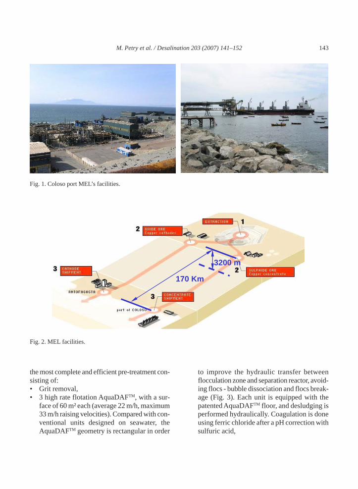
Degrémont was awarded in 2004 the construc-tion of a 45,360 m3/d reverse osmosis desalinationplant for Minera Escondida Limitada (MEL). Thisplant is part of its Sulphide Leach Project whichaims at increasing the production. The new plantis located on the North Coast of Chile at MELfacilities of Coloso Port, 15 km south of Antofa-gasta city (Fig. 1). The desalinated water producedon site will then be pumped to the second largestopen-pit copper mine in the world, 170 km awayfrom the coast and up to an altitude of 3200 mabove the sea level (Fig. 2). This desalination plantwill be the largest one in South America.
The North Coast of Chile could suffer, all-yearround, from high algae and TOC concentrations.The poorest water quality has been observed dur-ing “red-tides” events (red algae bloom). The feed-back from two small SWRO plants built in the90s for two different Chilean thermal power plants(Atacama and Mejillones) confirmed that a twostages pre-treatment (DAF and single stage mono-
media filtration) was not enough. Indeed, this pre-treatment is giving good clarification results main-taining the pre-treated water SDI below 4%/minmost of the time but cannot lower it below 3%/minespecially during high peaks of raw water SDI.
Consequently, Degrémont’s challenge was todesign a more effective pre-treatment line thatcould maintain, 90% of the time, pre-treated wa-ter’s SDI below 3%/min whatever the raw waterquality.
In addition, a high RO recovery rate has beendecided (50%) together with an innovative mem-brane arrangement (hybrid) to maintain a correctflow pattern throughout the pressure vessels forthe whole range of temperature (11–23°C) and toprovide a better permeate quality without affectingsignificantly the feed pressure.
2. The El Coloso SWRO design
In order to face the worst seawater quality ofthe region, Degrémont’s design includes one of
M. Petry et al. / Desalination 203 (2007) 141–152 143
Fig. 2. MEL facilities.
170 Km
3200 m
Fig. 1. Coloso port MEL’s facilities.
the most complete and efficient pre-treatment con-sisting of:• Grit removal,• 3 high rate flotation AquaDAFTM, with a sur-
face of 60 m² each (average 22 m/h, maximum33 m/h raising velocities). Compared with con-ventional units designed on seawater, theAquaDAFTM geometry is rectangular in order
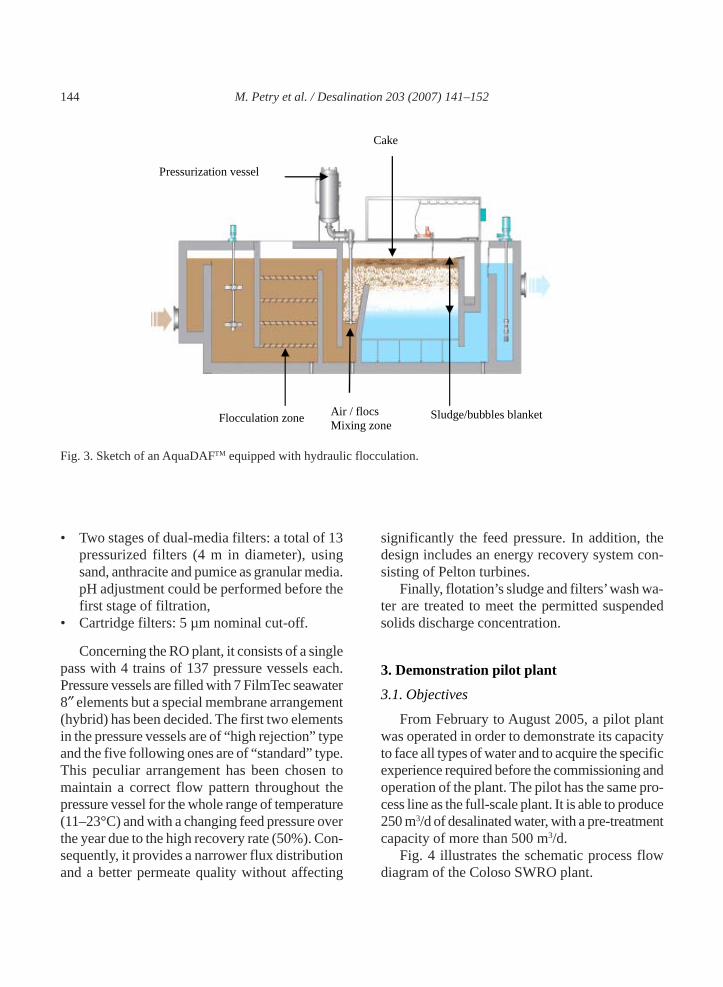
to improve the hydraulic transfer betweenflocculation zone and separation reactor, avoid-ing flocs - bubble dissociation and flocs break-age (Fig. 3). Each unit is equipped with thepatented AquaDAFTM floor, and desludging isperformed hydraulically. Coagulation is doneusing ferric chloride after a pH correction withsulfuric acid,
144 M. Petry et al. / Desalination 203 (2007) 141–152
• Two stages of dual-media filters: a total of 13pressurized filters (4 m in diameter), usingsand, anthracite and pumice as granular media.pH adjustment could be performed before thefirst stage of filtration,
• Cartridge filters: 5 µm nominal cut-off.
Concerning the RO plant, it consists of a singlepass with 4 trains of 137 pressure vessels each.Pressure vessels are filled with 7 FilmTec seawater8″ elements but a special membrane arrangement(hybrid) has been decided. The first two elementsin the pressure vessels are of “high rejection” typeand the five following ones are of “standard” type.This peculiar arrangement has been chosen tomaintain a correct flow pattern throughout thepressure vessel for the whole range of temperature(11–23°C) and with a changing feed pressure overthe year due to the high recovery rate (50%). Con-sequently, it provides a narrower flux distributionand a better permeate quality without affecting
Fig. 3. Sketch of an AquaDAFTM equipped with hydraulic flocculation.
Pressurization vessel
Cake
Flocculation zone Air / flocs Mixing zone
Sludge/bubbles blanket
significantly the feed pressure. In addition, thedesign includes an energy recovery system con-sisting of Pelton turbines.
Finally, flotation’s sludge and filters’ wash wa-ter are treated to meet the permitted suspendedsolids discharge concentration.
3. Demonstration pilot plant
3.1. Objectives
From February to August 2005, a pilot plantwas operated in order to demonstrate its capacityto face all types of water and to acquire the specificexperience required before the commissioning andoperation of the plant. The pilot has the same pro-cess line as the full-scale plant. It is able to produce250 m3/d of desalinated water, with a pre-treatmentcapacity of more than 500 m3/d.
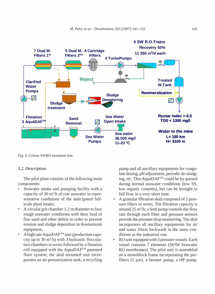
Fig. 4 illustrates the schematic process flowdiagram of the Coloso SWRO plant.
M. Petry et al. / Desalination 203 (2007) 141–152 145
Fig. 4. Coloso SWRO treatment line.
3.2. Description
The pilot plant consists of the following maincomponents:• Seawater intake and pumping facility with a
capacity of 30 m3/h of raw seawater in repre-sentative conditions of the anticipated full-scale plant intake,
• A circular grit chamber 1.2 m diameter to facerough seawater conditions with their load offine sand and other debris in order to preventerosion and sludge deposition in downstreamequipment,
• A high rate AquaDAFTM unit (production capa-city up to 30 m3/h) with 3 hydraulic floccula-tion chambers in series followed by a flotationcell equipped with the AquaDAFTM patentedfloor system; the skid mounted unit incor-porates an air pressurization tank, a recycling
pump and all ancillary equipments for coagu-lant dosing, pH adjustment, periodic de-sludg-ing, etc. This AquaDAFTM could be by-passedduring normal seawater conditions (low SS,low organic contents), but can be brought tofull flow in a very short time.
• A granular filtration skid composed of 2 pres-sure filters in series. The filtration capacity isaround 25 m3/h; a feed pump controls the flowrate through each filter and pressure sensorsprovide the pressure drop monitoring. The skidincorporates all ancillary equipments for airand water filters backwash in the same con-ditions as the industrial one.
• RO unit equipped with 3 pressure vessels. Eachvessel contains 7 elements (DOW SeawaterRO membranes). The pilot unit is assembledon a monoblock frame incorporating the pre-filters (5 µm), a booster pump, a HP pump,
4 CartridgeFilters
4 TurboPumps
4 SW R.O.TrainsRecovery 50%
11 350 m3/d each
Reject Treated W.Tank
IF
IF
IF
ClarifiedWater Pumps
7 Dual M.Filters 1st
Sea Water Pumps
Sea WaterOpen Intake
Flotation 3 AquaDAFTM I
FI
FI
F
5 Dual M.Filters 2nd
SandRemoval
Sea water 36.500 mg/l11-23 ºC
TDS < 1300 mg/lRyznar Index > 6.5
TDS < 1300 mg/lRyznar Index > 6.5
Water to the mineL= 180 kmH= 3100 m
Water to the mineL= 180 kmH= 3100 m
IF
IF
IF
Remineralization Remineralization Sludge Dewatering
Sludge treatment

146 M. Petry et al. / Desalination 203 (2007) 141–152
dosing equipments and the pressure vessels. Itallows for an independent loop control of thefeed flow, working pressure, dosing of anti-scalant and caustic soda if a pH correction isrequired. It is equipped with 2 flowmeters(permeate and concentrate flows), 3 pressuregauges to monitor precisely the membraneshead loss over time. The maximum permeateproduction capacity is around 12 m3/h.
3.3. Results
3.3.1. Preliminary lab-scale pre-treatment tests
A two week lab-scale tests were performed in2004 in order to confirm the design of the pre-
treatment and to fine-tune the operating parame-ters for the pilot-scale tests.
As expected, the raw seawater was of poorquality and with an important quantity of sus-pended particles, mainly algae and algae debris(Fig. 5). Direct coagulation and filtration on adual-media filter gave poor results: SDI valuesremained between 4 and 5%/min, even at theoptimum pH and with a residual concentration ofiron below 10 µg/L. Moreover, filter’s ripeningtook at least one hour at full filtration velocity toreach a stable filtered water quality.
A two stages configuration has then been testedsuccessfully. First, a pre-clarification and separa-tion step by coagulation-flocculation with 10 mg/L
Fig. 5. Electronic microscopy pictures of membranes used for SDI determination of raw seawater.

M. Petry et al. / Desalination 203 (2007) 141–152 147
of FeCl3 at a pH of 7.1. Secondly, a coagulationfollowed by a dual-media filtration that is actingas a polishing step.
This solution gave much better treated waterquality, with SDI values around 2.5%/min, andfilter’s ripening were significantly reduced. Also,residual iron was below the detection limit of5 µg/L.
Nevertheless, as these tests were done with a“relatively” good seawater quality, the full-scaletreatment line had to be completed by a secondstep dual-media filtration to insure a high reliabi-lity of the pre-treatment, especially during redtides.
3.3.2. Pilot test
3.3.2.1. Raw seawater quality
Table 1 presents the main characteristics of theraw seawater during the test.
Adapted SDI75% definition:
ASTM standard method for SDI measurementhas been adapted in order to measure SDI above5%/min. Measurements are not done in 15 minutesbut in the necessary time to get a 75% cloggingof the filtering membrane. It allows getting a sig-nificant SDI value even for poor raw seawaterqualities.
Considering El Coloso site’s coast profile(small continental table) and the absence of directinfluence from continental water, SDI and tur-bidity are relatively high. Turbidity and SDI havea global tendency to increase jointly but there isno tight correlation between them (Fig. 6).
As it was noticed during the lab-scale tests,plankton is ubiquitous in that area, even out ofbloom periods. When the concentration of algaeis rising, diatoms largely dominate the algae popu-lation meaning that the increase in algae concen-tration is mainly due to diatom blooms.
This important concentration of algae couldexplain the high level of SDI measured. Indeed,during the period from February to August 2005,
Table 1Raw water characteristics during the test period (Febru-ary–August 2005)
Parameters Range Temperature, °C 13–18 pH 7.4–7.9 Turbidity, NTU 0.1–2.0 Adapted SDI75%, %/min 4–40 Conductivity, mS/cm 52 TOC, mg/L 1.0–2.0 Chlorides, mg/L 19,600 Calcium, mg/L 435 Sodium, mg/L 11,100 Potassium, mg/L 390 Magnesium, mg/L 1340 Boron, mg/L 4.9 Bromide, mg/L 62 Carbonate, mg/L 0 HCO3, mg/L 152.5 Sulphate, mg/L 2930 Strontium, mg/L 7.7 SiO2, mg/L 0.41 Aluminium, µg/L <10 Barium, µg/L <10 Iron, µg/L <10 Manganese, µg/L <2 Fluoride, mg/L 1.25 Algae (% diatoms), Nb/mL 2–255 (8–100%)
the worst seawater quality was encountered inMarch with a “red tide” episode of twenty dayscorresponding to very high SDIs (Fig. 7). Then,the SDI decreased down until a relative stabiliza-tion in June (corresponding to the winter period).
3.3.2.2. Pre-treated water quality
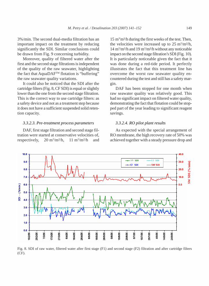
All along the tests period, the pilot plant hasachieved producing a pre-treated water’s SDIbelow 3%/min more than 90% of the time,demonstrating the efficiency of such a treatmentline even when facing very bad seawater quality(Fig. 8).
As it can be seen in Fig. 8, it is clear that flota-tion plus one stage dual-media filtration is notenough to reach the targeted SDI of less than

148 M. Petry et al. / Desalination 203 (2007) 141–152
Fig. 6. Correlation between SDI and turbidity of raw seawater.
Fig. 7. SDI of raw seawater during the test period.
M. Petry et al. / Desalination 203 (2007) 141–152 149
3%/min. The second dual-media filtration has animportant impact on the treatment by reducingsignificantly the SDI. Similar conclusions couldbe drawn from Fig. 9 concerning turbidity.
Moreover, quality of filtered water after thefirst and the second stage filtrations is independentof the quality of the raw seawater, highlightingthe fact that AquaDAFTM flotation is “buffering”the raw seawater quality variations.
It could also be noticed that the SDI after thecartridge filters (Fig. 8, CF SDI) is equal or slightlylower than the one from the second stage filtration.This is the correct way to use cartridge filters: asa safety device and not as a treatment step becauseit does not have a sufficient suspended solid reten-tion capacity.
3.3.2.3. Pre-treatment process parameters
DAF, first stage filtration and second stage fil-tration were started at conservative velocities of,respectively, 20 m3/m²/h, 11 m3/m²/h and
Fig. 8. SDI of raw water, filtered water after first stage (F1) and second stage (F2) filtration and after cartridge filters(CF).
SW S
DI (
%/m
in)
15 m3/m²/h during the first weeks of the test. Then,the velocities were increased up to 25 m3/m²/h,14 m3/m²/h and 19 m3/m²/h without any noticeableimpact on the second stage filtration’s SDI (Fig. 10).It is particularly noticeable given the fact that itwas done during a red-tide period. It perfectlyillustrates the fact that this treatment line hasovercome the worst raw seawater quality en-countered during the test and still has a safety mar-gin.
DAF has been stopped for one month whenraw seawater quality was relatively good. Thishad no significant impact on filtered water quality,demonstrating the fact that flotation could be stop-ped part of the year leading to significant reagentsavings.
3.3.2.4. RO pilot plant results
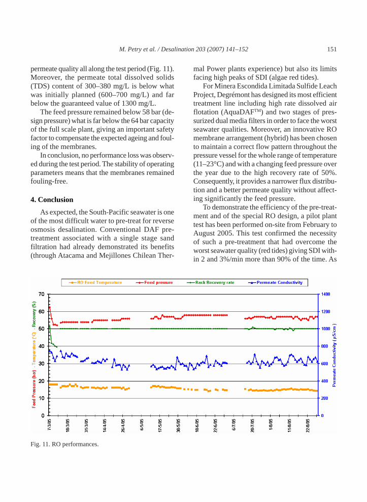
As expected with the special arrangement ofRO membrane, the high recovery rate of 50% wasachieved together with a steady pressure drop and

150 M. Petry et al. / Desalination 203 (2007) 141–152
Fig. 9. Turbidity reduction.
Fig. 10. SDI and velocities of the pre-treatment steps.
M. Petry et al. / Desalination 203 (2007) 141–152 151
permeate quality all along the test period (Fig. 11).Moreover, the permeate total dissolved solids(TDS) content of 300–380 mg/L is below whatwas initially planned (600–700 mg/L) and farbelow the guaranteed value of 1300 mg/L.
The feed pressure remained below 58 bar (de-sign pressure) what is far below the 64 bar capacityof the full scale plant, giving an important safetyfactor to compensate the expected ageing and foul-ing of the membranes.
In conclusion, no performance loss was observ-ed during the test period. The stability of operatingparameters means that the membranes remainedfouling-free.
4. Conclusion
As expected, the South-Pacific seawater is oneof the most difficult water to pre-treat for reverseosmosis desalination. Conventional DAF pre-treatment associated with a single stage sandfiltration had already demonstrated its benefits(through Atacama and Mejillones Chilean Ther-
mal Power plants experience) but also its limitsfacing high peaks of SDI (algae red tides).
For Minera Escondida Limitada Sulfide LeachProject, Degrémont has designed its most efficienttreatment line including high rate dissolved airflotation (AquaDAFTM) and two stages of pres-surized dual media filters in order to face the worstseawater qualities. Moreover, an innovative ROmembrane arrangement (hybrid) has been chosento maintain a correct flow pattern throughout thepressure vessel for the whole range of temperature(11–23°C) and with a changing feed pressure overthe year due to the high recovery rate of 50%.Consequently, it provides a narrower flux distribu-tion and a better permeate quality without affect-ing significantly the feed pressure.
To demonstrate the efficiency of the pre-treat-ment and of the special RO design, a pilot planttest has been performed on-site from February toAugust 2005. This test confirmed the necessityof such a pre-treatment that had overcome theworst seawater quality (red tides) giving SDI with-in 2 and 3%/min more than 90% of the time. As
Fig. 11. RO performances.
152 M. Petry et al. / Desalination 203 (2007) 141–152
flotation could be stopped and easily started againwithin an hour, it is possible to by-pass it duringbetter seawater qualities, reducing significantlycoagulant consumption over the year.
The RO operation at a high recovery of 50%showed steady flux, salt rejection and pressuredrop, meaning low fouling rate, either mineral or
organic and, thanks to the combination of mem-branes, an excellent permeate TDS lower than400 mg/l for a warranted one of 1300 mg/l. It isexpected that this combination of membranesallows a high recovery together with a low per-meate salinity over the temperature range experi-enced at El Coloso site.
Related Documents