This is a preprint of a paper that has been su bmitted for publicati on in the Journal of Cor rosion Sci ence and Engineering. It will be reviewed and, subject to the reviewers’ comments, be published online at http://www.umist.ac.uk/corrosion/jcse in due course. Until such time as it has been fully published it shou ld not normally be referenc ed in published work. © UMIST 2004. ISSN 1466-8858 Volume 9 Paper 3 The Effect of Surface Films on Cathod c Protection S.S. Leeds and R.A. Cottis Corrosion and Protection Centre, School of Materials, University of Manchester, P.O. Box 88, Manchester M60 1QD, UK, [email protected], [email protected] Abstract Electrochemical studies, surface chemistry and analytical analysis have been used to establish what is actually happening when steel samples are cathodically protected at a series of potentials in aerated pure 3.5% NaCl solution. It was found that under freely corroding conditions of -671 mV (Ag/AgCl/3.5 % NaCl) at day 30, the corrosion rate was 0.752 mm/yr, whilst a potentiostatic -650 mV and a battery driven CP specimens had corrosion rates of 0.089 and 0.099 mm/yr respectively. This was an 8 times reduction in corrosion rate compared to the freely corr oding specimen and shows that the appli cation of even a smal l amount of Cathodic Protection (CP) produces a significant reduction in corrosion. However it was not enough to halt corrosi on completely. Films were obse rv ed to form and these si gni ficantly affected the current demand and corrosion rate of the tes t specimens. The specimen with the least corrosion rate and most coherent film was at -1300 mV (Ag/AgCl/3.5% NaCl), with a corrosion rate of 0.00396 mm/yr. Keywords: Cathodic Protection, el ectro che mistr y, potentiostatic method, weight loss measurement.

Welcome message from author
This document is posted to help you gain knowledge. Please leave a comment to let me know what you think about it! Share it to your friends and learn new things together.
Transcript
8/3/2019 The Effect of Surface Films on Cathodic Protection
http://slidepdf.com/reader/full/the-effect-of-surface-films-on-cathodic-protection 1/20
This is a preprint of a paper that has been submitted for publication in the Journal of Corrosion Science
and Engineering. It will be reviewed and, subject to the reviewers’ comments, be published online at
http://www.umist.ac.uk/corrosion/jcse in due course. Until such time as it has been fully published it
should not normally be referenced in published work. © UMIST 2004.
ISSN 1466-8858
Volume 9 Paper 3
The Effect of Surface Films on Cathodic
Protection
S.S. Leeds and R.A. Cottis
Corrosion and Protection Centre, School of Materials, University of
Manchester, P.O. Box 88, Manchester M60 1QD, UK,[email protected], [email protected]
Abstract
Electrochemical studies, surface chemistry and analytical analysis have
been used to establish what is actually happening when steel samples
are cathodically protected at a series of potentials in aerated pure 3.5%
NaCl solution. It was found that under freely corroding conditions of
-671 mV (Ag/AgCl/3.5 % NaCl) at day 30, the corrosion rate was
0.752 mm/yr, whilst a potentiostatic -650 mV and a battery driven CP
specimens had corrosion rates of 0.089 and 0.099 mm/yr respectively.
This was an 8 times reduction in corrosion rate compared to the freely
corroding specimen and shows that the application of even a small
amount of Cathodic Protection (CP) produces a significant reduction in
corrosion. However it was not enough to halt corrosion completely.
Films were observed to form and these significantly affected the
current demand and corrosion rate of the test specimens. The
specimen with the least corrosion rate and most coherent film was at
-1300 mV (Ag/AgCl/3.5% NaCl), with a corrosion rate of
0.00396 mm/yr.
Keywords: Cathodic Protection, electrochemistry, potentiostatic
method, weight loss measurement.

8/3/2019 The Effect of Surface Films on Cathodic Protection
http://slidepdf.com/reader/full/the-effect-of-surface-films-on-cathodic-protection 2/20
2
Introduction
Corrosion is a significant and undesirable spontaneous
electrochemical process that costs billions of pounds each year in
terms of replacement and maintenance costs. To mitigate corrosion
one process involves the application of Cathodic Protection (CP) to
buried or immersed metallic structures. Various international
standards/specifications set out the application and control of CP but
do not give consideration to the electrochemistry and surface
chemistry of the metallic structure/electrolyte interface [1] [2] [3] [4]. The
ISO Standard [5] is more definitive, describing CP in terms of what is
actually happening electrochemically at the metal/electrolyte interface
of a cathodically polarized structure. It defines CP as, “Electrochemical
Protection achieved by decreasing the structure potential to a level
whereby the corrosion rate of metal is significantly reduced” but still
fails to provide information regarding the nature and role of the
interface or influence of surface films that form as a direct cause of the
cathodic protection process. Furthermore, it ignores the changes in
the chemistry of the environment that are induced by the applied
cathodic current.
For immersed structures the -800 to -1050 mV ( Ag/AgCl) polarised
potential is assumed by industry [2] to give protection under aerobic
conditions. For buried structures CP criteria such as the -850 mV
(Cu/CuSO4) OFF or the -100 mV shift [6] are used. These criteria are
based on the assumption that if a certain amount of current is applied
to the metallic structure of interest and it meets the protection criteria
then it must be protected. However, this is not always the case; for
example some pipelines having reportedly met a protection criteriasuch as -850 mV (Cu/CuSO4) OFF, have been found through metal loss
identification to be not fully protected some years later [6]. The
conditions for protection are more complex than simply applying more
and more current and measuring the resultant potential to achieve a
set criterion. What is important is knowing what is happening
electrochemically at the metal/electrolyte interface and adjusting the
criterion accordingly to achieve an acceptable corrosion rate.
8/3/2019 The Effect of Surface Films on Cathodic Protection
http://slidepdf.com/reader/full/the-effect-of-surface-films-on-cathodic-protection 3/20
3
Electrochemical Analysis of CP
When applying CP for the first time to a structure it is well known that
a higher current and less negative structure/electrolyte potential is
observed. Over a period of a week or more the current decreases and
the voltage becomes more negative until it reaches a stable value
determined by the amount of CP applied. Within the CP industry it is
stated that the surface has passivated, but does the industry really
understand what this means? In order to understand CP and the
nature of the "passivity" it is important to know what is actually
happening electrochemically at the surface of the metallic structure
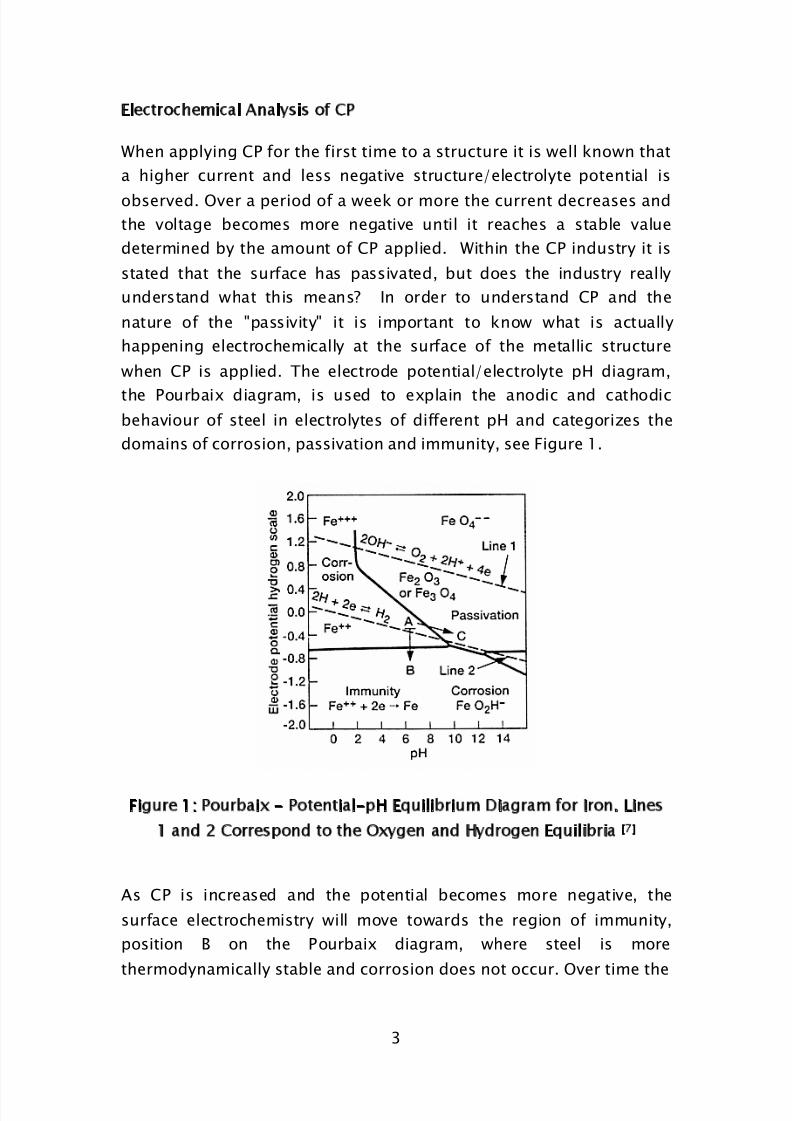
when CP is applied. The electrode potential/electrolyte pH diagram,
the Pourbaix diagram, is used to explain the anodic and cathodic
behaviour of steel in electrolytes of different pH and categorizes the
domains of corrosion, passivation and immunity, see Figure 1.
Figure 1: Pourbaix - Potential-pH Equilibrium Diagram for Iron. Lines
1 and 2 Correspond to the Oxygen and Hydrogen Equilibria [7]
As CP is increased and the potential becomes more negative, the
surface electrochemistry will move towards the region of immunity,
position B on the Pourbaix diagram, where steel is more
thermodynamically stable and corrosion does not occur. Over time the
8/3/2019 The Effect of Surface Films on Cathodic Protection
http://slidepdf.com/reader/full/the-effect-of-surface-films-on-cathodic-protection 4/20
4
surface pH will increase as a result of the generation of alkalinity due
to the reduction of dissolved oxygen [7] [8] .
-
22OH22OH½O
e Cathodic Reaction (1)
The effect of applying CP is therefore to move the potential in both a
negative direction and towards a higher pH to the conditions found in
the passive region at position C on the Pourbaix diagram which may
be above the potential required for immunity.
In cases where the potential is more negative [6] [9], a second cathodic
reaction occurs:
OH H e 22OH2 22 Cathodic Reaction (2)
In both cathodic reactions, hydroxyl ions are being formed which bring
about an increase in the electrolyte pH adjacent to the metal surface
and pushing the surface electrochemistry into the passive domain of
the Pourbaix diagram where films are formed.
Whilst the positions of the domain boundaries of the Pourbaix diagram
are variable depending upon ion concentration, temperature, pressure
etc, an interpretation of the Pourbaix Diagram suggests that the
domain potential (line 2, Figure1) for the decomposition of water has a
limiting potential for effective CP and that in practice the real structure
potential seldom reaches the domain of immunity unless the limiting
current density for water decomposition is reached which will never
happen in sea water. Increasing the applied potential between the
anode and cathode, a common practice to improve the distribution of
CP, only leads to more rapid generation of alkali with detrimental
effects of more rapid coating decay [10].
Studies of the Effect of Cathodic Protection on Surface Films
The initial cathodic reaction involving the reduction of dissolved
oxygen is limited by the fact that only small amounts of oxygen
(typically 8ppm) [11] can dissolve in water so for an increase in CP the
potential has to become more cathodic leading to the decomposition
of water for which under most conditions the limiting current density
is never reached. Alkali is generated by both cathodic reactions. In

8/3/2019 The Effect of Surface Films on Cathodic Protection
http://slidepdf.com/reader/full/the-effect-of-surface-films-on-cathodic-protection 5/20
5
the process of applying cathodic protection there will be a corrosion
reaction that is being progressively suppressed as the potential is
made more cathodic. Corrosion product is formed at a slower and
slower rate as the CP becomes more effective. What happens to this
corrosion product? It is believed that, like the formation of protective
calcareous deposits when steel is polarized in seawater [12] [13], there is
also a protective film formed from this iron corrosion product. The
combined effect is to reduce the area of bare steel exposed to the
electrolyte. To date studies of the role of surface films in CP have
concentrated on the build up of calcareous deposits in seawater
largely ignoring any effects of true passive films.
Previous work by Rodrigo [14] showed that the CP current density for
both 3 % NaCl solution and natural seawater was a function of
dissolved oxygen concentration. Under conditions of air saturation,
approximately 7 mg/L O2, 50 % less current was required to polarize
steel in natural seawater than in 3 % NaCl, he suggested that the
calcareous deposits were the main influencing factor.
Hartt et al. [15], studying calcareous deposits, found that extended
exposure time is required to achieve steady state, which suggests thatpotential and current should be treated as individual variables. This
can be seen when calcareous deposits are formed under certain
conditions promoting different current density decay responses. Hartt
et al., like Wolfson [16], found that long term, the current density did
not necessarily correlate with the magnitude of polarization. Hartt et
al. thought that the magnitude of current density should be
proportional to the magnitude of the cathodic polarization and that
the current density decay for the initial 10 hour exposure period of their specimens should be the same for all three potentials (-0.78 V,
0.93 V and -1.03 V (SCE) ). However, they found that the decay rate
for the -1.03 V (SCE) specimen increased, resulting in current
densities that after 30 hours were less than for the -0.93 V (SCE)
specimen. They suggested that this must be due to some property of
the calcareous deposit formed at the more negative potential that
upset the expected potential /current density relationship. It was
thought that this could be due to a greater resistivity or specific
chemistry of the -1.03 V (SCE) deposits/films.

8/3/2019 The Effect of Surface Films on Cathodic Protection
http://slidepdf.com/reader/full/the-effect-of-surface-films-on-cathodic-protection 6/20
6
Humble [17] found that calcareous deposits/films formed at lower
current densities were more permanent than those formed at higher
current densities. Cox [18] further found that no corrosion was apparent
when the cathodic current density was in the range of 0.07 to
0.3 mA/cm2. Thus, the surface films formed under these conditions
provided enough protection even during the time of the experiment
when the specimens were out of the water. Further this was argued as
being proof that protection was attributed to the chemistry of the
calcareous films formed and that the reduced protection of films was
attributed to current densities that were greater than 0.3 mA/cm2 and
were due to the poor coating properties of Mg(OH)2. None of these
authors mention the impact of any iron corrosion product films. The
observations reported in this paper deal with studies of the iron
corrosion product films on mild steel using as electrolyte an aerated
pure 3.5 % sodium chloride (NaCl), pH 7 in order to eliminate possible
calcareous deposit interference.
EXPERIMENTAL PROCEDURE
Materials
Tests were carried out on bright mild steel specimens manufactured
according to BS. 970 Pt3, 1991, having a composition given in Table 1.
Table 1: Composition of the Mild Steel used in the Experimental Work
C Si Mn P S
0.120 % 0.180 % 0.850 % 0.026 % 0.031 %
Each specimen was cylindrical in shape, 0.6 cm diameter and 4 cm inlength. The specimens were prepared by abrading with 1200 grit
silicon carbide paper, then cleaned and degreased in acetone and
preweighed.
The test electrolyte was a solution of 3.5 % w/v Analar grade sodium
chloride (NaCl) in deionised water.
8/3/2019 The Effect of Surface Films on Cathodic Protection
http://slidepdf.com/reader/full/the-effect-of-surface-films-on-cathodic-protection 7/20
7
Test Cell
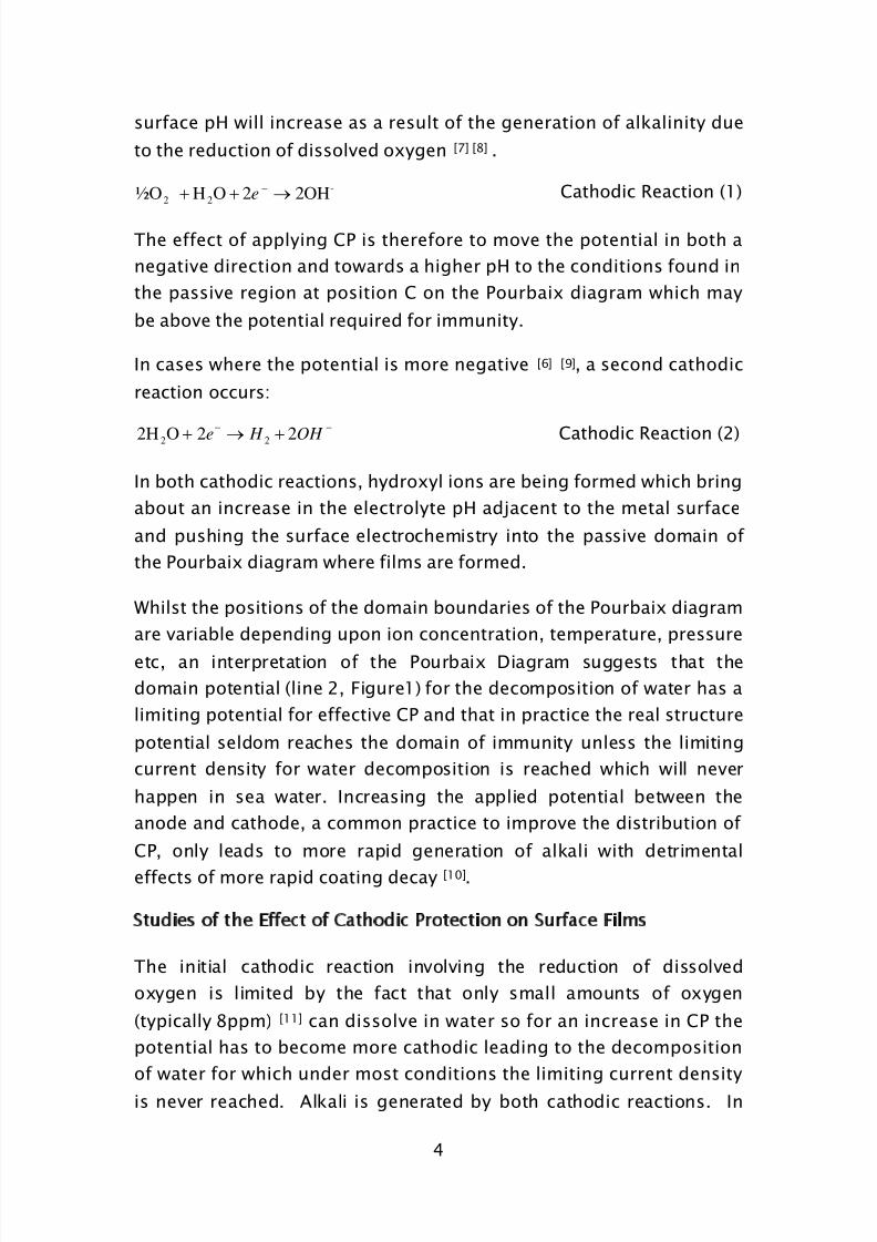
To separate anode and cathode reactions and to limit any effects of
chlorine from the anodic reaction a test rig was constructed such that
it had concentric inner and outer cells. The plastic walled inner cell had
holes in the bottom covered with an agar gel made up with 3.5 % NaCl
solution to allow for ionic exchange and glass beads to weigh it down.
This inner cell held the test specimen (WE), Ag/AgCl/3.5% NaCl
reference electrode and air bubbler. The reference electrode was
constructed out of a 40 cm, 0.6 cm PVC tube. This was filled with agar,
in 3.5 % NaCl and an activated Ag/AgCl electrode, calibrated against a
standard Ag/AgCl electrode. The reference electrode was constructed
in this way to limit the migration of silver ions onto the steel
specimens because Scanning Electron Microscopy (SEM) analysis of
earlier films on the steel specimens, found silver deposited when the
RE were constructed in a typical Luggin capillary design or if the
Ag/AgCl reference electrode was directly in the electrolyte solution.
Graphite anodes were arranged in a triangular configuration to allow
for an even spread of the current, see Figure 2.
Inner Cell
Outer Cell
Anode REAir Bubbler
E
Agar Gel
3.5% NaCl
Figure 2: Test cell configuration
RE: Ag/AgCl/3.5% NaCl
Reference Electrode
WE: Mild Steel Working
Electrode

8/3/2019 The Effect of Surface Films on Cathodic Protection
http://slidepdf.com/reader/full/the-effect-of-surface-films-on-cathodic-protection 8/20
8
Potentiostatic and Weight Loss Methods
Eight test specimens were investigated and each was connected to a
separate potentiostat. The potentials of the specimens were controlled
in the range -650 to -1300 mV (Ag/AgCl/3.5% NaCl). A further
specimen was exposed to freely corroding conditions (initially
-526 mV, moving to approximately -671 mV (Ag/AgCl/3.5% NaCl)
over a period of 720 hrs). An additional specimen was connected to a
battery and variable resistor and set initially to a potential of -650 mV
(Ag/AgCl/3.5% NaCl) with no permanent reference electrode and used
primarily as a control to check for silver contamination when carrying
out SEM analysis. The specimens were exposed for 30 days in pure
3.5 % aerated NaCl solution. The current for each specimen was
recorded automatically every 15 minutes. Specimens were then
cleaned according to the ASTM G1 specification [19]. A second
unexposed control specimen was also cleaned to correct for any
cleaning procedure weight loss and resulted in a correction factor of
0.0002 mm/yr.
Film Preparation for SEM Analysis
At the end of the exposure time sections of the films formed were
detached and transferred onto double sided carbon impregnated tape
then placed in a vacuum overnight at 10-2 Torr. These films were then
analyzed in the SEM in order to identify the composition of the films.
The films on the metal specimens were also examined directly for
comparison with the detached films.
RESULTS
Specimen Morphology
Observations were made to log any changes in specimen morphology.
The freely corroding specimen (-671 mV (Ag/AgCl/3.5% NaCl)
developed a blue/green deposit by the end of day one, suggesting that
this was hydrated magnetite, Fe3O4.H2O, an unstable form of rust. This
soon formed red brown flaky rust, hydrated ferric oxide. The -650 mV
potentiostatic specimen also formed red brown flaky rust, showing
that the initial application of CP does not stop the onset of corrosion.

8/3/2019 The Effect of Surface Films on Cathodic Protection
http://slidepdf.com/reader/full/the-effect-of-surface-films-on-cathodic-protection 9/20
9
The specimens with potentials ranging from -700, -800, -850, -900,
-950, -1000 and -1300 mV had progressively varying degrees of a
grey film forming slowly on the metal through out the 30 days, with
the more negative potentials forming a black film.
Analysis of Films
Samples of the films were collected and analyzed under SEM. It was
very difficult to take samples of the film as they are very thin and
adherent. Three or four different regions of the film were analyzed to
get an overall view of the composition. The films on the metal
specimens were also examined directly to observe any differences
between the sections of film taken and the film directly on thespecimens. Table 2 details the elemental composition of the films.
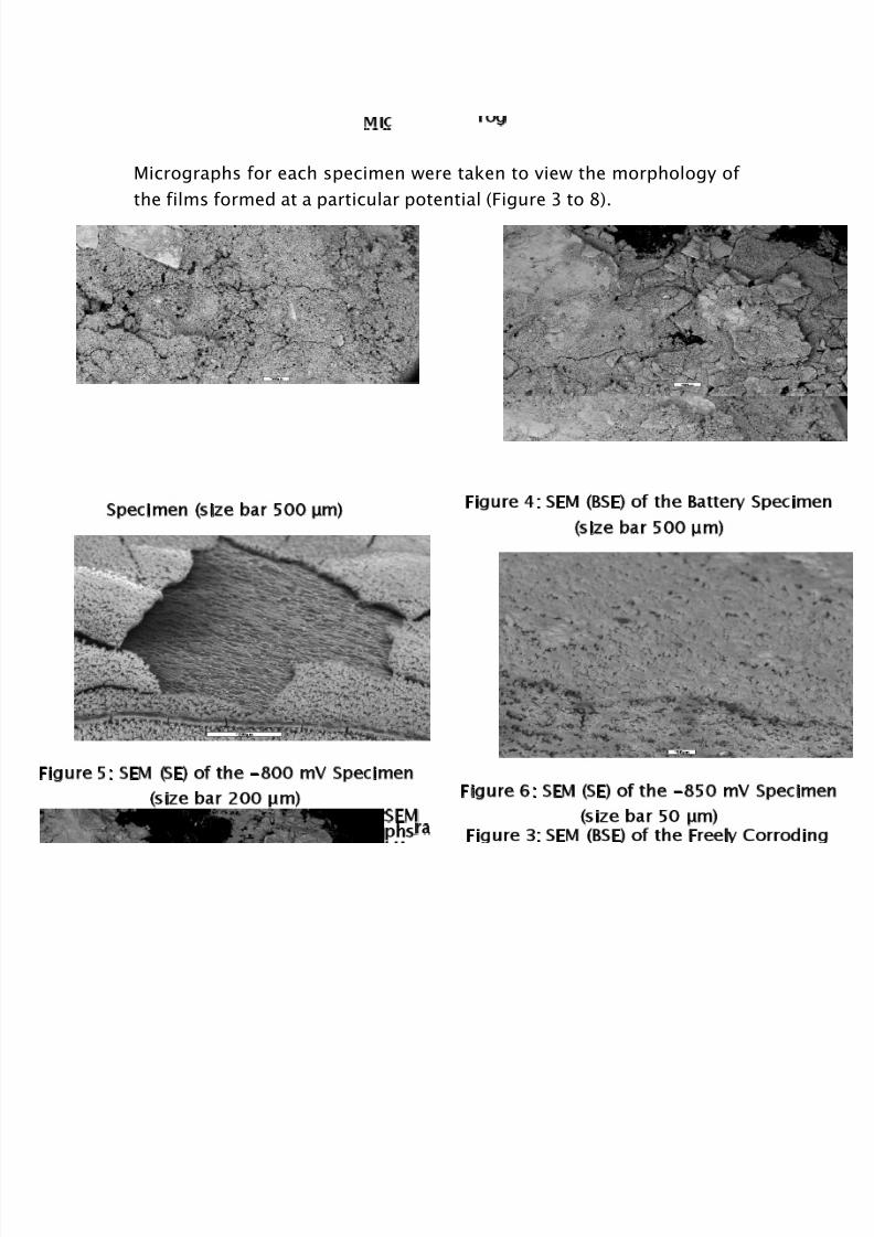
Figures 3 to 8 show the film structure. In each case sections of the
film and the film on the specimen are viewed. It can be seen that the
more negative the potential then the more uniform the film that is
formed, which is in agreement with the observations made during the
experiment. From the freely corroding to the -800 mV specimen the
films formed are looser and less coherent. From -850 mV to
-1300 mV the films were more uniform. It can be seen that the filmsform a compact structure, with a crystalline appearance. It is thought
that the film is composed of magnetite and probably accounts for the
reduction in corrosion as the specimen potentials are made more
negative.

8/3/2019 The Effect of Surface Films on Cathodic Protection
http://slidepdf.com/reader/full/the-effect-of-surface-films-on-cathodic-protection 10/20
10
Table 2: SEM Analysis
Freely Corroding to -1300mV Specimens
Specimen Potential
FreelyCorroding
Batter y -650 mV -700 mV -800 mV -850 mV -900 mV -95 0 mV -10 00 mV - 13 00 mV
Element A
%
A
%
A
%
A
%
A
%
A
%
A
%
A
%
A
%
A
%
C 15.64 16.79 44.72 - - 29.36 16.0 - 46.27 55.35
O 26.81 35.92 15.67 34.13 45.37 35.51 54.05 5.03 19.32 9.67
Na 14.37 9.48 13.93 22.85 9.57 5.97 5.45 8.22 4.79 5.43
Si 0.30 0.93 0.93 4.07 6.79 4.23 1.04 4.58 0.12 0.25
S 1.60 0.21 0.30 0.42 1.12 0.69 0.09 - 7.02 0.49
Cl 13.27 7.83 15.79 21.5 6.68 4.17 1.31 4.12 4.95 2.44
Cr 0.46*0.29 - - 0.28* 0.18* 0.04*
- 1.16 0.05*
Mn 1.98 0.61 - 0.37 1.02 0.66 0.56 1.38 6.75 0.16
Fe 26.30 28.25 8.46 14.76 28.94 19.03 39.3 30.54 24.56 21.78
Ca - - 0.20 0.83 0.26 0.17 - 0.85 - -
K - - 0.093 0.25*
- - - - - -
P - - 0.69 - - 0.01 - 0.17 0.25
Zn - - 1.33 - - - - - -
Cu - - - - 0.17*
-- - - -
A: % Atomic, * : <2 Sigma, Spectrum taken at 15kV, System resolution is 62
8/3/2019 The Effect of Surface Films on Cathodic Protection
http://slidepdf.com/reader/full/the-effect-of-surface-films-on-cathodic-protection 11/20
SEM Micrographs
Micrographs for each specimen were taken to view the morphology of
the films formed at a particular potential (Figure 3 to 8).
Figure 3: SEM (BSE) of the Freely Corroding
Specimen (size bar 500 μm)
Figure 4: SEM (BSE) of the Battery Specimen
(size bar 500 μm)
Figure 5: SEM (SE) of the -800 mV Specimen
(size bar 200 μm)
Figure 6: SEM (SE) of the -850 mV Specimen
(size bar 50 μm)
8/3/2019 The Effect of Surface Films on Cathodic Protection
http://slidepdf.com/reader/full/the-effect-of-surface-films-on-cathodic-protection 12/20
12
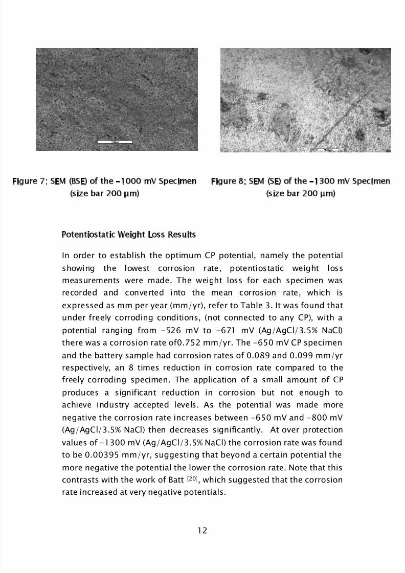
gure 7: SEM (BSE) of the -1000 mV Specimen
(size bar 200 μm)
Figure 8: SEM (SE) of the -1300 mV Specimen
(size bar 200 μm)
Potentiostatic Weight Loss Results
In order to establish the optimum CP potential, namely the potential
showing the lowest corrosion rate, potentiostatic weight loss
measurements were made. The weight loss for each specimen was
recorded and converted into the mean corrosion rate, which is
expressed as mm per year (mm/yr), refer to Table 3. It was found that
under freely corroding conditions, (not connected to any CP), with a
potential ranging from -526 mV to -671 mV (Ag/AgCl/3.5% NaCl)
there was a corrosion rate of0.752 mm/yr. The -650 mV CP specimen
and the battery sample had corrosion rates of 0.089 and 0.099 mm/yr
respectively, an 8 times reduction in corrosion rate compared to the
freely corroding specimen. The application of a small amount of CP
produces a significant reduction in corrosion but not enough to
achieve industry accepted levels. As the potential was made more
negative the corrosion rate increases between -650 mV and -800 mV
(Ag/AgCl/3.5% NaCl) then decreases significantly. At over protection
values of -1300 mV (Ag/AgCl/3.5% NaCl) the corrosion rate was found
to be 0.00395 mm/yr, suggesting that beyond a certain potential the
more negative the potential the lower the corrosion rate. Note that this
contrasts with the work of Batt [20], which suggested that the corrosion
rate increased at very negative potentials.
8/3/2019 The Effect of Surface Films on Cathodic Protection
http://slidepdf.com/reader/full/the-effect-of-surface-films-on-cathodic-protection 13/20
13
The corrosion rate plotted against specimen potential is given in
Figures 9. It is commonly considered by industry that a corrosion rate
of 0.001mm/yr [20] [21] represents an acceptable rate of metal loss . On
the basis of the data presented it suggests that the potentials in
excess of -1300 mV (Ag/AgCl/3.5% NaCl) would be needed to achieve
this industry level. However, the very negative potentials can give rise
to additional problems dealt with later.
Table 3: Potentiostatic Weight Loss Measurement Data
Specimen Weight Loss
(g)
Current
Density
(mA/cm2
) atDay 30
Corrosion Rate
(mm/yr)
Unexposed Control 0.0009 - 0.0002
Freely Corroding 0.38 - 0.752
Battery Controlled 0.05 - 0.099
-650mV 0.045 0.0742 0.089
-700mV 0.059 0.0473 0.116
-800mV 0.077 0.179 0.152
-850mV 0.052 0.193 0.103
-900mV 0.024 0.253 0.048
-950mV 0.012 0.129 0.024
-1300mV 0.002 0.914 0.00396

8/3/2019 The Effect of Surface Films on Cathodic Protection
http://slidepdf.com/reader/full/the-effect-of-surface-films-on-cathodic-protection 14/20
14
Figure 9: Corrosion Rate Plotted Against Specimen Potential at
Day 30
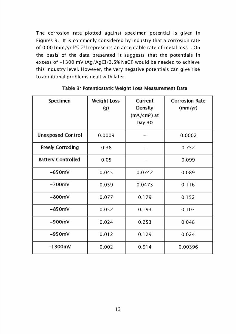
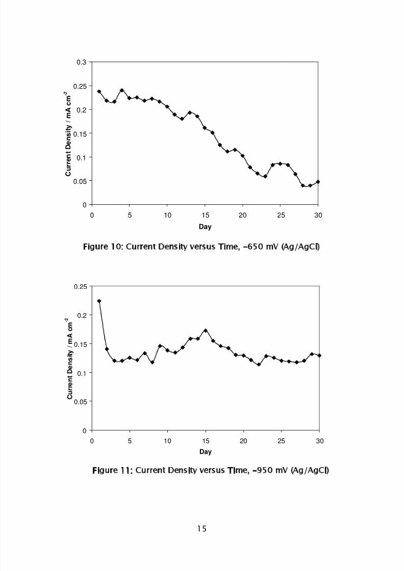
The current density plotted against time to determine the trend in the
amount of current required by a CP system operated at specific
potentials are shown in Figure 9 to Figure 12, for -650, -950 and
-1300 mV specimens respectively. At -650 mV (Ag/AgCl/3.5% NaCl)
the specimen showed a continued decrease in current required, but
the surface of the specimen was covered with a loose flakey red brown
corrosion product (but note that the average corrosion rate over the
exposure period was less than that for the free corrosion case, even
though the final potential of the latter was more negative than
-650 mV (Ag/AgCl/3.5% NaCl)). At -950 mV (Ag/AgCl/3.5% NaCl) after
an initial fall in current to day 3 the current demand stayed relatively
constant. The fluctuations in current are thought to be due to the
break away of some parts of the looser black film easily dislodged by
the agitated electrolyte as observed over the course of 30 days. At
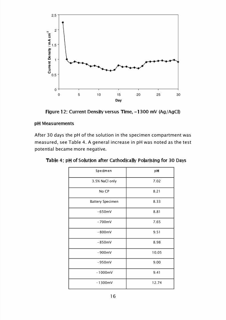
-1300 mV (Ag/AgCl/3.5% NaCl) after the big initial drop in current up
to day 3 the current remained steadier than for the -950 mV
specimen. The -1300 mV specimen was covered in a uniform black
film (subsequently shown to be magnetite). In practice the current to
which the specimens settle represent the current needed to maintain
an operational CP system.
-1400
-1300
-1200
-1100
-1000
-900
-800
-700
-600
-500
0.001 0.01 0.1 1
Current Density / mA cm2
P o t e n t i a l / m V ( A g / A g
C l )
Free CorrosionRange
Log Corrosion Rate (mm/yr)
8/3/2019 The Effect of Surface Films on Cathodic Protection
http://slidepdf.com/reader/full/the-effect-of-surface-films-on-cathodic-protection 15/20
15
0
0.05
0.1
0.15
0.2
0.25
0 5 10 15 20 25 30
Day
C u r r e n t D e n s i t y / m A c m - 2
Figure 10: Current Density versus Time, -650 mV (Ag/AgCl)
Figure 11: Current Density versus Time, -950 mV (Ag/AgCl)
0
0.05
0.1
0.15
0.2
0.25
0.3
0 5 10 15 20 25 30
Day
C u r r e n t D e n s i t y / m A c m
- 2
8/3/2019 The Effect of Surface Films on Cathodic Protection
http://slidepdf.com/reader/full/the-effect-of-surface-films-on-cathodic-protection 16/20
16
0
0.5
1
1.5
2
2.5
0 5 10 15 20 25 30
Day
C u r r e n t D e n s i t y / m A c m - 2
Figure 12: Current Density versus Time, -1300 mV (Ag/AgCl)
pH Measurements
After 30 days the pH of the solution in the specimen compartment was
measured, see Table 4. A general increase in pH was noted as the test
potential became more negative.
Table 4: pH of Solution after Cathodically Polarising for 30 Days
Specimen pH
3.5% NaCl only 7.02
No CP 8.21
Battery Specimen 8.33
-650mV 8.81
-700mV 7.65
-800mV 9.51
-850mV 8.98
-900mV 10.05
-950mV 9.00
-1000mV 9.41
-1300mV 12.74

8/3/2019 The Effect of Surface Films on Cathodic Protection
http://slidepdf.com/reader/full/the-effect-of-surface-films-on-cathodic-protection 17/20
17
Interpreting data from Tables 3 and 4 and using the Pourbaix Diagram,
it can be found that the freely corroding, the -650 mV and the battery
specimens lie on the border between corrosion and immunity, the
formation of red brown rust, hydrated Fe2O3.H2O suggesting that these
specimens lie more in the corrosion region, allowing corrosion to
continue throughout the 30 days, which can be confirmed by the
weight loss observed. The -800, -900, -1000 mV specimen solutions
are increasing in alkalinity. The -1300 mV specimen, at a pH of 12.7 is
on the border between immunity and corrosion, however in this case
there is not much corrosion occurring which must be due to the
protective film formed at the more negative potentials, as can be
confirmed by the limited weight loss observed. The problem with the
very negative potentials is the generation of excessive alkali, which will
lead to more rapid degradation of organic protective coatings and can
also lead to the build up of carbonate/bicarbonate environments, one
of the requirements for the development of Stress Corrosion Cracking
failures.
DISCUSSION
The experimental work carried out has enabled a better understandingof what is occurring at the metal/electrolyte interface when it is
cathodically polarized. The work confirmed that a cathode definitely
becomes covered with a protective film which could not be calcareous
deposit in these experiments. This film at more negative potentials is
thought to be magnetite and is grown only by the effect of the CP on
the steel surface. At less negative potentials the magnetite film can
become less coherent. The best film was at the more negative
potentials where water decomposition is giving rise to alkali and anincrease in surface pH, which, for reasons mentioned earlier, is not
desirable. Over protection gives an excessively alkaline pH and wastes
current and contributes very little to effective CP. The results suggest
that some decomposition of water is very important in order to
generate the best possible film, but this should be limited to reduce
unwanted current.
Corrosion can be halted if an adequate film can be formed on the
metal during cathodic polarization and the data suggest that a
8/3/2019 The Effect of Surface Films on Cathodic Protection
http://slidepdf.com/reader/full/the-effect-of-surface-films-on-cathodic-protection 18/20
18
minimum of 3 days is required for the film to start influencing what is
happening at the steel surface. The work poses a fundamental
question, what mechanism is providing the cathodic protection? Is
protection primarily the result of lowering the potential into or towards
the region of thermodynamic immunity, or is it the result of
passivating the steel by the formation of a film in the alkaline
environment resulting from the excess cathodic current or is it a
combined effect? Further experimentation is planned to interpret
better the fundamental mechanisms by which CP works in minimising
corrosion of mild steel.
CONCLUSIONS
Films were progressively formed over a 3 day period as a direct
result of cathodically polarizing metal specimens.
Longer times are needed to form coherent films.
X-Ray Diffraction has to be carried out to prove what the films
are composed of. It is thought that it is magnetite.
Application of a small amount of CP produced a significant
reduction in corrosion, which can be seen by the lower corrosion
rate of the -650 mV specimen compared to the freely corrodingspecimen. However, -650 mV was insufficient to prevent
corrosion from still occurring.
Industry states that to prevent corrosion of metallic structure a
potential of -950 mV (Ag/AgCl/seawater) should be used in
seawater. In the experimental conditions used in this study,
corrosion rates above 0.001mm/yr were still observed.
Making the potential more negative resulted in a lower corrosion
rate, with a potential of -1300 mV meeting an acceptablecorrosion rate of 0.001mm/yr. Further work has to be carried
out to confirm this result.
Modelling work is being carried out to try and understand
theoretically what is occurring at the electrolyte/metal interface
when cathodically polarised.
8/3/2019 The Effect of Surface Films on Cathodic Protection
http://slidepdf.com/reader/full/the-effect-of-surface-films-on-cathodic-protection 19/20
19
REFERENCES
1. RP0169-83, NACE Standard, Recommended Practice, Control of
External Corrosion on Underground or Submerged Metallic
Piping Systems: NACE, Houston, USA.
2. Cathodic Protection-Part 1: Code of Practice for Land and Marine
Applications, British Standard, BS 7361-1:1991, BSI.
3. Cathodic Protection of Metals Part 2: Compact buried structures,
Australian Standard, AS 2832.2-1991.
4. Cathodic Protection of Buried or Immersed Metallic Structures -
General Principles and Applications for Pipelines, British
Standard, BS EN 12954:2001, BSI.
5. ISO Standard 8044, Third Edition, Corrosion of Metals and Alloys
- Basic Terms and Definitions.
6. T.J. Barlow, Field Testing the Criteria for Cathodic Protection,
American Gas Association Catalogue No. L51546,1988.
7. Pourbaix.M, Atlas of Electrochemical Equilibria in Aqueous
Solutions. 1974: NACE, Houston.
8. L.L. Shrier, Corrosion Volumes 1 and 2: Butterworth & Co
Publishers.
9. Marine Directorate, Design and Operational Guidance on
Cathodic Protection of Offshore Structures, Subsea Installations
and Pipelines, 1990.
10. K. Kobayashi, Effect of Environmental Factors on Protective
Potential of Steel, Proceedings 5th International Congress on
Metallic Corrosion. 1974. NACE.
11. NDC, Seawater Corrosion Handbook, ed. M. Schumacher, 1979.
12. A. Neville and A.P. Morizot, Calcareous Scales Formed by
Cathodic Protection-an Assessment of Characteristics and
Kinetics. Journal of Crystal Growth 243: p. 490-502.
13. K.P. Fischer, W.H. Thomason and S. Eliassen, CP in Deep Water:
The importance of Calcareous Deposits and the Environmental
Conditions, in Corrosion 96, Paper No. 548: NACE International,
USA.
14. M.A.G. Rodrigo, Afinidad, 23: p. 217.
8/3/2019 The Effect of Surface Films on Cathodic Protection
http://slidepdf.com/reader/full/the-effect-of-surface-films-on-cathodic-protection 20/20
20
15. W.H. Hartt, C.H. Culberson, and S.W. Smith, Calcareous Deposits
on Metal Surfaces in Seawater - A Critical Review. Corrosion,
1984, 4(11): p. 609-618.
16. S.L. Wolfson and W.H. Hartt, Corrosion, 1981. 37(2): p. 70.
17. H.A. Humble, Corrosion, 1948, 4(7): p. 358.
18. F.L. Laque, Cox Quoted by Laque, Corrosion, 1950. 6: p. 161.
19. ASTM, G1-03: Standard Practice for Preparing, Cleaning, and
Evaluating Corrosion Test Specimens, 2003, ASTM International.
20. C. Batt and M.J. Robinson, Cathodic Protection Requirements for
High Strength Steel in Sea Water Assessed by Potentiostatic
Weight Loss measurements. British Corrosion Journal, 2002,
37(1): p. 31-36.
21. A.W. Peabody, Peabody's Control of Pipeline Corrosion. Second
Edition ed., R.L. Bianchetti, 2001: NACE.
Related Documents