i THE DESIGN OF AN ELECTRONIC VOTING MACHINE WITH A GSM MODULE By Ignatio Mangwayana (R14641M) Dissertation submitted in partial fulfilment of the requirement for the degree of BACHELOR OF SCIENCE HONOURS IN TELECOMMUNICATIONS ENGINEERING Department of Applied Physics and Telecommunications in the Faculty of Science and Technology Midlands State University Gweru, Zimbabwe November 2016 Supervisors: Dr C. Nyamhere and Mr F. Mazunga

Welcome message from author
This document is posted to help you gain knowledge. Please leave a comment to let me know what you think about it! Share it to your friends and learn new things together.
Transcript
i
THE DESIGN OF AN ELECTRONIC VOTING MACHINE WITH A
GSM MODULE
By
Ignatio Mangwayana (R14641M)
Dissertation submitted in partial fulfilment of the requirement for the degree of
BACHELOR OF SCIENCE HONOURS IN TELECOMMUNICATIONS
ENGINEERING
Department of Applied Physics and Telecommunications in the Faculty of Science and
Technology
Midlands State University
Gweru, Zimbabwe
November 2016
Supervisors: Dr C. Nyamhere and Mr F. Mazunga
ii
Abstract
The main objective of this project was to design a cost effective and efficient electronic voting
system interfaced with a GSM module. There is need to replace the conventional voting system
based on paper in Zimbabwe and many African countries by electronic voting machines which
are cheaper, more secure and less cumbersome.
Voting is when societies or a particular group of people come up with decisions based on choice
and or preferences hence the need for a cheaper, more secure, reliable, transparent and less
cumbersome system.
A voting system of this nature will significantly reduce the draining of the much needed
resources of the Zimbabwean economy and many other African countries. Costs linked to time,
personnel, accommodation, food, stationery and transport are significantly reduced.
iii
Declaration
I, Ignatio Mangwayana (R14641M) hereby declare that I am the sole author of this
dissertation entitled “The design of an Electronic Voting System with GSM module”. I
authorize Midlands State University to use this dissertation only for purposes of scholarly
research.
Signature………………………………………... Date………………………………………
iv
Approval
This dissertation entitled “The Design of an Electronic Voting System with a GSM module”
by Ignatio Mangwayana meets the regulations governing the awarding of Bachelor of Science
Honours in Telecommunications Engineering at the Midlands State University.
Supervisor…………………………………………
Date………………………………………………..
v
Acknowledgements
This dissertation was made possible through the immense contribution of the Midlands State
University department of Applied Physics and Telecommunications. I would want to convey
my special thanks to Dr C. Nyamhere and Mr F.Mazunga who were my supervisors, Dr A.
Nechibvute the department chairman, Professor Chawanda, the lectures and staff who are so
dedicated and inspiring.
Also deserving special mention are my classmates, it was a privilege and enjoyable moment to
be with you.
Special thanks also go to my parents, brothers, sisters, my lovely wife and kids for continuously
encouraging me throughout my studies.
vi
List of Tables
Table 2.1 Pin explanations……………………………………………………..18
Table 4.1 Hourly election results…………………………................................39
Table 4.2 Hourly election results………………………………………………39
List of figures
Figure 2.1 Arduino image……………………………………………………….9
Figure 2.2 Arduino image……………………………………………………...10
Figure 2.3 GSM2 Click Modem……………………………………………….16
Figure 2.4 (20*4) LCD…………………………………………………………17
Figure 2.5 (20*4) LCD Pin connections……………………………………….18
Figure 2.6 Power supply circuit diagram………………………………………20
Figure 2.7 GSM Structure……………………………………………………...20
Figure 3.1 Methodology flow block diagram………………………………….26
Figure 3.2 System block diagram……………………………………………...27
Figure 3.3 Voting unit block diagram…………………………………………28
Figure 3.4 Counting unit block diagram………………………………………28
Figure 3.5 Communication unit block diagram……………………………….29
Figure 3.6 Control unit block diagram………………………………………...29
Figure 3.7 Arduino pin out…………………………………………………….30
Figure 3.8 LCD to Arduino……………………………………………………31
Figure 3.9 GSM module to Arduino…………………………………………..31
Figure 3.91Polling switches and Arduino……………………………………..32
Figure 3.92 system flowchart………………………………………………….33
vii
Figure 4.1 Prototype outlook…………………………………………………..36
Figure 4.2 LCD before voting…………………………………………………37
Figure 4.3 LCD After voting…………………………………………………..38
viii
Abbreviations
GSM-Global System for Mobile Communication
USB-Universal Serial Bus
PIC-Programmable Interface Controller
OS-Operating System
IDE-Integrated Development Environment
GPS-Global Position for Satellite
TV-Television
PCB-Printed Circuit Board
AC-Alternating Current
DC-Direct Current
GND-Ground
PWM-Pulse width Modulation
AREF-Analogue Reference
LED-Light Emitting Diode
TX-Transmit
RX-Receive
IC-Integrated Circuit
UART-Universal Asynchronous Receiver Transmitter
I/O-Input/Output
EEPROM-Electrical Erasable Programmable Read only Memory
GPRS-General packet Radio Service
LCD-Liquid Crystal Display
SIM-Subscriber Identification Module
ix
BSC-Base Station Controller
MS-Mobile Station
MSC-Mobile Switching Centre
VLR-Visitor Location Register
EIR-Equipment Identifier Register
NSS-Network Subsystem
OSS-Operations and Support System
SMS-Short Message Service
EVM-Electronic Voting Machine
x
Table of Contents
Abstract…………………………………………………………………………………..ii
Declaration……………………………………………………………………………….iii
Approval………………………………………………………………………………….iv
Acknowledgements………………………………………………………………………v
List of Tables……………………………………………………………………………..vi
List of Figures……………………………………………………………………………vii
Abbreviations……………………………………………………………………………vii
CHAPTER 1…………………………………………………………………..………….1
INTRODUCTION/LITERATURE REVIEW…………………………………………1
1.0 Introduction……………………………………………………………………………1
1.2 Background……………………………………………………………………………1
1.3 Dissertation Overview…………………………………………………………………2
1.3.1 Research Goals………………………………………………………………………2
1.4 Aim and Objectives……………………………………………………………………3
1.5 Problem Statement……………………………………………………………………..3
1.6 Benefits of Study……………………………………………………………………….4
1.7 Literature Review………………………………………………………………………5
REFERENCES……………………………………………………………………………7
CHAPTER …..……………………………………………………………………………8
THEORETICAL ASPECTS .……………………………………………………………8
2.1 Arduino controller……………………………………………………………………...8
2.1.1 Physical Characteristics…………………………………………………….………..………8
2.1.2 Communication……………………………………………………………………………….12
2.1.3 Programming…………………………………………………………………………………13
2.1.5 USB Overcurrent Protection……………………………………………………………….14
2.1.6 Technical specifications of Arduino……………………………………………………….14
2.1.7 The Arduino was chosen for this project because of the following reason…….........14
xi
2.2 GSM2 Click Modem…………………………………………………………………..15
2.2.1 Applications…………………………………………………………………………………..15
2.2.2 Key Features………………………………………………………………………………….15
2.2.3 Key Benefits…………………………………………………………………………………..16
2.3 Liquid Crystal Display………………………………………………………………..17
2.3.1 LCD Pin Connections and explanation…………………………………………………..18
2.4 Polling Switches…………………………………………………………………….19
2.5 Power supply ……………………………………………………………………….19
2.6 Structure of the GSM Network……………………………………………………...20
2.7 Short Message Service………………………………………………………………21
2.8 Monitoring Centre…………………………………………………………………...22
REFERENCES…………………………………………………………………………23
CHAPTER 3……………………………………………………………………………24
RESEARCH METHODS AND TECHNIQUES……………………………………..24
3.1 Introduction………………………………………………………………………….24
3.1.1 Step 1-Literature Survey……………………………………………………………….....24
3.1.2 Step 2- Conceptual Design………………………………………………………............24
3.1.3 Step 3- Building Stage…………………………………………………………………….24
3.1.4 Step 4-Testing……………………………………………………………………..............25
3.1.6 Step 5- Results……………………………………………………………………………..25
3.1.7 Step 6- Documentation……………………………………………………………………25
3.2 Overview Of System Design………………………………………………………..27
3.2.1 Main Parts of The Voting System……………………………………………………….28
3.3 Interfacing Hardware……………………………………………………………….30
3.3.1 Arduino Pin Out…………………………………………………………………………..30
3.3.2 Interfacing 20*4 LCD to Arduino………………………………………………..........31
3.3.3 Interfacing GSM2 Click Modem to Arduino………………………………………….31
3.3.4 Interfacing Polling Switches to Arduino………………………………………………32
3.3.5 Buzzer……………………………………………………………………………………. .32
xii
3.3.6 Light Emitting Diode (LED)………………………………………………………….. .32
3.4 Software Design and Development………………………………………………..33
3.5 Performance Evaluation and Testing…………………………………………….. .34
REFERENCES……………………………………………………………………….35
CHAPTER 4………………………………………………………………………….36
RESULTS AND ANALYSIS………………………………………………………. .36
4.2 Electronic Voting Machine Outlook……………………………………………....36
4.2.1 LCD Before Voting……………………………………………………………………..37
4.2.2 LCD After Voting……………………………………………………………………….38
REFERENCES………………………………………………………………………41
CHAPTER 5…………………………………………………………………………42
CONCLUSIONS…………………………………………………………………….42
5.1 Introduction…………………………………………………………………… …42
5.2 Recommendations……………………………………………………………......42
5.3 Conclusion…………………………………………………………………….....42
APPENDIX A……………………………………………………………………....43
Software Code For The System…………………………………………………… .43
1
CHAPTER 1:
INTRODUCTION /LITERATURE REVIEW
1.1 Introduction
A vote is a formal expression of an individual's choice in voting, an individual can vote for or
against some motion or idea, for a candidate of choice or preference, a political party, any
organisation be it social or economic and so on.
Voting is when individuals, societies or a particular group of people come up with decisions
based on choice and or preferences. It is way of choosing someone or something. The people
of the United States choose their leaders by voting. Some leaders run towns, cities and states.
Sometimes people vote for projects that will help their cities and towns. They also vote against
projects that will hurt their city or town. For example if the people of a town vote “yes”, the
town will build a new road and if the same people vote “no”, the town will not build the new
road.[2] A secret ballot has come to be the practice to prevent voters from being intimidated
and to protect their privacy.
Zimbabwe and many other African countries use the conventional voting system based on
paper. This system is slow, expensive, less secure, not reliable, cumbersome and not very
transparent. It is this background of study that has motivated the design of an Electronic voting
system interfaced to a GSM module which is much cheaper hence saving a lot of resources for
Zimbabwe. The fact that Zimbabwe is a poor third world country means that the budget and
the economy are small and elections usually dent both the budget and economy in a big way.
1.2 Background
1.2.1 Brief voting background
The idea of voting was motivated by the fact that most of the times people do not think alike
and they have different choices, societies do not behave in the same way. Imagine if people
were supposed to discuss and come with an agreement on every topical issue, some decisions
could not have been made on time. Voting enabled people to have a stake in society.
It evolved from the time voting was done by voice, standing up or sitting down, show of raising
of hands up to the time when it was done by written ballot. In the late nineteenth century in
2
America parties printed ballots on coloured paper so that it was still possible to determine who
had voted for which candidate. [1]
The reasons why voting systems are being changed or upgraded all the time are that, there is
need to have a secure, cheap, reliable, less cumbersome and transparent voting system.
A long time ago In America leading colonists associated democracy with disorder and mob
rule and believed that the vote should be restricted to those who owned property or paid taxes.
Only these people in their view were committed members of the community thus they had the
right to vote and this made the whole system insecure. [1]
1.3 Dissertation overview
1.3.1 Research goals
This section outlines the aim of the dissertation. It clearly sets the objectives to be undertaken
to meet the overall project goal of designing a cost effective, secure, less cumbersome,
transparent, reliable and efficient Electronic voting system based on a GSM module so that it
can send results from the polling station to the monitoring station via a mobile telephone
network. There is need to replace the conventional voting system based on paper by electronic
voting machines. The benefits of implementing the project for Zimbabwe, other African
countries, business organisations, sporting organisations and social organisations are clearly
articulated in 1.6.
Voting can be done for political, social, economic, and educational reasons.
a) Political
Under political reasons voting can be categorised into national, regional, and local
elections
b) Social
Individuals or societies vote for or against an opinion, for example the best dressed
male or female, the best radio or Television presenter, soccer star of the year.
3
c) Economic/Business
An example of voting done in this regard is when individuals, societies or companies
vote for the most influential company executive.
d) Educational/Research
When you are carrying out feasibility studies for a particular project voting can be used
to determine public opinion, stakeholders’ opinion and so on. Voting of a local school
board is another example.
1.4 Aim and objectives of project
The project aims to design a cost effective, secure, less cumbersome and efficient Electronic
voting system based on a GSM module.
Objectives
To come up with an electronic design of the circuit.
To show the principles of operation of the system
To develop the software to run the system
To interface the GSM module and the Arduino
To show how cheap, secure and less cumbersome the system is
To test and trouble shoot for any flows
1.5 Problem Statement
There is need to replace the conventional voting system based on paper by electronic voting
machines which are cheaper, more secure, reliable and less cumbersome
4
1.6 Benefits of study
The project’s key result area is to design an electronic voting system based on a GSM module
and the voting system will be cheap, more secure, less cumbersome, transparent and reliable.
Security: Any voting system must be secure as far as the candidates, voters and
stakeholders are concerned. Candidates should not sniff into the results or tamper with
them before, during and after voting. Voters should not vote more than ones and each
voter is entitled to privacy. Secure voting systems bring about quality decisions that are
not based on external influence or fear. [3]
Cost: The electronic voting system is cheap. It has lower costs due to automated means.
[8] Cost considerations are very important when coming up with a decision on the
choice of a voting system. The conventional paper voting system is very expensive be
it to the country or private organisation intending to use it. Huge costs are incurred on
staff, food, accommodation, transport and the time taken to count and validate the votes.
Reliability: A reliable voting system should have minimum or no errors and this
enhances the quality of the system as well as the voting so this makes the electronic
voting system better. [3]
Less Cumbersome: If a voting system has too many processes, this will increase room
or chances for errors to occur. Paper based voting systems have too many human
managed processes increasing chances for error.
Faster results and building trust: For other countries, particularly large ones like
Brazil, India and the Philippines, electronic voting and electronic counting means that
people can get official election results within hours, instead of weeks. Again, this
builds trust. [7]
Trees and forests conservation: Electronic voting uses very little paper so trees and
forests are conserved. [7]
Scalability: The electronic voting machine has potential to be enlarged in order to
accommodate growth in amount of work.
Better accuracy: This is due to the fact that the negative factor of human error is
minimised. [8]
5
1.7 Literature review
The dynamism of technology has caused new ideas and devices to be launched onto the market
frequently and this market is broad. It covers areas like Politics, Business, Social, Academic
and Sporting.
This project aims to facilitate voting using electronic means based on a GSM module. There
are a number of designs that have been done earlier and some of them are described below:
From April 2014 to December 2015 Vaibhav Bhatia and Rahul Gupta designed a GSM based
Electronic voting machine with voter tracking. This machine is based on the microcontroller
PIC 16F877A. [3] The Programming language used on this PIC is embedded C. Embedded C
is an extension to C programming language that provides support for developing efficient
programs for embedded devices. It is not a part of the C language. C is a widely used general
purpose high level programming language mainly intended for system programming. In this
project the Arduino Uno was chosen instead of the PIC 16F877A because it does not require
too much wiring. The objective of the Arduino was to make it easy for artists and designers to
work with electronics, by abstracting away the often complicated details of electronics so they
can focus on their own objectives.[4] It provides an integrated development environment (IDE)
based on a programming language named Processing, which also supports the languages C and
C++ For programming the microcontrollers,
C and C++ languages are simpler than the embedded C. Normal C language can also use the
resources of a desktop computer like memory, OS etc. Embedded C is closer to assembly
language whereas Normal C is closer to user language like English thus the embedded industry
needs requires good C programming professionals. The other reason why the Arduino was used
in this project is because Arduino is an open-source project that created microcontroller-based
kits for building digital devices and interactive objects that can sense and control physical
devices. [5] This implies that it is a platform that keeps developing.
The project is based on microcontroller board designs, produced by several vendors, using
various microcontrollers. These systems provide sets of digital and analogue input/output (I/O)
pins that can interface to various expansion boards (termed shields) and other circuits. The
boards feature serial communication interfaces, including Universal Serial Bus (USB) on some
models, for loading programs from personal computers.
6
On the other hand the Global System for Mobile communications (GSM) is the most widely
used mobile networking standard not just for mobile telephony, but for also other mobile
applications that exploit the mature GSM infrastructure. [6] It operates at either the 900 MHz
or 1800 MHz frequency bands and this the reason why a GSM module was used for this project.
7
REFERENCES
[1] S. Mintz, “A history of voting rights,” Gilder Lehrmaninstitute, 2009-2016
[2] P. J. Murphy, “Voting and Elections,” ISBN: Compass Point Books, 2001
[3] V. Bhatia, R. Gupta, “ International Journal of Information Technology,” Bharati
Vidyapeeth’s Institute of Computer Applications and Management (BVICAM), New Dehli,
2014-2015
[4] H.Barragan, “ The Untold History of Arduino,” https://arduinohistory.github.io, 2003
[5] http:// www.arduino.org
[6] H. M. Sidqi, “ International Journal of Emerging Trends and Technology in computer
Science (IJETTCS),” Volume 3, Issue 4, July-August 2014
[7] http://www.smartmatic.com
[8] D. Paul, S. K. Ray, “ A Preview on Microcontroller Based Electronic Voting Machine,”
International Journal of Information and Electronics Engineering, Volume 3, Number 2, March
2013
8
CHAPTER 2:
THEORETICAL ASPECTS
2.1 Arduino Controller
Arduino controller was chosen for this project because of its low price, wide range of
application, high quality and easy availability. Arduino can interact with buttons, LEDs,
motors, speakers, GPS units, cameras, the internet, and even your smart-phone or your TV!
This flexibility combined with the fact that the Arduino software is free, the hardware boards
are pretty cheap, and both the software and hardware are easy to learn has led to a large
community of users who have contributed code and released instructions for a huge variety of
Arduino-based projects. [3] Arduino is an open-source computer hardware and software
company, project and user community that designs and manufactures microcontroller-based
kits for building digital devices and interactive objects that can sense and control objects in the
physical world. [1] Massimo Banzi helped invent the Arduino, a tiny, easy-to-use open-source
microcontroller that has inspired thousands of people around the world to make gadgets that
range from toys to satellite gear.
For programming the microcontrollers, the Arduino project provides an integrated
development environment (IDE) based on the Processing project, which includes support for
the C and C++ programming languages. [1] [5]
2.1.1 Physical Characteristics
The maximum length and width of the Arduino Uno PCB are 2.7 and 2.1 inches respectively,
with the USB connector and power jack extending beyond the former dimension. Four screw
holes allow the board to be attached to a surface or case. Note that the distance between digital
pins 7 and 8 is 160 mil (0.16"), not an even multiple of the 100 mil spacing of the other pins.
[2]
9
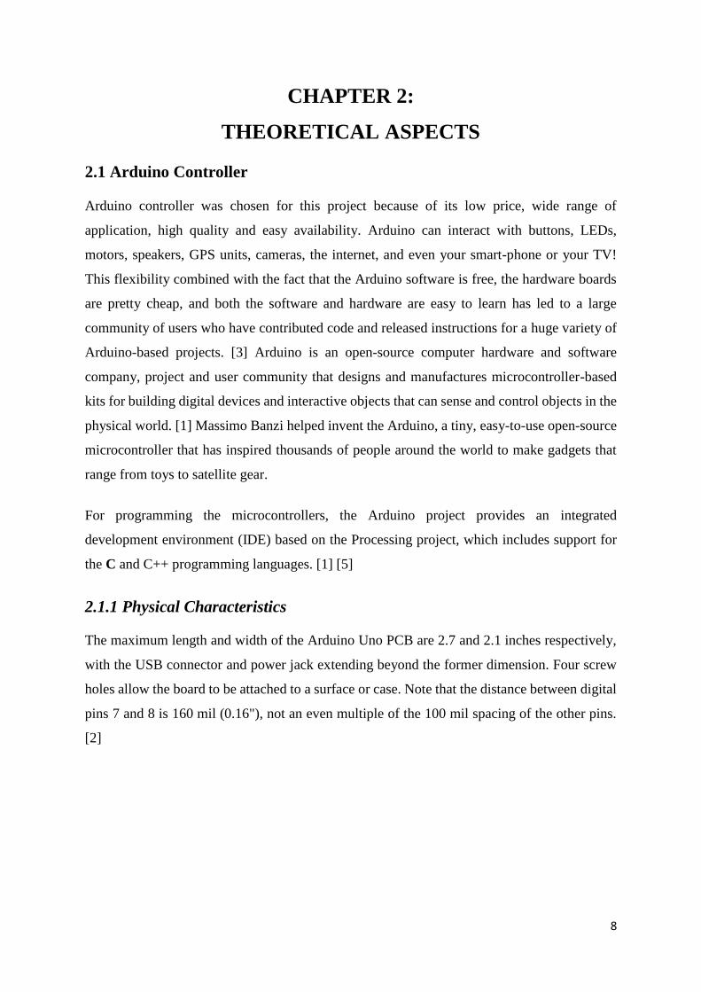
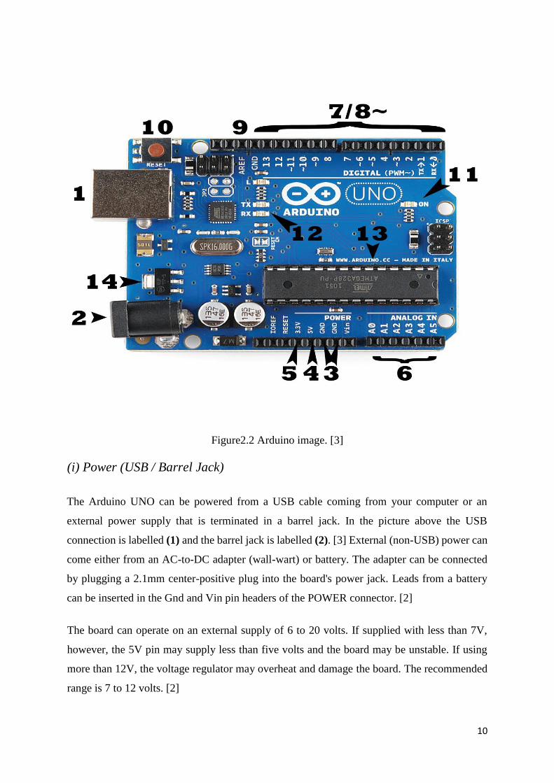
Figure2.1 Arduino image.[4]
The Arduino Uno is a microcontroller board based on the ATmega328 (datasheet). It has 14
digital input/output pins (of which 6 can be used as PWM outputs), 6 analogue inputs, a 16
MHz crystal oscillator, a USB connection, a power jack, an ICSP header, and a reset button. It
contains everything needed to support the microcontroller; simply connect it to a computer
with a USB cable or power it with an AC-to-DC adapter or battery to get started. The Uno
differs from all preceding boards in that it does not use the FTDI USB-to-serial driver chip.
Instead, it features the Atmega8U2 programmed as a USB-to-serial converter. [4]
There are many varieties/versions of Arduino boards and they can be used for different
purposes. Some boards look a bit different from the one below, but they have the majority of
these components in common:
10
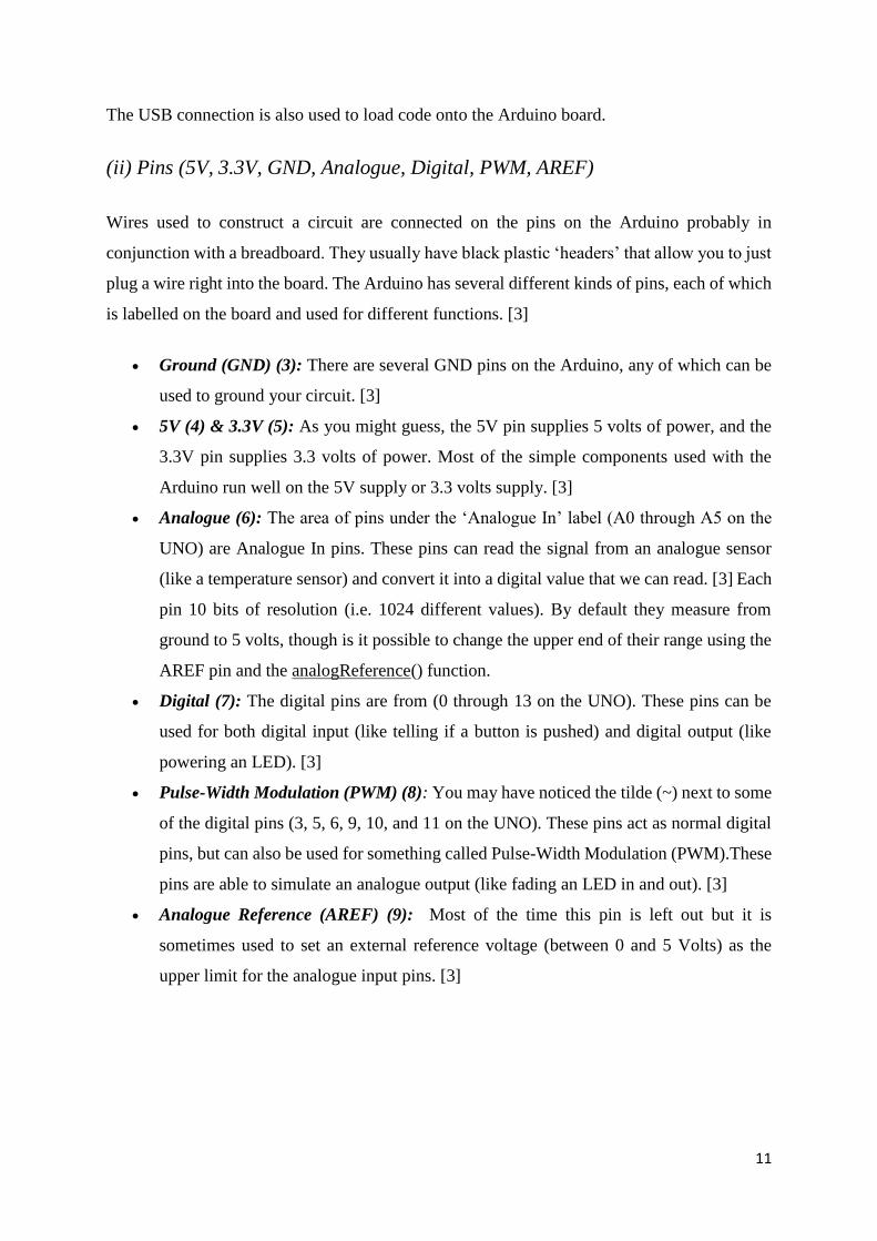
Figure2.2 Arduino image. [3]
(i) Power (USB / Barrel Jack)
The Arduino UNO can be powered from a USB cable coming from your computer or an
external power supply that is terminated in a barrel jack. In the picture above the USB
connection is labelled (1) and the barrel jack is labelled (2). [3] External (non-USB) power can
come either from an AC-to-DC adapter (wall-wart) or battery. The adapter can be connected
by plugging a 2.1mm center-positive plug into the board's power jack. Leads from a battery
can be inserted in the Gnd and Vin pin headers of the POWER connector. [2]
The board can operate on an external supply of 6 to 20 volts. If supplied with less than 7V,
however, the 5V pin may supply less than five volts and the board may be unstable. If using
more than 12V, the voltage regulator may overheat and damage the board. The recommended
range is 7 to 12 volts. [2]
11
The USB connection is also used to load code onto the Arduino board.
(ii) Pins (5V, 3.3V, GND, Analogue, Digital, PWM, AREF)
Wires used to construct a circuit are connected on the pins on the Arduino probably in
conjunction with a breadboard. They usually have black plastic ‘headers’ that allow you to just
plug a wire right into the board. The Arduino has several different kinds of pins, each of which
is labelled on the board and used for different functions. [3]
Ground (GND) (3): There are several GND pins on the Arduino, any of which can be
used to ground your circuit. [3]
5V (4) & 3.3V (5): As you might guess, the 5V pin supplies 5 volts of power, and the
3.3V pin supplies 3.3 volts of power. Most of the simple components used with the
Arduino run well on the 5V supply or 3.3 volts supply. [3]
Analogue (6): The area of pins under the ‘Analogue In’ label (A0 through A5 on the
UNO) are Analogue In pins. These pins can read the signal from an analogue sensor
(like a temperature sensor) and convert it into a digital value that we can read. [3] Each
pin 10 bits of resolution (i.e. 1024 different values). By default they measure from
ground to 5 volts, though is it possible to change the upper end of their range using the
AREF pin and the analogReference() function.
Digital (7): The digital pins are from (0 through 13 on the UNO). These pins can be
used for both digital input (like telling if a button is pushed) and digital output (like
powering an LED). [3]
Pulse-Width Modulation (PWM) (8): You may have noticed the tilde (~) next to some
of the digital pins (3, 5, 6, 9, 10, and 11 on the UNO). These pins act as normal digital
pins, but can also be used for something called Pulse-Width Modulation (PWM).These
pins are able to simulate an analogue output (like fading an LED in and out). [3]
Analogue Reference (AREF) (9): Most of the time this pin is left out but it is
sometimes used to set an external reference voltage (between 0 and 5 Volts) as the
upper limit for the analogue input pins. [3]
12
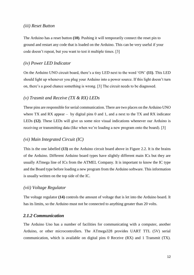
(iii) Reset Button
The Arduino has a reset button (10). Pushing it will temporarily connect the reset pin to
ground and restart any code that is loaded on the Arduino. This can be very useful if your
code doesn’t repeat, but you want to test it multiple times. [3]
(iv) Power LED Indicator
On the Arduino UNO circuit board, there’s a tiny LED next to the word ‘ON’ (11). This LED
should light up whenever you plug your Arduino into a power source. If this light doesn’t turn
on, there’s a good chance something is wrong. [3] The circuit needs to be diagnosed.
(v) Trasmit and Receive (TX & RX) LEDs
These pins are responsible for serial communication. There are two places on the Arduino UNO
where TX and RX appear – by digital pins 0 and 1, and a next to the TX and RX indicator
LEDs (12). These LEDs will give us some nice visual indications whenever our Arduino is
receiving or transmitting data (like when we’re loading a new program onto the board). [3]
(vi) Main Integrated Circuit (IC)
This is the one labelled (13) on the Arduino circuit board above in Figure 2.2. It is the brains
of the Arduino. Different Arduino board types have slightly different main ICs but they are
usually ATmega line of ICs from the ATMEL Company. It is important to know the IC type
and the Board type before loading a new program from the Arduino software. This information
is usually written on the top side of the IC.
(vii) Voltage Regulator
The voltage regulator (14) controls the amount of voltage that is let into the Arduino board. It
has its limits, so the Arduino must not be connected to anything greater than 20 volts.
2.1.2 Communication
The Arduino Uno has a number of facilities for communicating with a computer, another
Arduino, or other microcontrollers. The ATmega328 provides UART TTL (5V) serial
communication, which is available on digital pins 0 Receive (RX) and 1 Transmit (TX).
13
ATmega16U2 firmware on the board channels allows serial communication over USB is and
this appears as a virtual com port to software on the computer.
The '16U2 firmware uses the standard USB COM drivers, and no external driver is needed.
However, on Windows, an .info file is required. The Arduino software includes a serial monitor
which allows simple textual data to be sent to and from the Arduino board.
The RX and TX LEDs on the board will flash when data is being transmitted via the USB-to-
serial chip and USB connection to the computer (but not for serial communication on pins 0
and 1). [2]
2.1.3 Programming
The Arduino Uno can be programmed with the Arduino software (download). Select "Arduino
Uno from the Tools > Board menu (according to the microcontroller on your board). More
details, are found in the reference and tutorials. [2]
The ATmega328 on the Arduino Uno comes preburned with a bootloader that allows you to
upload new code to it without the use of an external hardware programmer. It communicates
using the original STK500 protocol (reference, C header files). [2]
You can also bypass the bootloader and program the microcontroller through the ICSP (In-
Circuit Serial Programming) header. The C or C++ language is used to program the Arduino.
2.1.4 Automatic (Software) Reset
Rather than requiring a physical press of the reset button before an upload, the Arduino Uno is
designed in a way that allows it to be reset by software running on a connected computer. One
of the hardware flow control lines (DTR) of the ATmega8U2/16U2 is connected to the reset
line of the ATmega328 via a 100 nanofarad capacitor. When this line is asserted (taken low),
the reset line drops long enough to reset the chip. [2] The Arduino software uses this capability
to allow you to upload code by simply pressing the upload button in the Arduino environment.
[2] This means that the bootloader can have a shorter timeout, as the lowering of DTR can be
well-coordinated with the start of the upload. This setup has other implications. When the Uno
is connected to either a computer running Mac OS X or Linux, it resets each time a connection
is made to it from software (via USB). For the following halfsecond or so, the bootloader is
running on the Uno. While it is programmed to ignore malformed data (i.e. anything besides
an upload of new code), it will intercept the first few bytes of data sent to the board after a
14
connection is opened. If a sketch running on the board receives one-time configuration or other
data when it first starts, make sure that the software with which it communicates waits a second
after opening the connection and before sending this data. [2]
The Uno contains a trace that can be cut to disable the auto-reset. The pads on either side of
the trace can be soldered together to re-enable it. It's labeled "RESET-EN". You may also be
able to disable the auto-reset by connecting a 110 ohm resistor from 5V to the reset line. [2]
2.1.5 USB Overcurrent Protection
The Arduino Uno has a resettable polyfuse that protects your computer's USB ports from shorts
and overcurrent. Although most computers provide their own internal protection, the fuse
provides an extra layer of protection. If more than 500 mA is applied to the USB port, the fuse
will automatically break the connection until the short or overload is removed. [2]
2.1.6 Technical specifications of Arduino
Microcontroller ATmega328
Operating Voltage 5V
Input Voltage (recommended) 7-12V
Input Voltage (limits) 6-20V
Digital I/O Pins 14 (of which 6 provide PWM output)
Analog Input Pins 6
DC Current per I/O Pin 40 mA
DC Current for 3.3V Pin 50 mA
Flash Memory 32 KB of which 0.5 KB used by bootloader
SRAM 2 KB
EEPROM 1 KB
Clock Speed 16MHz[3]
2.1.7 The Arduino was chosen for this project because of the following
reasons:
Inexpensive - Arduino boards are relatively inexpensive compared to other
microcontroller platforms. The least expensive version of the Arduino module can be
assembled by hand, and even the pre-assembled Arduino modules cost less than $50.[1]
15
Cross-platform - The Arduino Software (IDE) runs on Windows, Macintosh OSX, and
Linux operating systems. Most microcontroller systems are limited to Windows.[1]
Simple, clear programming environment - The Arduino Software (IDE) is easy-to-use
for beginners, yet flexible enough for advanced users to take advantage of as well.[1]
Open source and extensible software - The Arduino software is published as open
source tools, available for extension by experienced programmers. The language can
be expanded through C++ libraries, and people wanting to understand the technical
details can make the leap from Arduino to the AVR C programming language on which
it's based. Similarly, you can add AVR-C code directly into your Arduino programs if
you want to.[1]
Open source and extensible hardware - The plans of the Arduino boards are published
under a Creative Commons license, so experienced circuit designers can make their
own version of the module, extending it and improving it. Even relatively inexperienced
users can build the breadboard version of the module in order to understand how it
works and save money.[1]
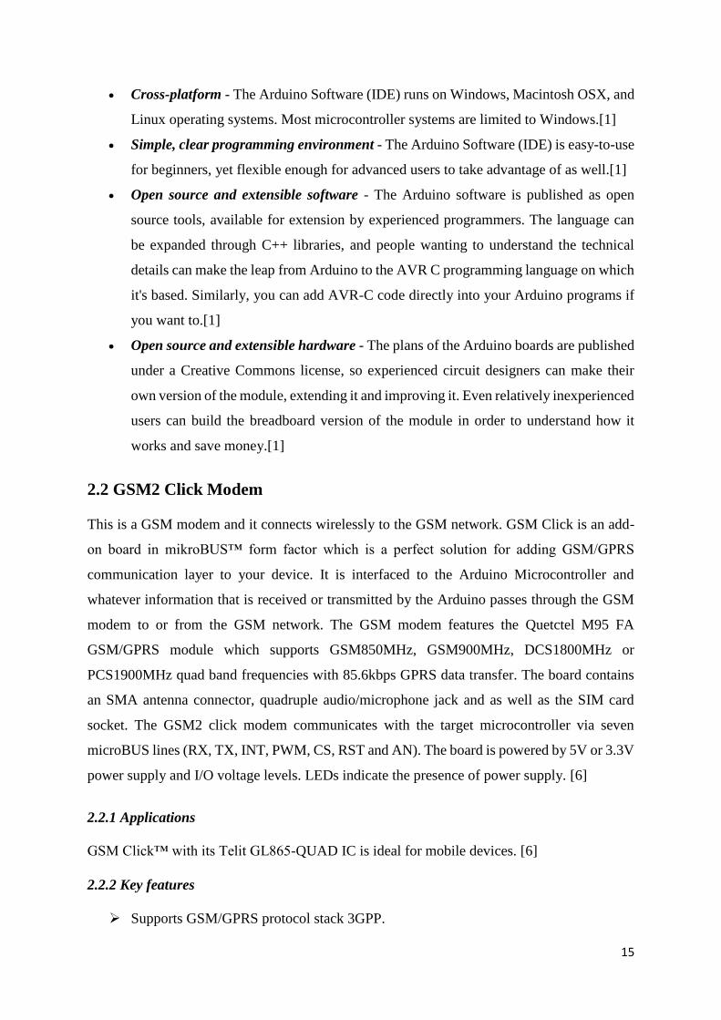
2.2 GSM2 Click Modem
This is a GSM modem and it connects wirelessly to the GSM network. GSM Click is an add-
on board in mikroBUS™ form factor which is a perfect solution for adding GSM/GPRS
communication layer to your device. It is interfaced to the Arduino Microcontroller and
whatever information that is received or transmitted by the Arduino passes through the GSM
modem to or from the GSM network. The GSM modem features the Quetctel M95 FA
GSM/GPRS module which supports GSM850MHz, GSM900MHz, DCS1800MHz or
PCS1900MHz quad band frequencies with 85.6kbps GPRS data transfer. The board contains
an SMA antenna connector, quadruple audio/microphone jack and as well as the SIM card
socket. The GSM2 click modem communicates with the target microcontroller via seven
microBUS lines (RX, TX, INT, PWM, CS, RST and AN). The board is powered by 5V or 3.3V
power supply and I/O voltage levels. LEDs indicate the presence of power supply. [6]
2.2.1 Applications
GSM Click™ with its Telit GL865-QUAD IC is ideal for mobile devices. [6]
2.2.2 Key features
Supports GSM/GPRS protocol stack 3GPP.
16
Supports GSM/GPRS 850/900/1800/ 1900 MHz Quad-band frequency.
On-board antenna connector as well as 3.5mm quadruple earphone/microphone jack.
SIM card socket integrated at the bottom side of the board.
2.2.3 Key Benefits
The GSM click 2 modem was chosen for this project because the GSM mode of
communication is a mature sytem which is now being used all over the world. The other
reasons for choosing the GSM click modem are listed below: [6]
mikroBUS™ form factor enables easy integration.
Supported in all mikroElektronika compilers.
Ready-to-use examples save development time.
Very compact design and affordable price.
Figure 2.3 GSM2 click modem. [6]
17
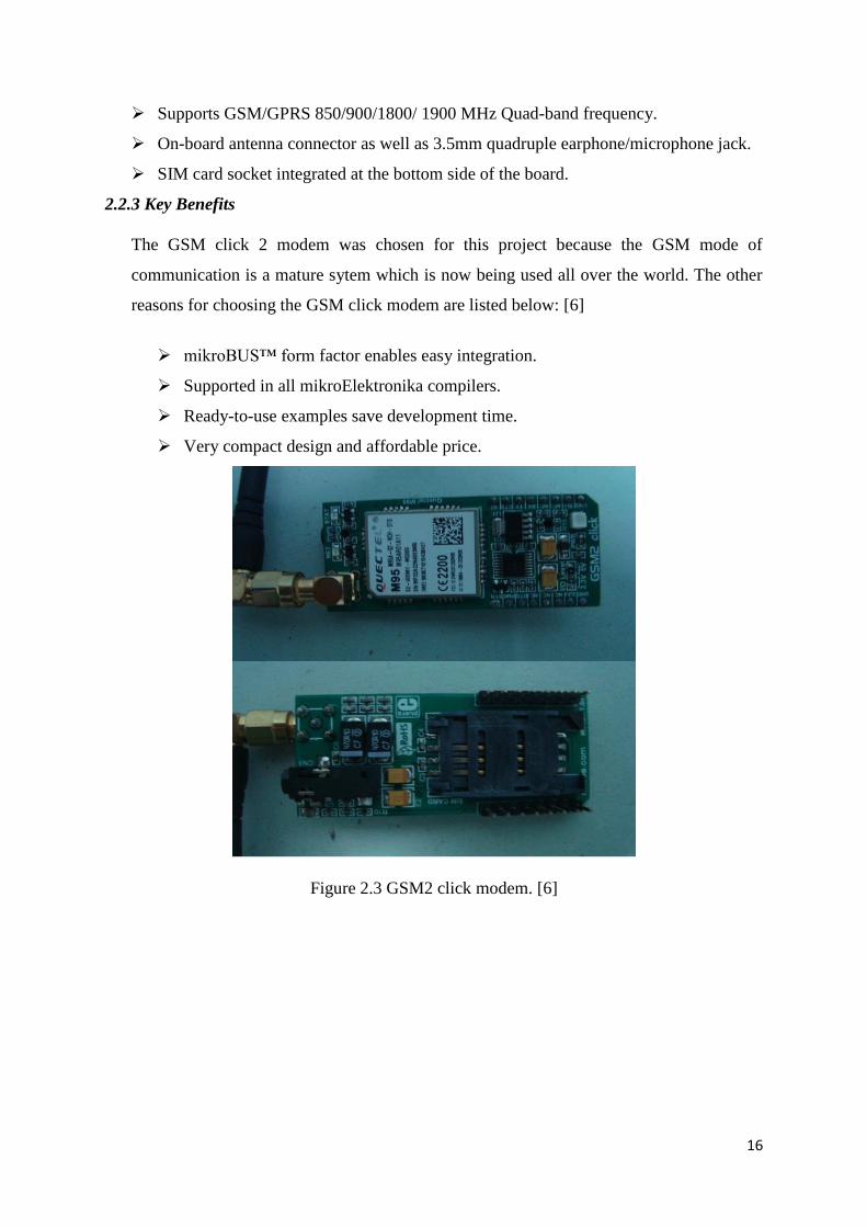
2.3 Liquid Crystal Display (LCD) (20*4)
It is an electronic display system. The liquid crystal display( LCD) has become the display
device of choice for microcontrollers. An LCD features low power, ful ASCII character
displays of one to four lines, from 16 to 40 characters per line and low cost. A 20*4 LCD is a
20 column and 4- row LCD. It means it can display 20 characters per line and 4 such lines are
available. The advantages of LCD’s are that, they are economical, easily programmable,
display a number of characters, compact, light and have low power consumption.
Figure 2.4 (20*4) LCD. [7]
18
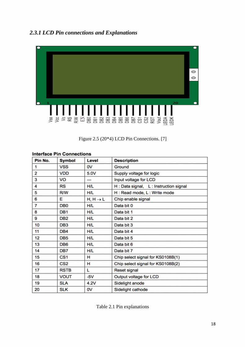
2.3.1 LCD Pin connections and Explanations
Figure 2.5 (20*4) LCD Pin Connections. [7]
Table 2.1 Pin explanations
19
8-Data pins carries 8-bit data or command from an external unit such as microcontroller.
Their are two registers in every LCD
(i) Command Register
(ii) Data Register
Command Register
When we send commands to LCD these commands go to Command register and are
processed there. When RS=0 Command Register is Selected.
Data Register
When we send Data to LCD it goes to data register and is processed there. When S=1Data
Register is selected.
EN (Enable Signal)
When you select the register(Command and Data) and set RW(read - write) now it is time to
execute the instruction. The instruction can be the 8-bit data or 8-bit command present on Data
lines of LCD. This requires an extra voltage push to execute the instruction and EN (enable)
signal is used for this purpose. Usually EN=0 and when we want to execute the instruction we
make it high EN=1 for some milli seconds. After this we again make it zero (low) EN=0. [8]
2.4 Polling Switches
Polling switches are used in the system to cast votes for the candidates. By pressing the switch
a vote is given to the desired candidate. The switches can be configured to work as normal
when open or closed depending on the design.
2.5 Power Supply
A power supply is an important part of any electronic circuit. It powers all the active and
passive components of an electronic system.
20
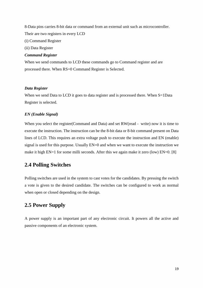
Figure 2.6 Power Supply Circuit Diagram
The transformer will step down AC input from 230V to about 12V AC and the full wave
rectifier will rectify the 12V AC to DC. The output DC voltage will then be smoothened first
by the 470uF 50V capacitor (C1). The smoothened output is also further smoothened by the
0.01uF Ceramic capacitor (C2), and any AC voltage in the output is short circuited (filtered
out) by this capacitor. Stabilisation of the output is done by the LM 7809 integrated circuit.
Further smoothening and filtering out of any AC in the output is done by the 0.01uF capacitor
(C3) and a stable 9V DC is outputted at the output terminals
2.6 Structure of the GSM network
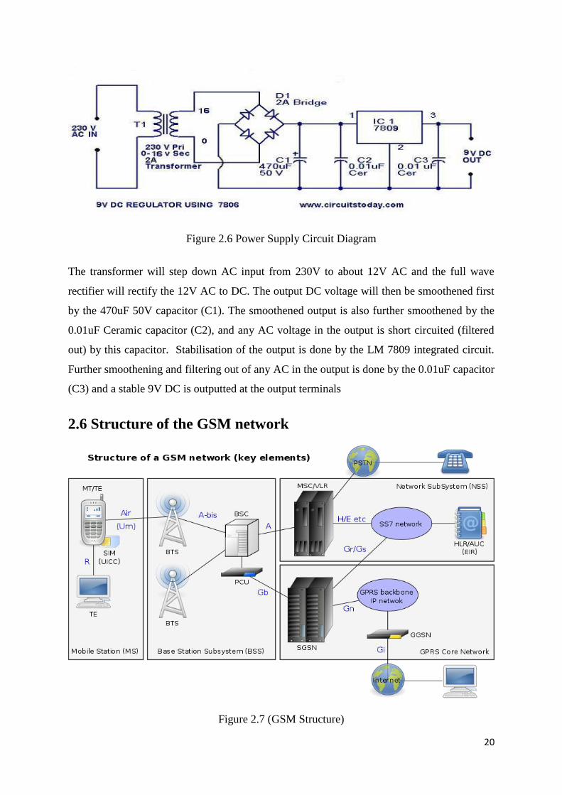
Figure 2.7 (GSM Structure)
21
The structure is composed of different sections that work together and these are:
(a) The mobile station (MS) and Mobile terminal (MT) – These are user interfaces.
(b) The Base Station Subsystem (BSS)-composed of the base stations and the base station
controllers (BSCs).
(c) The Network Switching Subsystem- composed of the Mobile switching centre (MSC)
and that is where registers such as VLR, HLR, AUC, EIR are found. Interconnection
with other GSM MSCs or PSTN, ISDN, PSPDN, CSPDN Networks is done here.
(d) GPRS core network- This is where packet based internet connections are done
(e) The Operations and support System (OSS) - meant for monitoring and maintenance of
the network.
2.7 Short message Service (SMS)
This is a service that is of particular interest to this project because messages are going to be
sent from the GSM module connected to the Arduino to a programmed Telephone number at
the Monitoring Station via the GSM mobile network.
This is a service used for sending or receiving sms’ at very low costs from user user. All the
mobile operators in Zimbabwe provide the sms service. A limit of 160 alphanumeric characters
are allowed to be sent at any instance via the Short Message Service centre (SMSC). SMS
service can be from one user to another user, One user to many users ( Broadcasting) or many
users to one user ( updating). The SMSC receives a message and then directs it to the
appropriate device. The SMSC does this by sending an SMS request to the Home Location
Register (HLR) in order to find the customer and once the HLR receives the request it the
responds to the SMSC with the Subscriber’s status for example inactive, active or where the
customer is roaming. The SMSC then purges the device and if it responds the message gets
delivered. Verification is then sent to the SMSC that the end user has received the message
then this message will be categorised as sent so that an attempt to send it again will not be
made.
22
2.8 Monitoring Centre
This is where all the voting results are going to be sent by the GSM module via the GSM
network using Short Message Service. Results of the voting or election process are going to be
announced from the monitoring centre.
23
REFERENCES
[1] https://www.arduino.cc/en/guide/introduction (accessed October 7 2016)
[2] http://www.farnel.com/datasheets/1682209.pdf (accessed October 7 2016)
[3] https://learn.sparkfun.com/tutorials/what-is-an-arduino
[4] http://www.digital.csic.es/bitstream/120261/127788/7/D-C-Arduino uno.pdf (accessed
October 7 2016)
[5] https://www.arduino.cc/en/main/software (accessed October 7 2016)
[6] http://www.mikroe.com/click/gsm2 (accessed October 7 2016)
[7] G. J. Lipovski, “Single and Multi-Chip Microcontroller Interfacing,” University of Texas,
Academic Press 1999
[8] www.microcontroller-project.com/16*2 LCD (Accessed October 9 2016)
[9] www.wisegeek.org/what-is-an-infrared-sensor.html
24
CHAPTER 3
RESEARCH METHODS AND TECHNIQUES
3.1 Introduction
This chapter describes in detail the tools used for example software used, the architectural
design of the project, the development steps, techniques and method used to integrate all the
parts (subsystems) in this project. The Waterfall project development method was used for this
project. It is a stage by stage system and the advantage of this system is that it is possible to
return to the previous stage or stages whenever a hiccup or error arises. Trouble shooting is
easy when using this method.
3.1.1 Step 1- Literature survey
Surveys for all the information needed for this project were done at this stage. This included
outlining the objectives of this project and then discussing with the project supervisors and
constant consultation was done as the project was progressing in order to keep the project in
line with the objectives and aim. The other sources of literature were books, the internet and
discussions with fellow students.
3.1.2 Step 2- Conceptual design
With all the needed information now at hand flow charts and block diagrams were designed.
Components were sourced and the project was divided into small tasks in order to reduce the
complexity. Some of the components were found at the University’s Department of Physics
and Telecommunications Laboratory and some were sourced outside. Availability of
programming software was also confirmed.
3.1.3 Step 3- Building stage
This is the stage were all the components were put together to build one complete system thus
making it the critical stage of the project. Components like the Power supply, Arduino Uno,
GSM module, polling switches, LCD, Buzzer and programming software were put together at
this stage.
25
3.1.4 Step 4- Testing
Any system that is designed needs to be tested in order to verify if the design is performing
according to the required standards. At this stage the whole system was powered, software was
loaded and test runs were carried out. Software bugs, mechanical faults, electrical faults and
electronic faults were all cleared.
3.1.5 Step 5- Results
All the results are documented and a proper analysis of them is made to check if the objectives
were met and if so then the project was a success. If the results do not tally with the expected
results then troubleshooting has to be done. Scalability of a system will always depend on the
present success of a system so even if results show that the objectives were met there will be
still room for improvement of the system in order to meet new and bigger demands.
3.1.6 Step 6- Documentation
Documentation is a very important component of any project because documents are used as
future reference. Documents are used for fault finding, improvement of the system, knowledge
transfer and budget formulation. A system with proper documentation will surely pass the test
of time
3.1.7 Methodology
The Waterfall Model was used for this project. It is also referred to as a linear-sequential life
cycle model. It is very simple to understand and use. In a waterfall model, each phase must
be completed fully before the next phase can begin. This model was used because the project
is small. At the end of each phase, a review took place to determine if the project was on the
right path and whether or not to continue or discard the project. In waterfall model phases do
not overlap. [1]
Advantages of waterfall model:
This model is simple, easy to understand and use.
It is easy to manage due to the rigidity of the model – each phase has specific
deliverables and a review process.
In this model phases are processed and completed one at a time. Phases do not overlap.
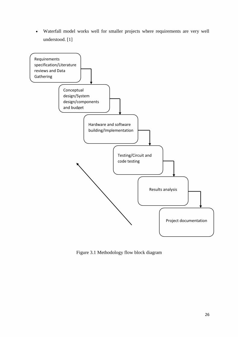
26
Waterfall model works well for smaller projects where requirements are very well
understood. [1]
Figure 3.1 Methodology flow block diagram
Requirements
specification/Literature
reviews and Data
Gathering
Conceptual
design/System
design/components
and budget
Hardware and software
building/Implementation
Testing/Circuit and
code testing
Results analysis
Project documentation
27
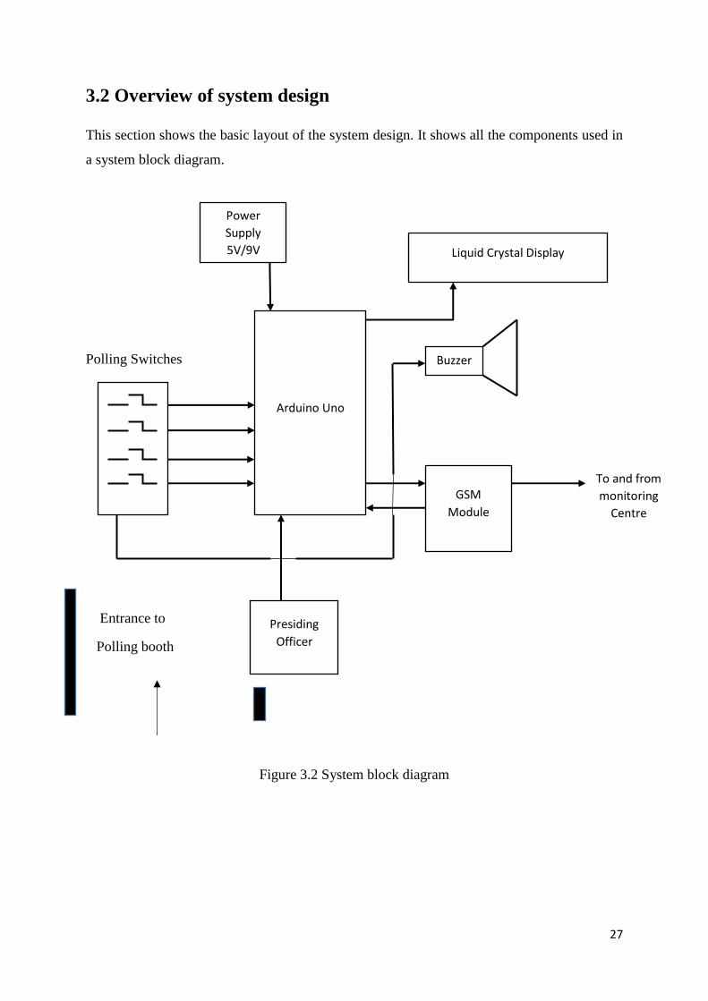
3.2 Overview of system design
This section shows the basic layout of the system design. It shows all the components used in
a system block diagram.
Polling Switches
Entrance to
Polling booth
Figure 3.2 System block diagram
Power
Supply
5V/9V
Arduino Uno
Liquid Crystal Display
GSM
Module
Buzzer
To and from
monitoring
Centre
Presiding
Officer
28
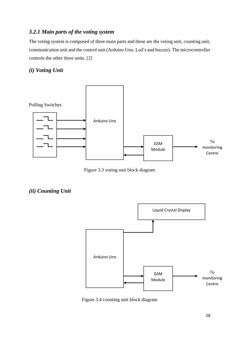
3.2.1 Main parts of the voting system
The voting system is composed of three main parts and these are the voting unit, counting unit,
communication unit and the control unit (Arduino Uno, Led’s and buzzer). The microcontroller
controls the other three units. [2]
(i) Voting Unit
Polling Switches
Figure 3.3 voting unit block diagram
(ii) Counting Unit
Figure 3.4 counting unit block diagram
Arduino Uno
GSM
Module
To
monitoring
Centre
Arduino Uno
Liquid Crystal Display
GSM
Module
To
monitoring
Centre
29
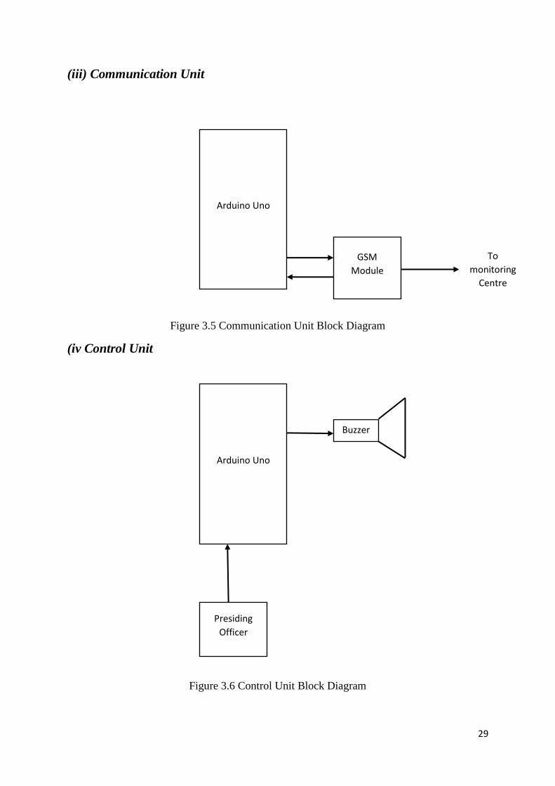
(iii) Communication Unit
Figure 3.5 Communication Unit Block Diagram
(iv Control Unit
Figure 3.6 Control Unit Block Diagram
Arduino Uno
GSM
Module
To
monitoring
Centre
Arduino Uno
Presiding
Officer
Buzzer
30
3.3 Interfacing Hardware
Interfacing is very important in any electronic project and this section of the project is going to
look at hardware interfacing. An interface is a shared boundary across which two separate
hardware components exchange information. The exchange can be between peripheral devices,
humans and combinations of these. A hardware interface is described by the mechanical,
electrical and logical signals at the interface and the protocol for sequencing them (sometimes
called signalling). Hardware interfaces can be parallel with several electrical connections
carrying parts of the data simultaneously, or serial where data is sent one bit at a time. Interface
analysis verifies that the requirements for the complex electronics interfaces with other
hardware, software, users, and other systems are correct, consistent, complete, accurate, and
testable. [3]
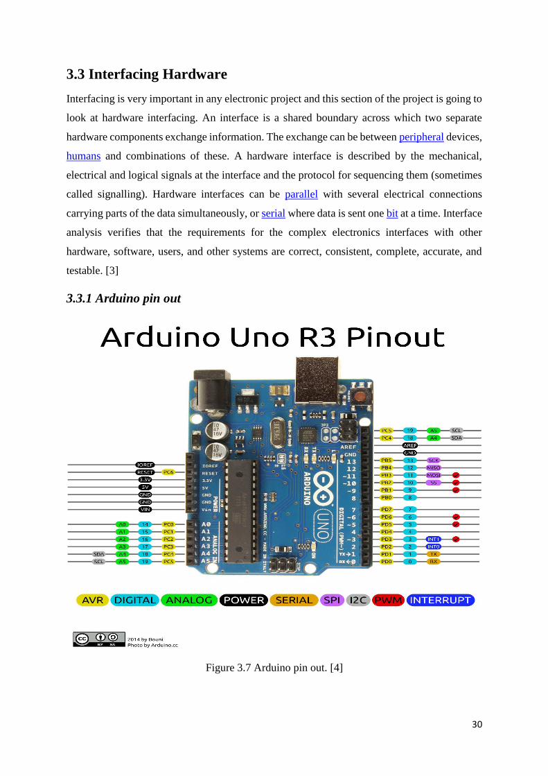
3.3.1 Arduino pin out
Figure 3.7 Arduino pin out. [4]
31
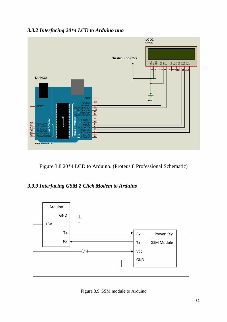
3.3.2 Interfacing 20*4 LCD to Arduino uno
Figure 3.8 20*4 LCD to Arduino. (Proteus 8 Professional Schematic)
3.3.3 Interfacing GSM 2 Click Modem to Arduino
Figure 3.9 GSM module to Arduino
DIG
ITA
L (~
PW
M)
AN
AL
OG
IN
AT
ME
GA
328P
-PU
1121
~~
~
~~
~
mic
roco
ntro
lan
do
s.b
log
sp
ot.c
om
TX
RX PD0/RXD0
PD1/TXD1
PD2/INT02
PD3/INT13
PD4/T0/XCK4
PD5/T15
PD6/AIN06
PD7/AIN17
PB0/ICP1/CLKO8
PB1/OC1A9
PB2/SS/OC1B10
PB3/MOSI/OC2A11
PB4/MISO12
PB5/SCK13
AREF
PC5/ADC5/SCLA5
PC4/ADC4/SDAA4
PC3/ADC3A3
PC2/ADC2A2
PC1/ADC1A1
PC0/ADC0A0
RESET
DUINO1
ARDUINO UNO R3
D7
14
D6
13
D5
12
D4
11D
310
D2
9D
18
D0
7
E6
RW
5R
S4
VS
S1
VD
D2
VE
E3
LCD1LM016L
GND
To Arduino (5V)
DIG
ITA
L (~
PW
M)
AN
AL
OG
IN
AT
ME
GA
328P
-PU
1121
~~
~
~~
~
mic
roco
ntro
lan
do
s.b
log
sp
ot.c
om
TX
RX PD0/RXD0
PD1/TXD1
PD2/INT02
PD3/INT13
PD4/T0/XCK4
PD5/T15
PD6/AIN06
PD7/AIN17
PB0/ICP1/CLKO8
PB1/OC1A9
PB2/SS/OC1B10
PB3/MOSI/OC2A11
PB4/MISO12
PB5/SCK13
AREF
PC5/ADC5/SCLA5
PC4/ADC4/SDAA4
PC3/ADC3A3
PC2/ADC2A2
PC1/ADC1A1
PC0/ADC0A0
RESET
DUINO2
ARDUINO UNO R3
D7
14
D6
13
D5
12
D4
11D
310
D2
9D
18
D0
7
E6
RW
5R
S4
VS
S1
VD
D2
VE
E3
LCD2LM016L
GND
To Arduino (5V)
Arduino
GND
+5V
Tx
Rx
Rx Power Key
Tx GSM Module
Vcc
GND
32
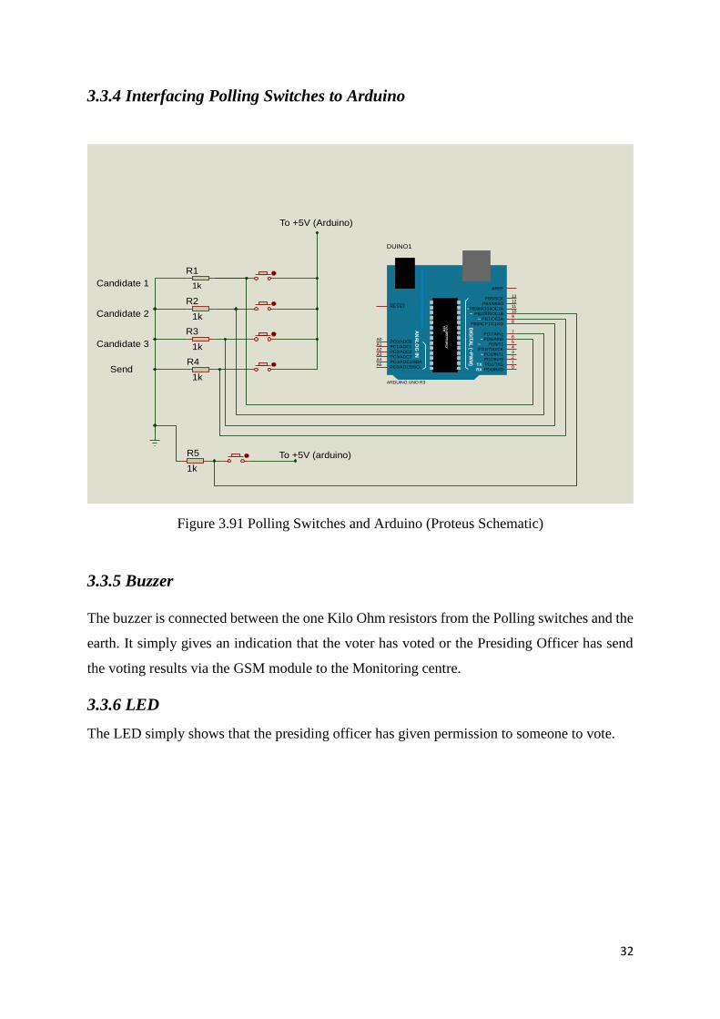
3.3.4 Interfacing Polling Switches to Arduino
Figure 3.91 Polling Switches and Arduino (Proteus Schematic)
3.3.5 Buzzer
The buzzer is connected between the one Kilo Ohm resistors from the Polling switches and the
earth. It simply gives an indication that the voter has voted or the Presiding Officer has send
the voting results via the GSM module to the Monitoring centre.
3.3.6 LED
The LED simply shows that the presiding officer has given permission to someone to vote.
Candidate 1
Candidate 2
Candidate 3
Send
To +5V (Arduino)
To +5V (arduino)
R1
1k
R2
1k
R3
1k
R4
1k
DIG
ITA
L (~
PW
M)
AN
AL
OG
IN
AT
ME
GA
328P
-PU
1121
~~
~
~~
~
mic
roco
ntro
lan
do
s.b
log
sp
ot.c
om
TX
RX PD0/RXD0
PD1/TXD1
PD2/INT02
PD3/INT13
PD4/T0/XCK4
PD5/T15
PD6/AIN06
PD7/AIN17
PB0/ICP1/CLKO8
PB1/OC1A9
PB2/SS/OC1B10
PB3/MOSI/OC2A11
PB4/MISO12
PB5/SCK13
AREF
PC5/ADC5/SCLA5
PC4/ADC4/SDAA4
PC3/ADC3A3
PC2/ADC2A2
PC1/ADC1A1
PC0/ADC0A0
RESET
DUINO1
ARDUINO UNO R3
R5
1k
33
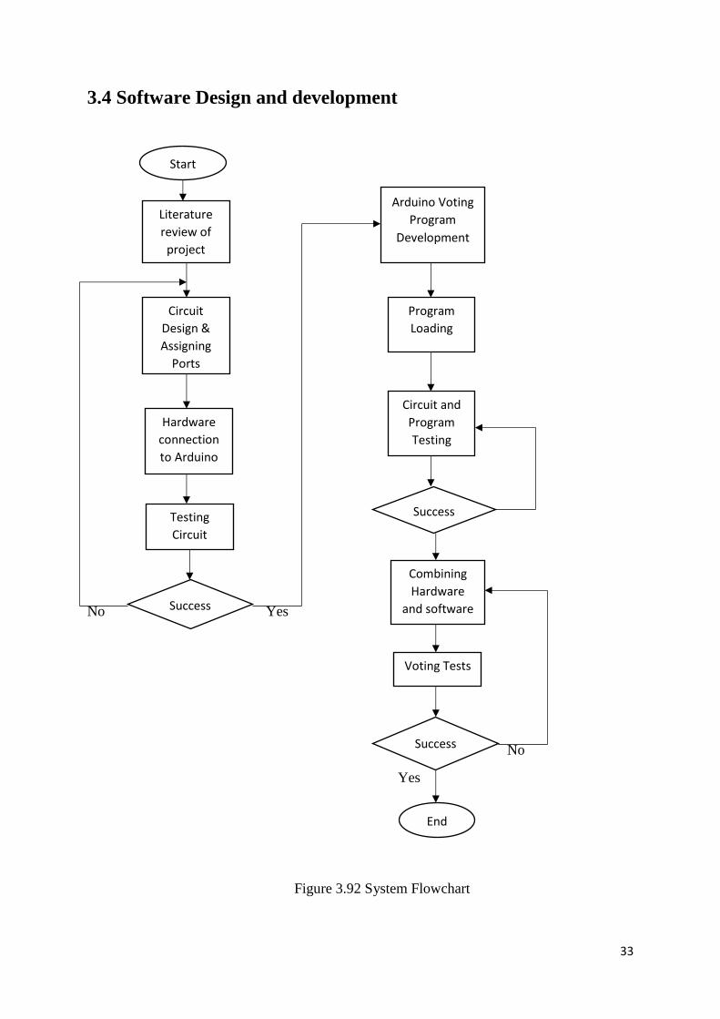
3.4 Software Design and development
No Yes
No
Yes
Figure 3.92 System Flowchart
Start
Literature
review of
project
Circuit
Design &
Assigning
Ports
Hardware
connection
to Arduino
Testing
Circuit
Success
Arduino Voting
Program
Development
Program
Loading
Circuit and
Program
Testing
Success
Combining
Hardware
and software
Voting Tests
Success
End
34
The software program was written in C language using the Arduino Integrated Development
Environment Language. Proteus 8 Professional was used to draw most of the Circuit diagrams.
3.5 Performance Evaluation and testing
After building the whole hardware system, the software program was uploaded onto the system.
The whole system was tested and results started showing and this was a great motivation. The
system was showing votes for each candidate and the total votes which were then sent to the
monitoring center.
35
REFERENCES
[1] istqbexamcertification.com/what-is waterfall-model ( accessed October 14 2016)
[2] P.Diponker, R.KSobuj “ apreview on Microcontroller Based Electronic Voting Machine,”
International Journal of Information and Electronics Engineering, Volume 3. Number 2, March
2013
[3] www.hq.nasa.gov/complex electronics/interface-analysis.htm
[4] https://github.com/Bouni/Arduino-Pinout
[5] www.hobbytronics.co.uk ( accessed October 21 2016)
[6] www.vishay.com/docs/37306/lcd016n004b.pdf (accessed October 23 2016)
[7] https:www.arduino.cc/en/uploads/tutorial/lcd-bsae-bb-fritz.png
36
CHAPTER 4
RESULTS AND ANALYSIS
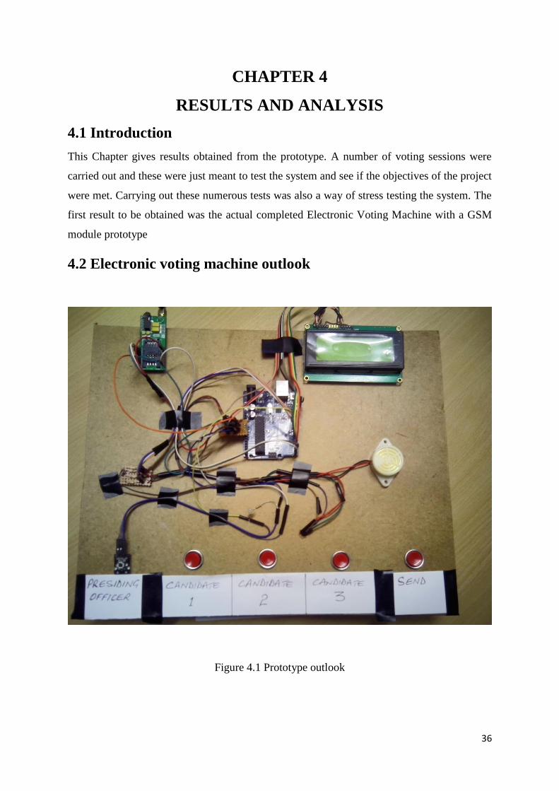
4.1 Introduction
This Chapter gives results obtained from the prototype. A number of voting sessions were
carried out and these were just meant to test the system and see if the objectives of the project
were met. Carrying out these numerous tests was also a way of stress testing the system. The
first result to be obtained was the actual completed Electronic Voting Machine with a GSM
module prototype
4.2 Electronic voting machine outlook
Figure 4.1 Prototype outlook
37
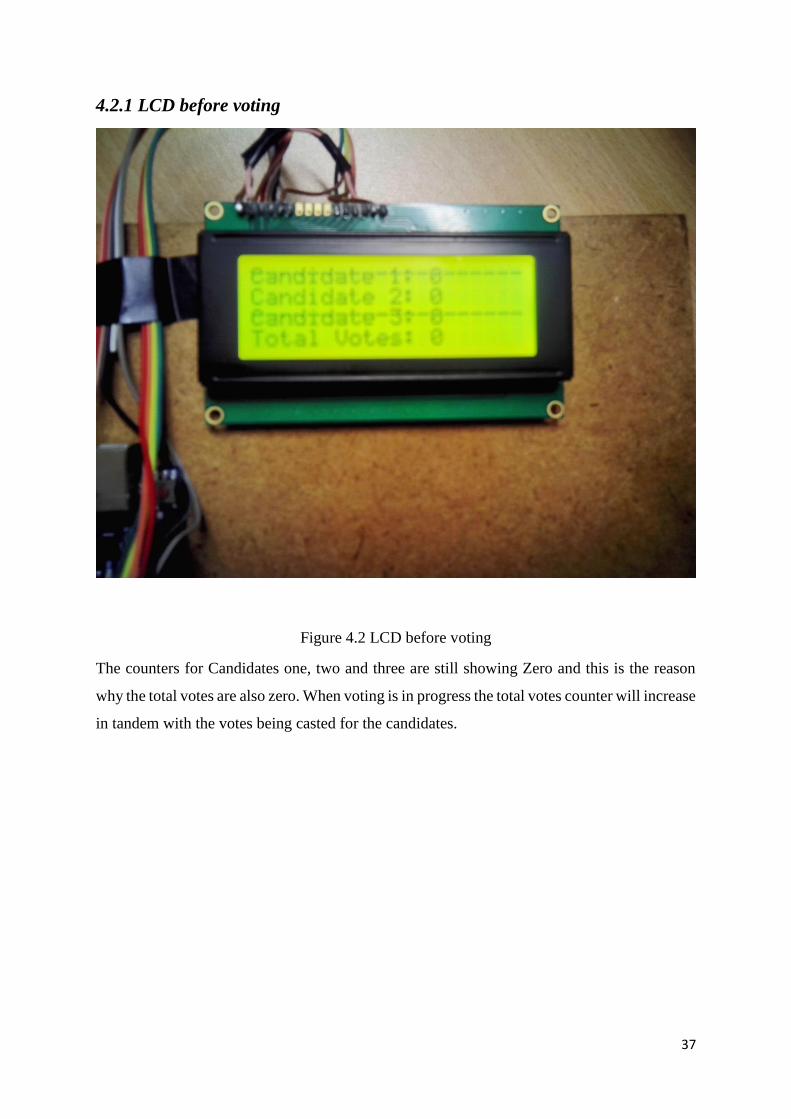
4.2.1 LCD before voting
Figure 4.2 LCD before voting
The counters for Candidates one, two and three are still showing Zero and this is the reason
why the total votes are also zero. When voting is in progress the total votes counter will increase
in tandem with the votes being casted for the candidates.
38
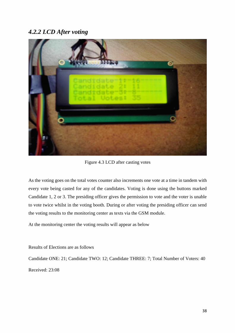
4.2.2 LCD After voting
Figure 4.3 LCD after casting votes
As the voting goes on the total votes counter also increments one vote at a time in tandem with
every vote being casted for any of the candidates. Voting is done using the buttons marked
Candidate 1, 2 or 3. The presiding officer gives the permission to vote and the voter is unable
to vote twice whilst in the voting booth. During or after voting the presiding officer can send
the voting results to the monitoring center as texts via the GSM module.
At the monitoring center the voting results will appear as below
Results of Elections are as follows
Candidate ONE: 21; Candidate TWO: 12; Candidate THREE: 7; Total Number of Voters: 40
Received: 23:08
39
There will be a date and time stamp on the message. The mobile number that will have sent the
message is also shown, this means polling stations can be identified by their Telephone
numbers.
The frequency of sending the results can be a negotiated and agreed upon position amongst the
interested stakeholders. It can also be in accordance to the laws of the country, organization,
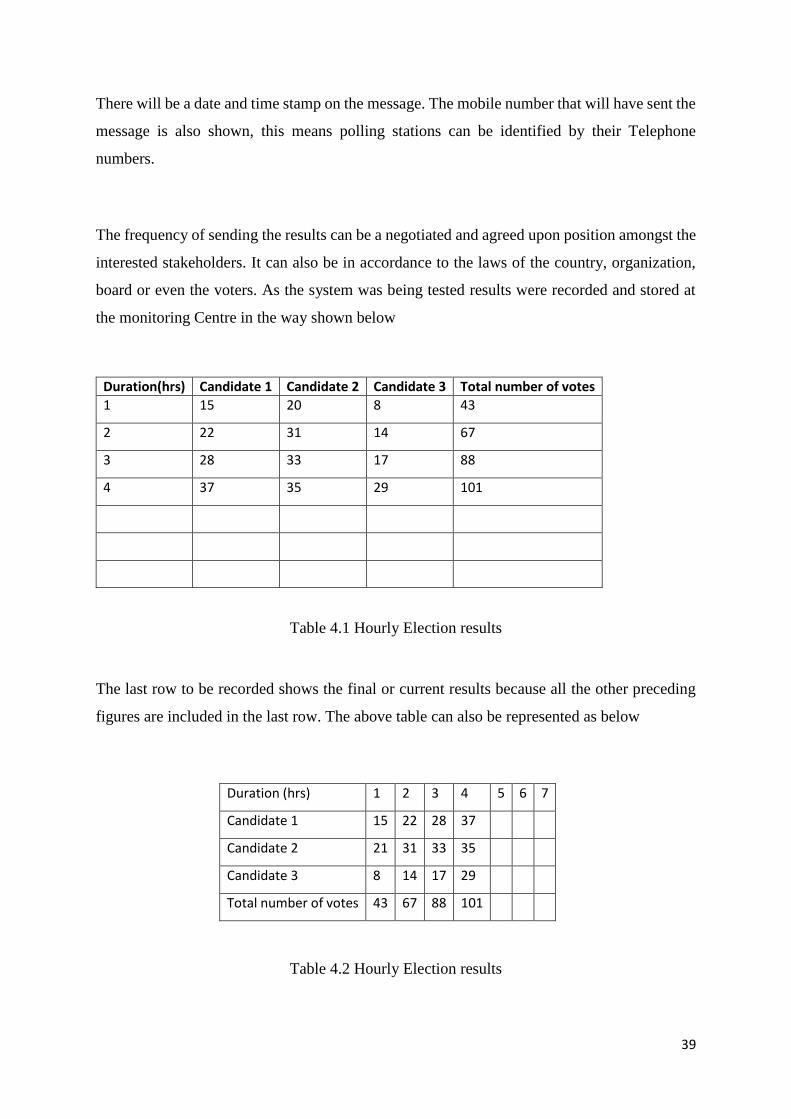
board or even the voters. As the system was being tested results were recorded and stored at
the monitoring Centre in the way shown below
Duration(hrs) Candidate 1 Candidate 2 Candidate 3 Total number of votes
1 15 20 8 43
2 22 31 14 67
3 28 33 17 88
4 37 35 29 101
Table 4.1 Hourly Election results
The last row to be recorded shows the final or current results because all the other preceding
figures are included in the last row. The above table can also be represented as below
Duration (hrs) 1 2 3 4 5 6 7
Candidate 1 15 22 28 37
Candidate 2 21 31 33 35
Candidate 3 8 14 17 29
Total number of votes 43 67 88 101
Table 4.2 Hourly Election results
40
From the above results in tables 4.1 and 4.2 pie charts, bar graphs and ordinary graphs can be
drawn for further analysis. These results can also be analyzed by Region or locality for future
use.
41
REFERENCES
[1] https://www.reference .com/math/tabular-data-presentation (Accessed October 30 2016)
42
CHAPTER 5
CONCLUSIONS
5.1 Introduction
The main objective of this project was to construct a very simple low cost Electronic Voting
System with a GSM module and this objective was achieved. This chapter looks at the
conclusion and recommendations for this prototype project.
5.2 Recommendations
Electronic Voting System with a GSM module is the way to go because of the following
reasons
(a) It is very simple and of low cost, thus it serves resources
(b) The GSM Technology is a widely used and mature Technology
(c) If properly implemented it leaves very little room for errors
(d) Precious time is also saved by using this EVM
(e) The EVM is scalable, thus it can meet future demands or workloads
(f) Modern Technologies are taking over in many spheres of life thus the EVM is a
sure way of tracking technology.
5.3 Conclusion
The aims and objectives of the project were met in the developed prototype. The Saving of
resources is now of paramount importance in any given economic setup and the Electronic
Voting Machine is one sure way of saving resources be it in sports, education, social, politics
and business. The EVM also builds voter confidence.
43
APPENDIX A
SOFTWARE CODE FOR THE SYSTEM
// include the library code:
#include <LiquidCrystal.h>
#define SENDTONUMBER "+263774222134"
long int candidate1 = 0;
long int candidate2 = 0;
long int candidate3 = 0;
long int totalVotes = 0;
const int vote1Pin = 6; // the number of the pushbutton pin
const int vote2Pin = 7; // the number of the pushbutton pin
const int vote3Pin = 8; // the number of the pushbutton pin
const int countAndSMSPin = 9; // the number of the pushbutton pin
const int SensorPin = 10; // sensor
int vote1PinState = 0;
int vote2PinState = 0;
int vote3PinState = 0;
int countAndSMSState = 0;
int SensorPinState = 0;
44
String mssg = "";
unsigned long debounceTime = 300;
const int ledPin = 13; // the number of the LED pin to show if vote has been added to
candidate
bool voteEnableFlag = false;
// initialize the library with the numbers of the interface pins
LiquidCrystal lcd(12, 11, 5, 4, 3, 2);
void setup() {
Serial.begin(9600);
// set up the LCD's number of columns and rows:
lcd.begin(20, 4);
// put your setup code here, to run once:
pinMode(ledPin, OUTPUT);
// initialize the pushbutton pin as an input:
pinMode(vote1Pin, INPUT);
pinMode(vote2Pin, INPUT);
pinMode(vote3Pin, INPUT);
pinMode(countAndSMSPin, INPUT);
45
pinMode(SensorPin, INPUT);
}
void loop() {
// put your main code here, to run repeatedly:
vote1PinState = digitalRead(vote1Pin);
vote2PinState = digitalRead(vote2Pin);
vote3PinState = digitalRead(vote3Pin);
countAndSMSState = digitalRead(countAndSMSPin);
SensorPinState = digitalRead(SensorPin);
totalVotes = candidate1 + candidate2 + candidate3;
dispOnLCD();
if(SensorPinState == LOW){
delay(debounceTime);
voteEnableFlag = true;
Serial.print("Vote Enable Flag = ");
Serial.println(voteEnableFlag);
}
if(voteEnableFlag == true){
if (vote1PinState == HIGH) {
digitalWrite(ledPin, HIGH);// turn LED on:
46
delay(debounceTime);
candidate1++;
delay(250);
voteEnableFlag = false;
digitalWrite(ledPin, LOW);
}
if (vote2PinState == HIGH) {
digitalWrite(ledPin, HIGH);// turn LED on:
delay(debounceTime);
candidate2++;
delay(250);
voteEnableFlag = false;
digitalWrite(ledPin, LOW);
}
if (vote3PinState == HIGH) {
digitalWrite(ledPin, HIGH);// turn LED on:
delay(debounceTime);
candidate3++;
47
delay(250);
voteEnableFlag = false;
digitalWrite(ledPin, LOW);
}
}
if (countAndSMSState == HIGH) {
digitalWrite(ledPin, HIGH);// turn LED on:
delay(debounceTime);
mssg = "Results of Elections are as follows\n";
mssg += "Candidate ONE: ";
mssg += String(candidate1);
mssg += "; Candidate TWO: ";
mssg += String(candidate2);
mssg += "; Candidate THREE: ";
mssg += String(candidate3);
mssg += "; Total Number Of Voters: ";
mssg += String(totalVotes);
sendSMS(mssg, SENDTONUMBER);
48
delay(100);
digitalWrite(ledPin, LOW);
}
}
void sendSMS(String message, char mobile_number[14]) //function to send sms, takes
message and phone number as arguments
{
delay(1200);
Serial.print("AT");
delay(1200);
bool bOK = false;
while (Serial.available() > 0)
{
char inChar = (char)Serial.read();
bOK = true;
}
if(bOK)
{
int index = 0;
Serial.println();
49
Serial.println("AT+CMGF=1"); // sets the SMS mode to text
delay(100);
delay(1200);
bool bOK = false;
while (Serial.available() > 0) {
//Serial.write(Serial.read());
char inChar = (char)Serial.read();
bOK = true;
}
if(bOK)
{
Serial.println();
Serial.print("AT+CMGS=\""); // send the SMS number
Serial.print(mobile_number);
Serial.println("\"");
delay(1000);
Serial.print(message); // SMS body
delay(500);
Serial.write(0x1A);
Serial.write(0x0D);
Serial.write(0x0A);
50
}
}
}
void dispOnLCD(){
// Print a message to the LCD.
lcd.setCursor(0, 0);
lcd.print("Candidate 1: ");
lcd.setCursor(13, 0);
lcd.print(candidate1);
lcd.setCursor(0, 1);
lcd.print("Candidate 2: ");
lcd.setCursor(13, 1);
lcd.print(candidate2);
lcd.setCursor(0, 2);
lcd.print("Candidate 3: ");
lcd.setCursor(13, 2);
lcd.print(candidate3);
51
lcd.setCursor(0, 3);
lcd.print("Total Votes: ");
lcd.setCursor(13, 3);
lcd.print(totalVotes);
}
void clrLCD(){
delay(2000);
lcd.begin(20, 4);
// Print a message to the LCD.
lcd.print(" ");
lcd.setCursor(0,1);
lcd.print(" ");
lcd.setCursor(0,2);
lcd.print(" ");
lcd.setCursor(0,3);
lcd.print(" ");
}
Related Documents


![Gsm Based Electronic Voting Machine [Autosaved]](https://static.cupdf.com/doc/110x72/577c804b1a28abe054a81316/gsm-based-electronic-voting-machine-autosaved.jpg)